1
Intel® Server Board S5000PAL / S5000XAL TPS
Connector / Header Locations and Pin-outs
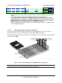
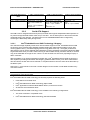
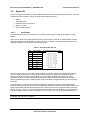
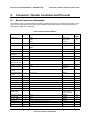
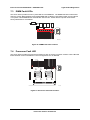
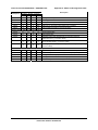
Connector
Quantity
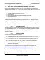
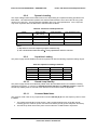
System Recovery
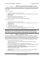
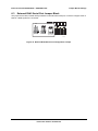
Setting Jumpers
5.2
Reference Designators
4
Connector Type
J1D1, J1D2, J1D3, J3H1
Jumper
Pin
Count
3
Power Connectors
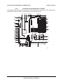
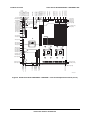
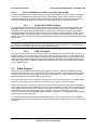
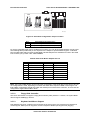
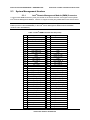
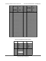
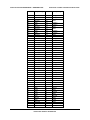
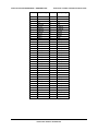
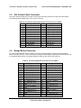
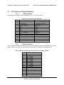
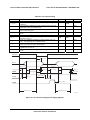
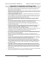
The main power supply connection is obtained using an SSI compliant 2x12 pin connector (J3K3). In
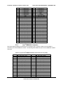
addition, there are two additional power related connectors; one SSI compliant 2x4 pin power connector
(J3K4) providing support for additional 12V, and one SSI compliant 1x5 pin connector (J1K1) providing
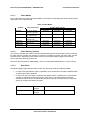
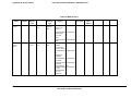
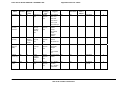
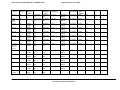
I2C monitoring of the power supply. The following tables define the connector pin-outs.
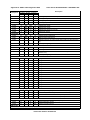
Table 10. Power Connector Pin-out (J3K3)
1
Pin
Signal
+3.3Vdc
Color
Orange
Pin
13
Signal
+3.3Vdc
Color
Orange
2
+3.3Vdc
Orange
14
-12Vdc
Blue
3
GND
Black
15
GND
Black
4
+5Vdc
Red
16
PS_ON#
Green
5
GND
Black
17
GND
Black
6
+5Vdc
Red
18
GND
Black
7
GND
Black
19
GND
Black
8
PWR_OK
Gray
20
RSVD_(-5V)
White
9
5VSB
Purple
21
+5Vdc
Red
10
+12Vdc
Yellow
22
+5Vdc
Red
11
+12Vdc
Yellow
23
+5Vdc
Red
12
+3.3Vdc
Orange
24
GND
Black
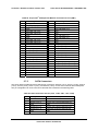
Table 11. 12V Power Connector Pin-out (J3K4)
1
Pin
GND
Signal
Color
Black
2
GND
Black
3
GND
Black
4
GND
Black
5
+12Vdc
Yellow/Black
6
+12Vdc
Yellow/Black
7
+12Vdc
Yellow/Black
8
+12Vdc
Yellow/Black
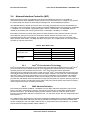
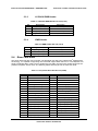
Table 12. Power Supply Signal Connector Pin-out (J1K1)
44
Pin
Signal
1
SMB_CLK_ESB_FP_PWR_R
Color
Orange
2
SMB_DAT_ESB_FP_PWR_R
Black
3
SMB_ALRT_3_ESB_R
Red
4
3.3V SENSE-
Yellow
5
3.3V SENSE+
Green
Revision 1.7
Intel order number: D31979-010