1
R
O-T L
Tested and
Listed by
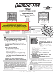
TOPAZ
C
Portland
Oregon USA
US
OMNI-Test Laboratories, Inc.
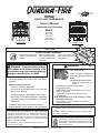
DIRECT VENT ROOM HEATER
Owner’s Manual
Installation and Operation
Model:
839-1290
839-1320
839-1340
844-4120
TOPAZ-D-CSB
Quartet Front
Solitaire Front
CAUTION
DO NOT DISCARD THIS MANUAL
• Important operating and • Read, understand and • Leave this manual with
follow these instructions
maintenance instructions
party responsible for use
for safe installation and
included.
and operation.
operation.
WARNING: If the information in these
instructions is not followed exactly, a fire
or explosion may result causing property
damage, personal injury, or death.
• Do not store or use gasoline or other flammable
vapors and liquids in the vicinity of this or any other
appliance.
• What to do if you smell gas
- Do not try to light any appliance.
Do not touch any electrical switch. Do not use any
phone in your building.
- Immediately call your gas supplier from a neighbor’s phone. Follow the gas supplier’s instructions.
- If you cannot reach your gas supplier, call the fire
department.
• Installation and service must be performed by a
qualified installer, service agency, or the gas supplier.
This appliance may be installed as an OEM installation in
manufactured home (USA only) or mobile home and must be
installed in accordance with the manufacturer's instructions
and the manufactured home construction and safety standard,
Title 24 CFR, Part 3280 or Standard for Installation in Mobile
Homes, CAN/CSA Z240MH.
This appliance is only for use with the type(s) of gas indicated on the rating plate.
D
DI O N
SC O
AR T
D
WARNING
HOT SURFACES!
Glass and other surfaces are
hot during operation AND cool
down.
Hot glass will cause burns.
• Do not touch glass until it is
cooled
• NEVER allow children to touch glass
• Keep children away
• CAREFULLY SUPERVISE children in the same
room as appliance
• Alert children and adults to hazards of high
temperatures
High temperatures may ignite clothing or other
flammable materials.
• Keep clothing, furniture, draperies and other
combustibles away.
In the Commonwealth of Massachusetts:
• installation must be performed by a licensed plumber or gas
fitter.
See Table of Contents for additional Commonwealth of Massachusetts requirements.
Installation and service of this appliance should be
performed by qualified personnel. Hearth & Home
Technologies suggests NFI certified or factory-trained
professionals, or technicians supervised by an NFI
certified professional.
Quadra-Fire • Topaz • 7009-113 Rev. i • 6/11
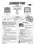
and Welcome to the Quadra-Fire Family!
Hearth & Home Technologies welcomes you to our tradition
of excellence! In choosing a Quadra-Fire appliance, you
have our assurance of commitment to quality, durability,
and performance.
of our stoves, inserts and fireplaces. And yet we are oldfashioned when it comes to craftsmanship. Each appliance
is meticulously fabricated and gold and nickel surfaces are
hand-finished for lasting beauty and enjoyment. Our pledge
to quality is completed as each model undergoes a quality
control inspection.
This commitment begins with our research of the market,
including ‘Voice of the Customer’ contacts, ensuring we
make products that will satisfy your needs. Our Research
and Development facility then employs the world’s most
advanced technology to achieve the optimum operation
We wish you and your family many years of enjoyment in
the warmth and comfort of your hearth appliance. Thank
you for choosing Quadra-Fire.
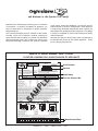
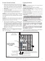
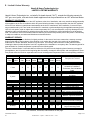
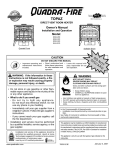
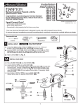
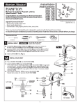
SAMPLE OF SERIAL NUMBER / SAFETY LABEL
LOCATION: HANGING ON A CHAIN ON BACK OF APPLIANCE
Portland
Report No. / Rapport Numéro
061-S-19B-5
SERIAL NO.
MODEL / MODÈLE: TOPAZ
Serial Number
1445 North HIghway
Colville, WA 99114
www.quadrafire.com
VENTED GAS FIREPLACE HEATER FOURNAISE AU GAZ AVEC
VENTILATION. NOT FOR USE WITH SOLID FUEL / NE PAS UTILISER
AVEC LE COMBUSTIBLE SOLIDE.
Barcode
APPROVED FOR CANADA AND USA TO:
ANSI Z21.88a-2000 / CSA 2.33a-M-00 Vented Gas Fireplace Heaters, and
applicable sections of UL307b Gas Burning Heating Appliances for
Manufactured Homes and Recreational Vehicles, CAN/CGA 2.17-M91
“Gas Fired Appliances for use at High Altitudes.” This appliance is
manufactured for operation with Natural Gas.
FAN TYPE VENTED CIRCULATOR / VENTILATEUR CIRCULATOIRE
Blower Electrical Rating / Évaluation du Ventilateur Électrique:
115 V., 1.5 Amps, 60 Hz, 150 Watts
APPROUVÉ POUR LE CANADA ET LES ÉTATS-UNIS:
ANSI Z21.88a-2000 / CSA 2.33a-M-00 Fournaises au Gaz avec Ventilation,
et les sections applicable de UL 307b Appareils de Chauffage Au Gaz pour
les Maisons Mobiles et les Véhicules Motorisés, CAN/CGA 2.17-M91 “Gas
Fired Appliances for use at High Altitudes”.
Cet appareil est manufacturé pour l’opération avec le Gaz Naturel.
Thermal Efficiency / Efficacité Thermique*
85% NG (blower on / avec ventilateur allumé)
85% LP (blower on / avec ventilateur allumé)
* With Maximum horizontal length. / Avec longueur horizontale maximum.
Test Lab & Report No.
P.4.1-02 Canada Minimum pipe (P.4.1-02 Le canada tuyau minimum) 62.98% NG / 64.14% LP
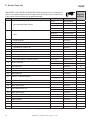
For use with Propane
Usage au Gaz Propane
0-2000’
38,000
30,500
32,500
.073” (49DMS)
11“
14”
10”
E
For use with Natural Gas
Usage au Gaz Naturel
Top Vent/Rear Vent:
0-2000’
Input Rate on “HI” (BTU/Hr)
39,500
Input Rate on “LO” (BTU/Hr)
26,500
Maximum Output (BTU/Hr)**
33,600
Main Burner Orifice (DMS)
.125”
Minimum Inlet Pressure (Inches W.C.)
4.5“
Maximum Inlet Pressure (Inches W.C.)
7.0”
Manifold Pressure on “HI” (Inches W.C.)
3.5”
**Max Venting, Blower On
Model Name
PL
Bouche Supérieure/Conduit postérieur:
Puissance Évaluée à “HI” (BTU/Hr)
Puissance Évaluée à “LO” (BTU/Hr)
Puissance Maximum (BTU/Hr)**
Orifice du Brûleur Principal
Pression Minimum de la Valve (pouces W.C.)
Pression Maximum de la Valve (pouces W.C.)
Pression du Collecteur d’ Échappement à “HI” (pouces W.C.)
** Ventilation Maximum, Ventilateur Allumé
SA
M
This appliance equipped only for altitudes 0-2000’ (0-610m) in USA; and in Canada for altitudes of 0-4500’ (0-1370m). In USA for Altitudes above 2000’, the vent
configuration, orifice, or combination of both may need to be changed. See Owner’s Manual for information on making these changes.
This appliance must be installed in accordance with local codes, if any (and Commonwealth of Massachusetts approved); if none, follow National Fuel Gas Code ANSI Z223.1,
or Canadian Installation Codes, CAN/CGA-B149 in Canada. Install and use only in accordance with manufacturer’s installation and operating instructions. NOTE: Have the gas
supply line installed in accordance with local building codes by a qualified installer approved and/or licensed as required by the locality. (In the Commonwealth of Massachusetts, installation
must be performed by a licensed plumber or gas fitter.)
Cet appareil est équipé pour les altitudes de 0-2000’ (0-610m) aux États-Unis; et au Canada pour les altitudes de 0-4500’ (0-1370m). Pour les altitudes au dessus de 2000’
aux États-Unis, la configuration du ventilateur, son orifice ou les deux peuvent possiblement avoir à être changé. Voyez le manuel du propriétaire pour les informations sur
ces changements. Cet appareil doit être installé en accord avec les codes locaux, s’il-y-a lieu (et approuvé par dans la République de Massachusetts); sinon lisez au National
Fuel Gas Code ANSI Z223.1, ou aux code courant d'installation Installez et utilisez en accords avec les instructions d’installation et d’opération du manufacturier. REMARQUE:
Le conduit gaz doit être installé conformément aux codes de construction locaux. L'installation doit être effectuée par un technicien qualifeé et/ou muni d'une licence de manière à
respecter les règlements municipaux. (Dans la République de Massachusetts, l'installation doit être effectuée par un plombier ou un installateur d'appareils à gaz agrée.)
This appliance must be installed in accordance with the current Standard CAN/CSA Z240 MH, Mobile Housing or with Manufactured Home Construction and Safety Standard,
Title 24 CFR, Part 3280, or when such standard is not applicable, ANSI/NCSBCS A225.1/NFPA 501A, Manufactured Home Installation Standard.
WARNING: Do not operate the appliance until all sections have been assembled and installed in accordance with the manufacturer's instructions.
Installer l'appareil selon la norme CAN/CSA-Z240, Série MM, Maisons mobiles ou la norme 24 CFR Part 3280, Manufactured Home Construction and Safety Standard. Si ces
normes ne sont pas pertinentes, utilisez la norme ANSI/NCSBCS A225.1/NFPA 501A, Manufactured Home Installations Standard.
AVERTISSEMENT: Ne pas utiliser l'appareil tant que toutes les sections n'ont pas ete assemblees et installees selon les instructions du fabricant.
This appliance must be properly connected to a venting system in accordance with the manufacturer's installation instructions.
Cet apprareil doit être correctement raccordé à un système d'évacuation, conformément aux instructions du fabricant
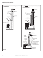
F
G
C
A
B
A
D
E
C
A
A
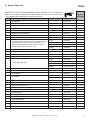
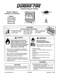
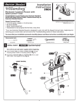
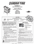
A. Side of stove top to side wall
B. Rear of stove top to back wall
C. Corner of stove top to side wall
D. Minimum Alcove Height
E. Maximum Alcove Depth
F. Minimum Alcove Width
G. Mantle clearance from stove top
6.5" (152 mm)
6" (100 mm)
1" (152 mm)
54" (1372 mm)
36" (914 mm)
40"(915 mm)
23"(584mm)
Du coté du poêle au coté du mur
Le contrôle arrière au mur arrière
Du Coin du poêle du mur
Hauteur minimum du plancher au plafond
Profondeur maximale de l'alcôve
Largeur minimum de l'alÔve
Espace libre du poêle au manteau
HEARTH: A non-combustible hearth pad is not required. However, the floor beneath the stove must be stable, level, and strong enough to support the stove without a tipping hazard.
CHEMINÉE: Un coussinet non-combustible de cheminée n’est pas exigé. Cependant, le plancher en dessous du poêle doit être droit, à niveau et assez fort pour
supporter le poêle sans le hasard de basculer.
Date of Manufacture / Date du Manufacturier
2008
2009
2010
Jan
Feb
Mar
Apr
May
DO NOT REMOVE THIS LABEL / NE PAS ENLEVER L’ÉTIQUETTE
2
Jun
Jul
Aug
Sep
Oct
Made in U.S.A. / Fait Aux États-Unis
Nov
Dec
Manufactured Date
250-7141
Quadra-Fire • Topaz • 7009-113 Rev. i • 6/11
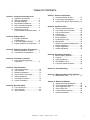
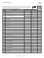
- TABLE OF CONTENTS Section 1: Listing and Code Approvals
A. Appliance Certifications ......................4
B. Glass Specifications ............................4
C. BTU Specifications ..............................4
D. High Altitude Installations ....................4
E. Non-Combustible Materials .................4
F. Combustible Materials ........................4
G. Requirements for the
Commonwealth of Massachusetts ......5
Section 2: Getting Started
A. Design & Installation
Considerations ....................................6
B. Tools and Supplies Needed................6
C. Inspect Appliance & Components .......6
Section 3: Appliance Location & Clearances
A. Selecting Appliance Location..............7
B. Clearances to Combustibles ...............7
Section 4: Termination Locations
A. Vent Termination Minimum
Clearances..........................................8
Section 5: Vent Information
A. Venting Components ..........................10
B. Use of Elbows .....................................10
C. Measuring Standards ..........................10
D. How to Use the Vent Graph ................11
E. Venting Guidelines ..............................11
F. Horizontal Termination ........................12
G. Vertical Termination ............................15
Section 6: Gas Information
A. Fuel Conversions ................................23
B. Gas Pressures ....................................25
C. Gas Connection.. ................................26
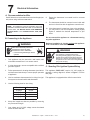
Section 7: Electrical Information
A. Recommendation for Wire ..................27
B. Connecting to the Appliance ...............27
C. Standing Pilot Ignition System Wiring ..27
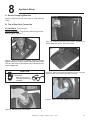
Section 8: Appliance Setup
A. Remove Shipping Materials ................29
B. Top to Rear Vent Conversion .............29
C. Leg Leveling System ...........................30
D. Accessories .........................................30
E. Front Installation .................................31
F. Brick Installation ..................................31
G. Positioning the Logs ............................32
H. Mineral Wool .......................................33
I. Glass Door Assembly Replacement ...34
J. Blower Installation ...............................34
K. Damper Adjustment ............................36
L. Shutter Adjustment .............................36
Section 9: Operating Instructions
A. Before Lighting Appliance ...................37
B. Controls ...............................................37
C. Lighting Appliance ...............................38
D. After Appliance is Lit ...........................39
E. Frequently Asked Questions ...............39
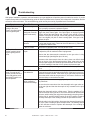
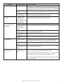
Section 10: Troubleshooting ...............................40
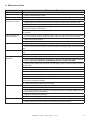
Section 11: Maintaining & Servicing Appliance
A. Maintenance Tasks .............................43
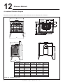
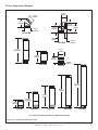
Section 12: Reference Materials
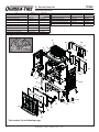
A. Appliance Dimension Diagram ...........44
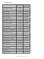
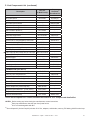
B. Vent Components Diagram ................45
C. Vent Components List ........................46
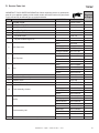
D. Service Parts List ................................48
E. Limited Lifetime Warranty ...................54
F. Contact Information ............................56
Quadra-Fire • Topaz • 7009-113 Rev. i • 6/11
3
1
Listing and Code Approvals
C. BTU Specifications
A. Appliance Certification
MODEL:
Model
Topaz
LABORATORY:
OMNI Test Laboratories, Inc.
061-S-24-5
TYPE:
Direct Vent Gas Heater
STANDARD:
ANSI Z21.88a-2000ּCSA 2.33a-M00ּ
UL307bּCAN/CBA 2.17-M91
The product is listed to ANSI standards for “Vented Gas
Appliance Heaters” and applicable sections of “Gas Burning
Heating Appliances for Manufactured Homes and Recreational Vehicles” and "Gas Fired Appliances for use at High
Altitudes".
Manufactured Home or Mobile Home installation may occur
only after the home is site located and must conform with
the Manufactured Home Construction and Safety Standard,
Title 24 CFR, Part 3280, or, when such a standard is
not applicable, the Standard for Manufactured Home
Installations, ANSI/NCSBCS A225.1, or Standard for Gas
Equipped Recreational Vehicles and Mobile Housing, CSA
Z240.4.
When installed, the appliance must be electrically grounded
in accordance with local codes or, in the absence of local
codes, with the National Electrical Code, ANSI/NFPA 70, or
the Canadian Electrical Code, CSA C22.1.
B. Glass Specifications
This appliance is equipped with 5mm ceramic glass. Replace
glass only with 5mm ceramic glass. Please contact your
dealer for replacement glass.
NOTE: This installation must conform with local codes. In the
absence of local codes you must comply with the National
Fuel Gas Code, ANSI Z223.1-latest edition in the U.S.A.
and the CAN/CGA B149 Installation Codes in Canada.
(US or Canada)
Topaz (NG)
Maximum
Input BTU
Minimum
Input
BTU
Orifice
Size
*Efficiency
Up To
**P.4
%
39,500 26,500
.125
85
63
Topaz (LP) 38,000 30,500 .073
85
* Thermal efficiency maximum pipe with blower on.
** Canada minimum pipe.
D. High Altitude Installations
Omni-Test Laboratories listed gas appliances are tested and
approved without requiring changes for elevations from 0 to
2000 feet in the U.S.A. and 0 to 4500 feet in Canada.
When installing this appliance at an elevation above 2000
feet, it may be necessary to decrease the input rating by
changing the existing burner orifice to a smaller size. Input
rate should be reduced by 4% for each 1000 feet above a
2000 foot elevation in the U.S.A. If the heating value of the
gas has been reduced, these rules do not apply. To identify
the proper orifice size, check with the local gas utility.
If installing this appliance at an elevation above 4500 feet (in
Canada), check with local authorities.
E. Non-Combustible Materials
Materials that are reported as passing ASTM E 136,
Standard Test Method for Behavior of Materials in a
Vertical Tube Furnace at 750°C, shall be considered noncombustible materials.
F. Combustible Materials
Materials made of or surfaced with wood, compressed
paper, plant fibers, plastics, or other materials that can ignite
and burn, whether flame proofed or not, or whether plastered
or unplastered shall be considered combustible materials.
WARNING
Do NOT use this appliance if any part has been under water.
Immediately call a qualified service technician to inspect
the unit and to replace any part of the control system and
any gas control which has been under water.
4
64
Quadra-Fire • Topaz • 7009-113 Rev. i • 6/11
NOTE: The following requirements reference various
Massachusetts and national codes not contained in this
document.
G. Requirements for the Commonwealth of
Massachusetts
For all side wall horizontally vented gas fueled equipment
installed in every dwelling, building or structure used in whole
or in part for residential purposes, including those owned or
operated by the Commonwealth and where the side wall
exhaust vent termination is less than seven (7) feet above
finished grade in the area of the venting, including but not
limited to decks and porches, the following requirements
shall be satisfied:
Installation of Carbon Monoxide Detectors
At the time of installation of the side wall horizontal vented
gas fueled equipment, the installing plumber or gas fitter shall
observe that a hard wired carbon monoxide detector with an
alarm and battery back-up is installed on the floor level where
the gas equipment is to be installed. In addition, the installing
plumber or gas fitter shall observe that a battery operated
or hard wired carbon monoxide detector with an alarm is
installed on each additional level of the dwelling, building or
structure served by the side wall horizontal vented gas fueled
equipment. It shall be the responsibility of the property owner
to secure the services of qualified licensed professionals for
the installation of hard wired carbon monoxide detectors.
Inspection
The state or local gas inspector of the side wall horizontally
vented gas fueled equipment shall not approve the installation unless, upon inspection, the inspector observes carbon
monoxide detectors and signage installed in accordance with
the provisions of 248 CMR 5.08(2)(a) 1 through 4.
Exemptions
The following equipment is exempt from 248 CMR 5.08(2)
(a) 1 through 4:
• The equipment listed in Chapter 10 entitled “Equipment
Not Required To Be Vented” in the most current edition of
NFPA 54 as adopted by the Board; and
• Product Approved side wall horizontally vented gas fueled
equipment installed in a room or structure separated from
the dwelling, building or structure used in whole or in part
for residential purposes.
MANUFACTURER REQUIREMENTS
Gas Equipment Venting System Provided
When the manufacturer of Product Approved side wall
horizontally vented gas fueled equipment provides a venting system design or venting system components with the
equipment, the instructions provided by the manufacturer for
installation of the equipment and the venting system shall
include:
• Detailed instructions for the installation of the venting system design or the venting system components; and
In the event that the side wall horizontally vented gas fueled
equipment is installed in a crawl space or an attic, the hard
wired carbon monoxide detector with alarm and battery backup may be installed on the next adjacent floor level.
• A complete parts list for the venting system design or
venting system.
In the event that the requirements of this subdivision can not
be met at the time of completion of installation, the owner shall
have a period of thirty (30) days to comply with the above
requirements; provided, however, that during said thirty (30)
day period, a battery operated carbon monoxide detector with
an alarm shall be installed.
When the manufacturer of a Product Approved side wall horizontally vented gas fueled equipment does not provide the
parts for venting the flue gases, but identifies “special venting systems”, the following requirements shall be satisfied by
the manufacturer:
Approved Carbon Monoxide Detectors
Each carbon monoxide detector as required in accordance
with the above provisions shall comply with NFPA 720 and
be ANSI/UL 2034 listed and IAS certified.
Signage
A metal or plastic identification plate shall be permanently
mounted to the exterior of the building at a minimum height
of eight (8) feet above grade directly in line with the exhaust
vent terminal for the horizontally vented gas fueled heating
appliance or equipment. The sign shall read, in print size no
less than one-half (1/2) inch in size, “GAS VENT DIRECTLY
BELOW. KEEP CLEAR OF ALL OBSTRUCTIONS.”
Gas Equipment Venting System NOT Provided
• The referenced “special venting system” instructions shall
be included with the appliance or equipment installation
instructions; and
• The “special venting system” shall be Product Approved
by the Board, and the instructions for that system shall
include a parts list and detailed installation instructions.
A copy of all installation instructions for all Product Approved
side wall horizontally vented gas fueled equipment, all venting instructions, all parts lists for venting instructions, and/
or all venting design instructions shall remain with the appliance or equipment at the completion of the installation.
See Gas Connection section for additional Commonwealth of Massachusetts requirements.
Quadra-Fire • Topaz • 7009-113 Rev. i • 6/11
5
2
Getting Started
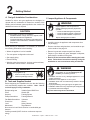
A. Design & Installation Considerations
Quadra-Fire direct vent gas appliances are designed to
operate with all combustion air drawn from outside of the
building and all exhaust gases expelled to the outside. No
additional air source is required.
CAUTION
Check building codes prior to installation.
• Installation MUST comply with local, regional, state
and national codes and regulations.
• Consult local building, fire officials or authorities having
jurisdiction about restrictions, installation inspection,
and permits.
C. Inspect Appliance & Components
WARNING
Inspect appliance and components for
damage. Damaged parts may impair safe
operation.
• Do NOT install damaged components.
• Do NOT install incomplete components.
• Do NOT install substitute components.
Report damaged parts to dealer.
• Carefully remove the appliance and components from
the packaging.
When planning an installation, it is necessary to determine
the following information before installing:
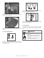
• Remove cast door and glass door, and set aside on protective surface. See page 34.
• Where the appliance is to be installed.
• Remove log set and component pack from firebox.
• The vent system configuration to be used.
• Report to your dealer any parts damaged in shipment,
particularly the condition of the glass.
• Gas supply piping.
• Electrical wiring.
• Whether optional accessories - devices such as a blower,
thermostat or remote control - are desired.
WARNING
WARNING
Keep appliance dry.
• Mold or rust may cause odors.
• Water may damage controls.
B. Tools and Supplies Needed
Before beginning the installation be sure that the following
tools and building supplies are available. Note: Not all
tools will apply to every installation.
Reciprocating saw
Variable Speed Drill/Driver
Pliers
Wrench Set
Hammer
Framing Square
Phillips Screwdriver
Framing Material
Flat Blade Screwdriver Voltmeter
Plumb Line
Gloves
Level
Safety Glasses
Manometer
Tape Measure
Non-corrosive Leak Check Solution or combustible gas
detector
Caulking material (300ºF minimum continuous exposure
rating)
6
• Read all of the instructions before starting the installation. Follow these instructions carefully during the
installation to ensure maximum safety and benefit.
Hearth & Home Technologies disclaims any
responsibility for, and the warranty will be
voided by, the following actions:
• Installation and use of any damaged appliance or vent
system component.
• Modification of the appliance or vent system.
• Installation other than as instructed by Hearth & Home
Technologies.
• Improper positioning of the gas logs or the glass door.
• Installation and/or use of any component part not approved
by Hearth & Home Technologies.
Any such action may cause a fire hazard.
Quadra-Fire • Topaz • 7009-113 Rev. i • 6/11
3
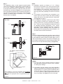
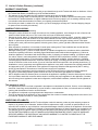
Appliance Location and Clearances
NOTE:
· Illustrations reflect typical installations and are FOR
DESIGN PURPOSES ONLY.
· Illustrations/diagrams are not drawn to scale.
· Actual installation may vary due to individual design
preference.
WARNING
Fire Risk
Provide adequate clearance:
• Around air openings
• To combustibles
• For service access
Locate appliance away from traffic areas.
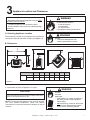
A. Selecting Appliance Location
WARNING
When selecting a location for your appliance it is important to
consider the required clearances to walls (see Figure 3.1).
Fire Risk.
• Locate and install appliance to all
clearance specifications in manual.
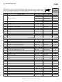
B. Clearances
F
C
D
G
B
A
A
E
A
A
C
Model
Topaz
A
B
C
D
E
F
G
Inches
6-1/2
6
1
54
36
40
23
Millimeters
165
152
25
1372
914
1016
584
Figure 3.1
It is permissible to place the appliance on carpet.
WARNING
CAUTION
Some carpet materials may be sensitive to radiant heat from the
appliance causing discoloration or odor.
NOTE: Flooring beneath appliance may reach 90 degrees
plus room ambient temperature. Check with flooring
manufacturer for maximum temperature allowed on flooring
surfaces.
Fire Risk.
Odor Risk.
Tipping Risk
• Install appliance on a stable, level platform/
floor strong enough to support appliance
without tipping.
•
USE wood flooring, ceramic tile, brick hearth
or high pressure laminate flooring applied
directly over the sub-flooring material.
Quadra-Fire • Topaz • 7009-113 Rev. i • 6/11
7
4
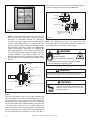
Termination Locations
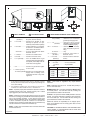
A. Vent Termination Minimum Clearances
HORIZONTAL
OVERHANG
WARNING
Fire Risk.
Explosion Risk.
Maintain vent clearance to combustibles
as specified.
• Do not pack air space with insulation or
other materials.
Failure to keep insulation or other materials
away from vent pipe may cause fire.
2 FT.
MIN.
20 INCHES MIN.
VERTICAL
WALL
LOWEST
DISCHARGE
OPENING
GAS DIRECT VENT
TERMINATION CAP
X
12
ROOF PITCH
IS X/ 12
Measure vertical clearances from this surface.
H (MIN.) - MINIMUM HEIGHT FROM ROOF
TO LOWEST DISCHARGE OPENING
Measure horizontal clearances from this surface.
(See Figure 4.4 for specific clearances.)
Figure 4.1 Termination Clearances
A
B
6 in. (minimum) up to 20 in.
152 mm/508 mm
18 in. minimum
457 mm
20 in. and over
0 in. minimum
Roof Pitch
H (Min.) Ft.
Flat to 6/12 ......................................................... 1.0*
Over 6/12 to .......................................................
7/12
. 1.25*
Over 7/12 to 8/12 ............................................... 1.5*
Over 8/12 to 9/12 ............................................... 2.0*
Over 9/12 to 10/12 ............................................. 2.5*
Over 10/12 to 11/12 ........................................... 3.25
Over 11/12 to 12/12 ........................................... 4.0
Over 12/12 to 14/12 ........................................... 5.0
Over 14/12 to 16/12 ........................................... 6.0
Over 16/12 to 18/12 ........................................... 7.0
Over 18/12 to 20/12 ........................................... 7.5
Gas, Wood or Fuel Oil
Termination Cap
Figure 4.3 Minimum Height from Roof to Lowest Discharge
Opening
B
Figure 4.3 specifies minimum vent heights for various
pitched roofs.
A*
Gas
Termination
Cap **
*
**
If using decorative cap cover(s), this distance may need to be
increased. Refer to the installation instructions supplied with the
decorative cap cover.
In a staggered installation with both gas and wood or fuel oil
terminations, the wood or fuel oil termination cap must be
higher than the gas termination cap.
Figure 4.2 Multiple Vertical Termination
8
Quadra-Fire • Topaz • 7009-113 Rev. i • 6/11
M
N
P
G
R
v
A
D
H
Q
(See Note 2)
E
v
V
B
L
v
v
F
v
U.S.
(3 FT)
B
B
v
V
v
I
M
A
V = VENT TERMINAL
A
B
D*
= 12 inches ............. clearances above grade, veran(See Note 1)
da, porch, deck or balcony
= 12 inches ............ clearances to window or door
that may be opened, or to permanently closed window. (Glass)
= 18 inches ............. vertical clearance to unventilated soffit or to ventilated soffit located above the terminal
*30 inches ............ for vinyl clad soffits and below
electrical service
= 9 inches .............. clearance to outside corner
G
= 6 inches ............... clearance to inside corner
H
= 3 ft. (Canada) ...... not to be installed above a gas
meter/regulatorassembly within 3
feet (90cm) horizontally from the
center-line of the regulator
J
= 3 ft. ....................... clearance to gas service regulator vent outlet
= 9 inches (U.S.A.)
12 inches (Canada)clearance to non-mechanical air
supply inlet to building or the
combustion air inlet to any other
appliance
v
*** only permitted if veranda, porch, deck or balcony is fully open on
a minimum of 2 sides beneath the floor, or meets Note 2.
S
V
V
= AREA WHERE TERMINAL IS NOT PERMITTED
K
= 3 ft. (U.S.A.)
6 ft. (Canada) ......... clearance to a mechanical
(powered) air supply inlet
L** = 7 ft. ......................... clearance above paved
(See Note 1)
sidewalk or a paved driveway
located on public property
M*** = 18 inches .............. clearance under veranda ,
porch, deck, balcony or overhang
42 inches .............. vinyl
S =
6 inches ................. clearance from sides of
(See Note 3)
electrical service
T = 12 inches ................ clearance above electrical
service
(See Note 3)
Alcove Applications
N
P
= 6 inches ................. non-vinyl sidewalls
12 inches ............... vinyl sidewalls
= 8 ft.
QMIN
RMAX
1 cap
3 feet
2 x Q ACTUA L _
___________________________________________________________________
2 caps
6 feet
1 x Q ACTUA L _
___________________________________________________________________
3 caps
9 feet
2/3 x Q ACTUA L _
___________________________________________________________________
4 caps
12 feet
QMIN = # termination caps x 3
** a vent shall not terminate directly above a sidewalk or paved
driveway which is located between two single family dwellings and
serves both dwellings.
Electrical
Service
D*
X
J or K
X = AIR SUPPLY INLET
F
I
T
S
1/2 x Q ACTUA L
RMAX = (2 / # termination caps) x QACTUAL
NOTE:
Local codes or regulations may require different
clearances.
NOTE: Termination caps may be hot. Consider their proximity to
doors or other traffic areas.
NOTE 1: On private property where termination is less than 7 feet above
a sidewalk, driveway, deck, porch, veranda or balcony, use of a listed
cap is suggested. (See vents components pages.)
WARNING: In the U.S.: Vent system termination is NOT permitted
in screened porches. You must follow side wall, overhang and
ground clearances as slated in the instructions.
NOTE 2: Termination in an alcove space (spaces only open on one side
and without an overhang) are permitted with the dimensions specified for
vinyl or non-vinyl siding and soffits. 1. There must be at least 3 feet
minimum between termination caps. 2. All mechanical air intakes within
10 feet of a termination cap must be a minimum of 3 feet below the
termination cap. 3. All gravity air intakes within 3 feet of a termination cap
must be a minimum of 1 foot below the termination cap.
In Canada: Vent system termination is NOT permitted in screened
porches. Vent system termination is permitted in porch areas with
two or more sides open. You must follow side wall, overhang and
ground clearances as stated in the instructions.
NOTE 3: Location of the vent termination must not interfere with access
to the electrical service.
Figure 4.4
Quadra-Fire assumes no responsibility for the improper performance of the appliance when the venting system does not meet
these requirements.
CAUTION: IF EXTERIOR WALLS ARE FINISHED WITH
VINYL SIDING, IT IS SUGGESTED THAT A VINYL PROTECTOR KIT BE INSTALLED.
Quadra-Fire • Topaz • 7009-113 Rev. i • 6/11
9
5
Vent Information
A. Venting Components
B. Use of Elbows
In order to comply with applicable codes and product
warranties, use only following venting components:
•
•
•
•
•
CAUTION
Hearth & Home Technologies (HHT)
Simpson Dura-Vent
Selkirk Direct-Temp
Amerivent Direct
Security Secure Vent
ALL vent configuration specifications MUST be followed.
• This product is tested and listed to these
specifications.
• Appliance performance will suffer if specifications are
not followed.
DO
NOT
USE
FIELD-FABRICATED
VENTING
COMPONENTS. Refer to the venting manufacturer’s
instructions.
This product is approved to be vented either horizontally,
through the side wall or vertically through the roof. You may
vent through a Class A or masonry chimney if an approved
adapter is used.
Diagonal runs have both vertical and horizontal vent aspects
when calculating the effects. Use the rise for the vertical
aspect and the run for the horizontal aspect. (See Figure 5.1.)
Two 45° elbows may be used in place of one 90° elbow. On
45° runs, one foot of diagonal is equal to 8-1/2 in. (216mm)
horizontal run and 8-1/2 in. (216mm) vertical run. A length of
straight pipe is allowed between two elbows. (See Figure 5.1.)
Vertical
•
A support box or ceiling firestop is required when the
venting passes through a ceiling.
•
Roof flashing and a storm collar are required when
venting passes through the roof.
•
Follow instructions provided with the venting for installation of these items.
WARNING
in
.
A round support box/wall thimble or heat shield is
required when the venting passes through a combustible wall.
12
•
8-1/2 in.
Horizontal
Figure 5.1
C. Measuring Standards
Fire Hazard.
Explosion Risk.
Asphyxiation Risk.
Do NOT connect this gas appliance to a chimney
flue serving a separate solid-fuel or gas burning
appliance.
Vertical and horizontal measurements were made using the
following standards.
•
Pipe measurements are from center line to center line.
•
Horizontal terminations are measured to the outside of
the mounting surface (flange of termination cap). See
Figure 4.1 on page 8.
•
Vertical terminations are measured to the top of the last
pipe before termination cap.
•
Horizontal pipe installed level with 1/4 in. rise.
• Vent this appliance directly outside.
• Use separate vent system for this appliance.
May impair safe operation of this appliance or
other appliances connected to the flue.
10
8-1/2 in.
This appliance is a direct vent heater. All combustion air must
come directly from the outside of the building. The vent pipe
for this unit consists of an inner and an outer pipe. The inner
pipe carries the appliance exhaust out of the system, and the
outer pipe brings fresh combustion air into the appliance.
Quadra-Fire • Topaz • 7009-113 Rev. i • 6/11
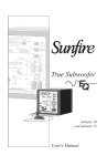
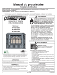
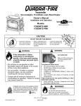
D. How to Use the Vent Graph
E. Venting Guidelines
1.
NOTES
The maximum horizontal vent run is 20 ft. (6m) when the
vertical vent rise is 10 ft. (3m).
The minimum horizontal vent run is 6 in. (152mm)
Horizontal sections require a 1/4 in. (6mm) rise for every 12
in. (305mm) of horizontal travel.
Exterior Vent Diameter = 6-5/8 in. (168mm); Inner Vent
Diameter = 4 in. (102mm).
Horizontal sections require noncombustible support every 3
ft. (914mm), e.g. wall straps.
For any vertical termination a minimum of 6 ft. (2m) vertical
must be used.
2.
3.
Measure the vertical distance from the center line of the
flue pipe to the center of the 90° elbow. On the graph
below, draw a horizontal line from that measurement
on the vertical axis across until it intersects with the
slanted line.
From the point of this intersection, draw a vertical line to
the bottom of the graph.
The point at which this line meets the bottom line of the
graph is the maximum length of the horizontal run.
EXAMPLE 1: If the vertical dimension from the center line
of the flue vent to the center of the 90° elbow is 7 ft. (2m),
the horizontal run to the outer wall flange must not exceed
16 ft. (5m).
EXAMPLE 2: If the vertical dimension from the center line
of the flue vent is 21ft. (6m), the horizontal run to the outer
wall flange must not exceed 12 ft. 10 in. (4m).
4. Each 90° elbow is equivalent to 3 ft. (914mm) of vent
pipe and each 45° elbow is equivalent to 1ft. (305mm)
of vent pipe, and must be subtracted from the vent pipe
run. A single horizontal to vertical 90° elbow is already
calculated into the allowable 20 ft. (6m) run. Each
additional 90° elbow reduces the maximum horizontal
distance by 3 ft. (914mm).
EXAMPLE: The use of 3 elbows would reduce the allowable
horizontal run to 9 ft. (3 -1 = 2 elbows x 3 ft. = 6 ft.; 20 ft.
max. - 6 ft. = 14 ft. max.).
40 ft. (12m)
Maximum Vertical
EXCEPTIONS FOR HORIZONTAL INSTALLATIONS:
*When installing the Topaz in a rear vent configuration
with no vertical rise, a Snorkel Kit must be used.
*The maximum horizontal vent run is 3 ft. (914mm).
*The maximum horizontal vent run with a 45° elbow is 2
ft. (609mm).
*The minimum horizontal vent run is 6 in. (152mm).
INDIVIDUAL INSTALLATIONS MAY VARY. PERCENTAGE
CLOSED BASED ON FULL RANGE OF DAMPER
TRAVEL.
NOTE: If your installation falls within the gray-shaded
area on graph, see information on VERTICAL DAMPER
ADJUSTMENT in Section 8.
*In the Commonwealth of Massachusetts, the word damper
shall be replaced with the words flue restrictor.
40'
39'
38'
37'
36'
35'
34'
32'
30'
28'
26'
24'
Example 2
Damper position
more CLOSED in
this area
22'
20'
18'
VERTICAL DISTANCE
FROM APPLIANCE TO
90° ELBOW
16'
Damper position
more OPEN in
this area
14'
12'
10'
Example 1
8'
No damper
in this area
6'
4'
2'
2'
6 in. (152mm) Minimum
Vertical Termination
C
L
C For
L
rear vent or top of
appliance for top vent
4'
6'
8'
10'
12'
14' 15' 16' 17' 18' 19' 20'
3 ft. (914mm) Maximum Horizontal run with no
vertical pipe and with 1/4 in (6mm) rise per foot.
Must use Snorkel cap.
6 in. (152mm) Minimum starter pipe
Figure 5.2
Quadra-Fire • Topaz • 7009-113 Rev. i • 6/11
11
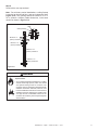
F. Horizontal Termination
Type A -
WARNING
Fire Hazard.
Exhaust Fume Risk.
Impaired Performance of Appliance.
Up & Out Installations for Top Vent
Configurations
Wall Thimble
• Ensure vent components are locked together correctly.
90º Degree
Elbow
• Pipe may separate if not properly joined.
Termination Cap
Wall Thimble Cover
Pipe Length
Pipe Length
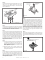
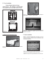
Step 2.
Direct vent pipe is designed with a locking connection. To
connect the venting system to the appliance flue outlet, a
twist-lock adapter is built into the appliance at the factory.
Wall thickness may vary. Remember to include wall
thickness in minimum clearances when figuring venting
lengths for your installation needs.
Note: Female ends of direct vent pipe/elbows are
designed to slide straight onto the male ends of adjacent
pipes by orienting the pipe indentations so they match and
slide into the entry slots on the male ends, see Figure 5.4.
Push the pipe sections completely together, then twist-lock
one section clockwise approximately one-quarter turn, until
the two sections are fully locked. The female locking lugs
may not be visible from the outside. They may be located by
examining the inside of the female ends.
Type B -
Rear Installations for Use with Rear Vent
Kit
Snorkle Kit
Female Locking Lugs
Wall Thimble Cover
15-5/8 in.
(397mm)
CL
21 in.
(533mm)
Male Locking Lugs
Pipe Length
Wall Thimble
Wall Strap
14 in. (356mm) Wide
Figure 5.4
(See Section 12 for conversion kit and venting
components.) This is the only venting configuration that
requires the use of the rear vent derating orifice that
comes with the rear vent kit. NOTE: A Snorkel Kit is
required.
Figure 5.3
WARNING
Fire Risk.
Explosion Risk.
Combustion Fume Risk.
Use vent run supports per installation instructions.
Connect vent sections per installation instructions.
Step 1.
Determine the desired location of the appliance. Check to
ensure that wall studs or roof rafters are not in the way when
the venting system is attached. If this is the case, you may
want to adjust the location of the appliance.
12
• Maintain all clearances to combustibles.
• Do NOT allow vent to sag below connection
point to appliance.
• Maintain specified slope (if required).
Improper support may allow vent to sag or separate.
Quadra-Fire • Topaz • 7009-113 Rev. i • 6/11
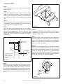
Step 3.
For installations using a round support box/wall thimble
(check pipe manufacturer's instructions), mark the wall for a
10 in. x 10 in. (254mm x 254mm) square hole. The center
of the square hole should line up with the center line of the
horizontal pipe, as shown in Figure 5.5. Cut and frame the
hole in the exterior wall where the vent will be terminated. If
the wall being penetrated is constructed of noncombustible
material, i.e. masonry block or concrete, a 7 in. (178mm)
diameter hole is acceptable.
Top Vent
Center of Hole
Center Line
Wall Thimble
Center Line
Rear Vent
Center of Hole
NOTE:
(1) Installation requires a minimum of 6 in. (152mm)
horizontal run of vent with a 1/4 in. (6mm) rise run towards
the termination. Each 1 ft. (305mm) of horizontal venting
must include a 1/4 in. (6mm) rise. Never allow the vent
to run downward. This could cause high temperatures
and may present the possibility of a house or structure
fire.
(2) The location of the horizontal vent termination on an
exterior wall must meet all local and national building
codes, and must not be easily blocked or obstructed,
see Figure 4.4 on page 9.
(3) For installations requiring a vertical rise on the exterior
of the building, a snorkel kit is available with a 14 in.
(356mm) and a 36 in. (914mm) tall snorkel termination
cap. Follow the same installation procedures as used
for standard horizontal terminations. If the snorkel
termination must be installed below grade (i.e. basement
application), proper drainage must be provided to
prevent water from entering the snorkel termination. Do
not backfill around snorkel termination.
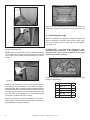
Step 4.
Position the horizontal termination cap in the center of the 10
in. x 10 in. (254mm x 254mm) square hole and run a bead
of non-hardening mastic around its outside edges, so as to
make a seal between it and the wall, attach termination cap
to the exterior wall with the four wood screws provided. The
arrow on the vent cap should be pointing up (Figure 5.6).
Center Line
Center Line
Wall Thimble
WOOD
SCREW
45° Elbow in Corner Installation
Wall Thimble
HOT
14 in. (356mm) Pipe Length
WALL THIMBLE
Max. Wall Depth
10 in. (254mm)
45°
Elbow
1 in. (25mm)
clearance from
appliance corner to
Figure 5.6
NOTES:
(1) The four wood screws provided should be replaced
with appropriate fasteners for stucco, brick, concrete,
or other types of sidings.
1 in. (25mm) clearance from appliance
corner to combustible wall
When installing in a rear vent configuration with no vertical
rise: a Snorkel Kit must be used, and a derating orifice must
be installed. The appropriate orifice is supplied with the Rear
Vent Kit.
(2) A termination cap with a built-in vinyl siding standoff is
highly recommended on a building with vinyl siding. The
pilot hole will be 2 in. (51mm) closer to the bottom of the
square than the top. Using a framing square, draw a 14
in. x 14 in. (356mm x 356mm) square around the pilot
hole in the siding. See Figure 5.7 on the next page.
Figure 5.5
Quadra-Fire • Topaz • 7009-113 Rev. i • 6/11
13
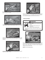
the vent pipe. Use the two sheet metal screws provided to
connect the strips to the pipe section (Figure 5.9).
8 in.
(203mm)
7 in.
1/4 in. (6mm)
(178mm)
7 in.
(178mm)
Fold Strap Here
6 in.
(152mm)
Sheet Metal Screw
Figure 5.7
Wall Thimble
Wall Thimble Cover/Ceiling
Firestop as Required by Local
Jurisdiction
Strap
(NOTE: Some termination caps may cause the vent
pipe to be off center on flashing). Ensure that proper
clearances to combustible materials are maintained.
If you are not using an approved termination cap with
a built-in vinyl siding standoff on a building with vinyl
siding, a vinyl siding standoff should be installed between
the termination cap and the exterior wall (Figure 5.8).
Follow manufacturer’s instructions for attaching the
vinyl siding standoff to the horizontal termination cap.
The vinyl siding standoff prevents excessive heat from
possibly melting the vinyl siding material. The vent
terminal cap shall not be recessed into a wall or siding.
Remove siding from the area where the standoff will be
located.
Figure 5.9
Note: The attachment from the vent pipe to the vent
termination cap must be sealed with silicone. Termination
caps shall not be recessed into a wall or siding.
WARNING
Fire Hazard.
Exhaust Fume Risk.
Impaired Performance of Appliance.
• Ensure vent components are locked together correctly.
• Pipe may separate if not properly joined.
VINYL SIDING
Apply sealant to all four sides
SCREWS
Bolt horizontal top to vinyl
standoff
WARNING
Do NOT connect a pipe section to a termination cap without
using the telescoping flue section found on the termination cap.
SCREWS
WARNING
WALL THIMBLE COVER
Vinyl siding standoff with siding beneath
removed
WALL THIMBLE
Figure 5.8
Burn Risk.
• Local codes may require installation of a cap
shield to prevent anything or anyone from
touching the hot cap.
Step 5.
Place the wall thimble cover over the pipe assembly and
slide the appliance and vent assembly towards the wall,
carefully inserting the vent pipe into the vent termination
cap assembly. It is important that the vent pipe extend into
the vent termination cap a sufficient distance so as to result
in a minimum pipe overlap of 1-1/4 in. (32mm). Secure the
connection between the vent pipe and the vent termination
cap by attaching the two sheet metal strips extending from
the vent termination cap assembly into the outer wall of
14
Quadra-Fire • Topaz • 7009-113 Rev. i • 6/11
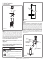
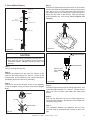
G. Vertical Termination
1. Direct Vent Pipe
Vertical Termination Cap
Storm Collar
Flashing
40 ft. (12m)
Maximum
Firestop
Support Box
Pipe Length
Figure 5.11
Step 2.
Set the gas appliance in its desired location. Drop a plumb
Figure 5.10
Step 1.
Check the installation instructions for required 1 in. (25mm)
clearances (air space) to combustibles when passing
through ceilings, walls, roofs, enclosures, attic rafters, or
other nearby combustible surfaces. See page 16, Figure
5.16. Check the instructions below for maximum vertical rise
of the venting system, and any maximum horizontal offset
limitations. All offsets must fall within the set parameters of
the vent graph (Figure 5.2) located on page 11.
NOTE: Maximum vertical rise allowable is 40 ft. (12m)
Figure 5.11).
NOTE: Maximum number of 45° elbows permitted for a
vertical installation is eight, provided their installation
does not decrease maximum allowable horizontal run (as
specified by vent graph, on page 11).
bob down from the ceiling to the position of the appliance
flue exit, and mark the location where the vent will penetrate
the ceiling. Drill a small hole at this point. Next, drop a plumb
bob from the roof to the hole previously drilled in the ceiling,
and mark the spot where the vent will penetrate the roof.
Determine if ceiling joists, roof rafters, or other framing will
obstruct the venting system. You may wish to relocate the
appliance, or to offset, as shown in Figure 5.12 to avoid
cutting loadbearing members. When location is determined,
drill small hole.
Plumber’s Tape
connected to
Wall Strap
Wall Strap
WARNING
Two 45˚ Elbows
Fire Risk.
Explosion Risk.
Maintain vent clearance to combustibles as specified.
• Do not pack air space with insulation or other
materials.
Failure to keep insulation or other materials away
from vent pipe may cause fire.
Figure 5.12
Quadra-Fire • Topaz • 7009-113 Rev. i • 6/11
15
Step 3.
To install the round support box/wall thimble cover in a flat
ceiling, cut a 10 in. (254mm) square hole in the ceiling,
centered on the hole drilled in Step 2. Frame the hole as
shown in Figure 5.13.
Shingles overlap on
top edge of flashing
CAP AND STORM
COLLAR NOT SHOWN
FOR CLARITY
Ceiling
Joists
Framing
Figure 5.14
Figure 5.13
1 - 1/2 in. (38mm) Long
Wood Screws
Step 4.
Assemble the desired lengths of pipe and elbows necessary
to reach from the appliance up through the round support
box. Ensure that all pipe and elbow connections are in their
fully twist-locked position. Assemble as instructed.
Step 5.
Cut a hole in the roof centered on the small drill hole placed in
the roof in Step 2. The hole should be of sufficient size to meet
the minimum requirements for clearance to combustibles, as
specified. Continue to assemble lengths of pipe and elbows
necessary to reach from the ceiling support box/wall thimble
up through the roof line. Galvanized pipe and elbows may
be utilized in the attic, as well as above the roofline. The
galvanized finish is desirable above the roofline, due to its
higher corrosion resistance.
NOTE:
(1) If an offset is necessary in the attic to avoid obstructions,
it is important to support the vent pipe every 3 ft.
(914mm) to avoid excessive stress on the elbows, and
possible separation. Wall straps are available for this
purpose, Figure 5.12, page 15.
Step 7.
Continue to assemble pipe sections until the height of the
vent (before adding the termination cap) meets the minimum
code requirements as outlined in the current CAN/CGAB149 Installation Codes (in Canada), the National Fuel
Gas Code NFPA 54/ANSI Z223.1 (in USA), or local codes.
Note that for steep roof pitches, the vent height must be
increased. See Roof Pitch Table (Figure 4.3, on page 8). In
high wind conditions, nearby trees adjoining rooflines, steep
pitched roofs, and other similar factors can result in poor
draft, or down drafting. In these cases increasing the vent
height or switching to the high wind termination cap may
solve this problem.
Step 8.
Slip the storm collar over the pipe, and push it down to the
top of the flashing (Figure 5.15). Use non-hardening sealant
above and below the joint between the storm collar and the
pipe.
Optional High Wind Termination Cap
Secure Flashing with Non-Hardening
Sealant and Roofing Nails
(2) Whenever possible, use 45° elbows, instead of 90°
elbows. The 45° elbow offers less restriction to the flow
of flue gases and intake air.
Step 6.
Slip the flashing over the pipe section(s) protruding through
the roof. Secure the base of the flashing to the roof with
roofing nails. Ensure the roofing material overlaps the top
edge of the flashing as shown in Figure 5.14. Verify that the
chimney is the required height above the roof. See roof pitch
table, Figure 4.3, on page 8.
16
Figure 5.15
Quadra-Fire • Topaz • 7009-113 Rev. i • 6/11
Step 9.
Twist-lock the vent cap and seal.
Note: For multi-story vertical installations, a ceiling firestop
is required at the second floor, and any subsequent floors
(Figure 5.16). The opening should be framed to 10 in. x
10 in. (254mm x 254mm) inside dimensions, in the same
manner as shown in Figure 5.13.
Nails
Ceiling Firestop
Minimum 1 in.
(25mm) Clearance
Minimum 1 in.
(25mm) Clearance
Minimum 1 in.
(25mm) Clearance
Minimum 1 in.
(25mm) Clearance
Figure 5.16
WARNING
Fire Risk.
Explosion Risk.
• Any occupied areas above the first floor, including
closets and storage spaces, which the vertical
vent passed through must be enclosed. The
enclosure may be framed and sheetrocked with
standard construction materials; however, refer
to these installation instructions for the minimum
allowable clearance between the outside of the
vent pipe and the combustible surfaces of the
enclosure. Do not fill any of the required air space
with insulation.
Quadra-Fire • Topaz • 7009-113 Rev. i • 6/11
17
2. Cathedral Ceiling
Step 1.
Follow installation Steps 1 and 2 under vertical installation
section, page 15.
Step 2.
Using the plumb-bob, mark the center line of the venting
system on the ceiling, and drill a small hole through the
ceiling and roof at this point. From the roof, locate the drill
hole and mark the outline of the cathedral ceiling support
box.
Step 3.
Remove shingles or other roof covering as necessary to cut
the rectangular hole for the support box. Cut the hole 1/8 in.
(3mm) larger than the support box outline.
Figure 5.18
Step 4.
Lower the support box through the hole in the roof until the
bottom of the support box protrudes at least 2 in. (51mm)
below the ceiling (Figure 5.17). Align the support box both
vertically and horizontally with a level. Temporarily tack the
support box in place through the inside walls and into the
roof sheathing.
Level
Cathedral Ceiling
Support Box
2 in. (51mm)
Min. below
finished ceiling
Cut hole 1/8 in. (3mm)
greater in size than
pattern of support box
as it is projected onto
roof line
Step 6.
Complete the cathedral ceiling installation by following the
same procedures outlined in steps 7 through 9 for vertical
installations, pages 16-17.
Step 7.
Place the support clamp (provided with the support box)
inside the support box (at the bottom), and secure to the pipe
section. The clamp allows the support box to support the
weight of the pipe sections. Continue to add pipe sections
until you are above the roofline.
Step 8.
Install the black trim collar around the outside of the cathedral
ceiling support box (Figure 5.19). The two pieces of the trim
collar slide over one another to allow for easy adjustment
around the support box. Using the six screws provided,
secure the four corners and the overlapping sections of the
trim collar to the ceiling. You may want to predrill the holes for
the overlapped sections for ease of installation.
Figure 5.17
Trim Collar
Step 5.
Using tin snips, cut the support box from the top corners
down to the roofline, and fold the resulting flaps over the
roof sheathing (Figure 5.18). Before nailing it to the roof,
run a bead of non-hardening mastic around the top edges
of the support box to make a seal between it and the roof.
Clean out any combustible material from inside the support
box.
Cathedral
Ceiling
Support
Box
Figure 5.19
18
Quadra-Fire • Topaz • 7009-113 Rev. i • 6/11
Screws
3. Class A Metal Chimney
Termination Cap
Top Adaptor
Flashing
Step 4.
Pass the flex pipe down through the center of the chimney
system, and center the top adapter on the top of the chimney
pipe. Drill four 1/8 in. (3mm) diameter holes through the
top adapter, and into the chimney top. Ensure that you are
drilling into the metal on the chimney. Twist lock the high
wind termination cap onto the top adapter (Figures 5.22
and 5.23).
Existing
Metal Chimney System
4 in. (102mm) Flex Pipe
Retro Connector
Direct Vent Pipe
Figure 5.22
Figure 5.20
High Wind Termination
Cap
CAUTION
Ensure that existing chimney is functionally sound and clean.
• Have inspection done by qualified chimney sweep or
professional installer BEFORE converting to direct vent
appliance.
Sheet Metal Screws
Step 1.
Remove existing chimney cap.
Drill Four 1/8 in.
(3mm) Diamater
Holes
Step 2.
Measure the distance from the top of the chimney to the
bottom of the ceiling support box, add 3 in. (76mm) to this
measurement, and cut a section of 4 in. (101mm) flex pipe to
that length (the flex should be fully extended).
Figure 5.23
Step 3.
Connect the end of the flex pipe section to the underside
of the top adapter, using four sheet metal screws (Figure
5.21).
Top Adapter
Step 6.
Push the flex pipe back up into the ceiling support box,
center the retro connector, and attach it to the support box
with sheet metal screws.
Flex Pipe
Sheet Metal Screws
Figure 5.21
Step 5.
Pull the flex pipe down through the ceiling support box, until
it protrudes approximately 3 in. (76mm). Connect the flex
pipe to the retro connector, and attach with sheet metal
screws.
Step 7.
The connection between the appliance and the retro
connector may be completed with sections of direct vent
pipe.
Quadra-Fire • Topaz • 7009-113 Rev. i • 6/11
19
4. Existing Masonry Chimney
Type A - Up & Out Installations for Top Vent
Configurations
Type B - Hearth Rear Vent Installations for Use With
Rear Vent Kit (see Section 12 for conversion kit and
venting components.)
Termination Cap
Chimney Liner
Termination Cap
Top Adaptor
Retro Connector
Flashing
4 in. (102mm)
Flex Liner
3 in. (76mm)
Flex Liner
Co-Axial to
Co-Linear Connector
90° Elbow
Pipe Length
Optional
Direct Vent Pipe
Chimney Liner
Termination Cap
30 ft. (9m) of 3 in.
(76mm) Flex Liner
Exhaust Section
Co-Axial to
Co-Linear
Connector
Pipe Length
Optional
This section of the
chimney must be
sealed
The chimney must be sealed
from the 4 ft. (1m) section to
termination using a smoke
shelf or a damper.
The seal should be 6 in.
(152mm) below the end of the
4 ft. (1m) Air Intake section.
4 ft. (1m) of 3 in.
(76mm) Flex Liner
Air Intake Section
Figure 5.24
20
Quadra-Fire • Topaz • 7009-113 Rev. i • 6/11
CAUTION
Cut and bend flashing as needed
to fit
Ensure that existing chimney is functionally sound and clean.
• Have inspection done by qualified chimney sweep or
professional installer BEFORE converting to direct vent
appliance.
Step 1.
Before cutting any holes, assemble the desired sections
of direct vent pipe to determine the center of the masonry
penetration.
Sealant adhesive
Step 2.
Once the center point of the penetration has been determined,
cut a 6 in. (152mm) diameter hole in the masonry. If the hole
is too large, the retro connector might not mount properly; if
the hole is too small, the appliance might starve for intake
air. If there is a frame wall in front of the masonry wall, cut
and frame a 10 in. (254mm) square opening in the wall
(centered around the 6 in. (152mm) masonry opening). If
there is sheet rock only (no studs) in front of the masonry the
10 in. (254mm) opening is still needed, but does not need
to be framed. If the hole is framed a round support box/wall
thimble is required. This allows the retro connector to mount
directly on the masonry and provide the correct clearances
to combustibles (Figure 5.25).
Studwall
10 in. x 10 in. (254mm x 254mm)
framed opening in wall
Masonry
Chimney
Retro Connector
Figure 5.26
Step 4.
To determine the length of flex needed, measure from 3 in.
(76mm) above the top of the flashing down to the level of the
opening. Add the distance from the center of the chimney
out through the wall. Cut a piece of 4 in. (102mm) flex to this
length (extended to its nominal length). Be sure to leave 2-3
in. (51-76mm) of flex above the existing chimney to allow for
connection to the termination kit.
Step 5.
Connect the flex liner to the top adapter using three sheet
metal screws (Figure 5.21 page 19).
Step 6.
Feed the flex liner through the flashing into the chimney.
Carefully feed the flex liner down the chimney to the bottom
and out the opening in the masonry wall, forming an angle to
line up the flex liner with the vent opening on the appliance.
WARNING
Wall Thimble Cover
(4) Masonry Bolts
(Not Included)
NOTE: For hearth applications refer to page 20, Figure 5.24 for
the use of a co-axial to co-linear appliance connector.
Figure 5.25
Step 3.
Secure the flashing to the top of the masonry chimney using
a bead of non-hardening sealant-adhesive. If the flashing is
larger than the top of the chimney, cut and fold flashing as
needed to fit chimney (Figure 5.26).
Fire Risk.
Explosion Risk.
• Do not let the flex liner sag below the level at
which it will connect to the appliance or connector.
This could allow hot gas to become trapped and
potentially become a fire hazard. The flex liner path
should always be sloped up toward the termination
cap.
Step 7.
If additional lengths of flex liner are needed to span the
chimney height, use a flex coupler to connect the pieces of
flex liner together. Connect the flex to the coupler by using
four sheet metal screws for each side (Figure 5.27, on the
next page).
Quadra-Fire • Topaz • 7009-113 Rev. i • 6/11
21
Flex Liner
6 in. (152mm) diameter
opening in masonry wall
Flex Coupler
Sheet Metal Screws
Retro Connector
Figure 5.27
Figure 5.29
Step 8.
Secure the top adapter to the flashing. Use three sheet
metal screws through the side of the top adapter into the
flange on the flashing (Figure 5.28). Twist lock the high
wind termination cap on to the top adapter.
High Wind
Termination Cap
(3) Masonry Bolts
(Not included)
Step 10.
Slide wall thimble cover over retro connector and secure
with masonry bolts (Figure 5.30). If you have a framed wall
in front of the masonry, use wood screws to mount wall
thimble cover to framed wall, over retro connector and 10
in. (254mm) square framed opening (Figure 5.25, on page
21). If needed, add a section of direct vent pipe to the retro
connector in order to extend through the opening in the wall
thimble cover.
Top Adaptor
(3) Sheet Metal Screws
Retro Connector
Wall Thimble Cover
(4) Masonry Bolts
(Not included)
Flashing
Figure 5.28
Figure 5.30
Step 9.
Attach the flex to the retro connector. Use three sheet metal
screws to attach the flex liner to the connector (Figure
5.29). Mount the retro connector to the masonry wall using
masonry bolts. Redrill larger holes on connector as needed.
Be careful to ensure that the connector is centered in the
opening and the mounting holes line up with the masonry
wall.
22
Step 11.
The connection between the appliance and the retro
connector may be completed with sections of direct vent
pipe.
Quadra-Fire • Topaz • 7009-113 Rev. i • 6/11
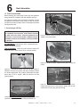
6
Gas Information
A. Fuel Conversions
Before making gas connections ensure that the appliance
being installed is compatible with the available gas type.
Any natural or propane gas conversions necessary to meet
the appliance and locality needs must be made by a qualified technician using Hearth & Home Technologies specified
and approved parts.
3 screws
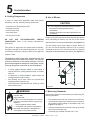
1. Converting to LP Gas
NOTE: Gas conversions should only be performed
by a qualified service person, and/or where required
by state and local codes, licensed installer/service
technician. In the Commonwealth of Massachusetts,
installation must be performed by a licensed plumber
or gas fitter.
Figure 6.3
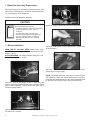
Remove the three screws on the front of the burner
support. Set screws aside.
KIT CONTENTS: Replacement orifice; replacement pilot
injector; and valve regulator.
TOOLS REQUIRED: Power drill (a 90° handle is helpful); #2
Phillips bit; 5/32 in. Allen wrench; 5/8 in. open end wrench.
Opens Left
Closes Right
Figure 6.4
Slide the burner support to the left to access the
orifice.
Figure 6.1
Disconnect power and turn off gas supply if
installed. Remove front, glass, and logs if installed. Loosen
the shutter adjustment nut (located underneath the appliance) with a 7/16 in. wrench. Slide the shutter to the left
(open position).
Figure 6.5
Remove the main burner orifice using a 5/8 in.
wrench and replace the orifice with the proper size as indicated below for your gas type and venting.
Burner Screws
Figure 6.2 Burner removal: Remove burner by first removing the two screws indicated and lifting the burner out.
Quadra-Fire • Topaz • 7009-113 Rev. i • 6/11
23
2. Valve Regulator Replacement
WARNING
Fire Risk.
Explosion Risk.
• Disconnect any electrical cords and
turn off gas supply to unit before
proceeding if converting fuel on an
appliance already fully installed.
Figure 6.6
Pull off pilot hood and set it aside.
NOTE: Do not remove the retaining clip from the hood.
Remove upper and lower back shield. Loosen the set collars on the extension rods with the 3/32 in. Allen wrench.
Remove the rods and adapter cap.
A
Mounting Screws
B
Pressure Regulator Tower
C
Figure 6.7
Diaphragm
Use a 5/32 in. Allen wrench to remove the pilot
injector.
Replace pilot injector with the one supplied with the appliance (#35 for Propane, #62 for Natural Gas).
Replace pilot hood, snapping it into position, making sure
notch and tab line up.
Reinstall burner by placing it into the firebox. Make sure to
reinstall all the screws previously removed.
Reinstall logs, glass and front.
PROPANE
.073 (49 DMS)
24
Figure 6.8
Turn control knob to the OFF position, ensure that
gas supply to the valve has been turned off. Using a Torx
TH20, or slotted screwdriver, remove the three pressure regulator mounting screws (A), pressure regulator tower (B),
and diaphragm (C).
NATURAL GAS
.0125 (1/8 in.)
Quadra-Fire • Topaz • 7009-113 Rev. i • 6/11
B. Gas Pressures
E
Screws
Proper input pressures required for optimum appliance performance, gas line sizing requirements need to be followed
from NFPA51.
D
WARNING
Rubber Gasket
Identification Label
F
Ensure that the rubber gasket (D) is properly positioned and install the new HI/LO pressure regulator assembly to the valve using the new screws (E) supplied with the
kit. Tighten screws securely. (Reference torque = 25 in./lb.)
Install the enclosed identification label (F) to the valve body
where it can be seen.
Figure 6.9
Fill out the conversion label and attach it to the valve cover.
Fire Risk.
Explosion Hazard.
High pressure will damage valve.
• Disconnect gas supply piping BEFORE
pressure testing gas line at test pressures
above 1/2 psig.
• Close the manual shutoff valve BEFORE
pressure testing gas line at test pressures
equal to or less than 1/2 psig.
WARNING
Verify inlet pressures.
• High pressure may cause overfire condition.
• Low pressure may cause explosion.
Install regulator upstream of valve if line pressure
is greater than 1/2 psig.
WARNING
Fire Risk.
Explosion Risk.
Gas Leak Risk.
• Rubber gasket must be seated properly on valve
face.
• Do no install a valve or regulator that has been
dropped.
WARNING
Pressure requirements for appliance are shown in the table
below.
PRESSURE
NG
LP
Minimum Inlet Pressure
5 inches w.c.
11 inches w.c.
Maximum Inlet Pressure
10 inches w.c.
13 inches w.c.
Manifold Pressure on “HI”
3.5 inches w.c.
10 inches w.c.
If the pressure is not sufficient, ensure:
Fire Risk.
Explosion Risk.
• If the information in these instructions is
not followed exactly, a fire, explosion or
production of carbon monoxide may result
causing property damage, personal injury
or loss of life.
• The qualified service agency is responsible
for the proper installation of this conversion
kit. The installation is not proper and
complete until the operation of the converted
appliance is checked as specified in the
manufacturer’s instructions supplied with
the kit.
1) the piping used is large enough.
2) the supply regulator is adequately adjusted.
3) that the total gas load for the residence does not exceed
the amount supplied.
The supply regulator (the regulator that attaches directly to
the residence inlet or to the propane tank) should supply gas
at the suggested input pressure listed above. Contact the
local gas supplier if the regulator is at an improper pressure.
Quadra-Fire • Topaz • 7009-113 Rev. i • 6/11
25
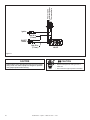
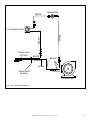
C. Gas Connection
NOTE: Have the gas supply line installed in accordance with
local building codes, if any. If not, follow ANSI Z223.1. Installation should be done by a qualified installer approved and/or
licensed as required by the locality. (In the Commonwealth of
Massachusetts, installation must be performed by a licensed
plumber or gas fitter.)
NOTE: A listed (and Commonwealth of Massachusetts
approved) 1/2 inch (13mm) T-handle manual shut-off valve and
flexible gas connector are connected to the 1/2 inch (13mm)
control valve inlet.
• If substituting for these components, please consult local
codes for compliance.
WARNING
Gas Leak Risk.
• Support control when attaching pipe to
prevent bending gas line.
• A small amount of air will be in the gas supply lines.
When first lighting appliance it will take a short time for
air to purge from lines. When purging is complete the
appliance will light and operate normally.
Air only needs to be purged again if gas valve has been
turned to the OFF position.
WARNING
CHECK FOR GAS LEAKS
Explosion Risk
Fire Risk
Asphyxiation Risk
• Check all fittings and connections.
• Do not use open flame.
• After the gas line installation is complete, all
connections must be tightened and checked
for leaks with a commercially-available,
non-corrosive leak check solution. Be sure
to rinse off all leak check solution following
testing.
Fittings and connections may have loosened
during shipping and handling.
NOTE: The gap between the supply piping and gas access
hole may be plugged with non-combustible insulation to prevent
cold air infiltration.
Leak test all gas line joints and the gas control valve prior
to and after starting the fireplace.
Before making the gas connection, ensure that the appliance
you are installing is designed for the type of gas being
supplied. This information can be found on the Ratings Label
under the appliance. If the appliance has been converted to
propane (LP), the valve cover should have a label stating
that the unit has been converted to propane.
Connect the gas line at the 3/8 in. (9.5mm) pipe connector
on the valve at the back of appliance. We recommend
connecting the appliance with an approved flex gas line.
If flex gas lines are not approved in your area, you must
connect a hard pipe to the gas hookup.
You must supply a manual shut-off valve in a visible location
within 3 feet (914mm) of the appliance.
WARNING
Fire hazard.
Do NOT change the valve settings.
• This valve has been preset at the factory.
• Changing valve settings may result in fire
hazard or bodily injury.
Omni-Test Laboratories listed gas appliances are tested
and approved without requiring changes for elevations from
0 to 2000 feet in the U.S.A. and 0 to 4500 feet in Canada.
When installing this appliance at an elevation above 2000
feet, it may be necessary to decrease the input rating by
changing the existing burner orifice to a smaller size. Input
rate should be reduced by 4% for each 1000 feet above a
2000 foot elevation in the U.S.A. If the heating value of the
gas has been reduced, these rules do not apply. To identify
the proper orifice size, check with the local gas utility.
If installing this appliance at an elevation above 4500 feet
(in Canada), check with local authorities.
WARNING
Fire or Explosion Hazard
• Gas build-up during line purge may ignite.
• Purge should be performed by qualified technician.
• Ensure adequate ventilation.
• Ensure there are no ignition sources such as
sparks or open flame.
26
Quadra-Fire • Topaz • 7009-113 Rev. i • 6/11
7
Electrical Information
A. Recommendation for Wire
See B5 below for recommended maximum lead length (two
wire) when using wall thermostat/switch.
NOTE: This appliance must be electrically wired and
grounded in accordance with local codes or, in the absence
of local codes, with National Electric Code ANSI/NFPA
70-latest edition or the Canadian Electric Code, CSA
C221.1.
8.
Ensure the thermostat is mounted level for accurate
readings.
9.
The thermostat should be mounted on an inside wall
and not in direct line with the appliance convection air.
10. If the thermostat is located too close to the appliance,
you may need to set the temperature setting slightly
higher to maintain the desired temperature in your
home.
Do not connect this appliance to a thermostat serving
any other appliance.
B. Connecting to the Appliance
Bedroom installation in Canada requires this appliance
to be connected to a thermostat.
WARNING
Wire 110v to electrical junction box.
Do NOT wire 110v to the valve.
Do NOT wire 110V to wall switch.
• Incorrect wiring will damage millivolt
systems.
WARNING
Shock hazard.
• This appliance is equipped with a three
pronged (grounding) plug for your protection
against shock hazard and should be plugged
directly into a properly
prop
grounded three prong
receptacle. Do not cut or remove the grounding
prong from this plug.
1.
This appliance may be used with a wall switch, wall
mounted thermostat and / or a remote control.
2.
If using thermostat, use one compatible with a millivolt
gas valve system.
C. Standing Pilot Ignition System Wiring
3.
Follow parameters for locating thermostat (see individual thermostat instructions) to ensure proper operation
of appliance.
This appliance DOES NOT require 110 VAC supply for
operation. A wiring diagram is shown in Figure 7.1 on the
next page.
4.
Use low resistance thermostat wire for wiring from ignition system to the wall switch and thermostat.
This appliance is equipped with a millivolt control valve.
5.
Use the following chart for wire sizing.
Wire Size
Max. Length
16 gauge
65 feet
18 gauge
40 feet
20 gauge
25 feet
22 gauge
18 feet
6.
Keep wire lengths as short as possible by removing
any excess wire length.
7.
Low voltage and 110 VAC voltage cannot be shared
within the same wall box.
Quadra-Fire • Topaz • 7009-113 Rev. i • 6/11
27
Thermopile
Gas Pilot Ignitor
Thermocouple
Ignitor
Red 28 in.
(711mm)
ON/OFF
Switch
Red 28 in.
(711mm)
VALVE
Figure 7.1
CAUTION
CAUTION
Label all wires prior to disconnection when servicing controls.
Wiring errors can cause improper and dangerous operation.
Verify proper operation after servicing.
28
Shock hazard.
• Replace damaged wire with type 105O C
rated wire.
• Wire must have high temperature insulation.
Quadra-Fire • Topaz • 7009-113 Rev. i • 6/11
8
Appliance Setup
A. Remove Shipping Materials
Remove shipping materials from inside or underneath the
firebox.
B. Top to Rear Vent Conversion
KIT CONTENTS: Rear vent grille.
TOOLS REQUIRED: Power drill; #2 Phillips bit;high-temp
silicone sealant (optional.)
Figure 8.3
Remove rear valve cover shield. Remove rear
access plate and gasket. Save the screws.
Figure 8.1
Remove top trivet, if installed. Remove vent pipe
adapter and gasket. If gasket breaks, apply high-temperature
silicone to the bottom of the adapter before installing as indicated in Figure 8.6.
CAUTION
Sharp Edges
Figure 8.4 Place cover plate and gasket over top vent and
attach with the eight screws previously removed.
• Wear protective gloves
and safety glasses during
installation.
Figure 8.5
Figure 8.2
Insert inner collar adapter to rear vent flue.
Remove inner collar adapter
Quadra-Fire • Topaz • 7009-113 Rev. i • 6/11
29
Figure 8.9
Slide assembled nuts and bolts into the slots on
the legs with the nuts on the bottom.
Figure 8.6
Install vent pipe adapter with gasket or high-temp
silicone to rear vent opening.
Figure 8.10
Use a 5/32 in. 4mm) Allen wrench to adjust legs
up and down to desired level.
D. Accessories
Figure 8.7
Place grille gently into the opening on top of the
appliance.
Install approved accessories per instructions included with
accessories. Refer to Section 12 for appropriate accessories.
WARNING
C. Leg Leveling System
Shock or fire risk.
Use ONLY optional accessories approved for
this appliance.
• Using non-listed accessories voids warranty.
• Using non-listed accessories may result in a
safety hazard.
• Only Hearth & Home Technologies approved
accessories may be used safely.
Figure 8.8 Thread Allen bolts through nuts until flush. The
Allen bolts and nuts are included in the component pack inside
the appliance firebox.
30
Quadra-Fire • Topaz • 7009-113 Rev. i • 6/11
E. Front Installation
Fronts shipped attached to face
INSTALLATION AND REMOVAL INSTRUCTIONS
FOR QUARTET AND SOLITAIRE FACE OPTIONS.
Quartet Front
Figure 8.13 Lift up on the top of the Front, gently pulling out
on the bottom. Set aside in a safe location.
Solitaire Front
Spacer
Figure 8.14
The quartet door requires the use of a spacer for
installation. The spacer is shipped in place and should be
put back if removed.
Figure 8.11
For BOTH Quartet and Solitaire Fronts:
F. Brick Installation
NOTE: The brick supplied with the Topaz is not an
optional accessory. The brick must be installed for safe
and proper operation.
Figure 8.12
To remove the face, loosen the thumb bolt beneath
the ashlip.
Figure 8.15
Install rear panel by placing it behind the log pins,
flush and centered against the back of the firebox.
NOTE: Rear panel and top panel/baffle are the same size.
Quadra-Fire • Topaz • 7009-113 Rev. i • 6/11
31
Figure 8.18
Fully installed brick set. Note that with the brick
installed the firebox is narrower at the back than in the front.
G. Positioning the Logs
While still breakable, the logs do not become fragile until
after the appliance is burned and they have cured. After
curing, any handling must be done with care as breakage
can easily occur.
Figure 8.16
Install left or right side panel. Place in lower channel and rotate into place.
NOTE: Side brick panels will fit only if installed at an angle.
Do not attempt to push the brick flat against the outer wall
of the firebox. Brick should rest against spacer on inside of
firebox.
PLEASE NOTE: Logs have been designed to work
specifically with the burner of this appliance. Exact
placement will ensure proper operation of your gas
appliance and reduce sooting.
1
4
5
2
3
Figure 8.19
Figure 8.17
Bend over tabs to hold panel in place.
Install the top panel/baffle. If rear venting, set damper prior
to installing the top panel/baffle. (In the Commonwealth of
Massachusetts, the word damper shall be replaced with the
word damper shall be replaced with the words flue restrictor.)
The back edge will slide in front of the rear brick panel. Rest
one end of the top panel/baffle on the installed side panel
and support the other end with one hand.
The log set is packed in the components box and
consists of the following:
Qty.
#
Rear Log
1
1
Left Front Log
2
1
Right Front Log
3
1
Left Twig
4
1
Right Twig
5
Install the remaining side panel and bend over the tabs to
hold it in place. Rest top panel/baffle on sides and slide top
panel/baffle left or right until centered.
32
Description
1
Quadra-Fire • Topaz • 7009-113 Rev. i • 6/11
Locater Pins
Figure 8.20 Insert locator pin into right front log. Insert rear
log onto log pan over stud.
Figure 8.24
Place left twig over locator pins on the rear log
and the left front log. To complete your log set applica-
tion reinstall the glass and the front of the unit.
H. Mineral Wool
WARNING
Explosion Risk.
• Follow ember placement instructions in
manual.
• Do NOT place embers directly over
burner ports.
• Replace ember material annually.
Figure 8.21
Insert locator pin into left front log. Place left front
log on burner in the grooved provided on the burner surface.
Improperly placed embers interferes with proper burner
operation.
Figure 8.22
Insert locator pin into right front log. Place right
front log on burner in the grooves provided on the burner
surface.
Figure 8.25
Place individual pieces of embers in front of and
around the gas log where they can be seen. Space them so
that gas can contact them on all sides. Avoid stacking the
embers on top of each other.
NOTE: Do not block gas ports.
Figure 8.23
Place right twig over the locator pins on the rear
log and the right front log.
Quadra-Fire • Topaz • 7009-113 Rev. i • 6/11
33
I. Glass Door Assembly Replacement
Remove the glass door assembly by opening latches at the
bottom front of the appliance, on both the left and right sides.
Lift out and away from the appliance.
Replace with a new glass door assembly.
CAUTION
Handle glass assembly with care.
Figure 8.28
Connect electrical connector to snap disc.
• Inspect the gasket to ensure it is undamaged.
• Inspect the glass for cracks, chips or
scratches.
• Do NOT strike, slam or scratch glass.
• Do NOT operate appliance with glass door
removed, cracked, broken or scratched.
• Replace glass assembly as a complete
assembly.
J. Blower Installation
Figure 8.29
FROM THE KIT YOU WILL NEED: Blower motor; snap
disc bracket with wire harness; rheostat, rheostat nut; knob;
screws; 1 zip-tie.
Install speed control to switch panel. Attach knob
to speed control.
TOOLS REQUIRED: #2 Phillips head bit; hand drill; 11/16
in. wrench; and a 5/16 in. wrench.
Figure 8.30
Reinstall rear shield. Connect blower to power
supply and turn on gas supply.
Attach with 4
screws
Figure 8.26 Turn off gas supply, (if gas is connected,) and
remove rear shield. Remove blower from packaging. Place
blower under appliance. Attach blower from front with 4
screws to blower bracket.
NOTE: This blower utilizes a snap disc to control ON and
OFF operation. When the correct temperature is reached,
the blower will automatically turn ON. Use the rheostat knob
to adjust the fan to High or Low to suit your preferences.
5/16" nut
Snap Disc
Bracket
Figure 8.27 Install snap disc in bracket. Attach bracket to firebox with 5/16 in. wrench.
34
Quadra-Fire • Topaz • 7009-113 Rev. i • 6/11
Thermal Disc
WHITE
BLACK
WHITE
Fan Speed Control
BLACK
GREEN
Ground
Strain Relief
Bushing
BLACK
WHITE
Power Cord
(110 VAC)
BLACK
Fan Assembly
Figure 8.31 Blower Wiring Diagram
Quadra-Fire • Topaz • 7009-113 Rev. i • 6/11
35
K. Damper Adjustment
L. Shutter Adjustment
FOR TOP OR REAR VENT INSTALLATIONS
OPEN
See Vent Graph for Recommendations on page 11
before you begin your adjustment. If your installation falls
within the range of the gray shaded area of graph, it may be
necessary to make an adjustment to the vertical damper to
improve the flame appearance in your appliance.
CLOSE
Figure 8.34
The shutter is located on the underside of the
appliance, on the right side. To adjust the shutter, loosen
the wingnut..
TOP VENT INSTALLATIONS:
Locate the damper adjustment on the intake plenum. Access
through the appliance front. Adjustor is centered at the top
of the appliance.
Figure 8.32
Make adjustment:
Moving the shutter bolt to the right closes the shutter. Moving
the shutter bolt to the left, will open the shutter. Opening the
shutter causes flames to become shorter and blue. Closing
the shutter creates taller orange/yellow flames.
NOTE: Do not close so much as to cause a sooty flame.
Improper adjustment can cause sooting in the firebox and/
or on the outside of a house with a horizontal termination.
Let appliance warm up before adjusting.
Loosen screw using a Phillips head screwdriver.
After adjustment, tighten wingnut to lock in place.
Pivot the vertical damper adjustor in 1/4 in. (6mm) increments while observing the flame activity.
Turning clockwise to open damper = less flame height and
more blue in flame color.
Turning counterclockwise to close damper = increased flame
height and more yellow in flame color.
Make adjustment until flame size and activity suits your personal preference, and then retighten screws on adjustment
control.
Figure 8.33 REAR VENT INSTALLATIONS: The rear vent
damper is located in the back of the firebox behind the rear
brick panel. It is recommended to make adjustment prior to
installation.
Remove front/glass/ logs and brick if installed. Loosen
screws and slide up to suggested settings. Reinstall
accordingly... Tighten screws.
36
Quadra-Fire • Topaz • 7009-113 Rev. i • 6/11
9
Operating Instructions
A. Before Lighting Appliance
Read this entire manual prior to using the appliance. Failure
to follow the instructions may result in property damage,
bodily injury, or even death.
•
Remove all shipping materials from inside and/or
underneath the firebox.
•
Review proper placement of logs, mineral wool.
•
Check the wiring.
•
Check the baffle adjustment.
•
Ensure that there are no gas leaks.
•
Ensure that the glass is sealed and in the proper position.
•
Ensure that the flow of combustion and ventilation air
is not obstructed (front grilles and vent caps).
WARNING
Improper installation, adjustment, alteration, service or
maintenance can cause injury or property damage. Refer to
the owner’s information manual provided with this appliance.
For assistance or additional information consult a qualified
installer, service agency or the gas supplier.
WARNING
Do NOT use this appliance if any part has been under water.
Immediately call a qualified service technician to inspect the
appliance and to replace any part of the control system and
any gas control which has been under water.
B. Controls
WARNING
Glass door must be in place when appliance is
operating.
MAIN BURNER: This control is used to turn the appliance
on and off.
Risk of:
• Combustion Fumes
• Fire
•
•
•
•
FAN SPEED: This knob controls the speed of the blower
that pushes the heated air into the room.
Do NOT operate appliance with glass door
removed.
Open viewing glass for servicing only.
Glass door MUST be in place and sealed before
operating appliance.
Only use glass door certified for use with appliance.
Glass replacement should be done by qualified
technician.
WARNING
HOT! DO NOT TOUCH.
SEVERE BURNS MAY RESULT.
CLOTHING IGNITION MAY RESULT.
Glass and other surfaces are hot
during operation and cool down.
PILOT IGNITOR: The pilot ignitor is used only to start
the pilot. When the valve control knob is turned to the
pilot position and fully depressed press the piezo ignitor
repeatedly creating a blue spark directly next to the pilot,
igniting the pilot flame.
VALVE CONTROL: This knob is used to control gas to
the appliance and for starting the pilot. There are three
positions, ON, OFF, & PILOT. The indicator on the valve
indicates the position of the knob.
COMFORT CONTROL: This knob controls the flame height
from low (“LO”) to high (“HI”).
NOTE: If using a remote control wall switch, or thermostat,
the On/Off Switch must be left “OFF”. Turning the On/Off
Switch to “ON” will keep the appliance on continually.
• Keep children away.
• CAREFULLY SUPERVISE children in same room as
appliance.
• Alert children and adults to hazards of high temperatures.
• Do NOT operate with protective barriers open or removed.
• Keep clothing, furniture, draperies and other combustibles
away.
Quadra-Fire • Topaz • 7009-113 Rev. i • 6/11
37
C. Lighting Appliance
FOR YOUR SAFETY READ BEFORE LIGHTING
WARNING: If you do not follow these instructions exactly, a fire or explosion may
result causing property damage, personal injury or loss of life
A. This appliance has a pilot that must be lit manually. When lighting the pilot, follow these instructions exactly.
B. BEFORE LIGHTING, smell around the appliance area for gas. Be sure to smell next to the floor because some gas is heavier
than air and will settle on the floor.
WHAT TO DO IF YOU SMELL GAS:
* Do not try to light any appliance.
* Do not touch any electric switch, do not use any phone in your building.
* Immediately call your gas supplier from a neighbor's phone. Follow the gas supplier's instructions.
* If you cannot reach your gas supplier, call the fire department.
C. Use only your hand to push in or turn the gas control knob. Never use tools. If the knob will not push in or turn by hand, don't
try to repair it, call a qualified service technician. Force or attempted repair may result in a fire or explosion.
D. Do not use this appliance if any part has been under water. Immediately call a qualified service technician to inspect the appliance
and to replace any part of the control system and any gas control which has been under water.
LIGHTING INSTRUCTIONS
1. STOP! Read the safety information above on this label.
2. Set the thermostat to the lowest setting (if applicable) and turn off
the switch at the control panel.
3. Disconnect the power from the appliance.
4. Open the door of the appliance. May need to remove face/front first.
5. Push in gas control knob slightly and turn clockwise
to the "OFF"
position. Do not force.
6. Wait five (5) minutes to clear out any gas. Smell for gas, including near the floor. If you smell gas, STOP! Follow "B" of the
safety information above. If you don't smell gas go to the next step.
7. Push gas control knob in and turn counterclockwise
to the pilot position. NOTE: Knob cannot be turned unless knob is
pushed in slightly. Do not force.
8. PIEZO IGNITER: Press down on the gas control knob in pilot position and simultaneously press the piezo igniter.
(This may take many repetitions for lighting.)
ELECTRONIC IGNITER: If the unit is equipped with an electronic igniter it should begin sparking right away.
9. The pilot should be visible through the door opening.
10. After the pilot is lit, continue holding control knob down for approximately
PILOT HOOD
30 seconds. Release the knob and it will pop back up. Pilot should remain lit. MILLIVOLT
THERMOCOUPLE
GENERATOR
If it goes out, repeat steps 7 through 9.
* If the knob does not pop up when released, stop and immediately call your
service technician or gas supplier.
* If the pilot will not stay lit after several tries, turn the gas control knob
clockwise
to "OFF" and call your service technician or gas supplier.
11. Re-install door and face. Wait five minutes to allow pilot flame to stabilize and
establish proper draft.
12. Push down and turn gas control knob counterclockwise
to "ON".
13. Push burner rocker switch on the control panel to "ON". If thermostat is to be used, leave switch in "OFF" position and set the
thermostat to desired setting.
14. Reconnect electrical power to appliance.
TO TURN OFF GAS TO APPLIANCE
1. Set the thermostat to lowest setting.
2. Turn off all electric power to the appliance if service is to be performed.
3. Push in gas control knob slightly and turn clockwise
to "OFF" position.
38
Quadra-Fire • Topaz • 7009-113 Rev. i • 6/11
D. After Appliance is Lit
CAUTION
Initial Break-in Procedure
When you light your appliance, you may notice that it produces heat which does have an associated odor or smell. If
you feel this odor is excessive it may require the initial three
to four hour continuous burn on high followed by a second
burn up to 12 hours to fully drive off any odor from paint and
lubricants used in the manufacturing process. Condensation
on the glass is normal.
NOTE: The appliance should be run three to four hours
on the initial start-up. Turn it off and let it cool completely.
Remove and clean the glass. Replace the glass and run the
appliance for an additional 12 hours. This will help to cure
the products used in the paint and logs.
During this break-in period it is recommended that some
windows in the house be opened for air circulation. This will
help avoid setting off smoke detectors, and help eliminate
any odors associated with the appliance’s initial burning.
WARNING
Fire Risk.
High Temperatures.
• Prevent accidental appliance operation when not
attended.
• Unplug or remove batteries from remote control if absent
or if appliance will not be used for an extended period of
time.
• Property damage possible from elevated temperatures.
CAUTION
Smoke and odors released during initial operation.
• Open windows for air circulation.
• Leave room during initial operation.
• Smoke may set off smoke detectors.
Smoke and odors may be irritating to sensitive individuals.
WARNING
Fire Hazard.
Keep combustible materials, gasoline
and other flammable vapors and liquids
clear of appliance.
• Do NOT store flammable materials in the appliance’s
vicinity.
• Do NOT use gasoline, lantern fuel, kerosene, charcoal
lighter fluid or similar liquids in this appliance.
• Combustible materials may ignite.
Keep combustible household items away from appliance.
Do NOT obstruct combustion and ventilation air.
• Do NOT place combustible items on top of or in front of
appliance.
• Keep furniture, draperies away from appliance.
E. Frequently Asked Questions
ISSUE
SOLUTIONS
Condensation on the glass
This is a result of gas combustion and temperature variations. As the appliance warms,
this condensation will disappear.
Blue flames
This is a result of normal operation and the flames will begin to yellow as the appliance
is allowed to burn for 20 to 40 minutes.
Odor from appliance
When first operated, this appliance may release an odor for the first several hours.
This is caused by the curing of the paint and the burning off of any oils remaining from
manufacturing. If appliance has not been used for some time, dust can build up and
cause an odor.
Film on the glass
This is a normal result of the curing process of the paint and logs. Glass should be
cleaned within 3 to 4 hours of initial burning to remove deposits left by oils from the
manufacturing process. A non-abrasive cleaner such as gas appliance cleaner may be
necessary. See your dealer.
Metallic noise
Noise is caused by metal expanding and contracting as it heats up and cools down,
similar to the sound produced by a furnace or heating duct. This noise does not affect
the operation or longevity of the appliance.
Quadra-Fire • Topaz • 7009-113 Rev. i • 6/11
39
10
Troubleshooting
With proper installation, operation, and maintenance your gas appliance will provide years of trouble-free service. If you do
experience a problem, this troubleshooting guide will assist a qualified service person in the diagnosis of a problem and the
corrective action to be taken. This troubleshooting guide can only be used by a qualified service technician.
Symptom
1. After repeated triggering of the piezo
button, the spark ignitor
will not light the pilot.
2. The pilot will not stay
lit after carefully following the lighting instructions.
Possible Cause
Corrective Action
a. Defective ignitor.
Check the spark at the electrode and pilot. If no spark and electrode
wire is properly connected, replace the ignitor.
b. Defective pilot or
misaligned electrode
(spark at electrode).
Using a match, light the pilot. If the pilot lights, turn off the pilot and
trigger the piezo button again. If the pilot lights, an improper gas/air
mixture caused the bad lighting and a longer purge period is recommended. If the pilot will not light, ensure the gap at the electrode and
pilot is one-eighth (1/8) inch to have a strong spark. If the gas is OK,
replace the pilot.
c. No gas or low gas
pressure.
Check the remote shut-off valve from the appliance. Usually, there is
a valve near the gas main. There can be more that one (1) valve from
the appliance and the main.
d. No LP in tank.
Check the LP (propane) tank. You may be out of fuel.
a. Defective thermocouple.
Check that the pilot flame impinges on the thermocouple. Clean and /
or adjust the pilot for maximum flame impingement.
Ensure that the thermocouple connection at the gas valve is fully
inserted and tight (hand tighten plus 1/4 turn).
Disconnect the thermocouple from the valve, place one millivolt lead
wire on the tip of the thermocouple and the other meter wire on the
thermocouple copper lead. Start the pilot and hold the valve knob in. If
the millivolt reading is less than 15mV, replace the thermocouple.
b. Defective valve.
3. The pilot is burning,
a. ON/OFF switch or
there is no gas to the
wires defective.
burner, the valve knob is
in the ON position, and
the ON/OFF switch is in
the ON position.
b. Thermopile may
not be generating
sufficient millivoltage.
If the thermocouple is producing more than 15 millivolts, replace faulty
valve.
Check the ON/OFF switch and wires for proper connections. Place the
jumper wires across the terminals at the switch. If the burner comes on,
replace the defective switch. If the switch is OK, place the jumper wires
across the switch wires at the gas valve. IF the burner comes on, the
wires are faulty or connections are bad.
If the pilot flame is not close enough physically to the thermopile, adjust
the pilot flame.
Be sure the wire connections from the thermopile at the gas valve terminals are tight and that the thermopile is fully inserted into the pilot
bracket.
Check the thermopile with a millivolt meter. Take the reading at THTP&TP terminals of the gas valve. The meter should read 325 millivolts
minimum, while holding the valve knob depressed in the pilot position,
with the pilot lit, and the ON/OFF switch in the OFF position. Replace
the faulty thermopile if the reading is below the specified minimum.
With the pilot in the ON position, disconnect the thermopile leads from
the valve. Take a reading at the thermopile leads. The reading should
be 325 millivolts minimum. Replace the thermopile if the reading is
below the minimum.
40
Quadra-Fire • Topaz • 7009-113 Rev. i • 6/11
Symptom
3. (Continued)
Possible Cause
Corrective Action
c. Defective valve.
Turn the valve knob to the ON position. Place the ON/OFF switch in
the ON position. Check the millivolt meter at the thermopile terminals.
The millivolt meter should read greater than 125mV. If the reading is
acceptable, and if the burner does not come on, replace the gas valve.
d. Plugged burner
orifice.
Check the burner orifice for stoppage. Remove stoppage.
e. Wall switch or
wires are defective.
Follow the corrective action in Symptom and Possible Cause 1.a.
Check the switch and wiring. Replace where defective.
4. Frequent pilot outage a. Pilot flame may
Clean and adjust the pilot flame for maximum flame impingement on
problem.
be too high or too
thermocouple. Follow lighting instructions carefully.
low, or blowing
(high), causing safety
pilot to drop out.
5. The pilot and main
burner extinguish while
in operation.
a. No LP in tank.
Check the LP (propane) tank. Refill the fuel tank.
b. Inner vent pipe
leaking exhaust
gases back into the
system.
Check for proper vent connection at flue collar and all vent joints.
c. Horizontal vent
improperly pitched.
The horizontal vent cap should slope down only enough to prevent any
water from entering the appliance.
d. Bad thermopile or
thermocouple.
Replace if necessary.
e. Improper vent cap Check for proper installation and freedom from debris or blockage.
installation.
6. Glass soots.
7. Flame burns blue
and lifts off burner.
a. Flame impingement.
Adjust the log set so that the flame does not excessively impinge on it.
Check that logs are placed according to installation instructions.
b. Improper shutter
setting.
Adjust the air shutter at the base of the burner.
c. Debris around
opening at base of
burner.
Inspect the opening at the base of the burner. NO MATERIAL SHOULD
BE PLACED IN THIS OPENING.
a. Insufficient
oxygen being supplied.
Ensure that the vent cap is installed properly and free of debris. Ensure
that the vent system joints are tight and have no leaks.
Ensure that no debris has been placed at the base of, or in the area of
the air holes in the center of the base pan beneath the burner.
Ensure that the glass is tightened properly on the appliance, particularly on top corners.
Quadra-Fire • Topaz • 7009-113 Rev. i • 6/11
41
11
Maintaining and Servicing Your Appliance
Although the frequency of your appliance servicing and
maintenance will depend on use and the type of installation,
a qualified service technician should perform an appliance
check-up at the beginning of each heating season.
CAUTION
Handle glass assembly with care.
NOTE: Clean glass after initial 3-4 hours
operation. Longer operation without cleaning
glass may cause a permanent white film on
glass.
WARNING
Risk of injury or property damage.
Before servicing:
• Turn off gas.
• Turn off electricity to appliance.
• Ensure appliance is completely cooled.
After servicing:
• Replace front and glass, if removed.
• Reseal and reinstall any venting removed for servicing.
WARNING
When cleaning glass door:
• Avoid striking, scratching or slamming glass.
• Do NOT use abrasive cleaners.
• Use a hard water deposit glass cleaner on white film.
• Do NOT clean glass when hot.
• Turn off appliance after 3-4 hours of operation and ALLOW
TO COOL.
• Remove and clean glass assembly.
• Replace glass assembly and operate appliance for additional
12 hours.
Refer to maintenance instructions.
Annual inspection by qualified technician recommended.
Check:
• Condition of glass, glass assembly and glass seal.
• Obstructions of combustion and ventilation air.
• Obstructions of termination cap.
• Burner ignition and operation.
• Burner air shutter adjustment
• Gas connections and fittings.
Clean:
• Glass
• Air passageways, grilles,
control compartment
• Burner, burner ports. USE CAUTION WHEN CLEANING/
HANDLING CERAMIC BURNER.
Risk of:
• Fire
• Delayed ignition or explosion
• Exposure to combustion fumes
• Odors
WARNING
Inspect external vent cap regularly.
• Ensure no debris blocks cap.
• Combustible materials blocking cap may
ignite.
• Restricted air flow affects burner operation.
42
Quadra-Fire • Topaz • 7009-113 Rev. i • 6/11
A. Maintenance Tasks
Inspect
Doors
Maintenance Tasks
1. Inspect for scratches, dents or other damage and repair as necessary.
2. Verify no obstructions to air flow.
3. Verify maintenance of proper clearance to combustible household objects.
Gasket Seal, Glass
Assembly and Glass
1. Inspect gasket seal and its condition.
2. Inspect glass for scratches and nicks that can lead to breakage when exposed to heat.
3. Confirm there is no damage to glass or glass frame, Replace as necessary.
4. Verify that latches engage properly and glass attachment components are intact and operating properly. Replace as necessary.
5. Clean glass. Replace glass assembly if severely coated with silicate deposits that cannot
be removed.
Valve Compartment
and Firebox Top
1. Vacuum and wipe out dust, cobwebs, debris or pet hair. Use caution when cleaning these
areas. Screw tips that have penetrated the sheet metal are sharp and should be avoided.
2. Remove any foreign objects.
3. Verify unobstructed air circulation.
Logs
1. Inspect for broken, damaged, or missing logs. Replace as necessary.
2. Verify correct log placement and no flame impingement causing sooting. Correct as necessary.
Firebox
1. Inspect for paint condition, warpage, corrosion or perforation. Sand and repaint as necessary.
2. Replace appliance if firebox has been perforated.
Burner Ignition and
Operation
1. Verify burner is properly secured and aligned with pilot or igniter.
2. Clean off burner top, inspect for plugged ports, corrosion or deterioration. Replace burner if
necessary. USE CAUTION WHEN CLEANING/HANDLING CERAMIC BURNER.
3. Replace ember material with new dime-size and shape pieces. Do not block ports or obstruct
lighting paths.
4. Check for smooth lighting and ignition carryover to all ports. Verify there is no ignition delay.
5. Inspect for lifting and other flame problems.
6. Inspect orifice for soot, dirt or corrosion.
7. Verify manifold and inlet pressures. Adjust regulator as required.
8. Inspect pilot flame strength. Clean or replace orifice as necessary.
9. Inspect thermocouple/thermopile sensor rod for soot, corrosion and deterioration. Clean with
emery cloth or replace as required.
10. Verify millivolt output. Replace as necessary.
Venting
1. Inspect venting for blockage or obstruction such as bird nests, leaves, etc.
2. Confirm that termination cap remains clear and unobstructed by plants, etc.
3. Verify that termination cap clearance to subsequent construction (building additions, decks,
fences or sheds) has been maintained.
4. Inspect for corrosion or separation.
5. Verify weather stripping, sealing and flashing remains intact.
Remote Controls
1. Verify operation of remote.
2. Replace batteries in remote transmitters and battery-powered receivers.
Quadra-Fire • Topaz • 7009-113 Rev. i • 6/11
43
12
Reference Materials
A. Appliance Dimension Diagram
Dimensions are actual appliance dimensions. Use for reference only. For clearances refer to Section 3.
A
D
E
G
J
I
H
B
C
L
K
M
O
N
Figure 12.1
44
Location
Inches
Millimeter
Location
Inches
Millimeter
A
27-3/8
695
I
19-3/8
492
B
7
178
J
16-7/8
429
C
27-3/4
705
K
22-1/2
572
D
27-1/2
698
L
3-1/8
79
E
13-3/4
349
M
29-1/2
749
F
8-3/8
213
N
18
457
G
5-1/8
130
O
23-1/8
687
H
22-5/8
575
Appliance Dimensions
Quadra-Fire • Topaz • 7009-113 Rev. i • 6/11
F
B. Vent Components Diagram
6-3/8 in.
(162mm)
6-1/2 in.
(165mm)
9-1/4 in.
(235mm)
6-1/2 in.
(165mm)
6-3/8 in.
(162mm)
6-5/8 in.
(168mm)
9-5/8 in.
(244mm)
SLP45-BK
6-5/8 in.
(168mm)
9-5/8 in.
(244mm)
SLP90M
17-24 in.
(432-610mm)
6-1/2 in.
(165mm)
11-3/4 in.
(298mm)
SLP12AM
5-3/4 in.
(146mm)
6-5/8 in.
(168mm)
SLP12M
SLP6M
47-3/4 in.
(1213mm)
35-3/4 in.
(908mm)
23-3/4 in.
(603mm)
12-17 in.
(305-432mm)
3-3/4 in.
(95mm)
SLP4M
SLP6AM
SLP24M
SLP36M
SLP48M
4 in. (102 mm) inner pipe 6-5/8 in. (168 mm) outer pipe
Figure 12.2
SL-D Series Vent Components
Quadra-Fire • Topaz • 7009-113 Rev. i • 6/11
45
C. Vent Components List
Description
HHT SLP
M= Multi Pack (6)
Simpson
Dura-Vent ®
DirectVent Pro
SLP4M
-
SLP4-BK
-
SLP6M
46-DVA-06
SLP6-BK
46-DVA-06B
9” Pipe Length, Galvanized
-
46-DVA-09
9” Pipe Length, Black
-
46-DVA-09B
SLP12M
46-DVA-12
SLP12-BK
46-DVA-12B
18” Pipe Length, Galvanized
-
46-DVA-18
18” Pipe Length, Black
-
46-DVA-18B
SLP24M
46-DVA-24
SLP24-BK
46-DVA-24B
SLP36M
46-DVA-36
SLP36-BK
46-DVA-36B
SLP48M
46-DVA-48
48” Pipe Length, Black
SLP48-BK
46-DVA-48B
Adjustable Length, 3”-6”, Black
SLP6A-BK
-
Adjustable Length, 3”-6”, Galvanized
SLP6AM
-
Adjustable Length, 3”-7”, Galvanized
-
46DVA-08A
Adjustable Length, 3”-7”, Black
-
46DVA-08AB
SLP12A-BK
-
SLP12AM
-
Adjustable Length, 3”-14.5”, Galvanized
-
46DVA-16A
Adjustable Length, 3”-14.5”, Black
-
46DVA-16AB
Adjustable Length, 16”, Galvanized
-
46DVA-16A
Adjustable Length, 16”, Black
-
46DVA-16AB
2’ Flexible Pipe Length
SLP-FLEX-2
-
3’ Flexible Pipe Length
SLP-FLEX-3
-
5’ Flexible Pipe Length
SLP-FLEX-5
-
10’ Flexible Pipe Length
SLP-FLEX-10
-
3” x 35’ Flex Extension
-
2280
4” x 35’ Flex Extension
-
2281
45° Elbow, Galvanized
SLP45M
-
SLP45-BK
See Swivel
45° Elbow, Swivel, Galvanized
-
46DVA-E45
45° Elbow, Swivel, Black
-
46DVA-E45B
4” Pipe Length, Galvanized
4” Pipe Length, Black
6” Pipe Length, Galvanized
6” Pipe Length, Black
12” Pipe Length, Galvanized
12” Pipe Length, Black
24” Pipe Length, Galvanized
24” Pipe Length, Black
36” Pipe Length, Galvanized
36” Pipe Length, Black
48” Pipe Length, Galvanized
Adjustable Length, 3”-12”, Black
Adjustable Length, 3”-12”, Galvanized
45° Elbow, Black
46
Quadra-Fire • Topaz • 7009-113 Rev. i • 6/11
C. Vent Components List (continued)
HHT SLP
M= Multi Pack (6)
Simpson
Dura-Vent ®
DirectVent Pro
SLP90M
See Swivel
SLP90-BK
See Swivel
90° Elbow, Swivel, Galvanized
-
46DVA-E90
90° Elbow, Swivel, Black
-
46DVA-E90B
Adjustable Flashing, 0/12-6/12
SLP-RF6M
46DVA-F6
Adjustable Flashing, 7/12-12/12
SLP-RF12M
46DVA-F12
Attic Insulation Shield 12”
SLP-AS2M
-
-
46-DVA-IS
SLP-CCS-BK
46DVA-CS
Ceiling Support
-
46DVA-DC
Co-Axial to Co-Lineal Appliance Connector
-
46DVA-GCL
Decorative Ceiling Firestop - Black
SLP-DCF-BK
-
Decorative Radius Cover
DRC-RADIUS
-
SLP-FSM
46DVA-FS
SLP-FLEX-TRAP
-
SLP-FLEX-TRAP30
-
Masonry Chimney Conversion Kit
-
46DVA-KMC
Offset Support
-
46DVA-ES
SLP-WT-BK
-
SLP-SCM
46DVA-SC
Wall Support Band
SLP-HVSM
46-DVA-WS
Wall Thimble, Black
SLP-WSM
46DVA-WT
SLP-SK-BK
46DVA-KHA
-
46DVA-GK
SLP-HHW2
46DVA-HC
-
46DVA-KHC
Snorkel Termination 14”
SLK-SNKD
46DVA-SNK14
Snorkel Termination 36”
-
46DVA-SNK36
*Stove Adaptor Kit (Vertical Cap Kit)
LINK-STOVE
-
Trapezoid Termination Kit
(3-1/8”-4-3/4”)
SLP-TRAP1
-
Trapezoid Termination Kit
(5-1/4” X 9-1/4”)
SLP-TRAP2
Description
90° Elbow, Galvanized
90° Elbow, Black
Attic Insulation Shield, Adjustable 11”-20”
Cathedral Support Box
Firestop Spacer/Ceiling Firestop
Flex Trap Cap with Firestop
Flex Trap Cap with Firestop and 30” Flex Pipe
Offset Wall Thimble, Black
Storm Collar
TERMINATION CAPS & KITS
Basic Horizontal Termination Kit (A)
Chimney Liner Termination Kit
Horizontal Square Termination Cap
Horizontal Termination Kit (B)
Vertical Termination Cap
SLP-TVHW
46DVA-VCH
This is not a complete list - contact individual manufacturer for a complete and detailed list
NOTES: 1Before cutting any holes check pipe manufacturers current instructions.
2
Each pipe manufacturer has their own list of parts for kits.
3
SL is not interchangeable with SLP.
* Stove Adaptor Kit (Vertical Cap Kit) Includes 30’-4” Àex, adapters, wall thimble, masonry, ZC Àashing, 991DA vertical cap.
Quadra-Fire • Topaz • 7009-113 Rev. i • 6/11
47
R
TOPAZ
D. Service Parts List
Direct Vent Gas Stove
Color
SKU No.
Mfg. Dates
Quartet Matte Black
839-1290
3/02-Active
Quartet Porcelain Creme
839-1300
5/02-7/05
Quartet Porcelain Green
839-1310
5/02-9/04
Quartet Porcelian Mohagany
839-1320
2/02-Active
Quartet Porcelain Blue
839-1330
5/02/3/03
Quartet Porcelain Midnight Blue
839-1331
5/03-6/05
Quartet Powder Coat Creme
Topaz-D-CCR
9/05-5/06
Quartet Powder Coat Linden Green
Topaz-D-CLG
6/04-5/06
Quartet Powder Coat Sienna Bronze
Topaz-D-CSB
3/07-Active
Quartet Powder Coat Willow
Toapz-D-CWL
3/07-3/11
Color
SKU No.
Solitaire Matte Black
Solitiare Porcelian Creme
Solitiare Porcelian Green
Solitaire Porcelian Mahogany
Solitarie Porcelian Midnight Blue
Solitarie Porcelain Midnight Blue
Mfg. Dates
839-1340
839-1350
839-1360
839-1370
839-1381
839-1381
4/02-Active
5/02-5/04
5/02-9/04
5/02-7/04
7/02-4/03
7/03-5/04
Log Set Assembly
5
4
2
6
3
28
29
1
8
27
7
26
25
24
22
9
10
21
11
12
20
17
13
16
15
14
Part number list on following page.
48
Quadra-Fire • Topaz • 7009-113 Rev. i • 6/11
18
19
23
TOPAZ
D. Service Parts List
IMPORTANT: THIS IS DATED INFORMATION. When requesting service or replacement
parts for your appliance please provide model number and serial number. All parts listed
in this manual may be ordered from an authorized dealer.
ITEM
DESCRIPTION
COMMENTS
Log Set, Topaz
Stocked
at Depot
PART NUMBER
LOGS-TOPAZ
1
Log Front Right Topaz
7009-126
2
Log Front Left Topaz
7009-127
3
Log Top Right Topaz
7009-128
4
Log Top Left Topaz
7009-129
5
Log Rear Topaz
7009-130
Log Pin Ceramic Pkgs of 12
6
7
8
Grill, Rear Vent
Grill Top Vent
Top
1/4” x 1”
7000-465/12
Y
1/4” x 1-1/2”
7000-466/12
Y
Black
844-9830
Mahogany
844-9860
Sienna Bronze
RV-TPZ-CSB
No longer available
RV-TPZ-CWL
Black
468-0040MBK
Mahogany
468-0040PMH
Sienna Bronze
468-0040CSB
Willow
468-0040CWL
Black
468-0010MBK
Mahogany
468-0010PMH
Sienna Bronze
468-0010CSB
Willow
468-0010CWL
9
Cast Mounting Bracket, Bottom
7009-102
10
Door Retainer Assembly
7009-008
11
Retainer, Brick
479-0190
12
Refractory Assembly
BRICK-TOPAZ
13
Face Assembly, Quartet
Ashlip
Door Assembly Left
Black
466-5000MBK
Mahogany
466-5000PMH
Sienna Bronze
466-5000CSB
Willow
466-5000CWL
Black
466-0060MBK
Mahogany
466-0060PMH
Sienna Bronze
466-0060CSB
Willow
466-0060CWL
Black
466-5030MBK
Mahogany
466-5030PMH
Sienna Bronze
466-5030CSB
Willow
466-5030CWL
Y
Additional service part numbers appear on following page.
Quadra-Fire • Topaz • 7009-113 Rev. i • 6/11
49
TOPAZ
D. Service Parts List
IMPORTANT: THIS IS DATED INFORMATION. When requesting service or replacement
parts for your appliance please provide model number and serial number. All parts listed
in this manual may be ordered from an authorized dealer.
ITEM
DESCRIPTION
Door Assembly Right, Quartet
Face
COMMENTS
PART NUMBER
Black
466-5020MBK
Mahogany
466-5020PMH
Sienna Bronze
466-5020CSB
Willow
466-5020CWL
Black
466-0010MBK
Mahogany
466-0010PMH
Sienna Bronze
466-0010CSB
Willow
466-0010CWL
Hinge Assembly
454-5030
Hinge Pin
844-5750
Y
Magnet Round
SRV7000-140
Y
Thumbscrew, 1/4-20 X 3/4
844-5070
14
Face Assembly, Solitaire
15
Door Assembly W/Glass
Solitaire Face Black
7009-007MBK
7011-003
Glass Assembly
23.44 W x 14.32 H
7011-015
Y
Glass Gasket - Field Cut to Size
Qty: 10 Ft.
844-3010
Y
Tape, Door Corner - Field Cut to Size
Qty: 10 Ft.
SRV7027-227
Y
Post 7879357
7009-018
Y
Pre 7879356
BRNR-TOPAZ
Y
16
Burner Assembly
17
Pilot Assembly
842-4940
Y
18
Shutter Assembly
468-5060
Y
19
Bulkhead
26457
Y
20
Bulkhead Stop
474-0090
21
Side Kit - Side Replacement
22
Cast Mounting Bracket, Top
23
Valve Bracket
24
Back Shield Lower
SIDE-TPZ-MBK
Must Specify Color
Pkg of 2
SIDE-TPZ-POR
7009-101/2
Y
7009-104
7009-107
LP Valve
842-0230
Y
NG Valve
842-0240
Y
25
Valve Replacement, Sit
26
Back Shield Upper
7009-106
27
Knob, Extension, Valve, Hi-Low
842-4020
28
Knob, Extension, Valve, On-Off
230-1250
29
Switch Bracket
7009-105
Additional service part numbers appear on following page.
50
Stocked
at Depot
Quadra-Fire • Topaz • 7009-113 Rev. i • 6/11
TOPAZ
D. Service Parts List
IMPORTANT: THIS IS DATED INFORMATION. When requesting service or replacement
parts for your appliance please provide model number and serial number. All parts listed
in this manual may be ordered from an authorized dealer.
ITEM
DESCRIPTION
COMMENTS
Stocked
at Depot
PART NUMBER
Air Deflector
7011-139
Blower Bracket
7010-146
Blower Bracket Rear
7009-103
Brass Elbow
17524
Burner Neck Support Assembly
7011-016
Burner Pan Rear Assembly
7011-017
Burner Pan Side Left
7011-128
Burner Pan Side Right
Y
7011-127
Component Pack Assembly (Includes On/Off Valve; Mineral
Wool; Pilot Injector, Lp 35, Conversion Regulator Lp; Lp
Orifice; Conversion Label; Leveling Assembly; Snap Disc
Bracket; Owners Manual; Warranty Card)
Black
7009-003
Mahogany
7009-016
Sienna Bronze
7009-019
Willow
7009-020
Leveling Assembly
7000-000
Mineral Wool, Bag
200-2550
Nut, Keps Lock, 10-32
226-0050/40
Y
On/Off Valve
15697
Y
Black
Paint Touch-Up, 4 Oz
812-0910
Mahogany
855-1450
Sienna Bronze
TOUCHUP-CSB
Willow
TOUCHUP-CWL
Snap Disc Bracket
7009-108
Cover Plate
7010-159
Damper Stop
468-0210
DV Adapter
Pre 876546
842-0830
Post 876547
7000-162
Elbow, 3/8 Flare X 3/8 Npt
4021-045
Electrode, Sit, Ez, Flush
842-4580
Y
Flex Line 3/8 Flare X 22L
7000-197
Y
Flue Collar Assembly
7010-015
Gasket Flue Collar
455-0660
Gasket, Burner
7011-142
Gasket, Cover Plate
7010-160
Gasket, Elbow
460-0610
Label, Dashboard
250-7170
Additional service part numbers appear on following page.
Quadra-Fire • Topaz • 7009-113 Rev. i • 6/11
51
D. Service Parts List
TOPAZ
IMPORTANT: THIS IS DATED INFORMATION. When requesting service or replacement
parts for your appliance please provide model number and serial number. All parts listed
in this manual may be ordered from an authorized dealer.
ITEM
DESCRIPTION
COMMENTS
Stocked
at Depot
PART NUMBER
229-0640
Y
Line, Flex, 3/8 Comp.X 30In
200-2940
Y
Orifice, .125
24691
Y
Orifice, Pilot, Ng, Ez, # 62
842-4440
Y
Sienna Bronze/Espresso
PAINT1-CSB/CES
Y
Willow/Tuscan Olive
PAINT1-CWL/CTO
Y
Piezo Ignitor -Black Knob
291-513
Y
Plate, Damper
468-0360
Regulator, Conversion, Sit, Ng
230-1570
Relief Door Assembly
7011-011
Switch, Rocker
230-0730
Y
Thermocouple
200-2950
Y
Thermopile/Generator, Millivolt
842-0250
Y
Top Mount
468-0420
Topaz Shipping Kit
842-5140
Wire Harness
7010-156
Conversion Kit, Lp
844-9230
Y
Injector, Pilot, Ez, Lp, 35
200-2630
Y
Orifice Lp (.073)
24220
Y
Orifice, Pilot, Pse, Lp
844-8490
Y
Regulator, Conversion, Sit, Lp
230-1520
Y
Latch, Draw
Paint, 12 oz Can - Qty: 1
Y
ACCESSORIES
Blower Universal Gas
BK-GAS
Blower Cord Only
832-2410
Blower Housing
7016-138
Blower, Convection
Replacement Blower
812-4900
Y
Bracket, Thermostat
455-7230
Component Pack Assembly
7016-016
Knob, Rheostat (Black)
100-512
Y
Snap Disc, Ceramic
SRV230-0960
Y
Speed Control Only (Rheostat)
842-0370
Y
Wire Harness
455-7240
Y
Firescreen
Quartet Front Only
Additional service part numbers appear on following page.
52
Y
Quadra-Fire • Topaz • 7009-113 Rev. i • 6/11
844-9360
D. Service Parts List
TOPAZ
IMPORTANT: THIS IS DATED INFORMATION. When requesting service or replacement
parts for your appliance please provide model number and serial number. All parts listed
in this manual may be ordered from an authorized dealer.
ITEM
DESCRIPTION
COMMENTS
Warming Shelves
Stocked
at Depot
PART NUMBER
Black
844-9780
Mahogany
844-9810
Sienna Bronze
WSLG-CSB
Willow
WSLG-CWL
Smart-Batt Il
841-0970
Smart-Stat Il
841-0960
Thermostat, Mechanical
812-3760
Thermostat, Programmable
Y
811-0520
Trim Kit, Door, Gold
Solitaire Front Only
844-0140
FASTENERS
Avk Rivnut Repair Kit - 1/4-20 & 3/8-16 Rivnut Tools
RIVNUT-REPAIR
Y
Nut, Keps Lock, 10-32
Pkg of 40
226-0050/40
Y
Nut, Ser Flange Small 1/4-20
Pkg of 24
226-0130/24
Y
Screw, Flat Head Philips 8-32X1/2
Pkg of 10
832-0860
Y
Screw, Machine Screw 1/4-20X5/8
Pkg of 24
220-0440/24
Y
Screw, Pan Head Philips 8-32 X 3/4
Pkg of 24
229-1100/24
Y
Screw, Pan Head Philips 8-32 X 3/8
Pkg of 40
225-0500/40
Y
Screw, Pan Head Philips, 10/32 X 1/4
Pkg of 24
229-1230/24
Y
Screw, Sheet Metal #8 X 1/2 S-Grip
Pkg of 40
12460/40
Y
Washer, 1/4 Sae
Pkg of 24
28758/24
Y
Quadra-Fire • Topaz • 7009-113 Rev. i • 6/11
53
E. Limited Lifetime Warranty
Hearth & Home Technologies Inc.
LIMITED LIFETIME WARRANTY
Hearth & Home Technologies Inc., on behalf of its hearth brands (”HHT”), extends the following warranty for
HHT gas, wood, pellet, coal and electric hearth appliances that are purchased from an HHT authorized dealer.
WARRANTY COVERAGE:
HHT warrants to the original owner of the HHT appliance at the site of installation, and to any transferee taking ownership
of the appliance at the site of installation within two years following the date of original purchase, that the HHT appliance
will be free from defects in materials and workmanship at the time of manufacture. After installation, if covered components manufactured by HHT are found to be defective in materials or workmanship during the applicable warranty period,
HHT will, at its option, repair or replace the covered components. HHT, at its own discretion, may fully discharge all of its
obligations under such warranties by replacing the product itself or refunding the verified purchase price of the product
itself. The maximum amount recoverable under this warranty is limited to the purchase price of the product. This warranty
is subject to conditions, exclusions and limitations as described below.
WARRANTY PERIOD:
Warranty coverage begins on the date of original purchase. In the case of new home construction, warranty coverage
begins on the date of first occupancy of the dwelling or six months after the sale of the product by an independent,
authorized HHT dealer/ distributor, whichever occurs earlier. The warranty shall commence no later than 24 months
following the date of product shipment from HHT, regardless of the installation or occupancy date. The warranty period for
parts and labor for covered components is produced in the following table.
The term “Limited Lifetime” in the table below is defined as: 20 years from the beginning date of warranty coverage for
gas appliances, and 10 years from the beginning date of warranty coverage for wood, pellet, and coal appliances. These
time periods reflect the minimum expected useful lives of the designated components under normal operating conditions.
Warranty Period
Parts
Labor
1 Year
2 years
HHT Manufactured Appliances and Venting
Gas
X
X
Wood
X
X
X
3 years
Pellet
EPA
Wood
Coal
X
X
X
X
X
X
X
X
X
Components Covered
Electric Venting
X
X
All parts and material except as
covered by Conditions,
Exclusions, and Limitations
listed
Igniters, electronic components,
and glass
Factory-installed blowers
Molded refractory panels
Firepots and burnpots
X
5 years
1 year
7 years
3 years
10
years
1 year
X
Limited
3 years
Lifetime
X
X
X
X
X
90 Days
X
X
X
X
X
X
X
X
Castings and baffles
X
X
Manifold tubes,
HHT chimney and termination
Burners, logs and refractory
Firebox and heat exchanger
X
X
All replacement parts
beyond warranty period
See conditions, exclusions, and limitations on next page.
4021-645C 12-29-10
54
Page 1 of 2
Quadra-Fire • Topaz • 7009-113 Rev. i • 6/11
E. Limited Lifetime Warranty (continued)
WARRANTY CONDITIONS:
7KLVZDUUDQW\RQO\FRYHUV++7DSSOLDQFHVWKDWDUHSXUFKDVHGWKURXJKDQ++7DXWKRUL]HGGHDOHURUGLVWULEXWRU$OLVWRI
++7DXWKRUL]HGGHDOHUVLVDYDLODEOHRQWKH++7EUDQGHGZHEVLWHV
7KLVZDUUDQW\LVRQO\YDOLGZKLOHWKH++7DSSOLDQFHUHPDLQVDWWKHVLWHRIRULJLQDOLQVWDOODWLRQ
&RQWDFW\RXULQVWDOOLQJGHDOHUIRUZDUUDQW\VHUYLFH,IWKHLQVWDOOLQJGHDOHULVXQDEOHWRSURYLGHQHFHVVDU\SDUWVFRQWDFW
WKHQHDUHVW++7DXWKRUL]HGGHDOHURUVXSSOLHU$GGLWLRQDOVHUYLFHIHHVPD\DSSO\LI\RXDUHVHHNLQJZDUUDQW\VHUYLFH
IURPDGHDOHURWKHUWKDQWKHGHDOHUIURPZKRP\RXRULJLQDOO\SXUFKDVHGWKHSURGXFW
&KHFNZLWK\RXUGHDOHULQDGYDQFHIRUDQ\FRVWVWR\RXZKHQDUUDQJLQJDZDUUDQW\FDOO7UDYHODQGVKLSSLQJFKDUJHV
IRUSDUWVDUHQRWFRYHUHGE\WKLVZDUUDQW\
WARRANTY EXCLUSIONS:
7KLVZDUUDQW\GRHVQRWFRYHUWKHIROORZLQJ
&KDQJHVLQVXUIDFHILQLVKHVDVDUHVXOWRIQRUPDOXVH$VDKHDWLQJDSSOLDQFHVRPHFKDQJHVLQFRORURILQWHULRUDQG
H[WHULRUVXUIDFHILQLVKHVPD\RFFXU7KLVLVQRWDIODZDQGLVQRWFRYHUHGXQGHUZDUUDQW\
'DPDJHWRSULQWHGSODWHGRUHQDPHOHGVXUIDFHVFDXVHGE\ILQJHUSULQWVDFFLGHQWVPLVXVHVFUDWFKHVPHOWHGLWHPV
RURWKHUH[WHUQDOVRXUFHVDQGUHVLGXHVOHIWRQWKHSODWHGVXUIDFHVIURPWKHXVHRIDEUDVLYHFOHDQHUVRUSROLVKHV
5HSDLURUUHSODFHPHQWRISDUWVWKDWDUHVXEMHFWWRQRUPDOZHDUDQGWHDUGXULQJWKHZDUUDQW\SHULRG7KHVHSDUWV
LQFOXGHSDLQWZRRGSHOOHWDQGFRDOJDVNHWVILUHEULFNVJUDWHVIODPHJXLGHVOLJKWEXOEVEDWWHULHVDQGWKHGLVFRORUDWLRQRIJODVV
0LQRUH[SDQVLRQFRQWUDFWLRQRUPRYHPHQWRIFHUWDLQSDUWVFDXVLQJQRLVH7KHVHFRQGLWLRQVDUHQRUPDODQGFRPSODLQWVUHODWHGWRWKLVQRLVHDUHQRWFRYHUHGE\WKLVZDUUDQW\
'DPDJHVUHVXOWLQJIURPIDLOXUHWRLQVWDOORSHUDWHRUPDLQWDLQWKHDSSOLDQFHLQDFFRUGDQFHZLWKWKHLQVWDOODWLRQ
LQVWUXFWLRQVRSHUDWLQJLQVWUXFWLRQVDQGOLVWLQJDJHQWLGHQWLILFDWLRQODEHOIXUQLVKHGZLWKWKHDSSOLDQFHIDLOXUHWR
LQVWDOOWKHDSSOLDQFHLQDFFRUGDQFHZLWKORFDOEXLOGLQJFRGHVVKLSSLQJRULPSURSHUKDQGOLQJLPSURSHURSHUDWLRQDEXVHPLVXVHFRQWLQXHGRSHUDWLRQZLWKGDPDJHGFRUURGHGRUIDLOHGFRPSRQHQWVDFFLGHQWRULPSURSHUO\
LQFRUUHFWO\SHUIRUPHGUHSDLUVHQYLURQPHQWDOFRQGLWLRQVLQDGHTXDWHYHQWLODWLRQQHJDWLYHSUHVVXUHRUGUDIWLQJ
FDXVHGE\WLJKWO\VHDOHGFRQVWUXFWLRQVLQVXIILFLHQWPDNHXSDLUVXSSO\RUKDQGOLQJGHYLFHVVXFKDVH[KDXVWIDQVRU
IRUFHGDLUIXUQDFHVRURWKHUVXFKFDXVHVXVHRIIXHOVRWKHUWKDQWKRVHVSHFLILHGLQWKHRSHUDWLQJLQVWUXFWLRQV
LQVWDOODWLRQRUXVHRIFRPSRQHQWVQRWVXSSOLHGZLWKWKHDSSOLDQFHRUDQ\RWKHUFRPSRQHQWVQRWH[SUHVVO\DXWKRUL]HG
DQGDSSURYHGE\++7PRGLILFDWLRQRIWKHDSSOLDQFHQRWH[SUHVVO\DXWKRUL]HGDQGDSSURYHGE\++7LQZULWLQJ
DQGRULQWHUUXSWLRQVRUIOXFWXDWLRQVRIHOHFWULFDOSRZHUVXSSO\WRWKHDSSOLDQFH
1RQ++7YHQWLQJFRPSRQHQWVKHDUWKFRPSRQHQWVRURWKHUDFFHVVRULHVXVHGLQFRQMXQFWLRQZLWKWKHDSSOLDQFH
$Q\SDUWRIDSUHH[LVWLQJILUHSODFHV\VWHPLQZKLFKDQLQVHUWRUDGHFRUDWLYHJDVDSSOLDQFHLVLQVWDOOHG
++7¶VREOLJDWLRQXQGHUWKLVZDUUDQW\GRHVQRWH[WHQGWRWKHDSSOLDQFH¶VFDSDELOLW\WRKHDWWKHGHVLUHGVSDFH,QIRUPDWLRQLVSURYLGHGWRDVVLVWWKHFRQVXPHUDQGWKHGHDOHULQVHOHFWLQJWKHSURSHUDSSOLDQFHIRUWKHDSSOLFDWLRQ&RQVLGHUDWLRQPXVWEHJLYHQWRDSSOLDQFHORFDWLRQDQGFRQILJXUDWLRQHQYLURQPHQWDOFRQGLWLRQVLQVXODWLRQDQGDLUWLJKWQHVVRI
WKHVWUXFWXUH
This warranty is void if:
7KHDSSOLDQFHKDVEHHQRYHUILUHGRURSHUDWHGLQDWPRVSKHUHVFRQWDPLQDWHGE\FKORULQHIOXRULQHRURWKHUGDPDJLQJ
FKHPLFDOV2YHUILULQJFDQEHLGHQWLILHGE\EXWQRWOLPLWHGWRZDUSHGSODWHVRUWXEHVUXVWFRORUHGFDVWLURQEXEEOLQJ
FUDFNLQJDQGGLVFRORUDWLRQRIVWHHORUHQDPHOILQLVKHV
7KHDSSOLDQFHLVVXEMHFWHGWRSURORQJHGSHULRGVRIGDPSQHVVRUFRQGHQVDWLRQ
7KHUHLVDQ\GDPDJHWRWKHDSSOLDQFHRURWKHUFRPSRQHQWVGXHWRZDWHURUZHDWKHUGDPDJHZKLFKLVWKHUHVXOWRIEXW
QRWOLPLWHGWRLPSURSHUFKLPQH\RUYHQWLQJLQVWDOODWLRQ
LIMITATIONS OF LIABILITY:
7KHRZQHU¶VH[FOXVLYHUHPHG\DQG++7¶VVROHREOLJDWLRQXQGHUWKLVZDUUDQW\XQGHUDQ\RWKHUZDUUDQW\H[SUHVVRU
LPSOLHGRULQFRQWUDFWWRUWRURWKHUZLVHVKDOOEHOLPLWHGWRUHSODFHPHQWUHSDLURUUHIXQGDVVSHFLILHGDERYH,QQR
HYHQWZLOO++7EHOLDEOHIRUDQ\LQFLGHQWDORUFRQVHTXHQWLDOGDPDJHVFDXVHGE\GHIHFWVLQWKHDSSOLDQFH6RPHVWDWHV
GRQRWDOORZH[FOXVLRQVRUOLPLWDWLRQRILQFLGHQWDORUFRQVHTXHQWLDOGDPDJHVVRWKHVHOLPLWDWLRQVPD\QRWDSSO\WR\RX
7KLVZDUUDQW\JLYHV\RXVSHFLILFULJKWV\RXPD\DOVRKDYHRWKHUULJKWVZKLFKYDU\IURPVWDWHWRVWDWH(;&(3772
7+((;7(173529,'('%</$:++70$.(612(;35(66:$55$17,(627+(57+$17+(:$55$17<
63(&,),('+(5(,17+('85$7,212)$1<,03/,(':$55$17<,6/,0,7('72'85$7,212)7+(
(;35(66(':$55$17<63(&,),('$%29(
4021-645C 12-29-10
Page 2 of 2
Quadra-Fire • Topaz • 7009-113 Rev. i • 6/11
55
F. Contact Information
R
Quadra-Fire, a brand of Hearth & Home Technologies Inc.
7571 215th Street West, Lakeville, MN 55044
www.quadrafire.com
Please contact your Quadra-Fire dealer with any questions or concerns.
For the location of your nearest Quadra-Fire dealer,
please visit www.quadrafire.com.
CAUTION
Do NOT discard this manual.
• Important operating and maintenance
instructions included.
• Read, understand and follow these instructions for safe installation and operation.
• Leave this manual with party responsible
for use and operation.
Your Records for Model:
Topaz
DEALERSHIP WHERE PURCHASED:
SERIAL NUMBER:
__________________
______________________________________
DATE PURCHASED:
__________________
_______________________________________
DATE INSTALLED:
__________________
_______________________________________
DEALER TELEPHONE: __________________
This product may be covered by one or more of the following patents: (United States) 5328356, 5601073, 5613487,
5647340, 5890485, 5941237, 5947112, 5996575, 6006743, 6019099, 6053165, 6145502, 6170481, 6374822, 6484712,
6601579, 6769426, 6863064, 7077122, 7098269, 7258116, 7470729 or other U.S. and foreign patents pending.
2000-945
Printed in U.S.A. - Copyright 2011
56
Quadra-Fire • Topaz • 7009-113 Rev. i • 6/11