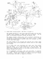
1
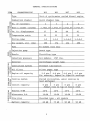
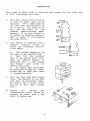
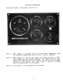
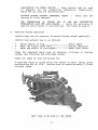
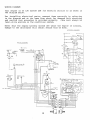
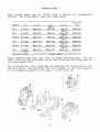
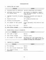
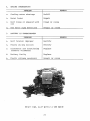
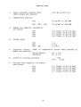
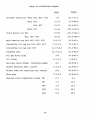
-( £ R II .., " ~ ~*III' -t q '" D"'" OPERATORS MANUAL MARINE DIESEL ENGINES W-13, W-21 , W-27, W-33 PUBLICATION NO. 32363 t~ rWESTERBEKE ~ I WESTERBEKE CORPORA TlON' 150 JOHN HANCOCK ROAD MYLES STANDISH INDUSTRIAL PARK· TAUNTON MA 02780 WEBSITE: WWW.WESTERBEKE.COM ~~ NAMIA Member National Marine Manufacturers Association z ••e CALIFORNIA PROPOSITION 65 WARNING Diesel engine exhaust and some of its constituents are known to the State of California to cause cancer, birth defects, and other reproductive harm. A WARNING Exhaust gasses contain Carbon Monoxide, an odorless and colorless gas. Carbon Monoxide is poisonous and can cause unconsciousness and death. Symptoms of Carbon Monoxide exposure can include: - Throbbing in Temples - Dizziness -Nausea - Muscular Twitching -Headache - Vomiting - Weakness and Sleepiness -Inability to Think Coherently IF YOU OR ANYONE ELSE EXPERIENCE ANY OF THESE SYMPTOMS, 6ET OUT INTO THE FRESH AIR IMMEDIATELY. If symptoms persist, seek medical attention. Shut down the unit and do not restart until it has been inspected and repaired. This WARNING DECAL is provided by WESTERBEKE and should be fixed to a bulkhead near your engine or generator. WESTERBEKE also recommends installing CARBON MONOXIDE DETECTORS in the living/sleeping quatters of your vessel. They are inexpensive and easily obtainable at your local marine store. FOREWORD Thank you for having selected a Westerbeke Diesel Engine for your use. This manual describes the procedures for proper handling and maintenance of the Engine Models W13, W21, W27 and W33. To maintain your engine always in its best operating condition and to enable it to perform best, it is important to handle it properly and carry out complete maintenance according to this manual. If you have any questions about your engine or in the event of a failure, please contact your nearest distributor or dealer. We look forward to your continued patronage. LEFT SIDE~ W-21 WITH 2:1 HBW-50 TRANSMISSION I TABLE OF CONTENTS PAGE GENERAL SPECIFICATIONS ••.•••••••.•••• 3 CAUTIONS IN HANDLING ENGINE ••.•••..•• 4 1. BREAKING IN..................... 5 2. PREPARATIONS. • • • • • • . • • • • • • • • . • •• 6 3. STARTING PROCEDURES ••..........• 7 4. STOPPING PROCEDURES •••.•••••..•• 10 5. CAUTIONS ON STARTING AND OPERATION •••..••••.••••••••• 10 6. REQUIREMENTS FOR PROPER OPERATION 6-1 Lubrication System •.•...••• 12 6-2 Fuel System ••....•...•••.•• 13 6-3 Cooling Systern .••..•••.•••• 15 6-4 Wiring diagrarn ••.•••••.•••• 1S 7. RECOMMENDED MAINTENANCE SERVICE.19 S. TRANSMISSIONS ••••.••..••.••••••. 22 9. TROUBLESHOOTING ••••••••••.•••••• 23 10. SERVICE DATA ••••••••••.....••.•• 25 11. TABLE OF TIGHTENING TORQUES ••••• 26 2 GENERAL SPECIFICATIONS ITEM CHARACTERISTIC W13 W2l W27 W33 Type Vert.,4 cycle,water cooled diesel Combustion chamber Swirl chamber type en~ine CIl :z No. of cylinders 2 0 H rx:IE-! 4 4 3 :Z~ Bore & stroke (inches) ZI%.l Cu. In. displacement 37 60 80 91 Compression ratio 23 23 23 23 Firing order 1-2 1-3-2 298 374 HC.J t!)H rx:IH C.J rx:I ~ 2.76x3.07 2.87x3.07 2.87x3.07 3.07x3.07 CIl Dry weight, std. (lbs) 1-3-4-2 1-3-4-2 434 498 Fuel #2 diesel fuel only Injection pump Bosch type Nozzle Throttling type Injection pressure All models: Governor Centrifugal weight type Lubrication system Pressure lubrication C.JE-! HCIl Oil filter Filterp~Qer ~(f.l Engine oil capacity 2.5 qts 4.0 qts 4.0 qts 4.2 qts For accuracy, depend on dipstick markings ::1!! ....:trx:l rx:IE-! DCIl I%.l>t (f.l Z 0 H E-!::E: ~rx:I I ~>t ::> ....:t ~ ::E:jcooling system Hrx:l1 ....:tE-! ou) 8 ~!Coolant capacity 1707 lbs. type I I Forced circulation, water cooling by heat exchanger I I I 8 qts 6 qts 5 qts 8 qts Always fill to top of filler neck ....:t Starter V-HP 12-2 12-2 12-2 12-2 C.J::E: Hrx:I t:X:E-! E-!(f.l Alternator V-A 12-50 12-50 12-50 12-50 ~ CJ>t rx:ICIl Glow ....:t ! I rx:I plug lBattery capacity Sheathed trpe - all models 60 AH 3 75 AH 90 AH 90 AH CAUTIONS IN HANDLING ENGINE * Always use proper engine oil and watch oil pressure during operation. * Use clean fuel, free from impurities and water content. * Prevent entry of air and water into the fuel system. * In case the starter motor pinion fails to engage wi th the ring gear at the time of starting, turn on the starter swi tch again after the starter motor has come to a complete stop. * Prevent the temperature of cooling water from falling too low. * Pay attention to the color of exhaust gas. * Clean or replace the fuel filter and oil filter periodically. * Replenish or replace oil as specified. SAFETY PRECAUTIONS o~eration * Never put the engine in * Do not touch moving parts during operation. * Do not touch hot parts such as exhaust pipe, and do not place combustible materials there. * Inspect and adjust parts of the engine only after it is stopped. * Check and refill engine oil, engine is brought to a stop. * In checking the level of and refilling cooling water, remove thie pressure cap after the temperature of the water has fallen enough. * Always use vicing. tools of proper in improperly ventilated places. cooling sizes 4 and water full and fuel after caution during the sel BREAKING IN Service life of your engine is dependent upon how your engine operated and serviced during the initial 50 hours of operation! is Your new engine needs 50 hours of conditioning operation for breaking each moving part in and maximizing performance and life of engine. Perform this conditioning carefully, bearing the following points in mind: CAUTION: Idle and warm up your engine from 3 to 5 minutes. * * * Avoid hasty acceleration. * Inspect, maintain and service your engine in accordance wi th the instructions in this manual. Use caution not to overload the engine. Explanation: "Breaking in" a new engine is basically a seating of the piston rings to the cylinder walls. This is not accomplished by long periods of running idle, nor by early running under full load, nor by varying loads with intervals of fast acceleration and/or excessive speed. Idle running may glaze the cylinder walls causing oil consumption and smoky operation. Excessive speeds and loads may score cylinder walls with similar results. As indicated above, use a short warm up at idle and put engine under moderate load and speed for the first ten hours of operation. For the next forty hours, use approximately 70% load. This kind of careful operation will result in best results from your engine. 5 PREPARATIONS Take steps as shown below in starting your engine for the first time or after a prolonged shut-down. 1. Fill your engine with oil up to or near the upper limit on the dipstick. Use a good grade of oil wi th API specification of CC or better. For quantity of oil, you may refer to the General Specifications page. However, it is best always to be guided by dipstick measurement as angle of installation has some effect. 2. Your eng ine is suppl ied wi th a coolant recovery system to which the following instructions apply: $ a) Fill engine completely to the neck of the manifold cap. b) Then fill the recovery tank to the bottom level line. Need for adding coolant is indicated when a cold engine has coolant level below the bottom level line. c) In winter add antifreeze as described on page 16. Antifreeze may be used year round if changed annually. 3. Fill the fuel tank with Diesel fuel. The interior of the fuel tank must be maintained clean. Be careful not to allow introduction of dirt when filling fuel. 4. Engine oil, coolant and transmission levels should be checked at least once a day prior to engine use. 6 ... ~\ ot1levelgatJge_~"'f1 and/i/lerpDrt STARTING PROCEDURES Instrument panel, description and use of: Note 1: When engine is stopped after use, the water temperature and oil pressure gauges may stay at their running readings. Note 2: When engine is next to be used, turn start switch to "ON". The temperature and pressure gauges will "ZERO" and the voltmeter will register battery voltage. The electric fuel pump, mounted on the engine, will also begin to operate, purging any air accumulated in the system. Note 3: The engine is now prepared for starting. 7 STARTING PROCEDURES 1_ Turn the starter swi tch to the "ON" position_ If making an ini tial star t after lay-up, fuel filter servicing or repairs, allow fuel pump to work 15-25 seconds to purge the system of any air. Check that clutch is in neutral and that throttle is in full forward_ 2_ Glow plug preheating with key in "ON" position, push in about 1/4 inch or enough so that voltmeter indicates discharge. Hold key in depressed posi tion until glow plugs are sufficiently hot_ Follow Table below for preheating time. Quick-heat type (Yl14T) Atmospheric temperature Preheating time +s·c (+4l·F) or higher Approx. 10 sec_ +S·C (+4l-F) to -S-C (+23-F) A~rox. -SoC (+23·F) or lower Approx 30 sec. Limit of continuous use 3. 20 sec. 1 minute Proper glow plug function is indicated by voltmeter drop when key is depressed. This drop will be slight but discernible. If no voltage drop is noted, indicate it may defective glow plugs or a faulty preheat circuit (check for loose connection). 8 4. Starting Continuing to hold the key depressed, turn to the "START" position. The starter motor will run ther eby cr ank ing the engine. Hold throttle open until engine runs and then reduce throttle. Should the eng ine not star t even when the star ter swi tch is left at "5" position for 10 seconds, take your hand off the starter switch for 30 seconds, and then attempt to start the engine again by sufficiently preheating the glow plug. The starter motor should never be allowed to run for more than 30 seconds at a time. 5. Operation As soon as the engine has started, release the key. The key will automatically return to the "ON" position. Leave the key at "ON" dur ing oper ation. Check that with engine running, oil pressure and battery charge voltage are registering and that raw water is discharging with the exhaust. During engine operation, do not turn the key to "5 11 position. may damage the starter motor. 6. Warm-up operation Run a few minutes at II IDLE" position to assure that all functions are operating. Then operate under reduced load until water temperature rises into the 140-150· range. 9 This STOPPING PROCEDURE 1. Stop To stop the engine move the throttle control through the idle position to stop. As the throttle is moved past idle there will be increased resistance to movement because a spring loading must be overcome. Hold the throttle firmly against the pressure until the engine comes to a complete stop. 2. W-13 W21,27,33 Starter switch off Wi th the eng ine stopped, turn the star ter key back to "OFF" position. The battery will be discharged if the key is left at "ON" position. An engine alarm buzzer is provided to warn the operator of this possibili ty. Best precaution is always to remove the key. CAUTIONS ON STARTING AND OPERATION 1. Normal starting Follow the procedures below for routine starting of your engine. 1) 2) 3) 4) 5) 2. Check the engine and transmission oil levels and refill if necessary. Insure that you have sufficient fuel. Keep tank as full as possible. Check coo~ng water level, and refill if necessary. Note: Check for leaks of water or oil, particularly when signs of such leak are found on the bottom of the engine or in the drip tray. Start the engine in accordance with the procedures given on the preceding pages. Allow the engine to warm up to 140·-150· F before placing the engine under heavy load. Starting under cold conditions The following three adverse condi tions concur as the atmospher ic temper a-ture drops exceedingly, and the engine must, under such conditions, be started by taking steps described below: 10 LUBRICATING OIL TURNS VISCOUS Make certain that oil used is adequate for the prevailing atmospheric temperature. Check the oil also for deterioration. VOLTAGE ACROSS BATTERY TERMINALS battery is fully charged. DROPS Check that the THE TEMPERATURE OF INTAKE AIR IS LOW AND COMPRESSION TEMPERATURE DOES NOT RISE ENOUGH Allow the glow plug to operate sufficiently to aid starting. See table on page 8. 3. Cautions during operation Confirm that the oil pressure is normal during normal operation. Confirm that exhaust gas is as follows: * * * While engine is cold •••••.••••••••••.•••• White smoke When the engine grows warm .•..•••.......• Almost smokeless When the engine is overloaded •••••••••••• Some black smoke Check for abnormal noise such as knocking, sounds, and vibration and blow-back sounds. fr iction or leaking Check for leaks of fuel and engine oil. A knocking sound is heard while the engine is cold, during quick acceleration and at idle. Confirm that no knocking sound is heard in other cases. LEFT SIDE} W-33 WITH 2:1 VEE DRIVE 11 REQUIREMENTS FOR PROPER OPERATION LUBRICATION SYSTEM 1. Engine oil For engine lubrication, use diesel engine oil. Diesel engine oils are classified according to the API Specifications into grades CA, CB, CC and CD. Anyone of them is usable, but use of CC or higher grades prepared by well-known makers is recommended. 2. Engine oil viscosity Use oil having viscosity best suited to the atmospheric temperature. Use of an all-season oil SAEIOW-30 with minimum viscosity change under different temperatures is suggested. Viscosity Atmospheric temperature 20·C (6a·F) or higher SAE 30 or lOW-30 SAE 20 or 10W-30 S·C (41·F) or lower SAE 10W-30 3. Oil pressure The oil pressure dur ing operation of the engine is indicated by the oil pressure gauge. During normal operation •••••••••••• Oil pressure will range between 50 and 70 PSI. At the time of cranking •••••••••••• Pressure will rise proportionately with speed. 4. Engine oil change To renew engine oil, discharge old oil through the sump drain hose attached at front of engine while engine is still warm. Drain old oil completely, replace the hose, plug the end securely and add fresh oil through the oil inlet port on the valve cover. After refilling oil, idle the engine for several minutes and stop. Then check the quanti ty of oil by the oil level gauge. F ill to but not over the high mark on the dipstick. 12 5. Replacement of oil filter Being a replaceable cartridge type, the oil filter requires no cleaning inside. In installing the oil filter, apply engine oil thinly on to the O-ring, and then tighten it by hand firmly. When removing the used filter, cover over with a plastic bag. This will allow both filter element and spilled oil to be collected cleanly without spilling oil in the bilge. Note A: After market filters are not recommended since the material standard or diameters of important items might be entirely different from genuine parts. Note B: Immediately after filter change and oil fill, run engine to ensure that oil pressure is normal and that there are no oil leaks. FUEL SYSTEM 1. Diesel fuel USE #2 DIESEL FUEL. NEVER USE KEROSENE OR HEAVY OIL. In cold weather, particularly, much water vapor is produced when much air is present in the fuel tank. The tank, therefore, should be kept full as much as possible. The fuel tank, furthermore, needs to be kept completely free of dirt and water. 2. To this end, it is most desirable that a primary fuel filter of the water entrapment type be installed between the fuel tank and engine. Such a filter is available under part # 32974. (See your local dealer.) Water entrapment filter #32974 is shown opposite. Inspect frequently for presence of water in the clear bowl. Drain it off by loosening the air vent and opening the drain. 13 3. Notes on fuel system See below a typical exploded view of a fuel system. The one shown is for the W13. Those for the W21, W27 and W33 are similar except for the number of cylinders. The Wes·terbeke self-bleeding fuel system is automatic in operation. Therefore, it is unlikely that the operator will be forced to service the system at sea. For. that unlikely possibility, however, it is recommended that the following parts be carried onboard. Banjo washers 11, 30, 31, 33, 34, 45 Injector seat washers 42 Lift pump filter and gaskets 6, 7, 8 Fuel filter element and gaskets 13, 14 ,15 14 If a leak should develop at a banjo or washer that cannot be remedied by a simple tightening of the screw, renew the washers. The engine can be started by taking the steps described on pages 8 and 9. In cases where the engine cannot be started easily, loosen two injection nuts on the nozzle side, turn the speed control lever to "full open" position, turn the starter motor and then tighten the nuts firmly. 4. Cleaning fuel filter and replacing filter element After the first 50 hours of operation, loosen the retainer ring #16 and discard filter element #15. Clean bowl #17 and re-install new filter, using new gasket #13 and #14. This same treatment is required of the filter element #6 in the fuel lift pump. Similarly, replace n.ew filter element #6 using new gasket #7 and #8. After the first 50 hour change, the change period may be increased to 200 hours or once per season. 5. Fuel injection pump The fuel injection pump is one of the most important components of the diesel engine and thus it calls for the utmost caution in handling. Furthermore, the fuel injection pump has been thoroughly shop-adjusted and should never be readjusted carelessly. Such adjustment, whenever necessary, should be performed at an author i zed service station as a precision pump tester and skills are required. To obtain long and satisfactory use of your injection pump: Always use fuel which is free from impurities. Clean and renew the fuel filter periodically. Inspect water entrapment filter regularly. COOLING SYSTEM 1. Cooling water As cooling water, use soft water with least impurity content as tap water (potable water) or rainwater, and never use water or foul water. Use of hard water or water containing impurity will lead to collection of scale in the engine and exchanger with resultant decline in cooling effects. 2. such hard much heat Antifreeze In cold districts, care should be takeri to prevent cooling water from freezing. Cooling water when frozen expands to break the 15 heat exchanger and the cylinder block, and it is essential that antifreeze be added to cooling water in a quantity being proportional to the lowest temperature of the d~str ict. It is recommended that the antifreeze mixture be used throughout the year. *Antifreeze of poor quality will cause corrosion of the cooling system, and thus always use antifreeze prepared by a reliable maker, and never use it mixed with antifreeze of a different brand. *Make sure that the cooling system of the engine is cleaned well before adding antifreeze. *Recommended antifreeze for year round use is ZEREX Long Life Coolant (antirust contained). ANTIFREEZE ADDITION DATA Antifreeze Concentration % 13 23 30 35 ·C Freezing temperature ( • F) -5 (23) -1" (14) -IS (5) -20 (-4) Note: 3. 45 -30 (-22) 60 50 -40 (-40) -50 (-58) It is advisable that antifreeze concentration be selected on the basis of a temperature which is about 5·C (lO·F) lower than the actual atmospheric temperature. Alternator belt tension The alternator belt is properly tense if it deflects 10 to 12 mm (0.39 to 0.47 in) as it is depressed with a finger between the pulley and pulley of the long distance side. Excess i ve tens ion can cause quick wear of the belt and bearings of the water pump and the alternator. Excessive slackness or presence of oil on the belt, on the other hand, can lead to engine overheating and insufficient charging due to a slipping belt. CAUTION: Never attempt to adjust engine is in operation. tension of 16 the fan belt while the 4. Fresh water cooling system (See Note 5 on page 6.) The system consists of a sea water pump which pumps raw sea water through a heat exchanger to remove heat from the coolant. The raw water is discharged overboard through the exhaust line. The engine coolant (fresh water with or without antifreeze) is circulated by the fresh water pump in continuous circuit. Pumped through the cylinder block, cylinder head, heat exchanger and back to the fresh water pump. The total system is very reliable and requires only a daily check of the water level in the system plus routine check of hose clamps and fittings. It is likely that zinc electrodes will waste away from contact wi th sea water. It is also possible for the raw water pump impeller to fail due to lack of sea water or deterioration. An early sign of impeller failure is less water and more steam at the exhaust through hull fitting. I t is recommended, therefore, that zinc electrodes, an impeller kit, a pump belt and a thermostat with gasket be kept onboard at all times. These parts should be ordered from your nearest stocking dealer and used as inspection dictates. 17 WIRING DIAGRAM Your engine is of l2V system and its electric circuit is as shown in the diagram below. For installing electrical parts, connect them correctly by referring to the diagram and at the same time check for damaged wire sheathing Care must always be and confirm that grounding is provided properly. taken while working on the electrica~ system. Never shut the engine battery switch off while the engine is running. Damage to the alternator will result should this be done • .,CYEMAnc + IZVDe DIAGRAM fI ...i'T'f,. ... ST~A:rtA STo\RT 500L t--------t ® "1.'1' (IIitN"TOA WIP: NG ',. DIAGRAM @ OUTPUT @"'Cjw~1 @f ~:ioU NOTE- W.T.~cNOER ~ (.11\ ~ CIoQ£ ... !:.l'" .RH &IHI C::_-="-+-I---. I~ \0 , !!JIHj ~.,[1.. ~ AL"rERNATOR 0 ® @ PR(-H(AT SOL @SI


![LS5105 Document No 2 [PDF 1MB] - Australian Electoral Commission](http://vs1.manualzilla.com/store/data/005655823_1-2458abda02bbd8390d0ac9ba8bd86ac6-150x150.png)