1
®
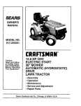
MODEL NUMBER 917.256543
OWNER'SMANUAL
° Assembly
° Operation
° Customer Responsibilities
o Service and Adjustments
o Repair Parts
CAUTION:
Read and follow
all safety
rules and instructions
before
operating
this equipment.
FOR CONSUMER ASSISTANCE HOT LINE, CALL THIS TOLL FREE NUMBER: t-800-659-5917
•
,, ,_,, ......
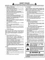
SAFETY RULES
_lb
Safe Operation
Practices
for Ride-On
Mowers
,_
IMPORTANT:
THIS CUTTING MACHINE IS CAPABLE OF AMPUTATING
HANDS AND FEET AND THROWING
OBJECTS.
FAILURE TO OBSERVE THE FOLLOWING SAFETY INSTRUCTIONS
COULD RESULT lN SERIOUS INJURY OR DEATH,
!11. CHILDREN
I.
GENERAL
•
Read, understand, and follow all instructions in the manual
and on the machine before starting..
Only allow responsible adults, who are familiar with the
instructions, to operate the machine.
Clear the area of objects such as rocks, toys, wire, etc,
which couId be picked up and thrown by the blade..
Be sure the area is clear of other people before mowing. Stop
machine if anyone enters the area.,
Never' carry passengers.
Do not mow in reverse unless absolutely necessary. Always
look down and behind before and while backing.
Be aware of the mower discharge direction and do not point
it at anyone
Do not operate the mower without either the
entire grass catcher or the guard in place.
Slow down before turning
Never leave a running machine unattended. Always turn off
blades, set parking brake, stop engine, and remove keys
before dismounting
Turn off blades when not mowing.
Stop engine before removing grass catcher or unclogging
chute_
Mow only in daylight or good artificial light
Do not operate the machine while under the influence of
alcohol or drugs.
Watch for traffic when operating near or crossing roadways.
Use extra care when loading or unloading the machine into
a trailer or truck
•
,,
•
•
•
•
•
•
•
•
•
•
•
•
II.
SLOPE
OPERATION
Tragic accidents can occur if the operator is not alert to the
presence of children. Children are often attracted to the
machine and the mowing activity.
Never assume that
children will remain where you last saw them_
•
Keep chitdrenoutofthe mowing area and under thewatchful
care of anotherresponsibleadult.
•
Be alert and turnmachine off ifchildren enterthe area.
•
Beforeand when backing, look behind and down for small
children.
•
Never carry children. They may fall off and be seriously
injuredor interfere with safe machineoperation_
•
Never allowchildrento operatethe machine.
•
Use extra care when approachingblind corners, shrubs,
trees,or otherobjectsthat may obscurevision
IV.
SERVICE
•
Use extra care in handling gasoline and other fuels. They are
flammable and vapors are explosive_
Use only an approved container
•
•
OPERATION
•
Slopes are a major factor related to Ioss-of-controt and
tipover accidents, which can resutt in severe injury or
death All slopes require extra caution. If you cannot back
up the slope or if you feel uneasy
•
on it, do not mow it.
•
DO:
•
Mow up and down slopes, not across.
•
Remove obstacles such as rocks, tree limbs, etc
.
Watch for holes, ruts, or bumps.
Uneven terrain could
overturn the machine. Tall grass can hide obstacles..
°
Use slow speed. Choose a low gear so that you will not have
to stop or shift while on the slope
.
Follow the manufacturer's
recommendations
for wheel
weights or counterweights to improve stability.
•
Use extra care with grass catchers or other attachments.
These can change the stability of the machine°
°
Keep all movement on the slopes slow and gradual Do not
make sudden changes in speed or direction
•
Avoid starting or stopping on a slope. If tires lose traction,
disengage the blades and proceed slowly straight down the
slope
•
•
•
•
Never remove gas cap or add fuel with the engine
running Allow engine to cool before refueling Do not
smoke.
Never refuel the machine indoors.
Never store the machine or fuel container inside where
there is an open flame, such as a water heater.
Never run a machine inside a closed area.
Keep nuts and bolts, especially blade attachment bolts, tight
and keep equipment in good condition
Never tamper with safety devices
Check their proper
operation regularly.
Keep machine free of grass, leaves, or other debris build-up.
Clean oil or fuel spillage. Attow machine to cool before
storing
Stop and inspect the equipment if you strike an object°
Repair, if necessary, before restarting
Never make adjustments or repairs with the engine running.
Grass catchercomponents are subjectto wear, damage, and
deterioration, which could expose moving parts or allow
objects to be thrown. Frequentfy check components and
replace with manufacturer's recommended parts, when necessary.
Mower blades are sharp and can cut Wrap the blade(s) or
wear gloves, and use extra caution when servicing them
Check brake operation frequently.
Adjust and service as
required.
Look for this symbol to point out important
safety
precautions.
It
means
CAUTIONIt!
BECOME ALERTltl
YOUR
SAFETY IS INVOLVED.
DO NOT:
•
Do not turn on slopes unless necessary, and then, turn slowly
and gradually downhill, if possible
•
Do not mow near drop-ofts, ditches, or embankment& The
mower could suddenly turn over if a wheel is over the edge
of a cliff or ditch, or if an edge caves in.
•
Do not mow on wet grass. Reduced traction could cause
sliding,
•
Do not try to stabilize the machine by putting your foot on the
ground,.
•
Do not use grass catcher' on steep slopes,
u u mmmnmn
CAUTION: Always disconnect spark plug
wire and place wire where it cannot contact
spark plug in order to prevent accidental
starting when setting up, transporting,
adjusting or making repairs.
WARNING &
The engine exhaust from this product contains
chemicals known to the State of California to
cause cancer, birth defects, or other reproductive harm.
2
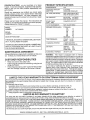
PRODUCT
CONGRATULATIONS
on your purchase of a Sears
Tractor. It has been designed, engineered and manufactured to give you the best possible dependability and
performance°
Should you experience any problem you cannot easily
remedy, please contact your nearest Sears Authorized
Service CentedDepartment°
We have competent, weIF
trained technicians and the proper tools to service or repair
this tractor°
Please read and retain this manual. The instructions will
enable you to assemble and maintain your tractor properly.
Always observe the "SAFETY RULES".
MODEL
NUMBER
SPECDFICATmONS
HORSEPOWER:
15.0
GASOLINE CAPACITY
AND TYPE:
5 QUARTS
UNLEADED
OiL TYPE (API_SF/SG):
SAE 10W30 (above 32°F)
SAE 5W-30 (below 32°F)
OIL CAPACITY:
W/FILTER:
W/O FILTER:
SPARK PLUG:
(GAP: .040")
CHAMPION RCt2YC
VALVE CLEARANCE:
NOT ADJUSTABLE
GROUND SPEED (MPH):
FORWARD:
1st
2nd
3rd
4th
5th
6th
REVERSE:
TIRE PRESSURE:
FRONT:
REAR:
CHARGING SYSTEM:
3 AMPS BATTERY
5 AMPS HEADLIGHTS
BATFERY:
AMP/HR:
MIN. CCA:
CASE SIZE:
BLADE BOLT TORQUE:
30-35 FT., LBS
917,256543
SERIAL
NUMBER
DATE OF PURCHASE
THE MODELAND SERIAL NUMBERSWILL BE FOUNDi
ON A PLATE UNDER THE SEAT.
YOU SHOULD RECORD BOTH SERIALNUMBE_R AND
DATE OF PURCHASE AND KEEP IN A SAFE PLACE
FOR FUTURE REFERENCE°
MAINTENANCE
AGREEMENT
A Sears Maintenance
Agreement
ucto Contact your nearest Sears
CUSTOMER
o
o
is available on this prodstore for details.
REGULAR
40 PINTS
3.5 PINTS
11
14
2 3
3 5
&5
5.7
1.8
t4 PSi
t0 PSi
30
240
U1R
WARNING;
This tractor is equipped
with an internal
combustion
engine and should not be used on or near any
unimproved
forest-covered,
brush-covered
or grass-cow
ered Iand unless the engine's exhaust system is equipped
with a spark arrester meeting applicable local or state laws
(if any) If a spark arrester is used, it should be maintained
in effective working order by the operator.
In the state of California
the above is required
by law
(Section 4442 of the California
Public Resources
Code).
Otherstates
may have similar laws
Federal iaws apply on
federal lands. A spark arrester for the muffler is available
through your nearest Sears Authorized
Service Center/
Department
(See REPAIR PARTS section of this manual).
RESPONSiBiLiTiES
Read and observe the safety rules.
Follow a regular schedule in maintaining, caring for and
using your tractor°
Follow the instructions
under "Customer Responsibilities" and "Storage" sections of this owner's manual.
i
UIVlaTED TWO YEAR WARRANTY
ON CRAFTSMAN
RiDiNG EQUIPMENT
For two (2) years from the date of purchase, if this Craftsman Riding Equipment is maintained, lubricated and tuned up according to
the instructions in the owner's manual, Sears will repair or replace, free of charge, any parts found to be defective in material or
workmanship.
This Warranty does not cover:
,,
Expendable items which become worn during normal use, such as blades, spark plugs, air cleaners, belts, etc.
=
Tire replacement or repair caused by punctures from outside objects, such as nails, thorns, stumps, or glass.
=
Repairs necessary because of operator abuse, negligence, improper storage or accident or the failure to maintain the
equipment according to the instructions contained in the owner's manual
o
Riding equipment used for commercial or rental purposes.
LliVliTED 90 DAY WARRANTY
ON BATTERY
Fer ninety (90) days from date of purchase, if any battery included with this riding equipment proves defective in material or
workmanship and our testing determines the battery will not hold a charge, Sears will replace the battery at no charge
IN-HOME WARRANTY SERVICE ON YOUR CRAFTSMAN RIDING EQUIPMENT IS AVAILABLE AT NO-CHARGE FOR 30 DAYS
FROM THE DATE OF PURCHASE
PLEASE CONTACT YOUR NEAREST SERVECE CENTER, AFTER 30 DAYS FROM THE
DATE OF PURCHASE, WARRANTY SERVICE IS AVAILABLE BY TAKING YOUR CRAFTSMAN RIDING EQUIPMENT TO YOUR
NEAREST SEARS SERVICE CENTER. (IN-HOME WARRANTY SERVICE WILL STILL BE AVAILABLE AFTER 30 DAYS FROM
THE DATE OF PURCHASE BUT A STANDARD TRIP CHARGE WILL APPLY-) THIS WARRANTY APPLIES ONLY WHILE THIS
PRODUCT IS IN THE UNITED STATES.
This Warranty gives you specific legal rights, and you may also have other rights which may vary from state to state
SEARS,
ROEBUCK
AND COo, D/817 WA, HOFFMAN
3
ESTATES,
IL 60179
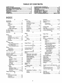
TABLE OF CONTENTS
SAFETY RULES ............................................................
2
PRODUCT SPECIFICATIONS ......................................
3
CUSTOMER RESPONSIBILITIES ..................... 3, 15"19
WARRANTY ..................................................................
3
TABLE OF CONTENTS .............................. ................... 4
ASSEMBLY ...............................................................
7"9
OPERATION ..........................................................
10-14
MAINTENANCE SCHEDULE .....................................
15
SERVICE AND ADJUSTMENTS ........................... 20-25
STORAGE ...................................................................
26
TROUBLESHOOTING ...........................................
27-28
REPAIR PARTS - TRACTOR ................................ 30-47
REPAIR PARTS - ENGINE ................. :.................. 48-53
PARTS ORDERING/SERVICE .................. BACK PAGE
UNDEX
A
Engine:
Accessories ............................................................
5
Air Filter .................................................
18
Adjustments;
Air Screen ..................................................
t8
Brake
22
Cooling Fins, Engine ........................t8
Carburetor ...................................... 25
Oil Change .........................................
17
Mower:
Oil Level ..........................................
I3,17
Front_To=Back ........................ 21
Oi{ Type .............................................17
Side-To-Side ..............................21
Preparation ................................... 13
Throttle Control Cable ....................24
Repair Parts ............................ 48-53
Air Filter, Engine ...............................................
18
Starting .................._......................... 14
Air Screen, Engine ............................. 18
Storage ......................................................
26
F
Assembly ..................................................7-9
B
Filters:
Air ...................................................................
18
Battery:
Fuel ................................................... t g
Charging ..............................................8
Fuel:
Cleaning .......................................... t7
Starting with Weak Battery ......... 23
Type ...........................................................
13
Storage ......................................................
26
Storage .............................................26
Terminals ..............................................
17
Fuse ........................................................ 24
Belts:
G
Motion Drive
Gauge Wheels .............................................
9
Removal/Replacement .............22
H
Mower' Blade Drive
Hood Removal/lnsiallation ........................
24
RemovailReplacement .................
22
L
Blade:
Leveling Mower Deck .......................... 21
Sharpening ................................................
16
Lubrication Chart ..........................................
15
Replacement .................................. 16
M
Brake Adjustment ................................ 22
....................................................
C
Carburetor Adjustment ......................... 25
Controls, Tractor ..............................................
11
Customer Responsibilities ................I5-19
Engine:
Air Filter o.........................................
18
Air Screen, Engine ..........................
18
Battery ......................................... 17
Cooling Fins, Engine .........................
18
Engine Oil ................................. 17
Fuel Filter ................................... 1g
Spark Plugs ................................ 19
Tractor:
Blades ...........................................16
Lubrication Chart ...................... 15
Maintenance Schedule ................
!5
Tire Care ..............................9,16,23
Cutting Height, Mower, ........................... 12
E
Maintenance Schedule ....................... 15
Mower:
Adjustment, Front-to-Back .......... 21
Adjustment, Side-to-Side ............ 21
Blade Sharpening ............................16
Blade Replacement .........................16
Cutting Height .............................. 12
Installation .................................... 20
Operation ........................................ 13
Removal ........................................ 20
Mowing Tips ......................................... 14
Muffler .................................................
19
Spark Arrester .................................
3,40
Mulcher Plate .......................................................
9
O
Oil:
Cotd Weather Conditions ....... 13,17
Engine .......................................... 17
Storage .................................................
26
Electrical:
Interlocks and Relays ......................
24
Schematic ...........................................
29
Wiring Diagram ............................. 30
4
Operation ...............................................
10-14
Operating Mower ................................................
13
Options:
Accessories
...............................................
5
Spark Arrester ............................ 3,40
P
Parking Brake .............................................
11-12
Parts Bag .........................................................
6
Parts, Replacement/Repalr
.................
30-47
Product Specifications ........................................
3
R
Repair Parts
30-47
.......................................
S
Safety Rules ..........................................................
2
Seat ..............................................................8
Service and Adjustments ............... 20-25
Brake .............................................. 22
Carburetor ...................................... 25
Fuse .......................................................
24
Hood Removal/tnstallation ........... 24
Motion Drive Belt
Remova!/Replacement
...............
22
Mower Blade Drive Belt
Removal/Replacement
.............22
Mower Adjustment:
Front-to-Back
21
Side4o-Side _............................ 21
Mower Installation ................................
20
Mower Removal ........................... 20
Tire Care ....................................
9,16,23
Slope Guide Sheet .......................................
55
Spark Plugs ........................................... 19
Specifications ..................................................
3
Starting the Engine ...............................
13-14
Steedng Wheel .............................................
7,23
Stopping the Tractor, .......................... 12
Storage .................................................... 26
..................................
1'
Throttle Control Cable Adjustment ..... 24
Tires .........................................................
9,16,23
Trouble Shooting Chart .......................
27-28
Transaxle Repair Parts ......................46-47
W
Warranty ............................
,.......................................
3
Wiring Diagram .................................... 30
Wiring Schematic ......................................
29
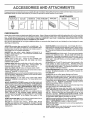
AOOE$$OR!
i1,, ii1,,11
, i,,
i
AND ATTACH
ENTS
i
These accessories and attachments were available through most Sears retail outlets and service centers when the tractor was purchased
Most Sears stores can order these items for you when you provide the model number of your tractor.
ENGINE
SPARK PLUG
MAINTENANCE
GAS CAN
ENGINE OIL
FUEL STABILIZER
AIR FILTER
BLADES
BELTS
PERFORMANCE
Sears offers a wide variety of attachments that fit your tractor.
you, This list was current at the time of publication; however,
may be made in these attachments, or some may no longer
accessories
and attachments
that are available for your
Most of these attachments do not require additional hitches
attaching and detaching
Many of these are listed below with brief explanations of how they can help
it may change in future years- more attachments may be added, changes
be available or fit your model. Contact your nearest Sears store for the
tractor.
or conversion kits (those that do are indicated) and are designed for easy
AERATOR promotes deep root growth for a healthy lawn, Tapered 2.5-inch steel spikes mounted on 10-inch diameter discs
puncture holes in soil at close intervals to let moisture soak in.
Steel weight tray for increased penetration.
BAGGER lets you collect grass clippings and leaves for a
healthier, heater looking lawn Two Permanex containers hold
30-gallon plastic bags.
BUMPER protects front end of tractor from damage..
CARTS make hauling easy. Variety of sizes available, plus
accessories such as side panel kits, tool caddy, cart cover,
protective mat and dolly
CORING AERATOR takes small plugs out of soil to allow moisture and nutrients to reach grass roots.. 36-inch swath. 24
hardened steel coring tips. 150 Ib capacity weight tray.
EASY OIL DRAIN VALVE makes oil changes easier, faster.
FRONT NOSE ROLLER canters in front of mower deck to reduce
chances of "scalping" on uneven terrain,
GANG HITCH lets you tow 2 or 3 pull-behind attachments at once,
such as sweepers, dethatchers, aerators (not for use with rollers,
carts or other heavy attachments).
GAUGE WHEELS on both sides of the mower deck reduce
chances of "scalping" on uneven terrain For mower decks not so
equipped.
MULCH RAKFJDETHATCHER loosens soil and flips thatch and
matted leaves to lawn surface for easy pickup_ Twenty spring fine
teeth. Usefulto prepare bare areas forseeding. Available for front
or rear mounting.
HIGH PERFORMANCE
REEL_AOTION
SPRING TINE DETHATCHER covers 36-inch wide path and
tosses thatch into large hopper Mounts behind tractor,.
MULCHING CLOSE-OUT PLATE KIT, once installed, lets you
mulch, discharge or bag clippings (bagger optional) without
changing blades_ For models not equipped as 3-in-1 Convertible
mowers. See "MOWER" in the Repair Parts section of this
manual.
RAMP TOPS AND FEET let you load and unload tractor from a
pickup truck Use with 2 x 8 or 2 x 10 lumber.
ROLLER for smoother lawn surface.
36-inch wide, 18-inch
diameter watePtight drum holds upto 390 Ibs, of weight. Rounded
edges prevent harm to turf Adjustable scraper automatically
cleans drum.
SNOW BLADE forsnow removal only. 14-inch high, 48-inch wk!,
blade clears 42-1nch path when angled left or right, Raises, Iower,s
with side lever_ Adjustable skids; replaceable, reversibiescraper
bar. (Use with tire chains and wheel weights and/or rear drawbar
weighL)
SNOWTHROWER has 40-inch swath. Drum-type auger handles
powdery and wet/heavy snow.. Mounts easily with simple pin
arrangement.. Discharge chute adjusts from tractor seat. 6-inch
diameter spout discharges snow I0 to 50 feet Liftcontrolled at
tractor seat. (Use with chains and wheel weights and/or rear
drawbar weight,)
SPRAYERS use 12-volt DC electric motor that connects to the
tractor battery or other 12-volt source,
Includes booms for
automatic spraying and hand held wand for spot spraying. Wand
has adjustable spray pattern. For applying herbicides, insecticides, fungicides and liquid fertilizers
SPREADERISEEDERS
make seeding, fertilizing, and weed killing easy, Broadcast spreaders are also useful for granuEar deicers and sand.
SWEEPERS let you collect grass clippings and leaves
TILLER has 5 hp engine and 36-inch swath to prepare seed beds,
cultivate and compost garden residue. Tiller has its own built-in
liftand depth control system and does NOT require a sleeve hitch
Fits any lawn, yard or garden tractor Sirnply hook up to the tractor
drawbar and go!
Optional
accessories
convert unit for
dethatching, aerating, hilling ,.without tools.
TIRE CHAINS are heavy duty; close{y spaced extra-large cross
links give smooth ride, outstanding traction.
TRACTOR CAB has heavy duty vinyl fabric over tubular steel
frame, ABS plastic top; clear plastic windshield offers 360 degree
visibility Hinged metal doors with catch. Keeps operator warm
and dry. Remove vinyl sides and windshields for use as sun
protector in summer
Optional accessories
include:
tinted!
tempered solid safety glass windshield with hand operated wiper;
12-volt amber caution light for mounting on cab top.
VACS for powerful collection of heavy grass clippings and leaves.
Optional wand attachment
to pick up debris in hard-to-reach
places, VAC/CHIPPER includes a chipper-shredder
WEIGHT BRACKET for drawbar for snow removal applications_
Uses (1) 55 Ib weight
WHEEL WEIGHTS for rear wheets provide needed traction for
snow removal or dozing heavy materials
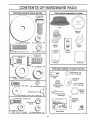
CONTENTS
OF HARDWARE
PACK
u ..................
Parts Bag contents
shown full size
(li Hex Bolt
3/8-16 x 1
©
Seat
Steering
Wheel
©
(1) Lockwasher
(1) Large Flat Washer
3/8
Mulcher
Plate
Steering
Boot
(1) Hex Bolt 5/16-18 x 1-1/4
(1) Locknut
Video
Cassette
5116-18
___ (1) Shoulder Bolt
5/16-18
Manual
(1) Lock Washer 1/2
©
..........
Parts bag contents
,,,,,,,,,,,,,, ........... ,,,,,
not shown
full size
x(2)7/8
Washers
x 14 Gauge
3/8
(2) Shoulder
(1) Washer
17/32 x 1-3/16 x 12 Gauge
_ws
Parts Bag
#10 x 518
Bolts
©
(2) Lock Washers
#10
(2) Gauge
_
(2) CenterWheels
_
lock Nuts
Steering Wheel
Adapter
Steering
Wheel
(2) Weld Nuts #10 _i
_(2)Washers
1
_ok
insert
Assembtys
3/16 x 3/4 x 16 Gauge
_::_2!HexBo!ts114-20
×3/4
.,/_'_
(2) Washers
_'_
Extension
Shaft
(2) Hex Nuts _"--'j/
1/4-20
-_
9/32 x 5/8 x 16 Gauge
I
(2) Keys
_"_
Lock Washers
teering
Slope Sheet
1/4
.................
6
i ......
,...................
,,
,, ,,,,,,,,,,ul,_
i,i ,,,,, i
lit,
.....
,
ASSE
.....
'
,
1,1,,
ii
...................
, i
....
i-,
LY
ÁÁÁ,,
Your new tractor has been assembled at the factory with exception of those parts left unassembled for shipping purposes°
To ensure safe and proper operation of your tractor all parts and hardware you assemble must be tightened securely_ Use
the correct tools as necessary to insure proper tightness°
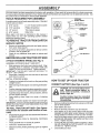
TOOLS REQUIRED
FOR ASSEMBLY
STEERING
A socket wrench set wilt make assembly easier_ Standard
wrench sizes are listed.
(1) 5/16" wrench
(2) 7/16" wrenches
I_ /
(1) 3/4" Socket w/drive rachet
Phillips Screwdriver
_...-
Tire pressure gauge
(1) 1/2" wrench
Utility knife
(1) 9/16" wrench
When right or left hand is mentioned in this manual, it
means when you are in the operating position (seated
behind the steering wheel)°
TO REMOVE TRACTOR
UNPACK
=
•
o
WHEEL INSERT
_
3t8 HEX BOLT
3'8 LOCK WASHER
STEERING
BOOT
FROM CARTON
CARTON
Remove all accessible loose parts and parts cartons
from carton (See page 6)_
Cut, from top to bottom, along lines on al! four corners
of carton, and lay panels fiat°
Check for any additional loose parts or cartons and
remove°
EXTENSION
SHAFT
ADAPTER
5/!6 HEX BOLT
BEFORE ROLLING TRACTOR OFF SKID
ATTACH
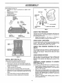
ASSEMBLE
STEERING
WHEEL
(See Fig. 1)
EXTENSION SHAFT AND BOOT
°
Slide extension shaft onto lower steering shaft Align
mounting holes in extension and lower shafts and
instail 5/16 hex bolt and Iocknuto Tighten securely_
IMPORTANT: TIGHTEN BOLT AND NUT SECURELY TO
18-22 FT. LBS TORQUE.
o
Place tabs of steering boot over tab slots in dash and
push down to secure.
INSTALL STEERING WHEEL
,
o
o
•
°
FIG. 1
HOW TO SET UP YOUR TRACTOR
Position front wheels of the tractor so they are pointing
straight forward
Slide steering wheel adapter onto steering shaft extension,
CONNECT
Positive terminal must be connected
first to prevent sparking from accidental grounding.
,,
o
o
TO ROLL TRACTOR OFF SKID (See Operation section for location and function
of controls)
o
•
°
o
Press lift lever ptunger and raise attachment lift lever to
its highest position.
Release parking brake by depressing clutch/brake
pedal°
Place gearshift lever in neutral (N) position.
Roil tractor backwards off skid.
Remove banding hoiding discharge guard up against
tractor.
(See Figs. 2 and 3)
CAUTION: Do not short battery terminals. Before connecting battery, remove metal bracelets,
wristwatch
bands, rings, etc.
Position steering wheel and sleeve assembly so cross
bars are horizontal (left to right) and slide onto adapter.
Assemble large flat washer, 3/8 Iock washer, 3/8 hex
bolt and tighten securely.
Snap steering wheel insert into center of steering
wheel.
o
Remove protective pfastic from tractor hood and grill
IMPORTANT; CHECK FOR AND REMOVE ANY STAPLES
IN SKID THAT MAY PUNCTURE TIRES WHERE TRACTOR
IS TO ROLL OFF SKID.
,
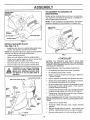
BATTERY
o
°
7
o
Remove cardboard packing from seat pan and lift seat
pan to raised position.
Open battery box door.
Remove terminal protective caps and discard
If this battery is put into service alter month and year
indicated on label (label located between terminals)
charge battery for minimum of one hour at 6-10 amps.
First connect RED battery cabte to positive (+) terminal
with hex bolt, flat washer, lock washer and hex nut as
shown° Tighten secure}y,
Connect BLACK grounding cable to negative (_) termF
hal with remaining hex bolt, flat washer, lock washer
and hex nut. Tighten securely.
Close battery box door.
Openbatteryboxdoorfor:
• Inspectionfor secureconnections
(to tightenhardware).
o Inspection
forcorrosion.
o Testingbattery.
o Jumping(if required).
o Periodiccharging.
SEAT
SEATPAN
SHOULDER
_
BOLT
DISCARD
TERMINAL
PROTECTIVE
CAPS
HUT
HEX
LOCK
WASHER
I
FLAT
WASHER
ADJUSTMENT
BOLT
LARGE FLAT WASHER
FIG, 4
HE](
BOLT
POSITIVE
(RED) CABLE
NEGATIVE
(BLACK)CABLE
FIG, 2
CHECK TiRE PRESSURE
The tires on your tractor were overinflated at the factory for
shipping purposes, Correct tire pressure is important for
best cutting performance.
.
Reduce tire pressure to PSI shown in "PRODUCT
SPECIFICATIONS" on page 3 of this manual.
CHECK
For best cutting results, mower housing should be properly
leveledo See "TO LEVEL MOWER HOUSING" in the
Service and Adjustments section of this manua!°
SEAT
PAN
CHECK
BELTS
BATTERY
BOXDOOR
FIG. 3
SEAT (See Fig. 4)
Adjust seat before tightening adjustment bolt.
= Remove cardboard packing on seat pan°
o Place seat on seat pan and assemble shoulder boil
o Assemble adjustment bolt, lockwasher and flat washer
loosely. Do not tighten.
Tighten shoulder bolt securely.
o
Lower seat into operating position and sit on seal
°
Slide seat until a comfortable position is reached which
allows you to press clutch/brake pedal all the way
down..
=
o
FOR PROPER
POSiTiON
OF ALL
See the figures that are shown for replacing motion and
mower blade drive belts in the Service and Adjustments
section of this manual, Verify that the belts are routed
correctly.
CHECK
INSTALL
DECK LEVELNESS
Get off seat without moving its adjusted position.
Raise seat and tighten adjustment bolt securely°
BRAKE SYSTEM
After you learn how to operate your tractor, check to see
that the brake is properly adjusted_ See '%0 ADJUST
BRAKE" in the Service and Adjustments section of this
manual
ASSEMBLE
GAUGE
WHEELS
TO
MOWER
DECK (See Fig. 5)
Assemble gauge wheels with tractor on a fiat level surface,,
o
Adjust mower' to desired cutting height (See "TO ADJUST MOWER CUTTING HEIGHT" in the Operation
section of this manual),
=
With mower in desired height of cut position, gauge
wheels should be assembled so they are slightly off the
ground° Install gauge wheel in appropriate hole with
shoulder bolt, 3/8" washer and 3/8-16 locknut and
tighten securely.
o
Repeat for opposite side installing gauge wheel in
same adjustment hole,
..........
i
..........
,,,
,.........
_,,,_ ....
illl,
i, ,,ll,,
LY
...............i............................
I
TO CONVERT
DISCHARGING
TO BAGGING
OR
Simply remove mulcher plate and store in a safe place.
Your mower is now ready for discharging or installation of
optional grass catcher accessory°
NOTE: It is not necessary to change blades.. The mulcher
blades are designed for discharging and bagging also.
DEFLECTOR
LOCKNUT
3/8" WASHER
_/SHOULDERBOLT
GAUGE WHEEL
FIG. 5
INSTALL IVlULCHER
(See Figs. 6 & 7)
PLATE
o
Install two latch hooks to mulcher plate using screw,
washer, lock washer, and weld nut as shown.
NOTE: Pre-assemble weld nut to latch hook by inserting
weld nut from the top with hook pointing down.
o
=
o
°
LATCH
HOOKS
FIG. 7
Tighten hardware securely.
Raise and hold deflector shield in upright position.
Place front of mulcher plate over front of mower deck
opening and slide into place, as shown,
Hook front latch into hole on front of mower deck°
Hook rear latch into hole on back of mower deck..
,/CHECKLIST
BEFORE YOU OPERATE AND ENJOY YOUR NEW
TRACTOR, WE WISH TO ASSURE THAT YOU RECEIVE
THE BESTPERFORMANCE AND SATISFACTION FROM
THIS QUALITY PRODUCT.
CAUTION: Do not remove discharge
guard from mower, Raise and hold
guard when attaching mulcher plate
and allow it to rest on plate while in
operation.
PLEASE REVIEW THE FOLLOWING
HOOK POINTS DOWN
LOCK
___
WASHER
\
NUT _
SCREW
,/
All assembly instructions have been completed°
_"
No remaining loose parts in carton.
,/
Battery is properly prepared and charged..
1 hour at 6 amps).
,./
Seat is adjusted comfortably and tightened securelyo
-
J
Be sure mower deck is properly leveled side-to-side/
front-to-rear for best cutting results° (Tires must be
properly inflated for leveling).
,/
Check mower and drive betts. Be sure they are routed
properly around pulleys and inside all belt keepers.
v"
Check wiring_ See that all connections are still secure
and wires are properly clamped_
_J/_
_
LATCH
WHILE LEARNING HOW TO USE YOUR TRACTOR, PAY
EXTRA ATTENTION TO THE FOLLOWING IMPORTANT
ITEMS:
LATCH
HOOK
LOCK
WASHER
WASHER
WELD
NUT
,/
Engine oil is at proper level..
,z
Fuel tank is filled with fresh, clean, regular unleaded
gasoline.
Become familiar with all controls - their location and
function° Operate them before you start the engine.
v"
WASHER
MULCHER
PLATE
v"
FIGo6
(Minimum
Z" All tires are properly inflated. (For shipping purposes,
the tires were overinflated at the factory).
WELDNUTFROMTH_O_---_
WELD
CHECKLIST:
9
Be sure brake system is in safe operating condition.
......................
ii
...ll
.i..uu....,
...i. ii....
u
OPERATION
......
i,u,,
i
, i
, li,
H
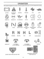
These symbols may appear on your tractor' or in literature supplied with the product° Learn and understand their meaning_
÷
BATTERY
CAUTION OR
WARNING
REVERSE
FORWARD
FAST
SLOW
ENGINE ON
ENGINE OFF
OILPRESSURE
CLUTCH
LIGHTS ON
LIGHTS OFF
FUEL
CHOKE
DIFFERENTIAL
LOCK
PARKING BRAKE
LOCKED
UNLOCKED
REVERSE
MOWER LIFT
'
MOWER HEIGHT
HIGH
NEUTRAL
ATTACHMENT
CLUTCH ENGAGED
LOW
PARKING BRAKE
IGNITION
ATTACHMENT
CLUTCH DISENGAGED
HYDROSTATIC
DANGER, KEEP HANDS AND FEET AWAY
FREE WHEEL
(Hydro Models only)
!0
OPERATION
ii,
,i ,,,i, i,, "IIII''M"= '"111"
'"111
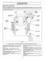
KNOW YOUR TRACTOR
READ
THIS
OWNER'S
MANUAL
AND
SAFETY
RULES
BEFORE
OPERATING
YOUR
TRACTOR
Compare the illustrations with your tractor to familiarize yourself with the locations of various controls and adjustments_ Save
.,this manual for future reference_
LIGHT
SWITCH
POSITION
IGNITION
SWITCH
AMMETER
THROTTLE]CHOKE
CONTROL
LIFT LEVER
PLUNGER
ATTACHMENT
LIFT LEVER
CLUTCH/
BRAKE
PEDAL
ATTACHMENT
CLUTCH LEVER
HEIGHT
ADJUSTMENT
KNOB
PARKING
BRAKE
GEAR SHIFT
LEVER
FIG. 8
Our tractors conform to the safety standards of the American National Standards Instituter
ATTACHMENT CLUTCH LEVER: Used to engage the
mower blades, or other attachments mounted to your
tractor°
LIGHT SWITCH:
GEAR SHIFT LEVER - Selects the speed and direction of
the tractor,
ATTACHMENT LIFT LEVER: Used to raise and lower the
mower deck or other attachments mounted to your tractor_
LIFT LEVER PLUNGER: Used to release attachment lift
lever when changing its position.
Turns the headlights on and off.
THROTTLE/CHOKE
speed.
CONTROL:
Used to control engine
CLUTCH/BRAKE PEDAL: Used fordeclutching
ing the tractor and starting the engine_
PARKING BRAKE:
brake position.
Locks clutch/brake
and brak-
IGNITION SWITCH:
engine°
pedal into the
Used for starting and stopping the
HEIGHT ADJUSTMENT
cutting height.
AMMETER:
(-)o
11
KNOB; Used to adjust the mower
Indicates battery charging (+) or discharging
The operation of any tractor can result in foreign objects thrown into the eyes, which can
result in severe eye damage. A!ways wear safety glasses or eye shields while operating your
tractor or performing any adjustments or repairs. We recommend a wide vision safety mask
over the spectacles or standard safety glasses.
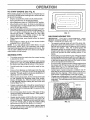
NOTE: Under certain conditions When tractor is standing
idle with the engine running, hot engine exhaust gases may
cause "browning" of grass. To eliminate this possibility,
always stop engine when stopping tractor on grass areas°
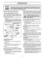
HOW' TO USE YOUR TRACTOR
TO SET PARKING
BRAKE
(See Fig. 9)
Your tractor is equipped with an operator presence sensing
switch. When engine is running, any attempt by the
operator' to leave the seat without first setting the parking
brake will shut off the engine.
.
Depress clutch/broke pedal into full "BRAKE" position
and hold.
o
Place parking brake lever in "ENGAGED" position and
release pressure from clutch/brake pedal Pedalshould
remain in "BRAKE" position= Make sure parking brake
wilt hold tractor secure_
ATTACHMENT CLUTCH
"ENGAGED" POSITION
THRCTrLFJCHOKE
CONTROL
CAUTION:
Always stop tractor completely, as described above, before leaving the operator's position; to empty
grass catcher, etc.
TO USE THROTTLE
Operating engine at tess than full throttle reduces the
battery charging rate.
=
Full throttle offers the best bagging and mower performance_
LEVER
"DISENGAGED"
PARKING DRAKE
"ENGAGED"
"BRAKE"
POSITION
GEARSHIFT
CLUTCHIBRAKE
PEDAL "DRIVE"
POSITION
HEIGHT ADJUSTMENT
KNOB
Start tractor with clutch/brake pedal depressed and
gearshift lever in neutral (N) position.
o
Move gearshift lever to desired
(See
Move attachment clutch lever to "DISENGAGED"
sition..
po-
GROUND DRIVE Depress clutch/brake pedal into full "BRAKE" position.,
lever to neutral (N) position..
Move throttle control to slow (_)
position.,
MOWER
CUTTING
HEqGHT
Fig. 9)
The cutting height is controlled by turning the height adjustment knob in desired direction,
(See Fig. 9)
MOWER BLADES -
o
o
TO ADJUST
°
Move gearshift
ENGINE -
is conbotled by the
o Slowly release clutch/brake pedal to start movement,
IMPORTANT: BRING TRACTOR TO A COMPLETE STOP
BEFORE SHIFTING OR CHANGING GEARS. FAILURE
TO DO SO WILL SHORTEN THE USEFUL LIFE OF YOUR
TRANSAXLE
FIG. 9
=
AND BACKWARD
The direction and speed of movement
gearshift lever°
"DISENGAGED"
POSITION
o
(See Fig. 9)
=
TO MOVE FORWARD
(See Fig, 9)
STOPPING
CONTROL
Always operate engine at full throttle.
positionu
NOTE: FaiIure to move throttle control to slow (_)
position and allowing engine to idle before stopping may
cause engine to "bacldire"o
o
Turn ignition key to "OFF" position and remove key.
Always remove key when leaving tractor to prevent
unauthorized use,
o
Never use choke to stop engine=
o
Turn knob clockwise ((-_4) to raise cutting height.
,,
Turn knob counterclockwise
height.,
(lf"_)
to lower cutting
The cutting height range is approximately 1-1/2" to4% The
heights are measured from the ground to the blade tip with
the engine not running° These heights are approximate
and may vary depending upon soil conditions, height of
grass and types of grass being mowe&
o
The average lawn should be cut to approximately2-1/2
inches during the cool season and to over 3 inches
during hot months° For heaIthier and better looking
lawns, mow often and after moderate growth°
=
For best cutting performance, grass ow, 6 inches in
height should be mowed twice. Make the first cut
relatively high; the second to desired height.
,
,i ii. ,i,,,,11,,,,,,,,11-,111,1
....
i.-m .............
OPERATION
TO OPERATE
MOWER
(See Fig. 10)
Your tractor is equipped with an operator presence sensing switch, Any attempt by the operator to leave the seat
with the engine running and the attachment clutch engaged
will shut off the engine.
o
o
Select desired height of cut
Lower mower with attachment lift control,
°
Start mower blades by engaging attachment
control°
°
TO STOP MOWER BLADES - disengage attachment
clutch control.
ii
To restart movement, slowly release parking brake and
clutch/brake pedal°
o
Make all turns slowly.
TO TRANSPORT
clutch
i,,
o
=
Raise attachment
ment lift control.
lift to highest position with attach-
°
When pushing or towing yourtractor,
lever is in neutral (N) position
.
Do not push or tow tractor at more than five (5) MPH.
be sure gearshift
NOTE: To protect hood from damage when transporting
your tractor on a truck or a trailer, be su re hood is closed and
secured to tractor, Use an appropriate means of tying hood
to tractor (rope, cord, etc.)o
,,i,,
CAUTION: Do not operate the mower
without either the entire grass catcher,
on mowers so equipped, or the discharge guard in place.
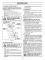
BEFORE
CHECK
STARTING
ENGINE
THE ENGINE
OIL LEVEL
(See Fig. 17)
•
The engine inyour tractor has been shipped, from the
factory, already filled with summer weight oil,
•
Check engine oil with tractor on level ground.
•
Unthread and remove oil fill cap/dipstick; wipe oil off.
Reinsert the dipstick intothe tube and rest oil fill cap on
the tube. Do not thread the cap onto the tube. Remove
and read oil level,, If necessary, add oil until "FULL"
mark on dipstick is reached, Do not overfill,
.
For cold weather operation you should change oil for
easier starting (See "OIL VISCOSITY CHART" in the
Customer Responsibilities section of this manual).
o
To change engine oil, see the Customer Responsibilities section in this manual
ADD GASOLINE
o
Fill fuel tank,. Use fresh: clean, regular unleaded
gasoline with a minimum of 87 octane° (Use of leaded
gasoline will increase carbon and lead oxide deposits
and reduce valve life). Do not mix oil with gasoline.
Purchase fuel in quantities that can be used within 30
days to assure fuel freshness
IMPORTANT: WHEN OPERATING IN TEMPERATURES
BELOW 32°F(0°C), USE FRESH, CLEAN WINTER GRADE
GASOLINE TO HELP INSURE GOOD COLD WEATHER
STARTINGo
FIG. 10
TO OPERATE ON HILLS
ii
hills with slopes greater than 15 ° and
CAUTION:
not drive
up or down
do not drive Do
across
any slope.
I
WARNING:
Experience indicates that alcohol blended
fuels (called gasohol or using ethanol or methanol) can
attract moisture which leads to separation and formation of
acids during storage
Acidic gas can damage the fuel
system of an engine while in storage
To avoid engine
problems, the fuel system should be emptied before storage of 30 days or longer. Drain the gas tank, start the
engine and let it run until the fuel lines and carburetor are
empty. Use fresh fuel next season. See Storage Instructions for additional information
Never use engine or
carburetor cleaner products in the fuel tank or permanent
damage may occur.
ii ,,,,,,,ll ,,i,,i,ii ,i
I
iI
L
.
Choose the slowest speed before starting up or down
hills.
.
Avoid stopping or changing speed on hills
.
If slowing is necessary, move throttle control lever to
slower position.
•
If stopping is absolutely necessary, push clutch/brake
_edal quickly to brake position and engage parking
rake.
-
CAUTION: Fill to bottom of gas tank
filter neck. Do not overfill. Wipeoffany
spilled oil or fuel. Do not store, spill or
use gasoline near an open flame.
Move gearshift lever to 1st gear. Be sure you have
allowed room for tractor to roll slightly as you restart
movement
13
.....
i
,
, i .........
i,
,, iii .........
i,,,U-,lllll ........
i,,11,,,1111
,,
L
,i
OPERATION
i ......
ii ...........................................
TO START
i, i ,11, i .............................
i,,
ENGIN _= (See Fig. 9)
When starting engine for the first time or if engine has run
out of fuel, it will take extra cranking time to move fuel from
the tank to the engine,
o
Depress clutch/brake pedal and set parking brake.
o Place gearshift lever in neutral (N) position_
o Move attachment clutch to "DISENGAGED" position.
o Move throttle control lever to choke (N) position for
ccldengine start. Forwarmenginestart,
movethrottte
control to fast (,_) position.,
= Insertkey into ignitionand turn keyclocfw_iseto"START"
position and release key as soon as engine starts. Do
not run starter continuously for more than fifteen
seconds per minute.. If engine does not start after
several attempts, move throttle control to fast (,_)
position, wait a few minutes and try again.
o When engine starts, move throttle control to desired
position°
o Allow engine to warm up for' a few minutes before
engaging drive or' attachments_
NOTE: If at a high altitude (above 3000 feet) or in cold
temperatures (below 32°F), the carburetor fuel mixture
may need to be adjusted for best engine performance. See
"TO ADJUST CARBURETOR" in the Service and Adjustments section of this manual.
f
r
FIG, 11
IVIULCHJNG iVtOWING TiPS
IMPORTANT:
FOR BEST PERFORMANCE,
KEEP
MOWER HOUSING FREE OF BUILT-UP GRASS AND
TRASH CLEAN AFTER EACH USE.
°
MOWING TUPS
•
Tire chains cannot be used when the mower housing
is attached to tractor.
o
Mower-should be properly leveled for best mowing
performance. See"TO LEVEL MOWER HOUSING" in
the Service and Adjustments section of this manual.
The left hand side of mower' should be used for trimming.
=
.
-
.
Drive so that clippings are discharged onto the area
that has been cut. Have the cut area to the right of the
machine. This will result in a more even distribution of
clippings and more uniform cutting..
o
°
When mowing large areas, start by turning to the right
so that clippings will discharge away from shrubs,
fences, driveways, etc,. After one or two rounds, mow
in the opposite direction making left hand turns until
finished (See Fig_ 11 )o
o
o
If grass is extremely tall, it should be mowed twice to
reduce load and possible fire hazard from dried clippings. Make first cut relatively high; the second to the
desired height.
o
Do not mow grass when it is Wetr. Wet grass will plug
mower and leave undesirable clumps° Allow grass t,._
dry before rnowing_
o
Always operate engine at full throttle when mowing to
assure better mowing performance and proper discharge of material Regulate ground speed by selecting a low enough gear to give the mower cutting
performance as well as the quality of cut desired.
°
The special mulching blade will recut the grass clippings many times and reduce them in size so that as
they fall onto the lawn they will disperse into the grass
and not be noticed_ Also, the mulched grass will
biodegrade quickly to provide nutrients for' the lawn.
Always mulch with your highest engine (blade) speed
as this wilt provide the best recutting action ot the
biades.
Avoid cutting your lawn when it is weL Wet grass tends
to form clumps and interferes with the mulching action°
The best time to mow your Dawnis the early afternoon.
At this time the grass has dried and the newly cut area
will not be exposed to the direct sun.
For best results, adjust the mower cutting height so that
the mower cuts off only the top one-third of the grass
blades (See Fig. 12). For extremely heavy mulching,
reduce your width of cut and mow slowly.
Certain types of grass and grass conditions may require that an area be mulched a second time to completely hide the clippings. When doing a second cut,
mow across or perpendicular to the first cut path,
Change your cutting pattern from week to week. Mow
north to south one week then change to east to west the
next week. This will help prevent matting and graining
of the lawn.
MAX 1/3
FIG. t2
When operating attachments, select a ground speed
that will suit the terrain and give best performance of
the attachment being used°
"l 4.
CUSTOMER
,
i,=,,,,,,n,i,
RESPONSiBiLiTiES
,,,
AS YOU COMPLETE
REGULAR
SERWOE
:YSERWCE
Check BrakeOperation
DATES
_
Check Tire Pressure
R
e,',
e,'
_" Checkfor Loose Fasteners
Lubdcai;onChart
V
.........
..............
T
Check Bat!erY,,Leve!/Recharge
0
CleanBattery and Terminals
R
CheckTransaxleCooling
e,'
v',
v'
v',
Sharpen/ReplaceMowerBlades
e,'
e,'
e,"
Adjust Blade Beft(s) Tension
Adjust Motion Drive Belt(s) Tension
Check Engine
Oil Level
v'
ChangeEngine Oil
E
clean
N
G
CleanAir Screen
InspectMuffler/SparkArrester
Air Filter
v' ......
......................
e",
,,,
ReplaceOil Filter (If equipped)
Clean Engine CoolingFins
V' e"
ReplaceSpark Plug
ReplaceAir Filter Paper Cartridge
Replace
12, 34-
v'
Fuel Filter
5 - If equipped with adjustable system
6 - Not _'equired if equipped with maintenance-flee battery
7 - Tighten front axle pivot bolt to 35 ft -Ibe maximum
Do not overttghten
Change more otten when operating under a heavy load or in high ambient tempm-atures
Service more often when operating fn dirty or dusty conditions
If equipped with oil fiiter, change oil every 50 hours
Replace blades more olten when mowing }n sandy sell
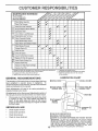
GENERAL
LUBRICATION
RECOMMENDATIONS
CHART
(_)
The warranty on this tractor does not cover items that have
been subjected to operator abuse or negligence.
To
receive full value from the warranty, operator must maintain
tractor as instructed in this manual
ZERK(_)
(_)
BEARING
Some adjustments will need to be made periodically to
properly maintain your tractor.
".FRONT WHEEL(_)
BEARING ZERK
ZERK
All adjustments in the Service and Adjustments section of
this manual should be checked at least once each season.
"
Once a year you should replace the spark plug, clean
or replace air filter, and check blades and belts for
wear. A new spark plug and clean air filter assure
proper air4uel mixture and help your engine run better
and last Ionger_
BEFORE
(_) ATTACHMENT
CLUTCH
PIVOT(S)
_
EACH USE
•
Check engine oil level
o
Check brake operation°
o
o
Check tire pressure.,
Check for loose fasteners,
PIVOTS
(_) SAE 30 OR 10W30 MOTOR OIL
(_) GENERAL PURPOSE
GREASE
(_) REFER TO CUSTOMER RESPONSIBILITIES
"ENGINE" SECTION
IMPORTANT:
DO NOT OIL OR GREASE THE PIVOT POINTS
WHICH HAVE SPECIAL NYLON BEARINGS
VISCOUS
LUBRICANTS WILL ATTRACT
DUST AND DIRT THAT WILL SHORTEN
THE LIFE OF THE SELF-LUBRICATING
BEARINGS.
IF YOU
FEEL THEY MUST BE LUBRICATED,
USE ONLY A DRY, Pew15
DERED
GRAPHITE
TYPE
LUBRICANT
SPARINGLY
CUSTOM
RESPONSIBIL
ES
TRACTOR
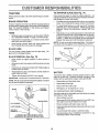
TO SHARPEN
Always observe safety rules when performing any maintenance.
Care should be taken to keep the blade balanced. An
unbalanced blade will cause excessive vibration and eventual damage to mower and engine.
BRAKE
=
The blade can be sharpened with a file or on a grinding
wheel° Do not attempt to sharpen while on the mower..
=
To check blade bafance, you will need a 5/8" diameter
steel bolt, pin, or a cone batancer, (When using a cone
batancer, follow the instructions supplied with batancer).
o
Slide blade on to an unth readed portion of the steel bolt
or pin and hold the bolt or pin parallel with the ground.
If blade is balanced, it should remain in a horizontal
position. If either end of the blade moves downward,
sharpen the heavy end until the blade is balanced°
OPERATION
If tractor requires more than six (6) feet stopping distance
at high speed in highest gear, then brake must be adjusted.
(See 'q'O ADJUST BRAKE" in the Service and Adjustments section of this manual)_
TIRES
o
Maintain proper air pressure in all tires (See "PRODUCT SPECIFICATIONS
on page 3 of this manual)°
o
Keep tires free of gasoline, oil, or insect control chemicals which can harm rubber°
,,
Avoid stumps, stones, deep ruts, sharp objects and
other' hazards that may cause tire damage.
BLADE
BLADE
(See Fig. 14)
NOTE: Do not use a nail for balancing blade.. The lobes of
the center hole may appear to be centered, but are not.
CARE
CENTER HOLE
/
/
For best results mower blades must be kept sharp° Replace bent or damaged blade&
BLADE
REMOVAL
(See Fig. 13)
=
Raise mower to highest position to allow access to
bladeso
o
Remove hex bolt, Iockwasher and flat washer securing
blade°
o
install new or resharpened blade with trailing edge up
towards deck as shown°
o
Reassemble hex bolt, lock washer and flat washer in
exact order' as shown°
FIG. 14
BATTERY
o Tighten bolt securely (30-35 Ft. Lbs. torque)°
IMPORTANT: BLADE BOLT IS GRADE 8 HEATTREATED.
Your tractor has a battery charging system which is sufficient for normal use,, However, periodic charging of the
battery with an automotive charger will extend its _ife.
NOTE: We do not recommend sharpening blade- but ifyou
do, be sure the blade is balanced.
o
Keep battery and terminals clean.
=
Keep battery botts tight°
•
o
Keep small vent holes open.
Recharge at 6-10 amperes for 1 hour.
BLADE
TO CLEAN BATTERY AND TERMINALS
Corrosion and dirt on the battery and terminals can cause
the battery to "leak" power..
°
I
Open battery box door.
Disconnect BLACK battery cable first then RED battery cable and remove battery from tractor.
TRAILING EDGE
FLA
LOCI{ WASHER .,,_
HEX BOLT
(GRADE 8)*
*A GRADE 8 HEAT TREATED BOLT CAN BE
IDENTIFIED BY SIX LINES ON THE BOLT HEAD,
FIG. 13
!6
°
Rinse the battery with plain water and dry.,
o
Clean terminals and battery cable ends with wire brush
until bright.
o
Coat terminals with grease or petroleum jelly°
.
Reinstall battery (See "CONNECT
Assembly section of this manual).
BATTERY" in the
.....
i
CUSTOMER
RESPON$ BmLmTUE$
V-BELTS
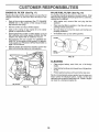
TO CHANGE ENGINE OIL (See Figs., !5 and 16)
Check V-belts for deterioration and wear after 100 hours of
operation and replace if necessary. The belts are not
adjustable. Replace belts if they begin to slip from wear_
Determine temperature range expected before oil change.
All oil must meet API service classification SF or SG
•
Be sure tractor is on level surface,
TRANSAXLE
o
Oil will drain more freely when warm.
Catch oil in a suitable container.
°
Remove oil fill cap/dipstick_ Be careful not to altow dirt
to enter the engine when changing oil,
o
Remove drain plug,,
o
After oi! has drained completely, replace oil drain plug
and tighten securely_
•
Refill engine with oil through oil fill dipstick tube. Pour
siowly. Do not overfill, For approximate capacity see
"PRODUCT SPECIFICATIONS"
on page 3 of this
manual
•
Use gauge on oil fi!l cap/dipstick for checking level.
Insert dipstick into the tube and rest the oil fill cap on the
tube. Do not thread the cap onto the tube when taking
reading° Keep oil at"FULL" line on dipstick Tighten
cap onto the tube securety when finished,
COOLING
Keep transaxle free from build-up of dirt and chaff which
can restrict cooling°
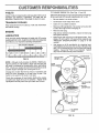
ENGINE
LUBRICATION
Only use high quality detergent oil rated with API service
classification SForSGo Select the oil's SAE viscosity grade
according to your expected operating temperature_
SAE VISCOSITY GRADES
I
°F
-20 °
°c -3oo
0"
30 °
-_0_
....... -_o_
TEMPERATURE
32"
40 _
o°
RANGE ANTICIPATED
60 °
1oo
L
80 _
20°
100"
soo
40°
BEFORE NEXT OIL CHANGE .........
AIR CLEANER
COVER
FIG, 15
NOTE: AIthough multi-viscosity oils (5W30, 10W30 etco)
improve starting in cold weather, these multi-viscosity oils
will result in increased oil consumption when used above
32°F. Check your engine oil level more frequently to avoid
possible engine damage from running low on oil
, WING NUT
FOAM
PRE-CLEANER
Change the oil after the first two hours of operation and
every 50 hours thereafter or at least once a year if the
tractor is not used for 50 hours in one year,
Check the crankcase oil level before starting the engine
and after each eight (8) hours of operation. Tighten oil fill
cap/dipstick securely each time you check the oil level.
PAPER CARTRIDGE
AIR CLEANER
BASE
FILL
CAP/DIPSTICK
AIR
SCREEN
OIL DRAIN
PLUG
FIG. 16
17
......
......................................................
= ,
CUSTOMER
CLEAN
AiR SCREEN
(See
=
.................
CLEAN AIR INTAKF.JCOOLiNG
Fig. 16)
AREAS
To insure proper cooling, make sure the grass screen,
cooling fins, and other external surfaces of the engine are
kept clean at al! times°
Every 100 hours of operation (more often under extremely
dusty, dirty conditions), remove the blower' housing and
other cooling shroud& Clean the cooling fins and external
surfaces as necessary. Make sure the cooling shrouds are
reinstaile&
(See Fig. 16)
Your engine will not run properly using a dirty air filter.
Clean the foam pre-cleaner after every 25 hours of operation or every season_ Service paper cartridge every 100
hours of operation or every season, whichever' occurs firsL
NOTE: Operating the engine with a blocked grass screen,
dirty or plugged cooling fins, and/or cooling shrouds removed will cause engine damage due to overheating_
Service air cleaner more often under dusty conditions.
o
_
RESPONSiBILITiES
Air screen must be kept free of dirt and chaff to prevent
engine damage from overheating. Clean with a wire brush
or compressed air to remove dirt and stubborn dried gum
fibers°
AIR FILTER
=,,,=,=
........................
Remove knob and cover'.
MUFFLER
o Remove wing nut and air cleaner from base..
TO SERVICE PRE-CLEANER
Inspect and replace corroded muffler and spark attester (if
equipped) as it could create a fire hazard and/or damage.
o
Slide foam pre-cleaner off cartridge.
o
Wash it in liquid detergent and water.
SPARK
o
Squeeze it dry in a clean cloth.
Replace spark plugs at the beginning of each mowing
season or after every 100 hours of operation, whichever
occurs first. Spark plug type and gap setting are shown in
"PRODUCT SPECIFICATIONS" on page 3 of this manual
o
Saturate it in engine oil Wrap it in clean, absorbent
cloth and squeeze to remove excess oil
TO SERVICE CARTRIDGE
o
Gently tap the flat side of the paper cartridge to dislodge dirt.. Do not wash the paper cartridge or use
pressurized air, as this will damage the cartridge.
Replace a dirty, bent, or damaged cartridge°
o
Reinstall the pre-cieaner (cleaned and oited) over the
paper cartridge=
o
Reassemble air cleaner, wing nut, cover and tighten
knob securely_
!8
PLUGS
ENGINE
OIL FILTER
(See Fig, 17)
IN-LINE
FUEL
FILTER
(See Fig. 18)
Replace the engine oil _ter every season or every other oil
change if the tractor is used more than !00 hours in one
year,.
The fuel filter should be replaced once each season.. If fuel
filter becomes clogged, obstructing fuel flow to carburetor,
replacement is required.
o
Drain oil from engine crankcase (See "TO CHANGE
ENGINE OIL" in this section of this manual, through
step remove drain plug).
=
With engine cool, remove filter and plug fuel line
sections..
o
o
Remove oil filter and wipe off filter adapter,1
Place new fuel filter in position in fuel line with arrow
pointing towards carburetor°
=
Apply a thin coating of new engine oil to the rubber
gasket on replacement oil fiiter..
°
Be sure there are no fuel line leaks and clamps are
properly positioned_
°
Install replacement oil filter on filter adapter. Turn oil
filter clockwise until rubber gasket contacts the filter
adapter, then tighten filter an additional t/2 turn.
°
tmmediatelywipe
=
Fill crankcase with new oil (See "TO CHANGE ENGINE OIL" in this section of this manual), For approximate capacity see "PRODUCT SPECIFICATIONS" on
page 3 of this manual.
°
Start the engine and check for oil leaks_ Correct any
leaks before placfng engine into full operation..
up any spilled gasoline.
CLAMP
FUEL
FILTER
I
FIG. 18
CLEANING
•
Clean engine, battery, seat, finish, etc. of all foreign
matter.
o
Keep finished surfaces and wheels free of all gasoline,
oil, etco
=
Protect painted surfaces with automotive type wax°
We do not recommend using a garden hose to clean your
tractor unless the electrical system, muffler, air filter and
carburetor are covered to keep water out. Water in engine
can resutt in a shortened engine life_
OIL FILTER
FIG, 17
'19
..... i, ,........
iii
..............
i
SERVHCE AN
ADJUSTMENTS
i,
ii1,,,,,,,i,1,,,
CAUTION:
o
o
o
o
o
,,,11,1
Depress clutch/brake pedal fully and set parking brake.
Place gearshift lever in neutral (N) position.
Place attachment clutch in "DISENGAGED" position,
Turn ignition key "OFF" and remove key°
Make sure the blades and all moving parts have completely stopped.
Disconnect spark plug wire from spark plug and place wire where it cannot come in contact with
plug.
i, i,
,,i,,
.............
TRACTOR
MOWER
(See Fig. 19)
Mower will be easier to remove from the right side of tractor.
o
=
Piace attachment clutch in "DISENGAGED" position_
Move attachment lift lever forward to lower mower to its
lowest position_
°
Roll belt off engine pulley.
o
Disconnect clutch rod from clutch lever by removing
reta!ner spring.,
=
Disconnect anti-sway bar from chassis bracket by
removing retainer spnngo
=
Disconnect suspension arms from rear deck brackets
by removing retainer springs,,
°
Disconnect front links from deck by removing retainer'
springs.
.
Raise lift lever to raise suspension arms. Slide mower
out from under tractor.
IMPORTANT:
tF AN ATTACHMENT OTHER THAN THE
MOWER IS TO BE MOUNTED TO THE TRACTOR,
REMOVE THE FRONT LINKS.
TO iNSTALL
, i,r
BEFORE PERFORMING ANY SERVICE OR ADJUSTMENTS:
..... i1,11111
TO REMOVE
ii i,i1,,,,i,,,,i,i,
iVIOWER (See Fig. 19)
=
Raise attachment lift lever to its highest position.
°
Slide mower under tractor with discharge guard to right
side of tractor.
,,
.
Lower lift lever' to its lowest position=
Install mower in reverse order of removal instructions.
CLUTCH
SUSPENSION
RETAINER
;PRING
qTI-SWAY BAR
RETAINER
SPRINGS
(BOTH SIDES)
FIG. 19
SERVICE AN
, i,,i,,11,i,1,1,1
..........
ADJUSTMENTS
_,,i,,
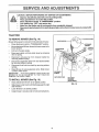
TO LEVEL MOWER HOUSING
,,
FRONT-TO-BACK ADJUSTMENT (See Figs° 22 and 23)
IMPORTANT: DECK MUST BE LEVEL SIDE-TO-SIDE. fF
THE FOLLOWING FRONT-TO-BACK ADJUSTMENT IS
NECESSARY, BE SURE TO ADJUST BOTH FRONT LINKS
EQUALLY SO MOWER WILL STAY LEVEL SIDE-TOSIDE,
Adjust the mower while tractor is parked on level ground or
driveway°
Make sure tires are properly inflated (See
"PRODUCT SPECIFICATIONS" on page 3 of this manual).
If tires are over or underinflated, you will not properly adjust
your mower.
NOTE: Each full turn of adjustment nut will change mower
height about 1/8"..
To obtain the best cutting results, the mower housing
should be adjusted so that the front is approximately I/4" to
3/4" lower than the rear when the mower is in its highest
position,
Check adjustment on right side of tractor.. Measure distance "D" directly in front and behind the mandrel at bottom
edge of mower housing as shown
•
Before making any necessary adjustments, check that
both front links are equal in length.. Both links should be
approximately t0-3/8"o
o If links are not equal in length, adjust one link to same
length as other link.
To lower front of mower loosen nut "E" on both front
links an equal number of turns,
°
When distanc& "D" is 1/4" to 3/4" lower at front than
rear, tighten nuts "F" against trunnion on both frc;_t
links,
o
o
SIDE-TO-SIDE ADJUSTMENT
(See Figs. 20 and 21)
o
Raise mower to its highest position..
•
At the midpoint of both sides of mower, measure height
from bottom edge of mower to groundo Distance"A" on
both sides of mower should be the same or within 1/4"
of each other.
o
If adjustment is necessary, make adjustment on one
side of mower onlyo
o
To raise one side of mower, tighten lift link adjustment
nut on that side..
o
To lower one side of mower, loosen lift link adjustment
nut on that side.
Recheck measurements
after adjusting,
BOTTOM EDGE
OF MOWER TO
GROUND
BOTTOM EDGE
OF MOWER TO
GROUND
o
-
To raise front of mower, loosen nut"F" from trunnion on
both front links° Tighten nut "E" on both front links an
equal number of turns°
When distance "D" is 1/4" to 3/4" lower at front than
rear, tighten nut"F" against trunnion on both front links..
Recheck side-to_side adjustment..
_3;_ %
GROUND
LINE
I
MANDREL
A
FIG. 20
SUSPENSION
ARM
FIG. 22
BOTH FRONT LINKS MUST BE EQUAL IN LENGTH
LIFT LINK
ADJUSTMENT NUT
FIG. 21
NUT "E"
NUT "F"
FRONT LINKS
21
TRUNNION
FIG. 23
SERVUOE AN
L
'
ADJUSTMENTS
i ........
i
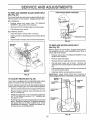
TO REPLACE
(See Fig, 24)
MOWER
BLADE
DRIVE
WITH PARKING BRAKE "ENGAGED"
BELT
The mower blade drive belt may be replaced without tools,
Park the tractor on level surface, Engage parking brake°
BELT REMOVAL o
Remove mower from tractor (See "TO REMOVE
MOWER" in this section of this manual),
=
Work belt off both mandrel pulleys and idler pulleys.
o
Pul! belt away from mower,
BELT INSTALLATION
-
o
install new belt in reverse order of removal,
=
Make sure bett is in all pulley grooves and inside all belt
guides,,
Install mower in reverse order of removal instructions.
o
FIG. 25
MANDREL
PULLEY
IDLER
PULLEYS
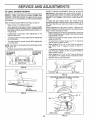
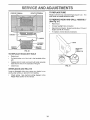
TO REPLACE
(See Fig. 26)
MOTION
DRIVE
BELT
Park the tractor on level surface, Engage parking brake.
For assistance, there is a belt installation guide decal on
bottom side of left footresL
MANDREL
PULLEY
BRAKE
(See
Remove mower (See "TO REMOVE MOWER" in this
section of this manuaL)
o
Remove upper belt keepeL
=
=
Remove belt from stationary idler and clutching idler,
Pull be_t slack toward re,_r of tractor, Remove belt
upwards from transaxle pulley by deflecting belt keepers,
.
Pull belt toward front of tractor and remove
from around engine pu_[eyo
downwards
= install new belt by reversing above procedure,
IMPORTANT:
MAKE SURE UPPER BELT KEEPER iS
POSITIONED PROPERLY BETWEEN LOCATOR TABS.
FIG. 24
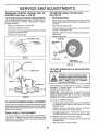
TO ADJUST
o
Fig. 25)
Your tractor' is equipped with an adjustable brake system
which is mounted on the right side of the transaxle.
EN GINE"-'._
PULLEY
_Tu
ABS
tf tractor requires more than six (6) feet stopping distance
at high speed in highest gear, then brake must be adjusted,
o
Depress clutch/brake pedal and engage parking brake,
,,
Measule distance between brake operating arm and
nut "A" on brake rod°
o
If distance is other than 1-1/2", loosen jam nut and turn
nut "A" until distance becomes 1-1/2". Retighten jam
nut against nut "A",
o
Road test tractor for proper stopping distance as stated
above., Readjust if necessary. If stopping distance is
still greater than six (6) feet in highest g_ar, further
maintenance is necessary. Contact your nearest authorized service center/department.
LOCATOR
CLUTCHING
IDLER
STATIONARY
IDLER
PULLEY
FIG. 26
i ....
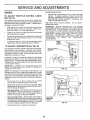
TRANSAXLE
SHIFTER
LINKAGE
JUSTMENT (See Figs. 27 and 28)
AND
TO REMOVE WHEEL
(See Fig. 29)
AD-
i
,i
FOR REPAIRS
The transaxle should be in neutral when the gear shift Iever
is in the neutraf (N) (lock gate) position. The adjustment is
preset at the factory; however, if adjustment is needed,
proceed as follows:
o
Block up axle securely.
o
Remove axle cover, retaining ring and washers to allow
wheel removal (rear wheef contains a square key - Do
not lose)o
°
Make sure transax}e is in neutrat (N),.
o
Repair tire and reassemble..
°
Loosen two Iocknuts on tie rod°
°
•
Turn center rod until gearshift lever falls into neutral
lock g_te on fender console.
On rear wheels only: align grooves in rear wheel hub
and axle. Insert square key_
.
,,
Tighten Iocknuts securely.
Replace washers and snap retaining ring securely in
axle groove.
=
Replace axle cover°
WASHERS
GEARSHIFTLEVER
RETAINING
RING
NEUTRAL
LOCK GATE
I
FIG. 27
AXLE COVER
SQUARE KEY
(REAR WHEEL ONLY}
FIG, 29
_._......_4_00
KNLIT S
TO START ENGINE WEH
(See Fig. 30)
.....
__c.oo
T,,
ooo
------4
A WEAK
BATTERY
)
If your battery is too weak to start the engine, it should be
recharged°
If "jumper cables" are used for emergency
starting, follow this procedure:
IMPORTANT:
YOUR TRACTOR
IS EQUIPPED WtTHA
12 VOLT NEGATIVE GROUNDED
SYSTEM. THE OTHER
VEHICLE
MUST
ALSO
BE A 12 VOLT
NEGATIVE
GROUNDED
SYSTEM.
DO NOT USE YOUR TRACTOR
BATTERY TO START OTHER VEHICLES
FIG. 28
TO ATTACH JUMPER CABLES -
TO ADJUST
STEERING
WHEEL ALIGNMENT
,
If steering wheel crossbars are not horizontal (left to right)
when wheels are positioned straight forward, remove steer s
ingwheel and reassemble per instructions in the Assembly
section of this manual.
FRONT WHEEL
°
=
TOE-IN/CAMBER
The front wheel toe-in and camber are not adjustable on
your tractor_ If damage has occurred to affect the front
wheel toe-in or camber, contact your nearest authorized
service center/department_
Connect each end of the RED cable to the POSITIVE
(+) terminal of each battery, taking care not to short
against chassis_
Connect one end of the BLACK cable to the NEGATIVE (-) terminal of fully charged battery.
Connect the other end of the BLACK cable to good
CHASSIS GROUND, away from fuel tank and battery.
TO REMOVE CABLES, REVERSE ORDER ,
BLACK cable first from chassis and then from the fully
charged battery°
= RED cable last from both batteries°
23
AND ADJUSTMENTS
POSITIVE TERMINAL
TO REPLACE
NEGATIVE TERMINAL
FUSE
Replace with 30 amp automotive-type plug-in fuse
fuse holder is located behind the dash..
TO REMOVE HOOD
(See Fig. 31)
AND GRILL
ASSEMBLY
•
Raise hood.
•
Unsnap headlight wire connector.
o
Stand in front of tractoro Grasp hood at sides, tilt toward
engine and lift off of tractor.
o
To replace, reverse above procedures..
CABLES
HOOD
CHARGED
BATTERY
POSITIVE
TERMINAL
NEGATIVE
TERMINAL
HEADLIGHT
_IRE
CONNECTOR
FIG. 30
TO REPLACE
HEADLIGHT
BULB
o
Raise hood..
o
Pull bulb holder out of the hole in the backside of the
grill.
•
Replace bulb in holder and push bulb holder securely
back into the hole in the backside of the grill.
Close hood..
o
mNTERLOCKS
FIG. 31
AND RELAYS
Loose or damaged wiring may cause your tractor to run
poorly, stop running, o_ prevent it from starting.
°
Check wiring.. See electrical wiring diagram in the
Repair Parts section of this manual
24
The
SERVnCE AN
ADJUSTMENTS
ENGINE
ACCELERATION
TO ADJUST THROTTLE
(See Fig. 32)
CONTROL
-
CABLE
The throttle control has been preset at the factory and
adjustment should not be necessary° Check adjustmentas
described below before loosening cable_ If adjustment is
necessary, proceed as follows:
,,
With engine not running, move throttle control lever
from slow [_) to choke (t'-.!) position. Slowly move
lever from choke (N) to fast (,_,) position.
-
Check to see if hole in throttle lever and hole in speed
control bracket are aligned.
o
If holes are not aligned, loosen cable clamp screw and
align the holes by inserting a pencil or a 1/4" drill bit
through both holes.,
•
Pull throttle cable up to remove slack and tighten cable
clamp screw. Remove alignment pencil or drilt bit..
TO ADJUST
CARBURETOR
TEST
-
Move throttle control lever from slow (-_) to fast
position,
If engine hesitates
or dies, turn idle
adjusting needle out (counterclockwise)
1/8 turn.
peat test and continue to adjust, if necessary,
engine accelerates
smoothly..
Nigh speed stop is factory
damage may result.
adjusted°
CABLE
CLAMP
SCREW,
SPEED
BRACKET
In general, turning the adjusting needles in (clockwise)
decreases the supply of fuel to the engine giving a leaner
fuel/air mixture. Turning the adjusting needles out (counterclockwise) increases the supply of fuel to the engine giving
a richer fuel/air mixture..
THROTTLE
LEVER
IMPORTANT:
DAMAGE TO THE NEEDLES AND THE
SEATS tN CARBURETOR MAY RESULT IF NEEDLE iS
TURNED IN TOO TIGHT..
FIG, 32
NOTE: The carburetor on this engine is low emission_ it is
equipped with an idle fuel adjusting needle with a ]imiter
cap, which allows some adjustment within the Iimits allowed
by the cap. Do not attempt to remove the timiter cap. The
timitercap cannot be removed without breaking the adjusting
needle.
Be sure you have a clean air filter and the throttle
control cable is adjusted properly (see above).
-
Start engine and allowto warm for five minutes. Make
adjustments with engine running and shift!motion control
lever in neutral (N) position.
°
idle speed setting - With throttle control lever in slow
(,_)
position, engine should idle at 1750 RPM. If
engine idles too slow or fast, turr_ idle speed adjusting
screw in or out until correct idle is attained_
o
Idle fuei needle settincl - With throttle control lever in
slow (,_) position, turn idle fuel adjustment needle in
(clockwise) untif engine begins to die and then turn out
(counterclocI_vise) until engine runs rough. Turn needle
to a point midway between those two positions.
-
IMPORTANT:
NEVER TAMPER
WITH THE ENGINE
GOVERNOR,
WHICH IS FACTORY
SET FOR PROPER
ENGINE SPEED
OVERSPEEDINGTHEENGINEABOVE
THE
FACTORY
HIGH
SPEED
SETTING
CAN BE
DANGEROUS..
IF YOU THINK THE ENGINE-GOVERNED
HtGH SPEED NEEDS ADJUSTING,
CONTACT
YOUR
NEAREST
AUTHORIZED
SERVICE
CENTER/
DEPARTMENT,
WHICH HAS PROPER EQUIPMENT
AND
EXPERIENCE
TO
MAKE
ANY
NECESSARY
ADJUSTMENTS.
The carburetor has been preset at the factory and adjustment should not be necessary. However, minor adjustmerit may be required to compensate for differences in fuel,
temperature, altitude or toad. if the carburetor does need
adjustment, proceed as follows:
=
Do not adjust
(See Fig, 33)
-
(,_)
fuel
Reuntil
IDLE SPEED
ADJUSTING
IDLE
FUEL /
iADJUSTING
!NEEDLE
FIG. 33
Recheck idle speed. Readjust if necessary.
25
,,vJL
.......
u,,,,,u,,,,,,,,u ....
i,Ul, ,i .....
i,
STORAGE
Immediately prepare your tractor for storage at the end of
the season or if the tractor wil! not be used for 30 days or'
more_
CAUTION: Never store the tractor with
gasoline in the tank inside a building
where fumes may reach an open flame
or spark.
Allow the engine to cool
before storing in any enclosure.
TRACTOR
Remove mower from tractor for winter' storage_ When
mower is to be stored for a period of time, ciean it thoroughly, remove all dirt, grease, leaves, etc, Store in a
clean, dry area,,
o
Clean entire tractor (See"CLEANING"in the Customer
Responsibilities section of this manual)°
=
Inspect and replace belts, if necessary (See belt replacement instructions in the Service and Adjustments
section of this manual),
°
Lubricate as shown in the Customer Responsibilities
section of this manual
o
Be sure that all nuts, bolts and screws are securety
fastened Inspect moving parts for damage, breakage
and wear,, Replace if necessary°
°
Touch up all rusted or chipped paint surfaces; sand
lightly before painting,
BATTERY
.
Fully charge the battery for storage°
°
After a period of time in storage, battery may require
recharging°
.
To help prevent corrosion and power leakage during
long periods of storage, battery cables should be
disconnected and battery cleaned tho roughly (see'q'O
CLEAN BATTERY AND TERMINALS" in the Customer Responsibilities section of this manual).
°
After cleaning, leave cables disconnected and place
cables where they cannot come in contact with battery
terminals.
ENGINE
FUEL SYSTEM
IMPORTANT:
IT IS IMPORTANT
TO PREVENT
GUM
DEPOSITS
FROM FORMING
IN ESSENTIAL
FUEL
SYSTEM PARTS SUCH AS CARBURETOR,
FUEL FILTER,
FUEL HOSE, OR TANK DURING
STORAGE,
ALSO,
EXPERIENCE
INDICATES
THAT ALCOHOL
BLENDED
FUELS (CALLED
GASOHOL
OR USING ETHANOL
OR
METHANOL)
CAN ATTRACT MOISTURE WHICH LEADS
TO SEPARATION
AND FORMATION
OF ACIDS DURING
STORAGE.
ACIDIC GAS CAN DAMAGE
THE FUEL
SYSTEM OF AN ENGINE WHILE IN STORAGE.
o
Drain the fuel tank.
=
Start the engine and let it run until the fuel lines and
carburetor are empty..
o
Never use engine or carburetor' cleaner products in the
fuel tank or permanent damage may occur..
Use fresh fuel next season..
o
NOTE: Fuel stabilizer is an acceptable alternative in
minimizing the formation of fuel gum deposits during stop
age. Add stabilizer to gasoline in fuel tank or' storage
container° Always follow the mix ratio found on stabilizer
container. Run engine at least 10 minutes after adding
stabilizer to allow the stabilizer to reach the carburetor'. Do
not drain the gas tank and carburetor if using fuel stabilizer.
ENGINE
OIL
Drain oil (with engine warm) and replace with clean engine
oil. (See "ENGINE" in the Customer Responsibilities
section of this manual).
CYLINDERS
°
Remove spark plug(s)_
°
Pour one ounce of oil through spark plug hole(s) into
cylinder(s).
o
Turn ignition key to"START" position for a few seconds
to distribute oil.
-
Replace with new spark plug(s).
OTHER
o
Be sure battery drain tube is securely attached.
.
Do not store gasoline from one season to another°
o
If battery is removed from tractor for storage, do not
store battery directly on concrete or damp surfaces.
o
Replace your gasoline can if your can starts to rust°
Rust and/or dirt in your gasoline will cause problems°
o
If possible, store your tractor indoors and cover it to
give protection from dust and dirt°
o
Cover your tractor with a suitable protective cover that
does not retain moisture. Do not use plas_, '.. Plastic
cannot breathe which allows condensation to f "rm and
wilt cause your tractor to rusL
IMPORTANT: NEVER COVER TRACTOR WHILE EN _INE
AND EXHAUST AREAS ARE STILL WARM
TROUBLESHOOTBNG
,11
I
....
ii,l,,l
.....
i1,,,,i.
,
_
POINTS
..............................................
i
PROBLEM
CAUSE
CORRECTION
Wig not start
1
2
3
4
5
6.
7
Out of fuel.
Engine not "CHOKED" properfy.
Engine floode&
Bad sparkplug
Dirty air filter.
Dirty fuel filter
Water in fuel.
1..
Fill fuel tank
2.
3
4
5.
6
7
See "-rO START ENGINE" in Operation section
Wait several minutes before attempting to start
Replace spark plug.
Clean/replace air filter
Replace fuel filter.
Drain fuel tank and carburetor, refill tank with fresh
8
9..
10
Loose or damaged wiring
Carburetor out of adjustment..
Engine valves out of adjustment
8
9
10
1.
2
3
4
5
6.
7
8o
Clean/replace air filter
Replace spark plug
Recharge or replace battery
Replace fuel filter
Drain fuei tank and relill with fresh gasoline.
Check a_lwiring
Contact an authorized service center/department
Contact an authorized service center/department
Corroded battery terminals
Loose or damaged wiring
Faulty ignition switch..
Faulty solenoid or starter
Faulty operator presence switch(es).
l.
2
3
4
5
6
7,
8
9
Depressclutchibrake
pedal
Disengage attachment clutch
Recharge or replace battery.
Replace fuse,
Clean battery terminals
Check all wiring
Check/replace ignition switch
Check/replace solenoid or starter
Contact an authorized service center/department
1
2
3.
4.
Weak or dead battery..
Corroded battery terminals.
Loose or damaged wiring
Faulty solenoid or starter.
1
2
3.
4_
Recharge or replace battery
CIean battery terminals.
Check all wiring.
Check!replace solenoid or starter.
1-_
2
3
4
5.
6..
7.
8
9
Cutting too much grassttoo fast
Throttle in "CHOKE" positiOn.r
Build-up of grass, ieaves and trash under mower.
Dirty air rifler..
Low oil level/dirty oil
Faulty spark plug
Dirty fuel filter.
State or dirty fuel
Water in fuel
1
2
3
4
5.
6.
7
8
9
Set in "Higher Cut" position/reduce
speed.
Adjust throttie control
Clean underside of mower housing
Clean/replace air filter
Check oil level/change oil.
Clean and regap or change spark plug
Replace fuel filter
Drain fuel tank and refill with fresh gasoline.
Drain fuel tank and carburetor, refill tank with fresh
gasoline and reptace rue! filter.
Connect and tighten spark plug wire
Clean engine air screen!fins
Clean/replace muffler
Check all wiring
Contact an authorized service center/department
Contact an authorized service center/department
1
2
3.
Dirty air filter.
Bad spark plug
Weak or dead battery
4.
5
6
7
8
Dirty fuel filter
Stale or dirty fuel
Loose or damaged wiring.
Carburetor out of adjustment
Engine vaives out of adjustment
I..
2
3
4
Clutch/brake pedal not depressed
Attachment clutch is engaged
Weak or dead battery
Blown fuse
5.
6.
7.
8
9
Engine clicks but will not
start
Loss of power
=
gasoline and replace fuel _ter
Check altwiring
Contact an authorized service center/department
Contact an authorized service center/department
nn, m,n,,,=
Engine will not turn over
10_
11
12
13,
14_
15-
t0
t I.
12.
13
14.
15
Spark plug wire loose
Dirty engine air screen/fins.
Dirtytclogged muffler.
Loose or damaged wiring
Carburetor out of adjustment
Engine valves out of adjustment,
..............................
Excessive vibration
1
2
Worn. bent or loose blade
Bent blade mandrel
3..
Loose/damaged
1.
2.
3
part(s).
27
=ll
i,,u
Replace blade Tighten blade boil
Replace blade mandrel
Tighten loose part(s)
Replace damaged
parts
TROUBLESHOOTSNG
=
PROBLEM
..................
CAUSE
L
POINTS
................
CORRECTION
L I_
Engine continues to run
when operator leaves seat
with attachment clutch
i
1
Faulty operator-safety
presence control system,
1,
i
..................
Checkwiring, switches and connect}OnSr tf not
corrected, contact an authorized service center/
department
engaged
Poor cut - uneven
.....
==!=!
-=H
,,=
Worn, bent or loose blade
Mower deck not level
Buildup of grass, leaves, and trash under mower.
Bent blade mandrel,
S
Clogged mower deck vent holes from buildup of
grass, leaves, and trash around mandrels
1
2
Replace blade, Tighten blade bolt
Level mower deck.
3
4
5
Clean underside of mower housing
Replace blade mandrel
Clean around mandrels to open vent holes
1,
2.
3
4.
Remove
Replace
Replace
Replace
,-i
Mower blades will not
rotate
....
1
2.
3
4
1
Obstruction in dutch mechanism
2,
3,
4,
Worn!damaged mower drive belt
Frozen idler pulley
Frozen blade mandrel
1
2
3
4.
5
6
Engine speed too slow
Travel speed too fast
Wet grass
Mower deck not level
Low/uneven tire air pressure
Worn, bent or loose blade.
7
8
Buildup of grass, leaves and trash under mower
Mower drive bellworn
9,,
10
11,
Blades improperly installed
Improper blades used,
Clogged mower deck vent holes from buildup of
grass, leaves, and trash around mandrels
obstruction
mower drive beff
idler pulley
blade mandrel,
,, ,,,,,,,, ,, ,,
Poor' grass discharge
Headlight{s) not working
(if so equipped)
1
2
3
4
5
6,,
7,,
8
9
t0,
11.
Place throttle control in "FAST" position
Shiftto s!ower speed.
Atlow grass to dry before mowing
Level mower decJ(.
Checktires for proper air pressure,
Replace/sharpen blade Tighten blade bolt,
Clean underside of mower housing.
Replace mower drive belt
Reinstall blades sharp edge down
Replace with blades listed in this manual
Clean around mandrels to open vent holes
1.
Switch is "OFF"
1.
Turn switch "ON"
2.
3
4
5
Bulb(s) burned out
Faulty light switch
Loose or damaged widng
Blown fuse,
2.
3
4
5
Replace bulb(s),
Checldrep_ace light switch.
Check wiring and connections
Replace fuse.
1
2
3.
4
Bad battery cell(s)
Poor cable connections
Faulty regulator (if so equipped).
Faulty alternator.
1.
2.
Replace battery
Check/dean aH connections
3.
4.
Replace regulator,
Replace alternator.
1,,
Engine throttle centre! not set at "SLOW"
position for 30 seconds before stopping engine
1
Move throttIe control to "SLOW" position and allow
to idle for 30 seconds before stopping engine,
=, =,= "HH='
Battery will not charge
Engine "back-fires"
when turning engine
"OFF"