1
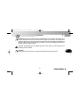
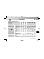
OM_F4 FT_USA_Ed.1.qxd
1-09-2010
16:09
Pagina 1
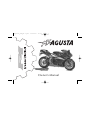
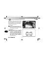
Owner’s Manual
OM_F4 FT_USA_Ed.1.qxd
1-09-2010
16:09
Pagina 2
California 65 Proposition Warning:
WARNING
This vehicle contains or emits chemicals known to the State of California to cause cancer and
birth defects or other reproductive harm.
Information
MV Agusta is committed to a policy of constant improvement; therefore, you may find slight differences between the information provided in this document and the vehicle you purchased. MV Agusta
reserves the right, in its sole discretion, to make changes to the motorcycle or this manual at any time
and without prior notice. Any supplement to this manual can be downloaded free of charge from our
website. Go to www.mvagusta.it .
Respect and defend natural environment
Everything we do affects the whole planet as well as its resources.
MV Agusta, in order to protect the interests of the community, alerts the Customers and the Technical
Assistance operators to use the vehicle and dispose of its replaced parts respecting the laws in force
concerning environmental pollution and waste disposal and recycling.
© 2010
This document may not, in whole or in part, be reproduced without prior consent, in writing, from MV Agusta S.p.A.
Part No. 8000B5372 - Edition No. 1
Printed in September 2010
-2-
OM_F4 FT_USA_Ed.1.qxd
1-09-2010
16:09
Pagina 3
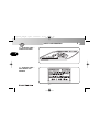
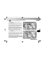
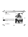
Rivolto, September 11th - 12th, 2010
Admiration, wonder and respect: these are the common feelings always aroused by the aircrafts and the
pilots of the Italian Acrobatic Team since the date of its birth.
The “Frecce Tricolori” represent a united team of pilots of the Military Air Force, which has been able to
proudly support the Italian national colors in the world throughout its whole history by linking them to
the highest values of quality, performance, style and professionalism.
These results can only come from a methodical and constant engagement, aimed to the unceasing
research of perfection in any action. MV Agusta shares, in its history, in its brand and in its people, the
same inspiring principles of the legendary “Frecce Tricolori”, as well as the awareness of being an icon
of the Italian style in the world.
In order to affirm the common engagement in pursuing excellence in any of its aspects, while celebrating the 50th Anniversary of the Acrobatic Team, MV Agusta has clothed the most powerful and fascinating of its creations with the colors of the Italian flag and sky, thus realizing an exclusive series of F4
bikes with the “Frecce Tricolori” livery.
The above motorcycles, prepared with special components and exactly numbered as the aircrafts of the
acrobatic team, recall their distinctive features and bear a silver plate reporting the number and the code
of the corresponding aeroplane.
The indications contained in the manual will help you make the most of your motorcycle in terms of both performance and operating life. The manual provides useful information on how to take care of your vehicle, and
also describes some routine maintenance operations. Fundamental units such as the engine and the transmission are covered in the Workshop Manuals. Operations involving these parts require specific equipment and
are reserved for skilled personnel. Your dealer possesses the skills, the equipment and the spare parts that are
needed to keep your motorcycle in optimum working order. This manual is to be considered as an integral part
of the vehicle, and must be transferred to any new owner together with the vehicle.
I wish to finally thank you for the trust you kindly gave us and send you my personal congratulations for
your new MV Agusta F4 1000 “Frecce Tricolori”.
MV Agusta
Claudio Castiglioni
President
-3-
OM_F4 FT_USA_Ed.1.qxd
1-09-2010
16:09
Pagina 4
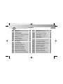
CONTENTS
chap. Subjects covered
1
1.1
1.2
1.3
1.4
1.5
2
2.1
2.1.1
2.1.2
2.1.3
2.1.4
2.1.5
2.1.6
2.1.7
2.1.8
2.1.9
2.1.10
2.1.11
2.1.12
2.1.13
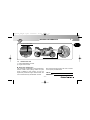
GENERAL INFORMATION
Purpose of this manual
General safety information
Symbols
Warranty Booklet and Service Coupons
Identification data
SAFETY INFORMATION
Safety
How to report a safety-related defect
Noise emission warranty
Note on tampering
Information on the emission control system
Safe riding
Maintaining your motorcycle
Before you ride
While you ride
After you ride
Installing accessories
Vehicle load
Modifications
Competitions
page
chap. Subjects covered
10
10
10
11
12
13
16
16
16
16
16
18
19
21
22
23
26
27
28
30
30
2.1.14
2.2
2.3
3
3.1
3.2
3.3
3.4
3.5
3.6
3.7
3.7.1
3.7.2
4
4.1
4.2
4.3
4.4
4.4.1
4.4.2
4.4.3
-4-
Suggestions against theft
Safety labels - Location
Safety - Visual and acoustic signals
CONTROLS AND INSTRUMENTS
Location of controls and instruments
Kickstand
Handlebar controls, left side
Handlebar controls, right side
Ignition switch and steering lock
Gear lever
Instruments and warning lights
Warning lights
Multifunction display
OPERATION
Using the motorcycle
Break-in
Starting the engine
Selecting and setting the display functions
Selecting the display functions
Trip reset
TC Mode
page
31
32
41
42
42
43
44
46
49
51
52
53
54
55
55
56
58
61
62
66
68
OM_F4 FT_USA_Ed.1.qxd
1-09-2010
16:09
Pagina 5
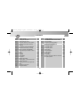
CONTENTS
chap. Subjects covered
page
chap. Subjects covered
page
4.4.4
Chronometer
69
5.8
Adjusting the rear suspension
101
4.4.5
NIGHT/DAY Mode
78
5.8.1
Rebound damper (rear suspension)
102
4.4.6
IMMOBILIZER Mode
79
5.8.2
4.4.7
How to select the mapping of the control unit
High speed compression damper
(rear suspension)
Low speed compression damper
(rear suspension)
Headlight adjustment
MAINTENANCE
Tables of scheduled maintenance and checks
Tools and accessories supplied
Table of lubricants and fluids
Removing/fitting the right-hand side fairing
Checking the engine oil level
Topping up the engine oil level
Checking the coolant level
Topping up the coolant level
Checking the wear of the brake pads
Checking the brake fluid level
Checking the clutch fluid level
Checking and replacing the tires
Checking and lubricating the drive chain
82
4.4.8. Warning/malfunction alerts
83
4.5
Refuelling
86
4.6
Glove compartment
88
4.7
Parking the motorcycle
89
4.8
Checks to be performed before riding
91
5
ADJUSTMENTS
93
5.1
List of adjustments
93
5.2
Table of adjustments
95
5.3
Adjusting the front brake lever
96
5.4
Adjusting the clutch lever
96
5.5
Adjusting the rearview mirrors
97
5.6
Adjusting the steering damper
97
5.7
Adjusting the front suspension
98
5.7.1
Spring preload (front suspension)
99
5.7.2
Rebound damper (front suspension)
99
5.7.3
Compression damper (front suspension)
100
5.8.3
5.9
6
6.1
6.2
6.3
6.4
6.5
6.5.1
6.6
6.6.1
6.7
6.8
6.9
6.10
6.11
-5-
103
103
104
106
106
116
117
118
120
121
123
124
126
127
129
130
135
OM_F4 FT_USA_Ed.1.qxd
1-09-2010
16:09
Pagina 6
CONTENTS
chap. Subjects covered
page
chap. Subjects covered
page
6.12
6.13
6.14
6.15
139
140
141
7
7.1
7.2
TROUBLESHOOTING FLOW CHART
Engine problems
Electrical equipment problems
160
160
165
8
8.1
8.1.1
8.1.2
8.1.3
8.1.4
8.1.5
8.1.6
8.2
8.3
TECHNICAL INFORMATION
Motorcycle overview
Front brake system
Rear brake system
Clutch system
Engine lubrication
Coolant system
Fuel system
Specifications
Measure equivalence tables for American
and metric systems
168
168
170
171
172
173
174
175
176
Checking the idle speed
Periodic emission check
Evaporative emission control system
Emission control system warranty
obligations
6.15.1 Your warranty rights and obligations
6.15.2 Manufacturer’s warranty coverage
6.15.3 Owner’s warranty responsibilities
6.16 Limited warranty on emission control
6.16.1
6.16.2
6.16.3
6.16.4
6.16.5
6.17
6.17.1
6.17.2
6.18
6.19
6.20
system
Coverage
Limitations
Limited liability
Legal rights
Additional information
Replacing parts - General information
Replacing the fuses
Replacing the license plate light bulb
Battery
Cleaning the motorcycle
Prolonged inactivity
142
142
142
143
144
144
145
146
147
147
148
148
152
155
157
159
-6-
183
OM_F4 FT_USA_Ed.1.qxd
1-09-2010
16:09
Pagina 7
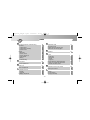
INDEX
A
C
Accessories
– installation
Adjustments
– clutch lever
– front brake lever
– front suspension
– headlight
– rear suspension
– rearview mirrors
– steering damper
– table
96
96
98
104
101
97
97
95
Battery
155
Brakes – fluid level, check
127
– front brake lever, adjustment
96
– front brake system
170
– pads, wear check
126
– rear brake system
171
Break-in
56
Chain
– check
– lubrication
Chronometer
Cleaning the motorcycle
Clutch
– fluid level, check
– lever, adjustment
– system
Competitions
Controls and instruments, location
Coolant
– level, check
– system
– topping up
27
B
129
96
172
30
42
123
174
124
D
Damper
– compression (front suspension)
– compression (rear suspension)
– rebound (front suspension)
– rebound (rear suspension)
Display
– multifunction
– selecting and setting functions
Bulbs, replacement of
– license plate light
135
137
69
157
152
-7-
100
103
99
102
54
61
OM_F4 FT_USA_Ed.1.qxd
1-09-2010
16:09
Pagina 8
INDEX
E
I
Electrical equipment, troubleshooting
Emissions
– control system
– control system warranty
– periodic check
Engine
– lubrication
– oil level, check
– oil level, topping up
– serial number
– starting
– troubleshooting
165
Fuel system
Fuses, replacement
175
148
Gear lever
Glove compartment
51
88
Handlebar controls
– left side
– right side
Headlight, adjustment
44
46
104
18
142
140
Identification data
Idle speed, check
Ignition switch and steering lock
Instruments and warning lights
13
139
49
52
Kickstand
43
Levels
– brake fluid
– clutch fluid
– coolant
– engine oil
License plate light, bulb replacement
Location of controls and instruments
Lubricants and fluids, table
127
129
123
120
152
42
117
Maintenance and checks, tables
Motorcycle overview
106
168
Parking
Pre-ride checks
Prolonged inactivity
89
91
159
K
173
120
121
13
58
160
L
F
G
M
H
P
-8-
OM_F4 FT_USA_Ed.1.qxd
1-09-2010
16:09
Pagina 9
INDEX
T
Purpose of manual
10
Rearview mirrors, adjustment
Refuelling
Replacing parts, general information
97
86
148
Safety
– labels, location
– safe riding
– reporting a safety-related defect
– visual and acoustic signals
Scheduled maintenance tables
Side fairing, right-hand, removal/refitting
Specifications
Spring preload
– front suspension
Steering damper, adjustment
Suspensions
– front, adjustment
– rear, adjustment
Symbols
16
32
19
16
41
106
118
176
Tampering, note
Tires, check
– puncturing
– replacement
Tools and accessories supplied
Topping up
– coolant
– engine oil
Troubleshooting flow chart
– electrical equipment
– engine
R
S
16
130
131
132
116
124
121
165
160
V
Vehicle
– identification number
– load
– modifications
99
97
13
28
30
W
Warning lights
Warning/malfunction alerts
Warranty
– Booklet, Service Coupons and Dealers’ Guide
– emission control system
98
101
11
-9-
53
83
12
140
OM_F4 FT_USA_Ed.1.qxd
1-09-2010
16:09
Pagina 10
GENERAL INFORMATION
1
1.1.
Purpose of this manual
Carefully read, understand and follow the instructions given in
this manual. It is an essential part of the motorcycle as is
intended to familiarize you with the controls, characteristics
and features of the motorcycle.
Keep it in a safe place for future reference. If you sell your
motorcycle, please deliver this manual to the new owner.
1.2.
General safety information
WARNING: Failure to follow the warnings and
instructions provided in this manual could result in
an accident, personal injury or death.
a. Throughout this manual, reference is made that “an accident” could occur. Any accident could result in damage to your
motorcycle or its components, and more importantly, cause
you or a bystander to sustain severe personal injury or death.
b. If you have any questions regarding the care, use or maintenance of your motorcycle, please contact your nearest MV
Agusta dealer. A list of dealers can be found in the World
Dealer guide provided with this manual.
- 10 -
1
OM_F4 FT_USA_Ed.1.qxd
1-09-2010
16:09
Pagina 11
GENERAL INFORMATION
1.3.
Symbols
NOTE: Indicates important information relevant to the motorcycle, motorcycle use
or to the sections of this documentation to
which particular attention must be paid.
The words and symbols used below are used to
help you recognize information that is important to
your safety.
DANGER: Indicates an imminently hazardous situation which, if not avoided,
will result in death or serious injury.
1
The following symbols give an indication of who is
supposed to perform the different adjustments
and/or maintenance operations:
Information on operations that can be
carried out by the user.
WARNING: Indicates a potentially hazardous situation which, if not avoided,
could result in death or serious injury.
Information on operations that must be
performed only by your authorized MV
Agusta dealer.
CAUTION: Indicates a potentially hazardous situation which, if not avoided,
may result in minor or moderate injury.
The following symbol is used to provide further
information:
CAUTION: Used with a different alert
symbol indicates potentially hazardous
situation which, if not avoided, may
result in property damage.
The “
” symbol points out the
requirement to use a tool or a special
equipment in order to correctly perform
the described operation.
- 11 -
1
OM_F4 FT_USA_Ed.1.qxd
1-09-2010
16:09
Pagina 12
GENERAL INFORMATION
1
1.4.
Warranty Booklet and Service Coupons
Besides this Owner’s Manual, the vehicle is accompanied by
the following documents: a Warranty Booklet containing a
Warranty and Pre-Delivery Certificate and recommended service coupons, and the MV Agusta Dealers’ Guide.
IMPORTANT
The copy of the Warranty and Pre-Delivery Certificate to be
sent to MV Agusta must be filled in by the dealer and returned
to MV Agusta USA within 10 days from the date of registration.
Every time the vehicle is serviced by a dealer, the user must
produce the Warranty Booklet so that the dealer can fill in the
service coupon and return it to MV Agusta USA within 10 days
from the date of the servicing.
- 12 -
1
OM_F4 FT_USA_Ed.1.qxd
1-09-2010
16:09
Pagina 13
GENERAL INFORMATION
1
2) engine serial number
1
1) vehicle identification number
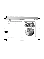
1.5.
Identification data
1) vehicle identification number
2) engine serial number
Motorcycle identification
The motorcycle is identified by the vehicle identification number. When placing orders for spare
parts, in addition to this number, you may be
required to provide the engine serial number, the
color code and the key identification number.
We recommend writing down the main numbers
in the spaces provided below.
VIN No.:
ENGINE No.:
- 13 -
OM_F4 FT_USA_Ed.1.qxd
1-09-2010
16:09
Pagina 14
GENERAL INFORMATION
1
1
Here below you can find a description of a vehicle identification number:
ZCG G C F T W X Y V 000000
Manufacturer’s Letter Code
Motorcycle Type
Progressive vehicle number
The vehicle identification number must be provided each time you need to contact the MV Agusta
Technical Assistance Service, in order to guarantee the traceability of your motorcycle.
- 14 -
OM_F4 FT_USA_Ed.1.qxd
1-09-2010
16:09
Pagina 15
GENERAL INFORMATION
Motorcycle key identification
A key is supplied in duplicate for both the ignition and all
the locks. Keep the duplicate in a safe place.
When placing orders for spare keys, you may be required to provide the key identification number. The key
identification number is located on the MV Code Card
equipped with the ignition keys.
“F4 Frecce Tricolori” identification plate
Your F4 motorcycle has been produced in a limited
series. Each vehicle is identified by a silver plate placed
on the steering head, which reports the number and the
code of the Acrobatic Team’s aeroplane corresponding
to your motorcycle.
- 15 -
1
1
OM_F4 FT_USA_Ed.1.qxd
1-09-2010
16:09
Pagina 16
SAFETY INFORMATION
2.1.
2
Safety
2
2.1.2. NOISE EMISSION WARRANTY
2.1.1. HOW TO REPORT A SAFETY-RELATED
DEFECT
If you believe that your vehicle has a defect
which could cause a crash or could cause injury
or death, you should immediately inform the
National Highway Traffic Safety Administration
(NHTSA) in addition to notifying MV Agusta
S.p.A. If NHTSA receives similar complaints, it
may open an investigation, and if it finds that a
safety defect exists in a group of vehicles, it may
order a recall and remedy campaign. However,
NHTSA cannot become involved in individual
problems between you, your dealer, or MV
Agusta S.p.A. To contact NHTSA, you may either
call the Auto Safety Hotline toll-free at 1-888-3274236 or write to: NHTSA, U.S. Department of
Transportation, 1200 New Jersey Avenue, SE
West Building, Washington, D.C. 20590. You can
also obtain other information about motor vehicle
safety from the Hotline.
MV Agusta S.p.A. warrants that, at the time of
sale, the exhaust system conformed to all applicable U.S. EPA (Environmental Protection Agency)
noise control regulations. The warranty applies to
the first retail purchaser of the exhaust system
and to all subsequent buyers. Any warranty
claims must be addressed to:
MV Agusta U.S.A. LLC, 2300 Maryland Road,
Willow Grove, PA 19090-4193.
2.1.3. NOTE ON TAMPERING
Tampering with the noise control system is prohibited. In particular, federal law prohibits the following acts:
1. The removal or rendering inoperative, other
than for purposes of maintenance, repair, or
replacement, of any device or element of
design incorporated into any new vehicle for the
purpose of noise control prior to its sale or delivery to the ultimate purchaser or while it is in use.
- 16 -
OM_F4 FT_USA_Ed.1.qxd
1-09-2010
16:09
Pagina 17
SAFETY INFORMATION
2. The use of the vehicle after such device or element of design has been removed or rendered
inoperative.
Acts presumed to constitute tampering include:
1. The removal or piercing of the exhaust
silencer, the diaphragm, the manifolds, the catalytic converter or any other components
involved in the transmission of exhaust gases.
2. The removal or piercing of any part of the
intake system.
3. Poor maintenance.
4. The replacement of any movable parts of the
vehicle or of any intake or exhaust components with parts or components other than
those prescribed by the manufacturer.
2
NOTE
Never ride your motorcycle with a defective muffler. This will effect not only the motorcycle’s
sound level, but its performance as well. Riding
with a defective muffler can also subject you to
arrest and imposition of fines.
The rules of the road vary from country to country.
Be sure that you understand local regulations
before riding your motorcycle.
- 17 -
2
OM_F4 FT_USA_Ed.1.qxd
1-09-2010
16:09
Pagina 18
SAFETY INFORMATION
2
2.1.4. INFORMATION ON THE EMISSION CONTROL SYSTEM
The combustion process produces carbon
monoxide and hydrocarbons. Hydrocarbon control is particularly important in that, under certain
conditions and when exposed to direct sunlight,
hydrocarbons undergo reactions which lead to the
formation of photochemical smog. Carbon
monoxide does not react in the same way, but it is
highly toxic. MV Agusta uses a sequential multipoint electronic injection system and other methods designed to cut carbon monoxide and hydrocarbon emissions.
Exhaust emission control system
The exhaust emission control system is made up
of the sequential multipoint injection (SMPI) system, which requires no adjustment. The exhaust
emission control system is distinct from the
crankcase emission control system.
Crankcase emission control system
The engine is equipped with a closed-crankcase
2
system designed to prevent the release of
crankcase emissions into the atmosphere. Blowby gases return to the combustion chamber via
the air filter and the injection system.
Evaporative emission control system
California motorcycles are equipped with an
evaporative emission control system, which consists of a charcoal canister and associated plumbing. This system prevents the escape of fuel
vapors from the fuel tank.
Problems relating to the vehicle’s emissions
Should the vehicle show any of the following
symptoms, contact your MV Agusta dealer to
have it checked and if necessary repaired:
1) Engine is difficult to start or stalls after starting.
2) Idle speed is erratic.
3) Misfiring or backfiring during acceleration.
4) Afterburning.
5) Poor performance (driveability) and excessive
consumption.
- 18 -
OM_F4 FT_USA_Ed.1.qxd
1-09-2010
16:09
Pagina 19
SAFETY INFORMATION
2.1.5. SAFE RIDING
a. The rider’s judgment, training, and experience
form the basis of safe riding. You should practice
riding in areas without traffic, such as an open
parking lot, until you have become familiar with
the motorcycle, its controls and its braking/handling characteristics. In addition to obtaining the
necessary driver’s license, MV Agusta strongly
recommends that you take a certified course
approved by the Motorcycle Safety Foundation
(MSF), which can provide useful information both
to new and experienced riders. For information
about MSF training courses, call the toll-free number: (800) 446-9227. Relying on the advice of
people other than a qualified riding instructor,
even if they are excellent motorcyclists, can be
misleading and dangerous.
b. There are certain risks inherent in riding a
motorcycle because it affords less personal safety
protection than an automobile in the event of an
accident. Unlike automobiles, motorcycles are not
2
equipped with airbags or other protective devices.
Always wear a DOT approved helmet with
eye/face protection and protective clothing, including a motorcycle riding jacket, pants, gloves and
boots, even on short rides. Also, you should wear
clothing that contains bright colors and reflecting
materials to maximize your visibility and presence
to others. Avoid wearing dark colored clothing
because that makes it more difficult for others to
see you on the roadway, even in the daytime.
c. While you are wearing a helmet, you will experience reduced peripheral vision, hearing and
head movement. Please ride accordingly.
d. No helmet or other protective clothing can provide complete protection against the risk of
serious personal injury or even death in the event
of an accident. Do not be deceived by the false
sense of security that you might perceive by wearing even the highest quality protective clothing.
Always use protective equipment as directed in
their owner’s manuals, and ride safely.
- 19 -
2
OM_F4 FT_USA_Ed.1.qxd
1-09-2010
16:09
Pagina 20
SAFETY INFORMATION
2
e. This motorcycle is for riding only on the street
and other paved surfaces. Never ride this
motorcycle off road, on any trails or any unpaved
surfaces.
f. Never attach any key ring or other object to
your ignition key, as they could interfere with your
ability to steer your motorcycle.
g. Never attach a sidecar, trailer or any other
accessory to your motorcycle, as it could make
the motorcycle unstable, resulting in an accident.
h. Never modify any component part of the
motorcycle unless these modifications were
approved in writing by MV Agusta. Non-approved
modifications may jeopardize the structural integrity, functionality and effectiveness of the
motorcycle. Any modifications must be performed
by an authorized MV Agusta dealer with only MV
Agusta approved accessories.
2
i. If your motorcycle is ever involved in an accident, even if it only falls over, check all levers
(hand and foot), wires, hoses, brake calipers, rims
and all other components for any damage. If you
are unsure about the extent of the damage, take
your motorcycle to a MV Agusta dealer. Do not
ride until any damage is repaired by an authorized
MV Agusta dealer.
l. Avoid Carbon Monoxide Poisoning - Never
let the engine run in closed places where the
exhaust fumes may accumulate. Exhaust fumes
contain carbon monoxide that is an odorless and
colorless gas that may cause death or serious
injuries at certain concentration levels. Avoid running the engine indoors. Run engine in open spaces with plenty of ventilation, preferably outdoors,
to eliminate exhaust fumes.
- 20 -
OM_F4 FT_USA_Ed.1.qxd
1-09-2010
16:09
Pagina 21
SAFETY INFORMATION
2
2.1.6. MAINTAINING YOUR MOTORCYCLE
a. Proper maintenance is crucial to safe riding.
Follow all maintenance instructions in this manual
as set forth in Section 6.
b. Maintenance, repair and service of your
motorcycle require specialized knowledge, tools
and experience. General mechanical aptitude
may not be sufficient to properly maintain, repair
or service your motorcycle. These tasks should
be performed by an authorized MV Agusta dealer.
If you have any doubt whatsoever regarding your
motorcycle, please contact an authorized MV
Agusta dealer.
c. If the performance of your motorcycle changes
in any way, if you see any oil, or if it begins to
make any noise, immediately stop riding your
motorcycle. Have your motorcycle professionally
inspected and repaired by an MV Agusta dealer,
as necessary.
- 21 -
2
OM_F4 FT_USA_Ed.1.qxd
1-09-2010
16:09
Pagina 22
SAFETY INFORMATION
2
2.1.7. BEFORE YOU RIDE
2
a. Your motorcycle, like all products, may wear
over time. Before each ride, make sure you
perform all pre-ride checks as stated in Section
4.8 and that all components are properly adjusted
as set forth in Chapter 5.
WARNING
Do not ride your motorcycle if it does
not pass this pre-ride test. Correct any
condition before you ride.
d. Be sure that your tires are inflated to the correct pressure and that there is no damage whatsoever in the tread or sidewall of the tire.
e. Motorcycle riding demands your complete
attention. Do not ride if you are ill, in poor physical condition, under the influence of alcohol or
drugs (prescription or recreational drugs) or are
experiencing emotional issues that could affect
your concentration level.
b. Check your motorcycle for any leaks of oil or
other fluids, which is indicative of a problem with
your motorcycle.
c. Test your brakes at the beginning of the ride to
make sure they are operating properly.
- 22 -
OM_F4 FT_USA_Ed.1.qxd
1-09-2010
16:09
Pagina 23
SAFETY INFORMATION
2
2.1.8. WHILE YOU RIDE
a. Your motorcycle is a very high performance
vehicle. Do not confuse the enhanced capabilities of your motorcycle with your own capabilities. Increasing your skill will take time and practice. Proceed carefully until you are sure you are
competent to handle the capabilities of your
motorcycle.
b. Always ride with care. Adopt a defensive driving attitude to avoid possible accidents.
c. Change gears as necessary to ensure that the
proper gear ratio is chosen in all riding conditions,
allowing the engine to run at optimum speed at all
times. Avoid high gear ratios when traveling at
reduced speed (excessively low rpm) as well as
low gear ratios when traveling at high speed
(excessively high rpm). Improper gear selection
will affect your ability to control your motorcycle.
d. When the motorcycle is being ridden at high
speed, gearing down several times in rapid succession can cause the engine to overspeed. As a
result, the rear wheel may lock, leading to loss of
control of the motorcycle and an accident. In addition, you could damage the engine and transmission. Never gear downmore than one gear at a
time without allowing the engine RPM to stabilize.
e. When riding downhill, reduce the speed of
your motorcycle by closing the throttle and using
a low gear ratio to take advantage of engine
braking. Use the front and rear brakes as little as
possible to maintain your speed, in order to prevent brake overheating and diminished braking
performance.
f. Braking in a turn could result in loss of
motorcycle control. Always operate the brakes
before starting a turn.
- 23 -
2
OM_F4 FT_USA_Ed.1.qxd
1-09-2010
16:09
Pagina 24
SAFETY INFORMATION
2
g. Sudden gusts of wind can cause you to lose
control of your motorcycle. Reduce your speed
and exercise extreme caution when you are overtaken by a vehicle of large dimensions, when you
come out of a tunnel or when you are driving in a
hilly area.
h. Remember that, as your motorcycle picks up
speed, stopping distances increase and the
motorcycle becomes more difficult to control.
2
you do ride in these conditions, travel at low
speed and avoid abrupt maneuvers.
l. Pay attention to roadway conditions. Certain
roadways contain debris, potholes and crevices
that may cause you to lose your balance or control over the motorcycle. Familiarize yourself with
roadway conditions and remain alert so that you
can act to avoid any hazard.
j. Always keep your feet on the foot pegs and
your hands on the handlebars while riding.
m. Never attempt any acrobatic stunts or
maneuvers with your motorcycle! You can lose
control and have an accident. You will also cause
your motorcycle to prematurely wear or fail, resulting in an accident. You will also void your warranty.
k. Avoid riding during slippery road conditions,
such as caused by rain, snow, sleet, ice, loose
gravel, etc. Also, avoid riding on slippery surfaces,
such as metal plates, manholes or grates. You
could experience reduced tire traction, making it
more difficult to control or stop your motorcycle. If
n. Only for the F4 1000 model, you may carry
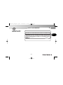
one passenger on the motorcycle. Never carry
more than one passenger. When riding with a
passenger, keep in mind that the passenger’s
weight and movements may affect your balance
and control over the motorcycle.
i. When riding during the day, always ride with
your low beam headlight illuminated.
- 24 -
OM_F4 FT_USA_Ed.1.qxd
1-09-2010
16:09
Pagina 25
SAFETY INFORMATION
o. When transporting items on the motorcycle,
ensure that their weight is distributed evenly and
that they are properly secured. Never attach
anything to your handlebars, front forks or the
frame of your motorcycle, as your steering could
be impared. Loose and improperly positioned
items may interfere with certain motorcycle components and your driving ability, resulting in an
accident.
p. Never exceed the stated speed limit. By avoiding speeding, you reduce the risk of accidents.
Use speed appropriate to the traffic pattern.
Riding at high speed or in competition is to voluntary assume a very high risk of an accident.
2
q. The user of this motorcycle expressly recognizes and agrees that there are risks inherent in
motorcycle riding, including but not limited to the
risk that a component of your motorcycle system
can fail, resulting in an accident, personal injury or
death. By his/her purchase and use of this
motorcycle, the user expressly, voluntarily and
knowingly accepts and assumes these risks,
including but not limited to the risk of passive or
active negligence of MV Agusta or hidden, latent
or obvious defects in the product, and agrees to
hold MV Agusta, its distributors and retailers
harmless to the fullest extent permitted by law
against any resulting damages.
- 25 -
2
OM_F4 FT_USA_Ed.1.qxd
1-09-2010
16:09
Pagina 26
SAFETY INFORMATION
2
2.1.9. AFTER YOU RIDE
2
a. The engine, exhaust pipes and other components will be hot after riding and present a risk of
burn injury to adults or children. Store the
motorcycle in a place that prevents others from
coming in contact with these hot component
parts.
b. Never cover the motorcycle with anything
immediately after riding. Wait until the motorcycle
has thoroughly cooled down. Covering the
motorcycle before the engine and its component
parts thoroughly cooled down presents a risk of
fire and property damage.
c. Park your motorcycle in a location where it is
unlikely to be bumped into by bystanders. Even
slight bumps can cause the motorcycle to fall
over, resulting in property damage, personal
injury, or death, especially to children.
d. Never park your motorcycle on soft or uneven
surfaces because that could cause the motorcycle to topple over, resulting in injury or death to a
bystander. Park your motorcycle on hard, flat and
level surfaces and ensure that the kickstand is
fully engaged and the motorcycle is stable. Avoid
parking on hills or upward sloping terrain, but, if
necessary, park the motorcycle facing uphill.
e. Never wash or clean the motorcycle immediately after riding because hot component parts present a risk of fire when they come in contact with
flammable substances. Wait until the motorcycle
has thoroughly cooled down. Never use washing
or cleaning systems involving steam or high pressure because that could cause damage to the
motorcycle, including the radiator fins.
- 26 -
OM_F4 FT_USA_Ed.1.qxd
1-09-2010
16:09
Pagina 27
SAFETY INFORMATION
2.1.10. INSTALLING ACCESSORIES
MV Agusta provides a range of accessories specially designed for your vehicle. Always select
your accessories with careful consultation with
your MV Agusta dealer to insure that the most
appropriate accessories are selected. It is essential that these accessories are installed only by an
MV Agusta dealer.
WARNING: Use only MV Agusta original
accessories. The use of non-genuine
accessories can make the vehicle
unsafe by reducing its handling, stability
or the effectiveness of the braking system. For this reason, the installation of
any non-genuine accessory makes the
warranty null and void and relieves MV
Agusta of all its warranty obligations.
Every time you install accessories that affect
the weight and/or the aerodynamic characteristics
of your motorcycle, they must be assembled on its
2
lower side and near to its center, as much as it is
possible. Any connecting brackets and anchor
bolts must be carefully checked after the assembly, to ensure a stable framework and an unmovable support for the accessory.
WARNING
Improperly installed accessories can
result in an accident that could lead to
serious personal injury or even death.
Verify that the installed accessories do not
cause a reduction of the minimum ground clearance and of the inclination of your motorcycle.
Moreover, verify that the installed accessories do
not cause any interference with the handling of
the steering system, with the travel of the suspensions and/or with the movement of any other component involved in driving.
Any accessory positioned on the handlebar or
on the front fork can reduce the handling and
adversely affect the stability of the vehicle.
Therefore, the choice of the accessories should
- 27 -
2
OM_F4 FT_USA_Ed.1.qxd
1-09-2010
16:09
Pagina 28
2
SAFETY INFORMATION
2
be accurate and restricted to components of light
weight and small dimensions only.
Blowing winds, including that cause by passing large vehicles, can affect the stability of your
motorcycle whether or not it is equipped with
accessories. Improperly selected or installed
accessories increase the risk of instability. It is
therefore necessary to pay great attention in
choosing and installing any accessories.
Some accessories may force the rider to drive
in an unnatural position. This may obviously
restrict your freedom of movement and cause loss
of control of the motorcycle that could result in an
accident with subsequent serious injury or even
death. If any accessory results in an unnatural
riding position, immediately see your MV Agusta
dealer before riding your motorcycle.
Adding electric accessories can cause an
overload of the electrical system of your motorcycle, resulting in damage to the wires and electrical
system, short circuit, electric shock, a fire, serious
injury or even death.
2.1.11. VEHICLE LOAD
Your motorcycle is designed for use by the rider
and only one passenger. To use the vehicle in
complete safety, it is essential that the following
maximum weight conditions are never exceeded:
F4 1000 “Frecce Tricolori”
378 kg (833 lbs)
These values are also shown on the plate fixed to
the left side of the steering head tube. They come
out from the sum of the following weights:
•
•
•
•
- 28 -
weight of the motorcycle;
weight of the driver;
weight of the passenger;
weight of the load and all the accessories.
OM_F4 FT_USA_Ed.1.qxd
1-09-2010
16:09
Pagina 29
SAFETY INFORMATION
WARNING
NEVER OVERLOAD YOUR MOTORCYCLE! Driving an overloaded motorcycle
can cause damage to the tires, brakes or
other structural components of your
motorcycle and result in serious injury
or even death. Verify that the total weight (including the weight of the
motorcycle, the driver, the passenger,
the load and all the accessories) does
not exceed the maximum weight value
specified for your vehicle.
WARNING
The load on your motorcycle can strongly affect handling, braking, performance and safety characteristics of your
motorcycle. You will need additional
time to brake, turn, and will need to ride
at a slower rate of speed. Please ride
accordingly.
- 29 -
2
WARNING
Never carry any incorrectly secured
object on your motorcycle, which might
shift or fall away during riding that could
affect the motorcycle stability. Steadily
fasten the heaviest objects near the center of the motorcycle, and equally divide
the load on both sides of the motorcycle.
WARNING
• Never insert any object or accessory
in the open spaces on the frame, in
order to avoid interferring with the
movable parts of the motorcycle.
• Before riding with a load, always check
the wear and the pressure of the tires.
• Adjust the suspensions according to
the load.
• Even if the motorcycle is correctly
loaded, drive with caution and never
exceed 130 km/h (80 mph) when you
carry a load.
2
OM_F4 FT_USA_Ed.1.qxd
1-09-2010
16:09
Pagina 30
SAFETY INFORMATION
2.1.13. COMPETITIONS
2.1.12. MODIFICATIONS
2
2
Never remove any original device, or modify the
motorcycle in any way that could change its
shape or operation.
WARNING
Any modifications made to the motorcycle (e.g. alteration and/or removal of
components) as these modifications
can make the vehicle unsafe and/or illegal. MV Agusta is not responsible for
any damage to people and objects as a
result of modifications made to the original condition of your motorcycle.
Modifying the motorcycle immediately
voids the warranty and relieves MV
Agusta of all its warranty obligations.
WARNING
Riding the motorcycle in competitions
requires considerable skill and experience as well as an appropriate setup of
the motorcycle.
CAUTION
The high temperatures caused by the
use of the motorcycle on race circuits
could compromise the efficiency of the
catalytic converter and of the exhaust
system; therefore, we suggest assembling a special exhaust system when
using the vehicle on race circuits.
MV Agusta has designed a number of special
components for use in competitions and/or sporting events. The use of such components is strictly limited to areas closed to traffic. Failure to
observe this warning violates the law.
- 30 -
OM_F4 FT_USA_Ed.1.qxd
1-09-2010
16:09
Pagina 31
SAFETY INFORMATION
2
2.1.14. SUGGESTIONS AGAINST THEFT
1. Every time you park your motorcycle, operate
the steering lock and remove the ignition key
(see § 3.5.).
2. Park your motorcycle in a closed garage every
time it is possible.
3. Install a good quality anti-theft device on your
vehicle.
4. Always keep up to date the registration data of
your motorcycle.
5. Write down your name, address and phone
number in the spaces provided, and always
keep this owner’s manual inside the glove
compartment of your motorcycle (see § 4.6.).
This is very important, because a stolen
motorcycle can be subsequently identified by
reading the informations written in the manual
found inside it.
NAME:
ADDRESS:
PHONE NUMBER:
- 31 -
2
OM_F4 FT_USA_Ed.1.qxd
1-09-2010
16:09
Pagina 32
2
SAFETY INFORMATION
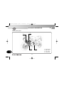
2.2.
2
1
2
3
4
5
6
7
-
8910 11 12 13 -
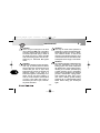
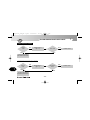
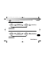
Safety Labels - Location
Front fairing function
Documentation warning
Battery warning
Unleaded gasoline
Emission control
Information on emission control
Information on gas emissions,
exhaust silencers
Certification-Tire Information
Front fork foot warning
Rearview mirrors
Rear shock absorber
Chain adjustment
Rear wheel hub warning
10
10
1
5
3
4
6
2
7
8
11
NOTE: The labels in the following
pages do not appear in their real size.
If you experience difficulties in understanding any of these labels, contact
an authorized MV Agusta dealer.
9
- 32 -
12
13
OM_F4 FT_USA_Ed.1.qxd
1-09-2010
16:09
Pagina 33
SAFETY INFORMATION
2
1. ADHESIVE LABEL –
FRONT FAIRING
FUNCTION
2
2. ADHESIVE LABEL –
DOCUMENTATION
WARNING
- 33 -
OM_F4 FT_USA_Ed.1.qxd
1-09-2010
16:09
Pagina 34
SAFETY INFORMATION
3. ADHESIVE LABEL –
BATTERY WARNING
2
4. ADHESIVE LABEL –
UNLEADED GASOLINE
- 34 -
2
OM_F4 FT_USA_Ed.1.qxd
1-09-2010
16:09
Pagina 35
2
SAFETY INFORMATION
5. ADHESIVE LABEL –
EMISSION CONTROL
M O TO R C Y C L E N O I S E E M I S S I O N C O N T R O L I N F O R M AT I O N
THIS 2010 MVA44F1000 MOTORCYCLE, MEETS US EPA NOISE EMISSION
REQUIREMENT OF 80 dBA AT 7095 RPM BY THE FEDERAL TEST PROCEDURE.
MODIFICATIONS WHICH CAUSE THIS MOTORCYCLE TO EXCEED FEDERAL NOISE
STANDARDS ARE PROHIBITED BY FEDERAL LAW. SEE OWNER'S MANUAL.
Motor S.p.A. VARESE - ITALY
8000B3697
- 35 -
2
OM_F4 FT_USA_Ed.1.qxd
1-09-2010
16:09
Pagina 36
2
SAFETY INFORMATION
2
VEHICLE EMISSION CONTROL INFORMATION
THIS VEHICLE CONFORMS TO US EPA AND CALIFORNIA
ENGINE DISPLACEMENT : 998 cc
REGULATIONS APPLICABLE TO 2010 MODEL YEAR
ENGINE FAMILY : AMVAC.998 MHC
ENGINE EXHAUST CONTROL SYSTEM: NEW MOTORCYCLES AND IS CERTIFIED TO 0.8 g/km HC + NOx,
12.0 g/km CO EXHAUST EMISSION STANDARD IN CALIFORNIA
TWC + SFI + PAIR + H02S
ENGINE TUNE-UP SPECIFICATIONS AND ADJUSTMENT
ITEM
SPECIFICATIONS
INSTRUCTIONS
No Adjustment
IGNITION TIMING :
IDLE SPEED RPM (NEUTRAL) :
1150 +- 100
No Adjustment
IDLE MIXTURE :
.
.
VALVE CLEARANCE (mm) : IN 0.15 . 0.24 / EX 0.20 . 0.29
See Service Manual
SPARK PLUG : NGK CR9 EB GAP (mm): 0.7 .. 0.8
FUEL SPECIFICATIONS
UNLEADED OCTANE
OIL : SAE 10 W 60
90 R + M/2
TYPE : SYNTHETIC A.P.I. SJ
EVAPORATIVE FAMILY: AMVAU0018MHC
PERMEATION FAMILY: AMVAPP105R01
CANISTER
HOT AIR INLET
MANIFOLD 4
MANIFOLD 3
JET
MANIFOLD 2
MANIFOLD 1
Motor s.p.a. VARESE - ITALY
MV AGUSTA USA LLC - WILLOW GROVE, PA
- 36 -
8000B3698
6. ADHESIVE LABEL –
INFORMATION ON
EMISSION CONTROL
OM_F4 FT_USA_Ed.1.qxd
1-09-2010
16:09
Pagina 37
SAFETY INFORMATION
2
7. STAMPING ON EXHAUST
SILENCERS –
EMISSION INFORMATION
2
- 37 -
OM_F4 FT_USA_Ed.1.qxd
1-09-2010
16:09
Pagina 38
2
SAFETY INFORMATION
8. ADHESIVE LABEL –
CERTIFICATION – TIRE
INFORMATION
2
MANUFACTURED BY :
Motor S.p.A.
DATE :
VARESE - ITALY
TYPE OF VEHICLE: MOTORCYCLE
GVWR 833 lbs 378 kg
VIN:
TIRE - DIMENSION - RIM
COLD INFL. PRESS.
GAW R
kPa
psi
lbs kg
33.0
227
F 337 153 120 /70 ZR 17 M/C ( 58W ) 3.50 x 17
R 556 252 190/55 ZR 17 M/C ( 75W )
6.00 x 17
33.0
227
THIS VEHICLE CONFORMS TO ALL APPLICABLE FEDERAL MOTOR VEHICLE
SAFETY STANDARDS IN EFFECT ON THE DATE OF MANUFACTURE SHOWN ABOVE.
8000B3696
9. ADHESIVE LABEL –
FRONT FORK FOOT
WARNING
- 38 -
OM_F4 FT_USA_Ed.1.qxd
1-09-2010
16:09
Pagina 39
2
SAFETY INFORMATION
10. ADHESIVE LABEL –
REARVIEW MIRRORS
OBJECTS IN MIRROR ARE CLOSER
THAN THEY APPEAR
11. ADHESIVE LABEL –
REAR SHOCK ABSORBER
WARNING
CONTAINS HIGHLY COMPRESSED GAS
USE ONLY PERFECTLY DRY NITROGEN GAS
OTHER GASES MAY CAUSE EXPLOSION
DO NOT INCINERATE REFER TO OWNER’S
MANUAL FOR REGULATING GAS
SACHS
- 39 -
2
OM_F4 FT_USA_Ed.1.qxd
1-09-2010
16:09
Pagina 40
SAFETY INFORMATION
12. ADHESIVE LABEL –
CHAIN ADJUSTMENT
2
13. ADHESIVE LABEL –
REAR WHEEL HUB
WARNING
- 40 -
2
OM_F4 FT_USA_Ed.1.qxd
1-09-2010
16:09
Pagina 41
2
SAFETY INFORMATION
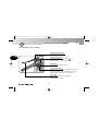
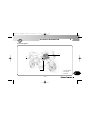
2.3. Safety - Visual and acoustic signals
Before each ride, it is essential to verify the operation of the visual and acoustic signals.
2
Turn indicators (§3.3.)
Rear side reflector
Rear side reflector
Horn (§3.3.)
Parking lights, low
and high beams (§3.3.)
Parking light (§3.3.) and brake light
(lights up operating the brakes)
Turn indicators (§3.3.)
Rear reflector
Plate light (lights up when
Front side reflector
parking lights are turned on)
- 41 -
OM_F4 FT_USA_Ed.1.qxd
1-09-2010
16:09
Pagina 42
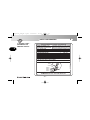
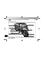
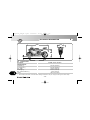
CONTROLS AND INSTRUMENTS
3
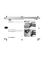
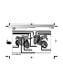
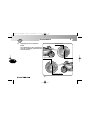
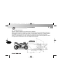
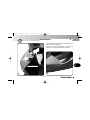
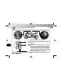
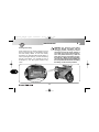
3.1. Location of controls and instruments
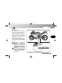
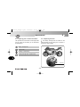
Instruments and warning lights (§3.7.)
Rearview mirror (§5.1.)
Rearview mirror (§5.1.)
Front brake lever (§5.1.)
Clutch lever (§5.1.)
3
Left handlebar electrical controls (§3.3.)
Throttle twist grip (§3.4.)
Ignition switch and steering lock (§3.5.)
Right handlebar electrical controls (§3.4.)
Fuel tank cap (§4.5.)
Gear lever (§3.6. and §5.1.)
Rear brake lever (§5.1.)
Sidestand (§3.2.)
Right side
Left side
- 42 -
OM_F4 FT_USA_Ed.1.qxd
1-09-2010
16:09
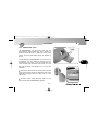
Pagina 43
3
CONTROLS AND INSTRUMENTS
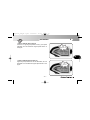
3.2. Kickstand
The kickstand is equipped with a safety switch that prevents motorcycle
operation while the stand is down.
If the rider attempts to engage the
gears while the engine is running and
the stand is down, the safety switch
automatically turns off the engine by
cutting the current supply.
If the motorcycle is parked (kickstand
down) and the gears are engaged, the
switch prevents the engine from being
started.
3
Safety switch
WARNING: Riding with the
kickstand
incompletely
retracted can result in an
accident when you turn left.
Always retract the kickstand
completely before starting off.
WARNING: At least once
each month, check that the
safety switch is properly activated by the kickstand and is
operational.
Kickstand
Dual return
spring
- 43 -
OM_F4 FT_USA_Ed.1.qxd
1-09-2010
16:09
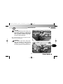
Pagina 44
CONTROLS AND INSTRUMENTS
3
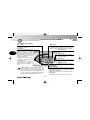
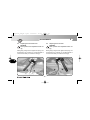
3.3. Handlebar controls, left side
High beam flasher button
Press the button repeatedly.
3
Low/high beam button
Button not pressed in
: low beam
Button pressed in
: high beam
Horn button
Press to operate the warning horn.
Turn indicator switch
Shifting the lever to the left or right switches on the left
or right turn indicators. The switch then returns to the
central position. Press to turn off the indicators.
Clutch lever
Move towards/away from the handgrip to
release/engage the clutch.
- 44 -
OM_F4 FT_USA_Ed.1.qxd
1-09-2010
16:09
Pagina 45
CONTROLS AND INSTRUMENTS
3
High beam flasher button
It is used to attract the attention of other road users in case of danger or emergency. When the high
beam is on, the button is inactive.
Low/high beam button
Under normal conditions, the low beam is on. The high beam can be switched on by pressing the button when allowed by the traffic and road conditions.
Horn button
It is used to attract the attention of other road users in case of danger or emergency.
Turn indicator switch
It is used to show the rider’s intention to change direction or lane.
WARNING
Always use your turn indicators correctly. Use them to signal your intention before you
start a turn, and turn them off when you have completed the turn. Failure to observe this
warning could lead other users of the road to draw incorrect conclusions about your intentions and the motion of your motorcycle, resulting in a collision, with subsequent serious
personal injury or even death.
Clutch lever
It engages/disengages the clutch through a hydraulically controlled device.
- 45 -
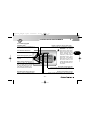
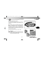
3
OM_F4 FT_USA_Ed.1.qxd
1-09-2010
16:09
Pagina 46
CONTROLS AND INSTRUMENTS
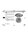
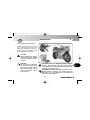
3.4. Handlebar controls, right side
Engine stop switch
Stops the engine and prevents it from being restarted.
3
Engine start button
Starts the engine. To be released as soon as the engine starts.
When the engine is running, pressing the button selects the
display functions.
Cold start (choke) lever
Rotate clockwise when cold starting. After the engine has run for
a few seconds, return the lever to its original position.
Throttle twist grip
Rotate counterclockwise to increase engine speed.
Front brake lever
Pull to the lever to apply the front brake.
- 46 -
3
OM_F4 FT_USA_Ed.1.qxd
1-09-2010
16:09
Pagina 47
CONTROLS AND INSTRUMENTS
3
Engine stop switch
It is used to switch off the engine in an emergency. The ignition circuit is disabled, preventing the engine
from being restarted. To be able to restart the engine, return the switch to its original position.
DANGER! If the throttle of your motorcycle sticks, you must use the engine stop switch to
stop the delivery of power from the engine. Failure to use the stop switch in such a situation can result in loss of control of your motorcycle, serious injury or even death.
DANGER! Before restarting the engine, you must determine the cause of the stuck throttle
and effect the necessary repair. If necessary, take your motorcycle to a qualified mechanic. Failure to do so could result in an accident, personal injury or death.
NOTE
Under normal conditions, do not use this switch to shut off the engine.
Engine start button
It is used to start the engine and, when the engine is running, to select the different functions of the display installed on the instrument panel.
CAUTION: To avoid damaging the electrical equipment, be sure not to hold down the button for longer than 5 consecutive seconds.
If, after some attempts, the engine does not start, refer to the chapter “TROUBLESHOOTING” later in this manual.
- 47 -
3
OM_F4 FT_USA_Ed.1.qxd
1-09-2010
16:09
Pagina 48
CONTROLS AND INSTRUMENTS
3
Cold start (choke) lever
It facilitates cold starting by slightly enrichening the fuel-air mixture during start-up.
NOTE: Apply the choke lever for as short a period as possible. Once the engine idles normally,
return the lever to its original position.
3
Throttle twist grip
It controls the fuel-air mixture supplied to the engine, which regulates engine speed. To increase engine
speed, rotate the hand grip from its idle position counterclockwise.
When cold starting (choke on), rotating the throttle twist grip clockwise fully and repeatedly causes the
choke lever to return to its original position.
Front brake lever
It controls a hydraulic circuit that operates the front wheel braking system.
Proper use of the front brake is critical to achieve maximum braking performance of your motorcycle. MV
Agusta strongly recommends that you take a motorcycle riders training course to learn how to properly
use the front brake.
WARNING: Improper use of the front brake can result in loss of control of the motorcycle,
an accident, personal injury or death.
WARNING: Exercise extreme caution when using the front brake on wet or slippery surfaces, or on surfaces covered with sand, loose gravel, etc.
- 48 -
OM_F4 FT_USA_Ed.1.qxd
1-09-2010
16:09
Pagina 49
3
CONTROLS AND INSTRUMENTS
3.5. Ignition switch and steering lock
WARNING: Never attach a ring or any other
object to the ignition key as they may hinder the
steering action. Failure to observe this warning
can lead to loss of control of the motorcycle,
resulting in an accident, personal injury or death.
WARNING
Never attempt to change the switch functions
while you are riding. This could cause loss of
control of the motorcycle, resulting in an accident, personal injury or death.
The ignition switch enables and disables the electrical
circuit and the steering lock. The four positions of the
switch are described below.
OFF position
All electrical circuits are deactivated. The key can be
removed.
ON position
All electrical circuits are activated. The instruments and
warning lights perform the self-diagnostic cycle. The
engine can be started. The key cannot be removed.
- 49 -
3
“OFF”
“ON”
CAUTION
Do not leave the key on the ON
position for a long time when the
engine is not running, in order to
avoid damage to the electrical
parts of the motorcycle.
OM_F4 FT_USA_Ed.1.qxd
1-09-2010
16:09
Pagina 50
CONTROLS AND INSTRUMENTS
3
LOCK position
Turn the handlebar to the left or right. Press the key in
gently while rotating it to the LOCK position.
All electrical circuits are deactivated and the steering is
locked. The key can be removed.
3
Left side
- 50 -
Right side
OM_F4 FT_USA_Ed.1.qxd
1-09-2010
16:09
Pagina 51
3
CONTROLS AND INSTRUMENTS
P (PARKING) position
Turn the key from the LOCK position to the P position.
All electrical circuits are deactivated except the parking
lights. The steering is locked. The key can be removed.
CAUTION
Do not leave the key on the P position for a
long time, in order to avoid discharging the
battery of your motorcycle.
3.6. Gear lever
The N (neutral) position is indicated by the indicator light
on the instrument panel.
To change into first gear, push the lever down.
To change into second gear, lift the lever up. Lifting the
lever up repeatedly engages all the other gears in succession up to the sixth speed.
3
6°
5°
4°
3°
2°
N
1°
- 51 -
OM_F4 FT_USA_Ed.1.qxd
1-09-2010
16:09
Pagina 52
CONTROLS AND INSTRUMENTS
3
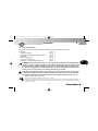
3.7. Instruments and warning lights
The instruments and warning lights are activated by turning the ignition switch
to the ON position. After a preliminary check (approx. 7 seconds) the displayed
information reflects the current general condition of the motorcycle.
3
Warning lights
(§3.7.1.)
SET button
(§3.7.2.)
Tachometer display
OK button
(§3.7.2.)
Multifunction display (§3.7.2.)
HAZARD button (§3.7.2.)
- 52 -
OM_F4 FT_USA_Ed.1.qxd
1-09-2010
16:09
Pagina 53
CONTROLS AND INSTRUMENTS
3
3.7.1. Warning lights
Headlights (blue)
It turns on when the headlights are on.
Engine oil pressure warning lights (red)
Lights up when the oil pressure is insufficient.
WARNING: If the warning
light comes on while riding,
stop the motorcycle immediately. Check the oil level
and if necessary have it
restored by a MV Agusta
authorized service center
(see §3.8.). If the warning
light comes on even if the
oil level is correct, do not
resume riding and contact a
MV Agusta authorized service center.
Turn indicator light (green)
Lights up when the turn indicators are activated.
Neutral warning lights (green)
It turns on when the gear is in
“Neutral”.
Battery charge indicator (red)
Lights up when the alternator
does not supply enough current
to charge the battery. If the indicator comes on while riding, contact an authorized service center.
Rev limiter warning light (red)
It turns on when the engine exceeds 10800 rpm;
the rev limiter limits the rpm to 13500.
Reserve fuel indicator (orange)
Comes on when approximately 4 litres of fuel are left.
Sidestand down warning light (red)
Lights up when the sidestand is down.
- 53 -
3
OM_F4 FT_USA_Ed.1.qxd
1-09-2010
16:09
Pagina 54
CONTROLS AND INSTRUMENTS
3
3.7.2. Multifunction display
Gear display
It displays the currently engaged gear.
“N” stands for “neutral”.
3
Speedometer
It displays the speed of the motorbike. It can be given
in kilometres per hour (Km/h) or in miles per hour
(Mph). The full scale measures 350Km/h (217 Mph).
“SPORT” Mode
It puts the injection unit in Sport
Mode.
“SET” button
Press it to select and set the figures on the display.
Thermometer
It displays the temperature of the
coolant by turning on a variable
number of segments on a graduated scale. When the temperature
falls outside the normal operating
range, it may display one of the
following information:
- the display shows just one blinking segment; it means that the
temperature is low;
- all segments are on, while the
upper segment is blinking; it
means that the temperature is
high.
“OK” button
Press it to confirm the new settings.
“HAZARD” button
Press it to turn on the emergency
lights.
“TOTAL” odometer:
Danger - Notice: if the temperature is high, stop
the motorbike and check the coolant level. If it
needs to be filled up, contact a MV Agusta licensed
service center (see § 6.3). If the warning light turns
on even if the level is adequate, stop driving and
contact a MV Agusta licensed service center.
- 54 -
It displays the total distance covered; from 0 to 999999 (Km or miles)
Trip counter 1, “TRIP 1”
It displays the length of a trip; from 0 to 999.9 (Km or miles)
Trip counter 2, “TRIP 2”
It displays the length of a trip; from 0 to 999.9 (Km or miles)
Chronometer
It displays the time measured by the chronometer
OM_F4 FT_USA_Ed.1.qxd
1-09-2010
16:09
Pagina 55
4
OPERATION
4.1. Using the motorcycle
This section provides the basic information needed to correctly operate the motorcycle:
–
–
–
–
–
–
–
Break-in
Starting the engine
Selecting and setting the display functions
Refuelling
Glove compartment
Parking the motorcycle
Checks to be performed before riding
(
(
(
(
(
(
(
§
§
§
§
§
§
§
4.2.
4.3.
4.4.
4.5.
4.6.
4.7.
4.8.
)
)
)
)
)
)
)
WARNING: Your motorcycle possesses very high power and performance characteristics.
Therefore, its use requires a higher level of motorcycle riding skill and knowledge of the
motorcycle. When you begin riding this motorcycle, you must ride especially carefully until
you are thoroughly familiar with the motorcycle’s power and performance characteristics.
Failure to do so could result in an accident, personal injury or death.
CAUTION: The high temperatures caused by the use of the vehicle on race circuits could
compromise the efficiency of the catalytic converter and of the exhaust system; therefore,
we suggest installing a special exhaust system when using the vehicle on race circuits.
Respect and defend natural environment
Everything we do affects the whole planet as well as its resources.
MV Agusta, in order to protect the interests of the community, alerts the Customers and the Technical Assistance operators
to use the vehicle and dispose of its replaced parts respecting the laws in force concerning environmental pollution and waste
disposal and recycling.
- 55 -
4
OM_F4 FT_USA_Ed.1.qxd
1-09-2010
16:09
Pagina 56
4
OPERATION
4.2
Break-in
CAUTION
Failure to observe the indications provided
below can reduce performance and shorten
the life of the motorcycle.
4
Break-in is generally considered to apply only to the
engine. In fact, it should be regarded as an essential
phase for other important parts such as the tires, the
brakes and the drive chain. During the very first miles,
adopt a relaxed riding style.
0 to 500 km (0 to 300 mi) (A)
Frequently change the engine speed. If possible, prefer
hilly routes with gentle slopes and many bends. Avoid
long straight stretches.
- 56 -
MAX
5500-6000 rpm
WARNING: New tires are sometimes coated with a mold release
agent which makes them slippery.
Abrupt acceleration, sharp turning
or hard braking could cause you
to lose control of your motorcycle.
Ride at reduced speeds and exercise extreme caution during the
first 100 km (62 miles) when the
motorcycle is new and after the
replacement of a tire.
OM_F4 FT_USA_Ed.1.qxd
1-09-2010
16:09
Pagina 57
4
OPERATION
500 to 1000 km (300 to 600 mi)
Avoid low or high engine speeds and vary your speed
frequently. Do not exceed the engine speed shown in
the figure.
MAX
8000-9000 rpm
4
1000 to 2500 km (600 to 1600 mi)
Higher engine performance can be demanded, but it is
advisable not to exceed the engine speed shown in the
figure.
- 57 -
MAX
11000 rpm
OM_F4 FT_USA_Ed.1.qxd
1-09-2010
16:09
Pagina 58
OPERATION
4.3.
Starting the engine
WARNING
Starting the engine in a closed place can be
dangerous. Exhaust emissions contain carbon monoxide, a colorless and odorless gas
that can lead to serious harm or even death
when inhaled.
Only start the engine outdoor, in the open air.
4
As you turn the ignition switch to the ON position, the
instruments and the warning lights will go through the
self-diagnostic cycle; during this phase, make sure that
all the warning lights on the dashboard come on. One of
the following conditions must be verified, in order that
the ignition switch system allows engine starting:
– The gears are in neutral.
– The gears are engaged, the clutch lever is pulled
and the kickstand is up.
- 58 -
4
OM_F4 FT_USA_Ed.1.qxd
1-09-2010
16:09
Pagina 59
OPERATION
4
If the self-diagnostic cycle detects a fault in the vehicle, the display shows the warning alert shown in the
picture. In particular, this message highlights the vehicle
part or device on which the fault has been detected.
4
Press “OK” button to access to “RUN” mode.
WARNING
If a fault is detected on the vehicle, do not
start engine and contact an authorized MV
Agusta center.
- 59 -
OM_F4 FT_USA_Ed.1.qxd
1-09-2010
16:09
Pagina 60
4
OPERATION
Cold starting
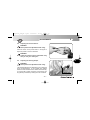
Turn the “CHOKE” lever without turning the accelerator handle.
CHOKE lever
4
Press the starter button.
START button
As soon as the engine starts, release the button and
when just slightly warmed up bring the “CHOKE” lever
back to its starting position.
- 60 -
CHOKE lever
OM_F4 FT_USA_Ed.1.qxd
1-09-2010
16:09
Pagina 61
OPERATION
Hot starting
4
START button
Press the start button without turning the throttle
twist grip.
As soon as the engine starts, release the button.
CAUTION
• Do not press the start button for longer than
5 consecutive seconds, in order to avoid damage to the electrical equipment.
• Avoid warming up the engine while the vehicle is stationary. The subsequent engine overheating can cause damage to the internal
parts of the engine. It is advisable to bring the
engine to the working temperature by riding
at reduced speed.
• To ensure the maximum life of the engine,
never speed up at full throttle when the engine is cold.
- 61 -
4
OM_F4 FT_USA_Ed.1.qxd
1-09-2010
16:09
Pagina 62
OPERATION
4.4.
Selecting and setting the display functions
Some of the main measurements of the instruments
may be changed.
The available options include:
- Select an operating mode:
4
“RUN” (Odometer)
“TC” (Traction control)
“CHRONO” (Chronometer)
“NIGHT/DAY” (Night/Day Mode)
- Reset the trip counter:
Trip counter 1
Trip counter 2
“TRIP 1”
“TRIP 2”
- Turn on the chronometer
- “IMMOBILIZER” mode (Antitheft device)
- Control unit mapping selection
- 62 -
4
OM_F4 FT_USA_Ed.1.qxd
1-09-2010
16:09
Pagina 63
OPERATION
4
4.4.1. Selecting the display functions
The following settings may be changed
on the display:
•
•
•
•
“RUN” (Odometer)
“TC” (Traction control)
“CHRONO” (Chronometer)
“NIGHT/DAY” (Night/Day Mode)
4
To display the operating modes, press
“SET” for less than four seconds. When
pressed, the display shows all modes,
in a sequence. Select the desired
mode.
WARNING
The operation must be performed while the engine is
not running, the gears are in neutral, the motorcycle
is stationary, and with the feet on the ground. Do not
set the display functions while riding.
- 63 -
OM_F4 FT_USA_Ed.1.qxd
1-09-2010
16:09
Pagina 64
OPERATION
“RUN” mode
In addition to the speedometer, the display shows the
following functions (see §4.4.2.):
• Total odometer
• Trip counter 1
“TOTAL”
“TRIP 1”
As an alternative:
4
• Total odometer
• Trip counter 2
“TOTAL”
“TRIP 2”
“TC” Mode
This Mode adjusts the engine traction control level to
your driving requirements (see §4.4.3.).
- 64 -
4
OM_F4 FT_USA_Ed.1.qxd
1-09-2010
16:09
Pagina 65
OPERATION
4
“CHRONO” Mode
This mode turns on the Chronometer and saves the
recorded information (see §4.4.4.).
The following is displayed:
•
•
•
•
Chronometer
Chronometer
Chronometer
Rev counter
Current lap
Fastest lap
Last lap
Total laps covered
“CURRENT LAP”
“BEST LAP”
“LAST LAP”
“N° LAP”
4
“NIGHT/DAY” Mode
This function enables the background colour of the display to be converted in order to adapt its visibility
depending on the time of day or night the vehicle is used
(see §4.4.5.).
- 65 -
OM_F4 FT_USA_Ed.1.qxd
1-09-2010
16:09
Pagina 66
OPERATION
4.4.2. Trip reset
To reset “TRIP 1” and “TRIP 2”, proceed as follows.
4
WARNING
The display modes may be changed or set
when the engine is off, the gear in neutral, the
motorbike stationary with your feet on the
ground. The display may not be changed
while driving.
Access the “RUN” mode; the total speedometer
("TOTAL”) and partial speedometer 1 (“TRIP 1”) will
appear on the display.
By pressing the “OK” key for more than four seconds, the “TRIP 1” value will be reset to zero.
- 66 -
4
OM_F4 FT_USA_Ed.1.qxd
1-09-2010
16:09
Pagina 67
OPERATION
4
Press the “OK” key for less than four seconds until
the partial speedometer 2 function (“TRIP 2”) appears
on the display.
4
By pressing the “OK” key for more than four seconds, the “TRIP 2” value will be reset to zero.
- 67 -
OM_F4 FT_USA_Ed.1.qxd
1-09-2010
16:09
Pagina 68
OPERATION
4.4.3. “TC” Mode
Press “SET” in order to access to “TC” mode, then
press “OK” for less than four seconds until “TC LEVEL”
appears. The current traction control level is the same
as the one shown on the display.
4
WARNING
The display modes may be changed or set
when the engine is off, the gear in neutral, the
motorbike stationary with your feet on the
ground. Do not change the display while driving.
Press “SET” for less than four seconds: the traction
control level rises up to the next value. Such value may
range between 0 and 8.
Press “OK” for over four seconds to confirm the
selected traction control level.
- 68 -
4
OM_F4 FT_USA_Ed.1.qxd
1-09-2010
16:09
Pagina 69
OPERATION
4
4.4.4. Chronometer
Lap time recording
Turn on the chronometer (“CHRONO” mode) to
record the time taken to cover a lap.
4
Press the headlight button to start recording the
time. The colon that separates the minutes from the
seconds and from the tenths of a second will start blinking. Now, the instrument is recording the time.
- 69 -
OM_F4 FT_USA_Ed.1.qxd
1-09-2010
16:09
Pagina 70
OPERATION
Press the headlight button again to record the time
taken to cover the 1st lap. At the same time, the instrument starts recording the time taken to cover the second lap.
The time measurement for the first lap is stored in the
memory and is visualised on the display for ten seconds, after which the time measurement for the following lap appears.
4
If using the chronometer again, every time you press
the headlight button, it records a time. The instrument
can record up to100 consecutive times.
When the time for the lap which has just concluded is displayed, the symbol “+” or “-” appears if the time recorded
is respectively higher or lower than the time measured
during the previous lap.
- 70 -
4
OM_F4 FT_USA_Ed.1.qxd
1-09-2010
16:09
Pagina 71
OPERATION
4
Data display
Once all times have been recorded, they may be
displayed.
Access the “CHRONO” mode; the time of the fastest
lap (“BEST LAP”) and the time of the last lap (“LAST
LAP”) appears on the display.
WARNING
The display modes may be changed or set
when the engine is off, the gear must be in
neutral, the motorbike must be stationary with
your feet on the ground. Do not change the
display while driving.
Press “OK” for less than four seconds until “LAPS
VIEW” appears.
- 71 -
4
OM_F4 FT_USA_Ed.1.qxd
1-09-2010
16:09
Pagina 72
4
OPERATION
By repeatedly pressing the key of the flashing high
beam headlight, all the times previously acquired starting from the last lap memorised can be displayed in
sequence.
4
Once all the data have been displayed, press the
“SET” key to return to the “LAPS VIEW” mode and then
to the following mode.
- 72 -
OM_F4 FT_USA_Ed.1.qxd
1-09-2010
16:09
Pagina 73
OPERATION
4
How to delete data
To delete the saved data, proceed as follows:
WARNING
The display modes may be changed or set
when the engine is off, the gear in neutral, the
motorbike stationary with your feet on the
ground. Do not change the display while driving.
Resetting of individual time recordings: Access the
“CHRONO” mode and press the “SET” key for less than
four seconds until the words “SINGLE LAP RESET”
appear on the display.
Press the “OK” key for less than four seconds; the
value of the last lap time memorised will start flashing.
- 73 -
4
OM_F4 FT_USA_Ed.1.qxd
1-09-2010
16:09
Pagina 74
OPERATION
Now, press “OK” for over four seconds to delete the
value. Otherwise, press “SET” for less than four seconds to stop the deletion procedure.
4
Subsequently, by pressing the flashing high beam
headlight key followed by the “OK” key for more than
four seconds, all the previously acquired times can be
cancelled.
Once all the data have been cancelled, press the
“SET” key to return to the “LAPS VIEW” mode and then
to the following mode.
- 74 -
4
OM_F4 FT_USA_Ed.1.qxd
1-09-2010
16:09
Pagina 75
OPERATION
4
Resetting of best lap time: Access the “CHRONO”
mode and press the “SET” key for less than four seconds until the words “BEST LAP RESET” appear on the
display.
4
Press the “OK” key for less than four seconds; the
value of the fastest last lap time memorised will start
flashing.
- 75 -
OM_F4 FT_USA_Ed.1.qxd
1-09-2010
16:09
Pagina 76
OPERATION
Now, press “OK” for over four seconds to delete the
value. Otherwise, press “SET” for less than four
seconds to stop the deletion procedure.
Once all the data have been cancelled, press the
“SET” key to exit the “BEST LAP RESET” mode and
then pass to the following mode.
4
Resetting of all lap times recorded: Access the
“CHRONO” mode and press the “SET” key for less than
four seconds until the words “ALL LAPS RESET”
appear on the display.
- 76 -
4
OM_F4 FT_USA_Ed.1.qxd
1-09-2010
16:09
Pagina 77
OPERATION
4
Press the “OK” key for less than four seconds; the
display will ask you to confirm cancellation of all the
data present in the memory.
4
By pressing the “OK” key for more than four seconds, all the previously acquired times will be cancelled.
By pressing the “SET” key for less than four seconds,
the cancellation procedure will be interrupted.
Once all the data have been cancelled, press the
“SET” key to exit the “ALL LAPS RESET” mode and to
return to the “CHRONO” mode.
- 77 -
OM_F4 FT_USA_Ed.1.qxd
1-09-2010
16:09
Pagina 78
OPERATION
4.4.5. “NIGHT/DAY” Mode
To convert the display background colour, access the
“NIGHT/DAY MODE” and press the “OK” key for less
than four seconds.
4
WARNING
The display modes may be changed or set
when the engine is off, the gear in neutral, the
motorbike stationary with your feet on the
ground. Do not change the display while driving.
By pressing the "SET” key, the daytime and nighttime display modes can be changed repeatedly.
Once the display background colour has been
defined, press the “OK” key for more than four seconds
in order to confirm the chosen display mode and to
return to the “NIGHT/DAY MODE”. The defined background colour will be maintained in all the subsequent
modes of use of the dashboard.
- 78 -
4
OM_F4 FT_USA_Ed.1.qxd
1-09-2010
16:09
Pagina 79
OPERATION
4
4.4.6. “IMMOBILIZER” Mode
The “IMMOBILIZER” lets the engine start only if it
recognises the original starter key. This is actually an
anti-theft device built into the electronic circuit of the
vehicle, since only authorised people are allowed to
drive it.
Use the dashboard “IMMOBILIZER” only in the event of
a breakdown. If for any reason the original key is not
recognised by the system, to let the engine start you
must manually enter the secret code, which is on the
MV Code Card that was handed out to you with the
motorbike.
Remove the lid from the box on the back of the MV
Code Card and read the secret electronic code of the
starter key (the figure shows a random code, for information only).
Access to “RUN” mode and press “SET” for over
eight seconds until “IMMOBILIZER” appears.
- 79 -
4
OM_F4 FT_USA_Ed.1.qxd
1-09-2010
16:09
Pagina 80
OPERATION
WARNING
The display modes may be changed or set
when the engine is off, the gear in neutral, the
motorbike stationary with your feet on the
ground. Do not change the display while driving.
Press “OK” for less than four seconds to set the first
digit of the code.
4
Press “OK” for less than four seconds to set the first
digit between 0 and 9.
Once the digit has been selected, press “OK” for
over four seconds to confirm the first digit of the code.
Now, you can set the second digit of the code.
Do the same to set the other four digits of the code.
- 80 -
4
OM_F4 FT_USA_Ed.1.qxd
1-09-2010
16:09
Pagina 81
OPERATION
4
Once the full code has been entered, “CONFIRMCODE” appears on the display. Press “OK” for over four
seconds to confirm the code.
4
If the entered code is recognised by the system,
“VALID CODE” appears. The dashboard display goes
back to “RUN”. The engine may be started.
If the entered code is wrong, “NOTVALID CODE”
appears. The system will not let the engine start; the
display goes back to “IMMOBILIZER”. Repeat the code
entry procedure from the start, taking care of setting all
the right digits shown on your MV Code Card. If the problem persists, contact a MV Agusta licensed service
center.
- 81 -
OM_F4 FT_USA_Ed.1.qxd
1-09-2010
16:09
Pagina 82
OPERATION
4.4.7. How to select the mapping of the control unit
In the F4 1000 model you may select a special mapping of the control unit, which will enable you to achieve higher power and efficiency for a briskly driving
experience.
4
The mapping of the control unit can be selected by
pressing the start button when the engine is switched
on. “SPORT” appears on the dashboard display to
show the mapping has been selected.
WARNING
The mapping selection may be changed or
set when the engine is on, the gear in neutral, the motorbike stationary with your feet
on the ground. Do not change the display
while driving.
- 82 -
4
OM_F4 FT_USA_Ed.1.qxd
1-09-2010
16:09
Pagina 83
OPERATION
4
4.4.8. Warning/malfunction alerts
The dashboard may highlight the presence of a fault or
a malfunction during different using conditions of the
motorcycle.
Engine start: As you turn the ignition switch to the ON
position, the instruments and the warning lights will go
through the self-diagnostic cycle. If the self-diagnostic
cycle detects a fault in the vehicle, the display shows
the warning alert shown in the picture. In particular, this
message highlights the vehicle part or device on which
the fault has been detected.
Press “OK” button to access to “RUN” mode.
WARNING
If a fault is detected on the vehicle when the
engine is off, do not start engine and contact
an authorized MV Agusta center.
- 83 -
4
OM_F4 FT_USA_Ed.1.qxd
1-09-2010
16:09
Pagina 84
OPERATION
Fault during vehicle riding: If a fault is detected
during riding, the lower portion of the display shows the
warning alert shown in the picture.
WARNING
If a fault is detected during riding, stop the
vehicle and contact an authorized MV Agusta
center.
4
After the vehicle is stopped, the display shows the
warning message highlighting the vehicle part or device
on which the fault has been detected.
- 84 -
4
OM_F4 FT_USA_Ed.1.qxd
1-09-2010
16:09
Pagina 85
OPERATION
4
High coolant temperature: If a high value of the coolant temperature is detected, the display shows the warning alert shown in the picture. This message may
appear during every using condition of the vehicle.
WARNING
If the coolant temperature is high, stop the
motorbike and check the coolant level. If it
needs to be filled up, contact a MV Agusta
licensed service center (see § 6.3). If the warning alert appears even if the level is adequate, stop driving and contact a MV Agusta
licensed service center.
- 85 -
4
OM_F4 FT_USA_Ed.1.qxd
1-09-2010
16:09
Pagina 86
OPERATION
4.5.
4
Refuelling
WARNING: Before opening fuel cap, switch
off the engine, stop smoking, and keep away
from flames, sparks and heat sources. Failure
to observe this warning can lead to a fire,
resulting in an accident, personal injury or
death.
WARNING: Gasoline and its fumes are highly
toxic. Avoid contact and inhalation and perform refuelling in a well ventilated area.
Failure to observe this warning can result in
serious hazard to your health.
CAUTION: Use only unleaded fuel with a
R.O.N. octane rating of 95 or higher. The
green dot on the lower side of the tank cap
and the label upon the fuel tank serve as a
reminder of this.
Lift the dust cover.
Insert the key into the lock, rotate it clockwise and
lift the tank cap.
After refuelling, press down the tank cap while rotating the key clockwise to facilitate the locking. Then
release the key and remove it.
- 86 -
4
OM_F4 FT_USA_Ed.1.qxd
1-09-2010
16:09
Pagina 87
OPERATION
4
WARNING: Never over fill the fuel tank. Overfilling may cause the fuel to overflow as a
result of the expansion due to the heat from the engine or to exposure to sunlight. Fuel
spills can catch fire. The level of the fuel in the tank must never be higher than the base of
the filler. Failure to observe this warning can lead to a fire or other damage, resulting in an
accident, personal injury or death.
CAUTION: Immediately wipe any spilled fuel with a clean cloth, to avoid damage to the
painted or plastic surfaces.
WARNING
Verify that the tank filler cap is correctly closed before using the motorcycle.
- 87 -
4
OM_F4 FT_USA_Ed.1.qxd
1-09-2010
16:09
Pagina 88
OPERATION
4.6.
4
Glove compartment
Insert the key.
Push the passenger seat downwards at the
back and at the same time turn the key in a clockwise direction.
Lift up the passenger seat at the back end, let
it slide backwards and remove.
4
In order to reassemble the above mentioned part,
you must perform the following operations:
•
•
•
•
Rotate the key into the lock
Press down the passenger seat
Release the key
Press down the seat once more, so to
make sure of its firm coupling to the
frame.
- 88 -
WARNING
Every time you lift or remove the passenger seat and every time the vehicle is
used, make sure that the above mentioned part is correctly placed and that it
is firmly secured to the motorcycle
framework.
OM_F4 FT_USA_Ed.1.qxd
1-09-2010
16:09
Pagina 89
OPERATION
4
4.7. Parking the motorcycle
Using the kickstand
WARNING
• Park your motorcycle only on firm, level
ground. Parking the bike on soft ground can
allow the kickstand to dig in, and the motorcycle can fall over resulting in an accident,
personal injury or death.
• If you must park the bike on a slope,
engage first gear and park with the motorcycle facing uphill. Remember to return the
gear lever to neutral before restarting the
engine.
• Never leave your motorcycle unattended
without removing the key.
Using your foot, lower the kickstand as far as it will
go, and then slowly tip the motorcycle toward you to
bring the stand supporting foot into contact with the
ground’s surface.
- 89 -
4
OM_F4 FT_USA_Ed.1.qxd
1-09-2010
16:09
Pagina 90
OPERATION
4
WARNING: Never sit on your bike when it is parked on the kickstand. This can damage the
stand, and could cause the bike to fall over, with both damage to the motorcycle and possible injury to you.
WARNING: Before riding off, ensure that the kickstand is fully retracted, and that the kickstand warning light on the instrument panel is extinguished. Failure to observe this warning
can result in the stand contacting the ground as you are riding, which can upset the motorcycle, resulting in an accident, personal injury or death. If you notice a malfunction of the kickstand switch, have it repaired by your MV Agusta dealer before using the motorcycle.
4
Using the rear stand
Insert the stand pin into the rear wheel
axle hole on the left side of the motorcycle. Rest the stand on the ground and,
pressing down on the stand, lift the vehicle until it reaches a stable condition.
WARNING: This operation is
best carried out with two people,
one to steady the motorcycle
and one to manipulate the rear
stand. Keep bystanders away
during this operation.
- 90 -
OM_F4 FT_USA_Ed.1.qxd
1-09-2010
16:09
Pagina 91
OPERATION
4.8.
Checks to be performed before riding
WARNING: A motorcycle can be in good
running order and then become unexpectedly unreliable if it was unused for a
short or long period of time. You must
carry out the inspections described in
the table below before each ride. A few
moments taken to carry out these
inspections will help you maintain your
motorcycle in optimum working order
and avoid unsafe situations that could
lead to loss of control of the motorcycle,
serious injuries or even death.
Brakes
Check fluid level (§ 6.8).
Check for fluid leakage.
Pull lever and press pedal to check brake operation.
Check pads for wear (§ 6.7.)
Lubricate the lever joint, if necessary.
Gear lever
Press pedal to check gear operation.
Lubricate the lever joint, if necessary.
4
Engine start button / stop switch
Check operation (§ 3.4).
Clutch lever
Check fluid level (§ 6.9).
Check for fluid leakage.
Pull lever and check that it moves smoothly and gradually.
Lubricate the lever joint, if necessary.
Throttle twist grip
Check that grip rotates smoothly and returns to closed
position when released.
Steering system
Verify that the operation is smooth and uniform.
Check for play and loosening.
Steering damper
Check adjustment (§ 5.6).
Lights, visual and acoustic signals
Check operation.
Tires
Check inflating pressure and wear (§ 6.10).
Suspensions
Verify that the operation is smooth and uniform.
Check adjustment (§ 5.7 and § 5.8).
Frame fasteners
Check tightening of all screws and nuts.
Tighten them, if necessary.
- 91 -
4
OM_F4 FT_USA_Ed.1.qxd
1-09-2010
16:09
Pagina 92
OPERATION
4
Drive chain
Check adjustment and lubrication (§ 6.11).
Coolant
Check level (§ 6.6).
Check for leakage.
Engine oil
Check level (§ 6.5).
Check for leakage.
Fuel
Check level.
Refuel, if necessary (§ 4.5).
Check for fuel leakage.
Kickstand
Check return to stowed position.
4
WARNING
If any component does not pass this
pre-riding inspection, have it repaired
before operating the motorcycle. Failure
to do so could result in an accident, personal injury or death.
- 92 -
OM_F4 FT_USA_Ed.1.qxd
1-09-2010
16:09
Pagina 93
OPERATION
5.1.
4
List of adjustments
There are many adjustments that can significantly
improve the ergonomics, geometry and safety of the
motorcycle.
WARNING: Many of these adjustments
require specialized knowledge, tools and
experience. General mechanical aptitude
and tools may not be sufficient to properly
inspect, adjust, service or repair your
motorcycle. If you have any doubts, please
take your motorcycle to an authorized service center.
WARNING: In order to maintain control of
your motorcycle, always keep both hands
on the handlebars. Never attempt to perform any of the adjustments listed here
while you are riding, unless the text specifically instructs you to do so. Failure to heed
this warning can result in an accident, personal injury or death.
- 93 -
4
OM_F4 FT_USA_Ed.1.qxd
1-09-2010
16:09
Pagina 94
ADJUSTMENTS
(E) Rearview mirror adjustment (§5.5.)
5
(F) Steering damper adjustment (§5.6.)
(A) Clutch lever adjustment (§5.4.)
(C) Gear lever adjustment (§5.2.)
(E) Rearview mirror adjustment (§5.5.)
(H) Rear suspension
adjustment (§5.8.)
5
(D) Rear brake lever
adjustment (§5.2.)
(M) Headlight
adjustment (§5.9.)
(G) Front suspension
adjustment (§5.7.)
(B) Front brake lever adjustment (§5.3.)
- 94 -
(L) Drive chain
adjustment (§5.2.)
OM_F4 FT_USA_Ed.1.qxd
1-09-2010
16:09
Pagina 95
ADJUSTMENTS
5.2.
5
Table of adjustments
B - Front brake lever adjustment: Optimizes
the grip to suit the rider’s needs (§5.3).
G - Front suspension adjustment: The following can be adjusted to adapt the response of
the suspension to the rider’s preference:
- spring preload (§ 5.7.1.)
- rebound damper (§ 5.7.2.)
- compression damper (§ 5.7.3.)
C - Gear lever adjustment: Optimizes the position of the lever to suit the rider’s needs.
H - Rear suspension adjustment: The following
can be adjusted to adapt the response of the
suspension to the rider’s preference:
A - Clutch lever adjustment: Optimizes the grip
to suit the rider’s needs (§5.4).
D - Rear brake lever adjustment: Optimizes the
position of the lever to suit the rider’s needs.
E - Rearview mirror adjustment: Optimizes the
orientation of the rearview mirrors (§5.5).
F - Steering damper adjustment: Adjusts the
steering stiffness to the rider’s preference (§5.6).
- 95 -
- geometry height
- spring preload
- rebound damper (§5.8.1.)
- high speed compression damper (§5.8.2.)
- low speed compression damper (§5.8.3.)
L - Drive chain adjustment: To ensure safe and
effective transmission of power.
M - Headlight adjustment: To adjust the range of the
light beam to the geometry of the motorcycle (§5.9).
5
OM_F4 FT_USA_Ed.1.qxd
1-09-2010
16:09
Pagina 96
ADJUSTMENTS
5.3.
Adjusting the front brake lever
5.4.
5
Adjusting the clutch lever
WARNING
Never perform the adjustment while riding.
WARNING
Never perform the adjustment while riding.
While gently pulling the lever against the spring, turn
the adjusting ring clockwise or counterclockwise to
move the lever away or toward the hand grip.
While gently pulling the lever against the spring, turn
the adjusting ring clockwise or counterclockwise to
move the lever away or toward the hand grip.
5
- 96 -
OM_F4 FT_USA_Ed.1.qxd
1-09-2010
16:09
Pagina 97
ADJUSTMENTS
5.5.
5
Adjusting the rearview mirrors
WARNING
Never perform the adjustment while riding.
Press the mirror at the points shown in the figure to
adjust its position in the four directions.
WARNING
Check the rearview mirrors adjustment every
time you use your motorcycle.
5.6.
5
Adjusting the steering damper
WARNING
Never perform the adjustment while riding.
The standard adjustment is obtained by fully rotating the
knob counterclockwise. In this position the damper
offers the least resistance to the rotation of the steering.
To suit the rider’s needs, the action of the damper can
be gradually increased by rotating the knob clockwise.
- 97 -
Adjusting knob
OM_F4 FT_USA_Ed.1.qxd
1-09-2010
16:09
Pagina 98
5
ADJUSTMENTS
5.7.
Adjusting the front suspension
Rebound damper
NOTE
The adjustment of the suspensions
must be preferably performed with
the fuel tank full.
Spring preload
Spring preload
5
Compression damper
- 98 -
OM_F4 FT_USA_Ed.1.qxd
1-09-2010
16:09
Pagina 99
ADJUSTMENTS
5
5.7.1. Spring preload (front suspension)
5.7.2. Rebound damper (front suspension)
See the table in the enclosed sheet for spring preload adjustment. Refer to the number of turns
from the fully counterclockwise position.
CAUTION: Do not force the adjusting nut past
its fully counterclockwise position. Rotate the
adjusting screw counterclockwise to decrease
preload, clockwise to increase preload.
See the table in the enclosed sheet for rebound
damping adjustment. Refer to the number of
clicks from from the reference position, which is
found by fully turning the screw clockwise and
then counterclockwise until you hear the first click.
CAUTION: Do not force the adjusting screw
past its fully clockwise position. Rotate the
adjusting screw counterclockwise to decrease
damping, clockwise to increase damping.
5
- 99 -
OM_F4 FT_USA_Ed.1.qxd
1-09-2010
16:09
Pagina 100
ADJUSTMENTS
5.7.3. Compression damper (front suspension)
See the table in the enclosed sheet for rebound
damping adjustment. Refer to the number of
clicks from from the reference position, which is
found by fully turning the screw clockwise and
then counterclockwise until you hear the first click.
CAUTION: Do not force the adjusting screw
past its fully clockwise position. Rotate the
adjusting screw counterclockwise to decrease
damping, clockwise to increase damping.
5
- 100 -
5
OM_F4 FT_USA_Ed.1.qxd
1-09-2010
16:09
Pagina 101
5
ADJUSTMENTS
5.8.
Adjusting the rear suspension
WARNING: The high temperature of the exhaust pipes can cause burns. Before adjusting the
rear suspension, shut off the engine and wait until the exhaust pipes have thoroughly cooled.
WARNING: The rear shock absorber contains highly compressed gas. Do not try to open or
disassemble it in any way. Failure to heed this warning may lead to an explosion, resulting in
an accident, personal injury or death.
CAUTION: When you estimate the rear suspension settings, never push or pull in any way
on the exhaust mufflers. They would be certainly damaged.
NOTE: At the moment of delivery of the motorcycle, the rear suspension is adjusted in the
standard configuration (see enclosed table).
5
NO
NO
- 101 -
OM_F4 FT_USA_Ed.1.qxd
1-09-2010
16:09
Pagina 102
5
ADJUSTMENTS
5.8.1. Rebound damper (rear suspension)
High speed compression damper
See the table attached to this manual for rebound
damping adjustment. Refer to the number of
clicks from the reference position, which is found
by fully turning the screw clockwise and then
counterclockwise until you hear the first click.
CAUTION: Do not force the adjusting
screw past its fully clockwise position.
Rotate the adjusting screw counterclockwise to decrease damping, clockwise to
increase damping.
5
Low speed compression damper
CLICK!
CLICK!
CLICK!
Rebound damper
- 102 -
OM_F4 FT_USA_Ed.1.qxd
1-09-2010
16:09
Pagina 103
5
ADJUSTMENTS
5.8.2. High speed compression damper (rear
suspension)
See the table attached to this manual for compression damping adjustment. Refer to the number of
clicks from the reference position, which is found
by fully turning the screw counterclockwise and
then clockwise until you hear the first click.
CAUTION: Do not force the adjusting nut past
its fully counterclockwise position. Rotate the
adjusting nut counterclockwise to decrease
damping, clockwise to increase damping.
CLICK!
CLICK!
CLICK!
5.8.3. Low speed compression damper (rear
suspension)
See the table attached to this manual for compression damping adjustment. Refer to the number of
clicks from the reference position, which is found by
fully turning the screw clockwise and then counterclockwise until you hear the first click.
CAUTION: Do not force the adjusting screw past
its fully clockwise position. Rotate the adjusting
screw counterclockwise to decrease damping,
clockwise to increase damping.
- 103 -
5
CLICK!
CLICK!
CLICK!
OM_F4 FT_USA_Ed.1.qxd
1-09-2010
16:09
Pagina 104
5
ADJUSTMENTS
5.9.
Headlight adjustment
Place the vehicle at a distance of 10 m (32.8 ft) from a vertical wall.
Make sure that the motorcycle is placed on an even horizontal surface, and that the headlight’s optical axis is
perpendicular to the wall. The vehicle must be held in an upright position. Measure the “X” distance between
the headlight center and the ground surface, then trace a small cross on the wall at the same height.
When you turn the headlight on, the upper boundary line between the dark area and the lighted area must be
at an height equal or lower than the 9/10 of the headlight center height (X).
Headlight center
9/10X
X
5
10 m (32.8 ft)
- 104 -
OM_F4 FT_USA_Ed.1.qxd
1-09-2010
16:09
Pagina 105
ADJUSTMENTS
The light beam can be adjusted vertically by turning the screw illustrated. If turned in a clockwise
direction: the optical unit tilts upwards. If turned in
an anti-clockwise direction: the optical unit tilts
downwards. It can be tilted up to an angle of ±4°
from the standard position.
5
Counterclockwise
Clockwise
5
- 105 -
OM_F4 FT_USA_Ed.1.qxd
1-09-2010
16:09
Pagina 106
MAINTENANCE
6.1. Tables of scheduled maintenance and checks
The periodic checks and maintenance operations that are
required to keep your motorcycle safe and in perfect running
order are shown in the following tables.
WARNING: Many of these services and maintenance
tasks require specialized knowledge, tools and experience. General mechanical aptitude and tools may
not be sufficient to properly service and maintain
your motorcycle. If you have any doubts, please take
your motorcycle to an authorized service center.
NOTE: Any damage to your motorcycle which is the result
of improperly performed maintenance is not covered by
the warranty.
6
Most motorcycle maintenance operations must be performed
while the bike is on the rear stand, the engine is off , and the
start switch is set to OFF. This does not apply to the checking
of fluid levels.
Use only lubricants and fluids listed in this manual (see § 6.3).
If your motorcycle is damaged by the use of improper lubricants, fluids, or other such products, this damage is not covered under the warranty.
- 106 -
6
OM_F4 FT_USA_Ed.1.qxd
1-09-2010
16:09
Pagina 107
MAINTENANCE
6
After the first 36,000 Km (22,400 miles) have elapsed, perform the maintenance operations at the same
intervals as those shown in the table.
WARNING
Observe all the warnings, dangers and cautions related to the maintenance procedures as
listed throughout this manual. Failure to observe this warning can not only destroy your
motorcycle, but can lead to serious injury or even death.
WARNING
Using low quality spare parts can result in unexpected failure, resulting in an accident, personal injury or death. Always use genuine MV Agusta spare parts.
Any damage to your motorcycle which is the result of the use of non-genuine spare parts
is not covered by the warranty.
WARNING
If your motorcycle is involved in an accident, have all it thoroughly inspected by an authorized MV Agusta dealer. Failure to heed this warning and operating a motorcycle, which is
unsafe, could lead to serious injuries or even death.
Respect and defend natural environment
Everything we do affects the whole planet as well as its resources.
MV Agusta, in order to protect the interests of the community, alerts the Customers and the Technical Assistance operators
to use the vehicle and dispose of its replaced parts respecting the laws in force concerning environmental pollution and waste
disposal and recycling.
- 107 -
6
OM_F4 FT_USA_Ed.1.qxd
1-09-2010
16:09
Pagina 108
6
MAINTENANCE
Tables of scheduled maintenance
km (mi) covered
Service coupon
DESCRIPTION
0
1000
(600)
6000
(3800)
12000
(7500)
Predelivery
A
B
C
18000 24000 30000 36000
(11200) (14900) (18600) (22400)
D
E
F
G
OPERATION
Check level
Every time vehicle is used
Engine oil
Renew
At least once a year
Replace
Engine oil filter
( Use only MV Agusta
genuine spare parts )
Check / Restore level
Coolant
6
Check / Restore level
Every time engine oil is changed
Every time vehicle is used
Renew
At least every two years
Cooling system
Check for leakage
Electric fans
Check operation
Valves
Check / Adjust
Check
Timing chain
Replace
- 108 -
OM_F4 FT_USA_Ed.1.qxd
1-09-2010
16:09
Pagina 109
6
MAINTENANCE
Tables of scheduled maintenance
km (mi) covered
Service coupon
DESCRIPTION
0
1000
(600)
6000
(3800)
12000
(7500)
Predelivery
A
B
C
18000 24000 30000 36000
(11200) (14900) (18600) (22400)
D
E
F
G
OPERATION
Check / Replace
Timing movable shoe
Replace
Every time timing chain is replaced
Timing chain stretcher
Check / Replace
Check / Replace
Spark plugs
Replace
Fuel filter
Check / Replace
Throttle body
Check and Adjust
Air filter
Check / Replace
Brakes / Clutch fluid
Check level
Check level
Every time vehicle is used
Renew
At least every two years
- 109 -
6
OM_F4 FT_USA_Ed.1.qxd
1-09-2010
16:09
Pagina 110
6
MAINTENANCE
Tables of scheduled maintenance
0
1000
(600)
6000
(3800)
12000
(7500)
Predelivery
A
B
C
Check operation
Check lines for leakage
km (mi) covered
Service coupon
DESCRIPTION
Brake pads
( front and rear )
Check wear
Check / Replace
Check for leakage
At least every 3 years
Check / Adjust
Check operation
Choke control
G
control system
Throttle control
F
Every 1000 Km ( 600 mi )
Replace
Evaporative emission
E
Every time vehicle is used
Fuel lines and connections
6
D
OPERATION
Check operation
Brakes / Clutch
18000 24000 30000 36000
(11200) (14900) (18600) (22400)
Every time vehicle is used
Check operation
Check / Adjust play
Check operation
- 110 -
OM_F4 FT_USA_Ed.1.qxd
1-09-2010
16:09
Pagina 111
6
MAINTENANCE
Tables of scheduled maintenance
km (mi) covered
Service coupon
DESCRIPTION
Flexible controls
0
1000
(600)
6000
(3800)
12000
(7500)
Predelivery
A
B
C
D
E
F
G
OPERATION
Check / Adjust
and transmissions
Check
Every 1000 Km ( 600 mi )
Lubricate
Drive chain
18000 24000 30000 36000
(11200) (14900) (18600) (22400)
Check / Adjust
Every 1000 Km ( 600 mi ) and after riding under the rain
Lubricate
Replace
Check
Replace
Front sprocket / Tab washer
6
Every time drive chain is replaced
Check
Rear sprocket
Replace
Every time drive chain is replaced
- 111 -
OM_F4 FT_USA_Ed.1.qxd
1-09-2010
16:09
Pagina 112
6
MAINTENANCE
Tables of scheduled maintenance
km (mi) covered
Service coupon
0
1000
(600)
6000
(3800)
12000
(7500)
Predelivery
A
B
C
18000 24000 30000 36000
(11200) (14900) (18600) (22400)
D
E
F
G
DESCRIPTION
OPERATION
Rear sprocket spring drive
Check / Replace
Steering head tube ring
Check / Adjust
Check / Adjust
Steering bearings
Lubricate
Check pressure
Every time vehicle is used; at least every 10 days
Check wear
Tires
Check pressure
6
Every time vehicle is used; at least every 500 Km ( 300 mi )
Check wear
Wheel rims
Inspect visually
Every time tire is replaced
Check
Front wheel bearings
Every time tire is replaced
Replace
- 112 -
OM_F4 FT_USA_Ed.1.qxd
1-09-2010
16:09
Pagina 113
6
MAINTENANCE
Tables of scheduled maintenance
km (mi) covered
Service coupon
DESCRIPTION
0
1000
(600)
6000
(3800)
12000
(7500)
Predelivery
A
B
C
18000 24000 30000 36000
(11200) (14900) (18600) (22400)
D
E
F
G
OPERATION
Check operation
Kickstand
Check operation
Every time vehicle is used
Check operation
Side stand switch
Check operation
Every time vehicle is used
Rear wheel hub
Lubricate
Check / needle
bearing
Lubricate
Replace / needle
bearing
Swingarm bearings
Check / Lubricate
Drive chain pads on swingarm
Check / Replace
Drive chain pads on frame plate
Check / Replace
Rear shock absorber
Check / Adjust
Front fork oil
Renew
Battery connections
Check and clean
Electrical equipment
Check operation
- 113 -
6
OM_F4 FT_USA_Ed.1.qxd
1-09-2010
16:09
Pagina 114
6
MAINTENANCE
Tables of scheduled maintenance
km (mi) covered
Service coupon
DESCRIPTION
0
1000
(600)
6000
(3800)
12000
(7500)
Predelivery
A
B
C
Instrument panel
Check operation
Check operation /
Replace bulbs
Check operation /
Replace bulbs
Horn
Check operation
F
G
Check operation
Check operation
Every time geometry is changed
Every time vehicle is used
Check operation
Locks
Every time vehicle is used
Check operation
Check operation
Every time vehicle is used
Adjust
Ignition switch
Every time vehicle is used
Check operation
Headlight
E
Every time vehicle is used
Check operation
6
D
OPERATION
Check operation
Lights / Visual signals
18000 24000 30000 36000
(11200) (14900) (18600) (22400)
Every time vehicle is used
- 114 -
OM_F4 FT_USA_Ed.1.qxd
1-09-2010
16:09
Pagina 115
6
MAINTENANCE
Tables of scheduled maintenance
km (mi) covered
Service coupon
0
1000
(600)
6000
(3800)
12000
(7500)
Predelivery
A
B
C
18000 24000 30000 36000
(11200) (14900) (18600) (22400)
D
E
F
G
DESCRIPTION
OPERATION
Screws and nuts
Check / Tighten
Hose clamps
Check / Tighten
General lubrication
General test
In order to highlight symbols importance, remember the following information:
Information on operations that can be carried out by the user.
Information on operations that must be performed only by your authorized MV Agusta dealer.
The “
” symbol points out the requirement to use a tool or a special equipment in order to correctly perform
the described operation.
- 115 -
6
OM_F4 FT_USA_Ed.1.qxd
1-09-2010
16:09
Pagina 116
MAINTENANCE
6.2.
Tools and accessories supplied
A bag in the glove compartment contains the following
tools:
- 1 hexagonal bar with 10 mm (0.4 inch) hexagon;
- 6 Allen keys with 2.5 - 3 - 4 - 5 - 6 - 8 mm (0.10 - 0.12
- 0.16 - 0.20 - 0.24 - 0.32 inch) hexagons;
- 1 spanner for rear wheel eccentric with extension;
- 1 fuse puller;
- 3 fuses (15 A).
The following accessories are also supplied:
- 1 spark plug wrench (16 mm hexagon);
- 1 document holder.
6
- 116 -
6
OM_F4 FT_USA_Ed.1.qxd
1-09-2010
16:09
Pagina 117
6
MAINTENANCE
6.3.
Table of lubricants and fluids
Description
Engine lubrication oil
Coolant
Brake and clutch fluid
Drive chain lubrication oil
*:
Recommended product
AGIP RACING 4T 10W/60 (*)
AGIP ECO - PERMANENT
AGIP BRAKE FLUID DOT4
MOTUL CHAIN LUBE ROAD
Specifications
SAE 10W/60 - API SJ
Ethylene glycol diluted
with 50 percent
distilled water
DOT4
–
MV Agusta suggests to refer directly to its authorized dealers in order to purchase the recommended
product. The AGIP Racing 4T 10W/60 engine oil has been expressly produced for the F4 motorcycle
engine. If the above described lubricant is not available, MV Agusta
suggests to use a fully synthetic engine oil having characteristics
equal or better than the ones prescribed in the following standards:
–
–
–
–
Consistent with:
Consistent with:
Consistent with:
SAE Rating:
API SJ
ACEA A3
JASO MA
SAE 20 W-50 o 10 W-60
NOTE
The above standard denominations must be written, alone or
together, on the engine oil container label.
- 117 -
Engine oil
SAE 10 W-60
API SJ
ACEA A3
JASO MA
6
OM_F4 FT_USA_Ed.1.qxd
1-09-2010
16:09
Pagina 118
MAINTENANCE
6.4.
Removing/fitting the right-hand side fairing
Pull off the quick fastenings and then remove the side
fairing.
6
- 118 -
6
OM_F4 FT_USA_Ed.1.qxd
1-09-2010
16:09
Pagina 119
MAINTENANCE
6
Fit the side fairing, taking care to position the front
profile as shown in figure A.
Fasten the panel by positioning the tab in the
lower part of the fairing as shown in figure B.
6
Side fairing front
profile
A
B
- 119 -
OM_F4 FT_USA_Ed.1.qxd
1-09-2010
16:09
Pagina 120
6
MAINTENANCE
6.5.
Checking the engine oil level
Check the oil level while the engine is not running, and
has been allowed to cool down for at least ten minutes
after a ride.
The check must be performed after placing the motorcycle in an upright position on a horizontal surface.
The level must be between the MAX and MIN marks on
the crankcase.
If the oil level is below the MIN mark, top up as
described in § 6.5.1. Never exceed the MAX level.
Max
6
WARNING
Never run your motorcycle if the oil level is
below the minimum mark. This could cause
seizure, resulting in loss of control of the
motorcycle, an accident, personal injury or
death.
- 120 -
Min
OM_F4 FT_USA_Ed.1.qxd
1-09-2010
16:09
Pagina 121
MAINTENANCE
6
6.5.1. Topping up the engine oil level
To top up the engine oil level, first remove the
right-hand side fairing (see § 6.4) to expose the oil
filler plug. Remove the oil filler plug by using the
10 mm hexagonal bar supplied, assembled on a
proper key (see figure). Pour an appropriate
amount of engine oil of the recommended type
(see § 6.3). Never exceed the MAX level mark.
At the end of the operation, place back the oil filler
plug and reassemble the right-hand side fairing.
WARNING
Before reassembling the oil filler plug,
grease its O-Ring by using AGIP Grease
30. Replace the oil filler plug and tighten
it to a torque of 35 Nm, by using a torque
wrench. Failure to replace or tighten the
oil filler plug may lead to oil spillage that
could result in engine seizure, loss of
control of the motorcycle, an accident,
personal injury or death.
- 121 -
Oil filler plug
CAUTION
To avoid clutch sliding and damage to
the engine, never add chemical additives to the engine oil, nor use an engine
oil different from the one specified in the
table at § 6.3. Make sure that no foreign
body gets in the crankcase while topping up the engine oil.
6
OM_F4 FT_USA_Ed.1.qxd
1-09-2010
16:09
Pagina 122
MAINTENANCE
WARNING
New or used engine oil can be dangerous. Engine oil is highly toxic for people
and domestic animals. Avoid ingestion
and contact. It has been proved that prolonged contact with engine oil can
cause skin cancer. Even a brief contact
with engine oil can cause skin irritation.
• In the event of an engine oil ingestion,
immediately call a doctor and do not
cause vomiting, in order to avoid inhalation of engine oil in lungs.
6
- 122 -
6
• Keep new or used engine oil out of
reach of children and domestic animals.
• While topping up the engine oil, wear
a long-sleeved shirt and a pair of waterproof gloves to protect your skin.
• If the engine oil comes in touch with
your skin, wash it away with soap and
water.
• Follow your local laws and/or environmental laws to recycle or dispose of the
used engine oil properly to avoid environmental pollution.
OM_F4 FT_USA_Ed.1.qxd
1-09-2010
16:09
Pagina 123
6
MAINTENANCE
6.6.
Checking the coolant level
Check the coolant level after the engine has been shut
off for at least fifteen minutes after riding. If you attempt
to check the coolant level while the engine is still warm,
you will get an erroneous level indication.
WARNING: Never attempt to remove the coolant cap when the engine is hot.
The motorcycle must be positioned upright on a horizontal surface to make this check.
Ensure that the coolant level is between the MIN and
MAX marks as shown in the figure.
6
If the coolant level is below the MIN mark, top up the
coolant as described at paragraph 6.6.1.
WARNING: Never run your motorcycle if the
coolant level is below the minimum mark.
This could cause seizure, that can result in
loss of control of the motorcycle, an accident,
personal injury or death.
- 123 -
MAX
MIN
OM_F4 FT_USA_Ed.1.qxd
1-09-2010
16:09
Pagina 124
MAINTENANCE
6.6.1. Topping up the coolant level
Remove the coolant filler cap and top
up with the recommended coolant
(see §6.3).
6
WARNING
The cooling system is under
pressure. Always very carefully
remove the coolant filler cap.
Never attempt to remove the
coolant filler cap until the motorcycle has completely cooled to
room temperature. Failure to
observe this warning will result
in coolant being splashed on
you with subsequent serious
burns and serious personal
injury. If you have the slightest
doubt that the motorcycle has
completely cooled, do not
remove the cap, but allow the
motorcycle to completely cool.
- 124 -
6
OM_F4 FT_USA_Ed.1.qxd
1-09-2010
16:09
Pagina 125
MAINTENANCE
WARNING
Under certain conditions, ethylene glycol contained in the coolant can become
flammable. When it is lighted, it produces an invisible flame.
Avoid spilling coolant on hot parts of
the motorcycle, because the subsequent combustion of ethylene glycol
could cause serious burns and serious
personal injury.
WARNING
Coolant is a highly toxic fluid. Avoid
ingestion and contact with your skin or
eyes. Keep coolant out of reach of children and domestic animals. In the event
of a coolant ingestion, immediately call
a doctor and do not cause vomiting, in
order to avoid inhalation of coolant in
lungs. If the coolant comes in touch with
your skin or eyes, immediately wash it
away with water.
6
CAUTION
Use only the coolant specified in the
table in section 6.3. Do not mix nor
dilute the coolant with additives or different fluids. If the coolant specified in
section 6.3. is not available, use a
coolant having technical characteristics
consistent with the prescribed product.
See your MV Agusta dealer.
CAUTION
Do not spill coolant on any part of the
motorcycle. It will damage painted and
plastic parts. If you do spill coolant on
your motorcycle, carefully flush the
coolant away with cool clear water.
After topping up, carefully replace the cap and the
previously removed parts.
- 125 -
6
OM_F4 FT_USA_Ed.1.qxd
1-09-2010
16:09
Pagina 126
MAINTENANCE
Front brake caliper
6.7.
Disc
6
Pads
Wear limit 1 mm
6
Rear brake caliper
Checking the wear of the brake pads
Periodically check the width of the friction material layer of
the pads, making sure it never falls below the wear limit (1
mm-0.04 inch).
WARNING
If the brake pads are excessively worn, the effectiveness of the braking system decreases,
increasing the risk of accidents, personal injury or
death. If the pads have worn to near the wear limit,
have both pads replaced by your MV Agusta dealer. Never replace just one pad, the pads must
always be replaced in pairs. Ensure that the new
pads are suitably broken in, see § 4.2.
- 126 -
OM_F4 FT_USA_Ed.1.qxd
1-09-2010
16:09
Pagina 127
6
MAINTENANCE
Rear brake fluid reservoir
Front brake fluid reservoir
Max
Max
Min
6.8.
Min
Checking the brake fluid level
WARNING
Before riding, always check the braking
system according to the instructions
provided at § 4.8. of this manual.
The level of the brake fluid decreases as the
brake pads wear down. Ensure that the fluid level
is always between the MAX and MIN marks. If the
level falls below the MIN mark, contact an authorized service center and have the brake system
repaired.
- 127 -
6
OM_F4 FT_USA_Ed.1.qxd
1-09-2010
16:09
Pagina 128
MAINTENANCE
WARNING
Never use your motorcycle if the fluid
level is below the MIN mark. The brakes
may fail to properly operate, resulting in
an accident, personal injury or death. If
the brake fluid level is below the MIN
mark, the braking system must be overhauled by an authorized MV Agusta
dealer.
6
WARNING
Brake fluid replenishing must be performed only by skilled personnel. Brake
fluid is highly toxic. Avoid ingestion and
contact with your skin or eyes. Keep
brake fluid out of reach of children and
domestic animals. In the event of a
brake fluid ingestion, immediately call a
doctor and do not cause vomiting, in
order to avoid inhalation of brake fluid
in lungs. If the brake fluid comes in
touch with your skin or eyes, immediately wash with water.
- 128 -
6
WARNING
Use only the brake fluid specified at
paragraph 6.3. of this manual. Mixing different brake fluids can cause a dangerous chemical reaction, as well as the
decrease of the braking efficiency. This
could increase the risk of accidents, with
subsequent serious injury or even death.
WARNING
An insufficient amount of brake fluid may
allow the introduction of air into the
braking system. This could compromise
the effectiveness of the braking system,
resulting in an accident, personal injury
or death. Presence of air in the braking
system can be identified in the moment
you feel a characteristic “spongy effect”
while pushing the brake lever. In this
case, have a braking system bleeding
performed by an authorized MV Agusta
dealer before riding your motorcycle
again.
OM_F4 FT_USA_Ed.1.qxd
1-09-2010
16:09
Pagina 129
6
MAINTENANCE
6.9.
Checking the clutch fluid level
The fluid level must be between the MAX and MIN
marks.
If the level falls below the MIN mark, contact your MV
Agusta dealer and have the clutch control system
repaired.
WARNING
Never use your motorcycle if the fluid level is
below the MIN mark. The clutch may fail to
properly operate which could result in an accident, personal injury or death. If the clutch
fluid level is below the MIN mark, have the
clutch system overhauled by an authorized
MV Agusta dealer.
WARNING
Use only the clutch fluid specified in section
6.3. of this manual.
- 129 -
Max
Min
6
OM_F4 FT_USA_Ed.1.qxd
1-09-2010
16:09
Pagina 130
MAINTENANCE
6
6.10. Checking and replacing the tires
WARNING
Before using the motorcycle,
always check the pressure and
wear of the tires. The tire air
pressure must be checked and
adjusted on cold tires.
6
Checking the air pressure of each tire is
an essential requirement to ensure driving safety.
Never exceed the maximum inflation
pressure recommended by the tire manufacturer. Refer to the pressures given in §
8.2. or on the label applied to the steering
head tube. In the event of long rides, you
can increase the face value of the tire
pressure by 0.2 bar (0.014 psi). In the
event of use of the motorcycle at a speed
higher than 300 km/h, increase the tyre
pressure with reference to the values
given in § 8.2.
WARNING
Incorrect tire pressure can result in loss of control of the motorcycle, an accident, personal
injury or death.
- 130 -
OM_F4 FT_USA_Ed.1.qxd
1-09-2010
16:09
Pagina 131
MAINTENANCE
Excessive tire pressure reduces grip on the road
and increases the risk that the tire will unexpectedly burst. Inflation pressure that is too low reduces tire performance and increases the probability
of detachment of the tire from the rim, resulting in
sudden and unexpected loss of tire pressure. In
addition, premature wear and damage to the rim
may occur. These conditions can cause loss of
control of the motorcycle, resulting in an accident,
personal injury or death.
Before riding, it is therefore necessary to measure the tire pressure at room temperature. The
vehicle must be parked at least three hours.
6
Moreover, verify the absence of nails and glass
splinters in the tire. If you see any evidence or
wear, have the tire replaced by an authorized MV
Agusta dealer.
Moreover, it is extremely important to check the
wear of the tires before riding. In fact, a worn tire
can be punctured more easily than a new one,
and it can adversely affect handling and stability
of the motorcycle.
Always check the depth of the tire tread. The tread
depth must always be at least 1/8 inch (3 mm).
Verify the absence of crevices at the bottom of the
tread design and fissures on the tire sidewall.
- 131 -
WARNING
• Never ride your motorcycle if the tires
are cut, cracked, leaking or if there is
damage to the tread or sidewall. Never
ride your motorcycle if the tires are not
properly inflated. If the tires of your
motorcycle are worn, have them
replaced by your MV Agusta dealer.
• If a tire is punctured it must be
replaced, not repaired. A repaired tire
provides a restricted performance and
lower safety levels than a new one. If
you make a provisional or emergency
repair to a tire, you must ride at very
low speed until you reach the nearest
MV Agusta dealer and have the tire
replaced. With a provisionally repaired
tire, never exceed 60 km/h (35 mph).
6
OM_F4 FT_USA_Ed.1.qxd
1-09-2010
16:09
Pagina 132
MAINTENANCE
6
Tire repairing must never be performed
if the tire is punctured on its sidewall, or
if the diameter of the puncture on the
tread is greater than 6 mm (0.24 inch).
• Do not use sealing fluids to repair a
punctured tire. These products can
adversely affect the material of the tire
layers, as well as hide the minor damages
caused by objects penetrated in the tire.
• When it is necessary to replace the
tires, use only the type specified in section 8.2. Moreover, avoid using tires of a
different brand or type on the front and
on the rear wheel at the same time.
Using tires different from those specified can adversely affect the handling
and stability of the motorcycle, increasing the risk of accidents with subsequent serious injury or even death.
• Have the tires replaced according to
their direction of spin, which is highlighted by a small arrow on the tire sidewall.
- 132 -
6
• The wheel rims of your motorcycle
have been designed for use with tubeless tires only. Do not assemble an air
tube tire on rims designed for tubeless
tires. Otherwise, the tire bead could not
properly settle down on the wheel rim,
leading to the deflation of the tire and
the loss of control of the vehicle.
• Do not assemble an air tube on a
tubeless tire. The overheating of the tire
could cause the explosion of the air
tube, leading to the deflation of the tire
and the loss of control of the vehicle.
• New tires are sometimes coated with
a mold release agent which makes them
slippery. Abrupt acceleration, sharp
turning or hard braking could cause you
to lose control of your motorcycle. Ride
at reduced speeds and exercise extreme
caution during the first 100 km (62
miles) when the motorcycle is new and
after the replacement of a tire.
OM_F4 FT_USA_Ed.1.qxd
1-09-2010
16:09
Pagina 133
MAINTENANCE
6
Rear wheel disassembling
CAUTION
If you have the rear tire replaced
by a tire dealer that is not an
authorized MV Agusta dealer,
make sure that the following
tools are used during disassembly and reassembly:
• 55 mm polygonal
wrench
• Torque wrench
Polygonal nut
socket
The rear wheel parts can be
seriously damaged if other tools
are used. Always have the tires
replaced by an authorized MV
Agusta dealer.
6
Wheel pin with M50x1.5 mm
left-hand pitch tread
55 mm polygonal socket wrench
Torque wrench
- 133 -
OM_F4 FT_USA_Ed.1.qxd
1-09-2010
16:09
Pagina 134
MAINTENANCE
6
Checking the wheel rims
Before riding, always verify the absence of
cracks, bending or buckling on the wheel rims.
6
WARNING
If you find that the wheel rim is damaged
in any way do not ride the motorcycle.
Have it replaced by an authorized MV
Agusta dealer. If you do have to ride the
motorcycle, it should be operated at low
speeds and driven only to the nearest MV
Agusta dealer. Never attempt to repair the
wheel rim, even in case of slight damage.
Every time you replace a tire or a rim,
you must have a wheel balancing
performed by an authorized MV Agusta
dealer. Wheel unbalance can adversely
affect performance and handling of the
motorcycle, as well as shorten the life of
the tires. This may increase the risk of
accidents, with subsequent serious
injury or even death.
- 134 -
WARNING
When you have a wheel balancing
performed, make sure to assemble only
approved counterweights on the wheel
rim. Do not use balancing or balancing/sealing fluids.
WARNING
Do not attempt to have a tubeless tire
removed without using the proper tools
and protections for the wheel rim.
Otherwise, you could damage the sealing surface of the rim, leading to the
deflation of the tire and the loss of control of the motorcycle resulting in an
accident, personal injury or death.
OM_F4 FT_USA_Ed.1.qxd
1-09-2010
16:09
Pagina 135
6
MAINTENANCE
6.11. Checking and lubricating the drive chain
To perform these operations, you must put the motorcycle on the rear stand, upright on a horizontal surface
and with the gear in neutral.
Checking the chain adjustment
WARNING: Before checking the chain adjustment, contact a MV Agusta authorized center
to verify that the value of the static setup of
the rear suspension is correct. Also make
sure that the chain is properly lubricated.
The axis of the chain lower portion must be 50 mm (1.97
in.) from the lower chain guard. Manually turn the rear
wheel and carry out the check at several points along
the chain. The distance between the chain and the lower
chain guard must remain almost constant as the wheel
turns. If the chain is only partially loosened, it means
that some chain links are flattened, seized or elongated.
If the distance is greater than 50 mm (1.97 in.), have the
chain adjusted by your local MV Agusta dealer.
- 135 -
50 mm
WARNING
When servicing the chain, always
wear heavy gloves and use
extreme caution to avoid pinching
your fingers between the chain
and the sprocket. If your hand is
pinched between the chain and the
sprocket your fingers and hand
could be amputated.
6
OM_F4 FT_USA_Ed.1.qxd
1-09-2010
16:09
Pagina 136
MAINTENANCE
6
6
WARNING: Never ride your motorcycle
when the drive chain is in poor condition or improperly adjusted. Failure to
heed this warning can lead to, among
other things, rear wheel lockup with
subsequent loss of control of the
motorcycle, resulting in an accident,
personal injury or death. Before riding,
always check the chain adjustment
according to the procedures shown in
this section. If necessary, have the chain
adjusted by your MV Agusta dealer.
WARNING: Never attempt to make
repairs to a damaged drive chain.
Defective chains must be replaced.
Repairing the chain can cause the links
or rivets to separate that could result in
loss of control and subsequent serious
injuries or even death.
WARNING: If you notice damage or
excessive wear of the chain and the
related sprockets, have them immediately replaced by an authorized MV
Agusta dealer. Every time the chain is
replaced, you must always replace the
front and rear sprockets too. Failure to
heed this warning can lead to, among
other things, rear wheel lockup with subsequent loss of control that could result
in serious injury or even death.
WARNING: Every time it is requested to
operate the rear wheel hub screws, contact an authorized MV Agusta dealer. In
order to tighten the screws, apply a tightening torque equal to the value shown
in the label placed on the swingarm (see
§2.2.). Applying a torque higher than the
indicated value can cause the premature deterioration of the rear wheel hub,
compromising the reliability of the
motorcycle and the safety of the rider.
- 136 -
CAUTION: Improper drive chain adjustment or slack can lead to chain slippage
or breakage that could damage the engine
and other vital parts of your motorcycle.
OM_F4 FT_USA_Ed.1.qxd
1-09-2010
16:09
Pagina 137
MAINTENANCE
6
Lubrication
To ensure proper operation, the drive chain needs
to be properly lubricated.
Preliminary cleaning - Before lubrication, the
dirt accumulated on the chain must be dissolved
using kerosene and then removed with a clean
rag and/or an air jet.
CAUTION
Never clean the chain with hot steam,
high pressure water jet, gasoline or
other solvents. The drive chain contains
O-rings. To prevent damage to the Orings, the chain must be cleaned using
kerosene only.
WARNING
Kerosene is highly toxic and flammable.
Avoid contact and inhalation. Keep
kerosene away from sparks and flames.
Keep kerosene out of reach of children
and domestic animals. Correctly dispose of exhaust kerosene, in order to
avoid environmental pollution.
- 137 -
6
OM_F4 FT_USA_Ed.1.qxd
1-09-2010
16:09
Pagina 138
MAINTENANCE
Lubrication - Apply a film of lubricant over the
whole of the drive chain, taking care not to smear
the surrounding parts, and in particular the tires.
Direct the lubricant jet on the internal links, in
order to lubricate the surface of the O-Rings and
penetrate inside the chain roller.
CAUTION
Only use the lubricant specified in section 6.3. of this manual, in order to protect the drive chain and avoid oil spurts
when the vehicle is in motion.
6
WARNING
Chain lubrication must be performed
according to the intervals specified in
the tables of scheduled maintenance
(see § 6.1.). It is also necessary to perform this operation after riding in the
rain and after washing the motorcycle.
Never ride your motorcycle when the
drive chain is in poor condition or
improperly adjusted.
- 138 -
6
OM_F4 FT_USA_Ed.1.qxd
1-09-2010
16:09
Pagina 139
MAINTENANCE
6
6.12. Checking the idle speed
Check the idle speed when the engine has reached the
operating temperature. Ensure that the choke control
has not been activated.
The idle speed should range from 1,150 to 1,250 rpm.
If a tune-up is necessary, contact your MV Agusta dealer.
6
- 139 -
OM_F4 FT_USA_Ed.1.qxd
1-09-2010
16:09
Pagina 140
MAINTENANCE
6
6.13. Periodic emission check
To ensure that your new MV Agusta F4 maintains compliance with emission regulations, have the following operations performed by your MV Agusta dealer at the specified intervals.
1,000 km (600 mi)
12,000 km (7,500 mi)
• Check and if necessary adjust:
Idle speed
Injection system throttle body
• Renew:
Engine oil
Oil filter
• Check and if necessary adjust (or renew):
Idle speed
Injection system throttle body
Valve play
Timing chain
Timing chain slide
Timing chain tension adjuster
Air filter
• Renew:
Engine oil
Oil filter
Fuel filter
Spark plugs
6,000 km (3,800 mi)
6
• Check and if necessary adjust (or renew):
Injection system throttle body
Air filter
Spark plugs
• Renew:
Engine oil
Oil filter
The operations mentioned for 6,000 km (3,800 mi)
and 12,000 km (7,500 mi) should then be performed every 12,000 km (7,500 mi).
- 140 -
OM_F4 FT_USA_Ed.1.qxd
1-09-2010
16:09
Pagina 141
6
MAINTENANCE
6.14. Evaporative emission control system
MV Agusta F4 motorcycles are equipped with
an evaporative emission control system which
prevents the escape of fuel vapors from the
fuel tank. In order to maintain the efficiency
and reliability of this device, have the following
operations performed by an authorized service center.
Check (and replace if necessary)
Hoses and connections
Canister
Check (and clean if necessary)
Hot air inlet
Canister
Hot Air Inlet
Manifold 4
Manifold 3
Manifold 2
Manifold 1
These operations should be performed for the
first time at 18,000 km (11,200 mi), then they
should be repeated every 12,000 km (7,500 mi).
- 141 -
6
Jet
OM_F4 FT_USA_Ed.1.qxd
1-09-2010
16:09
Pagina 142
MAINTENANCE
6
6.15. EMISSION CONTROL SYSTEM WARRANTY OBLIGATIONS
6
6.15.1.YOUR WARRANTY RIGHTS AND OBLIGATIONS
The California Air Resources Board and MV Agusta S.p.A., (hereinafter “MV Agusta”), are pleased to
explain the emission control system warranty on your 2000 and later motorcycle. In California new motor
vehicles must be designed, built and equipped to meet the State's stringent anti-smog standards. MV
Agusta must warrant the emission control system on your motorcycle for the periods of time listed below
provided there has been no abuse, unapproved modification, accidents, neglect or improper or inadequate maintenance of your motorcycle, or repairs improperly performed or replacements improperly
installed, and as long as there has been no use of replacement parts or accessories not conforming to
MV Agusta specifications which adversely affect performance, use in competitive racing or related
events and/or unauthorized modification, inspections, replacement of parts and other services and
adjustments needed for required maintenance, and as long as the odometer mileage has not been
changed so that actual mileage cannot be readily determined.
Your emission control system may include parts such as the carburetor or fuel-injection system, the ignition system, catalytic converter and engine computer. Also included may be hoses, belts, connectors and
other emission-related assemblies.
Where a warrantable condition exists, MV Agusta will repair your motorcycle at no cost to you, including
diagnosis, parts and labour.
6.15.2. MANUFACTURER'S WARRANTY COVERAGE
Class I motorcycles (50-169 cc): for a period of use of five (5) years or 12,000 kilometers (7,456 miles),
whichever occurs first.
- 142 -
OM_F4 FT_USA_Ed.1.qxd
1-09-2010
16:09
Pagina 143
MAINTENANCE
6
Class II motorcycles (170 to 279 cc): for a period of use of five (5) years or 18,000 kilometers (11,185
miles), whichever occurs first.
Class III motorcycles (280 cc and larger): for a period of use of five (5) years or 30,000 kilometers
(18,641 miles), whichever occurs first.
If an emission-related part on your motorcycle is defective, the part will be repaired or replaced by MV
Agusta. This is your emission control system DEFECTS WARRANTY.
6.15.3. OWNER'S WARRANTY RESPONSIBILITIES
As the motorcycle owner, you are responsible for the performance of the required maintenance listed in
your owner's manual. MV Agusta recommends that you retain all receipts covering maintenance on your
motorcycle, but MV Agusta cannot deny warranty solely for the lack of receipts.
You are responsible for presenting your motorcycle to an MV Agusta dealer as soon as a problem exists.
The warranty repairs should be completed in a reasonable amount of time, not to exceed 30 days.
As the motorcycle owner, you should be aware that MV Agusta may deny your warranty coverage if your
motorcycle or a part has failed due to misuse/abuse, an accident, neglect, improper or inadequate maintenance or unapproved modifications, repairs improperly performed or replacements improperly
installed, use of replacement parts or accessories not conforming to MV Agusta specifications which
adversely affect performance, and/or use in competitive racing or related events. The warranty also does
not include inspections and replacement of parts and other services and adjustments needed for
required maintenance, and any motorcycle on which the odometer mileage has been changed so that
actual mileage cannot be readily determined.
If you have any question regarding your warranty rights and responsibilities, you should contact MV
Agusta U.S.A. LLC, 2300 Maryland Road, Willow Grove, PA 19090-4193 (Tel. +1-215-8303300), or the
California Air Resources Board at P.O. Box 2815, 1001 “I” Street, Sacramento, CA 95812.
- 143 -
6
OM_F4 FT_USA_Ed.1.qxd
1-09-2010
16:09
Pagina 144
MAINTENANCE
6
6.16. LIMITED WARRANTY ON EMISSION CONTROL SYSTEM
MV Agusta S.p.A. Via G. Macchi 144 - 21100 Varese, Italy (hereinafter MV Agusta) warrants that each
new 2000 and later MV Agusta motorcycle, which includes as standard equipment a headlight, taillight
and stoplight, and is street legal:
A. is designed, built and equipped so as to conform at the time of initial retail purchase with all applicable regulations of the United States Environmental Protection Agency, and the California Air
Resources Board; and
B. is free from defects in material and workmanship which cause such motorcycle to fail to conform with
applicable regulations of the United States Environmental Protection Agency or the California Air
Resources Board for a period of use, depending on the engine displacement, of 12,000 kilometers
(7,456 miles), if the motorcycle's engine displacement is less than 170 cubic centimeters; of 18,000
kilometers (11,185 miles), if the motorcycle's engine displacement is equal to or greater than 170
cubic centimeters but less than 280 cubic centimeters; or of 30,000 kilometers (18,641 miles), if the
motorcycle's engine displacement is 280 cubic centimeters or greater; or 5 (five) years from the date
of initial retail delivery, whichever occurs first.
6
6.16.1. COVERAGE
Warranty defects shall be remedied during customary business hours at any authorized MV Agusta
motorcycle dealer located within the United States of America in compliance with the Clean Air Act and
applicable regulations of the United States Environmental Protection Agency and the California Air
Resources Board. Any part or parts replaced under this warranty shall become the property of MV
Agusta.
- 144 -
OM_F4 FT_USA_Ed.1.qxd
1-09-2010
16:09
Pagina 145
MAINTENANCE
6
In the State of California only, emission related warranted parts are specifically defined by the state's
Emission Warranty Parts List. These warranted parts are: carburetor and internal parts; intake manifold;
fuel tank; fuel injection system; spark advance mechanism; crankcase breather; air cutoff valves; fuel
tank cap for evaporative emission controlled vehicles; oil filler cap; pressure control valve; fuel/vapour
separator; canister; igniters; breaker governors; ignition coils; ignition wires; ignition points; condensers,
and spark plugs if failure occurs prior to the first scheduled replacement; and hoses, clamps, fittings and
tubing used directly in these parts. Since emission related parts may vary from model to model, certain
models may not contain all of these parts and certain models may contain functionally equivalent parts.
In the State of California only, Emission Control System emergency repairs, as provided for in the
California Administrative Code, may be performed by other than an authorized MV Agusta dealer. An
emergency situation occurs when authorized MV Agusta dealer is not reasonably available, a part is not
available within 30 days, or a repair is not complete within 30 days. Any replacement part can be used
in an emergency repair. MV Agusta will reimburse the owner for the expenses, including diagnosis, not
exceeding MV Agusta's suggested retail price for all warranted parts replaced and labour charges based
on MV Agusta's recommended time allowance for the warranty repair and the geographically appropriate hourly labor rate. The owner may be required to keep receipts and failed parts in order to receive
reimbursement.
6.16.2. LIMITATIONS
This Emission Control System warranty shall not cover any of the following:
A. Repair or replacement required as a result of
(1) accident
(2) misuse/abuse,
- 145 -
6
OM_F4 FT_USA_Ed.1.qxd
1-09-2010
16:09
Pagina 146
MAINTENANCE
6
(3) repairs improperly performed or replacements improperly installed
(4) use of replacement parts or accessories not conforming to MV Agusta specifications which
adversely affect performance and/or
(5) use in competitive racing or related events
(6) improper or inadequate maintenance
(7) unapproved modifications.
B. Inspections, replacement of parts and other services and adjustments needed for required maintenance.
C. Any motorcycle on which the odometer mileage has been changed so that actual mileage cannot be
readily determined.
6
6.16.3. LIMITED LIABILITY
A. The liability of MV Agusta under this Emission Control System Warranty is limited solely to the remedying of defects in material or workmanship by an authorized MV Agusta motorcycle dealer at its
place of business during customary business hours. This warranty does not cover inconvenience or
loss of use of the motorcycle or transportation of the motorcycle to or from the MV Agusta dealer. MV
Agusta shall not be liable for any other expenses, loss or damage, whether direct, incidental,
consequential or exemplary arising in connection with the sale or use of or inability to use the
MV Agusta motorcycle for any purpose. Some states do not allow the exclusion or limitation of any
incidental or consequential damages, so the above limitations may not apply to you.
B. MV AGUSTA MAKES NO OTHER WARRANTY OF ANY KIND, EXPRESSED OR IMPLIED, EXCEPT
AS SPECIFICALLY SET FORTH HEREIN. ALL WARRANTIES IMPLIED BY LAW, INCLUDING ANY
- 146 -
OM_F4 FT_USA_Ed.1.qxd
1-09-2010
16:09
Pagina 147
MAINTENANCE
6
WARRANTY OF MERCHANTABILITY OR FITNESS FOR A PARTICULAR PURPOSE, ARISING
FROM A COURSE OF DEALING, USAGE OR TRADE, BY STATUTE OR OTHERWISE, ARE HEREBY DISCLAIMED BY MV AGUSTA AND ARE EXCLUDED FROM THIS WARRANTY.
The foregoing statements of warranty are exclusive and in lieu of all other remedies. Some states do
not allow limitations on how long an implied warranty lasts so the above limitations may not apply to
you.
C. No dealer is authorized to modify this MV Agusta Limited Emission Control System Warranty.
6.16.4. LEGAL RIGHTS
This warranty gives you specific legal rights, and you may also have other rights which vary from state
to state.
This warranty is in addition to the MV Agusta limited motorcycle warranty.
6.16.5. ADDITIONAL INFORMATION
Any replacement part that is equivalent in performance and durability may be used in the performance
of any maintenance or repairs. However, MV Agusta is not liable for these parts. The owner is responsible for the performance of all required maintenance. Such maintenance may be performed at a service
establishment or by any individual. The warranty period begins on the date the motorcycle is delivered
to an ultimate purchaser.
MV Agusta S.p.A.
Via G. Macchi, 144
21100 Varese, Italy
MV Agusta U.S.A. LLC
2300 Maryland Road
Willow Grove, PA 19090-4193
- 147 -
6
OM_F4 FT_USA_Ed.1.qxd
1-09-2010
16:09
Pagina 148
MAINTENANCE
6
6.17. Replacing parts - General information
6.17.1. Replacing the fuses
The replacement of the fuses and the light bulbs
can be carried out according to the indications
provided below.
The battery recharge fuse is located on the
solenoid starter of the motorcycle. To expose it,
remove the rider’s saddle.
Battery recharge fuse
Service fuses
Headlight - Replacement
License plate light bulb - Replacement
6
Solenoid
starter
- 148 -
OM_F4 FT_USA_Ed.1.qxd
1-09-2010
16:09
Pagina 149
MAINTENANCE
CAUTION
Turn the ignition key on the “OFF” position before checking or replacing the
fuses, in order to avoid a short circuit
with subsequent damage to other electric parts of the motorcycle.
Recharge fuse (40 A)
6
Spare fuse (40 A)
To replace the fuse, you must swap the recharge fuse with the spare fuse.
WARNING
Never replace a fuse with a rating other
than that precribed, in order to avoid
damage to the electrical equipment of
the motorcycle which could lead to a fire.
6
- 149 -
OM_F4 FT_USA_Ed.1.qxd
1-09-2010
16:09
Pagina 150
MAINTENANCE
The service fuses are located on the right side.
To expose them, remove the side fairing (see §
6.4).
Release the two clamps and lift the fuse box
cover.
CAUTION
Turn the ignition key to the “OFF” position before checking or replacing the
fuses, in order to avoid a short circuit
and damage to other electric parts of the
motorcycle.
6
- 150 -
6
OM_F4 FT_USA_Ed.1.qxd
1-09-2010
16:09
Pagina 151
MAINTENANCE
6
Replace the blown fuse and refit the cover.
To identify the position and function of the
fuses, refer to the information shown in the enclosed electrical diagram. The reference letters in
the figure correspond to those shown in the diagram.
Remember that the tool bag contains three spare
fuses.
WARNING
Never replace a fuse with a rating other
than that precribed, in order to avoid
damage to the electrical equipment of
the motorcycle. This could lead to a fire
with subsequent risk of serious burns,
as well as damage to the motorcycle.
- 151 -
6
OM_F4 FT_USA_Ed.1.qxd
1-09-2010
16:09
Pagina 152
MAINTENANCE
6.17.2. Replacing the license plate light bulb
Remove the fixing screws of the lower cover of the
license plate holder.
6
- 152 -
6
OM_F4 FT_USA_Ed.1.qxd
1-09-2010
16:09
Pagina 153
MAINTENANCE
6
Remove the lower cover.
Extract the bulb socket sliding it from its seat.
6
- 153 -
OM_F4 FT_USA_Ed.1.qxd
1-09-2010
16:09
Pagina 154
MAINTENANCE
Extract the bulb.
Insert the new bulb.
Reposition the bulb socket.
Reassemble the lower cover of the license plate holder.
6
Caution: Before reassembling pay special
attention to positioning the tail light harness
correctly, in order to avoid any damage (see
figure).
- 154 -
6
OM_F4 FT_USA_Ed.1.qxd
1-09-2010
16:09
Pagina 155
MAINTENANCE
6
6.18. Battery
Your motorcycle is equipped with a maintenancefree battery, which is installed under the tail section. This battery does not require checking of the
fluid level or adding of distilled water.
If the battery seems to be run-down (causing electrical problems or a difficult starting), have it
recharged or replaced by an authorized MV
Agusta dealer as soon as possible. Remember
that the battery runs down more quickly if your
motorcycle is equipped with additional electrical
accessories.
In the event of a contact with sulphuric
acid, give the FIRST AID as described
below:
• CONTACT WITH EYES: Wash away
with water for about 15 minutes, and
immediately call a doctor.
• CONTACT WITH SKIN: Wash away
with a great amount of water.
• INGESTION: Drink great amounts of
water or milk, and immediately call a
doctor.
WARNING
If the battery casing is damaged, there
may be a leakage of sulphuric acid, a
HIGHLY TOXIC AND CORROSIVE substance. Avoid any contact with your
eyes, skin and clothes. Always wear
protective glasses when you have to
work near the battery.
WARNING
Leakage of sulphuric acid can result in
the formation of hydrogen gas which, if
ignited by a spark or a flame, would
cause an explosion.
Always have the battery replaced by
your local MV Agusta dealer.
- 155 -
6
OM_F4 FT_USA_Ed.1.qxd
1-09-2010
16:09
Pagina 156
MAINTENANCE
Prolonged inactivity
If the motorcycle is to remain unused for a long
time (a month or longer), it is advisable to disconnect the battery cables or have the battery
removed by an authorized MV Agusta dealer. In
case of prolonged inactivity, to avoid shortening
the life of the battery, it is essential to have it
recharged by your MV Agusta dealer every
month.
6
- 156 -
6
WARNING: The inversion of the battery
wires can damage the battery and the
recharging system, causing an electric
shock that can lead to serious injuries or
even death. The red wire must be connected to the positive terminal (+), while the
black wires must be connected to the negative terminal (-). When removing the battery,
disconnect the negative terminal FIRST and
then the positive terminal. When reinstalling
the battery, use the reverse procedure.
OM_F4 FT_USA_Ed.1.qxd
1-09-2010
16:09
Pagina 157
MAINTENANCE
6
6.19. Cleaning the motorcycle
Periodic careful cleaning is a key factor in preserving the value of the
motorcycle, protecting its surface finish and checking for damages, wear
and leakage of corrosive fluids.
CAUTION
Before washing the vehicle,
cover the end of the exhaust
pipes and protect all electrical parts.
WARNING
Do not wash your motorcycle soon after riding. Allow
the engine and the exhaust
pipes to thoroughly cool, in
order to avoid the risk of
serious burns.
CAUTION: Never use washing systems involving
steam or high pressure water jets. These systems
could cause water infiltration and damage the internal parts of your motorcycle.
INFORMATION: Spilling detergent can cause environmental pollution. Therefore, you should clean your
motorcycle in an area equipped for collection and
disposal of washing fluids.
- 157 -
6
OM_F4 FT_USA_Ed.1.qxd
1-09-2010
16:09
Pagina 158
MAINTENANCE
Wash the motorcycle with water, a mild detergent
and a sponge. Wipe the motorcycle with a soft
cloth. Use an air jet to dry difficult-to-reach areas.
6
CAUTION
• Avoid using clothes or sponges that
have been in contact with strong or abrasive detergents, solvents or gasoline.
• To avoid irreparable damage to the
front fairing, never use alkaline or
strongly acid detergents, gasoline,
brake fluid or other solvents. Clean the
front fairing only with a soft cloth, warm
water and a neutral detergent.
• If you have doubts about the chemical
composition of the detergent, test its
effect by applying it on a little area of the
fairing before using it on the whole bike.
• Periodically treat the paintwork with
high quality wax. After riding on roads
treated with corrosive substances (salt),
wash the vehicle as soon as possible
with cold water. Do not use hot water as
it enhances the corrosive action.
- 158 -
6
WARNING
Avoid smearing brakes or tires with oil or
wax. If necessary, clean the brake discs
with a brake disc detergent or with acetone, and wash the tires with warm water
and a neutral detergent.
After completing the washing, run the
engine for a few minutes and start off at
reduced speed. Carefully apply the
brakes a few times so as to dry the brake
pads and discs. Failure to heed this warning can cause reduction of braking efficiency and risk of accidents, which could
lead to serious injury and even death.
WARNING
The drive chain must be correctly lubricated after washing the motorcycle, following the instructions provided at §
6.11. of this manual. Failure to heed this
warning can lead to, among other
things, rear wheel lockup with subsequent loss of control and serious injury
or even death.
OM_F4 FT_USA_Ed.1.qxd
1-09-2010
16:09
Pagina 159
MAINTENANCE
6
6.20. Prolonged inactivity
If the motorcycle is to remain unused for a long time, it is
advisable to carry out the following operations:
Empty the fuel tank.
Remove the battery and store it in a suitable place. Recharge the battery every month.
Remove the spark plug caps and the spark plugs. Pour a teaspoonful of engine oil in every spark
plug hole, then place back the spark plugs and the corresponding caps. Make the engine idle for
a few minutes.
Lubricate all control cables and the joints of all pedals and levers.
Clean the motorcycle and treat the paintwork with high quality wax (§ 6.19).
In order to ensure integrity and performance of the tires, park your motorcycle in a fresh, dry and
dark place, with a temperature relatively constant and lower than 25° C (77 °F). Avoid direct contact of the tires with heating pipes or radiators, and prolonged contact with oil or gasoline. Avoid
parking with the tires near to electrical motors or devices capable to produce sparks or electric
discharge. During the period of inactivity, place your motorcycle on the rear stand (§4.7.).
Cover the vehicle with an adequate canvas cover.
When the motorcycle is first put back into service, remember
to carry out a comprehensive check (§ 4.8.) and, if necessary,
to have the vehicle serviced (§ 6.1).
- 159 -
6
OM_F4 FT_USA_Ed.1.qxd
1-09-2010
16:09
Pagina 160
TROUBLESHOOTING FLOW CHART
7.1.
Engine problems: ENGINE DOES NOT START
Engine stop switch
depressed
YES
Return the engine stop
switch in rest position
Engine starts
NO
Gears engaged and
kickstand down
Starting procedure
correctly performed
YES
Disengage gears or
lift stand and pull
clutch lever
Engine starts
Problem solved
YES
Problem solved
NO
NO
Correctly perform
starting procedure
(§4.3.)
Engine starts
YES
Fuel tank empty
YES
NO
NO
7
7
YES
Problem solved
NO
YES
Refuel (§4.5.)
Engine starts
NO
NO
continued on next page
- 160 -
YES
Problem solved
OM_F4 FT_USA_Ed.1.qxd
1-09-2010
16:09
Pagina 161
TROUBLESHOOTING FLOW CHART
7
continued from previous page
Fuses F4 and F6
are OK
NO Replace fuses F4 and F6
(§6.17.1.)
YES
The battery is
charged
YES
Problem solved
NO
NO
Have the battery recharged by a MV Agusta
authorized service center
YES
The key code has
been recognized
Engine starts
Engine starts
YES
Problem solved
NO
NO
Insert the code printed
on the MV Code Card
by a MV Agusta
authorized service center
YES
Engine starts
NO
Contact a MV Agusta
authorized service center
- 161 -
YES
Problem solved
7
OM_F4 FT_USA_Ed.1.qxd
1-09-2010
16:09
Pagina 162
TROUBLESHOOTING FLOW CHART
7
ENGINE SHUTS OFF DURING RIDING
The dashboard
is on
NO
Contact a MV Agusta
authorized service center
YES
NO
Fuel tank empty
Engine is running
Refuel (§4.5.)
NO
Fuses F4 and F6
are OK
7
YES
Problem solved
NO
NO Replace fuses F4 and F6
(§6.17.1.)
YES
Engine is running
NO
Contact a MV Agusta
authorized service center
- 162 -
YES
Problem solved
OM_F4 FT_USA_Ed.1.qxd
1-09-2010
16:09
Pagina 163
TROUBLESHOOTING FLOW CHART
7
ENGINE OVERHEATS
Coolant level is
correct (§6.6.)
NO
Contact a MV Agusta
authorized service center
YES
Fuse F5
is OK
NO
Engine cools
down to operating
temperature
Replace fuse F5
(§6.17.1.)
YES
YES
Problem solved
NO
Contact a MV Agusta
authorized service center
7
- 163 -
OM_F4 FT_USA_Ed.1.qxd
1-09-2010
16:09
Pagina 164
TROUBLESHOOTING FLOW CHART
7
OIL PRESSURE IS TOO LOW (Engine oil pressure warning light is on with the engine running)
Oil level is correct
(§6.5.)
NO
Have the oil level restored by a MV Agusta
authorized service center
YES
Oil pressure is
optimal
NO
Contact a MV Agusta
authorized service center
7
- 164 -
YES
Problem solved
OM_F4 FT_USA_Ed.1.qxd
1-09-2010
16:09
Pagina 165
TROUBLESHOOTING FLOW CHART
7.2.
7
Electrical equipment problems: LIGHTS DO NOT WORK
The fuses of the
lighting are OK
NO
Replace fuse(s)
(§6.17.1.)
Lights work
YES
Problem solved
NO
NO
Bulbs are OK
YES
Replace bulb(s)
(§6.17.)
Lights work
YES
YES
Problem solved
NO
Contact a MV Agusta
authorized service center
7
- 165 -
OM_F4 FT_USA_Ed.1.qxd
1-09-2010
16:09
Pagina 166
TROUBLESHOOTING FLOW CHART
7
HORN DOES NOT WORK
Fuse F1
is OK
NO
YES
Replace fuse F1
(§6.17.1.)
Horn works
YES
Problem solved
NO
Contact a MV Agusta
authorized service center
SPEEDOMETER DOES NOT WORK
Fuse F1
is OK
7
NO
Replace fuse F1
(§6.17.1.)
Speedometer
works
YES
NO
Contact a MV Agusta
authorized service center
- 166 -
YES
Problem solved
OM_F4 FT_USA_Ed.1.qxd
1-09-2010
16:09
Pagina 167
TROUBLESHOOTING FLOW CHART
7
DASHBOARD WARNING LIGHTS DO NOT WORK
Fuse F1
is OK
NO
Replace fuse F1
(§6.17.1.)
Warning lights
work
YES
YES
Problem solved
NO
Contact a MV Agusta
authorized service center
ALTERNATOR DOES NOT CHARGE BATTERY (Battery charge indicator is on with the engine running)
Battery recharge
fuse is OK
NO
Replace battery
recharge fuse
(§6.17.1.)
Alternator
charges battery
YES
NO
Contact a MV Agusta
authorized service center
- 167 -
YES
Problem solved
7
OM_F4 FT_USA_Ed.1.qxd
1-09-2010
16:09
Pagina 168
8
TECHNICAL INFORMATION
8.1.
Motorcycle overview
(N) Instrument panel
(B) Ignition - Power supply
(I) Battery
(O) Exhaust system
(G) Front suspension
(E) Cooling system
(L) Front brake
(F) Frame
(A) Engine
(C) Gearbox
(H) Rear suspension
(M) Rear brake
8
(D) Final drive
- 168 -
OM_F4 FT_USA_Ed.1.qxd
1-09-2010
16:09
Pagina 169
TECHNICAL INFORMATION
A - Engine: four-stroke, inline four-cylinder.
Double-overhead camshaft valve train with
radial valves. Wet sump lubrication.
B - Ignition - Power supply: integrated ignitioninjection system. Inductive-discharge electronic ignition. “Multipoint” electronic injection.
8
G - Front suspension: upside-down hydraulic
fork with external adjusting system.
H - Rear suspension: progressive, with singlesided swingarm and single shock absorber
with external adjusting system.
I - Battery: sealed and maintenance-free.
C - Gearbox: removable, six-speed, with constant-mesh gears.
D - Final drive: consisting of drive sprocket, rear
sprocket and chain.
E - Cooling system: with separate liquid and oil
radiators.
F - Frame: tubular steel trellis with aluminium
side plates.
L - Front brake: dual semi-floating disc with
four-piston calipers.
M - Rear brake: single disc with four-piston caliper.
N - Instrument panel: with warning lights and
digital instruments.
O - Exhaust system: equipped with catalytic
converter for exhaust emission reduction.
8
- 169 -
OM_F4 FT_USA_Ed.1.qxd
1-09-2010
16:09
Pagina 170
8
TECHNICAL INFORMATION
8.1.1 Front brake system
1
2
3
4
5
4
8
5
- 170 -
1
2
3
4
5
Brake master cylinder
Brake lever
Brake line
Brake caliper
Brake discs
OM_F4 FT_USA_Ed.1.qxd
1-09-2010
16:09
Pagina 171
8
TECHNICAL INFORMATION
8.1.2. Rear brake system
4
6
3
5
1
1
2
3
4
5
6
2
- 171 -
Brake
Brake
Brake
Brake
Brake
Brake
lever
master cylinder
line
fluid reservoir
caliper
disc
8
OM_F4 FT_USA_Ed.1.qxd
1-09-2010
16:09
Pagina 172
8
TECHNICAL INFORMATION
8.1.3. Clutch system
2
1
3
4
8
- 172 -
1
2
3
4
Clutch
Clutch
Clutch
Clutch
lever
master cylinder
line
cylinder assembly
OM_F4 FT_USA_Ed.1.qxd
1-09-2010
16:09
Pagina 173
TECHNICAL INFORMATION
8
8.1.4. Engine lubrication
3
1
- 173 -
2
1 Oil sump
2 Oil filter
3 Cylinder head oil feed pipe
8
OM_F4 FT_USA_Ed.1.qxd
1-09-2010
16:09
Pagina 174
8
TECHNICAL INFORMATION
8.1.5. Coolant system
2
1
3
8
- 174 -
4
1
2
3
4
Expansion tank
Upper radiator
Lower radiator
Coolant pump
OM_F4 FT_USA_Ed.1.qxd
1-09-2010
16:09
Pagina 175
TECHNICAL INFORMATION
8
8.1.6. Fuel system
1
2
3
1 Throttle bodies
2 Fuel pump
3 Fuel line
- 175 -
8
OM_F4 FT_USA_Ed.1.qxd
1-09-2010
16:09
Pagina 176
8
TECHNICAL INFORMATION
2100
750
830
115
1430
8.2.
8
Specifications
Description
SPECIFICATIONS
Wheelbase (*)
Overall length (*)
Max. width
Seat height (*)
Min. ground clearance (*)
Trail (*)
F4 1000 “Frecce Tricolori”
1430 mm (56.30 in)
2100 mm (82.68 in)
750 mm (29.53 in)
830 mm (32.68 in)
115 mm (4.53 in)
100.4 mm (3.95 in)
* : The indicated values must not be intended as binding informations. They can change according to the vehicle setup.
- 176 -
OM_F4 FT_USA_Ed.1.qxd
1-09-2010
16:09
Pagina 177
TECHNICAL INFORMATION
8
Specifications
Description
Dry weight
Fuel tank capacity (*)
Reserve fuel (*)
Oil in crankcase
ENGINE
Type
Bore
Stroke
Total displacement
Compression ratio
Starting
Cooling system
Crankcase and covers
Head and cylinders
Valves
VALVE TRAIN
Type
F4 1000 “Frecce Tricolori”
192 Kg - 423.3 lbs
17 lt (4.49 U.S. gal)
4 lt (1.05 U.S. gal)
3.5 lt (0.92 U.S. gal)
Four-cylinder, four-stroke, 16 valves
76 mm (3 in)
55 mm (2.2 in)
998 cm3 (60.88 cu.in)
13.1 : 1
Electric starter
Cooling with separate liquid and oil radiators
Die-cast
Chill-cast
Bimetal / single-metal
Double-overhead camshaft, radial valves
* : The indicated data must not be intended as binding informations. They can change according to the environmental temperature, the engine temperature and the evaporation point of the gasoline.
- 177 -
8
OM_F4 FT_USA_Ed.1.qxd
1-09-2010
16:09
Pagina 178
TECHNICAL INFORMATION
Specifications
Description
LUBRICATION
Type
IGNITION - POWER SUPPLY
Type
8
Spark plugs
Spark gap (mm)
CLUTCH
Type
PRIMARY DRIVE
Number of teeth on crankshaft gear
Number of teeth on clutch gear
Transmission ratio
SECONDARY DRIVE
Number of teeth on front sprocket
Number of teeth on rear sprocket
Transmission ratio
TRANSMISSION
Type
F4 1000 “Frecce Tricolori”
Wet sump
“Magneti-Marelli” IAW 7BM integrated ignition-injection system
with Mikuni throttle body; inductive discharge electronic ignition;
“Multipoint” phased sequential electronic injection;
variable lenght intake funnel with Torque Shift System (TSS)
NGK CR9 EB
0.7 ÷ 0.8 ( 0.027 ÷ 0.031 in)
Multiple-disc in oil bath with mechanical anti-surging device
Z = 50
Z = 79
1.58
Z = 15
Z = 41
2.73
Removable, six-speed gearbox with constant-mesh gears
- 178 -
8
OM_F4 FT_USA_Ed.1.qxd
1-09-2010
16:09
Pagina 179
TECHNICAL INFORMATION
8
Specifications
Description
Gear ratio (overall ratios)
First gear
Second gear
Third gear
Fourth gear
Fifth gear
Sixth gear
FRAME
Type
Swingarm pivot plates
FRONT SUSPENSION
Type
Rod diameter
Travel on leg axis
REAR SUSPENSION
Type
Swingarm
Wheel travel
F4 1000 “Frecce Tricolori”
2.64 (11.39)
2.06 (8.88)
1.72 (7.42)
1.50 (6.47)
1.32 (5.69)
1.19 (5.13)
CrMo steel tubular trellis (TIG welded)
Aluminium alloy
“Upside down” telescopic hydraulic fork with external and separated
adjustment of rebound and compression damping and of spring preload
50 mm (1.97 in)
120 mm (4.72 in)
Progressive, single shock absorber with rebound-compression
(high speed/low speed) damping and spring preload adjustment
Aluminium alloy
120 mm (4.72 in)
- 179 -
8
OM_F4 FT_USA_Ed.1.qxd
1-09-2010
16:09
Pagina 180
TECHNICAL INFORMATION
Specifications
Description
F4 1000 “Frecce Tricolori”
FRONT BRAKE
Type
Double steel floating disc
Disc diameter
320 mm (12.6 in)
Disc flange
Calipers, piston diameters
Aluminium
Radial-type, single-piece with 4 pistons (Ø 34)
REAR BRAKE
Type
Single steel disc
Disc diameter
210 mm (8.27 in)
Caliper, piston diameter
4-piston, Ø 25.4 mm (Ø1.0 in)
FRONT RIM
Material
Forged aluminium alloy
Dimensions
3.50” x 17”
REAR RIM
Material
Forged aluminium alloy
Dimensions
6.00” x 17”
TYRES
8
Front
120/70-ZR 17 (58 W)
Rear
190/55-ZR 17 (75 W)
- 180 -
8
OM_F4 FT_USA_Ed.1.qxd
1-09-2010
16:09
Pagina 181
TECHNICAL INFORMATION
8
Specifications
Description
Brand and type
Inflating pressure (*)
Front
Rear
PIRELLI:
DUNLOP:
PIRELLI:
DUNLOP:
F4 1000 “Frecce Tricolori”
PIRELLI - Diablo Supercorsa SP
DUNLOP - Sportmax Qualifier RR
At a speed lower than 300 km/h
At a speed higher than 300 km/h
2.3 bar (33 psi)
2.5 bar (36 psi)
2.3 bar (33 psi)
2.5 bar (36 psi)
2.3 bar (33 psi)
2.9 bar (42 psi)
2.3 bar (33 psi)
2.9 bar (42 psi)
ELECTRICAL EQUIPMENT
Equipment voltage
Headlight bulb
Tail light bulb
Battery
Alternator
BODYWORK
Fairing
Front fairing
Tail section
Fuel tank
12V
PHILIPS XenStart D1S 35W
12V 5W
12V - 8.6 Ah
350 W at 5000 rpm
Thermoplastic
Thermoplastic
Thermoplastic
Thermoplastic
material
material
material
material
* : If you use tyres of a brand different from the ones recommended, refer to the inflating pressure values marked by the manufacturer on the tyre sidewall.
- 181 -
8
OM_F4 FT_USA_Ed.1.qxd
1-09-2010
16:09
Pagina 182
TECHNICAL INFORMATION
Specifications
Description
F4 1000 “Frecce Tricolori”
Air scoops
Air box
Air box side panels
Front mudguard
Chain guards
Exhaust pipe guard
Heat shield
License-plate holder
Thermoplastic material
Thermoplastic material
Thermoplastic material
Thermoplastic material
Thermoplastic material
Aluminium
Thermoplastic material
Thermoplastic material
8
- 182 -
8
OM_F4 FT_USA_Ed.1.qxd
1-09-2010
16:09
Pagina 183
TECHNICAL INFORMATION
8
8.3. Measure equivalence tables for American and metric systems
The following conversion factors have been used in accordance with the current international standards.
A. From metric to American system
B. From American to metric system
1. Length
1 mm = 0.1 cm = 0.0394 in
1 m = 3.2808 ft
1 km = 0.621 mi
2. Displacement
1 cm3 = 0.061 cu. in
3. Speed
1 km/h = 0.621 mph
4. Weight
1 kg = 2.2046 lb
5. Capacity
1 lt = 0.264 U.S. gal
6. Temperature
t (°C) = 0.556 • ( T (°F) – 32 )
7. Pressure
1 bar = 14.504 p.s.i.
8. Torque
1 Nm = 0.102 kgm = 0.738 ft lb
9. Power
1 kW = 1.3596 HP
1. Length
1 in = 25,4 mm = 2,54 cm
1 ft = 30.48 cm = 0.3048 m
1 mi = 1.609 km
2. Displacement
1 cu. in = 16.387 cm3
3. Speed
1 mph = 1.609 km/h
4. Weight
1 lb = 0.454 kg
5. Capacity
1 U.S. gal = 3.785 lt
6. Temperature
T (°F) = 1.8 • t (°C) + 32
7. Pressure
1 p.s.i. = 0.06894 bar
8. Torque
1 ft lb = 1.3558 Nm = 0.138 kgm
9. Power
1 HP = 0.7355 kW
- 183 -
8
OM_F4 FT_USA_Ed.1.qxd
1-09-2010
16:09
Pagina 184
NOTES
..................................................................................
..................................................................................
..................................................................................
..................................................................................
..................................................................................
..................................................................................
..................................................................................
..................................................................................
..................................................................................
..................................................................................
8
..................................................................................
- 184 -
10:58
I
Part. N. 8000B4297 Revisione 2
F1
34
35
F7
1
2
3
4
2 1
2 1
2 1
2 1
Bk/R 65
P/R 76
Bk/G 66
P/R 77
15A
15A
15A
15A
58 59 60 61
45
Bk 63
P/R 74
F4 F5 F6 F7
Bk/W 64
P/R 75
47
15A
15A
15A
15A
15A
B C A
D
E
O 102
P/Y 143
R/W 101
Bk 93
Bk 94
B
A
O/G 45
O/G 44
A
B
P/R 69
P/R 68
B
A
A
87
86
B
Y/Bk 53-54
Y/Bk 52
B/R 48
P/R 67
Y/Bk 52
W/Bk 98
87
86
85
30
O/G 43
R 5
P/R 67-68
G/O 86
87
86
85
30
R 6
R 4
R/G 10
R 2
O/G 40
B 21
85
30
87
85
Bk 129
O/Bk 127
86
30
B
A
O/G 42
O/Bk 127-128
B
A
A
B
O 122
O/G 41
O/G 40
Y/Bk 53
B 20
Y/Bk 54
B 19
30
1 2
2 1
R/W 125
O/Bk 128
1 2
15A
15A
R/G
Y/G
3
4
5
6
B 26
O/Bk 78
B/Y 142
11
4 3 2 1
B/Y 131
G 104
B 27
1
B/Y 130-131
B/Y 130
R/Bk 107
G 106
Gy 105
R8
R/G 10
V/Bk 111
30
20
6
44
3 2 1
Y/G 152
2 3
W/Br 112
R/Bk 115
B/Y 134
Lb 119
R 159
R/Bk 116
O/Bk 141
O/W 81
B 158
R/B 121
Bk 117
Lb 118
1
N
2
V 100
B 133
B 18
P/R 69
R/G
G
4 3 2 1
Lb 84
B/Y 132
Br
O/G 135
G 103
1 2
1
Gy/Y 109
Gr/R
B/Y
G
G/O
30
31
8
Bk
B 28
Y/R 11
29
33
F1 F2 F3
10 5 9 12 8 2 3 6 7 4 11
4 3 2
18
56
PUSH
FREE
5 4
UP
1 2
DOWN
3
O/B 12
F6
57
32
21
R/Bk 115
B 29
R/Bk 116
B 25
1
2
3
W/Br 113
B 25
1
2
2
Lb 119
B 23
1
2
4
G 103
W/Br 114
B 22
2
1
3
B 39
3
37
F5
R/G Gy/R B/Y
OFF
R-O-F IGP L-O-R BATT R-O-R R-SW L-SW GND ID-W H-SW L-O-F
1
2
F4
PA R K
ON
36
F3
LOCK
RUN
OFF
S TA R T
R
F2
15A
SCHEMA ELETTRICO F4 1000
Pagina 1
15A
12-05-2010
15A
B4297_Sch.Elettr.F5_Rev.2.qxd
2
W/Br 112
5
Bk 129
4
B 30
1
W 154
BALLAST
ELLIPTICAL MODULE
BIFUNCTION CARD
O/Bk 91
Y/B 90
4
3
38
P/Y 148
P/Y 146
P/Y 145
P/Y 143
Bk 93
Bk 94
O/G 45
O 102
Lb 84
R/W 101
G/W 80
Gy/Bk 55
Gy/G 56
B 17
2
6
B 31
W 153
11
9
8
14
15
7
1
10
B/Y 136
R/B 121
Bk 117
R 161
Bk 160
V 100
R9
P 85
7
57_V
4_M
6_M
17_M
29_M
41_M
42_M
50_M
55_V
51_M
62_V
28_M
27_M
16_M
Br 59
Br/W 60
Br/Bk 61
Br/G 62
R7
R/Y 149
O/B 12
58_V
V/Bk 83
O/G 46
40_M
8_M
46_M
34_M
45_M
52_M
25_M
47_M
R 161
Bk 160
1
2
W/R 82
O/Bk 78
W/G 87
46
41
B/Y 137
Y/R 11
R/Y 151
Gy 57
Gy/B 58
B 16
Gr 79
R/Bk 107
37_M
24_M
79_V
48_M
78_V
63_V
2_M
1_M
5_M
44_M
32_M
1
76_V
Gy/B 108
W 95
Gy/Y 109
G/O 86
W/Bk 98
Legenda componenti
Descrizione
Centralina
Luce targa
Indicatore destro
Indicatore sinistro
Connettore diagnosi
Relé di potenza
Fanale posteriore - Stop
Interruttore cambio
Batteria
Pompa - Sonda benzina
Sensore giri motore
Bobine
Alternatore
Sensore velocità
Teleruttore
Relé alimentazione generale
Intermittenza
1 2
3 1 2
3 1 2
3 1 2
3 1 2
B A C
1
2
3
4
B/Y 140
R 2-3
TURN
5
39
49
27
6
7
8
22 23 24 25
Rif.
22-23
24-25
26
27
28
29
30
31
32
33
34
35
36
37
38
39
40
41
Legenda componenti
Descrizione
Iniettori superiori
Potenziometro farfalla
Sensore temperatura acqua per centralina
Interruttore olio
Elettroventola
Fusibili
Elettroventola
Interruttore stampella laterale
Interruttore stop posteriore
Interruttore chiave
Interruttore di sicurezza e stop anteriore
Indicatore destro
Fanale anteriore
Cruscotto
Sensore pressione aria
Indicatore sinistro
Avvisatore acustico
54_V
69_V
72_V
65_V
Bk/W 92
56_V
20_M
12_M
13
Rif.
42
43
44
45
46
47
48
49
50
51
52
53
54
55
56
57
58-59
60-61
F9
53
26
14
15
16
Legenda componenti
Descrizione
Sensore temperatura aria
Interruttore luci
Relé ballast faro anteriore
Attuatore valvola di scarico
Antenna Immobilizer
Relé ventole
Ricarica batteria
Interruttore frizione
Motorino avviamento
Massa motore
Regolatore di tensione
Valvola TSS
Presa CAN supplementare
Interruttore angolare
Sistema aria secondaria
Sonda lambda
Iniettori inferiori
3 2 1
O/G 47
Bk/V 88
P/Y 144
B 14-15-16-17-18-35
Gy/B 108
1 4 5 6
R3
B 70
3
10_M
22_M
Bk 63
Bk/W 64
Bk/G 66
Bk/R 65
53_V
67_V
68_V
74_V
Y/B 90
O/Bk 91
80_V
66_V
1 2
40 A
B
1 2
R1
1 2
F8
B14
W 95
Br 96
97
G/W 80
B/Y 139
B/R 49
Gy 57
B 36
B/R 50
Gy/G 56
B 37
B/R 51
Gy/Bk 55
B 38
Br/Bk 61
P/R 73
Br/G 62
Br/Bk 169
P/R 168
Br/G 170
W/G 87
R/Y 149
P/Y 145
P/R 71
Br/W 60
P/R 165
Br/W 167
B/R 48
Gy/B 58
B 35
O/Y 13
R1
O/Bk
O/Bk
Lb
Gy
P/R
Bk/B
B/Y
Bk
W/B
R/G
O/Bk
W/R 82
1 2
31_M
O/Y 13
Y/G 152
Bk/V 88
48
40 A
1 2 3
2
51
19
50
52
17
9
12
10
5
65
2 3 4 1
65
55
Lettera/e
R
Y
B
G
W
Bk
P
V
Sb
Gr
O
Br
3 1
B 15
O/Bk 163
Y/B 162
B/Y 164
R/Y 151
P/Y 148
1 2
PASSING
43
Rif.
1
2
3
4
5
6
7
8
9-10
11
12
13-14
15-16
17
18
19
20
21
1 2 3
1 2
172
PRESS.
4 6
Br 96
R/W 125
Br/G 110
Gy 105
G 106
HI
POS.
28
5
171
LO
HORN
Br 59
B 33
Bk/W 92
11 12
1 3
Br/G 110
P/Y 146
W 154
O 122
V/Bk 111
B 34
5 4 7 6 2 9 10 1 8 3
P/Y 147
V/Bk 83
B
B
A
C
A
TEMP.
P 85
42
2
Br 166
Lb 118
B 32
O-W 81
Gr 79
O/Bk 141
B 99
B/Y 138
1
2
B
40
14_M
35_M
70_V
73_V
61_V
Legenda colori cavi
Colore
Rosso
Giallo
Blu
Verde
Bianco
Nero
Rosa
Viola
Azzurro
Grigio
Arancio
Marrone
Nei colori combinati è indicato il colore di fondo
e la marcatura. Es.: Br/Bk.
54
Legenda fusibili
Rif. Amperaggio Utilizzo
(A)
F1
15
Sensore velocità - Sonda Lambda Intermittenza - Teleruttore avviamento
- Solenoide aria secondaria
F2
15
Luce abbagliante
F3
15
Ballast faro anteriore
F4
15
Bobine
F5
15
Ventole di raffreddamento
F6
15
Pompa benzina - Iniettori
F7
15
Centralina - Luce stop
F8
40
Ricarica batteria
F9
40
Scorta per ricarica batteria
SCHÉMA ÉLECTRIQUE F4 1000
D
ELEKTRISCHER SCHALTPLAN F4 1000
E
ESQUEMA ELÉCTRICO F4 1000
12-05-2010
10:58
Pagina 2
Ref.
1
2
3
4
5
6
7
8
9-10
11
12
13
14
15
Parts list
Description
Power unit
Plate light
Turn indicator, right hand
Turn indicator, left hand
Diagnosis connector
Power relay
Brake light
Gearbox switch
Battery
Pump - Low fuel probe
Engine rpm sensor
Coil
Coil
Coil
Ref.
16
17
18
19
20
21
22-23
24-25
26
27
28
29
30
31
Réf.
1
2
3
4
5
6
7
8
9-10
11
12
13
14
15
Légende des composants
Description
Boîtier d’allumage
Eclaireur de plaque
Clignotant D
Clignotant G.
Connecteur doiagnostic
Relais de puissance
Feu arrière “Stop”
Contacteur boîte de vitesse
Batterie
Pompe – Sonde essence
Capteur compte tours
Bobine
Bobine
Bobine
Réf.
16
17
18
19
20
21
22-23
24-25
26
27
28
29
30
31
Nr.
1
2
3
4
5
6
7
8
9-10
11
12
13
14
15
Zeichenerklärung Bauteile
Beschreibung
Zündbox
Nummernschildbeleuchtung
Rechter Blinker
Linker Blinker
Diagnoseanschluß
Kraftrelais
Rücklicht - Bremslicht
Antrieb Schalter
Batterie
Pumpe - Benzinstandgeber
Sensor Motordrehzahl
Spule
Spule
Spule
Nr.
16
17
18
19
20
21
22-23
24-25
26
27
28
29
30
31
Ref.
1
2
3
4
5
6
7
8
9-10
11
12
13
14
15
Leyenda Componentes
Descripción
Central
Luz matrícula
Indicador derecho
Indicador izquierdo
Conector diagnóstico
Relé de potencia
Faro trasero - Stop
Interruptor cambio
Batería
Bomba - Sonda gasolina
Sensor revoluciones motor
Bobina
Bobina
Bobina
Ref.
16
17
18
19
20
21
22-23
24-25
26
27
28
29
30
31
F
F4 1000 ELECTRICAL DIAGRAM
GB
B4297_Sch.Elettr.F5_Rev.2.qxd
Parts list
Description
Coil
Alternator
Speed sensor
Solenoid starter
Main relay
Intermittence
Upper injectors
Throttle potentiometer
Water temperature sensor for power unit
Oil switch
Heater fan
Fuses
Heater fan
Légende des composants
Description
Bobine
Alternateur
Capteur de vitesse
Télérupteur
Relais alimentation générale
Centrale clignotante
Injecteurs supérieurs
Potentiomètre papillon
Capteur de température d’eau pour boîtier
Manocontact d’huile
Electroventilateur
Fusibles
Electroventilateur
Zeichenerklärung Bauteile
Beschreibung
Spule
Lichtmaschine
Geschwindigkeitssensor
Fernrelais
Relais Hauptversorgung
Blinkgeber
Obere Einspritzdüsen
Potentiometer Drosselventil
Temperaturfühler Wassertemperatur für Kontrollbox
Öldruckschalter
Gebläse
Sicherungen
Gebläse
Leyenda Componentes
Descripción
Bobina
Alternador
Sensor velocidad
Teleruptor
Relé alimentación general
Intermitencia
Inyectores superiores
Potenciómetro mariposa
Sensor temperatura agua para central
Interruptor aceite
Electroventilador
Fusibles
Electroventilador
Ref.
32
33
34
35
36
37
38
39
40
41
42
43
44
45
Parts list
Description
Side stand switch
Rear brake switch
Key switch
Safety and front brake switch
Turn indicator, right hand
Front light
Display
Air pressure sensor
Turn indicator, left hand
Horn
Air temperature sensor
Light switch
Relay ballast front light
Exhaust valve actuator
Ref.
46
47
48
49
50
51
52
53
54
55
56
57
58-59
60-61
Réf.
32
33
34
35
36
37
38
39
40
41
42
43
44
45
Légende des composants
Description
Contacteur de béquille latérale
Contacteur de stop arrière
Contacteur principal à clé
Contacteur de sûreté et stop avant
Clignotant D.
Feu avant
Tableau de bord
Capteur pour pression air
Clignotant G.
Avertisseur sonore
Capteur pour temperature air
Contacteur d’éclairage
Relais ballast feu avant
Actuateur soupape d’echappement
Réf.
46
47
48
49
50
51
52
53
54
55
56
57
58-59
60-61
Nr.
32
33
34
35
36
37
38
39
40
41
42
43
44
45
Zeichenerklärung Bauteile
Beschreibung
Schalter Seitenständer
Hinterer Bremslichtschalter
Zündschloß
Sicherheits- und vorderer Bremslichtschalter
Rechter Blinker
Vorderer Scheinwerfer
Armaturenbrett
Drucksensor von Luft
Linker Blinker
Hupe
Sensor für Temperatur von Luft
Lichtschalter
Relais ballast Vorderer Scheinwerfer
Trieb Auslassventil
Nr.
46
47
48
49
50
51
52
53
54
55
56
57
58-59
60-61
Ref.
32
33
34
35
36
37
38
39
40
41
42
43
44
45
Leyenda Componentes
Descripción
Interruptor pata lateral
Interruptor stop trasero
Interruptor llave
Interruptor de seguridad y stop delantero
Indicador derecho
Faro delantero
Cuadro mandos
Sensor presión aire
Indicador izquierdo
Claxon
Sensor temperatura aire
Interruptor luces
Relé ballast faro delantero
Accionador válvula de descarga
Ref.
46
47
48
49
50
51
52
53
54
55
56
57
58-59
60-61
Parts list
Description
Immobilizer Antenna
Heater fan relay
Battery recharge
Clutch switch
Starter
Engine ground
Voltage regulator
TSS valve
Camshaft rpm sensor
Angular switch
Secondary air system
Lambda sensor
Lower injectors
Légende des composants
Description
Antenne systeme antidemarrage el.
Relais ventilateurs
Charge batterie
Contacteur embrayage
Démarreur électrique
Masse moteur
Régulateur de tension
Valve TSS
Capteur compte tours arbre a cames
Contacteur angulaire
Système de l'air secondaire
Sonde Lambda
Injecteurs inférieurs
Zeichenerklärung Bauteile
Beschreibung
Immobilizer -Antenna
Gebläserelais
Batterieladung
Kupplungsschalter
Anlassermotor
Masse Motor
Spannungs-Regler
Ventil TSS
Sensor Nockenwelledrehzahl
Eckiger Schalter
Sekundärluftsystem
Lambdasonde
Untere Einspritzdüsen
Leyenda Componentes
Descripción
Antena Immobilizer
Relé ventiladores
Recarga batería
Interruptor embrague
Motor de arranque
Masa motor
Regolador de tensión
Válvula TSS
Sensor revoluciones árbol de levas
Interruptor angular
Sistema de aire secundario
Sonda Lambda
Inyectores inferiores
Wire colors list
Letter(s) Color
R
Red
Y
Yellow
B
Blue
G
Green
W
White
Bk
Black
P
Pink
V
Violet
Sb
Sky blue
Gr
Grey
O
Orange
Br
Brown
In combined colors, background and marking colors
have been pointed out.
E.g.: Br/Bk.
Légende couleur des câbles
Lettre(s) Couleur
R
Rouge
Y
Jaune
B
Bleu
G
Vert
W
Blanc
Bk
Noir
P
Rose
V
Violet
Sb
Bleu ciel
Gr
Gris
O
Orange
Br
Marron
Pour les couleurs combinés, la couleur de fond et
le marquage sont indiqués.
Par ex. Br/Bk.
Zeichenerklärung Kabelfarben
Buchstabe(n) Farbe
R
Rot
Y
Gelb
B
Blau
G
Grün
W
Weiß
Bk
Schwarz
P
Rose
V
Violett
Sb
Hellblau
Gr
Grau
O
Orange
Br
Braun
Bei
Farbkombinationen
wird die Grundfarbe und
die Markierung angegeben. Z. B. Br/Bk.
Leyenda colores cables
Letra/s
Color
R
Rojo
Y
Amarillo
B
Azul marino
G
Verde
W
Blanco
Bk
Negro
P
Rosa
V
Violeta
Sb
Azul
Gr
Gris
O
Naranja
Br
Marrón
En los colores combinados
se indica el color de fondo
y la marcación Ej. Br/Bk.
Ref.
F1
Amperage
(A)
15
F2
F3
F4
F5
F6
F7
F8
F9
15
15
15
15
15
15
40
40
Réf.
F1
F2
F3
F4
F5
F6
F7
F8
F9
Nr.
F1
F2
F3
F4
F5
F6
F7
F8
F9
Ref.
F1
F2
F3
F4
F5
F6
F7
F8
F9
Fuses list
Application
Speed sensor - Lambda
sensor - Intermittence Solenoid starter - Solenoid
secondary air
High beam
Ballast front light
Coils
Electric fans
Fuel pump - Injectors
Power unit - Stop light
Battery recharge
Battery recharge supply
Légende des fusibles
Ampérage Emploi
(A)
15
Capteur de vitesse - Sonde
Lambda - Centrale clignotante
- Telerupteur du demarreur Solenoide soupape air secondaire
15
Feu de route
15
Ballast feu avant
15
Bobines
15
Electroventilateurs
15
Pompe à carburant - Injecteurs
15
Unité de commande - Feu stop
40
Charge batterie
40
Réserve recharge batterie
Zeichenerklärung Sicherungen
AmpereEinsatz
leistung (A)
15
Geschwindigkeitssensor Lambda-sonde - Blinkgeber
- Anlasser fernrelais Magnetventil nebenluft
15
Fernlicht
15
Ballast vorderer scheinwerfer
15
Spulen
15
Elektroluterrad
15
Benzinpumpe - Einspritzventile
15
Zündbox - Bremslicht
40
Batterieladung
40
Ersatz für Batterieladung
Leyenda fusibles
Amperaje Utilización
(A)
15
Sensor velocidad - Sonda
Lambda - Intermitencia Teleruptor de arranque Solenoide válvula aire secundario
15
Luz de carretera
15
Ballast faro delantero
15
Bobinas
15
Electroventiladores
15
Bomba carburante - Inyectores
15
Central - Luz stop
40
Recarga batería
40
Repuesto recarba batería
Schema_Batteria_F5.qxd
9-12-2009
15:02
Pagina 1
Part. N. 8000B3603 - Rev. N. 1
SCHEMA MONTAGGIO BATTERIA - BATTERY SCHEME - SCHÉMA BATTERIE - SCHALTPLAN BATTERIE - ESQUEMA MONTAJE BATERIA
IT Fase 1: Effettuare la carica iniziale della batteria secondo le istruzioni riportate nella rispettiva confezione.
Fase 2: Inserire la chiave della motocicletta nella serratura posteriore. Ruotare la chiave in senso orario e contemporaneamente rimuovere la sella passeggero. Successivamente rimuovere la sella pilota come mostrato in figura.
Fase 3: Rimuovere la piastra del telaietto allo scopo di facilitare le operazioni successive.
Fase 4: Rimuovere la vite di fissaggio del teleruttore di avviamento per permettere l’inserimento della batteria.
Fase 5: Inserire la batteria nell’apposito vano.
Fase 6: Montare i 2 terminali positivi (+) sul relativo polo della batteria rispettando l’ordine indicato in figura. Ruotare la vite dei terminali positivi ed effettuarne il serraggio ad una coppia pari a 7 ÷ 8 Nm, quindi sistemare la cuffia di protezione sul polo positivo.
Fase 7: Montare i 2 terminali negativi (-) sul relativo polo della batteria rispettando la disposizione mostrata in figura. Ruotare la vite dei terminali negativi ed
effettuarne il serraggio ad una coppia pari a 7 ÷ 8 Nm.
Fase 8: Rimontare i componenti precedentemente rimossi seguendo in senso inverso le operazioni descritte nella fasi 2-3-4.
GB Phase 1: Perform the initial charge of the battery according to the instruction sheet enclosed in its package.
Phase 2: Insert the motorcycle key in the rear lock. Rotate the key clockwise while removing the pillion. Then remove the rider’s saddle as shown in the picture.
Phase 3: Remove the frame plate to facilitate the following operations.
Phase 4: Remove the solenoid starter securing screw to allow the insertion of the battery.
Phase 5: Insert the battery in its proper compartment.
Phase 6: Fit the 2 positive terminals (+) on the corresponding battery pole, respecting their disposition as shown in the figure. Rotate the positive terminals screw and tighten it at a torque equal to 7 ÷ 8 Nm. Afterwards, fit the protective cap on the positive pole.
Phase 7: Fit the 2 negative terminals (-) on the corresponding battery pole, respecting their disposition as shown in the figure. Rotate the negative terminals screw and tighten it at a torque equal to 7 ÷ 8 Nm.
Phase 8: Reinstall disassembld parts by inversely performing the operations described in the phases 2-3-4.
FR Etape 1: Exécutez la charge initiale de la batterie selon les instructions incluses en son paquet.
Etape 2: Introduire la clé de la motocyclette dans la serrure postérieure. Tourner la clé dans le sens des aiguilles d'une montre et simultanément déposer
la selle du passager. Ensuite déposer la selle du pilote comme montré en figure.
Etape 3: Déposer la plaque du petit châssis afin de faciliter les opérations suivantes.
Etape 4: Déposer la vis de fixation du telerupteur du demarreur per permettre l’insertion de la batterie.
Etape 5: Introduire la batterie dans son compartiment.
Etape 6: Monter les 2 bornes positives (+) sur le pôle correspondant de la batterie en respectant l'ordre indiqué dans la figure. Tourner la vis des bornes
positives et la serrer à un couple égal à 7 ÷ 8 Nm, ensuite placer le protecteur sur le pôle positif.
Etape 7: Monter les 2 bornes négatives (-) sur le pôle correspondant de la batterie en respectant la disposition indiquée sur la figure. Tourner la vis des
bornes négatives et la serrer à un couple égal à 7 ÷ 8 Nm.
Etape 8: Remettre en place les pièces enlevées en procédant dans l'ordre inverse par rapport aux opérations décrites aux étapes 2-3-4.
DE Phase 1: Führen Sie die Batterieaufladung, nach Instruktionen aus, die in seinem Paket eingeschlossen sind.
Phase 2: Den Motorradschlüssel in das hintere Schloss einstecken. Den Schlüssel in Uhrzeigersinn drehen und die Beifahrer-Sitzbank ausbauen.
Anschließend die Fahrer-Sitzbank wie in der Abbildung gezeigt entfernen.
Phase 3: Die platte des Rahmen entfernen, zur Erleichterung der folgenden Vorgänge.
Phase 4: Die Befestigungschrauben der Anlasser fernrelais entfernen, für die Einfügung del Batterie können.
Phase 5: Die Batterie in den dazu geeigneten Raum anbringen.
Phase 6: Die zwei Plusendverschlüsse (+) auf den jeweiligen Pol der Batterie unter Berücksichtigung der auf der Abbildung angegebenen Anordnung montieren. Die
Schraube der Plusendverschlüsse drehen und mit einem Drehmoment von 7 ÷ 8 Nm festziehen. Nach der Montage den Schutzkasten auf dem Pluspol anlegen.
Phase 7: Die zwei Minusendverschlüsse (-) auf den jeweiligen Pol der Batterie bei Berücksichtigung der auf der Abbildung angezeigten Anordnung montieren.
Die Schraube der Minusendverschlüsse drehen und mit einem Drehmoment von 7 ÷ 8 Nm festziehen.
Phase 8: Die losgemachten Einzelteile wieder anbringen die unter Phasen 2-3-4 angegebenen Vorgänge in umgekehrter Reihenfolge durchführen.
ES Fase 1: Realice la carga inicial de la batería según las instrucciones incluidas en su paquete.
Fase 2: Introducir la llave de la motocicleta en la cerradura posterior. Girar la llave en sentido de las agujas del reloj y al mismo tiempo extraer el sillín del
pasajero, Luego extraer el sillín del piloto como se muestra en la foto.
Fase 3: Extraer la placa del bastidor para facilitar las operaciones siguientes.
Fase 4: Extraer el tornillo de sujeción del telerruptor de arranque para permitir la inserción de la bateria.
Fase 5: Colocar la batería en su alojamiento.
Fase 6: Montar los 2 terminales positivos (+) en el correspondiente polo de la batería respetando el orden indicado en la figura. Girar el tornillo de los terminales positivos y efectuar el apriete a un par igual a 7÷8 Nm, luego colocar la protección en el polo positivo .
Fase 7: Montar los 2 terminales negativos (-) en el correspondiente polo de la batería respetando la disposición mostrada en la figura. Girar el tornillo de
los terminales negativos y efectuar el apriete a un par igual a 7÷8 Nm.
Fase 8: Volver a montar nuevamente las partes precedetemente removidas siguiendo el sentido contrario a las operaciones descritas en la fases 2-3-4.
1.
2.
3.
4.
5.
6.
7.
8.
Schema_Batteria_F5.qxd
9-12-2009
15:02
Pagina 2
POLO POSITIVO (+)
POSITIVE POLE (+)
POLE POSITIF (+)
PLUSPOL (+)
POLO POSITIVO (+)
CAVO POSITIVO (+)
POSITIVE CABLE (+)
CABLE POSITIF (+)
PLUSKABEL (+)
CABLE POSITIVO (+)
CAPPUCCIO DI PROTEZIONE
PROTECTIVE CAP
CAPUCHON DE PROTECTION
SCHUTZKASTEN
CAPUCHON DE PROTECCION
9.
CAVO NEGATIVO (-)
NEGATIVE CABLE (-)
CABLE NEGATIF (-)
MINUSKABEL (-)
CABLE NEGATIVO (-)
POLO NEGATIVO (-)
NEGATIVE POLE (-)
POLE NEGATIF (-)
MINUSPOL (-)
POLO NEGATIVO (-)
B4298_Tab.Sosp.F5_Rev.2.qxd
12-05-2010
14:38
Pagina 1
TABELLA REGOLAZIONE SOSPENSIONI - SUSPENSION ADJUSTMENT TABLES - TABLEAU DE RÈGLAGE DES SUSPENSIONS - TABELLE DER EINSTELLUNGFEDERUNG - TABLA REGULACIÓN SUSPENSIÓNES
Part. N. 8000B4298 Rev. 2
F4 1000
• Dispositivo idraulico di
frenatura in compressione (Alta velocità)
• Compression damping
hydraulic device (High
speed)
• Dispositif hydraulique de
freinage en compression
(Vitesse élevée)
• H y d r a u l i s c h e
Kompressionsbremse
(Hohe Gänge)
• Dispositivo hidráulico de
frenado en compresión
(alta velocidad)
• Dispositivo idraulico di frenatura in
estensione
• Rebound damping hydraulic device
• Dispositif hydraulique de freinage
en détente
• Hydraulische Ausdehnungsbremse
• Dispositivo hidráulico de frenado
en extensión
•
•
•
•
•
Precarico molla
Spring preload
Précharge du ressort
Federvorspannung
Precarga muelle
Tipo di assetto - Type of geometry - Type d’assiette Einstellungsart - Tipo de equilibrado
Sospensione anteriore
Front suspension
Suspension avant
Vordere Federung
Suspensión delantera
• Dispositivo idraulico di frenatura in
compressione (Bassa velocità)
• Compression damping hydraulic
device (Low speed)
• Dispositif hydraulique de freinage
en compression (Vitesse basse)
• Hydraulische Kompres-sionsbremse (Niedlige Gänge)
• Dispositivo hidráulico de frenado en
compresión (Baja velocidad)
Precarico molla
Spring preload
Précharge du ressort
Federvorspannung
Precarga muelle
Freno in estensione
Rebound damping
Frein en détente
Ausdehnungsbremse
Freno en extensión
Freno in compressione
Compression damping
Frein en compression
Kompressionsbremse
Freno en compresión
Ammortizzatore di sterzo
Steering vibration damper
Amortisseur de direction
Steuerungsdämpfer
Amortiguador de dirección
Su strada - On road - Sur route Auf Straße - En la carretera
2
16
scatti
clicks
emboîtements
Rasten
disparos
14
scatti
clicks
emboîtements
Rasten
disparos
Su strada - On road - Sur route Auf Straße - En la carretera
2
• Dispositivo idraulico di frenatura in
estensione
• Rebound damping hydraulic device
• Dispositif hydraulique de freinage
en détente
• Hydraulische Ausdehnungsbremse
• Dispositivo hidráulico de frenado
en extensión
Sospensione posteriore
Rear suspension
Suspension arrière
Hintere Federung
Suspensión trasera
Frenatura in estensione
Rebound damping
Freinage en détente
Ausdehnungsbremse
Frenado en extensión
Alta velocità
High speed
Vitesse élevée
Hohe Gänge
Alta velocidad
• Dispositivo idraulico di frenatura in
compressione
• Compression damping hydraulic device
• Dispositif hydraulique de freinage en
compression
• Hydraulische Kompressionsbremse
• Dispositivo hidráulico de frenado en
compresión
Bassa velocità
Low speed
Vitesse basse
Niedrige Gänge
Baja velocidad
Precarico molla
Spring preload
Précharge du ressort
Federvorspannung
Precarga muelle
Frenatura in compressione
Compression damping
Freinage en compression
Kompressionsbremse
Frenado en compresión
•
•
•
•
•
giri
turns
tours
Drehzahl
revoluciones
scatti
clicks
emboîtements
Rasten
disparos
Su strada - On road - Sur route Auf Straße - En la carretera
16
scatti
clicks
emboîtements
Rasten
disparos
0
scatti
clicks
emboîtements
Rasten
disparos
18
scatti
clicks
emboîtements
Rasten
disparos
In pista - On race circuit En circuit de course Auf Rennstrecken - En circuito
5
giri
turns
tours
Drehzahl
revoluciones
4
scatti
clicks
emboîtements
Rasten
disparos
2
scatti
clicks
emboîtements
Rasten
disparos
In pista - On race circuit En circuit de course Auf Rennstrecken - En circuito
2
scatti
clicks
emboîtements
Rasten
disparos
In pista - On race circuit En circuit de course Auf Rennstrecken - En circuito
7
scatti
clicks
emboîtements
Rasten
disparos
6
scatti
clicks
emboîtements
Rasten
disparos
7
scatti
clicks
emboîtements
Rasten
disparos