1
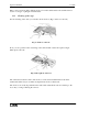
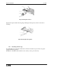
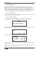
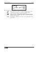
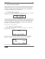
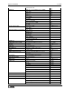
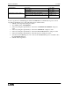
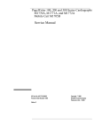
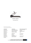
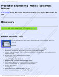
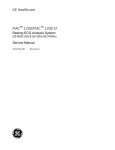
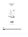
Operator Manual
Corival V3
English
Lode BV
Groningen, The Netherlands
0344
Operator manual
Corival
This is the short operator manual for the Lode Corival Ergometer, which describes the
basic actions for starting up your ergometer. For a complete description, we refer to our
User Guide.
Intended Use
A Lode ergometer is a diagnostic tool intended to be used as a stress test device in a medical
environment. The main goal of the use of a Lode ergometer is to create reproducible stress
tests. The following parameters can be measured:
Workload (watt)
Revolutions per minute (rpm)
Time (minutes and seconds)
Distance (km)
Optional: Blood Pressure (mmHg)
Optional: Heart rate (beats per minute)
Optional: Energy (KiloJoules)
Optional: SpO2
In combination with other diagnostic tools, like ECG or pulmonary function equipment, other
important physiological data can be obtained, allowing a physician to evaluate a test subjects
physical status.
A Lode ergometer is designed both for manual operation and for control by external ECG-,
pulmonary equipment. In combination with optional software, the ergometer can also be
controlled by a PC.
The ergometer has to be operated under the supervision of well-trained medical specialists,
like cardiologists, pulmonologists and physiotherapists. The ultimate judgment whether a test
subject should undertake a stress test with an ergometer and which protocols should be used
must be made by the responsible medical specialist, based on the limitations of each
individual, the medical history and all other applicable circumstances. Neither Lode BV nor
its distributors assume any responsibility for the final use of its equipment.
Contra Indication
The Corival ergometer is to be operated by classified personnel only. As stated in the intended
use, the Corival is intended to be used in a medical environment. During the intended use the
test subject will deliver energy. Application of the wrong dosis of energy could lead to
permanent damage of the test subject health.
Maintenance
The Corival should be calibrated once a year. In case any damage is observed of the Corival
Lode B.V. or his representative should be informed in order to execute the necessary
repair(s). Service of the Corival is restricted to factory-trained personnel only.
Precautions
Caution: This device should only be sold by, or on the order of authorized persons.
Operator manual
Corival
Caution: Not suitable for use in the presence of flammable anaesthetics.
Note: The voltage selector (115/230VAC) is inside the ergometer. The main unit panel has to
be unscrewed. Voltage selection should be done by a technician!
Possible hazards
Using the Corival according to intended use, contra indications, maintenance, precaution and
common sense stated above may not eliminate all hazards. Possible residual hazards could be:
wrong installation, wrong use, wrong dose, wrong interpretation of readings, mechanical
breakdown of parts, software failure.
LIST OF SYMBOLS USED
On/Off switch
External Input
External Output
Type B Electrical Safety
Separate collection of electric and electronic equipment
Copyright Lode BV, February 2008, All rights reserved.
Manufacturer information:
Lode BV
Zernikepark 16
NL-9747 AN Groningen,
The Netherlands
t: +31 50 571 28 11
f: +31 50 571-67 46
@: [email protected]
www.lode.nl
Operator manual
Corival
TABLE OF CONTENTS
1
DESCRIPTION OF THE CORIVAL ERGOMETER
1.1
1.2
1.3
MANUAL CONTROL QUICK START
ANALOG EXTERNAL CONTROL
TERMINAL – DIGITAL EXTERNAL CONTROL VIA RS232
2
MAIN MENU
3
SYSTEM PARAMETER
3.1
3.1.1
3.1.2
3.1.3
3.1.4
3.1.5
3.1.6
3.2
3.3
3.3.1
3.3.2
3.3.3
3.3.4
3.3.5
3.4
3.4.1
3.4.2
3.4.3
3.4.4
3.4.5
3.4.6
3.4.7
3.4.8
4
SPECIFICATIONS
4.1
4.2
5
TECHNICAL SPECIFICATIONS
FUSES
COMMUNICATION PORTS
5.1
5.2
5.3
5.4
A
SET DISPLAY
Power
RPM
Heartrate
Torque
Timer
Distance
SET P-SLOPE
SET MODE
Hyperbolic
HR controlled
Linear
Fixed Torque
Isokinetic (only available for Excalibur Sport 925900)
SETTINGS
Default Startmenu
Keyboard On/Off
Test Functions
P In/Out Analog
TC Bytes
RS232 Protocol
Language
Device No
RS232
LOOP CONNECTION
RS-232 SPECIFICATIONS
ANALOG IN/OUT
Maintenance
A.1
A.2
B
Cleaning
Replacing fuses
Programmable Display Unit 928810
B.1
Installing the Programmable Display Unit (option 928810)
B.2
Control panel Corival with Programmable Display Unit (option 928810)
B.3
Using the Programmable Display Unit
B.3.1
Menu structure programmable control unit
B.3.2
Manual menu
B.3.3
Analog menu
B.3.4
Terminal menu
B.3.5
System parameters menu
B.3.6
Operation from basic control panel
B.3.7
Protocol
C
Heart rate option 928924
C.1
Connecting the Heart rate system (option 928924)
6
7
8
8
9
10
10
10
10
10
10
10
10
10
11
11
11
11
11
11
11
11
12
12
12
12
12
12
12
13
13
13
14
14
14
14
14
15
15
15
16
16
16
16
17
18
18
19
19
20
21
27
27
Operator manual
C.2
C.3
D
Using the Heart rate option
Installing the BP cuff
Blood pressure option 928817, -818, 820
D.1
D.2
D.2.1
D.2.2
D.3
D.4
D.5
D.6
E
28
28
29
29
29
31
31
32
33
34
0 Watt Start-up System 906805
36
F.1
F.2
G
Using the BP system
Patient Hook-up
Apply the cuff
Position of the cuff
Abort codes BP system
Cleaning and disinfection
Cleaning of the cuff:
Installing the BP cuff
27
27
SpO2 option 928840
E.1
E.2
F
Corival
Precautions for Use
Using the SpO2 Option
Using the 0 Watt start-up system
0 Watt Start-up system with P-display
RS232 Connections
G.1
Overview
34
34
36
36
38
38
Operator manual
Corival
1 Description of the Corival ergometer
The control panel consists of the following elements:
1.
2.
3.
4.
5.
6.
Led indicator for rpm.
Display A directed to test subject.
Down button.
Up button.
Confirmation button.
Ergometer type indication.
Fig. 1 Control Panel standard Corival
The back panel of the Corival contains the following elements:
1.
2.
3.
4.
5.
6.
7.
8.
9.
Mains on/off switch
Mains connector
Fuse
Fuse
Dealer information label (if used)
RS232 in
RS232 out
Analog i/o
Protective Earth connector
Fig. 2 Back panel connections
6
Operator manual
Corival
Adjustability
The ergometer is adjustable to test subjects of most sizes and ages.
• The height of the saddle can be adjusted by tilting the handle on the back underneath the
saddle
• The height of the handlebars can be adjusted by loosening the handle in front of the
ergometer.
Moving the ergometer
The ergometer can be moved by turning it over to the right (appr. 30º) when you are in front
of the handlebar. A wheel in the middle of the ergometer drops out. You can now drive the
ergometer to its location. Turn it over to the left (appr. 30º) and the wheel in the middle will
fold in. The ergometer is ready for use.
Instructions for installing the Corival ergometer
1.
Place the ergometer in the location where it will be used.
2.
Check (at your supplier) whether the voltage set for the ergometer is set correct.
3.
Connect the power cord first to the socket of the ergometer and then connect it to the
line voltage.
4.
Switch the power switch on. The indicator lamp in the switch lights up.
If the initialisation screen with the software version will appear for a few seconds, the
ergometer is ready for use.
1.1
Manual control quick start
If the Corival is switched on, the default startup menu is the entrance to the MAIN MENU.
Press the confirmation button ( ) to enter the main menu. Select with the arrow keys ▼▲ the
MANUAL MODE. Press ( ) and you will see the following screen:
P=
0W
0 rpm
MANUAL
With the ▼▲ keys the workload can be in- or decreased. The workload will rise with 25
watt/sec when the rpm is above 30. Keeping the ( ) pressed for a few seconds allows you to go
up one or more menu levels.
During cycling, the display shows the following information:
• the top line shows 1 or more ergometry parameters.
• the bottom right corner shows the current control mode.
• at the bottom left position the selected adjustable parameter is shown.
7
Operator manual
1.2
Corival
Analog external control
Execute the following steps to control the Corival externally using the analog in-/output:
1.
Connect the external controling device (e.g. ECG system) with a correct cable to the
analog i/o port.
2.
Start the ergometer and go in the main menu to ANALOG.
3.
Now the ergometer can be controlled by an external device with an analog signal.
1.3
Terminal – digital external control via RS232
For digital external control using the RS232 serial port execute the following steps for the
basic Corival:
1.
Connect the Corival to the external control device (i.e. ECG system, PC) using a
correct RS232 cable
2.
Switch on the ergometer and select the menu TERMINAL on the display.
3.
Be sure that the correct protocol has been selected under the menu SYSTEM
PARAMETERS / SETTINGS / RS232 PROTOCOL
For a list of available protocols and ECG system, we refer to the user guide or your local
dealer. If you usually control your ergometer from an ECG system in the TERMINAL
MODE, you can set this mode as default startup menu. The Corival is now ready for digital
external control. Another option to control the ergometer from a pc is with the Lode
Ergometry Manager (LEM, article 92890X) software. This uses the Lode 38k4 protocol.
8
Operator manual
Corival
2 Main menu
When the ergometer is started after pressing the confirmation button ( ) you enter the MAIN
MENU. The following submenus are selectable from the main menu:
!
TERMINAL
!
MANUAL
!
ANALOG
!
SYSTEM PARAMETER
Use the arrow keys▼▲ to scroll through the menus. Press the ( ) button to select a menu.
Keeping the ( ) pressed for a few seconds allows you to go up one or more menu levels,
wherever you are in the menu. The complete menu structure is shown below. In front of each
menu the level depth is indicated.
0. MAIN MENU
1. ANALOG
1. MANUAL
1. TERMINAL
1. SYSTEM PARAMETER
2. SET DISPLAY
3. POWER
3. RPM
3. HEARTRATE
3. TORQUE
3. TIMER
3. DISTANCE
2. SET P-SLOPE
2. SET MODE
3. HYPERBOLIC
3. HR CONTROLLED
3. LINEAR
3. FIXED TORQUE
3. ISOKINETIC (only available for Excalibur Sport 925900)
2. SETTINGS
3. DEFAULT STARTMENU
3. KEYBOARD ON/OFF
3. TEST FUNCTIONS
3. P IN/OUT ANALOG
3. ECG TRIGGER
3. TC_BYTES
3. RS232 PROTOCOL
3. LANGUAGE
3. DEVICE NO
3. SEATING POSITION (only available for Excalibur Sport 925900)
9
Operator manual
Corival
3 System parameter
In the System Parameters different specific ergometer settings can be carried out.
3.1
Set display
This function allows you to adjust the parameters which can be read out on the display during
exercising. If more then 2 are set to ON they are shown in groups of 2 scrolling. Choosing
default allows you to go to factory settings for the display parameters.
Press the ( ) button to go to the next parameter and switching the actual parameter ON/OFF is
done with ▼▲ keys.
3.1.1
Power
Power indication in watts can be switched ON or OFF using the ▼▲ keys. The power
displayed is the actual power of the brake. This means that regulation speed is incorporated.
When rpm drops below 25 rpm the load is removed at once, because the pedal torque
becomes very high. Load is put on the brake when rpm is greater or equal to 30 rpm.
3.1.2
RPM
Switch ON or OFF the Cadence readout in Revolutions per minute. The rpm can always be
read out by the LED bar graph on top of the display independent of this adjustment.
3.1.3
Heartrate
Switch ON or OFF the Heart rate indication in beats per minute. The ♥ symbol is used in the
display.
3.1.4
Torque
Switch ON or OFF the Torque in the readout. The Torque is displayed in Newton meter.
3.1.5
Timer
Switches the Timer ON or OFF in the readout. The timer is shown in the display as: Θ =
mm:ss. The timer starts when you enter manual, terminal or analog mode and the rpm
increases above 30. The timer is reset when one of these modes is left.
3.1.6
Distance
Switches the distance ON or OFF. The distance is shown in the display as: → = 99,9 km,
expressing the distance in km. A fictive formula is used (see main manual), holding only for
average cycle conditions and it should not be used for diagnostic purposes.
3.2
Set P-slope
The load regulation steepness is set by this parameter to the default norm-value of 25 watt/sec
or to maximal. During the Wingate sprint test the P-slope has to be unlimited.
10
Operator manual
3.3
Corival
Set mode
Set mode is used to define which parameter (like load, torque, heart rate and linear constant
alpha) has to be adjusted during exercising in MANUAL mode with▼▲ keys
3.3.1
Hyperbolic
Hyperbolic mode means that the load P can be adjusted in watt. The load is kept constant
independent of rpm.
3.3.2
HR controlled
Heart rate can be adjusted and the load is regulated until the adjusted heart rate is reached.
This means when heart rate increases above the adjusted level load is decreased and the other
way around.
3.3.3
Linear
In linear mode the load P is coupled with rpm using the following formula:
P [W] = α* (n [min-1] )2
The linear coupling constant α is the adjustable parameter in this case.
3.3.4
Fixed Torque
In Fixed Torque mode the load is regulated such that the torque is kept at a set fixed value,
according to the formula:
T [Nm] = (P*60) / ( 2 * π * n [min-1])
Note: be aware of the fact that this fixed torque mode is not the same as the constant Torque
mode which is used with the Wingate software module (see for more information the Wingate
manual).
3.3.5
Isokinetic (only available for Excalibur Sport 925900)
In the Isokinetic mode the rpm is kept constant during the exercise, according to the formula:
-1
P [W] = ( 2 * π * n [min ]*T [Nm]) / 60
During the exercise you can not pedal faster then the chosen rpm. You can deliver more Force
with the same speed and produce more workload in this way.
Note: The rpm is the adjustable parameter in this case, this mode can be used to define the
optimal rpm.
3.4
Settings
Under settings all device specific and interface adjustments can be made. It concerns to all
those items not related directly to ergometry.
3.4.1
Default Startmenu
Normally your ergometer starts in the main menu. But you can modify this menu to your own
desired settings. This is convenient when your ergometer is used often in the same setting,
The following menus can be selected as startmenu: MAIN MENU; MANUAL; TERMINAL;
ANALOG At the next startup of your ergometer the selected menu will be activated.
11
Operator manual
3.4.2
Corival
Keyboard On/Off
If you do not want to interrupt a training or you do not want the test subject to interrupt the
training by pressing a key accidentally, the possibility is offered to disable the keyboard
Now you wonder how to get back the control to the keyboard. Act as follows:
Switch off the ergometer
Switch it on again while keeping the ( ) button pressed. Now you have back the control. Go to
SYSTEM PARAMETERS / KEYBOARD ON/OFF and set it to ON.
At the next startup of the ergometer the keyboard is enabled again.
3.4.3
Test Functions
For servicing and calibration of the device a number of diagnostic tools is available in the
software. They are hidden under Test functions. You need a safety code to enter the
TESTFUNCTIONS.
3.4.4
P In/Out Analog
The ergometer can be controlled by an external device which has an analog output only. This
is done using the ANALOG mode. With P In/out Analog the analog scaling can be adjusted:
- 1 V analog in - can correspond with a workload of 100 W / 200 W / 500 W.
3.4.5
TC Bytes
The Test code (TC) Bytes offer in case of malfunction or poor performance of the BP option
the possibility to make error codes visible. Your local distributor can help you diagnose the
problem with the Error Code.
3.4.6
RS232 Protocol
When the ergometer is externally controlled via RS232 a protocol should be selected here.
3.4.7
Language
You can choose different languages for the ergometer.
3.4.8
Device No
When RS232 communication is used with the ergometer, it is identified with a so called
device number. This offers the possibility of looping through ergometers.
12
Operator manual
Corival
4 Specifications
4.1
Technical Specifications
Principle
Mains voltage
Frequency
Patient capacity
Power consumption
Workload
Device control
Accuracy
:
:
:
:
:
:
:
:
Read-out workload
Read-out pedalling speed
:
:
eddy current brake small disk.
115-230 VAC (adjustable)
50 Hz, 60 Hz.
350 lb - 160 kg.
120 VA.
0-999 W HYP, 0-999 W LIN
manual, external analog, external digital
< 3 W for P <= 100 W, < 3% for 100 W<
P<500W, <5% for P>500 W.
digital, 0-999 resolution 1 W.
analog 0-180 rpm or digital 0-255.
Output workload
Output pedalling speed
Input voltage for external control
:
:
:
100, 200 or 500 W
100 min-1 1 V.
100,200 or 500 W
Safety class Corival
Safety class Corival + BP option
:
:
I type B, IEC 601-1 chapter 18, 19 and 20.
IIa type B, IEC 601-1 chapter 18, 19 and 20.
Leakage current
Isolation resistance
Earthway resistance
:
:
:
< 0.4 mA.
> 4 MΩ.
< 0.2 Ω.
Zero load
Noise level
:
:
< 8 W at 60 rpm.
+/- 60dB at workload 200W/60rpm +/-80cm from
crank.
4.2
115 V
230 V
1 V (max. 999 W).
1 V (max. 999 W).
Fuses
:
:
2 x 1,60 A slow.
2 x 0,80 A slow.
13
Met opmaak:
opsommingstekens en
nummering
Operator manual
5
Corival
Communication ports
This chapter describes the communication ports in the main unit panel of the Corival:
! RS232 (two ports for RS232-in and loop connection RS232-out)
! Analog in/out
5.1
RS232
The Corival has two RS232 connectors for loop-connecting a number of Corival’s and for
communication with a personal computer or an ECG device. When the ergometer is
controlled externally always use the RS232-in port.
Via RS232 an ergometer can be monitored and settings can be entered with a computer. See
main manual for App E for protocols and cabling for your controlling device and the Pin
layout RS232 connector
5.2
Loop connection
It is possible to control several Corival ergometers with one external device using RS232.
Connect the RS232-in connector to the external device. Connect the RS232-out connector to
the RS232-in connector of the following Corival ergometer, and so on. The maximum number
of Corival ergometers that can be connected in this way is 8. Use the device number option in
SYSTEM PARAMETERS to give each Corival a unique number. In this way each Corival
can be controlled separately, using the LEM software.
5.3
RS-232 specifications
See main manual for detailed information
5.4
Analog in/out
This connector can be used to connect the Corival to other analog controlling instruments. See
main Manual for detailed information.
14
Operator manual
A
Corival
Maintenance
The Lode Ergometer is mechanically and electronically designed for durability and accuracy.
This also accounts for the options and add-ons of the device. The frequency of calibration
depends on the intensity of usage. As a rule Lode Ergometers are calibrated on an annual
basis. Please refer to the Service Manual for specific details on check-up intervals for the
Lode Ergometer and its options and/or add-ons.
The dynamic calibration is performed using calibration equipment specially designed by the
manufacturer.
A.1
Cleaning
The housing of the Corival ergometer and all other external surfaces can be cleaned with a
cloth dampened with non-aggressive liquid.
A.2
Replacing fuses
You will not need a certified technician to replace fuses of the Corival.
Always disconnect the power cord first!
Unplug the mains cable. The fuses are part of the main unit (Fig. 3 Main unit panel
connections, item 8) and located at the bottom of the main unit. You have to lift the Corival
place it in the upright position (90°) to locate the fuses. Unscrew the fuse holders with a
screwdriver, replace the broken one and place them back again. Note: make sure that the fuses
that are in the Corival match the set voltage (115 V: 2 x 1,25 A slow; 230 V :2 x 0,63 A
slow).
Contact your local dealer for a maintenance contract or ask Lode:
LODE BV
Service department
Zernikepark 16
9747 AN Groningen
The Netherlands
Tel. +31 50 5712811
Fax. +31 50 5716746
Email: [email protected]
Internet: www.lode.nl
15
Operator manual
B
Corival
Programmable Display Unit 928810
B.1
Installing the Programmable Display Unit (option 928810)
When the option 928810 is ordered later on, it should replace the standard Control Unit.
Replacement should be carried out by service personnel only. For the description, we refer to
our user guide supplied with this ergometer.
B.2
Control panel Corival with Programmable Display Unit (option 928810)
1.
2.
3.
4.
5.
6.
Display B (4x20 characters) directed to
operator
Infrared window (only active for option
928820)
One-step-back button
Down button
Up button
Confirmation button
Fig 1: Control Panel with Programmable Display Unit
B.3
Using the Programmable Display Unit
Check if the ergometer is properly installed.
In the display of the basic control panel the following appears for a few seconds:
LODE ERGOMETER
TBD
Followed after a few seconds by:
P=
0W
0 rpm
At the same time the programmable control panel shows for a few seconds:
16
Operator manual
Corival
LODE
P-display
ver X.YZ
In case the Blood pressure option is available it is followed for approximately 1 second by the
text "BPM Initialized "thereby indicating correct operation of the BP device. The SpO2 comes
together with the P-Display. When this option is available correct operation is indicated by
the text "SpO2 Initialized" In case the 0-Watt Start -up System is available the text "0 Watt
Initialized" is displayed indicating the 0-Watt Start -up System is detected
When all three options are installed the display shows:
LODE
BPM Initialized
SpO2 Initialized
0 Watt Initialized
Then the main menu appears:
system parameter
TERMINAL
manual
Term
The menu displayed in capitals can be selected. As extra reminder the first 4 letters of the
selectable mode are showed above the confirmation button. With the ▼▲ keys you can scroll
through the other menus and select SYSTEM PARAMETERS, MANUAL, ANALOG or
PROTOCOL. With the right ( ) confirmation button the menu in capital can be selected. The
left ( ) escape button is used to go back one level in the menu structure.
The ergometer is now ready for use. If nothing appears in the display(s), check whether the
power cord and the control unit have been properly connected or contact your supplier.
B.3.1 Menu structure programmable control unit
0. MAIN MENU
1. ANALOG
1. MANUAL
1. TERMINAL
1. SYSTEM PARAMETER
2. SET DISPLAY
3. POWER
3. RPM
3. HEARTRATE
3. TORQUE
17
Operator manual
Corival
3. TIMER
3. DISTANCE
3. TARGET HR*
3. ENERGY*
2. SET P-SLOPE
2. SET MODE
3. HYPERBOLIC
3. HR CONTROLLED
3. LINEAR
3. FIXED TORQUE
3. ISOKINETIC (only available for Excalibur Sport 925900)
2. SETTINGS
3. DEFAULT STARTMENU
3. ECG START*
3. P IN/OUT ANALOG
3. CONTRAST
3. ECG TRIGGER
3. TC_BYTES
3. RS232 PROTOCOL
3. LANGUAGE
3. DEVICE NO
3. SEATING POSITION (only available for Excalibur Sport 925900)
1. PROTOCOL*
2. PROTOCOL EDIT *
2. PROTOCOL RUN *
3. ÅSTRAND PROTOCOL*
2. PROTOCOL DELETE *
Compared to the standard version the *menus are added.
B.3.2 Manual menu
Selecting the manual mode will show you (default) the following display at the programmable
control panel:
MANUAL
P = 0W
♥ = 0/m*
esc
0 rpm
P
BPM*
* BPM is displayed when this option is available, otherwise another MENU possibility is
active. With the ▼▲ keys you can increase or decrease the parameter of the selected mode.
In the middle the adjustable parameter is shown, f.i. the load P (to be set with SYSTEM
PARAMETERS> SET MODE)
B.3.3 Analog menu
Selecting the ANALOG menu will show the following screen at the programmable panel:
ANALOG
P = 0W
♥ = 0/m*
esc
0 rpm
esc
18
Operator manual
Corival
Notice: ♥ = 0/m* Only displayed if HR option is being installed!
The ergometer is now ready for external control with an analog signal as previously
described. See for more information about analog control the user guide (only available in
English) supplied with the ergometer.
B.3.4 Terminal menu
Selecting the TERMINAL menu will show the following screen at the programmable panel:
TERMINAL
P = 0W
♥ = 0/m*
esc
0 rpm
esc
Notice: ♥ = 0/m* Only displayed if HR option is being installed!
The ergometer is now ready for digital external control. For more information about digital
external control using the RS 232 serial port see the user guide supplied with the ergometer.
B.3.5 System parameters menu
In the SYSTEM PARAMETERS different ergometry specific settings can be carried out as
described previously in the standard manual. On the programmable control panel you can
select the desired menu:
set p slope
SET DISPLAY
settings
syst
set
The menu displayed in capitals and repeated with an abbreviation under the confirmation
button ( ) is the one which can be activated. Selecting one of these menus will show you a
more extended display then described previously in this manual. As you can see with the
example of SET DISPLAY:
POWER
On
esc
off
on
next
19
Operator manual
Corival
Where the function POWER is the same as described previously in this manual (power
indication on or off), the button ESC will bring you back to the system parameters menu.
With the ▼▲ keys you can select the power indication to be ON or OFF, and NEXT will
bring you to the next item of the SET DISPLAY menu. Beside the parameters RPM, HEART
RATE, TORQUE, TIMER and DISTANCE two more are parameters are added: TARGET
HEART RATE and ENERGY.
Selecting the target HR parameter will show you the target heart rate programmed in the heart
rate controlled protocol beside the actual heart rate. For instance:
2 t=00:48
θ=01:12
P= 23 W
61 rpm
♥= 91/min t♥=100/min
rec
rec
Selecting the energy parameter will show you the total amount of mechanical energy
delivered by the test subject going into the ergometer in the form of mechanical motion,
during the exercise test.
Instead of 2 items you can show 4 items out of your selection at once, they will scroll in
groups of 2. When you select 4 parameters, there will be no scrolling but a fixation on the
display of these parameters. You can program the parameters (also up to 4 without scrolling)
at the basic control panel as well, but you have to switch the control over to the basic side first
as is described in the next paragraph.
The menu SETTINGS will give you the opportunity to select PROTOCOL as a default
startmenu besides the previously described menus ANALOG, MANUAL, TERMINAL and
SYSTEM PARAMETERS.
An extra option for the Programmable control unit in the menu SETTINGS is the
CONTRAST adjustment for the P-display. Adjusting contrast shows direct effect on the
display. Only after confirmation with SAVE the new contrast is kept!
B.3.6 Operation from basic control panel
With the basic control panel as described previously in this manual you had the possibility to
switch your KEYBOARD ON or OFF. With the programmable control panel the basic (test
subject) side of the unit is default OFF. It is possible to control the ergometer with the buttons
of the basic control panel instead of the programmable control panel. You can use this option
for service purposes or to program the display of the basic control panel. During the startup of
the ergometer you can press one of the buttons at the basic side to switch operation to this
basic control panel, you will then loose the control function of the programmable side. To go
back to the default control situation you have to restart the ergometer without pressing any
button.
The TEST FUNCTIONS are only available at the basic control panel. They are meant for
service personnel only. Contact your supplier in case service of the device is required. If,
20
Operator manual
Corival
accidentally, you get into to the TEST FUNCTIONS it can cause damage to the
ergometer operation and guarantee will be lost!
B.3.7 Protocol
In this paragraph the program possibilities under the menu PROTOCOL will be described:
protocol run
PROTOCOL EDIT
protocol delete
prot
edit
You can select the menus PROTOCOL EDIT; PROTOCOL RUN and PROTOCOL
DELETE.
B.3.7.1
Protocol edit
The menu PROTOCOL EDIT allows you to program new exercise protocols or edit an
existing protocol. The memory capacity will allow you to save 50 protocols, all existing of
maximal 15 steps each. Pressing this menu will show you the list of protocols which have
already been made and the menu NEW.
New
name1
name2
esc
ok
With the ▼▲ keys you can select the desired protocol (in this example name1) to edit. Select
NEW to program a new exercise protocol and give the protocol a useful name maximal 10
characters with the▼▲ keys. The allowed characters for the name are: ‘0’..’9’,’a’..’z’,
and ’ ’. Move the cursor with the confirmation button ( ) OK to the 10th position and the
program screen will appear:
Name 1
Step P= 0W t=00:00
1S dP=+050W dt=060s
esc
next
On top the protocol name is mentioned. The second line will give you information about the
status of the programmed momentary workload (P) and time (t). The third line is the actual
program line. The stage number with the type of stage is mentioned, followed by the
programmable parameters (workload in the above example) and time. Those parameters are
displayed as ∆ Power (dP) and ∆ time (dt). ∆P is the change in power expressed in watts. ∆ t
is the change in time expressed in seconds. The underlined character is the item which can be
21
Operator manual
Corival
changed, in the example mentioned above: S. Pressing the ▼▲ keys give you the ability to
toggle between the possibilities for programming a stage in a protocol: S, T, L, H, P and
Recovery.
the workload can be adjusted + or – and the duration of this hyperbolic
stage can be determined; the load is independent of the RPM.
T= torque
fixed torque: the torque in Nm can be adjusted with certain duration.
L= linear
the workload is coupled with RPM with constant α as the adjustable
parameter for the desired duration; load P = α * N2 [W] goes up with
square of cadence.
H= heart rate
the workload is regulated as a function of the adjustable heart rate for a
certain duration in this heart rate controlled step.
P= proportional the workload is increased linear as a function of time (ramp protocol). It
will take the total duration time to reach the programmed workload;
R = Repeat
repeat steps (until max. workload): you have to enter the workload step and
the duration of the step only once.
Recovery
the recovery stage is the last stage of a protocol with a fixed workload and
an unlimited duration (only 1 recovery stage in 1 protocol)
S= step
After the confirmation of the workload during the recovery stage the menu PROGRAM BPM
will appear. Toggle with the ▼▲ keys for the measurement possibilities:
No BPM
Repeat
EOS
no BPM module available, select this option when the BPM is not installed, or
no automatic blood pressure measurement during this protocol;
allows you to program a repeat time in minutes during the exercise stages:
End Of Stage; automatic measurement at every end of the exercise step with
the possibility to program the measurement time before the end of the stage.
Recovery time If you have programmed automatic BP measurement in the protocol, you get
the possibility to program the repeat time of the BP measurement during the recovery stage:
After the programming of the BPM the menu PROTOCOL will appear again. You can RUN
EDIT or DELETE one of the protocols now.
B.3.7.2
Example Programming Protocol
For the purpose of clarification we will program a demonstration protocol with all
possibilities. Execute the following steps to get into the programming mode.
1.
2.
3.
4.
5.
6.
Select PROTOCOL in the MAIN MENU, confirm ( )
Select PROTOCOL edit, confirm ( )
Select New, confirm ( )
Give a protocol name: test
With the ▼▲ keys you can scroll through the alphabet confirm, use next ( ) to go to
the next position
The program screen appears, the underscore showing the programming parameter:
22
Operator manual
Corival
test
Step P= 0W t=00:00
1S dP=+050W dt=060s
esc
next
Confirm the S with ( ), use the ▼ key to decrease the workload to 10 watt.
7.
Press the confirmation button NEXT until you reach the following screen. Adjust time
dt to 60 seconds using the ▼▲ keys.
test
Torq P= 10W t=01:00
2T T= 10Nm dt=030s
back
next
8.
9.
10.
11.
12.
Select T with the ▼▲ keys and adjust the Torque to 10 Nm and the duration to 30
seconds with the same keys. Press the confirmation button.
Select L with the ▼▲ keys and confirm the constant α =0.041, change the duration to
10 seconds. Press the confirmation button.
Select H with the ▼▲ keys and change the heart rate in 120/m for a duration of 180
seconds, press the confirmation button.
Select P with the ▼▲ keys and change the Workload to 150 in duration of 300
seconds, press the confirmation button.
Select P with the ▼▲ keys and change the Workload to minus 60 in 60 seconds, press
the confirmation button.
test
Ramp P=160W t=09:40
6P dP=-060W dt=060s
back
next
13.
14.
15.
Select Recovery the ▼▲ keys and change the Workload to 35 and press the
confirmation button.
After confirmation you will automatically go to the BPM menu.
Select No BPM when the BPM module is not installed or select Repeat with the ▼▲
keys and choose 2 minutes for the repeat time, confirm with ( ) and choose 2 minutes
for the repeat time in the recovery stage. The protocol TEST (with BPM) is ready
now, you can go to protocol RUN to test this special protocol (not for normal use).
To edit an existing protocol, you have to select the desired protocol first. You can change the
name or confirm the name with OK ( ) ten times. Now you can walk through the stages with
the confirmation button, until you reach the stage you want to edit. You have to scroll through
23
Operator manual
Corival
the total protocol and define the recovery stage before you leave this menu otherwise the
changes will not be saved.
B.3.7.3
Protocol Run
The menu PROTOCOL RUN is used to select the desired protocol for the exercise test. Select
Protocol Run and three previously programmed protocols will appear on screen. To scroll
through the total list use the arrows, for instance:
10w min
25w 2 min
ramp 400w
esc
ok
If you want to select e.g. the protocol 10 w min, use the ▼key until a space appears in front of
the name of the protocol (the selectable item is always on the 2nd line) and confirm with ok.
The following message will appear on screen:
10w min
1 P=0W t=00:00
1S dP=+10W dt=060s
esc
ok
This screen is used to check the selected protocol; in this case the name is 10w min: the first
step will start with 10 watt for 1 minute. Press the confirmation button to go on:
10w min
start at 30 rpm
n= 0/min
esc
ok
The ergometer is ready for use with the selected protocol. When the test subject exceeds the
30 rpm the protocol will run. You will see the following screen:
24
Operator manual
Corival
1 t=00:59
P= 10 W
♥ = 83/min
rec
θ=00:01
58 rpm
rec
In this example the screen shows that this is the first stage, t= 00:59 with 59 sec to go, the
timer is showing 1 sec of total exercise time, the timer will stop the registration when the
RPM drops below 30. The workload P is 10 watt, the pedaling frequency is 58 RPM, and the
heart rate is 83 beats per minute. The three displayed parameters are those selected under
SYSTEM PARAMETERS / SET DISPLAY. At the bottom line you will find the recovery
button on the left and right which will bring the workload immediately to the programmed
recovery workload. In case the optional BPM is installed you will find instead of the right
recovery button a BPM button which allow you to measure the blood pressure with the
optional automatic blood pressure module (see the appendix concerning Blood pressure in this
manual).
The next steps will automatically follow. With the ▼▲ buttons you can go the next stage or
previous stage when you do not want to follow the protocol as programmed.
B.3.7.4
Blood Pressure Measurement
When your controller is extended with the optional automatic blood pressure module you can
either program a measurement interval (see Protocol edit B.3.7.1 and Example Programming
Protocol B.3.7.2) or press the ( ) BP button (see appendix on BP measurement) to start
manual a BP measurement. You will see the selected display parameters.
BPM
P= 30W
60 rpm
♥ = 114/min
protoc dis ► proto
Pressing PROT (protocol) will bring you back to the normal exercise protocol screen.
Pressing DISP (▼▲) will allow you to toggle between the BP parameters and de default
selected parameters. START will start the blood pressure measurement.
Pressing DISP again will show as next display the actual pressure p.
BPM
p = 123 mmHg ♥ ♪
P= 30W
60 rpm
protoc dis ► proto
Whenever the test subject is allowed to or has to stop the exercise test, the recovery button has
to be pressed. The following will appear on screen:
25
Operator manual
Corival
Rec P= 50W
P= 50W
♥ = 174/min
esc
t=10:30
60 rpm
esc
In this example the recovery phase will bring the workload down to 50 watt. The timer is
showing 10:30 seconds and will go on with the registration during the recovery as long as the
RPM is above 30 (the BPM can still be measured when BPM is displayed at the confirmation
button). To stop the recovery phase press the ESC button to go back to the PROTOCOL
menu. In the menus MANUAL, TERMINAL or ANALOG the BP function is the same as
described above.
B.3.7.5
Protocol delete
This function allows you to delete a protocol. Select the protocol which you do want to
remove (in this example TESTPROTOCOL) and confirm with OK. The following screen will
appear:
testprotocol
Delete?
esc
ok
Confirm with OK when you agree and the message [deleted] will appear on the screen.
26
Operator manual
C
Corival
Heart rate option 928924
C.1
Connecting the Heart rate system (option 928924)
To install a heart rate option purchased afterwards, follow the instructions given in the user
guide supplied with the ergometer. Installation of the Heart rate option itself has to be done by
service personnel only.
C.2
Using the Heart rate option
The heart rate option is automatically recognized by the ergometer. The Polar belt should be
mounted around the chest of the test subjects (at heart level) with Polar trade mark pointing
forwards from the middle of the chest. The belt should not be to loose. If you have a weak
signal, check following tips:
• Wet the contacts on the right and left backside of the Polar belt for good contact
• Stay near the receiver (within a range of 0.8 meter) which is located in the display unit
at the test subjects side below the readout.
• Due to the integration measurement principle it can take a few seconds before the
readout on the display shows the correct value. Be patient.
• The test subject should be positioned in such way that a straight virtual line can be
drawn between the Polar trade mark on the belt and the receiver inside the display
unit, or placed in front of the Test subject
C.3
Installing the BP cuff
To install a B option purchased afterwards, follow the instructions given in the user guide
supplied with the ergometer.
Installation of the Blood pressure measurement module itself has to be done by service
personnel only.
27
Operator manual
D
Corival
Blood pressure option 928817, -818, 820
With option 928817, -818, 820 it is possible to perform stand alone or external controlled
blood pressure measurements. After installation the BP module is recognized automatically at
start up of the ergometer, indicated by the following screen for a few seconds:
LODE ERGOMETER
TBD
D.1
Using the BP system
Caution: Carefully read the instructions in Appendix D.2 Patient Hook-up before continuing.
Only well trained medical personnel, familiar with BP measurement, should operate the BP
system.
When you are in the MANUAL, TERMINAL or ANALOG mode you can go to the BP
measurement by pressing ( ) button. The following menu appears:
P= 90W
dis ►
69 rpm
MANUAL
In the upper line of the display still your selected readout parameters appear. The buttons
below have the following functions:
▼
dis: Toggle the display between your readout parameters and the pressure p [mm
Hg]. Pressure is indicated as lower case p and workload with upper case P.
P =
dis
▲
►:
0 mm Hg
►
MANUAL
The BP measurement starts:
P = 120 mm Hg
dis █
MANUAL
With the same button the BP can be aborted at any time and the pressure will be released.
()
MAN / TERM / ANA: Return to the operation mode where you started from
(MANUAL, TERMINAL or ANALOG).
During the first BP measurement of the test subject the cuff inflates to 180 mm Hg. For each
subsequent BP measurement, the last measured SYSTOLIC value +50 mm Hg is used as a
maximum inflation limit. Be aware that in case of an error (D.3) the inflate limit can go up to
260 mmHg worst case. Above 300 mm Hg, or if a measurement lasts longer than 180
seconds, the hardware releases pressure immediately for safety reasons. Deflation is done 40
28
Operator manual
Corival
mm Hg below the last measured DIASTOLIC pressure. The used deflate rate is
approximately 4 mm Hg/heartbeat.
A list of most occurring warnings and errors is given in D.3 Abort codes BP system.
The built-in BP module offers, in case of malfunction or poor performance, the possibility to
make error codes visible. See for more information the user guide supplied with this
ergometer.
Caution: The interpretation of the error codes should be done only by experts. Ask your
supplier for more information.
D.2
Patient Hook-up
Correct patient hook-up is very important. Experience has shown that a lot of troubles can be
avoided when the rules below are kept in mind. Especially BP measurement using Korotkoff
tones under stress requires accurate preparation.
D.2.1 Apply the cuff
On the inside of the upper arm you can feel the brachial artery. Palpate the brachial artery to
ensure proper placement. The best place for the microphone is where you can most clearly
feel the pulse (Fig 2: Palpating the arm). Upper clothing should be taken off!
Pulled up garments should not jam the upper arm.
Fig 2: Palpating the arm
D.2.2 Position of the cuff
The cuff should be placed on the upper arm, so that it is positioned about 2 cm above the
elbow close to the heart level (Fig 3: Cuff position). Place the microphone on the position that
you palpated.
29
Operator manual
Corival
Fig 3: Cuff position
Caution: Never place the cuff so that the microphone is located in the elbow.
Pull the cuff so tight, that it neither moves nor ties off the arm of the patient. By fasten the
cuff too tight or too loose, error measurements are caused.
Wrap the end of the cuff around the upper arm and close the Velcro fastening (Fig 4:
Mounting the cuff).
Fig 4: Mounting the cuff
Ensure that the air hose from the monitor to the cuff is not compressed, crimped or damaged.
During ergometry the air hose should be handled and attached in such a way, that vibrations
and movement artefacts are avoided. Use the ring strap to fix the tubes to the wrist to avoid
tensions on the cuff due to moving and pulling tubes.
During the measurement, which starts with inflation, the arm with the cuff should be
kept in rest. With ergometry it is most convenient for the patient to take the arm from the
handlebar of the ergometer and relax the arm with the cuff.
30
Operator manual
Corival
The intervals of the measurements should not be too short. Intervals of 2 minutes and more
result in long pauses between the stenoses, so that venous congestion and artiospasm can be
avoided.
D.3
Prior.
Abort codes BP system
Error message
Display
Possible error cause
1
ACHECK ECG
SIGNAL@@
0 / 0 mmHg
!
!
!
!
2
ACUFF
OVERPRESSURE@@
0 / 0 mmHg
! Strong arm movements during the blood
pressure measurement.
! Air hose is bent or blocked.
3
AAIR LEAK@@
0 / 0 mmHg
! Cuff is loose or not connected.
! Air hose or air-bubble leak.
! Air hose not connected.
4
ASERVICE
REQUIRED@@
BP
value
! Fatal error ...Get in touch with the company
Lode.
5
ACHECK ECG/
MICROPHONE@@
BP
value
! Poor patient hook-up (irregular ECG-signal) or
poor trigger signal.
ECG trigger not connected.
ECG trigger properties not correct.
ECG trigger polarity not correct.
QRS pulse width smaller than 10 ms.
AND
! Abnormal microphone-signal or damaged
microphone.
6
ACHECK
MICROPHONE@@
BP
value
! Wrong Microphone placement or defect
microphone.
7
ACHECK ECG/
ARTIFACT@@
BP
value
! ECG trigger signal failed during blood pressure
measurement.
Bad or irregular ECG-signal during the blood
pressure measurement.
AND
! Excessive movements of the patient during the
blood pressure measurement.
8
AARTIFACT/ARM
MOVEMENT@@
BP
value
! Excessive movements of the patient during the
blood pressure measurement.
9
ACUFF INFLATION
TOO LOW@@
BP
value
! Maximum cuff pressure adjusted too low.
! Inflation pressure adjusted too low. Repeat
measurement.
10
None
BP
value
D.4
Cleaning and disinfection
31
Operator manual
Corival
Entry- and connection cables, like the air-hose from the cuff should not be sterilized in hot
steam or cold gas or plunged in disinfectants.
D.5
Cleaning of the cuff:
For the cleaning of the cuff, you can take out the air-hose (Fig 5: Air-hose removal).
Fig 5: Air-hose removal
Now you can open the Velcro fastening of the cuff and take out the microphone, Fig 6:
Microphone removal.
Fig 6: Microphone removal
The cuff can be washed at 30° C. The air-hose can be cleaned with mild non-alcoholic
disinfectant. There may not remain any liquid in the air-hose afterwards.
The air-hose can easily be put back in the cuff, if beforehand both ends are rolled up to the
hose entry, see Fig 7: Placing the air-hose.
32
Operator manual
Corival
Fig 7: Placing the air-hose
Slip the microphone back in the bag (Fig 8: Placing the microphone) and close the Velcro
fastening.
Fig 8: Placing the microphone
D.6
Installing the BP cuff
To install a BP option purchased afterwards, follow the instructions given in the user guide
supplied with the ergometer.
Installation of the BP module itself has to be done by service personnel only.
33
Operator manual
E
Corival
SpO2 option 928840
With option 928840 your Corival is able to perform stand alone or external controlled
measurement of functional oxygen saturation of arterial hemoglobin (%SpO2) and pulse rate
(BPM) for adult and pediatric test subjects. Keep in mind the fact that SpO2 measurements
during arm exercise is not possible due to movement artifacts. Do not attach the pulse
oximeter to the same limb as the Cuff of the blood pressure monitor or any other blood flow
restrictor. Loss of monitoring can occur due to the hindering of pulse measurement.
E.1
Precautions for Use
In the User Guide for your Corival Contraindications, Warnings and Cautions are stated. The
user should have knowledge of this information.
E.2
Using the SpO2 Option
The SpO2 comes together with the P-Display. After startup the Corival indicates correct
operation of the SpO2 device by showing the following screen for a few seconds:
LODE
SpO2 Initialized
When in the sub menu SET DISPLAY of the SYSTEM PARAMETER SpO2 is selected to be
displayed. As follows,
SpO2
On
Esc
Off On
next
The following can be displayed.
TERMINAL
P=
0W
♥= 55/min
ecs
0 rpm
SpO2= 98
esc
The SpO2 option also measures the heart rate and this value is displayed when the this display
setting is selected.
The SpO2 option also report errors due to bad signals or improper handling. The following is
displayed when the sensor is not connected:
34
Operator manual
Corival
TERMINAL
P=
0W
0 rpm
♥= 55/min SpO2= SNSD
ecs
esc
The following errors can be displayed:
− SNSD
Sensor Disconnect – An absence of signal, meaning the sensor is gone
− OOT
Out Of Track – An absence of consecutive good pulse signals
− MIDA
SpO2 could not be calculated, missing data indicator
− ARTF
Artifact – A detected pulse beat didn’t match the current pulse interval
− MPRF
Marginal Perfusion – Amplitude representation of medium signal quality
(holds for entire duration)
− LPRF
Low Perfusion – Amplitude representation of low signal quality holds for
entire duration)
35
Operator manual
F
Corival
0 Watt Start-up System 906805
With option 906805 your Corival is able to start the Corival without load (0 watt) at a preset
pedal speed (rpm). You can choose any pedal speed between 30 and 80 rpm. The number of
revolutions is increased from 0 to the required rpm by means of a motor drive. With this
option there is no energy-loss due to the start-up phase. This option has to be built-in in the
Corival while manufacturing and cannot be added later on.
F.1 Using the 0 Watt start-up system
When you are in the MANUAL, TERMINAL or ANALOG mode you can go to the 0 watt by
pressing the ( ) (enter) button. The following menu appears (Terminal):
50 rpm
0 rpm
RPM TERMINAL
In the upper left the target rpm is shown. The default value is 50. The current rpm is shown on
the upper right. The maximum target rpm is 80 the minimum value is 30 rpm. With the up and
down key's the target rpm can be changed to the desired value. When entering the menu the
system is not started but begins on the first button press of the up or down key. When the
current rpm is over the target rpm the system is released. And the system stops. The menu
also returns to the previous selection (Terminal).
The test subject can now start pedaling.
F.2
0 Watt Start-up system with P-display
In case the 0-Watt option is available it is followed for approximately 1 second by thereby
indicating the device is detected.
LODE
0 Watt Initialized
When using the 0 Watt option from the P-display it can also be used from TERMINAL,
MANUAL or ANALOG mode. When selected the following is shown (manual case).
MANUAL
P = 0W
♥ = 0/m
esc
0 rpm
P
0Watt
Pressing the Enter key (0Watt) will show the operating menu for the 0 Watt option:
36
Operator manual
Corival
0 WATT STARTUP SYST.
50 rpm
0 rpm
manual
↓
↑
manua
The default target rpm (50) is shown on the left. The current rpm is shown on the right. With
the up and down key's the target rpm can be changed to the desired value. On the first button
press the 0 Watt startup system starts, when the current rpm is above the target rpm the
system is released and the display returns to the previous selection (Manual).
37
Operator manual
G
Corival
RS232 Connections
Your ergometer can be connected to almost all available external equipment. In the overview
that follows, you can find an overview of the manufacturers of this equipment, the models and
the protocol that should be selected in your ergometer. Please keep into account that this list is
not exhaustive and that it is possible to connect your Lode ergometer to equipment that is not
listed hereunder. If you want to connect your Lode ergometer to external equipment that is not
mentioned in the list, please contact your local distributor for the correct communication
protocol.
G.1 Overview
Manufacturer
External Device
RS232 Protocol
Lode Ergometer
Agilent
HP StressWriter M2488A
Lode WLP
Bosch
EKG 506 DS
Bosch EKG506DS
BTL
BTL-08PC
LODE Protocol
BTL-08 Win Ergo software
LODE Protocol
Spacelab
LODE Protocol
Burdick Quest
P10
Cambridge Heart
CH2000
Cardioline
Prima Stress ECG
LODE Protocol
P10
ECT WS 2000
P10
Burdick / Spacelabs
Ergo Card
P10
CogniMed
Therapiemonitor TM Soft/Hardware
LODE Protocol
Cortex Biophysik GmbH
MetaLyzer
LODE Protocol
CMS
LODE Protocol
QPFT Ergosystems
LODE Protocol
B2Quark
LODE Protocol
Customed GmbH
CustoCard M
Daedalus / Cardiette (H&C
Medical)
Dr. Vetter
LODE Protocol
ECG4
Dr Vetter PC-EKG
P10
Esaote
P8000 Power
P10
P210
P10
Formul@
P10
P10
Cosmed S.r.l.
Archimed
Archiwin
Ferraris / Delmar / Reynolds /
Cardio Direct
P10
P10
ZAN / Morgan
Cardio Collect
P10
600 Ergospirometry System
LODE Protocol
EX 670
LODE Protocol
FX 4010 + ES10
P10
Fukuda Denshi Co. Ltd.
38
Operator manual
Corival
Cardimax FX-7402
CASE 12, 15, 16 (with Ergometer + BPM)
P10
P10
CASE 8000
P10
Cardiosoft
P10
Cardiosys
P10
MAC1200ST
P10
MAC5000
P10
Max I + Corival 400
Max I + Ergometer + BPM
P10
P10
Max - PE
P4
Heartscreen 112DT
LODE Protocol
Cardio PC/E
LODE Protocol
Cardio Perfect
LODE Protocol
CPX/D System
LODE Protocol
CPX/MAX/D
LODE Protocol
CardiO2/CP
LODE Protocol
Cardio 2/CPX/D
LODE Protocol
Medgraphics Profiler EX
LODE Protocol
MedIT AS
MeditSense 100
Beijing Meigaoyi Co. LTD
ECG LAB Treadmill Stress System
LODE Protocol
Lode WLP
Mortara
X-scribe II
LODE Protocol
Neurosoft
Poly Spectrum Velo
P10
Nihon Kohden
Cardiofax V - ECG - 93xx series
P10
Norav
PC-ECG 1200
LODE Protocol
Phillips Medical Systems
Cambridge Heart CH 2000 Stress System
P10
Stress Vue
P10
GEMS IT
Innomed Medical Inc.
Medical Graphics Corporation
Progetti Srl.
Custo Card M Stress Test System
P10
Pulse Biomedical Inc.
QRS Card Software
P10
Quinton Inc.
Q-Stress
LODE Protocol
Schiller AG
Cardiovit AT-104 PC
Schiller
AT-10
Schiller
AT-10 Plus
Schiller
CS 100
Schiller
CS 200
Schiller
AT-60
Schiller
AT 110
Schiller
Schwarzer GmbH
Cardos 12-5
P10
Siemens
Megacard
P10
VIASYS Healthcare GmbH
Vmax Spectra
P10
Sensormedics
Vmax 29
P10
Vmax analog
P10
Sensormedics Cardiosoft + Corina V4.2
P10
39
Operator manual
Sensormedics
Welch Allyn Cardio Control
Corival
Oxycon Pro
Lode WLP
Oxycon Alpha
Lode WLP
Oxycon Beta
Lode WLP
Cardioperfect 2001 (CP comcard ISA)
LODE Protocol
Cardioperfect 2001 (Unilink USB or CP comcard
PCI)
LODE Protocol
A Lode ergometer is default shipped with the LODE RS232 communication protocol. You
can change the RS232 protocol by following the procedure below:
• Switch on the ergometer and press enter.
• You will be in the "MAINMENU"
• Select, by using the up/down keys, the menu "SYSTEM PARAMETER" and press
enter
• Select, by using the up/down keys, the menu "SETTINGS" and press enter
• Select, by using the up/down keys, the menu "RS232 PROTOCOL" and press enter
• Select, by using the up/down keys, the desired protocol and press enter.
• Save the selected RS232 protocol or restore the default RS232 protocol, which is also
the LODE PROTOCOL.
• Switch off the ergometer.
40