1
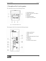
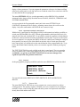
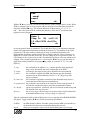
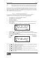
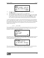
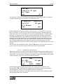
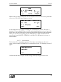
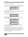
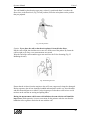
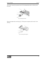
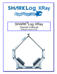
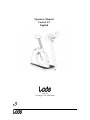
Operator Manual
Corival V2
English
Lode BV
Groningen, The Netherlands
0336
Operator Manual
Corival
PRECAUTIONS
Caution: This device should only be sold by, or on the order of authorized persons.
Caution: Not suitable for use in the presence of flammable anaesthetics.
Service of this device is restricted to factory-trained personnel only.
Note: The voltage selector (115/230VAC) is inside the ergometer. The back panel has to be
unscrewed. Voltage selection should be done by a technician!
LIST OF SYMBOLS USED
On/Off switch
External Input
External Output
Type B Electrical Safety
This is the operator manual for the Lode Corival Ergometer. If you need more detailed
information, we refer to your local distributor or the user guide (only available in
English).
Operator Manual
Corival
Table of Contents
1
DESCRIPTION OF THE CORIVAL ERGOMETER
1.1
1.2
1.3
MANUAL CONTROL QUICK START
ANALOG EXTERNAL CONTROL
TERMINAL º DIGITAL EXTERNAL CONTROL VIA RS232
5
6
7
7
2
MAIN MENU
8
3
SYSTEM PARAMETER
9
3.1
3.1.1
3.1.2
3.1.3
3.1.4
3.1.5
3.1.6
3.2
3.3
3.3.1
3.3.2
3.3.3
3.3.4
3.4
3.4.1
3.4.2
3.4.3
3.4.4
3.4.5
3.4.6
3.4.7
3.4.8
3.4.9
4
SPECIFICATIONS
4.1
4.2
5
TECHNICAL SPECIFICATIONS
FUSES
COMMUNICATION PORTS
5.1
5.2
5.3
5.4
A
SET DISPLAY
Power
RPM
Heartrate
Torque
Timer
Distance
SET P-SLOPE
SET MODE
Hyperbolic
HR controlled
Linear
Fixed Torque
SETTINGS
Default Startmenu
Keyboard On/Off
Test Functions
P In/Out Analog
ECG Trigger
TC Bytes
RS232 Protocol
Language
Device No
RS232
LOOP CONNECTION
RS-232 SPECIFICATIONS
ANALOG IN/OUT
Maintenance
A.1
A.2
A.3
B
Cleaning
Replacing fuses
Adapting the Voltage
Programmable Control Unit Top 928810
B.1
Installing the Programmable Control Unit Top (option 928810)
B.2
Control panel Corival with Programmable Control Unit (option 928810)
B.3
Using the Programmable Control Unit
B.3.1
Menu structure programmable control unit
B.3.2
Manual menu
B.3.3
Analog menu
B.3.4
Terminal menu
B.3.5
System parameters menu
B.3.6
Operation from basic control panel
B.3.7
Protocol
C
Heart rate option 928824
C.1
C.2
Connecting the Heart rate system (option 928824)
Using the Heart rate option
9
9
9
9
9
9
9
9
9
10
10
10
10
10
10
10
10
10
11
11
11
11
11
12
12
12
13
13
13
13
13
14
14
14
14
15
15
15
15
16
17
17
17
18
19
19
25
25
25
Operator Manual
D
Corival
Blood pressure option 928815
D.1
D.2
D.2.1
D.2.2
D.3
D.3.1
D.4
D.5
D.6
Using the BP system
Patient Hook-up
Apply the cuff
Position of the cuff
Installing the BP cuff
Analog ECG trigger
Abort codes BP system
Cleaning and disinfection
Cleaning of the cuff:
26
26
27
27
27
29
29
29
30
30
Operator Manual
Corival
1 Description of the Corival ergometer
The control panel consists of the following elements:
1.
2.
3.
4.
5.
6.
Led indicator for rpm
Display A directed to test subject
Down button
Up button
Confirmation button
Ergometer type indication
Fig. 1 Control Panel standard Corival
The back panel of the Corival contains the following elements:
1.
2.
3.
4.
5.
6.
7.
8.
9.
Mains on/off switch
Mains connector
Fuse
Fuse
Dealer information label (if used)
RS232 in
RS232 out
Analog i/o
Protective Earth connector
Fig. 2 Back panel connections
5
Operator Manual
Corival
Adjustability
The ergometer is adjustable to test subjects of all sizes and ages.
• The height of the saddle can be adjusted by tilting the handle on the back underneath the
saddle
• The height of the handlebars can be adjusted by loosening the screw knob in front of the
ergometer.
Moving the ergometer
The ergometer can be moved by turning it over to the right (appr. 30▼) when you are in front
of the handlebar. A wheel in the middle of the ergometer drops out. You can now drive the
ergometer to its location. Turn it over to the left (appr. 30▼) and the wheel in the middle will
fold in. The ergometer is ready for use.
Instructions for installing the Corival ergometer
1.
Place the ergometer in the location where it will be used.
2.
Check (at your supplier) whether the voltage set for the ergometer is set correct.
3.
Connect the power cord first to the socket of the ergometer and then connect it to the
line voltage.
4.
Switch the power switch on. The indicator lamp in the switch lights up.
If the following initialisation screen with the software version will appear for a few seconds,
the ergometer is ready for use.
1.1
Manual control quick start
If the Corival is switched on, the default startup menu is the entrance to the MAIN MENU.
Press the confirmation button ( ) to enter the main menu. Select with the arrow keys ▲ ♥ the
MANUAL MODE. Press ( ) and you will see the following screen:
P=
0W
0 rpm
MANUAL
With the ▲ ♥ keys the workload can be in- or decreased. The workload will rise with 25
watt/sec when the rpm is above 30. Keeping the ( ) pressed for a few seconds allows you to go
up one or more menu levels.
During cycling, the display shows the following information:
• the top line shows 1 or more ergometry parameters.
• the bottom right corner shows the current control mode.
• at the bottom left position the selected adjustable parameter is shown.
6
Operator Manual
1.2
Corival
Analog external control
Execute the following steps to control the Corival externally using the analog in-/output:
1.
Connect the external controling device (e.g. ECG system) with a correct cable to the
analog i/o port.
2.
Start the ergometer and go in the main menu to ANALOG.
3.
Now the ergometer can be controlled by an external device with an analog signal.
1.3
Terminal
digital external control via RS232
For digital external control using the RS232 serial port execute the following steps for the
basic Corival:
1.
Connect the Corival to the external control device (i.e. ECG system, PC) using a
correct RS232 cable
2.
Switch on the ergometer and select the menu TERMINAL on the display.
3.
Be sure that the correct protocol has been selected under the menu SYSTEM
PARAMETERS / SETTINGS / RS232 PROTOCOL
For a list of available protocols and ECG system, we refer to the user guide or your local
dealer. If you usually control your ergometer from an ECG system in the TERMINAL
MODE, you can set this mode as default startup menu. The Corival is now ready for digital
external control. Another option to control the ergometer from a pc is with the Lode
Ergometry Manager (LEM, article 92890X) software. This uses the Lode 38k4 protocol.
7
Operator Manual
Corival
2 Main menu
When the ergometer is started after pressing the confirmation button ( ) you enter the MAIN
MENU. The following submenus are selectable from the main menu:
TERMINAL
MANUAL
ANALOG
SYSTEM PARAMETER
Use the arrow keys▲ ♥ to scroll through the menus. Press the ( ) button to select a menu.
Keeping the ( ) pressed for a few seconds allows you to go up one or more menu levels,
wherever you are in the menu. The complete menu structure is shown below. In front of each
menu the level depth is indicated.
0. MAIN MENU
1. ANALOG
1. MANUAL
1. TERMINAL
1. SYSTEM PARAMETER
2. SET DISPLAY
3. POWER
3. RPM
3. HEARTRATE
3. TORQUE
3. TIMER
3. DISTANCE
2. SET P-SLOPE
2. SET MODE
3. HYPERBOLIC
3. HR CONTROLLED
3. LINEAR
3. FIXED TORQUE
2. SETTINGS
3. DEFAULT STARTMENU
3. KEYBOARD ON/OFF
3. TEST FUNCTIONS
3. P IN/OUT ANALOG
3. ECG TRIGGER
3. TC_BYTES
3. RS232 PROTOCOL
3. LANGUAGE
3. DEVICE NO
8
Operator Manual
Corival
3 System parameter
In the System Parameters different specific ergometer settings can be carried out.
3.1
Set display
This function allows you to adjust the parameters which can be read out on the display during
exercising. If more then 2 are set to ON they are shown in groups of 2 scrolling. Choosing
default allows you to go to factory settings for the display parameters.
Press the ( ) button to go to the next parameter and switching the actual parameter ON/OFF is
done with ▲ ♥ keys.
3.1.1
Power
Power indication in watts can be switched ON or OFF using the ▲ ♥ keys. The power
displayed is the actual power of the brake. When rpm drops below 25 rpm the load is removed
at once, because the pedal torque becomes very high. Load is put on the brake when rpm is
greater or equal to 30 rpm.
3.1.2
RPM
Swith ON of OFF the Cadence readout in Revolutions per minute. The rpm can always be
read out by the LED bargraph on top of the display independent of this adjustment.
3.1.3
Heartrate
Switch ON or OFF the Heartrate indication in beats per minute. The α symbol is used in the
display.
3.1.4
Torque
Switch ON or OFF the Torque in the readout. The Torque is displayed in Newtonmeter.
3.1.5
Timer
Switches the Timer ON or OFF in the readout. The timer is shown in the display as: → =
mm:ss. The timer starts when you enter manual, terminal or analog mode and the rpm
increases above 30. The timer is reset when one of these modes is left.
3.1.6
Distance
Switches the distance ON or OFF. The distance is shown in the display as: ▼ = 99,9 km ,
expressing the distance in km. A fictive formula is used (see user guide), holding only for
average cycle conditions and it should not be used for diagnostic purposes.
3.2
Set P-slope
The load regulation steepness is set by this parameter to the default norm-value of 25 watt/sec
or to unlimited.
3.3
Set mode
Set mode is used to define which parameter (like workload, torque, heart rate and linear
constant alpha) has to be adjusted during exercising in MANUAL mode with▲ ♥ keys
9
Operator Manual
3.3.1
Corival
Hyperbolic
Hyperbolic mode means that the workload P can be adjusted in watt. The workload is kept
constant independent of rpm.
3.3.2
HR controlled
Heart rate can be adjusted and the workload is regulated until the adjusted heart rate is
reached. This means when heart rate increases above the adjusted level load is decreased and
the other way around.
3.3.3
Linear
In linear mode the workload P is coupled with rpm using the following formula:
P [W] = π* (n [min-1] )2
The linear coupling constant πis the adjustable parameter in this case.
3.3.4
Fixed Torque
In Fixed Torque mode the workload is regulated such that the torque is kept at a set fixed
value, according the formula:
T [Nm] = (P*60) / ( 2 * Ω* n [min-1])
3.4
Settings
Under settings all device specific and interface adjustments can be made. It concerns to all
those items not related directly to ergometry.
3.4.1
Default Startmenu
Normally your ergometer starts in the main menu. But you can modify this menu to your own
desired settings. This is convenient when your ergometer is used often in the same setting,
The following menus can be selected as startmenu: MAIN MENU; MANUAL; TERMINAL;
ANALOG At the next startup of your ergometer the selected menu will be activated.
3.4.2
Keyboard On/Off
If you do not want to interrupt a training or you do not want the test subject to interrupt the
training by pressing a key accidentally, the possibility is offered to disable the keyboard
Now you wonder how to get back the control to the keyboard. Act as follows:
Switch off the ergometer
Switch it on again while keeping the ( ) button pressed. Now you have back the control. Go to
SYSTEM PARAMETERS / KEYBOARD ON/OFF and set it to ON.
At the next startup of the ergometer the keyboard is enabled again.
3.4.3
Test Functions
For servicing and calibration of the device a number of diagnostic tools is available in the
software. They are hidden under Test functions. You need a safety code to enter the
TESTFUNCTIONS.
3.4.4
P In/Out Analog
The ergometer can be controlled by an external device which has an analog output only. This
is done using the ANALOG mode. With P In/out Analog the analog scaling can be adjusted: 1
V analog in can correspond with a workload of 100 W / 200 W / 500 W.
10
Operator Manual
3.4.5
Corival
ECG Trigger
When the blood pressure option 928815 is used a heart rate trigger signal is obligatory
3.4.6
TC Bytes
The Test code (TC) Bytes offer in case of malfunction or poor performance of the BP option
928815 the possibility to make error codes visible. Your local distributor can help you
diagnose the problem with the Error Code.
3.4.7
RS232 Protocol
When the ergometer is externally controlled via RS232 a protocol should be selected here.
3.4.8
Language
You can choose different languages for the ergometer.
3.4.9
Device No
When RS232 communication is used with the ergometer, it is identified with a so called
device number. This offers the possibility of looping through ergometers.
11
Operator Manual
Corival
4 Specifications
4.1
Technical Specifications
Principle
Mains voltage
Frequency
Patient capacity
Power consumption
Workload
Device control
Accuracy
:
:
:
:
:
:
:
:
Read-out load
Read-out pedaling speed
:
:
eddy current brake
115-230 VAC (adjustable)
50 Hz, 60 Hz
350 lb - 160 kg
120 VA
0-999 W HYP, 0-999 W LIN
manual, external analog, external digital
< 3W for P<=100W, < 3% for 100W< P<500W,
<5% for P>500W
digital, 0-999 resolution 1 W
analog, 0-180 rpm or digital 0-255
Output load
Output pedaling speed
Input voltage for external control
:
:
:
100, 200 or 500 W 1 volt (max. 999 W)
100 min-1 1 volt
100,200 or 500 W 1 volt (max. 999 W)
Safety class Corival and Corival P
Safety class Corival PB
:
:
I type B, IEC 601-1 chapter 18, 19 and 20
IIa type B, IEC 601-1 chapter 18, 19 and 20
Leakage current
Isolation resistance
Earthway resistance
:
:
:
< 0.4 mA
> 4 M‘
< 0.2 ‘
Zero load
Noise level
:
:
< 8 W at 60 rpm
+/- 60dB at workload 200W/60rpm +/-80cm
from crank
:
:
2 x 1,25A slow
2 x 0,63A slow
4.2
115V
230V
Fuses
12
Operator Manual
5
Corival
Communication ports
This chapter describes the communication ports in the back panel of the Corival:
RS232 (two ports for RS232-in and loop connection RS232-out)
Analog in/out
5.1
RS232
The Corival has two RS232 connectors for loop-connecting a number of Corivals and for
communication with a personal computer or an ECG device. When the ergometer is
controlled externally always use the RS232-in port.
Via RS232 an ergometer can be monitored and settings can be entered with a computer.
5.2
Loop connection
It is possible to control several Corival ergometers with one external device using RS232.
Connect the RS232-in connector to the external device. Connect the RS232-out connector to
the RS232-in connector of the following Corival ergometer, and so on. The maximum number
of Corival ergometers that can be connected in this way is 8. Use the device number option in
SYSTEM PARAMETERS to give each Corival a unique number. In this way each Corival
can be controlled separately, using the LEM software.
5.3
RS-232 specifications
See user guide for detailed information
5.4
Analog in/out
This connector can be used to connect the Corival to other analog controlling instruments. See
user guide for detailed information.
13
Operator Manual
A
Corival
Maintenance
The Corival is designed mechanically and electronically for durability and accuracy, but it is
recommended to have the load settings calibrated regularly. The frequency of calibration
depends on the intensity of usage. The calibration is performed using calibration equipment
specially designed by the manufacturer.
A.1 Cleaning
The housing of the Corival ergometer and all other external surfaces can be cleaned with a
cloth dampened with non-aggressive liquid.
A.2 Replacing fuses
You will not need a certified technician to replace fuses of the Corival.
Always disconnect the power cord first!
Unplug the mains cable. The fuses are part of the main unit. With a screwdriver unscrew the
fuse holders, replace the broken one and place them back again. Note: make sure that the
fuses that are in the Corival match the set voltage (115V : 2 x 1,25A slow; 230V : 2 x 0,63A
slow).
A.3 Adapting the Voltage
You are allowed to adjust the voltage set for the Corival to local requirements. Execute the
following steps to do this. It is recommended to let a technician perform the voltage selection.
Always disconnect the power cord first!
The voltage selector is inside the unit. Unscrew the back panel using a screwdriver. Shift the
main unit outside for approximately 10 cm. The voltage selector is located behind the fuses
near the transformer. Adjust the voltage with a screwdriver to your local mains voltage. Shift
back the main unit and screw it. Take care not to jam wires or tubes.
Contact your local dealer for a maintenance contract or ask Lode:
LODE BV
Service department
Zernikepark 16
9747 AN Groningen
The Netherlands
Tel. +31 50 5712811
Fax. +31 50 5716746
Email: [email protected]
Internet: www.lode.nl
14
Operator Manual
B
Corival
Programmable Control Unit Top 928810
B.1
Installing the Programmable Control Unit Top (option 928810)
When the option 928810 is ordered later on, it should replace the standard Control Unit.
Replacement should be carried out by service personnel only. For the description, we refer to
our user guide supplied with this ergometer.
B.2
Control panel Corival with Programmable Control Unit (option 928810)
1.
2.
3.
4.
5.
6.
B.3
Display B (4x20 characters) directed to
operator
Infrared window (only active for option
928820)
One-step-back button
Down button
Up button
Confirmation button
Using the Programmable Control Unit
Check if the ergometer is properly installed.
In the display of the basic control panel the following appears for a few seconds:
LODE ERGOMETER
TYPE
Followed after a few seconds by:
P=
0W
0 rpm
At the same time the programmable control panel shows for a few seconds:
P-display
LODE
ver X.YZ
With an installed Bloodpressure Option it is followed for approximately 1 second by
(indicating correct operation of the BP device):
15
Operator Manual
Corival
LODE ERGOMETER
BPM initialized
Then the main menu appears:
system parameter
TERMINAL
manual
Term
The menu displayed in capitals can be selected. As extra reminder the first 4 letters of the
selectable mode are showed above the confirmation button. With the ▲ ♥ keys you can scroll
through the other menus and select SYSTEM PARAMETERS, MANUAL, ANALOG or
PROTOCOL. With the right ( ) confirmation button the menu in capital can be selected. The
left ( ) escape button is used to go back one level in the menu structure.
The ergometer is now ready for use. If nothing appears in the display(s), check whether the
power cord and the control unit have been properly connected or contact your supplier.
B.3.1
Menu structure programmable control unit
0. MAIN MENU
1. ANALOG
1. MANUAL
1. TERMINAL
1. SYSTEM PARAMETER
2. SET DISPLAY
3. POWER
3. RPM
3. HEARTRATE
3. TORQUE
3. TIMER
3. DISTANCE
3. TARGET HR*
3. ENERGY*
2. SET P-SLOPE
2. SET MODE
3. HYPERBOLIC
3. HR CONTROLLED
3. LINEAR
3. FIXED TORQUE
2. SETTINGS
3. DEFAULT STARTMENU
3. P IN/OUT ANALOG
3. CONTRAST
3. ECG TRIGGER
3. TC_BYTES
3. RS232 PROTOCOL
3. LANGUAGE
16
Operator Manual
Corival
3. DEVICE NO
1. PROTOCOL*
2. PROTOCOL EDIT *
2. PROTOCOL RUN *
2. PROTOCOL DELETE *
Compared to the standard version the *menus are added.
B.3.2
Manual menu
Selecting the manual mode will show you (default) the following display at the programmable
control panel:
MANUAL
P = 0W
θ = 0/m*
esc
P
0 rpm
P
BPM*
BPM* is displayed when this option is available, otherwise another MENU possibility is
active. With the ▲ ♥ keys you can increase or decrease the parameter of the selected mode.
In the middle the adjustable parameter is shown, f.i. the load P (to be set with SYSTEM
PARAMETERS> SET MODE)
B.3.3
Analog menu
Selecting the ANALOG menu will show the following screen at the programmable panel:
ANALOG
P = 0W
θ = 0/m*
esc
0 rpm
esc
Notice: θ = 0/m* Only displayed if BPM option is being installed!
The ergometer is now ready for external control with an analog signal as previously
described. See for more information about analog control the user guide (only available in
English) supplied with the ergometer.
B.3.4
Terminal menu
Selecting the TERMINAL menu will show the following screen at the programmable panel:
TERMINAL
P = 0W
θ = 0/m*
esc
P
0 rpm
esc
Notice: θ = 0/m* Only displayed if BPM option is being installed!
17
Operator Manual
Corival
The ergometer is now ready for digital external control. For more information about digital
external control using the RS 232 serial port see the user guide supplied with the ergometer.
B.3.5
System parameters menu
In the SYSTEM PARAMETERS different ergometry specific settings can be carried out as
described previously in the standard manual. On the programmable control panel you can
select the desired menu:
set p slope
SET DISPLAY
settings
The menu displayed in capitals and repeated with an abbreviation under the confirmation
button ( ) is the one which can be activated. Selecting one of these menus will show you a
more extended display then described previously in this manual. As you can see with the
example of SET DISPLAY:
POWER
On
Esc
off
on
next
Where the function POWER is the same as described previously in this manual (power
indication on or off), the button SYS will bring you back to the system parameters menu.
With the ▲ ♥ keys you can select the power indication to be ON or OFF, and NEXT will
bring you to the next item of the SET DISPLAY menu. Beside the parameters RPM, HEART
RATE, TORQUE, TIMER and DISTANCE two more are parameters are added: TARGET
HEART RATE and ENERGY.
Selecting the target HR parameter will show you the target heart rate programmed in the heart
rate controlled protocol beside the actual heart rate. For instance:
2 t=00:48
=01:12
P= 23 W
61 rpm
θ= 91/min tθ=100/min
recovery
ok
Selecting the energy parameter will show you the total amount of mechanical energy
delivered by the test subject going into the ergometer in the form of mechanical motion,
during the exercise test.
Instead of 2 items you can show 4 items out of your selection at once, they will scroll in
groups of 2. When you select 4 parameters, there will be no scrolling but a fixation on the
18
Operator Manual
Corival
display of these parameters. You can program the parameters (also up to 4 without scrolling)
at the basic control panel as well, but you have to switch the control over to the basic side first
as is described in the next paragraph.
The menu SETTINGS will give you the opportunity to select PROTOCOL as a default
startmenu besides the previously described menus ANALOG, MANUAL, TERMINAL and
SYSTEM PARAMETERS.
An extra option for the Programmable control unit in the menu SETTINGS is the
CONTRAST adjustment for the P-display. Adjusting contrast shows direct effect on the
display. Only after confirmation with SAVE the new contrast is kept!
B.3.6
Operation from basic control panel
With the basic control panel as described previously in this manual you had the possibility to
switch your KEYBOARD ON or OFF. With the programmable control panel the basic (test
subject) side of the unit is default OFF. It is possible to control the ergometer with the buttons
of the basic control panel instead of the programmable control panel. You can use this option
for service purposes or to program the display of the basic control panel. During the startup of
the ergometer you can press one of the buttons at the basic side to switch operation to this
basic control panel, you will then loose the control function of the programmable side. To go
back to the default control situation you have to restart the ergometer without pressing any
button.
The TEST FUNCTIONS are only available at the basic control panel. They are meant for
service personnel only. Contact your supplier in case service of the device is required. If,
accidentally, you get into to the TEST FUNCTIONS it can cause damage to the
ergometer operation and guarantee will be lost!
B.3.7
Protocol
In this paragraph the program possibilities under the menu PROTOCOL will be described:
protocol run
PROTOCOL EDIT
protocol delete
Prot
Prot
You can select the menus PROTOCOL EDIT; PROTOCOL RUN and PROTOCOL
DELETE.
B.3.7.1
Protocol edit
The menu PROTOCOL EDIT allows you to program new exercise protocols or edit an
existing protocol. The memory capacity will allow you to save 50 protocols, all existing of
maximal 15 steps each. Pressing this menu will show you the list of protocols which have
already been made and the menu NEW.
19
Operator Manual
Corival
New
name1
name2
esc
ok
With the ▲ ♥ keys you can select the desired protocol (in this example name1) to edit. Select
NEW to program a new exercise protocol and give the protocol a useful name maximal 10
characters with the▲ ♥ keys. The allowed characters for the name are: ’0∆..∆9∆,∆a∆..∆z∆,
and ∆ ∆. Move the cursor with the confirmation button ( ) OK to the 10th position and the
program screen will appear:
Name 1
Step P= 0W t=00:00
1S dP=+050W dt=060s
Esc
ok
On top the protocol name is mentioned. The second line will give you information about the
status of the programmed momentary workload (P) and time (t). The third line is the actual
program line. The stage number with the type of stage is mentioned, followed by the
programmable parameters (workload in the above example) and time. Those parameters are
displayed as ♪ Power (dP) and ♪ time (dt). ♪ P is the change in power expressed in watts. ♪ t
is the change in time expressed in seconds. The underlined character is the item which can be
changed, in the example mentioned above: S. Pressing the ▲ ♥ keys give you the ability to
toggle between the possibilities for programming a stage in a protocol: S, T, L, H, P and
Recovery.
the workload can be adjusted + or º and the duration of this hyperbolic
stage can be determined; the load is independent of the RPM
T= torque
fixed torque: the torque in Nm can be adjusted with certain duration
L= linear
the workload is coupled with RPM with constant πas the adjustable
parameter for the desired duration; load P = π* N2 [W] goes up with
square of cadence.
H= heart rate
the workload is regulated as a function of the adjustable heart rate for a
certain duration in this heart rate controlled step.
P= proportional the workload is increased linear as a function of time (ramp protocol). It
will take the total duration time to reach the programmed workload;
R = Repeat
repeat steps (until max. workload): you have to enter the workload step and
the duration of the step only once.
Recovery
the recovery stage is the last stage of a protocol with a fixed workload and
an unlimited duration (only 1 recovery stage in 1 protocol)
S= step
After the confirmation of the workload during the recovery stage the menu PROGRAM BPM
will appear. Toggle with the ▲ ♥ keys for the measurement possibilities:
No BPM
Repeat
no BPM module available, select this option when the BPM is not installed, or
no automatic blood pressure measurement during this protocol;
allows you to program a repeat time in minutes during the exercise stages:
20
Operator Manual
EOS
Corival
End Of Stage; automatic measurement at every end of the exercise step with
the possibility to program the measurement time before the end of the stage.
Recovery time If you have programmed automatic BP measurement in the protocol, you get
the possibility to program the repeat time of the BP measurement during the recovery stage:
After the programming of the BPM the menu PROTOCOL will appear again. You can RUN
EDIT or DELETE one of the protocols now.
B.3.7.2
Example Programming Protocol
For the purpose of clarification we will program a demonstration protocol with all
possibilities. Execute the following steps to get into the programming mode.
1.
2.
3.
4.
5.
6.
Select PROTOCOL in the MAIN MENU, confirm ( )
Select PROTOCOL edit, confirm ( )
Select New, confirm ( )
Give a protocol name: test
With the ▲ ♥ keys you can scroll through the alphabet confirm, use OK ( ) to go to
the next position
The program screen appears, the underscore showing the programming parameter:
test
Step P= 0W t=00:00
1S dP=+050W dt=060s
esc
next
7.
8.
9.
Confirm the S with ( ), use the ▲ key to decrease the workload to 10 watt.
Press the confirmation button OK until you reach the following screen. Adjust time dt
to 60 seconds using the ▲ ♥ keys.
Select T with the ▲ ♥ keys and adjust the Torque to 10 Nm and the duration to 30
seconds with
the same keys.
Press the
confirmation
test
button.
Torq P= 10W t=01:00
2T T= 10Nm dt=030s
esc
next
10.
11.
12.
13.
Select L with the ▲ ♥ keys and confirm the constant π=0.041, change the duration to
10 seconds. Press the confirmation button.
Select H with the ▲ ♥ keys and change the heart rate in 120/m for a duration of 180
seconds, press the confirmation button.
Select P with the ▲ ♥ keys and change the Workload to 150 in duration of 300
seconds, press the confirmation button.
Select P with the ▲ ♥ keys and change the Workload to minus 60 in 60 seconds, press
the confirmation button.
21
Operator Manual
Corival
test
Ramp P=160W t=09:40
6P dP=-060W dt=060s
esc
next
14.
15.
16.
Select Recovery the ▲ ♥ keys and change the Workload to 35 and press the
confirmation button.
After confirmation you will automatically go to the BPM menu.
Select No BPM when the BPM module is not installed or select Repeat with the ▲ ♥
keys and choose 2 minutes for the repeat time, confirm with ( ) and choose 2 minutes
for the repeat time in the recovery stage. The protocol TEST (with BPM) is ready
now, you can go to protocol RUN to test this special protocol (not for normal use).
To edit an existing protocol, you have to select the desired protocol first. You can change the
name or confirm the name with OK ( ) ten times. Now you can walk through the stages with
the confirmation button, until you reach the stage you want to edit. You have to scroll through
the total protocol and define the recovery stage before you leave this menu otherwise the
changes will not be saved.
B.3.7.3
Protocol Run
The menu PROTOCOL RUN is used to select the desired protocol for the exercise test. Select
Protocol Run and three previously programmed protocols will appear on screen. To scroll
through the total list use the arrows, for instance:
10w min
25w 2 min
ramp 400w
esc
ok
If you want to select e.g. the protocol 10 w min, use the ▲ key until a space appears in front of
the name of the protocol (the selectable item is always on the 2nd line) and confirm with ok.
The following message will appear on screen:
10w min
1 P=0W t=00:00
1S dP=+10W dt=060s
esc
ok
This screen is used to check the selected protocol; in this case the name is 10w min: the first
step will start with 10 watt for 1 minute. Press the confirmation button to go on:
22
Operator Manual
Corival
10w min
start at 30 rpm
n= 0/min
esc
ok
The ergometer is ready for use with the selected protocol. When the test subject exceeds the
30 rpm the protocol will run. You will see the following screen:
1 t=00:59
P= 10 W
θ = 83/min
rec
=00:01
58 rpm
rec
In this example the screen shows that this is the first stage, t= 00:59 with 59 sec to go, the
timer is showing 1 sec of total exercise time, the timer will stop the registration when the
RPM drops below 30. The workload P is 10 watt, the pedaling frequency is 58 RPM, and the
heart rate is 83 beats per minute. The three displayed parameters are those selected under
SYSTEM PARAMETERS / SET DISPLAY. At the bottom line you will find the recovery
button on the left which will bring the workload immediately to the programmed recovery
workload, and the OK button. In case the optional BPM is installed you will find instead of
this OK button a BPM button which allow you to measure the blood pressure with the
optional automatic blood pressure module (see the appendix concerning Blood pressure in this
manual).
The next steps will automatically follow. With the ▲ ♥ buttons you can go the next stage or
previous stage when you do not want to follow the protocol as programmed.
B.3.7.4
Blood Pressure Measurement
When your controller is extended with the optional automatic blood pressure module you can
either program a measurement interval (see Protocol edit B.3.7.1 and Example Programming
Protocol B.3.7.2) or press the ( ) BP button (see appendix on BP measurement) to start manual
a BP measurement. You will see the selected display parameters.
BPM
P= 30W
θ = 114/min
esc
DISP
60 rpm
START
Pressing PROT (protocol) will bring you back to the normal exercise protocol screen.
Pressing DISP (▲ ♥ ) will allow you to toggle between the BP parameters and de default
selected parameters. START will start the blood pressure measurement.
Pressing DISP again will show as next display the actual pressure p and each heart rate beat
and Korotkoff sound on the second line:
23
Operator Manual
Corival
BPM
p = 123 mmHg
P= 30W
esc
DISP
αԀ
60 rpm
START
Whenever the test subject is allowed to or has to stop the exercise test, the recovery button has
to be pressed. The following will appear on screen:
Rec P= 50W
P= 50W
θ = 174/min
esc
t=10:30
60 rpm
esc
In this example the recovery phase will bring the workload down to 50 watt. The timer is
showing 10:30 seconds and will go on with the registration during the recovery as long as the
RPM is above 30 (the BPM can still be measured when BPM is displayed at the confirmation
button). To stop the recovery phase press the END button to go back to the PROTOCOL
menu. In the menus MANUAL, TERMINAL or ANALOG the BP function is the same as
described above.
B.3.7.5
Protocol delete
This function allows you to delete a protocol. Select the protocol which you do want to
remove (in this example TESTPROTOCOL) and confirm with OK. The following screen will
appear:
testprotocol
Delete?
esc
ok
Confirm with OK when you agree and the message [deleted] will appear on the screen
24
Operator Manual
C
Corival
Heart rate option 928824
C.1
Connecting the Heart rate system (option 928824)
To install a heart rate option purchased afterwards, follow the instructions given in the user
guide supplied with the ergometer. Installation of the Heart rate option itself has to be done by
service personnel only.
C.2
Using the Heart rate option
The heart rate option is automatically recognized by the ergometer. The Polar belt should be
mounted around the chest of the test subjects (at heart level) with Polar trade mark pointing
forwards from the middle of the chest. The belt should not be to loose. If you have a weak
signal, check following tips:
• Wet the contacts on the right and left backside of the Polar belt for good contact
• Stay near the receiver (within a range of 1 meter) which is located in the display unit
at the test subjects side below the readout.
• Due to the integration measurement principle it can take a few seconds before the
readout on the display shows the correct value. Be patient.
• The test subject should be positioned in such way that a straight virtual line can be
drawn between the Polar trade mark on the belt and the receiver inside the display
unit.
25
Operator Manual
D
Corival
Blood pressure option 928815
With option 928815 it is possible to perform stand alone or external controlled blood pressure
measurements. After installation (Appendix D.3) the BP module is recognized automatically
at start up of the ergometer, indicated by the following screen for a few seconds:
LODE CORIVAL
BPM Initialized
D.1
Using the BP system
Caution: Carefully read the instructions in Appendix D.2 Patient Hook-up and D.2.3 Notes on
blood pressure measurement before continuing. Only well trained medical personnel, familiar
with BP measurement, should operate the BP system.
When you are in the MANUAL, TERMINAL or ANALOG mode you can go to the BP
measurement by pressing ( ) button. The following menu appears:
P= 90W
69 rpm
DISP START MAN
In the upper line of the display still your selected readout parameters appear. The buttons
below have the following functions:
▲
DISP: Toggle the display between your readout parameters and the pressure p [mm
Hg]. Pressure is indicated as lower case p and workload with upper case P.
P =
DISP
0 mm Hg
START MAN
START: The BP measurement starts:
P = 120 mm Hg
DISP STOP
MAN
With the same button the BP can be aborted at any time and the pressure will be released.
()
MAN / TERM / ANA: Return to the operation mode where you started from
(MANUAL, TERMINAL or ANALOG).
During the first BP measurement of the test subject the cuff inflates to 180 mm Hg. For each
subsequent BP measurement, the last measured SYSTOLIC value +50 mm Hg is used as a
maximum inflation limit. Be aware that in case of an error (D.4) the inflate limit can go up to
260 mmHg worst case. Above 300 mm Hg, or if a measurement lasts longer than 180
seconds, the hardware releases pressure immediately for safety reasons. Deflation is done 40
mm Hg below the last measured DIASTOLIC pressure. The used deflate rate is
approximately 4 mm Hg/heartbeat.
26
Operator Manual
Corival
Under DISP ▲ an extra menu is available especially useful during deflation. Besides the
pressure, also the real time heart rate and Korotkoff tone are indicated. Each heart rate is
shown with the symbol α and Korotkoff as Ԁ.
When BP has finished the SYSTOLIC and DIASTOLIC values are shown in the upper line.
S/D 120/ 80 mmHg
DISP START MAN
With the DISP ▲ the average heart rate during the BP can be made visible:
BPM HR θ 64/m
DISP START MAN
When DISP ▲ is pressed once more, you are back in the normal screen. So the BP readings
are available only once after the measurement.
A list of most occurring warnings and errors is given in D.4 Abort codes BP system.
The built-in BP module offers, in case of malfunction or poor performance, the possibility to
make error codes visible. See for more information the user guide supplied with this
ergometer.
Caution: The interpretation of the error codes should be done only by experts. Ask your
supplier for more information.
D.2
Patient Hook-up
Correct patient hook-up is very important. Experience has shown that a lot of troubles can be
avoided when the rules below are kept in mind. Especially BP measurement using Korotkoff
tones under stress requires accurate preparation.
D.2.1 Apply the cuff
On the inside of the upper arm you can feel the brachial artery. Palpate the brachial artery to
ensure proper placement. The best place for the microphone is where you can most clearly
feel the pulse (Fig. 23 Palpating the arm). Upper clothing should be taken off!
Pulled up garments should not jam the upper arm.
Fig. 23 Palpating the arm
D.2.2
Position of the cuff
27
Operator Manual
Corival
The cuff should be placed on the upper arm, so that it is positioned about 2 cm above the
elbow close to the heart level (Fig. 24 Cuff position). Place the microphone on the position
that you palpated.
Fig. 24 Cuff position
Caution: Never place the cuff so that the microphone is located in the elbow.
Pull the cuff so tight, that it neither moves nor ties off the arm of the patient. By fasten the
cuff too tight or too loose, error measurements are caused.
Wrap the end of the cuff around the upper arm and close the Velcro fastening (Fig. 25
Mounting the cuff).
Fig. 25 Mounting the cuff
Ensure that the air hose from the monitor to the cuff is not compressed, crimped or damaged.
During ergometry the air hose should be handled and attached in such a way, that vibrations
and movement artefacts are avoided. Use the ringstrap to fix the tubes to the wrist to avoid
tensions on the cuff due to moving and pulling tubes.
During the measurement, which starts with inflation, the arm with the cuff should be
kept in rest. With ergometry it is most convenient for the patient to take the arm from the
handlebar of the ergometer and relax the arm with the cuff.
28
Operator Manual
Corival
The intervals of the measurements should not be too short. Intervals of 2 minutes and more
result in long pauses between the stenoses, so that venous congestion and artiospasm can be
avoided.
D.3
Installing the BP cuff
To install a BP option purchased afterwards, follow the instructions given in the user guide
supplied with the ergometer.
Installation of the BP module itself has to be done by service personnel only.
D.3.1
Analog ECG trigger
The BP module offers the possibility to use an analog heart rate input signal as a trigger for
the BP measurement. Use this option if your ECG device has only an analog output available
instead of TTL. Refer to the user guide for this modification which has to been done by
service personnel only.
D.4
Prior.
Abort codes BP system
Error message
Display
Possible error cause
1
@CHECK ECG
SIGNAL!
0 / 0 mmHg
ECG trigger not connected.
ECG trigger properties not correct.
ECG trigger polarity not correct.
QRS pulse width smaller than 10 ms.
2
@CUFF
OVERPRESSURE!
0 / 0 mmHg
Strong arm movements during the blood
pressure measurement.
Air hose is bent or blocked.
3
@AIR LEAK!
0 / 0 mmHg
Cuff is loose or not connected.
Air hose or air-bubble leak.
Air hose not connected.
4
@SERVICE
REQUIRED!
BP
value
Fatal error ...Get in touch with the company
Lode.
5
@CHECK ECG/
MICROPHONE!
BP
value
Poor patient hook-up (irregular ECG-signal) or
poor trigger signal.
AND
Abnormal microphone-signal or damaged
microphone.
6
@CHECK
MICROPHONE!
BP
value
7
@CHECK ECG/
ARTIFACT!
BP
value
Wrong Microphone placement or defect
microphone.
ECG trigger signal failed during blood pressure
measurement.
Bad or irregular ECG-signal during the blood
pressure measurement.
AND
Excessive movements of the patient during the
blood pressure measurement.
8
@ARTIFACT/ARM
BP
value
Excessive movements of the patient during the
blood pressure measurement.
29
Operator Manual
Corival
MOVEMENT!
9
@CUFF INFLATION
TOO LOW!
BP
value
10
None
BP
value
D.5
Maximum cuff pressure adjusted too low.
Inflation pressure adjusted too low. Repeat
measurement.
Cleaning and disinfection
Entry- and connection cables, like the air-hose from the cuff should not be sterilized in hot
steam or cold gas or plunged in disinfectants.
D.6
Cleaning of the cuff:
For the cleaning of the cuff, you can take out the air-hose (Fig. 31 Air-hose removal).
Fig. 31 Air-hose removal
Now you can open the Velcro fastening of the cuff and take out the microphone.
Fig. 32 Microphone removal
The cuff can be washed at 30° C. The air-hose can be cleaned with mild non-alcoholic
disinfectant. There may not remain any liquid in the air-hose afterwards.
30
Operator Manual
Corival
The air-hose can easily be put back in the cuff, if beforehand both ends are rolled up to the
hose entry.
Fig. 34 Placing the air-hose
Slip the microphone back in the bag (Fig. 35 Placing the microphone) and close the Velcro
fastening.
Fig. 35 Placing the microphone
31