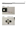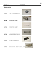
1
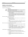
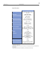
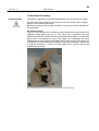
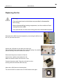
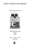
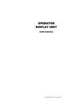
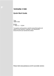
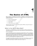
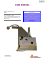
USER MANUAL
Applies to the applicator type:
LA-BO
USER MANUAL
Rev. 2.1, Release 10 /2007
© 2007, Avery Dennison Deutschland GmbH,
Postfach 1163, 85385 Eching, Germany.All
rights reserved.
General notes & Safety
instructions
Specifications
Mounting & setting the LA-BO
Servicing the LA-BO
Spare parts
Fig.: LA-BO applicator
(Shipped version may
deviate from the picture)
2
10/07 Rev. 2.1
USER MANUAL
LA-BO
3
10/07 Rev. 2.1
USER MANUAL
LA-BO
General notes & Safety instructions.…………..5
General notes .....................................................................6
Validity and binding effect of this manual ........................6
Illustrations and descriptions ...........................................7
Safety instructions ..............................................................8
Information and qualifications .........................................8
Operational safety of the unit ..........................................9
Specifications………………….………………..………11
Application Notes ..............................................................12
Intended Purpose .........................................................12
System Requirements ...................................................12
Properties ......................................................................13
Mode of Operation ........................................................13
Specifications ................................................................14
Index .................................................................................15
Mounting & setting the LA-BO….……….……….17
Safety instructions ............................................................18
Mounting on an ALX 92x ..................................................19
Required components ..................................................19
Required tools ..............................................................19
Fitting the applicator .....................................................20
Adjusting the dispensing edge to the vacuum grid .......21
Adjusting the parameter settings on the ALX 92x ........22
Mounting on an ALS 20x/256 ...........................................23
Required components ..................................................23
Required tools ..............................................................23
Fitting the applicator .....................................................24
Adjusting the dispensing edge to the vacuum grid .......25
Adjusting the parameter settings on the ALX 20x ........26
Adjusting the labeling application height ...........................27
Adjusting the LA-BO to the used label material ................28
Adjusting the sliding bars in the vacuum grid ...............28
Adjusting the air nozzles in the vacuum grid ................30
Adjusting the air stream support ...................................31
Setting the dispensing position parameter ....................32
Initializing the applicator ...............................................32
Compressed air settings ...............................................33
Index…………………………………………………………...34
4
10/07 Rev. 2.1
USER MANUAL
LA-BO
Servicing the LA-BO……………….………………….35
Pre-installation on the ALX 92x......................................36
Replacing the fan ...........................................................38
Replacing slide bars ......................................................39
Regular maintenance.....................................................40
Recommended Sparepart .............................................41
Spareparts…………………………………………………..42
5
10/07 Rev. 2.1
USER MANUAL
LA-BO
General notes & Safety instructions
General notes ................................................ 6
Validity and binding effect of this manual ... 6
Illustrations and descriptions ...................... 7
Safety instructions ......................................... 8
Information and qualifications .................... 8
Operational safety of the unit ..................... 9
6
10/07 Rev. 2.1
USER MANUAL
LA-BO
General notes
Validity and binding effect of this manual
Contents
The present manual refers exclusively to the LA-BO applicator. It is written for
the purpose of ensuring professional usage and calibration of the unit.
Prerequisites for the use and adjustment are the professional installation and
configuration of the unit. For any technical questions you may have that are
not described in the user manual, see:
•
The service chapter of this manual.
or
• Request a service technician from one of our sales partners.
Our service technicians are available to assist you, particularly with
configuring the unit as well as in the case of malfunctions.
Technical status: 10/2007
Copyright
Avery Dennison holds all rights to this manual and its appendixes.
Reproduction, reprinting or any other types of duplication, even of portions of
this manual, may only be carried out with express written consent. Third
persons, in particular competitors, should not be given access to the
information in this manual.
Printed in Holland
Manufacturer
Avery Dennison Deutschland GmbH
Ohmstrasse 3
85386 Eching, Germany
Phone: +49-8165-925-0
Fax: +49-8165-3143
http://www.machines.averydennison.com
Avery Dennison reserves the right:
•
To make modifications to construction parts, components and
software, as well as to employ comparable components in place of
the parts specified, in keeping with technical advances.
• To modify information in this document.
No commitment will be made to expand these modifications to include any
units delivered earlier.
7
10/07 Rev. 2.1
USER MANUAL
LA-BO
Illustrations and descriptions
Dangers and risk notes
Important directions that you must absolutely observe are particularly
emphasized:
WARNING!
A warning refers to risks that can lead to serious injury or death! The
warning contains safety measures to protect the relevant persons.
Always follow the instructions.
Figures
Texts are accompanied by figures where necessary.
Generally, the LA-BO unit shown is a right-handed version. The left-handed
version is only shown where it is necessary to differentiate between the two.
8
10/07 Rev. 2.1
USER MANUAL
LA-BO
Safety instructions
Information and qualifications
Follow the instructions
WARNING!
Safe and efficient operation of the LA-BO unit can only be guaranteed if
you observe all necessary information.
Product liability and warranty claims can only be asserted if the unit
was operated in accordance with the directions in the manual.
•
Before operating the unit, read the operating instructions and all
other notes carefully.
•
Observe the additional safety and warning notes on the LA-BO unit.
•
Only permit competent people to operate and configure this unit.
•
When working with the LA-BO for a longer period, it is advisable to
use hearing protection.
Keep the product information at hand
With respect to this manual:
•
It should be kept at the location where the unit is installed and be
available to the operator.
•
It should always be legible.
•
If the unit is sold, the manual should be made available to the new
owner.
•
The safety and warning notes affixed to the unit itself must be kept clean
and legible. Missing or damaged signs must be replaced.
Ensure the required qualifications are met
•
Ensure that only trained and authorized personnel operate, configure
and service the unit.
•
Only allow qualified and well-trained expert personnel or service
technicians to perform configurations.
•
The responsibilities with regard to operation, configuration and
maintenance should be clearly defined and consistently maintained.
•
In addition, personnel should also be instructed on a regular basis in
matters of occupational safety and environmental protection.
Qualification for operation
The instruction of personnel using the unit must ensure that:
•
The operating personnel can use the unit on their own and safely.
•
The operating personnel can remedy small operational disruptions on
their own.
•
At least two people must be instructed in the unit’s usage.
•
Enough label material must be provided for testing and instructional
purposes.
9
10/07 Rev. 2.1
USER MANUAL
LA-BO
Operational safety of the unit
Proper usage
Applicators of type LA-BO are additional units for Avery Dennison print-andapply or labelling heads. The applicators take self-adhesive labels from the
dispenser mechanism and stick these onto moving or non-moving products.
The company operating the unit must install it with suitable equipment to
protect operating personnel from danger; for example, the danger of hands or
fingers being crushed by reaching in between the product and the dispensing
edge.
WARNING!
Improper usage of the unit can cause accidents, property damage and
production downtime!
•
Only use the unit in accordance with the instructions specified in
this manual.
•
Only configure the unit in accordance with this manual and with the
required care.
•
Only use original accessories.
•
Do not make any modifications or alterations to the unit.
•
Repairs to the device may only be performed by authorised
specialists who are aware of the risks involved.
Protection against injuries by electrical current
Applicators of type LA-BO operate using low voltage 24 V DC supplied by
Avery Dennison print-and-apply or labelling heads.
WARNING!
•
Never connect the LA-BO unit directly to mains voltage!
•
Only operate the unit once the housing has been reassembled
properly.
•
Before cleaning, switch off the Avery Dennison print-and-apply or
labelling head and remove the power cable from the socket.
WARNING!
The unit is not protected against splashing water.
•
Keep the unit dry.
•
If liquids have penetrated the LA-BO unit, switch the Avery
Dennison print-and-apply or labelling head off and disconnect or
unplug it’s power cable immediately. Inform a service technician.
Protection against injuries by mechanical action
WARNING!
Risk of injury due to moving and rapidly rotating parts!
•
Long hair, loose jewellery, long sleeves and so on are not
permissible when using the unit.
•
Sufficient protective clothing must be worn.
10
10/07 Rev. 2.1
USER MANUAL
LA-BO
•
Keep moving parts free from obstructions even when the unit is not
switched on, if there is a chance the machine might be turned on.
•
Switch off the machine before making any mechanical settings.
•
Do not wear ties, loose clothing, jewellery, wrist watches or similar
items on your person when near the operating unit.
WARNING!
There is a low risk that you may get your hands crushed between the
vacuum grid of the LA-BO and the conveyed products!
•
Never reach between the product and the LA-BO edge while the
unit is in operation or ready for operation.
Protection against injuries by chemicals
CAUTION!
Operating materials such as cleaning agents or the solvents in glues
can be damaging to health.
•
Always follow the instructions, use and safety regulations specified
by the manufacturer!
11
10/07 Rev. 2.1
USER MANUAL
LA-BO
Specifications
Application Notes ........................................... 12
Intended Purpose ....................................... 12
System Requirements ................................ 12
Properties ................................................... 13
Mode of Operation ..................................... 13
Specifications ............................................. 14
Index .............................................................. 15
12
10/07 Rev. 2.1
USER MANUAL
LA-BO
Application Notes
Intended Purpose
Applicators of type LA-BO are additional units for print-and-apply or labelling
heads that are listed in the section "Device type". They take self-adhesive
labels from the dispenser mechanism and stick these onto moving or nonmoving products.
The LA-BO is mounted to the print-and-apply (ALX 92x) or labelling head
(ALS 20x/256) by means of an included base plate. The applicator is
controlled by the optional Applicator Interface (AI) board (mandatory for ALX
and optional for ALS) or by the Internal Applicator Interface (ALS only). The
electrical connection to the LA-BO is done via a plug connector. The drive is
provided by compressed air.
Remark: The optional Applicator Interface (AI) board is not included with the
LA-BO and has to be ordered separately with the print-and-apply or labelling
head.
The application process is triggered by means of a product sensor, which is
also connected to the AI-board.
Installation position
Permissible installation positions for the LA-BO are:
• Vertical, if application takes place from top to bottom (also referred to as
“top labelling”: the product is located below the applicator) or from bottom to
top (also referred to as “bottom labelling”: the product is located above the
applicator).
• Horizontal (also referred to as “side labelling”: the product is located next to
the applicator)
System Requirements
The LA-BO can be operated on the following devices:
Device type
Device
Part number LA-BO
Controller
ALX 924/925/926 LH2
A8679
AI1/2 (A5032/A5207)
ALX 924/925/926 RH2
A8680
AI1/2(A5032/A5207)
ALS 204/206/256 LH3
A8677
AI1/2(A7063)
ALS 204/206/256 RH3
A8678
AI1/2 (A7063)
Tab. 1: Print-and-Apply and labelling heads, to which the LA-BO can be applied (LH =
lefthand, RH = righthand, AI=Applicator Interface).
1) The Applicator Interface (AI) is not contained in the scope of delivery and has to be
ordered separately with the ALX or ALS unit.. A5032 : AI factory installed, A5207 AI Upgrade
kit
2) Use of the AI is mandatory for ALX. Use of the AI is optional for the ALS. The Internal
Applicator Interface of the ALS can be used also, but limits the use of PLC signals.
3)
ALX 924/925/926 has to be equiped with standard dispensing edge
4)
ALS 20x/256/256 has to be equiped with L-shape fixed dispensing edge
13
10/07 Rev. 2.1
USER MANUAL
LA-BO
By ordering the specified part number, you will receive a LA-BO applicator
with installation material and connection cables, suitable for installation on
the device type listed at the beginning of the line. The Applicator Interface
(AI) board is not part of the delivery and has to be ordered separately.
Firmware
Required version of the ALX 92X firmware: V3.30 or later.
Required version of the ALS 20X/256 firmware: V1.17 or later.
AI
The printer-dispenser must be equipped with an Application Interface (AI)
board version V1.11 or later.
Start signal
The start signal must be connected to the Product sensor input of the AI
interface. When the Internal Applicator interface on the ALS is used, the
startsignal must be connected to the M12-connector “ Start”
P
See service manual ALX 92x/ALS 20X/256/256, ‘Applicator Interface’ topic
section, chapter ‘Interface signals’, ‘Product Sensor’. For using the M12
connector on ALS see Service manual ALS 20x/256 ‘ Connecting the
sensors’.
Properties
LA-BO = Label Applicator – Blow On
The applicator is driven by compressed air. The label is held to the aluminium
grid on the bottom side of the applicator by an inwards airflow created by a
fan on the side of the applicator.
Mode of Operation
The fan in the LA-BO is continuously powered, creating a strong inwards
airflow through the aluminium vacuum grid at the bottom side. While a label is
dispensed, the small blow pipe is activated, creating a small focused air
stream to force the label against the aluminium grid. When the label is fully
dispensed, it is held onto the aluminium grid by the inwards airflow and is
then stand-by to blow off the label. When the application cycle is triggered by
the product sensor, a high volume air pressure is applied through the air
nozzles built-in above the aluminium grid. The nozzles which are not
covered by the black sliding bars will now blow off the label towards the
product at a high velocity. After that, the next label can be dispensed on the
grid.
14
10/07 Rev. 2.1
USER MANUAL
LA-BO
Specifications
LA-BO applicator
Material type
Label size
Application distance
Application capacity
Product speed
Self-adhesive labels of paper,
PE or PP
Min. 30 x 30 mm
Max. 100 x 100 mm
Min. 20 mm
Max. 100 mm
1
2
Up to 160 labels/min
From 0 up to 120 m/min 3
90° +/- 10°
Application angle
2
Application accuracy
Typically +/- 1 mm
Control
Applicator Interface
Compressed air
5-6 bar
Air consumption
Appr. 1 ltr/apply cycle
Dimensions
ALX 92x: 300 x 345 x 153 mm
ALS 20x/256: 357 x 188 x 153
mm
3,5 kg
Weight
Environmental
conditions
Enclosed rooms
Working temperature:
5 to 40°C
Storage temperature:
0 to 60°C
Relative humidity: 30 to 80%,
non-condensing
Protection class
IP 21
Power consumption
15 VA
Supply voltage
24 V DC (from ALX or ALS)
Noise level
82 dB(A) during blow cycle
Tab. 2: Technical specifications of the LA-BO.
1) depending on label size
2) depending on label size and time necessary for trailing edge of label to be released from
backing paper
3) Depending on labelsize, blow distance, productsurface and accuracy.
15
10/07 Rev. 2.1
USER MANUAL
LA-BO
Index
A
I
Applicator Interface 13
Installation position 12
Intended Purpose 12
L
LA-BO, properties 13
F
S
Firmware 13
Specifications 14
16
10/07 Rev. 2.1
USER MANUAL
LA-BO
17
10/07 Rev. 2.1
USER MANUAL
LA-BO
Mounting & setting the LA-BO
Safety instructions .........................................................18
Mounting on an ALX 92x ...............................................19
Required components ...................................................19
Required tools ...............................................................19
Fitting the applicator ......................................................20
Adjusting the dispensing edge to the vacuum grid ........21
Adjusting the parameter settings on the ALX 92x .........22
Mounting on an ALS 20x/256 ........................................23
Required components ...................................................23
Required tools ...............................................................23
Fitting the applicator ......................................................24
Adjusting the dispensing edge to the vacuum grid ........25
Adjusting the parameter settings on the ALX 20x/256 ..26
Adjusting the labeling application height ........................27
Adjusting the LA-BO to the used label material .............28
Adjusting the sliding bars in the vacuum grid ................28
Adjusting the air nozzles in the vacuum grid .................30
Adjusting the air stream support ....................................31
Setting the dispensing position parameter .....................32
Initializing the applicator ................................................32
Compressed air settings ................................................33
Index ..............................................................................34
18
10/07 Rev. 2.1
USER MANUAL
LA-BO
Safety instructions
WARNING!
The applicator uses a large air flow to blow off the label which is held at
the bottom side of the applicator.
–
Don’t look straight in to the vacuum grid of the running applicator,
to avoid that dust or label residues are blown into your eyes.
–
When setting the applicator: make sure that the applicator cannot
be triggered unintentionally.
• When mounting, dismounting or servicing the LA-BO, make sure the
labelling head ALX 92x or ALS 20x/256 and the air pressure are switched
off!
• The operating air pressure must be at least 5 bars and no more than 6 bars.
• The applicator may only be assembled and commissioned by qualified
personnel.
• The applicator housing may only be opened by authorized technicians.
• Repairs to the applicator may only be performed by authorized technicians
who are aware of the risks involved!
• Check the applicator regularly for defective parts. Replace defective parts
immediately and only by original spare parts provided by the manufacturer.
By doing so, you avoid hazards caused by spare parts of low quality.
• The applicator construction must not be modified (e.g. by installing a larger
pneumatic valve). Unauthorized modifications, changes or improper usage
exclude all liability on the part of the manufacturer for damage resulting
there of.
19
10/07 Rev. 2.1
USER MANUAL
LA-BO
Mounting on an ALX 92x
Required components
Component
Basic Module
LA-BO
Part number
A8679 (LH)
or
A8680 (RH)
Bolt Set (3x
screw ISO
7380 M5x20)
Filter
regulator
included
Picture
included
Tab. 1: These parts are required to mount the LA-BO on an ALX 92x.
Required tools
•
Allen key 3 mm
•
Small size screwdriver
ATTENTION :
For ALX 92x supplied before May 2007, 3 mounting holes have to be drilled in the ALX 92x groundplate. Please refer to User manual page 36 for detailed instructions.
20
10/07 Rev. 2.1
USER MANUAL
LA-BO
Fitting the applicator
1. Pull out the black top-left knob (1)
and turn the LA-BO housing in
the upper position (2).
2. Bolt the base plate of the
applicator onto the base plate of
the ALX 92x (3x M5x20).
3. Plug the cable of the LA-BO into
the D-sub connector of the ALX
92X on the top side of the printer
unit.
4. Connect the applicator to the
compressed air.
21
10/07 Rev. 2.1
USER MANUAL
LA-BO
Adjusting the dispensing edge to the vacuum grid
After fitting the applicator, the position of the dispensing edge in
relation to the vacuum grid of the applicator must be verified and
adjusted if necessary. When viewed from the side, the bottom surface
of the vacuum grid must be slightly below and in front of the
dispensing edge (see fig. 11).
Fig. 11: Position of dispensing edge to vacuum grid.
As a guideline, the center of the dispensing edge should be positioned
approximately 1 mm above the vacuum grid surface.
To adjust: Loosen the fixing screws of the angular adjustment of the
dispensing edge, rotate the dispensing edge in the desired position
and retighten the screws.
22
10/07 Rev. 2.1
USER MANUAL
LA-BO
Adjusting the parameter settings on the ALX 92x
Necessary settings for the ALX 92x
Menu
Parameter
Value
PRINT
PARAMETERS
Dispense position
0 mm (label must be entirely
dispensed)
SYSTEM
PARAMETERS
Head disp. dist.
24,5 mm
Application mode
Save Mode (recommended
for difficult release of trailing
edge of label material)
APPLICATOR PARA
Applicator type
ASA
Application mode
After start sig.
(preferred setting for
maximum output capacity)
Blow on time
60 ms
Tab. 2: The parameter settings required for operating the LA-BO applicator on an ALX 92x.
23
10/07 Rev. 2.1
USER MANUAL
LA-BO
Mounting on an ALS 20x/256
Required components
Component
Basic Module
LA-BO
Part number
A8677 (LH)
or
A8678 (RH)
Filter
regulator
included
Picture
Tab. 3: These parts are required to mount the LA-BO on an ALS 20x/256.
Required tools
•
Allen key 4 mm
•
Small size screwdriver
•
When mounting LA-BO to ALS 206/256, a additional Spacer Block (A9090)
for the L-shape fixture has to be ordered.
•
When using the Internal Applicator Interface on ALS 20x/256 an adapterconnector 44 pins to 15 pins (A9103) has to be ordered.
24
10/07 Rev. 2.1
USER MANUAL
LA-BO
Fitting the applicator
1. Remove the apply roller from the
dispensing edge (1) and then
remove the dispensing edge from
the dispenser arm fixture by
loosing the M8 bolt (2). Remove
the black bracket from the
dispenser rods by releasing the 2
M5 bolts (3) at the bottom side.
2. Slide the aluminium bracket of
the LA-BO over the 2 dispenser
arm rods (1) and tighten the
screws (2).
3. Remount the black bracket on the
dispenser arm rods (1) and adjust
the height of the LA-BO so that
there’s a distance of
approximately 39 mm to the black
bracket for the dispensing edge.
Remount the dispensing edge of
the ALS 20X/256 (2).
4.
Plug the cable of the LA-BO into the high
density D-sub connector in the AI-board
at the back side of the ALS 20X/256 or
into the D-Sub 15 connector when using
Internal Applicator Interface
(adapterconnector A9103 necessary).
Install the included filter regulator
somewhere close by the LA-BO, e.g. on
the support stand of the ALS 20X/256.
Connect the LA-BO to the filter regulator.
Connect the compressed air to the filter
regulator.
25
10/07 Rev. 2.1
USER MANUAL
LA-BO
Adjusting the dispensing edge to the vacuum grid
After fitting the applicator, the position of the vacuum grid of the
applicator in relation to the dispensing edge must be verified and
adjusted if necessary. When viewed from the side, the bottom surface
of the vacuum grid must be slightly below and in front of the
dispensing edge (see fig. 11).
Fig. 11: Position of dispensing edge to vacuum grid.
As a guideline, the vacuum grid surface should be positioned
approximately 1 mm below the center of the dispensing edge.
To adjust: Loosen the fixing screws of the applicator’s bracket, adjust
the height of the LA-BO to the dispensing edge and retighten the
screws.
26
10/07 Rev. 2.1
USER MANUAL
LA-BO
Adjusting the parameter settings on the ALS 20x/256
Necessary settings for the ALS 20x/256
Menu
Parameter
Value
MACHINE SET UP
Act. Apl. Interf.
Int. appl. Interf. : activates
the internal applicator
interface
Ext. appl. Interf. : appears
only if the optional applicator
interface is installed
LABEL SETUP
Lab. stop offset
19,0 mm (also depending on
distance of label sensor to
disp. edge, label must be
entirely dispensed)
APPLICATOR PARA
Applicator type
ASA
Apply mode
After start sig.
(preferred setting for
maximum output capacity)
Blow on time
60 ms
Tab. 4: The parameter settings required for operating the LA-BO applicator on an ALS 20x/256.
27
10/07 Rev. 2.1
USER MANUAL
LA-BO
Adjusting the labelling application height
In general, to obtain a good apply accuracy of the label on the
product, it is recommended to adjust the LA-BO as close as possible
to the product surface. Obviously a safe distance has to be respected
so the conveyed products can not come in contact with the parts of
the LA-BO, especially the blow pipe for air stream support (see p.16).
Variations in product height also have to be considered when
adjusting the height of the LA-BO.
The labelling distance of the LA-BO to the product surface may vary
between 20 mm and maximum 100 mm.
28
10/07 Rev. 2.1
USER MANUAL
LA-BO
Adjusting the LA-BO to the used label material
The following adjustments have to be made every time the label
format is changed on the ALX 92x or ALS 20x/256.
Adjusting the sliding bars in the vacuum grid
Because the blow-on applicator needs to create a strong air flow,
evenly spread over the label surface, it is important to adjust the
sliding bars of the vacuum grid. This is done by sliding them in or out
until the opening in the vacuum grid matches the label size of a
dispensed label. Once this setting is done, the sliding bars will close
off the air nozzles which are positioned outside the label area.
c
Fig. 2: The sliding bars in the vacuum grid must be adjusted to close off air
nozzles outside the label surface.
1. Adjust the bars of the vacuum grid enough outside so a label can be
dispensed freely on the vacuum grid without touching any of the
knobs on the bars c.
2. Dispense a single label on the vacuum grid of the applicator. The
label should not touch any of the knobs on the adjusting bars. If the
label is not dispensed straight on the grid or still sticks with the
trailing edge on the dispenser, please check the height adjustment
of the dispenser in relation to the vacuum grid.
29
10/07 Rev. 2.1
USER MANUAL
LA-BO
f
e
d
Fig. 3: Adjusting the bars in the vacuum grid so air nozzles outside the label
surface are closed off.
3. Carefully adjust the bars to the label size by moving the knobs just
against the label edge, without touching the edge of the label. Bars
outside the width of the label should be fully moved inwards the
vacuum grid so all the air nozzles above this bar are closed d.
4. Proceed some dispensing tests and check if the knobs on the bars
are not touching or holding the edge of the dispensed label.
In most applications with a blow-on applicator, it will be difficult to
visually verify the position of the sliding bars from the bottom side of
the vacuum grid. Therefore, the bars can also be adjusted by
matching the section of the bars outside the vacuum grid to the label
surface, as shown on fig. 4.
30
10/07 Rev. 2.1
USER MANUAL
LA-BO
Fig. 4: Adjusting the bars in the vacuum grid by matching the outside section of
the sliding bars with the label surface.
Adjusting the air nozzles in the vacuum grid
To achieve optimal labelling apply accuracy it is important to adjust the
blow-off air flow in the center of the label under the vacuum grid.
Therefore the air nozzles of the LA-BO can be fine adjusted in the X
(width) and Y (length) direction in reference to the label area.
To adjust the air nozzles in X-direction (width of label):
Turn the black lower-right knob (see also (3) of fig 3) clock or counter
clockwise until the sliding bars / nozzles are centered over the width
of the label.
This setting becomes more critical for smaller label sizes. If the nonclosed nozzles are not centered over the width of the label, the label
will move sideways during the blow-on action.
31
10/07 Rev. 2.1
USER MANUAL
LA-BO
To adjust the air nozzles in Y-direction (length of label):
Loosen the 2 small black knobs (see also (4) of fig 3) and slide them
towards the dispensing edge for label formats with a length of less
than 75 mm. In case the label is longer than 75 mm, slide the 2 small
black knobs away from the dispensing edge.
Retighten the 2 small black knobs.
For small label formats (less than 40 mm width) it is recommended to
check if the open nozzles are centered over the width of the label.
Adjusting the air stream support
The small brass blow pipe (fig. 2) creates an air stream during the
dispensing of the label to support the label towards the vacuum grid of
the LA-BO.
It is necessary to adjust the position of the blow pipe to obtain an
aligned and straight label transport to the vacuum grid.
Use an Allen key of 2.5 mm to loosen the threaded pin of the
blowpipe. Adjust the blowpipe so the maximum number of air holes
are centered to the label width. If there are air holes outside the width
of the label, they should be closed off by the red rings.
The air holes in the blow pipe should be directed to the vacuum grid.
32
10/07 Rev. 2.1
USER MANUAL
LA-BO
Setting the dispensing position parameter
When using the LA-BO applicator the dispensing stop position
should be set so that the label is just released when dispensed, i.e. so
that it no longer adheres to the carrier material.
If the label is not completely dispensed but is still partially attached to
the carrier material, the label will blown off side ways, or upside down
or will not be blown off by the LA-BO.
Advancing the carrier material too far can cause the label be pulled
back under the dispensing edge in case of strong adhesive or the
following label can come in contact with the dispensed label.
Initializing the applicator
There’s no initialization of the applicator necessary. If the ALX 92x or
ALS 20x/256 is switched on, the fan in the applicator is activated.:
33
10/07 Rev. 2.1
USER MANUAL
LA-BO
Compressed air settings
Compressed air
The Blow-on applicator should be operated with an air pressure of 5-6 bars.
Î CAUTION! The maximum air pressure must not exceed 6 bar! A higher
pressure can damage the device!
ÎThe air pressure must be kept constant to ensure the correct operation of
the applicator!
Air pressure valve
There is only one large 5/3 air pressure valve located at the back side of the
applicator base plate (see fig. 5). The valve has 2 electrical coils and
therefore 3 positions. If both coils are not activated, the LA-BO is in a stand-by
status and no air pressure is used. If the upper coil is activated, the valve
switches the air flow to blow off the label from the vacuum grid. If the lower coil
is activated, the valve switches the airflow to the blow pipe which functions as
a support air-stream to guide the label against the vacuum grid during
dispensing of the label.
Fig. 5: The pressure valve is located on the back side of the base plate.
34
10/07 Rev. 2.1
USER MANUAL
LA-BO
Index
A
Air nozzles 30
Air stream support 31
Application height 27
F
C
Compressed air 18
Compressed air settings 33
P
D
Dispensing edge, distances from 21,25
Dispensing Position 21,25
S
Fitting
on an ALX 92x 19
on an ALS 20x/256 23
Parameter settings
on the ALX 92x 22
on an ALS 20x/256 26
Screw Set 19
Sliding bars, adjustment 28
35
10/07 Rev. 2.1
USER MANUAL
LA-BO
Servicing the LA-BO
Pre-installation on the ALX 92x................... 36
Replacing the fan ........................................ 38
Replacing slide bars ................................... 39
Regular maintenance.................................. 40
Recommended Sparepart .......................... 41
Spareparts…………………………………….42
36
10/07 Rev. 2.1
USER MANUAL
LA-BO
Pre-installation of the LA-BO on the ALX 92x
When the ALX 92x doesnot have not the 3 required mounting holes for the LA-BO, the holes
have to be drilled in the ALX 92x.
Warning
Only authorised service technicians are permitted to disassemble
the housing.
Before disassembling housing components, turn the machine off and
unplug the power cable.
Only operate the unit once the housing has been reassembled properly.
1)
Remove the back-covers of the ALX.
2)
Because holes have to be drilled in the ALX, cover the inside of de ALX with
cloth so that no chips will be left behind in the ALX that could cause trouble.
3)
Drill the holes from the inside of the ALX.
Mark the centres for the 3 holes (see the drawing on the next page).
4)
Drill the holes (Ø 4,1), make sure that all the chips are removed.
5)
Cut the M5 thread (3x).
6)
Clean everything.
7)
Replace the back-covers. The ALX is now ready to mount the LA-BO.
37
10/07 Rev. 2.1
USER MANUAL
LA-BO
38
10/07 Rev. 2.1
USER MANUAL
LA-BO
Replacing the fan.
Warning
Only authorised service technicians are permitted to disassemble
the housing.
Before disassembling housing components, turn the machine off and
unplug the power cable.
Only operate the unit once the housing has been reassembled properly.
Dismantle the LA-BO from the baseplate by unscrewing the M6 bolt (1x):
the one just under the valve.
Unsrew the 4 M3 bolts on the side of the blow unit..
The unit with the fan is now loose. Due to the leaf spring it is possible
that the housing of the fan is difficult to remove.
Disconnect the power connector of the fan.
Unscrew the 4 parkers and replace the fan.
Make sure that the wires of the fan are on top.
Connect the power cable. Place the unit back in to the
housing and screw back the M3 bolts (4x).
Mount the LA-BO back on the base plate.
Turn the ALX/ALS on and the fan of LA-BO should work again.
39
10/07 Rev. 2.1
USER MANUAL
LA-BO
Replacing a slide bar.
Warning
Only authorised service technicians are permitted to disassemble
the housing.
Before disassembling housing components, turn the machine off and
unplug the power cable.
Only operate the unit once the housing has been reassembled properly.
Turn the LA-BO in upright position
Unscrew the M3 bolts (2x) of the front plate and remove the
front plate.
Push the slide bars in the home position, the grid is closed.
Remove the damaged slide bar with a screwdriver and a 5mm key
Replace the damaged slide bar. Make sure the correct slide bar
Is replaced as there is a difference in width between the centreand side-bars.
Replace the front plate with the M3 bolts.
Part number : A8747
SLIDE BARS ASSY
40
10/07 Rev. 2.1
USER MANUAL
LA-BO
Regular Maintenance
Before cleaning the machine, turn the machine off and unplug the power
cable.
The LA-BO is designed to be maintenance-free. However, service the
unit regularly in order to ensure reliable long-term operations results.
Depending on operating conditions, following cleaning is recommended at least
once a week:
Remove paper remains
• Wipe the paper residue from the LA-BO
• Check the applicator and accessories for damage
The pneumatic equipment.
Care and maintenance
If there is a condensate level at the marking, empty the condensate manually.
Unscrew the outlet at the bottom of the filter regulator anti-clockwise, as seen
from below. The condensate will then flow out. Tighten the outlet screw again.
41
10/07 Rev. 2.1
USER MANUAL
LA-BO
Recommended spare parts.
A8758
FAN
A8753
PNEUMATIC ASSY
42
10/07 Rev. 2.1
USER MANUAL
LA-BO
Spare parts
A8743
AIR CHAMBER ASSY
A8744
HOUSING ASSY
A8745
FIXATION ASSY
A8746
ADJUSTMENT ASSY
A8747
SLIDE BARS ASSY
A8748
MOUNTING ASSY ALS 20x/256
43
10/07 Rev. 2.1
USER MANUAL
LA-BO
A8749
MOUNTING ASSY ALX 92x
A8811
AIRSTREAM FIXTURE