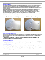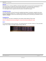
1
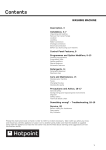
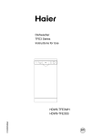
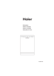
5407525 Issue 1 Jan 2010
ARISTON
Electromechanical
Vented
Tumble Dryers
Models
Covered
Comm.
Code
TVM63X NA
63076
Service
Information
Indesit Company UK Ltd
© 2010 Reg. Office: Peterborough PE2 9JB Registered in London: 106725
Indesit Company
SAFETY NOTES & GENERAL SERVICING ADVICE
1. This manual is NOT intended as a comprehensive repair/maintenance guide to the appliance.
2. It should ONLY be used by suitably qualified persons having technical competence applicable
product knowledge and suitable tools and test equipment.
3. Servicing of electrical appliances must be undertaken with the appliance disconnected (unplugged)
from the electrical supply.
4. Servicing must be preceded by Earth Continuity, Earth Resistance & Insulation Resistance checks.
5. Personal safety precautions must be taken to protect against accidents caused by sharp edges on
metal and plastic parts.
6. After servicing the appliance must be rechecked for Electrical Safety. In the case of appliances
which are connected to a water supply (i.e.: Washing Machines, Dishwashers & Food Centres etc.)
checks must be made for leaks from seals gaskets and pipe work and rectification carried out where
necessary.
7. It can be dangerous to attempt 'DIY' repairs / maintenance on complex equipment and the Company
recommends that any problem with the appliance is referred to its own Service Organisation.
8. Whilst the Company has endeavoured to ensure the accuracy of the data within this publication they
cannot hold themselves responsible for any inconvenience or loss occasioned by any error within.
SERIAL NUMBER / INDUSTRIAL CODE EXPLANATION
Serial Number Example
3 10 02 0895
Four remaining digits = Build number that day 895th built
Third two digits = Day of manufacture 2nd of month
Second two digits = Month of manufacture October
First digit = Year of manufacture 2003
Industrial Code Example
37 24455 0010
Last four digits = 0000 original production.
Other numbers denote major production changes
Second five digits = COMMERCIAL CODE*
* Vital for correct model information and system identification
First two digits = Factory of origin
Service Manual UK
English
2 of 19
Indesit Company
INDEX
Safety & Servicing Notes & Serial Number Information . . . . . . . . . . . . . . . . . . . . . . . . . 2
Serial Number / Industrial Code Explanation . . . . . . . . . . . . . . . . . . . . . . . . . . . . . . . . . 2
Technical Specifications. . . . . . . . . . . . . . . . . . . . . . . . . . . . . . . . . . . . . . . . . . . . . . . . . 4
Machine Function. . . . . . . . . . . . . . . . . . . . . . . . . . . . . . . . . . . . . . . . . . . . . . . . . . . . 5 - 6
Console . . . . . . . . . . . . . . . . . . . . . . . . . . . . . . . . . . . . . . . . . . . . . . . . . . . . . . . . . . . . . 6
Programmes. . . . . . . . . . . . . . . . . . . . . . . . . . . . . . . . . . . . . . . . . . . . . . . . . . . . . . . . . . 7
Component Description . . . . . . . . . . . . . . . . . . . . . . . . . . . . . . . . . . . . . . . . . . . . . . 8 - 11
Timer Sequence Charts . . . . . . . . . . . . . . . . . . . . . . . . . . . . . . . . . . . . . . . . . . . . . . . . 12
Wiring Diagram . . . . . . . . . . . . . . . . . . . . . . . . . . . . . . . . . . . . . . . . . . . . . . . . . . . . . . 13
Dismantling Instructions . . . . . . . . . . . . . . . . . . . . . . . . . . . . . . . . . . . . . . . . . . . . . 14 - 18
Service Manual UK
English
3 of 19
Indesit Company
TECHNICAL INFORMATION
Models Covered
TVM63XNA
63076
White
First Produced
2009
Electrical Rating
115 Volts AC 60Hz
Power Consumption
1.45 kW
Plug Type
USA NEMA 5.15
Cable Length
1.8 Metres
Features
Reversing - Dual Heat - 170 minutes Programme Timer,
Easy Iron (crease removal) and Auto Drying options.
Energy Efficiency
C
Noise
69 dB
Country of Origin
Great Britain
Dimensions
Height
Width
Depth
Weight
850 mm
595 mm
562 mm
35 kg (packed)
Drum
100 Litres / 6Kg Stainless Steel
Drum Speed
55 rpm Reversing
Drying Load
Dry Weight Maximum 6 Kg
Door Operation
Lever operated door catch
Heater Controls
Heat Selection Push Button out for High Heat
Heater*
1300W @ 120V
Control Thermostats*
Cycling Thermostat
One Shot
with DBK Heater
120°C
150°C
Eco Thermostats
40°C Purple Spot
All thermostats are rated at 10 amps
Program Timer
Range up to 170 minutes including 7.5 minutes Cool Tumble.
Two Eco Programmes and Easy Iron (crease removal)
programme.
Motor
Type 353 - Capacitor run, single phase, 2 pole, induction type
Motor Speed
2800 rpm @ 115 Volts AC
Capacitor
25 uF
12 Amps
Group 100
Service Manual UK
with Blasi Heater
106°C
150°C
English
4 of 19
Indesit Company
MACHINE FUNCTION
Cold air is drawn into the dryer cabinet interior through
louvres in the cabinet base, passes through the large hole in
the inner back panel adjacent to the fan and is driven through
the element housing on the inner back panel.
After passing through the element windings and through
holes in the drum back plate into the drum interior, the now
warm air is driven through the load to the front of the drum.
AIRFLOW DIAGRAM
A webbing seal, fixed to the inside of the inner back panel,
prevents warm air being driven into the cabinet interior.
As the drum revolves, the load is tumbled through the warm
air stream, that extracts moisture from the damp fabric.
The now moist and cooled air passes through the filter in the
air duct on the back of the front panel, where any fluff picked
up from the load is removed.
The air then travels through the front to rear air duct, leaving
the dryer at the rear outlet.
If required, a vent hose may be attached to the outlet, to take
exhaust air away from the dryer.
A cut-out on the element housing, cuts the electricity Live supply to the element, if the air temperature
in the housing becomes too high due to a restriction in the air flow, e.g a blocked filter. The cut-out
automatically resets when the air temperature drops to an acceptable level and cycles if the fault
persists.
A second 'one shot' cut-out, mounted alongside the 'auto reset' cut-out, is fitted as a safety device to
break the element Neutral connection, if the air temperature reaches an unsafe level due to failure of
the 'auto reset' cut-out.
There are two thermostats in the front air duct when only one is in use at any one time depending on
which programme is selected. These sense the exhaust temperature rise when the load becomes dry
and energise the timer motor on the main timer. This allows it to advance to cool run.
AUTOMATIC DRYING
To work correctly High Heat has to be enabled and between 3 Kg to 6 Kg of Cottons dried. If smaller or
delicate loads are dried using the automatic setting, erratic results will be achieved.
Automatic Drying Explanation
NOTE: - The heat switch must be set to the high position otherwise there will be no circuit to the timer
motor or heater when the exhaust thermostat signals that the clothes are dry.
continued on next page.....
Service Manual UK
English
5 of 19
Indesit Company
Sequence of Automatic Drying System
•
First 20 minutes, full heat controlled by the timer. This is to pre-heat the clothes and drum before
the exhaust thermostats take control.
•
The timer moves to its next cam position. The timer motor is now disconnected and the dryer
tumbles and heats.
•
When the clothes are dry, the exhaust thermostat opens. This provides a Live supply to the timer
motor. The timer moves to the next cam position.
•
5 minutes of tumbling with the lower element only. The timer moves to the next cam position.
•
Finally 7.5 minutes of tumble with no heat.
CONSOLE
Drying
Guide
Timer / Programmes
Knob
Heat Select
High / Low
The START button begins drying a selected
programme.
The HEAT button selects the drying
temperature.
OUT: Low Heat
IN: High Heat
Start
Button
The Drying Guide allows the customer to
consult a user friendly table of fabric types and
load capacities and shows a guide of the
programmes available.
The TIMER / PROGRAMMES knob sets the
drying time or programme. Rotate it clockwise,
never anti-clockwise, until the indicator is
pointing to the time or programme you want to
select.
Service Manual UK
English
6 of 19
Indesit Company
PROGRAMMES
Program
What it does...
How to set it...
Note:
Timed Drying
up to 170 minutes
Dries wet clothing that will be
ironed, acrylic fibers or small
loads (less than 2 lb / 1 kg).
1. Select required heat setting HIGH
HEAT or LOW HEAT by pressing
the HEAT button.
2. Position the PROGRAMS knob on
the desired time.
3. Press the START button.
Consult suggested drying
times ( see Laundry).
Fabric Care
Heating elements turn
themselves off and clothing is
cooled down.
This is the final phase of all programs.
Approximately 10 minutes before the
finish, the knob advances
automatically to the Air Fluff phase.
After this the clothing is ready to be
taken out.
Always allow the dryer to
complete this phase.
Brief program (approximately
10 minutes) that softens fibers
of clothing that is ready for
ironing.
1. Select HIGH HEAT by pressing the
HEAT button.
2. Position the PROGRAMS knob on
.
3. Press the START button.
! This is not a drying
program ( see below).
Dries completely: your clothes
are ready to be worn.
1. Select HIGH HEAT by pressing the
HEAT button.
2. Position the PROGRAMS knob
on A .
3. Press the START button.
! If you select LOW HEAT,
this program will not dry your
clothes. For Acrylic fibers or
small loads select Timed
Drying.
Air Fluff Phase
Fabric Care
Easy Iron
Fabric Care
A
Automatic
Drying
Regular Cottons,
Permanent Press.
Easy Iron Program
Easy Iron is a short 10 minute program (8 minutes of heat followed by a 2 minute Air Fluff period) which fluffs the
fibers of clothing that have been left in the same position/location for an extended period of time. The cycle relaxes
the fibers and makes them easier to iron and fold.
! Easy Iron is not a drying program and should not be used for wet articles of clothing.
For best results:
1. Do not load more than the maximum capacity.
These numbers refer to the dry weight:
Fabric
Maximum load
Regular Cotton and Regular Cotton mix
5.5 lb / 2.5 kg
P e rma ne nt P re s s
4 lb / 2 k g
D e nim
4 lb / 2 k g
2. Unload the dryer immediately after the end of the program, hang, fold or iron the articles and put them away.
Should this not be possible, repeat the program.
The Easy Iron effect varies from one fabric to the next. It works very well on traditional fabrics like Regular Cottons
or Regular Cotton mix, and less well on acrylic fibers.
Service Manual UK
English
7 of 19
Indesit Company
COMPONENT DESCRIPTION
CONSOLE PANEL
This panel contains the user controls, which consist of a timer knob, for selecting the timed and sensed
drying periods and a push switch for heat selection.
TIMER
The timer system is made up from two timers, one mounted on the console and one in the base of the
machine.
Timer 1 controls the motor and heater. This has a spindle to which a knob is attached to enable the user
to select the required programme. Timer 2 controls the motor reversing; this is mounted on the kickstrip.
The dryer must be set to the high heat position for the Eco drying system to operate failure to do so will
cause the timer to advance to cool run without drying the load.
Timer 1 - Programme Timer
Mounted on the console, the timer is used to control the motor and heating during the drying
programmes. The timer incorporates a timed cycle with 170 minutes of heated drying followed by a 7.5
minute cool run.
One ’Eco' programme is incorporated with an automatic programme to provide heated drying until a
thermostat operates (when the load is dry), the timer then advances to a 7.5 minute cool run.
The cam of this timer is held on the heated part of the cycle by cutting the circuit to its motor.
The dryer motor continues to be reversed by timer 2. When the load is dry, a thermostat in the front duct
of the dryer operates which powers the motor of timer 1 and this allows the timer to advance to
cool run. Timer 2 reverses the motor direction approximately every 2.5 minutes.
An optional crease removal programme is provided, which consists of 7.5 minutes of heat and motor
followed by a cool tumble period of 2.5 minutes.
Timer 2 - Reversing Timer
Mounted on the base panel, the timer is used to control the reversal of the motor during the drying
programmes. The timer reverses the motor direction every 2.5 minutes.
HEAT SWITCH
Normally open push-push switch. The switch locates into the facia moulding and it allows the user to
choose high or low heat settings. By consulting the wiring diagram, it can be seen that by operating this
switch, either all or half of the heater unit is selected.
For full heat switch is in the IN position and low heat in the OUT position.
High heat must be selected for the auto-drying programmes to operate, if low heat is selected the dryer
will advance to cool run without drying the load.
DOOR
A plastic moulded chassis with a glass bowl retained by plastic mouldings.
continued on next page ....
Service Manual UK
English
8 of 19
Indesit Company
DOOR INTERLOCK
Bitron Door Lock Operation
door hook
solenoid
bistable cam
latch
Switch blade lever
Door Open - Dryer Off
Trying to turn the machine on with the door open, the solenoid is unable to operate the bistable cam to
close the contacts, because it is locked by the latch.
Door Closed - Dryer Off
Closing the door, the latch (now rotated by the door hook) allows the movement of the bistable cam, but
the dryer is still OFF until the solenoid is energised.
Door Closed - Dryer On
Turning the machine on with the dryer door closed, the solenoid pushes the bistable cam (freed by the
latch) allowing the closing of the contacts.
Door Opened During Drying
When the door is opened during drying, the dryer will turn off automatically by the latch in its back
rotation, this pushes back the bistable cam towards the solenoid, opening the contacts.
Re-closing the door will not restart the machine until the machine is turned back on.
Safety Function
If the latch is accidentally rotated by the customer with the door open, the machine will not start. Without
the latch in position, the latch rotates 30% further and sets the bistable cam in its safety position. The
safety position will not allow the machine to start. The door will need to be manually repositioned to reset
by a Service Engineer.
DRUM
The drum comprises of a stainless steel wrapper with a zinc-coated front and rear body and two
removable plastic lifters. The rear of the drum is perforated to allow the passage of air. Fixed to the rear
pressing is a support shaft, which runs in a bearing located in the rear panel of the dryer.
A drive pin and collar on the drum shaft prevents forward thrust during use. The large front flanged
aperture rotates on bearing pads.
Service Manual UK
English
9 of 19
Indesit Company
HEATER ELEMENT
The element comprises of front and rear pressings spaced apart with Mica type insulating material.
Through the insulating pieces are 4 runs of coiled resistance wire supported from end to end by
insulating material. High temperature insulated wires are crimped to the ends of the resistance strips to
complete the circuit.
Note: Heater assemblies manufactured by Blasi and DBK are interchangeable if replaced as an
assembly. Both types are used in production. The service replacement type is a DBK heater.
The thermostats are NOT interchangeable - DBK uses a 120°C, and Blasi uses a 106°C device.
The correct thermostat kit MUST ALWAYS be fitted - depending on the heater fitted.
The heaters can be identified by the appearance of the indentations in the rear cover - refer to the
photos below.
Blasi Heater Cover - with 2 pips
DBK Heater Cover - with 4 pips
SAFETY CUT-OUT (BLUE SPOT)
This device is a disc type thermostat set to operate at 150°C it is used as a safety device. It is positioned
above the element, to the right of the cycling thermostat on the element housing. If this device fails it
cannot be reset.
IF THIS DEVICE OPERATES, IT SHOULD ALWAYS BE REPLACED TOGETHER WITH THE
CYCLING THERMOSTAT (see next paragraph).
CYCLING THERMOSTAT
The cycling thermostat is mounted adjacent to the safety cut-out, is designed to open at 120°C (DBK)
or 106°C (Blasi). It limits the temperature of the heat entering the drum.
ECO THERMOSTATS
These are of self-resetting closed disc construction, mounted in the front air duct. They control the timer
motor on timer 1. When the load is dry, the selected thermostat operates and powers the timer motor;
this allows the timer to advance to cool run. The Full load thermostat (E) is designed to open at 55°C
and the half load (e) is designed to open at 60°C.
Service Manual UK
English
10 of 19
Indesit Company
MOTOR
A two pole P.S.C running at 2800 rpm with the impeller fitted to the rear end of the shaft and the drive
belt running directly in grooves in the front end of the shaft. It is protected from overload by a
self-resetting internal cut-out which interrupts the electrical supply to the windings.
It is used together with a capacitor that is mounted on the base of the dryer.
DRUM REAR SEAL
This unit comprises of a ring of foam with a webbing bearing face. Lubrication is applied to the drum
where the webbing surface runs, to reduce noise and wear. The seal reduces air losses at the rear of
the drum. The joints in the foam are sealed with glue and the joints in the webbing are stitched to further
reduce air leakage.
DRUM EARTH
The earthing on the drum is achieved by the teardrop shaped bearing fixing screw.
Note: To maintain the drum earthing the correct screw must always be used.
BELT
A 9 rib belt has been used in production. The length stamped on the belt is 1860 mm. This is the fitted
length. Prior to fitting, the length is approximately 1805 mm.
Service Manual UK
English
11 of 19
C 3 - C 1 (C 3 - C 4)
sta t s elect
A 9 - A 1 1 (A 1 - A 2)
T im e r & M oto r
A 1 - A 3 (B 3 - B 4 )
B u zze r
B 1 0 - B 1 1 (B 2 - B 1 )
H ea ter
B 3 - B 1 (A 4 - A 5 )
7.5 mins
38
39
40
41
42
43
44
45
46
47
48
49
50
51
52
53
54
55
56
57
58
5 min
5 min
5 min
5 min
2.5 min
2.5 min
59
2.5 min
37
5 min
20 mins
36
5 min
30 mins
35
5 min
40 mins
34
5 min
50 mins
33
5 min
60 mins
32
5 min
70 mins
80 mins
90 mins
100 mins
110 mins
120 mins
130 mins
31
5 min
30
5 min
29
5 min
28
5 min
27
5 min
26
5 min
25
5 min
24
5 min
23
5 min
22
5 min
21
5 min
20
5 min
19
5 min
18
5 min
17
5 min
16
5 min
15
2.5 min
14
2.5 min
13
2.5 min
12
2.5 min
11
2.5 min
10
2.5 min
9
2.5 min
8
2.5 min
7
2.5 min
6
2.5 min
4
2.5 min
5
2.5 min
3
2.5 min
140 mins
A u to
T im e d
2
2.5 min
1
C 3 - C 2 (C 3 -C 5 )
*1
*1
*1
*1
12 of 19
3
N ote *1 : th e prog ram m e c am s ho uld a dva nc e to the ne xt step be fore th e tim er sto ps
Reversing Timer Sequence Chart
switch
switch
no.
1
2
3
4
5
6
7
8
9 10 11 12 13 14 15 16 17 18 19 20 21 22 23 24 25 26 27 28 29 30 31 32 33 34 35 36 37 38 39 40 41 42 43 44 45 46 47 48 49 50 51 52 53 54 55 56 57 58 59 60
1 to 2 secs - >
motor cw
motor acw
< - - - - - - - 148 seconds +/-2 - - - - - - - - - - - >:
< - 1 to 2 seconds
a - a1
a - a0
< - - - - - - - - - - - - - - - - - - - - - - - - 300 seconds - - - - - - - - - - - - - - - - - - - - - - - - - - - >
Switch Ratings
CONTACT / TERMINAL
RATING
COMPONENT
SWITCHED
MAX.
CURRENT
C3 - C2
16(4)A
TIMER MOTOR
<1A
C3 - C1
16(4)A
TIMER MOTOR
<1A
A1 - A3/A4
16(4)A
MOTOR & HEATER
10A
B3/B4 - B1
16(4)A
HEATER
9.2A
Invensys EC
60
Indesit Company
Service Manual UK
Main Timer
Sequence Chart
English
Indesit Company
PINK
160025148
TIMER - EC
A11
BROWN
160025152
ORANGE
B5
BLUE
B8
B9
HEAT SWITCH
BLUE
ORANGE
M ORANGE
BROWN
M BROWN
BLACK
160024277
M
WHITE
START
SWITCH
REVERS'G
TIMER
THERMOSTAT
EARTHING
BRACKET
ORANGE
WHITE
M
B11
B12
ORANGE
160020222
VIOLET
160020223
160020224
B9/
B10
WHITE
BLUE
PB
TM
RED
PB
PB
CAPAC
-ITOR
BROWN WITH
BOOT
PINK
M BLACK
160025149
ORANGE
160020222
PTC
SOLENOID
4
A11
ORANGE
Programme
Timer Wiring
BLACK
BLACK
13 of 19
VIOLET
160020404
A12
BLUE
B7
B4
A12
160030301
B6
BLUE160020201
TM
3
ORANGE
LOWER
HEATER
UPPER
BLACK
160020201
B11
B10
BLACK
ORANGE
160025154
B1
ONE SHOT
CUT OUT
RED
160025153
B3
A3
A9/A10
5
REAR VIEW OF
CONNECTOR FOR HEATER
BROWN
A4
A1
CYCLING
STAT
= INSULATOR
M = MALE TAB
PB = PIGGY BACK
(UPPER) ENERGY
SAVE STAT-HALF
(PURPLE SPOT)
Service Manual UK
WIRING DIAGRAM - TVM63X NA
RED
1
2
3
4
5
6
7
8
9
10 11 12
B
1
2
3
4
5
6
7
8
9
10 11 12
A
BLUE
MOTOR
MAINS CONNECTION
RED
160025151
L1
BLACK
WHITE
BLACK
160025150
VIOLET
N
WHITE
E
GREEN
16002514202
WIRING DIAGRAM
120 VOLT NA/UL VENTING
English
Indesit Company
DISMANTLING INSTRUCTIONS
SAFETY NOTES
1. Ensure that the machine is unplugged before commencing any work.
2. Beware of sharp edges on metal panels and pressed parts.
A
1.
2.
Top Cover
Remove the 2 screws securing the top cover to the back panel.
Slide the top cover back and lift clear of the console.
B
1.
2.
3.
4.
5.
6.
7.
Console Panel
Remove the top cover as in (A).
Remove the 2 screws securing timer mounting plate to the console and unclip from the console.
Disconnect the wiring to the option switches, noting the connections.
Unclip the start relay from the console.
Remove the 2 screws securing the console to the side panels (top of console).
Remove the screw on the right hand side securing the front panel to the side panel.
Lift the locking tabs securing the console to the front panel and lift the console clear of the front
panel.
Remove the timer knobs from the console by depressing the locking tabs.
Replace in reverse order.
8.
9.
C
1.
2.
3.
4.
5.
Programme Timer
Remove the top cover as in (A).
Remove the 2 screws securing the timer mounting plate to the console and unclip from the console.
Remove the screws securing the timer to the timer mounting plate.
Note the connections and disconnect the wiring to the timer.
When refitting the timer mounting plate to the console it may be easier to remove the timer knobs
from the console to aid reassembly.
D
1.
2.
3.
4.
Door Lock
Remove the top cover as in (A).
Remove the right hand side panel (F).
Disconnect the wiring.
Slide the switch to release it from the front panel.
E
1.
Option Switches
Remove the switch caps by gripping with pliers and pulling the cap off the switch shaft (care should
be taken to avoid damage to the cap when removing).
Note the connections and disconnect the wiring from the switch.
Depress the locking tabs to remove the switch from the console.
2.
3.
Service Manual UK
English
14 of 19
Indesit Company
F
1.
2.
3.
4.
5.
6.
Side Panels
Remove the top cover as in (A).
Remove the plinth by pulling forward.
Remove the screw behind the plinth.
Remove the screw securing the side panel to the front panel.
Remove the 4 screws securing the side panel to the rear panel.
Pull the side panel backward to disengage from the lugs on the base panel.
G
1.
2.
3.
4.
5.
6.
7.
Front Panel & Air Duct
Remove the top cover as in (A).
Remove the console complete as in (B7).
Remove the plinth.
Remove the 4 screws securing the front panel to the base panel.
Disconnect the wiring to the air duct thermostat(s).
Disconnect the wiring to the door switch.
Remove the 2 screws securing the left hand side panel to the front panel.
I
1.
2.
Energy Save
Remove the right hand side panel as in (F) above, or the front panel as in (G).
Disconnect the thermostat wiring and remove the 2 screws fixing the thermostat to the air duct.
J
1.
2.
3.
4.
Door Switch / Interlock
Remove the top cover as in (A).
Remove the right hand side panel as in (F).
Disconnect the wiring to the switch.
Using the button removal tool Part No. C00222677 (5600127), depress the 2 plastic locating pips
on the door switch (taking care not break lugs) and slide the switch towards the door seal to
disengage from the front panel.
K
1.
2.
3.
4.
Door Seal
Remove the front panel and air duct as in (G).
Remove the 4 screws securing the air duct to the front panel and separate the air duct from the
front panel.
The door seal can now be removed from the front panel.
Replace in reverse order.
L
1.
2.
3.
4.
5.
6.
Door
Open the door and remove the 4 screws securing the door assembly to the front panel.
Remove the complete door from the front panel.
Remove 1 screw securing the door latch to the door.
Remove the screw behind the door latch, securing the door handle to the door.
Remove the 6 screws securing the two halves of the door assembly.
The door trims can now be split giving access to the door bowl, handle and door hinges.
Service Manual UK
English
15 of 19
Indesit Company
M
1.
2.
Door Hinges
The door must be removed and split as in (L1) - (6) above.
Turn the door hinges inwards and slide the hinge upwards
to disengage from the rear trim moulding as in Fig 1.
Fig. 1
N
1.
2.
Front Bearings
Remove the front panel as in (G).
Spring the fixing lug out of the open slot in the
bearing mounting bracket and slide the pad along
the bracket to free the other lug as illustrated.
O
1.
2.
Drive Belt Removal - if not broken
Remove the right hand side panel as in (E).
Place the end of the Special Tool, Part No. C00142716 (5600266), into the slot in the base of the
dryer.
Bearing Pad
Mounting Bracket
Special Belt Fitting Tool
Part No. C00142716
3.
Locate the pegs of the tool into the belt and apply downward pressure to release the belt from the
motor shaft.
Belt
Motor
Motor Shaft
Special Tool
Apply
downward
pressure
4.
5.
Release the top fixings of the front panel and ease away from the drum.
Slide the belt off the drum and pass between the drum front and the front panel.
Service Manual UK
English
16 of 19
Indesit Company
3.
4.
Drive Belt Fitting
Slide the new belt onto the drum and replace the front panel.
Place the Special Tool, Part No. C00142716 (5600266), onto the inside edge of the new belt (cut
out section of tool facing the drum).
Ease the special tool onto the motor shaft as far as possible.
Rotate the special tool in either direction to refit the belt onto the shaft.
P
1.
2.
3.
Capacitor
Remove the right hand side panel as in (F).
Note the wiring connections and disconnect the leads from the capacitor terminals.
Carefully lay the dryer on its back and remove the capacitor securing nut.
Q
1.
2.
3.
4.
5.
6.
7.
Drum Assembly
Remove the top cover as in (A)
Remove the console as in (B)
Remove the front panel as in (G).
Remove the right hand panel to make drum removal easier.
Remove the rear bearing cover - 2 screws.
Remove the rear bearing fixing screw.
Remove the drive pin and shaft collar.
Note: When reassembling, a new drive pin must be fitted.
Remove the rear bearing.
Pull the drum clear of the rear panel.
1.
2.
8.
9.
R
1.
2.
3.
4.
5.
Heating Assembly & Thermostats
Remove the right hand side panel as in (F).
Disconnect the wiring to the heater assembly (multi-pin connector).
Remove the bearing cover.
Remove the 8 screws securing the heater assembly to the rear panel.
Remove the 2 screws retaining the element and thermostats to the heater cover.
If replacing the thermostats both the cycling and one-shot thermostat MUST be replaced should
either fail.
NOTE: - When refitting the heater cover, ensure the heater wiring Is not trapped between the
inner and outer rear panels.
S
1.
2.
3.
4.
Rear Bearing
Remove the plastic, fan shaped bearing cover.
Remove the drive pin.
Remove the bearing fixing screw.
Slide the bearing off the drum shaft.
Note: To maintain the earthing of the drum, the correct bearing fixing screw MUST be used.
Service Manual UK
English
17 of 19
Indesit Company
T
1.
2.
Rear Seal
Remove the drum as in (Q).
Remove the rear seal and clean any remnants of the seal and adhesive from the inner face of the
inner back panel. Fit the new seal using adhesive Part No. C00981027 (981027).
U
1.
2.
3.
Motor
Remove the right hand side panel as in (F).
Remove the heater cover - 8 screws.
Remove the 2 fans from the motor hub - 3 hex head screws.
Note: The inner and outer fans are DIFFERENT.
Ensure fans are reassembled in the correct order.
Note the wiring connections and disconnect the motor at the in-line connector and the capacitor.
Disengage the drive belt from the motor shaft as in (O2).
4.
5.
Motor Fans - Orientation
Inner
Raised
Hub
Outer
Recessed Hub
Inner
6.
7.
Outer
Remove the 3 hex head screws securing the motor to the motor cradle.
Remove the 2 screws securing the cradle to the base panel if necessary.
Note: When refitting the heater cover ensure that the heater wiring is not trapped between
the heater cover and rear panel.
Service Manual UK
English
18 of 19
Indesit Company
Service Manual UK
English
19 of 19