1
T
OWNERS
MANUAL
I®
P OFESSIONAL
ROUTER CENTER
Model No.
171.254841
CENT
O
P OFESlONAL
FRESADO
MANUAL DEL
PROPIETARIO
Modelo No.
171.254841
DE
I
71255
0WNER8 MANUAL
WARNING:
Before operating
product, read this
manual and follow
all its Safety
and Operating
Instructions.
ADVERTENCIA:
Antes de utilizar
este producto, lea
este manual y
siga todas las
instrucciones
de
uso y seguridad.
Sears,
171.254841
01/99
Roebuck
Printed
in
U,S.A.
and
Hechoen
Co.,
los
Estados
Hoffman
Unidos
Estates
IL 60179
USA
General
Safety
Additional
Safety
Introduction
Optional
Instructions
Assembly
Installation
Instructions
for Router
Table ..........................................
.....................................................................................................
Router
Unpacking
for Power Tools ...............................................
Table Accessories
and Checking
Contents
3
4
5
..............................................................
6
..............................................................
6
.........................................................................................................
7
.....................................................................................................
14
.......................................................................................................
18
Parts List .......................................................................................................
27
Operation
SAFETY
This manual
contains
informa-
tion that is important for you to
know and understand. This
information
relates to protect-
ing YOUR SAFETY and
PREVENTING
EQUIPMENT
PROBLEMS.
To help you recognize this information,
we use
symbols to the right. Please
read the manual and pay
attention to these sections.
,_WARNING
GUIDELINES
- DEFINITIONS
[_DANGER
URGENT
SAFETY
A HAZARD
SERIOUS
THAT
INJURY
_CAUTION
]
INFORMATION
WILL
-
INFORMATION
CAUSE
OR LOSS
DAMAGE
IMPORTANT
SERIOUS
SAFETY
THAT
INJURY
NOTE
INFORMATION
MIGHT
PREVENTING
OF LIFE
I _WARNING
A HAZARD
FOR
TO EQUIPMENT
CAUSE
OR LOSS
-
INFORMATION
PAY SPECIAL
THAT
]
YOU SHOULD
ATTENTION
TO
OF LIFE
Failure to heed all safety and operating instructions and warnings regarding use of this
product can result in serious bodily injury.
1. Know your power tool
Read the owner's manual carefully. Learn its application and limitations as well as the specific potential
hazards peculiar to this tool.
2. Ground all tools (unless double insulated)
If tool is equipped with an approved three-conductor
cord and a three-prong grounding type plug, it
should be plugged into a three hole electrical receptacle. If adapter is used to accommodate a two-hole
receptacle, the adapter wire must be attached to a
know n ground (usually the screw securing receptacle
cover plate). Never remove third prong. Never connect green ground wire to a terminal.
3. Keep guards in place
Maintain in working order, and in proper adjustmeni
and alignment.
4. Remove adjusting keys and wrenches
Form a habit of checking to see that keys and
adjusting wrenches are removed from tool before
turning it ON.
5. Keep work area clean
Cluttered areas and benches invite accidents. Floor
must not be slippery due to wax or sawdust.
6. Avoid dangerous environment
Do not use power tools in damp or wet locations or
expose them to rain. Keep work area welt lighted.
Provide adequate surrounding work space.
7. Keep children away
All visitors should be kept a safe distance from
work area.
8. Make workshop child-proof
Use padlocks, master switches, or remove starter keys.
9. Do not force tools
They will do the job better and safer at the rate for
which they were designed.
10. Use the right tool
Do not force tool or attachment to do a job it was not
designed to perform.
11. Wear correct apparel
Do not wear loose clothing, gloves, neckties or jewelry (rings, wristwatches) that may get caught in
moving parts. Non-slip footwear is recommended.
Wear protective hair covering to contain long hair.
Roll long sleeves above the elbow.
12. Use safety goggles (Head Protection)
Wear safety goggles (must comply with ANSI
Standard Z87.1) at all times. Also, use face or dust
mask, if cutting operation is dusty, and ear protectors (plugs or muffs) during extended periods of
operation.
13. Secure work
Use clamps or a vise to hold work when practical.
It's safer than using your hands, and both hands are
free to operate tool.
14. Do not overreach
Keep proper footing and balance at all times.
15. Maintain tools with care
Keep tools sharp and clean for best and safest performance. Follow instructions for lubricating and
changing accessories.
16. Disconnecttools beforeservicing
Beforeservicing,whenchangingaccessories
such
as blades,bits,cutters,etc.
17.Avoidaccidentalstarting
Makesureswitchis inOFFpositionbeforepluggingin.
18. Userecommendedaccessories
Consulttheowner'smanualfor recommended
accessories
andfollowthe instructions.
Theuseof
improperaccessories
maycausehazards.
19. Neverstandon tool
Seriousinjurycouldoccurif the toolis tippedor if
thecuttingtoolis accidentally
contacted.DONOT
storematerialsaboveor nearthetoolmakingit necessaryto standonthe toolto reachthem.
20,Checkdamagedparts
Beforefurtheruseof thetool,anyguardor otherpart
thatis damagedshouldbecarefullycheckedto
ensurethatitwill operateproperlyandperformits
intendedfunction.Checkforalignmentof moving
pads,bindingof movingpads,breakageofparts,
mounting,andanyotherconditionsthatmayaffect
itsoperation.Aguardor anyotherpartthatis damagedshouldbe properlyrepairedor replaced.
21. Direction
of feed
Feed work into a blade
23. Keep
24. Store
When
hands away
idle tools
5. IAI
AIAWARNING
II Vibrations, caused by the router
during use, can cause fasteners to become loose,
Before use and periodically during use, check all fasteners to make sure that all are tight and secure.
6. Do not use this product until all assembly and
installation steps have been completed. Make sure
you have read and understood all safety and operational instructions in this manual and the router
owner's manual.
7. Make sure that the router bit is properly positioned
and clamped in the router before making any cuts,
8. Do not use the router table as a workbench or
work surface. Doing so may damage it, causing it to
be unsafe to use. A workbench should be used for
this purpose.
from
AGAINST
cutting
not in use. tools should
the direc-
area
be stored
or locked-up
place - out of reach
25. Do not abuse cord
in dry, high
of children.
Keep cord away from heat, oil and sharp edges.
26. Outdoor
extension
cords
When
cords
tool is used outdoors,
use only extension
suitable for use outdoors
and so marked.
27. Never
use
in an explosive
atmosphere
Normal sparking of the motor could ignite fumes,
flammable
liquids, or combustible
items.
28. Drugs,
alcohol,
medication
Do NOT operate tool while under the influence of
drugs, alcohol, or any medication.
Read and Understand
completely
1. Always wear eye protection that complies with
ANSI Standard Z87.1.
2. Noise levels vary widely with location. To avoid
possible hearing damage, wear ear plugs or ear
muffs when using your router table for long periods
of time.
3. For dusty operations, wear a dust mask along with
safety goggles.
4. Follow the instructions in your router owner's
manual.
or cutter
tion of rotation of the blade or cutter only.
22. Never leave tool running
unattended
Turn power OFF. DO NOT leave tool until it comes
to a complete
stop.
this instruction book
BEFORE using this product.
9. This product is designed for cutting flat workpieces. Do not cut or attempt to cut workpieces that
are not flat.
10. This product is designed for cutting wood workpieces only. Do not use to cut metal or other nonwood materials.
11. The use of auxiliary in-feed and out-feed supports is strongly recommended when routing long
workpieces. Otherwise those workpieces can cause
the router table to tip over.
12. Keep hands clear of the router bits and working
area.
13. Make and use a push stick to move small workpieces across the cutting area.
14. Clean the router after use. The use of a wet!dry
vac or vacuum equipment is recommended.
15. Always make sure that work surface of the router
table is clean and free from dust, chips, and foreign
particles that can interfere with the cut you are going
to make. The use of a wet/dry vac or vacuum equipment is recommended.
16. The fence that comes with the router table has a
dust collector (if available on enclosed model) to
which a wet/dry vac can be attached. The use of a
wet/dry vac is recommended when using the fence.
17. Check the function of the guard before each
use. Remove all dust, chips, and any other foreign
particles
that can affect its function. Adjust the
guard height so that it clears the router bit or the
workpiece,
whichever
is taller.
18.
/A/Lm WARNING
J Never
put your
fingers
under
the guard when the router is plugged into an electrical outlet or when the router bit is rotating.
19. Always use the fence to guide the workpiece.
DO NOT work freehand
unless piloted router bits are
being used.
20. Always use piloted router bits for freehand
routing of irregularly shaped workpieces.
21. Always feed the workpiece
AGAINST
the rotation
of the cutter or router bit.
22. Router bits are extremely
sharp:
when handling and using them.
be extra
careful
down position (such as on a router table), will drop
or fall out of the router base when the base clamp is
loosened
to adjust height or depth of cut, Therefore,
Professional
Router
Table comes
with the following:
• A unique 4" high unitized fence with fence guides
that provide parallel movement.
• Scales molded into the _able top that provide fast
and accurate fence adjusT, merit for making the fo!lowing items:
• tenons
o
•
°
•
sliding dovetail joints
tongue and groove joints
edge and end grain cuts
face cuts
• The unique fence also al!ows
additional
routing operations:
• veining
° fluting
touch anything but the switch when doing this.
NEVER reach under the router table for any reason
when the router is running, except to turn it OFF.
26.
,_WARNING
sure the router
rotating,
you to perform
these
Before
is turned
and the power
making
any cut, make
OFF. the router
cord
is unplugged
bit is not
from
the
electrical outlet. Then, make absolutely
sure that the
guard clears the router bit and the workpiece.
A trial
pass, with the router turned OFF and the router bit
not turning,
23. Make sure that the router bits being used are
sharp or have been properly resharpened.
This will
permit fast, efficient, and SAFE routing.
24. Some routers, when positioned
in an upside
Your Craftsman
it is extremely
important
to suppod the router from
below when making these adjustments
or whenever
the base clamp is loosened.
25. Always look under the router table at the router
switch when turning the router ON or OFF. DO NOT
27.
is strongly
I,A]I,luLWARNING
recommended.
j Never leave the router
table
unattended while the router is running. Turn the router
OFF before leaving the router table for any reason.
° making crown molding
. making cuts up to 2-1 2" from the edge of the
workpiece toward the center of the workpiece
° A specially designed push block with a quick clamp
for back-up. It can clamp workpieces up to 4" wide
for end grain or edge routing.
• An accurate adjusting jointing fence that is quickly
adjustable to the proper depth of cut.
"A dust collector port on the fence to which most
wet/dry vacs can be attached.
• Extensions that provide a large work surface.
,, A switch, with overload protection, to control turning
the router ON and OFF. An additional accessory,
such as a wet/dry vac, can also be plugged into the
second receptacle.
° A floor stand for mounting the router table.
9-25333CraftsmanProfessionalRouterAdapter
Plate,for mountingnon-Craftsman 1/4" and 1/2"
shank routers to the router table. The holes for
mounting the router must be located and drilled by
the user. The fasteners for mounting the router to
the adapter plate are not included and must be
obtained separately.
9-25468 Craftsman
Guide Master Router Table
Push Shoe, aids in push shoe and hold down operations, aids in accurate measurement and router
table setup, transforms into a miter gauge, and gives
quick setup for 1/2" sliding dovetail joints.
9-25332 Craftsman Router Table Guide Bushing,
follows templates for repetitive routing of certain
shapes.
Refer to Parts List on Page 27.
. Ii,_WARNING
If ANY of the parts is missing,
DO NOT attempt to assemble, install, or use your
router table until the missing parts have been found
or replaced and your router table has been properly
and correctly assembled per this manual.
• Contact your local Sears Retail Outlet for missing
or replacement pads.
, In order to simplify handling and to minimize any
damage that may occur during shipping, your router
table comes unassembled.
° Separate all parts from the packaging materials
and check each part against the illustrations and the
parts list at the end of this manual, to make sure that
all parts have been included. Do this before discarding any of the packaging material.
TOOLS
REQUIRED
recesses
o Slotted and Phillips screwdriver.
, Small or medium sized adjustable
(or a set of nutdrivers).
• Hammer•
ROUTER
]
NOTE
] There
in the switch
are two hex shaped
case
into which
"KEPS" nuts are placed, with the toothed washer
side of the nuts facing out of the recesses.
5. Securely TIGHTEN all fasteners.
6. Assemble the remaining three table legs to the
table top using four #10-32 x 1/2" long truss head
wrench
TABLE
machine
screws
and four #t0-32
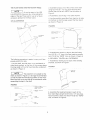
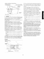
1. Lay the router table, top down. on a flat surface so
that the orientation of the table is as shown in Figure 1.
(BACK of the table is facing toward you.)
for each leg, as shown in Figure
the table is facing toward you.)
FIGURE 1
FIGURE 2
-
qOb-Eq
TABLE
!
/-_
LEG
/_
"!0
J
32 X 1 2"
TRUSS
SCREW
_J
7. Securely TIGHTEN
....
_
_. L_'-'.._ _,
....
of
LONG
SWITCH
HEAD MACHINE
(TYPICAL!
_I0 32 HEX
{TYPICALI
_
hex "KEPS •' nuts
2. (The BACK
all fasteners.
'\
•"
the hex
KEPS
RO_,-SR
T&BLE
bIUT
--
j÷ i'
"
_--<----
" E_ _..'--"
....
_--=I032
>_UT
7 :,_,/_
.
'"
....1...---.:,
_E_
-"=C'-
KEU5
DE,.
°
1
/
BACK
C:ROUTER
-&BLE
2. Assemble a table leg to the table top using four
#10-32 x 1/2" long truss head machine screws and
four #10-32 hex "KEPS" nuts, as shown in Figure 1
and the Figure t, Assembly Detail. (Leg is shown in
the UPPER LEFT corner of router table.) DO NOT
TIGHTEN at this time.
3. Position the switch against the leg, as shown in
Figure 1, Assembly Detail.
4. Secure the switch to the leg and table top using
two #10-32 x 1/2" long truss head machine screws,
and two #10-32 hex "KEPS" nuts.
FIGURE 1, ASSEMBLY
_
10 32 X 1,2" LONG
TRUSS
HEAD MACHINE
'
TABLE
/!\
LEG
\
\
_--
--
.
_
_
SCREW
ITYPICAL)
ROUTER
TABLE
--
_
'
,10 32 HEX
"KEPS"
--
_10 32 X 1 2 LD_4G
TRUSS HEAD ),!ACHtNE
TABLE
LEG
SCREW
TO THE ROUTER
TABLE
3
_10 32 _EX
ITYI_IB ALl
--_
KEPE
!;_jT
--
-\
\
c-,+
ROL'-En
-*t. RLE
_EG
-
-- "10 32 X _ 2 LONG
TRUSS HEAD &4,mCHI_4E
SCREW
+TY_!CAL ,
/_
NUT
.....
,_ f',.":--r---,_ .... ,_
,'
"
__
L.
_
__-
---=- _ ......
:;-,
"_
_'7;_" "_-1">
_ * - _
:" =
-"
.
"
-
_
{,
"' :
....
'L
__"-
EXTE tiSIOt't
--
...... -_L.-'-t-EXTENSIOn,
/
ROUTER
_--
S\%ITCH
\_
--
'_
%,
TABLE
v DETA'L
BRACE
":
,10 32 HEX
NUT
INOT
KECE
_lS BLEI
f_
ASSEMB:_
BR_CE
"-
/_
_
RIGHT SIDE
EXTENS!ON
/
_'
ITYP!CALI
•
MACHINE
SCREW
NUT
(TYP CALl
T'r clCAL;
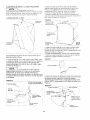
1. Position the router table so that the orientation is
as shown in Figure 3 and Figure 3, Assembly Detail.
(FRONT of the table is facing toward you.)
2. Position one of the extensions alongside the right
side of the table top so that the miter slot in the
extension lines up with the miter slot in table top.
3. Assemble a #10-32 x 1/2" long truss head
machine screw and a #10-32 hex "KEPS" nut at
each of the holes in the extension, as shown in
Figure 3 and Figure 3, Assembly Detail. DO NOT
FIGURE
DETAIL
=/
ROUTER
EXTENSIONS
&
ROUTER
__
BACK OF
ROUTER
TABLE
'10 32 HEX "KEPS
NUT _NOT _ IE!BLE
--z
_'1032X
12
LONG
TRUSS HEAD MACHI_4E
SCRE','v Ib_OT VfSfBLE
FIGURE
3, ASSEMBLY
DETAIL
8. Assemble
a #<10-32 x 1/2" long truss head
machine screw and _'10-32 hex "KEPS" nut at each
of the holes in the extension,
as shown
in Figure
DO NOT tighten fasteners
at this time.
9. Assemble
the other LEFT SIDE extension
4.
brace
(29LCN-989)
to the table leg and the extension
using #10-32 x 1/2 long truss head machine
screws and a #10-32
hex "KEPS" nuts, as shown
Figure 4.
10. Assemble
one of the RIGHT
SIDE
in
extension
braces (29LCN-988)
to the table leg and the extension using #10-32 x 1/2" long truss head machine
screws and #10-32
hex "KEPS" nuts. as shov,.n in
ASSEMBLY
tighten
I
fasteners
NOTE
CETAL
at this time.
I
I The extensions
are identified
with
either an "R" for the RIGHT SIDE extension (29LCN988) or an "L" for the LEFT SIDE extension
(29LCN989). The "R" or the "L" will be found on one of the
bent down or bent up ends of the extensions.
4. Assemble
one of the RIGHT SIDE extension
braces (29LCN-988)
to the table leg and the extension using #10-32 x 1/2" long truss head machine
screws and #10-32 hex "KEPS" nuts, as shown in
Figure 3 and Figure 3, Assembly
Detail.
5. Assemble one of the LEFT SIDE extension
braces
(29LCN-989)
to the table leg and the extension using
#10-32 x 1/2" long truss head machine screws and
4'10-32 hex "KEPS" nuts, as shown in Figure 3.
6. While pressing down on the extension,
tighten all
of the fasteners
using the following sequence:
a. Those holding the extension to the table top.
b. Those holding the extension
braces to the legs.
c. Those holding the extension
braces to the
extension.
7. Position the other extension alongside
the left side
of the table top so that the miter slot in the extension
lines up with the miter slot in table top, as shown in
Figure 4.
FIGURE 4
Figure 4.
11. While pressing down on ti_e extension,
tighten all
of the fasteners
using the following sequence:
a. Those holding the extension
to the table top.
b. Those holding
c. Those holding
extension.
the extension
the extension
braces
braces
to the legs.
to the
12. Set the router table right-side-up
on the floor and
check that the extensions
are parallel and even with
or slightly below the top of the table.
In no case are the extensions
to be higher
than
or above the top of the table top. They could
interfere
with the workpiece
during
routing
and
cause a condition
that can result
in possible
serious
injury.
13. If the extensions
are higher and!or not parallel.
then loosen the fasteners
hoi0ing the extensions
to
the braces and the table top. and reposition
the
extensions
so that they are parallel.
14. Securely TIGHTEN
all fas:eners
again.
15. To double check, slide a fat piece of wood along
the top of the table in all directions.
Make sure that
the edge of the wood moves freely
ing the edges of the extensions,
without
contact-
THE
FLOOR
STAND
AND
NOTE
THE
ROUTER
TABLE
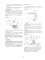
As can be seen in the LEG
ILLUSTRATION, there are four holes along the
edges of the leg. These are for use on a future
accessory product for the floor stand.
LEG ILLUSTRATION
2. Assemble a leg to one of the corners of the shelf
using four #10-32 x 1/2" long truss head machine
screws and #10-32 hex KEPS"
nuts, as shown in
Figure
5.
3. Assemble
leg in the same
manner,
4. Lay the partially assembled
floor stand on its side
on the floor so that the legs support the floor stand.
as shown
ACCESSORY
HC=ES
a second
FIGURE
in Figure
6.
6
;_C3
P_S-._'4-
--
-
S
r
TRU'_S
.....
HEAD
LtAC_
",E
'\
ACCESSORY
HOLES
,J
I
".L.
'_o
/
/
/
• 10 32 HEX
KE_S
X_T
_/
_TYRICAL)
z'
J J
/
J
i -_
/
LOWER
SHELF
C
/
/
/
/
"k_FLOO,
/-
./
5. Assemble the remaining legs to the shelf using
four//10-32 x 1/2" long truss head machine screws
and #10-32 hex "KEPS" nuts, as shown in Figure 6.
° l
.
.g/Z
/
The following procedure is easier to carry out if two
people perform the task.
1. Lay the shelf, top side down, on a workbench or
other sturdy surface, so that two of the corners along
the long length of the shelf overhang the workbench,
as shown in Figure 5.
I
I
I The placement of a weight on the
NOTE
shelf, as shown in Figure 5, is strongly recommended
so that the shelf will maintain its position on the workbench and will not tip and fall off the workbench while
assembling the legs to the shelf.
6. SECURELY TIGHTEN ALL FASTENERS.
7. Assemble a leveling foot to each of the leveling
brackets, as shown in Figure 7.
FIGURE
7
f
!
LEVELING
r_
/_/
BRACKET
t
\
t
FIGURE 5
--
"10
32
Tquss
WORKBENCH_
.............
SCREW
,
/
--
"!032
X " 2"
_ONG
_E_'D
MACHINE
_,CAL)
HEX
,',EroS-
NUT
'TYPICAL_
PLACE
WEIGHT
_
_-
_r
_....
.......
r ,
-_.
""
FLOOR
STAND
SHELF
_LOOR
LEG
8. Assemble the leveling brackets to each of the
floor stand legs using three #10-32 x 1/2" long truss
head machine screws and three #10-32 hex "KEPS"
nuts, as shown in Figure 8.
FIGURE
It may be necessary,
the legs to the table
8
LEVEL!NG
_E_ELING
_,:©_
//--
" _"_
_
table legs line up with the holes in the shelf and the
holes in the floor stand legs. and so the table legs
":C
32 × ! 2
j_'["
,1032
HEX
KEPS
-_
.::,
-C';G
can be made to lie fiat on the floor
stand
legs.
Sg_E,',
_'_gT_'_'i
:"
to loosen the fasteners
holding
in order to make the holes in
13. Assemble
a ,_I0-32 x 1/2" long truss head
machine screw and #10-32 hex "KEPS" nut at each
.
:..%
of the holes, as shown in the Figure 9, Assembly
Detail. ORIENTATION
OF THE FASTENERS
MUST
BE AS SHOWN.
\
FLOOR
4',
STAND
LEG
\
FIGURE
9, ASSEMBLY
DETAIL
//./"
9. Set the router table
shown in Figure 9. At
employing
a second
the router table and
strongly
FIGURE
top side down on the floor as
this stage in the procedure,
person to aid you in holding
the floor stand in place is
f'"
._
_
//-
=_
_
12 _,
:.C._
<E_a
-
-
_
• /
e
__-
UPPER
recommended•
S_EL_
..
.
,
.
_
9
_._f/
'¢_:-
".E _ Z:E.'.
LOWER
_LCOR
•,
,._
SHELF
,
.
_
•
-
:_r2OR
_<T-_'ID
STANC
-E2_
LEG
i
:_E"-2_-
•
•
."
*
--
.
:'0 32 _E: _, KEPS
T,,p_CL L
),
//--:uPPER
SHELF
t *
/
"".._
_
=:O 32 X i 2 LONG
- /
TqUSS
HEAD MACHh"4E
• [
TYPICAL
,_
_,
_
,,_
ROUTER
TABLE
2--:
L
_E.2
NUT
14. SECURELY
TIGHTEN
ALL FASTENERS.
INCLUDING
THOSE
HOLDING
THE LEGS TO THE
SC_E,',
ROUTER
LEG
TABLE.
15. Set the floor
shown in Figure
stand
10.
right side up on the floor,
as
FIGURE 10
ROCTEB
TABLE_
_
"_
S,',:TC
_
10. Position the floor stand on the router table legs,
as shown in Figure 9.
11. Set the upper shelf on the floor stand legs, as
shown in Figure 9.
12. Line up the holes in the floor stand leg and the
upper shelf with the corresponding holes in the router
table legs.
I
NOTE
I
I
Inserting
a nail with a large
head
through one of the holes at each of the four corners
of the lower shelf will aid you in maintaining part
alignment. (The truss head machine screws may
also be used.) The nails (or screws) are removed
from the holes when the truss head machine screws
are assembled as described in the next step.
16. Adjust the leveling feet by:
a. loosening the screws holding leveling bracket
to leg,
b. adjusting the height,
c. retightening the screws until the floor stand is
firmly supported by the floor and does not rock
back and forth.
17. It may be necessary
for you to do this any time
the floor stand and router table are moved.
10
18.Checkthattheextenstons
areparallelandeven
with.or slightlybelow,the topof thetable.
{,_WARNING
router
19.[A
[,,_ WARNINGj} In nocasearethe extensions
to be higherthan.or above,thetopof thetabletop
or elsetheymayinterferewiththeworkpieceduring
routing.Thiscouldcausea conditionthatcanresult
in possibleseriousinjury.
20. If theextensionsarehigherand/ornotparallel.
thenloosenthefastenersholdingtheextensionsto
thebracesandto thetabietop.andrepositionthem
untiltheyare parallel.
2I. SECURELY
TIGHTENALLFASTENERS
AGAIN.
22.Todoublecheck,slidea flatpieceofwoodalong
top oftheroutertablein alldirections.Makesure
thattheedgeof thewoodmovesfreelywithoutcontactingtheedgesofthe extensions.
PUSHBLOCK
The v{brations
the
the hex machine
screw nut and the clamp plate to become loose on
the clamp rod. PERIODICALLY
CHECK THESE
FASTENERS
AND ALL FASTENERS
to ensure that
they are tight and secure
FENCE
1. Assemble
the adjustable
jointing fence to the
router table fence using a 1'4-20 x 1" long hex cap
screw, a 9'32" I.D x 34
O.D. x 1 16" thick washer.
and the adjustab!e
fence
Figures 12a and 12b
clamping
knob. as shown
2. Push the adjustable jointing fence into the router
table fence as far as _twill go and tighten the clamping knob.
FIGURE 12a
/
/
11
'&_-7
"'22!DX:'":
27
'
"'4
--
--<
.'.a3--_-=__'_
a7.
2_-".
Z-- '=
:_-"-*':._.TE
NST -2--2".'£
-:_:::EE
FIGURE
,..
_-a_LE
12b
"z2CX:
T_
C-
_='_
",G
LQC*
.'._-S-E:--
,,,<,;
t4
2_. -E'(
MACH:X-_-
SCREW
NUT
',
\
,,' \
,
/
3. Assemble
the 1,/4'. I.D. x 1/2" O.D. x 3/64"
spring lock washer and 1 4-28 hex machine
nut to clamp rod. as shown in Figure 11.
4. Securely TIGHTEN
the nut on the clamp
thick
ROU*_Eq
TABLE
FEr;CE
screw
5. Insert the other end of the clamp rod through the
hole in the push block. Make sure the orientation
of
the push block is as shown in Figure 11.
6. Assemble
11/32" I.D. x 11/16" O.D. x 1/16" thick
washer and the 5/16-18
shown in Figure 11.
wing nut to the clamp
_'
_Z'.-'.S
=£',7B
o-
_"_,
_
L >_
[-:'.'=
rod.
',G
-',i-
'
'
_B
7_
Z"
.'.ZB"_ER
3, Assemble the fence guide to the bottom of the
fence using #10-32 x 7/8" long panhead machine
screws and #10-32 hex "KEPS" nuts. as shown in
rod as
Figure 13. (The nut portion of the hex "KEPS" nut fits
into the recess, with the washer portion out of the
recess.) DO NOT TIGHTEN the fasteners at this time.
7. It is not necessary
to tighten the wing nut. The
clamp rod should rotate freely in the push block.
11
in
The V-guide on the adjustable
jointing fence will mate
with and slide on the V-guide in the router table fence.
1.Threadthesmallendoftheclamprodintothe
threadedholein theclampplateuntilthe rodbottoms
outsecurelyagainsttheplate,as shownin Figure11.
2. Makesurethatthe pushblockis orientedso that
the 'C onthe clampplateFACESOUTWARD,
as
shownin Figure1t.
FIGURE
from operating
can, from time to t_me. cause
FIGURE
FIGURE
13
14b
--
---
"P:i
/
RCLTE
q
FENCE
\,/
SURFACE
MUST
BACK
TABLE
OF
FENCE
BE FLUSH
SURFACE
FENCE
NOTE ORIENTATION
GROOVE
IN FENCE
GUIDE
,O
" \,
GUfDE
WITH
OF ROUTER
_
OF
\_
'
'_
FENCE
_'10
GUIDE
32 HEX
'KEPS
NUT
4. To align the fence, position the fence on the router
table so that the fence guide fits in the channels in
the top of the table, as shown in Figure 14a.
5. Insert a 1/4-20 x 1-3/4" long round head
square neck bolt, from the underside of the
table, through the slot in the fence, as shown in
Figure 14a.
13. Remove the fence from the table by unthreading
the fence clamping knobs from the 1/4-20 x 1-3/4"
long round head square neck bolts while holding the
bolts in place from the underside of the table.
14. Remove the 9!32" I.D. x 3/4" O.D. x 1/16" thick
washers from the bolts and then remove the bolts.
15. Store fasteners in a cor:venient place so they
can be used at later time.
16. Assemble the overhead guard to the router table
fence using two 14" pushnLts and the 1/4" O,D. x
2-11/16" long overhead guard pivot pin, as shown in
Figure 15:
FIGURE 14a
F El'ICE
C L_
!,lPrNO
KNOB
9,32
TH!CK
:D
X34OD
Xll£
_321D
WASHER
X34OD
THICK
",,
Xt:6
WASHER
X
FIGURE
15
OVERHEAD
PP,IOT PIN
,
\
GUARD
'
-• 4
4 20
HEAD
X
13
SQUARE
4-
LONG
NECK
ROUND
BOLT
ROUTER
GL'_=D
t
E:U'DEJ 11" SCREWS
CHANNEL
D'.ERHEAD
PUSHNUT--
154
TABLE
'_\
x
i 4 2c x t 3 4 LONG ROUND
HEAD SQUARE
NECK BOLT
6. Place a 9/32" !.D. x 3/4" O.D. x 1/16" thick washer
over the bolt, as shown in Figure 14a.
7. Lightly thread a fence clamping knob onto the bolt.
DO NOT TIGHTEN clamping knob at this time -fence must be able to MOVE FREELY from front to
back on the table.
8. Repeat Steps 5 through 7 for the other side of the
fence.
9. Make sure that the adjustable jointing fence is
inside the router table fence as far as it will go and
that the clamping knob has been securely tightened•
10. Line up the front of the fence with the "0" marks
on the top of the router table, as shown in Figure 14b.
11. TIGHTEN the fence clamping knobs MAKING
SURE THAT THE FENCE DOES N©T MOVE.
12. TIGHTEN the two #10-32 x 7/8" long panhead
screws to secure the fence guide to the fence, as
shown in Figure 14a.
l_
ROUTER
TABLE
'_'_
ROUTER
TABLE
FENCE--
a. Press one of the pushnuts onto one end of the
pivot pin. (It will be necessary to tap the pushnut
onto the overhead guard pivot pin with a hammer
while supporting the other end of the overhead
guard pivot pin.)
b. Position the overhead guard on the fence so
the holes in the overhead guard line up with the
through-hole in the router table fence• MAKE
SURE THE ORIENTATION OF OVERHEAD
GUARD ISAS SHOWN IN FIGURE 15.
c. Insert the overhead guard pivot pin through the
aligning holes.
12
d. Press the second pushnut
the overhead guard pivot pin
as in Step a.
e. Move the overhead guard
times to ensure that it moves
onto the other end of
in the same manner
MITER
GAUGE
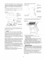
1. Assemble the protractor
head to the miter bar, as
shown in Figure 17. using a #10-32 x 1/2" long truss
head machine screw.
up and down a few
freely.
FIGURE
17
tA/LLLWARNING J Once the overhead guard has
"0
been assembled to the fence, DO NOT remove it for
any reason. Its removal can result in an unsafe operating condition that can result in possible bodily injury.
PUSH
BLOCK
ASSEMBLY
TO THE
ROUTER
._S
M_TER
32
-'qUSS
BA,q-
--USE
i
X ' 2-
LCNG
"EA3
MACMr-,E
-_'2
SCP_E¢,
'40LE
"'o o
,.j>
TABLE
FENCE
FIGURE 16
NOTE
] There
are two round
miter bar. Make sure the truss head
correct hole shown.
holes in the
screw
enters
the
2. Tighten truss head screw into the protractor
head
so that the wcrew head just touches the miter bar but
still provides a resistance
when the protractor
head
is rotated.
3. Assemble
1. Position the clamp plate relative to the push block,
as shown in Figure I6.
2. Align the rib and the V-shaped portion of the push
block with both the groove in the front of the fence
and the V-shaped portion of the fence.
3. Assemble the push block to the fence as shown in
Figure 16. The push block should move freely along the
full length of the fence when the guard is in the UP
position.
NOTE
the knob, the 3/16"
I.D. x 9/16"
.040" thick washer and the #10-24
head square neck bolt to the miter
head, as shown in Figure !8.
O.D. x
x 3/4" long round
bar and protractor
FIGURE 18
KNOB
3:16"1.D
X .040-
_
X 9:16"O
D _
THICK
WASHE=
_1_
:4
_%//--
=JNHEAD
40
X 3 4"
LONG
MACHINE
SCREW
_/,,_-,
_
,,-7%-
J
1. It is a good practice to frequently remove the dust
and chips that accumulate in use from the sliding
surfaces of the fence and the push block, and from
the groove in the fence.
2. The occasional application of a very light coating
of furniture wax to the SLIDING SURFACES ONLY,
of the push block, will improve the sliding action.
i
r4 40
HEX
Tg%gg¢o
SOUARE
4. Assemble the miter pointer to the miter bar using
the #4-40 x 3/4" long panhead machine screw and
the #4-40 hex machine screw nut. Make sure the
miter pointer POINTS in the right direction.
5. TIGHTEN screw and nut SECURELY
13
ROUTER
TO THE
ROUTER
[,_WARNING]
is NOT
TABLE
Always
PLUGGED
make
outlet
or the
NOTE
base
9-27504
plate from
the router.
and the base plate
the router
upside
down,
in a conveposition
it
the router base line up with the four corresponding
large countersunk
holes on top of the router table.
J Although
the fence assembly
Js
The holes will line up in ONE position only.
5. Insert four 1" long (M8 x 25 Metric) flat countersunk head machine screws through the holes in the
top of the table, and thread them into the threaded
holes in the router base. (These screws are not
included.)
6. TIGHTEN
the screws SECURELY
to the router.
shown installed on the router table in Figures 19, 20
and 21, REMOVING
the fence assembly
is recommended to facilitate the installation
and removal of
the router, For removing
the fence
Steps 13 through 15 on Page 12.
Craftsman
Routers
with
6" Diameter
Base Plates
holding
Model
against the bottom of the router table, as shown in
Figure 20.
4. Rotate the router until the four threaded
holes in
from the outlet.
l
the router
3. While
switch when the router is being installed on the
router table. If it is, UNPLUG
the power cord from
the outlet or the switch, and UNPLUG the switch
]
Router
1. Remove
2. Store the screws
nient location.
sure that the router
into an electrical
Craftsman
assembly,
Three-Hole
refer to
and
FIGURE
20
1. Remove the router base plate from the router.
2. Store the screws and the base plate in a convenient location.
3. While holding the router upside down. position it
against the bottom of the router table, as shown in
Figure 19. Rotate the router until the three threaded
holes in the router base line up with the three corresponding countersunk
holes on the top of the router
table.
5. When possible,
align the handles on the router
with the router table, as shown in Figure 19.
6. Insert three #10-32 x 5/8" long flat countersunk
head machine screws through the holes in the top of
the table, and thread them into the threaded holes in
the router base.
7. TIGHTEN
the screws SECURELY
to the router.
Craftsman Router Models 9-27505, 9-27506,
9-27510 and 9-27511
1. Remove the router base plate from the router.
2. Store the screws and the base plate in a convenient location.
3. While holding the router upside down, position it
against the bottom of the router table, as shown in
Figure 21 on the next page.
4. Rotate the router until the three threaded holes in
the router base line up with the three corresponding
large countersunk holes on top of the router table.
The holes will line up in ONE position only,
5. Insert three 5/16-18 x 1-1 4" tong flat countersunk
head machine screws through the holes in the top of
the table, as shown in Figure 21 on the next page,
and thread them into the threaded holes in the router
base. These screws are BLACK in color.
6. TIGHTEN the screws SECURELY to the router.
FIGURE 19
14
FIGURE
21
[ ,WARNING]
• DO NOT plug the power cord from the router
an electrical outlet AT THIS TIME.
• It WILL
because
into
be necessary
to use an extension
cord
of the short cord on the switch box. Refer
to the upcoming
MENTS,
under
section.
ELECTRICAL
USING THE SWITCH
REQUIREfor cord
specifications.
• Make sure that power cords from the router, accessories, the switch box. and the extension cord DO
NOT and CANNOT
COME IN CONTACT
with the
router or any moving parts of the router.
° Make sure that power cords from the router, accessories, the switch box, and the extension cord D©
NOT and CANNOT
Other Brands of Routers
It will be necessary for you to purchase a
Craftsman Professional Router Adapter Plate,
(9-25333), from your local Sears Retail Outlet or
through the Sears Catalogue.
Routers with a total overall height of 13 inches or
less and a base diameter of 7 inches or less can be
accommodated.
ROUTER
POWER
CORD
TO THE
INTERFERE
with any routing
operation or come in contact with the workpiece.
-. The power cord from the router is to be plugged
into the electrical
outlet only AFTER the setup for
your routing operation
has been completed.
• Refer to the upcoming
section. SWITCH BOX
OPERATION.
on Page 18.
• Refer to the upcoming
section. USING THE
ROUTER TABLE.
on Page 20_
SWITCH
,_.WARNING
• Make sure that the power cord from the switch box
IS NOT PLUGGED
into an electrical outlet while performing the following tasks. If it is plugged in.
UNPLUG it.
o MAKE SURE THAT ROUTER
SWITCH IS IN THE
OFF pOSITION.
1. Plug the router power cord into one of the outlets
on the switch box.
2. Form the excess power cord into a coil.
3. Wrap two pieces of friction tape or strong cord
around the coil at opposite sides of the coil.
4. Allow some slack so that the cord does not
become stretched when it is plugged into the switch
box.
5. If desired, at this time plug the power cord from an
accessory,
such as a web'dry vac or light, into the
other outlet.
15
FENCE
TO THE
ROUTER
TABLE
,_CAUTION
1. Refer to Steps 4 through 8 and Figure !4a on
Page 12.
Operating the router table without a wet/dry vac can
result in an excessive collection or build-up of sawdust and chips under the fence assembly and the
overhead guard. This can hinder the performance of
the router table and the fence assembly.
2. Adjust fence to desired location to obtain required
cut.
NOTE
RECOMMENDATION:
Regardless of whether a
wet/dry vac is being used, remove the sawdust and
wood chips from under the fence assembly and the
overhead guard as needed. This removal should be
done so that the performance of either is not hindered.
I
There are two scales, with 1/16" increments, molded
into the top of the router table to aid you in adjusting
the location of the fence.
4. TIGHTEN
the knobs when the fence
aligned at the desired location.
WET/DRY
assembly
is
RECOMMENDATION:
It is always a good practice to
keep the work area clean. As necessary, remove the
sawdust and wood chips from the top of the router
table, as well as any that has accumulated on the
floor around the router table.
VAC TO THE FENCE
The router table fence assembly has a port at the
back where a wet/dry vac hose can be connected.
The port will accommodate
nozzle.
To attach, push the nozzle
the fence in place.
a 2-1/2" diameter hose
into the port while
I
,_WARNING
When doing the above, keel_ the following in mind:
o The ROUTER and THE SWITCH must be turned
OFF.
holding
o The router bit must NOT be turning.
• The router power cord must be UNPLUGGED
from the switch.
• The power cord from the switch must be
UNPLUGGED from the extension cord.
16
TABLE
TOP INSERTS
TO THE
ROUTER
TABLE
I,_WARNINGJ
diameter
router
o 1-1/4" diameter, for use with router bits with diameters up to 1-1/8"
1. Select the table top insert that accommodates
router bit to be used.
• 1-7/8" diameter, for use with router bits with diameters up to 1-3/4"
2. Assemble the insert to the table top by pressing it
into the large hole in the top of the router table, as
shown in Figure 23.
• For router bits with diameters between 2" and 2-3/4"
the table top inserts are not used. See Figure 22.
bit that can be SAFELY
bit is the
This router table comes with three table top inserts in
the following hole sizes:
o 2-1/8" diameter, for use with router bits with diameters up to 2"
router
table.
A 2-3/4"
LARGEST
this router
used on
the
3. Press down equally over the tabs on the insert so
that the tabs snap into place.
4. To remove, insert a finger in the insert hole and
gently pull up until the tabs disengage the hole.
When not in use. store the inserts in a convenient
place.
FIGURE 22
[,_WARNING]
DO NOT attempt to remove insert
from the table top unless the router bit has been
removed from the router.
FIGURE
17
23
GENERAL
The Power Switch is designed to be used with most
Craftsman Router Tables and Routers. It provides the
convenience of an ON-OFF switch at the front of
the table, thus eliminating the need to reach underneath the table to turn the router ON and OFF.
This switch is intended for use on a circuit that has
an outlet, as illustrated in Figure A. The switch box
has a grounding plug, as illustrated in Figure A.
If a properly grounded outlet is not available, a temporary adapter, as illustrated in Figure B. may be
used to connect this plug to a two-hole receptacle.
as shown in Figure C.
FIGUREA
I
NOTE
and 9-27501) are a special case which is explained
in the section ROUTER AND SWITCH BOX
OPERATION.
B
FIGURE
C
Cover of
Grounded
The Power Switch also provides an optional simultaneous ON-OFF control of an additional accessory,
such as a light, vacuum, etc. The switch incorporates
an internal, resettable circuit breaker to provide protection in overload situations.
ELECTRICAL
FIGURE
I The electronic routers (9-1750
Adapter
_
Grounding
Grounding
Pin
Means
Cover
of
REQUIREMENTS
The temporary adapter should be used only until a
properly grounded outlet can be installed by a qualified electrician. The green colored rigid ear or lug
extending from the adapter must be connected to a
permanent ground, such as a properly grounded
outlet box.
In the event of a malfunction or breakdown, grounding provides the path of least resistance for electric
current in order to reduce the risk of electric shock.
This switch box is equipped with an electric cord that
has an equipment grounding connector and a
grounding plug. The plug must be plugged into a
matching outlet that is properly installed and grounded in accordance with all local codes and ordinances.
[,_WARNING
DO NOT permit fingers to touch
terminals of the plug when installing or removing
from the outlet. If not properly grounded, this power
tool can present the POTENTIAL HAZARD OF
DO NOT modify the plug provided if it will not fit the
outlet. Have the proper outlet installed by a qualified
electrician.
ELECTRICAL SHOCK, which can possibly result in
DEATH, particularly when used in a damp location,
in proximity to plumbing or out of doors. If an electrical shock occurs, there is always the potential of a
secondary hazard, such as your hands contacting
the router bit.
Improper connection of the equipment grounding conductor can result in risk of an electric shock. The conductor with insulation that has a green outer surface,
with or without yellow stripes, is the equipment
grounding conductor. If repair or replacement of the
electric cord or plug is necessary, DO NOT connect
the equipment grounding conductor to a live terminal.
['_WARNINGI
Use the switch box ONLY when
Check with a qualified electrician or service person if
the grounding instructions are not completely understood, or if there is doubt as to whether the switch
box is properly grounded.
properly assembled to the router table. Use only with
a router which has also been properly installed on a
properly assembled router table.
Use only 14 gauge, or larger, three-wire extension
cords that have three-prong grounding plugs and
three-hole receptacles that accept the tool's plug.
SWITCH BOX OPERATION
This section
Repair or replace a damaged or worn cord immediately.
The electrical outlet on the back of the switch box
explains
the operation
and features
of
the switch box prior to plugging the power cord into
an electrical outlet. The intent is to familiarize
the
will accept either a two-prong plug from a DOUBLE
INSULATED router or accessory, or a three-prong
grounding type plug.
user with the switch box operation
turning ON the router.
18
without
actually
Theswitchboxincorporates
twopositivesafetyfeaturesto preventinadvertent
switchingONof the
routerandthe unauthorized,
andpossiblyhazardous,
useby others.Inadvertent
switchingONof therouter
is preventedby theclearplasticswitchcover.The
covermustberaisedandtheswitchmanuallytoggledto the ONpositionto startthe router.Also,the
safetykeycanbe removedto disabletheswitchbox
by "locking"theswitchin the OFFposition,thuspreventingunauthorized
andpossiblehazardous
use.
Inan emergency,
theswitchcanbeturnedOFFby
slappingor strikingtheswitchcoverwiththehand.
Tooperatethe switchbox.proceedasfollows:
l
NOTE
Because the switch also func-
ROUTER
This
with
The
gled
AND
SWITCH
BOX
OPERATION
section explains operation of the switch box
the power cord plugged into an electrical outlet.
router will turn ON when the switch is togto the ON (or RESET) position.
1. Position the ON-OFF switch on the router in the
ON position. On certain routers this will require the
use of the Switch Trigger and "LOCK-ON" button.
(Consult router owner's manual.) Make sure the
switch box lever is in the OFF position when
doing this.
2. To turn the router ON, slide finger under the
switch cover and toggle the switch to the ON position. as described in the previous section.
3. To turn the router OFF. press the switch cover, as
described in the previous section.
tions as a circuit breaker, the ON position is labeled
RESET on the switch. For clarity this instruction uses
ON in place of RESET.
SPECIAL
1. Insert the safety key into switch box. See Figure 24.
NOS.
NOTE
9-1750
AND
TO OWNER'S
9-27501
OF MODELS
ROUTERS
FIGURE 24
Because these routers come with a special "LOCKON feature that will not permit it to be turned ON by
the switch box (but allow router to be turned OFF by
the switch) the following
method of operation
is to
be used:
1. Toggle the switch box switch, as described
in the
previous section. The router should NOT start even
though the trigger lock is in the "LOCK-ON"
position.
(Consult router owner's manual.)
2. To start the router, depress the trigger and
engage the LOCK-ON
button located on the side of
the handle. THE ROUTER SHOULD
START IMMEDIATELY.
If the router switch is already in the "LOCK-ON" position (The "soft" and "1/4 inch" indicator lights will be
flashing - consult router owner's manual), unlock the
trigger. Depress the trigger, and THE ROUTER
WILL START IMMEDIATELY. Engage the "LOCKON" button on the side of the handle.
2. To turn router ON, insert finger under switch cover
and toggle switch to ON position.
3. To turn router to OFF, press switch cover.
NEVER leave router UNATTENDED
come to A COMPLETE STOP.
until it has
3, To turn the router OFF, press the switch box
switch cover.
4. To lock switch to OFF position, remove key from
switch-box.
4. To restart the router,
perform Step 1 through
With the key removed from the switch box, the
switch cannot be toggled to the ON position.
I
I,_WARNINGJ
Before proceeding any further,
make sure the switch on the router is in the OFF
NOTE
it will always
Step 2.
be necessary
to
I
t In the event of an overload situa-
tion, the internal switch box circuit breaker may trip
and toggle the switch to the OFF position. This will
interrupt the power to the router and/or vacuum. If
this occurs please do the following:
position and the switch lever is in the OFF position.
The switch box power cord can now be plugged into
a wall outlet.
1. Unplug the switch box cord from the electrical outlet.
2. Clear the workpiece from the router table.
19
3. Correct the cause of the overload situation (i.e.
the removal of too much stock or use of too high a
feed rate).
4. Plug the switch box power cord into the electrical
outlet.
5. Restart the router as described in the section
ROUTER AND SWITCH BOX OPERATION on
Page t 9.
[,_WARNING]
For your own SAFETY and the
SAFETY OF OTHERS, do the following when the
router table is not in use:
1. Toggle the switch lever to the OFF position and
remove the key.
2. Turn the router OFF.
3. Unplug the switch box power cord from the electrical outlet.
4. Remove the router bit from the router.
5. Make sure the router collet assembly is below the
top of the router table.
6. Store the switch box key in a safe location where
it is not available to children or other unauthorized
persons.
['_WARNINGI
In the event of a power failure.
blown fuse, or router "stalling out while routing, push
the switch cover to toggle the switch to the OFF
position and remove the key from the switch box
until the source of the problem has been corrected.
In addition, UNPLUG the switch box from the electrical outlet.
USING THE ROUTER TABLE
[,_WARNING
1 BEFORE each and every use,
make sure that the floor stand is STABLE on the
floor and DOES NOT rock back and forth. If it does.
level the floor stand as described in a prior section.
The adjustable fence on your table is provided as a
guide against which the workpiece should be held for
accuracy in routing. FREE HAND ROUTING (not
holding work against the fence) is HAZARDOUS and
should be STRICTLY AVOIDED without piloted
router bits.
2O
ROUTING
PUSH
USING
THE
FENCE
WITHOUT
5. Loosen the fence clamping knob on the
adjustable jointing fence and move it out, flush
against the finished edge of scrap wood. Retighten
the knob. See Figure 26.
6. Repeat the test cut on the scrap wood with overhead guard DOWN.
7. The router table is now ready for use.
THE
BLOCK
Full Edge Cutting:
For maximum strength and accuracy, boards to be
joined together should be smooth and true. The edges
should be true to the workpiece surface. You can true
the edges on your router table using a straight bit.
1. Check to see if face of adjustable jointing fence is
flush with the face of the router table fence. If not,
loosen adjustable fence clamping knob on jointing
fence and adjust. Tighten the fence clamping knob
on the adjustable fence.
I
NOTE
I
J For best results when jointing,
Edge Cutting With Non-Piloted
Router Bits:
1. Position the adjustable jointing fence so that its face
is flush with the face of the table fence. Tighten
adjustable fence clamping knob on jointing fence. See
Figure 27.
2. Adjust depth of cut (material you want to remove)
and router bit height, as described previously in
ADJUSTING DEPTH AND HEIGHT OF THE CUT,
Steps 1 - 4 on Page 20. Tighten both fence clamping
knobs to lock fence on table. Tightly secure the
router. (Make sure router is UNPLUGGED when
making adjustments.)
3. LOWER THE OVERHEAD GUARD to the OPERATING POSITION. Overhead Guard shown raised for
]
J The adjustable jointing fence pro-
2. Adjust depth of cut (the material you want to
remove) and router bit height as described in Steps
1 - 4. ADJUSTING DEPTH AND HEIGHT OF THE
CUT on Page 20. Tightly secure the fence and the
router as described before. (Make sure router is
UNPLUGGED when making adjustments.)
reasons of clarity.
4. Test cut a piece of scrap wood to make sure
adjustments are satisfactory.
3. LOWER THE OVERHEAD GUARD to the operating position. (Overhead guard shown raised for reasons of clarity.)
4. Check your adjustments by turning the router ON,
using the switch, and feeding a piece of scrap wood
a few inches beyond router bit. Then stop and turn
router OFF, using the switch.
NOTE
]
take very shallow cuts, !/32" or less.
vides a continuous support for the workpiece as it is
fed beyond the router bit. The adjustable jointing
fence compensates for the gap created after the
removal of material by the router bit.
I
NOTE
I
NOTE
]
J Feed work AGAINST the rotation
of the cutter (in the direction shown by the arrow in
Figure 27).
5. The router table is now ready for use.
I
I Feed work AGAINST the rotation
FIGURE 27
of the cutter (in the direction shown by arrow in
Figure 26).
FIGURE 26
Overhead
Overhead
Guard shown
raised for reasons
of clarity.
21
Guard
shown
raised
for reasons
of clarity.
Edge Cutting
With Piloted
Router Bits:
1. Position the fence in the same manner
FIGURE
29, VIEW
FROM
LEFT
SIDE
OF
ROUTER
as with
non-piloted
bits.
2. Move the fence back only enough to permit the
pilot to control the cutting depth• Positioning the fence
as close to the pilot as possible will serve as a backup and will help to prevent chances of an accident
and possible personal injury. See Figure 28.
3. LOWER THE OVERHEAD
GUARD to the OPERATING POSITION.
Overhead
guard shown raised
reasons of clarity.
4. Test cut a piece of scrap wood to make sure
adjustments
are satisfactory.
NOTE
for
I
J Feed work AGAINST the rotation
NOTE
of the cutter (in the direction shown by the arrow in
Figure 28).
5. The router table is now ready for use.
I Test cut a piece of scrap wood
before making your finish cut. Feed workpiece
in the
direction
of arrow. (Refer to Figure 30.)
FIGURE
FIGURE 30
Overhead
28
Guard
shown
raised
for
reasons
of clarity.
I
Grooving, Fluting, And Veining:
Always UNPLUG the router before making any
settings, adjustments, or changing bits.
NOTE
I
I When
routing
deep
cuts (con-
trolled by router bit) in a workpiece,
remove a small
amount of material to prevent your router from overloading. Repeat operation
with several gradually
deeper passes until the desired depth is achieved.
When routing, always FEED AGAINST the rotation
of the cutter. Feed workpiece in the direction of
arrow, as in Figure 28.
END CUTTING USING THE FENCE WITH
THE PUSH BLOCK
For maximum accuracy, one edge of your workpiece
(edge sliding against the fence) must be true and
straight. Set up your fence as follows:
1. Position the fence behind the router bit for the
desired cutting depth (the distance of the cut from
the edge of the workpiece, as shown in Figure 29).
Make sure the overhead guard is in place as shown.
I,_WARNINGJ
End cutting
overhead
guard rotated
cover the bit. Therefore,
is performed
with the
back so that it does not
EXTREME
CARE must
be
2. Securely TIGHTEN both knobs.
taken when end cutting so that your fingers, hands,
or any other part of your body, DO NOT contact the
bit, which can resulT, in serious bodily injury.
3. Make the cut by sliding the straight edge of workpiece
against the fence, as shown in Figure 30 (For each
successive cut, the fence would need to be readjusted.)
When routing on ends of workpiece
for making
tenons, sliding dovetails
and tongue and groove
joints, the workpiece
must be made smooth with
22
both the edges and the ends made
other and the surfaces.
A__,surfaces
or at 90:, with each othe _
NOTE
assembly
than 4".
The push block
will not accommodate
6. Slide workpiece
close to the bit and adjust the
fence and the router, as described
before, so that
true to each
must be square,
and clamp
workpieces
the outer most cutting edge of bit is aligned with Line
"A" and top cutting edge of bit is aligned with Line
"B." See Figure 31. Tightly secure the fence and the
router, as described
before in ADJUSTING
DEPTH
plate
wider
AND HEIGHT OF CUT on Page 20.
7. Slide push block, and therefore workpiece,
back to
the position,
as shown in Figure 32.
When routing, always FEED AGAINST
the rotation
of the cutter. Feed workpiece
in the direction shown
by the arrow in Figure 32.
Cutting
Tenons:
1. Make certain that adjustable
jointing fence is
locked in position with its face flush with that of the
router table fence.
2, Mount push block assembly
on the router table
fence, as shown in Figure 16 (on Page 13) in the
section PUSH BLOCK
ASSEMBLY
TO THE
ROUTER TABLE
FENCE.
3. Install
hole.
proper
FIGURE
32
table top _nsert into the table top
4. Mark Lines A and "B on the edge of the workpiece closest to the end :o be cut. Line "A" is for
FULL DEPTH OF CUT (total amount of material you
want to remove) and Line "B '_ is for FULL DESIRED
HEIGHT OF TENON.
See Figure 31.
5. Position workpiece
be:,veen c:amp plate and
push block so that its sloe is he!d flush against face
of the fence, the end to :e cut _s resting on the
edge of the router table _op inset.: hole, and the
8. Turn router ON. using the switch. While holding
push block and guiding workpiece against fence with
BOTH HANDS AND FINGERS a SAFE distance
edge marked with Lines 'A and B is facing router
bit. Clamp workpiece
in tb,is position by snugly tightening the wing nut on clamp rod, while making sure
that clamp plate stays oriented
on workpiece,
as
shown in Figure 31. Make sure router is
UNPLUGGED
when positioning
and clamping
workpiece and making adjustments.
from rotating bit, feed the workpiece across the bit to
make a FULL DEPTH OF CUT IN ONE PASS. as
shown in Figure 32. (DO NOT stop feeding the workpiece until it has COMPLETELY PASSED the rotating bit.)
FIGURE 31
;NC =-:
C_AMP
'¢_Oq_tP_EC, E S_DE -
"
AGA;NST
OF
FACE
BOUTEN
FACE
O F
PLATE-
ESE-
--
=_'SH
_
I
BLOCK
/--WING
._._.,., __
..>__
,,,_FE',,CE
B!T
OF _DL;-E
=
T'_B _E PEXCE
O _ =CuTEN
B"
EDGE
P4SE
DERECT;ON
'C = -_,BLE
_,-
TOP
_O-E
____
4
MAXIMUM
WIDTH
...............
NOTE
]
J Tighten
wing
nut just enough
1
I Clamp and test cut a piece of
scrap wood to check your adjustments before making your finished cut.
9. Turn router OFF, using the switch. Unclamp workpiece, and slide push block back to the other side of
the bit.
10. Position and clamp the opposite side of workpiece in the same manner as described in Step 5.
(Make sure the wing nut is just tight enough to clamp
workpiece in position and end to be cut is resting on
the router table top.) Repeat Steps 7, 8, and 9.
(Refer to Figure 33 on Page 24.)
11. To cut ends of tenon, position and clamp work-
NUT
FENCE\
NOTE
piece in the same manner as in Step 5 above,
except edge of workpiece
should be held flush
against face of fence and end to be cut should be
resting on the top of router table. See Figure 34 on
Page 24. Repeat Steps 7. 8, 9, and 10.
to
clamp workpiece
in position. OVER TIGHTENING
wing nut could cause binding in the sliding motion of
push block, which in turn may result in variations
and/or steps in the finished tenon surface when cut,
See Figure 35 on Page 2_.
23
I
NOTE
t Whencuttingtenons,always
clampworkpiecewithendto becutrestingonthe
routertabletop.Thiswillminimizestepsin finished
tenonsurfacedueto variationsin thetabletopflatness.(Referto Figure35.)
WITHOUT
AND
PUSH
THE
With
Piloted
Without
USING
THE
FENCE
BLOCK
Router
Bits:
the Starting
Pin:
[,_WARNING]Routing
I
I Always CUT FULL DEPTH on al!
four sides of tenon in one pass across the bit.
NOTE
FIGURE
ROUTING
without
the unitized
fence
assembly
and overhead
guard could cause accidents and possible
personal
injury. EXTREME
CARE must be taken for this routing operation.
33
Always
UNPLUG
ting adjustments
Always FEED
of the cutter.
the router
before
or changing
bits.
WORKPIECE
making
AGAINST
any set-
the rotation
Only PILOTED router bits are to be used.
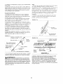
Many routing applications (as shown in Figures 36
and 37) will require the fence to be removed from
the table.
Figure 36 is an example
of OUTSIDE
ROUTING.
• The position of the workpiece
on the router table
relative to the router bit must be as shown.
• The direction of feed for the workpiece
through the
router bit must be as shown by the direction arrow
and AGAINST
the rotation of the router bit.
FIGURE 34
FIGURE 36
FIGURE
Figure 37 is an example of INSIDE ROUTING.
,, The position of the workpiece on the router table
relative to the router bit must be as shown.
35
,, The direction of feed for the workpiece through the
router bit must be as shown by the direction arrow
and AGAINST the rotation of the router bit.
STEPS
TENON
IN FINISHED
SURFACE
24
FIGURE
37
FIGURE
39
.
FREE
THE
ROUTING
PUSH
WITHOUT
USING
THE
FENCE
4. Gradually
and slowly move the workpiece toward
the router bit untii the workpiece
contacts the pilot on
the bit and cutting begins, as shown in Figure 39.
The direction of feed is AGAINST
the rotation of the
AND
BLOCK
Irregularly
Shaped
Workpieces:
With Piloted
Router Bits:
Without
the Starting
router
Pin:
For routing irregularly sha_ed workpieces,
a starting
pin is provided. The STARTING
PIN is used for
'free-routing"with
PILOTED
router
NOT USED for any o,:her c_eration
manual.
1. Remove
table.
the router
table
fence
bits only Itis
described
in this
from
maintaining
contact with the starting pin, until it completely clears the bit.
9. Turn the router OFF, using the switch.
hole in
hole.
ROUTING
I
NOTE
38
Storage
Hole
Starting
USING
THE
MITER
GAUGE
AND
THE
FENCE
End Cutting:
Your miter gauge will serve as a handy aid when
extra support is needed for routing small workpieces
or the ends of long workpieces. See Figure 40.
Guard shown raised for reasons of clarity.
J When not in use. the starting pin
can be stored conveniently
in the storage hole at the
back of the router table top, shown in Figure 38.
FIGURE
by the arrow.
7. Gradually
move the workpiece
toward the starting
pin until the workpiece
contacts
it.
8. Back the workpiece
away from the router bit. while
the router
2. Thread the starting pin _nto the threaded
the router table top, to the right of the large
(Refer to Figure 38.)
bit, as shown
5. Move the workpiece
away from the starting pin.
6. Feed the workpiece
through the bit. while pressing
it against the pilot on the bit. until the cut has been
completed
around the workpiece.
Pin
FIGURE 40
3. Position the workpiece
on the router able top so
that it contacts the starting pin, BUT NOT THE
ROUTER
BIT, as shown in Figure 38.
Overhead
25
guard
shown
raised
for
reasons
of clarity.
I
NOTE
I For ALL routing operations
,_WARNING]
requiring use of miter gauge along with the fence,
be sure to align fence with miter bar slot before
making any cuts. Refer to the section, FENCE, on
Page 11.
o The GUARD MUST BE DOWN in the OPERATING
POSITION when using the miter gauge.
o Always HOLD the workpiece FIRMLY and
SECURELY AGAINST the miter gauge, the router
table and the fence when making this cut.
Miters can be cut by loosening the protractor head
knob, turning the protractor head up to 60 ° in
either direction and retightening the protractor
head knob.
• Make sure that NEITHER YOUR FINGERS,
HANDS, NOR ANY OTHER PART OF YOUR BODY
is in line with the router bit when using the miter
gauge, or serious bodily injury can occur.
26
PARTS
LIST
FOR
CRAFTSMAN
PROFESSIONAL
ROUTING
MODEL NO. 171.254841
CENTER
g
/ i
KEYI
PART
NO.
Ir
1
I 29LCN-981
2
29LCN-986
I DESCRIPTION
I Router Table Assembly_
Professional
Router
Router
Consists
_ 4
3
29LCN-1120
Startinc
4
29LCN-996-1
Table
Toplnsert
5 16" Pilot_ .......
(O 1-1/4" 1
i ..!
5
29LCN-996-2',
Table
T_j__lnsert
(O 1-7/8")
L1
6
29LCN-996-31
Table
_lnsert
(O 2-1/8")
I
7
29LCN-990
!Side
8
-9
29LCN-988
2_9
I Extension
[ __eft
I
I Fence
Assembly
10
29LCN-994
L Router
Table
12
_CN_-997!
Fence
Extension
! DESCRIPTION
_-10_[
L_ve_h-ng_Foot ....
S,_itch Assembly
!
30AI29LCN-1018!
Switch
31_r29A-1i13
7 _'10-32
33
,29A-242-16i
__29A-_3-7
1
......
18
29L-652
Plate
'
-39
-40
r1
_45_-323-
I Fence Warning Label
j (Assembled
by Manufacturer)
--T1
[
_-
....
29LCN-966
_onsists
! Miter Bar
of: I
I 1
41
129A'327"5_
129L-469-21
]29L.
469-22
I29LD'841-2
45
h_ _n--_o_t_n_
i
11/32"
Thick
Thick
#4-40
4
1
j
1
of:
i
.....
,80
of:I _
t 1
27
47
129A-310-0
Nut
1
Nut
,-_-x ,040Pushnut
I 1
I2
....
t
Washer
.......
I.D. x 11,,16" O,D.
i
x 1/16"
Washer
Spring Lock Washer
x 3,4" Lg. P'Hd. Mach.
x 1-1/4'
_
Hd,
Screw
x 1/2" Lg.-_-russ Hd,_Ma
Screw w/Phi!li_s
Recess
wi Philli s Recess
1/4-20
x 1" Lg. Hex Cap
Screws
x 3'4"
Lg. Round-He_--
S_uare
Neck
Bolt
1
L
!
[_I -_'
Lg. Flat C'sunk
#10-24
•
!
Math.
#10-32 x 5/8" Lg. Flat C'sunk
Screw w/ Phillips Recess
4 #10-32
29-A_-46_20-'
Screw
#10-32 x 7'8" Lg. P'Hd,
I Screww/PhillipsRecess
5,,16'18
-q
2__-1Mach.
_7 2_LCN-__o_
,
o o84 .14
2
_- 29LCN-967
_---4_
_'7i_
3,'16' I.D, x 9/16"
1 '4"Washer
€_p
Thick
20
___co_sists
Consist
Hex Machine
5,'16-18
-1-
Overhead
Guar_
P_ot
Pin---_
I Clamp
(Re_oair Part Op!y_ ......
i
_[
i
!
_38 2_:_-_
T_ __,
! _4
H_x'_KKEPS'_u-t
!/4-28
--1_
Kev
_
1
of:
Fence
Bracket
r Bagged - Fasteners
2 3345__252-16
-2-_
D-321
Side)
iQTY
Leveling
2
__
Consists
PART NO.
28_29LCN-1118!
L1 __1171
Table
Table LeG
Pin(O
KEY I
iQTY
of___
[ 14-20Xsquare
Neckl-3_:Lg:Bolt
R0und-Heea-d
I
3
Hd. I
3
h_
78
.L_
1
1-
2-
TABLE
ASSEMBLY
"T"
f/_°
,/
_
/
/,
J
z
,
J J
j//
.: f/
J_c
1
./
_J
MISCELLANEOUS
PARTS
FENCE
ASSEMBLY
t /
/
/i
/
/
!
28
\\
MITER
GAUGE
SWITCH
ASSEMBLY
_L
\,
iae_
z
,F
i
!
LEVELING
BRACKET
_CYs" ../
FLOOR
STAND
\\
29
ASSEMBLY
,
GUfA DE SEGURIDAD
Este manual
contiene
informaci6n
muy importante
que usted debe
conocer y comprender.
Esta informacion esta. relacionada
con la
MAS CON LOS EQUIPOS.
INFORMACI6N
SEGURIDAD.
causarle
heridas
1. Conozca
fisicas
INDISPENSABLE
UN RIESGO
HERIDAS
DE
QUE LE
INFORMACION
DANOS
PARA
PREVENIR
A LOS EQUIPOS.
MUY GRAVES
O LA MUERTE.
Para
ayudarle a distinguir que clase de
informacion contiene, usamos los
simbolos a la derecha. Por favor,
lea el manual con atenci6n especial a esas secciones.
I'_,ADVERTENClAI
APRECAUC,0NI
PELIGROJ
CAUSAR.A
protecci6n de su SEGURIDAD
y
la PREVENClON
DE PROBLE-
- DEFINICIONES
No seguir
NOTA
,_ADVERTENCIA
INFORMAClON
SEGURIDAD.
PODRiA
GRAVES
IMPORTANTE
UN RIESGO
CAUSARLE
DE
QUE
HERIDAS
INFORMACION
DEBE
MUY
TENER
QUE USTED
ESPECIALMENTE
EN CUENTA.
O LA MUERTE.
todas las instrucciones
de manejo y seguridad
referidas
a este producto
puede
graves.
su herramienta
electrica
8. Tenga su taller a prueba de niflos
Cierrelo con candados, cerraduras o retire las tlaves de
puesta en marcha.
9. No fuerce las herramientas
Lea cuidadosamente
el manual del propietario.
Conozca sus aplicaciones
y limitaciones, asi como los
peligros potenciales
particulares
de esta herramienta.
2. Conecte a tierra todas las herramientas
(excepto
las que tengan doble aislamiento
electrico)
Si la herramienta
tiene un cable homologado
de tres
hilos y un enchufe de tres clavijas con toma de tierra,
se deber_, enchufar a una base de enchufe con tres
HarA su trabajo mejor y mAs seguro
la que fueron disefiadas.
10. Use la herramienta
correcta
a la velocidad
No obligue a la herramienta
o accesorio
trabajo para el que no fue dise_ado.
11 .Vistase adecuadamente
entradas. Si se usa un adaptador para utilizar una base
con dos entradas, el cable adaptador se debera,
conectar a tierra (habitualmente
al tornitlo de fijaci6n de
la tapa del enchufe). Nunca quite la tercera clavija. No
conecte nunca el cable verde de tierra a un polo activo.
3. Mantenga
las tapas en su lugar
Mantengalas
en disposicion
de trabajo, alineadas y
ajustadas correctamente.
4. Retire las Ilaves de ajuste y otras herramientas
AcostQmbrese
a cerciorarse
de que todas las Ilaves de
ajuste y otras herramientas
se han retirado antes de
poner en marcha la maquina.
5. Mantenga
limpia el Area de trabajo
En las zonas o bancos de trabajo desordenados
son
ma.s probables los accidentes.
El suelo no debe estar
resbaladizo
por el uso de cera o la presencia de serrin.
6. Evite los entornos
peligrosos
No use las herramientas
electricas en lugares humedos
o mojados, ni las use bajo la Iluvia. Trabaje en lugares
bien iluminados. Trabaje con espacio suficiente.
7. Mantenga
alejados
a los niflos
Todos los acompa_antes
deben permanecer
a una
distancia prudente del Area de trabajo.
para
a hacer un
No Ileve ropas demasiado amplias, guantes, corbatas,
joyas (anillos o relojes de pulsera) que puedan set
atrapados por las partes moviles de la maquina. Es
recomendable
usar calzado no deslizante. Pongase
cobertores de pelo para recoger el pelo largo. Si Ileva
manga larga, remanguese
por encima del codo.
12. Use gafas de seguridad (Protecci6n
para la
cabeza) Pongase siempre gafas de seguridad (deben
cumplir con la norma ANSI Standard Z87.1). Utilice
tambien una mascarilla si la operacion de corte
des-prende
polvo, y protectores de oidos (tapones u
orejeras) si trabaja por un periodo de tiempo
prolongado.
13. Sujete bien la pieza de trabajo
Use presillas o mordazas para sostener bien las
piezas cuando este trabajando.
Es mb.s seguro que
sostenerlas
con las manos y deja estas libres para
manejar la maquina.
14. No pierda el equilibrio
Mantenga los pies y el cuerpo en posicion correcta
todo el tiempo.
30
15. Cuide
(
ff
del mantenimiento
de las herramientas
21. Direccion
en la introduccion
de piezas
Introduzca las piezas unicamente
en contra de la
direccion de rotacion de la fresa, sierra o herramienta
de code.
22. Nunca deje la maquina
funcionando
sola
ApAguela. No abandone la maquina hasta que no este
completamente
parada.
23. Mantenga
las manos alejadas de la zona de corte
24. Guarde las herramientas
cuando no las este
usando
Cuando no esten siendo utilizadas, las herramientas
Mantengalas
afiladas y limpias para obtener un
rendimiento
mejor y mas seguro. Siga cuidadosamente
las instrucciones
para engrasarfas
y cambiar los
accesorlos.
16. Desconecte
las maquinas
Antes de su mantenimiento,
cuando cambie accesonos
como cuchillas, fresas, piezas, etc.
17. Evite los arranques
accidentales
Aseg0rese de que la caja de conexi0n estA en OFF
antes de enchufar.
18. Utilice los accesorios
recomendados
Consulte el manual del propietario
para conocer los
accesorios recomendados
y siga las instrucciones.
El
uso de accesorios inadecuados
puede ser peligroso.
19. Nunca se apoye sobre la maquina
Se podria producir heridas graves si la herramienta
se
vue!ca o si toca accidentalmente
la parte cortante. No
coloque materiales u objetos por encima o cerca de la
maquina de modo que sea necesario inclinarse sobre
ella para alcanzarlos.
20. Compruebe
las piezas estropeadas
Antes de seguir utilizando la maquina, cualquier tapa o
guarda dar_ada deberia ser comprobada
para
asegurarse de que funcionara, correctamente
y
cumplir__ con la funcion asignada. Compruebe
la
alineacion y fijeza de las pieZas moviles, la rctura de
piezas, el montaje y cualquier otra circunstancia
que
pueda afectar a la operacion. Una tapa, guarda o
cualquier pieza deteriorada
por el tiempo, debe ser
reparada o reemplazada.
se deben guardar en un lugar seco y alto o
cerrado -lejos
del alcance de los niSos.
25. No fuerce el cable
Mantenga el cable alejado
bordes cortantes.
de calor, aceite y
26. Alargaderas
para el exterior
Cuando utilice la maquina al aire libre, utilice
alargaderas
apropiadas para ese uso, que esten
etiquetadas
para ello.
27. Nunca use la herramienta
en atmosferas
explosivas
Las chispas del motor, que son normates, podrian
infiamar vapores, I[quidos inflamables o productos
combustibles.
28. Drogas, alcohol,
medicamentos
No utilice la mAquina bajo la infiuencia de drogas,
alcohol o cualquier medicaci6n.
Lea y comprenda
este libro de instrucciones
en su totalidad ANTES de usar el producto.
1. Use siempre proteccion para los ojos que cumpla la
Norma ANSI Z87.1.
2. Los niveles de ruido vanan ampliamente seg0n el lugar.
Para evitar posibles dar_os al oido. use tapones para oidos
o tapaorejas cuando vaya a usar la mesa fresadora
durante largos periodos de tiempo.
3. Para operaciones que produzcan polvo, use una
mascara antipolvo junto con anteojos de seguridad.
4. Siga las instrucciones indicadas en el manual de
usuario de su fresadora.
I1
de fuentes
9. Este producto esta dise_ado para cortar piezas planas
de trabajo. No corte ni intente cortar piezas de trabajo que
no sean planas.
10. Este producto debe usarse 0nicamente para cortar
piezas de madera. No use esta fresadora para cortar
metal u otros materiales que no se sean de madera.
11. Cuando se fresen piezas grandes de trabajo se
recomienda enfaticamente usar soportes auxiliares para
hacer avanzar la pieza hacia la fresadora y hacerla salir
de ella. Si no se usan esos soportes auxiliares la mesa
fresadora podrfa volcarse.
12. Mantenga las manos lejos de las brocas fresadoras y
del Area de trabajo.
13. Elabore y use un trozo de madera de empuje para
mover las piezas peque_as de trabajo a Io largo del a.rea
de corte.
14. Limpie la fresadora despues de usarla. Se recomienda
usar un equipo de aspiracion h0meda o seca.
15. Asegurese de que la superficie de trabajo de la mesa
fresadora este limpia y libre de polvo, astillas y partfculas
extra,as que puedan interferir con el corte que usted va a
realizar. Se recomienda usar un equipo de aspiracion de
materiales h0medos y secos.
16. La guia que viene con ta mesa fresadora tiene un
colector de polvo (si esta disponibte en un modelo
cerrado) al cual se le puede conectar una aspiradora para
materiales secos o h0medos. AI usar la guia se
recomienda el uso de una aspiradora para materiales
h0medos o secos.
I
I'&ADVERTENClAI
5
Las vibraciones, causadas por la
fresadora durante su uso, pueden afiojar los sujetadores.
Antes de usar la fresadora y periodicamente
durante su
uso, revise todos los sujetadores para asegurarse de que
todos esten bien apretados y seguros.
6. No use este producto hasta que haya comptetado todos
los pasos necesarios para armarlo e instalarlo. AsegOrese
de haber leido y comprendido todas las instrucciones de
seguridad y operacion indicadas en este manual yen el
manual del usuario de la fresadora.
7. Asegurese de que la broca de la fresadora este en
posicion correcta y totalmente sujeta en la fresadora antes
de efectuar cualquier corte.
8. No use la mesa fresadora como un banco o supefficie
de trabajo. Si la usa de ese modo podria daharla y hacer
que sea peligroso utilizarla. Se debe usar un banco de
trabajo con esta finalidad.
31
17.Compruebe
etfuncionamiento
delresguardo
antesde 24. Algunas fresadoras, cuando se las coloca en posici0n
cadauso.Eliminetodoelpolvo,astillasy demas
_nvertida. como, por ejemplo, en una mesa fresadora, se
particulas
extraSas
quepuedan
afectarsufuncionamiento.saldran o caeran de la base de la fresadora cuando se
Ajustelaalturadelresguardo,
detalmanera
queno
afioja la abrazadera de base para ajustar la altura o la
interfiera
nitoquelasbrocasfresadoras
o lapiezadetra- profundidad de code. Por consiguiente.
esextremadamente
importante apoyat la fresadora desde
bajo,o laquetencjama.s
alturadelasdos.
/A
I
abajo cuando se efectuen estos ajustes o siempre que se
afloje la abrazadera.
25. Mire siempre debajo de la mesa fresadora al
interruptor de la fresadora cuando vaya a apagar o
encender la fresadora. Toque solamente el interruptor
cuando vaya a encender o apagar la fresadora. Nunca
ponga su mano debajo de la mesa fresadora por ninguna
razon cuando la fresadora este funcionando, salvo para
apa_arla,
t ADVERTENOIAJsus
de0os
debajo del resguardo cuando la fresadora este enchufada
en una toma de corriente electrica o cuando la broca
fresadora este girando.
19. Use siempre ta gufa para encaminar el
desplazamiento
de la pieza de trabajo.
NO TRABAJE A MAN© ALZADA a menos que se esten
usando brocas fresadoras tipo pi!oto.
20. Use siempre brocas fresadoras tipo piloto para los
trabajos de fresado a mano alzada de piezas de trabajo
que tengan forma irregular.
21.Haga avanzar siempre la pieza de trabajo CONTRA la
rotacion de la cuchilla o la broca.
22. Las brocas fresadoras son extremadamente
afiladas;
actOe con suma cautela al manejarlas y usarlas.
23. AsegQrese de que las brocas fresadoras que se esten
usando esten bien afiladas o se les haya vuelto a afilar
apropiadamente.
Esto permitira fresar con rapidez,
eficiencia y SEGURIDAD.
26. IA!,_I_ADVERTENCIA
Antes de efectuar cualquier
corte, asegurese de que la fresadora este apagada, la
broca fresadora no este girando y el cordon de
alimentaci6n electrica este desconectado de la toma de
corriente. Despues asegurese completamente de que el
resguardo no tropieza con la broca de la fresadora y la
pieza de trabajo. Se recomienda enfa.ticamente realizar un
pase de prueba con la fresadora apagada y la broca
fresadora sin girar.
/A
i
27. [,&ADVERTENClAI
Nunca deje la mesa de la
fresadora funcionando sola sin su atencion. Apague la
fresadora antes de dejar la mesa fresadora por cualquier
razon.
Su mesa Craftsman viene con los siguientes accesorios:
- Una guia unitaria Qnica de 4 pulgadas de altura con
orientadores de guionan movimiento paralelo.
• Escalas moldeadas en la parte superior de la mesa que
permiten el ajuste rb,pido y exacto de la guia para hacer los
siguientes tipos de trabajo:
° espigas
• juntas deslizantes en cola de milano
o juntas machihembradas
• cortes de bordes y cortes de veta en los extremos
,, cortes de refrer_tar
• La guia t]nica tambien permite que usted realice las
siguientes operaciones adicionales de fresado:
• veteado
• acanaladura
- hacer moldeados de corona
- hacer cortes de hasta 2-1/2 pulgadas desde el borde
de la pieza de trabajo hacia el centro de la pieza de
trabajo.
o Un bloque de empuje especialmente diseSado con un
rapido sistema sujetador como respaldo. Puede sujetar
firmemente las piezas de trabajo de hasta 4 pulgadas de
ancho para trabajos de fresado de veta de extremo o
fresado de bordes.
° Una guia para juntar de ajuste exacto que es ra.pidamente
ajustable a la profundidad apropiada de corte.
° Un puerto colector de polvo en la guia al cual pueden
conectarse la mayoria de las aspiradoras de materiales
hOmedos y secos.
,, Extensiones que proporcionan una amplia superficie de
trabajo.
° Un interruptor, con protecci6n contra sobrecargas, para
controlar el encendido y el apagado de la fresadora. En la
segunda toma tambien se puede conectar un accesorio
adicional como una aspiradora de materiales humedos y
secos.
° Un soporte de piso para montar la mesa fresadora.
32
9-25332
Manguito
s_gue las plantillas
formas.
9-25333
Placa
gu_'a de la mesa fresadora
Craftsman,
para el fresado repet_two de cierta
adaptadora
profesional
Craftsman
9-25468 Zapata maestra
guJ'a de empuje
para la mesa
fresadora
Craftsman,
ayuda en las operaciones
con
zapata de empuje y sujecion:
ayuda en la medici6n exacta y
la configurac_6n
de la mesa fresadora,
se transforma
en una
gu_a de inglete y permite establecer
una rapida
copfiguracion
para las juntas deslizantes
en cola de milano
para
montar fresadoras
de espiga de 1_4 y 1 2 pulgada que no
sean marca Craftsman.
El usuario debe situar y perforar los
orificios para montar la fresadora.
No se incluyen
los
suletadores
para montar la fresadora
en la placa del
adaptador
y, por Io tanto, estos sujetadores
se deben
obtener por separado.
de 1 2 pulgada.
Consulte la lista de piezas en la Page 53.
./A/I.,QADVERTENClAj
si falta cualquiera de las piezas,
no intente armar, instalar o usar su mesa fresadora hasta
que todas las piezas faltantes esten en sus manos o las
haya reemplazado y su mesa fresadora este armada en
forma correcta y completa segun Io indicado en este
manual.
• Comuniquese con su Tienda Sears o el Centro Sears de
Servicio de su Iocalidad para obtener cualquier pieza
faltante o piezas de repuesto.
• Para simplificar el manejo y reducir al minimo cualquier
daho que pueda ocurrir durante el transporte, su mesa
fresadora se embala y Ilega a usted desarmada.
• Separe todas las piezas de los materiales de empaque y
compruebe cada pieza comparb, ndola con las itustraciones
y la lista de piezas al final de este manual, para asi
asegurarse de que se hayan incluido todas las
piezas.Hagalo antes de desechar cualquiera de los
materiales de embalaje.
33
HERRAMIENTAS
REQUERIDAS
• Destornillador
paratornillos
decabezaranurada
y
destomillador
Phillips.
• Llaveajustable
peque_a
o mediana
(ounjuegodeIlaves
paratuercas).
oMartillo
MESAFRESADORA
1.Tiendala mesafresadora,
conlacarasuperior
hacia
abajo,sobreunasuperficie
plana,demodoquela
orientacion
delamesasealaqueseilustraenlaFigura1.
(LaPARTE
POSTERIOR
delamesaquedahaciausted.)
FIGURA
1
Pata
de la
mesa
de la
fresadora
I Hay dos hendiduras con forma
hexagonal en la cubierta del interruptor en las cuales se
colocan las tuercas "KEPS" hexagonales, con el lado de la
arandela dentada de las tuercas de frente hacia fuera de
las hendiduras.
5. APRIETE firmemente todos los sujetadores.
6. Monte las tres patas restantes de la mesa en la cara
superior de la mesa usando cuatro los tornillos de cabeza
segmental para metal #10-32 x 1/2 pulgada de largo y
cuatro tuercas "KEPS" hexagonales #10-32 para cada
pata, segun se ilustra en la Figura 2. (La PARTE
POSTERIOR de la mesa queda hacia usted.)
7. APRIETE firmemente todos los sujetadores.
FIGURA
/"_,\
#10-32
Lg. tornillo
de cabz,x 1/2"
segmental
(tipico)
,j
",
\\
I
NOTA
2
Interruptor
_"
._
#10-32 Tuerca
KEPS (tipico)
,,"_
_
,
hexagonal
#10-32 Tuerca
hexagonal
KEPS (tipico)
,.
"_,._\
,
,k\
_._-
,
.-__
-_
/
Interru_
Parte posterior
de la mesa de
la fresadora
_
2. Monte una pata de la mesa en la cara superior de la
mesa usando cuatro tornillos de cabeza segmental para
metal #10-32 x 1/2 pulgada de largo y cuatro tuercas
"KEPS" hexagonales #10-32, segOn se itustra en la Figura
1 y la Figura 1, Detalle del conjunto. (La pata se muestra
en la esquina IZQUIERDA SUPERIOR de la mesa
fresadora.)
NO APRIETE en este momento.
3. Coloque en posicion correcta el interruptor contra la
pata, seg0n se ilustra en la Figura 1, Detalle del conjunto.
4. Asegure el interruptor a la la pata y la cara superior de la
mesa usando dos tornillos de cabeza segmental para metal
#10-32 x 1/2 pulgada de largo y dos tuercas "KEPS"
hexa-gonales #10-32.
FIGURA
1, DETALLE
DE MONTAJE
,_
mes a fr esa_-"_
de cabz. segmental
Xi\k,, _
FIGURA 3
(tipico)
#10-32 Tuerca
KEPS (ti£ico)
_/
v\_
\
',_
#10-32 Tuerca
',
..\,
/ /
/ ',
"
i/_
2
"
_,_'_'
'_(
,"
hexagonal
#10-32 x 1/2" Lg. tornitlo
de cabz. segmental (tfpico)
\
hexagonal
'"'ii:o
/ _===/ '
x 1/2" Lg,
tornillo
de cabz.
segmental (tipico)
EXTENSIONES
PARA LA MESA FRESADORA
1. Coloque en posici6n correcta la mesa fresadora de
modo que la orientaci6n sea la que se ilustra en la Figura 3
y la Figura 3, Detalle del conjunto. (La parte FRONTAL de
la mesa queda hacia usted.)
2. Coloque en posici6n correcta una de las extensiones
junto al borde derecho de la cara superior de la mesa de
modo que la ranura de inglete en la extensi6n se alinee
con la ranura de inglete en la cara superior de la mesa.
3. Monte un tornillo de cabeza segmental para metal #1032 x 1/2 pulgada de largo y una tuerca "KEPS" hexagonal
#10-32 en cada uno de los orificios en la extensi6n, segun
se ilustra en la Figura 3 y Figura 3, Detalle del conjunto.
NO APRIETE los sujetadores en este momento,
#10-32 x 1/2" Lg. tornillo
Pata de la
Interruptor_
#10-32
Parte posterior
de la
mesa de la fresadora
_
/_,_'-'//"
_._.
/ Oono.o0e
"
/
""7/_, ,4,':=7----_
/
Interruptor
34
--_'_-....
_
extension
(derecho)
Extensi6n
ext ensi6n
(izquierdo)
FIGURA
3,DETALLE
DEMONTAJE
nal
KEPS
(tipiq._J_
de
8. Monte un tornillo de cabeza segmental
para metal
32 x 1,'2 pulgada de largo y tuerca "KEPS" hexagonal
cabz.
_-
segmental
Gancho
32 en cada uno de los orificJos en la extension,
ilustra en la Figura 4. No apriete los sujetadores
momento.
(tipico)
de
extension
9. Monte
(derecho)
et otro apoyo
LATERAL
IZQUIERDO
#10#10-
segun se
en este
de la
extension
(29LCN-989)
en la pata de la mesa y en la
extension
usando los torndlos de cabeza segmental
para
metal _'10-32 x 1/2 pulgada
de largo y las tuercas 'KEPS"
hexagonales
#10-32,
segun se dustra en la Figura 4.
10. Monte uno de apoyos de la extension
del LADO
DERECHO
(29LCN-988)
en la pata de la mesa yen la
extension
usando los tornitlos de cabeza segmental
para
metal #10-32 x 1,2 pulgada de largo y las tuercas "KEPS"
hexagonales
#10-32, segun se ilustra en la Figura 4.
11. Presionando
la extension
hacia abaio, apriete todos los
sujetadores
en el siguiente
orden:
a. Los que sostienen
la extension
en la cara suoerior
de
la mesa.
,/
/
Extension
lado
Mesa
I
fresadora
NOTA
Las exter_s_ones se identifican con una
"R" para la extension del LADO DERECHO (29LCN-988) o
con una "L" para la extension del LADO IZQUIERDO
(29LCN-989). Hallara. la "R" o ta "L" en uno de los
extremos doblados hacia arriba o doblados hacia abajo de
las extensiones.
4. Monte uno de apoyos de la extension del LADO
DERECHO (29LCN-988) en la pata de la mesa yen la
extension usando los tornillos de cabeza segmental para
metal #10-32 x 1/2 pulgada de largo y las tuercas "KEPS"
hexagonales #10-32, segun se ilustra en la Figura 3,
Detalle de! conjunto.
5. Monte uno de apoyos de la extension del I_ADO
IZQUIERDO (29LCN-989) en la pata de la mesa yen la
extension usando los tornillos de cabeza segmental para
metal #10-32 x 1,,2 pulgada de largo y las tuercas "KEPS"
hexagonales #10-32, segun se ilustra en la Figura 3.
6. Presionando la extension hacia abajo, apriete todos los
sujetadores en el siguiente orden:
a. Los que sostienen la extension en la cara superior de
la mesa.
b. Los que sostienen los apoyos de la extension en las
patas,
c. Los que sostienen los apoyos de la extension en la
extension.
7. Coloque la otra extension junto al borde izquierdo de la
cara superior de la mesa de modo que la ranura de inglete
en la extension se a!inee con la ranura de inglete en la
cara superior de la masa. segun se itustra en la Figura 4.
,_i,-_
Extensi
de
lado_
. ,,
\ •
--_..
_
(derecho)
Mesa
los apoyos
de la extension
en la
con el iado derecho
que las extensiones
hacia
esten
durante
ocasionar
el fresado
graves
y
extensiones
en los apoyos y la cara superior de la mesa y
vuelva a colocar las extensiones
de forma que queden en
posiciOn.
14. APRIETE
firmemente
todos los sujetadores
otra vez.
15. Para cerciorarse
de que todo estb, en orden, deslice un
pedazo piano de madera a Io largo de la cara superior
de
la mesa en todas las direcciones.
Asegurese
de que el
borde de la madera se mueva libremente
sin entrar en
contacto
con los bordes de las extensiones.
-_'_
Jiho:
..........
w ........extension
c. Los que sostienen
extension.
13. Si las extensiones
quedaron
mas elevadas
y/o no
esta.n en posicion paralela con la cara superior
de la mesa,
entonces
afloje los sujetadores
que sostienen
las
,, ___
.....
en las
interferir
con la pieza de trabajo
crear una condicion
que puede
lesiones.
----_-i_
_,
de la extension
paralelas
y uniformes
a la misma altura o levemente
debajo
de la la cara superior
de la mesa.
En ningun
caso deberan
quedar
las extensiones
mas
alta o encima
de la cara superior
de la mesa. Podrian
de extensi6n
(izquierdo)
los apoyos
12. Coloque
la mesa fresadora
arriba en el piso y compruebe
FIGURA 4
Gancho
b. Los que sostienen
paras.
fresadora
35
ELSOPORTE
DEMESAYLAMESAFRESADORA
2. Monte una pata a una de las esquinas
del estante
usando cuatro tornillos de cabeza segmental
para metal
#10-32 x 1/2 pulgada de largo y las tuercas "KEPS"
hexagonales
#10-32, segun se ilustra en la Figura 5.
3. Monte una segunda
pata de manera semejante.
4. Ponga el soporte de piso parcialmente
montado
en su
lado en el piso de modo que las paras apoyen el soporte de
I
NOTA
I Como puede verse en la
ILUSTRACION
DE LA PATA, hay cuatro orificios a Io largo
de los bordes de la pata. Estos orificios se usara.n en un
producto accesorio futuro para el soporte de piso.
ILUSTRACION
piso,
DE LA PATA
segun
se ilustra
en la Figura
6.
FIGURA 6
Orificios
del
accesorio
#10-32
tornillo
x 1/2" Lg.
de cabz.
#10-32
t_
_
_
I-_'_
Tuerca
hexagonal
KEPS
It
(tipico).
!..._. /
_ta
Estante
Oriflciosdel
accesorlo
p:rapisoel soporte
FIGURA
1. Ponga el estante, con el lado superior hacia abajo, sobre
un banco de trabajo o una superficie bien firme y resistente
de modo que dos de las esquinas en el lado largo del
estante sobresalgan mas alia del banco de trabajo, segQn
se ilustra en la Figura 5.
IJ La
NOTA
-
soporte
de piso
"_'_'==='====.l=_
nivelador
./_
colocaci6n
del
\" -.._
7
Soporte
Pata niveladora
de un peso sobre el
estante, segQn se ilustra en la Figura 5, se recomienda
abiertamente, de modo que el estante mantenga su
posici6n correcta en el banco de trabajo y no se incline y no
se caiga del banco de trabajo mientras se monten las patas
en el estante.
8. Monte los soportes niveladores en cada uno de las patas
del soporte de piso usando tres tornillos de cabeza
segmental para metal #'10-32 x 1/2 pulgada de largo y tres
tuercas "KEPS" hexagonales #10-32, segQn se ilustra en la
Figura 8.
FIGURA 5
Banco
.../-_"
5. Monte las patas restantes en el estante usando cuatro
tornillos de cabeza segmental para metal #10-32 x 1/2
pulgada de largo y las tuercas "KEPS" hexagonales #10-32,
seg0n se ilustra en la Figura 6.
6. APRIETE FIRMEMENTE TOD©S LOS SUJETADORES.
7. Monte una pata niveladora en cada uno de los soportes
niveladores, segQn se ilustra en la Figura 7.
El procedimiento siguiente es mas f&cil de realizar si dos
personas realizan la tarea.
L
inf,
#10-32 x 1/2" Lg. tornillo
de cabz. segmental
(ti'pico)
de trabajo
FIGURA 8
Co,oca,
Soporte
._.......... -,i..
;:v:
hexagonal
• -/
\'7/
_"'i'
Estante Inf.
paraelsoporte
de piso
---:':r'_
'
',' _ _
;/'"
. ,)_ :,,,,
, ,, .
' ,_ ......
' _
,.
I_':,
'i' _ \
,
_' -V'
nivelador
KEPS
_
_\\
_"\
,1_._
"/
Pata niveladora
_/
#10-32 Tuerca
hexagonal
KEPS
(tlplco)
, ',',, ',. _
, ;
"
"L:
Pata del soporte
de plso
o ,<-....
"-----<':,4''
-,°°°,
soporte
36
de piso
FIGURA 9, DETALLE
9 Coloque
la mesa fresadora
con la cara superior
hacia
abajo sobre el p_so segun se flustra en la Figura 9. En esta
etapa en el procedimiento,
se recomienda
abiertamente
el empleo
de una segunda
persona
para ayudarle
a
sostener
la mesa fresadora
y el soporte
de piso en su
sitio.
10. Coloque el
sadora,
segun
11. Coloque
el
de ptso, seg0n
Estante
inf.
soporte
de
para
DE MONTAJE
el
Pata
piso
-
,
' '
del
soporte
_
'_
_""
soporte
de p_so en las patas de la mesa fiese flustra en la Figura 9.
estante superior
sobre las patas del soporte
se ilustra en :a Figura 9.
de piso
#10-32
Tuerea
hexagonal
KEPS
(tipico)
_'
#10-32
tornillo
x 1/2" Lg.
de cabz.
j'
,_
FIGURA 9
Estante
inf.
para
el
soporte
de
piso
Pata
segmental
(tipico)
del
_°
/
i,_:.''":
#10-32
,2"
Tuerca
hexagonal
,/
:
,"
Estante
KEPS
el soporte
sup.
de
para
piso
Pata
/(hpic°)
de
4'
."
I
Estante
el
soporte
#10-32
tornillo
sup.
de
para
15. Coloque el soporte de piso con el lado derecho hacia
arriba sobre el piso, segun se ilustra en la Figura 10.
piso
x 1/2" Lg.
de cabz.
segmental
de la mesa
la fresadora
FIGURA 10
(tipico)
Pata
de la mesa
de la fresadora
12. Alinee los orificios en la pata del soporte de piso y el
estante superior
con los orificios correspondientes
en las
patas de la mesa fresadora.
NOTA
/J La
insercion de un clavo de cabeza
grande a traves de uno de los orificios en cada una de las
cuatro esquinas del estante inferior le ayudara, a mantener
la alineacion de la pieza. (Tambien se pueden utilizar
tornillos de cabeza segmental para metal.) Los clavos (o los
tornillos) se sacan de los orificios cuando se montan los
tornillos de cabeza segmental para metal segQn se describe
en el paso siguiente.
16. Ajuste los patas niveladoras:
a. aflojando los tornillos que sostienen el soporte
nivelador a la pata
b. ajustando la altura
c. volviendo a apretar los tornillos hasta que el soporte
de piso quede apoyado firmemente por el piso y no se
balancee ni hacia delante ni hacia atras.
17. Puede ser necesario que usted siga estos pasos cada
vez que mueve el soporte de piso y la mesa fresadora.
18. Compruebe que las extensiones esten en posici6n paralela y a la misma altura o ligeramente debajo de la cara
superior de la mesa.
Puede ser necesario aflojar los sujetadores que sujetan las
patas a la mesa para hacer que los orificios en las patas de
la mesa se alineen con los orificios en el estante y los
orificios en las patas del soporte de piso, y asi se pueda
Iograr que las patas de la mesa queden planas sobre las
paras del soporte de piso.
13. Monte un tornillo de cabeza segmental para metal #1032 x 1/2 pulgada de largo y tuerca "KEPS" hexagonal #1032 en cada uno de los orificios, segQn se ilustra en la Figura
9, Detalle det conjunto. LA ORIENTAClON DE LOS
SUJETADORES DEBE SER LA QUE SE MUESTRA EN LA
FIGURA.
14. APRIETE FIRMEMENTE TODOS LOS
SUJETADORES, INCLUYENDO LOS QUE SOSTIENEN
LAS PATAS EN LA MESA FRESADORA.
19. A/_ADVERTENClAj En ningun caso deberb, n quedar
las extensiones ma.s altas o encima de la cara superior de
la mesa. Podrian interferir con la pieza de trabajo durante el
fresado y crear una condicion que puede ocasionar graves
lesiones.
20. Si las extensiones quedaron mas elevadas o no esta.n
en posicion paralela con la cara superior de la mesa,
entonces afloje los sujetadores que sostienen las
extensiones en los apoyos y la cara superior de la mesa y
vuelva a colocar las extensiones de forma que queden en
posicion paralela.
37
21.APRIETE
FIRMEMENTE
TODOS
LOSSUJETADORESGUiA
OTRA
VEZ.
1. Monte ta guia ajustable para trabajos de junta en la guia
22.Paracerciorarse
dequetodoestb,
enorden,deslice
un de la mesa fresadora usando un tornillo prisionero
pedazo
pianodemadera
a Iolargodelacarasuperior
dela hexagonal de 1/4-20 x 1 pulgada de largo, una arandela de
mesaentodaslasdirecciones.
Asegurese
dequeelborde 9/32 D.I. x 3/4 D.E. x 1/16 de pulgada de espesor y la
delamadera
semueva
libremente
sinentrarencontacto perilla sujetadora de la guia ajustable, como se muestra en
conlosbordes
delasextensiones.
las Figuras 12a y 12b. La guia en forma de "V" en la guia
BLOQUE
DEEMPUJE
1.Enrosque
elextremo
pequer_o
delabarrasujetadora
firmemente
enelorificioroscado
enlaplacasujetadora
hastaquela barrasalgahaciafueraconseguridad
contra
laplaca,segOn
seilustraenlaFigura11.
2.Cerciorese
dequeelbloquedeempuje
esteorientado
demodoquela"C"enlaplacasujetadora
quedehacia
fuera,segunseilustraenlaFigura11.
3.Montelaarandela
deseguridad
conresorte
de1/4de
pulgada
deD.I.x 1/2pulgada
deD.E.x 3_64
depulgadade
espesor
y latuercahexagonal
detornilloparametalde1/428a iabarrasujetadora,
segunseilustraenlaFigura11.
4.APRtETE
firmemente
latuercaenlabarrasujetadora.
5.Inserte
elotroextremo
delabarrasujetadora
a traves
delorificioenelbloquedeempuje.
Cerciorese
dequela
orientacion
delbloquedeempuje
sealaqueseilustraenla
Figura11.
6.Montelaarandela
de11/32D.I,x 11/16D,E.x 1/16de
pulgada
deespesor
y latuercademariposa
5/16-18
enla
barrasujetadora
segOn
seilustraenlaFigura11.
ajustable para trabajos de junta se deslizara acoplandose
con la guia en forma de "V" en la guia de la mesa
fresadora.
2. Empuje la guia ajustable para trabajos de junta hasta
meterla en la guia de la mesa fresadora Io ma.s adentro
posible y apriete la perilla sujetadora.
FIGURA
12a
mesa fresadora
Gul'a ajustable para
trabajos de junta
FIGURA
11
11/32" D.I, x 11/16" D.E. x 1/16"
de espesor, arandela
Bloque
i
de
FIGURA 12b
5/16-18
Tuerca de
mariposa
empuje
•
.
Gula ajustable
para
trabajos de junta
,
1/4-20 x 1" Lg. tornillo
prisionero
hexagonal
Placa sujetadora hacia el
fondo contra la superficie
', 1/4" I.D. x 112"
i x 3/64" de espesor,
arandela de seg.
con res.
_
Barra sujetadora
"C" en la Placa
etadora
Gui'a de
la mesa
fresadora
1/4-28 Tuerca para torn. hexagonal
D.E. x 1116" de
espesor, arandela
t_
Perilla ajustable
sujetadora de la guia
7. No es necesario apretar la tuerca de mariposa. La barra
sujetadora debe girar libremente en el bloque de empuje.
3. Monte el sistema de orientaci6n de la gufa en la parte
inferior de la guia usando los tornillos de cabeza
troncoconica para metales #10-32 x 7/8 de pulgada de
largo y las tuercas "KEPS" hexagonales #10-32, segQn se
ilustra en la Figura !3. (La parte de la tuerca de la tuerca
"KEPS" entra en ia hendidura y la parte de la arandela
queda fuera de la hendidura.) NO APRIETE los sujetadores
en este momento.
IA/ILLADVERTENClAj
Ocasionaimente, las vibraciones
producidas por el funcionamiento de la fresadora pueden
hacer que la tuerca del tornillo hexagonal para metal y la
placa sujetadora se aflojen en la barra sujetadora, REVISE
PERIQDICAMENTE
EST©S SUJETADORES Y TODOS
LOS SUJETADORES para asegurarse de que esten bien
apretados y seguros.
38
FIGURA
13
FIGURA
14b
_td-32X77a"de largo,
tornillo
Guia
dela
cabz.
troncoconica
Marca
mesa
fresadora
_
"_
"_
,
"0"
_
'_
\
/
/
/
/
_
Note
la orientacion
enet
orientador
Superficie
de
debe
estar
al ras
terior
de
la guia
FIGURA
con
de
de
de
la guia
la superficie
la mesa
fresadora
surco
la
gu_....._._
'_,
--'--"-pos-
/
'
_
#10-32
Tuerca
hexagonal
"_
•
"\
KEPS
de
la
sujetadora
la gui'a
9/32"
DJ.
de espesor,
x 3/4"
D.E.
Canal de la
mesa fresadora
!
_'
z
'. '/
guia
x 1/16"
arandela
#10-32
c
de la guia
1o
\
Orientador
14a
Perilla
de
orientador
I
del
x 7/8"
de largo,
tornillo
cabz.
troncoc6nica
1/4-20 x 1-3/4" Lg. perno de cabeza
redonda y cuello cuadrado
4. Para alinear la gufa, coloque en posicidn correcta la guia
en la mesa fresadora de modo que e! sistema de
orientacion de la guia entre en los canales en la cara
superior de la mesa, como se muestra en la Figura 14a,
5. Inserte un perno de cabeza redonda y cuello cuadrado
de 1/4-20 x 1-3/4 pulgadas de largo desde la cara inferior
de la mesa, a traves de la ranura en la guia, como se
muestra en la Figura 14a.
6. Coloque una arandela de 9/32 D.l. x 3/4 D.E. x 1/16 de
pulgada de espesor sobre el perno, como se muestra en la
Figura 14a.
7. Enrosque ligeramente una perilla sujetadora de la guia
sobre el perno. NO APRIETE la perilla sujetadora en esta
guia en este momento; la guia debe poder MOVERSE
LIBREMENTE desde la parte frontal hasta la parte
posterior en la mesa.
8. Repita los pasos del 5 al 7 para el otro lado de la guia.
9. Cerciorese de que la guia ajustable para trabajos de
junta este Io mas adentro posible de la guia de la mesa
fresadora y que la perilla sujetadora se haya apretado con
seguridad.
10. Alinee la parte frontal de la guia con las marcas "0" en
la cara superior de la mesa fresadora, como se muestra en
la Figura 14b.
11. APRIETE las perillas sujetadoras.de la guia
CERCIOR,_,NDOSE DE QUE LA GUIA NO SE MUEVE.
12. APRIETE los dos tornillos de cabeza troncoconica #1032 x 7/8 de pulgada de largo para asegurar et sistema de
orientacion de la guia a la guia, como se muestra en la
Figura 14a.
13. Quite la guia de la mesa desenroscando las perillas
sujetadoras de la gu_a de los pernos de cabeza cuadrada y
cuello redondo 1/4-20 x 1-3/4 pulgadas de largo mientras
que sostiene los pernos en su sitio desde la cara inferior de
ta mesa.
" 14. Quite las arandelas 9/32 D.I. x 3/4 D,E, x 1/16 de
pulgada de espesor de los pernos y seguidamente quite
los pernos.
15. Guarde los sujetadores en un lugar conveniente para
que los pueda utilizar mas adelante.
16. Monte el resguardo superior en la guia de la mesa
fresadora usando dos tuercas de empuje de 1/4 de
pulgada y e! pasador pivote de] resguardo superior 1/4 D.E.
x 2-11/16 pulgadas de largo, segun se ilustra en la
Figura 15:
a. Presione una de las tuercas de empuje hasta ponerla
sobre un extremo del pasador pivote. (Sera necesario
golpear ligeramente la tuerca de empuje sobre el
pasador pivote del resguardo superior con un martillo
mientras se apoya el otro extremo del pasador pivote
del resguardo superior.)
b. Coloque en posici6n correcta el resguardo superior
en la gufa de modo que los orificios en el resguardo
superior se alineen con agujero pasante en la gu[a de la
mesa fresadora. CERCIORESE
DE QUE LA
ORIENTACION DEL RESGUARDO SUPERIOR SEA LA
QUE SE ILUSTRA EN LA FIGURA 15.
c, Inserte el pasador pivote del resguardo superior a
traves de los orificios de alineacion.
d. Presione la segunda tuerca de empuje sobre el otto
extremo del pasador pivote del resguardo superior de
igual forma como Io hizo en el paso "a".
FIGURA 15
1/4" Tuerca de
empuje con
arandela
Pasador pivote del
resguardo
sup.
Resguardo
1/4"
39
Tuerca
de
superior
empuje
e. Mueva el resguardo
superior
abajo unas cuantas veces para
mueve libremente.
rAI[, ADVERTENClA
I Una vez
hacia arriba
asegurarse
GUiA DE INGLETE
1. Monte la cabeza del transpodador en la barra de inglete.
segun se ilustra en la Figura 17, usando un tornillo de
cabeza segmental para metal #10-32 x 1/'2 pulgada de
largo.
y hacia
de que se
que el resguardo
superior
I
se haya montado a la guia, NO LO QUITE por ninguna
razon. Su retiro puede dar lugar a una condicion de
funcionamiento inseguro que puede ocasionar posibles
lesiones corporates.
I
I
NOTA
I Hay dos orificios redondos en la barra
de inglete. Cerciorese de que el tornillo de cabeza
segmental entre en el orificio correcto indicado
FIGURA
CON JUNTO DEL BLOQUE DE EMPUJE EN LA GUIA DE
LA MESA FRESADORA
1. Coloque en posici6n correcta la placa sujetadora en
relacion con el bloque de empuje, seg0n se ilustra en la
Figura 16.
2. Alinee el saliente y la parte en forma de V del bloque de
empuje con el surco en la parte frontal de la guia y la parte
en forma de V de la guia.
3. Monte el bloque de empuje en la guia segun se ilustra
en la Figura 16. El bloque de empuje debe moverse
libremente a Io largo de toda la guia cuando el resguardo
esta, en posici6n LEVANTADA.
17
#10-32
"q
\
/
Barra
de
x 1/2"
cabz.
Lg.
tornillo
segmental
'
de
Use
este
orificio
Cabeza
de
transportador
inglete
FIGURA 16
La parte
V del
en forma
bloque
/>
de
BIoque
de
empuje
empuje
2. Apriete el tornillo de cabeza segmental en la cabeza del
transportador de modo que la cabeza del tornillo apenas
toque la barra de inglete pero todavia proporcione una
resistencia cuando se gira la cabeza del transportador.
3. Monte la perilla, la arandela 3/16 D.t. x 9/16 D.E. x 0.040
pulgada de espesor y el perno de cabeza redonda y cuello
cuadrado #10-24 x 3/4 de pulgada a la barra de inglete y la
cabeza del transportador, segQn se ilustra en la Figura 18.
La parte en forma
V de la gufa
\
Saliente
Placa
Rebaje
sujetad°ra_,
FIGURA 18
i
#4-40 x 3/4" de
largo, tornillo
cabz.
Perilla_
troncoconica
3/16"
D.I. x 9/16" x .040
de espesor,
arandela
NOTA
t. Es una buena pra,ctica quitar con frecuencia el polvo y
las astillas que se acumulan con el uso desde las
superficies deslizantes de la guia y del bloque de empuje y
desde el surco en la guia.
2. La aplicaci6n ocasional de una capa muy ligera de cera
para muebles alas SUPERFICIES DESLIZANTES
solamente del bloque de empuje mejorara, la accion
deslizante.
Cabeza
L_;
Puntero
/////
de
de inglete
_
_.
transportador_O//i_
Barra
de
I
_//_
Tuerca
_'_i
hexagonal
.-._
del numero
f,o
i_____7
inglete
(_
de cabeza redonda
cuello cuadrado
4. Monte el puntero del inglete en la barra de inglete
usando el tornillo de cabeza troncoconica para metales
#4-40 x 3/4 de pulgada de Fargo y la tuerca del tornillo
hexagonal para metales #4-40. Cerciorese de que el
puntero del inglete APUNTE en la direccion correcta.
5. APRIETE FIRMEMENTE el tornillo y la tuerca.
40
y
FRESADORA
EN LA MESA
FRESADORA
Fresadora
1. Quite
[^I[LLADVERTENCIAj
Cerc,orese
electrica
del er_chufe o el interruptor
el interruptor
del enchufe
NOTA
Aunque
el conjunto
de la guia
2. Guarde
los tornillos
conveniente.
y la ptaca
y la placa
de base en un lugar
y
se
UNA
SOLA
posicion
correcta
unicamente.
5. Inserte cuatro tornil!os de cabeza embutida
plana para
metales de 1 pulgada
de largo (M8 x 25 metricos)
a traves
de los orificios en la cara superior de la mesa y
enrosque!os
en los orificios roscados
en la base de la
fresadora.
(Estos tornillos
no vienen con la fresadora.)
6. APRIETE
FIRMEMENTE
los tornillos en la fresadora.
de la fresadora.
Para quitar
la los pasos del 13 at 15 en
Fresadoras
Craftsman
con placas
de base
orificios
y 6 pulgadas
de diametro
1. Quite la placa de base de fa fresadora.
9-27504
de la fresadora.
3. Mientras sostiene
la fresadora
al reves, co!oquela
en
posicion correcta
contra la cara inferior de la mesa
fresadora,
segun se ilustra en la Figura 20.
4. Haga girar la fresadora
hasta que los cuatro orificios
roscados
en la base de la fresadora
queden alineados
con
los cuatro orificios embutidos
grandes
correspondientes
encima de la mesa fresadora.
Los orificios se alinearan
en
muestra
instalado
en la mesa fresadcra
en las figuras
19,
20 y 21. se recomienda
qu_tar el conjunto
de la guia para
facititar la instalacion
y el ret:ro
el conjunto
de la guia, consulte
la pagina 39.
Modelo
de base
2. Guarde los tornillos
conveniente.
siempre de que la
fresadora NO ESTE CONECTADA
a una toma de corriente
cuando
se este instalando
la fresadora
en la mesa fresadora. S_ esta conectada.
DESENCHUFE
el cordon de
alimentaci6n
desenchufe
Craftsman
ta placa
de tres
FIGURA 20
de base en un lugar
3. Mientras
sostiene
la fresadora
al reves, coloquela
posicion
correcta
contra la cara inferior de la mesa
en
fresadora,
segun se ilustra en la Figura 19. Haga girar ta
fresadora
hasta que los tres orificios roscados
en la base
de la fresadora
queden
alineados
con los tres orificios
embutidos
fresadora.
correspondientes
en la cara
superior
de la mesa
4. Cuando
sea posible,
alinee las manijas en la fresadora
con la mesa fresadora,
segun se ilustra en la Figura 19.
5. Inserte
tres tornillos
de cabeza embutida
plana para
me-tales
#10-32 x 5/8 de pulgada de largo a traves de los
orificios
en la cara superior
de la mesa y enrosquelos
en
los orificios
roscados
en la base de la fresadora.
6. APRIETE
los tornillos
FIRMEMENTE
en la fresadora,
FIGURA 19
Fresadoras Craftsman Modelos 9-27505, 9-27506,
9-27510 y 9-27511
1. Quite la placa de base de la fresadora.
2. Guarde los tornillos y la placa de base en un lugar
conveniente.
3. Mientras sostiene la fresadora al reves, col6quela en
posici6n correcta contra la cara inferior de la mesa
fresadora, segt_n se ilustra en la Figura 21 en la p#.gina
siguiente.
4. Haga girar la fresadora hasta que los tres orificios
roscados en la base de la fresadora queden alineados con
los tres orificios embutidos grandes correspondientes
encima de la mesa fresadora. Los orificios se alinearan en
UNA SOLA posicion correcta Onicamente.
5. Inserte cuatro tornillos de cabeza embutida plana para
metales 5/16-18 x 1-1/4 de pulgada de largo a traves de
los orificios en la cara superior de la mesa, como se
muestra en la Figura 21 en la pagina siguiente y
enrosquelos en los orificios roscados en la base de la
fresadora. Estos tomillos son de color negro.
6. APRIETE FIRMEMENTE los tornillos en la fresadora.
41
FIGURA
21
ENTRAR
EN CONTACTO
movil de la fresadora.
• Cerciorese
de que
con +a fresadora
los cordones
o ntnguna
de alimentac_0n
p,eza
electnca
de la fresadora,
de los accesenos,
de la caja de! _nterruptor
y del cable de extens_0n
NO INTERFIERAN
NI PUEDAN
INTERFERIR
con ninguna
operac+0n de fresado o TOCAR
la pieza de trabajo.
• El cordon de aIimentaci0n
electrica
de ta fresadora
debe
ser conectado
en la toma de corriente
solamente
DESPUES
eperaci0n
o Consulte
que se ha terminado
de fresado.
la sigutente
secc_on.
la configurac_on
OPERAClON
para
de la CAJA
de! INTERRUPTER,
en la pag_na 45.
• Consulte
la siguiente
secci0n,
use
DE LA MESA
FRESADORA,
en la pagina .46.
Fresadoras
de otras marcas
Sen& necesario que usted compre una placa adaptadora
profesional para fresadoras Craftsman (9-25333), en su
Tienda Sears local o colocando el pedido mediante el
cat,:ilogo Sears.
Las fresadoras con una altura total de 13 pulgadas o
menos y un diametro de base de 7 pulgadas o menos
pueden adaptarse con dicha placa profesiona!.
CORDON DE ALIMENTACION
INTERRUPTER
[_ADVERTENCIA
° Cerciorese
de que
ia caja del interrupter
ELI_CTRICA
AL
1
el cordon de alimentacion
NO ESTE CONECTADO
electrica
en una
toma de corriente
mientras
realice las tareas
Si esta conectado,
DESCON#CTELO.
o CERCIORESE
DE QUE EL INTERRUPTER
siguientes.
FRESADORA
ESTE
EN LA POSICION
de
DE LA
DE APAGADO
(OFF).
1. Conecte et cord6n de alimentacion electrica de la
fresadora en uno de los enchufes en la caja del interrupter.
2. Enrolle el cordon de alimentacion electrica sobrante.
3. Envuelva los lades opuestos del rollo del cordon con dos
pedazos de cinta adhesiva o con un cordel resistente.
4. Deje cierta holgura de mode que el cordon no se estire
cuando se conecta en la caja del interrupter.
5. Si 1o desea, en este memento enchufe el cordon de
alimentacion electrica de un accesorio come. per ejemplo,
una aspiradora para materiales secos y hOmedos o una luz
en el otro enchufe.
,_ADVERTENCIA
- NO CONECTE
el cordd_n de alimentacion
electrica
de la
fresadora
en una toma de ¢orriente
EN ESTE MEMENTO.
" SERA, NECESARIO
utilizar un cable de extension
debido
a Io corto del cordon en la caja del interrupter:
Consulte
la
siguiente
seccion.
REQUISITES
ELECTRICOS.
en el
apartado
use
DEL INTERRUPTER
dende hallara las
especificaciones
del cordon.
, Cerci0rese
de que los cordones
de alimentacion
electrica
de la fresadora,
de los accesor+os,
de la caja del interrupter
y de! cable de extension
NO TOQUEN
Y NO PUEDAN
42
su
GUIA
EN LAMESA
FRESADORA
1 Consultelospasos
39
2. Aluste
requerido.
la guia
4 a8
, a F_gura
er' el lugar
ceseado
14aen
• Para las brocas fresadoras
con d_ametros entre 2 y
2-3,4 pulgadas
no se utdizan los _nsertos de la cara
superior
de la mesa. Vease ia Figura 22
la pag_na
para obtener
ei corle
FIGURA
i
22
1
3 Hay dos
moldeadas
ayudarleen
4 APRIETE
alineado
en
escalas
con r_crementos
_e 1_16 de pulgada.
en la cara su#er:cde la mesa fresadora
para
elajuste
de uga ,dela
gu;a.
las periiras cuar_co el conlunto
de la guia este
el lugar deseadc
ASPIRADORA
EN LA GUIA
DE MATERIALES
HUMEDOS
Y SECOS
El conjunto
de la guEa de ia _esa
fresadora
[iene un puerto
en la parte posterior
dor'de p._ede conectarse
una
manguera
de asp_radora
de --ater_ales
secos y humedos
El puerto permute la conex:cr'
_e una boquilla
de manguera
de 2-1i2pulgadasde
dJame:ro
Para unirlaat
puerto.
empujela
boquitladentrode
Puerto m_entras sestiene
la
guLa en su sitio.
,_PRECAUCl0N
El funcionamiento
de la mesa
fresadora
sin una aspiradora
2ara materiales
secos y
humedos
puede dar iugar a upa recoleccion
excesiva
o a
una acumulacion
de aserrin
v astillas debajo del conjunto
de la guia y del resguardo
suoerior.
Esto puede
obstaculizar
el func_enamier':c
conjunto
de la gu_a
RECOIVlENDACION:
de la mesa
skn _mpc_ar
fresadora
,_ADVERTENCIA
y del
s_ se esta o no se esta
4. Para quitar el inserto,
inserto y tire suavemente
DE LA CARA
viene
SUPERIOR
con
FIGURA
debe
A LA MESA
tres insertos
superior
de la mesa en los siguientes
o 1-1/4 pulgadas
de diametro,
para
fresadoras
de diametros
de hasta
- 1-7/8 pulgadas
de diametro,
para
fresadoras
de diametros
de hasta
• 2-1/8 pulgadas
de d_ametro, para
fresadoras
de diametros
de hasta
de la cara
tama_os
de
usarlos con
1-1/8 pulgadas
usarlos con
1-3/4 pulgadas
usarlos con
2 pulgadas
de 2-3/4
meta un dedo en el orificio del
hacia arriba hasta que las
,_ADVERTENClA
NO TRATE DE quitar el inserto de
la cara superior de la mesa a menos que se haya quitado
la broca de la fresadora.
,_ADVERTENCIA]
FRESADORA
Esta mesa fresadora
fresadora
lengOetas se salgan del orificio.
Cuando no se le esten
usando, guarde los insertos en un lugar conveniente,
AI hacer Io indicado
arriba, tenga en cuenta Io siguiente:
o La FRESADORA
y EL INTERRUPTOR
deben estar
apagados.
• La broca fresadora
NO debe estar girando.
° El cordon de alimentacion
electrica de la fresadora
INSERTOS
broca
1. Seleccione
el inserto de la cara superior de la mesa que
mejor se adapte a la broca fresadora
que se utilizara_.
2. Monte el inserto en la cara superior
de la mesa
presiona.ndolo
en et orificio grande en la cara superior de la
mesa fresadora,
segun se ilustra en la Figura 23.
3. Presione abajo con igual presion
sobre las lengOetas en
el inserto de modo que las lengOetas
encajen a presion en
su sitio.
utilizando
una asp_radora
para materiales
secos y
humedos,
quite las astillas y e_ aserrin ta madera debajo
del conjunto
de la guia y dei "esguardo
superior
segun sea
necesario.
AI quitar las astillas y el aserrin acumulado
se
permite
el buen funcionamien;o
del conjunto
de la guia y
del resguardo
superior.
RECOMENDACION:
es siemare
una buena practica
mantener
el area de traoajo
_mpia. Segun seanecesario.
quite las astillas y el aserrin ce la cara superior
de ta mesa
fresadora,
asi como cualquier
cantidad
de aserrin
y astillas
que se haya acumulado
en ei piso alrededor
de la mesa
fresadoratable.
debe estar DESCONECTADO
del interruptor.
• El cordon de alimentacion
electrica del interruptor
estar desconectado
del cable de extension.
Una
pulgadas
de diametro
es la broca fresadora
MAS
GRANDE
que se puede utilizar CON SEGURIDAD
en esta
mesa fresadora.
orificio:
brocas
brocas
brocas
43
23
ASPECTOS
GENERALES
La toma de corriente
en la parte posterior
de la caia de
interruptores
de la fresadora
aceptara
un enchufe
de dos
El interruptor
electrico
esta. diser_ado para utilizarse
con la
mayoria
de las mesas fresadoras
y fresadoras
Craftsman.
Brinda la comodidad
de tener un interruptor
de
encendido-apagado
en la parte frontal de la mesa.
puntas de una fresadora
o un accesorio
con DOBLE
AISLAMIENTO
o un eachufe
de tres puntas con puesta
tierra.
eliminando
asi la necesidad
de extender
la mano por
debajo de la mesa para apagar y encender
la fresadora.
NOTA
Este interruptor
I La fresadora
electronica
(9-27510)
es
Y LA
FIGURA
adicional
como, por ejemplo,
una luz, una aspiradora,
etc.
El interruptor
incorpora
un interruptor
reajustable
interno
de
circuito, para proporcionar
la proteccion
en situaciones
de
CL_bierta
A
de
FIGURA
B
en la
con
FIGURA
la
sobrecarga.
caja con puesta a tierra
REQUERIMIENTOS
ELECTRICOS
En caso de un real funcionamiento o una averia, la puesta
a tierra de la fresadora proporciona la trayectoria de menos
resistencia para la corriente electrica reduciendo asi el
riesgo de descargas electricas para el usuario, Esta caja
de interruptores est#, equipada con un cordon de
alimentacion electrica que tiene un conductor de puesta a
tierra y un enchufe con puesta a tierra. El enchufe debe
conectarse en un enchufe correspondiente que este
instalado y puesto a tierra correctamente de acuerdo con
todos los codigos y ordenanzas locales.
_Espiga
Cubierta
Adaptador
de
puesta
de
C
la
caja con puesta a Nerra
Medio
de
ta a tierra
pues-
a tierra
El adaptador
temporal
debe ser utilizado
solamente
hasta
que un enchufe correctamente
puesto a tierra pueda ser
instalado
por un electricista
cualificado.
El tal6n o la orejeta
rfgida de color verde que sale del adaptador
se debe
conectar
con una tierra permanente
como, por ejemplo,
una caja de enchufe
correctamente
puesta a tierra.
NO MODIFIQUE el enchufe provisto si este no entra en la
toma de corriente. Haga que un electricista cualificado
instale et enchufe apropiado.
,_ADVERTENClA
La conexion incorrecta del conductor de puesta a tierra
puede producir riesgos de descarga electrica. El conductor
con el aislamiento que tiene una superficie externa verde,
con o sin rayas amarillas, es el conductor de puesta a
tierra. Si es necesario reparar o reemplazar el cordon o el
enchufe electrico, NO CONECTE el conductor de puesta a
tierra con un terminal con corriente.
NO PERMITA
QUE
LOS DEDOS
TOQUEN
LOS TERMINALES
DEL ENCHUFE
AL
INSTALAR
O QUITAR
EL ENCHUFE.
SI ESTA
HERRAMIENTA
ELECTRICA
NO EST, _,
CORRECTAMENTE
PUESTA
A TIERRA,
PUEDEN
CREARSE
POSIBLES
PELIGROS
DE DESCARGAS
ELC:CTRICAS,
QUE PUEDEN
CAUSAR
INCLUSO
MUERTES,
PARTICULARMENTE
CUANDO
SE UTILIZA
EN UN LUGAR HOMEDO,
CERCA
DE INSTALACIONES
DE PLOMER[A
O ALAIRE
LIBRE. SI OCURRE
UN
DESCARGA
EL#:CTRICA,
HAY SIEMPRE
LA
Consulte a un electricista o a una persona cualificada de
servicio si no entiende totalmente las instrucciones de
puesta a tierra o si tiene alguna duda de si la caja de
interruptores esta. puesta a tierra correctamente.
POSIBILIDAD
DE PELIGROS
SECUNDARIOS
POR EJEMPLO,
QUE SUS MANOS
ENTREN
CONTACTO
CON LA BROCA
FRESADORA.
COMO,
EN
m
Utilice solamente cables de extension de calibre 14, o un
calibre mayor, de tres conductores que tengan tres puntas
y tomas de corriente de tres orificios que acepten el
enchufe de la herramienta.
inmediatamente
el uso en un circuito
Si no se dispone
de un enchufe
correctamente
puesto a
tierra, se puede utifizar un adaptador
temporal,
segun se
itustra en la figura B. para conectar
este enchufe
con una
toma de dos orificios, como se muestra
en la figura C.
El interruptor
electrico
tambien
proporciona
un control de
encendido-apagado
simultb, neo opcional
de un accesorio
Repare o substituya
desgastado.
para
que tenga una toma de corriente,
segun se ilustra
figura A. La caja de tnterruptores
tiene un enchufe
puesta a tierra, segun se itustra en la figura A.
1
un caso especial
que se explica en la seccion
OPERACION
DE LA CAJA DE INTERRUPTORES
FRESADORA.
esta diseRado
a
,_ADVERTENClAJ
UTtLICE
LA CAJA DE
INTERRUPTORES
SOLAMENTE
SI ESTA EST, _,
MONTADA
CORRECTAMENTE
EN LA MESA
FRESADORA.
UTILfCELA
SOLAMENTE
CON UNA
FRESADORA
QUE TAMBtEN
ESTE INSTALADA
CORRECTAMENTE
EN UNA MESA FRESADORA
un cordon dar_ado o
ARMADA
44
SEGUN
LAS
INSTRUCCIONES.
OPERACION
DELACAJADEINTERRUPTORES
Estasecc_on
exphca
taoperac_on
ylascaractenst_cas
dela
cajadernterruptores
antesdeconectar
elcordonde
ahmentac_0n
electrlca
enunatomadecornente.
Su
finatidad
esfamiliarizar
alusuario
conlaoperacion
dela
caladeinlerruptores
sinreaLmente
ponertafresadora
en
func_onamtento.
Lacaiadeinterruptores
_ncorpora
doscaracterishcas
pos_twas
desegundad
paraoreven_r
laconmutac_on
Enadvertida
a encendido
detafresadora
y elusono
autorizado,
y posiblemente
pehgroso,
porparledeotras
personas.
Laconmutact0n
_r'advertida
a encendido
dela
fresadora
seimpideconlacubierta
plastica
transparente
delinterruptor.
Estacubierta
debetevantarse
ysedebe
accionar
manuaJmente
lapalanca
pon_endola
enla
POSICION
DEENCENDIDO
paraponerenmarcha
la
fresadora.
Tambien
sepuedequitarlaI!avedeseguridad
para_nhabilitar
lacajadein_erruptores
'trabando"
el
interruptor
enla POSICION
DEAPAGADO
(OFF),
previniendo
asielposibte
usopeligroso
noautorizado.
Enunaemergencia,
elinterruptor
sepuedeapagar
dando
unapalmada
o presionando
tacubierta
delinterruptor
con
la mano.
Para
funcionar
la caja
NOTA
I
funciona
como
de interruptores,
Debido
un interruptor
siga
a que el interruptor
de circu_to,
estos
• <:j
FRESADORAY
INTERRUPTORES
OPERACION
de
DE LACAJADE
Esta secc_0n exphca la operacEon de la caja de
Enterruptores
con el cordon de alrmentac_on
electr]ca
conectado
en unatoma
deccrnente
La fresadora
se
ENCENDER,,&,
a la POSlCl0N
cuando
se Ileva
DE ENCENDIDQ
la palanca
del interruptor
(o de REAJUSTE
"RESET").
!. Ponga el _nterruptor de ENCENDIDO-APAGADO
en la
fresadora
en la POSICION
DE ENCENDIDO.
En c_ertas
fresadoras
esto requerira
el uso det gatillo
boron de bloqueo ("LOCK-ON).
(Consutte
prop_etario
de la caja
de la fresadora,)
de interruptores
interruptor
el Manual
y el
del
Cerciorese
de que la palanca
este en la PQSlClON
DE
APAGADO
(OFF) al hacer esto.
2. Para encender
la fresadora,
deslice un dedo debajo
la cubierta del interruptor
y acc_one la palanca del
_nterruptor
Ileva, ndola a la POSICION
DE ENCENDIDO,
segun se describe
en la secc_on anterior.
de
3. Para apagar la fresadora,
presione
la cubierta del
interruptor,
segun se describe
en ta seccion anterior,
NOTA ESPECIAL
PARA
FRESADORA
MODELO
pasos:
LOS PROPIETARIOS
NO. 9-27510
DE LA
tambien
la POSICION
DE
Debido
ENCENDIDO
tiene la etiqueta
REAJUSTE
(RESET)
en el
interruptor.
Para mayor claridad,
en estas instrucciones
se
usa ENCENDIDO
(ON) en lugar de REAJUSTE
(RESET).
1. Inserte la Ilave de seguridad
en la caja de interruptores.
Vease la Figura 24.
FIGURA
El cordon de ahr,nentac_on electr_ca de la caja de
_n[erruptores
puede conectarse
en[onces
en una [oma
cornenle
en ia pared
a que esta
fresadora
vienen
con una
caracteristica
especial de "BLOQUEO"
("LOCK-ON")
que
no permite que se enciendan
en la caja de interruptores
(pero si permiten
apagar la fresadora
con el interruptor)
se
debe utilizar el siguiente
metodo
de operacion:
1, Accione la palanca del interruptor
de la caja de
interruptores,
segun se descnbe
en la seccion anterior. La
fresadora
NO DEBE ENCENDERSE
aun cuando el
24
bloqueo del gatillo este en la posicion
de 'BLOQUEO"
("LOCK-ON")
"coloca en posicion
correcta.
(Consulte
el
Manual del propietario
de la fresadora.)
2. Para poner en marcha la fresadora,
presione
el gatillo y
oprima et boton de "BLOQUEO"
("LOCK-ON")
situado en el
lado de la manija. LA FRESADORA
DEBE ARRANCAR
INMEDIATAMENTE.
'_J,\i,
\
Si el interruptor
de la fresadora
ya esta
ya en la posicion
de "BLOQUEO"
("LOCK-ON%,
la luz "suave" (soft) y la luz
"1/4 Inch" (1/4 de pulgada)
destellara, n (consulte
el Manual
del propietario
de la fresadora),
destrabe
el gatillo.
Presione el gatillo y LA FRESADORA
ARRANOAR.&
INMEDIATAMENTE.
Optima "el boton de BLOQUEO
2. Para encender la fresadora, inserte un dedo debajo de
la cubierta del interruptor y IIeve la palanca del interruptor a
la POSlCION DE ENCENDIDO.
3. Para apagar la fresadora, presione la cubierta del
interruptor. NUNCA deje la fresadora DESATENDIDA hasta
que se haya detenido completamente.
4. Para trabar el interruptor en la POSlClON DE APAGADO
(OFF). quite la Ilave de la caja de interruptores. Si la Ilave
no esta. en la caja de interruptores, la palanca del
interruptor no se puede accionar Ileva.ndola a la POSICI©N
DE ENCENDIDO.
("LOCK-ON")
en el lado de la manija.
3. Para apagar la fresadora,
presione
la cubierta del
interruptor
en la caja de interruptores.
4. Para volver a poner en marcha
la fresadora,
sera
siempre necesario
realizar el paso 1 y el paso 2.
I
NOTA
sobrecarga,
I En caso
el interruptor
de una situacion
interno
de la caja
de
de interruptores
puede dispararse
y accionar
ta palanca del interruptor
Ilevandola
a la POSICION
DE APAGADO
(OFF). Esto
interrumpira
el suministro
electrico
que Ilega a la fresadora
yo a la aspiradora.
Si ocurre esto. por favor siga este
procedimiento:
^
,_ADVERTENClAj
I Antes de proseguir, cerciorese de
que el interruptor en la fresadora este en la POSICION DE
APAGADO (OFF) y la palanca del interruptor este en la
POSICION DE APAGADO iOFF).
1. Desenchufe
el cordon
toma de corriente.
2. Quite
45
la pieza
de la caja
de trabaio
de interruptores
de la mesa
fresadora.
de la
3. Corrija la causa de la situacion
de sobrecarga
quite el exceso de material de trabajo o reduzca
velocidad
de avance del material).
AJUSTE
CORTE
(es decir,
la
DE INTERRUPTORES
,_ADVERTENCIA
SEGURIDAD
procedimiento
fresadora:
en la pagina
Para su propia
45.
SEGURIOAD
Y LA ALTURA
DE
IDESENCHUFE
la fresadora
para estos ajustes.
Haga girar
el resguardo
superior
hacia arriba para tener acceso
completo
a la broca fresadora
y realizar los ajustes.
Seleccione
una tabla lisa con bordes bien parejos y rectos
Otras recomendaciones
son las sigu_entes:
1. Marque las tineas "A"y "B "en el extremo
de este
tablero.
La linea "A" indica la profundidad
deseada
del
4. Conecte
el cordon de alimentacion
electrica
de la caja
de interruptores
en la toma de corriente.
5. Vuelva a poner en marcha
la fresadora
segun se
.describe
en la seccion
QPERACl0N
DE LA FRESADORA
Y LA CAJA
DE LA PROFUNDIDAD
corte (la cantidad
de material
que usted desea quitar) y la
linea "B" indioa la altura deseada
de code. Vea la Figura
25.
y la
DE OTRAS
PERSONAS,
siga este
cuando
no se este usando la mesa
2. Coloque
esta tabla contra la cara
fresadora
con el borde descansando
de la guia de la mesa
sobre la cara superior
1. Accione
la patanca del interruptor
Ilev&.ndola a la
POSICION
DE APAGADO
(OFF) y quite la llave.
2. Apague
la fresadora.
3. Desenchufe
el cordon de alimentacion
electrica
de la
de la mesa y el extremo
marcado
con las lineas "A" y "B"
cerca de la broca. Vea la Figura 25. (Antes de realizar los
ajustes, cerciorese
de que la fresadora
este
DESCONECTADA.)
caja de interruptores
de la toma de corriente.
4. Quite la broca fresadora
de la fresadora.
3. Afloje ambas perillas grandes
para permitir
el
movimiento
de la guia y para moverse
hacia delante y
hacia atras hasta que el filo mas externo
de la broca
fresadora
se alinee con la linea " A". Apriete ambas
perillas.
5. Cerciorese
de que el conjunto
fresadora
este debajo de la cara
fresadora.
de la boquilla de la
superior
de la mesa
6. Guarde la Ilave de la caja de interruptores
en un lugar
seguro fuera del alcance
de los niSos u otras personas
no
autorizadas.
4. Levante o baje la fresadora
hasta que la parte superior
del filo de la broca se alinee con la linea "B". (Consulte
su
Manual de propietario
de la fresadora
donde hallarb,
instrucciones
para ajustar su fresadora
correctamente,)
Despues de hacer este ajuste, asegurese
de que la
fresadora
ESTE FIRMEMENTE
APRETADA
en la base de
la fresadora,
la broca ESTE FIRMEMENTE
APRETADA
en
],_ADVERTENClA
A
1En caso de un apagon, un fusible
quemado, o el "atascamiento" de la fresadora mientras se
realiza el trabajo de fresado, presione la cubierta del
interruptor para accionar la palanca del interruptor
Ilevandola a la POSICION DE APAGADO (OFF) y quite la
Ilave de la caja de interruptores hasta que se haya
corregido la fuente del probiema. Ademas. desconecte la
caja de interruptores de la toma de corriente.
el portabrocas
de la fresadora
ESTE FIRMEMENTE
SUJETA
mesa fresadora.
de la fresadora
superior de la
5. Quite la tabla de la g.uia y baje el resguardo
Ileva, ndoto a la POSICION
DE OPERACION.
superior
[,_ADVERTENClA
I No ponga a funcionar la fresadora
si cualquier parte de la broca entra en contacto con el
resguardo superior.
USO DE LA MESA FRESADORA
r
y la base
a la cara
f
[,_ADVERTENClA
l ANTES DE cada uso, cerciorese de
que el soporte de piso este bien ESTABLE en el piso y NO
se balancee ni hacia delante ni hacia atr,-Ss.Si nota atgun
batanceo, nivele el soporte de piso segQn se describe en
una secci6n anterior.
NOTA
I
I Usted debe utilizar una tabla de
desecho en lugar de la pieza de trabajo real mientras hace
estos ajustes.
La guia ajustable en su mesa sirve como una guia contra
la cual se debe sostener la pieza de trabajo para Iograr la
exactitud en el trabajo de fresado. FRESAR A MANO
ALZADA (sin sostener la pieza de trabajo contra la guia) es
peligroso y SE DEBE EVlTAR TERMINANTEMENTE
si no
se est,_ trabajando con brocas fresadoras tipo piloto.
FIGURA 25
Ll'nea "A"
46
Linea "B"
TRABAJOS
BLOQUE
DE FRESADO
USANDO
LA GUIASIN
5 Atlole la cerdla suletadora
de ',a gu,a en ia guia ajustabie
para tra_ajos de jur'la y muevala
haoa fuera, pon_endola a
ras cor':ra e! horde acabado de la madera de desecho
DE EMPUJE
Corte completo
de bordea:
Para ;ograr la maxima
fuerza y preo, s_on, ias
ensamblaranjuntasdeben
seriisas
y rectas
debe'ser rectos respecto
a la superfloe
de
trabao
Usted puede rechf:carlos
bordes e _
fresaaora
usando una broea rectificadora,
'.aoias que se
Los bordes
'a p_eza de
su mesa
t
ajustable
Compruebe
para ver si !a cara de ia guia
Vueb,,a a apretarla
6 Res_ta e! corte
el resguardo
7' La mesa
penlla
Vea !a Figura26
de prueba en la madera
suoenor
fresadora
ABAJO
eslara hsta para
de desecho
eor_
su uso en ese
mome_[o
para
NOTA
1
trabaios
de junta esta at ras con ta eara de :a guia de la
mesa fresadora.
S_ no es as_. afioje la perilia suietadora
de
la gu;a ajustable
en la guia para trabajos
de junta y
ajustela.
Apriete la periFa s_letadora
de la guia en la gu_a
J Para obtener los mejores
resultados
los tra_alos
de lunta, haga cortes muy superficiales,
de
1 32 de pulgada
o menos.
ajusta_te
Corte de bordes
con brocas
fresadoras
sin piloto:
1 Coioque
en posic_on correcta
la guia ajustable
para
trabajcs
de junta de modo que su cara quede al ras con la
NOTA
J
J La gula ajustabie
sara t'abalos
de junta
propcrciona
un soporte cor_t_nuo para la p_eza de trabalo
cuando
se la hace avanzar
mas alia de la broca fresadora.
La gu_a ajustable
para trabajos
de junta compensa
para el
margen
libre que queda despues
de pasar et material por
la broca fresadora.
2. Ajuste la profundidad
y la altura dei corte (el material que
usted desea quitar) de la broca fresadora
segun se
describe
en los pasos 1 - ".4..
en la secci0n
"AJUSTE
DE LA
PROFUNDIDAD
Y LA ALTURA
DEL CQRTE"
en la pa.gina
46. Asegure
firmemente
describio
anteriormente.
la guia y la fresadora
segun
(Antes de intentar
reatizar
cara de la gu_a de ta mesa. Apriete la perilla sujetadora
de
la gu_a alustable
en la guia para juntar. Vea la Figura 27.
2. A/uste la profundidad
y la altura de', corte (es decir, el
matenal
que usted desea quitar) de la broca fresadora,
seg0n se describio
previamente
en el AJUSTE
DE LA
• PROFUNDIDAD
Y LA ALTURA
DEL CORTE,
pasos 1 - 4
en la pag_na 46. Apriete ambas perillas sujetadoras
de la
gufa para
fresadora.
madera
de desecho
fresadora.
Entonces
algunas
detenga
pulgadas
y apague
Haga
avanzar
la rotacion
del borde cortante
la flecha en la Figura 26).
NOTA
de
rotacion
ma.s all,a de la broca
la fresadora
usando
FIGURA
la pieza
de trabajo
(en la direcci0n
indicada
la
posicion
correcta
de operaci6n.
Para mayor claridad,
el
resguardo
superior
se muestra
levantado.
4. Haga un corte de prueba con un pedazo de madera de
desecho
para cerciorarse
de que los ajustes son
satisfactorios.
del borde
Haga
cortante
avanzar
el trabajo
(en la direccion
CONTRA
indicada
la
por la
flecha en la Figura 27).
5. La mesa fresadora
estara, lista para su uso en ese
momento.
el interruptor.
NOTA
trabar la guia en la mesa. Asegure
firmemente
(Antes de intentar realizar cualquier
ajuste,
cerci0rese
de que la fresadora
este DESCONECTADA).
3. BAJE EL RESGUARDO
SUPERIOR
poniendolo
en la
se
cualquier
aluste, cerci6rese
de que la fresadora
este
desconectada.)
3. BAJE EL RESGUARDO
SUPERIOR
poniendolo
en la
poslcion
correcta de operacion.
(Para mayor claridad,
el
resguardo
superior
se muestra
levantado.)
4. Compruebe
sus ajustes encendiendo
la fresadora,
usando
el interruptor,
y haciendo
avanzar un pedazo
er"
contra
FIGURA
27
por
26 -
Para mayor claridad,
Para mayor claridad, el resguardo
superior
se muestra
levantado
47
el resguardo
superior
se muestra
levantado
Corte de bordes
con brocas
fresadoras
con piloto:
1. Coloque
en posic_6n correcta
la guia de Jgual forma
como Io hizo con las brocas sin piloto.
2. Mueva hacia arras la guia solamente
Io justo para
permitir que el piloto controle
la profundidad
de! code.
Co!ocar la gu_a Io m#,s cerca posible del piloto servira
FIGURA
29,
VISTA
DESDE
Localizaci0n
del corte
LA IZQUIERDA
Parle
/J Haga
avanzar el trabajo CONTRA
frontal
de
la gu_a
/
Resguardo
como respaldo y ayudara
a prevenir
las probabilidades
de
que ocurra un accidente
y posibles
dar_os corporales.
Vea
la Figura 28.
3. BAJE EL RESGUARDO
SUPERIOR
poniendolo
en la
POSICION
CORRECTA
DE OPERACION.
Para mayor
claridad,
el resguardo
supenor
se muestra
tevantado.
4. Haga un corte de prueba con un pedazo de madera
de
desecho
para cerciorarse
de que los ajustes son
satisfactorios.
NOTA
DE LA FRESADORA
Broca
fresadora
Pieza
de
Parte
sup.
de
fresadora
trabajo
la
Profundidad
del corte
/
Fresadora
la
NOTA
Haga
un corte
de prueba
con un
rotacion del borde cortante (en la direccion indicada por la
flecha en la Figura 28).
5. La mesa fresadora estara lista para su uso en ese
momento.
pedazo de madera de desecho
antes de hacer su code
final. Haga avanzar ta pieza de trabajo en la direcci0n
de la
fiecha. (Consutte
la Figura 30.)
FIGURA 28
FIGURA
30
\
\
\
\
Para mayor claridad, el resguardo
superior se muestra levantado
TRABAJOS DE SURCOS, ACANALADURAS
Y VETAS
DESCONECTE siempre la fresadora antes de efectuar
cualquier graduaci6n o ajuste o antes de cambiar la broca.
NOTA
]
f
J AI fresar cortes profundos (controlados
por la broca fresadora) en una pieza de trabajo, quite una
pequet_a cantidad de material para impedir la sobrecarga
de su fresadora. Repita la operacion con varios pases que
se hacen cada vez ma,s profundos hasta Iograr la
profundidad deseada.
AI fresar, HAGA SIEMPRE AVANZAR la pieza de trabajo
contra la rotacion del borde cortante. Haga avanzar la
pieza de trabajo en la direccion de la flecha, como en la
Figura 28.
CORTE DE EXTREMOS
BLOQUE DE EMPUJE
Para Iograr la maxima precision, un borde de su pieza de
trabajo (el borde que se desliza situa.ndolo contra la guia)
debe estar pedectamente alineado y recto. Configure su
guia de la siguiente manera:
1. Coloque en posicion correcta la guia detras de la broca
fresadora para la profundidad deseada de corte (la
distancia del corte desde el borde de la pieza de trabajo,
segt]n se ilustra en la Figura 29). Cerciorese de que el
resguardo superior este en su sitio segun se muestra en la
figura.
2. APRIETE firmemente ambas perillas.
3. Haga el corte deslizando el borde recto de la pieza de
trabajo contra la guia, segun se ilustra en la Figura 30.
(Para cada corte sucesivo, seria necesario reajustar la
guia.)
USANDO
LA GUiA CON EL
El
[,_ADVERTENClAJ
El corte de extremos se realiza con
el resguardo superior volteado hacia atra.s de modo que no
cubra la broca. Por io tanto, debe ACTUAR CON SUMA
CAUTELA cuando corte extremos para proteger sus dedos,
manos o cualquier otra parte de su cuerpo. NO TOQUE LA
BROCA, puesto que podrian ocurrir graves lesiones
corporales.
AI fresar los extremos de la pieza de trabajo para hacer
espigas, juntas deslizantes de cola de milano y juntas
machihembradas,
la pieza de trabajo debe estar lisa con
los bordes y los extremos rectilineos entre siy las
superficies. Todas las superficies deben ser rectas o estar
en un angulo de 90" entre si.
48
I
NOTA
Apne[e f_rmemente
ia guia y Pa fresadora,
segun se
describe0 an[er_ormen[e
en la secoon
AJUSTE
DE LA
PROFUNDIDAD
Y DE LA ALTURA
DEL CQRTE
en la
I El bloque de empuje y ei conjunto
de Ia
placa sujetadora
no daran buenos resultados
con p_ezas
de trabajo que tengan mas de 4 pulgadas
de ancho
Corte de espigas
1. Asegurese
de que la gu_a alustable
para trabajos de
junta este trabada en pos_c',on con su cara al ras contra
cara de la guia de la mesa fresadora
pagma 46
7. Deshce e! bloque de empuje
y. por Io tanto, la p_eza de
trabajo, de regreso a su pos_ci6n anterior, segun se ilustra
en la Figura 32
la
AI fresar. HAGA SIEMPRE
AVANZAR
la pieza de trabajo
CONTRA
la ro[ac_0n del borde codante.
Haga avanzar
la
p_eza de [rabajo en la dJrecc_on indicada
pot la flecha en la
Figura 32.
2. Monte el conlunto
del bloque de empuje en la guia de la
mesa fresadora,
segun se ilustra en la Figura 16 (en la
pagma 40) en la secci6n CON JUNTO DEL BLOQUE
DE
EMPUJE
A LA GUfA DE LA MESA FRESADORA.
3. Instale el inserto apropiado
de la cara superior
de la
mesa en el orificio de la cara superior de la mesa.
4. Marque ]as lineas "A" y 'B en et borde de la pieza de
trabajo m#,s cercano
al extremo
que desea cortar. La linea
'A"es
para la PROFUNDIDAD
COMPLETA
DE CORTE
(la
cantidad
total de material que usted desea qurtar) y la linea
"B" es para la ALTURA
DESEADA
COMPLETA
DE LA
ESPIGA.
Vea la Figura 31.
5. Coloque
en posici6n correcta
la pieza de trabajo entre la
placa sujetadora
y et b!oque de empuje, de modo que su
lado quede al ras contra la cara
desea cortar quede descansando
de la guia. e! extremo
que
sobre el borde del orificio
del inserto de la cara supenor
de la mesa fresadora
y el
borde marcado
con las Lineas "A" y 'B" quede
hacia la
broca fresadora.
Sujete firmemente
la pieza de trabajo
en
esta posici6n
apretando
firmemente
la tuerca de mariposa
sobre la barra sujetadora,
m_entras se asegura
de que la
placa sujetadora
quede odentada
hacia la pieza de trabajo.
como se muestra
en la Figura 31. Cerci6rese
de que la
8. Encienda
SOLO
31
Parle lateral
de la
Pieza
pieza de trabajo
debe dar su cara al
Placa
ras
sujetadora
eontra
contra
la
de
trabajo
Tuerca
de
I
Guia
Filo superior
de le broca
fresadora
:lue
de
empuje
Borde exterior
de
Borde
del
en
t
de
la cara
Linea "A"
la cara
la mesa
orificio
superior
NOTA
del
de
4 pulgadas
de ancho
inserto
la tabla
II Apriete
la tuerca
m;_ximo
de mariposa
justo
Mientras
de trabajo
LOS
segun
se ilustra
en la Figura
avanzar la pieza de trabajo hasta
TOTALMENTE
por la broca.)
NOTA
II Sujete
firmemente
32. (NO DEJE
que HAYA
y haga
un corte
de
10. Coloque
en posici6n correcta
y sujete firmemente
el
lado opuesto de la pieza de trabajo de igual manera segQn
se describe
en el paso 5. (Cerci6rese
de que la tuerca de
mariposa
esta apretada
justo Io suficiente
para sujetar
firmemente
la pieza de trabajo y el extremo que va a cortar
este descansando
sobre ta cara superior
de la mesa
t
superior
el interruptor.
prueba con un pedazo de madera de desecho
para
comprobar
sus ajustes antes de hacer su corte acabado.
9. APAGUE
la fresadora,
usando el interruptor.
Destrabe
la
pieza de trabajo y deslice el bloque de empuje de regreso
al otro lado de la broca.
fresadora
Inserto
PASE,
de hacer
PASADO
mariposa
cara de la gu_a
usando
DEDOS a una distancia
prudencial
de la broca que gira,
haga avanzar la pieza de trabajo
a traves de la broca para
hacer UN CORTE
DE PROFUNDIDAD
COMPLETA
EN UN
fresadora
este DESCONECTADA
cuando vaya a colocar
en posici6n y sujetar la pieza de trabajo y realizar ajustes.
FIGURA
la fresadora,
sostiene el bloque de empuje y dirige la pieza
contra fa guia con AMBAS
MANOS Y TODOS
fresadora,l
Repita los pasos
33 en la pagina 50.)
11. Para cortar los extremos
Io
suficiente
para sujetar firmemente
la pieza de trabajo en la
posicion
correcta.
APRETAR
EXCESIVAMENTE
la tuerca
de mariposa
podria eausar agarrotamiento
en el
movimiento
deslizante
del bloque de empuje. Io que a su
vez puede causar variaciones
y/o peldaSos en la superficie
de la espiga acabada
al cortarla.
Vea la Figura 35 en la
7, 8 y 9. (Consulte
de la espiga,
posici6n correcta y sujete firmemente
igual forma como Io hizo en el paso
la Figura
coloque
en
la pieza de trabajo de
5 indicado arriba, con
la diferencia
de que el borde de la pieza de trabajo debe
sostenerse
a ras contra la cara de la guia y el extremo
que
se cortara debe reposar sobre la cara superior
de la mesa
fresadora,
Vea la Figura 34 en la pagina 50. Repita los
pasos 7. 8, 9 y 10.
pa.gina 50.
6. Deslice ta pieza de trabajo cerca de la broca y ajuste la
guia y la fresadora,
segun se describio
anteriormente,
de
modo que el borde mas hacia fuera de la broca quede
alineada
con la linea 'A" y el filo superior de la broca este
alineado
con la hnea "B"."Vea la Figura 31.
49
NOTA
IIAIcortarlasespigas,
sujeteslempre
TRABAJO
LA GUiA
DE FRESADOAMANOALZADA
Y EL BLOQUE
DE EMPUJE
firmemente
la pieza de trabajo con el extremo
que desea
cortar reposando
sobre la cara superior
de ta mesa
fresadora.
Esto reducira al minimo las marcas tipo peldaho
Con brocas
fresadoras
tipo
Sin el pasador
de arranque:
en la superficie
acabada
de la espiga debidas
a Ias
variaciones
en la parte plana de la cara superior de la
mesa. (Consulte
la Figura 35.)
[,_ADVERTENCIA
NOTA
I
I CORTE
COMPLETA
en los cuatro
pase a traves de la broca.
SIEMPRE
lados
en un solo
DESCONECTE
FIGURA
piloto:
sTn el conjunto
de la guia
un=taria y et resguardo
supenor
podria causar accidentes
posibles les_ones corporates.
Se debe actuar con
EXTREMA
CAUTELA
en esta operacl0n
de fresado
LA PROFUNDIDAD
de la espiga
Fresar
USANDO
33
cualquier
siempre
graduacion
la fresadora
o ajuste
Haga avanzar
siempre
la pieza
rotacion del borde cortante
Solamente
piloto.
antes
de efectuar
o antes de cambiar
de trabajo
y
contra
deben utilizarse las brocas fresadoras
la broca.
la
tipo
Muchas aplicaciones
de fresado
(como se muestra
en las
figuras 36 y 37) requeriran
quitar la guia de la mesa,
FIGURA
La Figura 36 es un ejemplo del FRESADO EXTERNO.
o La posicion correcta de la pieza de trabajo en la mesa
fresadora en relacion con la broca fresadora debe ser la
que se muestra en la figura.
• La direccion de avance de la pieza de trabajo a traves de
la broca fresadora debe ser segun se indica en la figura
con la fiecha de la direccion y CONTRA la rotacion de la
broca fresadora.
34
/
\-
FIGURA
FIGURA
35
Escalones
en
la superficie
de
la espiga
50
36
LaFigura37esunejempto
delFRESADO
INTERNQ
• La pos_c_0n correcta
tresadora
en relac_0n
de la pieza de trabajo
con la broca fresadora
3 Coloque
en postc_on correcta
ia pceza de trabajo en ]a
cara supertor de la mesa tresadora de mode que entre en
contacto
con el pasador
de arranque,
PERO NO CON LA
en la mesa
debe set la
que se muestra
en la figura
• La d_recc_6n de avance de la p_eza de trabalo
a traves de
la broca fresadora
debe ser segun se _ndica en la hgura
con la flecha de la direcc_0n '/ CONTRA
ta rotacr0n de la
broca fresadora.
FIGURA
BROCA
FIGURA
FRESADORA,
segun
se itustra
en la Figura
38
39
37
4. Mueva gradual y lentamente
la pieza de trabajo hacia
broca fresadora
hasta que la pieza de trabajo entre en
contacto
con el piloto en la broca y comience
el code,
segun se ilustra en la Figura 39. La direccion
de avance
TRABAJO
LA GUiA
DE FRESADO
Y EL BLOQUE
A MANO ALZADA
DE EMPUJE
SIN
pasador
6. Haga
mientras
se haya
trabajo.
7. Mueva
pasador
contacto
de arranque:
Para fresar piezas de trabajo de ferma irregular,
se
proporc_ona
un pasador
de arranque.
El pasador
de
arranque
se utitiza para 'el fresado a mane alzada" con las
brocas fresadoras
tipo piloto solamente,
No se utiliza para
nrnguna otra operacion
descrita en este manual.
1. Quite ta guia de la mesa fresadora.
2. Enrosque
el pasador
de arranque
en el orificio roscado
en la cara superior
de la mesa fresadora,
a la derecha
del
orificio grande.
(Consulte
la Figura 38.)
NOTA
Cuando
no se le este usando,
pasador
de arranque
se puede
en el orificio de almacenamiento
cara superior
Figura 38.
FIGURA
de la mesa
come
se ilustra
de arranque.
avanzar la pieza de trabajo
la presiona
contra el piloto
terminado
el corte alrededor
a traves de la broca.
en la broca, hasta que
de la pieza de
gradualmente
la pieza de trabajo hacia el
de arranque
hasta que la pieza de trabajo entra
con 61.
en
8. Haga retroceder
la pieza de trabajo distanciandola
de la
breca fresadora,
mientras
mantiene
el contacto
con el
pasador de arranque,
la broca.
9. Apague
el
guardar convenientemente
en ta parte posterior
de la
fresadora,
es
CONTRA
la rotacion de la broca fresadora,
segun se
muestra en la figura per la fiecha.
5. Mueva la pieza de trabajo lejos distancib, ndola del
USAR
Piezas
de trabajo
de forma
irregular:
Con brocas
fresadoras
tipo piloto:
Sin el pasador
la
en la
38
Orificio
51
la fresadora,
hasta
que pase
usando
limpiamente
el interrupter.
per toda
TRABAJOS
DEFRESADO
USANDO
LAGUiADE
INGLETE
Y LAGUiA
Corte
de extremos:
Su guia
auxiliar
piezas
de inglete
servir&, como
cuando
se neces_te
de trabajo pequefias
un practico
aditamento
soporte adicional
para fresar
o los extremos
de piezas de
trabajo largas. Vea la Figura 40. Por razones
resguardo
se muestra
en posicion
levantada,
de claridad,
el
FIGURA 40
]
!
I
Para
t
mayor
claridad,
NOTA
el resguardo
II Para
fresado que requieren
la guia, asegQrese de
barra de inglete antes
seccion "GUIA" en la
TODAS
superior
se muestra
LAS operaciones
levantado
de
el uso de la guia de inglete junto con
alinear la gu[a con la ranura de la
de hacer cualquier corte. Consulte la
pagina 38.
Los ingletes pueden ser cortados aflojando la perilla de la
cabeza del transportador, dando vuelta a la cabeza del
transportador hasta 60 ° en cualquier direccion y volviendo
a apretar la perilla de la cabeza del transportador.
,_ADVERTENClA
, E! RESGUARDO DEBE ESTAR ABAJO en la POSICION
DE OPERACION al usar la gu[a de inglete.
o SOSTENGA siempre la pieza de trabajo FIRMEMENTE y
CON SEGURIDAD CONTRA la gul'a de inglete, la mesa
fresadora y la guia al hacer este corte.
- Cerciorese de que NI SUS DEDOS NI SUS MANOS NI
CUALQUIER OTRA PARTE DE SU CUERPO esten en
h'nea con la broca fresadora cuanclo use la guia de inglete;
si no actua con suma cautela podrian ocurrir graves
lesiones corporales.
52
LISTA
DE PIEZAS
PARA
ELCENTRO
©
PROFESIONAL
@@
CRAFTSMAN
@
DE FRESADO
@
@@@
@@
@
No.
--
CTD CLAVE PIEZA
de mesa fresadora
:
4
30
29LCN-1019!_Conjunto
1
30A
29LCN-10181Llave
t
31
29A-1!13
#t0-32
,O 2-1 8")
1
32
29A-242-15
#4-40Tuercaparatorn.
.............
2
33
29A-242-16
1,"4-28 Tuerca
34
129A-252-i6
[5/'16-18
35
36
;29GD;321
29A-306-37
i 1/4" Tuerca
3/16" D.I.x
37
29A-306-41
3
29LCN-1120
Pasaccr
4
29LCN-996-1
tnser-:c
de mesa
!O 1-!4")
1
5
129LCN-996-2
Inser:,c
de mesa
!O 1-7'8'/
6
29LCN-996-3
lnser!..c
de mesa
7
!29LCN-990
Extens
cn lateral
8
]29LCN-988
Ganci-o
de extension
(derecho)
2
9
129LCN-989
Gancr'c
de extensi6n
(izquierdo)
2
fresadora
de arranque
(,O 5 16" Piloto)
El conjunto__de
la g ufa_Gu_a ce la mesa fresadora
Orientador
de la guia
. Peril[a sujetadora
de la guia
14129LCN-760
• R esgua_rd0superior
17
29L-651
18
29L-652
t945A-324
#,,_Jstable
. Bloque
45A-323
Etiqueta
40
'
I
Conjunto
en la guia
....
41
e! f.ab ri¢_an_!_e)
............
Barra
29L-293-3
31L-560
Cabeza
Perilla
de transportadgr
_
. _L_ 1
1
24
29LCN-967
Puntero
de inglete
.
,
1
I
[
--
Conjunto
29LCN-992
Eslante
.......
_I
....
Pata
para
Estante
29L-469-22
42
29LD-841-2
43
29LD-841-141
soporte
inf. para el
44:29A-970-5
.
piso:
sup. para el soporte
1
de mar!{:7osa__
-
3/4"
!___1
r 2
i 1
!h
D,E.x
1'16"
de
arandela
i 3
':
de e sp_esor, arandela
1/4" I.D. x 1,'2" O.D. x 3/64"
i! 1
de
I
#4-40
arandela
x 3/4"
de secl. con res, i
de largo,
tornilto
y_ranura
Phillios
cabz.
#10-32
x 7,87'de
largo,
!
1
y ranura
............
tornillo
cabz.
PhilliDs
2
._
#10-32 x 5/8" de largo, tornillo
embutida ]i ranura Phill!ps
cabzl
3
5/16-18
cabz'
3
x 1-1'4"
de Igo, tornillo
de piso
.i 4
piso.
53
x 1 2" Lg. tornillo
segmental
y ranura
de cabz.
1/4-20 x 1" Lg. tornillo prisionero
I hexagon,a I (perno hex. acabado)
46
[29A-310-20
#10-24
:,
redonda
_29A-310-07
1/4-20 x 1-3,'4" Lg. perno de cabeza
redonda
v cuello cuadrado
x 3/4" Lg. pernodecabeza
y cuello
78
Phillips
!29A-246-20
47
1
I #10-32
45
de piso 1 1
soioorte de
I
_,,!e mbytid_a_z__r.any r_,a.Ph!IIIp__s_
29LCN-966
de soportede
1
para torn. hexagonal
arandela
troncoc6nica
1
22
23
26 29LCN-987
27129LCN-993
-4
d e gu(a d_e__{_ngl_e_te_:
......
ae inglete
1 80
i
de empuje con arandela
9/'16' x .040 de
D.I.x
I troncoconica
1
de advertencia
KEPS
hexaqonal
Tuerca
.L__.
espesor,
9/32"
hexaqonal
I
21
25
29L-469-21
por el fabricante)_
Etique',a
en bolsa:
Tuerca
espesor,
__1._
de la gufa
1
L
1_ ..................
39
29A-327-5
_.1
.s_yjetadora
(montacta_lQor
I
d_el res_guardo__su£.
de rep.)[
38-29A 306-<I 1/32"u.I.x 11,' 6"D.E.x 1/16" ', 1
:
Barra suietadora- .....
Cmontada
20
...... L__3
- ...........
} 1
de interrupt_Pieza
espesor,
de emp_yje ..................
Ptaca
-
1
. Guia
I 4
de interru]otores
i
1
12 129LCN-99T
13 !29LCN-10.14
nivetador
niveladora
Sujetadores
_+
11 129LCN-758
29LCN-759
! 4
i_Pata
Patas
16
ICTD
! Soporte
pro.fesional
piyote
] DESCRIPCION
29LCN-1118
29LCN-986
PasaCcr
NO.
29LCN-1117
2
15!29LCN-757
j
29
Mesa. fresadora
i
.....
10 [29LCN-994
_
28
!29LCN-981
r
®
1
1
mara la mesa
171.254841
@
DESCRIPCION
El conjunto
NO.
@@
J
CLAVE_
PIEZA
MODELO
1
1
cuadrado
2
CON JUNTO
/
/
/
/
DE
LA MESA
/
,,
/
/
/
\
\
/
CONJUNTO
DE LA GUfA
DIVERSAS
@
54
OTRAS
PIEZAS
,,/
'
O.
GUiA
DE INGLETE
CON JUNTO
DE INTERRUPTORES
<
CON JUNTO
SOPORTE
DE PISO
\
\
\
\.
\\
55
DEL
SOPORTE
/_'
NIVELADOR
For Missing
Parts
or
Technical
Assistance
Call
1-800-624-0488
When corresponding,
information
as shown
1.
2.
3.
4.
always give the following
in the list.
The PART NUMBER
The PART DESCRIPTION
The MODEL NUMBER:
171.254841
The ITEM NAME - PROFESSIONAL
CENTER
ROUTING
Para obtener cualquier
pieza faltante o asistencia
tecnica, Ilame al
1-800-624-0488
Cuando corresponda,
de siempre
cion indicada en la lista.
Printed
Impreso
01 ,"99
in U.S.A.
en los Estados
Unidos
la siguiente
informa-
1. NUMERO
DE PIEZA
2. DESCRIPCION
DE LA PIEZA
3, NUMERO
DE MODELO:
171.254841
4. NOk,'IBRE DEL ARTICULO
- CENTRO
PROFESIONAL
DE FRESADO
r