1
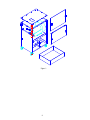
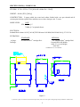
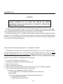
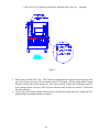
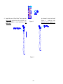
The Local Exhaust & Ventilation Company Inc. 22-1050 Brock Rd, Pickering, Ontario L1W 3X4 Tel: 905.831.7001 Fax: 905.831-7443 Toll Free: 1.888.862.5356 E-mail: [email protected] Web Site: www.lev-co.com OWNERS MANUAL MODEL V410 (INCLUDES VIBRAPULSE CLEANING SYSTEM*) • INTRODUCTION • SPECIFICATIONS • UNPACKING • INSTALLATION • MOUNTING • ELECTRICAL • OPERATION • MAINTENANCE • TROUBLESHOOTING • REPLACEMENT PARTS • MOTOR TROUBLE GUIDE ***IMPORTANT*** THIS MANUAL CONTAINS PRECAUTIONARY STATEMENTS RELATING TO WORKER SAFETY. READ AND SAVE THIS MANUAL COMPLETELY AND COMPLY AS DIRECTED. ALL THE POTENTIAL HAZARDS OF DUST AND MIST CONTROL SYSTEMS AND EQUIPMENT ARE IMPOSSIBLE TO LIST; THEREFORE, OBTAIN THE SERVICES OF A PROFESSIONAL INSTALLER. A FIRE PROTECTION EXPERT SHOULD BE OBTAINED IN THE EVENT THE PRODUCT IS INTENDED FOR USES WHICH PRESENT A POTENTIAL RISK OF FIRE OR FIRE PROPAGATION. REFER TO APPROPRIATE AUTHORITIES, AND DISCUSS YOUR INTENDED USE WITH YOUR LOCAL DISTRIBUTOR OR AIRFLOW SYSTEMS, INC. WORKERS HANDLING EQUIPMENT OR SYSTEMS SHOULD BE INSTRUCTED TO CONDUCT THEMSELVES IN A SAFE MANNER. PART # 4KT11067 (REV 4/99/-/#32-2142) *PATENT APPLIED FOR 3 ALWAYS USE AIRFLOW SYSTEMS, INC. REPLACEMENT PARTS AND FILTERS TO MAINTAIN WARRANTY. TO ORDER SPARE PARTS CONTACT: The Local Exhaust & Ventilation Company Inc. 22–1050 Brock Rd, Pickering, Ontario L1W 3X4 Tel: 905.831.7001 Fax: 905.831.7443 Toll Free: 1.888.862.5356 E-mail: [email protected] Web Site: www.lev-co.com 4 TABLE OF CONTENTS 1. Safety.............................................................................................................................. 4 2. Airflow Systems Sets the Standard ............................................................................... 5 3. Specifications .................................................................................................................. 6 4. Inspection ....................................................................................................................... 7 5. Preparation and Installation .......................................................................................... 7 6. Compressed Air Supply ................................................................................................. 7 7. Vibra Pulse Filter Cleaning System............................................................................. 7 8. Electrical......................................................................................................................... 8 Three phase............................................................................................................ 8 9. Operation........................................................................................................................ 9 10. Maintenance................................................................................................................... 10 Vibra Pulse System - Hose Replacement ......................................................... 10 11. Filter Service .................................................................................................................. Filter Replacement/Removal for Cleaning .......................................................... Filter Cleaning - Vibra Pulse System................................................................. HEPA Filters ......................................................................................................... AD Module ............................................................................................................ 13 13 14 15 15 12. Other Service ................................................................................................................. 15 13. Replacement Parts ......................................................................................................... 16 14. Troubleshooting.............................................................................................................. 18 15. Notes............................................................................................................................... 19 16. Appendix......................................................................................................................... 20 5 READ THIS MANUAL CAREFULLY BEFORE ATTEMPTING TO INSTALL OR OPERATE THE MODEL V410 UNIT. RETAIN THESE INSTRUCTIONS FOR FUTURE REFERENCE. SAFETY RULES Follow all electrical and safety codes as well as the National Electrical Code (NEC), National Fire Protection Association (NFPA), and the Occupational Safety and Health Act (OSHA). All electrical connections and wiring should be performed by qualified personnel only. National Fire Protection Association (NFPA) standards require specific duct design and dust collector configuration when collecting potentially reactive metal dusts, such as aluminum and magnesium, and other materials. NFPA also covers other dusts such as grain, plastics, etc. A guideline for determining the precautions to be taken can be found in NFPA 497. Other NFPA standards may apply to your specific application. Consult current NFPA standards, available from NFPA, 1 Batterymarch Park, Quincy, MA, 02269, 1-800-344-3555, for applicable safeguards which may required for the Installation, Operation, and Service of this product. Fire suppression equipment provided by others. Additional references are the Uniform Building Code and Uniform Mechanical Code. WARNING APPLICATION OF DUST CONTROL EQUIPMENT: 1. Do not mix materials being collected by a dust collector unless it is determined that mixing of materials does not cause hazardous conditions to occur or creates a condition of operation for which the equipment was not intended. 2. Under no condition should burning cigarettes or any burning object be allowed into the hood or ducting of any dust control system. 3. When dust collectors are used to collect emissions from steel or combined metal sanding, the dust collector should be located an adequate distance away to minimize the chance of ignition of duct system residue from hot metal chips and sparks. Should further protection from fire be required, adequate duct systems from capture hoods and dust collector should be provided so that a fire protection specialist can install extinguishing equipment. You may also want to contact your insurance underwriter. 4. Explosion relief vents may be required per NFPA codes. Explosion vents are used to minimize the destructive effect of an explosion and are intended primarily to protect from injury anyone in the immediate area of the collector. Damage to the collector may, or may not, be repairable. Vents installed on dust control equipment within a building must be vented to the outside to minimize chances of injury to persons or a secondary explosion. Again, consult the proper authority to determine proper method of venting. Explosion relief vents are optional and should be ordered with the dust collector or installed locally. 6 5. Always disconnect unit from power source before inspecting or servicing. AIRFLOW SYSTEMS SETS THE STANDARD The Airflow Systems Model V410 collects dust, welding smoke, and other dry pollutants in industrial plants, shops, schools and factories. The general theory of operation is that air bearing pollutants passes o through the inlet and must make a 180 turn to pass through a spark screen where large particles fall out of the air stream. The particulate laden air then passes through the (2) main 95% cartridge filters where the +1 and sub-micron particles are captured. The main filters have 150 ft2 collection area each for maximum intervals between service. The Vibra Pulse is for filter cleaning with dry dust applications. After passing through the filters, the cleaned air is then discharged thru the top of the unit. Figure 1 shows general construction details. The Model V410 is a complete portable collector. The unit comes equipped with four 5" industrial duty casters (2 swivel, 2 fixed). It comes standard with (2) 3” FPT couplings for attachment of collection hoses. The Model V410 can be mounted in a stationary location if desired by ordering it with the optional hopper and stand kit. The Model V410 is available with an external 99.97% HEPA filter or Adsorption Module (AD) if required. 7 Figure 1. 8 SPECIFICATIONS(*): MODEL V410 STD DIM: 36" W x 26" D x 53" H [0.91m W x 0.66m D x 1.35m H] WEIGHT: 680 lb. (STD) [309 kg] CONSTRUCTION: 12 gauge welded zinc coated steel cabinet, finished with a two part chemical and oil resistant paint. Includes separate filter and blower access doors, dust pan, and 5" casters. NOISE LEVEL: 10 HP STD 76 dBA @ 5’ 72 dBA @ 5' w/optional silencer ELECTRICAL: Standard Blower Motor: 10 HP [7.46 kW] TEFC BB motor 3450 RPM, 208-230/460/3/60 @ 27.3-25/15 A FILTRATION: STANDARD 1st Stage: 2nd Stage: OPTIONAL 16” Dia CLEAN 2 cartridge filter* 16” Dia Fiber Dust cartridge filter* External HEPA/AD Module (Adds 15” to overall height) AutoClean * ASHRAE 52-76 Test Method Figure 2. (*) AFS has a policy of continuous research and improvement, and reserves the right to change design and specifications without notice. 9 INSPECTION AND UNPACKING Inspect your AFS unit for shipping damage immediately upon receipt. Damaged carton(s), broken crate(s), etc. are indications that the unit may have been damaged in shipment. It is also possible shipping damage may be concealed and not noticed until the unit is installed and in operation. If any damage is found, notify your delivery carrier at once and enter a claim. Claims must be filed within 15 consecutive days of receipt of shipment. FREIGHT DAMAGE CLAIMS ARE THE RESPONSIBILITY OF THE PURCHASER, NOT AIRFLOW SYSTEMS. PREPARATION AND INSTALLATION After initial inspection for shipping damage, check the cabinet filter and motor/blower compartments for any packing materials and remove. Install casters, then stand unit upright and attach pickup hoses to 3" inlets. Use correct lifting devices to prevent damage or injury. Roll unit to the desired location. When using an extension cord with a portable air cleaner, refer to the Appendix and Motor Troubleshooting Guide Table A for the correct wire gauge. The following section discusses both physical installation and electrical tie in. Fire suppression equipment provided by others. COMPRESSED AIR SUPPLY Effective cleaning of the filters in most applications will occur when the pressure at the compressed air connection of the air cleaner is maintained, while the filter is cleaning, of 80 PSI. Pressure over 100 PSI is NOT recommended at any time, and generally reduces cleaning performance. A pressure below 70 PSI may decrease cleaning effectiveness in some applications. A nominal ( OFF or not cleaning ) pressure setting of 80 PSI is usually adequate when using a 3/8” compressed air supply line. If optional regulator/gauge is installed, set regulator to 80 PSI. When air valve is open, confirm pressure on gauge does not go below 70 PSI. Compressed air filter provided by others. Fire suppression equipment provided by others. VIBRA PULSE FILTER CLEANING SYSTEM To set up the Vibra Pulse system, simply slide the 3/8” air hose over the hose barb fitting on the outside of the cabinet and secure it with the 1” hose clamp. Refer to Figure 3. Use any standard Quick Disconnect 3/8” fitting (as used on an air tool) to attach to the supply air. The V410 unit comes with 10’ of 3/8” air line. If a longer run of hose is required, it is recommended to use a continuous piece of hose to avoid splicing, as this will reduce the compressed air available to the unit. Always use 3/8” air line with this unit. Once the air is attached to the unit, set the line pressure to 80 PSI (see Compressed Air Supply section). It is recommended to use a separator/drier on the air line to prevent any debris from fouling the actuator valve. Compressed air filter provided by others. Test the system by pressing and pulling the actuator valve on the side of the 10 unit (See the MAINTENANCE Section for more details). If any problems are found, consult the TROUBLESHOOTING Section in this manual. ELECTRICAL All 3 phase AC Model V410 units have wiring terminated inside the junction box located on the side of the unit. Motor starters and disconnects are not supplied with the unit (unless purchased as an option), and must meet local and National Electrical Code. Motors are typically multiple voltage type (e.g. 208/230/460). Make sure connections in motor junction box correspond to the line voltage you plan to use. Three phase motor starters (manual or magnetic type) must have properly sized thermal overloads for the voltage and current required at the motors. All units are required to have a motor voltage and current check performed at startup. Motor checkout should be performed with the unit running, all filters in place and cabinet doors closed. Measured motor current readings should be equal to or below motor nameplate rating. These specifications can be found on the motor name plate or in the specifications section of this manual. If the motor amp draw does not fall within the Full Load Rating (FLA) refer to the TROUBLESHOOTING Section of this manual. THREE PHASE MOTORS Three phase motors do not have overload protection included in the standard configuration and must be supplied by the end user, see Figure 4 or page A3 of the Appendix. They are also available from the factory as a pre-installed option. If these protective circuits are not ordered from the factory, use equipment as specified by the National Electric Code or other applicable authority. On the three phase models, the motor can operate in either direction, and the fan will pump air in either direction. However, for proper suction and airflow, the blower motor should be turning in a manner such as to create a suction at the (2) 3” inlets. To verify the correct rotation, bump start motor (turn on briefly then turn off) and feel the 3” inlet coupling on side of unit. There should be a suction. If air is blowing out, reverse any two wires of the in-coming power and motor will reverse direction (3 PHASE ONLY). Figure 5 shows details on Figure 4. changing the wiring configurations. The main power leads, L1, L2, and L3 are not differentiated by color. If motor rotation must be changed, then reversing any two of the leads will produce this result (e.g. reverse. L1 and L2 or L2 and L3). Figure 6 shows the voltage configuration hook-ups on the A2 three phase motor. Consult the motor name plate and verify the line input voltage before attempting to make this change. Figure 6. Figure 5. CAUTION IN LARGE PLANTS, WHEN ROLLING UNIT FROM ONE BUILDING TO ANOTHER, YOU MAY BE ON A DIFFERENT SUBSTATION TRANSFORMER. UNITS USING A THREE PHASE BLOWER MOTOR MAY RUN BACKWARDS. CHECK ROTATION IN EACH LOCATION WHERE THE UNIT WILL BE USED TO ENSURE THAT BLOWER MOTOR ROTATES IN PROPER DIRECTION. REVERSING SWITCHES ARE AVAILABLE IF REQUIRED. CAUTION CABINET DOORS MUST BE CLOSED WHEN OPERATING THE BLOWER. MOTOR WILL BE OVERLOADED IF RUN WITH THE FILTER DOOR OPEN. OPERATION Operation of the Model V410 is very straight forward. Roll the unit to the desired work area and arrange it so that no equipment will come into contact with the unit. Simply switch the unit ON when smoke or dust collection is required. Remember to always turn the unit OFF when cleaning the filters. WARNING DO NOT OVER-EXTEND THE UNIT POWER CORD REACH. DISCONNECTING THE POWER SOURCE WHILE UNIT IS IN OPERATION CAN CAUSE SPARKING. A3 MAINTENANCE WARNING ALWAYS DISCONNECT THE UNIT FROM THE POWER SOURCE BEFORE WORKING ON OR NEAR THE MOTOR OR WIRING ASSEMBLIES. LOCK OUT DISCONNECTS TO PREVENT UNEXPECTED APPLICATION OF POWER. The Model V410 comes standard with (2) CLEAN 2 filter cartridges of 150 square feet of media each. An optional External Module is available for a final filter. This external module can house either a HEPA filter or an adsorption bank (AD). Filter access is from the top cover of the module. The Adsorption Module (AD) is a refillable, finely perforated container to hold the adsorption material in the air flow. As with the HEPA, it is located on top of the unit. The AD utilizes the same mounting method as described above. The AD module has a 2" 30% poly after-filter to remove any carbon (or other) dust that occurs from adsorption material breakdown. VIBRA PULSE SYSTEM MAINTENANCE - HOSE REPLACEMENT The Vibra Pulse hose that is used to clean the filter will eventually wear out. Check for signs of excessive wear when doing normal filter service or if a decrease in filter cleaning effectiveness is observed. A hose should be replaced when it has worn to a length of 6”. Replacement of the hose is a simple operation. With the unit turned off, disconnect power and lock out. CAUTION: Disconnect Air Supply before working on unit. Proceed as follows to accomplish the hose replacement. 1. 2. 3. 4. 5. 6. Turn unit off. Disconnect power and lock out. Disconnect air supply before working on unit and lock out. Remove filter access door. Remove cartridge filter(s) from unit. Remove dust tray and dispose of material in accordance with local, state, and federal regulations. The Vibra Pulse actuator mechanism consists of the following: 1 fixed and 3 loose components (per filter), see Figure 7. a. Fixed component is the 3/8” rigid hose barb attached to the Vibra Pulse Plenum chamber b. The loose components involved in the replacement operation consist of: 1 - Reusable spring (7PR1-2004) 1 - Reusable hose clamp (7HG3-1003) A4 1 - Hose (2VP2-1012), quantity as required by applicable unit (1 hose per cartridge). Figure 7. 7. Remove the old Vibra Pulse hose. This is done by loosening the hose clamp securing the spring at the top of the VP hose where the VP hose attaches to the 3/8” hose barb. Slide the spring and hose clamp down the VP hose and set aside for later use. Next, remove the old VP hose, this is sometimes easiest to do by cutting the hose at the top, where it fits over the hose barb, to allow free removal. Discard old hose after removing. 8. Loosely place hose clamp (retained from step above) into the first closed loop of the spring after first opening clamp to maximum diameter, see Figure 8. A5 9. Install the new Vibra Pulse hose onto the fully seated against brass hex on barb, see water or Windex to ease installation. Do lubricant! Figure 8. Figure 9. A6 air cleaner’s hose barb until Figure 9. Lubricate with not use oil or grease as 10. Slide the spring/clamp up over the hose and 3/8” hose barb until it fully seats against the barb’s hex, see Figure 10. 11. Tighten the hose clamp using screw driver or 1/4” nut runner. DO NOT OVERTIGHTEN! 12. Replace filter(s) into unit. Note: Make sure NOT to pinch hose - position Vibra Pulse hose into the center of the cartridge filter. Engage filter mechanism if required. 13. Reinstall dust tray. 14. Reinstall filter access door. 15. Reconnect air line and power. 16. Test the Vibra Pulse system for operation manually or electrically as appropriate for your unit’s configuration. Figure 10. FILTER SERVICE The filters have been charged with pre -coat (an inert white mineral dust) at the factory. This precoat material will increase initial efficiency and help to extend the cartridge filter life. Upon initial unit start up, go through one cleaning cycle (see filter cleaning below), most of the pre-coat will be removed from the filter and fall into the dust pan. The remaining pre-coat will stay on the filters. Save any material that falls into the pan for treating replacement filters. A Material Safety Data Sheet (MSDS) will be furnished upon request. Please contact the Airflow Systems Representative or the AFS Factory. Filter service is required when a reduction of airflow (suction) is observed. The optional pressure gauge is used to judge the amount of particulate collected on the filter. As the worker gets accustomed to the units’ effectiveness of capture, and the associated gauge reading, the gauge can then become an indicator of filter condition. The optional pressure gauge is calibrated as follows: In most applications, with clean filters, turn unit on and mark the pressure reading on the gauge. Make a second mark at 2.0" higher than initial reading (i.e. if initial reading is 3.0" the second mark should be at 5.0"). Note that a reading of 5.0” is typical of when the filter should be cleaned in most applications. NOTE Unit can continue to run safely beyond the 5.0 " pressure differential recommended, however performance will be reduced. Exceeding 6.0" pressure differential across the filter may cause reduced filter life. A7 FILTER REPLACEMENT/ REMOVAL FOR CLEANING 1. Turn unit OFF and disconnect from power source. 2. Remove filter access panel. 3. Release filter retaining latch located between cartridges, (see Figure 11.) This will lower the filter holding frame. Unhook latch to let holding frame rest at lowest position. 4. Remove filters, being careful not to damage the Vibra Pulse hose which hangs suspended in the center of each filter. 5. To replace, reverse above procedure. Avoid inadvertently trapping the Vibra Pulse hose between filter end cap and cabinet. Also, make certain that the filters are not cocked. (A cocked filter will not properly seal to the blower inlet, resulting in significant contaminant by-pass.) Figure 11. FILTER CLEANING - VIBRA PULSE SYSTEM 1. Turn unit OFF and let motor/blower come to a complete stop. 2. Connect the 3/8” airline (supplied) to REGULATED shop air (80 PSI, see Compressed Air Supply section). Compressed air filter provided by others. 3. PRESS and hold the pulse cleaning button in for 5 - 10 seconds. Next, PULL the button outwards for 5 - 10 seconds. This will clean the other side of the filter. Repeat this process 2 or 3 times. See Figure 12. 4. Open the filter access door. Remove and empty the dust tray in the bottom of the unit. This will prevent the dust from recollecting on the filter when the unit is restarted. Close door. 5. Turn the unit ON and check suction and/or pressure gauge. If additional Figure 12. cleaning is needed repeat the steps listed above. (During multiple cleanings, some dust may come out of the hose or blower outlet. This is normal.) 6. If the filters are overloaded, in-place cleaning may not dislodge all of the collected dust. The filter will need to be removed and tapped out in the dust pan or replaced with a new filter. DO NOT BLOW OFF WITH COMPRESSED AIR DUE TO POSSIBLE OVER-EXPOSURE OF WORKERS AND POTENTIAL FILTER DAMAGE. 7. Any moisture such as oil or water on the filter will cause shortened filter life. If the filters plug with dirt due to oil or water, they may not pulse clean. (See Note below.) 8. If shop air is not clean and dry it may be necessary to install an airline filter/drier to prevent premature filter replacement. CAUTION A8 IT IS IMPORTANT TO USE ONLY CLEAN AND DRY COMPRESSED AIR TO CLEAN THE FILTERS, OTHERWISE CONTAMINATION TO CARTRIDGE FILTER ELEMENT WILL RESULT. DO NOT HOOK UP TO A COMPRESSED AIR LINE THAT HAS AN AUTOMATIC OILING DEVICE ON IT. OIL OR WATER WILL MAKE CLEANING DIFFICULT AND SHORTEN THE FILTER LIFE. NOTE Not all applications will self-clean. Sticky or oily dust may not dislodge from the filter. In this case, the filters must be cleaned or replaced. HEPA FILTER: (On models equipped with optional external module) cannot be cleaned. See your distributor for replacement. AD MODULE: (On models equipped with optional external module.) The adsorption material (activated carbon or other) can be emptied from the module and refilled with fresh adsorber. Refer to the Figure 13. Use the large opening to fill the majority of the module. After as much material can be put in as possible, use the small filler hole on the end to top off module. It is important to get the AD module as full as possible as any low spots or air gaps will allow the gas being captured to by-pass or be exposed to a reduced amount of scrubbing. Always dispose of the spent adsorption material in accordance with local, state and federal regulations. Figure 13. The module is refillable as follows: 1. Remove module and take to a well ventilated area: DUST IS RELEASED DURING THE REFILLING OPERATION. 2. Remove cover plate and empty contents of module into a plastic bag or other approved container. WEAR ADEQUATE PERSONAL PROTECTIVE DEVICES. A9 3. Refill with the new adsorber material. After refilling, shake module to pack granules tightly before replacing cover plate to make sure module is full. Remove the end cover plate and top-off any void in the module. 4. Vacuum any excess carbon dust that occurs from settling during handling. After re-installing, stay clear of the unit outlet area as some dust may be expelled when unit is first turned on. The unit should be test run after each refilling operation. OTHER SERVICE Most other components of your Model V410 air cleaner require little or no routine servicing. Items such as motor/blower, tubing, and gaskets should be checked twice a year under normal usage; more frequently under severe 24-hour-per-day usage. Clean, repair, or replace parts as necessary. Replacement parts are available from your Airflow Systems distributor. The following section lists replacement parts for the Model V410 unit. A10 REPLACEMENT PARTS The following section lists typical replacement parts for the Model V410 . If a part is not listed in Table 2, contact your local Airflow Systems Representative or the AFS Factory. Refer to Figures 14 and 15 for parts illustrations. TABLE 2. ITEM 1 2 2 3 4 5 6 7 8 9 10 11 12 13 14 15 16 N/S N/S N/S N/S N/S N/S N/S N/S PART NUMBER 7BM4-6301 7HG1-5011 7HG1-5012 7VA6-1002 1PL3-2730 7PH3-1005 1PN3-2731 7PH3-4002 7KB2-3001 1PN3-2735 7PH3-8003 7HG4-3002 1PN3-2740 1AC5-7743 1CH5-4003 7HG4-6001 7HG4-1002 2VP2-1012 7PR1-2004 7FR0-2016 7FR0-2017 7FH9-9112 7FH9-5112 7FV0-0312 7FM8-8000 QTY 1 2 2 1 1 A/R 1 A/R 2 1 A/R 2 1 1 1 1 1 2 2 2 2 1 1 1 1 DESCRIPTION Motor, 10 HP, 208-230/460/3 VAC, (OPT) 5" Caster, Rigid 5" Caster, Swivel Vibra Pulse Control Valve Top Plate Top Panel Gasket Blower Access Door Blower Access Door Gasket Knobs, Door Retaining Filter Access Door Filter Access Door Gasket Lift-Turn Latch Dust Tray Filter Lift Latch Channel Filter Latch Latch Strike Vibra Pulse Hose Spring, Vibra Pulse Hose CLEAN 2 Cartridge Filters, Std. Fiber Dust Cartridge Filters, Opt. 99.97% External HEPA filter, Opt. 95% External D.O.P. filter, Opt. External AD filter, Opt. 2” Polyester afterfilter (used w/AD), Opt. USE ONLY AUTHORIZED AIRFLOW SYSTEMS REPLACEMENT PARTS AND FILTERS TO PREVENT VOIDING THE WARRANTY. A11 Figure 14. Model V410 filter lifting assembly. Figure 15. A12 Model V410 general assembly. TROUBLESHOOTING The troubleshooting guide included in this manual is for qualified personnel only. A Motor Trouble Guide is included in Appendix A. If the unit does not function properly after following the guidelines in this manual, consult an Airflow Systems Representative for further help. PROBLEM 1. Motor won't operate POSSIBLE CAUSE Motor overload Failed motor Starter failure No input voltage 2. Motor runs, then trips out Voltage source inadequate overload or blows fuses 3. Low air flow 4. Vibra Pulse not effective CORRECTIVE ACTION Too much airflow. Be sure arm, hose (or ducts),and doors are installed before running. Replace motor. Check amps to ensure proper operation. Check overload reset. Check magnet coil for failure Check circuit breaker Check voltage at motor with motor running. Voltage should be +/- 10% of motor rating. If not, check: 1. Power source 2. Wire size from source Check running amps of motor. If at or below amps indicated on unit nameplate, check fuse size or overload sizing/adjustment. Static load on blower too low Increase system duct inlet resistance Duct disconnected Prefilter/filter plugged Motor running backwards (3 phase only) Motor running slow Inspect and repair Clean filter Check rotation. Air pressure too low Minimum 70 PSI (see Compressed Air Supply section) Use 3/8” hose (supplied) Check hose. Flush valve and install filter Inspect or replace Inspect and correct Use minimum 3/8” size Air hose too small Air hose blocked/leaking Air valve plugged Vibra Pulse hose loose/damaged Vibra Pulse hose pinched in filter Quick disconnect too small A13 Check line voltage Check motor current NOTES RECORD START UP DATA HERE MODEL: V410 SERIAL NO.: DATE PURCHASED: DATE INSTALLED: MOTOR VOLTAGE (MEASURED): MOTOR CURRENT (MEASURED): MOTOR FLA (FROM NAMEPLATE): MOTOR VOLTAGE (FROM NAMEPLATE): ALWAYS USE AIRFLOW SYSTEMS REPLACEMENT PARTS AND FILTERS TO MAINTAIN WARRANTY TO ORDER SPARE PARTS CONTACT: The Local Exhaust & Ventilation Company Inc. 22–1050 Brock Rd, Pickering, Ontario L1W 3X4 Tel: 905.831.7001 Fax: 905.831.7443 Toll Free: 1.888.862.5356 E-mail: [email protected] Web Site: www.lev-co.com A14 APPENDIX 1. BRANCH WIRING ............................................................................... A1 2. MOTOR TROUBLE GUIDE ................................................................. A2 3. TYPICAL INSTALLATION WIRING DIAGRAM ................................ A3 4. 4KT11096 - OWNERS MANUAL ADDENDUM – OPTIONAL AUTOCLEAN CONTROLLER SYSTEM........................................................ A4 5. OWNERS MANUAL ADDENDUM – STATIC PRESSURE RELIEF VALVE ................................................................................................. A5 A15 MOTOR WIRING GUIDE (BRANCH CIRCUIT) WIRING To connect motor for proper voltage and rotation, refer to connection diagram on nameplate or inside terminal/conduit box. If power factor correction capacitors are used for individual motor power factor correction, do not exceed maximum recommended value. All aspects of the installation must conform to the requirements of the NEC, including Article 430 (Motor Circuits and Controllers), and all local codes. Wherever possible, each motor should be powered from a separate circuit of adequate capacity to keep voltage drop to a minimum during starting and running. Increase wire size where motor is located a distance from the power source. Wire size must be adequate to minimize voltage drop during starting and running. Refer to Tables A and B for suggested wire sizes. Distances shown are one-way between source and load. Portable cords, if used, should be as short as possible to minimize voltage drop. Long or inadequately sized cords, especially on hard starting loads, can cause motor failure. Insulate and protect motor lead connections to prevent cut-through from sharp edges and vibration. Tape wire nuts to prevent loosening. All electrical connections in system must be secure to prevent voltage drop and localized heating. Determine direction of rotation before connecting driven equipment to prevent damage. Remove shaft key if motor is to be operated at no-load. On three phase motors, interchange any two line leads (not motor leads) to reverse rotation. On air compressors, rotation of flywheel should direct air towards the cylinders. Look for rotational arrow on flywheel. All motors must be securely and adequately grounded by wiring with a grounded, metal-clad raceway system, using a separate ground bond wire connected to bare metal on the motor frame, or other suitable means. Refer to NEC Article 250 (Grounding) for additional information. Explosion-proof motors incorporating over temperature thermostats should be controlled with a magnetic starter. The thermostat circuit must be wired in series with the holding coil circuit, as shown on tag or nameplate on motor, to remove power from the starter coil if motor overheats. TABLE A - MINIMUM WIRE SIZES FOR THREE-PHASE MOTORS MOTOR HP 1/8 25 FT TO 50 FT 100 FEET 150 FT TO 200 FT 200V 230V 460V 200V 230V 460V 200V 230V 460V 14(18) 14(18)* 14(18)* 14(18) 14(18)* 14(18)* 14(16) 14(18)* 14(18)* * * * 1/6 14(18) 14(18)* 14(18)* 14(18) 14(18)* 14(18)* 14(16) 14(16)* 14(18)* * * * 1/4 14(18) 14(18)* 14(18)* 14(16) 14(18)* 14(18)* 14 14 14(18)* * * 1/3 14(18) 14(18)* 14(18)* 14(16) 14(16)* 14(18)* 12 14 14(18)* * * 1/2 14(16) 14(18)* 14(18)* 14 14 14(18)* 10 12 14(18)* * 3/4 14 14(16)* 14(18)* 12 14 14(18)* 8 10 14(16)* 1 14 14(16)* 14(18)* 10 12 14(18)* 8 10 14 1½ 12 14 14(18)* 10 10 14(16)* 6 8 14 2 12 12 14(18)* 8 10 14(16)* 6 6 12 3 10 12 14(18)* 8 8 14 4 6 12 [*]Type S, SO, SJ, SJO, etc. flexible cable wire sizes. See NEC Article 400 for ampacity . Note: Above wire sizes based on approximate 5% voltage drop during starting; copper conductors; and 75°C type TH, THW, RH, RHW, etc. insulation. For aluminum wire, increase two wire size steps minimum. See NEC Article 310 for ampacities of aluminum conductors and 60°C type RUW, T, etc. insulation. TABLE B - MINIMUM WIRE SIZES FOR SINGLE-PHASE MOTORS MOT0R 25 FT 50 FT 100 FT 150 A16 FT 200 FT HP 1/8 115V 14(16) * 14 230V 115V 230V 115V 230V 115V 230V 115V 230V 14(18) 14 14(18)* 10 14(16) 10 14(16) 8 14 * * * 1/6 14(18) 12 14(18)* 10 14(16) 8 14 6 12 * * 1/4 14 14(18) 12 14(18)* 8 14 6 12 6 12 * 1/3 14 14(18) 10 14(16)* 8 14 6 12 4 10 * 1/2 14 14(18) 10 14(16)* 8 14 6 12 4 10 * 3/4 12 14(18) 8 14 6 12 4 10 3 8 * 1 10 14(16) 8 14 4 10 4 8 2 8 * 1½ 10 14(16) 6 12 4 10 2 8 1 6 * 2 8 14 6 12 3 8 2 6 1/0 6 3 8 10 4 10 2 8 1/0 6 2/0 4 [*] Type S, SO, SJ, SJO, etc. flexible cable wire sizes. See NEC Article 400 for ampacity. Note: Above wire sizes based on approximate 5% voltage drop during starting; copper conductors; and 75°C type TH, THW, RH, RHW, etc. insulation. For aluminum wire, increase two wire size steps minimum. See NEC Article 310 for ampacities of aluminum conductors and 60°C type RUW, T, etc. insulation. MOTOR TROUBLE GUIDE The purpose of this guide is to suggest common answers to electrical problems. The information is not all-inclusive and does not necessarily apply in all cases. When unusual operating conditions, repetitive failures, or other problems occur, consult an electric motor service firm for assistance. TROUBLE CAUSE WHAT TO DO MOTOR FAILS TO START 1. Blown Fuses. 1. Replace with time-delay fuses or circuit breakers. Check for grounded winding. 2. Use higher voltage tap on transformer terminals, increase wire size. Check for poor connections. 3. Check connections against diagram supplied with motor. 4. Check and reset overload relay in starter. Check heater rating against motor nameplate current rating. Check motor load. If motor has manual reset thermal protector, check if tripped. 5. Reduce load. Increase motor size. 6. Indicated by humming sound. Replace run capacitor. See nameplate for correct value. 7. Repair or replace. 2. Low voltage. 3. Improper line connections. 4. Overload (thermal protector) tripped. 5. Motor may be overloaded. 6. If permanent split capacitor motor, capacitor may be open. 7. Defective motor or starter. MOTOR STALLS 1. Overloaded motor. 2. Low motor voltage. MOTOR DOES NO T COME UP TO SPEED 1. Not applied properly. 2. Voltage too low at motor terminals due to line drop. A17 1. Reduce load or increase motor size. 2. See that nameplate voltage is maintained. 1. Consult motor service firm for proper type. Use larger motor. 2. Use higher voltage tap on transformer terminals, increase wire size. Check for 3. Load too high. MOTOR TAKES TOO LONG TO ACCELERATE 1. Excess Loading; high inertia load. 2. Inadequate wiring. 3. Applied voltage too low. 4. Defective motor. 5. Inadequate starting torque. MOTOR VIBRATES OR IS EXCESSIVELY NOISY 1. Motor mis-aligned. 2. High voltages. 3. Worn, damaged, dirty or overloaded bearings. 4. Loose or defective or out-of-balance air mover. INSUFFICIENT SPEED CHANGE 1. Insufficient motor load. MOTOR OVERHEATS WHILE RUNNING UNDER LOAD 1. Overload. 2. Dirt preventing ventilation. 3. Faulty connection. 4. High or low voltage. 5. Defective motor. poor connections. 3. Check load motor is carrying at start -replace with larger motor. 1. Reduce load. Increase motor size. 2. Increase wire size. Check for poor connections. 3. Reconnect to a higher transformer tap. Increase wire size. Check for poor connections. 4. Repair or replace. 5. Replace with higher horsepower motor. 1. Realign. 2. Check wiring connections, transformer. 3. Replace, check loading and alignment. 4. Tighten set screw(s); repair or replace. 1. Use a lower horsepower motor. 2. Reduce system restrictions (blower). Increase system restriction (propeller fan). 1. Reduce load; increase motor size. 2. Clean motor. 3. Clean, tighten or replace. 4. Check voltage at motor, should not be more than 10% above or below rated. 5. Repair or replace. A18 TYPICAL INSTALLATION WIRING DIAGRAM A19 The Local Exhaust & Ventilation Company Inc. 22-1050 Brock Rd, Pickering, Ontario L1W 3X4 Tel: 905.831.7001 Fax: 905.831-7443 Toll Free: 1.888.862.5356 E-mail: [email protected] Web Site: www.lev-co.com OWNERS MANUAL ADDENDUM OPTIONAL AUTOCLEAN CONTROLLER SYSTEM MODELS: PC / PC-2 / DC-1 / DC-2 / DT-3000 DT-800 / V-2 / V410 • INTRODUCTION SPECIFICATIONS • UNPACKING • INSTALLATION • ELECTRICAL • OPERATION • MAINTENANCE • REPLACEMENT PARTS • *****IMPORTANT***** THIS MANUAL CONTAINS PRECAUTIONARY STATEMENTS RELATING TO WORKER SAFETY. READ AND THIS MANUAL COMPLETELY AND SAVE. COMPLY AS DIRECTED. ALL THE POTENTIAL HAZARDS OF DUST AND MIST CONTROL SYSTEMS AND EQUIPMENT ARE IMPOSSIBLE TO LIST; THEREFORE, OBTAIN THE SERVICES OF A PROFESSIONAL INSTALLER. A FIRE PROTECTION EXPERT SHOULD BE OBTAINED IN THE EVENT THE PRODUCT IS INTENDED FOR USES WHICH PRESENT A POTENTIAL RISK OF FIRE OR FIRE PROPAGATION. REFER TO APPROPRIATE AUTHORITIES, AND DISCUSS YOUR INTENDED USE WITH YOUR LOCAL DISTRIBUTOR OR AIRFLOW SYSTEMS, INC. WORKERS HANDLING EQUIPMENT OR SYSTEMS SHOULD BE INSTRUCTED TO CONDUCT THEMSELVES IN A SAFE MANNER. A20 PART# 4KT1-1096 (REV 11/98/A/#26-1894) A21 ALWAYS USE AIRFLOW SYSTEMS, INC. REPLACEMENT PARTS AND FILTERS TO MAINTAIN WARRANTY. TO ORDER SPARE PARTS CONTACT: The Local Exhaust & Ventilation Company Inc. 22–1050 Brock Rd, Pickering, Ontario L1W 3X4 Tel: 905.831.7001 Fax: 905.831.7443 Toll Free: 1.888.862.5356 E-mail: [email protected] Web Site: www.lev-co.com 3 TABLE OF CONTENTS 1. Safety......................................................................................................................... 4 2. Airflow Systems Sets the Standard .......................................................................... 4 3. Specifications ............................................................................................................. 4 Electrical........................................................................................................... 4 4. Inspection .................................................................................................................. 4 5. Preparation and Installation ..................................................................................... 5 6. Electrical.................................................................................................................... 5 Single phase....................................................................................................... 6 Three phase ....................................................................................................... 7 7. Autoclean Unit Operation......................................................................................... 9 8. Maintenance.............................................................................................................. 10 9. Replaceme nt Parts.................................................................................................... 10 3 3 READ THIS MANUAL CAREFULLY BEFORE USING AUTOCLEAN EQUIPPED UNIT. RETAIN THESE INSTRUCTIONS FOR FUTURE REFERENCE. SAFETY RULES Before installing or operating this system, read this supplemental Owners Manual. All safety and cautionary notes from the primary Owners Manual are in effect after installation of the AUTOCLEAN system. As with all electrical devices, it should only be serviced by a qualified electrical technician. AIRFLOW SYSTEMS SETS THE STANDARD The AUTOCLEAN filter cleaning control system automatically controls off line cleaning of the filters in the equipment. Automatic operation assures the filters are cleaned regularly to assure peak equipment operating performance and filter life. The system uses a timer sequence circuit board to activate from one to five filter cleaning stations. User adjustments of cartridge cleaning duration, frequency of cleaning cycles and time between individual filter cleaning times are easily set on the board. In the case of the single filter systems, the duration of the cleaning is controlled by a time delay relay. SPECIFICATIONS ELECTRICAL: Standard Input Voltage: 115 VAC single phase, 60 cycles ( Higher input voltages available when used with a step-down transformer. ) AFS has a policy of continuous research and improvement, and reserves the right to change design and specifications without notice. INSPECTION AND UNPACKING Immediately upon receiving the unit, carefully examine the unit for damage during transit. If the unit is damaged, note on the Bill of Lading or contact the last carrier for filing a claim within 10 working days. Even if there is no visible exterior damage to the shipping container, there may be CONCEALED damage that could be caused by improper handling during shipping. Unpack the unit, saving all packaging materials, and examine the contents carefully. If there is internal damage to the unit, it must be reported to the last carrier and a claim filed within 10 working days. The damage inspector will want to see the damaged unit and all of the packing materials. 4 PREPARATION AND INSTALLATION Through out this manual certain NOTES, CAUTIONS and WARNINGS are used. They are defined as: Note: CAUTION: WARNING: Used to indicate an instruction that will make a particular task simpler or easier. Used when a process or item may cause damage to the equipment or system. This term is used when personal injury or death is possible. ELECTRICAL The AUTOCLEAN control was designed to operate in conjunction with a motor control device and requires a 115 VAC supply. This supply may be from the input power source (115 VAC or 230 VAC units) or step-down transformer (230/460/575 VAC, 3 phase units ). The 230 VAC single phase units supply 115V to the AUTOCLEAN control with one power lead and the neutral connection. The step-down transformer is located inside the enclosure with the AUTOCLEAN board to minimize wiring. If the AUTOCLEAN is a field retrofit, check that the transformer primary is correctly wired for the input voltage connected. For proper operation, the AUTOCLEAN control must be powered at all times. Electrical power supply connection must be made after a service disconnect. This can be the same disconnect which is used for the air cleaner motor. If service of the air cleaner or control is required, open the service disconnect. WARNING THE AUTOCLEAN CONTROLLER IS ALWAYS POWERED UNLESS THE SERVICE DISCONNECT IS OPENED. TO SERVICE, OPEN THE DISCONNECT AND FOLLOW RECOGNIZED LOCKOUT/TAGGING PROCEDURES BEFORE SERVICING. 5 5 SINGLE PHASE CONNECTION The factory installed AUTOCLEAN control requires a minimum of field wiring in order to operate. All 115 VAC units with factory installed unit ON/OFF power switch are wired and require no further electrical wiring other than connection input to the power. Figure 1 illustrates the electrical connections for a 115 VAC single phase unit with a single cartridge. See Figure 2 for 115 VAC single phase, dual cartridge units with a relay. Figure 3 illustrates115 VAC single phase, dual cartridge units without a relay. Note: Should you receive a new board to replace an old, take the two blue wires that went to terminals A and C on the old board and wire them both to terminal A on the new board. Figure 1. (Single Cartridge) Figure 2. (Dual Cartridge with Relay) Figure 3.(Dual Cartridge without Relay) 6 THREE PHASE CONNECTION Three phase connections require the use of a manual or magnetic motor starter to allow the AUTOCLEAN system to operate off-line. The main power leads, L1, L2, L3 are not usually differentiated by color. The transformer power can be drawn from any two of these input power wires. NOTE: The voltage from one lead to neutral or ground is not the same as phase to phase. Therefore, DO NOT wire the transformer with one lead to ground. If motor rotation must be changed, then reversing any two of the leads will reverse the motor, but will not have any effect on the AUTOCLEAN control (e.g. reverse L1 and L2 or L2 and L3). Figure 4 shows the typical electrical hook-up for the AUTOCLEAN used with a 3-phase motor on single cartridge units. The connections shown are typical. Figure 5 illustrates 3-phase, dual cartridge units with a relay and Figure 6 shows 3-phase, dual cartridge units without a relay. See Figures 7 (with relay) and 8 (without relay) for the 3 Phase Model DT-3000. Note: Should you receive a new board to replace an old, take the two blue wires that went to terminals A and C on the old board and wire them both to terminal A on the new board. Figure 4. (Single Cartridge) 7 Figure 5. (Dual Cartridge with Relay) Figure 6. (Dual Cartridge without Relay) 7 Figure 7. (DT-3000 with Relay) Figure 8. (DT-3000 without Relay) 8 8 AUTOCLEAN UNIT OPERATION When wired as shown above, the AUTOCLEAN control will sense operation of the air cleaner fan motor. When the motor is turned ON, the AUTOCLEAN patiently waits for when the motor is turned OFF. When OFF occurs, the AUTOCLEAN will wait for a time to clean. This time is adjustable from 0 to approximately 10 minutes. Single cartridge units are not adjustable. The AUTOCLEAN will then cause the Vibra-Pulse cleaning system to clean each of the filter stations, pausing for approximately 30 seconds to 10 minutes between filters to allow the air supply to refresh. The amount of time each filter is cleaned is determined by the CLEAN TIME control which is adjustable from 0 to 60 seconds. Refer to the primary Owners Manual for recommendations on CLEAN TIME duration, or start with an initial setting of 15 seconds. Once the complete sequence has been followed, the control waits for motor startup to occur again. Restarting the motor during a cleaning cycle stops cleaning operation and resets the controller for the motor off. NOTE: The AUTOCLEAN will clean through when power is first applied unless the fan is started. To increase the OFF TIME, adjust the timer potentiometer clockwise. Refer to Figure 9. Full counter clockwise is 5 seconds, the halfway position is approximately 5 minutes and full clockwise is 10 minutes. The ON TIME duration potentiometer setting process is the same as described for the OFF TIME, except the range is 2 seconds to 60 seconds. Figure 9. ** On Dust Drawer models, the collected dust MUST be removed from the unit after each completed cleaning cycle to ensure that it is not re -captured on the filter. When collecting explosion hazardous materials, removal of collected dust may be a Code requirement. 9 9 MAINTENANCE The AUTOCLEAN system requires no routine maintenance. Refer to the unit Owners Manual for unit required maintenance of the Vibra-Pulse system. REPLACEMENT PARTS Listed below are common replacement parts for the AUTOCLEAN controller system. Check nameplate for actual voltage used. Consult with a local Airflow Systems Representative for ordering replacement parts. ITEM QTY PART # 1 1 2 1 1 1 7EG3-1013 7EG3-1012 7ET4-3007 DESCRIPTION AUTOCLEAN Controller Board AUTOCLEAN Control Board (DT-3000) Transformer 10 10 The Local Exhaust & Ventilation Company Inc. 22-1050 Brock Rd, Pickering, Ontario L1W 3X4 Tel: 905.831.7001 Fax: 905.831-7443 Toll Free: 1.888.862.5356 E-mail: [email protected] Web Site: www.lev-co.com OWNERS MANUAL ADDENDUM LATEST VERSION OF THE CLEAN AIR PLENUM WHICH INCLUDES THE STATIC PRESSURE RELIEF VALVE A5