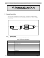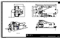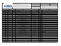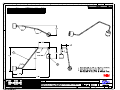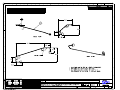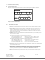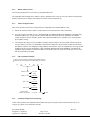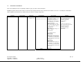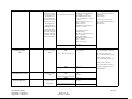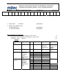
1
WRK-340420RX-485-ES-00
C-Band 1:1 Downlink Redundant Kit
with Bias Tee/Controller
Operation and Maintenance Manual
This page has been intentionally left blank.
mitec telecom inc.
Designers and manufacturers of telecom and wireless products
9000 Trans Canada,
Pointe-Claire, Quebec, Canada
H9R 5Z8
OPERATION AND MAINTENANCE MANUAL
Preliminary
Released
REVISION RECORD
Revision
ECN #
1
Description
Date
Preliminary Release.
CM Approval
Approved
01 Mar 07
TITLE:
C-Band 1:1 Downlink Redundant
System with Bias T/Controller
This document contains information proprietary to mitec telecom inc., or its affiliates, or to a third party to which mitec telecom inc. may have a legal obligation to protect
such information from unauthorized disclosure, use, or duplication. Any disclosure, use, or duplication of this document or of any of the information contained herein is
expressly prohibited except as mitec telecom inc. may otherwise agree in writing.
Designer: N. roy
Date: 01 Mar 07
Technical Writer: C. Strunga
Date: 01 Mar 07
REV 0
DOCUMENT NO.
213265-001MA
PAGE 1 OF 15
This page has been intentionally left blank.
mitec
C-Band 1:1 Downlink Redundant System with Bias T/Controller
Table of Contents
Table of Contents
1.1 General Description .................................................................................................1
1.1.1 Abbreviations ...................................................................................................1
1.2 Receiving and Inspection .........................................................................................2
1.2.1 Equipment Damage or Loss .............................................................................2
1.2.2 Return of Equipment ........................................................................................2
1.3 Preparing for Installation ........................................................................................3
1.3.1 Safety Precautions ............................................................................................3
2.1 Assembly of WRK-340420RX-485-ES-00 ..............................................................5
2.2 Operation ..................................................................................................................6
2.2.1 Downlink Redundant Kit Interface Connections .............................................6
2.3 Maintenance..............................................................................................................7
2.3.1 LNB Maintenance ............................................................................................7
2.3.2 Waveguide Switch Maintenance ......................................................................7
APPENDIX A .................................................................................. A-1
Drawings & Schematic Diagrams ............................................................................ A-1
APPENDIX B .................................................................................. B-1
LNB Documentation...................................................................................................B-1
APPENDIX C .................................................................................. C-1
Serial Protocol Documentation ................................................................................ C-1
APPENDIX D .................................................................................. D-1
Bench Test Record..................................................................................................... D-1
List of Tables
Table 1 – Abbreviations and Definitions.............................................................................1
Table 2: RF Ports and Control Interface..............................................................................6
Rev 0
P-1
This page has been intentionally left blank.
mitec
C-Band 1:1 Downlink Redundant System with Bias T/Controller
Preface
Preface
Scope
This document covers the installation of the C-Band 1:1 Downlink Redundant System with Bias
T/Controller. It contains information intended for engineers, technicians and operators working
with the redundant system.
To make inquiries, or to report errors of fact or omission in this document, please contact mitec
telecom inc at (514) 694-9000.
IMPORTANT
Important information concerning the operation and care of this product, as well as safety of
authorized operators is highlighted throughout this document by one of the following labels:
NOTE
Indicates a reminder, a special consideration, or additional
information that is important to know.
CAUTION!
Identifies situations that have the potential to cause equipment
damage.
WARNING!!
Identifies hazardous situations that have the potential to cause
equipment damage as well as serious personal injury.
Rev 0
P-1
This page has been intentionally left blank.
mitec
C-Band 1:1 Downlink Redundant System with Bias T/Controller
Introduction
1 Introduction
1.1
General Description
The 1:1 Downlink Redundant Kit is an outdoor System. It includes two C-Band to L-Band
Block-Downconverters (LNB), a Bias Tee, with integrated controller and a WR 229 waveguide
switch assembly.
Down Link System WRK-340420RX-485-ES-00
IF
24VDC
1
IF
24VDC
BIAS T
2890078--01
IF
24VDC
WR229
1
F-type
2
4
4
3
IF
24VDC
SWITCH
M&C
1.1.1
LNB - A
LNB - B
F-type
2
RF In
From OMT 1
3
WR229
Abbreviations
Table 1 lists the abbreviations that may appear within this manual.
Table 1 – Abbreviations and Definitions
Abbreviation
A
AC
BUC
ºC
dB
dBm
DC
GHz
IDU
IF
LNB
M&C
MHz
Rev 0
Description
Ampere
Alternating Current
Block Up Converter
Degrees Celsius
Decibel
Decibel referenced to mW
Direct Current
Gigahertz (106 cycles per second)
In Door Unit
Intermediate Frequency
Low Noise Block
Monitor and Control
Megahertz (103 cycles per second)
Page 1
mitec
C-Band 1:1 Downlink Redundant System with Bias T/Controller
Abbreviation
N/A
ODU
RF
V
W
W/G
1.2
Introduction
Description
Not Applicable
Out Door Unit
Radio Frequency
Volt
Watt
Wave Guide
Receiving and Inspection
The redundant kit will arrive in a standard shipping container. Immediately upon receipt of the
Redundant Kit, check the Bill of Lading against the actual equipment you have received. Inspect
the shipping container exterior for visible damage incurred during shipping.
Refer to the WRK-340420RX-485-ES-00 assembly drawing and parts list in Appendix A.
CAUTION!
Handle the redundancy kit with extreme care. Excessive shock may
damage the redundancy kit’s delicate internal components.
NOTE
Before unpacking the shipping container, move them near to the
site where it will be mounted.
Verify that all items have been received and undamaged during shipment. Verify that all items
are complete. If there are any omissions or evidence of improper packaging, please notify mitec
telecom inc. immediately.
1.2.1
Equipment Damage or Loss
mitec telecom inc. is not responsible for damage or loss of equipment during transit. For
further information, contact the responsible transport carrier.
When declaring equipment as damaged during transit, preserve the original shipping cartons to
facilitate inspection reporting.
1.2.2
Return of Equipment
When returning equipment to mitec for repair or replacement:
1. Identify, in writing, the condition of the equipment,
2. Refer to the sales order, Purchase Order and the date the equipment was received,
Notify mitec Sales Administration Department of the equipment condition and obtain a Return
Material Authorization (RMA) number and shipping instructions. mitec will pay for the cost of
shipping the product to the customer after the repairs are completed.
Rev 0
Page 2
mitec
C-Band 1:1 Downlink Redundant System with Bias T/Controller
Introduction
NOTE
Do not return any equipment without an RMA number. This is
important for prompt, efficient handling of the returned
equipment and of the associated complaint.
1.3
Preparing for Installation
Before attempting to install or use the WRK-340420RX-485-ES-00, we recommend that you first
familiarize yourself with the kit by reading through this manual. Understanding the operation of
the redundant kit will reduce the possibility of incorrect installation, thereby causing damage or
injury to yourself or others.
The redundant kit must be installed in accordance with the
conditions and recommendations contained in the following
sections.
When you are ready to begin your installation, use the information in Chapter 2 (Installation) as a
guide for making all the required electrical connections.
1.3.1
Safety Precautions
Carelessness or mishandling of the redundant kit may damage the unit causing serious injury to
yourself or others. Please adhere to the following:
WARNING!!
This unit is equipped with power cords and plugs. Do not
tamper with, or attempt to reconfigure, the cords or plugs
supplied with the unit, as this can:
♦ result in personal injury
♦ void the warranty
♦ cause damage to the units or related equipment
Rev 0
Page 3
This page has been intentionally left blank.
mitec
C-Band 1:1 Downlink Redundant System with Bias T/Controller
Installation
2 Installation
Use the information in this section as a guide to assemble and install the redundant kit. The
system is designed to function outdoors with the specified humidity up to 100% during operation.
However, installation should be carried out in dry conditions, free of salt spray or excessive
humidity. This will eliminate the possibility of moisture and other foreign substances from
entering the output waveguide flange.
NOTE
A gasket shall be used to seal each waveguide connection.
2.1
Assembly of WRK-340420RX-485-ES-00
CAUTION!
Only authorized technical personnel should perform the
Installation and proper electrical hookups of the redundant
system.
The parts list in Appendix A details the parts of the WRK-340420RX-485-ES-00. Hardware and
gaskets are included to complete the assembly. Refer to the assembly drawing in Appendix A for
further details.
With reference to the assembly drawing, WRK-340420RX-485-ES-00AD, in Appendix A,
complete the following steps, if required.
1. If not already assembled and as per the assembly drawing, in Appendix A, assemble the
waveguide switch sub-assembly, connecting the waveguide termination and waveguide
bends to the switch. Use the hardware and gaskets specified on the assembly drawing.
2. With reference to the assembly drawing in Appendix A, assemble the LNBs, to the
waveguide flanges. Use the hardware and gaskets specified in the assembly drawing.
3. Using the supplied hardware, assemble to the mounting plate, as per the assembly
drawing.
4. Attach the controller assembly to the mounting plate, as per the assembly drawing, using
the supplied hardware.
5. Assemble the U-bolt mounting kit to the mounting plate, as per the assembly drawing.
Rev 0
Page 5
mitec
C-Band 1:1 Downlink Redundant System with Bias T/Controller
Installation
6. Complete the connections between the customer downlink waveguide port and the switch
sub-assembly. Use gasket and hardware as specified.
2.2
Operation
The Downlink kit contains two C-Band to L-Band LNBs that are standard purchased components,
and the input WR229 redundancy switch. For LNB technical information, refer to the LNB
manufacturer user manual.
The monitoring and control for the WRK-340420RX-485-ES-00 is accomplished through the
RS485 interface of the Bias T/controller assembly located on the mounting plate.
2.2.1 Downlink Redundant Kit Interface Connections
Table 2 details the connections for the downlink redundant kit.
Table 2: RF Ports and Control Interface
Connector
Name
Type
Pin #
Signal Name
WR229
N/A
RF Output
WR229
N/A
RF Input
WR229
N/A
RF Output
WR229
N/A
N/A
N-type
N/A
IF Input
N-type
N/A
IF Output
N-type
N/A
IF Input
N-type
N/A
N/A
Switch
J1
MS3112E-14-15P
A
B
C
D
E
F
DRV_A
DRV_RTN
DRV_B
IND_A
IND_RTN
IND_B
Control Module
IF OUT
J1
N Type Female
IF out +24Vdc in
Control Module
IF IN
J2
N Type Female
IF in +24Vdc OUT
Switch
Port1
Switch
Port2
Switch
Port3
Switch
Port4
Switch
Port1
Switch
Port2
Switch
Port3
Switch
Port4
Rev 0
Description
RF Output
(to LNB-A)
RF Input
(from antenna)
RF Output
(to LNB-B)
Terminated
(50Ω Load)
IF Input
(from LNB-A)
IF Output
(to Modem)
IF Input
(from LNB-B)
Terminated
(50Ω Load)
Page 6
mitec
C-Band 1:1 Downlink Redundant System with Bias T/Controller
Connector
Name
2.3
Type
Control Module
User Interface
J3
MS3112E14-15P
SW Control
Module
J4
MS3112E-14-12S
Pin #
A
B
C
D
E
A
B
C
D
E
F
Installation
Signal Name
Description
+
TX
TX-
GND
RX+
RXDRV_A
DRV_RTN
DRV_B
IND_A
IND_RTN
IND_B
RS-485
Maintenance
WARNING!!
Shut down the LNBs before any maintenance is attempted.
Failure to do so will result in personal injury. This includes
removal of any RF power originating from other system
components.
The WRK-340420RX-485-ES-00 requires very little preventive maintenance or repair.
2.3.1 LNB Maintenance
For preventive maintenance of the LNBs, refer to the LNB User Manual.
2.3.2 Waveguide Switch Maintenance
Toggle the switching system at least once every three months to ensure proper switch operation.
Rev 0
Page 7
This page has been intentionally left blank.
mitec
C-Band 1:1 Downlink Redundant System with Bias T/Controller
Appendix A
Appendix A
Drawings & Schematic Diagrams
MD-WRK-340420RX-485-ES-00 - Model Outline Drawing
AD-WRK-340420RX-485-ES-00 - Assembly Drawing
BM-WRK-340420RX-485-ES-00 - Parts List
211915-001 - Cable Assembly
211916-001 - Cable Assembly
211917-001 - Cable Assembly
19972-001AD - Cable Assembly
WRK-340420RX-485-00WD - Wiring Diagram
A-1
Rev 0
This page has been intentionally left blank.
This page has been intentionally left blank.
This page has been intentionally left blank.
Mitec PART LIST
ECN HISTORY
DATE
REV
DESCRIPTION
09-Jun-06
20-Jun-06
0
1
FIRST RELEASE
ECN295-06S
S.ZHOU
G.FENG
15-Jul-06
2
ECN342-06S
G.FENG
ICI
Item no.
omponent Designatio
1
2
3
4
5
6
7
8
9
10
11
12
13
14
15
16
17
18
19
20
21
22
23
24
25
FORM 11520-001CFRev03
BM-WRK-340420RX-485-ES-00
CM Approval;
Value
SIGNATURES
C BAND DOWNLINK COLD REDUNDANT SYSTEM
ASSEMBLY
DATE
ORIGINATOR: GUOQING FENG
ENG: S.ZHOU / N.ROY
APPROVAL: MARINA LISSIANSKAIA
APPROVAL: MARINA LISSIANSKAIA
Description
2
Title
FIRST APPROVAL
BY;
3/7/2007
REV
Drawing/CADM Office No;
CADM Release Date
1.) MITEC SHALL APPROVE ALL ALTERNATE PARTS.
2.) CHANGES FROM PREVIOUS ISSUES. THE ICI COLUMN ON THIS DOCUMENT IS MARKED WITH AN "X" TO INDICATE
WHERE CHANGES (ADDITIONS, MODIFICATIONS, CORRECTIONS, DELETIONS) FROM THE PREVIOUS ISSUE WERE
MADE. THIS WAS DONE AS A CONVENIENCE ONLY, AND MITEC ASSUMES NO LIABILITY WHATSOEVER FOR ANY
INACCURACIES IN THESE NOTATIONS. BIDDERS AND CONTRACTORS ARE CAUTIONED TO EVALUATE THE
REQUIREMENTS OF THIS DOCUMENT BASED ON THE ENTIRE CONTENT, AS WRITTEN, IRRESPECTIVE OF THE ICI
NOTATION AND RELATIONSHIP TO THE LAST PREVIOUS ISSUE.3.)EXCEPT AS MAY BE OTHERWISE PROVIDED BY
CONTRACT,THESE DRAWINGS AND SPECIFICATIONS CONTAIN PROPRIETARY INFORMATION AND ARE THE PROPERTY
OF MITEC AND ARE ISSUED IN STRICT CONFIDENCE AND SHALL NOT BE TRANSMITTED, REPRODUCED, COPIED OR
USED AS THE BASIS FOR MANUFACTURE OR SALE OF APPARATUS WITHOUT PRIOR WRITTEN PERMISSION.
NEXT ASSY.
USED ON
09-Jun-06
09-Jun-06
09-Jun-06
15-Jul-06
Mitec Part No.
QTY
C BAND DOWNLINK COLD REDUNDANT SYSTEM
C BAND DOWNLK COLD REDUNDANT SYSTEM BENCH TEST RECORD
C BAND DOWNLINK COLD REDUNDANT SYSTEM CABLING DIAGRAM
AD-WRK-340420RX-485-ES-00
WRK-340420RX-485-ES-00TP
WRK-340420RX-485-ES-00WD
REF
REF
REF
ADAPTER COAX , F MALE TO N FEMALE
BASE BRACKET(ROHS)
BIAS TEE
C BAND PLL LNB F-FEMALE TYPE
CABLE ASSY, SEMI-RIGID COAX CABLE (ROHS)
CABLE ASSY, SEMI-RIGID COAX CABLE (ROHS)
CABLE ASSY, SEMI-RIGID COAX CABLE (ROHS)
COVER, CONNECTOR, ESD, SHELL #10
FULL GSKT RECTANGULAR O-RING FOR CPR 229
HALF GSKT RECTANGULAR O-RING FOR CPR 229
NUT 1/4-20UNC, HEX
RES TERMINATION
RF SWITCH CABLE ASSEMBLY
SCREW 1/4-20 x 0.625LG, HEX SOC HD CAP
SCREW 1/4-20 x 0.875LG, HEX SOC HD CAP
SCREW FLAT 82 DEG PHILLIPS 8-32L3/8
WASHER, #1/4, LOCK
WR 229 W/G ASSEMBLY
WR229 LOW POWER TERMINATION
WR229 W/G, TYPE N SW, SEALED, +12VDC, CKT4
CON CYL PWR 14 15 MS3116 S E 7.5
HARDWARE KIT WR229 CPRG
U-BOLT MOUNTING KIT
SCREW 1/4-20UNC x 1/2LG, CSINK FLAT PHILLIPS, SS
LOCKTITE 24231, BLUE
001-1221
211951-001
2890078-01
211915-001
211916-001
211917-001
100598-003
1511308-2
1511309-2
011-0254
5079013
19972-001AD
011-0231
011-0237
6212015-06
011-0260
210533-001
2523292-2-2
017-0203
4849044
211948-001PL
2840006-01
011-1018
020-0082
2
1
1
2
1
1
1
1
4
1
20
1
1
30
20
3
50
2
1
1
1
1
2
4
A/R
REV Comments and Alternate P/N
OPTION, NOT SHOWN
SHIPPING LOOSE
SHIPPING LOOSE
SHIPPING LOOSE
Page 1 of 1
A3/J3
A1/J2
Description
Item
Con cyl pwr 14 12 ms3116 pe7
Con cyl pwr 14 15 ms3116 pe7
Cable sheilded 10 lead 22 awg
Connector A1/J2
Connector A3/J3
Cable
Note 1: Connector drawings are for representation purpose only.
Note 2: 4849042 & 4849044 are ordered in the top level
Note 3: Install labels marked with the references on connectors as shown.
Note 4: Use shrink tubing to cover the end of the PVC at the point the
strength relieve of each connector is grabbing the cable. Shrink tubing
should not be sticking out of the connector for less than ½ inch or more
than 1 inch.
Item #
4849042
4849044
045-0005
Qty
1
1
20"
Note 5: DO NOT over tight the strength relieves on the connector.
Excessive pressure will damage the wire isolation.
Note 6: Identify the cable as per Mitec QPP-1050.
W ire List
Wire #
1
2
3
4
5
6
From
A1/J2 Pin
A1/J2 Pin
A1/J2 Pin
A1/J2 Pin
A1/J2 Pin
A1/J2 Pin
A
B
C
D
E
F
Termination
Strip
Strip
Strip
Strip
Strip
Strip
To
A3/J3 Pin
A3/J3 Pin
A3/J3 Pin
A3/J3 Pin
A3/J3 Pin
A3/J3 Pin
A
B
C
D
E
F
Termination
Strip
Strip
Strip
Strip
Strip
Strip
Colour
Black
Brown
Red
Orange
Yellow
Green
AWG
22
22
22
22
22
22
Length (inches)
+/- 1 inch
20"
20"
20"
20"
20"
20"
Signal
(A-B Port 1
GND
(C-B Port 1
(A-B Port 1
GND
(C-B Port 1
- 2)
- 4)
- 2)
- 4)
mitec
``
5
4
3
2
1
REVISION
Rev
DESCRIPTION
Date:
.
.
.
.
.
.
.
.
.
.
.
.
APP:
D
D
LNB A
A2
211916-001
J2
J1
N type IF Out
WR229 RF In
210533-001
C
System IF Out L Band,
+ 24V DC in
Buc/Current Senser
2890078-01
J1
C
RF Switch
J2
N type IF out
N Type Port1
211915-001
N type IF in
N Type Port2
N Term
A1
N Type Port4
N Type Port3
WR229 Port1
A3
System RF Input
WR229 Port2
WR229 Port4
RS ACCESS
(MS3112F14-19P)
WR229 Term
WR229 Port3
JS
A1/J1
J1
M&C ACCESS
(MS3112F14-15P)
RF Switch / Curent sensor
ACCESS (MS3112F14-12S)
19972-001AD
J4
A3/J3
User Interface
RS-485
A1/J2
210533-001
MS3116fF14-15S
B
B
211917-001
J1
J2
N type IF Out
WR229 RF In
A4
LNB B
CM approval
Title
This document is private and confidential and is supplied on the express condition
that it is not to be used for any other purpose or copied or reproduced in any form
or communicated to any other person without the written consent of :
mitec telecom inc.
A
C to L-BAND, DownLink
REDUNDANT SYSTEM
Date:
03-07-07
Originator:
N Roy
Cage ident. no.
38494
Date:
03-07-07
Designer:
N Roy
5
Project no. / Job no.
4
3
--
Next assy.
--
(FORM 11477-010CF REV 0)
2
A
Size
B
Document Number
WRK-340420RX-485-ES-00WD
Rev
0
Sheet
1
1
of
1
mitec
C-Band 1:1 Downlink Redundant System with Bias T/Controller
Appendix B
Appendix B
LNB Documentation
Appendix B contains the manufacturer documentation relevant to the LNBs if they are been
purchased with this redundant kit.
B-1
Rev 0
This page has been intentionally left blank.
mitec
C-Band 1:1 Downlink Redundant System with Bias T/Controller
Appendix C
Appendix C
Serial Protocol Documentation
Appendix C contains the serial protocol documentation relevant to this redundant kit.
C-1
Rev 0
This page has been intentionally left blank.
9000 Trans Canada, Pointe Claire, QC, Canada H9R 5Z8
Confidential and Proprietary to Mitec. This is a Controlled Document.
Document Name:
Protocol Specification
Revision:
0C
File Name:
PS-3900047-00-R0C
Page:
Page 1 of 14
Model Number:
N/A
Originator:
C. Villeneuve
Revision
0A
Date
07-Oct-2003
0B
02-Feb-2004
0C
1-Apr-2004
Change Summary
Protocol specifications for down-link redundant kit WRK109128RX-485-ES-00.
Completely revamped the document format. No functional
changes made to the software itself
Examples redone with control module -= 0x1. (ECN8804S)
Approval
C. Villeneuve
C. Villeneuve
C. Villeneuve
Serial Communication Protocol Specification
For
Down-Link Redundant Kit
Software Version 3900047-00
Table of Contents
1
Document legend _______________________________________________________________ 3
2
Project Overview _______________________________________________________________ 3
3
Definitions and acronyms _________________________________________________________ 3
4
Scope _______________________________________________________________________ 3
5
Serial Communications Link Interface ________________________________________________ 4
6
5.1
Customer Interface Port Configuration _____________________________________________4
5.2
Customer Interface Transport Medium _____________________________________________4
5.3
Customer Interface Cable Connections ______________________________________________4
Communication Protocol Framing ___________________________________________________ 6
6.1
6.1.1
6.1.2
6.1.3
6.1.4
6.1.5
7
8
SCI Packet Frame Format ________________________________________________________6
SCI Packet Byte Description ___________________________________________________________
Default Address Values _______________________________________________________________
Address Setup Procedure______________________________________________________________
CRC Calculation Example_____________________________________________________________
Command / Reply Packet Sequencing____________________________________________________
6
7
7
1
7
Command List _________________________________________________________________ 8
7.1
Default Reply Packet Format ______________________________________________________8
7.2
GET Status Command List________________________________________________________9
7.3
GET Alarms Command List______________________________________________________12
7.4
SET Control Command List______________________________________________________13
Appendix I: Troubleshooting Guide _________________________________________________ 14
PS-3900047-00-R0C
Designed: C. Villeneuve
Approved: C. Villeneuve
Rev. 0C
Page 2 of 14
05-03-07 8:58 AM
1
Document legend
Text in this document highlighted in grey identifies features which are planned but not implemented yet.
2
Project Overview
This document describes the communications protocol used to communicate with down-link redundant kit configured
with control software 3900047-00.
The system as a whole consists of 1 main unit which the user may communicate with: The redundant control module.
Refer to Figure 1) System Block Diagram.
Customer PC / Modem
Customer
Interface
Downlink Control
Module
(ex. Address = 0xF)
Figure 1) System Block Diagram
3
Definitions and acronyms
The following terms appear throughout this document:
BUC:
CM:
Controller:
CRC:
Customer Interface Port:
Customer Interface Device:
LNB:
PC:
RF:
SCI:
WBT:
WTX:
4
Block Up Converter
Control Module.
The microprocessor-based card and associated embedded software which
handles all communications between the customer interface and the
amplifier.
Cyclic Redundancy Check
The interface port through which the device used by the customer will
interact with the Transceiver (ie. typically a modem or PC).
The interface device used by the customer to interact with the Transceiver
(ie. typically a modem or PC).
Low Noise Block
Personal Computer.
Radio Frequency.
Serial Communications Interface.
Wavesat Bias Tee Unit
Wavesat Transmitter. Also referred to as ODU or Booster.
Scope
This document covers all aspects of the communication protocol which are required for the customer to develop a
controlling device (typically a PC application program or modem) to interface with the Mitec product.
PS-3900047-00-R0C
Designed: C. Villeneuve
Approved: C. Villeneuve
Rev. 0C
Page 3 of 14
05-03-07 8:58 AM
5
5.1
Serial Communications Link Interface
Customer Interface Port Configuration
The customer interface port of the controller is configured as follows:
Baud Rate:
19200bps
Data bits:
8
Stop bits:
1
Parity:
None
HW Control
None
5.2
Customer Interface Transport Medium
The customer interface transport medium for this product may be configured for RS232, RS485 half duplex and
RS485 full duplex during production of the system. As a result, the customer must refer to the product user
manual to confirm the interface of the product purchased.
5.3
Customer Interface Cable Connections
This software protocol remains the same regardless of the transport medium used (ie RS232, RS485 half duplex
or RS485 full duplex). This section defines the wiring required to communicate with the Mitec product.
Note that the pin numbers on both side of the cable are deliberately omitted since these will vary depending on
the Mitec product as well as the PC / Modem interface. Please refer to the specific user manuals for pin
allocations.
For RS232:
PC / Modem
Interface
TX
RX
RX
TX
Gnd
Gnd
Customer
Interface
Note: Some PC com ports require that loopbacks be present at the PC / modem interface. If
such is the case, then connect the following signals together at the PC / modem interface:
Interconnect: "DTE Ready" to "DCE Ready" to "Received Line Signal Detect".
Also interconnect: "Request to Send" to "Clear to Send"
Also note that this diagram only represents the serial communication connections. Refer to
the user manual for any other signals which may be provided through this interface.
Figure 2) RS232 Customer Interface Wiring
PS-3900047-00-R0C
Designed: C. Villeneuve
Approved: C. Villeneuve
Rev. 0C
Page 4 of 14
05-03-07 8:58 AM
For RS485 Half Duplex:
Data+
TX+
RX+
PC / Modem
Interface
TX-
Data-
Customer
Interface
RXGnd
Gnd
Note: Some PC cards provide TX+, RX+, TX- and RX- hardware signals
instead of Data+ and Data-. In this case, the TX+ and RX+ lines are to be
shorted together to form the Data+ signal. Similarly, the TX- and RX- lines
are to be shorted together to form the Data- signal.
Also note that this diagram only represents the serial communication
connections. Refer to the user manual for any other signals which may be
provided through this interface.
Figure 3) RS485 Half Duplex Customer Interface Wiring
For RS485 Full Duplex (ie RS422):
PC / Modem
Interface
RX+
TX+
TX+
RX+
RX-
TX-
TX-
RX-
Gnd
Gnd
Customer
Interface
Note that this diagram only represents the serial communication
connections. Refer to the user manual for any other signals which may be
provided through this interface.
Figure 4) RS485 Full Duplex (ie RS422) Customer Interface Wiring
PS-3900047-00-R0C
Designed: C. Villeneuve
Approved: C. Villeneuve
Rev. 0C
Page 5 of 14
05-03-07 8:58 AM
6
6.1
Communication Protocol Framing
SCI Packet Frame Format
The packets exchanged with the master controller will have the following format (regardless of direction):
Packet Frame Format:
MSB
STX
LSB
Dest/Src
Address
Cmd/Len
Data
CRC
MSB
Data Format:
Data1
ETX
LSB
Data2
Datan-1
Datan
Figure 5) SCI Packet Frame Format
6.1.1
SCI Packet Byte Description
♦
STX is the start transmission byte (defined as 0x7E). This byte is used to determine the start of a packet.
♦
Dest/Src Address contains the destination address in the high nibble and the source address in the low
nibble. The destination address is the address of the device which is to process the packet. The source
address is the address of the device which sent the packet. Note that the device address of the customer
interface device is always = 0x0F.
♦
CMD/Len contains the packet command in the high nibble and the number of bytes in the data portion of
the packet in the lower nibble.
The following commands may be sent by the customer interface device:
GET (command high nibble = 0x0)
Request the current value of a database element.
SET (command high nibble = 0x1)
Set the database element to the specified value.
The following commands may be returned to the customer interface device:
UPD (command high nibble = 0x8)
Return the current value of a database element.
ACK (command high nibble = 0xE)
Acknowledge a received packet.
NACK (command high nibble = 0xF)
Reject a received packet (Not ACKnowledge).
♦
Data1 - Datan contains the packet payload. The value of the data bytes is specific to the command and will
be covered in following sections.
♦
CRC is the cyclic redundancy check and is calculated by performing a byte-wise exclusive OR of the
Dest/Src address byte, Cmd/Len byte and all data bytes. A bit-wise inversion is then applied to the CRC
before being inserted into the packet. Refer to 0Error! Not a valid bookmark self-reference.
♦
ETX is the end transmission byte (defined as 0x7F). This byte is used to determine the end of a packet.
PS-3900047-00-R0C
Designed: C. Villeneuve
Approved: C. Villeneuve
Rev. 0C
Page 6 of 14
05-03-07 8:58 AM
6.1.2
Default Address Values
The customer interface device must always be assigned address 0xF.
The redundant control module device address is factory defaulted to 0xF. It may be set by the customer using the SET
Master Controller Device Address command (refer to SET Control Command List).
6.1.3
Address Setup Procedure
This section provides instructions to confirm the preset redundant control module address of 0xF.
1) Ensure the customer interface cable is wired as shown in Customer Interface Cable Connections.
2) Use a PC program or modem to issue a “GET MASTER CONTROLLER DEVICE ADDRESS” command using
destination address 0xF. A reply from the controller indicates that the link has been established. Note that the
control module will always respond to packets with a destination address 0xF, regardless of it’s current internal
device address setting.
3) The customer may choose to leave the address at address 0xF provided it is the only module connected to the PC
com port. If there is at least a second module connected (for example, the up link control module), then the down
link address will have to be changed to a unique address other than 0xF. This is accomplished by removing all other
modules from the com port and sending a “SET CONTROL MODULE DEVICE ADDRESS” command to the
redundant control module to set the device address to the desired value (say 0x02). If an ACK reply was received,
then the command was accepted
6.1.4
CRC Calculation Example
To send a command to read the redundant status (database element =
0xFF08) from the control module (device address 0x0F), the command
is:
7E
FF
02
FF
08
Dest/Src = 0xFF
1111 1111
CMD/Len = 0x02
0000 0010
F5
7F
XOR
= 1111 1101
XOR
Data1 = 0xFF
1111 1111
= 0000 0010
XOR
Data2 = 0x08
0000 1000
= 0000 1010
Perform bitwise
inversion of final result:
6.1.5
= 1111 0101
= 0xF5
CRC
Command / Reply Packet Sequencing
Under normal operation, the redundant control module will only send a packet to the customer interface device in
response to a packet received from the customer.
PS-3900047-00-R0C
Designed: C. Villeneuve
Approved: C. Villeneuve
Rev. 0C
Page 7 of 14
05-03-07 8:58 AM
7
7.1
Command List
Default Reply Packet Format
This section identifies the packet format the ACK (Acknowledge) and NACK (Not acknowledge) replies which may be sent to the customer interface device in
response to a received command.
NOTE: The packets shown in the list below are based on the assumption that the master controller device address is set to 0x1. To modify the commands for
different addresses, the Dest/Src byte and the CRC byte will have to change in all packets.
Reply
ACK (Acknowledge)
Packet Format
7E FX E0 ZZ 7F
Explanation
Acknowledge that the received packet was
properly processed.
NACK (Not Acknowledge)
7E FX F1 YY ZZ 7F
Indicate that a problem was encountered with
the received packet.
Interpretation
X = Device address of the packet
source device.
ZZ = CRC.
X = Device address of the packet
source device.
Examples
1) reply: 7E F1 E0 EE 7F
(ACK reply sent from the redundant control
module)
1) reply: 7E F1 F1 03 FC 7F
(NACK reply sent from the redundant control
module for an invalid CRC)
YY = Error code
(03 = Incorrect CRC
18 = Unrecognized command
30 = Set command attempted on a
restricted database element)
ZZ = CRC.
PS-3900047-00-R0C
Designed: C. Villeneuve
Approved: C. Villeneuve
Rev. 0C
Page 8 of 14
05-03-07 8:58 AM
7.2
GET Status Command List
This section identifies the list of commands available to query any unit for status information.
NOTE: The packets shown in the list below are based on the assumption that the master controller device address is set to 0x1. To modify the commands for
different addresses, the Dest/Src byte and the CRC byte will have to change in all packets.
Command
Get Redundant Status
Packet Format
7E 1F 02 FF 08 15 7F
Explanation
Query control module
for redundancy status
Possible Replies
Update Redundant Status:
7E F0 84 FF 08 XX YY ZZ 7F
Interpretation
XX = Bitmap as follows:
Bit 0: Protection fault alarm status
(0 = no alarm; 1 = alarm)
Bits 2,1: RF switch position (00 =
undetermined; 01 = side A active;
10 = side B active; 11 = switch in
between 2 positions)
Bits 4,3: RF switch force setting
(00 = no force applied; 01 = forced
to side A; 10 = forced to side B; 11
= not applicable)
Bit 5: Not Used
Bit 6: 10MHz alarm setting (0 = no
alarm; 1 = alarm)
Bit 7: Not used
Examples
1) cmd: 7E 1F 02 FF 08 15 7F
reply: 7E F1 84 FF 08 04 00 79 7F
(No protection fault alarm;
RF switch on position B;
No force applied;
No alarms)
2) cmd: 7E 1F 02 FF 08 15 7F
reply: 7E F1 84 FF 08 0A 0C 7B 7F
(No protection fault alarm;
RF switch on position A;
Forced applied to side A;
LNB A alarm)
YY = Bitmap as follows:
Bit 0: Not used
Bit 1: Not used
Bits 3,2: LNB A alarm status (00 =
not applicable; 01 = undetermined;
10 = applicable / no alarm (LNB A
OK); 11 = applicable / alarm (LNB
A in alarm))
Bit 4: Not used
Bit 5: Not used
Bits 7,6: LNB B alarm status (00 =
not applicable; 01 = undetermined;
10 = applicable / no alarm (LNB B
OK); 11 = applicable / alarm (LNB
B in alarm))
NACK
PS-3900047-00-R0C
Designed: C. Villeneuve
Approved: C. Villeneuve
ZZ = CRC.
Refer to 7.1.
Rev. 0C
Page 9 of 14
05-03-07 8:58 AM
Command
Get Alarm Log
Packet Format
7E 1F 02 20 FF 3D 7F
Explanation
Query the control
module for the alarm
log status. The alarm
log identifies if an
alarm condition has
occurred since the last
time the log was reset.
Possible Replies
Update Alarm Log:
7E F1 84 20 FF XX YY ZZ 7F
Note that the Get
Redundant Status
command provides the
current state of the
alarms (other than the
BUC alarms which are
latched), whereas this
command retains the
history of the alarms.
7E 1F 02 05 FC 1B 7F
Query Control Module
for SW version base
MSB
Examples
1) cmd: 7E 1F 02 20 FF 3D 7F
reply: 7E F1 84 20 FF 84 00 D1 7F
(24Vdc alarm;
Summary alarm)
2) cmd: 7E 1F 02 20 FF 3D 7F
reply: 7E F1 84 20 FF 80 02 D7 7F
(BUC A alarm;
Summary alarm)
YY = Bitmap as follows:
Bit 0: Not Used
Bit 1: BUC A alarm status (0 = no
alarm; 1 = alarm)
Bit s2 - 4: Not Used
Bit 5: BUC B alarm status (0 = no
alarm; 1 = alarm)
Bits 6 - 7: Not Used
NACK
Get Control Module SW
Version Base number
(MSB)
Interpretation
XX = Bitmap as follows:
Bit 0: protection fault alarm status
(0 = no alarm; 1 = alarm)
Bit 1: 10MHz reference alarm
status – if applicable (0 = no alarm;
1 = alarm)
Bit 2: 24Vdc alarm status (0 = no
alarm; 1 = alarm)
Bit 3-6: Not Used
Bit 7: Summary alarm status (0 =
no alarm; 1 = alarm)
Update SW Version Base
MSB:
ZZ = CRC.
Refer to 7.1.
SW version base number MSB is
always 0x3900.
7E F1 84 05 FC 39 00 4A 7F
1) cmd: 7E 1F 02 05 FC 1B 7F
reply: 7E F1 84 05 FC 39 00 4A 7F
cmd: 7E 1F 02 05 FD 1A 7F
reply: 7E F1 84 05 FD 00 47 35 7F
cmd: 7E 1F 02 05 FE 19 7F
reply: 7E F1 84 05 FE 00 00 71 7F
cmd: 7E 1F 02 05 FF 18 7F
reply: 7E F1 84 05 FF 30 41 01 7F
NACK
Get Control Module SW
Version Base number (LSB)
Get Control Module SW
Version Configuration
PS-3900047-00-R0C
Designed: C. Villeneuve
Approved: C. Villeneuve
7E 1F 02 05 FD 1A 7F
7E 1F 02 05 FE 19 7F
Query Control Module
for SW version base
LSB
Query Control Module
for SW version
configuration
Update SW Version Base
LSB:
7E F1 84 05 FD XX XX ZZ 7F
NACK
Update SW Version Config:
7E F1 84 05 FE 00 XX ZZ 7F
NACK
Refer to 7.1.
The resulting software version is:
3900047-00-R0A
XX XX = SW version base number
(LSB).
ZZ = CRC.
Refer to 7.1.
XX = SW version configuration.
ZZ = CRC.
Refer to 7.1.
Rev. 0C
Page 10 of 14
05-03-07 8:58 AM
Command
Get Control Module SW
Version Revision
Get Control Module Device
Address
Packet Format
7E 1F 02 05 FF 18 7F
7E FF 02 03 06 07 7F
Explanation
Query Control Module
for SW version
revision
Query Control Module
for device address
Possible Replies
Update SW Version revision:
7E F1 84 05 FF RR RR ZZ 7F
NACK
Update control module
device address:
7E FF 84 03 06 00 XX ZZ 7F
NACK
PS-3900047-00-R0C
Designed: C. Villeneuve
Approved: C. Villeneuve
Interpretation
RR RR = SW version revision
represented as two ASCII
characters.
ZZ = CRC.
Refer to 7.1.
XX = Control module device
address.
ZZ = CRC.
Refer to 7.1.
Examples
1) cmd: 7E FF 02 03 06 E7 7F
reply: 7E FF84 03 06 00 0F 8E 7F
(Control module device address =
0xF)
2) cmd: 7E FF 02 03 06 E7 7F
reply: 7E FF 84 03 06 00 00 81 7F
(Control module device address =
0x0)
Rev. 0C
Page 11 of 14
05-03-07 8:58 AM
7.3
GET Alarms Command List
This section identifies the list of commands available to query any unit for alarm information.
All alarms are available as bits in the Get Redundant Status command.
PS-3900047-00-R0C
Designed: C. Villeneuve
Approved: C. Villeneuve
Rev. 0C
Page 12 of 14
05-03-07 8:58 AM
7.4
SET Control Command List
This section identifies the list of commands available to set control parameters any unit.
NOTE: The packets shown in the list below are based on the assumption that the master controller device address is set to 0x1. To modify the commands for
different addresses, the Dest/Src byte and the CRC byte will have to change in all packets.
Command
Packet Format
Explanation
Toggle RF Switch
7E 1F 14 06 0A 00 00 F8 7F
Alternate the position of the RF switch. Note that
the packet will not be processed if the standby unit
is in alarm or if the RF switch is forced.
Force RF switch
7E 1F 14 19 FF 00 XX ZZ 7F
Force the RF switch to the specified side,
regardless of system conditions on that side.
XX = 0x00: Remove all forces
XX = 0x01: Force to side A
XX = 0x02: Force to side B
Alarm Reset
7E 1F 14 06 0B 00 XX ZZ 7F
ZZ = CRC
Reset the latched alarms on side A and/or B. Note:
This command does not clear the alarm log values.
XX = 0x01: Reset side A alarms only
XX = 0x10: Reset side B alarms only
XX = 0x11: Reset side A and side B alarms
Clear Alarm Log
Set Control Module Device
Address
PS-3900047-00-R0C
Designed: C. Villeneuve
Approved: C. Villeneuve
7E 1F 14 20 FF 00 00 2B 7F
7E FF 14 03 06 00 XX ZZ 7F
ZZ = CRC
Reset the logged alarms.
Set control module device address
((0 ≤ address ≤ 0xD) OR (address = 0xF))
Possible
Replies
ACK
Interpretation
Examples
Refer to 7.1.
NACK
Refer to 7.1.
ACK
Refer to 7.1.
1) cmd: 7E 1F 14 19 FF 00 01 13 7F
reply: ACK (Force to side A)
NACK
Refer to 7.1.
2) cmd: 7E 1F 14 19 FF 00 02 10 7F
reply: ACK (Force to side B)
ACK
Refer to 7.1.
3) cmd: 7E 1F 14 19 FF 00 00 12 7F
reply: ACK (Remove all forces)
1) cmd: 7E 1F 14 06 0B 00 10 E9 7F
reply: ACK
(Clear all latched alarms on side B only)
NACK
Refer to 7.1.
ACK
Refer to 7.1.
NACK
Refer to 7.1.
ACK
Refer to 7.1.
1) cmd: 7E FF 14 03 06 00 0F 1E 7F
reply: ACK
(Set control module device address to 0xF)
NACK
Refer to 7.1.
2) cmd: 7E FF 14 03 06 00 00 11 7F
reply: ACK
(Set control module device address to 0x0)
1) cmd: 7E 1F 14 06 0A 00 00 F8 7F
reply: ACK
2) cmd: 7E 1F 14 06 0B 00 11 E8 7F
reply: ACK
(Clear all latched alarms on both sides)
1) cmd: 7E 1F 14 20 FF 00 00 2B 7F
reply: ACK
(Clear the alarm log)
Rev. 0C
Page 13 of 14
05-03-07 8:58 AM
8
Appendix I: Troubleshooting Guide
Problem
No response at all from the redundant control module.
Reply packet is incomplete.
PS-3900047-00-R0C
Designed: C. Villeneuve
Approved: C. Villeneuve
Possible Remedies
1)
Ensure the cable assembly is wired properly (refer to 5.3Customer Interface Cable
Connections) and that it is properly connected between the control module customer interface
port and the customer device.
2)
Verify that the com port parameters are as specified in 5.1Customer Interface Port
Configuration.
3)
Confirm that the customer interface cable is connected to the correct PC com port.
4)
Ensure that there are no other applications executing on the same com port.
5)
If the transport medium is RS232, then connect the loopbacks identified in the note in Figure
2) RS232 Customer Interface Wiring.
6)
If using a control module address other than 0xF, then send a “GET Control Module Device
Address” command to destination address 0xF. The reply will contain the current control
module address. Note that the control module will respond to all commands received with
destination address 0xF.
7)
If the transport medium is RS485 half duplex, note that some PC cards require software
control of the RS485 transmit and receive buffer enable lines. The software in the customer
device may need to coordinate the enabling /disabling of these buffers.
8)
1)
Ensure the control module is powered on.
If software control of the transmit and receive buffer enable lines is required (RS485 half
duplex), then it is possible that the timing between the transition needs to be adjusted.
Rev. 0C
Page 14 of 14
05-03-07 8:58 AM
mitec
C-Band 1:1 Downlink Redundant System with Bias T/Controller
Appendix D
Appendix D
Bench Test Record
Appendix D contains the bench test record relevant to this redundant kit.
D-1
Rev 0
This page has been intentionally left blank.
ECN 059-07V PENDING
9000 Trans-Canada, Pointe Claire, PQ, T: 514-694-9000, F: 514-694-7652
Confidential and Proprietary to Mitec. This is a Controlled Document.
Document:
Number:
Rev:
Title:
Revision
0A
BR-WTX-14014546-70-ES-37-R0A
WTX-14014546-70-ES-37
0A
L-Ku-Band 40W 70 dB Gain ODU
Date
Sep/29/04
1
2.
Sep/29/04
1 of 3
Simon Zhou
Marina Lissianskaia
Change Summary
Engineering Release
Serial Number: _______________
Spec
Date:
Page:
Originator:
Approval
Parameters
Input Frequency, MHz
950-1450
Output Frequency, GHz
13.75-14.25
Gain, dB - 69dB typ
@ -40°C ambient
@ +25°C ambient
Approval
ML
Tested by: _______________
Date: _______________
F1
F2
F3
F4
F5
F6
950
1050
1150
1250
1350
1450
@ +55°C ambient
3
Gain flatness - +/-2.5dB nom
@-40°C ambient
@+25°c ambient
@+55°c ambient
4
Output Power @ P1dB, dBm
46.0 dBm, min
@-40°c ambient
46.0 dBm, min
@ +25°C ambient
46.0dBm, typ.
@ +55°C ambient
5
IMD, dBc – 30dBc typ
separated 5Mhz, 2 tones
@ 37dBm/tone
@ +25°C ambient
6
Spurious in Band, dBc
-50dBc max @P1dB
@-40°C ambient;
F out=13.75GHz
Fout=14.00GHz
Fout=14.25GHz
9000 Trans-Canada, Pointe Claire, PQ, T: 514-694-9000, F: 514-694-7652
Confidential and Proprietary to Mitec. This is a Controlled Document.
Document:
7
BR-WTX-14014546-70-ES-37-R0A
Revision: 0A
Page: 2 of 3
Spurious out of Band, dBc
-50dBc max @P1dB
@-40°C ambient;
Spec
Parameters
8
Phase Noise,
@ offset from Fc
-60dBc/Hz @ 300Hz
-70dBc/Hz @ 1KHz
-80dBc/Hz @ 10KHz
-90dBc/Hz @ 100KHz
-100dBc/Hz @ 1MHz
2.2 degrees max
from 300Hz up to 1MHz
9
Fc=14.25GHz
dBc/Hz @ 300Hz
dBc/Hz @ 1KHz
dBc/Hz @ 10KHz
dBc/Hz @ 100KHz
dBc/Hz @ 1MHz
degrees max
from 300Hz up to 1MHz
Temperature Shut Down
T ambient, °C +60°C min
T hot spot, °C +87°C max
Monitor and Control Interface Test.
1. Mute Control
via RS-485
2. Temperature monitor
Ambient T,°C
Passed/Failed
-40°C
+25°C
+55°C
Vtem.senc, V
3. Output Power Detector
3.1. Fout=13.75GHz
Pout, dBm
24
27
30
33
35
37
39
41
42
43
44
45
45.5
46
46.5
47
33
35
37
39
41
42
43
44
45
45.5
46
46.5
47
33
35
37
39
41
42
43
44
45
45.5
46
46.5
47
Vdet, V
3.2. Fout=14.00 GHz
Pout, dBm
24
27
30
Vdet, V
3.3 Fout=14.25 GHz
Pout, dBm
24
27
30
9000 Trans-Canada, Pointe Claire, PQ, T: 514-694-9000, F: 514-694-7652
Confidential and Proprietary to Mitec. This is a Controlled Document.
Document:
BR-WTX-14014546-70-ES-37-R0A
Revision: 0A
Page: 3 of 3
Vdet, V
4. System Alarm
via RS-485
passed/failed
5. System Alarm (Hardware line)
TTL high operational;
TTL low alarm condition
passed/failed
passed/failed
Plots and Graphs to be attached:
Test Item 2 - Gain vs Frequency @-40°C, +25°C, +55°C
Test Item 4 – Pin vs Pout at F1, F3, F6 @-40°C, +25°C, +55°C
Test Item 5 – IMD
@+25°C
Interface
___p.
___p.
___p.
Connector
Name
J1 “IF IN”
Type
Pin #
Signal Name
Description
Parameter
N-type female
N/A
IF In
IF Input
24 VDC IN
10 MHz Ref. In
J2 “RF OUT”
WR75G
N/A
RF Out
RF Output
3 “AC POWER
IN”
17pin
Bulkhead
Connector
(male)
MS3102R2029P
17pin
Bulkhead
Connector
(female)
MS3102R2029S
A
B
C
D-T
L (AC)
GND
N (AC)
-
Line
Ground
Neutral
Not Connected
-20 dBm, max
24 VDC, 1.0 A
-5dBm to
5dBm
47.0 dBm,
max
110/220 VAC
A
B
C
D
E
F
G
H-T
Rx+
RxTx+
TxDet
Alarm
GND
-
Rx+
RxTx+
TxDetector
Summary Alarm
GND
Not Connected
J4 “M&C”
Interface
RS-485
analog
TTL