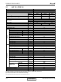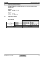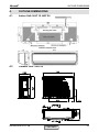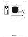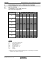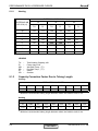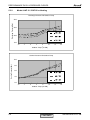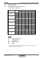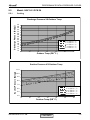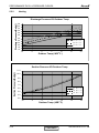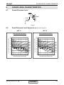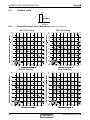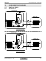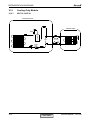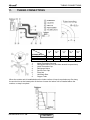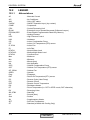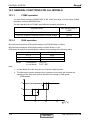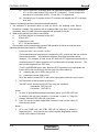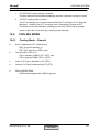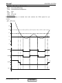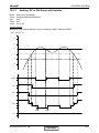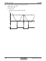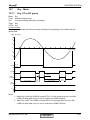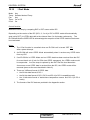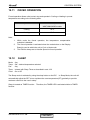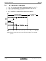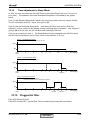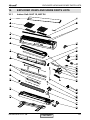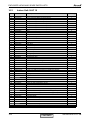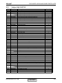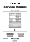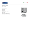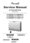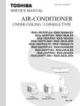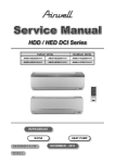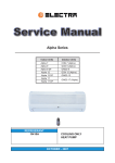
1
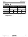
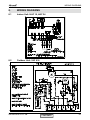
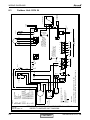
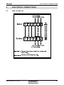
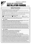
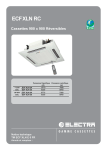
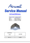
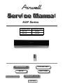
Service Manual
HAF Series
Indoor Units
Outdoor Units
HAF 18
YAF018
HAF 24
GCN 24
REFRIGERANT
COOLING ONLY
R410A
HEAT PUMP
SM HAFRPM 2-A.1 GB
FEBRUARY - 2010
CONTENTS
LIST OF EFFECTIVE PAGES
LIST OF EFFECTIVE PAGES
Note: Changes in the pages are indicated by a “Revision#” in the footer of each effected page
(when none indicates no changes in the relevant page). All pages in the following list represent
effected/ non effected pages divided by chapters.
Dates of issue for original and changed pages are:
Original ....... 0 ........ February 2009
Total number of pages in this publication is 72 consisting of the following:
Page
No.
Revision
No. #
Page
No.
Revision
No. #
Page
No.
Revision
No. #
Title ....................... 1
A ........................... 1
i ............................. 1
1-1 - 1-2 ................ 1
2-1 - 2-2 ................ 1
3-1 ........................ 1
4-1 - 4-2 ................ 1
5-1 - 5-12 .............. 1
6-1 - 6-2 ................ 1
7-1 ........................ 1
8-1 - 8-2 ................ 1
9-1 ........................ 1
10-1-10-2 .............. 1
11-1 ....................... 1
12-1-12-30 ............ 1
13-1-13-2 .............. 1
14-1-14-7 .............. 1
Appendix -A ...........1
• Zero in this column indicates an original page.
*Due to constant improvements please note that the data on this service manual can be modified with out notice.
**Photos are not contractual
A
CONTENTS
SM HAFRPM 2-A.1 GB
TABLE OF CONTENTS
Table of Contents
1.
INTRODUCTION ...................................................................................................1-1
2.
PRODUCT DATA SHEET ......................................................................................2-1
3.
RATING CONDITIONS ..........................................................................................3-1
4.
OUTLINE DIMENSIONS .......................................................................................4-1
5.
PERFORMANCE DATA & PRESSURE CURVES ................................................5-1
6.
SOUND LEVEL CHARACTERISTICS ..................................................................6-1
7.
ELECTRICAL DATA ..............................................................................................7-1
8.
WIRING DIAGRAMS .............................................................................................8-1
9.
ELECTRICAL CONNECTIONS .............................................................................9-1
10. REFRIGERATION DIAGRAMS .............................................................................10-1
11.
TUBING CONNECTIONS......................................................................................11-1
12. CONTROL SYSTEM .............................................................................................12-1
13. TROUBLESHOOTING ..........................................................................................13-1
14. EXPLODED VIEWS AND SPARE PARTS LISTS .................................................14-1
15. APPENDIX A .........................................................................................................15-1
SM HAFRPM 2-A.1 GB
i
INTRODUCTION
1.
INTRODUCTION
1.1
General
The new HAF series is split wall mounted type indoor unit.
It has innovative flat design with background display.
The models as below:
HAF 18
HAF 24
1.2
Main Features
The HAF series benefits from the most advanced technological innovations, namely:
● R410A refrigerant
● Micro processor control.
● Innovative flat panel.
● Background display.
● Fresh air system as an option.
● Refrigerant pipes can be connected to the indoor unit from 4 different optional
directions.
● Easy installation and service.
1.3
Indoor Unit
The indoor unit is wall mounted, and can be easily fitted to many types of residential and
commercials applications.
It includes:
● Casing with air inlet and outlet grills.
● A large-diameter tangential fan.
● Bended coil with treated aluminum fins.
● Advanced electronic control box assembly.
● Interconnecting wiring terminal block.
● Mounting plate.
1.4
Control
The microprocessor indoor controller, and an infrared remote control, supplied as
standard, provide complete operating function and programming. For further details
please refer to the Operation Manual, Appendix A.
SM HAFRPM 2-A.1 GB
CONTENTS
1-1
INTRODUCTION
1.5
Outdoor Unit
The HAF outdoor units can be installed as floor or wall mounted units by using a wall
supporting bracket. The metal sheets are protected by anti- corrosion paint work allowing
long life resistance. All outdoor units are pre-charged. For further information please
refer to the Product Data Sheet, Chapter 2.
It includes :
● Compressor mounted in a soundproofed compartment.
● Axial fan.
● Outdoor coil with hydrophilic louver fins for RC units.
● Outlet air fan grill.
● Service valves ” flare” type connection.
● Interconnecting wiring terminal block.
● Fresh air motor for HAF(optional).
1.6
Tubing Connections
Flare type interconnecting tubing can be produced on site.
For further details please refer to the Installation Manual, Appendix A.
1.7
Accessories
Remote Control
1.8
Inbox Documentation
Each unit is supplied with its own installation and operation manuals.
1.9
Matching Table
INDOOR UNIT
OUTDOOR UNITS
OUTLINE
1-2
MODEL
REFRIGER.
HAF 18
YAF018
R410A
√
GCN 24
R410A
CONTENTS
HAF 24
√
SM HAFRPM 2-A.1 GB
PRODUCT DATA SHEET
2.
PRODUCT DATA SHEET
2.1
HAF 18 | YAF018
Model Indoor Unit
Model Outdoor Unit
Installation Method of Pipe
Characteristics
Capacity (4)
Power input (4)
EER (Cooling) or COP(Heating) (4)
Energy efficiency class
Power supply
OUTDOOR
INDOOR
Rated current
Power factor
Prated (IDU)
Prated (IDU+ODU)
Starting current
Circuit breaker rating
Fan type & quantity
Fan speeds
H/M/L
H/M/L
Air flow (1)
External static pressure
Min
H/M/L
Sound power level (2)
H/M/L
Sound pressure level (3)
Moisture removal
Condenstate drain tube I.D
Dimensions
WxHxD
Net Weight
Package dimensions
WxHxD
Packaged weight
Units per pallet
Stacking height
Refrigerant control
Compressor type,model
Fan type & quantity
Fan speeds
H
Air flow
H
Sound power level
H
H
Sound pressure level (3)
Dimensions
WxHxD
Net Weight
Package dimensions
WxHxD
Packaged weight
Units per pallet
Stacking height
Refrigerant type
Standard charge
Additional charge
Liquid line
Suction line
Connections
between units
Max.tubing length
Max.height difference
Operation control type
Heating elements (Option)
Others
(1)
(2)
(3)
(4)
Units
Btu/hr
kW
kW
W/W
V
Ph
Hz
A
W
W
A
A
RPM
m3/hr
Pa
dB(A)
dB(A)
l/hr
mm
mm
kg
mm
kg
units
units
RPM
m3/hr
dB(A)
dB(A)
mm
kg
mm
kg
Units
units
kg(7.5m)
In.(mm)
In.(mm)
m.
m.
kW
HAF 18
YAF018
Flared
Cooling Only
Cooling
Heating
17880
17880
18080
5.24
5.24
5.30
1.63
1.63
1.46
3.22
3.22
3.62
A
A
A
220-240
1
50
7.5
7.5
6.7
0.95
0.95
0.95
49
2150
32
15
Centrifugal x 1
1200/1100/1000
890/800/700
0
57/54/52
44/41/38
2
16
1060X295X221
14
1125X360X295
17
14
7
Capillary tube
Rotary,TOSHIBA PA200X2CS-4KT1
Propeller(direct) x 1
910
2160
64
65
53
54
795X610X290
42
43
970X650X394
45
46
9
3
R410A
1.42
4m=£Lin=S10m:+0g 10m<Lin^15m:+150g
1/4"(6.35)
1/2"(12.7)
15
7
Remote control
N/A
Rating conditions in accordance with ISO 5151 and ISO 13253 (for ducted units) and EN 14511.
Airflow in ducted units; at nominal external static pressure.
Sound power in ducted units is measured at air discharge.
Sound pressure level measured at 1 meter distance from unit.
SM HAFRPM 2-A.1 GB
CONTENTS
2-1
PRODUCT DATA SHEET
2.2
HAF 24 | GCN 24
Model Indoor Unit
Model Outdoor Unit
Installation Method of Pipe
Characteristics
Units
Btu/hr
kW
kW
W/W
Capacity (4)
Power input (4)
EER (Cooling) or COP(Heating) (4)
Energy efficiency class
V
Ph
Hz
A
Power supply
OUTDOOR
INDOOR
Rated current
Power factor
Prated (IDU)
Prated (IDU+ODU)
Starting current
Circuit breaker rating
Fan type & quantity
Fan speeds
Air flow (1)
External static pressure
Sound power level (2)
Sound pressure level (3)
Moisture removal
Condenstate drain tube I.D
Dimensions
Net Weight
Package dimensions
Packaged weight
Units per pallet
Stacking height
Refrigerant control
Compressor type,model
Fan type & quantity
Fan speeds
Air flow
Sound power level
Sound pressure level (3)
Dimensions
Net Weight
Package dimensions
Packaged weight
Units per pallet
Stacking height
Refrigerant type
Standard charge
W
W
A
A
H/M/L
H/M/L
Min
H/M/L
H/M/L
WxHxD
WxHxD
H
H
H
H
WxHxD
WxHxD
RPM
m3/hr
Pa
dB(A)
dB(A)
l/hr
mm
mm
kg
mm
kg
units
units
RPM
m3/hr
dB(A)
dB(A)
mm
kg
mm
kg
Units
units
kg(7.5m)
Additional charge
Connections
between uniit
Operation control type
Heating elements (Option)
Others
(1)
(2)
(3)
(4)
Liquid line
Suction line
Max.tubing length
Max.height difference
In.(mm)
In.(mm)
m.
m.
kW
HAF 24
GCN 24
Flared
Cooling Only
Cooling
Heating
23100
23100
22840
6.77
6.77
6.70
2.12
2.12
2.09
3.20
3.20
3.20
B
B
D
220-240
1
50
9.7
9.7
9.6
0.95
0.95
0.95
58
3100
62
15
Centrifugal x 1
1300/1200/1100
910/820/740
0
60/57/55
47/44/42
2.40
16
1060X295X221
15
1125X360X295
18
16
8
Capillary tube
Rotary
Propeller(direct) x 1
850
3100
67
59
900X680X340
78
985X730X435
82
6
2
R410A
1.9
4m=£Lengths£10m: +0g; 10m<Lengths£15m:
+255g
3/8"
5/8"
15
7
Remote control
N/A
Rating conditions in accordance with ISO 5151 and ISO 13253 (for ducted units). and EN 14511
Airflow in ducted units; at nominal external static pressure.
Sound power in ducted units is measured at air discharge.
Sound pressure level measured at 1 meter distance from unit.
2-2
CONTENTS
SM HAFRPM 2-A.1 GB
RATING CONDITIONS
3.
RATING CONDITIONS
Standard conditions in accordance with ISO 5151, ISO 13253 (for ducted units)
and EN 14511.
Cooling:
Indoor:
27oC DB 19oC WB
Outdoor: 35 oC DB
Heating:
Indoor:
20oC DB
Outdoor: 7oC DB 6oC WB
3.1
Operating Limits
3.1.1 R410A
Indoor
Cooling
Heating
Upper limit
Lower limit
Upper limit
32oC DB 23oC WB
21oC DB 15oC WB
27oC DB
46oC DB
10oC DB
24oC DB 18oC WB
Lower limit
10oC DB
-15oC DB -10oC WB
Voltage
SM HAFRPM 2-A.1 GB
Outdoor
198 – 264 V
CONTENTS
3-1
OUTLINE DIMENSIONS
4.
OUTLINE DIMENSIONS
4.1
Indoor Unit: HAF 18, HAF 24
4.2
Outdoor Unit: YAF018
SM HAFRPM 2-A.1 GB
CONTENTS
4-1
OUTLINE DIMENSIONS
4.3
4-2
Outdoor Unit: GCN 24
CONTENTS
SM HAFRPM 2-A.1 GB
PERFORMANCE DATA & PRESSURE CURVES
5.
PERFORMANCE DATA & PRESSURE CURVES
5.1
HAF 18 / YAF018
5.1.1
Cooling Mode at 7.5m Tubing Connection.
230V : Indoor Fan at High Speed.
ENTERING AIR
DB OD Coil(oC)
15
20
(1)
(1)
25
30
35
40
46
Data
TC
SC
PI
TC
SC
PI
TC
SC
PI
TC
SC
PI
TC
SC
PI
TC
SC
PI
TC
SC
PI
ENTERING AIR WB/DB ID Coil(oC)
15/21
17/24
19/27
21/29
23/32
5.34
3.83
5.66
4.06
5.92
4.27
6.18
4.18
6.39
4.25
1.16
1.16
1.16
1.17
1.17
5.29
3.77
5.61
4.01
5.87
4.24
6.13
4.11
6.34
4.20
1.25
1.26
1.26
1.27
1.27
5.08
3.72
5.45
3.98
5.76
4.21
6.03
4.14
6.24
4.24
1.35
1.36
1.37
1.38
1.39
4.77
3.53
5.14
3.81
5.55
4.12
5.76
4.04
5.97
4.20
1.46
1.48
1.50
1.51
1.51
4.40
4.77
5.24
5.50
5.71
3.33
3.62
3.96
3.91
4.07
1.58
1.60
1.63
1.64
1.65
3.98
3.09
4.35
3.40
4.82
3.74
5.08
3.68
5.29
3.86
1.70
1.73
1.76
1.78
1.79
3.46
2.81
1.87
3.83
3.12
1.90
4.30
3.51
1.93
4.56
3.44
1.96
4.77
3.60
1.98
LEGEND
TC
SC
PI
WB
DB
ID
OD
–
–
–
–
–
–
–
Total Cooling Capacity, kW
Sensible Capacity, kW
Power Input, kW
Wet Bulb Temp., (oC)
Dry Bulb Temp., (oC)
Indoor
Outdoor
(1) Marked area is below standard operating limits. For operating in low ambient
conditions, an A.S.K Kit is required.
SM HAFRPM 2-A.1 GB
CONTENTS
5-1
PERFORMANCE DATA & PRESSURE CURVES
5.1.2
Heating
ENTERING AIR DB ID COIL(Oc)
15
ENTERING WB
OD COIL(oC)
20
25
TH
Pl
TH
Pl
TH
Pl
-10
2.78
1.17
2.68
1.24
2.57
1.31
-7
2.99
1.20
2.89
1.26
2.78
1.33
-2
3.18
1.21
3.07
1.28
2.97
1.36
2
3.87
1.27
3.71
1.35
3.55
1.43
6
5.46
1.37
5.30
1.46
5.11
1.55
10
5.94
1.44
5.78
1.54
5.62
1.65
15
6.41
1.50
6.25
1.62
6.10
1.72
20
6.76
1.55
6.60
1.68
6.41
1.81
LEGEND
TH
PI
WB
DB
ID
OD
5.1.3
–
–
–
–
–
–
Total Heating Capacity, kW
Power Input, kW
Wet Bulb Temp., (oC)
Dry Bulb Temp., (oC)
Indoor
Outdoor
Capacity Correction Factor Due to Tubing Length
Cooling
TOTAL TUBING LENGTH
3m
7.5m
10m
15m
20m
25m
30m
40m
50m
1.02
1
0.98
0.97
---
---
---
---
---
* Minimum recommended tubing length between indoor and outdoor units is 3m.
Heating
TOTAL TUBING LENGTH
3m
7.5m
10m
15m
20m
25m
30m
40m
50m
1.03
1
0.99
0.98
---
---
---
---
---
* Minimum recommended tubing length between indoor and outdoor units is 3m.
5-2
CONTENTS
SM HAFRPM 2-A.1 GB
PERFORMANCE DATA & PRESSURE CURVES
5.2
Model: HAF 18 / YAF018
5.2.1
Cooling
'LVFKDUJH3UHVVXUH%DU>J@
'LVFKDUJH3UHVVXUH962XWGRRU7HPS
:%'%嘙&
:%'%嘙&
:%'%嘙&
:%'%嘙&
:%'%嘙&
R
2XWGRRU7HPS'% &
6XFWLRQ3UHVVXUH962XWGRRU7HPS
6XFWLRQ3UHVVXUH%DU>J@
:%'%嘙&
:%'%嘙&
:%'%嘙&
:%'%嘙&
:%'%嘙&
R
2XWGRRU7HPS'% &
SM HAFRPM 2-A.1 GB
CONTENTS
5-3
PERFORMANCE DATA & PRESSURE CURVES
5.2.2
Heating
'LVFKDUJH3UHVVXUH%DU>J@
'LVFKDUJH3UHVVXUH962XWGRRU7HPS
'%嘙&
'%嘙&
'%嘙&
2XWGRRU7HPS:%R&
6XFWLRQ3UHVVXUH962XWGRRU7HPS
6XFWLRQ3UHVVXUH%DU>J@
'%嘙&
'%嘙&
'%嘙&
5-4
2XWGRRU7HPS:%R&
CONTENTS
SM HAFRPM 2-A.1 GB
PERFORMANCE DATA & PRESSURE CURVES
5.3
PRESSURE CURVES
5.3.1
Model: HAF 18 / YAF018 =>Cooling
Discharge Pressure VS.Outdoor Temp
Discharge Pressure(Bar)
40.0
30.0
20.0
10.0
15
20
25
30
35
40
46
40
46
Outdoor Temp.(oC DB)
Suction Pressure VS.Outdoor Temp
Suction Pressure(Bar)
11.0
9.0
7.0
5.0
15
20
SM HAFRPM 2-A.1 GB
25
30
35
Outdoor Temp.(oC DB)
CONTENTS
5-5
PERFORMANCE DATA & PRESSURE CURVES
5.3.2
Model: HAF 18 / YAF018 =>Heating
Discharge Pressure VS.Outdoor Temp
Discharge Pressure(Bar)
40.0
30.0
20.0
10.0
-10
-7
-2
2
6
10
15
20
15
20
Outdoor Temp.(oC WB)
Suction Pressure VS.Outdoor Temp
Suction Pressure(Bar)
10.0
8.0
6.0
4.0
2.0
-10
-7
-2
2
6
10
o
Outdoor Temp.( C WB)
5-6
CONTENTS
SM HAFRPM 2-A.1 GB
PERFORMANCE DATA & PRESSURE CURVES
5.4
HAF 24 / GCN 24
5.4.1
Cooling Mode at 7.5m Tubing Connection.
230V : Indoor Fan at High Speed.
ENTERING AIR
DB OD Coil(oC)
15
20
(1)
(1)
25
30
35
40
46
Data
TC
SC
PI
TC
SC
PI
TC
SC
PI
TC
SC
PI
TC
SC
PI
TC
SC
PI
TC
SC
PI
ENTERING AIR WB/DB ID Coil(oC)
15/21
17/24
19/27
21/29
23/32
7.14
4.72
7.39
4.92
7.57
5.11
7.74
5.24
7.86
5.34
1.50
1.51
1.51
1.51
1.52
6.90
4.63
7.28
4.88
7.51
5.08
7.68
5.23
7.85
5.32
1.63
1.64
1.64
1.65
1.65
6.53
4.51
7.05
4.78
7.42
5.04
7.64
5.19
7.83
5.29
1.76
1.78
1.79
1.80
1.81
6.11
4.37
6.65
4.64
7.19
4.93
7.44
5.08
7.66
5.17
1.90
1.93
1.95
1.96
1.98
5.66
6.14
6.77
7.11
7.45
4.15
4.45
4.82
4.96
5.06
2.05
2.09
2.12
2.14
2.15
5.14
3.91
5.60
4.21
6.11
4.56
6.68
4.70
7.02
4.80
2.21
2.25
2.29
2.31
2.34
4.46
3.60
2.42
4.88
3.86
2.45
5.37
4.16
2.51
5.93
4.30
2.55
6.39
4.40
2.57
LEGEND
TC
SC
PI
WB
DB
ID
OD
–
–
–
–
–
–
–
Total Cooling Capacity, kW
Sensible Capacity, kW
Power Input, kW
Wet Bulb Temp., (oC)
Dry Bulb Temp., (oC)
Indoor
Outdoor
(1) Marked area is below standard operating limits. For operating in low ambient
conditions, an A.S.K Kit is required.
SM HAFRPM 2-A.1 GB
CONTENTS
5-7
PERFORMANCE DATA & PRESSURE CURVES
5.4.2
Heating
ENTERING AIR DB ID COIL(Oc)
ENTERING WB
OD COIL(oC)
15
20
25
TH
Pl
TH
Pl
TH
Pl
-10
3.52
1.67
3.38
1.78
3.25
1.87
-7
3.79
1.71
3.65
1.81
3.52
1.91
-2
4.02
1.73
3.89
1.84
3.75
1.94
2
4.89
1.82
4.69
1.93
4.49
2.05
6
6.90
1.95
6.70
2.09
6.47
2.22
10
7.50
2.06
7.30
2.20
7.10
2.36
15
8.11
2.15
7.91
2.32
7.71
2.47
20
8.54
2.22
8.34
2.40
8.11
2.59
LEGEND
TH
PI
WB
DB
ID
OD
5.4.3
–
–
–
–
–
–
Total Heating Capacity, kW
Power Input, kW
Wet Bulb Temp., (oC)
Dry Bulb Temp., (oC)
Indoor
Outdoor
Capacity Correction Factor Due to Tubing Length
Cooling
TOTAL TUBING LENGTH
3m
7.5m
10m
15m
20m
25m
30m
40m
50m
1.02
1
0.98
0.95
---
---
---
---
---
* Minimum recommended tubing length between indoor and outdoor units is 3m.
Heating
TOTAL TUBING LENGTH
3m
7.5m
10m
15m
20m
25m
30m
40m
50m
1.02
1
0.99
0.96
---
---
---
---
---
* Minimum recommended tubing length between indoor and outdoor units is 3m.
5-8
CONTENTS
SM HAFRPM 2-A.1 GB
PERFORMANCE DATA & PRESSURE CURVES
5.5
Model: HAF 24 / GCN 24
5.5.1
Cooling
'LVFKDUJH3UHVVXUH%DU>J@
'LVFKDUJH3UHVVXUH962XWGRRU7HPS
:%'%嘙&
:%'%嘙&
:%'%嘙&
:%'%嘙&
:%'%嘙&
R
2XWGRRU7HPS'% &
6XFWLRQ3UHVVXUH962XWGRRU7HPS
6XFWLRQ3UHVVXUH%DU>J@
:%'%嘙&
:%'%嘙&
:%'%嘙&
:%'%嘙&
:%'%嘙&
R
2XWGRRU7HPS'% &
SM HAFRPM 2-A.1 GB
CONTENTS
5-9
PERFORMANCE DATA & PRESSURE CURVES
5.5.2
Heating
'LVFKDUJH3UHVVXUH%DU>J@
'LVFKDUJH3UHVVXUH962XWGRRU7HPS
'%嘙&
'%嘙&
'%嘙&
R
2XWGRRU7HPS:% &
6XFWLRQ3UHVVXUH962XWGRRU7HPS
6XFWLRQ3UHVVXUH%DU>J@
'%嘙&
'%嘙&
'%嘙&
R
2XWGRRU7HPS:% &
5-10
CONTENTS
SM HAFRPM 2-A.1 GB
PERFORMANCE DATA & PRESSURE CURVES
5.6
PRESSURE CURVES
5.6.1
Model: HAF 24 / GCN 24 =>Cooling
Discharge Pressure VS.Outdoor Temp
Discharge Pressure(Bar)
40.0
30.0
20.0
10.0
15
20
25
30
35
40
46
40
46
Outdoor Temp.( oC DB)
Suction Pressure VS.Outdoor Temp
Suction Pressure(Bar)
11.0
9.0
7.0
5.0
15
20
SM HAFRPM 2-A.1 GB
25
30
35
Outdoor Temp.( oC DB)
CONTENTS
5-11
PERFORMANCE DATA & PRESSURE CURVES
5.6.2
Model: HAF 24 / GCN 24 =>Heating
Discharge Pressure VS.Outdoor Temp
Discharge Pressure(Bar)
40.0
30.0
20.0
10.0
-10
-7
-2
2
6
10
15
20
15
20
Outdoor Temp.(oC WB)
Suction Pressure VS.Outdoor Temp
Suction Pressure(Bar)
10.0
8.0
6.0
4.0
2.0
-10
-7
-2
2
6
10
o
Outdoor Temp.( C WB)
5-12
CONTENTS
SM HAFRPM 2-A.1 GB
SOUND LEVEL CHARACTERISTICS
6.
SOUND LEVEL CHARACTERISTICS
6.1
Sound Pressure Level
Unit
1m
Wall
0.8m
Mic.
Figure 1
6.2
Soud Pressure Level Spectrum (Measured as Figure 1)
HAF 18
HAF 24
Noise spectrum & NC Curves
Noise spectrum & NC Curves
90
80
70
NC65
NC60
NC55
NC50
NC45
NC40
NC35
NC30
60
50
40
30
NC25
NC20
NC15
20
10
Octave Band Sound Pressure Level [dB re 20 mPa]
Octave Band Sound Pressure Level [dB re 20 mPa]
90
80
70
NC65
NC60
NC55
NC50
NC45
NC40
NC35
NC30
60
50
40
30
NC25
NC20
NC15
20
10
0
0
63
125
250
500
1000 2000 4000 8000
63
Octave Band Center Frequencies [Hz]
SM HAFRPM 2-A.1 GB
125
250
500
1000 2000 4000 8000
Octave Band Center Frequencies [Hz]
CONTENTS
6-1
SOUND LEVEL CHARACTERISTICS
6.3
Outdoor units
Unit
1m
Mic.
Ground
Figure 2
6.4
Sound Pressure Level Spectrum (Measured as Figure 2)
YAF 018 Cooling
YAF 018 Heating
GCN 24 Cooling
6-2
GCN 24 Heating
CONTENTS
SM HAFRPM 2-A.1 GB
ELECTRICAL DATA
7.
ELECTRICAL DATA
7.1
Single Phase Units
MODEL
Power Supply
Max Current, A
Circuit Breaker,A
Power Supply Wiring No. X
Cross Section mm2
HAF 18
HAF 24
from indoor
from outdoor
1PH-230V-50Hz
11
15
from indoor
from outdoor
1PH-230V-50Hz
15
20
3x1.5 mm2
3x2.5 mm2
Interconnecting Cable RC
Model No. X Cross Section mm2
5x1.5 mm2 +2x0.5
mm2 (OCT
senser)
6x1.5 mm2 +2x0.5
mm2 (OCT
senser)
5x2.5 mm2 +2x0.5
mm2 (OCT
senser)
6x2.5 mm2 +2x0.5
mm2 (OCT
senser)
Interconnecting Cable ST
Model No. X Cross Section mm2
4x1.5 mm2
5x1.5 mm2
4x2.5 mm2
5x2.5 mm2
NOTE
Power wiring cord should comply with local lows and electrical
regulations requirements.
SM HAFRPM 2-A.1 GB
CONTENTS
7-1
WIRING DIAGRAMS
8.
WIRING DIAGRAMS
8.1
Indoor Unit: HAF 18, HAF 24
8.2
Outdoor Unit: YAF 018
SM HAFRPM 2-A.1 GB
CONTENTS
8-1
CH
A2
T1
BRN
BRN
A1
R
L1
C
S
INSTALLER
CABLES BETWEEN INDOOR
AND OUTDOOR UNIT:
A. 6x1.5
B. 2x0.5
POWER SUPPLY: (BY INSTALLER)
1PH ~ 230V 50Hz
3X4
COMP
CONTACTOR
COMPRESSOR
CH
---RV
ASK
FH
OCT
- FAN 1 CAPACITOR
- FAN 2 CAPACITOR
- COMP CAPACITOR
- POWER CORRECTION
CAPACITOR
- PRESSOSTAT
- OUTDOOR COIL
THERMISTOR
- CRANCKCASE HEATER
- OPTIONAL
- REVERCING VALVE
- ALL SEASON KIT
CAP
CAP
CAP
CAP
BRN
1
2
3
4
- YELLOW/GREEN
- BROWN
- BLACK
- BLUE
- VIOLETTE
- WHITE
- ORANGE
Y/G
BRN
BLK
BLU
VIO
WHT
ORN
BRN
ORN
ORN
BRN
BLU
RED
STARTER
COMP.
TB8
BLU
GND
TB9
BLU
N
TB15
L
N TB12
TB13
TB2
6
5
4
L
TB3
L
N
A
4
3
RED
RED
BLK
BLK
5
2
WHT
WHT
6
BRN
4
1
Y/G
Y/G
BRN
6
*
TO INDOOR UNIT
5
TB5
TB4
IMPORTANT
BEFORE CONNECTING
THE ALL SEASON KIT,
REMOVE THE WIRE
BETWEEN 2 TABs
IMPORTANT
BEFORE CONNECTING
THE FH REMOVE THE
WIRE BETWEEN 2 TABs
3
2
1
POWER SUPPLY
TB14
N
N
TB7
TB6
CAP 4
TB11
8
B
9
N
1
2
OCT IN
OCT OUT
(8,9)
TB10
CAP 1
WHT
CAP 3
BRN
HEAT
BRN
IN CASE OF "ASK KIT" CONNECTION TO THE UNIT
DO NOT CONNECT WIRE BETWEEN UNITS IN CONNECTION "6"
*
CONTENTS
JP 1
CAT N°:
433782 REV. 04
JP 2
8-2
WHT
RV
FOR HEATPUMP ONLY.
ALL SEASON KIT
8.3
FOR ALL
SEASON KIT
LEGEND:
WIRING DIAGRAMS
Outdoor Unit: GCN 24
ATTENTION ! FOR INDOOR UNIT ELECTRICAL WIRING
REFER TO INDOOR UNIT DIAGRAM
SM HAFRPM 2-A.1 GB
ELECTRICAL CONNECTIONS
9.
ELECTRICAL CONNECTIONS
9.1
HAF 18, HAF 24
SM HAFRPM 2-A.1 GB
CONTENTS
9-1
REFRIGERATION DIAGRAMS
10.
REFRIGERATION DIAGRAMS
10.1
Heat Pump Models
10.1.1
HAF 18, HAF 24
OUTDOOR UNIT
INDOOR UNIT
Service
port
Compressor
Sensor
Reverse
valve
Capillary
tube
Outdoor coil
Strainer
Sensor
Valves
Flared
connection
Capillary
tube
Indoor coil
Check
valve
COOLING MODE
OUTDOOR UNIT
INDOOR UNIT
Service
port
Compressor
Sensor
Reverse
valve
Sensor
Valves
Flared
connection
Capillary
tube
Capillary
tube
Outdoor coil
Strainer
Indoor coil
Check
valve
HEATING MODE
SM HAFRPM 2-A.1 GB
CONTENTS
10-1
REFRIGERATION DIAGRAMS
10.2
Cooling Only Models
10.2.1
HAF 18, HAF 24
OUTDOOR UNIT
INDOOR UNIT
Compressor
Service
port
Sensor
Valves
Capillary
tube
Outdoor coil
10-2
Flared
connection
Indoor coil
Strainer
CONTENTS
Service Manual - ALPHA
TUBING CONNECTIONS
11.
TUBING CONNECTIONS
TUBE (Inch)
¼”
⅜”
½”
⅝”
¾”
11-13
13-20
11-13
40-45
13-20
11-13
60-65
18-25
11-13
70-75
18-25
11-13
80-85
40-50
11-13
TORQUE (Nm)
Flare Nuts
Valve Cap
Service Port Cap
1.
2.
3.
4.
5.
6.
7.
8.
Valve Protection Cap-end
Refrigerant Valve Port (use Allen wrench to open/close)
Valve Protection Cap
Refrigerant Valve
Service Port Cap
Flare Nut
Unit Back Side
Copper Tube
When the outdoor unit is installed above the indoor unit an oil trap is required every 5m along
the suction line at the lowest point of the riser. Incase the indoor unit is installed above the
outdoor, no trap is required.
SM HAFRPM 2-A.1 GB
Revision Y05-2
CONTENTS
11-1
CONTROL SYSTEM
12.
CONTROL SYSTEM
12.1
12.1.1
Electronic Control
Introduction
The electronic control information is designed for service application, and is
common to the following groups of air-conditioners:
ST/RC Group -Cooling only/ cooling and heating by heat pump
SH Group
-Cooling and heating by heat pump and supplementary heater.
RH Group
-Cooling, heating by heaters only.
Jumpers Settings
12.1.2
0 = Open Jumper (disconnect jumper).
1 = Close Jumper (connect jumper).
Self test Jumper - J1
OPERATION
J1
SELF-TEST
NORMAL
1
0
Group Jumper - J2, J6
GROUP
J2
J6
ST
1
0
RC
0
0
SH
0
1
RH
1
1
SM HAFRPM 2-A.1 GB
CONTENTS
12-1
CONTROL SYSTEM
12.2
LEGEND
12.2.1
Abbreviations
AC
A/C
ANY
CLOCK
COMP
CPU
ELUM
E²PROM, EEP
HE
HPC
H/W
ICP
ICT
IF, IFAN
IR
LEVEL1
LEVEL2/3
LEVEL4
Max
Min
min
NA
OCP
OCT
OF, OFAN
OPER
Para.
RAT
RC
R/C
RCT
RH
RT
RV
SB, STBY
sec
Sect
SH
SPT
ST
12-2
-Alternate Current
- Air-Conditioner
- ON or OFF status
- ON/OFF Operation Input, (dry contact)
- Compressor
- Central Processing Unit
- Extended Louver Upward Movement (Software Jumper)
- Erase Enable Programmable Read Only Memory
- Heating Element
- High Pressure Control
- Hardware
- Indoor Condensation Pump
- Indoor Coil Temperature (RT2) sensor
- Indoor Fan
- Infra Red
- Normal Water Level
- Medium/High Water Level
- Overflow Level
- Maximum
- Minimum
- Minute (time)
- Not Applicable
- Outdoor Condensation Pump
- Outdoor Coil Temperature (RT3) sensor
- Outdoor Fan
- Operate
- Paragraph
- Return Air Temperature (RT1) sensor
- Reverse Cycle (Heat Pump)
- Remote Control
- Remote Control Temperature
- Resistance Heater
- Room Temperature (i.e. RCT in IFEEL mode, RAT otherwise)
- Reversing Valve
- Stand-By
- Second (time)
- Section
- Supplementary Heater
- Set Point Temperature
- Standard (a Model with Cooling Only)
CONTENTS
SM HAFRPM 2-A.1 GB
CONTROL SYSTEM
S/W
TEMP
W/O
T
- Software
- Temperature
- Without
-The difference between SPT and RT.
In Heat Mode: T=SPT-RT
In Cool/Dry/Fan Mode: T= RT –SPT
12.2.2
List of A/C Groups
The following table defines the different A/C groups, and the applicable operation modes for
each group.
Operating Mode
ST
RH
RC
SH
Fan
Yes
Yes
Yes
Yes
Cool (3)
Yes
Yes
Yes
Yes
Heat (3)
No
Yes (1)
Yes
Yes (2)
Dry (3)
Yes
Yes
Yes
Yes
Auto Cool/Heat (3)
No
Yes (1)
Yes
Yes (2)
Notes:
1.
Heating is done by electric heaters.
2.
Heating is done by Compressor (Heat Pump), and by electric heaters.
SM HAFRPM 2-A.1 GB
CONTENTS
12-3
CONTROL SYSTEM
12.3 GENERAL FUNCTIONS FOR ALL MODELS
12.3.1
COMP operation
For each Mode including POWER OFF & SB, a Min time delay of 3 min before COMP
restarting, excluding DEICING Mode
The Min operation time of COMP under different operating conditions is
Operation Mode
Min operation time of
COMP
Heat, Cool or Auto Modes
Fan, Dry, Overflow, Protection modes, or mode change
3 min.
ignored
12.3.2
IFAN operation
Min time interval between IFAN speed change in AUTOFAN Mode, is 30 sec.
Min time interval between IFAN speed change in H/M/L Mode is 1 sec.
IFAN speed in Heat/Cool Autofan Mode is determined according to the following table:
Where
'T
IFAN Speed
'T t 2
2 t 'T t 1
1 t 'T
HIGH
MED
LOW
In Heat Mode:
In Cool Mode:
T=SPT-RT
T= RT –SPT
Note:
1. In Heat Mode, the rules in section 4.0.3 have the higher priority.
2. The table above can be represent by a hysteresis curve which will minimize the
switching of the IFAN relay and will minimize the change in IFAN speed:
IFAN speed
H
M
L
1
12-4
2
CONTENTS
3
T [oc]
SM HAFRPM 2-A.1 GB
CONTROL SYSTEM
12.3.3
OFAN operation
Min time interval between OFAN ON/OFF state change is 30 sec.
In general, OFAN starts together with COMP.
12.3.4
HE operation
Minimum Heaters ON or OFF time is 30 sec.
Heaters can be activated only if IFAN is on.
In RH group, HE-1 and HE-2 will be activated only when COMP is
operating, except in Dry Mode.
12.3.5
Protections
High pressure protection is applicable to all operating modes.
Deicing control is valid in Heat and Auto Heat Mode only.
Defrosting control is valid in Dry, Cool, Heat and Auto Modes.
No reset after protection modes.
12.3.6
Thermistors operation
Return air Temp. is detected by RAT (RT1) in normal Mode, or by RCT (R/C s
I-FEEL Mode.
Indoor Coil Temp. is detected by ICT (RT2).
Outdoor Coil Temp. is detected by OCT (RT3).
Similarly, in the Indoor Units of a WMQ/T system, 4.7k Ohm (5%) resistors must be co
the OCT ports to disable the “Thermistor Temp reading doesn’t change” error checkin
Definition of thermistor faults:
a.
Thermistor is disconnected The thermistor reading is below -30oc.
b.
Thermistor is shorted The thermistor reading is over 75oc.
c.
Thermistor Temp reading doesn’t change (irrelevant for RT1) (i)
This test is performed only once after a unit is switched from OFF/ST
operation. At the first occurrence of 10 min continuous COMP oper
current ICT & OCT are compared with those when the COMP was s
from OFF to ON 10 min before. If the 'T is less than 3oc, the therm
regarded as defective.
SM HAFRPM 2-A.1 GB
CONTENTS
12-5
CONTROL SYSTEM
(ii) The ICT and OCT no-change error can be disabled together by connecting a
4.7 k or 3.9 k ohm resistor (5%) to the OCT connector. These resistors are
equivalent to a thermistor at 43+/-1oc and 48+/-1oc respectively.
(iii) Connecting a 4.7k resistor to the ICT connector will disable the ICT no-change
error only.
Cases for disabling thermistor short/disconnected detection
1. The detection of thermistor faults (a) and (b) above, are disabled when Deicer
Protection is started. The detection will be enabled again only after (1) the deicing is
completed, and (2) COMP has been restarted and operated for 30 sec.
2. When all the following conditions are fulfilled:
a.
4.7K Ohm resistor is connected on the OCT
b.
IFAN is OFF
c.
Compressor is ON
d.
ICT < -30 (disconnected)
This condition come to detect and prevent IFAN operation in Deicer in multi spilt units.
Handling the thermistor faults in a COMP unit
i.
ICT/OCT thermistor is disconnected or shorted -
The invalid thermistor temperature is replaced by 43oc, so that the unit can continue
the normal operation. All protections related to that faulty thermistor will be
disabled. For example, in case of any ICT fault, the ICT high pressure protection in
Heat Mode and ICT defrost protection in Cool Mode will not operate anymore. The
same is also applied to the OCT fault.
There is an EEPROM option that, when the OCT thermistor is not connected, the
buzzer will be ON continuously until the user turn off the alarm by
(i)
switching the unit to STBY using a R/C, or
(ii) pressing the mode switch once.
Once the alarm is turned OFF, it will not be active again unless the unit is reset.
ii.
RAT thermistor is disconnected or shorted –
The RAT will be derived from the ICT by using the equations :
Heat Mode: RAT=ICT/2.3
Cool Mode: RAT=ICT*4
Notes:
1. In case of Shorted/Disconnected thermistor failure, the STBY LED will
be blinking until the fault condition is corrected. In case of “Temp No
change” fault the STBY LED will never blink.
2. User can use the system diagnostics function to find out the nature of
the thermistor faults.
Notes:
1.
12-6
As in the COMP unit, the STBY LED will be blinking to indicate a
thermistor fault. And, the user can use the system diagnostics function
to find out the nature of the fault.
CONTENTS
SM HAFRPM 2-A.1 GB
CONTROL SYSTEM
Recover from the thermistor faults
1.
ICT/OCT/RAT is disconnected or shorted –
The fault status will be cleared automatically when the connection is back to normal.
2.
ICT/OCT reading doesn’t change The ICT no-change error is cleared automatically if a 3oc change in ICT is detected
afterward. Similarly, the OCT no-change error is cleared by a change in OCT.
This faults can also be cleared by switching the unit from STBY mode to operate
mode, or when the unit is reset (e.g. reset by power interrupt).
12.4
COOLING MODE
12.4.1
a.
Cooling Mode – General
Room Temperature, RT, is detected by
x RAT in normal operation, or
b.
x RCT (R/C sensor) in I-FEEL mode.
The resolution of RT is 1oc.
x RT is activating COMP if (RT > SPT), and
x RT is stopping COMP if (RT =< SPT).
c.
Indoor Coil Temp is detected by ICT (RT2).
d.
Outdoor Coil Temp is detected by OCT (RT3).
e.
OFAN OPERATIONS
x OFAN starts together with COMP in general.
SM HAFRPM 2-A.1 GB
CONTENTS
12-7
CONTROL SYSTEM
12.4.2
Cooling
Mode: Cool, Auto (at Cooling)
Temp: Selected desired temperature.
Fan:
HIGH, MED, LOW
Timer: Any
I Feel: On or Off
Control function
Maintains room temp at desired level by comparing RT and SPT.
(RT - SPT) [oc]
+3
+2
+1
0
-1
-2
ON
COMP
OFF
ON
OFAN
OFF
USER FAN SPEED
IFAN
ON
RV
OFF
Note:
1) IFAN is always running at High, Medium or Low speed selected by user.
2) In IFEEL mode, the Room Temperature (RT) is the RCT from a R/C.
the RT is the RAT from the Room Thermistor.
12-8
CONTENTS
Otherwise,
SM HAFRPM 2-A.1 GB
CONTROL SYSTEM
12.4.3
Cooling with Autofan
Mode: Cool, Auto (at cooling)
Temp: Selected desired temperature
Fan:
Auto
Timer: Any
I Feel: On or Off
Control function
Maintains room temp at desired level and controls the IFAN speed for opt
comfort.
(RT - SPT) [oc]
+3
+2
+1
0
-1
-2
ON
COMP
OFF
ON
OFAN
OFF
H
IFAN
M
L
ON
RV
OFF
SM HAFRPM 2-A.1 GB
CONTENTS
12-9
CONTROL SYSTEM
12.5
HEATING MODE
12.5.1
1.
Heating Mode – General
In heating Mode, temp. compensation schedule will be activated for wall mounted, ducted
models, and ceiling mounted (i.e. NKN, CN, and NFC) according to the following table:
SPT
Add to SPT
I-FEEL ON
I-FEEL OFF
[oc]
0 oc
0 oc
18 d SPT d 27
27 < SPT d 30
+2 oc
+3 oc
Notes :
1)
compensation will be activated in Forced operation modes
2.
RV is OFF in RH group.
3.
IF operating rules
(a)
As a general rule for RC and SH groups, when COMP is ON, excluding protection
modes, IFAN will be switched ON if
x
ICT > 35oc
x
at the 30 second (4) after the COMP is switched ON.
the IFAN will be started at low speed (5).
or
In this case,
IFAN Speed
Any
Low
Stop
30
(b)
12-10
35
40
ICT [oc]
Notes :
.
1) In SH or RC group, if HE is set to OFF due to low ICT, IFAN will be switched to
LOW and will be turned OFF after 30 sec.
2) An exception to this rule is the Back-up mode for SH group. 3)
3) If the IFAN is turned ON by the 30 seconds operation, its minimum operation time
before stopping due to low ICT temperature is 60 sec.
In RC and SH groups, whenever COMP & HE are both OFF, excluding protection
modes, IFAN operation will be according to the following:
CONTENTS
SM HAFRPM 2-A.1 GB
CONTROL SYSTEM
In other models IFAN will operate in low speed for 30 sec and then stop. If
COMP is OFF for more than 3 minutes and IFEEL Mode is inactive, IFAN will operate
in low speed according to the following graph:
IFAN (Low Speed)
(c)
4.
In RH group, IFAN starts when HE starts. When HE switches to OFF, IFAN
switches to LOW for 30 sec and then stops.
HE operation
(a) For all Groups, HE can be ON only when IFAN is ON.
(b) For all Groups, HE switches to OFF when ICT > 50 oc, and is activated again when
ICT d 45oc.
(c) In SH or RC group, HE operation is limited by the following graph:
HE
ON
OFF
General :
For WAX :
30
15
35
20
40
45
50
ICT [oc]
(d) Back-up mode for SH group
After COMP has been working for 5 minutes, HE & IFAN are activated even if the ICT
is still below 35oc. This situation is called Back-up Mode. Both HE & IFAN will work
in Back-up Mode until the ICT reaches 35oc. Then, the operation goes on in the
usual mode
SM HAFRPM 2-A.1 GB
CONTENTS
12-11
CONTROL SYSTEM
12.5.2
Heating, RC or SH Group
Mode: Heat, Auto (at heating)
Temp: Selected desired temperature
Fan:
HIGH, MED, LOW
Timer: Any
I Feel: On or Off
Control function
Maintains room temp. at desired level by comparing RAT or RCT to SPT.
(RT - SPT) [ oc]
+2
+1
0
-1
-2
-3
ON
COMP
(WVL)
OFF
ON
HE1
OFF
ON
HE2
OFF
H/M/L
IFAN
L
OFF
Note 1
Note 2
ON
RV
12-12
OFF
CONTENTS
SM HAFRPM 2-A.1 GB
CONTROL SYSTEM
12.5.3
Heating, RC or SH Group with Autofan
Mode: Heat, Auto (at heating)
Temp: Selected desired temperature
Fan:
Auto
Timer: Any
I Feel: On or Off
Control function
Maintains room temp at desired level by controlling COMP, IFAN and OFAN.
(RT - SPT) [ oc]
+2
+1
0
-1
-2
-3
ON
COMP
OFF
ON
HE1
OFF
ON
HE2
OFF
H
M
IFAN
L
OFF
ON
RV
Note 1
Note 2
OFF
SM HAFRPM 2-A.1 GB
CONTENTS
12-13
CONTROL SYSTEM
Note:
OFAN operation is controlled by the graph below when
1. (RAT t SPT – 2oc), AND
2. (ICT t 45oc), AND
3. (COMP is ON)
Otherwise, OFAN runs together with COMP.
OCT [oc]
+3
+2
+1
0
-1
ON
OFAN
12-14
OFF
CONTENTS
SM HAFRPM 2-A.1 GB
CONTROL SYSTEM
12.6
AUTOMATIC COOLING OR HEATING
12.6.1
Automatic Cooling or Heating - General
1.
2.
Switching-temperature between Cooling and Heating is SPT r 3oc.
Autofan in Automatic Cooling and Heating Mode will activate “Cooling with Autofan
Mode” and“Heating with Autofan Mode” respectively.
3.
When the Auto Mode is started with SPT +/-0oc, the unit will not select Auto Heat or
Auto Cool mode immediately. Instead, the unit will be in a temporary Fan Mode with
IFAN operating at low speed. The proper Auto Heat mode or Auto Cool will be started
whenever the RT reaches SPT-1oc or SPT+1oc respectively.
4.
For RC & SH units, Mode change between Auto Heat & Auto Cool Modes are possible
only after the COMP has been OFF during the last T minutes.
5.
Mode Change
time, T
Auto Cool to Auto Heat
3 min
Auto Heat to Auto Cool
4 min
When unit is changed form Cool/Dry mode to Auto Mode, the unit will continue to
operate at (Auto) Cool Mode until the conditions for switching from Auto Cool to Auto
Heat are satisfied.
Similarly, when unit is changed from Heat Mode to Auto Mode, the unit will continue to
operate at (Auto) Heat Mode until the conditions for switching from Auto Heat to Auto
Cool are satisfied.
SM HAFRPM 2-A.1 GB
CONTENTS
12-15
CONTROL SYSTEM
12.6.2
Mode:
Temp:
Fan:
Timer:
I Feel:
Auto Cooling or Heating, RC or SH Groups
Auto
Selected desired temperature
Any
Any
On or Off
Control function
Maintains room temp at desired level by selecting between cooling and heating modes.
(RT - SPT) [ oc]
+3
+2
+1
0
-1
-2
-3
Auto Heat Mode
ON
COMP
& OFAN
Auto Cool Mode
Auto Heat Mode
> 4 min
> 3 min
(3)
(3)
OFF
ON
HE1
OFF
(5)
ON
HE2
OFF
H/M/L/OFF
IFAN
H/M/L/OFF
L/OFF
USER FAN SPEED
L/OFF
L/OFF
> 3 min
ON
RV
12-16
H/M/L/OFF
> 2 min
(4)
(4)
OFF
CONTENTS
SM HAFRPM 2-A.1 GB
CONTROL SYSTEM
12.7
Dry
Mode
12.7.1
Dry, ST or RC group
Mode: Dry
Temp: Selected desired temp
Fan:
Low (automatically selected by software)
Timer: Any
I FEEL: Any
Control function
Reduce room humidity with minimum temp. fluctuations by operating in Cool Mode with low
speed IFAN.
(RT - SPT) [ oc]
+2
+1
0
10
20
40
30
50
Time [min]
-1
-2
DRY-ON
DRY
DRY-OFF
LOW
IFAN
OFF
5 minutes COMP
ON time
ON
COMP
& OFAN
OFF
Max 15 minutes
ON
HE1
& HE2
3.5
min
Note1
Max 15 minutes
6 min
Note 2
OFF
ON
RV
OFF
Notes :
1. When Dry is ON, the COMP is forced OFF for 3.5 min (longer than the 3 min Min
COMP-Off time) after every 15 min of continuous COMP operation.
2. When Dry is OFF, the COMP is forced ON for 6 min (longer than the 3 min Min
COMP-On time) after every 15 min of continuous COMP OFF time.
SM HAFRPM 2-A.1 GB
CONTENTS
12-17
CONTROL SYSTEM
3. When Dry is changed from ON to OFF or vice versa, the limits mentioned in (1) & (2)
are ignored. The COMP operation is only controlled by the 3 min Min OFF time and
1 min Min ON time.
4. In Dry Mode, IFAN is LOW when COMP is ON, and is OFF when COMP is OFF.
5. HEs are always OFF in Dry Mode.
12-18
CONTENTS
SM HAFRPM 2-A.1 GB
CONTROL SYSTEM
12.7.2
Dry, SH
Mode: Dry
Temp: Selected desired temp.
Fan:
Low (automatically selected by software)
Timer: Any
I FEEL: Any
Control function
Reduce room humidity with minimum Temp. fluctuations by operating in Cool Mode with low
speed IFAN and HE.
(RT - SPT) [ oc]
+2
+1
0
10
20
30
40
50
Time [min]
-1
-2
LOW
IFAN
OFF
ON
COMP
& OFAN
OFF
ON
HE1
OFF
ON
HE2
OFF
ON
RV
OFF
Notes :
1) HP and Defrost protections are the same as in Cool Mode.
2) IFAN is operating continuously at low speed.
3) For MBX model, HE1 and HE2 will be activated simultaneously as the HE1
above.
SM HAFRPM 2-A.1 GB
CONTENTS
12-19
CONTROL SYSTEM
12.8
12.8.1
1.
Protection
Cooling Mode Protections
Indoor Coil Defrost
Mode: Cooling, Dry, Auto
Temp: Selected desired temp.
Fan: Any
Timer: Any
I Feel: On or Off
Control Function
Protect the indoor coil from ice formation at low ambient temperature.
ICT [oc]
+14
+5
+2
+1
0
-1
t1
t2
t3
t1
ON
OFAN
OFF
ON
COMP
OFF
ON
IFAN
OFF
t1 = 5 min minimum for each COMP starting
t2 = OFAN cycling (alternate between ON and OFF every 30 sec) for 20 min maximum
t3 = COMP and OFAN stop for 10 min minimum
12-20
CONTENTS
SM HAFRPM 2-A.1 GB
CONTROL SYSTEM
High Pressure Protection
Mode: (Auto) Cooling or Dry
Temp: Selected desired temp.
Fan: Any
Timer: Any
I Feel: On or Off
Control Function
To protect the COMP from the high pressure built-up in the outdoor coil during normal
cooling operation, by switching OFF the IFAN and COMP.
2.
O C T [oc ]
68
HPC4
HPC3
HPC2
HPC1
Any
COMP
C O M P is fo rc e d O F F
OFF
Any
OFAN
ON
O F A N fo llo w o p e ra tio n o f
COMP
O F A N is fo rc e d O N
Any
IF A N
L
IF A N fo rc e d
to L O W
ON
OPER
LED
B lin k
Note:
1.
The ICT is also monitored during Cool and Dry mode, in case the RV control circuit is
faulty. Whenever ICT reaches 70oc, which indicates a high pressure in the indoor coil,
the COMP will be forced off automatically. The COMP can be turned on again only
after the ICT is under 70oc again and after the 3 min COMP ON delay time. The
OPER LED will not blink in this case.
SM HAFRPM 2-A.1 GB
CONTENTS
12-21
CONTROL SYSTEM
12.8.2
1.
Heating Mode Protections
Outdoor coil Deicing
Mode:
Temp:
Fan:
Timer:
I FEEL:
(excluding RH Group)
Heating, Auto (at heating)
Selected desired Temp
Any
Any
Any
Control function
Protects the Outdoor coil from ice formation by controlling COMP & RV operation.
Scope
This new deicer is designed to operate at extreme temp conditions.
triggered from:
The deicing cycle could be
1. OCT temp and time between two consecutive deicing cycles.
2. Detection of ice forming by change of the OCT temp.
Both algorithms adjust the time between deicing cycles to optimize the A/C performance. The
algorithm will automatically increase the time between deicing cycles and reduce the deicing
cycle as needed.
12-22
CONTENTS
SM HAFRPM 2-A.1 GB
CONTROL SYSTEM
2.
Deicing procedure
OCT [oc]
WSHP 15
Others 12
0
DOC
DST
(DDT)
3 min
3 min
36s
max 12 min.
36s
ON
COMP
OFF
DI (note 1)
DI (note 2)
ON
OFAN
OFF
30s
30s
ON
RV
DT
OFF
RC or WAX units
all SH units
except WAX
ANY
L
IFAN
IFAN is forced to Low Speed
ON
HE
ANY
HEs are forced ON
ANY
IFAN
OFF
Note 3
ANY
HE
OFF
HEs are forced OFF
ON
OPER
LED
BLINK
Notes :
1. In the following Deicing cycles, the time interval between two Deicing cycles
activation is between 30 to 80 min.
2. For RC group, HEs are forced OFF. IFAN operation is as in Heat Mode, Sect
4.0.3.a, i.e. IFAN will be set to OFF when ICT<30oc.
For WAX, the IFAN is simply forced OFF.
3. For SH group, HEs are forced ON and IFAN is forced to operate in Low speed,
regardless of the ICT and difference between RAT & SPT.
SM HAFRPM 2-A.1 GB
CONTENTS
12-23
CONTROL SYSTEM
12.8.3
High pressure protection (excluding RH Group)
Mode: (Auto) Heating
Fan:
Any
Timer: Any
I Feel: On or Off
Control Function
Protect the Compressor from high pressure by switching OFF the OFAN and COMP.
ICT [oc]
67
66
61
55
52
Any
COMP Off
COMP is forced OFF
Any
OFAN Off
OFAN is force
Off
ON
OPER
LED BLINK
Notes:
1. IFAN, HE1 and HE2 will be activated according to the relevant Heating Mode Sect.
2. In case of any malfunction in the relay control circuit, the OCT is also monitored
during Heating mode. Whenever OCT reaches 70oc, which indicates a high
pressure in the outdoor coil, the COMP will be forced off automatically. The COMP
can be turned on again only after the 3 min COMP ON delay and the OCT is under
70oc. The OPER LED will not blink in this case.
12-24
CONTENTS
SM HAFRPM 2-A.1 GB
CONTROL SYSTEM
12.9
Mode:
Temp.
Fan:
Timer:
I Feel:
Timer
Any
Selected desired temp
Any
Timer On, Timer Off
On or Off
Control function
1. Starts or stops the unit operation after pre-set time.
If RC-1 is used, the timer setting will be (0.5 - 24 Hr) from the moment the timer is set.
The minimum resolution is 30 minutes.
If RC-2 or later version of remote controls is used, the timer setting will be (0:00 23:50) real time with 10 minutes resolution.
2. After power failure, all pre-set timers are cleared. The system is forced to STBY
mode and the Timer LED indicator is blinked to indicate the situation. The LED
keeps blinking until the timer settings can be reloaded from a R/C message.
Note: If all timers are inactive, the system will not be forced OFF after the power
failure. The last OPER/STBY status will be loaded from the EEP instead.
3. When the A/C receives any valid message from a R/C, the current ON/OFF timer
settings will be replaced by the new timer settings in the R/C message.
Note: The following timer related operations will not affect the A/C operating mode
(Heat/Cool/Auto/Dry/Fan) setting.
x Set ON/OFF timer
x Clear ON/OFF timer
x R/C ON Timer is time-up
x R/C OFF Timer is time-up
E.g.
When a STBY A/C unit (with Cool Mode setting in its EEP) is turned on by the
ON-TIMER of a R/C with heat mode setting, the A/C will start in Cool Mode.
SM HAFRPM 2-A.1 GB
CONTENTS
12-25
CONTROL SYSTEM
12.10
I Feel Mode
Mode:
Temp:
Fan:
Timer:
I Feel:
Any
Selected desired Temp.
Any
On or Off
On
Control function:
Maintains room temp by comparing RAT to RCT sensor at the R/C.
Depending on the version of the R/C (RC1, 2, 3 or 4), a R/C in IFEEL mode will automatically
send out its RCT (in I-FEEL data) with a time interval from 0 to 6 minutes continuously. The
ELCON will blink the OPER LED to acknowledge the reception of this I-FEEL data but the buzzer
is not activated.
Notes:
1. The I-Feel function is cancelled when an ELCON unit is turned OFF OR
after a power interrupt.
2. An ELCON will enter I-FEEL Mode automatically when it receives any I-FEEL data
from any R/C.
3. If an ELCON is in I-FEEL Mode and no I-FEEL data has been received from the R/C
for more than 4 min (6 min for RC4 short IFEEL messages), the I-FEEL mode would
be suspended. And, the temp is replaced by the RAT from the local thermistor.
As soon as a new I-FEEL data is received from the R/C, the I-FEEL mode will be
resumed (same as the case described in Note 2).
4. There are 3 different format of I-FEEL data
x
the 32-bits data format of RC-1
x
the 34-bits data format of RC-2, RC-3 and RC-4 (in RC-2 compatible mode)
x
the 12-bits data format of stand-alone temperature sensor and RC-4 (in RC-4
mode)
5. The formats of the R/C data are provided in the Appendix section.
12-26
CONTENTS
SM HAFRPM 2-A.1 GB
CONTROL SYSTEM
12.11
ORCED OPERATION
Forced operation allows units to start, stop and operate in Cooling or Heating in pre-set
temperature according to the following table:
Forced operation mode
Pre-set Temp for :
WMF,WMN,WNG models
Cooling
22qC
Heating
28qC
Note:
1.
While under the forced operation, the temperature compensation
schedule is disabled.
2.
The forced operation is activated when the mode button on the Display
Board is used to switch the unit to Cool or Heat mode.
3.
The IFAN is always set to Autofan Speed in forced operation.
12.12
Mode:
Temp:
Fan:
Timer:
I Feel:
SLEEP
Any
Set – desired temperature selected
Any
Interact with Sleep Timer as described in sect 12.2
On or Off
The Sleep mode is activated by using the sleep button on the R/C. In Sleep Mode, the unit will
automatically adjust the SPT to turn up/down the room temperature (RT) gradually to provide
maximum comfort to the user in sleep.
Sleep is treated as TIMER function.
function.
SM HAFRPM 2-A.1 GB
Therefore, the TIMER LED is activated similar to TIMER
CONTENTS
12-27
CONTROL SYSTEM
12.13
SPT adjustment in Sleep Mode
1. In cool, auto cool or dry modes, the SPT adjustment is positive (from 0 to +3oc).
2. In heat or auto heat modes, the SPT adjustment is negative (from 0 to -3oc).
3. In other modes, there is no SPT adjustment.
4. The SPT adjustment is cancelled when the Sleep mode is cancelled.
RT
7 Hours Sleep operation
for Normal Sleep Mode
Unit is turned to SB
after Sleep
SPT+3
Cool, Dry modes
SPT+2
SPT+1
SPT
SPT-1
SPT-2
Heat mode
SPT-3
Start
Sleep
1
2
3
4
5
6
7
8
Time [Hr]
Note: If Off-timer is active, the unit may go to SB before or after 7 hours of sleep
operation.
12-28
CONTENTS
SM HAFRPM 2-A.1 GB
CONTROL SYSTEM
12.14
Time adjustment in Sleep Mode
In 10V6, the user can make use of the Off-Timer to extend the Sleep Time from 7 hours to 12
hour (max). The operation of the new “Extended Sleep Mode” is illustrated by the graphs
below.
Case 1 is the Standard Sleep Mode, which is the only sleep mode in previous version of MCU.
The A/C unit simply works for 7 hours, then goes to SB.
Case 2 is the new Extended Sleep Mode. If an active Off-Timer is set to turn off the A/C
between 7-12 hour, relative to the starting of Sleep, the Sleep time is extended. And, instead of
going to SB at the 7th hour, the A/C will work until reaching the Off-time.
Case 3 is an exception to case 2. The Sleep Mode will not be extended to the Off-Time when
the Off-Timer is preceded by an On-Timer, which is also between 7-12 hour.
Case 1 : Standard Sleep Mode
Condition : Off-timer is not set or is beyond 12 hour.
Oper
SB
Start
Sleep
2
4
6
7
8
10
6
7
8
10
12
Time [Hr]
12
Time [Hr]
12
Time [Hr]
Case 2 : Extended Sleep Mode
Condition : Off-timer is set at 7-12 hour.
Oper
SB
Start
Sleep
2
4
Off-timer
Case 3 : Exception to Case 2
Condition : Off-timer is set at 7-12 hour
On-timer is set at 7-12 hour and before Off-timer
Oper
SB
Start
Sleep
12.15
2
4
6
7
8
10
On-timer
Off-timer
Clogged Air filter
Filter LED ON after 512 HR.
Filter LED is turned OFF, and the Filter Timer is restarted by pressing the reset button.
SM HAFRPM 2-A.1 GB
CONTENTS
12-29
CONTROL SYSTEM
12.16
ON UNIT INDICATORS AND CONTROLS
STAND BY
INDICATOR
Lights up during STBY mode.
Turns off during operaiton mode.
In case of Shorted/Disconnected thermistor failure, the STBY
LED will be blinking until the fault condition is corrected. In case
of “Temp No change” fault the STBY LED will never blink.
1. Lights up during operation (turns off during STBY mode)
OPERATION
INDICATOR
TIMER INDICATOR
2. Blinks for 300 ms, to announce that a R/C infrared signal
has been received and stored.
3. Blinks continuously during
x OCT High Pressure Protection Mode
x ICT High Pressure Protection Mode
x Deicing in Heating Mode
x Water Over Flow in ECC Model
Lights up during Timer and Sleep operation.
1. Lights up when Air Filter needs to be cleaned.
FILTER INDICATOR
2. Blinks during Water Over Flow in MBX/P2000 models.
COOLING
INDICATOR
1. Lights up when system is switched to Cool Mode by using the
Mode Switch on the unit.
2. Show the thermistor status in Diagnostic Mode
HEATING
INDICATOR
1. Lights up when system is switched Heat Mode by using the
Mode Switch on the unit.
2. Show the thermistor status in Diagnostic Mode
MODE BUTTON
(Cool, Heat, SB)
1. Use to cycle the operation mode of the A/C unit among
COOL, HEAT and SB modes, without using the R/C.
Every time this switch is pressed, the next operation mode is
selected, in this order :
SB Î Cool Mode Î Heat Mode Î SB Î ...
3. Press this button continuously for 5 sec or more to start the
Diagnostic Mode
4. Whenever the filter LED is on, short pressing on the Mode
will reset the filter timer and turns off the Filter LED
RESET / FILTER
BUTTON
12-30
1. When the Filter LED is ON, press to turn off the Filter LED
after a clean filter has been reinstalled.
2. When the Filter LED is OFF, use this button to
enable/disable the buzzer announcer.
CONTENTS
SM HAFRPM 2-A.1 GB
TROUBLESHOOTING
13.
No.
1
2
3
TROUBLESHOOTING
SYMPTOM
No power supply.
Unit does not respond to
remote control command.
Remote control command did Check remote control batteries. If
not reach the indoor unit.
batteries are OK, check display and
display wiring, if OK, replace PCB.
Unit responds to remote
control command but operate
indicator (Green LED) does
not light up.
Problem with display PCB.
Replace display PCB.
Indoor fan does not start
(louvers are opened and
Green LED lights up).
Unit in HEAT MODE and coil
is still not warm.
Change to COOL MODE and
check.
Problem with PCB or
capacitor.
Change to HIGH speed and check
power supply to motor is higher
than 130 VAC. If OK replace
capacitor, if not OK replace
controller.
Indoor fan works when unit is
OFF, and indoor fan speed is
not changed by remote control
command.
PCB problem.
Replace controller.
Compressor does not start.
Electronics control problem
or protection.
Perform diagnostics, and follow the
actions described below.
Compressor stops during
operation and Green LED
remains on.
Electronic control or power
supply problem.
Perform diagnostics, and follow the
actions described below.
Compressor is ON but outdoor
fan does not work.
Problem with outdoor
electronics or outdoor fan
capacitor.
Switch unit to COOL mode, HIGH
speed with 16 degrees set point
(summer) or HEAT mode high
speed with 30 degrees set point
(winter). Check power supply to
motor is higher than 130 VAC. If OK
replace capacitor, if not OK replace
controller.
Unit works in wrong mode
(cool instead of heat or heat
instead of cool).
Electronics or power
connection to RV.
Check RV power connections. If
OK, check RV operation with direct
230 VAC power supply, if OK,
replace outdoor controller.
All components are operating
properly but no cooling or
heating.
Refrigerant leak.
Check refrigeration system.
6
7
8
9
10
CORRECTIVE ACTION
Power supply indicator (Red
LED) does not light up.
4
5
PROBABLE CAUSE
SM HAFRPM 2-A.1 GB
CONTENTS
Check power supply. If power
supply is OK, check display and
display wiring, if OK, replace PCB.
13-1
TROUBLESHOOTING
No.
SYMPTOM
PROBABLE CAUSE
CORRECTIVE ACTION
11
One of the protections is
activated and compressor
is stopped with no apparent
reason.
Perform diagnostics to detect
Control problem or
active protection, and take action
refrigeration system problem.
accordingly.
12
Compressor motor is noisy
and no suction is present.
Wrong phase order to
compressor.
Check compressor phase order.
13
Water leakage from indoor
unit.
Indoor unit drainage tube is
blocked.
Check and open drainage tube.
14
Freezing of outdoor unit in
HEAT Mode and outdoor unit
base is blocked with ice.
15
Unit operates with wrong fan
speeds or wrong frequency.
16
Filter LED comes ON after 512
Clogged air-filter
hours of operation
13-2
Connect base heater.
Wrong jumper settings.
CONTENTS
Perform diagnostics to obtain unit
model or if operating by EEPROM
parameters.
Replace air-filter. Press the RESET
button.
SM HAFRPM 2-A.1 GB
EXPLODED VIEWS AND SPARE PARTS LISTS
14.
EXPLODED VIEWS AND SPARE PARTS LISTS
14.1
Indoor Unit: HAF 18, HAF 24
SM HAFRPM 2-A.1 GB
CONTENTS
14-1
EXPLODED VIEWS AND SPARE PARTS LISTS
14.2
NO.
1
1
1
1
1
1
1
1
2
3
3
4
5
6
7
8
9
9
10
10
11
12
13
14
15
16
17
18
19
19
20
21
22
22
23
24
25
26
28
29
29
29
30
31
34
36
40
41
42
14-2
Indoor Unit: HAF 18
Part NO.
Description
Quantity
465720378
465720379
465720380
465720381
465720382
465720383
465720384
465720385
452919800
470500012
470500015
465720388
465340085
453046600
465800111
465210009
465160023
465160024
465160016
465160017
4518662
453024900
465700011
452920100
465320017
453116500R
452918800
453050300
455013404R
455013707R
453232000
467300270R
452919100
4516263
467300201R
438082
467400025
465340051
4520416
438600R
467240007
467240018
4518651
453057900
464250070
4518657
465340049
465160008
465340045
Front panel Assy./Black flat panel ,Airwell
Front panel Assy./Black flat panel,electra
Front panel Assy./Black flat panel,electra Inverter
Front panel Assy./Black flat panel,Johnson
Front panel Assy./Silver-white flat panel,Airwell
Front panel Assy./Silver-white flat panel,electra
Front panel Assy./Silver-white flat panel,electra Inverter
Front panel Assy./Silver-white flat panel,Johnson
Filter
Nanometer Photocatalysis Deodorant Filter
Biological Sterilization Filter
Front Frame Assy.
Screw Cover
Evaporator
Air Outlet Frame Assy.
Drain Pipe
Horizontal flap A
Horizontal flap B
Vertical Flap A
Vertical Flap B
Bearing assy fan
Impeller fan
Unit Housing Assy.
Mount bracket
Connect Plate/Unit housing
Resin Motor
Cover/motor
STEP MOTOR B
Power Cord/3G/2.5/2100(Israel Market)
Power Cord Without Plug/3G/2.5/2100(Europe Market)
Clip /Power cord
Display Board
Support/sensor
SENSOR BASE
Controller/Delta F 18 S/W:10V15
Thermistor Indoor coil BLACK
Indoor Air Inlet Temperature Sensor
Terminal Cover
Defrost cable EXPORT UNITS
Remote controller RC3-RC 973-600-00(optional)
Remote controller Assy.with batteries. RC5(optional)
Remote controller Assy with batteries. RC7(optional)
Cover Side Motor
Gear BOX ASSY
Support/Horizontal Flap
TUBE LOCK
Cover/Bi Polar Ionizer
Air Inlet Frame A Assy
Cover/Front Frame
CONTENTS
1
1
1
1
1
1
1
1
2
1
1
1
3
1
1
1
1
1
12
2
1
1
1
1
1
1
1
1
1
1
1
1
1
1
1
1
1
1
1
1
1
1
1
1
2
1
1
1
2
SM HAFRPM 2-A.1 GB
EXPLODED VIEWS AND SPARE PARTS LISTS
14.3
NO.
1
1
1
1
1
1
1
1
2
3
3
4
5
6
7
8
9
9
10
10
11
12
13
14
15
16
17
18
19
19
20
21
22
22
23
24
25
26
28
29
29
29
30
31
34
36
40
41
42
Indoor Unit: HAF 24
Part NO.
Description
465720378
465720379
465720380
465720381
465720382
465720383
465720384
465720385
452919800
470500012
470500015
465720388
465340085
453260400
465800111
465210009
465160023
465160024
465160016
465160017
4518662
453024900
465700011
452920100
465320017
453134300R
452918800
453050300
455013404R
455013707R
453232000
467300270R
452919100
4516263
467300201R
438082
467400025
465340051
4520416
438600R
467240007
467240018
4518651
453057900
464250070
4518657
465340049
465160008
465340045
Front panel Assy./Black flat panel ,Airwell
Front panel Assy./Black flat panel,electra
Front panel Assy./Black flat panel,electra Inverter
Front panel Assy./Black flat panel,Johnson
Front panel Assy./Silver-white flat panel,Airwell
Front panel Assy./Silver-white flat panel,electra
Front panel Assy./Silver-white flat panel,electra Inverter
Front panel Assy./Silver-white flat panel,Johnson
Filter
Nanometer Photocatalysis Deodorant Filter
Biological Sterilization Filter
Front Frame Assy.
Screw Cover
Evaporator Assy
Air Outlet Frame Assy.
Drain Pipe
Horizontal flap A
Horizontal flap B
Vertical Flap A
Vertical Flap B
Bearing assy fan
Impeller fan
Unit Housing Assy.
Mount bracket
Connect Plate/Unit housing
Resin Motor
Cover/motor
STEP MOTOR B
Power Cord/3G/2.5/2100(Israel Market)
Power Cord Without Plug/3G/2.5/2100(Europe Market)
Clip /Power cord
Display Board
Support/sensor
SENSOR BASE
Controller/Delta F 18 S/W:10V15
Thermistor Indoor coil BLACK
Indoor Air Inlet Temperature Sensor
Terminal Cover
Defrost cable EXPORT UNITS
Remote controller RC3-RC 973-600-00(Optional)
Remote controller Assy.with batteries. RC5(Optional)
Remote controller Assy with batteries. RC7(Optional)
Cover Side Motor
Gear BOX ASSY
Support/Horizontal Flap
TUBE LOCK
Cover/Bi Polar Ionizer
Air Inlet Frame A Assy
Cover/Front Frame
SM HAFRPM 2-A.1 GB
Quantity
CONTENTS
1
1
1
1
1
1
1
1
2
1
1
1
3
1
1
1
1
1
12
2
1
1
1
1
1
1
1
1
1
1
1
1
1
1
1
1
1
1
1
1
1
1
1
1
2
1
1
1
2
14-3
EXPLODED VIEWS AND SPARE PARTS LISTS
14.4
14-4
Outdoor Unit: YAF 018
CONTENTS
SM HAFRPM 2-A.1 GB
EXPLODED VIEWS AND SPARE PARTS LISTS
14.5
NO.
Outdoor Unit YAF 018
Part NO.
Description
Quantity
1
2
433218
433221
Front Panel A
Air Inlet Ring
1
1
3
464600001
Base Plate Painting Assy.
1
5
455000108
Double patch Capacitor for fan motor 2uF
1
6
433217
Partition Plate
1
7
4519300
Nut M5 L
1
8
455000506
Compressor Capacitor With Screw 45uF
1
9
201019
Nut M8
1
10
463300506
Standard Valve Connect Pipe/Gas Valve
1
10
461010005
Gas Valve 1/2 R410A "
1
11
463300560
Connect Pipe/Standard Valve to Liquid Valve
1
11
461000004
Liquid Valve 1/4 R410A "
1
12
4519251
Axial Fan
1
14
204107
Cable clip Nylon
1
15
453012700
Electric Panel
1
16
4520171R
Fan Motor
1
17
4527203
Motor Support
1
18
463600000
Capillary Assy
1
19
4510677
Nut With Flange M8
3
20
391498
Wire assy
1
21
460000000
Compressor Assy./ GMCC PA200X2CS-4KT1
1
22
469270002
Insulation Rub+Felt/Compressor
1
24
467400054
OCT Outdoor Coil Temperature Sensor
1
25
461600001
4-Way Valve Assy.
1
26
4520071
4-W valve coil for R410A
1
27
4518952
4-W valve SHF-7H for R410A
1
28
465340080
Valve Cover//ONG3
1
29
4519606
Right side panel
1
31
236179
2 Poles terminal block
1
33
4514588
5 Poles terminal block
1
34
433228
Back Side Net
1
35
462300003
Condenser Assy.
1
36
4519614
Painting Top Cover
1
37
433225
Handle
1
38
4526298
Bridge
1
40
41
4519607
464860054
Left Side Panel Painting Plate
Painting Insulation Plate Assy/ONG
1
1
SM HAFRPM 2-A.1 GB
CONTENTS
14-5
EXPLODED VIEWS AND SPARE PARTS LISTS
14.6
Outdoor Unit: GCN 24
*Optional
14-6
CONTENTS
SM HAFRPM 2-A.1 GB
EXPLODED VIEWS AND SPARE PARTS LISTS
14.7
NO.
Outdoor Unit: GCN 24
Part NO.
Description
1
437045
LARGE UPPER COVER CUE
1
2
433280
SIDE PANEL OU7-24 R410A
1
3
436357
SMALL ELECTRICAL COVER CUE
1
4
439329
COVERAIR COLLECTOR
1
5
437091
OU SQUARE FAN GUARD
1
6
433722
BASE ASSY. OU7-24C EXPORT R410A
1
7
433285
COIL OU7-24 HDR
1
8
4529604
AXIAL FAN D493x143
1
9
434211
Replace by SP000000266 MOTOR+BRACKET
1
10
433281
SIDE GUARD OU7-24 R410A
1
11
436358
TRANSPORT HANDLE CUE
1
12
439342
MOTOR BASE OU7
1
14
438795
COMPRESSOR GP270PAA
1
15
433934
CAPILLARY HEATING ASSY OU7-24 R410A
1
16
433660
TUBING ASSY OU7-24C R410A
1
17
413496
BOARD TPHN 5F (RoHS)
1
18
442007
CAPACITOR 6uF 400V
1
19a
434716
THERMISTOR L1050(for coil)
1
20
442038
CAPACITOR 50mF 400V P1/P2
1
21
438627
COMPRESSOR WIRING TPHN-5F
1
24
437229
ELECTRICAL BOX TPHN
1
33
442520
VALVE COIL L700 MOLEX-DUNAN
1
44
192207
CONTACTOR 230V 40A
1
SM HAFRPM 2-A.1 GB
Quantity
CONTENTS
14-7
APPENDIX A
APPENDIX A
INSTALLATION AND OPERATION MANUAL
►
INSTALLATION AND OPERATION MANUAL HAF 18, HAF 24
SM HAFRPM 2-A.1 GB
CONTENTS
15-1