1
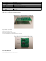
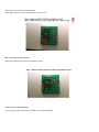
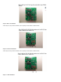
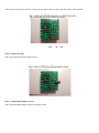
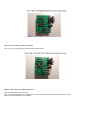
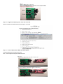
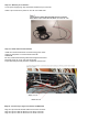
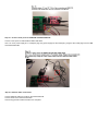
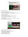
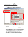
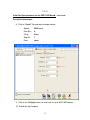
Home Energy Monitor
PART NO.
This project will allow the monitoring of AC voltage and current for an entire home. The data collected is then used in calculating Real
Time KW usage, KHW, RMS AC Voltage and Current, and power factor.
Enter the cost per KW from your electric bill to check if the power company is accurately measuring your POWER USAGE! It's very
interesting to visualize how appliances operate and can detect if one needs to be replaced or not working properly.
This is a great project to learn more about your power usage in the home and what appliances or people in you household that use
the most electricity.
Time Required: 12 hours depending on experience
Experience Level: Intermediate
Required tools and parts:
Can use the custom PCB and only have to solder components to sensor board
or can use a protoboard and wire wrap components.
Also Will Need :
PIC16F88 firmware to operate sensor board.
PC software to interface with sensor board.
Soldering gun: 129040 Solder:94570
screw driver, wire cutters, pliers
If not using custom PCB, Wire Wrap items needed.
Wire Wrap Tool: 2150361 Wire Wrap wire: 22631,22665
18 pin WW socket: 94482 20 pin WW socket: 38632
Protoboard,2-7/16X4: 263207
Bill of Materials:
Qty
Jameco SKU
Component Name
1
2124322
U3:Serial to Ethernet Gateway Module
1
312733
U1:MCU 8-Bit PIC16F88
6
690620
R1-R6:100 ohm Resistor
1
106163
U2:RS-232 interface chip
2
151116
C1-C2:0.1uF Ceramic Disc Capacitor
3
29891
C5-C7:10uF Ceramic Disc Capacitor
2
15405
C3-C4:22pf 50 Volt Ceramic Disc Capacitor
5
691104
R9, R11-R14:10K ohm Resistor
2
691500
R7-R8:470K ohm Resistor
1
691340
R10:100K ohm Resistor
1
2006713
LED3:LED Uni-Color Red 635nm 2-Pin T-1
4
697629
LED2,LED4-LED6:Uni-Color Green
1
325068
X1:20MHz Crystal
1
1940740
PS1/2:5vdc Power Supply
Power supply for HEM PCB and Serial to Ethernet Gateway Module PCB.
1
2
101258
PS3:12VAC power Supply
CT1,CT2: 0- 200 AMP CT
Non-invasive AC current sensor SCT-019 (200A max)
3
2 pin cable/connector for CT/VAC
2-PIN CONNECTOR W/HEADER, .10"
1
101179
PS2: PCB Plug
JACK,DC POWER,MALE,2.1mm,SOLDER EYELET TERMINALS,PC MOUNT
2
690540
1
104978
CONNECTOR DSUB, RIGHT ANGLE, DB-9F
1
697688
LED1:Uni-Color Yellow
1
R15, R16: 47 OHM,1/4 WATT,5%
2.1MM COAX PLUG Y-ADAPTER, FEM - 2 MALE
Only use one 5vdc power supply
1
65585
Socket IC 18 Pin
1
38623
Socket IC 20 Pin
Step 1 - PCB Mounting
Install 4 ea 4-40 x 1" bolts/nuts to support PCB off the table.
Step 2 - U1/U2) chip sockets
Add 2 ea (U1/U2) chip sockets.
Place socket on PCB and solder into place.
Try not to hold soldering iron on board for more than 3 seconds.
Step 3 - (X1) 20MHz crystal
Add 1 ea (X1) 20MHz crystal and solder to board.
Step 4 - (C3,C4) 22pF capacitors
Add 2 ea (C3,C4) 22pF capacitors and solder to board.
Step 5 - (C1, C2) 0.1uF Capacitors
Add 2 ea (C1, C2) 0.1uF capacitors and solder to board.
Step 6 - (LED1-6) LEDS
Add 6 ea (LED1-6) LEDS and solder to board.
(Note: Watch Polarity, + lead is longer than the - lead on LED)
Step 7 - (R1-R6) 100 ohm resistors
Add 6 ea (R1-R6) 100 ohm resistors and solder to board.
Step 8 - (C5-C7) 10uF Capacitors
Add 3 ea (C5-C7) 10uF capacitors and solder to board. (Watch Polarity)
Step 9 - Phase "A" Resistors
Add 2 ea (R11, R12) 10k ohm resistors, and 1 ea (R15) 47 ohm resistor. Solder to board.
Step 10 - Phase "B" Resistors
Add 2 ea (R13, R14) 10k ohm resistors, and 1 ea (R16) 47 ohm resistor. Solder to board.
Step 11 - "VAC" Resistors
Add 2 ea (R7, R8) 470k ohm resistors, 1 ea (R9) 10k ohm resistor and 1 ea (R10) 100k ohm resistor. Solder to board.
Step 12 - (PS2) Power Plug
Add 1 ea (PS2) Power Plug and solder to board.
Step 13 - (RS232-DB9F) DSUB connector
Add 1 ea (RS232-DB9F) DSUB connector and solder to board.
Step 14 - (A, B, VAC) 2 pin cable connectors
Add 3 ea (A, B, VAC) 2 pin cable connectors and solder to board.
Step 15 - Insert chips into sockets* (see note)
Insert 1 ea MAX233 chip into U2 socket.
Insert 1 ea PIC16F88 chip into U1 socket. (*Note: need to program PIC16F88 chip before inserting into socket)
PCB component installation is now complete.
Step 16 - Program PIC16F88 chip then insert into U1 socket.
Need to program PIC16F88 chip before inserting into U1 socket.
Step 17 - Connect HEM PCB and WIZ110SR PCB together
Completed HEM PCB and WIZ110SR PCB.
Now, connect together using the DSUB connectors.
Step 18 - Attach 2 pin connectors
Cut off power supply plug, strip wires back and attach 2 pin connector.
Attach 2 pin connectors to phase "A" and "B" CTs cable ends.
Step 19 - Install Current Transformers
Install the current transformers around incoming power wires.
Label one wire phase "A" and the other Phase "B".
WARNING:
Be Very Careful while working inside the energized load center.
Electrical shock can occur and could be deadly.
Proper electrical personal protective equipment must be worn.
Step 20 - Connect 2 pin signal connectors to HEM PCB
Plug the 2 pin VAC transformer cable into the VAC connector.
Plug the 2 pin CT cable for Phase "A" into the A connector.
Plug the 2 pin CT cable for Phase "B" into the B connector.
Step 21 - Connect +5vdc power to HEM PCB and WIZ110SR PCB.
Connect +5vdc power to HEM PCB and WIZ110SR PCB.
Use 1 ea +5vdc power supply and 1 Y-adapter plug. Plug power supply into the female plug. Plug the other male plugs into the HEM
and WIZ110SR PCBs.
Step 22 - Ethernet Cable Connections
Connect Ethernet cable into socket on the WIZ110SR PCB.
Connect other end to Ethernet hub/switch.
Home Energy Monitor interface install is now complete.
Step 23 - Power Up PCBs
Plug in VAC and +5vdc power supplies into 120VAC outlets.
+5vdc, VAC, A, B, LEDS should be on.
WDT and Data transmit LEDs should be turning on/off every 2 seconds.
If the VAC LED is not on, then check connections. Nothing will operate unless VAC signal is present.
Step 24 - Set-Up WIZ110SR PCB
Run the WIZ110SR configuration software.
Please contact [email protected] in order to download the WIZVSP Installer.
See configuration manual for board set-up details.
**See set-up instructions for WIZ110SR (pages 13 to 15 of these instructions)**
Step 25 - Mount PCBs
Home Energy Monitor PCB and WIZ110SR PCB can be mounted inside bottom of load center
housing. Notice LEDS are "ON" when powered up.
Step 26 - HEM hardware Interface in Load Center
Place both PCBs in bottom of load center housing.
Install CTs around incoming power wires and plug into HEM PCB.
Plug in VAC transformer into HEM PCB.
Plug in +5vdc into HEM and WIZ110SR PCBs.
Plug Ethernet cable into the WIZ110SR PCB.
Plug in the VAC transformer into AC outlet.
Plug in the +5vdc Power Supply into AC outlet.
Step 27 - Install the HEM software
Install the HEM software on a PC.
See User Manual for install and operating details.
7-2-13
Initial Set-Up Instructions for the WIZ110SR Board.
1. Connect WIZ110SR board to the Ethernet hub that is also connected to
your computer. Use a LAN cable (RJ45 CAT-5 Ethernet cable)
2. Connect the 5vdc power supply to the board.
Run the “Configuration Tool” Software:
Launch WIZ1x0SR_105SR_CFG_V3_0_2.exe
This window will appear:
1
1. Search for the WIZ110SR board. Click on the “Search” button.
1
7-2-13
Initial Set-Up Instructions for the WIZ110SR Board.
2. After the search is complete:
A. The MAC address of the board will be listed in the board list to the left.
B. The fields to the right will now contain network information.
2A
6
3
2B
4
5
3. To get an Local IP address assigned automatically, click on the “DHCP”
option button.
4. Click on the “Setting” button, to send new set-up to WIZ110SR board.
5. Click on the “Search” button, to retrieve the new board set-up parameters.
6. To make sure that the Local IP address does not change, click on the
“Static” option button and then repeat steps 4 and 5 above.
7. Enter IP address in the HEM software program under Set-Up tab.
2
7-2-13
Initial Set-Up Instructions for the WIZ110SR Board. (continued)
Set-Up Serial Interface:
8. Click on “Serial” Tab and make changes below:
Speed:
9600 baud
Data Bits:
8
Parity:
Even
Stop Bit:
1
Flow:
none
8
9
9. Click on the “Setting” button, to send new set-up to WIZ110SR board.
10. Board Set-Up Complete.
3