1
2001
Air-Conditioners For Building Application
TECHNICAL & SERVICE MANUAL
Series PEFY Ceiling Concealed
<Indoor unit>
Models
PEFY-P20VML-A
PEFY-P25VML-A
PEFY-P32VML-A
CONTENTS
SAFETY PRECAUTIONS ·························1
1. FEATURES ···········································3
2. PART NAMES AND FUNCTIONS ········4
3. SPECIFICATION ···································6
4. OUTLINES AND DIMENSIONS············8
5. WIRING DIAGRAM·······························9
6. REFRIGERANT SYSTEM DIAGRAM····10
7. TROUBLE SHOOTING·······················11
8. DISASSEMBLY PROCEDURE···········14
INDOOR UNIT
SAFETY PRECAUTIONS
1.
Before installation and electric work
s Before installing the unit, make sure you read all the
“Safety precautions”.
s The “Safety precautions” provide very important
points regarding safety. Make sure you follow them.
•
•
•
s This equipment may cause the adverse effect on the
same supply system.
s Please report to or take consent by the supply authority before connection to the system.
•
•
Symbols used in the text
Warning:
Describes precautions that should be observed to prevent danger
of injury or death to the user.
•
Caution:
Describes precautions that should be observed to prevent damage
to the unit.
•
Symbols used in the illustrations
: Indicates an action that must be avoided.
: Indicates that important instructions must be followed.
•
: Indicates a part which must be grounded.
: Indicates that caution should be taken with rotating parts. (This
symbol is displayed on the main unit label.) <Color: Yellow>
: Beware of electric shock (This symbol is displayed on the main
unit label.) <Color: Yellow>
•
Warning:
Carefully read the labels affixed to the main unit.
•
Warning:
•
•
•
•
•
1
Ask the dealer or an authorized technician to install the air conditioner.
- Improper installation by the user may result in water leakage, electric shock, or fire.
Install the air unit at a place that can withstand its weight.
- Inadequate strength may cause the unit to fall down, resulting in
injuries.
Use the specified cables for wiring. Make the connections securely so that the outside force of the cable is not applied to the
terminals.
- Inadequate connection and fastening may generate heat and cause
a fire.
Prepare for typhoons and other strong winds and earthquakes
and install the unit at the specified place.
- Improper installation may cause the unit to topple and result in
injury.
Always use an air cleaner, humidifier, electric heater, and other
accessories specified by Mitsubishi Electric.
- Ask an authorized technician to install the accessories. Improper
installation by the user may result in water leakage, electric shock,
or fire.
•
Never repair the unit. If the air conditioner must be repaired,
consult the dealer.
- If the unit is repaired improperly, water leakage, electric shock, or
fire may result.
Do not touch the heat exchanger fins.
- Improper handling may result in injury.
If refrigerant gas leaks during installation work, ventilate the
room.
- If the refrigerant gas comes into contact with a flame, poisonous
gases will be released.
Install the air conditioner according to this Installation Manual.
- If the unit is installed improperly, water leakage, electric shock, or
fire may result.
Have all electric work done by a licensed electrician according
to “Electric Facility Engineering Standard” and “Interior Wire
Regulations”and the instructions given in this manual and always use a special circuit.
- If the power source capacity is inadequate or electric work is performed improperly, electric shock and fire may result.
Securely install the cover of control box and the panel.
- If the cover and panel are not installed properly,dust or water may
enter the outdoor unit and fire or electric shock may result.
When installing and moving the air conditioner to another site,
do not charge the it with a refrigerant different from the refrigerant (R22) specified on the unit.
- If a different refrigerant or air is mixed with the original refrigerant,
the refrigerant cycle may malfunction and the unit may be damaged.
If the air conditioner is installed in a small room, measures
must be taken to prevent the refrigerant concentration from
exceeding the safety limit even if the refrigerant should leak.
- Consult the dealer regarding the appropriate measures to prevent the safety limit from being exceeded. Should the refrigerant
leak and cause the safety limit to be exceeded, hazards due to
lack of oxygen in the room could result.
When moving and reinstalling the air conditioner, consult the
dealer or an authorized technician.
- If the air conditioner is installed improperly, water leakage, electric shock, or fire may result.
After completing installation work, make sure that refrigerant
gas is not leaking.
- If the refrigerant gas leaks and is exposed to a fan heater, stove,
oven, or other heat source, it may generate noxious gases.
Do not reconstruct or change the settings of the protection
devices.
- If the pressure switch, thermal switch, or other protection device
is shorted and operated forcibly, or parts other than those specified
by Mitsubishi Electric are used, fire or explosion may result.
2.
Precautions for devices that use
R407C refrigerant
Caution:
•
•
•
•
•
•
•
•
•
•
Do not use the existing refrigerant piping.
- The old refrigerant and refrigerator oil in the existing piping contains a large amount of chlorine which may cause the refrigerator
oil of the new unit to deteriorate.
Use refrigerant piping made of C1220 (CU-DHP) phosphorus
deoxidized copper as specified in the *JIS H3300 “Copper and
copper alloy seamless pipes and tubes”. In addition, be sure
that the inner and outer surfaces of the pipes are clean and
free of hazardous sulphur, oxides, dust/dirt, shaving particles,
oils, moisture, or any other contaminant.
- Contaminants on the inside of the refrigerant piping may cause
the refrigerant residual oil to deteriorate.
*JIS: Japanese Industrial Standard
Store the piping to be used during installation indoors and keep
both ends of the piping sealed until just before brazing. (Store
elbows and other joints in a plastic bag.)
- If dust, dirt, or water enters the refrigerant cycle, deterioration of
the oil and compressor trouble may result.
Use ester oil, ether oil or alkylbenzene (small amount) as the
refrigerator oil to coat flares and flange connections.
- The refrigerator oil will degrade if it is mixed with a large amount of
mineral oil.
Use liquid refrigerant to fill the system.
- If gas refrigerant is used to seal the system, the composition of
the refrigerant in the cylinder will change and performance may
drop.
Do not use a refrigerant other than R407C.
- If another refrigerant (R22, etc.) is used, the chlorine in the refrigerant may cause the refrigerator oil to deteriorate.
Use a vacuum pump with a reverse flow check valve..
- The vacuum pump oil may flow back into the refrigerant cycle and
cause the refrigerator oil to deteriorate.
Do not use the following tools that are used with conventional
refrigerants.
(Gauge manifold, charge hose, gas leak detector, reverse flow
check valve, refrigerant charge base, vacuum gauge, refrigerant recovery equipment)
- If the conventional refrigerant and refrigerator oil are mixed in the
R407C, the refrigerant may deteriorated.
- If water is mixed in the R407C, the refrigerator oil may deteriorate.
- Since R407C does not contain any chlorine, gas leak detectors
for conventional refrigerants will not react to it.
Do not use a charging cylinder.
- Using a charging cylinder may cause the refrigerant to deteriorate.
Be especially careful when managing the tools.
- If dust, dirt, or water gets in the refrigerant cycle, the refrigerant
may deteriorate.
2
1
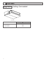
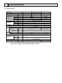
FEATURES
Series PEFY Ceiling Concealed
Indoor unit
Models
3
Cooling capacity/Heating capacity
kW
PEFY-P20VML-A
2.2/2.5
PEFY-P25VML-A
2.8/3.2
PEFY-P32VML-A
3.6/4.0
2
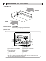
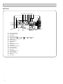
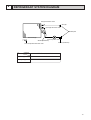
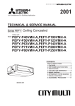
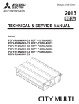
PART NAMES AND FUNCTIONS
● Indoor (Main) Unit
Air outlet
Air inlet
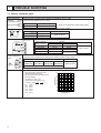
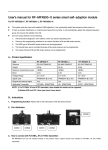
● Remote controller
[PAR-20MAA]
●Once the controls are set, the same operation mode can
be repeated by simply pressing the ON/OFF button.
● Operation buttons
CENTRALLY CONTROLLED
ON
1Hr.
OFF
˚C
CLOCK
CHECK
˚C
STAND BY
DEFROST
1
ERROR CODE
TEMP.
NOT AVAILABLE
FILTER
CHECK MODE
TEST RUN
FUNCTION
ON/OFF
B
2
FILTER
3
CHECK TEST
PAR-20MAA
A
0
TIMER SET
C
4 5 6 87 9
[Room temperature adjustment] Button
[Timer/continuous] Button
[Selecting operation] Button
[Time selection] Button
[Time-setting] Button
5 [Louver] Button
6 [Fan speed adjustment] Button
1
2
3
4
7
8
9
0
A
B
C
[Up/down airflow direction] Button
[Ventilation] Button
[Checking/built-in] Button
[Test run] Button
[Filter] Button
[ON/OFF] Button
Position of built-in room temperature
•Never expose the remote controller to direct sunlight. Doing so can result in the erroneous measurement of room temperature.
•Never place any obstacle around the lower right-hand section of the remote controller. Doing so can
result in the erroneous measurement of room temperature.
4
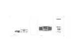
● Display
DC B
A UT Q S
CENTRALLY CONTROLLED
ON
E
F
1Hr.
OFF
˚C
CLOCK
CHECK
ERROR CODE
NOT AVAILABLE
TEMP.
G
(A)
(B)
(C)
(D)
(E)
(F)
(G)
(H)
(I)
(J)
(K)
(L)
(M)
(N)
(O)
(P)
(Q)
(R)
(S)
(T)
(U)
5
FILTER
CHECK MODE
TEST RUN
FUNCTION
˚C
STAND BY
DEFROST
ON/OFF
H
Current time/Timer
Centralized control
Timer ON
Abnormality occurs
Operation mode: COOL, DRY,
Preparing for Heating mode
Defrost mode
Set temperature
Power ON
Louver
Not available function
Ventilation
Function setting mode
Test run mode
Error check mode
Filter sign
Set effective for 1 hr.
Sensor position
Room temperature
Airflow
Fan speed
I KL J
AUTO,
FAN,
HEAT
R
P
O
N
M
3
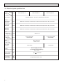
SPECIFICATION
3-1. Specification
PEFY-P20VML-A
Power source
Cooling capacity ❇ 1
Heating capacity ❇ 1
Cooling
Power consumption
(50/60Hz)
Heating
Cooling
Current
Heating
External finish
Height
Dimension
Width
Depth
Net weight
Heat exchanger
Type
Airflow rate
Fan (Lo-Mid-Hi)
External static
pressure
Type
Motor
Output
Air filter
Gas
Refrigerant
pipe dimension
(Brazing)
Liquid
(Brazing)
Drain pipe dimension
Noise level (Lo-Mid-Hi)
kW
kW
kW
kW
A
A
mm
mm
mm
kg
m3/min
PEFY-P25VML-A
PEFY-P32VML-A
~220-240V 50Hz / 60Hz
2.2
2.8
3.6
2.5
3.2
4.0
0.05/0.06
0.07/0.09
0.05/0.06
0.07/0.09
0.24/0.28
0.32/0.42
0.24/0.28
0.32/0.42
Galvanized steel plate
225
720
550
18
Cross fin (Aluminum plate fin and copper tube)
Sirocco fan✕ 1
5.4-6.5-7.9
6.0-7.5-9.5
Pa
5
kW
Single phase induction motor
0.023
PP Honeycomb fabric (washable)
mm
ø 12.7
mm
ø 6.35
dB(A)
R1 (External thread)
29-33-36
0.032
30-35-40
Note: ❇ 1 Cooling/Heating capacity indicates the maximum value at operation under the following condition.
Cooling : Indoor 27˚CDB/19˚CWB,Outdoor 35˚CDB (WR2: water 30˚C)
Heating : Indoor 20˚CDB,Outdoor 7˚CDB/6˚CWB (WR2: water 20˚C)
6
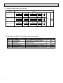
3-2. Electrical parts specifications
Model
Parts
name
Symbol
PEFY-P25VML-A
PEFY-P20VML-A
PEFY-P40VML-A
Tranrsformer
T
(Primary) 50/60Hz 220-240V (Secondry) (23.5V 0.9A)
Room
temperature
thermistor
TH21
Resistance 0˚C/15kW,10˚C/9.6kW,20˚C/6.3kW,25˚C/5.4kW,30˚C/4.3kW,40˚C/3.0kW
Liquid pipe
thermistor
TH22
Resistance 0˚C/15kW,10˚C/9.6kW,20˚C/6.3kW,25˚C/5.4kW,30˚C/4.3kW,40˚C/3.0kW
Gas pipe
thermistor
TH23
Resistance 0˚C/15kW,10˚C/9.6kW,20˚C/6.3kW,25˚C/5.4kW,30˚C/4.3kW,40˚C/3.0kW
Fuse
FUSE
(Indoor controller board)
Fan motor
(with InnerMF1,2
thermostat)
250V 6.3A
4-pole Output 23W
CRC4417AB
Innerthermostat
(Fan motor)
Fan motor
capacitor
OFF 135˚C±5˚C
ON 95˚C±15˚C
C1
Linear
expansion valve LEV
Power supply
terminal bed
TB2
Transmission
terminal bed
TB5
TB15
7
4-pole Output 32W
CRC4418AB
1.5µF✕440V
2.0µF✕440V
DC12V Stepping motor drive
port dimension ø3.2(0~2000pulse)
EDM-402MD
(L,N,
) 330V 30A
(1,2),(M1,M2,S) 300V 10A
Air filter
23
1)
3
Bottom plate
2
510
550 (
459(Lifting bolt pitch)
Control box
Terminal bed
(Transmission)
Terminal bed
(Power source)
Lifting bolt
Air inlet
80
113
148
1
55
15
30
15
Air outlet
12-ø3
14
2X3-ø3
582
42.5
301
5
Access door
450
Ceiling surface
25
300
50
150
450
500
50
Reguired space for service and maintenance
150
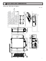
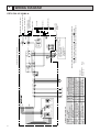
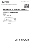
Detailed chart around the air intake duct frange (
(Duct and frange should be supplied in the field)
301
Make the access door at the appointed position properly for service maintenance.
204.5
65.5
5
3)
Note1.Use M10 screw for the lifting bolt (field supply).
2.Keep the service space for the maintenance from
the bottom when the heat exchanger is cleaned.
3.The direction of air intake can be changed from the
bottom to the rear by attaching the bottom plate
to the air intake side.
4.Drain Pan is changeable from right and left.
5.The dimension is changed, in case the optional
long-life filter is attached.
Rear Air-Intake spec. : Depth is increased by 30mm ( 1)
Bottom Air-Intake spec. : Height is increased by 30mm ( 2)
Refrigerant piping brazing connection
(gas ø12.7 copper tube) :LP ··················· 1
Refrigerant piping brazing connection
(liquid ø6.35 copper tube) :HP ··············· 2
Drain piping connection R1 (External thread) ········ 3
12
189
9
664(Lifting bolt pitch)
610
80
50
16
14
127
13.5
50
50
50X11= 550
2)
225 (
3)
More than 20mm
710
The part air intake duct is attached. (
(When the air intake duct is used)
More than 20mm
720
4
OUTLINES AND DIMENSIONS
Indoor Unit PEFY-P20· 25· 32VML-A
Unit : mm
8
9
SYMBOL
MF
C
I.B
A.B
TB2
TB5
TB15
F1
T
LEV
S.B
X04~X06
9 0 1
2
3
6 5 4
TH22
21
TH23
21
21
LEV
654321
CN60
3
CNT
1 31
T
CN3T
F1
AC250V
6.3A F
13
31
13 57
9 8 54 3 1
C
986
98
(Blue)
31
4 31
TB15(TRANSMISSION TERMINAL BED)
2
TO MA REMOTE CONTROLLER
1
PE
3
TB2
TO DUCT
L
N
PE
POWER SUPPLY
~ 220,230,240V
50,60Hz
BREAKER(16A)
FUSE(16A)
PULL BOX
TO NEXT INDOOR UNIT
TB5(TRANSMISSION TERMINAL BED)
S(SHIELD)
M2
TO OUTDOOR UNIT
M1
BC CONTROLLER
REMOTE CONTROLLER
S.B
CN1 1
2
1
3
1
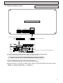
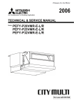
The motor connector is connected
with 230V,240V power at factory shipment.
If 220 power is used,
insert the attachment.
Color/Power source
White/230V,240V
Blue/220V
MF
DSA1
ZNR1
CN2M
*insert
X04
FAN3
X06 X05
(White) 9 8 6 5 4 3 1
*A
CND CNP
ZNR
X01
CN3A
I.B
NAME
Thermistor (inlet temp.detection)
Thermistor (piping temp.detection/liquid)
Thermistor (piping temp.detection/gas)
NOTE;1.The wirings to TB2,TB5 shown in dotted line are field work.
Switch (1st digit address set)
2.Mark
indicates terminal bed, connector, board
Switch (2nd digit address set)
insertion connector or fastening connector of control board.
Switch (connection No.set)
Switch(for mode selection)
Switch(for capacity code)
*A Capacitor
Switch(for mode selection)
MODELS 20/25
1.5mF
Switch(for model selection)
Switch(for voltage selection)
MODEL 32
2.0mF
TH21
SYMBOL
TH21
TH22
TH23
SW11(A.B)
SW12(A.B)
SW14(A.B)
SW1(A.B)
SW2(I.B)
SW3(I.B)
SW4(I.B)
SW5(A.B)
SW11
(1st digit)
8
7
NAME
Fan motor
*A Capacitor (for MF)
Indoor controller board
Address board
Power source terminal bed
Transmission terminal bed
Transmission terminal bed
Fuse AC250V 6.3A F
Transformer
Electronic linear expan. valve
Surge absorber board
Aux.relay
SYMBOL EXPLANATION
12 3 4 5 6
A.B
CN82
CN62
8
SW1
SW5
7
6
0
1
F
9 0 1
E 2
5
D
3
2
8
C
4
4
3
7
BA
5
3
6 5 4
9876
2
SW14
SW12
1
(Connection No.) (2nd digit)
21
1
SW4 SW3 SW2
2
3 CN42
4
1
2
3
4
5 CN81
6
7
8
CN20 CN21 CN29 CN31
INSIDE SECTION OF CONTROL BOX
5
WIRING DIAGRAM
PEFY-P20· 25· 32VML-A
6
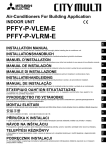
REFRIGERANT SYSTEM DIAGRAM
Gas pipe thermistor TH23
Gas pipe
Liquid pipe thermistor TH22
Brazed joints
Heat exchanger
Linear expansion valve
Strainer (#100mesh)
Room temperature thermistor TH21
Capacity
Item
Strainer (#100mesh)
PEFY-P20,25,32VML-A
Gas pipe
ø12.7<1/2>
Liquid pipe
ø6.35<1/4>
10
7
TROUBLE SHOOTING
7-1. How to check the parts
Parts name
Check points
Room temperature
thermistor
(TH21)
Liquid pipe thermistor
(TH22)
Gas pipe thermistor
(TH23)
Disconnect the connector, then measure the resistance using a tester.
(Sorrounding temperature 10¡C~30¡C)
Trans
Disconnect the connector and measure the resistance using a tester.
Abnormal
Open or short
CNT
3T
CN3T
3
Normal
4.3kW~9.6kW
1
Normal
App.15W
App.4W
CNT(1)-(3)
CN3T(1)-(3)
Fan motor PEFY-P20· 25· 32
Relay connector
Protector
Gray
Blue
Brown
Black
Orange
Red
White
Linear expansion
CN60
valve
White
Yellow
Orange
LEV
Blue
Red
Brown
1
2
3
4
5
6
1
3
4
5
6
8
(Refer to the thermistor characteristic graph)
Abnormal
Open or short
Measure the resistance between the terminals using a tester.
Motor terminal
or
Relay connector
Gray-Orange
Gray-Black
Gray-Brown
Gray-Blue
Normal
P20· 25
281.4W
307.9W
347.0W
420.4W
P32
233.6W
254.8W
325.0W
399.3W
9
Disconnect the connector then measure the resistance valve using a tester.
Normal
Abnormal
(1)-(5)
(2)-(6)
(3)-(5)
(4)-(6)
White-Red Yellow-Brown Orange-Red Blue-Brown
Open or short
150W ±10%
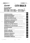
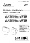
<Thermistor characteristic graph>
Thermistor R0=15kW ± 3%
Fixed number of B=3480kW ± 2%
1
Rt=15exp { 3480( 273+t
0˚C
10˚C
20˚C
25˚C
30˚C
40˚C
11
15kW
9.6kW
6.3kW
5.2kW
4.3kW
3.0kW
1
)}
273
50
40
Resistance (kW)
Room temperature thermistor(TH21)
Liquid pipe thermistor(TH22)
Gas pipe temperature thermistor(TH23)
Drain sensor(DS)
30
20
10
0
-20 -10 0 10 20 30 40 50
Temperature (˚C)
(at 20˚C)
Abnormal
Open or short
7-2. Setting of address switch
Make sure that power source is turning off.
Indoor unit control board
SW2
SW 3
SW4
< At delivery (All models)> SW 1
1 2 3 4 5 6 7 8 9 10
240V 220V
2
1
SWA
SWC
8
10
1
JP1
FP-AD-S 3
< At delivery (All models)>
1 2 34
SW1
ON
W254613G03
SW 4
ON
OFF
0
CN82
SW12
SW11
0
0
1
6
CN62 1
JP2
JP3
JP4
ON
OFF
Refer to the next page for SW2,SW3 setting.
SW5
SW14
MADE IN JAPAN
1)In case using network remote controller, address is set by rotary switches.(SW11,SW12)
* It is not necessary setting address in case of using unit remote controller.
Indoor unit do not run without address setting in field.
2) Indoor unit address setting rule is different by each field work.
Refer to install manual of outdoor unit , operate the address setting.
3)Setting the address is combination of SW11(1st digit address setting) and SW12(2nd digit address setting).
Address " 3 " setting is composed SW11 " 3 " and SW12 " 0 " .
Address " 25 " setting is composed SW11 " 5 " and SW12 " 2 " .
12
7-3. Setting of Dip-switch (at delivery)
Models
Dip-SW
SW1
PEFY-P20VML
ON
OFF
1 2 3 4 5 6 7 8 910
ON
OFF
123456
SW1
PEFY-P25VML
ON
OFF
1 2 3 4 5 6 7 8 910
123456
ON
OFF
1 2 3 4 5 6 7 8 910
1 2 3 4 5 6 7 8 910
123456
S W5
220V
240V
ON
OFF
S W5
220V
240V
S W4
ON
OFF
1 2 34
S W3
ON
OFF
ON
OFF
1 2 34
S W3
ON
OFF
SW2
ON
OFF
S W4
ON
OFF
1 2 3 4 5 6 7 8 910
SW2
ON
OFF
SW1
PEFY-P32VML
S W3
SW2
ON
OFF
ON
OFF
1 2 3 4 5 6 7 8 910
SWC
(Standard)
S W4
1 2 34
SWA
1
ON
OFF
S W5
220V
240V
7-4. Function the LED of the indoor unit service board
LED
LED1
LED2
LED3
LED4
LED5
13
NAME
UR Transmission
LED function in normal
Transmission of unit remote controller
7-4. Function the LED
of the indoor
unit ofservice
board
UR Transmission
Transmission
and reseption
unit
and reseption
Main power source
5V power source
Transmission power source
remote controller
Power source supply (indoor unit 200V)
5V power source supply
Reception M-NET transmission power source
Blink
Blink
Light up
Light up
Light up
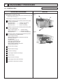
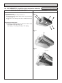
8
DISASSEMBLY PROCEDURE
Be careful on removing heavy parts.
8-1. CONTROL BOX
OPERATING PROCEDURE
1.Removing the control box cover
(1) Remove the fixing screws (two) of the control box (A), and
remove the cover. (Fig. 1)
PHOTOS
fig.1
(A)
*At this stage, the following servicing is possible.
1 Operation and check of the switches (listed below) which
are on the control board.
• Dip switch SW2 • • • • • Capacity code setting
• Dip switch SW3 • • • • • Function change
• Dip switch SW4 • • • • • Model code setting
2 Operation and check of the switches (listed below) which
are on the adress board.
• Rotary switches SW11, 12 • • Address setting
• Rotary switch SW14 • • • • Branch port setting
• Dip switch SW1 • • • • • • • •Function change (main)
fig.2
3 Connection check of the lead wires (listed below) which
are connected to the controller board.
• Power supply lead wire.
• Network remote contoller transmission lead wire.
• Fan motor lead wire.
• LEV lead wire
• Intake air sensor lead wire
• Liquid piping sensor lead wire
• Gas piping sensor lead wire
• Power supply transformer lead wire
• Address board lead wire
4 Control board exchange
5 Address board exchange
6 Condenser exchange
7 Power supply transformer exchange
8 Arrest exchange
9 Intake air sensor exchange
10 Power supply terminal bed exchange
11 Transmission terminal bed exchange
14
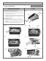
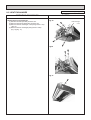
Be careful on removing heavy parts.
8-2. FAN and FAN MOTOR
OPERATING PROCEDURE
1.Removing the fan casing and sirocco fan.
(1) Remove the bottom plate 1. (fixing screws : six) (Fig. 3)
PHOTOS
fig.3
(2) Remove the fixing screws (three) of the fan casing, and turn
it in direction of arrow. (Fig. 4)
Bottom plate1
(3) Remove the fixing screws (two) of the fan casing, and loosen
the set screw of the sirocco fan, and remove the fan casing
and sirocco fan. (Fig. 5)
2.Removing the fan motor.
(1) Remove the control box. (fixing screws : three) (Fig. 7)
(2) Move the control box to place that is not block operation.
(Fig. 8)
(3) Remove the fan motor cable connector in the control box,
and remove the screws of the motor support. (Fig. 9)
fig.5
fig.4
Fan casing
Set screw
fig.6
fig.8
15
fig.7
fig.9
Fan motor
cable connec
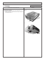
Be careful on removing heavy parts.
8-3. DRAINPAN
OPERATING PROCEDURE
1.Removing the drainpan.
(1) Remove the fixing screw (one) of the drainpan.(Fig. 10).
(2) Slide the drainpan in the order of arrow ①,➁,③, and remove
the drainpan. (Fig. 11)
PHOTOS
fig.10
fig.11
1
2
3
16
8-4. LEV,THERMISTOR (Liquid/Gas piping temperature detection)
OPERATING PROCEDURE
1.Removing the LEV.
(1) Remove the drainpan with procedure 8-3.
(2) Remove the bottom plate 2 (fixing screws : six), and remove
the plate.(Fig. 12)
(3) Remove the LEV driving motor with a double spanner.(Fig.
13)
Be careful on removing heavy parts.
PHOTOS
fig.12
2.Removing the thermistors.
(1) Remove the thermistors from the thermistor holders which
are installed on the piping.(Fig. 14)
(liquid piping : fine piping , gas piping : thick piping)
fig.13
LEV
fig.14
Thermistor
17
Be careful on removing heavy parts.
8-5. HEAT EXCHANGER
OPERATING PROCEDURE
1.Removing the heat exchanger.
(1) Remove the drainpan with procedure 8-3.
(2) Remove the bottom plate2 with procedure 8-4.
(3) Remove the heat exchanger cover.(fixing screws : four)
(Fig. 15)
(4) Remove the heat exchanger.(fixing screws : three)
(Fig. 16),(Fig. 17)
PHOTOS
fig.15
Heat exchanger
cover
fig16
fig.17
18
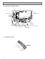
8-6. CONTROL BOX INSIDE LAYOUT
CNP
CND
X06 X05
CN82
SW14 SW12 SW1
Indoor unit
contoller board
X04
SW1
SWA SWC SW5
Address board
CNT
FAN3
CN62
L
N
1
2
Condenser
(for motor)
Transmission terminal bed
Trans
DSA board
Power sourse
terminal bed
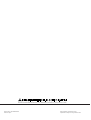
8-7. SENSOR POSITION
Gas sensor
Liquid sensor
19
HEAD OFFICE: MITSUBISHI DENKI BLDG., 2-2-3, MARUNOUCHI, CHIYODA-KU, TOKYO 100-8310, JAPAN
Issued in May. 2001 MEE01K050
Printed in Japan
New publication, effective May. 2001
Specifications subject to change without notice