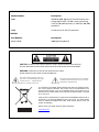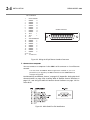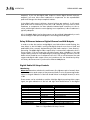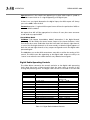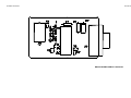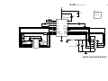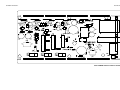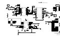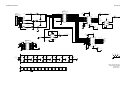
1
Operating Manual OPTIMOD-AM 9400 Digital Audio Processor Version 1.2 Software IMPORTANT NOTE: Refer to the unit’s rear panel for your Model Number. Model Number: Description: 9400 OPTIMOD 9400, Digital I/O, Five-band stereo processing, digital radio / HD AM / netcast processing, 115V (for 90-130V operation) or 230V (for 200-250V operation) 9400J As above, but for 90-117V operation. MANUAL: Part Number: Description: 96129.120.03 9400 Operating Manual CAUTION: TO REDUCE THE RISK OF ELECTRICAL SHOCK, DO NOT REMOVE COVER (OR BACK). NO USER SERVICEABLE PARTS INSIDE. REFER SERVICING TO QUALIFIED SERVICE PERSONNEL. WARNING: TO REDUCE THE RISK OF FIRE OR ELECTRICAL SHOCK, DO NOT EXPOSE THIS APPLIANCE TO RAIN OR MOISTURE. This symbol, wherever it appears, alerts you to the presence of uninsulated dangerous voltage inside the enclosure voltage that may be sufficient to constitute a risk of shock. This symbol, wherever it appears, alerts you to important operating and maintenance instructions in the accompanying literature. Read the manual. In accordance to the WEEE (waste electrical and electronic equipment) directive of the European Parliament, this product must not be discarded into the municipal waste stream in any of the Member States. This product may be sent back to your Orban dealer at end of life where it will be reused or recycled at no cost to you. If this product is discarded into an approved municipal WEEE collection site or turned over to an approved WEEE recycler at end of life, your Orban dealer must be notified and supplied with model, serial number and the name and location of site/facility. Please contact your Orban dealer for further assistance. www.orban.com IMPORTANT SAFETY INSTRUCTIONS All the safety and operating instructions should be read before the appliance is operated. Retain Instructions: The safety and operation instructions should be retained for future reference. Heed Warnings: All warnings on the appliance and in the operating instructions should be adhered to. Follow Instructions: All operation and user instructions should be followed. Water and Moisture: The appliance should not be used near water (e.g., near a bathtub, washbowl, kitchen sink, laundry tub, in a wet basement, or near a swimming pool, etc.). Ventilation: The appliance should be situated so that its location or position does not interfere with its proper ventilation. For example, the appliance should not be situated on a bed, sofa, rug, or similar surface that may block the ventilation openings; or, placed in a built-in installation, such as a bookcase or cabinet that may impede the flow of air through the ventilation openings. Heat: The appliance should be situated away from heat sources such as radiators, heat registers, stoves, or other appliances (including amplifiers) that produce heat. Power Sources: The appliance should be connected to a power supply only of the type described in the operating instructions or as marked on the appliance. Grounding or Polarization: Precautions should be taken so that the grounding or polarization means of an appliance is not defeated. Power-Cord Protection: Power-supply cords should be routed so that they are not likely to be walked on or pinched by items placed upon or against them, paying particular attention to cords at plugs, convenience receptacles, and the point where they exit from the appliance. Cleaning: The appliance should be cleaned only as recommended by the manufacturer. Non-Use Periods: The power cord of the appliance should be unplugged from the outlet when left unused for a long period of time. Object and Liquid Entry: Care should be taken so that objects do not fall and liquids are not spilled into the enclosure through openings. Damage Requiring Service: The appliance should be serviced by qualified service personnel when: The power supply cord or the plug has been damaged; or Objects have fallen, or liquid has been spilled into the appliance; or The appliance has been exposed to rain; or The appliance does not appear to operate normally or exhibits a marked change in performance; or The appliance has been dropped, or the enclosure damaged. Servicing: The user should not attempt to service the appliance beyond that described in the operating instructions. All other servicing should be referred to qualified service personnel. The Appliance should be used only with a cart or stand that is recommended by the manufacturer. Safety Instructions (European) Notice For U.K. Customers If Your Unit Is Equipped With A Power Cord. WARNING: THIS APPLIANCE MUST BE EARTHED. The cores in the mains lead are coloured in accordance with the following code: GREEN and YELLOW - Earth BLUE - Neutral BROWN - Live As colours of the cores in the mains lead of this appliance may not correspond with the coloured markings identifying the terminals in your plug, proceed as follows: The core which is coloured green and yellow must be connected to the terminal in the plug marked with the letter E, or with the earth symbol, or coloured green, or green and yellow. The core which is coloured blue must be connected to the terminal marked N or coloured black. The core which is coloured brown must be connected to the terminal marked L or coloured red. The power cord is terminated in a CEE7 / 7 plug (Continental Europe). The green / yellow wire is connected directly to the unit's chassis. If you need to change the plug and if you are qualified to do so, refer to the table below. WARNING: If the ground is defeated, certain fault conditions in the unit or in the system to which it is connected can result in full line voltage between chassis and earth ground. Severe injury or death can then result if the chassis and earth ground are touched simultaneously. Conductor L LIVE WIRE COLOR Normal Alt BROWN BLACK N NEUTRAL BLUE WHITE E EARTH GND GREEN-YELLOW GREEN AC Power Cord Color Coding Safety Instructions (German) Gerät nur an der am Leistungsschild vermerkten Spannung und Stromart betreiben. Sicherungen nur durch solche, gleicher Stromstärke und gleichen AbschalAMerhaltens ersetzen. Sicherungen nie überbrücken. Jedwede Beschädigung des Netzkabels vermeiden. Netzkabel nicht knicken oder quetschen. Beim Abziehen des Netzkabels den Stecker und nicht das Kabel enfassen. Beschädigte Netzkabel sofort auswechseln. Gerät und Netzkabel keinen übertriebenen mechanischen Beaspruchungen aussetzen. Um Berührung gefährlicher elektrischer Spannungen zu vermeiden, darf das Gerät nicht geöffnet werden. Im Fall von Betriebsstörungen darf das Gerät nur Von befugten Servicestellen instandgesetzt werden. Im Gerät befinden sich keine, durch den Benutzer reparierbare Teile. Zur Vermeidung von elektrischen Schlägen und Feuer ist das Gerät vor Nässe zu schützen. Eindringen von Feuchtigkeit und Flüssigkeiten in das Gerät vermeiden. Bei Betriebsstörungen bzw. nach Eindringen von Flüssigkeiten oder anderen Gegenständen, das Gerät sofort vom Netz trennen und eine qualifizierte Servicestelle kontaktieren. Safety Instructions (French) On s'assurera toujours que la tension et la nature du courant utilisé correspondent bien à ceux indiqués sur la plaque de l'appareil. N'utiliser que des fusibles de même intensité et du même principe de mise hors circuit que les fusibles d'origine. Ne jamais shunter les fusibles. Eviter tout ce qui risque d'endommager le câble seceur. On ne devra ni le plier, ni l'aplatir. Lorsqu'on débranche l'appareil, tirer la fiche et non le câble. Si un câble est endommagé, le remplacer immédiatement. Ne jamais exposer l'appareil ou le câble ä une contrainte mécanique excessive. Pour éviter tout contact averc une tension électrique dangereuse, on n'oouvrira jamais l'appareil. En cas de dysfonctionnement, l'appareil ne peut être réparé que dans un atelier autorisé. Aucun élément de cet appareil ne peut être réparé par l'utilisateur. Pour éviter les risques de décharge électrique et d'incendie, protéger l'appareil de l'humidité. Eviter toute pénétration d'humidité ou fr liquide dans l'appareil. En cas de dysfonctionnement ou si un liquide ou tout autre objet a pénétré dans l'appareil couper aussitôt l'appareil de son alimentation et s'adresser à un point de service aprésvente autorisé. Safety Instructions (Spanish) Hacer funcionar el aparato sólo con la tensión y clase de corriente señaladas en la placa indicadora de características. Reemplazar los fusibles sólo por otros de la misma intensidad de corriente y sistema de desconexión. No poner nunca los fusibles en puente. Proteger el cable de alimentación contra toda clase de daños. No doblar o apretar el cable. Al desenchufar, asir el enchufe y no el cable. Sustituir inmediatamente cables dañados. No someter el aparato y el cable de alimentación a esfuerzo mecánico excesivo. Para evitar el contacto con tensiones eléctricas peligrosas, el aparato no debe abrirse. En caso de producirse fallos de funcionamiento, debe ser reparado sólo por talleres de servicio autorizados. En el aparato no se encuentra ninguna pieza que pudiera ser reparada por el usuario. Para evitar descargas eléctricas e incendios, el aparato debe protegerse contra la humedad, impidiendo que penetren ésta o líquidos en el mismo. En caso de producirse fallas de funcionamiento como consecuencia de la penetración de líquidos u otros objetos en el aparato, hay que desconectarlo inmediatamente de la red y ponerse en contacto con un taller de servicio autorizado. Safety Instructions (Italian) Far funzionare l'apparecchio solo con la tensione e il tipo di corrente indicati sulla targa riportante i dati sulle prestazioni. Sostituire i dispositivi di protezione (valvole, fusibili ecc.) solo con dispositivi aventi lo stesso amperaggio e lo stesso comportamento di interruzione. Non cavallottare mai i dispositivi di protezione. Evitare qualsiasi danno al cavo di collegamento alla rete. Non piegare o schiacciare il cavo. Per staccare il cavo, tirare la presa e mai il cavo. Sostituire subito i cavi danneggiati. Non esporre l'apparecchio e il cavo ad esagerate sollecitazioni meccaniche. Per evitare il contatto con le tensioni elettriche pericolose, l'apparecchio non deve venir aperto. In caso di anomalie di funzionamento l'apparecchio deve venir riparato solo da centri di servizio autorizzati. Nell'apparecchio non si trovano parti che possano essere riparate dall'utente. Per evitare scosse elettriche o incendi, l'apparecchio va protetto dall'umidità. Evitare che umidità o liquidi entrino nell'apparecchio. In caso di anomalie di funzionamento rispettivamente dopo la penetrazione di liquidi o oggetti nell'apparecchio, staccare immediatamente l'apparecchio dalla rete e contattare un centro di servizio qualificato. PLEASE READ BEFORE PROCEEDING! Manual The Operating Manual contains instructions to verify the proper operation of this unit and initialization of certain options. You will find these operations are most conveniently performed on the bench before you install the unit in the rack. Please review the Manual, especially the installation section, before unpacking the unit. Trial Period Precautions If your unit has been provided on a trial basis: You should observe the following precautions to avoid reconditioning charges in case you later wish to return the unit to your dealer. (1) Note the packing technique and save all packing materials. It is not wise to ship in other than the factory carton. (Replacements cost $35.00). (2) Avoid scratching the paint or plating. Set the unit on soft, clean surfaces. (3) Do not cut the grounding pin from the line cord. (4) Use care and proper tools in removing and tightening screws to avoid burring the heads. (5) Use the nylon-washered rack screws supplied, if possible, to avoid damaging the panel. Support the unit when tightening the screws so that the threads do not scrape the paint inside the slotted holes. Packing When you pack the unit for shipping: (1) Tighten all screws on any barrier strip(s) so the screws do not fall out from vibration. (2) Wrap the unit in its original plastic bag to avoid abrading the paint. (3) Seal the inner and outer cartons with tape. If you are returning the unit permanently (for credit), be sure to enclose: The Manual(s) The Registration / Warranty Card The Line Cord All Miscellaneous Hardware (including the Rack Screws and Keys) The Extender Card (if applicable) The Monitor Rolloff Filter(s) (OPTIMOD-AM only) The COAX Connecting Cable (OPTIMOD-AM and OPTIMOD-AM only) Your dealer may charge you for any missing items. If you are returning a unit for repair, do not enclose any of the above items. Further advice on proper packing and shipping is included in the Manual (see Table of Contents). Trouble If you have problems with installation or operation: (1) Check everything you have done so far against the instructions in the Manual. The information contained therein is based on our years of experience with OPTIMOD and broadcast stations. (2) Check the other sections of the Manual (consult the Table of Contents and Index) to see if there might be some suggestions regarding your problem. (3) After reading the section on Factory Assistance, you may call Orban Customer Service for advice during normal California business hours. The number is (1) 510 / 351-3500. WARNING This equipment generates, uses, and can radiate radio-frequency energy. If it is not installed and used as directed by this manual, it may cause interference to radio communication. This equipment complies with the limits for a Class A computing device, as specified by FCC Rules, Part 15, subject J, which are designed to provide reasonable protection against such interference when this type of equipment is operated in a commercial environment. Operation of this equipment in a residential area is likely to cause interference. If it does, the user will be required to eliminate the interference at the user’s expense. WARNING This digital apparatus does not exceed the Class A limits for radio noise emissions from digital apparatus set out in the radio Interference Regulations of the Canadian Department of Communications. (Le present appareil numerique n’emet pas de bruits radioelectriques depassant les limites applicables aux appareils numeriques [de las class A] prescrites dans le Reglement sur le brouillage radioelectrique edicte par le ministere des Communications du Canada.) IMPORTANT Perform the installation under static control conditions. Simply walking across a rug can generate a static charge of 20,000 volts. This is the spark or shock you may have felt when touching a doorknob or some other conductive surface. A much smaller static discharge is likely to destroy one or more of the CMOS semiconductors employed in OPTIMOD-AM. Static damage will not be covered under warranty. There are many common sources of static. Most involve some type of friction between two dissimilar materials. Some examples are combing your hair, sliding across a seat cover or rolling a cart across the floor. Since the threshold of human perception for a static discharge is 3000 volts, you will not even notice many damaging discharges. Basic damage prevention consists of minimizing generation, discharging any accumulated static charge on your body or workstation, and preventing that discharge from being sent to or through an electronic component. You should use a static grounding strap (grounded through a protective resistor) and a static safe workbench with a conductive surface. This will prevent any buildup of damaging static. U.S. patents 4,208,548, 4,460,871, 5,737,434, 6,337,999, 6,434,241 6,618,486, and 6.937,912 protect OPTIMOD 9400. Other patents pending. Orban and Optimod are registered trademarks. All trademarks are property of their respective companies. This manual is part number 96129.120.03 The manual published April 2009 © Copyright Orban 8350 East Evans Suite C4, Scottsdale, AZ 85260 USA Phone: (1) (480) 403-8300; Fax: (1) (480) 403-8301; E-Mail: [email protected]; Site: www.orban.com Operating Manual OPTIMOD-AM 9400 Digital Audio Processor Version 1.2 Software Table of Contents Index.........................................................................................................................0-9 Section 1 Introduction .........................................................................................................................................1-1 ABOUT THIS MANUAL.......................................................................................................1-1 THE OPTIMOD-AM 9400 DIGITAL AUDIO PROCESSOR ......................................................1-1 Making the Most of the AM Channel....................................................................1-2 Controllable and Adjustable...................................................................................1-3 Versatile Installation................................................................................................1-4 PRESETS IN OPTIMOD-AM..............................................................................................1-5 Factory Presets .........................................................................................................1-5 User Presets ..............................................................................................................1-6 INPUT/OUTPUT CONFIGURATION ........................................................................................1-7 Digital AES3 Left/Right Input/Outputs...................................................................1-7 Analog Left/Right Input/Outputs ...........................................................................1-7 Remote Control Interface .......................................................................................1-8 Computer Interface .................................................................................................1-8 RS-232 Serial Port ............................................................................................................. 1-8 RJ45 Ethernet Connector ................................................................................................. 1-8 LOCATION OF OPTIMOD-AM ..........................................................................................1-8 Optimal Control of Peak Modulation Levels .........................................................1-8 Best Location for OPTIMOD-AM ..........................................................................1-10 If the transmitter is not accessible:................................................................................ 1-10 If the transmitter is accessible: ...................................................................................... 1-10 STUDIO-TRANSMITTER LINK .............................................................................................1-11 Transmission from Studio to Transmitter.............................................................1-11 Digital Links .................................................................................................................... 1-11 Dual Microwave STLs...................................................................................................... 1-12 Analog Landline (PTT / Post Office Line)....................................................................... 1-13 AM Transmitters and Antennas............................................................................1-13 Bypassing the Transmitter's Internal Filters and Clippers...................................1-14 Power Supplies ......................................................................................................1-15 Pre-1965 Transmitters............................................................................................1-16 Asymmetry .............................................................................................................1-16 Transmission Presets and Transmitter Equalization ............................................1-17 Antenna System.....................................................................................................1-19 USING LOSSY DATA REDUCTION IN THE STUDIO..................................................................1-19 ABOUT TRANSMISSION LEVELS AND METERING ..................................................................1-20 Meters ....................................................................................................................1-20 Figure 1-1: Absolute Peak Level, VU and PPM Reading ............................................... 1-21 Studio Line-up Levels and Headroom ..................................................................1-21 Transmission Levels................................................................................................1-21 LINE-UP FACILITIES .........................................................................................................1-22 Metering of Levels.................................................................................................1-22 Built-in Calibrated Line-up Tones.................................................................................. 1-22 Built-in Calibrated Bypass Test Mode............................................................................ 1-22 MONITORING.................................................................................................................1-23 Modulation Monitors and Their RF Amplifiers ...................................................1-23 Monitoring on Loudspeakers and Headphones..................................................1-23 Monitor Rolloff Filter ..................................................................................................... 1-23 Headphones .................................................................................................................... 1-24 EAS TEST ......................................................................................................................1-24 Figure 1-2: NRSC Modified 75 µs De-emphasis.............................................................. 1-25 PC CONTROL AND SECURITY PASSCODE.............................................................................1-25 WHY THE NORTH AMERICAN NRSC STANDARD?...............................................................1-26 Figure 1-3: NRSC Lowpass Filter ..................................................................................... 1-26 AM Stereo Introduces a Pre-emphasis Dilemma ........................................................... 1-26 NRSC Standard Pre-emphasis and Low-pass Filtering ................................................... 1-27 WARRANTY, USER FEEDBACK...........................................................................................1-28 User Feedback........................................................................................................1-28 LIMITED WARRANTY .............................................................................................1-28 INTERNATIONAL WARRANTY ...............................................................................1-28 EXTENDED WARRANTY ........................................................................................1-29 Section 2 Installation .........................................................................................................................................2-1 INSTALLING THE 9400.......................................................................................................2-1 Figure 2-1: AC Line Cord Wire Standard.......................................................................... 2-2 Figure 2-2: Wiring the 25-pin Remote Interface Connector ........................................... 2-4 Figure 2-3: 9400 Serial Port Pin Identification................................................................. 2-4 Figure 2-4: Jumper Positions, Monitor Roll-Off Filter ..................................................... 2-5 Figure 2-5: Frequency Response Curves as Function of ROLLOFF Control, Monitor Rolloff Filter Strapped for 18 dB/Octave...................................................................................... 2-6 Figure 2-6: Monitor Rolloff Filter Schematic Diagram.................................................... 2-7 9400 REAR PANEL ...........................................................................................................2-7 INPUT AND OUTPUT CONNECTIONS .....................................................................................2-8 Cable.........................................................................................................................2-8 Connectors ...............................................................................................................2-8 Analog Audio Input.................................................................................................2-9 Analog Audio Outputs ............................................................................................2-9 AES3 Digital Input and Output.............................................................................2-10 Grounding..............................................................................................................2-11 Power Ground........................................................................................................2-11 Circuit Ground .......................................................................................................2-11 9400 FRONT PANEL .......................................................................................................2-12 STUDIO LEVEL CONTROLLER INSTALLATION (OPTIONAL) .......................................................2-13 If you are using Orban 8200ST external AGC ......................................................2-14 Figure 2-7: 8200ST Jumper Settings (*Factory Configuration) ..................................... 2-15 QUICK SETUP .................................................................................................................2-16 ANALOG AND DIGITAL I/O SETUP .....................................................................................2-23 Figure 2-8: Effect of the LPF Shape Control with F = 5.0 kHz....................................... 2-27 Overview of Transmitter Equalization........................................................................... 2-32 Description of the TX EQ Controls ................................................................................. 2-32 Procedure for LF Equalization........................................................................................ 2-32 Figure 2-9: Unequalized RF envelope (showing tilt)..................................................... 2-33 Figure 2-10: RF envelope requiring no tilt equalization............................................... 2-33 Figure 2-11: Unequalized RF envelope (showing ringing) ........................................... 2-35 Figure 2-12: RF envelope showing successful HF equalization..................................... 2-35 AUTOMATION USING THE 9400’S INTERNAL CLOCK ............................................................2-39 SECURITY AND PASSCODE PROGRAMMING .........................................................................2-42 To Create a Passcode: ............................................................................................2-43 To Edit a Passcode:.................................................................................................2-43 To Delete a Passcode: ............................................................................................2-44 To Lock the Front Panel Immediately: .................................................................2-44 To Program local lockout: .....................................................................................2-44 To Unlock the Front Panel: ...................................................................................2-45 Dial-up Networking and the Passcode.................................................................2-45 If You Have Forgotten Your Passcode..................................................................2-45 REMOTE CONTROL INTERFACE PROGRAMMING ..................................................................2-46 NETWORKING AND REMOTE CONTROL ..............................................................................2-47 RECALLING PRESETS VIA ETHERNET USING TERMINAL EMULATOR SOFTWARE .....................2-50 To set a different port number: .................................................................................... 2-50 To recall a preset: ........................................................................................................... 2-51 INSTALLING 9400 PC REMOTE CONTROL SOFTWARE ..........................................................2-51 Installing the Necessary Windows Services..........................................................2-52 Check Hardware Requirements............................................................................2-52 Running the Orban Installer Program .................................................................2-53 Setting Up Ethernet, LAN, and VPN Connections ...............................................2-54 Conclusion..............................................................................................................2-54 SYNCHRONIZING OPTIMOD TO A NETWORK TIME SERVER....................................................2-55 Table 2-1: NIST-referenced timeservers......................................................................... 2-55 APPENDIX: SETTING UP SERIAL COMMUNICATIONS .............................................................2-59 Preparing for Communication through Null Modem Cable ..............................2-59 Connecting Using Windows 2000 Direct Serial Connection:..............................2-59 Connecting Using Windows XP Direct Serial Connection ..................................2-64 Preparing for Communication through Modems ...............................................2-69 Connecting Using Windows 2000 Modem Connection ......................................2-69 Connecting using Windows XP Modem Connection ..........................................2-75 UPDATING YOUR 9400’S SOFTWARE.................................................................................2-81 Section 3 Operation .........................................................................................................................................3-1 9400 FRONT PANEL .........................................................................................................3-1 SOME AUDIO PROCESSING CONCEPTS...................................................................................3-3 Loudness and density ....................................................................................................... 3-4 OPTIMOD-AM PROCESSING............................................................................................3-5 AM Processing: The Art of Compromise ................................................................3-6 Shortwave/HF Processing ................................................................................................. 3-7 Working Together............................................................................................................ 3-8 Processing for Low Bitrate Codecs and HD Radio.................................................3-8 Fundamental Requirements: High-Quality Source Material and Accurate Monitoring.............................................................................................................3-10 Low-Delay Monitoring for Headphones ....................................................................... 3-10 Monitor Rolloff Filter for the Analog AM Channel...................................................... 3-11 Reference Radios for Adjusting the Analog AM Processing ........................................ 3-11 Modulation Monitors..................................................................................................... 3-12 More About Audio Processing .............................................................................3-12 Judging Loudness........................................................................................................... 3-13 Reverberation ................................................................................................................. 3-13 CUSTOMIZING THE 9400’S SOUND ...................................................................................3-14 Basic Modify...........................................................................................................3-14 Full Modify .............................................................................................................3-16 Advanced Modify ..................................................................................................3-16 Gain Reduction Metering .....................................................................................3-17 To Create or Save a User Preset ............................................................................3-17 FACTORY PROGRAMMING PRESETS ...................................................................................3-18 To import an HD preset from the 9400’s front panel: .................................................. 3-20 To import an HD preset from PC Remote:..................................................................... 3-20 Description of the Analog AM Factory Presets ............................................................. 3-21 Table 3-1: Analog AM Factory Programming Presets ................................................... 3-22 Description of the Digital Radio (HD) Factory Presets .................................................. 3-24 Table 3-2: Digital Radio Factory Programming Presets................................................. 3-24 EQUALIZER CONTROLS ....................................................................................................3-28 Table 3-3: Equalization Controls .................................................................................... 3-29 Figure 3-1: HF Receiver Equalizer Curves....................................................................... 3-33 STEREO ENHANCER CONTROLS .........................................................................................3-36 Table 3-4: Stereo Enhancer Controls.............................................................................. 3-36 Table 3-5: AGC Controls.................................................................................................. 3-37 AGC CONTROLS ............................................................................................................3-37 Advanced AGC Controls........................................................................................3-40 CLIPPER CONTROLS .........................................................................................................3-42 Table 3-6: Clipper Controls ............................................................................................. 3-42 Table 3-7: Multiband and Distortion Controls .............................................................. 3-45 MULTIBAND DYNAMICS PROCESSING ................................................................................3-45 Table 3-8: MB Attack / Release Controls ........................................................................ 3-46 Table 3-9: MB Band Mix Controls................................................................................... 3-48 Advanced Multiband Controls..............................................................................3-52 TEST MODES .................................................................................................................3-54 Table 3-10: Test Modes ................................................................................................... 3-54 ABOUT THE 9400’S DIGITAL RADIO PROCESSING................................................................3-55 Delay Difference between Digital-Channel and AM Outputs ...........................3-56 Table 3-11: Digital Radio I/O Setup Controls ................................................................. 3-56 Digital Radio I/O Setup Controls...........................................................................3-56 Monitoring ...................................................................................................................... 3-56 Analog Outputs .............................................................................................................. 3-57 Digital Outputs ............................................................................................................... 3-57 Stereo/Mono Mode......................................................................................................... 3-58 Table 3-12: Digital Radio Multiband Controls............................................................... 3-58 Digital Radio Operating Controls.........................................................................3-58 Table 3-13: Digital Radio Band Mix Controls................................................................. 3-60 USING THE 9400 PC REMOTE CONTROL SOFTWARE ...........................................................3-61 To set up a new connection: .................................................................................3-61 To initiate communication: ...................................................................................3-62 To modify a control setting:..................................................................................3-63 To recall a preset:...................................................................................................3-63 To import an HD preset:........................................................................................3-63 To save a user preset you have created: ..............................................................3-64 To back up User Presets, system files, and automation files onto your computer’s hard drive:..............................................................................................................3-64 To restore archived presets, system files, and automation files:........................3-65 To modify INPUT/OUTPUT and SYSTEM SETUP: ...........................................................3-66 To modify AUTOMATION: .........................................................................................3-66 To group multiple 9400s: ......................................................................................3-66 Navigation Using the Keyboard ...........................................................................3-66 To Quit the Program..............................................................................................3-67 About Aliases created by Optimod 9400 PC Remote Software .........................3-67 Multiple Installations of Optimod 9400 PC Remote ...........................................3-67 To share an archived User Preset between 9400s:........................................................ 3-69 Section 4 Maintenance .........................................................................................................................................4-1 ROUTINE MAINTENANCE ...................................................................................................4-1 SUBASSEMBLY REMOVAL AND REPLACEMENT .......................................................................4-2 FIELD AUDIT OF PERFORMANCE..........................................................................................4-6 Table 4-1: Decoder Chart for Power Supervisor ............................................................. 4-8 Table 4-2: Layout Diagram of J7, with expected voltages on each pin......................... 4-9 Table 4-3: Typical Power Supply Voltages and AC Ripple .............................................. 4-9 Section 5 Troubleshooting .........................................................................................................................................5-1 PROBLEMS AND POTENTIAL SOLUTIONS ...............................................................................5-1 RFI, Hum, Clicks, or Buzzes............................................................................................... 5-1 Poor Peak Modulation Control........................................................................................ 5-1 Audible Distortion On-Air................................................................................................ 5-2 Audible Noise on Air ........................................................................................................ 5-3 Shrill, Harsh Sound ........................................................................................................... 5-4 Dull Sound ........................................................................................................................ 5-4 Excessive Occupied Bandwidth........................................................................................ 5-4 System Will Not Pass Line-Up Tones at 100% Modulation ............................................ 5-5 System Will Not Pass Emergency Alert System (“EAS” USA Standard) Tones at the Legally Required Modulation Level ................................................................................ 5-5 System Receiving 9400’s Digital Output Will Not Lock .................................................. 5-5 L–R (Stereo Difference Channel) Will Not Null with Monophonic Input ...................... 5-5 AM Analog and Digital Channels Have Unequal Loudness ........................................... 5-5 Loudness Decreases Momentarily When the Radio Crossfades between Analog and Digital Channels ............................................................................................................... 5-6 Excessive Sibilance (“ess” sounds) in the Digital Radio Channel ................................... 5-6 “Swishing,” “Phasing,” or “Underwater” Artifacts in the Digital Radio Channel ....... 5-6 General Dissatisfaction with Subjective Sound Quality.................................................. 5-6 Security Passcode Lost (When Unit is Locked Out) ......................................................... 5-7 Connection Issues between the 9400 and a PC, Modem, or Network ................5-7 Troubleshooting Connections.................................................................................5-8 You Cannot Access the Internet After Making a Direct or Modem Connection to the 9400: ..................................................................................................................5-8 OS-SPECIFIC TROUBLESHOOTING ADVICE ............................................................................5-9 Troubleshooting Windows 2000 Direct Connect:..................................................5-9 Troubleshooting Windows 2000 Modem Connect:.............................................5-10 Troubleshooting Windows XP Direct Connect: ...................................................5-11 Troubleshooting Windows XP Modem Connect: ................................................5-12 TROUBLESHOOTING IC OPAMPS .......................................................................................5-13 TECHNICAL SUPPORT.......................................................................................................5-14 FACTORY SERVICE...........................................................................................................5-14 SHIPPING INSTRUCTIONS ..................................................................................................5-14 Section 6 Technical Data .........................................................................................................................................6-1 SPECIFICATIONS ................................................................................................................6-1 Performance.............................................................................................................6-1 Installation ...............................................................................................................6-2 CIRCUIT DESCRIPTION........................................................................................................6-4 Overview ..................................................................................................................6-5 Control Circuits ........................................................................................................6-5 User Control Interface and LCD Display Circuits ...................................................6-6 Input Circuits............................................................................................................6-7 Output Circuits.........................................................................................................6-9 DSP Circuit..............................................................................................................6-10 Power Supply .........................................................................................................6-11 ABBREVIATIONS .............................................................................................................6-11 PARTS LIST.....................................................................................................................6-13 Obtaining Spare Parts ...........................................................................................6-13 Base Board .............................................................................................................6-14 CPU Module ...........................................................................................................6-15 RS-232 Board..........................................................................................................6-17 Power Supply .........................................................................................................6-17 Input/Output (I/O) Board: Main Board.................................................................6-18 Input/Output (I/O) Board: Daughter Board .........................................................6-23 DSP Board...............................................................................................................6-23 Display Board .........................................................................................................6-25 SCHEMATICS AND PARTS LOCATOR DRAWINGS ...................................................................6-26 Function Chassis Base Board CPU Module RS-232 Board Description Drawing Page Circuit Board Locator and Basic Interconnections Glue logic; supports CPU module and RS-232 daughterboard. Contains: System Connections CPU module interface Power Supply Monitor CPLD, General Purpose Interface, and Remotes Control microprocessor. Services front panel, serial port, Ethernet, DSP board, and control board. Resides on base board. Contains: Ethernet General Purpose Bus Memory Miscellaneous Functions Power and Ground Distribution Supports Serial Port Top view (not to scale) Parts Locator Drawing 6-29 6-30 Schematic 1 of 4 Schematic 2 of 4 Schematic 3 of 4 Schematic 4 of 4 6-31 6-32 6-33 6-34 Parts Locator Drawing 6-35 Schematic 1 of 5 Schematic 2 of 5 Schematic 3 of 5 Schematic 4 of 5 Schematic 5 of 5 Parts Locator Drawing Schematic 1 of 1 6-36 6-37 6-38 6-39 6-40 6-41 6-42 Power Supply ±15V analog supply; ±5V analog supply; +5V digital supply I/O Board Analog Input/Output AES3 Input/Output Composite Output SCA Input. Contains: L and R Analog Inputs L and R Analog Outputs Control and Digital I/O Interface and Power Distribution I/O Daughter Board DSP Board Display Board DSP Block Diagram Monitor Rolloff Filter Digital Outputs 1 and 2 DSP Chips; Local +3.3V regulator. Contains: DSP Extended Serial Audio Interface (ESAI) DSP Host Interface DSP Serial Peripheral Interface, Power, and Ground ISA Bus 8-bit I/O Serial Audio Interface and Clock Generation Power Distribution No-Connects Front-Panel LCD, LEDs, Buttons, and Rotary Encoder Parts Locator Drawing Schematic 1 of 1 Parts Locator Drawing Schematic 1 of 5 Schematic 2 of 5 Schematic 4 of 5 Schematic 5 of 5 Parts Locator Drawing Schematic 1 of 1 Parts Locator Drawing Schematic 1 of 7 6-44 6-45 6-46 6-47 6-48 6-49 6-50 6-51 6-52 6-53 Schematic 2 of 7 Schematic 3 of 7 6-54 6-55 Schematic 4 of 7 Schematic 5 of 7 6-56 6-57 Schematic 6 of 7 Schematic 7 of 7 Parts Locator Drawing Schematic 1 of 1 6-58 6-59 6-60 Schematic 1 of 1 2-7 Shows signal processing Accessory packaged with 9400 6-43 6-61 6-62 Index analog output circuit description 6- · 9 8 compensating for 600 ohm load 2- · 28 8200ST 2- · 14 9 9400 HD 2- · 55 9400 OPTIMOD-AM 1- · 1 A analog output 2- · 9 antenna system 1- · 19 anti-aliased 3- · 44 archiving presets 3- · 64 artifacts minimizing codec 3- · 9 asymmetry 1- · 16, 18 attack 3- · 41 attack time controls 3- · 52 audio connections 2- · 8 output 2- · 10 A/D converter output, connecting 2- · 9 circuit description 5- · 8 specification 6- · 2 Abbreviations 6- · 11 AC Line Cord Standard 2- · 2 Advanced Modify 3- · 16 AES/EBU I/O 2- · 10 AGC bass attack control 3- · 41 bass coupling control 3- · 39 Audio Precision 4- · 6 auditing performance 4- · 6 automation add event 2- · 40 delete event 2- · 42 edit event 2- · 42 automation 2- · 39 automation 3- · 66 bass delta threshold control 3- · 42 bass release control 3- · 41 bass threshold control 3- · 41 B control list 3- · 37 defeating 3- · 37 drive control 3- · 38 external AGC setup 2- · 13 gate threshold control 3- · 38 idle gain control 3- · 41 master attack control 3- · 41 master delta threshold control 3- · 41 master release control 3- · 38 matrix 3- · 40 Maximum Delta Gain Reduction control 3- · 40 meter 2- · 12, 2 ratio control 3- · 40 window release control 3- · 40 window size control 3- · 40 analog I/O 1- · 7 analog input circuit description 6- · 8 ref level, I/O setup 2- · 24 analog landline 1- · 13 backing up presets 3- · 64 balance adjust 2- · 25 balanced inputs 2- · 9 output, simulates transformer 2- · 9, 3 band coupling 3- · 51 base board removing 4- · 3 replacing 4- · 5 Basic Modify 3- · 14 Bass CLip Mode 3- · 43 bass clip threshold 3- · 42 bass punch and the bass clipper 3- · 42 bass threshold 3- · 41 battery replacing 6- · 6 Beatles 3- · 41 bit depth of internal processing 6- · 1 block diagram 6- · 62 bounce 1- · 15 buttons escape 2- · 12, 1 Compressor look-ahead and bass clipper mode 3- · 43 computer modify 2- · 12, 1 connecting to 2- · 4 next 2- · 12, 1 interface, specifications 6- · 3 previous 2- · 12, 1 troubleshooting connections 5- · 8 RECALL 2- · 12, 1 Windows 2000 5- · 9 Windows XP 5- · 11 setup 2- · 12, 1 soft buttons 2- · 12, 1 computer interface buzz 5- · 1 bypass local 1- · 24 PC remote 1- · 25 RS-232 2- · 8 serial 2- · 8 computer interface 1- · 8 connecting remote interface 1- · 25 test mode 1- · 22 through Win XP direct serial 2- · 64 connection to PC via GPI 2- · 46 troubleshooting 5- · 7 connectors audio 2- · 8 C input and output 2- · 8 cable shielding 2- · 11 type recommended for analog I/O 2- · 8 contrast 2- · 12, 1 control knob 2- · 12, 1 controls contrast 2- · 12, 1 chassis getting inside 4 · 2 ground 2- · 11 circuit board locator drawing 6- · 29 circuit description control 6- · 5 LCD display 6- · 6 user control interface 6- · 6 circuit description 6- · 4 Classical music 3- · 25 cleaning front panel 4- · 1 clipper description 3- · 1 corrosion 4- · 1 CPU board replacing 4- · 5 CPU module removing 4- · 3 crossfade balancing loudness during 2- · 39 Crossover frequency 3- · 53 D bass clip threshold control 3- · 42 clipper shape control 3- · 44 control list 3- · 42 final clip drive control 3- · 44 Clipping Defined 3- · 3 clock battery 6- · 6 setting 2- · 39 codec processing for low bit rate 3- · 9 common-mode rejection 2- · 11 components obtaining 6- · 13 Compression Defined 3- · 3 compressor gate 3- · 39 D/A converter circuit description 6- · 9 specification 6- · 3 De-ess 3- · 51 De-esser 3- · 53 delay low-delay monitoring 3- · 24, 10 delay 1- · 24 delta release control 3- · 53 digital I/O 1- · 7 digital input circuit description 6- · 9 digital links 1- · 11 digital output circuit description 6- · 10 display assembly Firmware removing 4 · 2 display board updating 9400 2- · 81 five-band parts list 6- · 25 attack time controls 3- · 52 replacing 4 · 5 band coupling controls 3- · 51 distortion band on/off switch 3- · 52 excessive 5- · 6 band threshold control 3- · 49 specification 6- · 1 delta release control 3- · 53 testing 4- · 10 downward expander thresold control 3- · 50 troubleshooting 5- · 2 HF clipper threshold 3- · 44 high frequency limiter control 3- · 52 dither 2- · 29 DJ Bass control 3- · 34 downward expander 3- · 50 DSP limiter attack control 3- · 53 multiband drive control 3- · 46 multiband gate threshold control 3- · 49 multiband limit threshold control 3- · 50 block diagram 6- · 62 multiband limiter drive control 3- · 49 circuit description 6- · 10 mutiband release control 3- · 47 DSP board removing 3- · 4 replacing 4- · 5 dual microwave STLs 1- · 12 dull sound troubleshooting 5- · 4 output mix controls 3- · 51 five-band 3- · 45 five-band structure setup controls 3- · 58 frequency response specification 6- · 1 testing 4- · 9 E EAS modulation low 5- · 5 front panel 3- · 1 front panel description 2- · 12 Full Modify 3- · 16 fuse 2- · 7 test tones 1- · 24 easy setup 2- · 16 equalizer bass shelf 3- · 28 control list 3- · 28 parametric 3- · 30 transmitter 1- · 17 escape button 2- · 12, 1 Ethernet 2- · 47, 54, 62 exit test via GPI 2- · 46 F factory presets selecting 2- · 22 tv 3- · 22 Factory presets Table of 3- · 24 factory presets 1- · 5 factory service 5- · 14 final clip drive 3- · 44 Firewall 2- · 54, 62 G gain reduction meters 2- · 13, 2 Gain Reduction Maximum Delta 3- · 53 gate threshold control 3- · 49 gate 3- · 39 gate LED 2- · 13, 2 Gateway 2- · 54, 62 gateway address 2- · 48 getting inside the unit 4 · 2 GPI programming 2- · 46 specifications 6- · 4 GPI interface testing 4- · 11 ground chassis 2- · 11 ground lift switch 2- · 3, 7 grounding circuit 2- · 11 loss of 4- · 1 power 2- · 11 grounding 2- · 11 grouping 9400s 3- · 66 installation procedure 2- · 1 Instrumental format 3- · 26 Internet cannot access 5- · 8 IP address 2- · 48 IP port 2- · 48 H HD preset importing 3- · 20 HDC codec J J.17 and 9400 digital I/O 1- · 7 processing for 3- · 9 and NICAM 1- · 12 headphones deemphasis applied to digital audio input 6- low delay monitoring 1- · 10 ·3 headphones 1- · 24 High Frequency Enhancer 3- · 35 high frequency limiter threshold 3- · 44 high frequency limiter 3- · 52 highpass filter setting 2- · 28 highpass filter 1- · 18 hum 5- · 1 defined 1- · 7 preemphasis applied to digital audio output 6- · 3 Jazz format 3- · 26 L LEDs gate 2- · 13, 2 level I metering 1- · 21 setup 2- · 20 I/O AES/EBU 2- · 10 connections 2- · 3 I/O board replacing 4- · 5 IC opamps troubleshooting 5- · 13 idle gain 3- · 41 importing HD preset 3- · 20 input analog, specifications 6- · 2 digital, specifications 6- · 3 meters 2- · 12, 2 input level line-up 1- · 21 maximum 2- · 9 input meters 1- · 22 input select via GPI 2- · 46 input selector I/O setup 2- · 23 input/output board removing 4- · 3 inspection of package contents 2- · 1 transmission 1- · 21 limiter attack 3- · 53 Limiting Defined 3- · 3 line voltage 2- · 2 line-up tones system will not pass at 100% modulation 5- · 5 line-up tones 1- · 22 LLHard mode 3- · 43 location 1- · 8 location of 9400 optimum · 10 lock driven equipment cannot lock to 9400 output 5- · 5 lockout immediate 2- · 44 programming local 2- · 44 unlocking front panel 2- · 45 Lookahead Multiband Control 3- · 53 Look-ahead limiting Defined 3- · 3 lossy data reduction in studio 1- · 19 NICAM 1- · 12 used in STLs · 11 loudness Monitor Rolloff Filter 1- · 23 monitor rolloff filter 2- · 5 multiband drive 3- · 46 multiband limit threshold 3- · 50 multiband llimiter drive 3- · 49 balancing AM and HD channel 2- · 39 insufficient 5- · 6 N insufficient due to poor peak control 5- · 1 loudness/distortion tradeoff 3- · 44 lowpass filter setting 2- · 26 lowpass filter 1- · 18 L–R will not null 5- · 5 M MAC address 5- · 8 main board reattaching 4 · 5 master delta threshold 3- · 41 matrix, AGC 3- · 40 measuring performance 4- · 6 meter circuit description 6- · 7 gain reduction 3- · 17 meters NAB Broadcast and Audio System Test CD 4- · 6 network timeserver 2- · 55 networking 2- · 47 News format 3- · 27 NEXT button 2- · 12, 1 NICAM 1- · 12 noise troubleshooting 5- · 3 NRSC standard 1- · 26 null modem cable communicating through 2- · 59 null modem cable 2- · 52 O output AGC 2- · 12, 2 analog output level trim adjustment 4- · 9 circuit description 6- · 6 analog, connecting 2- · 9 gain reduction 2- · 13, 2 analog, specifications 6- · 2 input 2- · 12, 2 compensating for 600 ohm load 2- · 28 studio 1- · 20 digital, setting dither 2- · 29 Microsoft digital, setting sample rate 2- · 29 WMA codec 3- · 10 digital, setting sync 2- · 29 modem digital, setting word length · 29 preparing for connection 2- · 69 recommended baud rate 2- · 70 digital, specifications 6- · 3 output level setting up 2- · 49 I/O setup 2- · 28, 30 specification for 2- · 52 Windows 2000 configuration 2- · 69 Windows XP configuration 2- · 75 modify button 2- · 12, 1 modulation control quick setup 2- · 21 output mix controls 3- · 51 overshoot in transmitter 1- · 14 overshoot troubleshooting poor 5- · 1 modulation monitor excessive 5- · 1 Overshoot Compensation Drive 3- · 45 accuracy of 3- · 12 monitor low-delay 3- · 24, 10 P monitor mute via GPI 2- · 47 monitor rolloff filter · 11 parts obtaining 6- · 13 parts list pre-emphasis base board 6- · 14 CPU module 6- · 15 quick setup 2- · 18, 26 preset display board 6- · 25 DSP board 6- · 23 restoring archived 3- · 65 presets I/O board 6- · 18, 23 backup 3- · 64 power supply 6- · 17 customizing 3- · 14 RS-232 board 6- · 17 factory 1- · 5 parts list 6- · 13 passcode factory programming 3- · 18 saving user 3- · 6, 17 and dial-up networking 2- · 45 sharing between 9400s 3- · 66, 69 creating 2- · 43 deleting 2- · 44 user presets 1- · 6 Presets editing 2- · 43 Gregg 3- · 25 programming 2- · 42 Impact 3- · 26 recovering from lost 2- · 45 Instrumental 3- · 26 PC Jazz 3- · 26 Orban installer program 2- · 53 Loud 3- · 26 PC board locator diagram 6- · 29 PC control News-Talk 3- · 27 Rock 3- · 27 Sports 3- · 27 security 1- · 25 Table of factory 3- · 24 PC hardware requirements 2- · 52 PC Remote aliases 3- · 67 moving alias folders 3- · 68 Urban 3- · 28 PREVIOUS button 2- · 12, 1 processing block diagram 6- · 62 multiple coexisting versions 3- · 67 upgrading versions 3- · 67 PC Remote Software 3- · 61 peak control criteria 1- · 8 performance measuring 4- · 6 phase-linear system group delay spec · 9 Port Proof of Performance 1- · 3 Proof of Performance 3- · 22, 54 PuTTY 2- · 50 Q quick setup 2- · 16 Terminal 2- · 50 port, IP 2- · 48 Ports 2- · 54, 62 positive peak threshold 1- · 18 positive peaks cannot achieve desired 5- · 2 positive peaks 1- · 16 power cord 2- · 2, 7 power 2- · 2 power supply circuit description 6- · 11 parts list 6- · 17 testing 4- · 8 transmitter 1- · 15 power supply board reattaching 4 · 4 removing 4 · 4 R rack-mounting unit 2- · 3 radio reference for processor adjustment 3- · 11 ratio AGC 3- · 40 rear panel 2- · 7 RECALL button 2- · 12, 1 registration card 2- · 1 release fast 3- · 48 medium-fast 3- · 48 medium-slow 3- · 48 slow 3- · 47 remote PC Remote software 3- · 61 remote control bypass 1- · 25 connecting 2- · 3 GPI, specifications 6- · 4 wiring 2- · 4 remote control 2- · 8 remote interface functions controllable by 2- · 46 GPI 1- · 8 programming GPI 2- · 46 testing 4- · 11 wiring 2- · 4 remote interface connector 2- · 8 resolution specification 6- · 1 RFI 5- · 1 right channel balance I/O setup 2- · 25 RJ45 jack 2- · 48 Rock format 3- · 27 routine maintenance 4- · 1 RS232 testing 4- · 11 RS232 board replacing 4- · 5 RS-232 connector 2- · 8 RS-232 interface circuit description 6- · 6 removing board 4- · 2 serial connector 2- · 8 service 5- · 14 Set clock via GPI 2- · 47 setup I/O 2- · 23 quick 2- · 16 setup button 2- · 12, 1 shipping instructions 5- · 14 shrill sound troubleshooting 5- · 4 signal flow diagram 6- · 62 soft buttons 2- · 12, 1 Software updating 9400 2- · 81 software updates 1- · 4 Sound Technology 4- · 6 spare parts obtaining 6- · 13 specifications 6- · 1 spectrum analyzer 4- · 6 Speech/music detector 3- · 43, 53 sports 3- · 48 Sports format 3- · 27 Stanford Research Systems 4- · 6 station ID setting 2- · 23 Stereo Enhancer Amount 3- · 36 Depth 3- · 37 Diffusion 3- · 37 S In/Out 3- · 36 Ratio Limit 3- · 37 sample rate at digital output 6- · 3 internal, specification 6- · 1 setting output 2- · 20 sample rate converter testing 4- · 10 saving user presets 3- · 6, 17 screen display 2- · 12, 1 screens System Setup 2- · 16 Security lock immediately 2- · 44 security 1- · 25 security 2- · 42 Serial Communications setting up 2- · 59 serial connection setting up direct 2- · 49 Style 3- · 37 stereo enhancer 3- · 36 stereo.mono switch via GPI 2- · 46 STL compatibility with 32 kHz sample rate 2- · 10 overshoot in uncomressed digital 2- · 10 systems 1- · 11 studio chassis mode 2- · 19 studio-transmitter link 1- · 11 subassembly removal and replacement 4- · 2 subnet mask 2- · 48 switches ground lift 2- · 3, 7 voltage select 2- · 2, 7 system setup quick setup 2- · 16 creating 3- · 6, 15, 17 System Setup screen 2- · 16 user presets 1- · 6 T V talk 3- · 48 Talk format 3- · 27 TCP/IP voltage select switch 2- · 2, 7 volume balancing AM and HD channel 2- · 39 setting parameters 2- · 47 technical support 5- · 28, 14 telephone support 5- · 28, 14 Terminal Port 2- · 50 test modes 3- · 22, 54 threshold control 3- · 49 tilt 1- · 15 time & date 2- · 17 timeserver 2- · 55 Timeservers VPN, setting up 2- · 54, 62 W warranty 1- · 28 Warranty 1- · 28 warranty 6- · 4 window release control 3- · 40 Table of 2- · 55 tone window size control 3- · 40 Windows activate via GPI 2- · 46 top cover installing services 2- · 52 Windows 2000 reattaching 4 · 5 adding direct serial connection 2- · 60, 64, removing 4 · 2 70, 77 transmission preset Direct Connect 5- · 9 recall via GPI 2- · 47 direct serial connection 2- · 59 transmitter modem connect 5- · 10 pre-1965 1- · 16 transmitter equalizer 1- · 17 transmitter overshoot 1- · 14 troubleshooting modem connection 2- · 69 Windows XP direct connect 5- · 11 modem configuration 2- · 75 modem connect 5- · 12 installation 5- · 1 tv presets 3- · 22 WMA codec 3- · 10 word length at output, specification 6- · 3 U setting output 2- · 29 unlock front panel 2- · 45 unpacking 2- · 1 Updating software 2- · 81 Urban format 3- · 28 user presets archiving 3- · 18 X XLR connector wiring standard 2- · 10 OPTIMOD-AM DIGITAL INTRODUCTION Section 1 Introduction About this Manual The Adobe pdf form of this manual contains numerous hyperlinks and bookmarks. A reference to a numbered step or a page number (except in the Index) is a live hyperlink; click on it to go immediately to that reference. If the bookmarks are not visible, click the “Bookmarks” tab on the left side of the Acrobat Reader window. This manual has a table of contents and index. To search for a specific word or phrase, you can also use the Adobe Acrobat Reader’s text search function. The OPTIMOD-AM 9400 Digital Audio Processor Orban's all-digital 9400 OPTIMOD-AM Audio Processor can help you achieve the highest possible quality in AM shortwave, medium wave and long wave broadcast sound. OPTIMOD-AM delivers louder, cleaner, brighter, FM-like audio with an open, fatigue-free quality that attracts listeners and holds them. Because all processing is performed by high-speed mathematical calculations within Motorola DSP56362 digital signal processing chips, the processing has cleanliness, quality, and stability over time and temperature that is unmatched by analog processors. The 9400 supports iBiquity’s HD AM® in-band on-channel digital radio system. The digital radio processing can also be used for simulcast netcasts or DRM digital broadcasts. In this manual, the processing for these applications will be referred to as “HD AM” processing, even though HD AM is only one application. OPTIMOD-AM 9400 is descended from the industry-standard 9100 and 9200 OPTIMOD-AM audio processors. Thousands of these processors are on the air all over the world. They have proven that the “OPTIMOD sound” attracts and keeps an audience even in the most competitive commercial environment. Because OPTIMOD-AM incorporates several audio processing innovations exclusive to Orban products, you should not assume that it can be operated in the same way as less sophisticated processors. If you do, you may get disappointing results. 1-1 1-2 INTRODUCTION ORBAN MODEL 9400 Take a little time now to familiarize yourself with OPTIMOD-AM. A small investment of your time now will yield large dividends in audio quality. OPTIMOD-AM was designed to deliver a high-quality FM-like sound to the listener's ear by pre-processing for the limitations of the average car or table radio (while avoiding audible side effects and compromises in loudness or coverage). Because such processing can make audible many defects ordinarily lost in the usual sea of AM mud, it is very important that the source audio be as clean as possible. Orban's publication Maintaining Audio Quality in the Broadcast Facility (available in .pdf form from ftp.orban.com) contains valuable information and specific suggestions for improving the quality of your audio. The rest of Section 1 explains how OPTIMOD-AM fits into the AM broadcast facility. Section 2 explains how to install it and set it up. Section 3 tells how to operate OPTIMOD-AM. Sections 4 through 6 provide reference information. For best results, feed OPTIMOD-AM unprocessed audio. No other audio processing is necessary or desirable. If you wish to place level protection prior to your studio / transmitter link (STL), use an Orban studio level control system expressly designed for this purpose. (At the time of this writing, this is the Orban 8200ST OPTIMOD-Studio Compressor/limiter / HF Limiter / Clipper.) The 8200ST can be adjusted so that it substitutes for the broadband AGC circuitry in OPTIMOD-AM, which is then defeated. Making the Most of the AM Channel The 9400 is suitable for long wave, medium wave, and shortwave (HF) broadcasts. OPTIMOD-AM rides gain over an adjustable range of up to 25dB, compressing dynamic range and compensating for operator gain-riding errors and for gain inconsistencies in automated systems. OPTIMOD-AM increases the density and loudness of the program material by multiband limiting and multiband distortion-canceling clipping, improving the consistency of the station's sound and increasing loudness and definition without producing audible side effects. OPTIMOD-AM precisely controls peak levels to prevent overmodulation. Asymmetry in the analog processing channel is adjustable from 100% to 150% positive peak modulation. OPTIMOD-AM compensates for the high- and low-frequency rolloffs of typical AM receivers with a fully adjustable program equalizer providing up to 20dB of high-frequency boost (at 5 kHz) without producing the side effects encountered in conventional processors. This equalizer can thus produce extreme pre-emphasis that is appropriate for very narrow-band radios. OPTIMOD-AM's fully parametric low- and mid-frequency equalizers allow you to tailor your air OPTIMOD-AM DIGITAL INTRODUCTION sound to your precise requirements and desires. OPTIMOD-AM also fully supports the NRSC standard pre-emphasis curve. OPTIMOD-AM is a stereo processor that fully protects CQUAM® transmissions, conservatively complying with Motorola’s processing requirements that negative peak modulation on the left and right channels be limited to –75% modulation. OPTIMOD-AM supports the iBiquity HD Radio® system. Except for common stereo enhancement and AGC, the HD AM processor is an independent processing chain with its own set of user-adjustable parameters, maintaining 15 kHz audio bandwidth (per iBiquity’s specifications) regardless of the bandwidth setting of the processing intended for the analog channel. To ensure source-to-source consistency, the digital radio processing includes full five-band compression/limiting that is independent of the five-band compression/limiting in the analog processing chain. This output can also be used for netcasts. Orban’s PreCode™ technology manipulates several aspects of the audio to minimize artifacts caused by low bitrate codecs, ensuring consistent loudness and texture from one source to the next. There are several HD factory presets tuned specifically for low bitrate codecs. These presets have “LBR” in their names. Controllable and Adjustable The 9400 comes with a wide variety of factory presets to accommodate almost any user requirement. The user can readily modify these presets. Modified presets can be stored and recalled on command. Advanced Control (accessible from the PC Remote application) facilitates detailed sound design using the same controls that were available to the factory programmers. An LCD and full-time LED meters make setup, adjustment and programming of OPTIMOD-AM easy — you can always see the metering while you’re adjusting the processor. Navigation is by dedicated buttons, soft buttons (whose functions are context-sensitive), and a large rotary knob. The LEDs show all metering functions. OPTIMOD-AM contains a versatile real-time clock, which allows automation of various events (including recalling presets) at pre-programmed times. A Bypass Test Mode can be invoked locally, by remote control (from either the 9400’s GPI port or the 9400 PC Remote application), or by automation to permit broadcast system test and alignment or “proof of performance” tests. OPTIMOD-AM contains a built-in line-up tone generator, facilitating quick and accurate level setting in any system. OPTIMOD-AM's software can be upgraded by running Orban-supplied downloadable upgrade software on a PC. The upgrade can occur remotely 1-3 1-4 INTRODUCTION ORBAN MODEL 9400 through the 9400’s Ethernet port or serial port (connected to an external modem), or locally (by connecting a Windows® computer to the 9400’s serial port through the supplied null modem cable). The 9400 can be remote-controlled by 5-12V pulses applied to eight programmable, optically isolated “general-purpose interface” (GPI) ports. 9400 PC Remote software runs under Windows 2000 and XP. It communicates with a given 9400 via TCP/IP over modem, direct serial, and Ethernet connections. You can configure PC Remote to switch between many 9400s via a convenient organizer that supports giving any 9400 an alias and grouping multiple 9400s into folders. Clicking a 9400’s icon causes PC Remote to connect to that 9400 through an Ethernet network, or initiates a Windows Dial-Up or Direct Cable Connection if appropriate. The PC Remote software allows the user to access all 9400 features (including advanced controls not available from the 9400’s front panel), and allows the user to archive and restore presets, automation lists, and system setups (containing I/O levels, digital word lengths, GPI functional assignments, etc.). Versatile Installation The 9400 controls the transmitted bandwidth of the analog channel to meet government regulations, regardless of program material or equalization. The high-frequency bandwidth of the analog processing channel can be switched instantly in 500Hz increments between 4.5 kHz and 9.5 kHz (NRSC). The lower cutoff frequencies meet the output power spectral density requirements of ITU-R 328-5 without further low-pass filtering at the transmitter, while the 9.5 kHz filter meets the requirements of the NRSC-1 standard (North America). The 5.0 kHz filter makes the analog AM bandwidth compatible with HD AM transmission. The lowpass filters have parametric cutoff shapes, allowing you to trade off filter ringing against frequency response flatness. OPTIMOD-AM compensates for inaccuracies in the pulse response (tilt, overshoot, ringing) of transmitters and antenna systems with a powerful four-parameter transmitter equalizer. A built-in square-wave generator makes adjustment easy. Four sets of equalizer parameters can be stored and recalled, allowing you to program day and night variations for two transmitters. You can set equalization independently in the stereo sum and difference channels, facilitating adjustment in CQUAM AM stereo facilities. The 9400 includes analog and AES3 digital inputs. The analog inputs are transformerless, balanced 10k instrumentationamplifier circuits. The analog outputs are transformerless balanced, and floating (with 50 impedance) to ensure highest transparency and accurate pulse response. OPTIMOD-AM DIGITAL INTRODUCTION Two sets of analog stereo outputs and two AES3 outputs accommodate as many as four transmitters. Outputs can be switched independently to emit the analog-channel signal, the digital-channel signal, or a low-delay monitor signal suitable for talent headphones. Both the digital input and the two digital outputs are equipped with samplerate converters and can operate at 32 kHz, 44.1 kHz, 48, 88.2, and 96 kHz sample rates. The output levels are separately adjustable for the analog and digital outputs. OPTIMOD-AM is usually installed at the transmitter, replacing all processing normally employed at the transmitter site, including compressor, protection peak limiters, clippers, and high- and low-pass filters normally included within the transmitter. It can also be installed at the studio if an uncompressed digital STL is available. OPTIMOD-AM comes with a passive Monitor Rolloff Filter to accurately simulate the frequency response of an average receiver, for use in studio monitoring. All input, output, and power connections are rigorously RFI-suppressed to Orban’s traditional exacting standards, ensuring trouble-free installation. The 9400 is designed and certified to meet all applicable international safety and emissions standards. Presets in OPTIMOD-AM There are two distinct kinds of presets in OPTIMOD-AM: factory presets and user presets. Factory Presets The Factory Presets are our “factory recommended settings” for various program formats or types. The description indicates the processing structure and the type of processing. Internally, each Factory Preset that appears on the Preset list is a library of more than 20 separate sub-presets, one of which is the default when you recall the Factory Preset via the RECALL button or from PC Remote. To access the remaining sub-presets in a given Factory Preset, navigate to MODIFY PROCESSING > LESSMORE and use the AM or HD LESS-MORE control to adjust OPTIMOD-AM for less or more AM or HD processing. The Factory Presets are listed and described starting on page 3-18. Factory Presets are stored in OPTIMOD-AM’s non-volatile memory and cannot be erased. You can change the settings of a Factory Preset, but you must then store those settings as a User Preset, which you are free to name as you wish. The Factory Preset remains unchanged. 1-5 1-6 INTRODUCTION ORBAN MODEL 9400 There are two sets of presets: one for the analog AM processing and one for the digital radio processing (HD). The preset for the analog AM processing is the master preset. In addition to parameters specific to the AM analog processing, it contains the AGC and stereo enhancer parameters, which are common to both the AM analog and digital radio processing chains. Additionally, it points to an associated HD preset, which contains only the parameters exclusive to the digital radio processing chain. User Presets User Presets permit you to change a Factory Preset to suit your requirements and then store those changes. You can store more than 100 User Presets, limited only by available memory in your 9400 (which will vary depending on the version of your 9400’s software). You can give your preset a name up to 18 characters long. User Presets cannot be created from scratch. You must always start by recalling a Factory Preset. Make the changes, and then store your modified preset as a User Preset. You can also recall a previously created user preset, modify it, and save it again, either overwriting the old version or saving under a new name. In all cases, the original Factory Preset remains for you to return to if you wish. Unlike Factory Presets, User Presets contain parameters for both the AM analog and digital radio (“HD”) processing. A preset, whether Factory or User, can be edited in two ways to create a new User Preset. First, you can adjust any individual parameter in both the AM analog or HD sections of the preset. Second, you can bulk-import all of the HD parameters contained in any User Preset or Factory HD Preset. When you edit a preset by bulk-importing HD parameters like this, they will overwrite the existing HD parameters in your edited preset, including any that you have might have adjusted before you imported. HD parameters only include controls in the HD processing chain after it splits from the AM processing chain, so bulkimporting HD parameters will not change the AGC and Stereo Enhancer settings. After importing the HD parameters, you are still free to adjust any individual AM or HD parameter. When you are satisfied with your work, you can then save this combination of AM and HD parameters as a new User Preset. Of course, you can then use your new User Preset as a source for HD parameters to be imported into any other User Presets you may wish to create or edit. For example, you could have six User Presets with identical HD processing parameters but with different AM analog processing parameters. The HD bulk import feature makes it easy to implement this scenario. User Presets are stored in non-volatile memory that does not require battery backup. To Create or Save a User Preset on page 3-17 has more about User Presets. Instructions for importing an HD preset are on page 3-20. OPTIMOD-AM DIGITAL INTRODUCTION Input/Output Configuration OPTIMOD-AM simultaneously accommodates: Digital AES3 left/right inputs and outputs. Analog left/right inputs and outputs. Digital AES3 Left/Right Input/Outputs The digital inputs and outputs conform to the professional AES3 standard. They both have sample rate converters to allow operation at 32, 44.1, 48, 88.2, and 96 kHz sample frequency. The left/right digital input is on one XLR-type female connector on the rear panel; the left/right digital outputs are on two XLR-type male connectors on the rear panel. OPTIMOD-AM provides digital and analog inputs and outputs. You select whether OPTIMOD-AM uses the digital or analog input either locally or by remote interface. If OPTIMOD-AM is set to accept a digital input and the feed fails, OPTIMOD-AM will automatically switch back to the analog input. If you are operating in mono, the 9400 can receive the signal from the left, right, or sum of the left and right channels of either the analog or digital inputs. The 9400 can simultaneously process for HD AM in stereo while processing for the analog channel in mono. Level control of the AES3 input is accomplished via software control through System Setup (see step 6 on page 2-26) or through PC Remote. Both analog and digital outputs are active continuously. The 9400’s output sample rate can be locked either to the 9400’s internal crystal clock or to the sample rate present at its AES3 input. The 9400 can apply J.17 de-emphasis to signals applied to its digital input and J.17 pre-emphasis to the processed signal emitted from its digital output. J.17 is a 6 dB/octave shelving pre-emphasis / de-emphasis standard with break points at 400 Hz and 4 kHz. It is mainly used in older studio / transmitter links that use NICAM technology. The 9400’s provisions for J.17 make it fully compatible with systems using this standard. Analog Left/Right Input/Outputs The left and right analog inputs are on XLR-type female connectors on the rear panel. Input impedance is greater than 10k; balanced and floating. Inputs can accommodate up to +27dBu (0dBu = 0.775Vrms). 1-7 1-8 INTRODUCTION ORBAN MODEL 9400 The two left and right analog output pairs are on XLR-type male connectors on the rear panel. Output impedance is 50; balanced and floating. The outputs can drive 600 or higher impedances, balanced or unbalanced. The peak output level is adjustable from –6dBu to +20dBu. Level control of the analog inputs and outputs is accomplished via software control through System Setup (see step 4 on page 2-24 and step 10 on page 2-30) or through PC Remote. Remote Control Interface The Remote Control Interface is a set of eight optically isolated GPI inputs on a DB25 connector, which can be activated by 5-12V DC. They can control various functions of the 9400. See page 2-46 for a list of functions and information on programming the remote control interface. Computer Interface On the rear panel of the 9400 are an RS-232 serial port and an Ethernet port for interfacing to IBM-compatible PCs. These computer interfaces support remote control and metering, and allow downloading software upgrades. Each 9400 package ships with 9400 PC Remote software, an application for any IBMcompatible PC running Microsoft Windows 2000 (Service Pack 3) or XP. 9400 PC Remote permits you to adjust any 9400 preset by remote control or to do virtually anything else that you can do from the 9400’s front panel controls. The program displays all of the 9400’s LCD meters on the computer screen to aid remote adjustment. RS-232 Serial Port 9400 PC Remote can communicate at up to 115 kbps via modem or direct connection between the computer and the 9400 through their RS-232 serial ports. RJ45 Ethernet Connector The 9400 can be connected to any Ethernet network that supports the TCP/IP protocol. See Networking and Remote Control on page 2-47 for more information. Location of OPTIMOD-AM Optimal Control of Peak Modulation Levels The analog AM audio processing circuitry in OPTIMOD-AM produces a waveform that is precisely peak-controlled to prevent overmodulation, and is lowpass filtered to protect adjacent channels and to conform to government regulations. Severe changes in the shape of the waveform can be caused by passing it through a circuit OPTIMOD-AM DIGITAL INTRODUCTION with non-constant group delay and/or non-flat frequency response in the 30-9500Hz range. Deviation from flatness and phase-linearity will cause spurious modulation peaks because the shape of the peak-limited waveform is changed. Such peaks add nothing to average modulation. Thus, the average modulation must be lowered to accommodate those peaks so that they do not overmodulate. Transformers can cause such problems. Landline equalizers, transformers, and low-pass filters in transmitters typically introduce frequency response errors and non-constant group delay. There are three criteria for preservation of peak levels through the audio system: 1) The system group delay must be essentially constant throughout the frequency range containing significant energy (30-9,500Hz). If low-pass filters are present, this may require the use of delay equalization. The deviation from linear-phase must not exceed 1 from 30-9,500Hz. 2) The low-frequency 3 dB point of the system must be placed at 0.15Hz or lower (this is not a misprint!). This is necessary to ensure less than 1% overshoot in a 50Hz square wave and essentially constant group delay to 30Hz. 3) Any pre-emphasis used in the audio transmission system prior to the transmitter (such as in an STL) must be canceled by a precisely complementary de-emphasis: Every pole and zero in the pre-emphasis filter must be complemented by a zero and pole of identical complex frequency in the de-emphasis network. An all-pole de-emphasis network (like the classic series resistor feeding a grounded capacitor) is not appropriate. In this example, the network could be fixed by adding a second resistor between ground and the capacitor, which would introduce a zero. Low-pass filters (including anti-aliasing filters in digital links), high-pass filters, transformers, distribution amplifiers, and long transmission lines can all cause the above criteria to be violated, and must be tested and qualified. It is clear that the above criteria for optimal control of peak modulation levels are met most easily when the audio processor directly feeds the transmitter. While OPTIMOD-AM’s transmitter equalizer can mitigate the effects of group delay and frequency response errors in the signal path, an accurate path will still achieve the best results. The output of the digital radio-processing path is also precisely peak-controlled at the 9400’s output. However, the HDC codec used in the HD AM system and the aacPlus codec used in the DRM system, like all low bitrate lossy codecs, introduce considerable overshoots as a side effect of throwing away data. When you adjust the drive level into the codec, it is wise to monitor the output of a radio or modulation monitor and to reduce the drive level to the codec until you no longer see clipping. 1-9 1-10 INTRODUCTION ORBAN MODEL 9400 Best Location for OPTIMOD-AM The best location for OPTIMOD-AM is as close as possible to the transmitter so that its output can be connected to the transmitter through a circuit path that introduces the least possible change in the shape of OPTIMOD-AM’s carefully peak-limited waveform. This connection could be short lengths of shielded cable (for transmitters with analog inputs) or a direct AES3 connection (if the transmitter has a digital input available). If this is impossible, the next best arrangement is to feed the 9400’s AES3 digital output through an all-digital, uncompressed path to the transmitter's exciter. If the programming agency’s jurisdiction ends at the link connecting the audio facility to the transmitter, a variety of problems can occur downstream. (The link might be telephone / post lines, analog microwave radio, or various types of digital paths.) The link, the transmitter peak limiters, or the transmitter itself can all introduce artifacts that a studio-located audio processor cannot control. If the transmitter is not accessible: All audio processing must be done at the studio and you must tolerate any damage that occurs later. If an uncompressed AES3 digital link is available to the transmitter, this is an excellent, accurate means of transmission. However, if the digital link employs lossy compression, it will disturb peak levels by up to 4 dB. Lossy compression is also inappropriate for another reason: it cannot accommodate pre-emphasized audio (like OPTIMOD-AM‘s output) without introducing serious artifacts. Unlike FM, where the transmitter usually can be set up to provide preemphasis, AM transmitters are universally “flat.” Therefore, unlike FM, there is no option when using lossy compression to de-emphasize at the output of OPTIMOD-AM and then to restore the pre-emphasis at the transmitter. The best one can do is to use NRSC pre-emphasis, apply NRSC de-emphasis before the lossy link’s input, and then re-apply NRSC preemphasis at the link’s output. If only an audio link is available, use the 9400’s left and right audio outputs and feed the audio directly into the link. If possible, request that any transmitter protection limiters be adjusted for minimum possible action — OPTIMOD-AM does most of that work. Transmitter protection limiters should respond only to signals caused by faults or by spurious peaks introduced by imperfections in the link. To ensure maximum quality, all equipment in the signal path after the studio should be carefully aligned and qualified to meet the appropriate standards for bandwidth, distortion, group delay and gain stability, and such equipment should be re-qualified at reasonable intervals. (See Optimal Control of Peak Modulation Levels on page 1-8). If the transmitter is accessible: You can achieve the most accurate control of modulation peaks by locating OPTIMOD-AM at the transmitter site or by connecting it to the transmitter through an uncompressed digital STL. Because OPTIMOD-AM controls peaks, it is irrelevant whether the audio link feeding OPTIMOD-AM’s input terminals is phase-linear. However, the link should have low noise, the flattest possible frequency response from 30-9,500, and low nonlinear distortion. OPTIMOD-AM DIGITAL INTRODUCTION Studio-Transmitter Link Transmission from Studio to Transmitter There are several types of studio-transmitter links (STLs) in common use in broadcast service: uncompressed digital, digital with lossy compression (like MPEG, Dolby®, or APT-x®), microwave, analog landline (telephone / post line), and audio subcarrier on a video microwave STL. STLs in AM service are used in two fundamentally different ways. They can either: pass unprocessed audio for application to the 9400’s input, or pass the 9400’s peak-controlled analog or digital left and right audio outputs for application to the transmitter. These applications have different performance requirements. In general, a link that passes unprocessed audio should have very low noise and low nonlinear distortion, but its transient response is not important. A link that passes processed audio does not need as low a noise floor as a link passing unprocessed audio. However, its transient response is critical. At the current state of the art, an uncompressed digital link using digital inputs and outputs to pass audio in left/right format achieves best results. We will elaborate below. Digital Links Digital links may pass audio as straightforward PCM encoding or they may apply lossy data reduction processing to the signal to reduce the number of bits per second required for transmission through the digital link. Such processing will almost invariably distort peak levels; such links must therefore be carefully qualified before you use them to carry the peak-controlled output of the 9400 to the transmitter. For any lossy compression system the higher the data rate, the less the peak levels will be corrupted by added noise, so use the highest data rate practical in your system. As stated above, links using lossy data reduction cannot pass an OPTIMOD-AM– processed signal. However, it is practical (though not ideal) to use lossy data reduction to pass unprocessed audio to the 9400’s input. The data rate should be at least of “contribution quality” — the higher, the better. If any part of the studio chain is analog, we recommend using at least 20-bit A/D conversion before encoding. Because the 9400 uses multiband limiting, it can dynamically change the frequency response of the channel. This can violate the psychoacoustic masking assumptions made in designing the lossy data reduction algorithm. Therefore, you need to leave “headroom” in the algorithm so that the 9400’s multiband processing will not unmask quantization noise. This is also true of any lossy data reduction applied in the studio (such as hard disk digital delivery systems). For MPEG Layer 2 encoding, we recommend 384 kB/second or higher. Some links may use straightforward PCM (pulse-code modulation) without lossy data reduction. If you connect to these through an AES3 digital interface, these can be very transparent if they do not truncate the digital words produced by the de- 1-11 1-12 INTRODUCTION ORBAN MODEL 9400 vices driving their inputs. Because the 9400’s AM analog-processed output is tightly band-limited to 9.5 kHz or below and its digital radio output is tightly band-limited to 15 kHz, any link with 32 kHz or higher sample frequency can pass either output without additional overshoot. Currently available sample rate converters use phase-linear filters (which have constant group delay at all frequencies). Sample rate conversion, whether upward or downward, will not add overshoot to the signal if it does not remove spectral energy from the original signal. If the link does not have an AES3 input, you must drive its analog input from the 9400’s analog output. This is less desirable because the link’s analog input circuitry may not meet all requirements for passing processed audio without overshoot. NICAM is a sort of hybrid between PCM and lossy data reduction systems. It uses a block-companded floating-point representation of the signal with J.17 preemphasis. Older technology converters (including some older NICAM encoders) may exhibit quantization distortion unless they have been correctly dithered. Additionally, they can exhibit rapid changes in group delay around cutoff because their analog filters are ordinarily not group-delay equalized. The installing engineer should be aware of all of these potential problems when designing a transmission system. Any problems can be minimized by always driving a digital STL with an AES3 digital output, which will provide the most accurate interface to the STL. The 9400’s digital input and output accommodate sample rates of 32 kHz, 44.1 kHz, 48 kHz, 88.2 kHz, and 96 kHz. Dual Microwave STLs Dual microwaves STLs use two separate transmitters and receivers to pass the left and right channels in discrete form. Dual microwave STLs offer greater noise immunity than composite microwave STLs. However, problems include gain- and phasematching of the left and right channels, overloads induced by pre-emphasis, and requirements that the audio applied to the microwave transmitters be processed to prevent overmodulation of the microwave system. Lack of transparency in the path will cause overshoot. Unless carefully designed, dual microwave STLs can introduce non-constant group delay in the audio spectrum, distorting peak levels when used to pass processed audio. Nevertheless, in a system using a microwave STL, the 9400 is sometimes located at the studio and any overshoots induced by the link are tolerated or removed by the transmitter’s protection limiter (if any). The 9400 can only be located at the transmitter if the signal-to-noise ratio of the STL is good enough to pass unprocessed audio. The signal-to-noise ratio of the STL can be used optimally if an Orban Optimod-PC 1101, Optimod 6300, 8200ST Compressor / Limiter / HF Limiter / Clipper or an 4000 Transmission Limiter protects the link from overload. Of these, the 1101 and 6300 are currently manufactured as of this writing and are the preferred choices because their AGCs are identical to the AGC in the 9400. OPTIMOD-AM DIGITAL INTRODUCTION If the 9400 is located at the transmitter and fed unprocessed audio from a microwave STL, it may be useful to use a companding-type noise reduction system (like dbx Type 2 or Dolby SR) around the link. This will minimize any audible noise buildup caused by compression within the 9400. Some microwave links can be modified such that the deviation from linear phase is less than +10 from 20 Hz to 9.5 kHz and frequency response is less than 3 dB down at 0.15Hz and less than 0.1 dB down at 20 kHz. This specification results in less than 1% overshoot with processed audio. Many such links have been designed to be easily configured at the factory for composite operation, where an entire FM stereo baseband is passed. The requirements for maintaining stereo separation in composite operation are similar to the requirements for high waveform fidelity with low overshoot. Therefore, most links have the potential for excellent waveform fidelity if they are configured for composite operation. Nevertheless, in a dual-microwave system, the 9400 is usually located at the main AM transmitter and is driven by the microwave receivers. One of Orban’s studio level control systems, such as the 8200ST, protects the microwave transmitters at the studio from overload. These units also perform the gain riding function ordinarily executed by the AGC section of the 9400’s processing and they optimize the signal-tonoise ratio obtainable from the dual-microwave link. If the STL microwave uses pre-emphasis, its input pre-emphasis filter will probably introduce overshoots that will increase peak modulation without any increases in average modulation. If the studio level control system is capable of producing a preemphasized output, we strongly recommend that the microwave STL’s pre-emphasis be defeated and pre-emphasis performed in the studio level control system. This frees the system from potential overshoot. (The Orban 8200ST can be readily configured to produce a pre-emphasized output.) Further, it is common for a microwave STL to bounce because of a large infrasonic peak in its frequency response caused by an under-damped automatic frequency control (AFC) phase-locked loop. This bounce can increase the STL’s peak carrier deviation by as much as 2dB, reducing average modulation. Many commercial STLs have this problem. Analog Landline (PTT / Post Office Line) Analog landline quality is extremely variable, ranging from excellent to poor. Whether landlines should be used or not depends upon the quality of the lines locally available and upon the availability of other alternatives. Due to line equalizer characteristics and phase shifts, even the best landlines tend to veil audio quality slightly. Moreover, slight frequency response irregularities and non-constant group delay characteristics will alter the peak-to-average ratio, and will thus reduce the effectiveness of any peak limiting performed prior to their inputs. AM Transmitters and Antennas The behavior of an FM station is more or less determined by the behavior of the exciter. Alas, this is not true in AM broadcast! The performance of an AM broadcast 1-13 1-14 INTRODUCTION ORBAN MODEL 9400 station is highly dependent upon the high-power sections of the transmitter, and upon the behavior of the antenna system. The extremely high average power and the pre-emphasized high-frequency component of audio processed by OPTIMOD-AM put great demands upon the performance of the transmitter and antenna system. While improved results can be expected from most plants, outstanding results can only be achieved by plants having transmitters that can accurately reproduce OPTIMOD-AM's output without changing the shape of the waveform, and having wideband, symmetrical antenna arrays. Any AGCs, compressors, limiters, and clippers that follow OPTIMOD-AM in the circuit should be bypassed. OPTIMOD-AM provides all of these functions itself. Bypassing the Transmitter's Internal Filters and Clippers Some AM transmitters, especially those supplied to stations outside of North or South America, contain built-in filters and clippers after their audio inputs. The filters may have various purposes: A low-pass filter is often included to ensure that the transmitter's output spectrum adheres to the occupied bandwidth specifications of the governing authority. A high-pass filter may be present to protect the transmitter from damage. Safety clippers are often present to prevent the modulator from being over-driven. As discussed in earlier sections, accurate reproduction of OPTIMOD-AM's output requires that the deviation from linear phase must be less than 10 degrees, 30-9500Hz. Frequency response must be less than 3dB down at 0.15Hz, and less than 0.1dB down at 9.5 kHz. The highly processed output of OPTIMOD-AM is carefully band-limited and peakcontrolled. This output will often contain waveforms with flattops like square waves. If the transmitter has constant group delay above 30Hz, these difficult waveforms will be transmitted intact and peak modulation will be accurately controlled. However, if low-frequency response is more than 3dB down at 0.15Hz, as would be true if a high-pass filter is present, the group delay above 30Hz will not be constant. For example, a typical 50Hz high-pass filter introduces significant non-constant group delay to 500Hz — ten times the cutoff frequency. This non-constant group delay will tilt the flattops produced by OPTIMOD-AM. The tilt increases the peak level of the audio waveform, but not the average level. This will force you to decrease the average modulation to prevent the spurious peaks from overmodulating. Similarly, a typical EBU 4.5 kHz filter will introduce significant non-constant group delay down to 1 kHz about one-fourth the cutoff frequency. This will cause overshoot in the highly processed waveforms produced by OPTIMOD-AM. The overshoot increases the peak level of the audio waveform, but not the average level. This will force you to decrease average modulation even more. Alternatively, if you do not decrease the average modulation to accommodate the spurious peaks introduced by the filters, the transmitter’s safety clipper will clip the peaks. This will introduce out-of-band energy that will almost certainly violate the OPTIMOD-AM DIGITAL INTRODUCTION limits on occupied bandwidth specified by the governing authority and will greatly degrade the spectral control provided by OPTIMOD-AM. To achieve the full performance capability built into OPTIMOD-AM, any filters in the transmitter must be bypassed. This is essential! OPTIMOD-AM contains low-pass and high-pass filters that are fully capable of protecting the transmitter and controlling occupied bandwidth. Because of their location within OPTIMOD-AM, the internal filters do not introduce spurious modulation peaks. Any built-in peak clippers in the transmitter should be defeated. OPTIMOD-AM contains a clipping system that is fully capable of controlling transmitter modulation without introducing out-of-band energy. If the drive level to the transmitter is even slightly excessive, the transmitter clipper will be driven hard enough to create excessive spurious spectrum. Defeating any clippers in the transmitter prevents this possibility. This problem will be even worse if OPTIMOD-AM's transmitter equalizer is in use. OPTIMOD-AM's output level will frequently exceed 100% modulation because it is pre-distorted to complement the transmitter's pulse response. The transmitter's built-in safety clipper will surely clip this pre-distorted waveform. Power Supplies An AM transmitter is required to provide 150% of equivalent unmodulated carrier power when it is modulating 100%. High-voltage power supplies are subject to two major problems: sag and resonance. Sag is a result of inadequate steady-state regulation. It causes the conventional carrier shift that is seen on a modulation monitor. Good transmitter engineering practice usually limits this shift to -5% (which corresponds to about 0.5dB not a highly significant loudness loss). A more serious problem is dynamic carrier shift, or bounce. This has been known to cause up to 3dB loudness loss. Resonances in the power supply's LC filter network usually cause it. Any LC network has a resonant frequency. In order to achieve reasonable efficiency, the power supply filter network must be under-damped. Therefore, high modulation excites this resonance, which can cause overmodulation on the low-voltage peaks of the resonance. Curing bounce is not at all straightforward because of the requirement that the power supply filter smooth the DC sufficiently to achieve low hum. One approach that has been employed is use of a 12-phase power supply. Upon rectification, the ripple component of the DC is down about -40dB without filtering. A singlecapacitor filter can thus be used, eliminating the filter inductor as a potential source of resonance with the capacitor. Other sources of resonance include the modulation reactor and modulation transformer in conventional plate-modulated transmitters. Such transmitters will not greatly benefit from a 12-phase power supply. 1-15 1-16 INTRODUCTION ORBAN MODEL 9400 The newer generations of transmitters employ switching modulation techniques to control bounce far better than do older plate-modulated designs. The latest transmitters using digital modulation techniques have even better performance and most are essentially transparent. Pre-1965 Transmitters Some older transmitters were under-designed by today's standards because modern audio processing techniques to increase average modulation had not yet been developed and because the designers of those transmitters assumed that average power demands on the modulator would be relatively small. If you have a transmitter designed before 1965, you should monitor it carefully to make sure that OPTIMOD-AM processing is not overheating the modulation transformer, the modulation reactor, or the power supply. The high-frequency boost performed by OPTIMOD-AM can cause unusually high voltages in the final amplifier, which could cause arcing and/or component breakdown (although the latter is very rare). There are no simple cures for such problems. Pre-1965 transmitters usually require substantial modification, including the addition of heavier-duty components and perhaps a completely new power supply for the modulator alone. Because of dramatic improvements in transmitter design since these transmitters were built, we recommend that such transmitters be replaced. The latest solid-state transmitters sound audibly better on-air and their higher efficiency reduces operating power costs substantially. Asymmetry While the physics of carrier pinch-off limit any AM modulation system to an absolute negative modulation limit of 100%, it is possible to modulate positive peaks as high as desired. In the United States, the FCC permits positive peaks of up to 125% modulation. Other countries have similar restrictions. However, many transmitters cannot achieve such modulation without substantial distortion, if they can achieve it at all. The transmitter's power supply can sometimes be strengthened to correct this. Sometimes, RF drive capability to the final power amplifier must be increased. Voice, by its nature, is substantially asymmetrical. Therefore, asymmetrical modulation was popular at one time in an attempt to increase the loudness of voice. Traditionally, this was achieved by preserving the natural asymmetry of the voice signal. An asymmetry detector reversed the polarity of the signal to maintain greater positive modulation. The peaks were then clipped to a level of -100%, +125%. OPTIMOD-AM takes a different approach: OPTIMOD-AM's input conditioning filter contains a time dispersion circuit (phase scrambler) that makes asymmetrical input material, like voice, substantially symmetrical. OPTIMOD-AM permits symmetrical or asymmetrical operation of both the safety clipper and multiband distortion-canceling clipper. Asymmetrical clipping slightly in- OPTIMOD-AM DIGITAL INTRODUCTION creases loudness and brightness, and will produce dense positive peaks up to 125% if this is desired. However, such asymmetrical processing by its very nature produces both odd and even-order harmonic and IM distortion. While even-order harmonic distortion may sound pleasingly bright, IM distortion of any order sounds nasty. There is really nothing lost by not modulating asymmetrically: Listening tests easily demonstrate that modulating symmetrically, if time dispersion has been applied to the audio, produces a considerably louder and cleaner sound than does asymmetrical modulation that retains the natural asymmetry of its program material. Some of the newer transmitters of the pulse-width modulation type have circuitry for holding the carrier shift constant with modulation. Since artificial asymmetry can introduce short-term DC components (corresponding to dynamic upward carrier shift), such carrier shift cancellation circuitry can become confused, resulting in further distortion. Transmission Presets and Transmitter Equalization OPTIMOD-AM's transmitter equalizer can cure linear problems caused by the transmitter or antenna system. However, the transmitter equalizer cannot cure nonlinear problems, particularly those caused by inadequate power supplies, modulation transformers, or reactors. If any of these components saturate or otherwise fail to perform under heavy power demands, no amount of small-signal equalization will solve their problems. OPTIMOD-AM was designed with the assumption that one audio processor would be devoted to no more than two transmitters, usually called main and standby (or alternate). Each transmitter might be called upon to change power at night or to drive a different antenna array. Only one transmitter is assumed to be on the air at a given time. To drive two transmitters, OPTIMOD-AM provides two analog outputs (called ANALOG OUTPUT 1 and ANALOG OUTPUT 2) and two corresponding AES3 digital outputs (DIGITAL OUTPUT 1 and DIGITAL OUTPUT 2). OPTIMOD-AM provides four transmission presets for its transmitter equalizer controls and certain other controls. Only one preset can be active at a given time; all four outputs receive the same transmitter equalization. This is consistent with the principle that only one transmitter will be on the air at any time. You can access these presets in SETUP > TX PRESET. These presets can be modified in SETUP > MODIFY > TX PRESET. Unlike settings in the factory processing presets, transmission preset control settings automatically save and update when you change them. Transmitter equalizer controls in a given transmission preset include: LF Gain for the LF tilt equalizer for L+R (mono) [L+R LF GN] LF Breakpoint Frequency for the LF tilt equalizer for L+R [L+R LF FR] 1-17 1-18 INTRODUCTION HF Shelf Breakpoint Frequency for L+R [L+R HF FR] HF Shelf Breakpoint Frequency for L–R [L–R HF FR] HF Delay equalization for L+R [L+R HF ] HF Delay equalization for L–R [L–R HF ] ORBAN MODEL 9400 Transmission Presets also contain the following controls: System Lowpass Filter Cutoff Frequency [LOW PASS] System Lowpass Filter Cutoff Shape [LPF SHAPE] System Highpass Filter Cutoff Frequency [HIGH PASS] Positive Peak Threshold (Asymmetry) [POS PEAK] The transmitter equalizer operates in sum-and-difference mode, recognizing the fact that, in CQUAM stereo, the envelope modulation is equal to the sum signal. Hence, the sum (L+R) equalizer has all four controls available, while the difference (L–R) equalizer offers only the HF shelf and HF delay adjustments. We assumed that the L–R path (through the AM stereo exciter) would have no appreciable tilt, while the L+R path (through the transmitter’s modulator) could suffer from tilt. During mono operation, the L–R signal is zero and the L–R transmitter equalizer controls have no effect. For convenience, and to describe their most common application, the four transmitter equalizer presets are labeled TX1/DAY, TX1/NIGHT, TX2/DAY, and TX2/NIGHT, although they can be applied in a completely general way to the requirements of your transmission facility. For example, in countries observing NRSC standards you might want to transmit the full 9.5 kHz bandwidth during the day, and, in cooperation with other stations on first-adjacent channels, reduce audio bandwidth to 5 kHz at night. This will eliminate any skywave-induced monkey-chatter interference between first-adjacent channels. Alternatively, your nighttime directional antenna array might have poor VSWR performance at high modulating frequencies, so you might find that your transmitter works better and produces less distortion if you limit the audio bandwidth to those frequencies where the antenna is well behaved. Further, if you operate a talk format during certain parts of the day, you will probably find that you can operate the processing for a louder on-air sound if you restrict the transmitted bandwidth below the maximum permitted by government regulation. (Bear in mind that most AM radios have an audio bandwidth of 2.5-3 kHz and changing transmission bandwidth from 5 kHz to 9.5 kHz will produce virtually no audible difference on these radios.) OPTIMOD-AM DIGITAL INTRODUCTION Antenna System AM antenna systems, whether directional or non-directional, frequently exhibit inadequate bandwidth or asymmetrical impedance. Often, a system will exhibit both problems simultaneously. An antenna with inadequate bandwidth couples RF energy into space with progressively less efficiency at higher sideband frequencies (corresponding to higher modulation frequencies). It reflects these higher-frequency sideband components back into the transmitter or dissipates them in the tuning networks. This not only causes dull sound on the air (and defeats OPTIMOD-AM's principal advantage: its ability to create a highly pre-emphasized signal without undesirable side effects), but it also wastes energy, can cause distortion, and can shorten the life of transmitter components. Asymmetrical impedance is the common point impedance's not being symmetrical on either side of the carrier frequency when plotted on a Smith Chart. This problem can cause transmitter misbehavior and sideband asymmetry, resulting in on-air distortion in receivers with envelope detectors. Both of these limitations can cause severe problems in AM stereo and even worse ones in HD AM installations. Neither problem is easily solved. Unless the radio station engineer is a knowledgeable antenna specialist, a reputable outside antenna consultant should be employed to design correction networks for the system. Note that many antenna systems are perfectly adequate, particularly for ordinary mono analog transmission. However, if the transmitter sounds significantly brighter and/or cleaner into a dummy load than it does into your antenna, the antenna system should be evaluated and corrected if necessary. As noted above, if your circumstances or budget preclude correcting your antenna's bandwidth and/or symmetry, you will often get lower on-air distortion if you set OPTIMOD-AM's low-pass filter to a lower frequency than the maximum permitted by the government. Because OPTIMOD-AM's output bandwidth is easily adjustable in real time, it is very easy to experiment to see which bandwidth gives the best audio quality on an average AM radio, given the quality of your transmitter and antenna. Using Lossy Data Reduction in the Studio Many stations are now using lossy data reduction algorithms like MPEG-1 Layer 2 to increase the storage time of digital playback media. In addition, source material is often supplied through a lossy data reduction algorithm, whether from satellite or over landlines. Sometimes, several encode / decode cycles will be cascaded before the material is finally presented to OPTIMOD-AM’s input. All such algorithms operate by increasing the quantization noise in discrete frequency bands. If not psychoacoustically masked by the program material, this noise 1-19 1-20 INTRODUCTION ORBAN MODEL 9400 may be perceived as distortion, “gurgling,” or other interference. Psychoacoustic calculations are used to ensure that the added noise is masked by the desired program material and not heard. Cascading several stages of such processing can raise the added quantization noise above the threshold of masking into audibility. In addition, at least one other mechanism can cause the noise to become audible at the radio. OPTIMOD-AM’s multiband limiter performs an “automatic equalization” function that can radically change the frequency balance of the program. This can cause noise that would otherwise have been masked to become unmasked because the psychoacoustic masking conditions under which the masking thresholds were originally computed have changed. Accordingly, if you use lossy data reduction in the studio, you should use the highest data rate possible. This maximizes the headroom between the added noise and the threshold where it will be heard. Also, you should minimize the number of encode and decode cycles, because each cycle moves the added noise closer to the threshold where the added noise is heard. About Transmission Levels and Metering Meters Studio engineers and transmission engineers consider audio levels and their measurements differently, so they typically use different methods of metering to monitor these levels. The VU meter is an average-responding meter (measuring the approximate RMS level) with a 300ms rise time and decay time; the VU indication usually under-indicates the true peak level by 8 to 14dB. The Peak Program Meter (PPM) indicates a level between RMS and the actual peak. The PPM has an attack time of 10ms, slow enough to cause the meter to ignore narrow peaks and under-indicate the true peak level by 5 dB or more. The absolute peak-sensing meter or LED indicator shows the true peak level. It has an instantaneous attack time, and a release time slow enough to allow the engineer to read the peak level easily. Figure 1-1 shows the relative difference between the absolute peak level, and the indications of a VU meter and a PPM for a few seconds of music program. OPTIMOD-AM DIGITAL INTRODUCTION Studio Line-up Levels and Headroom The studio engineer is primarily concerned with calibrating the equipment to provide the required input level for proper operation of each device, and so that all devices operate with the same input and output levels. This facilitates patching devices in and out without recalibration. For line-up, the studio engineer uses a calibration tone at a studio standard level, commonly called line-up level, reference level, or operating level. Metering at the studio is by a VU meter or PPM (Peak Program Meter). As discussed above, the VU or PPM indication under-indicates the true peak level. Most modern studio audio devices have a clipping level of no less than +21dBu, and often +24dBu or more. So the studio standardizes on a maximum program indication on the meter that is lower than the clipping level, so those peaks that the meter does not indicate will not be clipped. Line-up level is usually at this same maximum meter indication. In facilities that use VU meters, this level is usually at 0VU, which corresponds to the studio standard level, typically +4 or +8dBu. For facilities using +4dBu standard level, instantaneous peaks can reach +18dBu or higher (particularly if the operator overdrives the console or desk). Older facilities with +8dBu standard level and equipment that clips at +18 or +21dBu will experience noticeable clipping on some program material. In facilities that use the BBC-standard PPM, maximum program level is usually PPM4 for music, PPM6 for speech. Line-up level is usually PPM4, which corresponds to +4dBu. Instantaneous peaks will reach +17dBu or more on voice. In facilities that use PPMs that indicate level directly in dBu, maximum program and line-up level is often +6dBu. Instantaneous peaks will reach +11dBu or more. Transmission Levels The transmission engineer is primarily concerned with the peak level of a program ABSOLUTE PEAK PPM VU Figure 1-1: Absolute Peak Level, VU and PPM Reading 1-21 1-22 INTRODUCTION ORBAN MODEL 9400 to prevent overloading or overmodulation of the transmission system. This peak overload level is defined differently, system to system. In FM modulation, it is the maximum-permitted RF carrier frequency deviation. In AM modulation, it is negative carrier pinch-off. In analog telephone / post / PTT transmission, it is the level above which serious crosstalk into other channels occurs, or the level at which the amplifiers in the channel overload. In digital, it is the largest possible digital word. For metering, the transmission engineer uses an oscilloscope, absolute peak-sensing meter, calibrated peak-sensing LED indicator, or a modulation meter. A modulation meter usually has two components — a semi-peak reading meter (like a PPM), and a peak-indicating light, which is calibrated to turn on whenever the instantaneous peak modulation exceeds the overmodulation threshold. Line-Up Facilities Metering of Levels The meters on the 9400 show left/right input levels and output modulation. The output meters can be switched to read the left/right digital processing chain output signal, the gain reductions of the left and right lookahead limiters in the digital processing chain, or the analog processing chain output signal. In the latter case, the left-hand meter reads negative peaks of the higher of the two stereo channels and the right-hand meter reads the higher of the positive peaks. Left and right input level is shown on a VU-type scale 0 to –40dB), while the metering indicates absolute instantaneous peak (much faster than a standard PPM or VU meter). The input meter is scaled so that 0 dB corresponds to the absolute maximum peak level that the 9400 can accept. If you are using the AES3 digital input, the maximum digital word at the input corresponds to the 0 dB point on the 9400’s input meter. Built-in Calibrated Line-up Tones To facilitate matching the output level of the 9400 to the transmission system that it is driving, the 9400 contains an adjustable test tone oscillator that produces sine, square, or triangle waves at 9400’s (analog or digital) left and right outputs. The frequency and modulation level of the line-up tones can be adjusted from the front panel (as described in Test Modes on page 3-54). You can adjust the frequency and modulation level of the built-in line-up tone. You can use the front panel, the PC Control software, or the opto-isolated remote control interface ports to activate the Test Tone. Built-in Calibrated Bypass Test Mode A BYPASS Test Mode is available to transparently pass line-up tones generated earlier in the system. It will also pass program material, providing no gain reduction or OPTIMOD-AM DIGITAL INTRODUCTION protection against overmodulation. It can transparently pass any line-up tone applied to its input up to about 130% output modulation, at which point clipping may occur. Monitoring Modulation Monitors and Their RF Amplifiers Many AM modulation monitors (particularly older ones) indicate dynamic modulation inaccurately even though they may accurately measure sine-wave modulation. This occurs producing overshoot and ringing. An incorrectly designed modulation monitor may indicate that modulation is as much as 3dB higher than it actually is. When modulation monitors are used at locations distant from the transmitter, they are driven from highly selective RF amplifiers. These sometimes suffer from similar problems. They can overshoot and ring if the passband filters are too sharp, causing the monitor to falsely indicate high modulation. If your modulation monitor does not agree with an oscilloscope monitoring the RF envelope at the common point, do not assume that the monitor is indicating fast peaks that your eye cannot see. A probable cause of the disparity is overshoot in the modulation monitor or its RF amplifier. If you observe this problem, we recommend that you assume that what you see on the oscilloscope is correct; oscilloscopes are designed to display pulse waveforms accurately. (Make sure the oscilloscope is switched to DC coupling.) Note also that modulation percentages will vary depending on where in the transmission system the RF sample is taken. Depending on the location observed, actual modulation can be either lower or higher than modulation observed at the common point. What is crucial is whether the carrier is actually pinched off at the final amplifier because this carrier pinch-off is what causes splatter. On the other hand, if the carrier appears is suppressed because of a particular choice of monitoring point within the system, negative peaks will fold around zero instead of cutting off. This causes no problem with out-of-band radiation, and far-field radiation is likely to show normal AM modulation envelopes. We therefore recommend that you use an RF sample from the final amplifier. Monitoring on Loudspeakers and Headphones Monitor Rolloff Filter The output of a loudspeaker fed from the modulation monitor typically sounds shrill and strident because, unlike virtually all real AM radios, the modulation monitor and loudspeaker have a flat response. Rolloff filtering can be used to supply monitors with audio that more closely resembles that heard over a typical receiver. Orban offers the optional model MRF-023 Monitor Rolloff Filter for this purpose. This filter is a small passive unit designed to be installed between the modulation monitor and the monitor amplifier. If you are transmitting AM stereo, you will need 1-23 1-24 INTRODUCTION ORBAN MODEL 9400 two filters. (See step 8 on page 2-5 for installation instructions). The filter provides complementary de-emphasis and a 10 kHz notch for off-air monitoring of NRSC standard audio. The output of the rolloff filter accurately simulates the sound of a standard NRSC receiver. Alternately, for use in non-NRSC countries, an adjustable 18dB/octave rolloff that complements the 9400's HF GAIN control can be selected with jumpers (see Figure 2-4 on page 2-5). Figure 2-5 on page 2-6 shows the frequency response of the Monitor Rolloff Filter for various settings of its ROLLOFF control. If a different tonal balance is desired for off-the-air monitoring, install a simple program equalizer after the Monitor Rolloff Filter and boost the 5 kHz region to taste. Do not use a monitor rolloff filter to monitor the digital channel of a decoded HD AM signal. Headphones In live operations, the throughput delay introduced by advanced DSP-based processing like that used on the 9400 can cause a problem with the DJ or presenter's headphones. See Low-Delay Monitoring for Headphones on page 3-10 for a discussion of the 9400 low-delay monitoring feature. EAS Test For stations participating in the Emergency Alert System (EAS) in the United States, broadcast of EAS tones and data can be accomplished in three different ways: 1. Run EAS tones and data through the 9400 in its normal operating mode. Note that 9400 processing may not allow the full modulation level as required by EAS standards. It may therefore be necessary to temporarily defeat the 9400’s processing during the broadcast of EAS tones and data. Placing the 9400 in its BYPASS Test Mode can defeat the processing. The BYPASS GAIN control allows a fixed gain trim through the 9400. See “Test Modes,” on page 3-54 for more information. Steps 2 and 3 below describe how to use BYPASS. 2. Place the 9400 in Bypass mode locally. A) Navigate to SETUP > TEST > MODE and set MODE to BYPASS. You can set the bypass gain with the BYPASS GAIN control located to the right of the MODE control. B) Begin EAS broadcast. After the EAS broadcast, resume normal processing: C) Set the MODE to OPERATE. This will restore the processing preset in use prior to the Test Mode. OPTIMOD-AM DIGITAL INTRODUCTION 3. Program any two Remote Interface inputs for “Bypass” and “Exit Test,” respectively. Then place the 9400 in Bypass mode by remote control. A) Connect two outputs from your station remote control system to the REMOTE INTERFACE connector on the rear panel of the 9400, according to the wiring diagram in Figure 2-2 on page 2-4. B) Program two GPI ports for BYPASS and EXIT TEST according to the instructions in Remote Control Interface Programming starting on page 2-46. C) Place the 9400 in bypass mode by remote control. a) Switch the 9400 into BYPASS mode by a momentary command from your station’s remote control to the GPI port programmed as BYPASS. b) Begin EAS broadcast. c) When the EAS broadcast is finished, switch the 9400 from BYPASS mode by a momentary command from your station’s remote control to the GPI port programmed as EXIT TEST. You may also choose to insert EAS broadcast tones and data directly into the transmitter, thus bypassing the 9400 for the duration of the EAS tones and data broadcast. PC Control and Security Passcode PC software control provides access to OPTIMOD-AM via network, modem or direct (null modem cable) connection, with IBM PC-compatible computers running Windows. PC access is permitted only with a valid user-defined passcode. PC remote control can be ended from the front panel; this feature effectively pre- Figure 1-2: NRSC Modified 75 µs De-emphasis 1-25 INTRODUCTION ORBAN MODEL 9400 vents simultaneous remote and local control. See Security and Passcode Programming (starting on page 2-43) for more detail. Why the North American NRSC Standard? Over the years, as the North American airwaves have become more crowded, interference from first and second adjacent stations has become more and more of a problem. Receiver manufacturers responded by producing receivers with decreased audio bandwidth so that an adjacent station's modulation extremes would not be audible as interference. This cutting of the bandwidth had the effect of reducing the receiver's high-frequency response, but it was felt that lower fidelity would be less obnoxious than interference. As long ago as 1978, Orban proposed and implemented pre-emphasis and low-pass filtering for AM broadcast to provide brighter sound at the receiver while minimizing interference. This approach has become widely accepted. The NRSC-formalized standard is acceptable to all industry segments, and when implemented, can result in a vast improvement in AM radio. AM Stereo Introduces a Pre-emphasis Dilemma Certain AM receivers manufactured since 1984 for sale in North America, particularly those designed for domestic AM stereo reception, have a frequency response that is substantially wider than that of the typical mono AM receiver. The frequency response was widened largely to enhance the sales potential of AM stereo by presenting a dramatic, audible improvement in fidelity in the showroom. As these new receivers became more prevalent, broadcasters had to choose whether the station's pre-emphasis would be optimized for the new AM stereo receivers or for the existing conventional receivers that form the vast majority of the market. If the choice was for conventional receivers (which implies a relatively extreme pre-emphasis), the newer receivers might sound strident or exceptionally bright. If the choice favored the newer receivers (less pre-emphasis and probably less processing), the majority of 0 100% -10 31.6% -20 10% Stopband Area -30 3.2% -40 1% -50 Modulation Relative Amplitude (dB) 1-26 0.32% 10 10.5 11 12 13 14 Audio Frequency (kHz) Figure 1-3: NRSC Lowpass Filter 15 OPTIMOD-AM DIGITAL INTRODUCTION receivers would be deprived of much high-end energy and would sound both quieter and duller. In response to this dilemma, the National Radio Systems Committee (NRSC) undertook the difficult task of defining a voluntary recommended pre-emphasis curve for AM radio that would be acceptable to broadcasters (who want the highest quality sound on the majority of their listeners' radios) and to receiver manufacturers (who are primarily concerned with interference from first- and second-adjacent stations). After a year of deliberation, a modified 75-microsecond pre-emphasis/de-emphasis standard was approved (See Figure 1-2). This provides a moderate amount of improvement for existing narrowband radios, while optimizing the sound of wideband radios. Most importantly, it generates substantially less first-adjacent interference than do steeper pre-emphasis curves. The second part of the NRSC standard calls for a sharp upper limit of 10 kHz (at –15dB) for the audio presented to the transmitter. (See Figure 1-3.) NRSC Standard Pre-emphasis and Low-pass Filtering OPTIMOD-AM's NRSC low-pass setting is essentially flat to 9.5 kHz and substantially exceeds the NRSC standards above that frequency. This essentially eliminates interference to second and higher adjacencies. While some have protested that this is inadequate and that 15 kHz audio should be permitted, the unfortunate fact is that interference-free 15 kHz audio could only be achieved by a complete re-allocation of the AM band. On April 27, 1989, The FCC (U.S.A.) released a Report and Order that amended section 73.44 of the FCC Rules by requiring all U.S. AM stations to comply with the occupied bandwidth specifications of the NRSC-2 standard by June 30, 1990. The NRSC2 standard is an RF mask that was derived from the NRSC-1 audio standard. The purpose of the NRSC-2 RF mask is to provide a transmitted RF occupied bandwidth standard that any station with a properly operating transmitter will meet if NRSC-1 audio processing is used prior to the transmitter and if the station is not overmodulating. OPTIMOD-AM complies fully with the NRSC-1 standard when the 9.5 kHz NRSC lowpass filter is in use, the HF SHAPE control is set to NRSC, and the HF GAIN control is set to +10. Unfortunately, at this writing, the trend towards wider band receivers has reversed and most receivers are no wider than they were in the 1970s. For this reason, many engineers feel that using a third-order equalizer with 10 dB of ultimate boost provides a more intelligible sound on the average radio than does the NRSC curve. The 9400’s HF shelving equalizer can provide such a boost. When a station is transmitting with 5 kHz audio bandwidth, the 9400’s 5 kHz lowpass filter can produce audible ringing that some find objectionable. Using the 9400’s bell-shaped HF parametric EQ tuned to 3 kHz can reduce the effects of this ringing by reducing the boost at 5 kHz by comparison to the 9400’s HF shelving EQ, which maintains full boost all the way to 5 kHz. Additionally, you can use the LPF Shape control to trade off brightness against ringing. 1-27 1-28 INTRODUCTION ORBAN MODEL 9400 Warranty, User Feedback User Feedback We are very interested in your comments about this product. We will carefully review your suggestions for improvements to either the product or the manual. Please email us at [email protected]. LIMITED WARRANTY [Valid only for products purchased and used in the United States] Orban warrants Orban products against defects in material or workmanship for a period of two years from the date of original purchase for use, and agrees to repair or, at our option, replace any defective item without charge for either parts or labor. IMPORTANT: This warranty does not cover damage resulting from accident, misuse or abuse, lack of reasonable care, the affixing of any attachment not provided with the product, loss of parts, or connecting the product to any but the specified receptacles. This warranty is void unless service or repairs are performed by an authorized service center. No responsibility is assumed for any special, incidental, or consequential damages. However, the limitation of any right or remedy shall not be effective where such is prohibited or restricted by law. Simply take or ship your Orban products prepaid to our service department. Be sure to include a copy of your sales slip as proof of purchase date. We will not repair transit damage under the no-charge terms of this warranty. Orban will pay return shipping. (See Technical Support on page 5-14.) No other warranty, written or oral, is authorized for Orban Products. This warranty gives you specific legal rights and you may have other rights that vary from state to state. Some states do not allow the exclusion of limitations of incidental or consequential damages or limitations on how long an implied warranty lasts, so the above exclusions and limitations may not apply to you. INTERNATIONAL WARRANTY Orban warrants Orban products against evident defects in material and workmanship for a period of two years from the date of original purchase for use. This warranty does not cover damage resulting from misuse or abuse, or lack of reasonable care, or inadequate repairs performed by unauthorized service centers. Performance of repairs or replacements under this warranty is subject to submission of this Warranty/Registration Card, completed and signed by the dealer on the day of purchase, and the sales slip. Shipment of the defective item is for repair under this warranty will be at the customer’s own risk and expense. This warranty is valid for the original purchaser only. OPTIMOD-AM DIGITAL INTRODUCTION EXTENDED WARRANTY Any time during the initial two-year Warranty period (but not thereafter), you may purchase a three-year extension to the Warranty (yielding a total Warranty period of five years) by remitting to Orban ten percent of the gross purchase price of your Orban product. This offer applies only to new Orban products purchased from an authorized Orban Dealer. To accept the extended five-year warranty, please sign and date below and fax this copy to Gareth Paredes at (510) 351-0500. I ACCEPT THE EXTENDED FIVE-YEAR WARRANTY __________________________________________________________________________ DATE______________________________________________________________________ MODEL NUMBER: 9400 SERIAL NUMBER____________________________________________________________ 1-29 OPTIMOD-AM DIGITAL INSTALLATION Section 2 Installation Installing the 9400 Allow about 2 hours for installation. Installation consists of: (1) unpacking and inspecting the 9400, (2) checking the line voltage setting, fuse, and power cord, (3) setting the Ground Lift switch, (4) mounting the 9400 in a rack, (5) connecting inputs, outputs and power, (6) optional connecting of remote control leads and (7) optional connecting of computer interface control leads. When you have finished installing the 9400, proceed to “Quick Setup,” on page 216. DO NOT connect power to the unit yet! 1. Unpack and inspect. If you note obvious physical damage, contact the carrier immediately to make a damage claim. Packed with the 9400 are: 2ea. 2ea. 2ea. 4ea. 1ea. 1ea. Line Cords (domestic, European) Fuses (½-A-250V Slow-Blow for 115V; 500mA-250V for 230V) Fuse holders (gray for 115V fuses and black for 230V fuses) Rack-mounting screws, 10-32 x ½ — with washers, #10 Null modem cable (for software upgrades and PC Remote connection) PC Remote Software and Operating Manual CD Save all packing materials! If you should ever have to ship the 9400 (e.g., for servicing), it is best to ship it in the original carton with its packing materials because both the carton and packing material have been carefully designed to protect the unit. Complete the Registration Card and return it to Orban. (please) The Registration Card enables us to inform you of new applications, performance improvements, software updates, and service aids that may be developed, and it helps us respond promptly to claims under warranty without our having to request a copy of your bill of sale or other proof of purchase. Please fill in the Registration Card and send it to us today. (The Registration Card is located after the cover page). Customer names and information are confidential and are not sold to anyone. 2-1 2-2 INSTALLATION ORBAN MODEL 9400 2. Check the line voltage, fuse and power cord. DO NOT connect power to the unit yet! A) Check the VOLTAGE SELECT switch. This is on the rear panel. The 9400 is shipped from the factory with the VOLTAGE SELECT switch set to the 230V position. Check and set the VOLTAGE SELECT switch to your local voltage requirements. To change the operating voltage, set the VOLTAGE SELECT to 115V (for 90-130V) or 230V (for 200-250V) as appropriate. B) Install the proper fuse and fuse holder, per your country’s standards. The 9400 is shipped from the factory with the fuse, and fuse holder removed. Select the appropriate fuse holder and fuse from the supplied parts in the accessory kit. Use the gray fuse holder for domestic / 115V operation, or the black fuse holder for European / 230V operation. For safety, use ½-A-250V Slow-Blow for 115V, or 500mA-250V for 230V. TYPE 18/3 SVT COR, TYP (3 x .82 mm 2 ) WIRE COLOR CONDUCTOR NORMAL ALT BLACK L LINE BROWN N NEUTRAL BLUE WHITE E EARTH GND GREEN-YELLOW GREEN PLUG FOR 115 VAC (USA) TYPE H05VV - F - 0.75 CONDUCTOR WIRE COLOR L LINE BROWN N NEUTRAL BLUE E EARTH GND GREEN-YELLOW PLUG FOR 230 VAC (EUROPEAN) Figure 2-1: AC Line Cord Wire Standard C) Check the power cord. AC power passes through an IEC-standard mains connector and an RF filter designed to meet the standards of all international safety authorities. The power cord is terminated in a “U-ground” plug (USA standard), or CEE7 / 7 plug (Continental Europe), as appropriate to your 9400’s Model Number. The green / yellow wire is connected directly to the 9400 chassis. If you need to change the plug to meet your country’s standard and you are qualified to do so, see Figure 2-1. Otherwise, purchase a new mains cord with the correct line plug attached. OPTIMOD-AM DIGITAL INSTALLATION 3. Set Ground Lift switch. The GROUND LIFT switch is located on the rear panel. The GROUND LIFT switch is shipped from the factory in the GROUND position, (to connect the 9400’s circuit ground to its chassis ground). This is almost always optimum. 4. Mount the 9400 in a rack. The 9400 requires two standard rack units (3 ½ inches / 12.7 cm). There should be a good ground connection between the rack and the 9400 chassis — check this with an ohmmeter to verify that the resistance is less than 0.5. Mounting the unit over large heat-producing devices (such as a vacuum-tube power amplifier) may shorten component life and is not recommended. Ambient temperature should not exceed 45C (113F) when equipment is powered. Equipment life will be extended if the unit is mounted away from sources of vibration, such as large blowers and is operated as cool as possible. 5. Connect inputs and outputs. See the hookup and grounding information on the following pages. TOPIC PAGE Audio Input and Audio Output Connections.............................................2-8 AES3 Digital Input and Output .................................................................2-10 Grounding ..................................................................................................2-11 6. Connect remote control interface. (optional) For a full listing of 9400’s extensive remote control provisions, refer to Remote Control Interface Programming on page 2-46. Optically isolated remote control connections are terminated in a type DB-25 male connector located on the rear panel. It is wired according to Figure 2-2. To select the desired function, apply a 5-12V AC or DC pulse between the appropriate REMOTE INTERFACE terminals. The () terminals can be connected together and then connected to ground at pin 1 to create a Remote Common. A currentlimited +12VDC source is available on pin 25. If you use 48V, connect a 2k 10%, 2-watt carbon composition resistor in series with the Remote Common or the (+) terminal to provide current limiting. In a high-RF environment, these wires should be short and should be run through foil-shielded cable, with the shield connected to CHASSIS GROUND at both ends. 2-3 2-4 INSTALLATION ORBAN MODEL 9400 PIN ASSIGNMENT 1. 2. 3. 4. 5. 6. 7. 8. 9. 10. 11. 12. 13. 14. 15. 16. 17. 18. 19. 20. 21. 22-24. 25. DIGITAL GOUND REMOTE 1+ REMOTE 2+ REMOTE 3+ REMOTE 4+ REMOTE 5+ REMOTE 6+ REMOTE 7+ REMOTE 8+ TALLY 1 TALLY 2 N/C ANALOG GROUND REMOTE 1REMOTE 2REMOTE 3REMOTE 4REMOTE 5REMOTE 6REMOTE 7REMOTE 8N/C +12 VOLTS DC REMOTE INTERFACE Figure 2-2: Wiring the 25-pin Remote Interface Connector 7. Connect to a computer You can connect to a computer via the 9400’s serial connector or via an Ethernet network. You must have the 9400 PC Remote application installed on your computer before you upgrade your 9400’s firmware because 9400 PC Remote manages the upgrade. See Networking and Remote Control on page 2-47, Appendix: Setting Up Serial Communications on page 2-59, Installing 9400 PC Remote Control Software on page 2-51, and Using the 9400 PC Remote Control Software on page 3-61 for more detail. Figure 2-3: 9400 Serial Port Pin Identification OPTIMOD-AM DIGITAL INSTALLATION 8. Install Monitor Rolloff Filter. (optional) Orban Monitor Rolloff Filters are accessories that can be ordered from your authorized Orban Broadcast Dealer. The Orban model number is MRF-023. The Orban Monitor Rolloff Filter alters the flat response typical of a modulation monitor's audio output to one that more closely resembles that of an actual AM receiver. It is a passive filter, requiring no power supply. Its metal flange is drilled such that it can be mounted to one rail of a standard rack. (See page 1-23 for more about studio monitoring.) A) Select rolloff response. The Monitor Rolloff Filter is supplied jumpered for NRSC NOTCH, unless otherwise noted. WITH 10 KHZ NRSC with 10 kHz NOTCH Accurately simulates the sound of a standard NRSC receiver. Also useful for remote off-air monitoring because it filters out the 10 kHz whistles caused by interfering first-adjacent stations (in countries with 10 kHz channel spacing). Intended to complement the HF CURVE NRSC setting in OPTIMOD-AM. Note that very few real radios have a frequency response resembling the NRSC standard. Therefore, the NRSC rolloff will result in substantially brighter sound than most radios provide, and the 18dB/OCTAVE setting provides a more realistic simulation of a typical radio. NRSC: NRSC rolloff without 10 kHz notch. 18dB/OCTAVE Simulates the sound of an average narrowband AM/MW receiver except that it shelves off above 6 kHz instead of continuing to rolloff as a real radio would. This rolloff complements an HF CURVE setting of 0 in Figure 2-4: Jumper Positions, Monitor Roll-Off Filter 2-5 2-6 INSTALLATION ORBAN MODEL 9400 OPTIMOD-AM. The amount of rolloff is adjustable with the filter's high frequency ROLLOFF control to complement the setting of the HF GAIN control on OPTIMOD-AM. B) Change the jumpers to the desired rolloff. See Figure 2-4 on page 2-5. C) Connect the output of your modulation monitor to the Input terminals of the Monitor Rolloff Filter. If the output impedance of the source is between 0 and 35 ohms (such as the output of an opamp), connect the source between the 0 OHM SOURCE and COM terminals on the rolloff filter chassis. If the output impedance of the source is 600 ohms, connect the source between the 600-OHM SOURCE and COM terminals. If the output impedance is some value in between, connect a resistor between the source's output and the Monitor Rolloff Filter's 600-OHM SOURCE terminal so that the total source impedance seen by the Monitor Rolloff Filter is 600Ω (external resistor + output impedance of source = 600Ω). If your console monitor or monitor amplifier input is bridging (like virtually all modern amplifiers), set the TERMINATION switches on the Rolloff Filter to ON. If the console monitor or monitor amplifier input impedance is a true 600Ω, set the TERMINATION switch on the Rolloff Filter to OFF. D) Connect the input of your console monitor or monitor amplifier to the OUTPUT terminals on the Monitor Rolloff Filter. Figure 2-5: Frequency Response Curves as Function of ROLLOFF Control, Monitor Rolloff Filter Strapped for 18 dB/Octave OPTIMOD-AM DIGITAL INSTALLATION E) Connect the earth ground terminals on the Rolloff Filter to earth ground for shielding. To avoid potential ground loops, the earth ground is not connected to the COM terminals. F) Set the ROLLOFF control of the Rolloff Filter to taste. See Figure 2-5 on page 26. Figure 2-6: Monitor Rolloff Filter Schematic Diagram 9400 Rear Panel The Ground Lift Switch can be set to connect the 9400’s circuit ground to its chassis ground (in the GROUND position). In the LIFT position, it breaks that connection. (See Set Ground Lift switch on page 2-3.) The Voltage Select switch can be set to 115V (for 90-130V operation) or 230V (for 180-260V operation). Fuse values can be changed to support 115V or 230V operation. For safety, use ½-A250V Slow-Blow for 115V, or 500mA-250V for 230V. The Power Cord is detachable and is terminated in a “U-ground” plug (USA standard), or CEE7/7 plug (Continental Europe), as appropriate to your 9400’s Model Number. 2-7 2-8 INSTALLATION ORBAN MODEL 9400 An RS-232 (PC Remote) Computer Interface, labeled SERIAL PORT, is provided to connect the 9400 to IBM PC-compatible computers, directly or via modem, for remote control, metering and software downloads. A Remote Interface Connector allows you to connect the 9400 to your existing transmitter remote control or other simple contact-closure control devices. The 9400 remote control supports user-programmable selection of up to eight optically isolated inputs for any one of the following parameters: recalling any factory- or user presets, tone or bypass modes, selecting stereo modes for AM and HD processing (stereo, mono-left, mono-right, mono-sum), selecting analog, digital or digital+J.17 input, and clock synchronization. (See Remote Control Interface Programming on page 2-46.) The 9400 remote control accepts a DB-25 connector. A valid signal is a momentary transition from no-current to current flowing through the particular remote signal pins. Current must flow for at least 50ms for the signal to be interpreted as valid. It is acceptable to apply current continuously to an input, DC or AC. Do not exceed 12 volts unless you use an external current-limiting resistor that limits current to 10mA. Voltage is available at this connector to facilitate use of contact closures. The Ethernet Port accepts a 10Mb/second or 100Mb/second Ethernet connection terminated with an RJ45 connector. Digital AES3 Input and Outputs are provided to support two-channel AES3standard digital audio signals through XLR-type connectors. Analog Inputs and Outputs are provided to support left and right audio signals through XLR-type connectors. Input and Output Connections Cable We recommend using two-conductor foil-shielded cable (such as Belden 8451 or equivalent) for the audio input and output connections because signal current flows through the two conductors only. The shield does not carry signal and is used only for shielding. Connectors Input and output connectors are XLR-type connectors. In the XLR-type connectors, pin 1 is CHASSIS GROUND, while pin 2 and pin 3 are a balanced, floating pair. This wiring scheme is compatible with any studio-wiring standard: If pin 2 or 3 is considered LOW, the other pin is automatically HIGH. OPTIMOD-AM DIGITAL INSTALLATION Analog Audio Input IMPORTANT: Because the 9400’s music/speech detector uses information about the stereo sound field to make its detection more accurate, it is important to feed the 9400 with stereo source material even if it is only being used to drive a monophonic AM analog transmitter. Nominal input level between –14dBu and +8dBu will result in normal operation of the 9400. (0dBu = 0.775Vrms. For this application, the dBm @600 scale on voltmeters can be read as if it were calibrated in dBu.) The peak input level that causes overload is +27.0dBu. The electronically balanced input uses an ultra low noise and distortion differential amplifier for best common mode rejection, and is compatible with most professional and semi-professional audio equipment, balanced or unbalanced, having a source impedance of 600 or less. The input is EMI suppressed. Input connections are the same whether the driving source is balanced or unbalanced. Connect the red (or white) wire to the pin on the XLR-type connector (#2 or #3) that is considered HIGH by the standards of your organization. Connect the black wire to the pin on the XLR-type connector (#3 or #2) that is considered LOW by the standards of your organization. In low RF fields (like a studio site), connect the cable shield at 9400 input only — it should not be connected at the source end. In high RF fields (like a transmitter site), also connect the shield to pin 1 of the male XLR-type connector at the 9400 input. If the output of the driving unit is unbalanced and does not have separate CHASSIS GROUND and (–) (or LOW) output terminals, connect both the shield and the black wire to the common (–) or ground terminal of the driving unit. Analog Audio Outputs There are two left/right output pairs (for two transmitters). To drive a mono transmitter, use either the L or R output and run the analogchain processing in the MONO mode of your choice (MONO FROM L, FROM R, or MONO FROM L+R). Electronically balanced and floating outputs simulate a true transformer output. Because of the built-in high-order EMI suppression filter, the source impedance is 351. The output is capable of driving loads of 600 or higher; the 100% modulation level is adjustable with the AO 100% control over a –6 dBu to +20 dBu 2-9 2-10 INSTALLATION ORBAN MODEL 9400 range. Loading the output with 600 will decrease the output level by 4.0 dB compared to a high impedance (bridging) load and will reduce the maximum available output level by 4.0 dB. A software switch in Analog Output screen allows the output level calibration to be set for a bridging or 600 load. If an unbalanced output is required (to drive unbalanced inputs of other equipment), it should be taken between pin 2 and pin 3 of the XLR-type connector. Connect the LOW pin of the XLR-type connector (#3 or #2, depending on your organization’s standards) to circuit ground; take the HIGH output from the remaining pin. No special precautions are required even though one side of the output is grounded. Use two-conductor foil-shielded cable (Belden 8451, or equivalent). At the 9400’s output (and at the output of other equipment in the system), do not connect the cable’s shield to the CHASSIS GROUND terminal (pin 1) on the XLR-type connector. Instead, connect the shield to the input destination. Connect the red (or white) wire to the pin on the XLR-type connector (#2 or #3) that is considered HIGH by the standards of your organization. Connect the black wire to the pin on the XLR-type connector (#3 or #2) that is considered LOW by the standards of your organization. AES3 Digital Input and Output There is one AES3 input and two AES3 outputs (for two transmitters; any output can alternatively be configured for digital radio / netcasts). The program input and output are both equipped with sample rate converters and can operate at 32, 44.1, 48, 88.2, and 96 kHz. Per the AES3 standard, each digital input or output line carries both the left and right stereo channels. The connection is 110 balanced. The AES3 standard specifies a maximum cable length of 100 meters. While almost any balanced, shielded cable will work for relatively short runs (5 meters or less), longer runs require used of 110 balanced cable like Belden 1800B, 1801B (plenum rated), multi-pair 180xF, 185xF, or 78xxA. Single-pair category 5, 5e, and 6 Ethernet cable will also work well if you do not require shielding. (In most cases, the tight balance of Category 5/5e/6 cable makes shielding unnecessary.) The AES3id standard is best for very long cable runs (up to 1000 meters). This specifies 75 unbalanced coaxial cable, terminated in BNC connectors. A 110/75 balun transformer is required to interface an AES3id connection to your Optimod’s digital input or output. The digital input clip level is fixed at 0 dB relative to the maximum digital word. The maximum digital input will make the 9400 input meters display 0dB. The reference level is adjustable using the DI REF control. The 9400 is a “multirate” system; its internal sample rate is 32 kHz and multiples thereof (up to 512 kHz). The output is strictly band-limited to 16 kHz. Therefore, the output can pass through a 32 kHz uncompressed OPTIMOD-AM DIGITAL INSTALLATION link with bit-for-bit transparency. Because sample rate conversion is a phase-linear process that does not add bandwidth, the 9400’s output signal will continue to be compatible with 32 kHz links even if it undergoes intermediate sample rate conversions (for example, 32 kHz to 48 kHz to 32 kHz). Grounding Very often, grounding is approached in a “hit or miss” manner. But with care it is possible to wire an audio studio so that it provides maximum protection from power faults and is free from ground loops (which induce hum and can cause oscillation). In an ideal system: All units in the system should have balanced inputs. In a modern system with low output impedances and high input impedances, a balanced input will provide common-mode rejection and prevent ground loops regardless of whether it is driven from a balanced or unbalanced source. The 9400 has balanced inputs. All equipment circuit grounds must be connected to each other; all equipment chassis grounds must be connected together. In a low RF field, cable shields should be connected at one end only — preferably the source (output) end. In a high RF field, audio cable shields should be connected to a solid earth ground at both ends to achieve best shielding against RFI. Power Ground Ground the 9400 chassis through the third wire in the power cord. Proper grounding techniques never leave equipment chassis unconnected to power / earth ground. A proper power ground is essential for safe operation. Lifting a chassis from power ground creates a potential safety hazard. Circuit Ground To maintain the same potential in all equipment, the circuit (audio) grounds must be connected together: Circuit and chassis ground should always be connected by setting the 9400’s GROUND LIFT switch to its GROUND connect position. In high RF fields, the system is usually grounded through the equipment rack in which the 9400 is mounted. The rack should be connected to a solid earth 2-11 2-12 INSTALLATION ORBAN MODEL 9400 ground by a wide copper strap — wire is ineffective at RF frequencies because of the wire’s self-inductance. 9400 Front Panel Screen Display labels the four soft buttons and provides control-setting information. Screen Contrast button adjusts the optimum viewing angle of the screen display. Four Soft buttons provide access to all 9400 functions and controls. The functions of the soft buttons change with each screen, according to the labels at the bottom of each screen. Next and Prev ( and ) buttons scroll the screen horizontally to accommodate menus that cannot fit in the available space. They also allow you to move from one character to the next when you enter data into your 9400. These flash when such a menu is in use. Otherwise, they are inactive. Control Knob is used to change the setting that is selected by the soft buttons. To change a value, you ordinarily have to hold down a soft button while you are turning the control knob. Recall button allows you recall a Factory or User Preset. Selecting the Recall button does not immediately recall a preset. See step 15 on page 2-22 for instructions on recalling a preset. Modify button brings you to list of controls that you can use to edit a Factory or User Preset. If you edit a Factory Preset, you must save it as a new User Preset to retain your edit. Setup button accesses the technical parameters necessary to match the 9400 to your transmission system. Escape button provides an escape from current screen and returns user to the next higher-level screen. Repeatedly pressing Escape will always return you to the Idle screen, which is at the top level of the screen hierarchy. Input meters show the peak input level applied to the 9400’s analog or digital inputs with reference to 0 = digital full-scale. If the input meter’s red segment lights up, you are overdriving the 9400’s analog to digital converter, which is a very common cause of audible distortion. AGC meter shows the gain reduction of the slow two-band AGC processing that precedes the separate analog and digital processing chains. Full-scale is 25 dB OPTIMOD-AM DIGITAL INSTALLATION gain reduction. You can switch the meter so that it either reads the gain reduction of the Master (above-200 Hz) band, or the difference between the gain reduction in the Master and Bass bands. The latter reading is useful for assessing the dynamic bass equalization that the AGC produces, and it helps you set the AGC BASS COUPLING control. Gate LED indicates gate activity, lighting when the input audio falls below the threshold set by the AGC gate threshold control (via the Full Modify screen’s AGC GATE control). When this happens, the AGC’s recovery time is slowed to prevent noise rush-up during low-level passages. There is also an independent gate for the five-band compressor. You can only see its action from the Optimod PC Remote software. Gain Reduction meters show the gain reduction in the multiband compressors. Full-scale is 25 dB gain reduction. The gain reduction meters can be switched to indicate either the analog AM processing or the digital radio processing. Multimeters (The rightmost pair of meters) show the instantaneous peak output of the processed audio in units of percentage modulation or the gain reduction of the look-ahead limiter in the digital channel, in units of dB. These meters can be switched to read the left/right digital processing chain output signal, the gain reductions of the left and right look-ahead limiters in the digital processing chain, or the analog processing chain output signal. In the latter case, the left-hand meter reads negative peaks of the higher of the two stereo channels and the right-hand meter reads the higher of the positive peaks. Studio Level Controller Installation (optional) [Skip this section if you are not using a studio level controller ahead of the 9400. Continue with “Quick Setup” on page 2-16.] As of this writing, the currently manufactured Orban products that can be used as external AGCs are Optimod-PC 1101 and Optimod 6300. Their manuals contain instructions on how to use them in this application. They are the preferred choices because their AGCs are identical to the AGC in the 8500. Discontinued Orban products usable as external AGCs include the 8200ST, 464A “Co-Operator,” 8100AST, and 1100 OPTIMOD-PC. In this manual, we do not provide step-by-step instructions for setting up all of these older products, although it should be easy to extrapolate from the instructions we do provide. 2-13 2-14 INSTALLATION ORBAN MODEL 9400 If you are using Orban 8200ST external AGC If the STL uses pre-emphasis, its input pre-emphasis network will probably introduce overshoots that will increase peak modulation without any increase in average modulation. We therefore strongly recommend that the STL transmitter’s preemphasis be defeated (freeing the STL from such potential overshoot), and that the 8200ST be used to provide the necessary pre-emphasis. If the STL transmitter’s pre-emphasis cannot be defeated, then configure the 8200ST for flat output. In this case, average modulation levels of the STL may have to be reduced to accommodate the overshoots. 1. Configure the 8200ST’s internal jumpers. A) Remove all screws holding the 8200ST’s cover in place; then lift it off. Refer to Figure 2-7 on page 2-15. B) Place jumper JA in the CLIPPER ON position. C) If you have defeated the STL transmitter’s pre-emphasis, place jumpers JE and JF in the PRE-EMPHASIZED position. D) If you cannot defeat the STL transmitter’s pre-emphasis, place jumpers JE and JF in the FLAT position. E) Replace the top cover, and then replace all screws snugly. (Be careful not to strip the threads by fastening the screws too tightly.) 2. Install the 8200ST in the rack. Connect the 8200ST’s audio input and output. Refer to the 8200ST Operating Manual if you require information about installation, audio input, and audio output connections to the 8200ST. 3. Set 8200ST Output Level with tone. A) Press the TONE button on the 8200ST. The TONE lamp should light and the modulation meters should indicate “0.” If they do not, re-strap jumpers JB and JC to “peak.” (Refer to Figure 2-7 on page 2-15.) The 8200ST is now producing a 400Hz sine wave at each output. The peak level of this tone corresponds to 100% modulation. B) Adjust the 8200ST’s L OUT and R OUT controls so that the STL transmitter is being driven to 100% modulation. The L OUT and R OUT controls are now correctly calibrated to the transmitter. If no significant overshoot occurs in the transmitter, the MODULATION meter will now give an accurate indication of peak modulation of the STL. OPTIMOD-AM DIGITAL INSTALLATION JE JF TOP OF MAIN BOARD JB JA Clipper Jumpers *CLIPPER ON Output Pre-Emphasis Jumpers *FLAT PRE-EMPHASIZED CLIPPER OFF LEFT OUTPUT JA JC JA RIGHT OUTPUT JE JF Line-up Level Jumpers *PEAK LEFT OUTPUT JB AVG RIGHT OUTPUT JC LEFT OUTPUT JB RIGHT OUTPUT JC Figure 2-7: 8200ST Jumper Settings (*Factory Configuration) LEFT OUTPUT JE RIGHT OUTPUT JF 2-15 2-16 INSTALLATION ORBAN MODEL 9400 C) Turn off the tone by pressing the TONE button. If the STL transmitter suffers from bounce or overshoot, you may have to reduce the L OUT and R OUT control settings to avoid peak overmodulation caused by overshoots on certain audio signals. 4. Set controls for normal operation with program material. The following assumes that a VU meter is used to determine 8200ST line drive levels with program material. A) Set the controls as follows: HF LIMITER... Set to match the pre-emphasis of the transmission system L&R Out ................................................................................do not change GATE .................................................................................................... 12:00 RELEASE ............................................................................................... 12:00 VOICE ......................................................................................................OFF AGC ..........................................................................................................ON COUPLE ....................................................................................................ON B) Feed the 8200ST either with tone at your system reference level (0VU), or with typical program material at normal levels. C) Adjust the GAIN REDUCTION control for the desired amount of gain reduction. We recommend 8-15 dB gain reduction for most formats. If the STL uses pre-emphasis, its input pre-emphasis network will probably introduce overshoots that will increase peak modulation without any increase in average modulation. We therefore strongly recommend that the STL transmitter’s pre-emphasis be defeated (freeing the STL from such potential overshoot), and that the 464A be used to provide the necessary pre-emphasis. If the STL transmitter’s pre-emphasis cannot be defeated, configure the 8200ST for flat output. In this case, average modulation levels of the STL may have to be reduced to accommodate the overshoots. Quick Setup Quick Setup guides you through 9400 setup for your primary analog AM transmitter. It is appropriate for users with modern transmitter plants and without special requirements such as setting up HD Radio processing or CQUAM AM stereo processing. Following this section, you can find more detailed information regarding setup beyond the Quick Setup screens. In most cases, you will not need this extra information. Quick Setup assumes that your transmission plant does not need to use the 9400’s Transmitter Equalizer. This should be true if you are using a modern solid-state transmitter and have a reasonably wideband antenna system. If your plant needs to use this to correct tilt, overshoot, or ringing in the RF envelope, then you will have to adjust it after Quick Setup is completed. OPTIMOD-AM DIGITAL INSTALLATION For the following adjustments, use the appropriately labeled soft button to choose the parameter you wish to adjust. To change a parameter (like an output level), you must usually hold down the soft button while turning the knob. However, if there is only one parameter on a screen, you can change this with the knob alone. (You do not have to hold down a button.) Let the text on the screen guide you through the process. 1. Make sure that the transmitter is turned off. This prevents transmitter damage caused by excessive modulation. You will set the modulation level later in Quick Setup. 2. Press the front-panel Setup button. 3. Press the Quick Setup soft button when its label appears on the display. Quick Setup presents a guided sequence of screens into which you must insert information about your particular requirements. In general, the screens are selfexplanatory. Use the NEXT and PREV buttons to navigate between screens. These buttons will flash to indicate that they are active. 4. Set the time, date, and Daylight Savings Time. [Skip this step if you will be using an Internet timeserver to set time, date, and Daylight Savings Time. See Synchronizing Optimod to a Network Time Server on page 2-55. To skip this step, press the NEXT button four times.] A) Press the NEXT button. The set time screen appears. B) Hold down the appropriate soft button while turning the knob to enter the hour, minute, and seconds. Enter seconds slightly ahead of the correct time. C) Wait until the entered time agrees with the correct time. Then press the ENTER TIME button to set the clock. D) Press the NEXT button. E) Hold down the appropriate soft button while turning the knob to enter the day, month, and year. F) Press the NEXT or ENTER DATE button. G) Turn the knob to specify the date at which Daylight Savings Time begins in your area. H) Press the NEXT button. I) Turn the knob to specify the date at which Daylight Savings Time ends in your area. 2-17 2-18 INSTALLATION ORBAN MODEL 9400 5. Set output bandwidth. This step sets the lowpass filter bandwidth in the default transmission preset (TX1/DAY). A) Press the NEXT button. B) Select the lowpass filter cutoff frequency you need by turning the knob. The setting of the lowpass filter controls your RF occupied bandwidth. It is very important to set it to meet the government standards in your country. OPTIMOD-AM can be readily programmed from its front panel or by remote control for any lowpass filter cutoff frequency from 4.5 kHz to 9.5 kHz (NRSC) in 0.5 kHz steps. Default is NRSC. Quick Setup programs the filter so that it is down 0.1 dB at the assigned cutoff frequency. However, you can later edit any transmission preset to shape the transition region of the input section of the filter to trade off ringing against bright sound. This may be particularly useful when using a low cutoff frequency like 5.0 kHz. (See step 7.C) on page 2-27.) The LPF SHAPE control in the transmission preset does this by allowing you to set the cutoff frequency so that it is –0.1 dB, –3 dB, or –6 dB. By making the transition between the passband and stopband progressively more rounded and gentle, each step trades off duller sound against less ringing. 6. Set highpass filter cutoff frequency. This step sets the highpass filter bandwidth in the default transmission preset (TX1/DAY). A) Press the NEXT button. B) Select the highpass filter cutoff frequency you need by turning the knob. OPTIMOD-AM can be programmed for any highpass filter cutoff frequency from 50 to 100Hz in 10Hz steps. Default is 50 Hz. The appropriate setting of the highpass filter is not determined by government regulations, but instead depends on both your programming format and transmitter. Modern transmitters can accommodate frequencies below 50Hz without loss of performance due to bounce or tilt. However, virtually no AM radio can satisfactorily reproduce frequencies below 50Hz. Many produce distortion when attempting to reproduce such frequencies because their RF AGC circuits are poorly designed and they mistake low-frequency modulation for changes in carrier level. Simultaneously, 50Hz is a low enough cutoff frequency to retain significant bass punch and slam with music. We therefore recommend that you set the highpass filter to 50Hz unless you have a good reason for setting it differently. One reason to set it higher would be if you have an oldertechnology transmitter that cannot reproduce low frequencies without bounce or tilt. (You should experiment by setting the highpass filter to various frequencies higher than 50Hz to determine if you can get more average modulation from your transmitter by doing so.) Another reason OPTIMOD-AM DIGITAL INSTALLATION would be if your format is predominantly talk, because talk does not require frequencies below approximately 80Hz. All highpass filters have greater than 30dB/octave rolloff and have a notch at 25Hz to remove any signaling tones and to protect transmitters that might be adversely affected by modulating frequencies in this area. Technically, what you have just done is to set the highpass filter cutoff frequency in the TX1/DAY transmission preset. This transmission preset is the default. 7. Set external AGC mode. Most of the processing structures in the 9400 control level with a preliminary AGC (Automatic Gain Control). If you are using a suitable automatic gain control at the studio (such as an Orban 8200ST OPTIMOD-Studio or 464A Co-Operator), the AGC in the 9400 should be defeated. This is so that the two AGCs do not “fight” each other and so they do not simultaneously increase gain, resulting in increased noise. A) Press the NEXT button. B) Set external AGC mode by turning the knob. Set the field to YES if you have a external AGC (such as an Orban 1100, 1101, 6300, 8200ST OPTIMOD-Studio, Orban 464A Co-Operator, or similar AGC) installed at your studio feeding the studio-to-transmitter link. This setting appropriately defeats the 9400’s AGC for all presets. Set the field to NO If you do not have an external AGC installed; this setting enables the 9400 AGC status to be determined by the selected preset. If you are using an Orban 4000 Transmission Limiter, set field to NO (so that the AGC function in the 9400 continues to work). The Orban 4000 is a transmission system overload protection device and is normally operated below threshold. It is not designed to perform an AGC or gainriding function, and it cannot substitute for the AGC function in the 9400. 8. Select your primary input (analog or digital). A) Press the NEXT button. B) If your main input source is digital, turn the knob to select DIGITAL or DIGITAL+J17. Otherwise, select ANALOG. The only digital encoding that typically uses J.17 pre-emphasis (of which we are aware) is NICAM. DIGITAL, not DIGITAL+J17, is appropriate for almost anyone using the digital input. 9. Select the stereo/mono mode. A) Press the NEXT button. B) Choose the operating mode of the analog AM processing chain. If you intend to operate in CQUAM® AM stereo, choose STEREO. 2-19 2-20 INSTALLATION ORBAN MODEL 9400 Note that Quick Setup does not contain full instructions for setting up a CQUAM system. Please refer to the detailed instructions following Quick Setup. If you are operating your analog transmitter in mono, choose either MONO L (mono sourced from the left input channel), MONO R (mono sourced from the right input channel), or MONO L+R (mono sourced from the sum of the left and right input channels. If you are sourcing the 9400 with stereo audio and are operating your transmitter in mono, choose MONO L+R. The left and right outputs of the analog chain are always active. In any mono mode, they both emit the same signal. The stereo enhancer and AGC always operate in stereo and are shared by the HD and analog processing chains. The stereo/mono mode switching occurs after the output of the AGC, where the analog and digital radio processing chains split. The stereo/mono mode settings for the analog and digital radio processing chains are independent of each other. Like the analog processing chain, the digital radio processing chain can be operated in STEREO, MONO-L+R, MONO-L, or MONO-R modes. 10. Set input operating levels. In this step, you set the operating levels of the 9400 to match the input levels it is receiving so the 9400’s AGC can operate in the range for which it was designed. There are separate settings for the analog and digital inputs. If you provide both analog and digital inputs to the 9400, optimum adjustment is achieved when the AGC gain reduction meters show the same amount of processing when you switch between both analog and digital inputs. This will allow you to switch between analog and digital inputs without sudden level changes. A) Press the NEXT button. B) Feed normal program material to the 9400. C) Play program material from your studio, peaking at normal program levels (typically 0VU if your console uses VU meters). D) [Skip this step if you are not using the analog input.] Hold down the ANALOG soft button and adjust the knob so that the AGC meter indicates an average of 10 dB gain reduction. E) [Skip this step if you are not using the digital input.] Hold down the DIGITAL soft button and adjust the knob so that the AGC meter indicates an average of 10 dB gain reduction. 11. Set the digital output sample rate. A) Press the NEXT button. B) [Skip this step if you will not be using the digital output(s).] OPTIMOD-AM DIGITAL INSTALLATION Turn the knob to set the Digital OUTPUT SAMPLE RATE to 32, 44.1, 48, 88.2, or 96 kHz. This control sets the sample rate of Digital Output #1, which is the output most likely to be used to drive your transmitter. The internal sample rate converter sets the rate at the 9400’s digital outputs. This adjustment allows you to set the output sample rate to ensure compatibility with equipment requiring a fixed sample rate. In all cases, the 9400’s sample rate is 32 kHz and multiples thereof up to 256 kHz. 12. Prepare to set output levels. A) Press the NEXT button. The positive peak threshold for all outputs is now set to 100%. You can set asymmetry as desired after you have completed Quick Setup. The POSPEAKTHR control in the active transmission preset determines asymmetry. (For Quick Setup, the active transmission preset is TX1/DAY.) You can use either program material or tone to set the output level (and thus, the on-air modulation). To use tone, press the YES button. To use program material, press the NO button. We recommend using program material because it automatically takes into account any bounce, overshoot, and ringing in the transmission plant. A tone setup can cause overmodulation with program material unless the modulation control in your facility is “textbook perfect.” 13. Set the digital output level. A) Press the NEXT button. B) [Skip this step if you are not using the digital output.] This Quick Setup procedure causes you to adjust Digital Output #1 and automatically sets its source to AM PROC. If you are also using Digital Output #2 (to drive a second transmitter, for example), you can adjust it after you complete Quick Setup. Turn the knob to set the desired digital output level corresponding to 100% modulation, in units of dB below full-scale. If you plan to modulate asymmetrically, you must leave headroom for the positive peaks. For example, you must set the DO 100% control lower than –2.0 dBfs to support 125% modulation. The most accurate way to set this control is by observing a modulation monitor or oscilloscope connected to your transmitter’s common point. An oscilloscope is the most reliable method because it will unambiguously show negative carrier pinch-off, whereas some monitors have overshoot that can cause them to under-indicate peak modulation. 2-21 2-22 INSTALLATION ORBAN MODEL 9400 14. Set the analog output level. A) Press the NEXT button. B) [Skip this step if you are not using the analog output.] This Quick Setup procedure adjusts Analog Output #1. If you are also using Analog Output #2 (to drive a second transmitter, for example), you can adjust it after you complete Quick Setup. Turn the knob to set the desired analog output level corresponding to 100% modulation, in units of dBu (0 dBu = 0.776 Vrms). The most accurate way to set this control is by observing a modulation monitor or oscilloscope connected to your transmitter. C) Press the NEXT button. If you activated the modulation setup tone in step (12.A) on page 2-21, the tone will turn off automatically. D) Press the NEXT button. 15. Choose a processing preset. A) Turn the knob until your desired preset is visible in the lower line of the display. B) Press the RECALL NEXT button to put your desired preset on-air. This step selects the processing to complement various program formats. After this step, you can always select a different processing preset, program the 9400 to automatically change presets on a time / date schedule, use a GPI input to trigger preset changes, modify presets to customize your sound, and store these presets as User Presets. Preset names are just suggestions. Feel free to audition different presets and to choose those whose sound you prefer. Your preferred preset might not be named for your format. You can easily modify a preset later with the 9400’s one-knob LESS-MORE feature. Refer to Section 3. Note that factory processing presets (but not user presets) change their sonic characteristics depending on the setting of the system lowpass filter. The switch occurs between 7.0 and 7.5 kHz. The presets for bandwidths of 7.5 kHz and above are oriented toward radios with higher audio bandwidth than are the presets for 7.0 kHz and below. In most cases, the difference is the amount of HF equalization applied and the curve shape of the equalizer. Congratulations! You are now on the air with your initial sound. Feel free to read the material in Section 3 of this manual, which describes the various presets and how you can customize them to achieve your desired signature sound. If your transmitter plant is not “textbook-perfect,” you can use the instructions in the detailed setup procedure (following Quick Setup) to achieve highest aver- OPTIMOD-AM DIGITAL INSTALLATION age modulation by equalizing your transmitter and/or antenna system with the 9400’s Transmitter Equalizer. 16. Complete Station ID (optional). The Station ID is an optional setting that you can provide to associate the 9400 with the station providing the program material (e.g., “KABC”). The name can be up to eight characters long. It is used to identify your 9400 to Orban’s 9400 PC Remote application and appears on the Main Screen when the 9400 is being controlled by the PC Remote application. A) Navigate to SETUP > NEXT > TIME DATE AND ID > STATION ID. B) Use the knob to set the each character in the ID. Use the NEXT and PREV buttons to control the cursor position. C) When finished entering your name, press the SAVE button. If you escape to the main screen from Setup, you can now see the station name toggle on the main screen. The following material provides detailed instructions on how to set up the 9400. If QUICK SETUP does not fully address your setup needs or if you wish to customize your system beyond those provided with QUICK SETUP, then you may need the additional information in the sections below. However, for most users, this material is only for reference because QUICK SETUP has enabled them to set up the 9400 correctly. Analog and Digital I/O Setup For the following adjustments, use the appropriately labeled soft button to choose the parameter to be adjusted. To change a parameter (like an output level), it is usually necessary to hold down the soft button while turning the knob. 1. Make sure that the transmitter is turned off. This avoids potential damage caused by overdriving it. You will set the modulation level later in this setup procedure. 2. Temporarily set the external AGC mode to “No.” A) Navigate to SETUP > NEXT > NEXT > EXT AGC and set EXT AGC to NO. If you are using a external AGC like the Orban 8200ST, you should restore this setting to YES after the setup procedure is complete. 3. Adjust Input selector. A) Navigate to SETUP > IO CALIB > ANLG IN/DIG IN. 2-23 2-24 INSTALLATION ORBAN MODEL 9400 B) Set the INPUT to Analog. The 9400 will automatically switch to its analog input if signal lock is unavailable at its AES3 input. 4. Adjust Analog Input Reference Level. [9dBu to +13dBu (VU), or –2 to +20dBu (PPM)] in 0.5 dB steps [Skip this step if you will not be using the analog input.] The reference level VU and PPM (Peak) settings track each other with an offset of 8dB. This compensates for the typical indications with program material of a VU meter versus the higher indications on a PPM. This step sets the center of the 9400’s gain reduction range to the level to which your studio operators peak their program material on the studio meters. This assures that the 9400’s processing presets will operate in their preferred range. You may adjust this level with a standard reference / line-up level tone from your studio or with program material. Note that in this step, you are calibrating to the normal indication of the studio meters; this is quite different from the actual peak level. If you know the reference VU or PPM level that will be presented to the 9400, set the reference level to this level, but please verify it with the steps shown directly below. A) Press the RECALL button. B) Turn the knob until GEN MED appears in the lower line of the display. C) Press the RECALL NEXT button. D) Navigate to SETUP > IO CALIB > INPUT > ANLG IN CALIB > AI REF (VU or PPM, depending on which metering system you use). E) Calibrate using Tone. [Skip to step (F) if you are using Program material to calibrate the 9400 to your standard studio level.] a) Verify EXT AGC is set to NO. Refer to step 1 on page 2-23. b) Feed a tone at your reference level to the 9400 If you are not using a studio level controller, feed a tone through your console at normal program levels (typically 0VU if your console uses VU meters). If you are using a studio level controller that performs an AGC function, such as an Orban 8200ST OPTIMOD-Studio, adjust it for normal operation. c) Adjust the AI REF (VU or PPM) control to make the 9400’s AGC meter indicate 10 dB gain reduction. OPTIMOD-AM DIGITAL INSTALLATION d) Skip to step (G). F) Calibrate using Program. [Skip this step if you are using Tone to calibrate the 9400 to your standard studio level — see step (E) above.] a) Verify EXT AGC is set to NO. Refer to step 1 on page 2-23. b) Feed normal program material to the 9400 Play program material from your studio, peaking at the level to which you normally peak program material (typically 0VU if your console uses VU meters). c) Adjust the AI REF (VU or PPM) control to make the 9400’s AGC meters indicate an average of 10 dB gain reduction when the console’s VU meter or PPM is peaking at its normal level. If the AGC gain reduction meter averages less than 10 dB gain reduction (higher on the meter), re-adjust the AI REF (VU or PPM) to a lower level. If the AGC gain reduction meter averages more gain reduction (lower on the meter), re-adjust the AI REF (VU or PPM) to a higher level. G) When finished, reset EXT AGC to YES if required (e.g., if that was its setting prior to setting AI REF (VU or PPM) level). Refer to step 1 on page 2-23. 5. Adjust Right Channel Balance. [Skip this step if the channels are already satisfactorily balanced.] [3 dB to +3dB] on right channel only, 0.1 dB steps Adjust the R CH BAL control to achieve correct left/right channel balance. This is not a balance control like those found in consumer audio products. This control changes gain of the right channel only. Use this control if the right analog input to the 9400 is not at exactly the same level as the left input. Be certain that the imbalance is not caused by one program source, but is instead introduced through distribution between the console output and 9400 input. This adjustment is best accomplished by playing program material that is known to be monophonic or by setting the mixing console into mono mode (if available). It is always better to correct the problem in the transmission chain causing the imbalance instead of using the R CH BAL control, which is really a “band aid” for misalignment elsewhere in the system. This control affects the balance of both the analog and digital processing chains. If a given chain is in a MONO mode, you will not be able to see the effect of this control on that chain. However, if you are in MONO L+R mode, the control will still adjust the right channel’s contribution to the L+R sum. 2-25 2-26 INSTALLATION ORBAN MODEL 9400 6. Adjust the Digital Input Reference Level and Right Balance controls. [Skip this step if you will not be using the digital input.] A) Navigate to SETUP > IO CALIB > INPUT > DIG IN and set the input source to Digital. B) Repeat steps 3 through 5 (starting on page 2-23), but use the DI REF (VU OR PPM) and R CH BAL controls for the digital section. 7. Set output bandwidth and highpass filter cutoff frequency. A) Navigate to SETUP > MODIFY TR PRESET > TX1/DAY . To describe their most common application, the four transmission presets are labeled TX1/DAY, TX1/NIGHT, TX2/DAY, and TX2/NIGHT, although they can be applied in a completely general way to the requirements of your transmission facility. Transmission Presets can be recalled by remote control (GPI or PC Remote) and/or at preset times by the 9400’s clockbased automation. TX1/DAY is the default transmission preset and many stations will always use it once they have set it up. The controls within a given transmission preset include lowpass filter cutoff frequency, lowpass filter shape, highpass filter cutoff frequency, positive peak threshold (asymmetry), and six transmitter equalizer controls. Only one transmission preset can be active at a given time; that preset determines the parameters applied to all analog AM processed outputs. Transmission Presets do not affect any output emitting the HD-processed signal. Once you have selected a transmission preset, that preset will be active until you explicitly select another via the front panel, remote control, or clock-based automation. This is true even if AC power is interrupted. However, if clock-based automation was scheduled to recall a different preset during the period when the 9400 was powered down, upon power-up the 9400 will automatically recall the preset that would have been on-air at that time if power had stayed on. B) Hold down the soft key under LOWPASS and Select the desired lowpass filter cutoff frequency by turning the knob. Lowpass filter cutoff frequencies range from 4.5 kHz to 9.5 kHz (NRSC) in 0.5 kHz steps. The setting of the lowpass filter controls your RF occupied bandwidth, so it is very important to set it to meet the government standards in your country. Note that the user processing presets can only lower the low-pass cutoff frequency below its setting in active transmission preset. If, in the EQ section of the processing preset, you exceed the lowpass cutoff frequency of the TX preset, the TX preset setting will always determine the actual cutoff frequency of the processor. For example, if you have set the low-pass cutoff frequency in the active transmission preset to 6.5 kHz, this can be lowered to 6.0 kHz or below in a processing preset, but not raised above 6.5 kHz. This is to prevent accidentally creating presets that violate the occupied bandwidth standards of your governing authority. OPTIMOD-AM DIGITAL INSTALLATION In Region-2 countries, we recommend configuring the 9400 for 9.5 kHz NRSC-1 lowpass filtering (via the active transmission preset) and the 18dB/octave HF equalizer active with a GAIN of 10dB and a CURVE of 10 (via the active processing preset). This is similar in spirit to the NRSC preemphasis, which also has a maximum gain of 10dB. However, it provides more midrange boost than the NRSC pre-emphasis, which helps the vast majority of radios in the field. These are narrowband radios with 2 to 3 kHz audio bandwidth (3dB down). They do not meet the EIA's AMAX standard (or even come close to it). Of course, if you wish to broadcast with strict NRSC pre-emphasis, you can easily adjust the 9400's HF Equalizer to do this by setting the HF curve to NRSC. Some broadcasters have now chosen to reduce their output bandwidth below the NRSC limit voluntarily. Setting the output bandwidth to 7.0 kHz or below in a transmission preset will automatically invoke the narrowband versions of the factory presets. However, it will not change a user processing preset. For countries where narrowband lowpass filtering is required, we recommend setting OPTIMOD-AM’s lowpass filter to 6.0 kHz. This will meet the requirements of ITU-R 328-5 without further lowpass filtering in the transmitter. Any such lowpass filters already in the transmitter should be removed to prevent overmodulation caused by the filter's overshoot and ringing. Figure 2-8: Effect of the LPF Shape Control with F = 5.0 kHz C) Hold down the soft key under LPF SHAPE and turn the knob to determine whether the input lowpass filter is down 0.1 dB, 3 dB, or 6 dB at the lowpass 2-27 2-28 INSTALLATION ORBAN MODEL 9400 filter cutoff frequency. By making the transition between the passband and stopband progressively more rounded and gentle, each step trades off duller sound against less ringing. See Figure 2-8. D) Hold down the soft key under HIGHPASS frequency you need by turning the knob. AND Select the highpass filter cutoff OPTIMOD-AM can be programmed for any highpass filter cutoff frequency from 50 to 100Hz in 10Hz steps. Default is 50 Hz. See the text in step (6.B) on page 2-18 for guidance on where to set the frequency. Refer to the text in step (B) on page 2-26 regarding global system settings vs. setting in presets. E) Set the lowpass and highpass filter cutoff frequencies for any other Transmission Presets you will be using. Note that each preset has an independent setting for lowpass cutoff, lowpass shape, highpass cutoff, and asymmetry. a) Press ESC. b) Press the soft key labeled with the transmission preset you wish to adjust. c) Adjust the filter frequencies as you did in the steps above. 8. Configure analog output(s). [Skip this step if you will not be using the analog output(s).] A) Navigate to SETUP > IO CALIB > OUTPUT > ANALOG1. If necessary, use the NEXT button to scroll horizontally. B) Set the SOURCE to AM PROC, HD PROC, or MONITOR. AM PROC feeds the selected output with the output of the processing chain for analog AM transmitters. HD PROC feeds the selected output with the output of the processing chain for HD Radio or other digital transmission channels like netcasts. C) Set the LOAD control to BRIDGING or 600 OHMS. The normal setting is BRIDGING. Only set this control to 600 OHMS if your transmitter has been verified to have a 600-ohm input impedance. Functionally, the control increases the output level by 4.0 dB when the control is changed from BRIDGING to 600 OHM. This compensates for the 4 dB loss in the 9400’s EMI filtering network when this network is loaded by 600 ohms. If you are using Analog Output #2, navigate to Navigate to SETUP > IO CALIB > OUTPUT > ANALOG2 and repeat this step. 9. Configure digital output(s). [Skip this step if you will not be using the digital output(s).] A) Navigate to SETUP > IO CALIB > OUTPUT > DIGITAL1. If necessary, use the NEXT button to scroll horizontally. B) Set the SOURCE to AM PROC, HD PROC, or MONITOR. OPTIMOD-AM DIGITAL INSTALLATION AM PROC feeds the selected digital output with the output of the processing chain for analog AM transmitters. HD PROC feeds the selected digital output with the output of the processing chain for HD Radio or other digital transmission channels like netcasts. C) Then set the PRE-EMPH control to J.17 or FLAT. Almost all systems will require FLAT output. J.17 is only used if you are driving an STL employing J.17 pre-emphasis (like certain NICAM STLs) and you have bypassed the J.17 emphasis filter in the STL.) D) Press NEXT. Then set the DO1 RATE to 32, 44.1, 48, 88.2, or 96 kHz. The 9400’s fundamental sample rate is always 32 kHz. However, the internal sample rate converter sets the rate at the 9400’s digital output. This adjustment allows you to set the output sample rate to ensure compatibility with equipment requiring a fixed sample rate. E) Set FORMAT to AES3 or SPDIF. Professional equipment usually requires AES3. F) Set the desired output WORD LGTH (word length). [14], [16], [18], [20], or [24], in bits The largest valid word length in the 9400 is 24 bits. The 9400 can also truncate its output word length to 20, 18, 16 or 14 bits. The 9400 can add dither for input material that is insufficiently dithered for these lower word lengths (see the next step). G) Adjust DITHER to IN or OUT, as desired. [In] or [Out] When set to In, the 9400 adds “high-pass” dither before any truncation of the output word. The amount of dither automatically tracks the setting of the WORD LEN control. This is first-order noise shaped dither that considerably reduces added noise in the midrange by comparison to white PDF dither. However, unlike extreme noise shaping, it adds a maximum of 3 dB of excess total noise power when compared to white PDF dither. Thus, it is a good compromise between white PDF dither and extreme noise shaping. If the source material has already been correctly dithered (as is true for virtually all commercially recorded material), you may set this control to OUT. However, particularly if you use the Noise Reduction feature, the processing can sometimes attenuate input dither so that it is insufficient to dither the output correctly. In this case, you should add dither within the 9400. H) Press NEXT. Then set the DO SYNC. You can choose INTERNAL (the output sample rate is synchronized to the 9400’s internal crystal-controlled clock) or EXTERNAL (the output sample rate is synchronized to the sample rate appearing at the 9400’s AES3 input). I) If you are using Digital Output #2, navigate to Navigate to SETUP > IO CALIB > OUTPUT > DIGITAL2 and repeat steps (B) through (H). 2-29 2-30 INSTALLATION ORBAN MODEL 9400 10. Set output and configuration level. This is a preliminary level adjustment. Later in this installation procedure, you will set 9400 for the highest modulation level that your facility can produce. If your transmission facility proved to have overshoot, tilt, or ringing when you tested it in step 11 on page 2-31, you will have to go through the Transmitter Equalizer adjustment procedure, which starts with step 12 on page 2-31. A) Make sure that the transmitter is turned off. B) Turn on the 400Hz calibration tone. To do this: a) Navigate to SETUP > TEST. b) Set the MODE to SINE. c) Set SINE FREQ to 400 HZ. d) Set TONE MOD to 50%. e) Press the NEXT key. f) Set TONE CHAN to L+R. C) Set modulation. a) Set to its minimum level the AOX 100% or DOX 100% control associated with the output you are using to drive the transmitter under adjustment. For example, the AO1 control is found in I/O CALIB > ANALOG1 > AO1 and the DO1 control is found in I/O CALIB > DIGITAL1 > DO1 100%. b) Turn the transmitter on. c) Set the control you adjusted in step (a) to produce 40% modulation. This leaves 2 dB of headroom to accommodate overshoot in the transmission plant. This should suffice for most plants. The most accurate way to set this control is by observing a modulation analyzer or oscilloscope connected to your transmitter. D) In SETUP > TEST, set the MODE to OPERATE. E) Drive the 9400 with program material and observe the negative modulation level. Trim the AOX 100% or DO X100% control associated with the output you are using to drive the transmitter under adjustment so that you observe 99% modulation on negative peaks. Spend time observing the modulation with different program material. If you see the peak modulation level vary significantly depending on program material, the 9400’s transmitter equalizer can usually improve this situation considerably. Note that if you set the processing up for asymmetrical modulation (which is done by editing the active Transmission Preset) and you observe negative peaks that are higher than positive peaks, you can correct this by changing the setting of the POLARITY control, located next to the AOX 100% or DOX 100% control. OPTIMOD-AM DIGITAL INSTALLATION 11. Test the equipment downstream from OPTIMOD-AM. Test the RF envelope at the transmitter’s output to determine if it exhibits tilt, overshoot, or ringing. If you observe these problems, you can often adequately equalize it them with the 9400’s transmitter equalizer, whose settings are determined by the on-air Transmission Preset. Dealing with tilt and overshoot may seem fussy, but every dB of tilt or overshoot is a dB of loudness lost! Use the 9400's built-in square wave generator to make this test: A) Navigate to SETUP > TEST. B) Set the TONE MOD to 0%. C) Set the MODE to SQUARE. D) You may now turn the final amplifier on. Observe the RF envelope at the common point with a DC-coupled oscilloscope and advance the TONE MOD control until you can easily see the shape of the square wave. Sweep the TONE FREQ control from 125 to 1000 Hz and observe the shape of the square wave as you do so. If you are driving more than one transmitter and/or your antenna load changes between day and night, test all combinations that you will be using. If the square wave is free from tilt and ringing at all frequencies in the sweep, you do not need to set up the transmitter equalizer in steps 12 through (13.H)a) below. Otherwise, you must do so to achieve the highest loudness and coverage that your facility can produce. If you observe problems with some combinations of transmitter and load but not others, record which combinations cause problems. You will only need to set up set up the Transmitter Equalizer for these combinations. You will dedicate one Transmission Preset for each problematic combination so that each combination can be equalized independently. Figure 2-9 on page 2-33 shows tilt and Figure 2-11 on page 2-35 shows ringing. Caution: To avoid damaging the transmitter, do not exceed 50% modulation with square waves. Important: Do not place additional clipping devices after OPTIMOD-AM! The additional distortion introduced by these devices will totally nullify the advantages of OPTIMOD-AM's distortion-canceling clipper and will cause the out-ofband energy induced by clipping to violate FCC or ITU-R standards. 12. Equalize the transmitter’s low frequency square wave response. [Skip the Transmitter Equalizer adjustment steps [(steps 12 though (13.H)a)] if the RF envelope square wave test you preformed in step 11 above showed no sign of tilt, overshoot, or ringing.] 2-31 2-32 INSTALLATION ORBAN MODEL 9400 Overview of Transmitter Equalization The Transmitter Equalizer has a low frequency section to equalize tilt and a high frequency section to equalize overshoot and ringing. If you are adjusting a CQUAM AM stereo plant, you must also adjust a second set of high frequency controls (for the L–R channel). These L–R controls do nothing in a mono facility. The Transmitter Equalizer does not affect the 9400’s HD processed output. The Transmitter Equalizer setup parameters are stored independently in the four Transmission Presets (See page 1-17). If you are driving two transmitters, you will usually dedicate either one or two Transmission Presets to each transmitter. Using two transmission presets per transmitter allows you to equalize that transmitter and its antenna load independently for day and night operation. This may be desirable if the transmission parameters (power or antenna pattern) change between day and night. In addition to the Transmitter Equalizer controls, you must set the LOWPASS, HIGHPASS, and POS PEAK controls in each preset you use. If you are only driving one transmitter and the plant’s parameters do not change between day and night, then you only need to use and adjust the default TX1 / DAY Transmission Preset. Description of the TX EQ Controls LF FREQ: Determines the frequency at which the response of the Tilt Equalizer section of the Transmitter Equalizer is up approximately +3dB. This control is only available for the L+R (envelope modulation) channel. LF GAIN: Determines the maximum amount of low frequency correction provided by the Tilt Equalizer section of the Transmitter Equalizer. The control is only available for the L+R channel. HF DELAY: Determines the frequency at which the delay equalizer section of the Transmitter Equalizer begins to add phase shift to correct for non-constant delay in the transmitter and antenna system. This control is available for both the L–R and L+R channels. The L–R channel is only of interest if you are equalizing a CQUAM AM stereo installation. In mono installations, the L–R Transmitter Equalizer controls have no effect. HF GAIN: Determines the frequency at which the High Frequency Shelving Equalizer section of the Transmitter Equalizer begins to roll off the high frequency response, compensating for overshoot in the transmitter and antenna system. This control is available for both the L–R and L+R channels. Procedure for LF Equalization You will set up one 9400 Transmission Preset at a time. A) Connect the vertical input of the oscilloscope to the transmitter’s sampling loop (or other convenient source of RF). B) Connect the sync (or external trigger) input of the oscilloscope to an available 9400 analog output. OPTIMOD-AM DIGITAL INSTALLATION There are four analog outputs and you will be using two at most while adjusting any given Transmission Preset. You may have to move the sync connection between outputs if you need to set up Transmission Presets for two transmitters. C) Turn on the 9400's built-in square wave generator: a) Navigate to SETUP > TEST. b) Set the TONE MOD to 0%. c) Set the MODE to SQUARE. d) Set SQR FREQ to 125 HZ. D) Turn on the carrier. E) Observe the RF envelope at the common point with a DC-coupled oscilloscope and advance the TONE LVL control to produce 30% modulation. F) Navigate to SETUP > MODIFY TX PRESET > TX1/DAY. G) If necessary, press NEXT until you see the screen containing the four L+R transmitter equalizer controls. H) Review the RF envelope display. Many transmitters (particularly older designs) will produce an RF envelope resembling Figure 2-9. If the oscilloscope display looks like this, continue to step (I). If the oscilloscope display looks like Figure 2-10, no low frequency equalization is necessary. Skip to step 13 on page 2-34. I) Set the L+R LF GN to 10.0 dB. Setting the L+R LF GN control to maximum low-frequency boost ensures response that is closest to true DC-coupling, optimizing square wave response. Depending on the transmitter, this large amount of boost at sub-audible Figure 2-9: Unequalized RF envelope (showing tilt) Figure 2-10: RF envelope requiring no tilt equalization 2-33 2-34 INSTALLATION ORBAN MODEL 9400 frequencies might cause bounce and/or distortion on heavy bass transients in music. In step 15 on page 2-37, you will be instructed to turn the L+R LF GN control down until these problems are no longer observed. This will make the measured square wave response poorer. However, engineering realities force a compromise between best small signal (i.e., square wave) response and best large signal (i.e., bounce and distortion) performance. This compromise is best made by careful experimentation with program material to find the setting of the L+R LF GN control that gives the highest average modulation without audible distortion. J) Adjust the L+R LF FR to make the square wave as flat as possible. Work quickly to avoid overheating the transmitter. Figure 2-10 shows the result of a successful adjustment. If a display like that in Figure 2-10 could not be produced by adjusting the LF FR control, transmitter lowfrequency response is inadequate and there is too much low-frequency rolloff. A transmitter that cannot be fully equalized can cost up to 4dB average modulation even though audible frequency response does not suffer because equalization occurs below the audible frequency range. This problem cannot be corrected without modifying the transmitter. In many cases, such modification is easy: it merely requires bypassing the highpass filter(s) in the input stage of the transmitter. It also may require replacing coupling capacitors with capacitors of a larger value. In other cases, fundamental inadequacies in the input, inter-stage transformers (if used), and/or modulation transformers (if used) are the cause. See the discussion on page 1-15. Unless the transmitter is of a relatively modern solid-state design, being unable to equalize it fully is a good reason to replace it with an up-todate solid-state design using a switching or digital modulator. In most cases, this purchase will pay for itself in reduced power bills and the new transmitter will sound far better on the air. K) Turn off the transmitter and allow it to cool down for several minutes. 13. Equalize transmitter high-frequency response. A) Set the 9400's square wave controls to produce a 1 kHz square wave at 30% modulation: a) Navigate to SETUP > TEST. b) If necessary, set the MODE to SQUARE. c) Set SQR FREQ to 1000 HZ. Note: Because the 9400 is digital, its square wave generator cannot produce any harmonics higher than 16 kHz (one-half of its 32 kHz sampling frequency). To prevent visible ringing of the square wave due to this sharp cutoff of its higher harmonics, we have applied an internal digital filter to the output of the 9400's square wave generator. This filter rounds off the edges and prevents significant ringing. You may want to look directly with the scope at the unequalized output of the 9400 to get a feel for what this waveform looks like before it is applied to your transmitter. OPTIMOD-AM DIGITAL INSTALLATION B) Make sure that the oscilloscope is synchronized to the square wave. C) Turn on the carrier. Observe the RF envelope at the common point with a DCcoupled oscilloscope and trim the TONE LVL control (if necessary) to produce 30% modulation. D) Navigate to SETUP > MODIFY TX PRESET > TX1/DAY. E) If necessary, press NEXT until you see the screen containing the four L+R transmitter equalizer controls. To avoid overheating the transmitter, perform steps (C) through (G) quickly. Adjustment of the high frequency transmitter equalizer controls cannot be done into a dummy load because the transmitter will overshoot and ring differently when loaded by the reactance of your antenna system. F) Set the L+R HF and L+R HF FR controls to OFF. If no overshoot is observed, skip to step (H). G) Adjust the L+R HF and L+R HF controls to minimize ringing and overshoot. The L+R HF DELAY and L+R HF FR controls interact. First, adjust the L+R HF FR control until any ringing is reduced to the same level as the flat part of the square wave (you will still have ringing, but no overshoot). Then adjust the L+R HF DELAY control (which will further reduce the amplitude of the ringing on the leading edge of the square wave while introducing a new ring on the trailing edge) until the amplitude of the ringing at the leading and trailing edges is equal. The peaks of the ringing at both edges should approach the flattop modulation level as closely as possible without exceeding it. Note that the L+R HF FR control does most of the work. Note also that the L+R HF DELAY control will produce little or no visible effect until you set it beyond 40. Adjusting the L+R HF DELAY control like this usually reduces the level of the ringing to below the flattop modulation level. Reducing the setting Figure 2-11: Unequalized RF envelope (showing ringing) Figure 2-12: RF envelope showing successful HF equalization 2-35 2-36 INSTALLATION ORBAN MODEL 9400 of the L+R HF FR control until the ringing is again at the flattop modulation level will unbalance the ringing at the leading and trailing edge of the square wave, and necessitate further adjustment of the L+R HF control. Alternate between these two interactive controls until the peaks of ringing at both the leading and trailing edges of the square wave are at the flattop modulation level. Figure 2-11 illustrates a typical waveform before adjustment and Figure 2-12 shows the result of a successful adjustment. (The waveform produced by your system may look quite different.) H) Turn off the square wave generator and turn off the carrier to allow the transmitter to cool down for several minutes: a) Navigate to SETUP > TEST. b) Set the MODE to OPERATE. 14. Set the L–R Transmitter Equalizer controls. [Skip this step unless you are setting a CQUAM AM stereo facility. The controls under adjustment in this step do not affect a mono facility if the 9400’s analog processing chain is set to a mono mode.] After you have set up the CQUAM exciter for best separation without any audio processing by following its manufacturer’s instructions, you should trim the 9400’s L–R HF FR and L–R HF controls to maximize stereo separation through the entire transmission chain, including the 9400. In most cases, you will maximize separation if you set these controls to the same settings as their L+R counterparts. However, it may be worthwhile to sweep the system and trim the L–R controls to maximize separation. To do so: A) Navigate to SETUP > I/O CALIB. B) Set the AM PROC control to STEREO. C) Navigate to SETUP > TEST. D) Set the MODE to BYPASS. E) Connect the output of a sweep generator to one input channel of the 9400 (either left or right). Ground the other channel to minimize crosstalk. Alternatively, you can use a sweep generator with a digital output and use the 9400’s digital input. F) Set the sweep generator’s output level to produce about 50% modulation. G) Observe the output of your CQUAM stereo modulation monitor corresponding to the undriven channel. H) Navigate to SETUP > MODIFY TX PRESET > TX1/DAY. I) Press NEXT until you see the L–R HF FR and L–R HF DELAY controls. J) Set these controls the same as their L+R counterparts. OPTIMOD-AM DIGITAL INSTALLATION K) Interactively tweak these controls to maximize separation (by minimizing the maximum amount of crosstalk into the undriven channel). It may turn out that no improvement is possible. L) Navigate to SETUP > TEST. M) Set the MODE to OPERATE. 15. Test the polarity and LF transmitter equalization settings under program conditions. A) Apply program material to OPTIMOD-AM's input at normal operating levels. B) Recall the GEN MED preset: a) Press the Recall button. b) Turn the control knob until you see next: GEN MED. c) Press the RECALL NEXT soft key button to select the GEN MED preset. C) Turn on the carrier. D) Navigate to SETUP > MODIFY SYS PST > TX1/DAY. E) Set the POS PEAK control to 125%: F) Check modulation asymmetry with the oscilloscope or with your modulation monitor. If negative peaks are modulating higher than positive peaks: a) Navigate to SETUP > I/O CALIB . b) Press the button corresponding to the active output c) Change the setting of the POLARITY control. d) Navigate to SETUP > MODIFY TX PRESET > TX1/DAY. G) Set the POS PEAK control to 100%. The 100% setting yields the cleanest sound. (See page 1-16 for an explanation.) However, if absolute maximum loudness is desired at the expense of cleanest possible sound, the POS PEAK control may be set as high as your government regulations and transmitter performance will allow. In the U.S., FCC Rules limit this to 125%. Note too that the distortion of older transmitters and most receivers tends to increase radically when negative modulation of more than 85% is attempted. In the case of receivers, the major cause of this distortion is cheaply designed envelope detectors with incorrectly biased diodes. Consider reducing clipping in the processing so that the last 15% or so of modulation consists of low duty-cycle spikes that can be soft-clipped by the receiver’s detector. This trades off about 1.5dB loudness loss for substantially cleaner sound. If you choose to modulate asymmetrically with a transmitter that compresses peaks in the positive direction, do not attempt to modulate be- 2-37 2-38 INSTALLATION ORBAN MODEL 9400 yond the performance limitations of your transmitter. Doing so would only cause distortion beyond the distortion intrinsic to asymmetrical operation. H) Navigate to SETUP > I/O CALIB / I) Press the button corresponding to the active output. J) Observe the oscilloscope. Adjust the output level control (AO1 100%, AO2 100%, DO1 100%, or DO2 100%) to achieve as high negative peak modulation as possible without carrier pinch-off. If all is well, the negative peaks of the envelope modulation will usually hang close to 100% at all times except during pauses. If the correct adjustment of the output level control seems dependent on the nature of the program material, the transmitter probably suffers from power supply bounce. See the next step. To achieve highest possible modulation without carrier pinch-off (and therefore most efficient utilization of available transmitter power), the output level control must be adjusted with program material (not test tones), because the transmitter will almost always behave somewhat differently with program material than with tone. For example, tone cannot excite power supply bounce. K) Adjust the L+R LF GN control. (optional) Some transmitters cannot be corrected fully because the bass boost produced by the equalizer exaggerates power supply bounce problems and/or causes actual saturation or clipping of modulator stages, transformers, reactors, etc. (see page 1-15). In some cases, a compromise between full tilt correction and these other problems may have to be achieved by careful experimentation with program material. The 9400's L+R LF GN control is designed to permit such a compromise. The preceding transmitter equalization adjustment (using square waves) was done using the maximum low-frequency boost to ensure response that is closest to true DC coupling, which optimizes square wave response. If this large amount of boost at sub-audible frequencies causes bounce and/or distortion on heavy bass transients in music, turn the L+R LF GN control down until these problems are no longer observed. This will make the measured square wave response poorer. However, engineering realities force a compromise between best small signal (i.e., square wave) response and best large signal (i.e., bounce and distortion) performance. This compromise is best made by careful experimentation with program material to find the setting of the L+R LF GN control that gives the highest average modulation without audible distortion. If the tilt correction trips overload relays when program material is broadcast, it is often possible to readjust the trip point of these relays to avoid this problem but do this with the greatest care, because the transmitter will be endangered by an improperly adjusted overload relay. Orban accepts no responsibility for transmitter failures introduced by such re-adjustments, or by the high average power, bass and treble preemphasis, or by any other characteristics of OPTIMOD-AM audio processing. The care and feeding of your transmitter requires the application of sound engineering judgment: inadequate transmitters (typically of old OPTIMOD-AM DIGITAL INSTALLATION vacuum-tube plate-modulated design) may fail, may have their tube life shortened, etc. Such transmitters are simply incapable of supplying the average power demands of OPTIMOD-AM processing regardless of transmitter equalization. If the station is to achieve the full benefits of OPTIMOD-AM processing, these transmitters must be either repaired, modified, or replaced. 16. If you will be using other Transmission Presets, repeat steps 11 through 15 to set them. Substitute the name of the Transmission Preset under adjustment for “TX1/DAY” in these steps. Do not forget the set the LOWPASS, HIGHPASS, and POS PEAK controls for each Transmission Preset that you use. 17. Set Digital Radio output level. A) Navigate to SETUP > IO CALIB > OUTPUT > DIGITAL[X] (where “x” is the output you are using to drive the digital radio transmitter. B) Set the output level to match the clipping level of the digital radio input. Refer to the transmitter manufacturer’s instructions to obtain the correct level. IMPORTANT: Do not use the output level control to turn down the loudness of the digital channel if it is louder than the analog channel on an HD AM receiver. Instead, turn down the HD LIMITER DRIVE control in the on-air preset and save the resulting edited preset as a User Preset. Using the HD LIMITER DRIVE control minimizes the amount of peak limiting that the 9400 does, thereby minimizing stress on the codec. 18. End I/O setup. If you are using a external AGC and you temporarily set the EXT AGC to NO in step 1 on page 2-23, set the EXT AGC to YES. 19. Select a processing preset. See step 15 on page 2-22. Automation Using the 9400’s Internal Clock 1. If you have not already done so, set the system clock. [You can also set the clock automatically via PC Remote or the Internet. See Synchronizing Optimod to a Network Time Server starting on page 2-55.] A) Navigate to SETUP > NEXT > TIME DATE AND ID > SET TIME. a) Set hours and minutes. 2-39 2-40 INSTALLATION ORBAN MODEL 9400 b) Enter seconds slightly ahead of the correct time. c) Wait until the entered time agrees with the correct time. Then press the ENTER TIME button to set the clock. B) Press the SET DATE button. a) Set today’s date, using the days, month, and year buttons. b) Press the ENTER DATE button. C) Press the DAYLIGHT TIME button. a) Using the Daylight Saving (DT MONTH and DT WEEK) buttons, set the month and week when Daylight Saving Time (Summer Time) begins, or OFF. b) Using the Standard Time (ST MONTH and ST WEEK) buttons, set the month and week when Daylight Saving Time (Summer Time) ends. Note that setting DT MONTH, DT WEEK, ST MONTH, or ST WEEK to OFF will defeat Daylight Time functionality. c) Press the Escape key to back out of the daylight saving screen. D) (Optional) Press the STATION ID button to specify your station’s identifier (call sign or call letters). a) Use the knob to select characters. Use the PREV and NEXT buttons to move the cursor. b) When you are finished, press SAVE. 2. Navigate to Setup > Next > Automation. If the AUTOMATION button reads DISABLED, hold it down and turn the knob to enable automation. This button allows you to easily enable or disable all automation events without having to edit individual automation events. 3. To add an automation event: A) Push the ADD EVENT button. B) Choose whether you wish to program an event that occurs only once or an event that follows a daily or weekly schedule. C) For events that occur only once: a) Use the PREV and NEXT buttons to move the cursor over the word “DAILY:” and turn the knob so that is reads “DATE:” instead. b) Use the PREV and NEXT buttons to move the cursor to the day, month, and year when the automation event will occur. Set the desired values with the knob. OPTIMOD-AM DIGITAL INSTALLATION c) Use the PREV and NEXT buttons to move the cursor set the hour, minute, and second (in 24-hour format) when the automation event is to occur. Set the desired values with the knob. D) For events that occur on a daily or weekly schedule: a) Use the PREV and NEXT buttons to move the cursor the each day of the week in turn, and use the rotary encoder to turn the day on or off. You can program the event to occur on as many days of the week as you wish. b) Use the PREV and NEXT buttons to move the cursor set the hour, minute, and second (in 24-hour format — e.g., 18:00:00 for 6:00 PM) when the automation event is to occur. Set the desired values with the knob. Automation events have a “start” time but no “stop” time. The 9400 will indefinitely remain in the state specified by an existing automation event until its state is changed by another automation event or by another action (such as a user’s interacting with the front panel or PC Remote software). E) For all events: a) Press the SELECT EVENT button. b) Turn the knob to set the desired event. The available events are: Recall factory preset Recall user preset Recall transmission preset Analog processing chain stereo mode Analog processing chain mono-from left-channel (MONO-L) mode This mode takes the left channel input, splits it to the left and right inputs of the processing, and applies identical processing to both channels. Analog processing chain mono-from right-channel (MONO-R) mode Analog processing chain mono-from-sum-of-channels (MONO-SUM) Digital processing chain stereo mode Digital processing chain mono-from left-channel (MONO-L) mode Digital processing chain mono-from right-channel (MONO-R) mode Digital processing chain mono-from-sum-of-channels (MONO-SUM) Bypass Mode (Bypasses the analog and digital processing chains, applying the signal at the 9400’s active input to all outputs with a gain set by the SETUP > TEST > BYPASS GAIN control.) 2-41 2-42 INSTALLATION ORBAN MODEL 9400 Exit Test (restores the operating preset that was on-air before a test mode was invoked) No function F) When you have programmed an event to your satisfaction, press the SAVE EVENT button. You will return to the automation menu. 4. To edit an existing event: A) Press the VIEW > EDIT EVENT button. You can search by date or event (e.g., recalling a given preset). Use the NEXT button to navigate between DATE and EVENT. B) Turn the knob until you see the event you wish to edit. C) Press the EDIT EVENT button. D) Edit the event as desired. Use the same technique as adding an event. See step 3 on page 2-40. E) Press the SAVE EVENT button to store your edits. 5. To delete an event: A) Press the DELETE EVENT button. B) Choose the event to delete with the knob. C) When you have located the event you want to remove, press the DELETE EVENT button. This action will immediately delete the event. There is no “are you sure” warning message. To abort the deletion, press the ESC button, not the DELETE EVENT button. Security and Passcode Programming [Skip this step if you do not plan to use PC Remote software or do not plan to lock out the front panel locally.] The 9400 has five levels of security to prevent unauthorized people from changing its programming or operating state. Security controls access to the front panel and to anyone connecting to the 9400 through a direct serial connection, dial-up networking (through modems), or its Ethernet port. The security levels are: 1. All Access (i.e., administrator level) OPTIMOD-AM DIGITAL INSTALLATION 2. All Access except Security 3. All Screens except Modify and Security 4. Recall, Modify, and Automation 5. Recall Presets and Program Automation 6. Recall Presets 7. View Meters and Presets (read-only) There is no default passcode. The Optimod’s front panel cannot be locked out unless the Optimod has been assigned at least one All Access passcode. Your Optimod secures User Presets by encrypting them (using the Advanced Encryption Standard algorithm with the session passcode as its key) when PC Remote fetches them. Hence, a packet sniffer cannot intercept User Presets in plaintext form. PC Remote then writes the fetched User Presets in encrypted form on your hard drive, where they remain for the duration of your PC Remote session. If PC Remote exits normally, it will erase these temporary User Preset files from your computer’s hard disk. If it does not exit normally, these files will remain in encrypted form. However, the next time that PC Remote starts up, it will automatically clean up any orphaned files. To Create a Passcode: A) Navigate to SETUP > SECURITY > ADD PASSCODES. If the front panel is already password protected, you can only access this screen by entering a passcode with All Access privileges. B) Use the four soft buttons, labeled“1,” “2,” “3,” and “4,” to create a passcode. Passcodes can be up to eight characters long but can only contain the characters “1,” “2,” “3,” and “4.” This limitation makes it easy to enter a passcode using the four available soft buttons. C) When you have finished entering your new passcode, write it down so you do not forget it. Then press the NEXT button. If you wish to discard the passcode you just entered, press the ESC button instead. Then return to step (B). D) The PERMISSIONS screen appears. Turn the knob to choose the permission level for the passcode you just created. If you wish to discard the passcode you just entered, press the PREV button to return to the Enter Passcode screen or ESC to return to the Security screen. E) Press the NEXT button to save your new passcode. To Edit a Passcode: A) Navigate to SETUP > SECURITY > VIEW-EDIT PASSCODES. 2-43 2-44 INSTALLATION ORBAN MODEL 9400 If the front panel is already password protected, you can only access this screen by entering a passcode with ALL ACCESS privileges. B) Turn the knob until you see the passcode you want to edit. C) Press the NEXT button. The Permissions screen appears. D) Turn the knob to set the desired permission level for the passcode you are editing. E) Press the NEXT button to confirm your choice. Your new permission level is stored and the Security menu appears. To Delete a Passcode: A) Navigate to SETUP > SECURITY > DELETE PASSCODES. If the front panel is already password protected, you can only access this screen by entering a passcode with All Access privileges. B) Turn the knob until you see the passcode you want to delete. C) Press the NEXT button. The Confirm Delete screen appears. D) Press the YES soft button to delete the passcode. Press the NO or ESCAPE buttons to abort deleting the passcode. To Lock the Front Panel Immediately: After you have adjusted the processor, to maximize security you will often want to lock it immediately without waiting for the timeout. To do so: A) Press the SETUP button. B) If the LOCK NOW soft button is not visible, press the NEXT button until you see it. C) Press the LOCK NOW soft button. To Program local lockout: A) Navigate to SETUP > SECURITY. If the front panel is already password protected, you can only access this screen by entering a passcode with ALL ACCESS privileges. B) Hold down the AUTOLOCK soft button and turn the knob to set the desired lockout time (if any). You can program the lockout delay time (in hours:minutes) from 1 minute to 8 hours, or OFF. This is the time delay between the last access to a local front panel control and when the front panel automatically locks itself out, requiring entering a passcode to obtain front panel control of the 9400. OPTIMOD-AM DIGITAL INSTALLATION Autolock can only be turned on if at least one passcode exists with ALL ACCESS privileges because an ALL ACCESS passcode is required to fully unlock the panel or to turn off the Autolock function. C) Press the ESCAPE button to leave the Security menu. To Unlock the Front Panel: A) On the 9400 front panel, operate any button or the knob. The PASSCODE screen will appear. B) Enter a passcode using the four soft buttons. The 9400 functionality that you can access depends on the security level of the passcode that you entered. After you have finished working, the panel will automatically re-lock after the time delay you set in SETUP > SECURITY > AUTOLOCK. (You can set a new delay at any time if you have an ALL ACCESS passcode.) Dial-up Networking and the Passcode When you make a Windows Dial-up Networking connection, Windows will ask you for your passcode. To allow the connection to occur, enter any passcode that you set at the 9400’s front panel. Once your PC is connected to the 9400, you will be able to access the 9400 functionality corresponding to the security level of your passcode. If you have not set a passcode, leave the Windows dialog box blank. If You Have Forgotten Your Passcode You can reset factory defaults and wipe out security passcodes (in case you forgot your ALL ACCESS passcode). A) Remove power from the 9400. B) While pressing both the ESCAPE and SETUP buttons, restore power. The Restore Defaults screen appears. C) To gain access to the 9400, press the ERASE ALL PASSCODES soft button. D) Reprogram passcodes as necessary; see To Create a Passcode on page 2-43. The RESTORE DEFAULTS button (in the Restore Defaults screen) restores all System Setup and Input/Output parameters to their factory default settings. It also erases all passcodes. You should never need to use this button in an existing installation, although it is a convenient way to make the 9400 “factory fresh” if it is being installed in a different facility. The RESTORE DEFAULTS button takes you to a screen that allows you to keep or erase any user presets that exist in your unit. 2-45 2-46 INSTALLATION ORBAN MODEL 9400 Remote Control Interface Programming [Skip this step if you do not wish to program the GPI (contact closure) remote control interface.] 1. Navigate to SETUP > NEXT > NETWORK & REMOTE > REMOTE INTERFACE. 2. Program one or more remote control interfaces. A) Navigate to the desired Remote Interface button (1 through 8) by repeatedly pressing the NEXT button. B) Hold down the button while turning the knob to select the desired function for the interface. Use either button below the appropriate graphics; both work the same. A momentary pulse of voltage will switch most functions, except as noted. Preset Name: switches the named preset on the air. The control interface can recall any factory or user preset. Input: Analog: selects the analog inputs. Input: Digital: selects the digital input and but does not apply deemphasis to it. Input: Digital+J.17: selects the digital input and applies J.17 de-emphasis to it. Bypass: switches the Bypass Test Mode on the air. Tone: switches the Tone Test Mode preset on the air. Exit Test: If a test preset is presently on the air, EXIT TEST reverts to the previous processing preset. Analog Chain Stereo: connects the left and right outputs of the stereo enhancer and AGC (which always operate in stereo) to the left and right inputs of the analog chain processing. The analog chain processing starts with its equalizer section. Analog Chain Mono from Left, Mono from Right, or Mono from Sum: Takes the Left, Right, or Sum (L+R) from the outputs of the stereo enhancer and AGC and applies it to the left and right inputs of 9400’s analog processing chain. In any of these modes, the left and right outputs of the analog processing chain carry identical signals and either can be used to drive a mono transmitter. Digital Chain Stereo: connects the left and right outputs of the stereo enhancer and AGC (which always operate in stereo) to the left and right OPTIMOD-AM DIGITAL INSTALLATION inputs of the digital (HD) chain processing. The digital chain processing starts with its equalizer section. Digital Chain Mono from Left, Mono from Right, or Mono from Sum: Takes the Left, Right, or Sum (L+R) from the outputs of the stereo enhancer and AGC and applies it to the left and right inputs of 9400’s digital processing chain. In any of these modes, the left and right outputs of the digital processing chain carry identical signals. While the digital chain will ordinarily operate in stereo, these mono modes can be useful to recover from a situation where one channel of a stereo STL fails. Transmission Preset: Puts any of the four transmission presets (TX1/DAY, TX1,NIGHT, TX2/DAY, or TX2/NIGHT) on air. Monitor Mute: mutes any output that is set for “monitor” (not “transmitter”). By connecting this output to a loss-of-carrier alarm, you can simulate an “off-the-air” condition that mutes the control room monitor, thereby immediately alerting the talent or operator. Reset Clock To Hour: resets the internal clock to the nearest hour. For example, 3:03:10 would be reset to 3:00:00, while 3:53:40 would be reset to 4:00:00. Use this function to periodically re-sync the 9400’s internal clock to your station’s master clock. Reset Clock to Midnight: Resets the clock to 0:00:00. You can use this function to periodically re-sync the 9400’s internal clock to your station’s master clock. No Function: remote input is disabled. 3. End remote control interface programming. When you are finished programming the remote control interface, press the Escape button to return to higher menu levels. Networking and Remote Control [Skip this step if you do not wish to connect to your 9400 remotely, either for downloading software upgrades or for PC Remote Control.] The 9400 has a built-in Ethernet connector that can be used with 10 Mbps or 100 Mbps networks using the TCP/IP protocol. You can also connect a PC to the 9400 through the 9400’s RS-232 serial port, either by modem or directly through a null modem cable. 1. Prepare the 9400 for an Ethernet network connection: [Skip this step if you will not be using an Ethernet connection.] 2-47 2-48 INSTALLATION ORBAN MODEL 9400 See your network administrator to get the data required in the following procedure. Note that if you wish to do this from the 9400 PC Remote software, you must first be able to connect to the 9400. Therefore, you will usually perform this procedure from the 9400’s front panel to prepare it for connection. A) Navigate to SETUP > NETWORK & REMOTE > NEXT. B) Press the SET IP ADDRESS soft button. The IP Address Screen appears. a) Use the NEXT and PREV keys to move the cursor in turn to each digit in the IP address. Use the knob to set the digit to the desired value. Repeat until you have selected all the numbers in the IP address assigned by your network administrator b) Press the SAVE soft button to confirm your setting. C) Set the Subnet Mask assigned by your network administrator if necessary: a) Press the SET SUBNET MASK soft button. b) Use the NEXT and PREV keys to move the cursor in turn to each digit in the subnet mask. Use the knob to set the digit to the desired value. Repeat until you have selected all the numbers in the subnet mask assigned by your network administrator c) Press the SAVE soft button to confirm your setting. D) Set the Gateway Address assigned by your network administrator if necessary: a) Press the GATEWAY ADDRESS soft button. b) Use the NEXT and PREV keys to move the cursor in turn to each digit in the gateway address. Use the knob to set the digit to the desired value. Repeat until you have selected all the numbers in the gateway address assigned by your network administrator c) Press the SAVE soft button to confirm your setting. E) Set the IP Port assigned by your network administrator if necessary: a) Press the IP PORT soft button. b) Use the NEXT and PREV keys to move the cursor in turn to each digit in the IP port. Use the knob to set the digit to the desired value. Repeat until you have selected all the numbers in the IP port assigned by your network administrator c) Press the SAVE soft button to confirm your setting. F) Connect your Ethernet network to the RJ45 jack on the rear panel of your 9400. If you are connecting to a hub or router, use a standard Ethernet cable. OPTIMOD-AM DIGITAL INSTALLATION If you are connecting directly to the Ethernet jack on a computer, use a “crossover” or “reverse” Ethernet cable. G) Press the NEXT button. 2. Prepare the 9400 for modem connection through the serial port: [Skip this step if you will not be using a modem connection.] A) Navigate to SETUP > NETWORK & REMOTE. B) Hold down the PC CONNECT soft button and turn the knob until you see MODEM on the display. C) Press the MODEM INIT soft button. D) If the string that appears in the display is S0=4, this is correct. Press the ESCAPE button and skip steps (E) and (F) below. S0=4 is the 9400 default setting. This activates auto-answer functionality in the modem. E) Set the InIT STRING to S0=4. Use the NEXT and PREV KEYs to move the cursor in turn to each character in the modem initialization string. Use the knob to set the character to the desired value. Repeat until you have set all the characters in the initialization string. F) Press the SAVE soft button to confirm your setting. 3. Modem setup: You will need two modems and two available phone lines, one for your PC and one for your 9400. Orban Customer Service supports only the 3Com / U.S. Robotics® 56kbps fax modem EXT on the 9400 side of your connection, although other 56kbps modems will usually work OK. You can use either an internal or an external modem with your PC. A) Connect the telephone line from the wall phone jack to the wall connection icon on the back of the modem (modem in). B) Connect the modem to the 9400’s serial port with a standard (not null) modem cable. The cable provided with your 9400 is a null modem cable and will not work. C) Set the modem to AUTO ANSWER and turn it on. For 3Com / U.S. Robotics® 56kbps fax modem EXT, set dipswitches 3, 5, and 8 in the down position to activate the AUTO ANSWER setting. All other dipswitches should be set to the up position. 4. Prepare the 9400 for direct serial connection through the serial port: [Skip this step if you will not be using a modem connection.] A) Navigate to SETUP > NETWORK & REMOTE. 2-49 2-50 INSTALLATION ORBAN MODEL 9400 B) Hold down the PC CONNECT soft button and turn the knob until you see DIRECT on the display. You are now ready to connect your computer to your 9400 through a null modem cable connected to your computer’s serial port. Refer to Installing 9400 PC Remote Control Software on page 2-51. Recalling Presets via Ethernet using Terminal Emulator Software You can connect a terminal emulation application to the 9400’s Ethernet port via TCP/IP, port 23 (which is the standard Telnet port and the 9400 factory default). When connected like this, you can recall presets. The version of HyperTerminal that ships with Windows does not support TCP/IP connections, although the full (paid, upgraded) version does. However, you can use the freeware terminal emulation application PuTTY instead. The following description is based on PuTTY Release 0.55: http://www.chiark.greenend.org.uk/~sgtatham/putty/ A) Start PuTTY. The SESSION window appears. B) Click the TELNET button, which is hard-wired for Port 23. C) In the TERMINAL category, check “Implicit CR in every LF.” You should not have to change any other PuTTY Terminal, Window, or Connection defaults D) Type the 9400’s IP address into the “Host Name (or IP address)” field. The IP address for this connection is the same as the IP address set in step (1.B) on page 2-48 and is visible in the SETUP > NETWORK & REMOTE > SET IP ADDRESS screen. E) Name and save the Session if you wish. F) Click OPEN. G) Activate the CAPS LOCK on your computer to ensure that you type in uppercase. To set a different port number: A) Navigate to SETUP > NETWORK & REMOTE > TERMINAL PORT. If TERMINAL PORT is not visible, press the NEXT button as necessary to scroll it into view. B) Press the TERMINAL PORT soft button. C) Use the NEXT and PREV keys to move the cursor in turn to each digit in the IP port. Use the knob to set the digit to the desired value. Repeat until you have OPTIMOD-AM DIGITAL INSTALLATION selected all the numbers in the IP port assigned by your network administrator D) Press the SAVE soft button to confirm your setting. To recall a preset: Command RP XXXXXXX[PASSCODE] In the above table: Response (valid passcode and preset name) ON AIR: XXXXXXX (invalid passcode) ERROR: [PASSCODE] DOES NOT EXIST (invalid preset name) ERROR: XXXXXXX DOES NOT EXIST XXXXXXX is the preset name; PASSCODE is any valid passcode. If a non-existent preset name and/or an invalid passcode is entered, the 9400 will ignore the command. You can apply this command anytime after the 9400 boots up. The 30-minute timeout does not apply. This command is useful in interfacing automation systems to the 9400. Valid commands are in either upper or lower case, not a combination. Only one valid command is permitted per line. The 9400 will not respond to unrecognized commands. The character code supported is ASCII. Installing 9400 PC Remote Control Software This section briefly summarizes the procedure for installing 9400 PC Remote software on existing 9400s. If required, you will find more detailed instructions in the .pdf file automatically installed on your computer by Orban’s installer program, Setup9400_x.x.x.x.exe, where “x.x.x.x” represents the software version you are installing. (For example, for version 1.0 software, this would be 1.0.0.0.) The PC Remote software is supplied on a CD shipped with your 9400. You can also download it from ftp.orban.com/9400. Instructions for using the PC Remote software are found in Section 3 of this manual. 2-51 2-52 INSTALLATION ORBAN MODEL 9400 Installing the Necessary Windows Services The 9400 PC Remote application uses Windows’ built-in communications and networking services to deal with the low-level details necessary to communicate with the 9400’s serial port. (These services are also used to upgrade your 9400’s firmware when updates are available from Orban.) The exact process will vary, depending on how you wish to set up the communications. That is: If you want to communicate through a local PC, you will need to establish a connection between a serial (COM) port of the PC and the COM port of your 9400 through a null modem cable (supplied with your 9400). You will then use Windows Direct Serial Connect to make the basic connection. If you want to communicate through a pair of modems, you will use the Windows Dial-Up networking service to make the connection. You must install the appropriate communications services in Windows (if they are not already installed) before you can run 9400 Remote software. You may therefore need to have access to the Windows install disk(s) — or have their image copied onto your computer’s hard drive — before you attempt to use the 9400 PC Remote application. In all cases, regardless of whether your PC communicates to the 9400 through its serial port or Ethernet connector, it uses the ppp and the TCP/IP protocols to communicate with the 9400. Check Hardware Requirements To connect your PC to your 9400, regardless of the method you choose, you will need the following: Orban 9400 OPTIMOD-AM. If connecting by serial cable: a null modem cable (also called a “reverse” cable), supplied by Orban with your 9400 when it was shipped. This cable has DB9 female connectors at both ends for connecting the 9400 to the serial port on your computer. If your computer has a DB25 connector, you will need to obtain an adapter. If connecting by modem: a 3Com / U.S. Robotics® 56kbps fax modem EXT and normal (not null) modem cable for the 9400 side of the connection. Note that Orban Customer Service does not support any other type of modem for connecting to the 9400. If connecting by network: a standard Ethernet cable (with RJ45 connectors) to connect to a network hub or router, or a crossover Ethernet cable to connect directly to your PC’s Ethernet jack. OPTIMOD-AM DIGITAL INSTALLATION PC running Windows 2000 (SP3 or higher) or XP. 9400 PC Remote will not run on older Windows versions. Recommended Components Computer.................................................................... Pentium II or higher Available Disk Space .......................................................................... 25MB RAM .................................................................................................. 256MB Display.................................................................................SVGA or higher Microsoft Windows ................. 2000 SP3 (or higher) or XP (Home or Pro) COM Port ...................................................... 16550 (or compatible) UART WARNING! When connecting your 9400, use shielded cable to protect the pins in the RS-232 connector from electrostatic discharge. The following subsections provide steps for connecting to your 9400 OPTIMOD-AM software using the Windows 2000 / XP Direct Cable Connect or via modem connection. Running the Orban Installer Program Insert the installer CD into your computer’s CD drive. The installer should start up and ask you if you wish to install the PC Remote application on your computer. If it fails to do so, navigate to Start \ Run on your computer, and type X:setup (where “X” is the drive letter of your CD drive). Follow the prompts on your screen to install the PC Remote software automatically on your computer. You might have obtained the automatic installer application from some other source than Orban’s CD, like Orban’s ftp site or another computer on your network. If so, just run the application and follow the on-screen instructions. This program installs the necessary files and adds an Orban / Optimod 9400 folder to your computer’s Start Menu. This folder contains shortcuts to the PC Remote application and to the documentation. If you accepted the option during installation, there is also a shortcut to the PC Remote application on your desktop. You have now installed all files necessary to use the PC Remote software. If you are using a direct serial or a modem connection, the next step is to install and configure the Windows communications services that allow your computer to communicate with your 9400. Appendix: Setting Up Serial Communications on page 2-59 provides details. 2-53 2-54 INSTALLATION ORBAN MODEL 9400 Setting Up Ethernet, LAN, and VPN Connections If you are using an Ethernet connection and your computer can successfully connect to the Internet through its Ethernet port, it already has the correct (TCP/IP) networking set up to communicate with the 9400. In most cases, all you need is your 9400’s IP address, Port, and Gateway number, as set in step 1 on page 2-47. You will enter these when you create a “connection” to your 9400 from the 9400 PC Remote application — see step (E) on page 3-62. If your computer does not have a working Ethernet port, you will need to add one and then following the instructions provided by Microsoft to set it up to enable TCP/IP networking. If you wish to connect to your 9400 through your LAN or VPN (through a WAN or the Internet), consult your network administrator. Note that to cross subnets, you must specify a gateway. If the PC and 9400 are on the same subnet, then it is unnecessary to specify a gateway. If you are behind a firewall, you must open the port you specified in step (1.E) on page 2-48. If the gateway, port, and firewall (if used) are configured correctly, it is possible to connect 9400 PC Remote to a 9400 via a VPN. Conclusion By carefully following the instructions in the Appendix, you should have successfully installed the necessary Windows services and connected to your 9400. However, if you experience any problems with this process, or have any other 9400 questions, please contact Orban Customer Service: phone: +1 510 351-3500 email: [email protected] For details on your new 9400 software, from new features to operational suggestions, refer to our FTP site (ftp.orban.com/9400). OPTIMOD-AM DIGITAL INSTALLATION Synchronizing Optimod to a Network Time Server [Skip this section if you do not wish to automatically synchronize your Optimod’s internal clock to a network timeserver, which may be part of your local network or located on the Internet.] 1. Navigate to SETUP > NEXT > TIME DATE AND ID > NEXT > TIME SYNC. A) Use the PROTOCOL control to choose either TIME PRO or SNTP. Select TIME PRO if the Optimod is behind a firewall that does not pass UPD packets. TIME PRO selects the Time Protocol as described in the standard RFC868. This method uses TCP on port 37. Select SNTP if your network timeserver supports the Simple Network Time Protocol as described in standard RFC1769. This method uses UDP on port 123. Ask your network administrator which protocols are available. SNTP is slightly more accurate. B) Using SYNC PERIOD, choose how often your Optimod will automatically update its internal clock to the timeserver you selected. The choices are OFF, 8 HOURS, and 24 HOURS. If the connection to the timeserver fails (due to network overload or other problems), your Optimod will try once per hour to synchronize until it is successful. C) Set the OFFSET to the difference (in hours) between your time zone and Uni- Name time-a.nist.gov time-b.nist.gov time-a.timefreq.bldrdoc.gov time-b.timefreq.bldrdoc.gov time-c.timefreq.bldrdoc.gov utcnist.colorado.edu time.nist.gov time-nw.nist.gov nist1.symmetricom.com nist1-dc.glassey.com nist1-ny.glassey.com nist1-sj.glassey.com nist1.aol-ca.truetime.com IP Address 129.6.15.28 129.6.15.29 132.163.4.101 132.163.4.102 132.163.4.103 128.138.140.44 192.43.244.18 131.107.1.10 69.25.96.13 216.200.93.8 208.184.49.9 207.126.98.204 207.200.81.113 nist1.aol-va.truetime.com nist1.columbiacountyga.gov 205.188.185.33 68.216.79.113 Location NIST, Gaithersburg, Maryland NIST, Gaithersburg, Maryland NIST, Boulder, Colorado NIST, Boulder, Colorado NIST, Boulder, Colorado University of Colorado, Boulder NCAR, Boulder, Colorado Microsoft, Redmond, Washington Symmetricom, San Jose, California Abovenet, Virginia Abovenet, New York City Abovenet, San Jose, California TrueTime, AOL facility, Sunnyvale, California TrueTime, AOL facility, Virginia Columbia County, Georgia Table 2-1: NIST-referenced timeservers 2-55 2-56 INSTALLATION ORBAN MODEL 9400 versal Time (UTC). UTC is also known as GMT, or Greenwich Mean Time. The value can range between –12 and +12 hours. If this value is set to 0, your Optimod’s time will be the same as UTC. You can empirically adjust this value until the correct time for your location is displayed after you synchronize your Optimod to a timeserver. 2. Choose a timeserver. http://www.boulder.nist.gov/timefreq/service/time-servers.html provides a current list of timeservers available on the Internet. You network may also have a local timeserver; ask your network administrator. As of April 2006, NIST’s list was as shown in Table 2-1 on page 2-55. 3. Press the NEXT button to set up timeserver parameters. The TIME SERVER button is located on the second page of the TIME SYNC functions. (You can access this function from anywhere in the Optimod menu tree by navigating to SETUP > NEXT > TIME DATE AND ID > NEXT > TIME SYNC > NEXT.) You can specify the timeserver either from your Optimod’s front panel or from its PC Remote software. From the front panel, you can only enter the timeserver’s IP address (for example, 192.43.244.18). If you specify the timeserver from PC Remote, you can specify either its named address (for example, time.nist.gov) or its IP address. 4. Specify the time sync parameters from your Optimod’s front panel: [Skip this step if you wish to specify the timeserver and time sync parameters from your Windows XP computer.] A) Press the TIME SERVER button. The timeserver IP Address Screen appears. a) Use the NEXT and PREV keys to move the cursor in turn to each digit in the IP address. Use the knob to set the digit to the desired value. Repeat until you have selected all the numbers in the desired IP address. b) Press the SAVE soft button to confirm your setting. B) Press the SYNC NOW soft button to test your settings. Your Optimod’s display should indicate that it is connecting to the IP address that you specified. When the connection is successful, the Optimod’s clock will automatically synchronize to the timeserver. If the connection is not successful within five seconds, the display will indicate that the connection failed. This means either that the timeserver is too busy or that your setup cannot connect to the timeserver. Double-check the IP address. If you are behind a firewall, make sure that port 123 is open. OPTIMOD-AM DIGITAL INSTALLATION If your connection failed, the gateway address might not be set correctly on your Optimod. The gateway address for the timeserver connection is the same gateway address that you set in step (1.D) on page 2-48. If you do not know the correct gateway address, you can often discover it by connecting a Windows computer to the same Ethernet cable that is ordinarily plugged into your Optimod. Ascertain that the computer can connect to the Internet. At the command prompt, type ipconfig. The computer will return the “Default Gateway.” 5. Specify the time sync from the Optimod PC Remote software: [Skip this step if you wish to specify the timeserver and time sync parameters from your Optimod’s front panel.] Optimod PC Remote software can automatically set your Optimod’s local time, OFFSET, and TIME SERVER to reflect the Windows settings in the machine running PC Remote software. If you are running Windows 2000, you cannot specify the timeserver from your computer. However, you can still set your Optimod’s clock and offset. A) In Windows, navigate to the CONTROL PANEL > DATE AND TIME > TIME ZONE tab. B) Set time zone to correspond to your local time zone. C) In Windows, navigate to the CONTROL PANEL > DATE tab. AND TIME > INTERNET TIME D) If you are running Windows XP: a) Check “Automatically synchronize with an Internet time server” to set your Optimod’s SYNC PERIOD to “24.” Depending on how your network is configured, this option may not be available in Windows XP, so “Automatically synchronize with an Internet time server” will not appear. In this case, you must use your Optimod’s front panel to set the timeserver (step 4 on page 2-56 ). b) Set “Server” to the desired timeserver. c) Click the “Update Now” button to synchronize your computer’s clock to the selected timeserver. If this is successful, this means that you can connect to the selected timeserver over your network. The INTERNET TIME tab is not available in Windows 2000. If you are running Optimod PC Remote on Windows 2000, you must enter the timeserver from your Optimod’s front panel as an IP address (step 4 on page 2-56). If the timeserver you selected in Windows is a named address not an IP address the 9400 will resolve it correctly, but the IP address that appears in your Optimod’s display will be 0.0.0.0. To use PC Remote to turn off your Optimod’s automatic synchronization, uncheck “Automatically synchronize with an Internet time server” on your 2-57 2-58 INSTALLATION ORBAN MODEL 9400 PC. Then click the “Update Now” button on PC Remote. E) Navigate to Optimod PC Remote’s SETUP/ UTILITY tab and click the SET 9400 CLOCK button. If you are running Windows XP, PC Remote will download your computer’s currently specified timeserver into your Optimod. PC Remote will adjust your Optimod’s OFFSET setting to correspond to your computer’s time zone setting. PC Remote will synchronize your Optimod’s clock with your computer’s clock. F) It is wise to disconnect from PC Remote and then to press the SYNC NOW button on your Optimod [step (4.B) on page 2-56]. This is to test the ability of your Optimod to synchronize to the selected timeserver and to ensure that your Optimod’s clock is set accurately. NOTE: Manually setting your Optimod’s clock via Set Time, Set Date, Daylight Time, and the remote contact closure Reset to Hour and Reset to Midnight will not work when the automatic synchronization function is active. To inactivate this function (thereby permitting manual setting to work), set the SYNC PERIOD to OFF. OPTIMOD-AM DIGITAL INSTALLATION Appendix: Setting Up Serial Communications This appendix provides instructions for setting up both direct serial and modem connections from your 9400 to your PC. You must do this when you define a new connection from the 9400 PC Remote application. The appendix provides procedures for both the Windows 2000 and Windows XP operating systems. (Note that the screen shots were prepared for Orban’s Optimod-FM 8300 and refer to that product. They are directly applicable to the 9400 too.) Preparing for Communication through Null Modem Cable 1. Configure your 9400. A) On your 9400’s front panel, navigate to SETUP > NETWORK & REMOTE. B) Hold down the PC CONNECT soft button and turn the knob until you see DIRECT on the display. 2. Connect the cable. A) Connect one end of the null modem cable that we supplied with your 9400 to the DB9 serial connector on the 9400’s rear panel. Be sure to use a null modem cable. A normal serial cable will not work. B) Connect the other end of the cable to your computer’s COM port. Connecting Using Windows 2000 Direct Serial Connection: Ordinarily, a direct serial connection through a null modem cable is used only when you are controlling one 9400 per available COM port on your computer. If you wish to control multiple local 9400s, it is better to use an Ethernet network connection. However, in principle you could control multiple 9400s serially from one COM port, using a hardware serial switch to select the 9400 you wish to control. In this case, you should set up a separate 9400 “connection” for each 9400 to be controlled, following the instructions below. All connections should reference the same COM port. This connection is used both for upgrading your 9400 and for connecting the 9400 PC Remote application to your 9400. Important: The Direct Serial Connection must have exclusive access to the PC COM port that connects to your 9400. Make sure that any software that monitors this COM port (such as HotSync manager, etc) is disabled before running Direct Serial Connection. If you have already configured your direct serial cable connection, skip to step 2 on page 2-64. If you cannot access the Internet after making a Direct or Modem connection, you will have to reconfigure certain networking parameters in Windows. Please see You 2-59 2-60 INSTALLATION ORBAN MODEL 9400 Cannot Access the Internet After Making a Direct or Modem Connection of the 9400 on page 5-8. 1. Add and configure a Direct Connection for Windows 2000: A) Create a New Windows 2000 Direct Connection: a) Launch Remote. 9400 PC b) Choose “Connect / New 9400” c) Give your 9400 a name (e.g., “KABC”) by entering this name in the “9400 Alias” field. d) If you wish to have 9400 PC Remote remember the password for this Optimod, enter the pass-word in the “Password“ field. e) Select “Serial Connection.” f) Click “Add.” g) Select “Connect Directly to another computer.” h) Click “Next.” OPTIMOD-AM DIGITAL i) In the drop-down box, select the serial port you will be using to make the connection. j) Click “Next.” k) Select either “For all users” or “Only for myself.” The correct setting depends on how your network and security are configured. Your wizard may not display this field if your computer is set up for a single user only. l) Click “Next.” m)Enter a name for your Connection such as: “Connection to 9400.” n) Click “Finish.” INSTALLATION 2-61 2-62 INSTALLATION o) Click “Yes.” B) Edit your new Direct Connection properties: a) Click “Settings.” b) Click the “General” tab. c) Select the device you set up in step (i) on page 2-61. This will usually be “Communications cable between two computers (COM1).” d) Click “Configure.” ORBAN MODEL 9400 OPTIMOD-AM DIGITAL e) Set “Maximum “115200.” INSTALLATION speed (bps)” to f) Check “Enable hardware flow control.” g) Make sure that all other boxes are not checked. h) Click “OK.” i) Select the Networking tab. j) Make sure that “PPP: Windows 95 / 98 / NT 4 / 2000, Internet” appears in the “Type of dial-up server I am calling” field. k) Make sure that “Internet Protocol (TCP/IP) is checked. You may leave “File and Printer Sharing for Microsoft Networks” and “Client for Microsoft Networks” checked if you like. l) Click “OK.” m) When the “Connection properties” window appears, click “OK.” 2-63 2-64 INSTALLATION ORBAN MODEL 9400 2. Launch an existing Windows 2000 Direct connection. Once you have set up a “connection” specifying Direct Connect in the 9400 PC Remote application (see To set up a new connection on page 3-61), choosing this connection from 9400 PC Remote automatically opens a Windows Direct Connection to your 9400. You can connect by selecting the desired connection from the drop-down list in the CONNECT menu. You can also connect by double-clicking the connection in the “Connection List” window. A dialog bubble will appear on the bottom right hand corner of the screen verifying your connection if the connection is successful. If you have trouble making a connection, refer to OS Specific Troubleshooting Advice: Troubleshooting Windows 2000 Direct Connect on page 5-9. If you have trouble the first time after creating a connection according to the instructions above, try restarting your computer to clear its serial port. 3. To change the properties of an existing connection: Right-click the connection in the “connection List” window and choose “Properties.” The “Connection properties” window opens (see page 2-60). Connecting Using Windows XP Direct Serial Connection If you have already configured your direct serial cable connection, skip to step 2 on page 2-68. If you cannot access the Internet after making a Direct or Modem connection, you will have to reconfigure certain networking parameters in Windows. Please see You Cannot Access the Internet After Making a Direct or Modem Connection of the 9400 on page 5-8. 1. Add and configure a Direct Connection for Windows XP: A) Create a New Windows XP Direct Connection: a) Launch 9400 PC Remote. b) Choose “Connect / New 9400” OPTIMOD-AM DIGITAL c) Give your 9400 a name (e.g., “KABC”) by entering this name in the “9400 Alias” field. d) If you wish to have 9400 PC Remote remember the password for this Optimod, enter the password in the “Password“ field. e) Select “Serial Connection.” f) Click the “Add” button. g) Choose “Connect directly to another computer.” h) Click “Next.” i) In the drop-down box, select the serial port you will be using to make the connection. j) Click “Next.” INSTALLATION 2-65 2-66 INSTALLATION k) Type in a name for your Connection such as: “Connection to 9400.” l) Click “Finish.” m)Click “Yes.” B) Edit your new Direct Connection properties: a) Click “Settings.” ORBAN MODEL 9400 OPTIMOD-AM DIGITAL b) Click the “General” tab. c) Select the device you set up in step (i) on page 2-65. This will usually be “Communications cable between two computers (COM1).” d) Click “Configure.” e) Set the “Maximum Speed (bps)” to 115200. f) Check “Enable hardware flow control.” g) Make sure all other hardware features are unchecked. h) Click “OK.” INSTALLATION 2-67 2-68 INSTALLATION ORBAN MODEL 9400 i) Select the Networking tab. j) Make sure that “PPP: Windows 95 / 98 / NT 4 / 2000, Internet” appears in the “Type of dial-up server I am calling” field. k) Make sure that “Internet Protocol (TCP/IP) is checked. You may leave “File and Printer Sharing for Microsoft Networks” and “Client for Microsoft Networks” checked if you like l) Click “OK.” m)When the “Connection properties” window appears, click “OK.” 2. Launch an existing Windows XP Direct connection. Once you have set up a “connection” specifying Direct Connect in the 9400 PC Remote application (see To set up a new connection on page 3-61), choosing this connection from 9400 PC Remote automatically opens a Windows Direct Connection to your 9400. You can connect by selecting the desired connection from the dropdown list in the CONNECT menu. You can also connect by doubleclicking the connection in the “Connection List” window. A dialog bubble will appear on the bottom right hand corner of the screen verifying your connection if the connection is successful. If you have trouble making a connection, refer to Troubleshooting Windows XP Direct Connect on page 5-11. If you have trouble the first time after creating a connection according to the instructions above, try restarting your computer to clear its serial port. OPTIMOD-AM DIGITAL INSTALLATION 3. To change the properties of an existing connection: Right-click the connection in the “connection List” window and choose “Properties.” The “Connection properties” window opens (see page 2-60). Preparing for Communication through Modems 1. Prepare your 9400 for a modem connection through the serial port. See step 2 on page 2-49. 2. If you have not already done so, create a 9400 passcode. See To Create a Passcode on page 2-43. 3. Modem setup: You will need two modems and two available phone lines, one of each for your PC and your 9400. Reminder: Orban supports only the 3Com / U.S. Robotics® 56kbps fax modem EXT on the 9400 side (although other 56kbps modems will often work. Connect the modem to the 9400’s serial port with a standard (not null) modem cable. The cable provided with your 9400 is a null modem cable and will not work. You can use either an internal or an external modem with your PC. A) Connect the telephone line from the wall phone jack to the wall connection icon on the back of the modem (modem in). B) Connect the modem cable from the modem to the serial port of the 9400. C) Set the modem to AUTO ANSWER and turn it on. For 3Com / U.S. Robotics® 56kbps fax modem EXT, set dipswitches 3, 5, and 8 in the down position to activate the AUTO ANSWER setting. All other dipswitches should be set to the up position. Connecting Using Windows 2000 Modem Connection This connection is used both for upgrading your 9400 and for connecting the 9400 PC Remote application to your 9400. 1. Add and configure modem for Windows 2000: If your modem is already installed, skip to Launch a Windows 2000 Modem connection on page 2-75. A) Install Windows 2000 modem: 2-69 2-70 INSTALLATION ORBAN MODEL 9400 Use either an internal modem or external modem with your computer. a) If you are using an external modem, connect the modem to a serial port on your PC and make sure the modem is connected to a working phone line. b) On your PC, click “Start / Settings / Control Panel / Phone and Modem Options.” c) Click the “Modems” tab. d) Verify that your modem appears in the list available under “The following Modems are installed.” e) Verify that your modem is “Attached to” the correct port. If your modem is unavailable or not attached to the correct port, you will need to Add it. See your Windows documentation. f) If your modem is available in the list available under “The following Modems are installed” and it is attached to the correct port, then click “Properties” for that modem. g) Make sure the port speed is set at 115200. h) Click “OK.” B) Create a New Windows 2000 Dial-Up Connection: a) Click “Start / Settings / Network and Dial-up Connections / Make New Connection.” b) Once the New Connection Wizard has opened, Click “Next.” C) Create a New Windows 2000 Direct Connection: a) Launch 9400 PC Remote. b) Choose “Connect / New 9400” OPTIMOD-AM DIGITAL c) Give your 9400 a name (e.g., “KABC”) by entering this name in the “9400 Alias” field. d) If you wish to have 9400 PC Remote remember the password for this Optimod, enter the password in the “Password“ field. e) Select “Serial Connection.” f) Click the “Add” button. g) Select “Dial-up to private network.” h) Click “Next.” i) Enter the phone number of the modem connected to the 9400 that you are setting up. j) Click the “Next” button. INSTALLATION 2-71 2-72 INSTALLATION ORBAN MODEL 9400 k) Select either “For all users” or “Only for myself.” The correct setting depends on how your network and security are configured. This screen may not appear in computers set up for single users. l) Click the “Next” button. m)Type in a name for your Connection such as: “Connection to 9400–Modem.” n) Click the “Finish” button. o) Click “Yes.” OPTIMOD-AM DIGITAL D) Edit your new Direct Connection properties: a) Click “Settings.” b) Click the “General” tab. c) In the “Connect using” field, select the modem you will be using to make the connection on the PC side. d) Click “Configure.” INSTALLATION 2-73 2-74 INSTALLATION ORBAN MODEL 9400 e) Set “Maximum speed (bps)” to “115200.” f) Check “Enable hardware flow control.” g) Check “Enable modem error control.” h) Check “Enable mcdem compression.” i) Make sure that all other boxes are not checked. j) Click “OK.” k) Select the Networking tab. l) Make sure that “PPP: Windows 95 / 98 / NT 4 / 2000, Internet” appears in the “Type of dial-up server I am calling” field. m)Make sure that “Internet Protocol (TCP/IP) is checked. You may leave “Client for Microsoft Neworks” checked if you like. n) Click “OK.” o) When the “Connection properties” window appears, click “OK.” OPTIMOD-AM DIGITAL INSTALLATION 2. Launch a Windows 2000 Modem connection. Once you have set up a “connection” specifying a modem connection in the 9400 PC Remote application (see To set up a new connection on page 3-61), choosing this connection from 9400 PC Remote automatically opens a Windows modem connection to your 9400. You can connect by selecting the desired connection from the drop-down list in the CONNECT menu. You can also connect by double-clicking the connection in the “Connection List” window. If the connection is successful, a dialog bubble will appear on the bottom right hand corner of the screen verifying your connection. If you have trouble making a connection, refer to OS Specific Troubleshooting Advice: Troubleshooting Windows 2000 Modem Connect on page 5-10. If you have trouble the first time after creating a connection according to the instructions above, try restarting your computer to clear its serial port. 3. To change the properties of an existing connection: Right-click the connection in the “connection List” window and choose “Properties.” The “Connection properties” window opens (see page 2-71). Connecting using Windows XP Modem Connection 1. Add and configure modem for Windows XP: Skip this step if your modem is already configured and working. A) Configure the Windows XP PC ports: Use either an internal modem or external modem with your computer. a) If you are using an external modem, connect the modem to a serial port on your PC. b) Make sure the modem is connected to a working phone line. c) Click “Start / Control Panel / Systems.” d) Go to the “Hardware” tab and click “Device Manager.” e) In the Device Manager dialog box click the “+” next to the “Ports (COM and LPT)” icon. A list will branch off, showing your available ports. f) Double-click “Communications Port (COM1) or (COM2),” depending on how you set up your system. The “Communications Port (Comx) Properties” dialog box opens. 2-75 2-76 INSTALLATION ORBAN MODEL 9400 Not all PCs have a COM2. IMPORTANT: The COM port you choose at this point must match the COM port to which you connected your modem. g) From the tabs at the top, choose “Port Settings” and configure the settings to match your PC modem. If you are using a U.S. Robotics® external modem, the settings will be: Bits per second= 115200, Data bits = 8, Parity = None, Stop bits = 1, Flow Control = None. h) When you are finished, click the OK button to close the “Communications Port (Comx) Properties” dialog box. i) Click the OK button in the “Systems Properties” dialog window. j) Close the “Control Panel” window. If your modem is already installed, skip to Launch an existing Windows XP modem connection on page 2-80. B) Install the Windows XP modem: a) Use either an internal modem or external modem with your computer. If you are using an external modem, connect the modem to a serial port on your PC and make sure the modem is connected to a working phone line. b) On your PC, click “Start / Settings / Control Panel / Phone and Modem Options.” c) Click the “Modems” tab. d) Verify that your modem appears in the list available under “The following Modems are installed.” e) Verify that your modem is “Attached to” the correct port. If your modem is unavailable or not attached to the correct port, you will need to Add it. See your Windows documentation. f) If your modem is available in the list available under “The following Modems are installed” and it is attached to the correct port, then click “Properties” for that modem. g) Make sure the port speed is set at 115200. h) Click “OK.” OPTIMOD-AM DIGITAL C) Create a new Windows XP modem connection: a) Launch 9400 PC Remote. b) Choose “Connect / New 9400.” The Connection Properties window opens. c) Give your 9400 a name (e.g., “KABC”) by entering this name in the “9400 Alias” field. d) If you wish to have 9400 PC Remote remember the password for this Optimod, enter the password in the “Password“ field. You must enter a valid password to connect. This means that at least one 9400 passcode must have been assigned via the 9400’s front panel. (See To Create a Passcode on page 2-43.) e) Click “Add.” The Windows New Connection Wizard starts up. f) Select “Serial Connection.” g) Click the “Add” button. h) Select “Dial-up to private network.” i) Click “Next.” INSTALLATION 2-77 2-78 INSTALLATION ORBAN MODEL 9400 j) Enter the phone number of the modem connected to the 9400 you are setting up. k) Click “Next.” l) Type in a name for your Connection such as: “Connection to 9400 – Modem” m)Click the button. n) Click “Yes.” “Finish” OPTIMOD-AM DIGITAL D) Edit your new Direct Connection properties: a) Click “Settings.” b) Click the “General” tab. c) Select the modem you will be using to make the connection on the PC side. d) Click “Configure.” INSTALLATION 2-79 2-80 INSTALLATION ORBAN MODEL 9400 e) Set “Maximum speed (bps)” to “115200.” f) Check “Enable hardware flow control.” g) Check “Enable modem error control.” h) Check “Enable mcdem compression.” i) Make sure that no other box is checked. j) Click “OK.” k) Select the Networking tab. l) Make sure that “PPP: Windows 95 / 98 / NT4 / 2000, Internet” ap– pears in the “Type of dial-up server I am calling” field. m)Make sure that “Internet Protocol (TCP/IP) is checked. You may leave “Client for Microsoft Networks” checked if you like. n) Click “OK.” o) When the “Connection properties” window appears, click “OK.” 2. Launch an existing Windows XP modem connection. Once you have set up a “connection” specifying a modem connection in the 9400 PC Remote application (see To set up a new connection on page 3-61), choosing this connection from 9400 PC Remote automatically opens a Windows modem connection to your 9400. OPTIMOD-AM DIGITAL INSTALLATION You can connect by selecting the desired connection from the drop-down list in the CONNECT menu. You can also connect by double-clicking the connection in the “Connection List” window. If the connection is successful, a dialog bubble will appear on the bottom right hand corner of the screen verifying your connection. If you have trouble making a connection, refer to Troubleshooting Windows XP Modem Connect on page 5-12. If you have trouble the first time after creating a connection according to the instructions above, try restarting your computer to clear its serial port. 3. To change the properties of an existing connection: Right-click the connection in the “connection List” window and choose “Properties.” The “Connection properties” window opens (see page 2-71). Updating your 9400’s Software The software version number of PC Remote must be the same as the version number of the software running within your 9400. If the software version of PC Remote is higher than the version running in your 9400, PC Remote will automatically detect this and will offer to update your 9400’s software automatically. 1. If you have not already done so, prepare your computer and the 9400 for a direct serial, modem, or Ethernet connection. See Networking and Remote Control starting on page 2-47. 2. Install the latest version of 9400 PC Remote software on your computer. This is available from ftp://orban.com/9400 See Installing 9400 PC Remote Control Software on page 2-51. See the readme9400_x.x.x.x.htm file (where x.x.x.x is the version number) for details about the upgrade not given in this manual. The PC Remote installer will install this file on your computer’s hard drive. 3. If you have not previously done so, start 9400 PC Remote and set up a “connection” to the 9400 you will be updating. See To set up a new connection on page 3-61. 2-81 2-82 INSTALLATION ORBAN MODEL 9400 4. Update your 9400. A) Attempt to initiate communication to your 9400 via your connection. See To initiate communication on page 3-62. 9400 PC Remote will automatically detect that the 9400 software version on your 9400 is not the same as the version of 9400 PC Remote. PC Remote will then offer to update your 9400 automatically. This procedure will only work for a connection using an “all-screens” (administrator) passcode. B) Choose YES and wait for the update to complete. Note that this will cause an interruption in the audio of approximately 3 seconds when your 9400 automatically reboots after the update is complete. If you cannot tolerate such an interruption, choose NO or CANCEL to abort the update. Please be patient; this will take several minutes. (The exact time will depend on whether the 9400 has to do any “housekeeping” to its flash memory as part of the update.) Completion will be indicated by the updater’s command-line window’s closing automatically and your 9400’s rebooting. Your 9400 will continue to pass audio normally while the update is occurring. However, the audio will be interrupted for approximately 3 seconds when your 9400 reboots. Do not interrupt power to your 9400 or your computer, close PC Remote or the update application’s command-line window, or reboot your computer during this time. While doing any of these things is unlikely to damage your 9400 (because of extensive backup and error-checking provisions in your 9400), they will certainly cause the update to fail. C) When the 9400 screen display returns after its automatic reboot, the 9400 will be running with the updated software. If the update fails for some reason, try repeating the procedure in steps (A) through (C) again. D) If the 9400 screen remains blank for more than one minute after the update has completed, manually reboot the 9400 by removing AC power from the 9400 for at least ten seconds and then powering the 9400 back up. E) The 9400 software update is now complete. You should now be able to connect to your 9400 via PC Remote. NOTE: If you cannot make a connection after a software upgrade, manually reboot the 9400 with a normal “power-off/power-on” sequence. OPTIMOD-AM DIGITAL OPERATION Section 3 Operation 9400 Front Panel Screen Display labels the four soft buttons and provides control-setting information. Screen Contrast button adjusts the optimum viewing angle of the screen display. Four Soft buttons provide access to all 9400 functions and controls. The functions of the soft buttons change with each screen, according to the labels at the bottom of each screen. Next and Prev ( and ) buttons scroll the screen horizontally to accommodate menus that cannot fit in the available space. They also allow you to move from one character to the next when you enter data into your 9400. These flash when such a menu is in use. Otherwise, they are inactive. Control Knob is used to change the setting that is selected by the soft buttons. To change a value, you ordinarily have to hold down a soft button while you are turning the control knob. Recall button allows you recall a Factory or User Preset. Selecting the Recall button does not immediately recall a preset. See step 15 on page 2-22 for instructions on recalling a preset. Modify button brings you to list of controls that you can use to edit a Factory or User Preset. If you edit a Factory Preset, you must save it as a new User Preset to retain your edit. Setup button accesses the technical parameters necessary to match the 9400 to your transmission system. Escape button provides an escape from current screen and returns user to the next higher-level screen. Repeatedly pressing Escape will always return you to the Idle screen, which is at the top level of the screen hierarchy. 3-1 3-2 OPERATION ORBAN MODEL 9400 Input meters show the peak input level applied to the 9400’s analog or digital inputs with reference to 0 = digital full-scale. If the input meter’s red segment lights up, you are overdriving the 9400’s analog to digital converter, which is a very common cause of audible distortion. AGC meter shows the gain reduction of the slow two-band AGC processing that precedes the multiband compressor. Full-scale is 25 dB gain reduction. You can switch the meter so that it either reads the gain reduction of the Master (above200 Hz) band, or the difference between the gain reduction in the Master and Bass bands. The latter reading is useful for assessing the dynamic bass equalization that the AGC produces, and it helps you set the AGC BASS COUPLING control. Gate LED indicates gate activity, lighting when the input audio falls below the threshold set by the AGC gate threshold control (via the Full Modify screen’s AGC GATE control). When this happens, the AGC’s recovery time is slowed to prevent noise rush-up during low-level passages. Gain Reduction meters show the gain reduction in the multiband compressor. Full-scale is 25 dB gain reduction. The gain reduction meters can be switched to indicate either the analog AM processing or the digital radio processing. Multimeters (The rightmost pair of meters) show the instantaneous peak output of the processed audio in units of percentage modulation or the gain reduction of the look-ahead limiter in the digital channel, in units of dB. These meters can be switched to read the left/right digital processing chain output signal, the gain reductions of the left and right look-ahead limiters in the digital processing chain, or the analog processing chain output signal. In the latter case, the left-hand meter reads negative peaks of the higher of the two stereo channels and the right-hand meter reads the higher of the positive peaks. OPTIMOD-AM DIGITAL OPERATION Some audio processing concepts Loudness and coverage are increased by reducing the peak-to-average ratio of the audio. If peaks are reduced, the average level can be increased within the permitted modulation limits. The effectiveness with which this can be accomplished without introducing objectionable side effects (like clipping distortion) is the single best measure of audio processing effectiveness. Density is the extent to which the short-term RMS amplitude of audio envelope peaks is made uniform (at the expense of dynamic range). Programs with large amounts of short-term dynamic range have low density; highly compressed programs have high density. Reducing the peak-to-average ratio of the audio increases loudness. If peaks are reduced, the average level can be increased within the permitted modulation limits. The effectiveness with which this can be accomplished without introducing objectionable side effects (such as pumping or intermodulation distortion) is the single best measure of audio processing effectiveness. Compression reduces the difference in level between the soft and loud sounds to make more efficient use of permitted peak level limits, resulting in a subjective increase in the loudness of soft sounds. It cannot make loud sounds seem louder. Compression reduces dynamic range relatively slowly in a manner similar to riding the gain: Limiting and clipping, on the other hand, reduce the short-term peak-toaverage ratio of the audio. Limiting increases audio density. Increasing density can make loud sounds seem louder, but can also result in an unattractive busier, flatter, or denser sound. It is important to be aware of the many negative subjective side effects of excessive density when setting controls that affect the density of the processed sound. Clipping sharp peaks does not produce any audible side effects when done moderately. Excessive clipping will be perceived as audible distortion. Look-ahead limiting is limiting that prevents overshoots by examining a few milliseconds of the unprocessed sound before it is limited. This way the limiter can anticipate peaks that are coming up. The 9400 uses look-ahead techniques in several parts of the analog processing chain to minimize overshoot for a given level of processing artifacts, among other things. It is important to minimize audible peak-limiter-induced distortion when one is driving a low bitrate codec because one does not want to waste precious bits encoding the distortion. Look-ahead limiting can achieve this goal; hard clipping cannot. One can model any peak limiter as a multiplier that multiplies its input signal by a gain control signal. This is a form of amplitude modulation. Amplitude modulation produces sidebands around the “carrier” signal. In a peak limiter, each Fourier component of the input signal is a sepa- 3-3 3-4 OPERATION ORBAN MODEL 9400 rate “carrier” and the peak limiting process produces modulation sidebands around each Fourier component. Considered from this perspective, a hard clipper has a wideband gain control signal and thus introduces sidebands that are far removed in frequency from their associated Fourier “carriers.” Hence, the “carriers” have little ability to mask the resulting sidebands psychoacoustically. Conversely, a look-ahead limiter’s gain control signal has a much lower bandwidth and produces modulation sidebands that are less likely to be audible. Simple wideband look-ahead limiting can still produce audible intermodulation distortion between heavy bass and midrange material. The look-ahead limiter in your Optimod uses sophisticated techniques to reduce such IM distortion without compromising loudness capability. Loudness and density The amount of gain reduction determines how much the loudness of soft passages will be increased (and, therefore, how consistent overall loudness will be). The automatic gain control (AGC) and the multiband limiter both provide gain reduction, although their effects are quite different. In a competently-designed processor, audibly objectionable distortion occurs only when the processor is clipping peaks to prevent the audio from exceeding the peak modulation limits of the transmission channel. The less clipping that occurs, the less likely that the listener will hear distortion. However, to reduce clipping, you must decrease the drive level to the clipper, which causes the average level (and thus, the loudness) to decrease proportionally. Receiver high frequency rolloff introduces further complications. A typical receiver’s severe HF rolloff reduces the headroom available at high frequencies and makes it difficult to achieve a bright sound. This is because bright sound requires considerable high frequency power to appear at the output of the receiver, thus requiring a very large amount of high frequency power to be transmitted so that a sufficient amount will survive the receiver’s rolloff. To increase brightness and intelligibility at the receiver, the 9400’s NRSC pre-emphasis boosts the treble at 6dB/octave starting at 2.1 kHz. HF CURVE settings from 0 to 10 produce more severe pre-emphasis, boosting at 18dB/octave with 2 kHz up about 3 dB. Without very artful processing, this pre-emphasis will radically increase the level of the peaks and force you to decrease the average level proportionally. Orban's high frequency limiting and distortion-canceling clipping systems greatly ease this trade-off, but cannot eliminate it. Therefore, you can only increase brightness by reducing average modulation (loudness) unless you accept the increased distortion caused by driving the final clippers harder. In processing, there is a direct trade-off between loudness, brightness, and distortion. You can improve one only at the expense of one or both of the other two. Thanks to Orban's psychoacoustically-optimized designs, this is less true of Orban processors than of any others. Nevertheless, all intelligent processor designers must acknowledge and work within the laws of physics and psychoacoustics as they apply to these trade-offs. OPTIMOD-AM DIGITAL OPERATION OPTIMOD-AM Processing OPTIMOD-AM processing occurs in seven main stages for the analog processing and five main stages for the digital radio processing. (Refer to the block diagram on page 6-62.) The first is a stereo enhancer that widens the perceived stereo image in CQUAM or HD AM stereo reception. It operates only on the stereo difference signal and therefore does not compromise mono transmission. Use stereo enhancement with care if you are driving a low bitrate codec. At low bit rates, these codecs use various parametric techniques for encoding the spatial attributes of the sound field. Stereo enhancement can unnecessarily stress this encoding process The second is a gentle AGC that is ordinarily used to slowly ride gain, keeping long-term average drive levels into the following multiband compressor stage constant. After the AGC, the signal splits into separate chains to process the analog AM and HD AM independently. The third stage is a program equalizer. The program equalizers for the analog and digital processing chains are different. Each contains a three stage parametric equalizer that allows you to adjust bass, midrange, and high-frequency equalization. There are three fully parametric sections, each with non-interacting control over the amount of EQ (in dB), the bandwidth, and the center frequency. They are used to color the audio to achieve a “signature sound” for the station. The analog chain’s equalizer also contains a high frequency shelving section. While the parametric equalizers are designed to produce program coloration as desired, the HF shelving section of the program equalizer is ordinarily used to pre-emphasize the signal to help overcome the high-frequency rolloff of typical AM radios. The shelving section can be operated as a fixed, first-order shelf to provide NRSC standard pre-emphasis or as a third-order semi-parametric shelf with adjustable gain and curve shape. In general, if you use a great deal of HF boost, you will have to turn down the LESS-MORE control to avoid audible distortion. The digital processing omits the HF shelving section but adds a shelving bass equalizer that can produce very punchy, FM-like bass. The fourth stage in the analog processing chain is a five-band compressor with Orban's exclusive multiband distortion-canceling clipper. This system embeds the clipper within the multiband crossover to permit the crossover to filter out clipping distortion products that would otherwise be audible. A feedforward sidechain provides further, highly selective cancellation of difference-frequency intermodulation distortion. The five-band compressor also incorporates a sin- 3-5 3-6 OPERATION ORBAN MODEL 9400 gle-ended dynamic noise reduction system, which can be activated or defeated as desired. The HD AM chain also uses a five-band compressor. However, it has different crossover frequencies and no embedded clipper. The fifth stage in the analog processing chain is a clipper with an “intelligent” distortion controller that reduces the drive to the clipper if this is necessary to prevent objectionable clipping distortion. The sixth stage in the analog AM chain is a safety clipper and overshoot compensator. These elements precisely control peak modulation without adding out-of-band frequencies, as a simple clipper would. The seventh stage in the analog processing chain is an overshoot compensator that drives separate transmitter equalizers (TX EQ) for each output. The TX EQ allows you to pre-distort OPTIMOD-AM's output waveform to compensate for low-frequency tilt, high-frequency ringing, and high-frequency group delay distortion in the transmitter and antenna system. The digital processing chain is simpler. Its fifth (and final) stage is an advanced, low-IM-distortion look-ahead limiter. AM Processing: The Art of Compromise Noise, interference, and narrow bandwidth inherently restrict AM audio quality. Because of this, purist goals (“the output should sound just like the input”) are not relevant because receiver design makes them impossible to achieve. Instead, the goal of processing should be to deliver the highest subjective quality through this limited transmission channel to the listener's ear. This always requires substantial compression and limiting to ensure that the received signal will override the noise and interference over the maximum possible geographical area. It also requires high frequency boost to compensate for the high-frequency rolloff in all AM radios. The 9400’s GEN MED factory preset at a LESS-MORE setting of 7 meets these requirements and provides a sound that is subjectively undistorted even on high-quality automobile radios. This is the default preset upon initial power-up of the 9400. You may continue using this preset or choose another preset as you deem appropriate. You must also choose a setting of the system bandwidth control (in System Setup). Depending on whether the bandwidth is 4.5 - 7 kHz or 7.5 - 9.5 kHz (NRSC), the characteristics of any factory preset will change to complement the chosen bandwidth. The wideband and narrowband variations of the factory presets were generated using a stock formula; they were fine-tuned via exhaustive listening tests with a wide variety of program material. To see what the factory programmers have done, use 9400 PC Remote software to compare the Advanced Control settings while changing the system bandwidth control. You can also use a text editor with a “file compare” function to compare iden- OPTIMOD-AM DIGITAL OPERATION tically named .orb94fwb and .orb94wnb files that 9400 PC Remote installed on your computer. These files contain the preset values in plaintext form. Their default folder is c:\Program Files\9400\Presets. If the amount of transmitter power available is limited and you wish to cover the widest possible area, you may choose to process harder (by advancing the LESSMORE control at the cost of slight audible distortion and increased compression). You may also wish to reduce the amount of high frequency receiver equalization and/or decrease the audio bandwidth of the processing (by adjusting the system low-pass filter) because you will discover that you can achieve a louder sound with the same amount of distortion if you do this. You will find out that in any setup there is a direct trade-off between loudness, brightness, and distortion. You can improve any single parameter, but only at the expense of one or both of the other two. This is true of any processor, not just OPTIMOD-AM. Perhaps the most difficult part of adjusting a processor is determining the best trade-off for a given situation. If most of your listeners are located where your signal is strong, it is wiser to give up ultimate loudness to achieve brightness and low distortion. A listener can compensate for loudness by simply adjusting the volume control. But there is nothing the listener can do to make a dirty signal sound clean again, or to undo the effects of excessive high-frequency limiting. If processing for high quality is done carefully, the sound will also be excellent on small radios. Although such a signal might fall slightly short of ultimate loudness, it will tend to compensate with an openness, depth, and punch (even on small radios) that cannot be obtained when the signal is excessively squashed. On the other hand, if many listeners receive a weak signal or one that is frequently contaminated by interference, then processing harder to achieve maximum loudness, uniformity, and average modulation will let the station be heard more easily. You may therefore wish to process quite differently during the day than at night, when skywave interference is often a problem. OPTIMOD-AM's programmable presets make this easy. If women form a significant portion of the station's audience, bear in mind that women are more sensitive to distortion and listening fatigue than men are. In any format requiring long-term listening to achieve market share, great care should be taken not to alienate women by excessive stridency, harshness, or distortion. AM radio has been losing its market share to FM in many countries because the public believes that AM has lower sound quality. While this is inevitably true (except in the automobile, where multipath often degrades FM reception below “entertainment quality”), the damage can be minimized by processing the audio to make the best of the limitations of the AM channel and to avoid processing artifacts. OPTIMOD-AM is uniquely effective in optimizing these trade-offs, and the discussion below tells you in more detail how to do this. Shortwave/HF Processing The goals for HF broadcasters are likely to be quite different than they would be in MW, LW, or FM broadcast. Listeners to HF broadcasts are often highly motivated and will continue to listen even when the signal is severely degraded by poor propagation conditions or by interference that would almost certainly cause the average LW, MW, or FM listener to tune to another station. 3-7 3-8 OPERATION ORBAN MODEL 9400 In LW and MW, the audio processor set-up controls are usually used to match the processor’s ”sound” to a certain type of music or talk programming. HF is different. In HF, the audio processor is usually adjusted to provide a sound at the receiver that is as esthetically satisfying as possible, given the probable signal quality at the receiver. The broadcasting organization usually does not have the luxury of making fine adjustments to match different types of program material because such fine adjustments will almost certainly be masked by the variability of the propagation and interference experienced by the listener. This fact considerably simplifies the adjustment procedure. We have tuned the 9400’s “HF” presets with these compromises in mind. There is a general-purpose preset and a preset tuned to optimize voice intelligibility. We believe that further subtleties are inappropriate for the medium. Working Together Best results will be achieved if Engineering, Programming, and Management go out of their way to communicate and cooperate with each other. It is important that Engineering understands well the sound that Programming desires, and that Management fully understands the trade-offs involved in optimizing certain parameters (such as loudness and coverage) at the cost of others (such as brightness or distortion). Processing for Low Bitrate Codecs and HD Radio The most common bit rate in the iBiquity HD Radio AM system is 36 kbps, while the bit rate in the Digital Radio Mondiale (DRM) system varies according to transmission mode but is also low. HD AM uses the HDC codec, while DRM uses the aacPlus (MPEG HE-AAC) codec. Both codecs employ Coding Technology’s Spectral Band Replication technology. Codecs with SBR transmit only lower frequencies (for example, below 8 kHz) via the codec. The decoder at the receiver creates higher frequencies from the lower frequencies by a process similar to that used by “psychoacoustic exciters.” 36 kbps is a very low bit rate to achieve entertainment-quality stereo audio, even with an advanced codec like HDC. To maximize audio quality, the 9400 uses lookahead limiting for the final peak limiting of the digital processing chain. Unlike clipping, look-ahead limiting does not add significant spectral contamination to the audio. It is therefore much more appropriate than clipping for protecting chains that include lossy codecs because clipping would otherwise force the codec to waste bits by trying to encode clipping products. The appropriate equalization and multiband compression for analog AM are very different from those appropriate for HD AM or similar channels using lossy codecs. The equalizer in the analog AM processing chain is usually set to pre-process for the limitations of conventional AM radios, while the five-band compressor is generally operated with medium or faster release times to increase program density, maximizing loudness and coverage. By contrast, the HD AM channel uses no pre-emphasis, has no limitations on low frequency response, and has high frequency response to 15 kHz. However, the codec does not respond well to very dense material. OPTIMOD-AM DIGITAL OPERATION The equalizer in the digital radio processing chain can be used freely to color the audio as necessary to create a signature sound for the station. Meanwhile, the fiveband compressor should be operated with a slow release time so that it smoothes out spectral inconsistencies between sources while not significantly affecting program density — added density would unnecessarily stress the very low bit rate codec used in the HD AM system. Although the HD AM receivers crossfade between analog and digital when the digital drops out, it is impossible to make this crossfade subtle because the audio bandwidth typically changes from 15 kHz to 3 kHz and the soundfield collapses to mono. The best that one can do is to approximately match the loudness of the HD and analog chains. Fortunately, the receiver applies 5 dB more gain to the digital signal than to the analog signal, so even highly processed analog signals can achieve approximate loudness parity with lightly processed digital signals. The 9400’s presets have been adjusted to achieve reasonable loudness parity when the audio bandwidth of the analog decoding section of the radio is approximately 2.5 kHz. If the bandwidth is wider, then analog loudness will increase. There is no perfect solution to this problem; the best compromise tunes the processing for an average (2.5 kHz audio bandwidth) radio. In the HD processing channel, Orban’s PreCode™ technology minimizes codec artifacts. To exploit this technology fully, do not set up the 9400’s HD processing channel for very bright sound (with large amounts of high frequency energy) because this is likely to exacerbate artifacts. Some appropriate presets include JAZZ, SMOOTH JAZZ, GOLD, ROCK SOFT, and the CLASSICAL presets. Avoid presets like CRISP and EDGE; these are very bright-sounding presets and are more appropriate for uncompressed channels or compressed channels with relatively high bitrates (64 kbps or higher for the aacPlus V2 codec used in Orban’s OPTICODEC-PC, for example). The 9400’s HD processing channel has several controls whose settings determine brightness. To minimize brightness: Use little or no high frequency boost in the HD equalization section. Set the HD BAND 4>5 COUPLING to 100%. Set the HD B5 THRESH to match the codec. Adjust the threshold until you find a good compromise between presence and high frequency codec artifacts. We find the range from –6.0 to +6.0 dB to be useful. For the HDC codec at 36 kbps, try –6.0 to 0.0 dB, depending on format. Use a moderate Band 5 attack time. 25 ms works well. If necessary, lower the HD B4 THRESH. In addition, it is unwise to use stereo enhancement with low bitrate codecs. At low bitrates, codecs use various parametric techniques for encoding the spatial attributes of the sound field. Stereo enhancement can unnecessarily stress this encoding process. 3-9 3-10 OPERATION ORBAN MODEL 9400 Starting with one of our suggested presets will help keep you out of trouble when you edit them to create user presets. We have supplied several presets tuned for the Microsoft WMA (V9) at 32 kbps. This codec has severe artifacts at this bitrate and no preprocessing can mask them completely. The 1100’s WMA presets strictly limit the amount of high frequency energy applied to the codec. To prevent the processing from adding L–R energy, these presets operate with full stereo coupling and without stereo enhancement. OPTIMOD-PC’s ability to maintain source-to-source spectral consistency is also an important advantage. Once you have set up the processing to minimize codec artifacts caused by a given piece of program material, OPTIMOD-PC’s will automatically minimize codec artifacts with any program material. Fundamental Requirements: High-Quality Source Material and Accurate Monitoring Very clean audio can be processed harder without producing objectionable distortion. If the source material is even slightly distorted, OPTIMOD-AM can greatly exaggerate this distortion, particularly if a large amount of gain reduction is used. Potential causes for distortion are poor-quality source material, including the effects of the station's playback machines, electronics, and studio-transmitter link, as well as excessive clipping settings in the OPTIMOD-AM processing. See Maintaining Audio Quality in the Broadcast Facility (an Orban publication downloadable from ftp.orban.com) for a discussion of how to improve source quality. A high-quality monitor system is essential. To modify your air sound effectively, you must be able to hear the results of your adjustments. Maintaining Audio Quality in the Broadcast Facility also contains a detailed discussion of how to efficiently create an accurate monitoring environment. Low-Delay Monitoring for Headphones In live operations, highly processed audio often causes a problem with the DJ or presenter’s headphones. Some talent moving from an analog processing chain will require a learning period to become accustomed to the voice coloration caused by “bone-conduction” comb filtering. This is caused by the delayed headphone sound’s mixing with the live voice sound and introducing notches in the spectrum that the talent hears as a “hollow” sound when he or she talks. All digital processors induce this coloration to a greater or lesser extent. Fortunately, it does not cause confusion or hesitation in the talent’s performance unless the delay is above the psychoacoustic “echo fusion” (Haas) threshold of approximately 20 ms and the talent starts to hear slap echo in addition to frequency response colorations. The normal delay through the 9400’s analog channel processing is about 22 ms and the delay through the digital channel processing is about 15 ms. A 15 ms delay is comfortable for most talent because they do not hear echoes of their own voices in their headphones. However, a better solution to the monitoring conundrum is this: Any of the 9400’s outputs can be switched to provide a low-delay monitoring feed, which is the same as the HD-processed output except that no peak limiting is applied. The monitor feed’s 5 ms delay is likely to be more comfortable to talent than OPTIMOD-AM DIGITAL OPERATION the 15 ms delay of the digital radio processing chain because of less acoustic comb filtering. (See step 8 on page 2-28 and step 9 on page 2-28.) If the talent relies principally on headphones to determine whether the station is on the air, simple loss-of-carrier and loss-of-audio alarms should be added to the system when the 9400’s monitor output is used. The 9400 can be interfaced to such alarms through any of its eight GPI remote control inputs, cutting off the low-delay audio to the talent’s phones when an audio or carrier failure occurs. (See Monitor Mute on page 2-47.) Monitor Rolloff Filter for the Analog AM Channel The response curve of the monitor system is as important as its quality. Because the studio monitor typically has a flat response, and because OPTIMOD-AM's AMchannel output is ordinarily significantly pre-emphasized, the sound that emerges from the monitor will be shrill and unpleasant if the supplied Monitor Rolloff Filter is not installed before the monitor amplifier. The response of this filter can be jumpered to emulate an “ideal” NRSC radio or to complement the frequency response of the HF equalizer with its HF CURVE set to 0. Because there are so few radios with anything approaching NRSC response (even in NRSC countries), we believe that it is wiser to jumper the Monitor Rolloff Filter for non-NRSC operation in almost all situations. If this 18dB/octave rolloff is used, the response of this filter is approximately complementary to the frequency response of the HF Equalizer with HF CURVE set to 0. (See Figure 3-1 on page 3-33 and Figure 2-5 on page 2-6.). Because the filter shelves off at high frequencies (to match the receiver equalization) instead of continuing to roll off like a real radio, the monitor will sound somewhat brighter than a real radio and cannot be used to make final subjective adjustments of OPTIMOD-AM setup controls. Nevertheless, it is suitable as a reference for assessing quality, as it will clearly reveal distortion and other problems that may arise in the plant. Indeed, it will be somewhat more revealing than a real radio. Reference Radios for Adjusting the Analog AM Processing However, do not rely on your monitor alone for subjectively evaluating your air sound. It is a good idea to develop a set of “reference radios” with which you are familiar and which are similar to those used by a majority of your audience. Too often, just one radio (typically the Program Director or General Manager's car radio) is used to evaluate air sound. Unless all of your listeners happen to have the same radio, this approach will not give an accurate indication of what your audience is hearing. Based on their high-frequency response, AM radios can be divided into three groups: Group 1: Wideband AM stereo radios, typically with response that approximately follows the recommended NRSC “modified 75µs” de-emphasis to 5 kHz or above. These are radios that conform to the NRSC/EIA's “AMAX” specifications and can bear the AMAX® logo. Group 2: Radios with a response down 3dB at approximately 2 kHz, with a gentle rolloff above that frequency. Because the rolloff is gentle, pre-emphasis can 3-11 3-12 OPERATION ORBAN MODEL 9400 be used to brighten the sound. Group 3: Radios with a response down 3dB at approximately 2 kHz, with a very steep rolloff above that frequency. The steepness of the rolloff eliminates the possibility of improving the audio through pre-emphasis. In our opinion, these radios must be written off as producing hopelessly bad sound. Very few people would enjoy listening to music on these radios although they could be used for listening to talk programs, or for repelling pigeons and muggers. The vast majority of present-day radios are in the second and third categories. In all three types of radio, bass performance is unpredictable from model to model. The best-sounding “Group 1” AM receiver we know of is the Sony SRF-A100 AM stereo radio (now discontinued), which can be switched between wideband and narrowband operation. Use headphones, or drive an external amplifier and speaker with the Sony's headphone output (its own tiny speakers cannot be used for reference purposes). A representative good-sounding wideband mono radio is the General Electric Superadio. As of the current writing, the number of AMAX radios available is very limited, with the widest distribution being certain premium Delco radios that have been provided with General Motors automobiles. In “Group 2,” we are fond of the Radio Shack MTAseries of small table radios. Be aware that many radios produce excessive distortion all by themselves, especially if they are located near the transmitter. If the station monitor (driven through OPTIMOD-AM's monitor rolloff filter) sounds clean but your radio audio is distorted, don't trust the radio! If the General Manager's auto radio sounds distorted, he or she should not jump to the conclusion that there is something wrong with the station or with the engineer's ears. Modulation Monitors Many modulation monitors and RF amplifiers indicate higher modulation than the transmitter is actually producing. This forces the engineer to reduce transmitter modulation unnecessarily, which can cost you up to 3dB of loudness! It is very important to be sure that your modulation monitor is accurately calibrated and that it does not exhibit overshoot on program material. Several newer monitors are designed for accurate pulse response without overshoot. Any of these monitors will enable you to obtain the highest loudness achievable from your transmitter and antenna system. If the monitor is used remotely, be sure that the RF amp doesn't overshoot. Overshoots in RF amps have been observed to be as high as 3dB. Monitor readings should be compared with an oscilloscope observing the modulated RF envelope. If the monitor indicates 100% negative peaks when the oscilloscope reveals no carrier pinch-off, suspect inaccuracy in the monitor. More About Audio Processing Psychoacoustic factors were carefully considered during the design and construction of OPTIMOD-AM. The result is an audio processor that is easy to use (the LESS-MORE control greatly simplifies setup) and that produces a sound that is remarkably free from unwanted processing artifacts. OPTIMOD-AM DIGITAL OPERATION Although the controls on OPTIMOD-AM provide the flexibility you need to customize your station's sound, proper adjustment of these controls consists of balancing the trade-offs between loudness, density, brightness, and audible distortion. In programming the LESS-MORE curves, we have made it easy for you to make this trade-off. As you advance the LESS-MORE control for a given factory preset, the sound gets louder but distortion increases. However, for each setting of the LESS-MORE control, other processing parameters are automatically adjusted to give you the lowest possible distortion for the amount of loudness you are getting. There are separate LESS-MORE controls for the analog AM and digital radio processing, making it easy to optimize each channel separately. If you want to go beyond LESS-MORE and into the FULL MODIFY and EXPERT MODIFY adjustments, you should carefully read and understand the following section. It provides the information you need to adjust OPTIMOD-AM controls to suit your format, taste, and competitive situation. Judging Loudness Apparent loudness in the analog AM channel will vary with the frequency response of the radio and with the accuracy with which the radio is tuned. Narrowband radios will usually get very much louder if tuned off center while a highly equalized signal is being received. This means that if your auto radio is not electronically-tuned, you must manually fine-tune its push-button settings before you can make meaningful loudness comparisons. Loudness is a very complex psychoacoustic phenomenon. One station cannot be judged louder than another can unless it is consistently louder on many different receivers with many different types of program material. Because a wideband radio reproduces more of the frequency range in which the highly-equalized signal concentrates its energy (and to which the ear is most sensitive), a highly equalized signal may sound quieter than an unequalized signal on a narrowband radio, while the reverse is true on a wideband radio. For the digital radio channel, it is much easier to compare loudness between stations because the audio has frequency response to 15 kHz and the radios are essentially flat. It is not wise to start a digital channel “loudness war” because setting the processor up to cause large loudness disparities between the analog and digital channels will simply irritate listeners and is likely to cause tune-outs as listeners are forced to constantly grab their volume controls. Moreover, processing the digital channel for loudness is likely to increase codec artifacts significantly. Reverberation In the distant past, the addition of artificial reverberation was touted as an easy method of achieving greater loudness in AM broadcasting. Given the limitations of the audio processing equipment of that time, this was true: reverberation increased the signal density and average modulation without the pumping or other side effects that heavy limiting would cause if equivalent density were to be achieved by compression or limiting alone. However, because reverberation “smeared” the sound, it exacted a price of decreased definition and intelligibility in many instances. Because OPTIMOD-AM is capable of so much density augmentation without producing audible artifacts, reverberation is neither necessary nor desirable for achieving high 3-13 3-14 OPERATION ORBAN MODEL 9400 loudness and density. Moreover, OPTIMOD-AM actually increases definition and intelligibility. If you still wish to use reverb to achieve a nostalgic sound in an oldies format, we recommend using it in extreme moderation and applying it to the signal before it reaches OPTIMOD-AM. OPTIMOD-AM will effectively increase the amount of reverb by increasing the level of the reverb decay and keeping the reverb before OPTIMOD-AM will allow OPTIMOD-AM to control peak modulation accurately. Customizing the 9400’s Sound The subjective setup controls on the 9400 give you the flexibility to customize your station’s sound. Nevertheless, as with any audio processing system, proper adjustment of these controls consists of balancing the trade-offs between loudness, density, and audible distortion. The following pages provide the information you need to adjust the 9400 controls to suit your format, taste, and competitive situation. When you start with one of our Factory Presets, there are two levels of subjective adjustment available to you to let you customize the Factory Preset to your requirements: Basic Modify and Full Modify. A third level, Advanced Modify, is accessible only from the 9400’s PC Remote software. The 9400 is essentially two processors in one. The two processors share the stereo enhancer and AGC but split independently after the AGC. Other than the stereo enhancer and AGC controls, all HD AM controls are independent of the analog AM processing controls. The digital channel processing and analog AM processing have separate and independent LESS-MORE controls. This control independence allows you to adjust the analog channel to be highly processed (to overcome noise and interference), while delivering a more conservatively processed, high-fidelity texture on the HD AM channel. Spend some time listening critically to your on-air sound. Listen to a wide range of program material typical of your format. Listen on several types of car, table, and portable radios, not just your studio monitors. Then, if you wish to customize your sound, read the rest of Section 3 it is important to understand the functions and interactions of the audio processing controls before experimenting with them. See page 6-62 for a block diagram of the processing. Basic Modify There are four sections in Basic Modify: Stereo Enhancer OPTIMOD-AM DIGITAL OPERATION AGC Analog AM EQ or Digital Radio EQ LESS-MORE (x2) Basic Modify allows you to control four important elements of 9400 processing: the stereo enhancer, the equalizer, the AGC, and the dynamics section (multiband compression, limiting, and clipping). The stereo enhancer and AGC are common to both the analog AM and digital radio processing channels, while each of the channels has an independent equalizer section and multiband dynamics processing. At this level, there is only one control for each of the multiband dynamics processing sections: LESS-MORE, which changes several different subjective setup control settings simultaneously according to a table that we have created in the 9400’s permanent ROM (Read-Only Memory). In this table are sets of subjective setup control settings that provide, in our opinion, the most favorable trade-off between loudness, density, and audible distortion for a given amount of dynamics processing in the analog AM and digital processing channels. We believe that most 9400 users will never need to go beyond the Basic level of control. Orban’s audio processing experts have optimized the combinations of subjective setup control settings produced by this control by drawing on years of experience designing audio processing and hundred of hours of listening tests. As you increase the setting of given LESS-MORE control, the air sound in that channel will become louder, but (as with any processor) processing artifacts will increase. Please note that the highest LESS-MORE setting is purposely designed to cause unpleasant distortion and processing artifacts! This helps assure you that you have chosen the optimum setting of the LESS-MORE control, because turning the control up to this point will cause the sound quality to become obviously unacceptable. You need not (in fact, cannot) create a sound entirely from scratch. All User Presets are created by modifying Factory Presets or by further modifying Factory Presets that have been previously modified with a LESS-MORE adjustment. It is wise to set the LESS-MORE control to achieve a sound as close as possible to your desired sound before you make further modifications at the Advanced Modify level. This is because the LESS-MORE control gets you close to an optimum trade-off between loudness and artifacts, so any changes you make are likely to be smaller and to require resetting fewer controls. In the 9400, LESS-MORE affects only the multiband processing (compression, limiting, and clipping). You can change EQ, stereo enhancement, and AGC without losing the ability to use LESS-MORE. When you create a user preset, the 9400 will automatically save your EQ, stereo enhancement, and AGC settings along with your LESS-MORE setting. When you recall the user preset, you will still be able to edit your LESS-MORE setting if you wish. There are two sets of LESS-MORE tables for each factory preset one optimized for Wideband (7.5 kHz and above) operation, the other for Narrowband (7.0 kHz and below) operation. Orban’s factory programmers created these tables by ear while 3-15 3-16 OPERATION ORBAN MODEL 9400 listening through radios to a wide variety of speech and music programming at NRSC and 5.0 kHz bandwidths. There are significant differences between the wideband and narrowband tables in both the equalization and dynamics processing. The low-pass filter frequency in the active Transmission Preset determines which set of parameters are active in any on-air Factory Preset. Recalling a Transmission preset that switches the HF bandwidth between ranges will also update the parameters of any active Factory Preset automatically. However, changing the HF bandwidth will not change the parameters of an active User Preset or modified Factory Preset because these kinds of presets have only one set of parameters: the parameters visible in Advanced Modify (see below). Full Modify Full Modify is the most detailed control level available from the 9400’s front panel. It allows you to adjust the dynamics section at approximately the level of “full control” available in Orban’s 9200 processor. These controls are somewhat risky (although not as much as the controls in Advanced Modify). Most people will never have any reason to go beyond Full Modify, even if they want to create a “signature sound” for their station. Note: Full Modify does not provide LESS-MORE control. Furthermore, once you have edited a preset’s multiband dynamics parameters in Full Modify or Advanced Modify, LESS-MORE control is no longer available in Basic Modify and will be grayed-out if you access its screen. As noted above, we recommend using the Basic Modify LESS-MORE control to achieve a sound as close as possible to your desired sound before you make further modifications at the Full or Advanced levels. Editing the Full or Advanced Modify controls in one processing channel (analog AM or digital) only defeats the LESS-MORE control for that channel because the LESS-MORE controls in the analog and digital processing channels are independent. You can still use LESS-MORE in the remaining channel if you have not edited that channel’s Full or Advanced controls. Advanced Modify If you want to create a signature sound for your station that is far out of the ordinary or if your taste differs from the people who programmed the LESS-MORE tables, Advanced Modify is available to you from the 9400 PC Remote software only (not from the 9400’s front panel). At this level, you can customize or modify any subjective setup control setting to create a sound exactly to your taste. You can then save the settings in a User Preset and recall it whenever you wish. Maladjustment of these controls can cause the 9400 to produce unexpected distortion or artifacts only on certain program material, even though it might sound good on most other material. Placement of a control in the Advanced Modify group emphasizes the risk of adjusting this control casually. OPTIMOD-AM DIGITAL OPERATION Compressor attack times and thresholds are available. These controls can be exceedingly dangerous in inexperienced hands, leading you to create presets that sound great on some program material and fall apart embarrassingly on other material. We therefore recommend that you create custom presets at the Advanced Modify level only if you are experienced with on-air sound design, and if you are willing to take the time to double-check your work on many different types of program material. The PC Remote software organizes its controls in tabbed screens. The AGC, AM EQUALIZATION, HD EQUALIZATION, STEREO ENHANCER, and LESS-MORE tabs access the Basic Modify controls. The remaining tabs combine the Full Modify and Advanced Modify controls, logically organized by functionality. See the note on page 3-16 regarding the unavailability of LESS-MORE after you have edited a control in Full Modify or Advanced Modify. Gain Reduction Metering Unlike the metering on some processors, when any OPTIMOD-AM gain reduction meter indicates full-scale (at its bottom), it means that its associated compressor has run out of gain reduction range, that the circuitry is being overloaded, and that various nastinesses are likely to commence. Because the various compressors have 25 dB of gain reduction range, the meter should never come close to 25 dB gain reduction if OPTIMOD-AM has been set up for a sane amount of gain reduction under ordinary program conditions. To accommodate the boosts introduced by the HF EQ control, Band 5 of the Five-Band Structure is capable of 30 dB of gain reduction. Further, be aware of the different peak factors on voice and music — if voice and music are peaked identically on a VU meter, voice may cause up to 10 dB more peak gain reduction than does music! (A PPM will indicate relative peak levels much more accurately.) To Create or Save a User Preset Once you have edited a preset, you can save it as a user preset. The 9400 can store an indefinite number of user presets, limited only by available memory. The 9400 will offer to save any edited, unsaved preset when the main screen is visible. To save a preset: A) Press the ESC button repeatedly until you see the main screen, which shows the current time and the preset presently on air. If there is an unsaved preset on air, the rightmost button will be labeled SAVE PRESET. B) Press the SAVE PRESET button. The Save Preset screen appears. 3-17 3-18 OPERATION ORBAN MODEL 9400 C) Choose a name for your preset. Some non-alphanumeric characters (such as < and >) are reserved and cannot be used in preset names. D) Use the knob to set the each character in the preset name. Use the NEXT and PREV buttons to control the cursor position. E) Press the SAVE CHANGES button. If the name that you have selected duplicates the name of a factory preset, the 9400 will suggest that you use an alternate name. You cannot give a user preset the same name as a factory preset. If the name you have selected duplicates the name of an existing user preset, the 9400 warns you that you are about to overwrite that preset. Answer YES if you wish to overwrite the preset and NO otherwise. If you answer NO, the 9400 will give you an opportunity to choose a new name for the preset you are saving. You can save user presets from the 9400 PC Remote application. (See Using the 9400 PC Remote Control Software on page 3-61.) Please note that when you save presets from the PC Remote application, you save them in the 9400’s memory (as if you had saved them from the 9400’s front panel). The PC Remote application also allows you to archive presets to your computer’s hard drive (or other storage device) and to restore them. However, archiving a preset is not the same as saving it. Archived presets reside on a storage medium supported by your computer, while saved presets reside in the 9400’s local non-volatile memory. You cannot archive a preset until you have saved it. (See To back up user presets, system files, and automation files onto your computer’s hard drive on page 3-64.) Note that if, for some reason, you wish to save an unmodified preset (either Factory or user) under a new name, you must temporarily make an arbitrary edit to that preset in order to make the SAVE PRESET button appear. After you have saved the preset, reverse the edit and save the preset again. Factory Programming Presets Factory Programming Presets are our “factory recommended settings” for various program formats or types. The Factory Programming Presets are starting points to help you get on the air quickly without having to understand anything about adjusting the 9400’s sound. You can edit any of these presets with the LESS-MORE control to optimize the trade-off between loudness and distortion according to the needs of your format. Because it is so easy to fine-tune the sound at the LESS-MORE level, we believe that many users will quickly want to customize their chosen preset to complement their market and competitive position after they had time to familiarize themselves with the 9400’s programming facilities. It is OK to use unmodified factory presets on the air. These represent the best efforts of some very experienced on-air sound designers. We are sometimes asked about OPTIMOD-AM DIGITAL OPERATION unpublished “programming secrets” for Optimods. In fact, there are no “secrets” that we withhold from users. Our “secrets” are revealed in this manual and the presets embody all of our craft as processing experts. The presets are editable because other sound designers may have different preferences from ours, not because the presets are somehow mediocre or improvable by those with special, arcane knowledge that we withhold from most of our customers. Start with one of these presets. Spend some time listening critically to your on-air sound. Listen to a wide range of program material typical of your format and listen on several types of AM radios (not just on your studio monitors). Then, if you wish, customize your sound using the information that follows. Do not be afraid to choose a preset other than the one named for the type of programming on-air if you believe this other preset has a more appropriate sound. Also, if you want to fine-tune the frequency balance of the programming, feel free to use Basic Modify and make small changes to the Bass, Mid EQ, and HF EQ controls. Unlike some earlier Orban’s processors, the 9400 lets you make changes in EQ, AGC, and stereo enhancement without losing the ability to use LESS-MORE settings. Of course, LESS-MORE is still available for the unedited preset if you want to go back to it. There is no way you can erase or otherwise damage the Factory Presets. So, feel free to experiment. The 9400’s main presets are the so-called “analog AM presets,” which can be either Factory Presets or User Presets that you have created. In addition to the analog AM factory presets, the 9400 contains a number of digital radio presets, based on presets from Orban’s Optimod-FM 8500. Each analog AM Factory Preset is linked to a digital radio (HD) preset. The digital radio preset contains the parameters for the digital radio equalization, five-band compressor/limiter, and look-ahead limiter sections in the 9400’s digital radio processing chain. The analog AM preset determines the stereo enhancer and AGC parameters because the stereo enhancer and AGC are common to both the AM analog and digital radio processing chains. Unlike Factory Presets, User Presets contain parameters for both the AM analog and HD processing. A preset, whether Factory or User, can be edited in three ways to create a new User Preset: If you have not previously edited individual parameters in the preset’s dynamics processing, you can adjust LESS-MORE in both the AM analog and HD sections of the preset You can adjust any individual parameter in both the AM analog and HD sections of the preset. You can bulk-import all of the HD parameters contained in any User Preset or Factory HD Preset. When you edit a preset by bulk-importing HD parameters like this, they will overwrite the existing HD parameters in your edited preset, including any that you have might have adjusted before you imported. HD parameters only include controls in 3-19 3-20 OPERATION ORBAN MODEL 9400 the HD processing chain after it splits from the AM processing chain, so bulkimporting HD parameters will not change the AGC and Stereo Enhancer settings. To import an HD preset from the 9400’s front panel: A) Navigate to MODIFY > HD FULL CONTROLS > MULTIBAND > IMPORT PRESET. You may have to scroll the display using PREV button until IMPORT PRESET appears. B) Turn the wheel until the desired preset name appears. C) Press the IMPORT NEXT button. To import an HD preset from PC Remote: A) Choose IMPORT HD CONTROLS from the FILE menu to bring up the IMPORT HD CONTROLS dialog box. B) With the mouse, highlight the desired HD preset. C) Click IMPORT. After importing the HD parameters, you are still free to adjust any individual AM or HD parameter. When you are satisfied with your work, you can then save this combination of AM and HD parameters as a new User Preset. Of course, you can then use your new User Preset as a source for HD parameters to be imported into any other User Presets you may wish to create or edit. For example, you could have six User Presets with identical HD processing parameters but with different AM analog processing parameters. The HD bulk import feature makes this easy. If you have not edited any parameters in a given HD Factory Preset’s dynamics processing, LESS-MORE will continue to be available even if that HD preset has been imported into a User Preset and you are editing that User Preset. Moreover, you can freely create multiple generations of User Presets that retain HD LESS-MORE functionality. The only thing that counts is that the HD parameters in a given User Preset are unchanged compared the original source HD Factory Preset. In most of the analog AM factory presets, the associated processing for the digital radio chain is much more conservative than the processing for the analog chain, although the processing for the digital radio chain is still designed to be consistent with the format named in the preset. This is to minimize codec artifacts in low bit rate codecs like the HD AM HDC codec, which operates at 36 kbps. If you are using the digital radio processing chain to drive a high bit rate codec (like 128 kbps MP3), you usually can use a less conservative digital radio preset without introducing objectionable codec artifacts. Each Orban factory preset has full LESS-MORE capability. There are separate LESSMORE controls for the analog AM and digital radio presets. Table 3-1 shows the AM analog presets, including the source presets from which they were taken and the nominal LESS-MORE setting of each preset. Important! If you are dissatisfied with the sound available from the factory presets, please understand that each named preset is actually 19 presets that can be accessed via the LESS-MORE control. Try using this control OPTIMOD-AM DIGITAL OPERATION to trade off loudness against processing artifacts and side effects. Once you have used LESS-MORE, save your edited preset as a User Preset. It is important to understand that each AM analog Factory Preset is actually a pair of presets (each with LESS-MORE capability), one optimized for narrowband operation and one for wideband operation. The “wideband” parameters were tuned for NRSC bandwidth and the “narrowband” presets were tuned for 5.0 kHz bandwidth. If you have a Factory Preset on-air, the 9400 automatically switches to that preset’s “narrowband” parameters if active Transmission Preset’s LOWPASS parameter is 7.0 kHz or below. 7.5 kHz and above invokes “wideband.” This automatic switching does not work with User Presets and Factory Presets that have been modified but not yet saved as User Presets. If you routinely use User Presets on-air and switch bandwidths, and if you want the User Preset to change when you change bandwidth, you must create two User Presets and recall the appropriate preset at the same time that you change bandwidth. If you want to create a User Preset by editing the AM analog processing with LESSMORE, be sure that the active Transmission Preset has the desired bandwidth before you start. This will ensure that LESS-MORE calls up the correct parameters for your desired bandwidth. The one exception to the “wideband/narrowband” switching is the HF (shortwave) presets. All HF presets are “narrowband.” The lowpass filter cutoff frequency is set to 4.5 kHz in the preset itself and this will override the LOWPASS setting in the active Transmission Preset. HD Factory Presets are the same regardless of bandwidth because it is unnecessary to change the tuning of a preset if the audio bandwidth is between 10 and 20 kHz, which is the range typically found in digital radio channels. Description of the Analog AM Factory Presets Presets with “HF” in their names are narrowband presets intended for international shortwave transmission where 4.5 kHz audio bandwidth and difficult propagation conditions are the norm. All other presets are intended for MW or LW transmission. All factory presets contain parameters for both the analog AM and digital radio processing chains. GEN MED is the default factory preset. It is based on the Medium-Fast multiband release time and is adjusted to sound equally good on voice and music. It is most appropriate for listeners in strong signal areas because it does not bring up low-level material as much as presets based on the Fast multiband release time. GEN HEAVY is based on the Fast multiband release time, and is designed to sound good on voice and music. Because it processes harder than the GENERAL PURPOSE MEDIUM preset, it can be louder, but it does not sound as punchy or dynamic. It is a good choice when many listeners are subject to noise and interference and you want the highest possible loudness. 3-21 3-22 OPERATION ORBAN MODEL 9400 NEWS uses a fast multiband release time. Because of this, the unit adapts quickly to different program material, providing excellent source-to-source consistency. This “automatic equalization” action of the multiband compressor has been adjusted to produce less bass than in the GEN(ERAL) presets, and the gating threshold is set considerably higher. This maximizes voice intelligibility, including low-quality sources like telephone. The high gating threshold resists noise pumping even with noisy material. NEWS + NR is identical to the News preset except that the Dynamic Noise Reduction function is also activated, producing even more noise reduction on moderately noisy program material. However, the Dynamic Noise Reduction function can produce audible side effects that include noise pumping on very noisy material and a subtle loss of crispness on high-quality voice. So you should listen carefully to decide if it is preferable to News for your situation. TALK is similar to the News preset but is tailored for live microphone and telephone sources with less consideration given to the handling of actualities. SPORTS is based on the Fast multiband release time. It is intended for play-by-play sports programming, where crowd noise is part of the mix. Compared to NEWS, the AGC is operated with a slower release time to avoid pumping up crowd noise as much as the News preset would. Yet the Fast multiband release time still provides excellent consistency, intelligibility, and loudness. This preset uses the Dynamic Noise Reduction function to reduce noise pump-up. FINE ARTS is based on the Slow multiband release time. It is designed for classical and jazz programming where an open, unprocessed sound is more desirable than the last bit of loudness. Unlike the other factory presets, the FINE ARTS LESS-MORE curves are designed to produce more compression as they are advanced, but to create only a modest increase in clipping distortion. So setting LESS-MORE higher will mostly increase the level of quiet passages instead of increasing the loudness of loud passages in the source material. MUSIC MEDIUM is based on the Medium-Slow multiband release time. It is designed FACTORY PROGRAMMING PRESETS Preset Names GEN MED GEN HEAVY NEWS NEWS+NR TALK SPORTS FINE ARTS MUSIC MEDIUM MUSIC HEAVY GREGG PRESENCE HF GENERAL Source Preset GEN MED GEN HEAVY NEWS NEWS+NR TALK SPORTS FINE ARTS MUSIC MEDIUM MUSIC HEAVY GREGG PRESENCE HF GENERAL Normal LESS-MORE 7.0 7.0 7.0 7.0 7.0 7.0 7.0 7.0 7.0 7.0 9.0 7.0 Table 3-1: Analog AM Factory Programming Presets OPTIMOD-AM DIGITAL OPERATION for various adult-oriented music formats where an easy, relaxed sound is considered more important than the highest possible loudness. MUSIC HEAVY is based on the Fast multiband release time. However, its tuning is very different from GEN HEAVY. It is tuned so that the AGC operates with a fast release time, doing most of the work in compressing the program. This gives more of a “wideband compression” sound than the other factory presets. Meanwhile, the multiband compressor is operated lightly with relatively little gain reduction so it acts more like a limiter than a compressor. Music Heavy is therefore an alternative to GEN HEAVY, providing a different “flavor” of processing. Either preset could be used to achieve a highly-processed sound with music programming. The GREGG preset is designed for general-purpose voice/music programming, particularly on music-oriented formats. Although not the loudest 9400 preset, it has a smooth, well-balanced quality that keeps audiences listening. We tuned it to sound very similar to the legendary Gregg Laboratories 2540 AM processor (designed by Orban’s Vice President of New Product Development, Greg Ogonowski, in the 1980s), using a direct A/B comparison with the Gregg processor to ensure accuracy. This preset uses a 200 Hz B1/B2 CROSSOVER setting. The PRESENCE preset, as its name suggests, emphasizes the spectrum around 3 kHz. It is a very loud preset that emphasizes speech intelligibility. It uses HARD bass clipping to maintain bass punch at the expense of some bass distortion. MW stations seeking to increase their coverage and to cut through co-channel interference are appropriate candidates for this preset. This preset is tuned for the typical narrowband MW radio and will sound shrill and unpleasant on wideband radios (of which there are very few in the market). If you feel that the preset has too much distortion, feel free to turn it down it with LESS-MORE to taste. The factory LESS-MORE setting is 9.0, so there is plenty of room to turn the preset down without seriously compromising loudness and coverage. You can also reduce the midrange boost if you feel this is excessive. Part of the boost is implemented in the Equalization section and part is implemented by the compression threshold controls, which are found in Advanced Modify. HF GENERAL is a 4.5 kHz-bandwidth preset for international shortwave transmission. In recognition of the severe noise and interference problems often encountered in HF propagation, the HF GENERAL preset has been ``tuned" to emphasize loudness and intelligibility. By comparison to the medium-wave-oriented presets, HF GENERAL has a more ``forward" midrange balance and less bass. This is because bass costs modulation without contributing proportional intelligibility (it also can make intermodulation distortion worse during selective fading), and because a boosted midrange can most effectively cut through noise to provide intelligibility. The 4.5 kHz bandwidth is coded into the preset, so the lowpass filter setting in the active Transmission Preset will be ignored. HF VOICE is a 4.5 kHz-bandwidth preset for international shortwave transmission. Compared to HF GENERAL, it emphasizes voice-range frequencies and has less bass. 3-23 3-24 OPERATION ORBAN MODEL 9400 It maximizes speech intelligibility in the presence of noise, interference, and jamming. It can be turned up via LESS-MORE as needed for difficult propagation conditions. Description of the Digital Radio (HD) Factory Presets DIGITAL RADIO FACTORY PROGRAMMING PRESETS Preset Names CLASSICAL-5B CLASSICAL-5B+AGC COUNTRY-MEDIUM COUNTRY-LIGHT CRISP DANCE ENERGY EDGE FOLK-TRADITIONAL GOLD GREGG GREGG OPEN GREGG LBR IMPACT INSTRUMENTAL JAZZ LOUD-BIG LOUD-FAT LOUD-HOT LOUD-HOT+BASS LOUD-PUNCHY LOUD+SLAM NEWS-TALK ROCK-DENSE ROCK-LIGHT ROCK-MEDIUM ROCK-MEDIUM+MID-BASS ROCK-MEDIUM+LOW BASS ROCK-OPEN ROCK-SOFT SMOOTH JAZZ SPORTS WMA MUSIC WMA NEWS-TALK URBAN-LIGHT URBAN-HEAVY Source Preset CLASSICAL-5 B CLASSICAL-5 B+AGC ROCK-SMOOTH ROCK-LIGHT CRISP DANCE ENERGY EDGE ROCK-SOFT GOLD GREGG GREGG OPEN GREGG LBR IMPACT JAZZ JAZZ LOUD-BIG LOUD-FAT LOUD-HOT LOUD-HOT+BASS LOUD-PUNCHY LOUD+SLAM NEWS-TALK ROCK-DENSE ROCK-LIGHT ROCK-MEDIUM ROCK-MEDIUM+MID-BASS ROCK-MEDIUM+LOW BASS ROCK-OPEN ROCK-SOFT SMOOTH JAZZ SPORTS WMA MUSIC WMA NEWS-TALK URBAN-LIGHT URBAN-HEAVY Normal Less-More 7.0 7.0 7.0 7.0 9.5 9.0 10.0 7.0 9.5 9.5 9.5 9.5 9.5 7.0 7.0 9.0 7.0 8.5 9.5 9.0 9.0 7.0 7.0 7.0 7.0 7.0 7.0 7.0 8.5 9.0 7.0 9.5 7.0 7.0 7.0 Table 3-2: Digital Radio Factory Programming Presets OPTIMOD-AM DIGITAL OPERATION Presets with “LBR” in their names are tuned to minimize artifacts with low bitrate codecs by using the Band 5 compressor to control excessive high frequency energy. CLASSICAL 5B: As its name implies, the CLASSICAL-5B preset is optimized for classical music, gracefully handling recordings with very wide dynamic range and sudden shifts in dynamics. It uses heavy inter-band coupling to prevent large amounts of automatic re-equalization, which could otherwise cause unnatural stridency and brightness in strings and horns and which could pump up very low frequency rumble in live recording venues. COUNTRY: The COUNTRY-MEDIUM preset uses the ROCK-SMOOTH source preset. It has a gentle bass lift and a mellow, easy-to-listen-to high end, along with enough presence energy to help vocals to stand out. The COUNTRY-LIGHT preset uses the ROCK-LIGHT source preset. Modern country stations might also find ROCK-MEDIUM or ROCK-OPEN useful if they want a brighter, more up-front sound. CRISP: CRISP provides a bright upper midrange sound by emphasizing frequencies around 6 kHz. It is a loud preset that is appropriate for mass-appeal music formats. It has the same bass texture as the IMPACT presets. DANCE ENERGY: This preset is designed to preserve the punch and slam in dance music percussion (such as the beater click in kick drums). It is loud and has a bright high frequency texture. As LESS-MORE is turned down, this preset get quieter, yet punchier. EDGE: This preset is designed for hit music stations that prefer extremely punchy bass to fastidious distortion control. It is loud and has a bright high frequency texture. FOLK / TRADITIONAL: FOLK / TRADITIONAL is an alias for the ROCK-SOFT preset. It assumes that the recordings are of relatively recent vintage and require relatively subtle processing. If the recordings you play are inconsistent in texture and equalization, you may prefer the ROCK-SMOOTH or ROCK-LIGHT presets. GOLD: GOLD is loud and “hi-fi”-sounding while still respecting the limitations and basic flavor of the recordings from the era of the 1950s through 1970s. For example, we do not attempt to exaggerate high frequency energy in the GOLD preset. The highs in recordings of this era are often noisy, distorted, or have other technical problems that make them unpleasant sounding when the processor over-equalizes them in an attempt to emulate the high frequency balance of recently recorded material. GREGG: GREGG, GREGG OPEN, and GREGG LBR all use a 200 Hz band1/band2 crossover frequency to achieve a bass sound similar to the classic five-band Gregg Labs FM processors designed by Orban’s Vice President of New Product Development, Greg Ogonowski. Dynamically, these presets produce a slight increase in bass energy below 100 Hz and a decrease of bass energy centered at 160 Hz. This bass sound works particularly well with radios having good bass response, such as many auto radios today. 3-25 3-26 OPERATION ORBAN MODEL 9400 In terms of loudness, midrange texture, and HF texture, these presets are similar to the LOUD-HOT+BASS presets. IMPACT: IMPACT is intended for CHR and similar formats where attracting a large audience (maximizing cume) is more important than ensuring long time-spentlistening. This is a loud, bright, “major-market” preset that has a great deal of presence energy to cut through on lower-quality radios. Its sound changes substantially as the Less-More control is turned down—loudness decreases, while bass punch and transparency improve. Therefore, exploring various Less-More settings is very worthwhile with IMPACT, because, for many markets, this preset will be “over the top” if it is not turned down with LESS-MORE. It is not a good choice for low bit rate codecs because of its brightness. INSTRUMENTAL: An alias for the JAZZ preset. JAZZ: JAZZ is tailored toward stations that play mostly instrumental music, particularly classic jazz (Armstrong, Coltrane, Mingus, Monk, etc.). It is a quiet preset with a very clean, mellow high end to prevent stridency on saxes and other horns. It preserves much of the qualities of the original recordings, doing light re-equalization. The preset produces very low listening fatigue, so it is a good choice for stations that want listeners to stay all day. Note that stations programming “smooth jazz” should investigate the SMOOTH JAZZ preset, which is louder and more “commercial”sounding. Because of its mellow high end and lack of density build-up, the JAZZ preset works well with low bit-rate codecs. LOUD: There are several LOUD presets. LOUD-HOT is very bright and present, with up-front vocals. Release time is medium. LOUD-HOT+BASS is based on LOUD-HOT. It is tuned for the maximum amount of bass we could add without creating obvious distortion on some program material. This amount of bass may be excessive with certain consumer radios (particularly “boom-boxes”) that already have substantial bass boost. Use it with care. LOUD+SLAM is very similar to LOUD-HOT+BASS. Because of the 18 dB/octave BASS SLOPE, its advantages will be appreciated most through radios with good low bass response. LOUD-PUNCHY is the quietest of the “loud” preset family. It is designed for a bright, sizzling top end and very punchy lows. It is a good choice for stations that feel that the LOUD-HOT presets are too aggressive, but that think that the ROCK presets are insufficiently loud for their market position. It is not a good choice for low bit rate codecs. LOUD-BIG compromises between LOUD-HOT and LOUD-HOT+BASS. It uses a 12 dB/octave bass equalizer slope to achieve punchy bass that still has enough mid-bass boost to help smaller radios. OPTIMOD-AM DIGITAL OPERATION LOUD-FAT has dramatic punch on percussive material and a very fat-sounding low end, plus outstandingly effective distortion control. It avoids overt bass distortion despite the full bass sound. It is slightly quieter than the loudest of the “loud” preset family. NEWS-TALK: This preset is quite different from the others above. It is based on the fast multiband release time setting, so it can quickly perform automatic equalization of substandard program material, including telephone. It is very useful for creating a uniform, intelligible sound from widely varying source material, particularly source material that is “hot from the field” with uncontrolled quality. SPORTS: Similar to NEWS-TALK except the AGC Release (AGC Release Time) is slower and the Gate Thresh (Gate Threshold) is higher. This recognizes that most play-by-play sports programming has very low signal-to-noise ratio due to crowd noise and other on-field sounds, so the preset does not pump this up as the NEWSTALK preset would tend to do. ROCK: ROCK-DENSE, ROCK-MEDIUM, and ROCK-OPEN provide a bright high end and punchy low end (although not as exaggerated as the URBAN presets). These presets are appropriate for general rock and contemporary programming. A midrange boost provides enough presence energy to ensure that vocals stand out. A modest amount of high frequency coupling (determined by the BAND COUPLING 3>4 setting) allows reasonable amounts of automatic HF equalization (to correct dull program material), while still preventing exaggerated frequency balances and excessive HF density. Dense, medium, and open refer to the compression density, which is determined by the release time settings in the AGC and multiband limiter sections. ROCK-LIGHT has an open sound with little audible compression and less brightness than the first three presets. It is a compromise between ROCK-OPEN and ROCKSOFT. ROCK-SOFT has a mellow, easy-to-listen-to high frequency quality that is designed for female-skewing formats. It is also a candidate for “Quiet Storm” and “Love Songs” light rock or light urban formats. ROCK-SMOOTH has the same mellow, easy-to-listen-to high frequency quality as ROCK-SOFT, but with more density. Again, it is a good choice for female-skewing formats, but where you need more compression and density than you get with ROCK-SOFT. For Contemporary Hit Radio (CHR) we recommend the ROCK-DENSE or ROCKMEDIUM versions. In competitive markets, you may need to use LOUD-HOT (you can use LESS-MORE to get it even louder) or even LOUD-HOT+BASS or IMPACT. However, the “rock” presets are not as bright and are more likely to complement low bit rate codecs. For Album-Oriented Rock (AOR) we recommend the ROCK-MEDIUM or ROCK-OPEN versions, although you might prefer the more conservative ROCK-LIGHT or ROCKSMOOTH versions. 3-27 3-28 OPERATION ORBAN MODEL 9400 ROCK-MEDIUM+LOWBASS is an open-sounding preset with a lot of bass punch. Its Multiband Release control is set to Slow2 so that the sound is relaxed and not at all busy. At the same time, the preset is competitively loud. It is an excellent choice for “adult contemporary” and “soft rock” formats where long time-spent-listening is desired. SMOOTH JAZZ: This preset is designed for commercial stations playing smooth jazz (Kenny G., etc.). It is a loud preset that is designed to prevent stridency with saxes and other horns. WMA MUSIC: This preset is based on GREGG SLOW but has been edited to minimize artifacts in the Windows Media Audio V9 codec when operated at bitrates below 64 kbps. See Processing for Low Bitrate Codecs and HD Radio on page 3-8. WMA NEWS-TALK: This preset is based on NEWS-TALK but has been edited to minimize artifacts in the Windows Media Audio V9 codec when operated at bitrates below 64 kbps. URBAN: There are two URBAN (Rap) presets: HEAVY and LIGHT. These are similar to ROCK-MEDIUM and ROCK-OPEN but with a different bass sound. They use the 3pole (18 dB/octave) shape on the bass equalizer. URBAN-HEAVY is appropriate for Urban, Rap, Hip-Hop, Black, R&B, Dance and other similar formats. URBAN-LIGHT is appropriate for light R&B formats. Highly competitive Urban stations might also use LOUD-HOT+BASS or LOUD+SLAM, modified versions of LOUD-HOT that maximize bass punch. Equalizer Controls The table summarizes the equalization controls available for the 9400. Note that there are two separate equalization sections, one for AM analog-channel processing and one for HD AM processing. Differences between these equalization sections are noted in Table 3-3 on page 3-29. “Advanced” controls are accessible only from 9400 PC Remote software. Any equalization that you set will be automatically stored in any User Preset that you create and save. For example, you can use a User Preset to combine an unmodified Factory Programming Preset with your custom equalization. Of course, you can also modify the Factory Preset (with Basic Modify, Full Modify, or Advanced Modify) before you create your User Preset. In general, you should be conservative when equalizing modern, well-recorded program material. This is particularly true with general-purpose AM programming. Bass Shelving Equalizer:, The 9400 processing’s low bass shelving equalizer is designed to add punch and slam to rock and urban music. This equalizer is only provided for the digital radio processing because many analog AM radios do not handle extreme bass boost gracefully, particularly at very low frequencies. Instead, we provide the low frequency parametric equalizer (which provides a bell-shaped boost instead of a shelving boost) to boost bass in the analog AM channel. OPTIMOD-AM DIGITAL OPERATION The shelving equalizer provides control over gain, hinge frequency, and slope (in dB/octave). BASS FREQ sets the frequency where shelving starts to take effect. This would by the +3 dB frequency for infinite BASS GAIN. For lower bass gains, the gain is progressively less than +3 dB at this frequency. BASS GAIN sets the amount of bass boost (dB) at the top of the shelf. BASS SLOPE sets the slope (dB/octave) of the transition between the top and bottom of the shelf. Depending on the preset and adjustment of the band 5 compressor/limiter in the digital processing channel, the 9400’s processing may increase the brightness of program material in the digital processing channel. Hence, bass boost is sometimes desirable to keep the sound well balanced spectrally. Adjustment of bass equalization must be determined by individual taste and by the requirements of your format. Be sure to listen on a wide variety of receivers — it is possible to create severe distorEqualizer Controls Group Bass Shelf (HD AM only) Low Mid High HF Enhancer HF Gain (analog only) HF Curve (analog only) Brilliance (HD only) DJ Bass System Filters Basic / Full Modify Name BASS FREQ Advanced Name Range Bass Frequency BASS GAIN BASS SLOPE LF FREQ LF GAIN LF WIDT MID FREQ MID GAIN Bass Gain Bass Slope Low Frequency Low Gain Low Width Mid Frequency Mid Gain 80, 85, 90, 95, 100, 105, 110, 115, 120, 125, 130, 135, 140, 145, 150, 160, 170, 180, 190, 200, 210, 220, 230, 240, 250, 270, 290, 310, 330, 350, 380, 410, 440, 470, 500Hz 0 … 12 dB 6,12,18 dB / Oct 20 ... 500 Hz –10.0 … +10.0 dB 0.8 ... 4 octaves 250 ... 6000 Hz –10.0 … +10.0 dB MID WIDTH HIGH FREQ HIGH GAIN Mid Width High Frequency High Gain 0.8 ... 4 octaves 1.0 … 15.0 kHz –10.0 … +10.0 dB HIGH WIDTH HF ENH 0.8 ... 4 octaves 0 … 15 BRILLIANCE High Width High Frequency Enhancer High Frequency Shelf Gain High Frequency Shelf Curve Brilliance DJ BASS LOW PASS DJ Bass Boost Lowpass HI PASS LPF Shape Highpass Off, 0 … +10 dB 4.5, 5.0, 5.5, 6.0, 6.5, 7.0, 7.5, 8.0, 8.5 ,9.0. 9.5(NRSC) kHz –0.1, –3.0, –6.0 dB 50 ,60, 70, 80, 90, 100 Hz HF Gain HF Curve 0 … 22 dB 0 … 10, NRSC 0.0 … +6.0 dB Table 3-3: Equalization Controls 3-29 3-30 OPERATION ORBAN MODEL 9400 tion on poor quality speakers by over-equalizing the bass. Be careful! The moderate-slope (12 dB/octave) shelving boost achieves a bass boost that is more audible on smaller receivers, but which can sound boomier on high-quality receivers. The steep-slope (18 dB/octave) shelving boost creates a solid, punchy bass from the better consumer receivers and home theater systems with decent bass response. The 6 dB/octave shelving boost is like a conventional tone control and creates the most mid-bass boost, yielding a “warmer” sound. Because it affects the mid-bass frequency range, where the ear is more sensitive than it is to very low bass, the 6 dB/octave slope can create more apparent bass level at the cost of bass “punch.” There are no easy choices here; you must choose the characteristic you want by identifying your target audience and the receivers they are most likely to be using. In many cases, you will not want to use any boost at all for general-purpose AM programming, because this can exaggerate rumble and other low frequency noise. Additionally, large amounts of boost will increase the gain reduction in the lowest band of the multiband compressor, which may have the effect of reducing some frequencies below 100 or 200 Hz (depending on the setting of the B1/B2 XOVER control). So be aware the large fixed bass boosts may have a different effect than you expect because of the way that they interact with the multiband compressor. Low Frequency Parametric Equalizer is a specially designed parametric equalizer whose boost and cut curves closely emulate those of a classic Orban analog parametric equalizer with conventional bell-shaped curves (within 0.15 dB worst-case). This provides warm, smooth, “analog-sounding” equalization. LF FREQ determines the center frequency of the equalization, in Hertz. Range is 20-500Hz. LF GAIN determines the amount of peak boost or cut (in dB) over a 10 dB range. LF WIDTH determines the bandwidth of the equalization, in octaves. The range is 0.8-4.0 octaves. If you are unfamiliar with using a parametric equalizer, 1.5 octaves is a good starting point. These curves are relatively broad because they are designed to provide overall tonal coloration, rather than to notch out small areas of the spectrum. Although a certain amount of low-frequency boost must be used along with the high frequency boost in order to obtain a balanced sound on analog AM radios for MW, do so conservatively! Use the auto radios with most bass (all of which usually have a peaky mid-bass when you listen through the standard dashboard speaker) as a “worst case” reference. Do not boost the bass so much that your reference radio becomes muddy or boomy. With correct bass boost, your table radio will have only moderate bass, and your pocket radio will sound thin and tinny. For example, a 6dB boost corresponds to a 400% increase in power! More than 6dB of bass boost will strain many transmitters, unnecessarily increasing power supply bounce and IM distortion problems. (The bass boost is further limited dynamically in the multiband clipper see immediately below.) Excessive bass boost will also cause many dashboard speakers to sound unacceptably muddy. OPTIMOD-AM DIGITAL OPERATION Use of a narrow bandwidth, a low boost frequency (like 65 Hz), and a relatively large boost can produce a very punchy sound in a car, or on a radio with significant bass response. It can also cost you loudness (bass frequencies take lots of modulation without giving you proportionate perceived loudness), and can result in a thin sound on radios with only moderate bass response. A smaller amount of boost, a produce a better compromise. In HF broadcast, perhaps the most difficult of all processing tradeoffs is choosing bass equalization. This is why the 9400’s a bass equalizer can cut as well as boost. When propagation conditions are good and the signal strength is high, a certain amount of bass boost (perhaps +3dB) provides the most pleasing sound. However, robust bass can easily induce intermodulation distortion in the clippers, so the amount of clipping must be reduced to provide acceptable distortion performance. In turn, this may compromise loudness by up to 3dB — the equivalent of cutting transmitter power in half! Bass boost has a tendency to reduce the life of power tubes in most high-powered transmitters. It will also tend to induce intermodulation distortion in envelope detectors under selective fading, when detection becomes markedly nonlinear because of sideband asymmetry. In short, the arguments for bass cut are usually more persuasive than those for bass boost. Yet if an HF broadcasting organization seeks the highest possible subjective quality regardless of transmitter operating cost and feels that it usually delivers a strong RF signal, free from selective fading, to its listeners, then such an organization may still wish to boost bass slightly. It is important to understand that the effect of the bass equalizer is relatively subtle, because bass balances are also affected by the action of the 150Hz and 420Hz bands of the multiband limiter and multiband distortion-canceling clipper. These bands will tend to make bass balances more uniform (partially ``fighting'' bass-balance changes made with the bass equalizer) by increasing bass in program material that is thinsounding, and by limiting heavy bass to a user-settable threshold below 100% modulation to prevent disturbing intermodulation between bass and higherfrequency program material. Compared to the 9400’s presets for MW broadcasting, in the HF presets the threshold of limiting of the 150Hz band has been lowered so that more gain reduction (and thus, less bass) is produced. The multiband distortion-canceling clipper prevents hard-clipped bass square waves from appearing at OPTIMOD-AM's output. Older transmitters will respond better to this well-controlled, benign waveform than to the hard-clipped bass square waves produced by less sophisticated processing. The equalizer, like the classic Orban analog parametrics such as the 622B, has constant “Q” curves. This means that the cut curves are narrower than the boost curves. The width (in octaves) is calibrated with reference to 10 dB boost. As you decrease the amount of EQ gain (or start to cut), the width in octaves will decrease. However, the “Q” will stay constant. “Q” is a mathematical parameter that relates to how fast ringing damps out. (Technically, we are referring to the “Q” of the poles of the equalizer transfer function, which does not change as you adjust the amount of boost or cut.) 3-31 3-32 OPERATION ORBAN MODEL 9400 The curves in the 9400’s equalizer were created by a so-called “minimax” (“minimize the maximum error,” or “equal-ripple”) IIR digital approximation to the curves provided by the Orban 622B analog parametric equalizer. Therefore, unlike less sophisticated digital equalizers that use the “bilinear transformation” to generate EQ curves, the shapes of the 9400’s curves are not distorted at high frequencies. Midrange Parametric Equalizer is a parametric equalizer whose boost and cut curves closely emulate those of an analog parametric equalizer with conventional bell-shaped curves. MID FREQ determines the center frequency of the equalization, in Hertz. Range is 250-6000Hz. MID GAIN determines the amount of peak boost or cut (in dB) over a 10 dB range. MID WIDTH determines the bandwidth of the equalization, in octaves. The range is 0.8-4.0 octaves. If you are unfamiliar with using a parametric equalizer, 1 octave is a good starting point. The audible effect of the midrange equalizer is closely associated with the amount of gain reduction in the midrange bands. With small amounts of gain reduction, it boosts power in the presence region. This can increase the loudness of such material substantially. As you increase the gain reduction in the midrange bands (by turning the MULTIBAND DRIVE (Multiband Drive) control up), the MID GAIN control will have progressively less audible effect. The compressor for the midrange bands will tend to reduce the effect of the MID frequency boost (in an attempt to keep the gain constant) to prevent excessive stridency in program material that already has a great deal of presence power. Therefore, with large amounts of gain reduction, the density of presence region energy will be increased more than will the level of energy in that region. Use the mid frequency equalizer with caution. Excessive presence boost tends to be audibly strident and fatiguing. Moreover, the sound quality, although loud, can be very irritating. We suggest a maximum of 3 dB boost, although 10 dB is achievable. In some of our factory music presets, we use 3 dB boost at 2.6 kHz to bring vocals more up-front. High Frequency Parametric Equalizer is a parametric equalizer whose boost and cut curves closely emulate those of an analog parametric equalizer with conventional bell-shaped curves. HIGH FREQ determines the center frequency of the equalization, in Hertz. The range is 1-15 kHz. HIGH GAIN determines the amount of peak boost or cut over a 10 dB range. HIGH WIDTH determines the bandwidth of the equalization, in octaves. The range is 0.8-4.0 octaves. If you are unfamiliar with using a parametric equalizer, one octave is a good starting point. Excessive high frequency boost can exaggerate hiss and distortion in program material that is less than perfectly clean. We suggest no more than 4 dB boost as a practi- OPTIMOD-AM DIGITAL OPERATION cal maximum, unless source material is primarily from compact discs of recently recorded material. In several of our presets, we use this equalizer to boost the presence band (3 kHz) slightly, leaving broadband HF boost to the receiver equalizer. Receiver Equalizer HF Gain (“High Frequency Shelf Gain”) determines the amount of high frequency boost provided by the 9400’s receiver equalizer. HF Curve (“High Frequency Shelf Curve”) determines the shape of the curve produced by the 9400’s receiver equalizer. The high-frequency receiver equalizer is designed to compensate for the high frequency rolloff in average AM radios. The typical AM radio is down 3dB at 2kHz and rolls off at least 18dB/octave after that. The HF equalizer provides an 18dB/octave shelving pre-emphasis that can substantially improve the brightness and intelligibility of sound through such narrowband radios. The HF equalizer has two controls: a gain control that determines the height of the shelving curve (dB), and a curve control, calibrated with an arbitrary number that determines how abruptly the shelving equalizer increases its gain as frequency increases. 0 provides the most abrupt curve; 10 provides the gentlest. The HF CURVE control is used to trade-off harshness on wider-band radios against brightness in narrow-band radios. An HF CURVE of 0 provides the same equalization that was originally supplied as Figure 3-1: HF Receiver Equalizer Curves 3-33 3-34 OPERATION ORBAN MODEL 9400 standard on early OPTIMOD-AM 9100 units and was later provided by the 9100’s green module. Compared to higher settings of the HF Curve control, it provides much more boost in the 5 kHz region, and tends to sound strident on wideband radios. However, it can be very effective where narrowband radios remain the norm. With an HF CURVE setting of 0, an HF GAIN control setting of 22 dB will create a perceived bandwidth of 6 kHz on “Group 2” AM radios (see page 3-11); a 15 dB setting yields a 5 kHz perceived bandwidth, 10 dB yields 4 kHz, and 5 dB yields 3 kHz. Advancing the HF GAIN control will result in a brighter, higher fidelity sound, but it will also require that the listener tune the radio more carefully. If most of your listeners have wider-band radios (as may be the case in North America), use the NRSC curve, which can be chosen with the HF CURVE control. For a somewhat brighter sound that can benefit narrowband radios more, yet is still compatible with wideband NRSC radios, use HF CURVE = 10 and HF GAIN = 10dB. HF CURVE = 10 corresponds to the RED pre-emphasis module in Orban's analog 9100-series OPTIMOD-AM processors. Note that the added brightness caused by using an HF CURVE of 10 (as opposed to using NRSC) may tend to increase the first-adjacent interference being generated by your station, contrary to the purpose and intentions of the NRSC. HF CURVE settings between 0 and 10 smoothly interpolate between the two extremes, and provide more flexibility for user adjustment. An HF CURVE setting of 5 provides the curve family associated with the YELLOW pre-emphasis module in Orban's analog 9100-series OPTIMOD-AM processors. With the HF CURVE control at any setting other than NRSC, extreme amounts of high-frequency boost may result in a slight `lisping' quality on certain voices. This is because the high-frequency boost will increase the high-frequency content of sibilant voices, which can only be boosted to 100% modulation. Since the spectral balance of the voice is altered, this may be perceived as a lisping sound. The receiver equalizer is of limited benefit to narrowband radios with abrupt rolloffs. We believe that these radios benefit more from a boost at 3 kHz, combined with very little HF shelving EQ. These radios have almost no response at 5 kHz and above, so boosting frequencies above 5 kHz wastes modulation. Using a bell-shaped boost at 3 kHz causes the boost to decline naturally at frequencies that the radio cannot reproduce. You can use either the midrange or HF parametric equalizer to create such a boost. Figure 3-1 on page 3-33 shows the curve families for the HF equalizer. DJ BASS (“DJ Bass Boost“) control determines the amount of bass boost produced on some male voices. In its default OFF position, it causes the gain reduction of the lowest frequency band to move quickly to the same gain reduction as its nearest neighbor when gated. This fights any tendency of the lowest frequency band to develop significantly more gain than its neighbor when processing voice because voice will activate the gate frequently. Each time it does so, it resets the gain of the lowest frequency band so that the gains of the two bottom bands are equal and the re- OPTIMOD-AM DIGITAL OPERATION sponse in this frequency range is flat. The result is natural-sounding bass on male voice. If you like a larger-than-life, “chesty” sound on male voice, set this control away from OFF. Then, gating causes the gain reduction of the lowest frequency band to move to the same gain reduction (minus a gain offset equal to the numerical setting of the control) as its nearest neighbor when gated. You can therefore set the maximum gain difference between the two low frequency bands, producing considerable dynamic bass boost on voice. The difference will never exceed the difference that would have otherwise occurred if the lowest frequency band were independently gated. If you are familiar with older Orban processors, this is the maximum amount of boost that would have occurred if you had set their DJ BASS BOOST controls to ON. The amount of bass boost will be highly dependent on the fundamental frequency of a given voice. If the fundamental frequency is far above 100Hz, there will be little voice energy in the bottom band and little or no audio bass boost can occur even if the gain of the bottom band is higher than the gain of its neighbor. As the fundamental frequency moves lower, more of this energy leaks into the bottom band, producing more bass boost. If the fundamental frequency is very low (a rarity), there will be enough energy in the bottom band to force significant gain reduction, and you will hear less bass boost than if the fundamental frequency were a bit higher. If the MB GATE THRESH (Gate Threshold) control is turned OFF, the DJ BASS boost setting is disabled. BRILLIANCE sets the drive level into the Band 5 compressor in the digital radio channel only. Because band 4 gain reduction determines band 5 gain reduction, this control has the same effect as the BAND 5 OUTPUT MIX control. It is included only for compatibility with Orban’s 8400 and 8500 HD processors so that you can duplicate the sound of these processors’ presets by copying their control settings to the 9400. HF ENH (“High Frequency Enhancer”) is a program-adaptive 6 dB/octave shelving equalizer with a 4 kHz turnover frequency. It constantly monitors the ratio between high frequency and broadband energy and adjusts the amount of equalization in an attempt to make this ratio constant as the program material changes. It can therefore create a bright, present sound without over-equalizing material that is already bright. LOWPASS ("Lowpass Filter Cutoff Frequency") allows you to decrease (but not increase) the low-pass cutoff frequency compared to its setting in active transmission preset. See (7.B) on page 2-26. LPF SHAPE ("Lowpass Filter Shape") allows you to decrease (but not increase) the low-pass filter's shape compared to its setting in active transmission preset. See step (7.C) on page 2-27. HIGHPASS ("Highpass Filter Cutoff Frequency") allows you to increase (but not decrease) the highpass cutoff frequency compared to its setting in active transmission preset. See step( 7.D) on page 2-28. 3-35 3-36 OPERATION ORBAN MODEL 9400 Stereo Enhancer Controls The 9400 provides two different stereo enhancement algorithms. The first is based on Orban’s patented analog 222 Stereo Enhancer, which increases the energy in the stereo difference signal (L–R) whenever a transient is detected in the stereo sum signal (L+R). By operating only on transients, the 222 increases width, brightness, and punch without unnaturally increasing reverb (which is usually predominantly in the L–R channel). The second stereo enhancement algorithm is based on the well-known “Max” technique. This passes the L–R signal through a delay line and adds this decorrelated signal to the unenhanced L–R signal. Gating circuitry similar to that used in the “222style” algorithm prevents over-enhancement and undesired enhancement on slightly unbalanced mono material. It is unwise to use stereo enhancement with low bitrate codecs. At low bit rates, these codecs use various parametric techniques for encoding the spatial attributes of the sound field. Stereo enhancement can unnecessarily stress this encoding process. Both modes have gating that operates under two conditions. The two stereo channels are close to identical in magnitude and phase. In this case, the enhancer assumes that the program material is actually mono and thus suppresses enhancement to prevent the enhancement from exaggerating the undesired channel imbalance. The ratio of L–R / L+R of the enhanced signal tries to exceed the threshold set by the L-R / L+R RATIO LIMIT control. In this case, the enhancer prevents further enhancement in order to prevent excess L–R energy, which might increase distortion in AM stereo transmission. The stereo enhancer has the following controls: Amount sets the maximum spatial enhancement. Enhancer In / Out bypasses the stereo enhancer. OUT is equivalent to setting the Stereo Enhancer Controls Basic / Intermediate Name Amount Enhancer Ratio Limit Diffusion Style Depth Advanced Name Amount In / Out Ratio Lim Diffusion Style Depth Range 0.0 ... 10.0 Out / In 70 … 100% Off, 0.3 ... 10.0 222 / Delay 0 … 10 Table 3-4: Stereo Enhancer Controls OPTIMOD-AM DIGITAL OPERATION AMOUNT to 0. L-R / L+R Ratio Limit sets the maximum amount of enhancement to prevent multipath distortion. However, if the original program material exceeds this limit with no enhancement, the enhancer will not reduce it. Diffusion applies only to the DELAY enhancer. This control determines the amount of delayed L–R added to the original signal. Style sets one of two stereo enhancer types: 222 or DELAY. Depth sets the delay in the delay line. It applies only to the DELAY enhancer. AGC Controls The AGC is common to the analog AM and digital radio processing chains. Five of the AGC controls are common to the Full Modify and Advanced Modify screens, with additional AGC controls available in the Advance Modify screen, as noted in the following table. (Note that “advanced” controls are accessible only from 9400 PC Remote software.) These controls are explained in detail below. AGC (“AGC Off / On”) control activates or defeats the AGC. It is usually used to defeat the AGC when you want to create a preset with minimal processing. The AGC is also ordinarily defeated if you are using a studio level controller (like Orban’s 8200ST). However, in this case it is better to defeat the AGC globally in System Setup. AGC Controls Full Modify Name AGC AGC DRIVE AGC REL AGC GATE AGC B CPL ------------------------- Advanced Name AGC Off / On AGC Drive AGC Master Release AGC Gate Threshold AGC Bass Coupling AGC Maximum Delta Gain Reduction AGC Window Size AGC Window Release AGC Matrix AGC Ratio AGC Bass Threshold AGC Idle Gain AGC Bass Attack AGC Master Attack AGC Bass Release AGC Master Delta Threshold AGC Bass Delta Threshold Table 3-5: AGC Controls Range Off / On –10 ... 25 dB 0.5, 1.0, 1.5, 2 … 20 dB / S Off, –44 ... –15 dB Off, –12.0 … 0 dB 0 … 24 dB, Off –25 … 0 dB 0.5 … 20 dB L/R, sum/difference 1, 4:1, 3:1, 2:1 –12.0 … 2.5 dB –10 … +10 dB 1 … 10 0.2 … 6 1 … 10 dB/sec –6 … +6 dB –6 … +6 dB 3-37 3-38 OPERATION ORBAN MODEL 9400 AGC DRIVE control adjusts signal level going into the slow dual-band AGC, determining the amount of gain reduction in the AGC. This also adjusts the “idle gain” — the amount of gain reduction in the AGC section when the structure is gated. (It gates whenever the input level to the structure is below the threshold of gating.) The total amount of gain reduction in a given 9400 processing chain is the sum of the gain reduction in the AGC and the gain reduction in the multiband compressor in that chain (AM analog or HD). The total system gain reduction determines how much the loudness of quiet passages will be increased (and, therefore, how consistent overall loudness will be). It is determined by the setting of the AGC DRIVE control, by the level at which the console VU meter or PPM is peaked, and by the setting of the MULTIBAND DRIVE (compressor) control for each chain. AGC REL (“AGC Master Release”) control provides an adjustable range from 0.5 dB/second (slow) to 20 dB/second (fast). The increase in density caused by setting the AGC RELEASE control to fast settings sounds different from the increase in density caused by setting the a given chain’s MULTIBAND RELEASE control to FAST, and you can trade the two off to produce different effects. Unless it is purposely speeded-up (with the AGC RELEASE control), the automatic gain control (AGC) that occurs in the AGC prior to the multiband compressor makes audio levels more consistent without significantly altering texture. Then the multiband compression audibly changes the density of the sound and dynamically reequalizes it as necessary (booming bass is tightened; weak, thin bass is brought up; highs are always present and consistent in level). The various combinations of AGC and compression offer great flexibility: Light AGC + light compression yields a wide sense of dynamics, with a small amount of automatic re-equalization. Moderate AGC + light compression produces an open, natural quality with automatic re-equalization and increased consistency of frequency balance. Moderate AGC + moderate compression gives a more dense sound, particularly as the release time of the multiband compressor is sped up. Moderate AGC + heavy compression (particularly with a FAST multiband release time) results in a “wall of sound” effect, which may cause listener fatigue. Adjust the AGC (with the AGC DRIVE control) to produce the desired amount of AGC action, and then fine-tune the compression and clipping with the 9400 processing’s controls. AGC GATE (“AGC Gate Threshold”) control determines the lowest input level that will be recognized as program by the AGC; lower levels are considered to be noise or background sounds and cause the AGC to gate, effectively freezing gain to prevent noise breathing. OPTIMOD-AM DIGITAL OPERATION There are three independent gating circuits in the 9400. The first affects the AGC, while the others affect the multiband compressors in the analog AM and HD chains. Each has its own threshold control. The multiband compressor gate causes the gain reduction in bands 2 and 3 of a given multiband compressor to move quickly to the average gain reduction occurring in those bands when the gate first turns on. This prevents obvious midrange coloration under gated conditions, because bands 2 and 3 have the same gain. The gate also independently freezes the gain of the two highest frequency bands (forcing the gain of the highest frequency band to be identical to its lower neighbor), and independently sets the gain of the lowest frequency band according to the setting of the DJ BASS boost control (in the Equalization screen). Thus, without introducing obvious coloration, the gating smoothly preserves the average overall frequency response “tilt” of the multiband compressor, broadly maintaining the “automatic equalization” curve it generates for a given piece of program material. If the MB GATE THR (Gate Threshold) control is turned OFF, the DJ BASS control is disabled. AGC B CPL (“AGC Bass Coupling”) control clamps the amount of dynamic bass boost (in units of dB) that the AGC can provide. (In V1.0, the unit of measure was percent.) The AGC processes audio in a master band for all audio above approximately 200 Hz and a bass band for audio below approximately 200 Hz. Starting with V1.1 software, the AGC Master and Bass compressor sidechains operate without internal coupling. The gain reduction in the Bass audio path is either the output of the Bass compressor sidechain or the output of the Master band sidechain. The AGC BASS COUPLING control sets the switching threshold. For example, if the AGC BASS COUPLING control is set to 4 dB and the master gain reduction is 10 dB, the bass gain reduction cannot decrease below 6 dB even if the gain reduction signal from the Bass compressor sidechain is lower. However, the audio path bass gain reduction can be larger than the master gain reduction without limit. In the previous example, the bass gain reduction could be 25 dB The normal setting of the AGC BASS COUPLING control is 0 dB, which allows the AGC bass band to correct excessive bass as necessary but does not permit it to provide a dynamic bass boost. Note that the operation of this control was changed in 9400 V1.2 software to work as explained above. You may have to tweak this control to achieve the same bass balance that you had previously with V1.0 software. AGC METR (“AGC Meter Display”) determines what signal the front-panel AGC meter displays. MASTER displays the gain reduction of the Master (above-200 Hz) band. DELTA displays the difference between the gain reduction in the Master and Bass bands. Full-scale is 25 dB gain reduction. 3-39 3-40 OPERATION ORBAN MODEL 9400 Although it is located in the Multiband Full Modify screen (to make it easy for a preset developer to switch meter modes), this control is not part of the active preset and its setting is not saved in User Presets, unlike the other controls in the Full Modify screens. The meter mode always reverts to MASTER when the user leaves Full Modify. Because it only affects the front panel display, this control is not available in PC Remote. Advanced AGC Controls The following AGC controls are available only in the 9400 PC Remote software. AGC Maximum Delta Gain Reduction determines the maximum gain difference permitted between the two channels of the AGC. Set it to “0” for perfect stereo coupling. This control works the same regardless of whether the AGC operates in left/right or sum/difference MATRIX modes. In both cases, it controls the maximum gain difference between the “channels.” Depending on the MATRIX mode setting, the “channels” will handle left and right signals or will handle sum and difference signals. When the AGC operates in sum/difference MATRIX mode, this control determines the maximum amount of width change in the stereo soundfield. AGC Window Size determines the size of the “target zone” window in the AGC. If the input level falls within this target zone, the AGC release time is set to the number specified by the AGC WINDOW RELEASE control. This is usually much slower than the normal AGC release, and essentially freezes the AGC gain. This prevents the AGC from building up density in material whose level is already well controlled. If the level goes outside the window, then the AGC switches to the release rate specified by AGC MASTER RELEASE, so the AGC can still correct large gain variations quickly. The normal setting for the AGC WINDOW SIZE is 3dB. AGC Window Release (see AGC WINDOW SIZE above.) AGC Matrix allows you to operate the AGC in left/right mode or in sum/difference mode. Because the envelope modulation in CQUAM AM stereo is the sum signal, operating the AGC in sum/difference mode can help maximize loudness on mono radios. Additionally, sum/difference mode can give a type of stereo enhancement that is different from the enhancement modes offered in the 9400’s built-in stereo enhancer. This will only work if you allow the two channels of the AGC to have different gains. To do this, set the AGC MAXIMUM DELTA GAIN REDUCTION control greater than zero. AGC Ratio determines the compression ratio of the AGC. The compression ratio is the ratio between the change in input level and the resulting change in output level, both measured in units of dB. OPTIMOD-AM DIGITAL OPERATION Previous Orban AM processor AGCs had compression ratios very close to :1, which produces the most consistent and uniform sound. However, the 9400 compressor can reduce this ratio to as low as 2:1. This can add a sense of dynamic range and is mostly useful for subtle fine arts formats like classical and jazz. This control reduces the available range of AGC gain reduction because it acts by attenuating the gain control signal produced by the AGC sidechain. The range is 25 dB at :1 and 12 dB at 2:1. However, the range of input levels that the AGC can handle is unaffected, remaining at 25dB. AGC Bass Threshold determines the compression threshold of the bass band in the AGC. It can be used to set the target spectral balance of the AGC. As the AGC B CPL control is moved towards “100%,” the AGC BASS THRESHOLD control affects the sound less and less. The interaction between the AGC BASS THRESHOLD control and the AGC B CPL control is a bit complex, so we recommend leaving the AGC BASS THRESHOLD control at its factory setting unless you have a good reason for readjusting it. AGC Idle Gain. The “idle gain” is the target gain of the AGC when the silence gate is active. Whenever the silence gate turns on, the gain of the AGC slowly moves towards the idle gain. The idle gain is primarily determined by the AGC DRIVE setting — a setting of 10 dB will ordinarily produce an idle gain of –10 dB (i.e., 10 dB of gain reduction). However, sometimes you may not want the idle gain to be the same as the AGC DRIVE setting. The AGC IDLE GAIN control allows you to add or subtract gain from the idle gain setting determined by the AGC DRIVE setting. You might want to do this if you make a custom preset that otherwise causes the gain to increase or decrease unnaturally when the AGC is gated. For example, to make the idle gain track the setting of the AGC DRIVE control, set the AGC IDLE GAIN control to zero. To make the idle gain 2 dB lower than the setting of the AGC DRIVE control, set the AGC IDLE GAIN control to –2. AGC Bass Attack sets the attack time of the AGC bass compressor (below 200Hz). AGC Master Attack sets the attack time of the AGC master compressor (above 200Hz). AGC Bass Release sets the release time of the AGC bass compressor. AGC Master Delta Threshold allows you to set the difference between the compression thresholds of the sum and difference channels. (This control is only useful when you set the AGC MATRIX to SUM/DIFFERENCE.) If you set the threshold of the difference channel lower than the sum channel, the AGC will automatically produce more gain reduction in the difference channel. This will reduce the separation of material with an excessively wide stereo image (like old Beatles records). To make this work, you must set the AGC MAXIMUM DELTA GAIN REDUCTION control away from 3-41 3-42 OPERATION ORBAN MODEL 9400 zero. For example, to limit an excessively wide image while preventing more than 3 dB difference in gain between the sum and difference channels, set the AGC MAXIMUM DELTA GAIN REDUCTION control to 3.0 and the AGC MASTER DELTA THRESHOLD control to some positive number, depending on how much automatic width control you want the 9400 to perform. AGC Bass Delta Threshold works the same as AGC MASTER DELTA THRESHOLD, but applies to the bass band. You will usually set it the same as AGC MASTER DELTA THRESHOLD. Clipper Controls The clipper controls apply only to the analog AM processing chain. The HD AM chain uses a look-ahead limiter employing a different technology than the distortion-cancelled clipper used in the AM analog chain. Bass Clip (“Bass Clip Threshold”) sets the threshold of Orban’s patented embedded bass clipper with reference to the final clipper. The bass clipper is embedded in the multiband crossover (after bands 1 and 2 are summed) so that any distortion created by clipping is rolled off by part of the crossover filters. The threshold of this clipper is usually set between 2 dB and 5 dB below the threshold of the final limiter in the processing chain, depending on the setting of the LESS-MORE control in the parent preset on which you are basing your Modify adjustments. This provides headroom for contributions from the other three bands so that bass transients don’t smash against the back-end clipping system, causing overt intermodulation distortion between the bass and higher frequency program material. Some 9400 users feel that the bass clipper unnecessarily reduces bass punch at its factory settings. Therefore, we made the threshold of the bass clipper useradjustable. The range (with reference to the final clipper threshold) is 0 to –6dB. As you raise the threshold of the clipper, you will get more bass but also more distortion and pumping. Be careful when setting this control; do not adjust it casually. Listen to program material with heavy bass combined with spectrally sparse midrange material (like a singer accompanied by a bass guitar) and listen for IM distortion induced by the bass’ pushing the midrange into the clipping system. In general, unless Clipper Controls Full Modify Name --BASS CLI B-CL SHAP BASS MODE --FINAL CLIP HF-CL ----- Advanced Name Overshoot Compensator Drive Bass Clip Threshold Bass Clip Shape Bass Clip Mode Speech Bass Clip Final Clip Drive HF Clip Threshold Speech Bass Clip Threshold Overshoot Comp Drive Table 3-6: Clipper Controls Range –2.0 … +2.0 –6.0 … 0.00 dB 0 … 10 Soft, Med, Hard, LLHard –6.0 … 0.00 dB –3.0 … +5.0 dB –16…0.00, Off –2.0 … +2.0 OPTIMOD-AM DIGITAL OPERATION you have a very good reason to set the control elsewhere, we recommend leaving it at the factory settings, which were determined following extensive listening tests with many types of critical program material. Bass Clip Mode sets the operation of the bass clipper to HARD, LL HARD, MEDIUM, or SOFT. HARD operates the clipper like the clipper in Orban’s Optimod-AM 9200. It produces the most harmonic distortion. This can be useful if you want maximum bass punch because this setting allows bass transients (like kick drums) to make square waves. The peak level of the fundamental component of a square wave is 2.1 dB higher than the peak level of the flat top in the square wave. Therefore, this allows you to get low bass that is actually higher than 100% modulation— the harmonics produced by the clipping work to hold down the peak level. The square waves produced by this clipper are filtered through a 6 dB/octave lowpass filter that is down 3 dB at 400 Hz. This greatly reduces the audibility of the higher clipper-generated harmonics. Nevertheless, the downside is that material with sustained bass (including speech) will sound substantially less clean than it will with the MEDIUM or SOFT settings. The upside is that these harmonics can extend the perceived bass response of small radios. Note that the HARD CLIP SHAPE control determines how squared-off the clipped bass waveforms become. (See Clip Shape on page 3-44.) LLHARD differs in two ways from the normal HARD mode of the bass clipper: LLHARD automatically defeats the compressor lookahead. This action is functionally equivalent to setting the LOOKAHEAD control to OUT, except that it reduces input/output delay by 5 ms). LLHARD prevents the bass clipper from switching to MEDIUM mode whenever speech is detected. By constraining the system in these ways, it ensures that the delay is always 17 ms. To minimize speech distortion, the speech/music detector automatically switches the bass clipper to MEDIUM when speech is detected if the FiveBand structure is active and the BASS CLIP MODE is set to HARD. (See “Lookahead” on page 3-53 for more about the speech/music detector.) If the bass clipper is set to LLHARD, the speech/music detector will reset the clipper threshold to the setting specified by the SPEECHBCTHR control. The default setting is “0 dB,” which results in very little bass clipper action during speech. This prevents audible speech distortion that this clipper might otherwise introduce. Switching the BASSCLIPMODE to LLHARD (from any other mode) removes five milliseconds of delay from the signal path. Switching can cause audible clicks, pops, or thumps (due to waveform discontinuity) if it occurs during program material. If you have some presets with LLHARD bass clipper mode and some without, switching between these presets is likely to cause clicks unless you do it during silence. However, these clicks will never cause modulation to exceed 100%. 3-43 3-44 OPERATION ORBAN MODEL 9400 One of the essential differences between the HARD and LLHARD bass clipper modes is that switching between HARD and MED does not change delay and is therefore less likely to cause audible clicks. The HARD CLIP SHAPE control (in Advanced Control) offers further control over the sound of the HARD and LLHARD modes. See page 3-44. MEDIUM uses more sophisticated signal processing than HARD to reduce distortion substantially. SOFT uses the most sophisticated look-ahead signal processing to reduce distortion further. Using SOFT adds an additional 18 ms of delay to the processing. MEDIUM and SOFT are not available in Low Latency mode. The bass clipping is always HARD, but the HARD CLIP SHAPE control is still available to “soften” the clipping. Speech Bass Clip set the threshold of the bass clipper when the 9400 detects the presence of speech. It is usually set to “0” to prevent the bass clipper from adding distortion on speech. Clip Shape (“Bass Clip Shape”) allows you to change shape of the knee of the Input/Output gain curve of the bass clipper. The “knee” is the transition between no clipping and flat topping. A setting of “0” provides the hardest knee. “10” is the softest knee, where the transition starts 6 dB below BASS CLIP THRESHOLD setting and occurs gradually. The factory default setting is “7.6.” HF CLIP (“High Frequency Clipper Threshold”; AM chain only) sets the threshold of the multiband clipper in band 5 with reference to the final clipper threshold, in dB. This clipper helps prevent distortion in the final clipper when the input program material contains excessive energy above 3 kHz. The Band 5 multiband clipper operates at 256 kHz and is fully anti-aliased. Final Clip (“Final Clip Drive”) adjusts the level of the audio driving the back-end clipping system that OPTIMOD-AM uses to control fast peaks. This control primarily determines the loudness / distortion trade-off. Turning up the FINAL CLIP control drives the final clipper and overshoot compensator harder, reducing the peak-to-average ratio, and increasing the loudness on the air. When the amount of clipping is increased, the audible distortion caused by clipping also increases. Although lower settings of the FINAL CLIP control reduce loudness, they make the sound cleaner. If the RELEASE control is set to its faster settings, the distortion produced by the back-end clipping system will increase as the MULTIBAND DRIVE control is advanced. The FINAL CLIP DRIVE and/or the MULTIBAND LIMIT THRESHOLD controls may have to be turned down to compensate. To best understand how to make loudness / distortion trade-offs, perhaps the wisest thing to do is to recall a factory preset and then to adjust the LESS-MORE control to several settings throughout its range. At each setting of the LESS-MORE control, examine the settings of the MULTIBAND DRIVE and MULTIBAND LIMIT THRESHOLD controls. This way, you can see how the factory pro- OPTIMOD-AM DIGITAL OPERATION grammers made the trade-offs between the settings of the various distortiondetermining controls at various levels of processing. The 9400’s multiband clipping and distortion control system works to help prevent audible distortion in the final clipper. As factory programmers, we prefer to adjust the FINAL CLIP control through a narrow range (typically –0.5 dB to –2.0dB) and to determine almost all of the loudness / distortion trade-off by the setting of the MULTIBAND LIMIT DRIVE and MULTIBAND LIMIT THRESHOLD controls. The final clipper operates at 256 kHz sample rate and is fully anti-aliased. Overshoot Comp Drive sets the drive into the overshoot compensator with reference to the final clip threshold, in units of dB. The normal setting is “0 dB.” The overshoot compensator can produce audible distortion on material with strong high frequency content (like bell trees) and this control lets you trade off this distortion against loudness. (Such material can cause strong overshoots, forcing the overshoot compensator to work hard to eliminate them.) We do not recommend operating this control above “0” because this would reduce the effectiveness of the distortion cancellation used in earlier processing. However, you can reduce it below “0” if you value the last bit of high frequency cleanliness over loudness. The overshoot compensator works at 256 kHz sample rate and is fully anti-aliased. Multiband Dynamics Processing The AGC, and Stereo Enhancer controls are common to both the analog AM and digital radio processing chains. Beyond the AGC, the processing chain splits into two separate chains, each of which has its own equalizer section, five-band compressor, Multiband Controls and Distortion Controls Full Name MB DRIVE MB REL Advanced Name Multiband Drive Multiband Release MB GATE MB LIM DR DWNEXP THR --MB LIM THR ----LESS-MORE PARENT PRESET --AGC METR Multiband Gate Threshold Multiband Limiter Drive Downward Expander B1/B2 XOVER Multiband Limit Threshold Maximum Distortion Control High Frequency Limiter LESS-MORE Index Parent Preset B1/B2 XOVER --- Range 0 ... 25 Slow, Slow2, Med, Med2, MFast, MFast2, Fast Off, –44 ... –15 dB –4.0 ... +5.0 dB Off, –6.0 … 12.0 dB 100 Hz, 200 Hz –3.0 +6.0, Off 0 … 18 dB Off, –23.8 ... 0.0 dB [read-only]; 1.0 … 10.0 [read-only] 100 Hz, 200 Hz Master, Delta Table 3-7: Multiband and Distortion Controls 3-45 3-46 OPERATION ORBAN MODEL 9400 and peak limiter. Each chain can be adjusted separately. The equalization and five-band compressor settings are likely to be quite different in the two chains. Except as noted, each control described in this section is duplicated so there is one control for the analog section and one control for the HD AM section. The crossover frequencies for the bands in the AM analog and HD AM chains are different. In the AM analog chain, the bottom four bands cover 50 – 3000 Hz, while Band 5 covers 3 kHz to the top of the range set by the 9400’s lowpass filter. In the HD AM chain, the bottom four bands cover 20 – 6,000 Hz and Band 5 covers 6 – 15 kHz. The analog AM chain therefore concentrates its “automatic re-equalization” power in the 50 – 3,000 Hz audio bandpass of the typical analog AM radio, while the HD AM chain covers the much wider bandwidth provided by HD AM. The HD AM and Advanced Modify controls are accessible only from 9400 PC Remote software. The tables below summarize the Multiband and Band Mix controls in the dynamics sections for both analog AM and HD AM. MB DRIVE (“Multiband Drive”) control adjusts the signal level going into the multiMB Attack / Release / Threshold Full Name B1 THR B2 THR B3 THR B4 THR B5 THR ------------------------------— — — — — Advanced Name B1 Compression Threshold B2 Compression Threshold B3 Compression Threshold B4 Compression Threshold B5 Compression Threshold B1 Attack B2 Attack B3 Attack B4 Attack B5 Attack B1 Limiter Attack B2 Limiter Attack B3 Limiter Attack B4 Limiter Attack B5 Limiter Attack B1 Delta Release B2 Delta Release B3 Delta Release B4 Delta Release B5 Delta Release B1MaxDeltGR B2MaxDeltGR B3MaxDeltGR B4MaxDeltGR B5MaxDeltGR Lookahead Range –16.0 … 0.0, Off –16.0 … 0.0, Off –16.0 … 0.0, Off –16.0 … 0.0, Off –16.0 … +10.0, Off 4.0 … 50.0 ms, Off 4.0 … 50.0 ms, Off 4.0 … 50.0 ms, Off 4.0 … 50.0 ms, Off 4.0 … 50.0 ms, Off 0 … 100% 0 … 100% 0 … 100% 0 … 100% 0 … 100% –6 … 6 [steps with respect to current –6 … 6 MB Release setting] –6 … 6 –6 … 6 –6 … 6 0 … 24 dB, Off 0 … 24 dB, Off 0 … 24 dB, Off 0 … 24 dB, Off 0 … 24 dB, Off Off, On, Auto Table 3-8: MB Attack / Release Controls OPTIMOD-AM DIGITAL OPERATION band compressor, and therefore determines the average amount of gain reduction in the multiband compressor. Range is 25dB. Adjust the MULTIBAND DRIVE control to your taste and format requirements. Used lightly with slower multiband release times, the multiband compressor produces an open, re-equalized sound. The multiband compressor can increase audio density when operated at faster release times because it acts increasingly like a fast limiter (not a compressor) as the release time is shortened. With faster release times, density also increases when you increase the drive level into the multiband compressor because these faster release times produce more limiting. Increasing density can make sounds seem louder, but can also result in an unattractive busier, flatter, or denser sound. It is very important to be aware of the many negative subjective side effects of excessive density when setting controls that affect the density of the processed sound. The MULTIBAND DRIVE interacts with the MULTIBAND RELEASE setting. With slower release time settings, increasing the MULTIBAND DRIVE control scarcely affects density. Instead, the primary danger is that excessive drive will cause noise to increase excessively when the program material becomes quiet. You can minimize this effect by carefully setting the MULTIBAND GATE THRESHOLD control to “freeze” the gain when the input gets quiet and/or by activating the singleended noise reduction. When the release time of the multiband compressor is set to its faster settings, the setting of the MULTIBAND DRIVE control becomes much more critical to sound quality because density increases as the control is turned up. Listen carefully as you adjust it. With these fast release times, there is a point beyond which increasing multiband compressor drive will no longer yield more loudness, and will simply degrade the punch and definition of the sound. We recommend no more than 10 dB gain reduction as shown on the meters for band 3. More than 10dB, particularly with the FAST release time, will often create a “wall of sound” effect that many find fatiguing. MB REL (“Multiband Release”) control can be switched to any one of seven settings. Note that the subjective effect of these settings are different in analog AM and HD listening. To minimize codec artifacts (by avoiding density build-up), it is wise to use slower MB REL settings in the HD chain. Meanwhile, faster settings in the AM analog chain will increase program density, helping overcome interference. The Slow (SLOW and SLOW2) settings produce a very punchy, clean, open sound that is ideal for Adult Contemporary, Soft Rock, Soft Urban, New Age, and other adult-oriented formats whose success depends on attracting and holding audiences for very long periods of time. The SLOW and SLOW2 settings produce an unprocessed sound with a nice sense of dynamic range. With these settings, the 9400 processing provides gentle automatic equalization to keep the frequency balance consistent from record to record (especially those recorded in different eras). And for background music formats, these settings ensure that your sound doesn’t lose its highs and lows. 3-47 3-48 OPERATION ORBAN MODEL 9400 The Medium Slow settings (MED and MED2) are appropriate for more adult-oriented formats that need a glossy show-business sound, yet whose ratings depend on maintaining a longer time spent listening than do conventional Contemporary Hit Radio (CHR) formats. With the singleended noise reduction activated, it is also appropriate for Talk and News formats. This is the sound texture for the station that values a clean, easyto-listen-to sound with a tasteful amount of punch, presence, and brightness added when appropriate. This is an unprocessed sound that sounds just right on music and voice when listened to on small table radios, car radios, portables, or home hi-fi systems. The Medium Fast settings (MFAST and MFAST2) are ideal for a highly competitive Contemporary Hit Radio (CHR) format whose ratings depend on attracting a large number of listeners (high “cume”) but which does not assume that a listener will listen to the station for hours at a time. This is the major market competitive sound, emphasizing loudness as well as clean audio. The sound from cut to cut and announcer to announcer is remarkably consistent as the texture of music is noticeably altered to a standard. Bass has an ever-present punch, there is always a sense of presence, and highs are in perfect balance to the mids, no matter what was on the original recording. The Fast setting is used for the TALK and SPORTS factory programming formats. Processing for this sound keeps the levels of announcers and guests consistent, pulls low-grade telephone calls out of the mud, and keeps a proper balance between voice and commercials. Voice is the most difficult audio to process, but these settings result in a favorable tradeoff between consistency, presence, and distortion. It is possible to experiment with this sound for music-oriented programming as well. However, even with these settings, your sound is getting farther away from the balance and texture of the input. We think that this is as far as processing can go without causing unacceptable listener Band Mix Full Name B2>B1 CPL B2>B3 CPL B3>B2 CPL B3>B4 CPL B4>B5 CPL B1 OUT B2 OUT B3 OUT B4 OUT B5 OUT ----------- Advanced Name B2>B1 Coupling B2>B3 Coupling B3>B2 Coupling B3>B4 Coupling B4>B5 Coupling B1 Output Mix B2 Output Mix B3 Output Mix B4 Output Mix B5 Output Mix B1 On / Off B2 On / Off B3 On / Off B4 On / Off B5 On / Off Range 0 ... 100 % 0 ... 100 % 0 … 100 % 0 ... 100 % 0 ... 100 % –6.0 … +6.0 –6.0 … +6.0 –6.0 … +6.0 –6.0 … +6.0 –6.0 … +6.0 Band On, Band Off Band On, Band Off Band On, Band Off Band On, Band Off Band On, Band Off Table 3-9: MB Band Mix Controls OPTIMOD-AM DIGITAL OPERATION fatigue. However, this sound may be quite useful for stations that are ordinarily heard very softly in the background because it improves intelligibility under these quiet listening conditions. Stations that are ordinarily played louder will probably prefer one of the slower release times, where the multiband compressor takes more gain reduction and where the AGC is operated slowly for gentle gain riding only. These slower sounds are less consistent than those produced by the FAST setting. Using SLOW preserves more of the source’s frequency balance, making the sound less dense and fatiguing when the radio is played loudly. Bx THR (“Band x Compression Threshold”) controls set the compression threshold in each band, in units of dB below the final clipper threshold. For the analog AM chain, we recommend making only small changes around the factory settings to avoid changing the range over which the MB CLIPPING control operates. These controls will affect the spectral balance of the processing above threshold, but are also risky because they can strongly affect the amount of distortion produced by the back-end clipping system. MB GATE (“Multiband Gate Threshold”) control determines the lowest input level that OPTIMOD-AM will recognize as program material. It interprets lower levels as noise or background sounds and causes the multiband compressor to gate, effectively freezing gain to prevent noise breathing. There are three independent gating circuits in the 9400. The first affects the AGC and the second affects the analog AM multiband compressor, and the third affects the HD AM multiband compressor. Each has its own threshold control. The multiband compressor gate causes the gain reduction in bands 2 and 3 of the applicable multiband compressor to move quickly to the average gain reduction occurring in those bands when the gate first turns on. This prevents obvious midrange coloration under gated conditions, because bands 2 and 3 have the same gain. The gate also independently freezes the gain of the two highest frequency bands (forcing the gain of the highest frequency band to be identical to its lower neighbor), and independently sets the gain of the lowest frequency band according to the setting of the DJ BASS boost control (in the Equalization screen). Thus, without introducing obvious coloration, the gating smoothly preserves the average overall frequency response “tilt” of the multiband compressor, broadly maintaining the “automatic equalization” curve it generates for a given piece of program material. Note: If the MB GATE THRESH (Gate Threshold) control is turned OFF, the DJ BASS control (in the Equalization screen) is disabled. MB LIM DR (“Multiband Limiter Drive”; analog AM chain only) sets the drive level to the multiband distortion controlling processing that precedes the final clipping section. The distortion-controlling section uses a combination of distortion-cancelled clipping and look-ahead processing to anticipate and prevent excessive clipping distortion in the final clipper. Like any other dynamics processing, the distortion-controlling section can produce artifacts of its own when overdriven. These artifacts can include loss of definition, 3-49 3-50 OPERATION ORBAN MODEL 9400 smeared high frequencies, a sound similar to excessive compression, and, when operated at extreme settings, audible intermodulation distortion. You can adjust the MB LIM DR control to prevent such artifacts or to use them for coloration in “highly processed” formats. MB LIM THR (“Multiband Limit Threshold”; analog AM chain only) sets the threshold of the clipping distortion controller (in dB) with reference to the threshold of the final clipper. A good compromise setting for this control is “0dB.” However, the loudest and most intense-sounding presets rely on considerable clipping to achieve their loudness. For these presets, we found it necessary to set the MB LIM THR control higher than “0” to permit more clipping depth. In some cases, this results in substantially objectionable distortion artifacts with isolated program material. However, this is the price to be paid for this extreme level of on-air loudness. Settings below “0 dB” will decrease audible clipping distortion. Such settings may be appropriate when the multiband compressor is producing high density via a fast release time and considerable gain reduction. DwnExp Thr (“Downward Expander Threshold”) determines the level below which the single-ended noise reduction system’s downward expander begins to decrease system gain, and below which the high frequencies begin to become low-pass filtered to reduce perceived noise. Activate the single-ended dynamic noise reduction by setting the DWNEXP THR control to a setting other than OFF. The single-ended noise reduction system combines a broadband downward expander with a program-dependent low-pass filter. These functions are achieved by introducing extra gain reduction in the multiband compressor. You can see the effect of this extra gain reduction on the gain reduction meters. Ordinarily, the gating on the AGC and multiband limiter will prevent objectionable build-up of noise and you will want to use the single-ended noise reduction only on unusually noisy program material. Modern commercial recordings will almost never need it. Its main use is in talkoriented programming, including sports. Please note that it is impossible to design such a system to handle all program material without audible side effects. You will get best results if you set the DWNEXP THR control of the noise reduction system to complement the program material you are processing. The DWNEXP THR should be set higher when the input is noisy and lower when the input is relatively quiet. The best way to adjust the DWNEXP THR control is to start with the control set very high. Reduce the control setting while watching the gain reduction meters. Eventually, you will see the gain increase in sync with the program. Go further until you begin to hear noise modulation — a puffing or breathing sound (the input noise) in sync with the input program material. Set the DWNEXP THR control higher until you can no longer hear the noise modulation. This is the best setting. Obviously, the correct setting will be different for a sporting event than for classical music. It may be wise to define several presets with different settings of the DWNEXP THR control, and to recall the preset that complements the program material of the moment. OPTIMOD-AM DIGITAL OPERATION Note also that it is virtually impossible to achieve undetectable dynamic noise reduction of program material that is extremely noisy to begin with, because the program never masks the noise. It is probably wiser to defeat the dynamic noise reduction with this sort of material (traffic reports from helicopters and the like) to avoid objectionable side effects. You must let your ears guide you. B3>B4 CPL (“Band 3>4 Coupling”) control determines the extent to which the gains of bands 4 (centered at 3.7 kHz) and 5 (above 3.0 kHz) are determined by and follows the gain of band 3 (centered at 1 kHz). Set towards 100% (fully coupled) this control reduces the amount of dynamic upper midrange boost, preventing unnatural upper midrange boost in light pop and instrumental formats. The gain of band 5 is further affected by the B4>B5 CPL control. B4>B5 CPL (“Band 4>5 Coupling”) controls the extent to which the gain of band 5 is determined by and follows the gain of band 4. The B4>B5 CPL CONTROL determines the gain reduction in band 5. The B4>B5 CPL control receives the independent left and right band 4 gain control signals; this feed is unaffected by the band 4 MAX DELTA G / R control. Range is 0 to 100% coupling. In the AM analog chain, the B5 compressor is useful mainly as a de-esser. Used with substantial amounts of B4>B5 coupling and a fast release time, it can quickly add additional gain reduction as necessary to prevent clipping distortion on “esses.” In the HD chain, the B5 compressor is useful both as a de-esser and as a means to prevent excessive high frequency energy from being applied to a low bit rate codec, minimizing HF codec artifacts. B3>B2 CPL and B2>B3 CPL controls determine the extent to which the gains of bands 2 and 3 track each other. When combined with the other coupling controls, these controls can adjust the multiband processing to be anything from fully independent operation to quasiwideband processing. B2>B1 CPL control determines the extent to which the gain of band 1 (below 100Hz or 200Hz, depending on crossover setting) is determined by and follows the gain of band 2 (centered at 400Hz). Set towards 100% (fully coupled) it reduces the amount of dynamic bass boost, preventing unnatural bass boost in light pop and talk formats. Set towards 0% (independent), it permits frequencies below 100Hz (the “slam” region) to have maximum impact in modern rock, urban, dance, rap, and other music where bass punch is crucial. Bx Out (“Band x Output Mix”) controls determine the relative balance of the bands in the multiband compressor. Because these controls mix after the band compressors, they do not affect the compressors’ gain reductions and can be used as a graphic equalizer to fine-tune the spectral balance of the program material. Their range has been purposely limited because the only gain control element after these controls is the back-end clipping system (including the multiband clipper / distortion controller), which can produce considerable audible distortion if overdriven. The thresholds of the individual compressors have been carefully tuned to prevent 3-51 3-52 OPERATION ORBAN MODEL 9400 audible distortion with almost any program material. Large changes in the frequency balance of the compressor outputs will change this tuning, leaving the 9400 more vulnerable to unexpected audible distortion with certain program material. Therefore, you should make large changes in EQ with the bass and parametric equalizers and the HF enhancer, because these are located before the compressors. The compressors will therefore protect the system from unusual overloads caused by the chosen equalization. Use the multiband mix controls only for fine-tuning. You can also get a similar effect by adjusting the compression threshold of the individual bands. This is comparably risky with reference to clipper overload, but unlike the MB BAND MIX controls, does not affect the frequency response when a given band is below threshold and is thus producing no gain reduction. Advanced Multiband Controls The following Advanced Multiband controls are available only from 9400 PC Remote software. Bx On / Off switches allow you to listen to any band (or any combination of bands) independently. This is a feature designed for intermediate or advanced users and developers when they are creating new 9400 presets. Please note that a single band will interact with the back-end clipping system quite differently than will that band when combined with all of the other bands. Therefore, do not assume that you can tune each band independently and have it sound the same when the clipping system is processing all bands simultaneously. B1-B5 Attack (Time) controls set the speed with which the gain reduction in each band responds to level changes at the input to a given band’s compressor. These controls, which have never previously been available in an Orban processor, are risky and difficult to adjust appropriately. They affect the sound of the processor in many subtle ways. The main trade-off is “punch” (achieved with slower attack times) versus distortion and/or pumping produced in the clipping system (because slower attack times increase overshoots that must be eliminated in the clipping system). The results are strongly program-dependent, and must be verified with listening tests to a wide variety of program material. The ATTACK time controls are calibrated in arbitrary units. Higher numbers correspond to slower attacks. In the analog AM channel, the look-ahead delay times in bands 3, 4, and 5 automatically track the setting of the ATTACK time controls to minimize overshoot for any attack time setting. High Frequency Limiter (AM chain only) sets the amount of additional gain reduction occurring in band 5 when high frequency energy would otherwise cause excessive distortion in the final clipper. It uses an analysis of the activity in the final clipper to make this determination, and works in close cooperation with the band-5 multiband clipper. Functionally, this control is a mix control that adds a HF limiter gain reduction signal to the band 4 gain reduction signal to determine the total gain re- OPTIMOD-AM DIGITAL OPERATION duction in band 5. Higher settings produce more HF limiting. A setting of “–18” provides a good trade-off between brightness and distortion at high frequencies. Limiter Attack controls allow you to set the limiter attack anywhere from 0 to 100% of normal in the Five-Band compressor / limiters. Because the limiter and compressor characteristics interact, you will usually get best audible results when you set these controls in the range of 70% to 100%. Below 70%, you will usually hear pumping because the compressor function is trying to generate some of the gain reduction that the faster limiting function would have otherwise produced. If you hear pumping in a band and you still wish to adjust the limiter attack to a low setting, you can sometimes ameliorate or eliminate the pumping by slowing down the compressor attack time in that band. Delta Release controls are differential controls. They allow you to vary the release time in any band of the Five-Band compressor/limiter by setting an offset between the MULTIBAND RELEASE setting and the actual release time you achieve in a given band. For example, if you set the MULTIBAND RELEASE control to medium-fast and the BAND 3 DELTA GR control to –2, then the band 3 release time will be the same as if you had set the MULTIBAND RELEASE control to medium and set the BAND 3 DELTA GR control to 0. Thus, your settings automatically track any changes you make in the MULTIBAND RELEASE control. In our example, the release time in band 3 will always be two “click stops” slower than the setting of the MULTIBAND RELEASE control. If your setting of a given DELTA RELEASE control would otherwise create a release slower than “slow” or faster than “fast” (the two end-stops of the MULTIBAND RELEASE control), the band in question will instead set its release time at the appropriate end-stop. This control is particularly useful in B5, allowing B5 to function as a fast de-esser while the other bands use slower release times. Band 1-5 MaxDeltGR See page 3-59. B1/B2 Xover (Band 1 to Band 2 Crossover Frequency) sets the crossover frequency between bands 1 and 2 to either 100 Hz or 200 Hz. It affects the bass texture significantly, and the best way to understand the differences between the two crossover frequencies is to listen. Lookahead activates or defeats the look-ahead functionality in the AM multiband compressor/limiter. Defeating look-ahead improves transient impact at the expense of distortion, particularly on speech. To mitigate this tradeoff, a selectable “auto” mode turns look-ahead on for speech material and off for music, using an automatic speech/music detector. Switching is seamless and click-free because we change the delay in the compressor control sidechains; this is not a way to reduce the 9400’s throughput delay. Choices are LOOKAHEAD IN, OUT, and AUTO. Speech is detected if (1) the input is mono, and (2) there are syllabic pauses at least once every 1.5 seconds. Speech with a stereo music background will usually be detected as “music,” or the detector may switch 3-53 3-54 OPERATION ORBAN MODEL 9400 back and forth randomly if the stereo content is right at the stereo / mono detector’s threshold. Mono music with a “speech-like” envelope may be incorrectly detected as “speech.” Music incorrectly detected as “speech” will exhibit a slight loss of loudness and punch, but misdetection will never cause objectionable distortion on music. Speech that is not located in the center of the stereo sound field will always be detected as “music” because the detector always identifies stereo material as “music.” This can increase clipping distortion on such speech. Because the speech detector uses information about the stereo sound field to help make its detection more accurate, it is important to feed the 9400 with stereo source material even if it is only being used to drive a monophonic AM analog transmitter. If the BASS CLIP MODE is set to HARD, the speech/music detector will automatically set it to MEDIUM when speech is detected and HARD otherwise (unless LATENCY is LOW, in which case MEDIUM bass clipping is unavailable and bass clipping will stay HARD). Speech always sounds cleaner with MEDIUM bass clipping and the increased bass “punch” supplied by HARD is irrelevant to speech. This control does not affect the digital radio processing chain. Test Modes Setup: Test Parameter Labels MODE Units Default Range (CCW to CW) Step --- Operate --- BYPASS GAIN SINE FREQ dB Hz 0.0 400 SQUARE FREQ Hz 400 TRI FREQ SINE/TRINGL MOD SQUARE MOD TONE CHAN Hz % % --- 100 100 30 L+R Operate, Bypass, Sine, Square, Triangle 18 … +25 16, 20, 25, 31.5, 40, 50, 63, 80, 100, 125, 160, 200, 250, 315, 400, 500, 630, 800, 1000, 1250, 1600, 2000, 2500, 3150, 4000, 5000, 6300, 8000, 9500, 10000, 12500, 13586.76, 15000 16, 20, 25, 31.5, 40, 50, 63, 80, 100, 125, 160, 200, 250, 315, 400, 500, 630, 800, 1000 Fixed at 100 Hz 0 … 121 0 … 50 L+R, LR, LEFT; RIGHT 1 LOG LOG 1 1 --- Table 3-10: Test Modes The Test Modes screen allows you to switch between OPERATE, BYPASS, and SINE, SQUARE, or TRIANGLE. When you switch to BYPASS or any tone mode (sine wave, OPTIMOD-AM DIGITAL OPERATION square wave, or triangle wave), the preset you have on air is saved and will be restored when you switch back to OPERATE. The upper frequency of the sine and square waves is limited to 1 kHz to ensure that their waveforms look correct while respecting the system’s intrinsic band limiting caused by its digital, sample-data nature. The square wave’s maximum modulation level is limited to 50% to protect transmitters. Table 3-10: Test Modes shows the facilities available, which should be selfexplanatory. About the 9400’s Digital Radio Processing The 9400 digital radio (HD AM) processing is designed to feed streaming, netcasting, and digital radio channels. It is suitable for both the iBiquity® AM HD Radio system (formerly known as “IBOC” — “In-Band On-Channel”) approved for use in the United States and the Digital Radio Mondiale system, used in much of the rest of the world. The digital radio firmware implements a high-quality signal processing chain that includes stereo equalization, five-band compression, and look-ahead limiting. Audio bandwidth is 15 kHz, as per the iBiquity® HD AM system specification. The digital radio processing shares the stereo enhancer and AGC with the processing for the analog AM transmission. The five-band limiter in the digital radio processing chain has its own set of useradjustable parameters that are independent of the parameters of the five-band limiter in the AM analog transmission chain. This allows you to optimize the digital radio processing for the higher fidelity sound provided by the digital channel while giving you the flexibility to process the analog channel as aggressively as you want. The five-band limiter in the digital radio processing chain has its own set of output mix controls, which provides further setup versatility — there is no need to compromise the processing on the digital radio processing chain to accommodate the needs of the analog channel. An advanced-design look-ahead limiter controls the peak level of the digital radio output. This look-ahead limiter is optimized to make the most of the limited bit-rate codec (HDC at 36 kbps) used in the AM High Definition Radio system’s digital channel. By eschewing any clipping, the digital-channel output prevents the codec from wasting precious bits encoding clipping distortion products, instead allowing the codec to use its entire bit budget to encode the desired program material. The digital radio output is designed to feed digital channels having no preemphasis, which include almost all such channels. The only high-quality digital channels using pre-emphasis of which we are aware are NICAM channels (which use J.17 pre-emphasis) and some older CDs (which use EIAJ — 50µs/15µs shelving pre- 3-55 3-56 OPERATION ORBAN MODEL 9400 emphasis). If you use the digital radio output to feed a digital channel with preemphasis, you must allow extra headroom to compensate for the unpredictable peak level changes that the pre-emphasis induces. If the digital radio output is driving a channel without pre-emphasis, it will control peak levels with an uncertainty of less than 1 dB. However, you may want to allow headroom to compensate for data reduction-induced peak overshoots at the receiver, which might otherwise cause clipping. In our experience, 2 dB of headroom is typically adequate. All of the 9400’s digital and analog outputs can be switched independently to emit either the digital radio processed signal or the analog-processed signal. Delay Difference between Digital-Channel and AM Outputs In order to make the receiver analog/digital cross-fade without comb filtering, the time delays in the HD Radio’s analog and digital channels must have a fixed and predictable offset, correctly implementing the HD Radio receiver’s “time diversity” processing. The 9400’s digital radio output’s delay is automatically adjusted so that it always exactly 5.778 ms longer than the AM output’s delay, regardless of the AM output’s delay (which can vary depending on processing settings). Therefore, the HD Radio exciter should be set to compensate for this 5.778 ms offset between the AM output and digital radio output. Once you have done this, the time diversity delay will always be correct even if you choose a different 9400 preset. Digital Radio I/O Setup Controls Monitoring Meter Sel determines whether the multimeters (the rightmost pair of meters) show the instantaneous peak output of the processed audio in units of percentage modulation or the gain reduction of the look-ahead limiter in the digital channel, in units of dB. These meters can be switched to read the left/right digital processing chain output signal, the gain reductions of the left and right look-ahead limiters in the digital Section Label Control Name Values Monitoring Analog Outputs Meter Sel Out Source Out Level Out Level Samp Rate Word Leng Dither Sync Format St./Mono AMOutLevel/HDOutLevel/HD GR AM /HD/Monitor –6… +20 dBu 0… –20 dBFS; 0.1 dB steps 32kHz/44.1kHz/48/88.2/96 kHz 14/16/18/20/24 bits In/Out Internal/Sync In AES/SPDIF Stereo/MonoL/MonoR/MonoL+R Digital Outputs Stereo/Mono Mode Table 3-11: Digital Radio I/O Setup Controls OPTIMOD-AM DIGITAL OPERATION processing chain, or the analog processing chain output signal. In the latter case, the right-hand meter reads negative peaks of the higher of the two stereo channels and the left-hand meter reads the higher of the positive peaks. This switch applies only to the 9400’s front panel meters. 9400 PC Remote displays all meters simultaneously. The digital radio look-ahead limiter is not stereo-coupled. This prevents limiting on one channel from causing audible modulation effects on the other channel. Analog Outputs Out Source determines if its associated analog stereo output pair (Analog Output 1 or 2) receives the analog-AM-processed signal, the signal before the digital-channel look-ahead limiter, or the final post-limiter digital-channel signal. The pre-limiter signal has low delay and is suitable for driving talent headphones. Out Level determines the peak output level (in dBu) of its associated analog output. Digital Outputs Out Source determines if its associated AES3 digital output (Digital Output 1 or 2) receives the analog-AM-processed signal, the signal before the digital-channel lookahead limiter, or the final post-limiter digital-channel signal. The pre-limiter signal has low delay and is suitable for driving talent headphones. Out Level sets the level of its associated digital-channel output with respect to digital full scale. Samp Rate sets the output sample rate of a given AES3 output. The 9400’s fundamental sample rate is always 32 kHz, but the internal sample rate converter sets the rate at the 9400’s AES3 outputs. This adjustment allows you to ensure compatibility with downstream equipment requiring a fixed sample rate. Word Leng sets the word length (in bits) emitted from a given AES3 output. The largest valid word length in the 9400 is 24 bits. The 9400 can also truncate its output word length to 20, 18, 16, or 14 bits. Moreover, the 9400 can add dither. You should set it to do so if the input material is insufficiently dithered for these lower word lengths. Dither turns on or off addition of “high-pass” dither before any truncation of the output word before a given AES3 output. It is usually appropriate to add dither because doing so will minimize distortion at low signal levels. The amount of dither automatically tracks the setting of the WORD LENG control. This first-order noise shaped dither considerably reduces added noise in the midrange by comparison to white PDF dither. However, unlike extreme noise shaping, it adds a maximum of 3 dB of excess total noise power when compared to white PDF dither. Thus, it is a good compromise between white PDF dither and extreme noise shaping. 3-57 3-58 OPERATION ORBAN MODEL 9400 Sync determines if the sample rate appearing at a given AES3 output is synced to the 9400’s internal clock or to a signal appearing at its digital input. If there is no sync signal detected at the digital input, the AES3 output will always sync to the 9400’s internal clock. Format determines if a given AES3 output format follows the professional AES3 or consumer SPDIF standard. We expect that AES will be appropriate for almost all users, but some consumer sound cards may require SPDIF. Stereo/Mono Mode St./Mono (“HD Output Stereo/Mono Mode”) determines if the digital-channel processing will be fed by the normal stereo output of the Stereo Enhancer / AGC front end or by a mono feed taken from the front end’s left channel, right channel, or sum of left and right channels. In all mono modes, an identical signal appears on both the left and right channels of any output configured to emit the digital radio processed signal. The 9400 does not set the AES3 stereo/mono status bits to reflect the setting of this control. The AES3 status bits appearing at the digital radio output are always set “stereo” even when the two audio channels carry identical mono signals. Digital Radio Operating Controls The tables below summarize the controls exclusive to the digital radio processing chain. Note that many of these controls share the same names as controls in the analog AM processing chain. The digital radio controls are located on the HD AM Multiband Controls Intermed. Name ----- Advanced Name HD Multiband Drive (see MB Attack/Rel screen) --------------------------- HD Gate Thres HD Down Expand (see Band Mix screen) (see Band Mix screen) (see Band Mix screen) (see Band Mix screen) (see Band Mix screen) HD B1 Compression Threshold HD B2 Compression Threshold HD B3 Compression Threshold HD B4 Compression Threshold HD B5 Compression Threshold HD B1/B2 Xover Range 0 ... 25 Slow, Slow2, Med, Med2, MFast, MFast2, Fast Off, –44 ... –15 dB Off, –6.0 … 12.0 dB 0 ... 100 % 0 ... 100 % 0 … 100 % 0 ... 100 % 0 ... 100 % –16.00 … 0.00, Off –16.00 … 0.00, Off –16.00 … 0.00, Off –16.00 … 0.00, Off –16.00 … +10.00, Off 100. 200 Hz Table 3-12: Digital Radio Multiband Controls OPTIMOD-AM DIGITAL OPERATION tabs in the 9400 PC Remote application. The AGC and Stereo Enhancer controls are common to both the analog AM and digital radio processing chains and are discussed in their own sections above. Multiband Drive (See page 3-46.) Multiband Release (See page 3-47.) Multiband Gate Thresh (Threshold) (See page 3-49.) Multiband Downward Expander Threshold (See page 3-50.) Band Coupling Controls (See page 3-51.) Multiband Band Mix (See page 3-51.) Note that the digital radio band mix controls are independent of the analog AM band mix controls and can be used to create an entirely different sound coloration. Bx On / Off (see page 3-52). Bx THR (“Band x Compression Threshold”) controls set the compression threshold in each band, in units of dB below the final clipper threshold. We recommend making small changes around the factory settings to avoid changing the range over which the HD LOOK-AHEAD LIMITER DRIVE control operates. These controls will affect the spectral balance of the processing above threshold, but are also risky because they can affect the amount of distortion produced by the look-ahead limiter. B1-B5 Attack (Time) (See page 3-52). B1/B2 Xover (Band 1 to Band 2 Crossover Frequency; see page 3-53). Band 1-5 MaxDeltGR controls set the maximum permitted gain difference between the left and right channels for each band in the multiband limiter. The 9400 digital radio processing chain uses a full dual-mono architecture, so the channels can be operated anywhere from fully coupled to independent. We recommend operating band 1-4 fully coupled (BAND 1-4 MAXDELTGR = 0) for best stereo image stability. However, audio-processing experts may want to experiment with lesser amounts of coupling to achieve a wider, “fatter” stereo image at the cost of some image instability. The Band 5 compressor/limiter is mainly useful as a de-esser and to prevent high frequency artifacts when driving low bit rate codecs like the 36 kbps HDC codec used in the HD AM system. To use the Band 5 compressor/limiter as a de-esser, set the B5 MAXDELTGR to OFF (to allow the channels to be de-essed independently), set the B5 DELTA RELEASE control to +6 (to achieve the fastest possible release), and set the B4>B5 COUPLING control to 100% (to prevent high frequency energy from building up excessively). B5 MAXDELTGR is set OFF most factory presets. This permits band 5 to be used as a fast-operating de-esser or high frequency limiter that works independently on the 3-59 3-60 OPERATION ORBAN MODEL 9400 left and right channels. This prevents gain reduction in one channel from causing audible spectral modulation on the other channel. However, the additional stereo difference channel energy created by independent operation can adversely affect certain low bitrate codecs (like WMA). It is wise to do careful listening tests through the codec to determine if it sounds better with B5 MAXDELTGR = 0 dB or B5 MAXDELTGR = OFF. Limiter Attack (See page 3-53). Delta Release (See page 3-53. HD Limiter Dr sets the drive level to the digital radio look-ahead limiter, determining the amount of gain reduction that the limiter produces. The factory default is +4. There is no need to over-process the digital channel. HD “loudness wars” will not only reduce quality but will also cause unbalanced, obtrusive crossfades between the analog and digital channels in the radio. To brand your station’s sound, you can choose the precise coloration you want on the digital channel. You can still take advantage of all of the artistic choices implicit in equalization and multiband compression/limiting settings. Yet you do not need to use excessive peak limiting, which can only reduce quality, particularly with the very low bit rate codecs used in the HD AM and DRM channels. Band Mix Intermediate Name --------------------------------------- Advanced Name HD B1 Out Mix HD B2 Out Mix HD B3 Out Mix HD B4 Out Mix HD B5 Out Mix HD Band 1 On/Off HD Band 2 On/Off HD Band 3 On/Off HD Band 4 On/Off HD Band 5 On/Off HD B1MaxDeltGR HD B2MaxDeltGR HD B3MaxDeltGR HD B4MaxDeltGR HD B5MaxDeltGR HD B2>B1 Couple HD B2>B3 Couple HD B3>B2 Couple HD B3>B4 Couple Range –6.0 … +6.0 –6.0 … +6.0 –6.0 … +6.0 –6.0 … +6.0 –6.0 … +6.0 On, Off On, Off On, Off On, Off On, Off 0 … 24 dB, Off 0 … 24 dB, Off 0 … 24 dB, Off 0 … 24 dB, Off 0 … 24 dB, Off 0 ... 100 % 0 ... 100 % 0 …100 % 0 ... 100 % Table 3-13: Digital Radio Band Mix Controls OPTIMOD-AM DIGITAL OPERATION Using the 9400 PC Remote Control Software 9400 PC Remote control software allows you to access any front-panel 9400 control. In addition, you can access all of the Advanced Modify controls that are unavailable from the 9400’s front panel. The software also gives you the ability to back up user presets, system files, and automation files on your computer’s storage devices (hard drives, floppy drives, etc.) and to restore them later to your 9400. The 9400 PC Remote software can connect to your 9400 via modem, direct serial cable connection, or Ethernet network. It communicates with your 9400 via the TCP/IP protocol, regardless of how it is connected to your 9400. PC Remote works best on displays of 1024x768 pixels or higher. Scroll bars will appear when using lower resolutions. Before running 9400 PC Remote, you must have installed the appropriate Windows communications services on your computer. By default, the installer installs a shortcut to 9400PC.exe on your desktop and in your Start Menu under Orban\Optimod 9400. 9400 PC Remote can control only one 9400 at a time but it can readily switch between several 9400s. 9400 PC Remote has a built-in “address book” that allows it to select and connect to: any 9400 on the same network as the PC, a 9400 that can be accessed through a modem connected to the PC via dial-up networking, and, a 9400 that is connected directly to the PC’s serial port. Before your PC can communicate with a given 9400, you must first set up a “connection,” which is information that allows PC Remote to locate and communicate with the 9400. To set up a new connection: A) Launch 9400PC.exe. B) Create a new 9400 connection by choosing NEW 9400 from the CONNECT file menu or by right-clicking on the ALL CONNECTIONS icon in the Connections List and selecting NEW 9400. The Connection Properties dialog box opens. C) Enter an Alias name for your 9400 (like “KABC”). D) Leave the password field blank to prompt the user to enter a password when initiating a connection. Refer to Security And Passcode Programming on page 2-43. 3-61 3-62 OPERATION ORBAN MODEL 9400 Otherwise, enter a password to allow PC Remote to connect to your 9400 without requiring a password when the connection is initiated. To initiate a successful connection, a password must have already been entered into your 9400 unit. E) If you are communicating with your 9400 through a network, select the Ethernet radio button and enter the appropriate IP address, subnet mask, port, and gateway data. Note that these values must agree with the values that you set in your 9400 (see step 1 on page 2-47). See also Setting Up Ethernet, LAN, and VPN Connections on page 2-54. If you are communicating via a direct serial cable connection or a modem connection, follow the appropriate procedure described in Appendix: Setting up Serial Communications, starting on page 2-59. F) Click OK after entering all required information. To initiate communication: Initiate communication by doubleclicking on the desired 9400 alias in the Connections List, or by selecting the desired 9400 alias from the CONNECT drop down menu. If the connection is successful, a dialog bubble will appear on the bottom right hand corner of the screen verifying your connection. If a warning message appears stating: “No password is set at the 9400…” go to your 9400 unit and enter a passcode. If an Enter Passcode dialog box appears, enter a valid passcode and the 9400 PC Remote software will initiate a connection to the 9400 unit. A window will appear saying, “Connecting to the 9400, please wait.” A few moments later, a new message will appear: “Updating local files.” When run, the Orban PC Remote software installer makes copies of all 9400 factory preset files on your local hard drive. The PC Remote software reads these files to speed up its initialization. If any of these files have been deleted or damaged, the PC Remote software will refresh them by downloading them from the 9400. If the PC Remote software needs to do this, it can substantially increase the time required for the software to initialize, particularly through a slow modem connection. When this download is finished, the main meters will appear. A wheel mouse is the quickest and easiest interface to use — you will rarely (if ever) have to use the keyboard. The help box at the bottom of the screen always presents a short help message for the function you have selected. OPTIMOD-AM DIGITAL OPERATION To modify a control setting: A) Choose PROCESSING PARAMETERS from the EDIT menu. B) Select menu tabs for LESS-MORE, Stereo Enhancer, and EQ to access Basic Modify controls. All other menu tabs contain Full or Advanced Modify controls. You can reset any Basic Modify Control without losing LESS-MORE functionality; Full and Advanced modify control adjustments will cause LESSMORE to be grayed-out. To set a control, click it (it will become highlighted) and then adjust it by dragging it with the mouse or moving the wheel on the mouse. You can also use the + and – keys on the numeric keypad to adjust any control. To recall a preset: A) Choose RECALL PRESET from the FILE menu to bring up the OPEN PRESET FILE dialog box. B) Click the desired preset within the dialog box to select it. C) Double-click the desired preset or select it and click the RECALL PRESET button to put it on-air. Continually clicking the RECALL PRESET button will toggle between the current and previous on-air presets. D) Click DONE to dismiss the OPEN PRESET FILE dialog box. The folder on your hard drive containing the preset files (both Factory and User) is automatically synchronized to the contents of its associated 9400’s memory each time 9400 PC Remote connects to that 9400. The 9400’s memory is the “master.” This means that if you delete a user preset from the 9400’s memory (whether locally via its front panel or via 9400 PC Remote), 9400 PC Remote will automatically erase this preset from this folder on your computer. To archive a preset permanently, you must use the Backup function (see page 3- 64). To import an HD preset: A) Choose IMPORT HD CONTROLS from the FILE menu to bring up the IMPORT HD CONTROLS dialog box. B) With the mouse, highlight the desired HD preset. C) Click IMPORT. 3-63 3-64 OPERATION ORBAN MODEL 9400 To save a user preset you have created: A) Select SAVE PRESET AS from the FILE menu to bring up the SAVE AS Dialog Box. The current preset name will appear in the File Name field. B) Click in the field, and edit it. C) Click SAVE to save the preset to the 9400 as a User Preset. If you have made edits to a previously existing user preset, you can select SAVE PRESET from the FILE menu to overwrite the pre-existing user preset automatically. To back up User Presets, system files, and automation files onto your computer’s hard drive: A) Select BACKUP TO PC from the FILE Menu. B) Click OK. PC Remote will offer three options: Save User Presets, system files, and automation in plain text. This allows the presets and files to be read with any text editor program and to be readily exchanged between Optimod users. Save User Presets, system files, and automation files using the session passcode to encrypt them. Save User Presets, system files, and automation files using the password of your choice to encrypt them. The encryption options prevent archived presets, system files, and automation files from being restored if the user does not have the password used for the encryption. There is no “back door” — Orban cannot help you to decrypt a preset whose password is unknown. All User Preset, system, and automation files are copied from your Optimod’s internal memory to a folder called “backup” on your PC. This folder is a subfolder of the folder named the same as the alias of the Optimod that you are backing up. This folder name (“backup”) and location are hard-coded into the software. If you wish to move the backup files somewhere else later, use a file manager (like Explorer) on your computer. To make more than one backup archive, rename the current backup folder (for example, to “Backup1”). 9400 PC Remote will create a new backup folder the next time you do a backup, leaving your renamed backup folder untouched. Later, you will be able to restore from any folder — the Restore dialog box allows you to choose the folder containing the files to be restored If you attempt to back up a preset with the same name as a preset existing in the Backup folder, but with a different date, 9400 PC Remote will warn you and will allow you to overwrite the preset in the Backup folder OPTIMOD-AM DIGITAL OPERATION or to cancel the operation. If you wish to keep the existing archived preset, you can first use a file manager to move the existing user preset in the Backup folder to another folder and then repeat the backup operation. To restore archived presets, system files, and automation files: In addition to restoring an archived preset to its original Optimod, you can also copy archived presets from one Optimod to another. The Optimod whose connection is active will receive the preset. If the preset, system file, or automation file was encrypted when it was originally saved, PC Remote will request the password under which it was encrypted. All User Presets are compatible with all 9400 software versions. If Orban adds new controls to a software version, the new software will assign a reasonable default value to any control missing in an old User Preset. If you archive such a User Preset after restoring it, the newly written archive file will now include the new controls (with the default values, unless you edit any of these values before you re-archive the preset). A) Select RESTORE FROM PC from the FILE menu. A standard Windows dialog box will open. B) Select the type of files you want to restore using the FILES OF TYPE field at the bottom of the dialog box. You can select to restore all 9400 user presets (*.orb94user), system files (*.orb94setup), and automation files (*.orb94autom). If you want to restore files from a different directory (i.e., that might have been created on a different 9400), navigate to that directory from within the dialog box. C) To restore a single user preset: a) Set the FILES OF TYPE field to a user preset file type (*.orb94user, *.orbu). b) Select the desired preset in the dialog box. c) Click the RESTORE button. D) To restore all the user presets from a specific location: a) Set the FILES OF TYPE field to a user preset file type (*.orb94user, *.orbu) b) Highlight all the user presets in the dialog window c) Click the RESTORE button. E) To restore a system file: a) Set the FILES OF TYPE field to the System Setup file type (*.orb94setup). b) Select the desired system file in the dialog box. c) Click the RESTORE button. F) To restore an automation file: 3-65 3-66 OPERATION ORBAN MODEL 9400 a) Set the FILES OF TYPE field to the Automation file type (*.orb94autom) b) Select the desired automation file in the dialog box c) Click the RESTORE button. G) Click DONE to dismiss the RESTORE dialog box. To share an archived User Preset between 9400s: A) Navigate to the directory containing the desired User Preset from within the RESTORE FROM PC dialog box B) Click the RESTORE button. This User Preset will be downloaded to the 9400 to which 9400 PC Remote is currently connected. If the User Preset is encrypted, PC Remote will request its password. To modify INPUT/OUTPUT and SYSTEM SETUP: Choose SETUP from the TOOLS menu. To set a control, click it (it will become highlighted) and then use the wheel on the mouse to adjust it. You can also use the + and – keys on the numeric keypad to adjust any control. To modify AUTOMATION: C) Choose AUTOMATION from the TOOLS menu. An Automation Dialog box will open. D) Click the NEW EVENT to create a new event. Controls to set the event type and time are available on the right hand side of the dialog box. E) Check the ENABLE AUTOMATION check box at the top of the dialog box to enable automation. To group multiple 9400s: Right-click ALL CONNECTIONS in the Connections List and select NEW GROUP. You can add multiple 9400s to a single group to help organize a network of 9400s. However, only one 9400 from within a group can be connected to 9400 PC Remote at any one time. Navigation Using the Keyboard In general, PC Remote uses standard Windows conventions for navigation. OPTIMOD-AM DIGITAL OPERATION Navigate around the screens using the TAB key. Use CTRL-TAB to move to the next tabbed screen in PC Remote. Use the ,,, and keys on the numeric keypad to adjust control settings. To Quit the Program Use standard Windows conventions: Press ALT-F4 on the keyboard, or click the X on the upper right corner with the mouse. About Aliases created by Optimod 9400 PC Remote Software When you ADD A NEW 9400 using Optimod 9400 PC Remote, your 9400 is automatically given a 9400 Alias name to differentiate it from other 9400s. You can change the name anytime in the 9400 Properties window inside 9400 PC Remote. When you add a new 9400 or change the name of an existing 9400 Alias, an Alias folder is created in the same location as the executable for Optimod 9400 PC Remote (usually \Program Files\Orban\Optimod 9400). The folder has the same name as the Alias name. Once you establish the initial connection to the 9400, all presets for that 9400 are automatically copied to the Alias folder; thus, the folder contains all the preset files for that 9400, both Factory and User. If you have backed up the 9400 using 9400 PC Remote, there will also be a “backup” subfolder located within the Alias folder. Archived user preset files are text files and can be opened in a text editor (like Notepad) if you want to examine their contents. Alias folders and their associated backup subfolders are registered in your PC’s Registry. This prevents folders from being accidentally deleted or moved. If you move or delete Alias folders from the PC, the Alias folders recreate themselves in the previous location and restore their contents by copying it from their associated 9400s when 9400 PC Remote connects to such a 9400. Multiple Installations of Optimod 9400 PC Remote Rarely, you may want to have more than one installation of 9400 PC Remote on your computer. There are a few extra things to know if you have multiple installations. If you install a new version of the Optimod 9400 PC Remote software on your PC, any Alias folders and backup subfolders created in an earlier software version still remain in their original location on your PC (and in its registry). The version of 9400 PC Remote must match the version of the software in the 9400 controlled by it. Therefore, you will only need multiple installations of PC Remote (having separate version numbers) if: you are controlling multiple 9400s, and 3-67 3-68 OPERATION ORBAN MODEL 9400 not all of your 9400s are running the same version of 9400 software, and you do not want to upgrade at least one controlled 9400 to the latest version of 9400 PC Remote software. Each version of 9400 PC Remote has its own top-level folder, normally under \Program Files\Orban. (The default folder is \Program Files\Orban\Optimod 9400.) When you install a new version of 9400 PC Remote, the default behavior is to overwrite the old version, which is usually the desired behavior. To prevent the installer from overwriting the old version, you must specify a different installation folder when you install the new version (for example, \Program Files\Orban\Optimod 9400v2). Each version of 9400 PC Remote will display all 9400 Aliases, even those pointing to 9400s with incompatible version numbers. If you attempt to connect to an older version of 9400 from a newer version of 9400 PC Remote, 9400 PC Remote will offer to upgrade the software in the target 9400 so that it corresponds to the version of 9400 PC Remote that is active. If you attempt to connect to newer version of 9400 from an older version of 9400 PC Remote, it will refuse to connect and will emit an error message regarding incompatible versions. If you decide to install the new software to a different location on your PC, new Aliases created using the new software will not be located in the same place as the old Aliases. To Move Alias Folders: Even though each version of 9400 PC Remote can see all aliases, you may wish to move the corresponding folders so they are under the folder corresponding to the highest version of 9400 PC Remote that is currently installed on your computer (although this is not required). If your Alias folders reside in different locations, you can move all the Alias folders to the same location by using the PC Remote software. Do not use an external file manager to do this. The old Alias folders need to be recreated under the Optimod 9400 PC Remote software you wish to use (so that the registry entries can be correctly updated). You can do this two different ways. Rename the Alias (preferred): Start the Optimod 9400 PC Remote executable you wish to use and rename your old Aliases with a slightly different name. A new Alias folder with the new name will be created in the same location as the Optimod 9400 PC Remote executable. Delete and Recreate the Alias: Start the Optimod 9400 PC Remote executable you wish to use. Delete the old 9400 Aliases and create new ones to replace them. New Alias folders will be created in the same location as the Optimod 9400 PC Remote executable. Important: The deletion process will automatically erase its associated folder, including the Backup directory. If you have anything in the Backup directory that you wish to keep, you should therefore move that directory elsewhere (or transfer the desired files to another, active backup directory). OPTIMOD-AM DIGITAL OPERATION Ordinarily, the erasure process will move the Backup directory to your computer’s Recycle Bin, so you can recover a Backup directory that you have accidentally deleted in this way. To share an archived User Preset between 9400s: A) Navigate to the directory containing the desired User Preset from within the RESTORE FROM PC dialog box B) Click the RESTORE button. This User Preset will be downloaded to the 9400 to which 9400 PC Remote is currently connected. 3-69 OPTIMOD-AM DIGITAL MAINTENANCE Section 4 Maintenance Routine Maintenance The 9400 OPTIMOD-AM Audio Processor uses highly stable analog and digital circuitry throughout. Recommended routine maintenance is minimal. 1. Periodically check audio level and gain reduction meter readings. Become familiar with normal audio level meter readings, and with the normal performance of the G / R metering. If any meter reading is abnormal, see Section 5 for troubleshooting information. 2. Listen to the 9400's output. A good ear will pick up many faults. Familiarize yourself with the “sound” of the 9400 as you have set it up, and be sensitive to changes or deterioration. However, if problems arise, please do not jump to the conclusion that the 9400 is at fault. The troubleshooting information in Section 5 will help you determine if the problem is with OPTIMOD-AM or is somewhere else in the station's equipment. 3. Periodically check for corrosion. Particularly in humid or salt-spray environments, check for corrosion at the input and output connectors and at those places where the 9400 chassis contacts the rack. 4. Periodically check for loss of grounding. Check for loss of grounding due to corrosion or loosening of rack mounting screws. 5. Clean the front panel when it is soiled. Wash the front panel with a mild household detergent and a damp cloth. Do not use stronger solvents; they may damage plastic parts, paint, or the silk-screened lettering. Do not use paper-based cleaning towels, or use cleaning agents containing ammonia, or alcohol. An acceptable cleaning product is “Glass Plus.” For best results when cleaning the lens, use a clean, lint-free cloth. 4-1 4-2 MAINTENANCE ORBAN MODEL 9400 Subassembly Removal and Replacement See page 6-29 for the Circuit Board Locator and Basic Interconnections diagram. 1. Removing the Top Cover: To access any internal board (including the display assembly), you must remove the top cover. A) Disconnect the 9400 and remove it from the rack. Be sure power is disconnected before removing the cover. Warning: Hazardous voltage is exposed with the unit open and the power ON. B) Set the unit upright on a padded surface with the front panel facing you. C) Remove all eighteen screws holding the top cover in place, and lift the top cover off. Use a #1 Phillips screwdriver. 2. Removing the Front Panel Assembly: A) Detach the five cables that connect the display board assembly to the base board. Gently lift each cable up from where it connects to its jumper so that the jumper pins unseat without bending or breaking. B) Detach the front panel from the unit. a) Disconnect the three-wire cable at the back of the encoder. b) Detach the ground lug that connects the panel's ground wire to the chassis. Use a ¼-inch nut driver or needle-nose pliers. c) Remove the front panel. The front panel is held in place by four ball studs at each corner. The panel should snap away from the chassis if you apply a little force. C) Using a screwdriver, remove the ten gold-colored screws and washers that connect the display board to the front of the chassis. D) Remove the display board assembly by removing the tape from the top front edge of the chassis so that the white ribbon cables are no longer attached to the chassis and the display panel is free. Do not remove the tape from the white ribbon cables. 3. Removing the RS-232 Connector Board: A) If you have not done so yet, remove the top cover (step 1, above). B) Using a 3/16-inch hex nut driver, remove the two hex nuts holding the RS-232 connector to the chassis. OPTIMOD-AM DIGITAL MAINTENANCE C) Unplug the RS-232 interface assembly from the base board. 4. Removing the CPU Module: A) Remove the four screws holding the CPU module to the standoffs that support it on the base board. B) Applying gentle upward pressure, unplug the CPU module from the base board. 5. Removing the Base Board: A) If you have not done so yet, remove the top cover (step 1, above). B) If you have not done so yet, remove the CPU module (step 4, above). C) Using a 3/16-inch hex nut driver, remove the two hex nuts holding the DB-25 connector to the rear panel of the chassis. D) If you have not done so yet, remove the RS-232 connector board (step 3, above). E) If you have not done so yet, remove the five cables that connect the display assembly to the base board (step 2.A) on page 4-2). F) If you have not yet done so, remove the RS-232 interface assembly from the base board. G) Disconnect the ribbon cable connecting the base board to the I/O board. H) Disconnect the ribbon cable connecting the base board to the DSP board. I) Disconnect the ribbon cable connecting the power supply to the base board. J) Using a #1 Philips screwdriver, remove the four corner screws holding the base board to the chassis standoffs. K) Using a 3/16-inch hex nut driver, remove the four hex standoffs on which the CPU module was mounted L) The base board is now free and can be removed from the chassis. 6. Removing the I/O (Input/Output) Board: A) If you have not done so yet, remove the top cover (step 1, above). B) Unlock all XLR connectors, using a jeweler's screwdriver: engage the locking mechanism (in the center of the triangle formed by the three contact pins) and turn counterclockwise until the XLR connector is no longer attached. C) Remove the ribbon cable that connects the I/O board to the base board. D) Remove the ribbon cable that connects the I/O board to the DSP board. E) Disconnect the ribbon cable connecting the power supply to the base board. F) Remove the three #1 Phillips screws (and their washers) that connect the I/O board to the chassis. 4-3 4-4 MAINTENANCE ORBAN MODEL 9400 G) Carefully pull the I/O board forward to clear the XLRs from their housings. Then lift the board out of the chassis. 7. Removing the DSP Board: A) If you have not done so yet, remove the top cover (step 1, above). B) Remove the ribbon cable that connects the I/O board to the DSP board. C) Remove the ribbon cable that connects the base board to the DSP board. D) Remove the plug connecting the power supply wiring harness to the DSP board. E) Remove the five #1 Phillips screws (and their washers) that connect the DSP board to the chassis. F) Lift the DSP board out of the chassis. 8. Removing the Power Supply Board: A) If you have not done so yet, remove the top cover (step 1, above). B) Remove the two plugs that connect the power supply board to the power transformer. If present, remove the white fasteners that tie the two cables to the power supply board. C) Remove the ribbon cables connecting the power supply to the base board, DSP board, and I/O board. D) Remove the nine #1 Phillips screws (and their washers) fastening the heat sink to the side of the chassis. E) Remove the nut and star washer from the ground wire with a ¼-inch nut driver. F) Remove the two Phillips screws (and matching washers) that hold the IEC (line cord) connector to the chassis. G) Remove the three Phillips screws holding the power supply board to the main chassis. Note that one screw is located under the safety cover close to the line voltage selector switch. Lift the cover up to expose the screw. H) Carefully lift the power supply board up. 9. Reattaching the Power Supply Board: A) Set power supply board into main chassis so that it aligns with its mounting holes. B) Replace the two Phillips screws that hold the IEC connector. OPTIMOD-AM DIGITAL MAINTENANCE C) Replace the nine #1 Phillips screws that hold the heat sink to the side of the chassis. If necessary, add additional heat sink compound to ensure a reliable thermal connection between the heat sink and the chassis. D) Replace the ground wire nut. E) Replace the three Phillips screws that hold the power supply board to the main chassis. F) Reattach the two plugs that connect the power supply board to the transformer. G) Reattach the two plugs for the power distribution wiring harnesses. 10. Replacing the Base Board, I/O Board, and DSP board: Referring to steps 5 – 7, follow the instructions in reverse. Note that you cannot replace the RS-232 board and the CPU board until you have replaced the base board. 11. Replacing the CPU Module: Referring to step 4, follow the instructions in reverse. 12. Replacing the RS-232 Board: Referring to step 3, follow the instructions in reverse. 13. Replacing the Front Panel Assembly: A) Set the display assembly in place so that it aligns with its mounting holes. B) Replace the ten gold-colored screws that connect the display board to the front of the chassis. C) Reattach the five cables that connect the display board to the base board. Each cable has a different type or size of connector, so it is obvious which cable mates with which jack on the base board. D) Attach the front panel assembly to the unit. a) Line up the plastic front panel and snap it back on, making sure each key pad button feeds through its respective hole properly. b) Reattach the ground lug that connects the panel's ground wire to the chassis. Use a ¼-inch nut driver or needle-nose pliers. c) Reconnect the three-wire cable at the back of the encoder. 14. Replacing the Top Cover: A) Place top on unit and reattach the eighteen Phillips screws. (Be careful not to pinch any cables.) 4-5 4-6 MAINTENANCE ORBAN MODEL 9400 Field Audit of Performance Required Equipment: Ultra-low distortion sine-wave oscillator / THD analyzer / audio voltmeter (With verified residual distortion below 0.01%. Audio Precision System One, or similar high-performance system.) (The NAB Broadcast and Audio System Test CD is an excellent source of test signals when used with a high-quality CD player.) Spectrum analyzer with tracking generator (Stanford Research Systems SR760 or equivalent. Alternatively, a sweep generator with 50-9,500 Hz logarithmic sweep can be used with an oscilloscope in X / Y mode, or you can use a computer-controlled test set like the Audio Precision System One. ) Digital voltmeter Accurate to ±0.1%. Oscilloscope DC-coupled, triggered sweep, with 5M Hz or greater vertical bandwidth. Two 620 ±5% resistors. Optional: Audio Precision System 1 (without digital option) or System 2 (for digital tests). It is assumed that the technician is thoroughly familiar with the operation of this equipment. This procedure is useful for detecting and diagnosing problems with the 9400's performance. It includes checks of frequency response, noise and distortion performance, and output level capability. This performance audit assesses the performance of the analog-to-digital and digital-to-analog converters and verifies that the digital signal processing section (DSP) is passing signal correctly. Ordinarily, there is a high probability that the DSP is performing the dynamic signal processing correctly. There is therefore no need to measure such things as attack and release times — these are defined by software and will automatically be correct if the DSP is otherwise operating normally. It is often more convenient to make measurements on the bench away from high RF fields which could affect results. For example, in a high RF field it is very difficult to accurately measure the very low THD produced by a properly operating 9400 at most frequencies. However, in an emergency it is usually possible to detect many of the more severe faults that could develop in the 9400 circuitry even in high-RF environments. OPTIMOD-AM DIGITAL MAINTENANCE See the assembly drawings in Section 6 for component locations. Be sure to turn the power off before removing or installing circuit boards. Follow these instructions in order without skipping steps. Note: To obtain an unbalanced output, jumper pin 1 (ground) to pin 3, and measure between pin 1 (ground) and pin 2 (hot). Note: All analog output measurements are taken with a 620 ±5% resistor tied between pin 2 and 3 of the XLR connector. 1. Prepare the unit. A) Set the GND LIFT switch to the earth ground symbol setting (left position) to connect chassis ground to circuit ground. B) Use the front panel controls to set the 9400's software controls to their default settings, as follows: a) Navigate to SETUP > IO CALIB > ANLG IN CALIB. After writing down the old settings (so you can restore them later), set controls as follows: Input ............................................................................................. analog AI Ref VU ................................................................................... +4.0 dBu R CH BAL.........................................................................................0.0 dB b) Navigate to SETUP > IO CALIB > DIG IN CALIB. Set controls as in the table below: DI Ref VU ................................................................................ –15.0 dBFS R CH BAL.........................................................................................0.0 dB c) Navigate to SETUP > IO CALIB > ANLG OUT CALIB. Set controls as follows: AO #1 100% ............................................................................ +10.0 dBu AO #1 OUTPUT......................................................................Analog AM AO #2 100% ............................................................................ +10.0 dBu AO #2 OUTPUT......................................................................Analog AM d) Navigate to SETUP > IO CALIB > DIG OUT CALIB. Set controls as follows, using the NEXT button to access controls as necessary.: DO #1 100% ............................................................................. –2.8 dBFS DO #1 RATE ...................................................................................32 kHz DO #1 SYNC.................................................................................internal DO #1 Word Len .................................................................................. 20 DO #1 Dither ......................................................................................Out DO #1 FORMAT................................................................................AES3 DO #2 100% ............................................................................. –2.8 dBFS DO #2 RATE ...................................................................................32 kHz DO #2 SYNC.................................................................................internal DO #2 Word Len .................................................................................. 20 DO #2 Dither ......................................................................................Out 4-7 4-8 MAINTENANCE ORBAN MODEL 9400 DO #2 FORMAT................................................................................AES3 e) Navigate to SETUP > IO CALIB > AM PROC. Set the AM PROC mode to STEREO. f) Navigate to SETUP > IO CALIB > HD PROC. Set the HD PROC mode to STEREO. g) Navigate to SETUP > TEST. Set controls as follows: MODE ........................................................................................... Bypass NOTE: Bypass defeats all compression, limiting, and program equalization, providing a “flat” bypass channel. BYPASS GAIN ....................................................................................0 dB TONE FREQ....................................................................................400 Hz TONE LVL........................................................................................ 100% h) Press the NEXT button. i) Set controls as follows: TONE CHAN........................................................................................ L+R 2. Test the power supply A) If the power supply is entirely dead and the fuse is not blown, verify that the primary winding of the power transformer is intact by measuring the resistance of the power supply at the IEC AC line connector. For 115-volt operation, the resistance should be approximately 7.6. For 230-volt operation, the resistance should be approximately 27. Number of Red Flashes 1 2 3 4 5 6 7 8 9 Problem With + unregulated supply +15V or –15V +5V or –5V +5V Digital Analog Digital ground connection broken DSP A +3.3V supply DSP B +3.3V supply CPU +3.3V supply CPU +2.5V supply Table 4-1: Decoder Chart for Power Supervisor B) The green LED power indicator on the lower left of the front panel monitors the DC power supply outputs. If one or more power supply voltages are out of tolerance, red flashes will report them according to Table 4-1. If there are multiple values out of tolerance, they are reported one after another in a continuous loop, with one green flash indicating the beginning of each count. You can monitor power supply voltages at connector J7 on the power supply board (see Section 6 for schematic and parts locator drawing). When one faces the connector, the voltages can be found on the pins in the following pattern: OPTIMOD-AM DIGITAL (1) + unreg. (2) - unreg MAINTENANCE (3) digital gnd (4) chassis gnd (5) +15V (6) -15V (7) +5 V digital (8) +5V analog (9) –5V analog (10) NC Table 4-2: Layout Diagram of J7, with expected voltages on each pin The +3.3V and +2.5V supplies are locally regulated on the DSP and base boards (see Section 6). C) Measure the regulated voltages at J7 with the DVM and observe the ripple with an oscilloscope, AC-coupled. The following results are typical: Power Supply Rail +15VDC –15VDC +5VDC –5VDC Digital +5VDC DC Voltage (volts) +15 0.5 –15 0.5 +5 0.25 –5 0.25 +5 0.25 AC Ripple (mV p-p) <20 <20 <20 <20 [Obscured by noise] Table 4-3: Typical Power Supply Voltages and AC Ripple 3. Adjust Analog Output Level Trim. A) Verify 9400 software controls are set to their default settings. [Refer to step (1.B) on page 4-7.] B) Feed the 9400 output with the built-in 400 Hz test tone: a) Navigate to SETUP > TEST. b) Set the MODE to TONE. C) Connect the audio voltmeter to the Left Analog Output. D) Adjust output trim VR200 to make the meter read +10.6 dBu. (0 dBu = 0.775V rms.) Verify a frequency reading of 400 Hz. E) Verify THD+N reading of <0.05% (0.02% typical) using a 22 kHz low pass filter in the distortion analyzer. F) Set the MODE to BYPASS. BYPASS defeats all compression, limiting, and program equalization but retains pre-emphasis. G) Verify a reading (noise) of <–80 dBu at the output of the unit. H) Using VR201, repeat steps (C) through (G) for the Right Analog Output. 4. Check frequency response of Analog I/O. A) Verify 9400 software controls are set to their default settings. [Refer to step (1.B) on page 4-7.] B) Be sure you are still in BYPASS mode [see step (3.F)]. C) Connect the oscillator to the Left Analog Input XLR connector. 4-9 4-10 MAINTENANCE ORBAN MODEL 9400 D) Inject the Analog Input XLR connector with a level of +10 dBu with the oscillator set to 100 Hz. E) Connect the audio analyzer to the 9400's Left Analog Output XLR connector. F) Verify a level of +10 dBu ±1 dB. Use this level as the reference level. G) Verify that frequency response at 50 Hz, 100 Hz, 400 Hz, 5 kHz, and 15 kHz is within ±0.1 dB of the reference level. This procedure tests the analog input circuitry, the A/D converter, the DSP, the DAC, and the analog output circuitry. H) Repeat steps (C) through (G) for the right channel. 5. Check distortion performance of Analog I/O. A) Verify 9400 software controls are set to their default settings. (Refer to page 4-7.) B) Be sure you are still in BYPASS mode [see step (3.F)]. C) Connect a THD analyzer to the Left Analog Output #1 XLR connector. Set the THD analyzer's bandwidth to 22 kHz. D) Connect the oscillator to the Left Analog Input XLR connector. E) For each frequency used to measure THD, adjust the output level of the oscillator to make the COMP meter on the 9400 read 100. F) Measure the THD+N at the frequency levels listed below. Frequency 50 Hz 100 Hz 400 Hz 1 kHz 2.5 kHz 5 kHz 7.5 kHz 15 kHz THD+N Typical 0.015% 0.015% 0.015% 0.015% 0.015% 0.015% 0.015% 0.015% THD+N Maximum 0.03% 0.03% 0.03% 0.03% 0.03% 0.03% 0.03% 0.03% G) Repeat the above measurements for the right channel. Connect the oscillator to the right analog input and the distortion analyzer to the right analog output. H) Repeat these measurements for the left and right channels of Analog Output #2. I) Disconnect the oscillator and THD analyzer from the 9400. 6. Test Digital Sample Rate Converter (Receiver). A) Verify 9400 software controls are set to their default settings. (Refer to page 4-7.) OPTIMOD-AM DIGITAL MAINTENANCE B) Be sure you are still in BYPASS mode [see step (3.F)]. C) Navigate to SETUP > DIG IN CALIB and Set the INPUT to DIGITAL. D) Connect the digital source generator to the AES3 Digital Input XLR connector of the 9400. E) Set the frequency of the digital source generator to 400 Hz and its output level to 6 dB below full scale. F) Inject the Digital Input with a sample rate of 32 kHz, 44.1 kHz, 48 kHz, 88.2 kHz, and 96 kHz. Use 24-bit words. G) Listen to the analog outputs of the 9400 and verify that the output sounds clean and glitch-free regardless of the input sample rate. H) Leave the digital source generator connected to the 9400. 7. Test Digital Sample Rate Converter (Transmitter). A) Connect an AES3 analyzer (like the Audio Precision System 2) to the 9400’s AES3 Digital Output #1. B) Set the sample rate of the digital source generator to 48 kHz. C) Navigate to SETUP > DIG OUT CALIB. D) Change the DO RATE to 32 kHz, 44.1 kHz, 48 kHz, 88.2 kHz, and 96 kHz, and verify that the frequencies measured at the 9400’s AES3 output follow the values in the chart below within given tolerances: Sample Rate 32.0 kHz 44.1 kHz 48.0 kHz 88.2 kHz 96.0 kHz Tolerance (PPM) 100 PPM 100 PPM 100 PPM 100 PPM 100 PPM Tolerance ( Hz) ±1.60 Hz ±4.41 Hz ±2.40 Hz ±8.82 Hz ±4.80 Hz E) Repeat steps (A) through (D) for Digital Output #2. F) Disconnect the digital source generator from the 9400. 8. Optional tests. A) You can test each GPI (Remote Interface) input for functionality in the obvious way, by programming a function for it and then verifying that the function executes when you activate the input. To program a GPI input, see Remote Control Interface Programming on page 2-46. B) You can test the RS-232 Port 1 for functionality by verifying that you can connect to a PC through a null modem cable. See Networking and Remote Control starting on page 2-47 (in particular, step 4 on page 2-49). C) You have made all of the previous tests with the 9400 is BYPASS mode. In most cases, these tests are sufficient to determine that the 9400 is working correctly. However, the BYPASS mode does not use all of the DSP chips, so the 4-11 4-12 MAINTENANCE ORBAN MODEL 9400 previous tests may fail to detect faults in certain DSP chips. To verify that all of the DSP chips are working correctly: a) Connect the oscillator to both 9400’s analog inputs. b) Navigate to SETUP > TEST and set the 9400’s operating mode to OPERATE. c) Recall the GEN MED preset. d) Set the oscillator’s frequency to 400 Hz and its output level to create 10 dB of gain reduction as indicated on the AGC MASTER gain reduction meter. e) Connect the N&D test set to the 9400’s left Analog Output #1. f) Navigate to SETUP > IO CALIB > OUTPUT > ANALOG1 > SOURCE and set the 9400’s left Analog Output #1 to emit the analog AM signal. g) Verify that combined noise and distortion are below 0.1%. h) Repeat steps (f) and (g) for the right Analog Output #1. i) Navigate to SETUP > IO CALIB > OUTPUT > ANALOG1 > SOURCE and set the 9400’s left Analog Output #1 to emit the digital radio AM signal. j) Verify that combined noise and distortion are below 0.1%. k) Repeat steps (i) and (j) for the right Analog Output #2. 9. Return OPTIMOD-AM to service. A) Remove the 600 resistors connected across the outputs. B) Restore your normal operating parameters, using the notes you made in step (1.B) on page 4-7. C) Navigate to SETUP > TEST > MODE and choose OPERATE. D) Recall your normal operating preset. OPTIMOD-AM DIGITAL TROUBLESHOOTING Section 5 Troubleshooting Problems and Potential Solutions Always verify that the problem is not the source material being fed to the 9400, or in other parts of the system. RFI, Hum, Clicks, or Buzzes A grounding problem is likely. Review the information on grounding on page 2-11. The 9400 has been designed with very substantial RFI suppression on its analog and digital input and output ports, and on the AC line input. It will usually operate adjacent to high-powered transmitters without difficulty. In the most unusual circumstances, it may be necessary to reposition the unit to reduce RF interference, and/or to reposition its input and output cables to reduce RF pickup on their shields. The AES3 inputs and output are transformer-coupled and have very good resistance to RFI. If you have RFI problems and are using analog connections on either the input or output, using digital connections will almost certainly eliminate the RFI. Poor Peak Modulation Control The 9400 ordinarily controls peak modulation to an accuracy of ±2%. This accuracy will be destroyed if the signal path (including the STL and transmitter) following the 9400 has poor transient response. Almost any link can cause problems. The transmitter itself is particularly likely to cause problems, especially if it is plate-modulated. Section 1 of this manual contains a complete discussion of the various things that can go wrong. Digital STLs using lossy compression algorithms (including MPEG1 Layer 2, MPEG1 Layer 3, Dolby AC2, and APT-X) will overshoot severely (up to 3 dB) on some program material. The amount of overshoot will depend on data rate — the higher the rate, the lower the overshoot. Even if the transmission system is operating properly, the AM modulation monitor or reference receiver can falsely indicate peak program modulation higher than that actually being transmitted if the monitor overshoots at high and low frequencies. Many commercial monitors have this problem, but most of these problem units can be modified to indicate peak levels accurately. Orban uses the Belar “Wizard” series of DSP-based monitors internally for testing, because these units do not have this difficulty. 5-1 5-2 TROUBLESHOOTING ORBAN MODEL 9400 Be sure that the polarity of the 9400’s output correctly matches the transmitter so that adjusting the 9400’s POS PEAK THRESH control (in the active Transmission Preset) causes the AM positive peak modulation to change. If it causes the negative peak modulation to change, reverse the polarity of the 9400 output driving the analog AM channel of the transmitter. Each 9400 output has a POLARITY control to make this easy. The output of the 9400’s digital radio-processing path is accurately peak-controlled. However, the HDC codec (used in the HD AM system) and the aacPlus codec (used in the DRM system), like all low bitrate lossy codecs, introduce considerable overshoots as a side effect of throwing away data. When you adjust the drive level into the codec, it is wise to monitor the output of a radio or modulation monitor. If you see clipping, reduce the drive level to the codec as necessary. Excessively Low Positive Peak Modulation The polarity of the 9400’s active output might be reversed. You can test this by editing the Polarity field in the active System Preset. You may have not allowed enough peak headroom in the 9400’s output level setting. Achieving 125% modulation requires 2 dB of headroom. To achieve 125% positive modulation, you must therefore set the AOx Out control to +18 dBu or lower, or the DOx Out control to –2.0 dBfs or lower. If you have a tube-type transmitter with high-level plate modulation, the modulator tubes may be flat. Audible Distortion On-Air Make sure that the problem can be observed on more than one receiver and at several locations. Multipath distortion at the monitoring site can be mistaken for real distortion (and will also cause falsely high modulation readings). Verify that the source material at the 9400's audio inputs is clean. Heavy processing can exaggerate even slightly distorted material, pushing it over the edge into unacceptability. The subjective adjustments available to the user have enough range to cause audible distortion at their extreme settings. Many controls can cause distortion, including MULTIBAND CLIPPING and FINAL CLIP DRIVE. Setting the LESS-MORE control beyond “9” will cause audible distortion of some program material with all but the FINE ARTS presets. Other presets can sometimes cause audible distortion with certain program material; this is the price to be paid for maximizing coverage in AM broadcast. If you are using analog inputs, the peak input level must not exceed +27 dBu or the 9400's A/D converter will clip and distort. Unlike earlier digital Optimods, there is no input peak level adjustment for the A/D converter. Instead, we have provided adequate headroom for virtually any facility. This is possible because the A/D converter in the 9400 has higher dynamic range than older designs. Therefore, without OPTIMOD-AM DIGITAL TROUBLESHOOTING compromising the 9400’s noise level, we could eliminate a control that was frequently misadjusted. If you are using an external processor ahead of the 9400, be sure it is not clipping or otherwise causing problems. The 9400's highly processed output puts great demands on transmitter performance Some transmitters cannot handle the very high average power in the 9400's output Section 1 discusses this in detail The distortion of tube-type transmitters will increase substantially as the tubes go flat with use The first thing to go is asymmetrical positive peak capability, so, if it is impractical to replace the modulator tubes at this time, reduce the setting of the 9400 POSITIVE PEAK control until the transmitter no longer compresses the peaks. Indeed, some transmitters cannot handle asymmetrical positive peaks without compression even with good tubes, Never try to run these transmitters with asymmetry. The codecs used in the HD AM and DRM systems operate a very low bit rates. They tend to produce more artifacts as program material becomes denser. To prevent the 9400’s processing from increasing density excessively, we recommend setting the MB RELEASE control in the digital radio processing close to SLOW and to use minimal amounts of look-ahead limiting. Unfortunately, some CDs are now mastered with so much compression, limiting, and clipping that they cause codecs to misbehave without further processing in the broadcast chain. Until the broadcast industry successfully pressures the record industry to supply broadcasters with lightly processed broadcast-mastered music, this problem will continue. Audible Noise on Air (See also “RFI, Hums, Clicks, or Buzzes” on page 5-1.) Excessive compression will always exaggerate noise in the source material. The 9400 has two systems that fight this problem. 1. The compressor gate freezes the gain of the AGC and compressor systems whenever the input noise drops below a level set by the threshold control for the processing section in question, preventing noise below this level from being further increased. There are three independent compressor gate circuits in the 9400. The first affects the AGC, while the second and third affect the Multiband Compressors in the AM analog and digital radio chains respectively. Each has its own independent threshold control. (See MB GATE on page 3-49.) 2. The dynamic single-ended noise reduction (see DWNEXP THR on page 3-50) can be used to reduce the level of the noise below the level at which it appears at the input. If you are using the 9400's analog input, the overall noise performance of the system is usually limited by the overload-to-noise ratio of the analog-to-digital converter used by the 9400 to digitize the input. (This ratio is better than 108 dB.) It is 5-3 5-4 TROUBLESHOOTING ORBAN MODEL 9400 important to drive the 9400 with professional levels (more than 0 dBu reference level) to achieve adequately low noise. (Clipping occurs at +27 dBu.) The 9400's AES3 input is capable of receiving words of up to 24 bits. A 24-bit word has a dynamic range of approximately 144 dB. The 9400's digital input will thus never limit the unit's noise performance even with very high amounts of compression. If an analog studio-to-transmitter link (STL) is used to pass unprocessed audio to the 9400, the STL's noise level can severely limit the overall noise performance of the system because compression in the 9400 can exaggerate the STL noise. For example, the overload-to-noise ratio of a typical analog microwave STL may only be 70-75 dB. In this case, it is wise to use the Orban 8200ST Studio AGC to perform the AGC function prior to the STL transmitter and to control the STL's peak modulation. This will optimize the signal-to-noise ratio of the entire transmission system. An uncompressed digital STL will perform much better than any analog STL. (See StudioTransmitter Link, starting on page 1-11.) Shrill, Harsh Sound This problem can be caused by excessively high settings of the HF EQ control It can also be caused (or at least exaggerated) by a transmitter with substantial distortion, particularly at higher modulating frequencies Dull Sound A narrowband antenna that truncates higher modulating frequencies is the most likely cause. Inappropriately low settings of the HF EQ control can also cause it. In addition, bear in mind that most analog AM receivers have less than 3 kHz audio bandwidth so they will inevitably sound dull compared to full-bandwidth media. Excessive Occupied Bandwidth The active transmission preset determines the maximum audio bandwidth at the 9400’s output. (This can be reduced within a User Preset, but not increased higher than the setting in the active transmission preset.) The 9400 has very tight spectral control that significantly exceeds the requirements of all international regulatory authorities, including the FCC and ITU-R. Because its processing is entirely determined by DSP software, there is very little that can go wrong with the 9400 that will increase its output bandwidth without causing an allout failure of the unit. If a spectrum analyzer determines that the 9400 is creating excessive bandwidth by itself, the likely culprits are the output D/A converter and the output line amplifier. However, a far more likely cause is a misbehaving transmitter Any problem in the transmitter that causes audio distortion will also increase occupied bandwidth Flat tubes are particularly suspect. Some older designs (like out-phasing modulation schemes) are notorious for causing out-of-band radiation when processing audio with substantial pre-emphasis, like that supplied by the 9400. After the out-phasing transmitter's exciter has been care- OPTIMOD-AM DIGITAL TROUBLESHOOTING fully realigned, the only cure for any remaining excessive out-of-band radiation is to reduce the setting of the 9400's lowpass filter until the transmission is within specification. These transmitters are prime candidates for replacement with a modern solid-state transmitter, which will reduce AC power costs and also sound much better on-air. Negative overmodulation that causes carrier pinch-off will also cause the bandwidth to increase rapidly. Older transmitters may respond better to negative modulation slightly below 100%, as their distortion can rise rapidly as they approach 100% modulation. System Will Not Pass Line-Up Tones at 100% Modulation This is normal. Sine waves have a very low peak-to-average ratio by comparison to program material. The processing thus automatically reduces their peak level to bring their average level closer to program material, promoting a more consistent and well-balanced sound quality. The 9400 can generate test tones itself. The 9400 can also be put into Bypass mode (locally or by remote control) to enable it to pass externally generated tones at any desired level. (See Test Modes on page 3-54.) System Will Not Pass Emergency Alert System (“EAS” USA Standard) Tones at the Legally Required Modulation Level See System Will Not Pass Line-Up Tones at 100% Modulation (directly above) for an explanation. These tones should be injected into the transmitter after the 9400, or the 9400 should be temporarily switched to BYPASS to pass the tones. System Receiving 9400’s Digital Output Will Not Lock Be sure that the 9400’s output sample rate is set match the sample rate that the driven system expects. Be sure that the 9400’s output mode (AES3 or SPDIF) is set to match the standard expected by the driven system. L–R (Stereo Difference Channel) Will Not Null with Monophonic Input This problem is often caused by relative phase shifts between the left and right channels prior to the 9400’s input. This stresses codecs, which can misinterpret these phase shifts as intentional stereo imaging effects and try to encode them, wasting bits. It is wise to minimize any left/right phase shifts in your audio facility prior to the 9400. To minimize L–R energy in the signal, it may be wise to turn off the 9400’s stereo enhancer and to operate the digital radio chain’s five-band compressor with 100% coupling, which prevents the processing from adding L–R energy to the signal. The only possible exception to this rule is when Band 5 is used as a de-esser. See Excessive Sibilance (“ess” sounds) in the Digital Radio Channel immediately below. AM Analog and Digital Channels Have Unequal Loudness Adjust the HD LIMITER DRIVE control in the on-air HD preset to match the loudness of the two channels. Do not reduce the loudness of the digital channel by turning down its associated output level control. Using the HD LIMITER DRIVE control to re- 5-5 5-6 TROUBLESHOOTING ORBAN MODEL 9400 duce loudness reduces peak limiting simultaneously, minimizing potential codec artifacts. Only turn down the output level control to correct codec clipping. Loudness Decreases Momentarily When the Radio Crossfades between Analog and Digital Channels The analog and digital channels may be in reverse polarity (“out of phase”) from each other. Try both settings of the POLARITY control associated with the output driving the digital channel to determine which polarity causes a smoother crossfade. Do not adjust the POLARITY control of the analog channel output because this will swap positive and negative peak modulation. Excessive Sibilance (“ess” sounds) in the Digital Radio Channel The Band 5 compressor/limiter is mainly useful as a de-esser and to prevent high frequency artifacts when driving low bit rate codecs like the 36 kbps HDC codec used in the HD AM system. To use the Band 5 compressor/limiter as a de-esser, set the B5 MAXDELTGR to OFF (to allow the channels to be de-essed independently), set the B5 DELTA RELEASE control to +6 (to achieve the fastest possible release), and set the B4>B5 COUPLING control to 100% (to prevent high frequency energy from building up excessively). “Swishing,” “Phasing,” or “Underwater” Artifacts in the Digital Radio Channel Excessive high frequency energy can cause this and can also cause gritty high frequency distortion in digital channels that use a codec employing “spectral band replication” technology, such as the HDC (used in HD AM) and aacPlus (used in DRM) codecs. To use the B5 compressor in the 9400’s digital radio processing channel to control these artifacts, set the B5 MAXDELTGR to 0 (to minimize the amount of L–R energy that the processing adds at high frequencies), set the B5 DELTA RELEASE control to 0 (to achieve a smooth integration with the Band 4 compressor), and set the B4>B5 COUPLING control to 100% (to minimize high frequency energy build-up). Then adjust the B5 THRESHOLD control to set the maximum amount of high frequency energy that the processing can produce with bright program material. It is wise to experiment with this control while listening to the output of the codec you are using so you can hear the effect that the Band 5 compression has on codec artifacts. General Dissatisfaction with Subjective Sound Quality The 9400 is a complex processor that can be adjusted for many different tastes. For most users, the factory presets, as augmented by the gamut offered by the LESSMORE control for each preset, are sufficient to find a satisfactory “sound.” However, some users will not be satisfied until they have accessed other Modify Processing controls and have adjusted the subjective setup controls in detail to their satisfaction. Such users must fully understand the material in Section 3 of this manual to achieve the best results from this exercise. Compared to competitive processors, the 9400 offers a uniquely favorable set of trade-offs between loudness, brightness, distortion, and buildup of program density. If your radio station does not seem to be competitive with others in your market, the cause is usually problems with the source material, overshoot in the transmission link (particularly the transmitter/antenna system) following the 9400, or an inaccu- OPTIMOD-AM DIGITAL TROUBLESHOOTING rate modulation monitor that is causing you to undermodulate the carrier. A station may suffer from any combination of these problems, and they can have a remarkable effect upon the overall competitiveness of a station's sound. Section 1 of this manual provides a thorough discussion of system engineering considerations, particularly with regard to minimizing overshoot and noise. Orban's publication Maintaining Audio Quality in the Broadcast Facility (available for download from www.orban.com) provides many suggestions for maximizing source quality Bear in mind that the average AM receiver has an audio bandwidth of 2-3 kHz and relatively high amounts of nonlinear distortion. 9400 processing is specifically designed to make the best of this class of receiver Nevertheless, even at their best, such radios can never yield truly high quality sound. Further, almost all AM transmitters have a sound of their own. The very latest transmitters (using digital modulation schemes) will create an on-air sound that is audibly superior to transmitters of older design because the new transmitters have dramatically lower nonlinear distortion. This improvement is not subtle and is readily audible even on average consumer radios. Security Passcode Lost (When Unit is Locked Out) Please see If You Have Forgotten Your Passcode on page 2-45. Connection Issues between the 9400 and a PC, Modem, or Network Presets: The more user presets you make, the more slowly the 9400 will respond to front-panel commands. Delete any user presets you do not need. Quick Setup: On the Station ID screen (Quick Setup 9): Use Escape in place of Cancel. The Cancel button will not work. Software Updates: Close any running Windows programs before attempting to update. Interrupted Software Updates: If you canceled an update before it completed, wait at least one minute before attempting your next update. Software Updates via Modem: If you are updating via the modem, do not change the “connection type” parameter on the 9400 while the modem is connected or attempting to connect. Security Passcode: An ALL SCREENS (administrator) security passcode is required for upgrading, regardless of whether you are using a Direct, Modem, or Ethernet connection. 5-7 5-8 TROUBLESHOOTING ORBAN MODEL 9400 Passcode Format: The passcode is case-sensitive. When entering it into Windows’ Dial-up Connection dialog box, it must be typed exactly as it was originally entered into the Security screen. MAC Address: To see the MAC address of your Optimod’s Ethernet hardware, hold down the SETUP button until the address appears. Troubleshooting Connections If you get an error message such as “the specified port is not connected” or “There is no answer”… You may have the wrong interface type set on your 9400. Navigate to SETUP > NETWORK & REMOTE > PC CONNEC and check the interface setting. If you are connecting via Direct Serial Connection or modem, review the Properties you have set on that connection. Double-check to ensure that you have set Windows parameters as described in Appendix: Setting Up Serial Communications on page 2- 59. If your Direct Connect does not work: A) Check to make sure that the cables are connected properly. B) Check that you are using a null modem cable. C) Ensure that the null modem cable is connected to the 9400’s serial connector. If your Modem Connect does not work: A) Ensure that the modem cables and phone lines are connected properly. B) Check that you have entered the correct phone number for connection. C) Check that you have entered the passcode correctly on the 9400, and the passcode has also been entered correctly on your PC. D) Ensure that you enabled the correct PC modem port settings. E) Ensure that the external modem attached to your 9400 is set to AUTO ANSWER. F) Make sure that the only “Allowed Network Protocol” is TCP/IP. “NetBUI” and “IPX / SPX Compatible” must not be checked. You Cannot Access the Internet After Making a Direct or Modem Connection to the 9400: If you are connected to the 9400 via modem or direct connect, you cannot access any other TCP/IP connection. The PPP connection becomes the default protocol and the default gateway defaults to the 9400 unit’s IP address. This means that all existing network connections point to the 9400 unit. To correct this: A) In Start / Settings / Network and Dialup Connections, open the direct or modem connection you are using to connect to 9400. OPTIMOD-AM DIGITAL TROUBLESHOOTING B) Select “Properties.” C) Click the tab that reads “Networking.” D) Highlight “Internet protocol (TCP/IP).” E) Select “Properties.” F) Select “Advanced.” G) Uncheck the “Use default gateway on remote network” box. H) Select “OK.” If this “Use default gateway on remote network” box is not selected, the gateway will not point to the 9400 unit when you establish a direct or modem connection. OS-Specific Troubleshooting Advice Troubleshooting Windows 2000 Direct Connect: If you are having trouble establishing a connection, check your New Connection’s properties to make sure they are set up correctly: A) Click “Start / Programs / Accessories / Communications / Network and Dialup Connections” to bring up the Network Connections screen. B) In the “Network Connections” window, right-click “Optimod 9400 - Direct” and choose “Properties.” C) The “Properties” window opens for “Optimod 9400 - Direct D) Click the “Networking” tab. E) Set “Type of dial-up server I am calling” to “PPP: Windows 95 / 98 / NT4 / 2000, Internet.” F) Select the “Settings” button and make sure all PPP settings are unchecked. Then click “OK.” G) In “Components checked are used by this connection,” uncheck all except for “Internet Protocol (TCP/IP).” H) Select “Internet Protocol (TCP/IP)” and then click the “Properties” button. The “Internet Protocol (TCP/IP) Properties” window opens. I) Choose “Obtain an IP address automatically” and “Obtain DNS server address automatically” J) Click the “Advanced…” button on the “Internet Protocol (TCP/IP)” Window. K) In the “Advanced TCP/IP Settings” select the “General” Tab; make sure that no check boxes are checked. L) In the “Advanced TCP/IP Settings” select the “DNS” Tab. 5-9 5-10 TROUBLESHOOTING ORBAN MODEL 9400 M) In the “Advanced TCP/IP Settings” select the “WINS” Tab. N) Click “OK” to dismiss the “Advanced TCP/IP Settings” window. O) Click “OK” to dismiss the “Internet Protocol (TCP/IP) Properties” window. P) Click “OK” to dismiss the window whose name is your new connection. Q) Click “Cancel” to dismiss the “Connect [nnnn]” dialog box R) Restart your computer. (This resets the serial port and reduces the likelihood that you will encounter problems connecting to the 9400.) S) If you see: “Error 777: The connection failed because the modem (or other connecting device) on the remote computer is out of order”: The “remote computer” is actually the 9400 and it is not out of order; you just need to set the Maximum Speed (Bits per second) to 115200. If you already set this speed when you configured your PC ports, you shouldn’t have this problem. The 9400 communicates at 115200 bps. COM ports on some older PCs are incapable of communications at this rate and may not work reliably. Most newer PCs use 16550-compatible UARTS, which support the 115200 bps rate. If you do see this warning message, you can reset the Maximum BPS Speed by accessing PROPERTIES for the connection: a) Click START / PROGRAMS / ACCESSORIES / COMMUNICATIONS / NETWORK AND DIALUP CONNECTIONS. b) Right click the name of your connection and access “PROPERTIES.” c) Go to the “GENERALS” TAB and select the “CONFIGURE” button. d) Set the MAXIMUM SPEED (BPS) to 115200. e) Select OK and try your connection again. T) If you see: “Error 619: The specified port is not connected.” Make sure the INTERFACE TYPE on the 9400 is correct: a) On the 9400, go to SETUP > NETWORK & REMOTE > PC CONNEC. b) Set PC CONNECT to DIRECT. c) Try your connection again. Troubleshooting Windows 2000 Modem Connect: If you are having trouble establishing a connection, check your New Connection’s properties to make sure they are set up correctly: A) Click “Start / Programs / Accessories / Communications / Network and Dialup Connections” to bring up the Network Connections screen. OPTIMOD-AM DIGITAL TROUBLESHOOTING B) In the “Network Connections” window, right-click “Optimod 9400 - Modem” and choose “Properties.” C) The “Properties” window opens for “Optimod 9400 – Modem”. D) Click the “Properties” button. E) Select the “General” tab and make sure that “Connect Using” displays the correct modem and port. F) Click the “Configure…” button. G) Set the “Maximum Speed (bps) to 115200. H) Check the “Enable hardware flow control,” make sure all other hardware features are unchecked. Then click “OK.” I) Click the “Networking” tab on the “Properties” window. J) Set “Type of dial-up server I am calling” to “PPP: Windows 95 / 98 / NT4 / 2000, Internet.” K) Select the “Settings” button and make sure all PPP settings are unchecked. Then click “OK.” L) In “Components checked are used by this connection,” uncheck all except for “Internet Protocol (TCP/IP).” M) Select “Internet Protocol (TCP/IP)” and then click the “Properties” button. The “Internet Protocol (TCP/IP) Properties” window opens. N) Choose “Obtain an IP address automatically” and “Obtain DNS server address automatically” O) Click the “Advanced…” button on the “Internet Protocol (TCP/IP)” Window. P) In the “Advanced TCP/IP Settings” select the “General” Tab; make sure that no check boxes are checked. Q) Click “OK” to dismiss the “Advanced TCP/IP Settings” window. R) Click “OK” to dismiss the “Internet Protocol (TCP/IP) Properties” window. S) Click “OK” to dismiss the window whose name is your new connection. T) Click “Cancel” to dismiss the “Connect [nnnn]” dialog box U) Restart your computer. Although not strictly necessary, this resets the serial port and reduces the likelihood that you will encounter problems connecting to the 9400. Troubleshooting Windows XP Direct Connect: If you are having trouble establishing a connection, check your New Connection’s properties to make sure they are set up correctly: 5-11 5-12 TROUBLESHOOTING ORBAN MODEL 9400 A) Click “Start / Programs / Accessories / Communications / Network Connections” to bring up the Network Connections screen. B) In the “Network Connections” window, right-click “Optimod 9400 - Direct” and choose “Properties.” C) The “Properties” window opens for “Optimod 9400 - Direct.” D) Click the “Networking” tab. E) Set “Type of dial-up server I am calling” to “PPP: Windows 95 / 98 / NT4 / 2000, Internet” F) Select the “Settings” button and make sure all PPP settings are unchecked, then click “OK.” G) In “This connection uses the following items,” uncheck all except for “Internet Protocol (TCP/IP).” You can also leave “QoS Packet Scheduler” checked if you like. H) In “This connection uses the following items,” select “Internet Protocol (TCP/IP)” and then click the “Properties” button. The “Internet Protocol (TCP/IP) Properties” window opens. I) Choose “Obtain an IP address automatically” and “Obtain DNS server address automatically” J) Click the “Advanced…” button on the “Internet Protocol (TCP/IP)” Window. K) In the “Advanced TCP/IP Settings” select the “General” Tab; make sure that no check boxes are checked. L) Click “OK” to dismiss the “Advanced TCP/IP Settings” window. M) On the “Properties” window for “Optimod 9400 – Modem” click the “Advanced” tab. N) Click “OK” to dismiss the window whose name is your new connection. O) Click “Cancel” to dismiss the “Connect [nnnn]” dialog box P) Restart your computer. This resets the serial port and reduces the likelihood that you will encounter problems connecting to the 9400. Troubleshooting Windows XP Modem Connect: If you are having trouble establishing a connection, check your New Connection’s properties to make sure they are set up correctly. A) Click “Start / Programs / Accessories / Communications / Network Connections” to bring up the Network Connections screen. B) In the “Network Connections” window, right-click “Optimod 9400 - Modem” and choose “Properties.” The “Properties” window opens for “Optimod 9400 - Modem.” OPTIMOD-AM DIGITAL TROUBLESHOOTING C) Click the “Networking” tab. D) Set “Type of dial-up server I am calling” to “PPP: Windows 95 / 98 / NT4 / 2000, Internet” E) Select the “Settings” button. Make sure all PPP settings are unchecked, and then click “OK.” F) In “This connection uses the following items,” uncheck all except for “Internet Protocol (TCP/IP).” You can also leave “QoS Packet Scheduler” checked if you like. G) In “This connection uses the following items,” select “Internet Protocol (TCP/IP)” and then click the “Properties” button. The “Internet Protocol (TCP/IP) Properties” window opens. H) Choose “Obtain an IP address automatically” and “Obtain DNS server address automatically.” I) Click the “Advanced…” button on the “Internet Protocol (TCP/IP)” Window. J) In the “Advanced TCP/IP Settings,” select the “General” Tab; make sure that no check boxes are checked. K) Click “OK” to dismiss the “Advanced TCP/IP Settings” window. L) Click “OK” to dismiss the window whose name is your new connection. M) Restart your computer. (This resets the serial port and reduces the likelihood that you will encounter problems connecting to the 9400.) Troubleshooting IC Opamps IC opamps are operated such that the characteristics of their associated circuits are essentially independent of IC characteristics and dependent only on external feedback components. The feedback forces the voltage at the (–) input terminal to be extremely close to the voltage at the (+) input terminal. Therefore, if you measure more than a few millivolts difference between these two terminals, the IC is probably bad. Exceptions are opamps used without feedback (as comparators) and opamps with outputs that have been saturated due to excessive input voltage because of a defect in an earlier stage. However, if an opamp's (+) input is more positive than its (–) input, yet the output of the IC is sitting at –14 volts, the IC is almost certainly bad. The same holds true if the above polarities are reversed. Because the characteristics of the 9400's circuitry are essentially independent of IC opamp characteristics, an opamp can usually be replaced without recalibration. A defective opamp may appear to work, yet have extreme temperature sensitivity. If parameters appear to drift excessively, freeze-spray may aid in diagnosing the problem. Freeze-spray is also invaluable in tracking down intermittent problems. But use it sparingly, because it can cause resistive short circuits due to moisture condensation on cold surfaces. 5-13 5-14 TROUBLESHOOTING ORBAN MODEL 9400 Technical Support If you require technical support, contact Orban customer service. Be prepared to describe the problem accurately. Know the serial number of your 9400 this is printed on the rear panel of the unit. Telephone: (1) 510 / 351-3500 Write: Customer Service Orban 1525 Alvarado Street San Leandro, CA 94577 USA Fax: (1) 510 / 351-0500 E-Mail [email protected] Please check Orban’s website, www.orban.com, for Frequently Asked Questions and other technical tips about 9400 that we may post from time to time. Manuals (in .pdf form) and 9400 software upgrades will be posted there too — click “Downloads” from the home page. Factory Service Before you return a product to the factory for service, we recommend that you refer to this manual. Make sure you have correctly followed installation steps and operation procedures. If you are still unable to solve a problem, contact our Customer Service for consultation. Often, a problem is relatively simple and can be quickly fixed after telephone consultation. If you must return a product for factory service, please notify Customer Service by telephone, before you ship the product; this helps us to be prepared to service your unit upon arrival. When you return a product to the factory for service, we recommend that you include a letter describing the problem. Please refer to the terms of your Limited Standard Warranty (see page 1-28), which extends to the first end user. After expiration of the warranty, a reasonable charge will be made for parts, labor, and packing if you choose to use the factory service facility. Returned units will be returned C.O.D. if the unit is not under warranty. Orban will pay return shipping if the unit is still under warranty. In all cases, the customer pays transportation charges to the factory (which are usually quite nominal). Shipping Instructions Use the original packing material if it is available. If it is not, use a sturdy, doublewalled carton no smaller than 7 (H) x 15.5 (D) x 22 (W) 18 cm (H) x 40 cm (D) x 56 cm (W), with a minimum bursting test rating of 200 pounds (91 kg). Place the chassis in a plastic bag (or wrap it in plastic) to protect the finish, then pack it in the carton with at least 1.5 inches (4 cm) of cushioning on all sides of the unit. “Bubble” packing sheets, thick fiber blankets, and the like are acceptable cushioning materi- OPTIMOD-AM DIGITAL TROUBLESHOOTING als; foam “popcorn” and crumpled newspaper are not. Wrap cushioning materials tightly around the unit and tape them in place to prevent the unit from shifting out of its packing. Close the carton without sealing it and shake it vigorously. If you can hear or feel the unit move, use more packing. Seal the carton with 3-inch (8 cm) reinforced fiberglass or polyester sealing tape, top and bottom in an “H” pattern. Narrower or parcel-post type tapes will not withstand the stresses applied to commercial shipments. Mark the package with the name of the shipper, and with these words in red: DELICATE INSTRUMENT, FRAGILE! Insure the package properly. Ship prepaid, not collect. Do not ship parcel post. Your Return Authorization Number must be shown on the label or the package will not be accepted. 5-15 OPTIMOD-AM DIGITAL TECHNICAL DATA Section 6 Technical Data Specifications It is impossible to characterize the listening quality of even the simplest limiter or compressor based on specifications, because such specifications cannot adequately describe the crucial dynamic processes that occur under program conditions. Therefore, the only way to evaluate the sound of an audio processor meaningfully is by subjective listening tests. Certain specifications are presented here to assure the engineer that they are reasonable, to help plan the installation, and make certain comparisons with other processing equipment. Performance Except as noted, specifications apply for measurements from the analog left/right input to the analog left/right output. Frequency Response (Bypass Mode; Analog Processing Chain): ±0.2 dB, 50 Hz–9.5 kHz, or as determined by user-settable high-pass and low-pass filters. Frequency Response (Bypass Mode; Digital Processing Chain): ±0.2 dB, 5 Hz – 15 kHz, or as determined by user-settable low-pass filter. Noise: Output noise floor will depend upon how much gain the processor is set for (Limit Drive, AGC Drive, Two-Band Drive, and/or Multiband Drive), gating level, equalization, noise reduction, etc. The dynamic range of the A/D Converter, which has a specified overload-to–noise ratio of 110 dB, primarily governs it. The dynamic range of the digital signal processing is 144 dB. Total System Distortion (de-emphasized, 100% modulation): <0.01% THD, 20 Hz–1 kHz, rising to <0.05% at 9.5 kHz. <0.02% SMPTE IM Distortion. Total System L/R Channel Separation: >50 dB, 20 Hz – 9.5 kHz; 60 dB typical. Polarity: Both processing chains employ phase rotation so the input/output polarity is frequency-dependent. All outputs have a user-settable software polarity switch, allowing the AM channel’s asymmetrical processing to produce the correct modulation polarity at the transmitter. Processing Sample Rate: The 9400 is a “multirate” system, using internal rates from 32 kHz to 256 kHz as appropriate for the processing being performed. Audio clippers operate at 256 kHz. Processing Resolution: Internal processing has 24 bit (fixed point) or higher resolution; uses Motorola DSP56362 DSP chips. 6-1 6-2 TECHNICAL DATA ORBAN MODEL 9400 Low-Pass Filter (processing for analog modulation): 4.5, 5.0, 5.5, 6.0, 6.5, 7.0, 7.5, 8.0, 8.5, 9.0, or 9.5 (NRSC) kHz as set by user. Unit can be set up to comply easily with ITUR and NRSC spectrum masks. Filter can be set to be –0.1 dB, –3.0, or –6.0 dB down at the edge of the passband, trading off ringing against brightness. Low-Pass Filter (processing for digital modulation): 15 kHz. High-Pass Filter (processing for analog modulation): Constrained by user settable fifthorder “quasi-elliptical” highpass filter to 50, 60, 70, 80, 90, or 100 Hz. All filters have equal-ripple (Chebychev-like) passbands, and 25 and 35 Hz notches for transmitter protection. High-Pass Filter (processing for digital modulation): 1 Hz, not user-adjustable. Processing Topology: The stereo enhancer and two-band AGC are common to the analog and digital processing chains. The processing path splits after the AGC. The analog path receives equalization, five-band compression, distortion-controlled and -canceled clipping, overshoot compensation, and transmitter equalization. The digital path receives equalization, five-band compression, and look-ahead limiting. The parameters of the equalizers, five-band compressors, and peak limiters in the two paths are separately and independently adjustable. Processing Delay (processing for analog modulation): approximately 17 ms. Processing Delay (processing for digital modulation): approximately 24 ms. Any output can be switched to emit a monitor signal with 5 ms. delay. This signal contains the output of the five-band digital-channel compressor/limiter. Delay Difference between Analog AM and Digital Processing Chains: Fixed at 5.778 ms, regardless of processor control settings. Installation Analog Audio Input Configuration: Stereo. Impedance: >10k load impedance, electronically balanced 1. Nominal Input Level: Software adjustable from –9.0 to +13.0 dBu (VU). Maximum Input Level: +27 dBu. Connectors: Two XLR-type, female, EMI-suppressed. Pin 1 chassis ground, Pins 2 (+) and 3 electronically balanced, floating and symmetrical. A/D Conversion: 24 bit 128x oversampled delta sigma converter with linear-phase antialiasing filter. Converter outputs 64 kHz sample rate, which the 9400 then decimates to 32 kHz in DSP using an ultra-high-quality image-free synchronous sample rate converter. Filtering: RFI filtered, with high-pass filter at 0.15 Hz (–3 dB). Analog Audio Output Configuration: Two stereo pairs, capable to driving two transmitters. 1 No jumper selection available for 600. Through-hole pads are available on I/O module for userinstalled 600 termination. OPTIMOD-AM DIGITAL TECHNICAL DATA Source Impedance: Electronically balanced and floating outputs simulate a true transformer output. Because of the built-in third-order EMI suppression filter, the source impedance is 351. Loading the output with 600 will decrease the output level by 4.0 dB compared to a high impedance (bridging) load and will reduce the maximum available output level by 4.0 dB. A software switch in Analog Output screen allows the output level calibration to be set for a bridging or 600 load. Load Impedance: 600 or greater, balanced or unbalanced. Termination not required or recommended. Output Level (100% peak modulation): Adjustable from –6 dBu to +20 dBu peak, into 600 or greater load, software-adjustable. Signal-to-Noise: >= 90 dB unweighted (Bypass mode, de-emphasized, 20 Hz–9.5 kHz bandwidth, referenced to 100% modulation). L/R Crosstalk: <= –70 dB, 20 Hz–9.5 kHz. Distortion: <= 0.01% THD (Bypass mode, de-emphasized) 20 Hz–9.5 kHz bandwidth. Connectors: Four XLR-type, male, EMI-suppressed. Pin 1 chassis ground, Pins 2 (+) and 3 electronically balanced, floating and symmetrical. D/A Conversion: 24 bit 128x oversampled. Filtering: RFI filtered. Digital Audio Input Configuration: Stereo per AES3 standard, 24 bit resolution, software selection of stereo, mono from left, mono from right or mono from sum. Sampling Rate: 32, 44.1, 48, 88.2, or 96 kHz, automatically selected. Connector: XLR-type, female, EMI-suppressed. Pin 1 chassis ground, pins 2 and 3 transformer balanced and floating, 110 impedance. Input Reference Level: Variable within the range of –30 dBFS to –10 dBFS. J.17 De-emphasis: Software-selectable. Filtering: RFI filtered. Digital Audio Outputs Configuration: Stereo per AES3 standard. Sample Rate: Internal free running at 32, 44.1, 48, 88.2 or 96 kHz, selected in software. Can also be synced to the AES3 digital input at 32, 44.1, 48, 88.2 or 96 kHz, as configured in software. Word Length: Software selected for 24, 20, 18, 16 or 14-bit resolution. First-order highpass noise-shaped dither can be optionally added. Dither level automatically adjusted appropriately for the word length. Configuration: Both outputs can be switched independently to emit either the signal processed for analog modulation, the signal processed for digital modulation, or the lowdelay monitor signal. Connector: Two XLR-type, male, EMI-suppressed. Pin 1 chassis ground, pins 2 and 3 transformer balanced and floating, 110 impedance. Output Level (100% peak modulation): –20.0 to 0.0 dBFS software controlled. Filtering: RFI filtered. Remote Computer Interface Configuration: TCP/IP protocol via direct cable connect, modem, or Ethernet interface. Suitable null modem cable for direct connect is supplied. Modem is not supplied. 6-3 6-4 TECHNICAL DATA ORBAN MODEL 9400 Serial Port: 115 kbps RS–232 port dB–9 male, EMI-suppressed. Ethernet Port: 10 or 100 Mbit/sec on RJ45 female connector. Remote Control (GPI) Interface Configuration: Eight (8) inputs, opto-isolated and floating. Voltage: 6–15V AC or DC, momentary or continuous. 9VDC provided to facilitate use with contact closure. Connector: DB–25 male, EMI-suppressed. Control: User-programmable for any eight of user presets, factory presets, bypass, test tone, stereo or mono modes, analog input, digital input. Filtering: RFI filtered. Power Voltage: 100–132 VAC or 200–264 VAC, switch-selected on the rear panel, 50–60 Hz, 40 VA. Connector: IEC, EMI-suppressed. Detachable 3-wire power cord supplied. Grounding: Circuit ground is independent of chassis ground, and can be isolated or connected with a rear panel switch. Safety Standards: ETL listed to UL standards, CE marked. Environmental Operating Temperature: 32 to 122 F / 0 to 50 C for all operating voltage ranges. Humidity: 0–95% RH, non-condensing. Dimensions (W x H x D): 19” x 3.5” x 14.25” / 48.3 cm x 8.9 cm x 36.2 cm. Two rack units high. Humidity: 0–95% RH, non-condensing. RFI / EMI: Tested according to Cenelec procedures. FCC Part 15 Class A device. Shipping Weight: 19 lbs / 8.7 kg Warranty Two Years, Parts and Service: Subject to the limitations set forth in Orban's Standard Warranty Agreement. Because engineering improvements are ongoing, specifications are subject to change without notice. Circuit Description This section provides a detailed description of user-serviceable circuits used in the 9400. We do not provide detailed descriptions of the digital circuitry because most of this is built with surface-mount components that cannot be removed or replaced with tools typically available in the field. Field repair ordinarily consists of swapping entire PC boards. The section starts with an overview of the 9400 system, identifying circuit sections and describing their purpose. Then each user-repairable section is treated in detail by first giving an overview of the circuits followed by a component-by-component description. OPTIMOD-AM DIGITAL TECHNICAL DATA The drawing on page 6-29 shows circuit board locations. Overview The Control Circuits control the DSP, display, and Input/Output sections of the 9400 system. The Input Circuits include the connectors and RF filtering for the analog and digital audio inputs, the digital sync input, and the circuitry to interface these inputs to the digital processing. The Output Circuits include the connectors and RF filtering for the analog and digital audio outputs, and the circuitry to interface the digital processing to these outputs. The DSP Circuits implement the bypass, test tone, and audio processing using digital signal processing. The Power Supply provides power for all 9400 circuit sections. A block diagram of the DSP signal processing appears on page 6-62. Control Circuits The control circuit is based on an AMD Elan SC520 microprocessor, which is a 586class processor running an Orban executable program over a third-party real-time operating system. A flash memory emulates a hard drive. The memory is non-volatile and does not rely on a battery to retain information when mains power is off. The flash memory holds the operating system, the Orban executable program, and all preset files, both factory and user. It also contains a write-protected “boot segment” that functions as a boot ROM. The control circuits process and execute user-initiated requests to the system. The source of these requests is the front panel buttons and rotary encoder, the rear panel RS-232 port, Ethernet port, and the remote contact closures. These changes affect hardware function and/or DSP processing. The control circuits also send information to the LCD display. The control circuit communicates with the DSP and display circuitry through the SC520’s ISA bus. The SC520 periodically refreshes a watchdog timer. If the timer times out without being refreshed, it assumes that the control program has crashed and automatically reboots the SC520. The DSP chips will continue to process audio until the time comes to reload DSP program code into them. At this point, the audio will mute for about 30 seconds until the DSP code download has finished. If you hear a 30-second audio mute on air, you can assume that the 9400 has rebooted for some reason. Be pre- 6-5 6-6 TECHNICAL DATA ORBAN MODEL 9400 pared to convey this fact to Orban customer service if you call for technical assistance. The control board is divided into two assemblies: a “base board,” which has interface circuitry, and a “CPU controller module,” which plugs into the base board and which contains the CPU, the Ethernet interface chip, the flash memory, the DRAM, and the real-time clock, which keeps time for the 9400’s automation functions. The real-time clock is backed up by a DL2032 battery so that it keeps accurate time even when the 9400 is powered down. The battery is socketed and can be readily accessed by removing the 9400’s top cover; the battery is located on the foil (top) side of the CPU controller module. User Control Interface and LCD Display Circuits The user control interface enables the user to control the 9400’s functionality. A rear panel GPI connector allows optically isolated remote control of certain functions, such as recalling presets, via contact closure. An RS-232 serial port and an Ethernet port allow you to connect a modem or computer to the 9400. Front panel pushbutton switches select between various operational modes and functions. A rotary encoder allows the user to adjust parameters and enter data. 1. Remote Interface and RS-232 Interfaces Located on base board A remote interface connector and circuitry implements remote control of certain operating modes; OPTIMOD-AM 9400 has eight remote contact closure inputs. A valid remote signal is a momentary pulse of current flowing through remote signal pins. Current must flow consistently for 50 msec for the signal to be interpreted as valid. Generally, the 9400 will respond to the most recent control operation, regardless of whether it came from the front panel, remote interface, or RS-232. Component-Level Description: After being current limited by resistors, the GPI control signals are applied to two quad optoisolators, U10, 12, and then to the control circuitry. Octal driver U1 buffers the RS-232 port, which is located on a small daughter board. U10, 12 and U1 are socketed for easy field replacement in the event of overload, lightning damage, etc. All other circuitry is surface-mount and is not field-repairable. OPTIMOD-AM DIGITAL TECHNICAL DATA 2. Switch Matrix and LED Indicators Located on display board Eleven front panel pushbutton switches are arranged in a matrix, configured as three columns and four rows. These switches are the primary element of the physical user interface to the 9400 control software. The host microprocessor controls the system setup and function of the DSP according to the switch / rotary encoder entered commands, the AES status bits from the digital input signal, the RS-232, and the remote control interface status. The microprocessor updates the LED control status indicators accordingly. Component-Level Description: S1-S11 are the front panel pushbutton switches. CR11-CR15 are the front panel LED control status indicators. The control microprocessor communicates with these components through the ISA bus, which is buffered via IC3. 3. LED Meter Circuits Located on display board The meter LEDs are arranged in an 8x16 matrix, in rows and columns. Each row of LEDs in the matrix has a 1/8 duty cycle ON time. The rows are multiplexed at a fast rate so that the meters appear continuously illuminated. Via the ISA bus, the DSP sends meter data values to the control microprocessor, which sends the appropriate LED control words (eight bits at a time) to the data latches that drive the LEDs directly. Component-Level Description: The meter LED matrix consists of ten 10-segment LED bar graph assemblies (CR1-CR9, CR16) and one discrete LED (CR10). Row selector latches IC4, IC5, IC6, and IC9 are controlled by the host microprocessor and alternately sink current through the LEDs selected by column selector latches IC1 and IC2, which are also controlled by the SC520. IC1 and IC2 drive the selected row of LEDs through current limiting resistor packs RP1 and RP2. Input Circuits This circuitry interfaces the analog and digital inputs to the DSP. The analog input stages scale and buffer the input audio level to match it to the analog-to-digital (A/D) converter. The A/D converts the analog input audio to digital audio. The digital input receiver accepts AES3-format digital audio signals from the digital input connector and sample rate-converts them as necessary. The digital audio from the A/D and SRC is transmitted to the DSP. 6-7 6-8 TECHNICAL DATA ORBAN MODEL 9400 1. Analog Input Stages Located on Input/Output board The RF-filtered left and right analog input signals are each applied to a floating, balanced amplifier that has an adjustable (digitally controlled) gain. Analog switches set the gain. The outputs of a latch set the state of the switches. By writing data to the latch, the control circuits set the gain to correspond to what the user specifies via the front panel controls. The gain amplifier’s output feeds a circuit that scales, balances, and DC-biases the signal. This circuit feeds an RC lowpass filter that applies the balanced signal to the analog-to-digital (A/D) converter. Note that the small RFI “tee” filter assemblies connected to the input and output connectors are socketed and user-replaceable. Component-Level Description: The left channel balanced audio input signal is applied to the filter / load network made up of L100-103 and associated resistors and capacitors. (There are solder pads available in the PC board to accept an optional 600 termination load [R106] on the input signal if the user wishes to install one.) A conventional three-opamp instrumentation amplifier (IC100 and associated circuitry) receives the input signal. R110-114 and quad analog switch IC101 make up the circuit that sets the gain of IC100. The switches in IC101 set the gain of the instrumentation amplifier by switching resistors in parallel with R104. (Smaller total resistances produce larger gains.) IC100 feeds IC104 and associated components. This stage balances, DC-biases, and scales the signal to the proper level for the analog-to-digital (A/D) converter IC107. IC105A and associated components comprise a servo amp to correctly DC-bias the signal feeding the A/D converter. R137-139, C109, C110 make an attenuator / RC filter necessary to filter high frequency energy that would otherwise cause aliasing distortion in the A/D converter. The corresponding right channel circuitry is functionally identical to that just described. IC100, 101, 102, 103 are socketed for easy field replacement. All other circuitry is surface-mounted and is not field-replaceable. 2. Stereo Analog-to-Digital (A/D) Converter Located on Input/Output board The A/D converter, IC107, is a stereo 24-bit sigma-delta converter. (This is a surface-mount part and is not field-replaceable,) The A/D oversamples the audio, applies noise shaping, and filters and decimates to 64 kHz sample rate. (An Orban-designed synchronous sample rate converter in the 9400’s DSP performs the final decimation to 32 kHz. This ensures the flattest frequency response to 15 kHz without aliasing.) OPTIMOD-AM DIGITAL TECHNICAL DATA 3. Digital Input Receiver and Sample Rate Converter (SRC) Located on Input/Output board The integrated receiver and input sample rate converter, IC500, accepts digital audio signals using the AES3 interface format (AES3-1992). The built-in sample rate converter (SRC) accepts and sample-rate converts any of the “standard” 32 kHz, 44.1 kHz, 48 kHz, 88.2 kHz, and 96 kHz rates in addition to any digital audio sample rate within the range of 32 kHz and 96 kHz. The SRC converts the input sample rate to 64 kHz. The final, high-quality decimation to the 9400 system sample rate is done in the system DSP, as was done for the analog input. This chip is surface-mounted and not field-replaceable. Output Circuits The 9400 has two stereo pairs of analog outputs and two AES3 digital outputs. We will describe Output #1; Output #2 is identical except for its component reference designators. This circuitry interfaces the DSP to the analog and digital audio outputs. The digital audio from the DSP is transmitted to the digital-to-analog converter (D/A) or output sample rate converter (SRC) associated with a given output. The digital-to-analog (D/A) converter converts the digital audio words generated by the DSP to analog audio. The analog output stages scale and buffer the D/A output signal to drive the analog output XLR connectors with a low impedance balanced output. The digital output transmitter accepts the digital audio words from the output sample rate converter (SRC) and transmits them to the digital output connector via an AES3 output formatter and driver chip. 1. Stereo Digital-to-Analog (D/A) Converter Located on input/output board The D/A, IC211, is a stereo, 24-bit delta-sigma converter. It receives the serial left and right audio data samples from the DSP at 64 kHz sample rate, and converts them into audio signals requiring further, relatively undemanding analog filtering. IC211 is surface-mounted and is not field-replaceable. 2. Analog Output Stages Located on Input/Output board The left and right analog signals emerging from IC211 are each filtered, amplified, and applied to a floating-balanced integrated line driver, which has a 50 output impedance. The line driver outputs are applied to the RF-filtered left and right analog output connectors. These analog signals can represent either the transmitter or monitor output of audio processing. Component-Level Description: IC201 and associated components filter the left channel signal emerging from 6-9 6-10 TECHNICAL DATA ORBAN MODEL 9400 IC211. The purpose of these stages is to reduce the out-of-band noise energy resulting from the delta-sigma D/A’s noise shaping filter and to translate the differential output of the D/A converter into single-ended form. These comrd ponents apply a 3 order low-pass filter to the differential signal from the D/A. This filter does not induce significant overshoot of the processed audio, which would otherwise waste modulation. IC212B and associated components form a low-frequency servo amplifier to remove residual DC from the signal. The 0.15Hz 3 dB frequency prevents tiltinduced overshoot in the processed audio. The buffered output of IC2201 is applied to IC213, a balanced output line driver. This driver emulates a floating transformer; its differential output level is independent of whether one side of its output is floating or grounded. IC213 and its right channel counterpart IC214 are socketed for easy field replacement. All other circuitry is surface-mounted. The corresponding right channel circuitry and the circuitry in Analog Output #2 is functionally identical to that just described. 3. Digital Sample Rate Converters (SRC) and Output Transmitters Located on Input/Output Daughterboard For each of the two digital outputs, an integrated output sample rate converter (SRC) converts the 64 kHz 9400 system output sample rate to any of the standard 32 kHz, 44.1 kHz, 48 kHz, 88.2 kHz, and 96 kHz rates. The SRC chip drives a digital audio interface transmitter to encode digital audio signals using the AES3 interface format (AES3-1992). These chips are surface-mounted and are not field replaceable. DSP Circuit The DSP circuit consists of eight Motorola DSP56362 24-bit fixed-point DSP chips that execute DSP software code to implement digital signal processing algorithms. The algorithms filter, compress, and limit the audio signal. The eight DSP chips, each operating at approximately 100 million instructions per second (MIPS), for a total of 800MIPS, provide the necessary signal processing. A sampling rate of 32 kHz and power-of-two multiples thereof, up to 512 kHz, is used. System initialization normally occurs when power is first applied to the 9400 and can occur abnormally if the 9400’s watchdog timer forces the SC520 to reboot. Upon initialization, the SC520 CPU downloads the DSP executable code stored in the flash memory. This typically takes about 7 seconds. Once a DSP chip begins executing its program, execution is continuous. The SC520 provides the DSP program with parameter data (representing information like the settings of various processing controls), and extracts the front panel metering data from the DSP chips. During system initialization, the SC520 queries the DSP hardware about its operational status and will display an error message on-screen if the DSP fails to initialize OPTIMOD-AM DIGITAL TECHNICAL DATA normally. Please note any such messages and be ready to report them to Orban Customer Service. The DSP chips are located on the DSP board — see the drawings starting on page 652. U701 and U702 are local voltage regulators on the DSP board that derive the +3.3V supply for the DSP chips from the system digital 5V bus. Power Supply Warning! Hazardous voltages are present in the power supply when it is connected to the AC line. The power supply converts an AC line voltage input to various power sources used by the 9400. To ensure lowest possible noise, four linear regulators provide 15VDC and 5VDC for the analog circuits. A switching regulator provides high current +5VDC for the digital circuits. An unregulated voltage powers the fan and feeds local regulators. The power supply circuits are straightforward and no explanation is required beyond the schematic itself. Be aware that C1, C4, C5, and C12 in the switching regulator are premium-quality low-ESR capacitors and must be replaced with equivalent types to ensure proper operation of the switching supply. The output of the power supply is monitored by the power-indicator LED circuit, which causes the power LED to flash according to a preset code to diagnose problems with the various power supplies in the 9400. See step (2.B) on page 4-8. Abbreviations Some of the abbreviations used in this manual may not be familiar to all readers: A/D (or A to D) AES AGC A-I A-O BAL BBC BNC CALIB CIT CMOS COFDM COM D/A (or D to A) dBm analog-to-digital converter Audio Engineering Society automatic gain control analog input analog output balanced (refers to an audio connection with two active conductors and one shield surrounding them). British Broadcasting Corporation a type of RF connector calibrate composite isolation transformer complementary metal-oxide semiconductor Coded Orthogonal Frequency Division Multiplex — a robust type of digital modulation using many narrow-bandwidth, low data rate, mutually non-interfering carriers to achieve an aggregate high data rate with excellent multipath rejection. serial data communications port digital-to-analog converter decibel power measurement. 0 dBm = 1mW applied to a specified load. In audio, the load 6-11 6-12 TECHNICAL DATA dBu DI DJ DO DOS DSP EBU EBS EMI ESC FCC FDNR FET FFT FIFO G/R HD Radio HF HP IBOC IC IM I/O ITU JFET LC LCD LED LF LP LVL MHF MLF MOD N&D N/C OSHOOT PC PCM PPM RAM RC RDS / RBDS REF RF RFI ORBAN MODEL 9400 is usually 600. In this case only, 0 dBm = 0.775V rms. decibel voltage measurement. 0 dBu = 0.775V RMS. For this application, the dBm-into600 scale on voltmeters can be read as if it were calibrated in dBu. digital input disk jockey, an announcer who plays records in a club or on the air digital output Microsoft disk operating system for IBM-compatible PC digital signal processor (or processing). May also refer to a special type of microprocessor optimized for efficiently executing arithmetic. European Broadcasting Union Emergency Broadcasting System (U.S.A.) electromagnetic interference escape Federal Communications Commission (USA regulatory agency) frequency-dependent negative resistoran element used in RC-active filters field effect transistor fast Fourier transform first-in, first-out gain reduction See IBOC high-frequency high-pass “In-Band On-Channel” — a form of digital radio commercialized by iBiquity Corporation where the digital carriers use a form of COFDM modulation and share the frequency allocation of the analog carriers. Also known by its trademarked name of “HD Radio.” integrated circuit intermodulation (or “intermodulation distortion”) Input/Output International Telecommunications Union (formerly CCIR). ITU-R is the arm of the ITU dedicated to radio. junction field effect transistor inductor / capacitor liquid crystal display light-emitting diode low-frequency low-pass level midrange / high-frequency midrange / low-frequency modulation noise and distortion no connection overshoot IBM-compatible personal computer pulse code modulation peak program meter random-access memory resistor / capacitor Radio (Broadcasting) Data Service — a narrowband digital subcarrier centered at 57 kHz in the AM baseband that usually provides program or network-related data to the consumer in the form of text that is displayed on the radio. Occupied bandwidth is ±2500 Hz. reference radio frequency radio-frequency interference OPTIMOD-AM DIGITAL RMS ROM SC SCA TECHNICAL DATA root-mean-square read-only memory subcarrier subsidiary communications authorization a non program-related subcarrier in the AM baseband above 23 kHz (monophonic) or 57 kHz (stereophonic) Sony / Philips digital interface tip-ring-sleeve (2-circuit phone jack) total harmonic distortion transmitter S / PDIF TRS THD TX s Microseconds. For AM pre-emphasis, the +3 dB frequency is 1 / (2 ), where is the preemphasis time constant, measured in seconds. voltage-controlled amplifier volume unit (meter) a common style of 3-conductor audio connector crystal VCA VU XLR XTAL Parts List Many parts used in the 9400 are surface-mount devices (“SMT”) and are not intended for field replacement because specialized equipment and skills are necessary to remove and replace them. The list below includes substantially all of the parts used in the 9400 (including surface-mount devices), and inclusion of a part in this list does not imply that the part is field-replaceable. See the following assembly drawings for locations of components. Obtaining Spare Parts Special or subtle characteristics of certain components are exploited to produce an elegant design at a reasonable cost. It is therefore unwise to make substitutions for listed parts. Consult the factory if the listing of a part includes the note “selected” or “realignment required.” Orban normally maintains an inventory of tested, exact replacement parts that can be supplied quickly at nominal cost. Standardized spare parts kits are also available. When ordering parts from the factory, please have available the following information about the parts you want: Orban part number Reference designator (e.g., C3, R78, IC14) Brief description of part Model, serial, and “M” (if any) number of unit see rear-panel label To facilitate future maintenance, parts for this unit have been chosen from the catalogs of well-known manufacturers whenever possible. Most of these manufacturers have extensive worldwide distribution and may be contacted through their web sites. 6-13 6-14 TECHNICAL DATA ORBAN MODEL 9400 Base Board PART # 42008.020 16013.000.01 20040.604.01 DESCRIPTION SUBASSEMBLY: FLAT CABLE-40P2" HEATSINK, CLIP-ON, TO 220 RESISTOR, METAL-FILM, 1/8W, 1%, 604 OHM 20121.750.01 20128.002.01 20129.301.01 20130.100.01 20130.162.01 20130.200.01 20130.332.01 20130.562.01 RESISTOR, METAL-FILM, ½W, 1%, 301 OHM RESISTOR, RF, 1/8W, 1%, 10 OHM, 1206 RESISTOR, TF, 1/8W, 1%, 75 OHM RESISTOR, 2.0 OHM 1% 0805 RESISTOR, 301 OHM, 0805 RESISTOR, 1.00K 1% 0805 RESISTOR, 1/8W, 1%, 1.62K, 0805 RESISTOR, 2.00K, 0805 RESISTOR, 1% 3.32K 0805 RESISTOR, 1/8W, 1%, 5.62K, 0805 20131.100.01 RESISTOR, 10K, 0805 20131.140.01 20131.301.01 RESISTOR, 14.0K, 0805 RESISTOR, 30.1K, 0805 20132.100.01 RESISTOR, 100K, 0805 20132.332.01 RESISTOR, 332K, 0805 21139.000.01 CAPACITOR, X7R, 0.1uF, 10%, 0805 21147.022.01 CAPACITOR, 22pF, 0805, 1% CAPACITOR, 10uF, TANTALUM, SURFACE-MOUNT CAPACITOR, 4.7uF, TANTALUM, 6032B DIODE, MMSZ5231B, SOD-123 DIODE, VOLTAGE SUPPRESSOR, 15 VOLT DIODE, 1N4148WT / R DIODE, SHOTTKY 1A, 60V, SMD TRANSISTOR, NPN MMBT3904 TRANSISTOR, POWER, NPN IC, 74HC374 DLATCH SOL20 IC, HEX INVERTER, SURFACEMOUNT IC, 74ACT245DW IC, 74ACT244SC IC, BAT54C-7 20080.301.01 20121.100.01 21319.610.01 21322.547.01 22016.000.01 22083.015.01 22101.001.01 22209.000.01 23214.000.01 23606.201.01 24857.000.01 24900.000.01 24967.000.01 24978.000.01 24979.000.01 COMPONENT IDENTIFIER J7 H1 R28, R30, R33, R35, R37, R39, R44, R46, R48, R49, R50, R51, R52, R53, R54, R55 R47 R43, 45 R82, 83, 84 R22, R23, R24, R25 R59, R77 R79 R41, 42 R4, R56, R62 R76 R57 R26, R60, R61, R63, R65, R67, R68, R69, R70, R71, R73, R74, R75, R80, R81, R102, R103, R104 R58, 64 R72 R1, R2, R3, R7, R8, R9, R10, R11, R12, R13, R14, R20, R27, R29, R31, R32, R34, R36, R38, R40, R66, R85, R86, R87, R88, R89, R90, R91, R92, R93 R78 C3, C6, C7, C8, C9, C10, C11, C12, C13, C18, C21, C24, C30, C32, C33, C34, C35, C38, C39, C43 C40, C41 C1, C4, C14, C15, C17, C19, C22, C36, C37, C42 C2, C5, C20, C23 D12 D11 D1, D3, D4, D5, D6, D9, D10 [REF NOT, STUFFED], D7, D8 Q1, Q3, Q4 Q2 U4 U11, U13 U3, 5 U14, 15 D13, D14, D15, D16, D17 OPTIMOD-AM DIGITAL PART # 24982.000.01 24983.000.01 24984.000.01 25008.000.01 27017.025.01 27147.016.01 27147.018.01 27371.040.01 27371.064.01 27406.004.01 27406.014.01 27421.004.01 27421.006.01 27421.010.01 27421.016.01 27426.003.01 27451.005.01 27451.024.01 28086.000.01 29521.000.01 44093.100.01 TECHNICAL DATA DESCRIPTION IC, 74HC4051M IC, MAX7064STC100-10 IC, LP2987IM-5.0 IC, PS2506-4 CONNECTOR, RIGHT ANGLE, PC MOUNT, 25-PIN IC, SOCKET, DIP, 16-PIN, DUAL IC, SOCKET, DIP, 18-PIN, DUAL CONNECTOR, HEADER, PC104 STACK 40-PIN CONNECTOR, HEADER, PC104 STACK 64-PIN CONNECTOR, SOCKET, STRIP, 4PIN CONNECTOR, SOCKET, STRIP, 14PIN CONNECTOR, HEADER, DOUBLE ROW , 4-PIN, 2 X 2 CONNECTOR, HEADER, DOUBLE ROW , 6-PIN, 2 X 3 CONNECTOR, HEADER, DOUBLE ROW , 23", 2 X 5 CONNECTOR, HEADER, STR, 0.23", 2X8 CONNECTOR, HEADER, 3-PIN, SINGLE ROW CONNECTOR, STR, DOUBLE ROW, 26-PIN HEADER, STR, DOUBLE ROW, PCMOUNT CRYSTAL, 4.0 MHz, HC49US INDUCTOR, 3.9uH, JM391K FIRMWARE, PIC 8382 U18 COMPONENT IDENTIFIER U19 U1 U20 U10, 12 J10 SU10, SU12 SU18 HDR2 HDR1, HDR3 J5 J2, J8 J6 J3 J12 J13 J11 J4 J1 X1 L1, L2, L3 U18 CPU Module PART # 20128.010.01 20128.022.01 20128.332.01 20129.160.01 20129.330.01 20129.470.01 20130.100.01 DESCRIPTION RESISTOR, 10 OHM,0805 RESISTOR, 22 OHM 1% 0805 RESISTOR, 33.2 OHM,0805 RESISTOR, 49.9 OHM 1% 0805 RESISTOR, 160 OHM 1% 0805 RESISTOR, 330 OHM 1% 0805 RESISTOR, 470 OHM 1% 0805 RESISTOR, 1.00K 1% 0805 20130.475.01 RESISTOR, 4.75K,0805 20130.931.01 20131.100.01 20131.147.01 RESISTOR, 9.31K, 1%, 0805 RESISTOR, 10K,0805 RESISTOR, 20128.499.01 COMPONENT, IDENTIFIER R31, R34 R5, R6 R10, R11, R14 R19, R20, R21, R22, R23 R24, R25 R12, R16 R13, R15 R17, R35 R3, R4, R7, R8, R26, R27, R28, R29, R30, R32 R33 R1, R2, R9 R18 6-15 6-16 TECHNICAL DATA PART # 20233.102.01 20233.472.01 20237.472.01 21139.000.01 21141.000.01 21142.000.01 21146.310.01 21167.047.01 21170.018.01 21171.105.01 21322.547.01 21325.610.01 22101.001.01 24331.025.01 24331.033.01 24541.000.01 24542.000.01 24543.000.01 24544.000.01 24653.000.01 24670.000.01 24965.000.01 24972.520.01 27306.000.01 27370.040.01 27370.064.01 28031.000.01 28041.000.01 28089.000.01 28090.000.01 28091.000.01 32200.000.02 32201.000.02 44094.100.01 62200.000.02 ORBAN MODEL 9400 DESCRIPTION 1/8W,1%,14.7K,0805 RESISTOR NETWORK 1K CTS745C 8R BUSSED RESISTOR NETWORK 4.7K CTS745C 8R BUSS RESISTOR NETWORK 8R, ISO, 5% CAPACITOR, X7R,0.1uF,10%,0805 CAPACITOR, NPO,1000pF,1%,0805 CAPACITOR, NPO,100pF,1%,0805 CAPACITOR, .01uF,0805,10% CAPACITOR, 4.7pF 50V X7R 0805 CAPACITOR, 18pF 1% 50V COG 0805 CAPACITOR, 1uF X7R 0805 CAPACITOR, 4.7uF,TANT,6032B CAPACITOR, 10uF 10% TANT 6032-B DIODE,1N4148WT / R IC VOLTAGE REGULATOR LT1963-2.5 SOT223 IC VOLTAGE REGULATOR LT1963-3.3 SOT223 IC SDRAM MT48LC16 TSOP54P IC FLASH MEMORY E28F128 TSOP56 IC CY2305 0DLYBuF 8P IC NM93C46 SEEPROM TSSOP IC PWRST MIC8114 SOT143 IC 10 / 100BT NIC NATIONAL IC,74ALVC164245DGG IC MICROPROCESSOR ELANSC520 BGA388 CONN RJ45 PCMT W / MAGS CONN SCKT PC104 40PIN CONN SCKT PC104 64PIN HOLDER,BATTERY,LITH CELL CELL,COIN,BATTERY,LITH,3V OSC 33MHZ SG636 4P SMD IC TCXO DS32 KHZ 36P BGA CRYSTAL 25MHZ RXD MP35L SMD CONTROL MODULE ASSEMBLY DRAWING PCB CONTROL MODULE 8382 FIRMWARE 8382 U6 20LV8D SCHEMATIC, CONTROL COMPONENT, IDENTIFIER RN1 RN2, RN3, RN4 RN5 C8, C9, C20, C21, C177, C179, C182 C10 C2 C11, 126, 127, 133, 134, 150, 152, 154, 156, 158,160, 162, 180 C1 C3, C4, C5, C6, C7 C14, 17, 125, 132, 151, 153, 155, 157, 159, 161, 175, 176, 178, 181, 183 C12 C13, C15, C16, C18 D1, D2, D3 U14 U15 U2, U3 U4 U11 U12 U5 U10 U7, U8, U9 U1 J1 P2 P1, P3 BT1HLDR BT1 X1 U13 Y1 OPTIMOD-AM DIGITAL PART # TECHNICAL DATA DESCRIPTION MODULE 8382 COMPONENT, IDENTIFIER DESCRIPTION CAPACITOR, X7R, 0.1uF, 10%, 0805 DIODE, SHOTTKY 1A, 60V, SMD IC, MAX208ECNG CONNECTOR, RIGHT ANGLE, PC MOUNT, 9-PIN IC, SOCKET, DIP, 24-PIN, DUAL CONNECTOR, SOCKET 2X8 STACKER INDUCTOR, 3.9UH, JM391K COMPONENT IDENTIFIER RS-232 Board PART # 21139.000.01 22209.000.01 24968.000.01 27017.009.01 27147.124.01 27489.016.01 29521.000.01 C1, C2, C3, C4, C5, C6 D1, D2, (NO STUFF) U1 J2 SU1 J1 L1 Power Supply PART # 10012.404.01 15025.000.01 15061.005.01 20020.025.01 21129.410.01 21227.710.01 21227.747.01 21230.710.01 21255.000.01 21256.000.01 21263.710.01 21307.522.01 22004.056.01 22015.000.01 22083.022.01 22083.033.01 22083.068.01 DESCRIPTION SCREW MS SEM P / P 4-40 X ¼ TRANSISTOR, MOUNTING KIT, TO 220 LED MOUNT, 1 POSITION, 0.240" HIGH RESISTOR, ¼W, 0 OHM, (JUMPER) CAPACITOR, AXIAL LEADS, 0.1uF, 50V, 20% CAPACITOR, RADIAL LEADS 100uF 16V HFS CAPACITOR, RADIAL LEADS 470uF 16V HFS CAPACITOR, RADIAL LEADS 100uF 50V HFS CAPACITOR, SNAP-IN, 6800uF, 16V, 20% CAPACITOR, RADIAL LEADS, 1000uF, 35V, 20% CAPACITOR, RADIAL LEADS, 100uF, 25V, 10% CAPACITOR, RADIAL LEADS, 2.2uF, 35V, 10% ZENER-DIODE-1W-5%-5.6V-1N DIODE-SHOTTKY RECTIFIER-SBL DIODE, VOLTAGE SUPPRESSOR, 22 VOLT DIODE, VOLTAGE SUPPRESSOR, 33 VOLT DIODE, VOLTAGE SUPPRESSOR, 6.8 VOLT COMPONENT IDENTIFIER HW1, HW2, HW3, HW4, HW5 H1, H2, H3, H4 R1 C6, C10, C11, C12, C15, C19, C20, C21 C1 C4, C5 C22 C13, C14 C17, C18 C2, C3, C8, C9 C7, C16 CR19, CR20 CR21, CR22, CR23 CR2, CR13, CR14 CR9, CR10 CR4, CR17, CR18 6-17 6-18 TECHNICAL DATA ORBAN MODEL 9400 PART # DESCRIPTION 22201.400.01 DIODE, RECTIFIER IN4004 PRV400V 22208.040.01 22500.271.01 DIODE, SHOTTKY-31DQ04-3.3 ZENER, TRANSORB, VARISTOR IC, LINEAR, DC REGULATOR, 15V NEG IC, REGULATOR IC, LINEAR, DC REGULATOR, 5V POS IC, LINEAR, DC REGULATOR, 5V NEG IC, SIMPLE SWITCH, 0 TO 220 SWITCH, SLIDE, VOLT, 115 / 230 SWITCH, SLIDE, SPDT, VERTICAL MOUNT CONNECTOR, VERTICAL HEADER CONNECTOR, HEADER, DOUBLE ROW , 23", 2 X 5 CONNECTOR, HEADER, 3-PIN, SINGLE ROW HEADER, STR, DOUBLE ROW, PCMOUNT HEADER, STR, DOUBLE ROW, PCMOUNT HEADER, STR, DOUBLE ROW, PCMOUNT CONNECTOR, VERTICAL, HEADER, 6 POS. TERM, CRIMP, RING, INSULATED, 6R FUSE, 3AG, SLOBLO, ½ AMP KNOB-FUSE-DOM-GRY-FOR 281 BODY-FUSEHOLDER-PC MNT LINE FILTER, PC MOUNT, 1A INDUCTOR-TORODIAL- 7.7UH INDUCTOR, PE92108K HEATBAR POWER SPLY 8382 24303.901.01 24304.901.01 24307.901.01 24308.901.01 24323.000.01 26143.000.01 26146.000.01 27060.000.01 27421.010.01 27426.003.01 27451.003.01 27451.004.01 27451.024.01 27493.000.01 27711.206.01 28004.150.01 28112.003.01 28112.005.01 29262.000.01 29519.000.01 29526.000.01 50286.000.02 COMPONENT IDENTIFIER CR5, CR6, CR7, CR8, CR11, CR12, CR15, CR16 CR3 V1, V2 U2 U1 U3 U4 U5 SW1 SW2 J1 J7 J6 (OPTIONAL FAN CONNECTOR) J3 J4 J5 J2 LUG F1 H7 H6 A1 L2 L1 HS1 Input/Output (I/O) Board: Main Board PART # 21139.000.01 DESCRIPTION COMPONENT IDENTIFIER CAPACITOR, CERAMIC, 50V, 0.1UF, SMT C111, C118, C119, C120, C121, C123, C124, C125, C126, C127, C128, C202, C203, C233, C245, C247, C249, C500, C501, C502, C519, C600, C601, C602, C604, C605, C606, C607, C609, C617, C618, C620, C621, C622, C623, C625, C632, C633, C634, C635, C638, C639, C641, C642, C643, OPTIMOD-AM DIGITAL PART # DESCRIPTION TECHNICAL DATA COMPONENT IDENTIFIER C644, C648, C651, C657, C658, C661, C663, C666, C667, C671, C673 21154.433.01 21137.447.01 20123.100.01 20126.100.01 CAPACITOR, CERAMIC, 10%, X7R, 0.33UF, SMT CAPACITOR, CERAMIC, 25V, 10%, 0.47UF, SMT RESISTOR, METAL FILM, 1/8W, 1%, 1.00K RESISTOR, METAL FILM, 1/8W, 1%, 1.00M, SMT C503 C113, C117, C234, C235, C256, C257 R521, R600, R601, R602, R603 R142, R152, R247, R248, R292, R295 21318.510.01 CAPACITOR, P, 35V, 10%, 1UF C200, C201, C232, C244, C246, C248, C515, C516, C521 22101.001.01 DIODE, 1N4148W, SMT CR101, CR102, CR106, CR107 29522.000.01 INDUCTOR, 1.2mH, 5%, IM-10-22 L204, L205, L206, L207, L208, L210, L212, L214 20123.150.01 20041.154.01 20130.162.01 20130.210.01 RESISTOR, METAL FILM, 1/8W, 1%, 1.50K, SMT RESISTOR, METAL FILM, 1/8W, 1%, 1.54K RESISTOR, METAL FILM, 1/8W, 1%, 1.62K, SMT RESISTOR, METAL FILM, 1/8W, 1%, 2.10K, SMT R131, R134, R140, R141, R144, R146 R159, R160, R161, R162 R132, R153, R156, R157, R502 R112, R127 20130.348.01 RESISTOR, METAL FILM, 1/8W, 1%, 3.48K, SMT R204, R210, R217, R220, R245, R246, R279, R280, R281, R282, R288, R290 20151.365.01 RESISTOR, 3.65K, 0.1%, SMT R130, R133, R135, R136, R143, R145, R147, R148 20123.499.01 20130.562.01 RESISTOR, METAL FILM, 1/8W, 1%, 4.99K, SMT RESISTOR, METAL FILM, 1/8W, 1%, 5.62K, SMT R101, R103, R105, R108, R116, R118, R121, R124 R113, R128 RESISTOR, METAL FILM, 1/8W, 1%, 8.45K, SMT R201, R202, R205, R207, R208, R211, R212, R214, R215, R218, R267, R268, R270, R271, R273, R274, R276, R277, R283, R285 RESISTOR, METAL FILM, 1/8W, 1%, 10K, SMT R237 20124.100.01 RESISTOR, METAL FILM, 1/8W, 1%, 10.0K, SMT, RESISTOR, METAL FILM, 1/8W, 1%, 10K, SMT R102, R109, R110, R117, R122, R125, R251, R252, R265, R293, R296, R519, R527, R531 20124.100.01 (1206) RESISTOR, METAL FILM, 1/8W, 1%, 10.0K, SMT R532, R533 20511.310.01 POT, TRIM, 10K RESISTOR, METAL FILM, 1/8W, 1%, 10OHM, SMT VR200, VR201, VR202, VR203 CAPACITOR, P, 20V, 10%, 10UF C520 20130.845.01 20121.100.01 21319.610.01 (6032) R154, R200, R266 6-19 6-20 TECHNICAL DATA ORBAN MODEL 9400 PART # DESCRIPTION COMPONENT IDENTIFIER 21319.610.01 CAPACITOR, P, 20V, 10%, 10UF C112, C122, C129, C130, C131, C645, C646, C647 20131.113.01 20131.147.01 21144.000.01 20131.499.01 20039.499.01 RESISTOR, METAL FILM, 1/8W, 1%, 11.3K, SMT RESISTOR, METAL FILM, 1/8W, 1%, 14.7K, SMT CAPACITOR, CERAMIC, 100V, 47PF, 5%, SMT RESISTOR, METAL FILM, 1/8W, 1%, 49.9K, SMT RESISTOR, METAL FILM, 1/8W, 1%, 49.9OHM R206, R219, R233, R234, R284, R286, R287, R289 R114, R129 C101, C103, C105, C107, C108, C114, C136, C231 R501, R520, R524 R253, R254, R255, R256, R297, R298, R303, R304 24938.000.01 IC, SINGLE 2-INPUT, 74AHC1G32, SMT IC508 24992.000.01 IC, OCTAL BUFFER/LINE DRIVER, 74AHCT244 IC601, IC605 24900.000.01 IC, HEX INVERTER, 74HC14A, SMT IC603 24858.000.01 24951.000.01 IC, DUAL, FLIP-FLOP, 74HC74, SMT IC, 74HC151, SMT IC, OCTAL, D-TYPE, F-F, 74HC374, SMT RESISTOR, METAL FILM, 1/8W, 1%, 75.0OHM RESISTOR, METAL FILM, 1/8W, 1%, 82.5K, SMT IC604 IC507, IC511 24857.000.01 20121.750.01 20131.825.01 20040.100.01 20122.110.01 20129.150.01 20129.249.01 21140.000.01 20040.475.01 20040.604.01 20040.715.01 20129.768.01 21141.000.01 RESISTOR, 1/8W, 1%, 100 OHM, IC108, IC510 R158, R530, R604, R605, R606 R104, R123, R203, R209, R213, R216, R269, R272, R275, R278 R257, R258, R259, R260, R299, R302, R305, R308 RESISTOR, METAL FILM, 1/8W, 1%, 110OHM, SMT RESISTOR, METAL FILM, 1/8W, 1%, 150OHM, SMT RESISTOR, METAL FILM, 1/8W, 1%, 249OHM, SMT CAPACITOR, CERAMIC, NPO, 0805, 1%, 50V, 470PF, SMT R238, R249, R250, R291, R294, R500 RESISTOR, METAL FILM, 1/8W, 1%, 475OHM RESISTOR, METAL FILM, 1/8W, 1%, 604OHM, RESISTOR, METAL FILM, 1/8W, 1%, 715OHM RESISTOR, METAL FILM, 1/8W, 1%, 768OHM, SMT CAPACITOR, CERAMIC, NPO, 0805, 1%, 50V, 1000PF, SMT R261, R262, R263, R264, R300, R301, R306, R307 R138, R151 R137, R139, R149, R150, R155 C217, C218, C219, C220, C250, C251, C253, C255 R100, R107, R115, R120 R106, R119 R111, R126 C517, C652, C653, C654, C655 21127.210.01 CAPACITOR, AXL, 5%, 100V, 1000PF C236, C237, C238, C239, C258, C259, C262, C263 21143.000.01 CAPACITOR, CERAMIC, NPO, 0805, 1%, 50V, 1500PF, SMT C221, C222, C252, C254 OPTIMOD-AM DIGITAL TECHNICAL DATA PART # DESCRIPTION COMPONENT IDENTIFIER 21112.215.01 CAPACITOR, CERAMIC, DISC, 10%, 1KV, 1500PF C240, C241, C242, C243, C260, C261, C264, C265 21112.230.01 CAPACITOR, CERAMIC, DISC, 10%, 1KV, 3000PF C100, C102, C104, C106 21138.247.01 CAPACITOR, CERAMIC, 50V, 4700PF, NPO, SMT C109, C110, C115, C116, C518, C522 22102.001.01 DIODE, HOT CARRIER, 5082-2800 CR500 21112.282.01 CAPACITOR, CERAMIC DISC, 10%, 1KV, 8200PF C132, C133, C134, C135 29534.000.01 24753.000.01 24728.302.01 24997.000.01 24963.000.01 24673.000.011 24958.000.01 (PA) 27054.003.01 29506.001.01 29508.210.01 27406.014.01 27451.004.01 27451.005.01 24335.000.01 27053.003.01 IND, 8200uH, 10%, 8250-822K IC, SAMPLE RATE CONVERTER, 192 KHZ, AD1895AYRS, RS-28, SMT IC, QUAD SPST SWITCH, ADG222, DIP16 L101, L103, L105, L107 IC512 IC101, IC103 IC, DAC, AK4393VF, SMT IC, AK5383, A-D CONVERTER, SMT IC, DIGITAL AUDIO INTERFACE RECEIVER, SMT IC211, IC215 IC107 IC, DRV134PA, 8-PIN DIP IC213, IC214, IC219, IC220 CONNECTOR, RT, PC, FEMALE, XLR FERRITE BEAD ON WIRE J100, J103, J500 L500, L501 FILTER, EMI, 50V, 1000PF L100, L102, L104, L106, L200, L201, L202, L203, L209, L211, L213, L215 IC500 HEADER, 10X2, SHOUDED IDC HEADER, 2X13, SHROUDED IC, VREG, LT1761ES5-3.3, SMT CONNECTOR, RT, PC, MALE, XLR JP600 J601 J505, J600 IC514 J201, J202, J203, J204 24024.000.01 (PA) IC, OPAMP, DUAL, AUDIO, OPA2134 IC100, IC102 24960.000.01 (UA) IC, OPAMP, DUAL, AUDIO, OPA2134 IC212, IC218 24960.000.01 (UA) IC, OPAMP, DUAL, AUDIO, OPA2134 IC104, IC105, IC106, IC201, IC202, IC216, IC217 24970.000.01 IC, PIC16C67-20/L, SMT, JLCCC44 IC503 29015.000.01 27630.001.01 XFMR, SC937-02, SMT JUMPER, TEST POINT T500 TP600, TP607 22106.000.01 TRANSZORB, SMCJ26C, DO-214AB, SMT CR100, CR103, CR104, CR105, CR202, CR203, CR204, CR205, CR206, CR207, CR208, CR209 27174.044.01 SOCKET-44P IC503 27408.003.01 CONNECTOR, 3P, SOCKET, STRIP L100, L102, L104, L106, L200, L201, L202, L203, L209, L211, L213, L215 6-21 6-22 TECHNICAL DATA ORBAN MODEL 9400 PART # DESCRIPTION COMPONENT IDENTIFIER 27147.008.01 DIP-8P, SOCKET IC100, IC102, IC213, IC214, IC219, IC220 27147.016.01 32261.000.01 DIP-16P, SOCKET CIRCUIT BOARD IC101, IC103 OPTIMOD-AM DIGITAL TECHNICAL DATA Input/Output (I/O) Board: Daughter Board PART # DESCRIPTION COMPONENT IDENTIFIER 21139.000.01 (0805) CAPACITOR, CERAMIC, 50V, 0.1UF, SMT C2, C5, C6, C7, C8, C9, C10, C11, C12 21318.510.01 (1206) CAPACITOR, P, 35V, 10%, 1UF C4 21319.610.01 CAPACITOR, P, TANTALUM, 25V, 10UF, SMT C3 20131.499.01 RESISTOR, METAL FILM, 1/8W, 1%, 49.9K, SMT R3, R4, R5, R6 24634.000.01 IC, OCTAL, 74HC241A, SMT IC4 20129.110.01 RESISTOR, METAL FILM, 1/8W, 1%, 110OHM, SMT R1, R2 21138.247.01 CAPACITOR, CERAMIC, 50V, 4700PF, NPO, SMT C1 24753.000.01 IC, SAMPLE RATE CONVERTER, 192 KHZ, AD1895AYRS, RS-28, SMT IC5, IC6 42007.040 CABLE, FLAT, SUBASSEMBLY, 26P, 4" JP1 24672.000.011 IC, DIGITAL AUDIO INTERFACE TRANSMITTER, SMT IC2, IC3 29506.001.01 FERRITE BEAD ON WIRE L1, L2, L3, L4 24335.000.01 IC, LOW NOISE REGULATOR, 100mA, 3.3V, SMT IC1 29015.000.01 XFMR, SC937-02, SMT T1, T2 27053.003.01 CONNECTOR, RT, PC, MALE, XLR J1, J2 DSP Board PART # 16021.000.01 DESCRIPTION HEATSINK-VERTICAL MOUNT, BLACK ANODIZED 20128.075.01 RESISTOR, 75OHM, 1%, 0805 20131.100.01 RESISTOR, 10K, 0805 20132.100.01 RESISTOR, 100K, 0805 20221.101.01 21137.282.01 RESISTOR, NET, SIP, 2%, 100K, 10PIN CAPACITOR, 8200PF, +-15%, 1206, 50V 21137.447.01 CAPACITOR .47UF 25V 10% 1206 21139.000.01 CAPACITOR, X7R, 0.1UF, 10%, 0805 COMPONENT IDENTIFIER HS703, USE, COMPND R505, R506, R508, R604, R605, R606, R607, R608, R609, R610, R611, R612, R613, R806, R807, R808, R809, R810, R811 R301, R302, R303, R304, R305, R306, R307, R308, R507, R510, R801, R802, R803, R804, R805 R101, R102, R103, R104, R502, R503, R504, R509, R601, R602, R603 RN501 C101, C103, C105, C107, C109, C111, C113, C115 C102, C104, C106, C108, C110, C112, C114, C116 C600, C701, C702, C703, C704, 6-23 6-24 TECHNICAL DATA ORBAN MODEL 9400 PART # DESCRIPTION 21141.000.01 CAPACITOR, NPO, 1000PF, 1%, 0805 CAPACITOR RADIAL LEADS 470UF 16V HFS CAPACITOR RADIAL LEADS 100UF 50V HFS CAPACITOR TANTALUM SMT 0.22uf 20% CAPACITOR, 10uf, TANTALUM, SMT DIODE, VOLTAGE SUPPRESSOR, 33 VLT DIODE, VOLTAGE SUPPRESSOR, 6.8 VLT DIODE-SCHOTTKY-31DQ04-3.3 IC CY2305 0DLYBUF 8P IC 74HC374 DLATCH SOL20 IC, EPM 7064AETC44-10, SMT IC 74AHC541 OCTLBUF SOL20 IC-8 BIT-DUAL TRANSVR W/3 IC 74LVC2244 OCTLBUFSOL20 IC, SMT, PLL1700, SSOP/20 IC, LM2576T-3.3 FLOW LB03 IC, EPM7256AE24995TC100-10 IC, 74ACT04, SOIC 14P CONNECTOR, HEADER, DOUBLE ROW, 2P, 2 X 1 CONNECTOR, HEADER, DOUBLE ROW, 23", 2 X 5 HEADER, STR, DOUBLE ROW, PC MOUNT CONNECTOR, DOUBLE ROW, PC MOUNT, 40 PIN JUMPER, PC MNT, TEST POINT OSCILLATOR-XTAL CLOCK-27MHZ 3 VOLT INDUCTOR-2A-PE53113 CHOKE-SHIELDED-1670-1; 25 CONNECTOR, JUMPER, RECPT, BLACK CONNECTOR, HEADER, DOUBLE ROW, 4P, 2 X 2 21227.747.01 21230.710.01 21309.622.01 21319.610.01 22083.033.01 22083.068.01 22208.040.01 24543.000.01 24857.000.01 24944.000.01 24945.000.01 24946.000.01 24948.000.01 24955.000.01 24964.000.01 24993.000.01 24994.000.01 27421.002.01 27421.010.01 27451.003.01 27451.007.01 27630.001.01 28083.000.01 29504.150.01 29512.000.01 27401.000.01 27421.004.01 24991.120.01.1 IC, DSPB56362AG120 COMPONENT IDENTIFIER C705, C706, C707, C708, C709, C710, C711, C712, C713, C714, C715, C716, C718, C719, C720, C723, C724, C725, C726, C727, C728, C729, C732, C733, C734, C739, C740, C741, C742, C743, C744, C749, C751, C752753, C754, C755, C756, C757, C758, C759, C760, C761, C762, C775, C802, C803, C805, C806, C808, C809 C601, C771, C772, C773, C774 C777, C778 C776 C736 C801, 804, 807 CR702 CR700 CR703 IC604 IC504 IC503 IC501 IC502 IC601, 602 IC801, 802 IC703 IC603 IC807 J500, J616, (ALL, OTHERS) J603 J701 J504 TP702, TP703 IC804 L700 L701 J615, 1-2 J615 IC101, IC102, IC103, IC104, IC105, IC106, IC107, IC108 OPTIMOD-AM DIGITAL TECHNICAL DATA Display Board PART # 42007.080 15062.390.01 20122.110.01 20124.100.01 20125.100.01 20226.000.01 21131.410.01 21313.568.01 24851.000.01 24857.000.01 24900.000.01 24905.000.01 24908.000.01 25106.001.01 25119.003.01 25167.000.01 25168.000.01 27216.012.01 27421.004.01 DESCRIPTION SUBASSEMBLY, FLAT CABLE26P- 8" LED SPACER, 390 HIGH RESISTOR, TF, 1/8W, 1%, 110 OHM RESISTOR, TF, 1/8W, 1%, SURFACE-MOUNT 10K RESISTOR, TF, 1/8W, 1%, 100K RESISTOR, NETWORK, DIL, 2%, 100 OHM CAPACITOR, SURFACE MOUNT, 1206, 0.1uF, 50V, 20% CAPACITOR, TANTALUM, 6.8uF, 25V, 10% IC, SOL20, SURFACE-MOUNT IC 74HC374 DLATCH, SOL20 IC, HEX INVERTER, SURFACEMOUNT IC, CMOS OCTAL D REG. 3 ST IC, OCTAL, D TYP, FLIP / FLOP LED, YELLOW, T-1, HIGHEFFICIENCY LAMP LED, T-3 FLAT TP FLNGL, RED LED, ARRAY, 10 -POSITION, 1 RED, 1 YEL, 8 GRN LED, ARRAY, 10 -POSITION, 9 YEL, 1 RED CBL FLEXSTRIP 4P 12" CONNECTOR, HEADER, DOUBLE ROW , 4P, 2 X 2 COMPONENT IDENTIFIER R17-R24 R29, R30 R25, R26, R27, R28 C2-C10 C1 IC8 IC3 IC7 IC4, IC5, IC6, IC9 IC1, IC2 CR11, CR12, CR13, CR14, CR15 CR7, CR16 CR1, CR2, CR3, CR4, CR5, CR6, CR8, CR9 J1 6-25 6-26 TECHNICAL DATA ORBAN MODEL 9400 Schematics and Parts Locator Drawings These drawings reflect the actual construction of your unit as accurately as possible. Any differences between the drawings and your unit are probably due to product improvements or production changes since the publication of this manual. If you intend to replace parts, please read page 6-13. Please note that because surface-mount parts are used extensively in the 8382, few parts are field-replaceable. Servicing ordinarily occurs by swapping circuit board assemblies. However, many vulnerable parts connected to the outside world are socketed and can be readily replaced in the field. Function Chassis Base Board CPU Module RS-232 Board Power Supply I/O Board Description Drawing Page Circuit Board Locator and Basic Interconnections Glue logic; supports CPU module and RS-232 daughterboard. Contains: System Connections CPU module interface Power Supply Monitor CPLD, General Purpose Interface, and Remotes Control microprocessor. Services front panel, serial port, Ethernet, DSP board, and control board. Resides on base board. Contains: Ethernet General Purpose Bus Memory Miscellaneous Functions Power and Ground Distribution Supports Serial Port Top view (not to scale) Parts Locator Drawing 6-29 ±15V analog supply; ±5V analog supply; +5V digital supply Analog Input/Output AES3 Input/Output Composite Output SCA Input. Contains: L and R Analog Inputs L and R Analog Outputs 6-30 Schematic 1 of 4 Schematic 2 of 4 Schematic 3 of 4 Schematic 4 of 4 6-31 6-32 6-33 6-34 Parts Locator Drawing 6-35 Schematic 1 of 5 Schematic 2 of 5 Schematic 3 of 5 Schematic 4 of 5 Schematic 5 of 5 Parts Locator Drawing Schematic 1 of 1 Parts Locator Drawing Schematic 1 of 1 Parts Locator Drawing 6-36 6-37 6-38 6-39 6-40 6-41 Schematic 1 of 5 Schematic 2 of 5 6-46 6-47 6-42 6-43 6-44 6-45 OPTIMOD-AM DIGITAL Function TECHNICAL DATA Description Control and Digital I/O Interface and Power Distribution I/O Daughter Board DSP Board Display Board DSP Block Diagram Monitor Rolloff Filter Digital Outputs 1 and 2 DSP Chips; Local +3.3V regulator. Contains: DSP Extended Serial Audio Interface (ESAI) DSP Host Interface DSP Serial Peripheral Interface, Power, and Ground ISA Bus 8-bit I/O Serial Audio Interface and Clock Generation Power Distribution No-Connects Front-Panel LCD, LEDs, Buttons, and Rotary Encoder Drawing Page Schematic 4 of 5 Schematic 5 of 5 Parts Locator Drawing Schematic 1 of 1 Parts Locator Drawing Schematic 1 of 7 6-48 6-49 6-50 6-53 Schematic 2 of 7 Schematic 3 of 7 6-54 6-55 Schematic 4 of 7 Schematic 5 of 7 6-56 6-57 Schematic 6 of 7 Schematic 7 of 7 Parts Locator Drawing Schematic 1 of 1 6-58 6-59 6-60 Schematic 1 of 1 2-7 Shows signal processing Accessory packaged with 9400 6-51 6-52 6-61 6-62 6-27 OPTIMOD-AM DIGITAL TECHNICAL DATA 6-29 6-30 TECHNICAL DATA ORBAN MODEL 9400 Base Board Parts Locator Drawing (for schematic 62165.000.06) OPTIMOD-AM DIGITAL TECHNICAL DATA +5VD SD(0..15) FROM POWER SUPPLY U5 3 A2 2 A1 B2 17 B1 18 Gnd 10 1-4B 1 24.576MHz TO I/O BOARD 10 11 +5VD RSTDRV 74HC14D RSTDRV /SPI_CS SSI_DI SSI_CLK SSI_DO /DACK1 DRQ1 JP7 2-1B, 1-5D 2-1B 1-2C 1-4C 1-2C 1-5D 1-5D SD7 SD6 1 2 3 4 5 6 7 8 9 10 11 12 13 14 15 16 17 18 19 20 21 22 23 24 25 26 27 28 29 30 31 32 33 34 35 36 37 38 39 40 2 1-4B, 2-1B U13e /_IO_RESET 1 SD4 SD5 SD3 SD0 R14 100K R86 100K SD1 R13 100K R87 100K SD2 R12 100K R88 100K SD3 R11 100K R89 100K SD4 R10 100K R90 100K SD5 R9 100K R91 100K SD6 R8 100K R92 100K SD7 R7 100K R93 100K DIRTY_GND +5vA DGND TV6 —5vA -15V TV7 TV5 AGND FP_D3 (Monitor) 2 16013.000.01 Q2 FP_D5 1 TIP120 FP_D6 3 Heatsink FP_D7 3 R26 1 10.0 K FP_D(0..7) +RAW Q1 K A 2 MMBT3904 C42 1 2 DIRTY_GND 1 Note: C42 is not populated in standard build. 1-5D /GPIOWR /GPIORD LED_PULSE DSP3.3VB SA8 SA6 4-8B FPLED2 4-8B DISPLAY Reserved R20 100K FP_D1 FP_D0 FP_ROW-COL +5vD R5 Q5 MMBT3904 2-5A BKLITE_ON 2-5A MISC_OUT4 2-5A MISC_OUT5 R16 R15 10.0K 10.0K 2 3 Key 1 DIRTY_GND 2 3 4 10.0K TV26 J3B J14 R6 1 1 +RAW 10.0K TV25 4 Key 4 1 3 2 1 2 0.1uF 1 C24 2 4.7uF 1 +5VD 1 2 3 4 5 6 7 8 9 1011121314151617181920212223242526 ENCODER (optional) +RAW Key Key 2 4 6 1 3 5 3 1 R17 10.0K 2 Key Key 2 4 C23 +RAW 10uF DGND 2 C22 1 10uF 4.7uF 2 C19 C20 C21 0.1uF 2 1 2 J6 +5vD 1 2-8D Note: J6 is not populated in standard build. +5VD TO DSP BOARD 2-8D ENC2 /FPROW_A /FPROW_B /FPROW_C /FPROW_D DIRTY_GND 2-1A, 1-5A 2-1D ENC1 /FPCOL_A /FPCOL_B SA0 SA(0..25) 2-1D N/C SA1 SA2 SA0 +5VD 2-1D /ENCODER FP_D4 FP_D3 FP_D2 FP_D5 FP_D6 FP_D7 /GPIOWR 2-1D /LED FP_D6 FP_D5 FP_D2 FP_D3 FP_D4 CONTRAST SA7 SA4 SA5 SA3 FP_D7 FP_D0 FP_D1 FPLED1 SA9 2 DIRTY_GND 2-1A, 1-5D DSP3.3VA 4-8C 4-8C 4-8D 4-8D (Monitor) BACKLIGHT FP_D4 10uF 1-5D (Monitor) FP_D2 BACKLIGHT /SMEMRD (Monitor) Minus5VA Minus15V Plus15V FP_D1 SD2 SD1 SD0 /SMEMWR Plus5VA FP_D0 SD(0..15) GPAEN +15V TV4 0.1uF 36.864MHz 2 B4 15 B3 16 R4 TV15 3 5 A4 4 A3 +RAW 2.00K 4 1-4B, 2-1B FP_D0 FP_D1 FP_D2 FP_D3 FP_D4 FP_D5 FP_D6 FP_D7 C9 18.432MHz 5 B6 13 B5 14 D1 6 B8 11 B7 12 7 A6 6 A5 1N4148 7 9 A8 8 A7 +5vD 1 2 3 4 5 6 7 8 9 10 11 12 13 14 15 16 17 18 19 20 21 22 23 24 2Ω 2-1A 20 R25 2-1B, 1-4B DISPLAY CONTRAST Vcc /OE 2Ω AUX_COMM SD0 SD1 SD2 SD3 SD4 SD5 SD6 SD7 FPLED2 4-2B 2-1D 9 8 FPLED1 4-2B /CTS2 10 19 TV14 R24 /RTS2 11 1 DIR /FP_BUSEN TV13 2Ω 12 TV12 R23 SOUT2 TV11 2Ω SIN2 13 TV8 J1 C43 14 TV9 +5VD 74ACT245DW /GPIOWR /GPIORD 2-1A, 1-5D 2-1A, 1-5D 2-1B +RAW R22 JP8 0.1uF 2-1A, 1-5A 6-31 5 TO 8500 SERIES LCD BACKLIGHT DRIVER TO 8300 SERIES LCD BACKLIGHT 1 2 3 4 5 6 7 8 9 10 11 12 13 14 3 J3A TO SUPPLY MONITOR LED J4 J2 LCD DATA TO FRONT PANEL ASSEMBLY DISPLAY LOGIC J5 POWER Base Board Schematic: System Connections (version 62165.000.06) Sheet 1 of 4 6-32 /MEMCS16 /MEMWR 2-1B /SMEMWR /SMEMRD 3-7C 3-7C /SBHE /GPIOCS /GPIOCS16 TV66 2-1B 2-1B /GPIOWR /GPIORD RSTDRV GPRDY GPAEN GPTC GPALE A1a SA18 SA17 /DACK0 DRQ0 /DACK5 SD8 SD9 SD10 SD11 SD12 SD13 SD14 SD15 DRQ5 /DACK6 DRQ6 /DACK7 DRQ7 2 1 2 F3 JTAG_TDO JTAG_TDO JTAG_TMS E4 F4 JTAG_/TRST JTAG_TMS JTAG_TDI E5 F5 JTAG_TCK E6 F6 E7 F7 /RING2 E8 F8 /RTS2 /DCD2 E9 F9 SIN2 TV88 /DTR2 TV74 JTAG_BR/TC /DSR2 E10 F10 SOUT2 E11 F11 /DTR1 SA18 /RI1 E12 F12 /RTS1 SA17 /DCD1 E13 F13 SIN1 /DSR1 E14 F14 SOUT1 /CTS1 E15 F15 CPU_+3.3V E16 F16 SSI_DI SSI_CLK E17 F17 SSI_DO CPU_+2.5V E18 F18 E19 F19 Rsvd_1 TV71 E20 F20 Rsvd_0 TV70 E21 F21 18.432MHz E22 F22 36.864MHz E23 F23 /GPCS1 TV2 SA15 SA14 4-8B SA13 3-7C SA12 4-8B SA11 TV3 SA10 TV72 Rsvd_2 SA9 3-7D, 2-1B SA8 SA7 3-7D SA6 3-7D, 2-1B 24.576MHz TV73 SA5 TV82 SA4 2 JTAG_TCK /CTS2 SA16 1 JTAG_TDI SA19 TV77 A11 B11 A12 B12 A13 B13 A14 B14 A15 B15 N/C A16 B16 N/C A17 B17 A18 B18 A19 B19 A20 B20 N/C A21 B21 A22 B22 A23 B23 A24 B24 A25 B25 A26 B26 N/C A27 B27 A28 B28 A29 B29 A30 B30 A31 B31 A32 B32 SA3 TV80 SA2 TV81 SA1 TV83 SA0 TV84 GPIRQ9 1 F2 E3 GPIRQ7 AUX_COMM 2-1B, 3-7D GPIRQ6 GPIRQ5 AUX_PATCH 2-1B 1 2 3 4 5 6 7 8 9 10 11 12 (Reserved) N/C 13 14 15 16 CPU Module JTAG Port 3-7C 3-7C ============= "Accomodation Provisions" =========== Default Default +5VD TV30 GPIRQ15 TV41 TV60 TV31 GPIRQ14 TV42 TV61 TV32 GPIRQ12 TV43 TV33 GPIRQ11 TV44 Patch 4 TV52 /DACK0 TV34 GPIRQ10 TV45 Patch 3 TV53 DRQ0 TV35 GPIRQ9 TV46 TV54 /DACK5 TV36 GPIRQ7 TV47 TV55 DRQ5 /DACK6 E24 F24 /GPCS2 Rsvd_3 E25 F25 /GPCS3 CLK_TIME/TEST E26 F26 /GPCS4 Rsvd_6 E27 F27 /GPCS5 Rsvd_7 E28 F28 /GPCS6 IDE_DREQ E29 F29 /GPCS7 IDE_/DACK E30 F30 PATCH1 TV37 GPIRQ4 GPIRQ6 TV48 TV56 E31 F31 PATCH2 TV38 GPIRQ3 GPIRQ5 TV49 TV57 E32 F32 PATCH3 TV39 GPIRQ10 GPIRQ4 TV50 Patch 1 TV58 /DACK7 PATCH4 TV40 GPIRQ11 GPIRQ3 TV51 Patch 2 TV59 DRQ7 TV62 DRQ6 TV63 TV64 TV65 GPIRQ4 GPIRQ3 +5VD GPIRQ(3..15) 1 SA(0..25) SD(0..15) 2-1A, 3-7B 2 1 2 1 10uF SA19 TV76 J13 JTAG_/TRST E2 SD1 TV75 TV87 JTAG_BR/TC SD2 SD0 TV86 JTAG_CMD/ACK F JTAG_TRIG SD3 N/C TV85 F1 SD4 N/C JTAG_TRIG JTAG_STOP/TX E1 SD5 C4 SA20 E 3-7C 3-7C 4.7uF SA21 A1b C5 SA22 Ground Ground /MCS16 /SBHE /IO16 LA23 IRQ10 LA22 IRQ11 LA21 IRQ12 LA20 IRQ15 LA19 IRQ14 LA18 /DACK0 LA17 DRQ0 /MEMRD /DACK5 /MEMWR DRQ5 SD8 /DACK6 SD9 DRQ6 SD10 /DACK7 SD11 DRQ7 SD12 +5V. SD13 /MASTER16 SD14 Ground SD15 Ground (Key) 2-1A, 3-7C TV68 TV69 C6 SA23 D0 C0 D1 C1 D2 C2 D3 C3 D4 C4 D5 C5 D6 C6 D7 C7 D8 C8 D9 C9 D10 C10 D11 C11 D12 C12 D13 C13 D14 C14 D15 C15 D16 C16 D17 C17 D18 C18 D19 3-7C, 2-1B TV67 0.1uF GPIRQ14 3-6D, 2-1A SD6 10uF D C 3-6D, 2-1A SD7 C1 GPIRQ15 A1 B1 A2 B2 A3 B3 A4 B4 A5 B5 A6 B6 A7 B7 A8 B8 A9 B9 A10 4.7uF GPIRQ12 /CHCHK Ground SD7 RESDRV SD6 +5v. SD5 IRQ9 SD4 -5v. SD3 DRQ2 SD2 -12v. SD1 /ENDXFR SD0 +12v. CHRDY (Key) AEN /SMWTC SA19 /SMRDC SA18 /IOWC SA17 /IORC SA16 /DACK3 SA15 DRQ3 SA14 /DACK1 SA13 DRQ1 SA12 /REFRESH SA11 CLK SA10 IRQ7 SA9 IRQ6 SA8 IRQ5 SA7 IRQ4 SA6 IRQ3 SA5 /DACK2 SA4 TC SA3 BALE SA2 +5v. SA1 OSC SA0 Ground Ground Ground C2 GPIRQ11 /DACK1 DRQ1 B C3 GPIRQ10 A 0.1uF PC-104 Pinouts ORBAN MODEL 9400 2-1B 2-1B /MEMRD +5VD TECHNICAL DATA 2 3-6D, 2-1A Base Board Schematic: CPU Module Interface (version 62165.000.06) Sheet 2 of 4 OPTIMOD-AM DIGITAL TECHNICAL DATA 6-33 +15V +RAW R62 1 10.0K 75.0 Ω 2 K 1 2 A 3 A Plus15V 1N4148 10uF 1 D11 2 K R84 3 C39 1 2 DELAY GND 10uF 2 C36 1 0.1uF 10% D15 /ERROR 75.0 Ω D9 K 1 2 1 D10 K 75.0 Ω A +RAW 1N4148 2 C15 14.0K R61 C38 10.0K R67 R64 Minus15V /SHUTDOWN 332K D12 A 8 10uF 7 Vcc_PSM 10.0K SENSE R83 R82 4 INPUT C14 R60 Plus15V 6 OUTPUT 10uF R78 LP2987IM-5.0 1 N.C. C37 5 0.1uF U20 2.00K 2 D13 DGND BAT54C U19 TV29 1 1 3 TV28 2 BAT54C 4 R68 10.0K 10.0K 10.0K TV27 5 TV1 2 R71 30.1K 12 R102 10.0K R69 R72 D14 10.0K VDD A X1 B X2 C 11 10 9 PMA0 PMA1 PMA2 X3 X4 X5 X6 X 3 8 7 6 C41 2 1 16 1 RB0/INT 2 RB1 15 17 100K TV24 R85 R75 100K +RAW 2 R66 10.0K 2.49K 1 R65 MCLR 4 R79 DGND 3 10.0K RB6 RA3/AN3 RB7 MCLR RA4/T0CK1 VSS Vcc_PSM 5 C35 1 2 0.1uF 10% PWRFAIL 9 10 2-8D ERROR 11 2-8D 12 13 3 J11 SOCKET Vcc_PSM 18-PIN DIP DEBUG 1 2 3LCD DEBUG/TEST SU18 Vcc_PSM D17 1 2 R81 RB5 RA2/AN2/VREF 8 PMA0 PMA1 PMA2 R77 3 CPU_+2.5V RA1 7 301 Ω R80 10.0K RB4 6 BAT54C R74 10.0K CPU_+3.3V DGND 1.00K D16 1 2 DSP3.3VB RA0/AN0 14 R73 10.0K RB2 VDD 10.0K DSP3.3VA OSC2/OUT RB3 18 +5vD PIC16C711/P OSC1 22pF DGND R76 +RAW 1 22pF (A SMALL PATCH OF GROUND) +5VD U18 C40 2 X7 INH 14 15 10.0K Minus5VA BAT54C R70 VEE R63 Plus5VA 16 74HC4051M X0 VSS 13 X1 3 2 4.000 MHz 1 FPLED1 3-6D FPLED2 3-6D BAT54C Base Board Schematic: Power Supply Monitor (version 62165.000.06) Sheet 3 of 4 6-34 TECHNICAL DATA ORBAN MODEL 9400 FP_ROW-COL 3-1B DISPLAY +5VD R104 10.0K /GPIORD 1 /AUX_BUSEN 6 74HC14D TV78 74HC14D U13d 2 7 7 ENC2 TV79 U13f 9 13 8 74HC14D 74HC14D 16-PIN DIP U11a U10 a 1 16 2 D8 D7 R48 1 PS2506-4 604 Ω 2 2 4 +5VD 74HC14D R27 15 1 A. R28 604 Ω 4 R49 11 3 13 74HC14D 15 17 4 TV18 1 R29 R30 Chas 604 Ω TV10 12 6 3.9uH R50 1 5 R44 15 604 Ω U10 d 7 R51 2 9 4 8 8 74HC14D R32 PS2506-4 604 Ω 11 13 100K 15 R33 604 Ω U11e U12 a 1 6 16 11 17 1 2 20 R52 2Y2 2A3 2Y3 2A4 2Y4 1G VCC 74HC14D 15 5 SD5 SD6 3 SD7 7 8 1A1 10 1 2 1Y2 1A3 1Y3 1A4 1Y4 2A1 2Y1 2A2 2Y2 2A3 2Y3 2A4 2Y4 1G VCC 2 SD0 SD1 16 SD2 SD3 SD4 14 12 9 SD5 SD6 SD7 7 5 3 20 1 10 GND 2G 74ACT244DW 100K 2 U11f U12 b 3 14 13 12 /REMOTE_IN 10 4 23 11 R53 74HC14D R36 13 PS2506-4 604 Ω 100K 24 12 604 Ω 13 R54 R55 R45 11 1 PS2506-4 604 Ω 10 8 9 3 A 10.0 Ω 3 D4 A K 3 1N4148 2 5 6 9 12 15 16 19 K 1N4148 R43 20 100K D3 10.0 Ω K A Q4 MMBT3904 K Q3 1 R41 2 B4 15 A3 B3 16 3 A2 B2 17 2 A1 B1 18 C7 0.1uF 1 2 10 Vcc QO Q1 Q2 Q3 Q4 Q5 Q6 Q7 Gnd R3 100K 1 2 OE CP D0 D1 D2 D3 D4 D5 D6 D7 16 SA1 SA2 94 SA3 12 SA4 SA5 SA6 10 SA7 SA8 SA9 6 96 9 8 13 14 SA10 SA11 SA12 17 SA13 SA14 SA15 21 SA16 SA17 SA18 29 SA19 SA20 32 SA21 SA22 SA23 35 SA24 SA25 93 19 20 23 25 30 31 33 36 37 92 7 14.0K TV21 1 1 2 3 4 TMS 5 6 7 8 9 10 NC TDI 100K NC NC JTAG Port RSTDRV 18.432MHz 1 2 1 2 1 2 G G G G G G G G G G G V V n n n n n n n n n n n c c d d d d d d d d d d d c c I I N N N/C T T N/C (RESERVED) SA1 SA2 SA3 SA4 SA5 SA6 SA7 SA8 SA9 (RESERVED) (RESERVED) (RESERVED) (RESERVED) (RESERVED) (RESERVED) (RESERVED) (RESERVED) (RESERVED) (RESERVED) (RESERVED) (RESERVED) (RESERVED) (RESERVED) (RESERVED) (RESERVED) N/C N/C V c c I / O V c c I / O V c c I / O V c c I / O V c c I / O P/N: 24983.000.01 Altera EPM 7064 STC 100-10 G P N N N N A / / / / E C C C C N # G P I O R D # G P I O W R AUX_D7 AUX_D6 AUX_D5 AUX_D4 AUX_D3 AUX_D2 AUX_D1 AUX_D0 B K # L M I I M T S H E C z N N 1 O / / I 8 N C C N # R E M O T E I N V c c I / O 62 73 15 4 # T C K # T D O # T M S U1 # T D I DISPLAY #LED #ENCODER LED_PULSE #FPCOL_A #FPCOL_B #FPROW_A #FPROW_B #FPROW_C #FPROW_D #FP_BUSEN #AUX_BUSEN (RESERVED) #AUX0 #AUX1 #AUX2 #AUX3 #SPI_CS #USB_CS 57 (RESERVED) (RESERVED) (RESERVED) (RESERVED) (RESERVED) (RESERVED) (RESERVED) (RESERVED) 63 # M I S C O N N N N N N U / / / / / / T C C C C C C 87 97 49 50 61 44 60 53 55 70 72 77 78 58 48 84 DISPLAY /LED /FPCOL_A /FPCOL_B 54 47 52 /AUX_0 /AUX_1 /AUX_2 /AUX_3 /ENCODER LED_PULSE 46 45 PATCH1 PATCH2 PATCH3 PATCH4 /FPROW_A /FPROW_B /FPROW_C 79 /FPROW_D /FP_BUSEN 76 /AUX_BUSEN 56 SA2 SA1 SA0 /USB_CS /GPIOWR /GPIORD 80 C18 /AUX_0 /AUX_1 65 71 2 42 41 /SPI_CS 40 /USB_CS C17 2 67 RSTDRV /GPIOCS 69 /MEMCS /GPIOCS16 75 /MEMCS16 81 83 /MEMRD /MEMWR 85 24.576MHz 68 AUX_COMM AUX_PATCH 1-4B, 3-7D 1-4B RSTDRV /FP_BUSEN 3-7C, 1-5D 3-6D /SPI_CS 3-7C /GPIOCS /MEMCS /GPIOCS16 /MEMCS16 /MEMRD /GPIORD GPAEN CONTRAST SA(0..25) SD(0..15) 74HCT374 1 10uF 24.576MHz 18.432MHz /GPIOWR SD0 SD1 SD2 SD3 SD4 SD5 SD6 SD7 1 0.1uF /AUX_2 /AUX_3 64 /MEMWR /MISC_OUT 11 3 4 7 8 13 14 17 18 TCK TDO R2 /CTS2 /RTS2 SIN2 SOUT2 /RI1 /DCD1 /DSR1 /CTS1 /DTR1 /RTS1 SIN1 SOUT1 J12 1 2 3 4 5 6 7 8 9 10 11 12 13 14 15 16 17 18 19 20 21 22 23 24 25 26 27 28 29 30 31 32 33 34 35 36 37 38 39 40 41 42 43 44 45 46 47 48 49 50 1-5D 1-5D 1-5D 1-5D 1-5D 3-7D, 1-4B 3-7D, 1-4B 3-6D, 1-5D 3-6D, 1-5D 3-7C, 1-5D 3-6D 1-5A, 3-7B 3-6D, 1-5A MMBT3904 1 DGND 2 MISC_OUT5 R42 1.62K DGND TALLY1 1.62K A SA0 5 CONTRAST U4 4 74HC14D R40 PS2506-4 604 Ω 14 A4 4 22 24 27 28 99 98 100 +5VD U13b U12 d 7 5.62K R58 CONT3 100K 604 Ω 2.00K R57 CONT2 2 74HC14D R38 D5 +RAW R47 R39 6 D6 L2 3.9uH 12 1N4148 L3 3.9uH 301 Ω Chas U13a U12 c 5 1N4148 R37 25 R56 CONT1 R59 604 Ω TV20 301 Ω R35 22 2 1 21 9 13 B5 11 26 38 43 59 74 86 88 89 90 95 39 91 82 66 51 34 18 3 +5VD 18 1Y1 1A2 1 20 GND 19 R34 PS2506-4 604 Ω 9 10 19 7 2Y1 2A2 12 TV19 5 18 2A1 14 /MISC_IN 6 17 1Y4 16 U14 10 9 B6 A5 100K 6 U11d 8 4 1Y3 1A4 2G 3 16 1Y2 1A3 100K 14 2 1A2 PS2506-4 604 Ω B7 A6 +5VD SD0 SD1 SD2 SD3 SD4 74HC14D R31 11 5 A7 To Peripheral Board J9 R1 18 1Y1 74ACT244DW U11c U10 c 5 L1 1A1 19 100K DGND J10 13 TV17 14 PS2506-4 604 Ω 8 U11b U10 b 3 6 TV16 100K 1 A. 6 12 AUX_D0 AUX_D1 AUX_D2 AUX_D3 AUX_D4 AUX_D5 AUX_D6 AUX_D7 +5VD C32 604 Ω 7 B8 A8 10 C30 R46 +5VD Gnd U15 D7 and D8 are not populated in standard build. 8 C12 NOTE: Vcc 11 ERROR SOCKET 16-PIN DIP DIR /OE 9 0.1uF SOCKET (Spare) PWRFAIL SU12 0.1uF SU10 12 SD0 SD1 SD2 SD3 SD4 SD5 SD6 SD7 C11 0.1uF 2 5 1 C34 74HC14D 0.1uF ENC1 0.1uF 1 C33 19 U13c 14U13g 0.1uF U11g C10 14 3-1B 20 C8 R103 10.0K /ENCODER LED_PULSE +5VD C13 +5VD U3 74ACT245DW 0.1uF PWRFAIL ERROR 0.1uF ENC2 0.1uF ENC1 3-1B 3-1B 4-2C 4-2C 3-6D 3-1B 3-1B /LED TALLY2 MISC_OUT4 BKLITE_ON 3-8A 3-8A 3-8A Base Board Schematic: CPLD, GPI & Remote (version 62165.000.06) Sheet 4 of 4 OPTIMOD-AM DIGITAL TECHNICAL DATA CPU Module 6-35 6-36 TECHNICAL DATA ORBAN MODEL 9400 +3.3 VDC R25 150 ohm, 5%, 0805 5 10 R24 150 ohm, 5%, 0805 C RN4 4.7 k, 5%, CTS 745?083472J 1 9 8 7 6 4 3 2 PCI_AD[0..31] Req4-n Req3-n Req2-n Req1-n U4 T3 P3 N4 Gnt4-n Gnt3-n Gnt2-n Gnt1-n H4 H3 J3 IntD-n IntC-n IntB-n PCI_IntA-n PCI_AD31 PCI_AD30 PCI_AD29 PCI_AD28 PCI_AD27 PCI_AD26 PCI_AD25 PCI_AD24 PCI_AD23 PCI_AD22 PCI_AD21 PCI_AD20 PCI_AD19 PCI_AD18 PCI_AD17 PCI_AD16 PCI_AD15 PCI_AD14 PCI_AD13 PCI_AD12 PCI_AD11 PCI_AD10 PCI_AD9 PCI_AD8 PCI_AD7 PCI_AD6 PCI_AD5 PCI_AD4 PCI_AD3 PCI_AD2 PCI_AD1 PCI_AD0 D A2 A1 B1 B2 D2 D1 E1 E2 F1 G1 G2 H2 H1 J1 J2 K2 R2 T2 T1 U1 U2 V2 V1 W1 Y2 Y1 AA1 AA2 AB2 AB1 AC1 AC2 PCI_AD31 PCI_AD30 PCI_AD29 PCI_AD28 PCI_AD27 PCI_AD26 PCI_AD25 PCI_AD24 PCI_AD23 PCI_AD22 PCI_AD21 PCI_AD20 PCI_AD19 PCI_AD18 PCI_AD17 PCI_AD16 PCI_AD15 PCI_AD14 PCI_AD13 PCI_AD12 PCI_AD11 PCI_AD10 PCI_AD9 PCI_AD8 PCI_AD7 PCI_AD6 PCI_AD5 PCI_AD4 PCI_AD3 PCI_AD2 PCI_AD1 PCI_AD0 F2 K1 R1 W2 PCI_CBE3-n PCI_CBE2-n PCI_CBE1-n PCI_CBE0-n Reset-n DevSel-n Stop-n IRdy-n TRdy-n Frame-n PErr-n SErr-n Parity A5 M1 N1 L2 M2 L1 N2 P2 P1 PCI_Reset-n PCI_DevSel-n PCI_Stop-n PCI_IRdy-n PCI_TRdy-n PCI_Frame-n PCI_PErr-n PCI_SErr-n PCI_Parity 62 95 96 92 93 91 97 98 99 Req0-n Gnt0-n IntA-n L3 M3 K3 PCI_Req0-n PCI_Gnt0-n PCI_IntA-n 64 63 61 Req-n Gnt-n IntA-n X1 76 IDSel X2 AD31 AD30 AD29 AD28 AD27 AD26 AD25 AD24 AD23 AD22 AD21 AD20 AD19 AD18 AD17 AD16 AD15 AD14 AD13 AD12 AD11 AD10 AD9 AD8 AD7 AD6 AD5 AD4 AD3 AD2 AD1 AD0 CBE3-n CBE2-n CBE1-n CBE0-n +3.3 VDC 8 7 6 5 4 3 2 1 IntD-n IntC-n IntB-n U3 R3 P4 N3 RN5 R-PACK 9 10 11 12 13 14 15 16 Req4-n Req3-n Req2-n Req1-n PCI_AD24 ClkPCIOut A6 PCI_ClkOut PCI_ClkReference C2 100 pf ClkPCIIn R11 33.2 ohm, 5%, 0805 TPTDP TxData+ 54 R19 49.9 ohm, 1%, 0805 C5 10 pf, 1206 C6 0.1 uf R20 49.9 ohm, 1%, 0805 TPTDM 53 TxData- TPRDP 46 RxData+ TxCT R22 49.9 ohm, 1%, 0805 Reset-n DevSel-n Stop-n IRdy-n TRdy-n Frame-n PErr-n SErr-n Par 1 Tx+ 2 CT1 3 Tx- 4 Rx+ 5 CT2 6 Rx- 7 NC C8 0.1 uf RxCT C7 0.1 uf R23 49.9 ohm, 1%, 0805 TPRDM 45 RxData- YelLEDA 17 X1 GrnLEDA Y1 Ecliptek ECSMA-25.000M 18 X2 3VAux PwrGood PME-n/ClkRun-n C3 18 pf C4 18 pf 9 10 YelLEDA YelLEDC 11 12 GrnLEDA GrnLEDC 8 13 14 Gnd Gnd Gnd RJ-45 MAGJack LED J1 R16 330 ohm, 5%, 0805 1 4 PCI_ClkIn CBEN3-n CBEN2-n CBEN1-n CBEN0-n R21 0 ohm, 1%, 0805 +3.3 VDC Vcc 6 Clk1 Clk2 Clk3 Clk4 3 2 5 7 ClkOut 8 ClkRef R13 470 ohm, 5%, 0805 G3 75 89 100 111 +3.3 VDC +3.3 VDC R12 330 ohm, 5%, 0805 R10 33.2 ohm, 5%, 0805 AD31 AD30 AD29 AD28 AD27 AD26 AD25 AD24 AD23 AD22 AD21 AD20 AD19 AD18 AD17 AD16 AD15 AD14 AD13 AD12 AD11 AD10 AD09 AD08 AD7 AD6 AD5 AD4 AD3 AD2 AD1 AD0 122 123 59 +3.3 VDC +3.3 VDC 66 67 68 70 71 72 73 74 78 79 81 82 83 86 87 88 101 102 104 105 106 108 109 110 112 113 115 116 118 119 120 121 Vss PCI_Clk1Out PCI_Clk1 60 PCIClk 28 29 6 15 14 12 11 10 7 31 ColDetect CarSense RxClk RxDataVal/MA11 RxErr/MA10 RxData3/MA9 RxData2/MA8 RxData1/MA7 RxData0/MA6 TxClk 141 140 139 138 135 134 133 132 MD7 MD6 MD5 MD4/EEDO MD3 MD2 MD1/CNFGDISN MD0 R14 33.2 ohm, 5%, 0805 R15 470 ohm, 5%, 0805 CY2305SI-1H U11 PCI_ClkReturn MgmtDataClk MgmtDataIO RxOE TxEn TxData3/MA15 TxData2/MA14 TxData1/MA13 TxData0/MA12 5 4 13 30 25 24 23 22 MDIO R18 14.7 k, 5%, 0805 AMD ElanSC520-100AC U1C CnfgDisn R17 1 k, 5%, 0805 MWRN MRDN MCSN EESel MA5 MA4/EECLK MA3/EEDI MA2/LED100Link MA1/LED10Link MA0/LEDAcitvity National DP83815/83816 U10A 131 130 129 128 3 2 1 144 143 142 LED100Link LEDActivity CPU MODULE: ETHERNET +3.3 VDC 3 MstrReset Vcc 4 1 Gnd 2 Reset-n PwrGood IClk OutEn GP_SMemWr-n GP_SMemRd-n 18 19 20 21 23 24 25 26 GP_SMemRd-n = GPA20 + GPA21 + GPA22 + GPA23 + GPA24 + GP_MemRd-n GP_SMemWr-n = GPA20 + GPA21 + GPA22 + GPA23 + GPA24 + GP_MemWr-n +5 VDC +5 VDC +5 VDC 2 2 16 Out0 Out1 Out2 Out3 Out4 Out5 Out6 Out7 ResetDrv-n = GP_Reset ResetDrv-n BuffRd-n JP1 PrgReset = !MasterReset-n BuffRd-n = GP_MemRd-n & GP_IORd-n JP2 JP3 1 GPA24 GPA21 GPA20 GPA22 10 k, 5%, 0805 I0 I1 I2 I3 I4 I5 I6 I7 I8 I9 I10 I11 1 +3.3 VDC MasterReset-n 3 4 5 6 7 9 10 11 12 13 17 27 1 GPA23 R1 2 TECHNICAL DATA 2 OPTIMOD-AM DIGITAL BHE +5 VDC P1B ISA_Reset GAL 20LV8D-7LJ U6A C20 PIO14/GPIRQ9 PwrGood MIC8114TU U5 GPReset PrgReset IRQ9 -5 VDC DReq2 -12 VDC AE8 AC22 D20 GP_Reset PrgReset +12 VDC ISA_SMemWr-n ISA_SMemRd-n ISA_IOWr-n ISA_IORd-n DAck3-n DReq3 DAck1-n DReq1 R2 10 k, 5%, 0805 PIO11/GPDAck1-n PIO7/GPDReq1 PIO16/GPIRQ7 PIO17/GPIRQ6 PIO18/GPIRQ5 PIO19/GPIRQ4 PIO20/GPIRQ3 GPCS1-n GPCS2-n GPCS3-n GPCS4-n GPCS5-n B24 C23 AC21 AA24 AC20 ROMCS1-n/GPCS1-n ROMCS2-n/GPCS2-n PITGate2/GPCS3-n TimerIn1/GPCS4-n TimerIn0/GPCS5-n FlashStatus PIO10 AE10 AD9 PIO6/GPDReq2 PIO10/GPDAck2-n GPCS6-n GPCS7-n IDE_DReq IDE_DAck-n AC23 AD23 AD10 AE9 TimerOut1/GPCS6-n TimerOut0/GPCS7-n PIO5/GPDReq3 PIO9/GPDAck3-n AC9 AF10 IRQ7 IRQ6 IRQ5 IRQ4 IRQ3 DAck2-n TC ALE AF7 AE7 AD7 AD6 AE6 PIO4/GPTC PIO0/GPALE AD11 AE12 PIO2/GPRdy PIO3/GPAEN PIO27/GPCS0-n AF11 AE11 AE4 B1 B2 B3 B4 B5 B6 B7 B8 B9 B10 B11 B12 B13 B14 B15 B16 B17 B18 B19 B20 B21 B22 B23 B24 B25 B26 B27 B28 B29 B30 B31 B32 Gnd Reset Vcc IRQ9 -5 VDC DReq2 -12 VDC OWS-n + 12 VDC Gnd SMemWr-n SMemRd-n IOWr-n IORd-n DAck3-n DReq3 DAck1-n DReq1 Refresh-n SysClk IRQ7 IRQ6 IRQ5 IRQ4 IRQ3 DAck2-n TC ALE Vcc OSC Gnd Gnd PC104-P1 NMI ISA_D7 ISA_D6 ISA_D5 ISA_D4 ISA_D3 ISA_D2 ISA_D1 ISA_D0 IOChRdy ISA_AEN ISA_A19 ISA_A18 ISA_A17 ISA_A16 ISA_A15 ISA_A14 ISA_A13 ISA_A12 ISA_A11 ISA_A10 ISA_A9 ISA_A8 ISA_A7 ISA_A6 ISA_A5 ISA_A4 ISA_A3 ISA_A2 ISA_A1 ISA_A0 ISA_D[0..15] GPD15 GPD14 GPD13 GPD12 GPD11 GPD10 GPD9 GPD8 GPD7 GPD6 GPD5 GPD4 GPD3 GPD2 GPD1 GPD0 D17 C17 C15 D14 D13 C13 C12 C11 C10 D10 D9 C9 C8 C7 B5 C4 GPD15 GPD14 GPD13 GPD12 GPD11 GPD10 GPD9 GPD8 GPD7 GPD6 GPD5 GPD4 GPD3 GPD2 GPD1 GPD0 GPA25 GPA24 GPA23 GPA22 GPA21 GPA20 GPA19 GPA18 GPA17 GPA16 C3 D4 D3 F3 C19 C14 C21 B22 E24 D24 GPA25 GPA24 GPA23 GPA22 GPA21 GPA20 GPA19 GPA18 GPA17 GPA16 PIO1/GPBHE-n GPD7 GPD6 GPD5 GPD4 GPD3 GPD2 GPD1 GPD0 GPD15 GPD14 GPD13 GPD12 GPD11 GPD10 GPD9 GPD8 47 46 44 43 41 40 38 37 36 35 33 32 30 29 27 26 1A1 1A2 1A3 1A4 1A5 1A6 1A7 1A8 2A1 2A2 2A3 2A4 2A5 2A6 2A7 2A8 1B1 1B2 1B3 1B4 1B5 1B6 1B7 1B8 2B1 2B2 2B3 2B4 2B5 2B6 2B7 2B8 2 3 5 6 8 9 11 12 13 14 16 17 19 20 22 23 1 24 1DIR 2DIR 1OE 2OE 48 25 ISA_D7 ISA_D6 ISA_D5 ISA_D4 ISA_D3 ISA_D2 ISA_D1 ISA_D0 ISA_D15 ISA_D14 ISA_D13 ISA_D12 ISA_D11 ISA_D10 ISA_D9 ISA_D8 GPA15 GPA14 GPA13 GPA12 GPA11 GPA10 GPA9 GPA8 GPA7 GPA6 GPA5 GPA4 GPA3 GPA2 GPA1 GPA0 74ACLV162450/SO U7A GPA24 GPA23 4.75 k, 5%, 0805 R3 4.75 k, 5%, 0805 R4 +3.3 VDC 4.75 k, 5%, 0805 R36 +3.3 VDC 47 46 44 43 41 40 38 37 36 35 33 32 30 29 27 26 1A1 1A2 1A3 1A4 1A5 1A6 1A7 1A8 2A1 2A2 2A3 2A4 2A5 2A6 2A7 2A8 1B1 1B2 1B3 1B4 1B5 1B6 1B7 1B8 2B1 2B2 2B3 2B4 2B5 2B6 2B7 2B8 2 3 5 6 8 9 11 12 13 14 16 17 19 20 22 23 1 24 1DIR 2DIR 1OE 2OE 48 25 ISA_A15 ISA_A14 ISA_A13 ISA_A12 ISA_A11 ISA_A10 ISA_A9 ISA_A8 ISA_A7 ISA_A6 ISA_A5 ISA_A4 ISA_A3 ISA_A2 ISA_A1 ISA_A0 GPA[0..24] PC104-P1 P2A BHE-n GPA15 GPA14 GPA13 GPA12 GPA11 GPA10 GPA9 GPA8 GPA7 GPA6 GPA5 GPA4 GPA3 GPA2 GPA1 GPA0 C24 R24 P24 N24 N23 M23 C2 M24 F23 C1 H24 L24 J23 K24 G4 J24 GPMemRd-n GPMemWr-n F24 C18 GP_MemRd-n GP_MemWr-n GPIOWr-n GPIORd-n C16 G24 GP_IOWr-n GP_IORd-n PIO24/GPDBUFOE-n AD5 GPDBufOE-n GPA23 GPA22 GPA21 GPA20 GP_SMemWr-n GP_SMemRd-n GPA19 GPA18 GP_Reset GP_AEN GPA17 GPA16 GP_MemRd-n GP_MemWr-n +3.3 VDC 47 46 44 43 41 40 38 37 36 35 33 32 30 29 27 26 1A1 1A2 1A3 1A4 1A5 1A6 1A7 1A8 2A1 2A2 2A3 2A4 2A5 2A6 2A7 2A8 1B1 1B2 1B3 1B4 1B5 1B6 1B7 1B8 2B1 2B2 2B3 2B4 2B5 2B6 2B7 2B8 2 3 5 6 8 9 11 12 13 14 16 17 19 20 22 23 ISA_A23 ISA_A22 ISA_A21 ISA_A20 ISA_SMemWr-n ISA_SMemRd-n ISA_IOWr-n ISA_IORd-n ISA_A19 ISA_A18 ISA_Reset ISA_AEN ISA_A17 ISA_A16 ISA_MemRd-n ISA_MemWr-n 1 24 1DIR 2DIR 1OE 2OE 48 25 ISA_OE-n ISA_A23 ISA_A22 ISA_A21 ISA_A20 ISA_A19 ISA_A18 ISA_A17 ISA_MemRd-n ISA_MemWr-n ISA_D8 ISA_D9 ISA_D10 ISA_D11 ISA_D12 ISA_D13 ISA_D14 ISA_D15 AMD ElanSC520-100AC U1B MemCS16-n IOCS16-n IRQ10 IRQ11 IRQ12 IRQ15 IRQ14 DAck0-n DReq0 DAck5-n DReq5 DAck6-n DReq6 DAck7-n DReq7 +5 VDC Gnd SBHe LA23 LA22 LA21 LA20 LA19 LA18 LA17 MemRd-n MemWr-n SD8 SD9 SD10 SD11 SD12 SD13 SD14 SD15 Key PC104-P2 GPD[0..15] GPA[0..24] P2B AD4 AC4 AD8 AE5 AF5 AF6 AF8 AC8 AF9 C1 C2 C3 C4 C5 C6 C7 C8 C9 C10 C11 C12 C13 C14 C15 C16 C17 C18 C19 C20 74ACLV162450/SO U8A GPD[0..15] PIO26/GPMemCS16-n PIO25/GPIOCS16-n PIO13/GPIRQ10 PIO23/GPIRQ0 PIO22/GPIRQ1 PIO21/GPIRQ2 PIO15/GPIRQ8 PIO12/GPDAck0-n PIO8/GPDReq0 IOChk-n D7 D6 D5 D4 D3 D2 D1 D0 IOChRdy AEN A19 A18 A17 A16 A15 A14 A13 A12 A11 A10 A9 A8 A7 A6 A5 A4 A3 A2 A1 A0 Gnd ISA_A[0..23] 74ACLV162450/SO U9A AF12 GPA15 GPA14 GPA13 GPA12 GPA11 GPA10 GPA9 GPA8 GPA7 GPA6 GPA5 GPA4 GPA3 GPA2 GPA1 GPA0 P1A A1 A2 A3 A4 A5 A6 A7 A8 A9 A10 A11 A12 A13 A14 A15 A16 A17 A18 A19 A20 A21 A22 A23 A24 A25 A26 A27 A28 A29 A30 A31 A32 D1 D2 D3 D4 D5 D6 D7 D8 D9 D10 D11 D12 D13 D14 D15 D16 D17 D18 D19 D20 Gnd MemCS16-n IOCS16-n IRQ10 IRQ11 IRQ12 IRQ15 IRQ14 DAck0-n DReq0 DAck5-n DReq5 DAck6-n DReq6 DAck7-n DReq7 +5 VDC Master-n Gnd Gnd PC104-P2 +3.3 VDC DReq2 DReq3 DReq1 DReq0 DReq5 DReq6 DReq7 2 3 4 6 7 8 9 1 5 10 C 4.7 k, 5%, CTS 745?083472J RN2 DAck3-n DAck5-n DAck1-n DAck0-n DAck6-n DAck7-n DAck2-n 2 3 4 6 7 8 9 1 5 10 C 4.7 k, 5%, CTS 745?083472J RN3 CPU Module: General Purpose Bus 6-37 6-38 TECHNICAL DATA ORBAN MODEL 9400 DRAM Circuitry MD[0..31] MA[0..12] +3.3 VDC 5 10 2 3 4 6 7 8 9 1 MD31 MD30 MD29 MD28 MD27 MD26 MD25 MD24 MD23 MD22 MD21 MD20 MD19 MD18 MD17 MD16 MD15 MD14 MD13 MD12 MD11 MD10 MD9 MD8 MD7 MD6 MD5 MD4 MD3 MD2 MD1 MD0 A24 A23 B21 A20 A19 B18 A17 B16 A15 B14 A13 B12 A11 B10 A9 B8 B23 A22 A21 B20 A18 B17 A16 B15 A14 B13 A12 B11 A10 B9 A8 B7 MECC6 MECC5 MECC4 MECC3 MECC2 MECC1 MECC0 Y26 D25 C26 Y25 W26 D26 C25 MD31 MD30 MD29 MD28 MD27 MD26 MD25 MD24 MD23 MD22 MD21 MD20 MD19 MD18 MD17 MD16 MD15 MD14 MD13 MD12 MD11 MD10 MD9 MD8 MD7 MD6 MD5 MD4 MD3 MD2 MD1 MD0 MECC6 MECC5 MECC4 MECC3 MECC2 MECC1 MECC0 MA12 MA11 MA10 MA9 MA8 MA7 MA6 MA5 MA4 MA3 MA2 MA1 MA0 V26 U26 T26 R26 R25 P25 P26 N26 N25 M25 M26 L26 L25 MA12 MA11 MA10 MA9 MA8 MA7 MA6 MA5 MA4 MA3 MA2 MA1 MA0 BA1 BA0 U25 T25 BA1 BA0 +3.3 VDC R7 4.75k, 5%, 0805 CKELow 36 35 22 34 33 32 31 30 29 26 25 24 23 A12 A11 A10/AP A9 A8 A7 A6 A5 A4 A3 A2 A1 A0 21 20 BA1 BA0 37 SWEA-n SCASA-n SRASA-n SCS0-n E26 F25 K25 V25 RAMWE-n RAMCAS-n RAMRAS-n RAMCS-n 16 17 18 19 SDQM3 SDQM2 SDQM1 SDQM0 H25 G26 H26 G25 SDQM3 SDQM2 SDQM1 SDQM0 38 SRASB-n SCASB-n SWEB-n K26 F26 E25 SCS1-n SCS2-n SCS3-n ClkMemOut W25 J25 J26 MD15 MD14 MD13 MD12 MD11 MD10 MD9 MD8 MD7 MD6 MD5 MD4 MD3 MD2 MD1 MD0 39 15 SDQM1 SDQM0 MA12 MA11 MA10 MA9 MA8 MA7 MA6 MA5 MA4 MA3 MA2 MA1 MA0 A12 A11 A10/AP A9 A8 A7 A6 A5 A4 A3 A2 A1 A0 21 20 BA1 BA0 37 CKE WE-n CAS-n RAS-n CS-n 16 17 18 19 WE-n CAS-n RAS-n CS-n CLK 38 CKE UDQM LDQM +3.3 VDC R8 4.75k, 5%, 0805 CKEHigh 32 Mbit x 16 SDRAM U2A SDQM[0..3] R5 22 ohm, 5%, 0805 53 51 50 48 47 45 44 42 13 11 10 8 7 5 4 2 36 35 22 34 33 32 31 30 29 26 25 24 23 DQ15 DQ14 DQ13 DQ12 DQ11 DQ10 DQ9 DQ8 DQ7 DQ6 DQ5 DQ4 DQ3 DQ2 DQ1 DQ0 DQ15 DQ14 DQ13 DQ12 DQ11 DQ10 DQ9 DQ8 DQ7 DQ6 DQ5 DQ4 DQ3 DQ2 DQ1 DQ0 53 51 50 48 47 45 44 42 13 11 10 8 7 5 4 2 MD31 MD30 MD29 MD28 MD27 MD26 MD25 MD24 MD23 MD22 MD21 MD20 MD19 MD18 MD17 MD16 UDQM LDQM 39 15 SDQM3 SDQM2 CLK 32 Mbit x 16 SDRAM U3A DRAMClk B19 ClkMemOut 22 ohm, 5%, 0805 R6 MECC4 ClkMemIn MECC6 MECC3 MECC2 MECC5 MECC1 MECC0 MA12 MA11 MA10 MA9 MA8 MA7 MA6 MA5 MA4 MA3 MA2 MA1 MA0 AMD ElanSC520-100AC U1A A4 ClkMemIn Route the ClkMemIn trace back and forth so that it is the same length as the SDRAMClk trace to either chip. C1 4.7 pf Route the SDRAMCLK "T" style so that the trace length to each SDRAM chip is the same length. C CTS 745?083102J RN1 Place the two (2), 22 ohm series terminating resistors as close as possible to the ElanSC520. Place the 4.7 fp capacitor as close as possible to the Elan SC520. Adjust the value to equalize loading on SDRAMCLK and ClkMemIn nets. Flash Circuitry GPA[0..24] +3.3 VDC GPA24 GPA23 GPA22 GPA21 GPA20 GPA19 GPA18 GPA17 GPA16 GPA15 GPA14 GPA13 GPA12 GPA11 GPA10 GPA9 GPA8 GPA7 GPA6 GPA5 GPA4 GPA3 GPA2 GPA1 GPA0 56 30 1 3 4 5 6 7 8 10 11 12 13 17 18 19 20 22 23 24 25 26 27 28 32 A24 A23 A22 A21 A20 A19 A18 A17 A16 A15 A14 A13 A12 A11 A10 A9 A8 A7 A6 A5 A4 A3 A2 A1 A0 31 Byte-n ROMRd-n FlashWR-n 54 55 OE-n WE-n BootCS-n 14 2 29 CE0-n CE1-n CE2-n ResetDrv-n 16 RP-n GPD[0..15] D15 D14 D13 D12 D11 D10 D9 D8 D7 D6 D5 D4 D3 D2 D1 D0 52 50 47 45 41 39 36 34 51 49 46 44 40 38 35 33 Vpen 15 STS 53 E28F128J3A-150 U4A GPD15 GPD14 GPD13 GPD12 GPD11 GPD10 GPD9 GPD8 GPD7 GPD6 GPD5 GPD4 GPD3 GPD2 GPD1 GPD0 +3.3 VDC GPD[0..15] +3.3 VDC R9 10k, 5%, 0805 FlashStatus CPU Module: Memory OPTIMOD-AM DIGITAL TECHNICAL DATA 6-39 +3.3 VDC R26 4.75 k, 5%, 0805 P3A AF25 AF23 AF1 AE25 AE24 AE1 AD26 AD25 AD2 AD1 AC25 AC3 AA26 AB4 AB3 E23 D23 C22 E3 C6 C5 B6 B4 B3 A3 NC0 NC1 NC2 NC3 NC4 NC5 NC6 NC7 NC8 NC9 NC10 NC11 NC12 NC13 NC14 NC15 NC16 NC17 NC18 NC19 NC20 NC21 NC22 NC23 NC24 AE17 AD17 AC17 AC16 AD16 AE16 AF16 AF15 AE15 AD15 AD14 AE14 AF14 AF13 AE13 AD13 PData15 PData14 PData13 PData12 PData11 PData10 PData09 PData08 PData07 PData06 PData05 PData04 PData03 PData02 PData01 PData0 AD18 AE18 AF18 PAddr2 PAddr1 PAddr0 AC12 T24 T23 AF20 AE20 AD12 ICE_Dis PBReq TV PBGnt PRW TClk Trig/Trace BR/TC JTAG_TMS JTAG_TDI JTAG_TCK PIO31/Ring2-n PIO30/DCD2-n PIO29/DSR2-n PIO28/CTS2-n Ring1-n DCD1-n DSR1-n CTS1-n SSI_Clk CF_DRAM-n/CFG2 AC13 AD24 AE21 AF21 AD21 Trig/Trace BR/TC JTAG_TMS JTAG_TDI JTAG_TCK AD3 AE3 AF3 AF4 AA3 V4 Y3 V3 Ring2-n DCD2-n DSR2-n CTS2-n Ring1-n DCD1-n DSR1-n CTS1-n AD19 SSI_Clk W24 CFG2 +3.3 VDC PITOut2/CGF3 ClkTimer/CltTest A1 A2 A3 A4 A5 A6 A7 A8 A9 A10 A11 A12 A13 A14 A15 A16 A17 A18 A19 A20 A21 A22 A23 A24 A25 A26 A27 A28 A29 A30 A31 A32 +2.5 VDC PITOut2/CFG3 ClkTimer/ClkTest Y24 A7 R28 IDE_DReq IDE_DAck-n +3.3 VDC R27 4.75 k, 5%, 0805 A1 A2 A3 A4 A5 A6 A7 A8 A9 A10 A11 A12 A13 A14 A15 A16 A17 A18 A19 A20 A21 A22 A23 A24 A25 A26 A27 A28 A29 A30 A31 A32 +2.5 VDC C10 0.001 uf 4.75 k, 5%, 0805 R32 +3.3 VDC 32X2Conn R29 C12 0.01 uf R31 10 ohm, 5%, 0805 +3.3 VDC +3.3 VDC 4.75 k, 5%, 0805 Vcc_Osc 4.75 k, 5%, 0805 P3B Stop/TX CmdAck JTAG_TDO JTAG_TRst-n AF17 U24 AF22 AE22 Stop/TX CmdAck JTAG_TDO JTAG_TRst-n DTR2-n RTS2-n SIn2 SOut2 DTR1-n RTS1-n SIn1 SOut1 AE23 AD22 V24 U23 W3 W4 AE2 AF2 DTR2-n RST2-n SIn2 SOut2 DTR1-n RTS1-n SIn1 SOut1 SSI_DI SSI_DO AE19 AF19 SSI_DI SSI_DO AC24 AD20 DataStrb/CFG1 CS_ROM_GPCS-n/CFG0 DataStrb/CFG1 CS_ROM_GPCS-n/CFG0 C11 0.01 uf +3.3 VDC 4.75 k, 5%, 0805 R30 GPCS1-n GPCS2-n GPCS3-n GPCS4-n GPCS5-n GPCS6-n GPCS7-n B1 B2 B3 B4 B5 B6 B7 B8 B9 B10 B11 B12 B13 B14 B15 B16 B17 B18 B19 B20 B21 B22 B23 B24 B25 B26 B27 B28 B29 B30 B31 B32 B1 B2 B3 B4 B5 B6 B7 B8 B9 B10 B11 B12 B13 B14 B15 B16 B17 B18 B19 B20 B21 B22 B23 B24 B25 B26 B27 B28 B29 B30 B31 B32 C9 0.1 uf 4 VccOsc VccCPU 1 2 Gnd 3 ClkOut LF_PLL Epson SG-636PCE-33MC2 X1 VBat A4 A5 Vbat 32.768 khz Vbat 32.768 khz C4 C5 B4 B5 Vbat 32.768 khz Vbat 32.768 khz D4 D5 A7 A8 T T T T C7 C8 B7 B8 T T T T D7 D8 RTC_Clock AF24 LF_PLL AC26 33MXtal2 AB26 33MXtal1 AE26 32kXtal2 AF26 32kXtal1 AMD ElanSC520-100AC U1E DS32khz U13A 32X2Conn ROMRd-n FlashWr-n BootCS-n ROMBufOE-n AB23 AB24 AB25 AA25 ROMRd-n FlashWr-n BootCS-n AMD ElanSC520-100AC U1D CPU Module: Miscellaneous Connections 6-40 5 4 TECHNICAL DATA 3 ORBAN MODEL 9400 2 1 +3.3 VDC +2.5 VDC +3.3 VDC +5 VDC C201 See Table 1 Vin Vout 3 C14 1 uf C13 10 uf, low ESR 2 + Gnd Gnd 34 42 43 48 4 C16 10 uf, low ESR 2 + Vin Vout 3 Gnd Gnd 4 127 50 41 35 FSGnd 20 32 PHYGnd1 PHYGnd2 FSVdd 36 PHYVdd1 PHYVdd2 33 21 6 12 46 52 +3.3 VDC 8 16 26 84 136 C17 1 uf 65 77 90 103 114 PCIGnd1 PCIGnd2 PCIGnd3 PCIGnd4 PCIGnd5 PCIVdd1 PCIVdd2 PCIVdd3 PCIVdd4 PCIVdd5 117 107 94 80 69 57 124 MACGnd1 MACGnd2 MACVdd1 MACVdd2 125 58 51 TxDigGnd TxDigVdd 56 52 55 TxIOGnd1 TxIOGnd2 38 44 RxAnalGnd1 RxAnalGnd2 RxAnalVdd1 RxAnalVdd2 47 39 C18 10 uf, low ESR LT1963EST_3.3 U15 37 49 126 IOGnd1 IOGnd2 IOGnd3 IOGnd4 IOGnd5 IOVdd1 IOVdd2 IOVdd3 IOVdd4 IOVdd5 137 85 27 19 9 SubGnd1 SubGnd2 SubGnd3 Vref 40 R200 See Table, 5%, 0805 C200 See Table +3.3 VDC C179 0.1 uf C180 0.01 uf C181 1 uf C125 1 uf C175 1 uf C176 1 uf 3 9 43 49 6 12 46 52 C132 1 uf 83815 Value NC NC NC NC Vcc 28 Gnd 4 10 15 21 Gnd Gnd Gnd Gnd Vcc Vcc 28 34 39 45 Gnd Gnd Gnd Gnd Vcc Vcc GAL 20LV8D-7LJ U6B 42 31 +5 VDC 18 7 R33 9.31 k ohm, 5%, 0805 10.0 k ohm, 5%, 0805 R200 0 ohm, 5%, 0805 No Stuff C200 0.01 uf, 0805 0.1 uf, BBatSense 1 A26 VccRTC No Stuff 1.0 uf, 0805 C202 No Stuff 1.0 uf, 0805 B25 BBatSense T16 T15 T14 T13 T12 T11 R16 R15 R14 R13 R12 R11 P16 P15 P14 P13 P12 P11 N16 N15 N14 N13 N12 N11 M16 M15 M14 M13 M12 M11 L16 L15 L14 L13 L12 L11 Gnd Gnd Gnd Gnd Gnd Gnd Gnd Gnd Gnd Gnd Gnd Gnd Gnd Gnd Gnd Gnd Gnd Gnd Gnd Gnd Gnd Gnd Gnd Gnd Gnd Gnd Gnd Gnd Gnd Gnd Gnd Gnd Gnd Gnd Gnd Gnd C21 0.1 uf 2 BT1 BATTERY A VccCore VccCore VccCore VccCore VccCore VccCore VccCore VccCore VccCore VccCore VccCore VccCore VccCore VccCore VccCore VccCore VccCore AC15 AC14 AC7 AC6 AC5 R23 P23 T4 R4 H23 G23 F4 E4 D19 D18 D12 D11 VccIO VccIO VccIO VccIO VccIO VccIO VccIO VccIO VccIO VccIO VccIO VccIO VccIO VccIO VccIO VccIO VccIO VccIO VccIO VccIO VccIO VccIO VccIO VccIO AC19 AC18 AC11 AC10 AA4 Y4 AA23 Y23 W23 V23 L23 K23 M4 L4 K4 J4 D22 D21 D16 D15 D8 D7 D6 D5 Vcc Vcc 37 9 Vccq 43 Gnd Gnd Gnd E28F128J3A-150 U4B C133 0.1 uf D C134 0.01 uf +3.3 VDC 4 10 15 21 Gnd Gnd Gnd Gnd Vcc Vcc 28 34 39 45 Gnd Gnd Gnd Gnd Vcc Vcc 74ACLV162450/SO U7B 42 31 +3.3 VDC +5 VDC 18 7 4 10 15 21 Gnd Gnd Gnd Gnd Vcc Vcc 42 31 28 34 39 45 Gnd Gnd Gnd Gnd Vcc Vcc 18 7 74ACLV162450/SO U8B +5 VDC 74ACLV162450/SO U9B +5 VDC C +5 VDC +3.3 VDC C150 0.01 uf C151 1 uf C155 1 uf C156 0.01 uf C157 1 uf C158 0.01 uf C159 1 uf C160 0.01 uf C161 1 uf C162 0.01 uf 0805 C201 C20 0.1 uf 1 k, 5%, 0805 R35 21 42 48 83815 Value +3.3 VDC +3.3 VDC +3.3 VDC A1 A2 A3 A6 A9 B1 B2 B3 B6 B9 C1 C6 C9 D1 D6 D9 +2.5 VDC D2 1N4148 3 9 43 49 +3.3 VDC VBat D3 1N4148 Vddq Vddq Vddq Vddq +5 VDC C177 0.1 uf 10 ohm, 5%, 0805 R34 Vssq Vssq Vssq Vssq 1 14 27 +3.3 VDC C127 0.01 uf D1 1N4148 B Vdd Vdd Vdd 32 Mbit x 16 SDRAM U3B C153 1 uf +3.3 VDC Vss Vss Vss +3.3 VDC 1 8 15 22 Component C126 0.1 uf R33 See Table, 5%, 0805 14 +3.3 VDC Vddq Vddq Vddq Vddq 28 41 54 +3.3 VDC C183 1 uf +3.3 VDC Vssq Vssq Vssq Vssq 1 14 27 +3.3 VDC C202 See Table Component Value Table for 83815/83816 shared components C Vdd Vdd Vdd 32 Mbit x 16 SDRAM U2B +3.3 VDC C182 0.1 uf Vss Vss Vss +3.3 VDC Vref National DP83815/8316 U10B C178 1 uf 28 41 54 +3.3 VDC +5 VDC 1 Res3 Res2 Res1 C15 10 uf, low ESR LT1963EST_2.5 U14 D NC1 NC2 NC3 NC4 +3.3 VDC Gnd Gnd Gnd Gnd Gnd Gnd Gnd Gnd Gnd Gnd Gnd Gnd Gnd Gnd Gnd Gnd Vcc Vcc C2 C3 Vcc Vcc D2 D3 DS32khz U13B +3.3 VDC A +2.5 VDC A25 VccAnalog GndAnalog B26 AMD ElanSC520-100AC U1F 5 4 B CPU Module: Power and Ground Distribution 3 2 1 OPTIMOD-AM DIGITAL TECHNICAL DATA RS232 BOARD PARTS LOCATOR 6-41 6-42 TECHNICAL DATA ORBAN MODEL 9400 +5VD SU1 SOCKET C5 0.1uF 9 24 PIN DIP 0.1uF 13 14 5 18 19 21 6 4 22 17 +5VD C1+ C1C2+ C2- V- 11 C6 15 0.1uF T1 IN T2 IN T3 IN T4 IN R1 OUT R2 OUT R3 OUT R4 OUT V+ T1 OUT T2 OUT T3 OUT T4 OUT R1 IN R2 IN R3 IN R4 IN 2 1 24 20 7 3 23 16 8 C1 0.1uF RESERVED RESERVED /DCD1 /CTS1 /RTS1 SOUT1 10 12 GND C2 0.1uF VCC C3 C4 0.1uF U1 MAX208ECNG J1 2 4 6 8 10 12 14 16 1 3 5 7 9 11 13 15 J2 L1 RESERVED RESERVED RESERVED /DSR1 /DTR1 SIN1 HEADER 8X2 5 3.9uH 4 D1 D2 3 2 DIODE SCHOTTKY 1 DIODE SCHOTTKY 9 8 7 6 DB9M RS232 DAUGHTER BOARD OPTIMOD-AM DIGITAL TECHNICAL DATA 8300 POWER SUPPLY PARTS LOCATOR 6-43 6-44 TECHNICAL DATA ORBAN MODEL 9400 Plus15V Lug 1 CR19 2 1N4734A 5.6v Zener 1 C3 2 100 F, 25v 10% 1 6.8V Transorb CR17 1 C10 1 CR20 2 1N4734A 5.6v Zener 1 C2 2 100 F, 25v 10% 1 6.8V Transorb CR14 2 CR18 C6 1 1 2 +5VD J4 Minus15V Mounting Kit 2 2 6 5 4 1 V1 15025.000.01 V2 To: Base Board 15025.000.01 1 4 2 5 3 6 4 2 3 1 Minus15V Mounting Kit 1 115v/230v +RAW Minus5VA J5 24 23 22 21 20 19 18 17 16 15 14 13 12 11 10 9 8 7 6 5 4 3 2 1 AGND 3 2 1 2 0.1 F, 50v 20% C11 2 1 1 2 22V Transorb 100 F, 25v10% 1 J2 DGND DirtyGnd 3 0.1 F, 50v 20% 1 J1 AGND -5v Reg MC79M05CT 2.2 F, 35v 20% 6 2 3 U4 C7 5 1 1N4004 1 2 CR16 2 0.1 F, 50v 20% 4 1 1 C15 1 (Monitor) Minus5VA (Monitor) Plus5VA 2 1 RED (Monitor) Minus15V AGND 3 2.2 F, 35v 20% 3 2 2 2 2 U2 -15v Reg MC79M15CT C16 4 C8 1N4004 MinusRAW BLACK 1 2 1 2 CR10 33V Transorb 1 2 C17 CR12 2 (Monitor) Plus15V AGND AGND SW1 Plus5VA 3 2 1 1 C20 1 2 20% 1 0.1 F, 50v C19 2 2 1 2 1 CR9 33V Transorb 1 2 1N4004 1N4004 1 RED/WHITE BROWN F1 1/2 A, Slow Blow Blow Fuse 1000 F, 35v 20% C_Gnd Cap 2 2 ORANGE CR7 1 3 BLUE CR6 ORANGE/WHITE 1 1N4004 WHITE 2 AGND Plus15V 15025.000.01 (off board) 4 H7 1 YELLOW/WHITE YELLOW H6 3 Toroid Assy Line Filter Assembly Fuse Holder CR5 1 1N4004 Power Transformer A1 2 CR8 Chassis Ground Pigtail, 3" long (Lug w/Green AWG 18) 1 2 PlusRAW 0.1 F, 50v 20% AGND Mounting Kit U3 +5v Reg MC78M05CT +15v Reg MC78M15CT U1 2 1N4004 CR13 22V Transorb 15025.000.01 2 1000 F, 35v 20% 1 1N4004 C9 100 F, 25v 10% C21 2 C18 R1 2 1 1 2 N/C CR15 2 0.1 F, 50v 20% Mounting Kit 3 2 1 1 0.1 F, 50v 20% SW2 CR11 2 Gnd Lift AGND +5VD AGND DGND AGND Plus15V J7 1 2 MinusRAW DGND Plus15V 3 4 5 6 C_Gnd Minus15V +5VD 7 8 Plus5VA 9 10 Minus5VA CR22 Minus15V PlusRAW 1 Minus5VA Plus5VA To: I/O Board +RAW Testing Access 2 20 19 18 17 16 15 14 13 12 11 10 9 8 7 6 5 4 3 2 1 3 J3 Dual Schotkey CR23 1 +RAW 2 5 DGND 15025.000.01 1 CR4 2 7.7uH, 4A 6.8V Transorb 2 1 1 470 F, 16v, HFS 1 2 C4 1 2 C5 40v, 3A Schottky 1 CR3 470 F, 16v, HFS 2 100uH, 3A GND +5VD L2 L1 1 100 F, 16v, HFS OUT 2 C1 4 2 FDBK LM2576T 2 VIN 3 0.1 F, 50v 20% 2 1 C12 100 F, 50v, Low ESR 1 DGND 2 C22 1 2 CR2 1 1 22V Transorb Dual Schotkey 6800 F, 16v 20% C14 3 2 1 2 2 1 Heatsink Bar, 8300 50286.000.01 U5 /ON Dual Schotkey CR21 C13 32181.000.02 6800 F, 16v 20% FAB DGND 3 Ref: PCB +RAW Mounting Kit +5VD DGND +RAW 1 2 DGND 3 16 15 14 13 12 11 10 9 8 7 6 5 4 3 2 1 To: DSP Board J6 (optional fan) DGND * DirtyGnd DirtyGnd (Isolated return path for LCD backlight current.) POWER SUPPLY OPTIMOD-AM DIGITAL TECHNICAL DATA 6-45 Input / Output Board Parts Locator Drawing (for schematic 62260.000.01) 6-46 +15V 3 C108 E201 1 2 C103 O PA2134PA +15V 1.00M 1% 0.47U F 25V C111 0.1U F 50V 3 E203 5V CR107 1N4148W R125 R118 4.99K 1% R146 Vdd Vss 6 9 IN4 5.62K 1% R129 14.7K 1% 8 IN3 IN2 768OHM 1% R127 1.50K 1% R145 3.65K 0.1% AGN D 2 DD7 DD6 R147 3.65K 0.1% R148 3.65K 0.1% IC106A 1 2 IC1 05B 3 7 VD VCO M L DFS SMODE 1 AINL+ AINL HPFE AINR + R151 150OHM 1% OPA2134U A +15V C123 0.1U F 50V C124 0.1U F 50V FSYNC 26 C115 4700PF 5%,50V C116 4700PF 5% ,50V AGND 2 C125 0.1U F 50V C126 0.1U F 50V VCO M R LRCK 28 + C122 10UF 20V AINR VREFR SDATA 27 GNDR TEST 6 10 9 /RSTAD 18 12 11 19 17 8.192MHZA 14 IN_BCLK 13 IN_FCLK R158 15 AGND 2 R155 249 OHM 1% AGN D 2 A/D GN D AGN D 2 E204 +5VD D0 D1 D2 D3 D4 D5 D6 D7 (SHT 4) D[0..7] 3 4 7 8 13 14 17 18 D0 D1 D2 D3 D4 D5 D6 D7 IC108 Q0 Q1 Q2 Q3 Q4 Q5 Q6 Q7 2 5 6 9 12 15 16 19 DD0 DD1 DD2 DD3 DD4 DD5 DD6 DD7 CLK AGN D 2 DD[0..7] 74HC374 /ING AINC S (SHT 4) (SHT 5) (SHT 5) AIN_DATA 75O H M 1% 20 R152 1.00M 1% (SHT 5) C136 47PF 5% ,100V 16 R149 249OHM 1% (SHT 4) NC OPA 2134U A 0.47U F 25V DD [4..7] GNDL CAL 5 AGN D 2 249OHM 1% 15V 6 RST SCLK R150 AGN D 2 5 ZCAL AGN D 3 O PA2134UA 1.62K 1% VREFL SMODE 2 R141 1.50K 1% + C130 10U F 20V IC107 AK5383 VS MCLK 47PF 5% ,100V IC106B 7 R126 C128 0.1U F 50V 47PF 5% ,100V 11 R162 1.5 4K 1% OPA 2134PA C107 R122 10.0K 1% DD4 9K 4.9 1% 5 C117 VC C C135 8200PF 1KV 8200uH 10% C106 3000PF 1KV 1.62K 1% 5 OE CR105 TRAN SZORB 604OH M 1% 7 R121 6 2.10K 1% R128 11 S4 20 2 1000PF L107 1 6 R120 14 S3 IN1 AGN D 2 3 S2 GND IC102B IC103 ADG 222 S1 D1 D2 D3 D4 5 4.99K 1% 3 2 25 4 2 15 10 7 13 12 WR AGN D 2 R124 L106 FILTER R153 R157 10.0K 1% DO NOT ST U FF CR106 1N 4148W 4 AGN D 2 R123 82.5K 1% 1 C121 0.1U F 50V 24 AGN D 2 R119 715OH M 1% R144 1.50K 1% + C112 10U F 20V C114 16 R117 10.0K 1% C120 0.1U F 50V 1 2 15V+15V R161 1.54K 1% R143 3.65K 0.1% 8 C105 47PF 5% ,100V DD5 CR 104 TRAN SZO R B R116 4.9 9K 1% GN D C134 8200PF 1KV L105 8200uH 10% C104 3000PF 1KV 1 2 3 1000PF R115 604OH M 1% IC102A OPA 2134PA 1 10 3 AGN D 2 C119 0.1U F 50V 3 E202 8 1 R140 1.50K 1% R142 C118 0.1U F 50V 4 4 2 SHELL + C131 10UF 20V +5VA 47PF 5% ,100V +15V L104 FILTER 23 249OHM 1% AGN D 1 J103 FEMALE R154 10OH M 1% C127 0.1U F 50V 7 R139 O PA2134UA OP A2134U A C113 DD [0..3] R109 10.0K 1% C110 4700PF 5% ,50V + C129 10UF 20V IC 104A 1 3 2 5V C109 4700PF 5%,50V 15V AGN D 1 RIGHT AN ALO G NPUT I 1 4 2 IC105A 3 1 14.7K 1% R138 150OHM 1% VA 5.62K 1% R114 AGN D 1 5 4.9 9K 1% R160 1.54K 1% AGN D 1 +5VA R136 3.6 5K 0.1% DG N D C133 8200PF 1KV 8200uH 10% C102 3000PF 1KV 7 R108 R133 3.65K 0.1% +15V R135 3.65K 0.1% BGN D CR103 TRANSZORB 604OH M 1% L103 1.50K 1% 21 1000PF R107 DD0 3 2 1 1 6 L102 FILTER R134 8 AG N D 1 IC100B 4 IN1 4.99K 1% 6 S4 R156 1.62K 1% R111 768 OHM 1% R112 R137 249OHM 1% O PA2134UA 2.10K 1% R113 11 S3 GND 5 AGN D 5 14 S2 IN4 R105 D1 D2 D3 D4 8 DO NOT ST U FF 3 S1 1.62K 1% 47PF 5% ,100V IC104B 7 4 2 15 10 7 Vdd AGN D 1 IC101 ADG 222 6 DD3 R106 715O H M 1% WR AGN D 1 R104 82.5K 1% 12 10.0K 1% CR101 1N 4148W 13 CR102 1N4148W R110 R103 4.99K 1% IN3 R102 10.0K AGN D 1 1% 9 R159 1.5 4K 1% R132 22 15V+15V 8 5V 8 C101 47PF 5% ,100V DD2 CR 100 TRAN SZO RB R101 4.9 9K 1% Vss C132 8200PF 1KV L101 8200uH 10% C100 3000PF 1KV IN2 2 3 1000PF R100 604OH M 1% 16 3 1.50K 1% 3.65K 0.1% DD1 1 4 2 SHELL R131 R130 IC100A O PA2134PA 8 L100 FILTER 1 4 ORBAN MODEL 9400 INP UT J100 FEMALE 4 LEFT A N ALOG TECHNICAL DATA Input / Output Board Schematic Left & Right Analog Inputs Sheet 1 of 4 62260.000.01 (SHT 5) E205 OPTIMOD-AM DIGITAL TECHNICAL DATA +5VA LEFT ANALOG OUT PUT 1 MC LK R257 100O HM 1% 8.4 5K 1% 8.45K1% 82.5K 1% AGN D 4 0.47UF 25V 5V IC212A 1 AGN D 4 AGND 4 R256 C239 1000PF 5% 49.9O HM 1% 15V L207 C243 1500PF 10% R260 + R297 L208 R299 49.9O HM 1% 1.2m H 100O HM 1% 8.4 5K 1% R272 8.45K1% 82.5K 1% R275 R274 8.45K1% 5 4 C251 470PF 1%,50V 16 IC217A 1 2 3 +15V AK4393VF R276 R277 8.4 5K 1% 8.45K1% R278 R282 3.48K 1% 82.5K 1% R281 R285 3.48K 1% 8.45K 1% R286 11.3K 1% C255 470PF 1% ,50V AGN D 6 AGND 6 R289 11.3K 1% 3.48K 1% AGN D 6 C259 1000PF 5% C261 1500PF 10% R301 475OH M 1% R302 3 1000PF 7 8 5 L210 L211 FILTER 1 100OHM 1% 1.2m H 15V R303 O PA2134UA AG N D 5 AGN D 5 C257 R295 1.00M 1% 0.47UF 25V 5V 110O H M 1% IC218A 1 4 VR 203 R296 10.0K 1% 3 AGN D 6 AGN D 6 3 1 4 SHELL 3 1000PF RIGHT AN ALO G OUT PUT 2 L212 R305 1.2m H 100O HM 1% 15V R304 49.9OHM TH 1% C262 1000PF 5% C263 1000PF 5% L214 1.2m H C264 1500PF 10% R306 475O H M TH 1% C265 1500PF 10% R307 475O H M 1% R308 100O HM TH 1% J204 MAL E L213 FILTER 1 3 1000PF L215 FILTER 1 3 2 1 4 SH ELL 1000PF AGN D 6 AGN D 6 +15V IC220 DRV1 34PA 3 10K 2 O PA2134UA 49.9OHM TH 1% +15V RIGH T OU TPUT 2 TRIM R294 2 6 R300 475OH M 1% AG N D 5 6 R290 1% 6 7 IC217B O PA2134UA 7 C260 1500PF 10% R293 10.0K 1% IC218B AGN D 5 C258 1000PF 5% J203 MAL E L209 FILTER 1 10K 5 1500PF 1% ,50V AGN D 5 0.47UF 25V C254 82.5K 1% 5V E308 VR EFL AGN D 5 AGND 5 3.48K 1% 49.9O HM 6 8 8.4 5K 1% R273 R271 C253 470PF 1% ,50V R284 11.3K 1% R287 11.3K 1% VR202 7 8 20 E307 21 R270 R280 3.48K 1% 8.45K 1% C256 R298 2 1 22 E306 23 +15V 3.48K 1% 110OH M R292 1% 1.00M 1% R288 R283 5 NC E305 3 R279 IC219 DRV134PA 3 4 25 IC216A 1 2 OPA2134UA C250 470PF 1%,50V OPA2134UA AOU TR+ 17 4 R291 6 CW 5 CW 1500PF 1% ,50V LEFT OU TPUT 2 TRIM IC216B O PA2134UA 7 2 1 C252 R269 82.5K 1% 5V 4 AO U TR CK S0 CK S1 CK S2 Servo f3dB = 0.10Hz 8 24 VCO M 18 AV D D AOU TL+ DIF0 DIF1 DIF2 R268 8.45K 1% 8 C245 0.1U F 50V DE M 0 DE M 1 R267 8.45K 1% TRAN SZO RB LEFT ANALOG OUT PUT 2 +15V BVSS + C244 1.0U F 35V 26 27 28 AOU TL 15 12 13 14 P/S AVSS 10 11 VR EFH 19 10.0K 1% MC LK PD BIC K SD ATA LRCK SM U TE DFS DV D D 2 R265 3 4 5 6 7 8 9 DVSS /RSTDA AOU T_BC LK AO U T2_DAT A AOU T_FC LK 1 (SHT 4) (SHT 5) (SHT 5) (SHT 5) IC215 3 1000PF AGN D 4 + C247 0.1U F 50V R266 10OHM 1% 1 AGND 4 AGN D 4 C248 1.0U F 35V 3 pole Butterw orth f3dB =40KH z CR203 TRAN SZO RB 2 L203 FILTER R264 475OH M 1% 100OHM 1% 1.2m H 1000PF AGN D 4 +15V C249 0.1U F 50V CR20 2 6 R252 10.0K 1% 3 IC214 DRV134PA 3 10K 8 +5VA C246 1.0U F 35V 7 8 2 1 5 VR 201 2 O PA2134UA 4 R263 475OH M 1% 1 4 SHELL TRAN SZO RB 3.48K 1% 110OH M 1% C242 1500PF 10% 2 3 R216 C220 470PF 1% ,50V R234 11.3K 1% R219 11.3K 1% R248 1.00M 1% C238 1000PF 5% 3 3 R215 8.45K 1% C235 R259 100OHM 1% TRAN SZO RB R214 R246 3.48K 1% 3.48K 1% 6 R220 L206 1.2m H J202 MAL E L202 FILTER 1 CR207 TRAN SZO RB +15V AK4393VF R218 +15V RIGH T OU TPUT 1 TRIM R250 SH ELL TR AN SZO R B 3 R217 AGN D 3 AGN D 3 1 4 TR AN SZO R B IC202A 1 2 O PA2134UA 2 RIGHT ANALO G OUT PUT 1 CR20 4 4 C218 470PF 1%,50V 3 1000PF CR 205 5 R255 49.9O HM 1% AGN D 3 5 1500PF 1% ,50V 1 CR206 VREFL 16 6 C222 82.5K 1% 5V E304 15V R251 10.0K 1% IC212B 7 IC20 2B O PA2134UA 7 R258 100OHM 1% 10K 0.47UF 25V AGN D 3 L205 1.2m H CR20 8 8.45K1% AGN D 3 AGND 3 1% CR209 82.5K 1% R213 R212 AGN D 3 49.9O HM L201 FILTER 2 8.45K 1% 8.45K1% VR200 R262 475OH M 1% 2 R211 3.4 8K 1% C241 1500PF 10% 2 8.45K 1% R209 R208 C219 470PF 1% ,50V R233 11.3K 1% R206 11.3K 1% C237 1000PF 5% 1000PF R261 475O H M 1% 2 8 R207 8.45K 1% C234 R254 6 20 E303 21 +15V 3.48K R245 1% 3.48K 1% 110OH M R247 1% 1.00M 1% R210 R205 3 7 8 22 E302 23 3 R204 C240 1500PF 10% IC213 DRV134PA 2 1 NC E301 IC201A 1 2 OPA2134UA 25 R249 6 O PA2134UA AOU TR+ C217 470PF 1%,50V 17 4 5 5 LEFT OU TPUT 1 TRIM IC20 1B O PA2134UA 7 CW 1500PF 1% ,50V 4 AOU TR CK S0 CK S1 CK S2 C221 R203 82.5K 1% 5V CW 8.45K 1% 4 24 R202 8.4 5K 1% VCO M 18 AV D D AOU TL+ DIF0 DIF1 DIF2 R201 C236 1000PF 5% 3 3 L204 1.2m H TRAN SZO RB R253 49.9O HM 1% +15V BVSS C202 0.1U F 50V DE M 0 DE M 1 1 + C200 1.0U F 35V 26 27 28 AOU TL 15 12 13 14 P/S AVSS 10 11 VR EFH 19 10.0K 1% MC LK PD BICK SDATA LRCK SM U TE DFS DV D D 2 R237 3 4 5 6 7 8 9 DVSS /RSTDA AOU T_BC LK AO U T1_DAT A AOU T_FC LK IC211 Servo f3dB = 0.10Hz 2 C233 0.1U F 50V R200 10OH M 1% 8 C231 47PF 5% ,100V (SHT 4) (SHT 5) (SHT 5) (SHT 5) 3 pole Butterw orth f3dB =40KH z C203 0.1U F 50V J201 MAL E L200 FILTER 1 2 C201 1.0U F 35V + C232 1.0U F 35V 2 R238 110OH M 1% + (SH T5) 6-47 Input / Output Board Schematic Analog Outputs Sheet 2 of 4 62260.000.01 6-48 E550 PICS DI DIGITAL OUT PUT DAU G H TER BO AR D CON NECTOR R501 49.9K 1% +5VD AESINS C LK J505 AESINLR C K PIC SC K 3 2 L501 8 3 4 2 C503 9 1.62K 1% 12 /SRCRST + C516 1.0U F 35v VL+ 13 14 26 2 MC LK (SH T5) +5VD 23 20 U SD O U T 3 4 C502 0.1U F 19 MC LK (SHT5) R524 E501 INTA OL RCK RX P2 OS C LK RX P3 RXP 4 MMOD E_2 MC LK_IN MMOD E_1 MC LK_O U T MMOD E_0 28 6 SD ATA_I SC LK_O SC LK_I LRCL K_O LRCL K_I SD ATA_O 25 IN_BC LK 24 IN_FCLK 23 R530 18 8 VD D _IO VD D _CORE DGN D DGN D 9 SRC BYP 10 BY PASS TD M_ IN SM O D E_IN _0 SMODE _OU T_0 11 E522 12 13 /SRCRST 14 +5VD (SH T5) E512 12.288M HZA 14 15 R519 10.0K 1% WL NG TH_O U T_1 MU TE_IN /AES IN C S /AES OU TC S1 /AES OU TC S2 PICS CK PICS DI PICS DO SIN (SH T5) SOU T (SH T5) /CTS (SH T5) /RTS (SH T5) E515 21 +5VD IC514 20 19 18 1 C521 IN OUT 5 + C520 + 1.0UF 35v 3 SH D N 17 LT1761ES5-3.3 BYP 4 OSC 1/CLK IN OSC 2 /C LK OUT MC LR /Vpp 36 37 38 39 41 42 43 44 R B1_SEL R B2_SEL R B3_SEL INTA INTB C519 4700PF 5% ,NPO 0.1UF +5VD IC507 15 (SHT 5) (SHT 5) E513 R531 10.0K 1% (SHT 5) RB 1_SEL RB 2_SEL RB 3_SEL 11 10 9 /M CKOUT EN2 7 12.288M H ZA 16.9344M H Z AE SIN R M C K 18.432M H ZA 4 3 2 1 15 14 13 12 33.8688M H Z 36.864M H ZA A B C S D0 D1 D2 D3 D4 D5 D6 D7 Y W 5 MC KOU T2 6 74HC151 R520 49.9K 1% +5VD IC508 +5VD 74AH C1G 32 1 4 IC511 2 E554 E552 E553 RA 1_SEL RA 2_SEL RA 3_SEL 11 10 9 /M CKOUT EN1 7 R533 2 10.0K 1% 1 17 28 40 34 10UF C522 16 R527 10.0K 1% 5 16 18 19 20 25 26 27 29 9 10 11 4 3 2 1 15 14 13 12 A B C S D0 D1 D2 D3 D4 D5 D6 D7 Y W 8 R521 1.0 0K 1% CR500 /I O_ RESET + C515 1.0U F 35V +3.3V AD1895AYRS +5VD 5082 2800 MU TE_O U T 3 10.0K 1% (SHT 5) E551 RB 0/I NT RB 1 RB 2 RB 3 RB 4 RB 5 RB 6 RB 7 VS S RA 1_SEL RA 2_SEL RA 3_SEL R532 RESET AES11 EN2 22 (SHT 5) (SHT 5) RC0/T1O SO /T1CK I RC1 /T1OS I/CCP2 R C 2/CCP1 RC3/SC K/SC L RC4/SD I/SD A RC5/SD O RC6/TX/CK RC7/RX /DT RE 0/RD RE 1/WR RE 2/CS RA 0 RA 1 RA 2 RA 3 RA 4/T0CKI RA 5/SS VS S /INGAIN C S 3 4 5 6 7 8 13 (SHT2) RD 0/PSP0 RD 1/PSP1 RD 2/PSP2 RD 3/PSP3 RD 4/PSP4 RD 5/PSP5 RD 6/PSP6 RD 7/PSP7 D[0..7] (SH T2) WL NG TH_O U T_0 NC NC NC NC 74HC374 +5VD 21 22 23 24 30 31 32 33 D0 D1 D2 D3 D4 D5 D6 D7 SM O D E_IN _2 (SHT 5) (SHT 5) (SHT 5) (SHT 5) 16 VD D /M CKOUT EN1 /M CKOUT EN2 /AES11EN 1 AES11EN2 SRC BYP /RSTAD (SHT2) /RSTD A (SHT3) /SRCRS T CLK Q0 Q1 Q2 Q3 Q4 Q5 Q6 Q7 2 5 6 9 12 15 16 19 DIN_DAT A 35 IC510 SMODE _OU T_1 VD D 12 IC503 PIC 16C6720/L 11 OE GND 10 1 D0 D1 D2 D3 D4 D5 D6 D7 VC C 20 +5VD SM O D E_IN _1 DOUT2_FCLK DOUT2_B CLK DOUT2_DA TA MC LK MC KO U T1 IDC H EAD ER 2X13 (SH T 5) 16 15 MCKOU T2 /AES11 EN 1 /SRCRST (SH T 5) 75OH M 1% 7 /AES OU TCS2 DO U T1_FC LK DO U T1_BC LK D O UT 1_DA TA 26 CS8415A-CZZ 3 4 7 8 13 14 17 18 (SHT 5) (SHT 5) (SHT 5) 27 +5VD 49.9K 1% 17 RX P1 NC 25 5 INT RE R R 27 21 OMCK RM C K 1 22 DG N D RS T IC512 PIC SD O 24 H/S FILT 10 11 RXP 5 AGN D 8 R502 RXP 6 VA + 7 AE SIN R MC K +5VD 6 C518 4700PF 5%,NPO 0.33UF 10% AD1 /C D IN RX N 0 FERRIT E C501 0.1U F AD 0/C S RX P0 5 C517 1000PF 1% ,50v SC L/C C LK EM PH 4 +5VD 28 SD A/C D O U T 16 1 VC C IC500 R500 1% 110OHM GND 0.1U F AESINS C LK PICS DI PICS CK /AESOUT C S1 2 4 6 8 10 12 14 16 18 20 22 24 26 8 T500 SC 93702 5 1 FER RITE GND 2 SHELL 1 3 5 7 9 11 13 15 17 19 21 23 25 AESIN LR C K PICS DO VC C C500 5 MC KOU T1 6 GND L500 2 J500 FEMALE D0 D1 D2 D3 D4 D5 D6 D7 ORBAN MODEL 9400 /AESIN C S AES/EBU DI G ITAL N IP UT 1 4 TECHNICAL DATA 74HC151 (SHT 5) Input / Output Board Schematic Control & Digital Input/Output Sheet 3 of 4 62260.000.01 OPTIMOD-AM DIGITAL TECHNICAL DATA DSP B OAR D CONN ECTOR E612 18.432M H ZA 75O H M 1% IC 603C 6 (SH T4) 5 (SH T2) (SH T4) 74HC14A R605 R602 1.00K 1% 36.864M H ZA H EADER 14 R606 1 19 ID C H EADER 2X13 A1 A2 A3 A4 A5 A6 A7 A8 G G Y1 Y2 Y3 Y4 Y5 Y6 Y7 Y8 E606 E605 18 16 14 12 9 7 5 3 AO U T1_DATA 7 IC 603E 10 8.192MH ZA (SHT 2) (SHT 3) +5VD COM P_B CLK AOU T_F CLK MC LK IN_BCLK IN_FCLK AOU T _BC LK (SHT 3) (SHT 3,4) (SHT 2,4) (SHT 2,4) (SHT 3) 2 3 D CLK E609 74HC14A IC604A Q Q 5 6 74AH CT244 +5VD C653 1000PF 1%,50V 74HC14A 74HC74 +5VD R603 1.00K 1% (SH T4) (SH T4) 11 13 75O H M 1% /I O_ RESET 2 4 6 8 11 13 15 17 IC603F 12 24.576M H ZA 12.288M HZA 74HC14A IC60 1 10 +5VD 75O H M 1% AIN_DAT A DIN _D ATA 8 4 R601 1.00K 1% (SHT 4) (SHT 4) (SHT 4) (SHT 4) R604 IC603D 9 PR SIN SOU T /RTS /CTS 14 14 13 12 11 10 9 8 7 6 5 4 3 2 1 2 4 6 8 10 12 14 16 18 20 22 24 26 CLR 74HC14A JP600 1 3 5 7 9 11 13 15 17 19 21 23 25 18.432M H Z 36.864M H Z 24.576M H Z 33.8688M H Z 1 3 C652 1000PF 1% ,50V 20 4 18.432M H ZA (SHT 4) +5VD J600 VCC BASE BOARD CONNE CTOR IC603B GND E607 6-49 +5VD IC604B +5VD POWER SUPPLY CONNECTOR 1 3 5 7 9 11 13 15 17 19 2 16.93 44M H Z (SH T4) 20 VCC 1 74HC14A 8 IC605 2 4 6 8 11 13 15 17 74HC74 (SHT 4) +5VA -5VA J601 -15V +15V Q 9 C654 1000PF 1% ,50V -15V 2 4 6 8 10 12 14 16 18 20 1 19 +15V A1 A2 A3 A4 A5 A6 A7 A8 G G Y1 Y2 Y3 Y4 Y5 Y6 Y7 Y8 10 +5VA -5VA Q E611 VCC CLR CLK GND 11 33.8688M HZ E610 13 R600 1.0 0K 1% D 7 12 PR IC603A E613 +5VD E614 18 16 14 12 9 7 5 3 DOUT 2_FCLK DOUT 2_BC LK DOUT 2_DA TA AO U T2_DAT A DOUT 1_DA TA DOUT 1_BC LK DOUT 1_FCLK (SHT 4) (SHT 4) (SHT 4) (SHT 3) (SHT 4) (SHT 4) (SHT 4) GND 14 10 +5VD 74AH CT244 C655 1000PF 1% ,50V +5VD IDC HEADE R 2X10 +15V M1 M3 M2 TP600 TEST_PO IN T + C646 10UF 20V C666 0.1U F C667 0.1U F + C647 10UF 20V C671 0.1U F C673 0.1U F AGN D 6 C657 0.1U F C658 0.1U F C661 0.1U F C663 0.1U F AGND 5 C618 0.1U F C621 0.1U F C632 0.1U F C634 0.1U F AGND 4 C617 0.1U F C620 0.1U F C633 0.1U F C635 0.1U F C623 0.1U F AGN D 3 C639 0.1U F AGN D 2 C622 0.1U F C625 0.1U F C638 0.1U F C641 0.1U F M5 M4 M21 M33 M3 4 M3 5 AGN D 1 -15V +5VD + C645 10UF 20V C600 0.1U F C601 0.1U F C602 0.1U F TP607 TEST_PO IN T C604 0.1U F C605 0.1U F C606 0.1UF C607 0.1U F C609 0.1U F C642 0.1U F C643 0.1U F C644 0.1U F C648 0.1U F C651 0.1U F Input / Output Board Schematic Interface & Power Distribution Sheet 4 of 4 62260.000.01 6-50 TECHNICAL DATA ORBAN MODEL 9400 Input / Output Daughterboard Parts Locator Drawing for schematic 62280.000.01 OPTIMOD-AM DIGITAL TECHNICAL DATA IC5 1 2 MC LK 3 IC2 NC MMODE_ 2 MC LK _IN MMODE_ 1 MC LK _O U T MMODE_ 0 28 PICSDI 1 27 /AES OU T CS1 2 26 3 SD A/CDOUT SCL/C CLK AD0 /CS AD 1/C D IN AD2 TXP 28 PICSCK 27 PICSDO 26 R1 AES/EBU DIGITA L OUTPUT 1 L1 1 T1 2 SC LK_O 25 4 RX P TXN 4 25 DOU T1_BC LK 5 SCLK_I LRC LK_O 24 5 DGND H/S 8 24 +5VD DOU T1_FC LK 6 LRCL K_I SDATA _O 23 +5VD SC 937 2 L2 8 VD D _IO DGND VD D _CORE DGND 6 VD VL 23 FERRITE 22 7 21 8 TEST DGND TEST OMCK 22 21 MC KOU T1 E1 9 BYPASS TDM _IN 20 /SRCRST 9 RST U R3 20 E2 10 11 12 13 SMOD E_ N I _0 SMOD E_OU T_0 SMOD E_ N I _1 SMOD E_OU T_1 SMOD E_ N I _2 WLN GTH _O U T_0 RESET WLN GTH _O U T_1 XLR _M ALE +5VD +3.3V 7 /SRCRST SHELL 3 SDATA_ I 1 4 FERRITE 2 4 J1 5 110OHM 1% DOU T1_DA TA 6-51 19 10 18 11 17 12 16 13 TEST INT TEST TEST ILRCK TEST ISCLK TEST SDIN TCBL 49.9K 1% 19 18 17 16 E3 +5VD AD1 895AYRS DO U T2_FCLK DO U T2_BC LK D O UT 2_DA TA MC LK MC K O U T1 VC C B1 B2 B3 B4 AES11 EN 2 IC6 1 CABLE_26P NC MMODE_ 2 28 /AES11EN 1 YA1 YA2 YA3 YA4 R4 15 +5VD +3.3V 49.9K 1% IC4 74HC241A YB1 YB2 YB3 YB4 BE N MC KOUT2 /AES11EN1 /SRCRST 11 13 15 17 A1 A2 A3 A4 AE N /AES OU TC S2 DOUT1_FCLK DOUT1_B CLK DOUT1_DATA 2 4 6 8 10 12 14 16 18 20 22 24 26 2 4 6 8 1 1 3 5 7 9 11 13 15 17 19 21 23 25 AESIN LR C K PICSDO AESIN LRCK AESIN SCLK AESIN SCLK PICS DI PICS CK /AES O U T CS1 19 JP1 14 IC1 1 C S8406CZZ 18 16 14 12 3 + C4 1.0U F 35V 9 7 5 3 OUT SHD N BYP 5 C1 4700PF 5% ,NPO 4 LT1761ES5 C2 0.1UF + C3 10U F 3 IC3 PICS DI 1 /AESOU T CS2 2 SD A/CDOUT SCL/C CLK AD0 /CS AD 1/CD IN 28 PICSCK 27 PICSDO 26 R2 AES/EBU DIGITA L OUTPUT 2 AES11EN2 MC LK 2 3 MC LK_IN MC LK_ O U T MMODE_ 1 MMODE_ 0 27 26 3 AD2 TXP L3 1 T2 5 DOU T2_BC LK 5 SDATA_I SC LK_O 25 4 RX P TXN SCLK_I LRC LK_O 24 5 DGND H/S 25 4 24 +5VD DOU T2_FC LK 6 LRCLK_I SD ATA _O 23 +5VD 8 +3.3V VDD _IO DGND VD D _CORE DGND 6 BYPASS TD M _IN 7 VD VL 21 8 TEST DGND 10 11 12 /SRCRST 13 SMOD E_IN _0 SMOD E_OU T_0 SMOD E_ IN _1 SMOD E_OU T_1 SMOD E _IN _2 WL N G TH _O U T_0 TEST OMCK 21 MC KOU T2 /SRCRST 9 RST U 20 RESET WL N G TH _O U T_1 19 10 18 11 17 12 16 13 15 14 TEST INT TEST TEST ILRCK TEST ISCLK TEST 14 MU TE_IN MU TE_OU T SDIN TCBL R5 49.9K 1% 19 18 17 16 E6 +5VD XLR _M ALE 22 E5 C6 0.1U F L4 FERRITE 22 20 SC 937 2 23 E4 9 SHELL 8 +5VD +3.3V 7 1 4 3 4 2 DOU T2_DA TA J2 2 FERRITE 110OH M 1% C5 0.1U F IN GND 15 2 MU TE_OU T GN D MU TE_IN 20 14 10 I/ O BOA R D CO NNECTOR +5VD 15 R6 49.9K 1% AD1 895AYRS C7 0.1U F C8 0.1U F C9 0.1U F C10 0.1U F C11 0.1U F C12 0.1U F C S8406 CZ Z Input / Output Daughterboard Schematic Sheet 1 of 1 Drawing 62280.000.01 6-52 TECHNICAL DATA ORBAN MODEL 9400 DSP BOARD PARTS LOCATOR DRAWING 32170.000.14 OPTIMOD-AM DIGITAL TECHNICAL DATA 6-53 E50 FSYNCB BCLKB EXTALB IC101A DSP56362-120 +3.3V N/C N/C C101 11 10 13 15 17 55 59 61 45 46 47 SD10 SD11 FSR SCKR HCKR EXTAL CLKOUT PINIT/NMI VCCP PCAP GNDP SDO0 SDO1 FST SCKT HCKT SDO2/SD13 SDO3/SD12 MODA/IRQA MODB/IRQB MODC/IRQC MODD/IRQD E28 4 5 12 14 16 6 7 137 136 135 134 N/C SD_00 SD_01 (SHT7) IC102A DSP56362-120 E29 (SHT7) +3.3V (SHT7) N/C N/C N/C N/C +3.3V C103 8200PF C102 11 10 13 15 17 55 59 61 45 46 47 SD10 SD11 FSR SCKR HCKR EXTAL CLKOUT PINIT/NMI VCCP PCAP GNDP SDO0 SDO1 FST SCKT HCKT SDO2/SD13 SDO3/SD12 MODA/IRQA MODB/IRQB MODC/IRQC MODD/IRQD E30 (SHT7) 4 5 12 14 16 (SHT7) N/C 6 SD10 7 SD11 137 (SHT7) 136 +3.3V 135 134 +3.3V (SHT7) N/C N/C N/C N/C C105 11 10 13 15 17 55 59 61 45 46 47 SD10 SD11 FSR SCKR HCKR EXTAL CLKOUT PINIT/NMI VCCP PCAP GNDP SDO0 SDO1 FST SCKT HCKT SDO2/SD13 SDO3/SD12 MODA/IRQA MODB/IRQB MODC/IRQC MODD/IRQD E32 IC104A DSP56362-120 E33 4 5 12 N/C 14 N/C 16 (SHT7) N/C N/C +3.3V 6 SD20 7 SD21 N/C 137 (SHT7) 136 +3.3V 135 C107 134 11 10 13 15 17 55 59 61 45 46 47 SD10 SD11 FSR SCKR HCKR EXTAL CLKOUT PINIT/NMI VCCP PCAP GNDP E34 SDO0 SDO1 FST SCKT HCKT SDO2/SD13 SDO3/SD12 MODA/IRQA MODB/IRQB MODC/IRQC MODD/IRQD 4 5 12 14 16 6 7 137 136 135 134 0.47UF +3.3V N/C N/C N/C N/C C109 SDO0 SDO1 FST SCKT HCKT SDO2/SD13 SDO3/SD12 MODA/IRQA MODB/IRQB MODC/IRQC MODD/IRQD E36 R105 0 OHM E37 4 5 12 N/C 14 N/C 16 (SHT7) N/C N/C 6 SD40 +3.3V SD41 7 N/C 137 (SHT7) 136 +3.3V 135 C111 134 8200PF C112 (SHT7) +3.3V FSYNCB BCLKB EXTALB (SHT7) +3.3V R101 100K 1% 8200PF C110 0.47UF (SHT7) (SHT7) IRQB1 BCLKA IC105A DSP56362-120 SD10 SD11 FSR SCKR HCKR EXTAL CLKOUT PINIT/NMI VCCP PCAP GNDP SD30 SD31 0.47UF +3.3V 11 10 13 15 17 55 59 61 45 46 47 E35 FSYNCA EXTALA (SHT7) N/C IRQB1 0.47UF 11 10 13 15 17 55 59 61 45 46 47 (SHT7) (SHT7) (SHT7) (SHT7) (SHT7) (SHT7) (SHT7) 8200PF C108 8200PF C106 0.47UF IRQB2 IC103A DSP56362-120 E31 8200PF C104 0.47UF FSYNCA BCLKA EXTALA IBCLK IFSYNC IDATA1 IDATA0 (SHT7) (SHT7) +3.3V IC106A DSP56362-120 SD10 SD11 FSR SCKR HCKR EXTAL CLKOUT PINIT/NMI VCCP PCAP GNDP SDO0 SDO1 FST SCKT HCKT SDO2/SD13 SDO3/SD12 MODA/IRQA MODB/IRQB MODC/IRQC MODD/IRQD E38 IC107A DSP56362-120 E39 4 5 12 N/C 14 N/C 16 (SHT7) N/C N/C 6 +3.3V SD50 SD51 7 N/C 137 (SHT7) 136 +3.3V 135 C113 134 8200PF C114 0.47UF 11 10 13 15 17 55 59 61 45 46 47 SD10 SD11 FSR SCKR HCKR EXTAL CLKOUT PINIT/NMI VCCP PCAP GNDP SDO0 SDO1 FST SCKT HCKT SDO2/SD13 SDO3/SD12 MODA/IRQA MODB/IRQB MODC/IRQC MODD/IRQD E40 IC108A DSP56362-120 E41 4 5 12 14 16 (SHT7) N/C N/C 6 +3.3V SD60 SD61 7 N/C 137 (SHT7) 136 +3.3V 135 C115 134 11 10 13 15 17 55 59 61 45 46 47 SD10 SD11 FSR SCKR HCKR EXTAL CLKOUT PINIT/NMI VCCP PCAP GNDP SDO0 SDO1 FST SCKT HCKT SDO2/SD13 SDO3/SD12 MODA/IRQA MODB/IRQB MODC/IRQC MODD/IRQD +3.3V 100K 1% 4 5 12 14 16 6 7 137 136 135 134 (SHT7) (SHT7) (SHT7) R102 100K 1% R103 (SHT7) SD62 SD63 (SHT7) (SHT7) R104 100K 1% ODATA2 ODATA3 OFSYNCA OBCLKA N/C SD70 SD71 (SHT7) (SHT7) (SHT7) (SHT7) (SHT7) (SHT7) +3.3V 8200PF C116 0.47UF IRQB2 DSP ESAI SCHEMATIC 62170.000.12 (SHT7) 6-54 (SHT6) (SHT6,7) ORBAN MODEL 9400 A[0..2] D[0..7] IC101B DSP56362-120 D7 D6 D5 D4 D3 D2 D1 D0 34 35 36 37 40 41 42 43 H7 H6 H5 H4 H3 H2 H1 H0 HA2 HA1 HA0 HRD HCS HOREQ HACK HWR RESET IC102B DSP56362-120 31 32 33 22 30 24 23 21 44 A2 A1 A0 HRD (SHT6) DSPEN0 (SHT6) N/C HACK (SHT6) HWR (SHT6) DSPRST D7 D6 D5 D4 D3 D2 D1 D0 34 35 36 37 40 41 42 43 H7 H6 H5 H4 H3 H2 H1 H0 (SHT6) IC105B ? DSP56362-120 D7 D6 D5 D4 D3 D2 D1 D0 * TECHNICAL DATA 34 35 36 37 40 41 42 43 NOTE: IC 104 & IC 105 ARE NOT POPULATED IN 2300 BUILD. H7 H6 H5 H4 H3 H2 H1 H0 HA2 HA1 HA0 HRD HCS HOREQ HACK HWR RESET HA2 HA1 HA0 HRD HCS HOREQ HACK HWR RESET IC103B DSP56362-120 31 32 33 22 30 24 23 21 44 A2 A1 A0 HRD (SHT6) DSPEN1 (SHT6) N/C HACK (SHT6) HWR (SHT6) DSPRST D7 D6 D5 D4 D3 D2 D1 D0 34 35 36 37 40 41 42 43 H7 H6 H5 H4 H3 H2 H1 H0 (SHT6) IC106B DSP56362-120 31 32 33 22 30 24 23 21 44 A2 A1 A0 HRD (SHT6) DSPEN4 (SHT6) N/C HACK (SHT6) HWR (SHT6) DSPRST (SHT6) D7 D6 D5 D4 D3 D2 D1 D0 34 35 36 37 40 41 42 43 H7 H6 H5 H4 H3 H2 H1 H0 HA2 HA1 HA0 HRD HCS HOREQ HACK HWR RESET HA2 HA1 HA0 HRD HCS HOREQ HACK HWR RESET IC104B DSP56362-120 31 32 33 22 30 24 23 21 44 A2 A1 A0 HRD (SHT6) DSPEN2 (SHT6) N/C HACK (SHT6) HWR (SHT6) DSPRST D7 D6 D5 D4 D3 D2 D1 D0 34 35 36 37 40 41 42 43 H7 H6 H5 H4 H3 H2 H1 H0 (SHT6) IC107B DSP56362-120 31 32 33 22 30 24 23 21 44 A2 A1 A0 HRD (SHT6) DSPEN5 (SHT6) N/C HACK (SHT6) HWR (SHT6) DSPRST (SHT6) D7 D6 D5 D4 D3 D2 D1 D0 34 35 36 37 40 41 42 43 H7 H6 H5 H4 H3 H2 H1 H0 HA2 HA1 HA0 HRD HCS HOREQ HACK HWR RESET HA2 HA1 HA0 HRD HCS HOREQ HACK HWR RESET 31 32 33 22 30 24 23 21 44 A2 A1 A0 HRD (SHT6) DSPEN3 (SHT6) N/C HACK (SHT6) HWR (SHT6) DSPRST (SHT6) IC108B DSP56362-120 31 32 33 22 30 24 23 21 44 A2 A1 A0 HRD (SHT6) DSPEN6 (SHT6) N/C HACK (SHT6) HWR (SHT6) DSPRST (SHT6) D7 D6 D5 D4 D3 D2 D1 D0 34 35 36 37 40 41 42 43 H7 H6 H5 H4 H3 H2 H1 H0 HA2 HA1 HA0 HRD HCS HOREQ HACK HWR RESET 31 32 33 22 30 24 23 21 44 A2 A1 A0 HRD (SHT6) DSPEN7 (SHT6) N/C HACK (SHT6) HWR (SHT6) DSPRST (SHT6) DSP HOST INTERFACE SCHEMATIC 62170.000.12 OPTIMOD-AM DIGITAL TECHNICAL DATA N/C N/C VCCS 25 38 8 57 65 VCCC VCCH TDO TMS TRST DE N/C 28 27 29 141 140 139 142 138 53 60 SCK SDO SDI SS4 N/C N/C N/C N/C N/C N/C N/C N/C N/C N/C N/C * N/C VCCS 25 8 65 38 VCCH TDO TMS TRST DE N/C GNDS N/C TDI GNDS 60 N/C TCK 26 53 N/C TIO0 GNDH 138 N/C ADO 9 142 N/C SCK MISO MOS1 SS HREQ ACI 39 139 N/C VCCD VCCD VCCA VCCA VCCA VCCQH VCCQH VCCQH VCCQL VCCQL VCCQL VCCQL GNDP1 GNDQ GNDQ GNDQ GNDQ GNDA GNDA GNDA GNDA GNDD GNDD GNDC 140 N/C VCCC 57 25 141 N/C VCCC VCCS 8 38 57 65 VCCC VCCH N/C 29 N/C 129 119 111 103 86 80 74 95 49 20 126 91 56 18 48 19 54 90 127 75 81 87 96 104 112 120 130 66 N/C DE 27 N/C (SHT6) (SHT6) (SHT6) (SHT6) GNDC N/C TMS TRST 28 SCK SDO SDI SS7 58 60 N/C TDO GNDS 53 N/C TDI 26 138 N/C TCK GNDS 142 N/C TIO0 GNDH 139 N/C ADO 9 140 N/C SCK MISO MOS1 SS HREQ 1 144 143 2 3 NOTE: IC 104 & IC 105 ARE NOT POPULATED IN 2300 BUILD. IC108D DSP56362-120 +3.3V +3.3V ACI 39 141 N/C VCCC 25 8 VCCS VCCH 65 VCCC 57 VCCC 38 N/C 29 N/C VCCD VCCD VCCA VCCA VCCA VCCQH VCCQH VCCQH VCCQL VCCQL VCCQL VCCQL GNDP1 GNDQ GNDQ GNDQ GNDQ GNDA GNDA GNDA GNDA GNDD GNDD GNDC N/C DE 27 N/C (SHT6) (SHT6) (SHT6) (SHT6) 129 119 111 103 86 80 74 95 49 20 126 91 56 18 48 19 54 90 127 75 81 87 96 104 112 120 130 66 N/C TMS TRST 28 SCK SDO SDI SS6 GNDC 60 N/C TDO 1 144 143 2 3 58 53 N/C TDI GNDS 138 N/C TCK 26 142 N/C TIO0 GNDS GNDS 26 9 GNDS N/C 139 N/C ADO 9 DE 140 N/C SCK MISO MOS1 SS HREQ IC107D DSP56362-120 +3.3V +3.3V ACI GNDH TMS TRST 141 N/C GNDC TDO 29 N/C VCCD VCCD VCCA VCCA VCCA VCCQH VCCQH VCCQH VCCQL VCCQL VCCQL VCCQL GNDP1 GNDQ GNDQ GNDQ GNDQ GNDA GNDA GNDA GNDA GNDD GNDD 39 TDI 27 N/C (SHT6) (SHT6) (SHT6) (SHT6) 129 119 111 103 86 80 74 95 49 20 126 91 56 18 48 19 54 90 127 75 81 87 96 104 112 120 130 66 TCK 28 SCK SDO SDI SS5 GNDC TIO0 1 144 143 2 3 58 ADO GNDH GNDC ACI 39 66 +3.3V SCK MISO MOS1 SS HREQ IC106D DSP56362-120 +3.3V 25 8 VCCS VCCH 65 VCCC 57 VCCC VCCD VCCD VCCA VCCA VCCA VCCQH VCCQH VCCQH VCCQL VCCQL VCCQL VCCQL GNDP1 GNDQ GNDQ GNDQ GNDQ GNDA GNDA GNDA GNDA GNDD GNDD GNDC 129 119 111 103 86 80 74 95 49 20 126 91 56 18 48 19 54 90 127 75 81 87 96 104 112 120 130 58 +3.3V 38 IC105D DSP56362-120 +3.3V (SHT6) (SHT6) (SHT6) (SHT6) GNDS N/C TDI GNDS 60 N/C TCK 1 144 143 2 3 26 53 N/C TIO0 GNDH 138 N/C ADO 9 142 N/C SCK MISO MOS1 SS HREQ ACI 39 139 N/C GNDC 140 N/C VCCC 25 8 VCCS 38 57 65 VCCC VCCH N/C 141 N/C 66 N/C DE 29 N/C IC104D DSP56362-120 VCCD VCCD VCCA VCCA VCCA VCCQH VCCQH VCCQH VCCQL VCCQL VCCQL VCCQL GNDP1 GNDQ GNDQ GNDQ GNDQ GNDA GNDA GNDA GNDA GNDD GNDD GNDC N/C TMS TRST 27 129 119 111 103 86 80 74 95 49 20 126 91 56 18 48 19 54 90 127 75 81 87 96 104 112 120 130 (SHT6) (SHT6) (SHT6) (SHT6) 58 N/C TDO 28 SCK SDO SDI SS3 GNDS N/C TDI 1 144 143 2 3 26 60 N/C TCK GNDS 53 N/C TIO0 GNDH N/C 138 N/C SCK MISO MOS1 SS HREQ ADO 9 DE 142 N/C VCCC 25 8 VCCS 38 VCCH 65 VCCC 57 VCCC 58 TMS TRST 139 N/C +3.3V ACI 39 N/C TDO 140 N/C VCCD VCCD VCCA VCCA VCCA VCCQH VCCQH VCCQH VCCQL VCCQL VCCQL VCCQL GNDP1 GNDQ GNDQ GNDQ GNDQ GNDA GNDA GNDA GNDA GNDD GNDD GNDC N/C TDI 141 N/C +3.3V IC103D DSP56362-120 66 N/C TCK 29 (SHT6) (SHT6) (SHT6) (SHT6) GNDC N/C GNDS 60 N/C TIO0 27 129 119 111 103 86 80 74 95 49 20 126 91 56 18 48 19 54 90 127 75 81 87 96 104 112 120 130 58 53 N/C ADO 28 SCK SDO SDI SS2 GNDS 138 N/C SCK MISO MOS1 SS HREQ 1 144 143 2 3 26 142 N/C 26 9 GNDS N/C 139 N/C +3.3V ACI GNDS DE 140 N/C 9 TMS TRST 141 N/C VCCD VCCD VCCA VCCA VCCA VCCQH VCCQH VCCQH VCCQL VCCQL VCCQL VCCQL GNDP1 GNDQ GNDQ GNDQ GNDQ GNDA GNDA GNDA GNDA GNDD GNDD GNDH TDO 29 (SHT6) (SHT6) (SHT6) (SHT6) GNDC TDI 27 129 119 111 103 86 80 74 95 49 20 126 91 56 18 48 19 54 90 127 75 81 87 96 104 112 120 130 39 TCK 28 SCK SDO SDI SS1 +3.3V IC102D DSP56362-120 66 TIO0 1 144 143 2 3 GNDC SCK MISO MOS1 SS HREQ ADO GNDH GNDC +3.3V ACI 39 66 25 8 VCCS 38 VCCH 65 VCCC 57 VCCC VCCD VCCD VCCA VCCA VCCA VCCQH VCCQH VCCQH VCCQL VCCQL VCCQL VCCQL GNDP1 GNDQ GNDQ GNDQ GNDQ GNDA GNDA GNDA GNDA GNDD GNDD 58 129 119 111 103 86 80 74 95 49 20 126 91 56 18 48 19 54 90 127 75 81 87 96 104 112 120 130 GNDC +3.3V +3.3V IC101D DSP56362-120 +3.3V 1 144 143 2 3 SCK SDO SDI SS8 28 IOLINK 27 29 141 140 139 142 138 53 60 (SHT6) (SHT6) (SHT6) (SHT6) N/C (SHT7) N/C N/C N/C N/C N/C N/C N/C N/C N/C DSP SERIAL PERIPHERAL INTERFACE, POWER, AND GROUND SCHEMATIC 62170.000.12 6-55 6-56 TECHNICAL DATA IC503 EPM7064AETC44-10 IC502 74LVX4245 +3.3V +3.3V (SHT5) (SHT5) (SHT5) (SHT5) (SHT5) (SHT5) (SHT5) (SHT5) SA9 SA8 SA7 SA6 SA5 SA4 SA3 3 5 20 6 8 10 11 AEN 12 SMEMR 13 SMEMW 14 BIOR 15 BIOW 18 RESET 19 PTCK 26 32 P2TDI 4 29 17 VCCINT VCCINT R502 100K 1% VCCINT GCLRn TCK TDO GND 16 1 2 3 4 5 6 7 8 9 10 N/C (SHT7) (SHT7) TMS OE2 RN501 100K-RESNET DO NOT STUFF J503 OE1 GCLK1 41 2 44 43 42 35 34 33 31 30 28 39 27 25 23 22 21 38 37 R503 100K 1% J503 ? HDR 2X2 1 2 3 4 UNSHRD DSPEN7 DSPEN6 DSPEN5 DSPEN4 DSPEN3 DSPEN2 DSPEN1 DSPEN0 DSPRST (SHT3,7) BUSEN PLDEN (SHT7) R/W START (SHT3) (SHT3) (SHT3) (SHT3) (SHT3) (SHT3) (SHT3) (SHT3) (SHT7) GND (SHT3,7) Q0 Q1 Q2 Q3 Q4 Q5 Q6 Q7 SS1 SS2 SS3 SS4 SS5 SS6 SS7 SS8 7 40 * +3.3V R506 75.0 OHM J503 36 D[0..7] +3.3V VCC GND OE GND D0 D1 D2 D3 D4 D5 D6 D7 D0 D1 D2 D3 D4 D5 D6 D7 2 5 6 9 12 15 16 19 PTMS 24 BUSEN 3 4 7 8 13 14 17 18 CLK D0 D1 D2 D3 D4 D5 D6 D7 11 D[0..7] (SHT3,7) 9 1 TDI 20 VccB 23 22 21 20 19 18 17 16 15 14 10 1 12 NC OE B0 B1 B2 B3 B4 B5 B6 B7 SA[3..9] IC504 74HC374 (SHT7) 13 B to A A0 A1 A2 A3 A4 A5 A6 A7 GND GND BD0 BD1 BD2 BD3 BD4 BD5 BD6 BD7 2 3 4 5 6 7 8 9 10 11 +3.3V GND 24 1 VccA R/W P1TDI (SHT7) GND +3.3V +5VB BD[0..7] ORBAN MODEL 9400 I/O ADDRESS SPACE NONE 3XX 1 - 2 2XX 3 - 4 (R506) 1XX IC501 74AHC541 +3.3V BD0 SMEMW SMEMR BIOR (SHT5) SDO R510 10.0K 1% (SHT5) SCK DRQ1 SA9 SA8 SA4 SA3 SA1 SA0 2 4 6 8 10 12 14 16 18 20 22 24 26 28 30 32 34 36 38 40 20 +3.3V BD7 BD5 BD2 BD1 AEN R505 75.0 OHM 1% BIOW BIOR BIOW SA0 SA1 SA2 +3.3V R508 75.0 OHM 1% DACK1 R504 100K 1% /SPI_CS 1 19 DACK1 SDI SA6 SA7 SA5 SA2 2 3 4 5 6 7 8 9 D1 D2 D3 D4 D5 D6 D7 D8 E1 E2 VCC 1 3 5 7 9 11 13 15 17 19 21 23 25 27 29 31 33 35 37 39 10 RESET /SPI_CS BD6 BD4 BD3 +5VB GND J504 (SHT5) Q1 Q2 Q3 Q4 Q5 Q6 Q7 Q8 18 17 16 15 14 13 12 11 HRD HWR A0 A1 A2 HACK (SHT3) (SHT3) (SHT3) (SHT3) (SHT3) (SHT3) J500 DRQ1 1 2 HDR 2 R509 100K 1% R507 10.0K 1% HDR 20X2 SHRD BASE BOARD CONNECTOR DSP ISA BUS 8-BIT I/O SCHEMATIC 62170.000.12 OPTIMOD-AM DIGITAL TECHNICAL DATA IC604 IC603 EPM7256ATC100-10 (SHT6) P1TDI R603 100K 1% 75.0 OHM R612 ODATA1 75.0 OHM 1 19 DACBCLK OE1 OE2 16 14 R808 E48 33.2OHM 18 (SHT2) (SHT2) 2 1 20 19 C801 10UF 20V 74LVC2244 6 5 0.1UF 16 8 RST MODE ML/SR01 MC/FS1 MD/FS0 Vddb IDATA0 IDATA1 IDATA2 3 R801 10.0K 1% 18 16 14 12 9 7 5 3 * DO NOT STUFF MCKO MCKO RSV XT2 YES NO 1 3 5 7 9 2 4 6 8 10 HDR 5X2 UNSHRD JTAG PORT (SHT2) (SHT2) N/C N/C OFSYNCB OBCLKB ODATA0 ODATA1 ODATA2 ODATA3 DOUTFSYNC DOUTBCLK 2 4 6 8 11 13 15 17 1 19 A1 A2 A3 A4 A5 A6 A7 A8 OE1 OE2 24.576MHzB PLL1700E 10 11 9 E42 E43 N/C 12 14 17 13 5 Y1 Y2 Y3 Y4 Y5 Y6 Y7 Y8 18 16 14 12 9 7 5 3 74LVC2244 R807 33.8688MHz 33.2OHM 74AHCT04 IC807A 1 2 R809 18.432MHzA 33.2OHM C804 74AHCT04 10UF 20V +3.3V 6 N/C IC807B + IC602 +3.3V J603 0.1UF 15 NO 7 YES YES R806 IC807C SCK01 SCK02 SCK03 SCK04 XT1 4 NO J615_3-4 J616 R601 100K 1% N/C J615_1-2 C803 +3.3V OTHER C805 3 0.1UF 4 R811 36.864MHzB 33.2OHM R810 74AHCT04 33.2OHM L2 4 PTCK PTDO 9400 8 IC801 ? JUMPERS INSTALL 24.576MHz IC807D 9 15 7 Gndb Gndp E46 E47 HDR 2 Y1 Y2 Y3 Y4 Y5 Y6 Y7 Y8 C809 0.1UF 7 Vddb 8 Vddp 3 Vdd Gnd 4 12 14 17 13 Gndb ODATA0 A1 A2 A3 A4 A5 A6 A7 A8 IC807G 74AHCT04 N/C +5V Vddp DACFSYNC 2 4 6 8 11 (SHT5)IOLINK 13 DACFSYNC 15 17 DACBCLK 9 1 2 Gndp R611 IFSYNC IBCLK IMCLK J616 Gnd 75.0 OHM IC601 E44 E45 0.1UF C806 R812* 75.0 OHM R609 PILOTWCLK XT2 10 11 74AHCT04 +3.3V PILOTDATA 5 PLL1700E 33.2OHM RIBBON CABLE_26P * C810 R608 2 4 6 8 10 12 14 16 18 20 22 24 26 RSV SCK01 SCK02 SCK03 SCK04 XT1 Vdd OFSYNCB PILOTWCLK PILOTBCLK PILOTDATA 1 C3 0.1UF OE R802 150OHM 36.864MHz IC804 GND +3 +3.3V R607 75.0 OHM 6 OSC 2 (SHT6) 1 3 5 7 9 11 13 15 17 19 21 23 25 18.432MHzA 36.864MHzB 24.576MHzB 33.8688MHz (SHT2) 75.0 OHM R610 PILOTBCLK +3.3V (SHT6) C1 0.1UF J601 C802 +3.3V R602 100K 1% PTMS I/O BOARD CONNECTOR 0.1UF OFSYNCA 100 99 98 97 96 94 93 92 85 84 1000PF C600 MCKO MCKO MODE ML/SR01 MC/FS1 MD/FS0 + 91 39 3 1 2 5 7 22 24 27 28 49 50 53 55 70 * C2 0.1UF 20 DOUTFSYNC DOUTBCLK (SHT2) OBCLKA DACBCLK 1 2 3 4 2 1 20 19 +3.3V VCC (SHT2) (SHT2) TDI TMS TCK TDO J615 ? RST IC802 +3.3V_FILTERED (SHT6) P2TDI PTMS PTCK PTDO IDATA2 SD62 SD63 C601 +3.3V GND 36.864MHZ GCLK1 GCLRn OE1 OE2/GCLK2 18 10 24.576MHZ N/C CY2305 R606 75.0 OHMOBCLKB (SHT2) (SHT2) (SHT2) (SHT2) (SHT2) (SHT2) (SHT2) (SHT2) (SHT2) (SHT2) (SHT2) (SHT2) (SHT2) (SHT2) (SHT2) (SHT2) (SHT2) (SHT2) +5V (SHT2) R605 75.0 OHM IRQB1 IRQB2 SD_00 SD_01 SD10 SD11 SD20 SD21 SD30 SD31 SD40 SD41 SD50 SD51 SD60 SD61 SD70 SD71 8 L1 Ferrite 0805 IMCLK 75.0 OHM 1% N/C N/C N/C 20 DSPRST HWR PLDEN 6 8 9 10 12 13 14 16 17 19 20 87 89 88 90 11 26 38 43 59 74 86 95 4 15 62 73 71 75 76 83 77 VSS CLKOUT IBCLK R613 3 2 5 7 CLK1 CLK2 CLK3 CLK4 VCC (SHT6) (SHT6) (SHT6) START 4 6 VCC CLKREF 10 (SHT6) 51 66 82 68 67 65 64 63 61 60 58 57 56 54 52 48 47 46 45 44 42 41 40 37 36 35 33 32 31 30 29 25 23 21 81 80 79 78 72 1 (SHT2) (SHT2) (SHT2) (SHT2) (SHT2) (SHT2) (SHT2) GND EXTALA EXTALB FSYNCA FSYNCB BCLKA BCLKB IFSYNC +3.3V 18 34 69 +3.3V +3.3V +5V +3.3V +3.3V 6-57 3 CMX-309FBC-27.000000M DSP SERIAL AUDIO INTERFACE AND CLOCK GENERATION 62170.000.12 6-58 TECHNICAL DATA C740 0.1UF C742 0.1UF ORBAN MODEL 9400 +3.3V C709 0.1UF C711 0.1UF C712 0.1UF C713 0.1UF C714 0.1UF C715 0.1UF C716 0.1UF C718 0.1UF C719 0.1UF C720 0.1UF C723 0.1UF C724 0.1UF C725 0.1UF C726 0.1UF C727 0.1UF C732 0.1UF C733 0.1UF C734 0.1UF C739 0.1UF C741 0.1UF C744 0.1UF C751 0.1UF C754 0.1UF C756 0.1UF C758 0.1UF C759 0.1UF C761 0.1UF C762 0.1UF C771 1000PF C772 1000PF C773 1000PF C774 1000PF +3.3V +3.3V C701 0.1UF C702 0.1UF C703 0.1UF C704 0.1UF C705 0.1UF C706 0.1UF C707 0.1UF C708 0.1UF C710 0.1UF C728 0.1UF C729 0.1UF C743 0.1UF C752 0.1UF C753 0.1UF C755 0.1UF C757 0.1UF C760 0.1UF + C4 10UF 20V + C5 10UF 20V + C6 10UF 20V + C7 10UF 20V + C8 10UF 20V + C9 10UF 20V POWER SUPPLY CONNECTOR +3.3V +5V J701 CR700 6.8V 1 3 5 7 9 11 13 15 TP703 TP-DUAL +RAW 1 IC807F 13 2 11 250UH C749 0.1UF 10 74AHCT04 TP702 TP-DUAL HS703 HEAT_SINK 5 +RAW + C776 100UF 50V C775 0.1UF VIN 4 +3.3V GND CR702 33V FDBK 3 1 IC703 /ON + C736 22UF 12 74AHCT04 IC807E HDR 2X8 SHROUDED L701 +5VB 2 4 6 8 10 12 14 16 OUT * L700 2 CR703 31DQ04 PE-53113 150UH + C777 470UF 16V + C778 470UF 16V DSP POWER DISTRIBUTION 62170.000.12 + C10 10UF 20V OPTIMOD-AM DIGITAL TECHNICAL DATA IC101C DSP56362-120 N/C N/C N/C N/C N/C N/C N/C N/C N/C N/C N/C N/C N/C N/C N/C N/C N/C N/C N/C N/C N/C N/C N/C N/C N/C +3.3V N/C R301 99 98 97 94 93 92 89 88 85 84 83 82 79 78 77 76 73 72 D23 D22 D21 D20 D19 D18 D17 D16 D15 D14 D13 D12 D11 D10 D9 D8 D7 D6 D5 D4 D3 D2 D1 D0 A17 A16 A15 A14 A13 A12 A11 A10 A9 A8 A7 A6 A5 A4 A3 A2 A1 A0 70 69 51 50 52 68 67 62 63 71 64 AA0/RAS0 AA0/RAS1 AA0/RAS2 AA0/RAS3 CAS RD WR TA BR BG BB 10.0K 1% IC102C DSP56362-120 133 132 131 128 125 124 123 122 121 118 117 116 115 114 113 110 109 108 107 106 105 102 101 100 N/C N/C N/C N/C N/C N/C N/C N/C N/C N/C N/C N/C N/C N/C N/C N/C N/C N/C N/C N/C N/C N/C N/C N/C N/C N/C N/C N/C N/C N/C N/C N/C N/C N/C N/C N/C N/C N/C N/C N/C N/C N/C N/C N/C N/C N/C N/C N/C N/C +3.3V N/C R302 99 98 97 94 93 92 89 88 85 84 83 82 79 78 77 76 73 72 70 69 51 50 52 68 67 62 63 71 64 AA0/RAS0 AA0/RAS1 AA0/RAS2 AA0/RAS3 CAS RD WR TA BR BG BB 10.0K 1% IC104C? DSP56362-120 IC103C DSP56362-120 133 132 131 128 125 124 123 122 121 118 117 116 115 114 113 110 109 108 107 106 105 102 101 100 D23 D22 D21 D20 D19 D18 D17 D16 D15 D14 D13 D12 D11 D10 D9 D8 D7 D6 D5 D4 D3 D2 D1 D0 A17 A16 A15 A14 A13 A12 A11 A10 A9 A8 A7 A6 A5 A4 A3 A2 A1 A0 N/C N/C N/C N/C N/C N/C N/C N/C N/C N/C N/C N/C N/C N/C N/C N/C N/C N/C N/C N/C N/C N/C N/C N/C N/C N/C N/C N/C N/C N/C N/C N/C N/C N/C N/C N/C N/C N/C N/C N/C N/C N/C N/C N/C N/C N/C N/C N/C N/C +3.3V N/C R303 99 98 97 94 93 92 89 88 85 84 83 82 79 78 77 76 73 72 70 69 51 50 52 68 67 62 63 71 64 10.0K 1% 133 132 131 128 125 124 123 122 121 118 117 116 115 114 113 110 109 108 107 106 105 102 101 100 D23 D22 D21 D20 D19 D18 D17 D16 D15 D14 D13 D12 D11 D10 D9 D8 D7 D6 D5 D4 D3 D2 D1 D0 A17 A16 A15 A14 A13 A12 A11 A10 A9 A8 A7 A6 A5 A4 A3 A2 A1 A0 AA0/RAS0 AA0/RAS1 AA0/RAS2 AA0/RAS3 CAS RD WR TA BR BG BB 6-59 N/C N/C N/C N/C N/C N/C N/C N/C N/C N/C N/C N/C N/C N/C N/C N/C N/C N/C N/C N/C N/C N/C N/C N/C N/C N/C N/C N/C N/C N/C N/C N/C N/C N/C N/C N/C N/C N/C N/C N/C N/C N/C N/C N/C N/C N/C N/C N/C N/C N/C 99 98 97 94 93 92 89 88 85 84 83 82 79 78 77 76 73 72 70 69 51 50 52 68 67 62 63 71 64 D23 D22 D21 D20 D19 D18 D17 D16 D15 D14 D13 D12 D11 D10 D9 D8 D7 D6 D5 D4 D3 D2 D1 D0 A17 A16 A15 A14 A13 A12 A11 A10 A9 A8 A7 A6 A5 A4 A3 A2 A1 A0 AA0/RAS0 AA0/RAS1 AA0/RAS2 AA0/RAS3 CAS RD WR TA BR BG BB 133 132 131 128 125 124 123 122 121 118 117 116 115 114 113 110 109 108 107 106 105 102 101 100 N/C N/C N/C N/C N/C N/C N/C N/C N/C N/C N/C N/C N/C N/C N/C N/C N/C N/C N/C N/C N/C N/C N/C N/C +3.3V R304 10.0K 1% IC105C? DSP56362-120 N/C N/C N/C N/C N/C N/C N/C N/C N/C N/C N/C N/C N/C N/C N/C N/C N/C N/C N/C N/C N/C N/C N/C N/C N/C N/C +3.3V 99 98 97 94 93 92 89 88 85 84 83 82 79 78 77 76 73 72 70 69 51 50 52 68 67 62 63 71 64 A17 A16 A15 A14 A13 A12 A11 A10 A9 A8 A7 A6 A5 A4 A3 A2 A1 A0 AA0/RAS0 AA0/RAS1 AA0/RAS2 AA0/RAS3 CAS RD WR TA BR BG BB D23 D22 D21 D20 D19 D18 D17 D16 D15 D14 D13 D12 D11 D10 D9 D8 D7 D6 D5 D4 D3 D2 D1 D0 IC106C DSP56362-120 133 132 131 128 125 124 123 122 121 118 117 116 115 114 113 110 109 108 107 106 105 102 101 100 N/C N/C N/C N/C N/C N/C N/C N/C N/C N/C N/C N/C N/C N/C N/C N/C N/C N/C N/C N/C N/C N/C N/C N/C N/C N/C N/C N/C N/C N/C N/C N/C N/C N/C N/C N/C N/C N/C N/C N/C N/C N/C N/C N/C N/C N/C N/C N/C N/C N/C +3.3V R306 R305 10.0K 1% 10.0K 1% 99 98 97 94 93 92 89 88 85 84 83 82 79 78 77 76 73 72 70 69 51 50 52 68 67 62 63 71 64 A17 A16 A15 A14 A13 A12 A11 A10 A9 A8 A7 A6 A5 A4 A3 A2 A1 A0 AA0/RAS0 AA0/RAS1 AA0/RAS2 AA0/RAS3 CAS RD WR TA BR BG BB D23 D22 D21 D20 D19 D18 D17 D16 D15 D14 D13 D12 D11 D10 D9 D8 D7 D6 D5 D4 D3 D2 D1 D0 IC107C DSP56362-120 133 132 131 128 125 124 123 122 121 118 117 116 115 114 113 110 109 108 107 106 105 102 101 100 N/C N/C N/C N/C N/C N/C N/C N/C N/C N/C N/C N/C N/C N/C N/C N/C N/C N/C N/C N/C N/C N/C N/C N/C N/C N/C N/C N/C N/C N/C N/C N/C N/C N/C N/C N/C N/C N/C N/C N/C N/C N/C N/C N/C N/C N/C N/C N/C N/C N/C +3.3V R307 10.0K 1% 99 98 97 94 93 92 89 88 85 84 83 82 79 78 77 76 73 72 70 69 51 50 52 68 67 62 63 71 64 A17 A16 A15 A14 A13 A12 A11 A10 A9 A8 A7 A6 A5 A4 A3 A2 A1 A0 AA0/RAS0 AA0/RAS1 AA0/RAS2 AA0/RAS3 CAS RD WR TA BR BG BB IC108C DSP56362-120 D23 D22 D21 D20 D19 D18 D17 D16 D15 D14 D13 D12 D11 D10 D9 D8 D7 D6 D5 D4 D3 D2 D1 D0 133 132 131 128 125 124 123 122 121 118 117 116 115 114 113 110 109 108 107 106 105 102 101 100 N/C N/C N/C N/C N/C N/C N/C N/C N/C N/C N/C N/C N/C N/C N/C N/C N/C N/C N/C N/C N/C N/C N/C N/C N/C N/C N/C N/C N/C N/C N/C N/C N/C N/C N/C N/C N/C N/C N/C N/C N/C N/C N/C N/C N/C N/C N/C N/C N/C N/C +3.3V R308 10.0K 1% 99 98 97 94 93 92 89 88 85 84 83 82 79 78 77 76 73 72 70 69 51 50 52 68 67 62 63 71 64 A17 A16 A15 A14 A13 A12 A11 A10 A9 A8 A7 A6 A5 A4 A3 A2 A1 A0 AA0/RAS0 AA0/RAS1 AA0/RAS2 AA0/RAS3 CAS RD WR TA BR BG BB D23 D22 D21 D20 D19 D18 D17 D16 D15 D14 D13 D12 D11 D10 D9 D8 D7 D6 D5 D4 D3 D2 D1 D0 133 132 131 128 125 124 123 122 121 118 117 116 115 114 113 110 109 108 107 106 105 102 101 100 N/C N/C N/C N/C N/C N/C N/C N/C N/C N/C N/C N/C N/C N/C N/C N/C N/C N/C N/C N/C N/C N/C N/C N/C * NOTE: IC 104 & IC 105 ARE NOT POPULATED IN 2300 BUILD. DSP NO-CONNECT SCHEMATIC 62170.000.12 6-60 TECHNICAL DATA ORBAN MODEL 9400 DISPLAY BOARD PARTS LOCATOR OPTIMOD-AM DIGITAL TECHNICAL DATA DISPLAY BOARD 6-61 6-62 TECHNICAL DATA ORBAN MODEL 9400 HF LIMITER FEEDBACK LINE ALL CONTROLS TO THE RIGHT OF THIS LINE ARE INDEPENDENT BETWEEN THE HD AND ANALOG PROCESSING CHAINS CLIPPING DISTORTION CONTROLLER FEEDBACK LINE CLIPPER AND OVERSHOOT COMP IMPLEMENT OUTPUT LOWPASS FILTERING TRACKS OUTPUT LPF TWO-BAND STEREO INPUT STEREO ENHANCER LOW PASS FILTER HIGHPASS FILTER STEREO MONO L MONO R MONO SUM AGC EQUALIZER HF ENHANCER 5-BAND 5-BAND COMPRESSOR LIMITER RECEIVER EQ CLIPPING DISTORTION CONTROLLER DISTORTIONCANCELLED CLIPPER OVERSHOOT COMPENSATOR TRANSMITTER EQUALIZER ANALOG TX MONITOR COMPRESSOR/LIMITER CONTROL COUPLING ANALOG OUTPUT #1 HD TX ANALOG TX MONITOR ANALOG OUTPUT #2 HD TX ANALOG TX MONITOR AES3 OUTPUT #1 HD TX ANALOG TX MONITOR HD TX STEREO MONO L MONO R MONO SUM EQUALIZER HF ENHANCER 5-BAND 5-BAND COMPRESSOR LIMITER LOOK-AHEAD LIMITER COMPRESSOR/LIMITER CONTROL COUPLING OPTIMOD-AM 9400 FUNCTIONAL BLOCK DIAGRAM AES3 OUTPUT #2 OPTIMOD-AM DIGITAL TECHNICAL DATA 6-63