1
SWARS
Owners
Manual
FOR POTABLEWATER
HEATING ONLY
NOT SUITABLEFOR
SPACEHEATING
NOT FOR USE IN
MOBILE
HOMES
Model
153.336150
153.336250
153,33631I
t53,336350
153.336411
153.336450
153.33651I
153.336550
153.336750
153.3368I l
153.336850
No.
30 Gal.
40 Gal.
30 Gal, High Altitude
30 Gal.
40 Gal. High Altitude
40 Gal.
50 Gal. High Altitude
50 Gal,
30 GaL Propane (L.R)
40 Gal. Propane (LP.)
High Altitude
40 Gal, Propane (L,P)
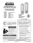
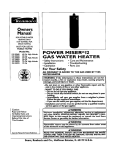
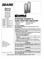
POWER
MlSER 6
GAS WATER
HEATER
• Care and Maintenance
• Troubleshooting
• Parts List
• Safety Instructions
• Installation
• Operation
For Your Safety
AN ODORANT
iS ADDED
WATER
HEATER
TO THE
GAS
USED
BY THIS
WARNING:
if the information
in these instructions are not followed exactly, a fire or explosion may result, causing property
damage, personal injury or death.
-Do not store or use gasoline or other flammable vapors and liquids
in the vicinity of this or any other appliance.
-WHAT
TO DO IF YOU SMELL GAS
• Do not try to light any appliance.
, Do not touch any electrical switch; do not use any phone in your
building.
• Immediately
call your gas supplier from a neighbor's phone.
Follow the gas supplier's instructions.
° If you can not reach your gas supplier, call the fire department.
-Installation
and service must be performed
service agency or the gas supplier.
Caution:
by a qualified installer,
Read and Follow
All Safety Rules and
Operating Instructions
Before First Use of
This Product.
AWARNING
Improper installation, adjustment, alteration, servlce or maintenance can
cause DEATH, SERIOUS BODILY INJURY, OR PROPERTY DAMAGE. Refer to
this manual for assistanceor consult the local Sears Service Center or gas utility for further nformation.
_WARNING
Flammable vapors may be drawn by air currents from other areas of the
structure to this appliance.
AWARNING
I
Save this Manual for Future Reference.
Sears, Roebuck
READ THE GENERAL SAFETY SECTION BEGINNING ON INSIDE COVER
AND THEN THIS ENTIRE MANUAL BEFORE INSTALLING OR OPERATING THIS WATER HEATER.
and Co., Hoffman
Estates,
IL 60179
U.S.A.
Safety
recautions
_WARNING
Improper installation, adjustment,
a|teration,
service or
maintenance
can cause DEATH,
SERIOUS
BODILY
INJURY, OR PROPERTY DAMAGE. Refer to this manual for assistance or consult your local Sears Service
Center for further information.
AWARNING
WATER HEATERS EQUIPPED
FOR ONE TYPE GAS
ONLY: This water heater is equipped for one type gas
only. Check the model rating plate near the gas control
valve for the correct gas. DO NOT USE THIS WATER
HEATER WITH ANY GAS OTHER THAN THE ONE
SHOWN
ON THE MODEL RATING PLATE. Failure to
use the correct gas can cause problems which can result in
DEATH, SERIOUS
BODILY INJURY, OR PROPERTY
DAMAGE. if you have any questions or doubts consult
your gas supplier or local utility.
AWARNING
INSTALLATIONS
IN AREAS WHERE FLAMMABLE LIQUIDS (VAPORS)
ARE LIKELY TO BE PRESENT
OR
STORED (GARAGES, STORAGE, AND UTILITY AREAS,
ETC): Flammable
tiquids (such as gasoline, solvents,
propane (LP) or butane, etc.), all of which emit flammable
vapors, may be improperly stored or used in such areas.
The gas water heater pilot light or main burner can ignite
such vapors. The resulting flashback and fire can cause
death or serious burns to anyone in the area, as well as
property damage.
If installation in such areas is your only option, then the
installation must be accomplished in a way that the pilot
flame and main burner flame are elevated from the floor
_t least 18 inches. While this may reduce the chances of
flammable vapors from a floor spill being ignited, gasoline
and other flammable substances should never be stored or
used in the same room or area containing a gas water
heater or other open flame or spark producing appliance.
NOTE: Flammable vapors may be drawn by air currents
from other areas of the structure to the appliance.
_WARNING
If this water heater will be used in beauty shops, barber
shops, cleaning establishments, or self-service laundries
with dry cleaning equipment, it is imperative that the
water heater or water heaters be installed so that combustion and ventilation air be taken from outside these
areas. Refer to the "Locating The New Water Heater"
section of this manual and also the latest edition of the
National Fuel Gas Code, ANS! Z223.1, also referred to as
NFPA 54 for specifics provided concerning air required.
_WARNING
At the time of manufacture
this water heater was provided with a combination temperature-pressures
relief
valve certified by a nationally recognized testing laboratory that maintains periodic inspection of production of
listed equipment or materials, as meeting the requirements for Relief Valves and Automatic
Gas Shutoff
Devices for Hot Water Supply Systems, and the latest
edition of ANSI Z21.22 and the code requirements
of
ASME. If replaced,
the valve must meet the requirements of local codes, but not less than a combination
temperature and pressure relief valve certified as meeting the requirements
for Relief Valves and Automatic
Gas Shutoff Devices for Hot Water Supply Systems,
ANSI Z21.22 by a nationally recognized testing laboratory that maintains periodic inspection of production of
listed equipment or materials.
The valve must be marked with a maximum set pressure
not to exceed the marked hydrostatic working pressure
of the water heater (I 50 Ibs./sq. in.) and a discharge
capacity not less than the water heater input rate as
shown on the model rating plate. (Electric heaters watts divided by 1000 x 3415 equal BTU/Hr. rate.)
Your local jurisdictional authorlty_ while mandating the
use of a temperature-pressure
relief valve complying
with ANSI Z21.22 and ASME, may require a valve model
different from the one furnished with the water heater.
Compliance with such local requirements
must be satisfied by the installer or end user of the water heater with
a locally prescribed temperature-pressure
relief valve
installed in the designated opening in the water heater in
_lace of the factory furnished valve.
For safe operation of the water heater, the relief valve
must not be removed from it's designated opening or
plugged.
The temperature-pressure
relief valve must be installed
directly into the fitting of the water heater designated for
the relief valve. Position the valve downward and provide
tubing so that any discharge will exit only within 6 inches
above, or at any distance below the structural floor. Be
certain that no contact is made with any live electrical
part. The discharge opening must not be blocked or
reduced
in size under any circumstances.
Excessive
length, over 30 feet, or use of more than four elbows can
cause restriction
and reduce the discharge capacity of
the valve.
No valve or other obstruction is to be placed between
the relief valve and the tank. Do not connect tubing
directly to discharge drain unless a 6" air gap is provided.
To prevent bodily injury, hazard to llfe, or property damage, the relief valve must be allowed to discharge water
in quantities should circumstances demand, if the discharge pipe is not connected to a drain or other suitable
means, the water flow may cause property damage.
The Discharge Pipe:
• Must not be smaller in size than the outlet pipe size of
the valve, or have any reducing
couplings or other
restrictions.
• Must not be plugged or blocked.
• Must be of material listed for hot water distribution.
• Must be installed so as to allow complete drainage of
both the temperature-pressure
relief valve, and the_"
AWARNING
A fire can start if combustible materials such as clothing,
cleaning materials, or flammable liquids are placed against
or next to the water heater.
• Must terminate at an adequate drain.
• discharge
Must not have
pipe. any valve between the relief valve and I
tank.
Safety
Precautions
AWARNING
_,WARNING
A gas water heater cannot operate properly without the
correct amount of air for combustion. Do not install in a
confined area such a closet, unless you provide air as
shown in the "Locating The New Water Heater" section.
Never obstruct the flow of ventilation air. If you have any
doubts or questions at all, call your gas company. Failure
to provide the proper amount of combustion air can result
in a fire or explosion and can cause DEATH, SERIOUS
BODILY INJURY, OR PROPERTY DAMAGE.
This water heater must not be installed directly on carpeting. Carpeting must be protected by a metal or wood
panel beneath the appliance extending beyond the full
width and depth of the appliance by at least 3 inches
(76.2mm) in any direction, or if the appliance is installed
in an alcove or closet, the entire floor must be covered by
the panel. Failure to heed this warning may result in a
fire hazard.
&WARNING
_WARNING
VENT DAMPERS - Any vent damper, whether it is operated thermally or otherwise must be removed if its use
inhibits proper drafting of the water heater.
Thermally
Operated Vent Dampers: Gas-fired water
heaters having thermal efficiency in excess of 80% may
produce a relatively low flue gas temperature. Such temperatures may not be high enough to properly open thermally operated vent dampers. This would cause spillage of
flue gases and may cause carbon monoxide poisoning.
Vent dampers must bear evidence of certification as complying with the latest edition of American
National
Standard ANSI Z21.68 (ANSI Z21.66 & 67, respectively,
cover electrically
and mechanically
actuated
vent
dampers). Before installation of any vent damper, consult
your local Sears Service Center or the gas utility for further information.
HOTTER
WATER CAN SCALD: Water heaters are
intended to produce hot water. Water heated to a temperature which will satisfy clothes washing, dish washing,
and other sanitizing needs can scald and permanently
injure you upon contact. Some people are more likely to
be permanently injured by hot water than others. These
include the elderly, children, the infirm, or physically/mentally handicapped. If anyone using hot water in your home
fits into one of these groups or if there is a local code or
state law requiring a certain temperature water at the hot
water tap, then you must take special precautions. In addition to using the lowest possible temperature setting that
satisfies your hot water needs, a means such as a mixing
valve, should be used at the hot water taps used by these
oeople or at the water heater. Mixing valves are available
: plumbing supply or hardware stores. Follow manuFac.urers instructions for installation of the valves. Before
l "Temperature
changing the factory
settingsection
on thein thermostat,
Regulation"
this manual. read the
AWARNING
• The appliance and its individual shutoff valve must be disconnected from the gas supply piping system during any
pressure testing of the gas system at test pressures in
excess of I/2 pound per square inch (3.SEPa).
• The appliance must be isolated from the gas supply piping system by closing its individual manual shutoff valve
during any pressure testing of the gas supply piping system at test pressures equal or less than I/2 pound per
square inch (3.5kPa),
AWARNING
Soot build-up indicates a problem that requires correction before further use. Turn "off" gas to water heater
and leave "off" until repairs are made, because Failure to
correct the cause of the sooting can result in a fire or
explosion causing DEATH, SERIOUS BODILY INJURY,
OR PROPERTY DAMAGE.
I
_,WARNING
_WARNING
Chemical vapor corrosion of the flue and vent system
may occur if air for combustion contains certain chemical
vapors. Spray can propellants, cleaning solvents_ refrigerator and air conditioner
refrigerants,
swimming pool
chemicals, calcium and sodium chloride, waxes, bleach,
and process chemicals are typical compounds which are
potentially corrosive.
BEFORE LIGHTING
[PROPANE
(L.P.) GAS WATER
HEATERS]: Propane (LR) gas is heavier than air. Should
there be a leak in the system, the gas will settle near the
ground. Basements, crawl spaces, skirted areas under
mobile homes (even when ventilated), closets and areas
below ground level will serve as pockets for the accumulation of this gas. Before attempting to light or rellght the
water heater's pilot or turning on a nearby electrical light
switch, be absolutely sure there is no accumulated gas in
the area. Search for odor of gas by sniffing at ground level
......the vicinity of the appliance. If odor is detected, follow
_eps ndicated at "For Your Safety" on the cover page of
this manual then leave the premises.
Obstructed or deteriorated vent systems may present a
t
serious health risk or AWARNING
asphyxiation.
Safety
3
Precautions
continued
on page 4
Safety
Precautions
_CAUTION
AWARNING
WATER HEATERS EVENTUALLY
LEAK: Installation ol
the water heater must be accomplished in such a manner
that if the tank or any connections should leak, the flow of
water will not cause damage to the structure. When such
locations cannot be avoided, a suitable drain pan should
be installed under the water heater. Drain pans are available at your local Sears store. Such a drain pan must be
not greater than I |/2 inches deep, have a minimum
length and width of at least 2 inches greater than the
water heater dimensions and must be piped to an adequate drain. The pan must not restrict combustion air
flow. Under no circumstances
is the manufacturer
or
Sears to be held liable for any water damage in connection with this water heater.
The water heater with draft hood installed must be properly vented to a chimney which terminates
outdoors.
Never operate the water heater unless it is vented to the
outdoors and has adequate air supply to avoid risks of
improper operation, explosion or asphyxiation.
_WARNING
Hinlmum clearances between the water beater and combustible construction are I" at the sides and rear, 4" at the
front, and 6" from the vent pipe. Clearance from the top of the
jacket is 18" on most models. Note that a lesser dimension may
be allowed on some models. Refer to the label on the water
heater adjacent to the gascontrol valve for all clearances.
I
,_WARNING
Do not use this appliance if any part of it has been under
water. Immediately
call a Sears Service Technician to
inspect the appliance and to replace the gas control or any
part of the burner system which has been under water.
AWARNING
HYDROGEN GAS: Hydrogen gas can be produced in a hot
water system that has not been used for a long period of
time (generally two weeks or more). Hydrogen gas is
extremely flammable and explosive. To prevent the possibUity of injury under these conditions_ we recommend the
hot water faucet be opened for several minutes at the
kitchen sink before any electrical appliances which are
connected to the hot water system are used (such as a dis_washer or washing machine). If hydrogen gas is present,
there will probably be an unusual sound similar to air
escaping through the pipe as the hot water faucet is
opened. There must be no smoking or open flame near
the faucet at the time it is open.
_WARNING
INSULATING
JACKETS: When installing an external
water heater insulation jacket on a gas water heater:
• DO NOT cover the temperature-pressure
relief valve.
• DO NOT put insulation over any part of the top of the
gas water heater.
• DO NOT put insulation over the gas control valve or gas
control valve/burner cover, or any access areas to the
burner.
• DO NOT let insulation around the gas water heater to
get within 8 inches of the floor (air must get to the
burner).
• DO NOT cover or remove operating instructions, and
safety related warning labels and materials affixed to the
water heater.
Failure to heed this will result in the possibility of a fire or
explosion.
t
I
I
I
I
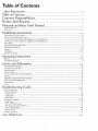
Table
of Contents
_al_y¢_'_"
Precautions ............................................................................................................................................
24
Table of Contents .......................................................................................................
5
Customer
Responsibilities
....................................................................................................
6
Product Specifications .....................................................................................................
6
Materials and Basic Tools Needed ................................................................................
7
Materi_s Needed ......................................................................................................................................................................
Basic Tools ................................................................................................................................................................................
7
7
Installation Instructions ..................................................................................................
8-16
Removing the Old \Vater Heater ...............................................................................................................................................
8
Facts to Consider About the Location .......................................................................................................................................
9
Combustion Air and Ventilation for Appliances in Unconfined Spaces ...................................................................................
10
Combustion Air and Ventilation for Appliances in Confined Spaces .......................................................................................
10
Water Piping ...........................................................................................................................................................................
t1
Temperature-Pressure Relief Valve...........................................................................................................................................
12
Filling the Water Heater ..........................................................................................................................................................
13
Venting ..............................................................................................................................................................................
13-14
Gas Piping .........................................................................................................................................................................
14-15
Installation Checklist ..............................................................................................................................................................
16
OperatinR Instructions
.........................................................................................................................
I7-19
Eighting .............................................................................................................................................................................
Temperature Regulation ..........................................................................................................................................................
_ervice and Adjustment
......................................................................................................................
Tank (Sediment) Cleaning ......................................................................................................................................................
Venting System Inspection ......................................................................................................................................................
Burner Inspection ...................................................................................................................................................................
Burner Cleaning .....................................................................................................................................................................
L.P. Gas Control Valve & Burner Assembly ............................................................................................................................
Draining .................................................................................................................................................................................
Temperature-Pressure Relief Valve Operation ..........................................................................................................................
Drain VaJveWasher Replacement ...........................................................................................................................................
Housekeeping .........................................................................................................................................................................
Service ....................................................................................................................................................................................
17-!8
19
20-21
20
20
20
20
20
21
21
21
2!
21
Troubleshooting Guide ..............................................................................................
22-25
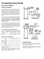
Start Up Conditions ..........................................................................................................................................................
Thermal F_xpansion ..............................................................................................................................................................
Strange Sounds .....................................................................................................................................................................
Condensation .......................................................................................................................................................................
Smoke/Odor .........................................................................................................................................................................
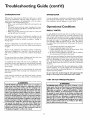
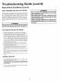
Operational Conditions .....................................................................................................................................................
Smelly Water ........................................................................................................................................................................
"Air" in Hot \rater Faucets ...................................................................................................................................................
High Temperature Shut Off System ......................................................................................................................................
Not Enough Hot Water ........................................................................................................................................................
Water is too Hot ...................................................................................................................................................................
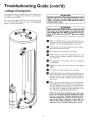
.... Leakage Checkpoints ..............................................................................................................................................................
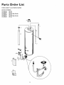
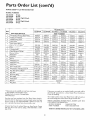
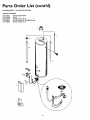
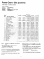
tarts Order List ...............................................................................................................................................
22-23
22
22
23
23
23-24
23
23
24
24
24
25
28-31
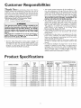
Customer
ponsibilities
,-,-ILlnanK
You for purchasing a Sears water heater.
Properly installed and maintained, it should give you years of
trouble free service. If you should decide that you want the new
water heater professionally installed by Sears call the local Sears
Service Center or aW Sears store. They will arrange for prompt,
quality installation by Sears authorized contractors.
Abbreviations Found In This Instruction Manual
A.G.A. - American Gas Association
A.N.S.L -American National Standards Institute
AWARNING
This gas-fired water heater is design certified by the
American Gas Association Laboratories under American
National Standards for Gas Water Heaters, The installation must conform with this manual, Local Codes and with
the latest edition of the National Fuel Gas Code, ANS!
Z223. I.
This publicationis availablefrom your localgovernment or
public library, gas company, or by writing NFPA,
Batterymarch Park, Quincy,MA 02269.
• Read the "Safety Precautions" section, pages 2 through 4 of
this manual first and then the entire manual carefnll)_ If you
don't follow the safety rules, the water heater will not operate
properly. It could cause DEATH, SERIOUS BODILY
INJURY AND/OR PROPERTY DAMAGE.
roduct
MODEL
NUMBER
153.336150
153.336250
153.33631i
153.336350
153.336411
153.336450
153.336511
153.336550
153.336750
153.336811
153.336850
• This manual contains instructions for the installation, op£
tion, and maintenance of the gas-fired water heater. It also
contains warnings through out tile manual that you must read
and be aware of, All warnings and ali instructions are essential
to the proper operation of the water heater and your safety.
Since we cannot put everything on the first few pages, READ
THE ENTIRE MANUAL BEFORE ATTEMPTING TO
INSTALL OR OPERATE THE WATER HEATER.
• The installation must confbrm with the instructions in this
manual; gas company rules; and Local Codes, or in the
absence of Local Codes, with the latest edition of the National
Fuel Gas code, ANSI Z223.1, also referred to as NFPA 54.
This publication is available from your local government or
public library or gas company or by writing NFPA,
gatterymarch Park, Quincy, MA 02269.
• If after reading this manual you have any questions or do not
understand any portion of the instructions, call the Sears
Service Center.
• Carefillly plan the place where you are going to put the water
heater. Correct combustion, vent action, mad vent pipe installation are very important in preventing death from possible
carbon monoxide poisoning and fires.
Examine the location to ensure the water heater complies with
the "Facts to Consider About the Location" section in this
manual,
o For California installation this water heater must be braced,
anchored, or strapped to avoid falling or moving during an
earthquake. See instructions for correct installation procedures. Instructions may be obtained from your local dealer,
wholesaler, public utilities or California Office of the State
Architect, 400 P Street, Sacramento, CA 95814.
Specifications
'lANK
CAPACITY
IN GALLONS
30
40
30
30
40
40
50
50
30
40
40
TYPE
OF
GAS
NATURAL
NATURAL
NATURAL
NATURAL
NATURAL
NATURAL
NATURAL
NATURAL
PROPANE (L.P,
PROPANE (L.P.)
PROPANE (L.P.)
B.ZU.
RATE
30,000
35,000
33,500
33,500
35,500
35,500
35,5OO
35,500
33,500
35,500
35,50O
RECOVERY
RATEGALS.
PER HOUR @
90°F RISE
30,7
35.8
34.3
34.3
36.3
36.3
36.3
36.3
34.3
36.3
36.3
MINIMUM
VENT
PIPE
3" or 4"
3" or 4"
3"
3"
3"
3"
3"
3"
3"
3"
3"
DIMENSIONSININCHES
HEIGHTTO
DIAMETER
18
2O
16
16
18
t8
20
20
16
t8
t8
JACKETTOP
47
47_
56
56
56_
56_
56_
56_
56
56_
56_
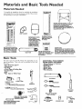
ateriais
Materials
and Basic Tools Needed
Needed
To simplify the installation Sears has available the installation
parts shown below. You may or may not need
als, depending
on your type of installation.
Water Heater
Installation
i Kit
all of these
materi-
WATER HEATER STAND 24"x24"x18"
FOR USE WITH WATER HEATERS
INSTALLED IN RESIDENTIAL
GARAGES HAVING A DIAMETER 24"
OR LESS AND A RATED CAPACITY 75
GALLONS OR LESS
O
_i
_i
VENT
ELBOW
EXPANSION
TANKS
FOR THERMAL
EXPANSION
CONDITIONS AVAILABLE IN
2 GALLON AND 5
GALLON CAPACITY
THROUGH
LOCAL
SEARS STORE OR
SERVICE CENTERS
WATER HEATER INSTALLATION KIT WITH FLEXIBLE CONNECTORS
FOR
314" OR 1/2" THREADED
OR COPPER PLUMBING
k
VENT
PIPE
FLEXIBLE WATER
HEATER GAS CONNECTOR WITH
FITTINGS
WATER HEATER H EAT
TRAPS HELP REDUCE HEAT
LOSS DUE TO THERMAL
SYPHONING
DRAIN PANS
AVAILABLE IN 20" DIAMETER FOR
WATER HEATERS HAVING A DIAMETER 18" OR LESS AND AVAILABLE IN
28" DIAMETER FOR WATER HEATERS
HAVING A DIAMETER 26" OR LESS
Basic Tools
You may or may not need
type of installation.
These
Sears store.
all of these tools, depending
on your
tools can be purchased
at your locaI
• Pipe Wrenches (2) 14"
• Screwdriver
• Tin Snips
• 6 Foot Tape of Folding Rule
• Garden Hose
• Drill
° Pipe dope or Teflon Tape
ADDITIONAL
TOOLS NEEDED
WHEN SWEAT SOLDERING
• Tubing Cutters or Hacksaw
• Propane Torch
• So_ Solder
• Solder Flux
• EmeryCloth
• Wire Brushes
HACKSAW
GARDEN
HOSE
6 FOOT TAPE
PiPE
WRENCH
SLOT-HEAD
314" WIRE BRUSH
SCREWDRIVER
112" WIRE BRUSH
PHiLLiPS
SCREWDRIVER
PROPANE
TORCH
TIN SNIPS
ROLL OF LEAD FREE
SOFT SOLDER
ROLL OF TEFLON TAPE
(USE ONLY ON WATER
CONNECTIONS)
PIPE DOPE (SQUEEZE TUBE)
(USE FOR WATER AND
GAS CONNECTIONS)
ROLL OF EMERY
CLOTH
SOLDER FLUX
TUBING
CUTTER
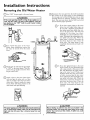
Installation
Removing
Instructions
the Old Water
Heater
Turn "OFF" the gas supply to the water heater,
_WARNING
If the main gas line shutoff serving all gas appliances is
used,also shut "OFF" the gasat each appliance. Leaveall
gas appliancesshut "OFF" until the water heater installation iscomplete.
Disconnect the vent pipe from the draft hood where
they connect to the water heater. In most installations
the vent pipe can be lifted off after any screw or other
attached devices are removed. Dispose of the draft
hood. The new water heater has the draft hood which
must be used for proper operation.
a.
Turn "OFF" the water to the water
heater, Some installations require that
the water be turned off to the entire
house.
('_Check
again to make sure the gas supply
connect the gas supply connection from
the gas control valve, "
_Jis
OFF to the water heater. Then dis-
__
A
Attach a hose to the water heater drain
valve and put the other end in a floor
drain or outdoors. Open the water heater
drain valve. Open a nearby hot water
_ucet which will relieve pressure in the
water heater and speed draining.
AWARNING
I
The water passing out of the drain valve may be extremely I
hot. To avoid being scalded,make sure all connectionsare
tight and that the water flow is directed away from any
person.
If you have copper piping to the water
heater, the two copper water pipes can
be cut with a hacksaw approximately
four inches away from where they connect to the water heater, This will avoid
cutting
off the pipes too short.
Additional cuts can be made later if necessary. Disconnect the temperature-pres_
sure retief valve drain line. When the
water heater is drained, disconnect the
hose from the drain valve. Close the
drain valve, The water beater is now
completely disconnected and ready to be
removed.
b, If you have galvanized pipe to the water
heater, loosen the two galvanized pipes
with a pipe wrench at the union in each
line. Also disconnect the piping remaining to the water heater. These pieces
should be saved since they may be needed when reconnecting the new water
heater. Disconnect the temperature_pressure relief valve drain line. When the
water heater is drained, disconnect the
hose from the drain valve. Close the
drain valve. The water heater is now
completely disconnected and ready m be
removed.
I
_CAUTION
Mineral buildup or sediment may have accumulated in the I
old water heater. This causesthe water heater to be much !
heavier than normal and this residue, if spilled out, could
causestaining.
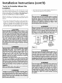
Installation
Instructions
--acts to Consider
Location
About
You should carefully
water heater, because
eration _br the safety
the most economical
not for use in mobile
(cont'd)
the
choose an indoor location for the new
the placement is a very important considof the occupants in the building and for
use of the appliance. This water heater is
homes or outdoor installation.
• The location selection must provide adequate clearances for servicing and proper operation of the water heater.
AWARNING
Whether replacing an old water heater or putting the water
heater in a new location, the following critical points must be
observed.
o The location selected should be indoors as c!ose as practical to
the gas vent or chimney to which the water heater vent is
going to be connected, and as centralized with the water piping system as possible. The water heater, as all water heaters,
will eventually leak. Do not install without adequate drainage
provisionswhere water flow will cause damage.
ACAUTION
WATER HEATERS EVENTUALLY LEAK: Installation of the
water heater must be accomplished in such a manner that if
the tank or any connections should leak, the flow of water will
not cause damage to the structure. When such locations can.
not be avoided, a suitable drain pan should be installed under
the water heater. Drain pans are available at your local Sears
store. Such a drain pan must be not greater than 1½ inches
deep, have a minimum length and width of at least 2 inches
greater than the water heater dimensions and must be piped
to an adequate drain. The pan must not restrict combustion air
flow. Under no circumstances is the manufacturer or Sears to
be held liable for any water damage in connection with this
water heater.
This water heater must not be installed directly on carpeting.
Carpeting must be protected by a metal or wood panel
beneath the appliance extending beyond the full width and
depth of the appliance by at least 3 inches (76.2mm) in any
direction, or if the appliance is installed in an alcove or closet,
the entire floor must be covered by the panel. Failure to heed
this warning may result in a fire hazard.
AWARNING
Minlmum clearances between the water heater and combustible construction are I" at the sides and rear, 4" at the
front, and 6" from the vent pipe. Clearance from the top of the
jacket is 18" on most models. Note that a lesser dimension may
be allowed on some models. Refer to the label on the water
heater adjacent to the gas control valve for all clearances.
f2" MAX.
f
VENTILATION
AIR
OPENINGS O
6'_MI_--
'11,MIN. _]_=_L]
4' HtN"
TOP VIEW
OF CLOSET
TOP VIEW I" HIN,
WITHOUT
DOOR
OF CLOSET
_;' HAX,
WITH DOOR
FRONT VI _
OF DOOR
A_R DUCT
AWARNING
INSTALLATIONS IN AREAS WHERE FLAHHABLE LIQUIDS
(VAPORS) ARE LIKELY TO BE PRESENT OR STORED
(GARAGES, STORAGE, AND UTILITY
AREAS, ETC):
Flammable liquids (such as gasoline, solvents, propane (LP) or
butane, etc.), all of which emit flammable vapors, may be
improperly stored or used in such areas. The gas water heater
pilot light or main burner can ignite suchvapors. The resulting
flashbackand fire can cause death or seriousburns to anyone in
the area, aswell as property damage.
If installation in such areas is your only option, then the installation must be accomplished in a way that the pilot flame and
main burner flame are elevated from the floor at least 18 inches.
While this may reduce the chancesof flammable vapors from a
floor spillbeing ignited, gasolineand other flammable substances
shouldnever be stored or used in the same room or area conraining a gaswater heater or other open flame or spark producing appliance.
NOTE: Flammable vapors may be drawn by air currents from
other areas of the structure to the appliance.
[
AWARNING
Propellants of aerosol sprays and volatile compounds, (cleaners, chlorine based chemicals, refrigerants, etc.) in addition to
being highly flammable in many cases, will also change to corrosive hydrochloric acid when exposed to the combustion
products of the water heater. The results can be hazardous,
and also cause product failure.
I Figure
I
AWARNING
A gas water heater cannot operate properly without the correct amount of air for combustion. Do not install in a confined
area such a closet, unlessyou provide air as shown in the "Facts
to Consider About the Location" section. Never obstruct the
flow of ventilation air. If you have any doubts or questionsat all,
call your gas company. Failure to provide the proper amount of
combustion air can result in a fire or explosion and can cause
DEATH, SERIOUS BODILY INJURY,OR PROPERTY DAHAGE.
AWARNING
If this water heater will be used in beauty shops, barber shops,
cleaning establishments, or self-service laundries with dry
cleaning equipment, it is imperative that the water heater or
water heaters be installed so that combustion and ventilation
air be taken from outside these areas. Refer to the "Facts to
Consider About the Location" section of this manual and also
the latest edition of the National Fuel Gas Code, ANSI Z223.1,
also referred to as NFPA 54 for specificsprovided concerning
air required,
i
Installation
Instructions
(cont'd)
Combustion
Air and Ventilation
for Appliances Located in
Unconfined
Spaces
Unconfined Space is a space whose volume is not less than 50
cubic feet per 1,000 Btu per hour of the aggregate input rating
of all appliances installed in that space. Rooms communicating
directly with the space in which the appliances are installed,
through openings not furnished with doors, are considered a
part of the unconfined space
In unconfined spaces in buildings, infiltration may be adequate
to provide air for combustion, ventilation and dilution of flue
gases. However, in buildings of tight construction (for example,
weather stripping, heavily insulated, caulked, vapor barrier, etc.),
additional air may need to be provided using the methods
described in Combustion Air and Ventilation for Appliances
Located in Confined Spaces, b.
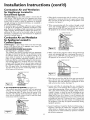
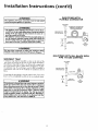
1. When directly communicating with the outdoors, each opening shall have a minimum free area of 1 square inch per 4,000
BTU per hour of total input rating of all equipment in the
enclosure. (See Figure 3.)
2. When communicating with the outdoors through vertical
ducts, each opening shall have a minimum free area of 1
square inch per 4,000 BTU per hour of total input rating of
all equipment in the enclosure. (See Figure 4.)
CHIMNEY
OFt _AS
VENT
VENTILATION
LOUVERS
(eachend o_a_tic)
Combustion Air and Ventilation
for Appliances Located in
Confined Spaces
TLET
WATER
HEATE FI
FUFtN,a.CE
Confined
Space is a space whose volume is less than 50 cubic
feet per 1,000 Btu per hour of the aggregate input rating of all
appliances installed in that space.
a. ALL AIR FROM INSIDE
BUILDINGS:
(See Page 8 Figure 1, and Figure 2 below)
The confined space shall be provided with two permanent
openings communicating
directly with an additional room(s)
of sufficient
volume so that the combined
volume of all
spaces meets the criteria for an unconfined space. The total
input of all gas utilization equipment
installed in the combined space shall be considered in making this determination.
Each opening shall have a minimum flee area of one square
inch per 1,000 BTU per hour of the total input rating of all
gas utilization equipment in the confined space, but not less
than 100 square inches. One opening shall commence within
12 inches of the top nod one commencing within 12 inches
of the bottom of the enclosure.
INLET
AJR DLFCT
a_ov_ floor_
Figure 4 ]
3. When communicating
with the outdoors through horizontal
ducts, each opening shall have a minimum
free area of !
square inch per 2,000 BTU per hour of total input rat ng oF
all equipment in the enclosure. (See Figure 5.)
_
GHIMNEY
Ofl GAS VE I
WATFFI
_
Figure
%'&
_
OUTLET
AIF_ DUCT
INLET A_F_DUCT
5 ]
8 VENT
F_RNAC.E
Ill
I Figure
4. \Vhen ducts are used, they shall be of the same cross-sectional
area as the free area of the openings to which they connect.
The minimum short side dimension of rectangular air ducts
shall not be less than 3 inches. (See Figure 5.)
OPENINGS
i _
_
2 I
,
b. ALL AIR FROM OUTDOORS:
(see Figures 3-5)
The confined space shall be provided with two permanent
openings, one commencing within 12 inches of the top and
one commencing within 12 inches f?om the bottom of the
enclosure. The openings shall communicate directly, or by
ducts, with the outdoors or spaces (crawl or attic) that freely
communicate with the outdoors.
CHIMR_
OR
GAg
V_NT
VENTILATION
LOUVER8
.
J_LT
INLETAIN
VENTILATIONLOHVENS
10
Louvers and Grilles: In calculating free area, consideration
shall be given to the blocking effect of louvers, grilles or
screens protecting openings. Screens used shall not be smaller
than 5_inch mesh. If the f?ee area through a design of louver
or grille is known, it should be used in calculating the size
opening required to provide the free area specified. If the
design and free area is not lmown, it may be assumed that
wood louvers wil! be 20-25 percent free area and metal louvers
and grilles will have 60-75 percent free area. Louvers and
grilles shall be fixed in the open position or interlocked with
the equipment so that they are opened automatically during
equipment operation.
Special Conditions Created by Mechanical Exhausting or
Fireplaces: Operation of exhaust fans, ventilation systems,
clothes dryers or fireplaces may create conditions requiring
special attention to avoid unsatisfactory operation of installed
gas utilization equipment.
Installation
'Nater
Instructions
(cont'd)
Piping
AWARNING
HOTTER WATER CAN SCALD:Water heatersare intendedto
_roducehot water. Water heatedto a temperature whichwilt
satisfyclotheswashing,dishwashing,and othersanitizingneeds
canscaldand permanentlyinjureyou upon contact.Some peopieare more likelyto be permanentlyinjuredbyhot water than
others.Theseincludethe elderly,children,the infirm,or physically/mentallyhandicapped.
If anyoneusinghot water inyourhome
fitsintooneofthesegroupsor ifthereisa localcodeor statelaw
requiring a certaintemperaturewater at the hot watertap,then
youmust take specialprecautions.
In additionto usingthe lowest
possible
temperaturesettingthat satisfies
yourhot water needs,
a meanssuchasa mixing valve,shouldbe usedat the hot water
tapsusedbythesepeopleor at the water heater.Mixingvalves
areavailableat plumbingsupplyor hardwarestores.Followmanufacturers instructionsfor installationof the valves.Before
changing the factory setting on the thermostat, read the
"Temperature Regulation"sectionin thismanual.
This water heater shall not be connected to any heating systems
or component(s)
used with a non-potable
water heating
appliance.
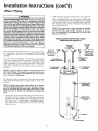
Look at the top cover of the water heater. The cold water
inlet is marked cold. Put two or three turns of teflon tape
around the threaded end of the threaded-to-sweat coupling
and around both ends of the ¾" threaded nipple. Using flexible connectors, connect the cold water pipe to the coldwater
inlet of the water heater.
NOTE: This water heater is super insulated to minimize
heat loss from the tank. Further reduction in heat loss
can be accomplished by insulating the hot water lines
from the water heater.
INSTALLATION
COMPLETED USING
SEARS INSTALLATION
KIT
SHUTOFF
VALVE
FLEXIBLE
WATER
CONNECTORS
.<....._.._
HOT OUTLET
TO HOUSE
COLD
INLET
WATER
LINE
THREADED
If a water heater is installed in a closed water supply system;
such as one having a back-flow preventer, check valve, water
aeter with a check valve, etc.., in the cold water supply; means
shall be provided to control thermal expansion, Contact the
local utilit 3,;,orlocal Sears Service Center on how to control this
situation.
THREADED
SWEAT
COUPLING
3/4" THREADED
COUPLING
TO
"_l_'_i_
TO
SWEAT
_
I
COIPLING
[
THREADED
_1---'-3f4
f__
COUPLING
NOTE: To protect against untimely corrosion of hot and
cold water fittings, it is strongly recommended that di-electrlc unions or couplings be installed on this water heater
when connected to copper pipe.
The illustration shows the attachment of the water t_iping to the
water heater. The water heater is equipped with _" water coanectlons.
i-,,I
NOTE: If using copper tubing, solder tubing to an adapter
before attadfing the adaptor to the cold water inlet connection. Do not solder the cold water supply line directly to the
cold water inlet. It will harm the dip tube and damage the
tank.
_TEHPERATUREPRESSURE
RELIEF VALVE
Look at the top cover of the water heater. The water outlet is
marked hot. Put two or three turns of teflon tape around the
threaded end of the threaded-to-sweat coupling and around
both ends of the ¾" threaded nipple. Using flexible connectors, connect the hot water pipe to the hot water outlet on
the water heater.
DISCHARGE
PIPE (Do not cap
or plug)
i6"
FLOOR
11
AIR GAP
DRAIN
installation
Temperature-Pressure
in: :ructions
(cont'd)
Relief Valve
_WARNING
AWARNING
At the time of manufacture this water heater was provided
with a combination temperature-pressures relief valve certified by a nationally recognized testing laboratory that maintains periodic inspection of production of listed equipment or
materials, as meeting the requirements for Relief Valves and
Automatic Gas Shutoff Devices for Hot Water Supply
Systems, and the latest edition of ANSI Z21.22 and the code
requirements of ASME. If replaced, the valve must meet the
requirements of local codes, but not lessthan a combination
temperature and pressure relief valve certified as meeting
the requirements for Relief Valves and Automatic Gas
Shutoff Devices for Hot Water Supply Systems, ANSI Z21.22
by a nationally recognized testing laboratory that maintains
_eriodic inspection of production of listed equipment or
materials.
The valve must be marked with a maximum set pressure not
to exceed the marked hydrostatic working pressure of the
water heater (150 Ibs./sq. in.) and a discharge capacity not
lessthan the water heater input rate as shown on the model
rating plate. (Electric heaters - watts divided by 1000 x 3415
equal BTU/Hr. rate.)
Your local jurisdictional authority, while mandating the use of
a temperature-pressure
relief valve complying with ANSI
Z21.22 and ASME, may require a valve model different from
the one furnished with the water heater.
Compliance with such local requirements must be satisfied
by the installer or end user of the water heater with a locally
)rescribed temperature-pressure relief valve installed in the
designated opening in the water heater in place of the factory furnished valve.
For safe operation of the water heater, the relief valve must
not be removed from it's designated opening or plugged.
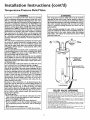
The temperature.pressure
relief valve must be installed
directly into the fitting of the water heater designated for the
relief valve. Position the valve downward and provide tubing
so that any discharge will exit only within 6 inches above, or
at any distance below the structural floor. Be certain that no
contact is made with any live electrical part. The discharge
opening must not be blocked or reduced in size under any
circumstances. Excessivelength, over 30 feet, or use of more
than four elbows can cause restriction and reduce the discharge capacity of the valve.
No valve or other obstruction is to be placed between the
relief valve and the tank. Do nut connect tubing directly to
discharge drain unless a 6" air gap is provided. To prevent
bodily injury, hazard to life, or property damage, the relief
valve must be allowed to discharge water in quantities should
circumstances demand. If the discharge pipe is not connected to a drain or other suitable means, the water flow may
cause property damage.
The Discharge Pipe:
• Must not be smaller in size than the outlet pipe size of the
valve, or have any reducing couplings or other restrictions.
• Must not be plugged or blocked.
• Must be of material listed for hot water distribution.
° Must be installed so as to allow complete drainage of both
the temperature-pressure relief valve, and the discharge
pipe.
, Must terminate at an adequate drain.
, Must not have any valve between the retlef vane and tank.
The temperature-pressure
relief valve must be manually
operated at least once a year. Caution should be taken to
ensure that (I) no one is in front of or around the outlet of
the temperature.pressure
relief valve discharge line, and (2)
the water manually discharged will not cause any bodily
injury or property damage because the water may be
extremely hot.
if after manually operating the valve, it fails to completely
reset and continues to release water, immediately close the
cold water inlet to the water heater, follow the draining
instructions, and replace the temperature-pressure
relief
valve with a new one.
COLD
HOT
SHUTOFF
VALVE
HOT
COLD
F--
T E _II_s_RUER
RELIEF
_
E-
VALVE
DISCHARGE PiPE
(Do no_cap or plug)
6"
FLOOR DP,_IN_
AIR GAP
f
RELIEFVALVEOPENING
At the time ot manufacture, this water heater was provided with a combination temperature-pressure relief vaIve listed as complyingwitl_ the standard for relief valves and
automatic gas shut-off devices for hot water supply syssems, ANSI Z2L22. For safe
operation
of thewaterheater,thereliefvalvemustnotberemoved
fromitsdesignated
point of installation or plugged.
Yourlocal
jurisdictional
authority,
while mandatingthe use ofa temperature-pressure
relief valve complying with ANSI Z2 I_22 and ASME, may require a valve model different
from the one furnished with the water heate_
Compliance with such local requirements must be satisfied by the installer or end user ....
of the water heater with a locally prescribed temperature-pressure relief valve insmlle_
in the designated opening in the water heater.
Seemanual heading -"Temperature-Pressure Relief Vafves'_for installation and maintenance of relief valve,discharge line, and other safetyprecautions,
I
I
12
installation
:illing
I
the Water
instructions
Heater
For proper venting in certain installations, a larger diameter vent
pipe may be necessary. Due to great variances in installations,
unforeseeable by the manufacturer of the water heater, you must
consult your gas company to aid you in determining the proper
venting for your water heater from the vent tables in the latest
edition of the Nationa! Fuel Gas Code ANSI Z223.1, also
referred to as NFPA 54.
ACAUTION
Never use this water heater unless it is completely filled with
water. To prevent damage to the tank, the tank must be filled
with water. Water must flow from the hot water faucet
before turning "ON"
gas to the water heater.
To fill the water heater with water:
• Close the water heater drain valve by turning the handle to
the right (clockwise). The drain valve is on the lower front of
the water heater.
• Open the cold water supply valve to the water heater.
NOTE: The cold water supply valve must be left open
when the water heater is in use.
" To insure complete _lling of the tank, allow air to exit by
opening the nearest hot water faucet, Allow water to run
until a constant flow is obtained. This will let air out of the
water heater and the piping.
• Check aHnew water piping for leaks. Repair as needed.
Check the venting system for signs of obstruction or deterioration
and replace if needed.
The combustion and ventilation air flow must not be obstructed.
AWARNING
Obstructed or deteriorated vent systems may present a serious
health riskor asphyxiation.
" Place the draft hood legs in the receiving holes on the top of
the water heater. The legs will snap in the holes to give a tight
_t.
• Place the vent pipe over the draft hood. With the vent pipe in
position, drill a small hole through both the vent pipe and
draft hood. Secure them together with a sheet metal screw.
Venting
]
(cont'd)
AWARNING
I VENT DAHPERS - Any vent damper, whether it is operated
&ermally or otherwise must be removed if its use inhibitsproper drafting of the water heater.
Thermally Operated Vent Dampers: Gas.fired water heaters
having thermal efficiency in excess of 80% may produce a relatively low flue gas temperature. Such temperatures may not be
high enough to properly
open thermally operated vent
dampers. This would cause spillage of flue gasesand may cause
carbon monoxide poisoning.
Vent dampers must bear evidence of certification as complying
with the latest edition of American National Standard ANSi
Z21.68 (ANSI Z21.66 & 67, respectively, cover electrically and
mechanically actuated vent dampers). Before installation of any
vent damper, consult your local Sears Service Center or the gas
utility for further information.
VENT_._
I
'_'
$
i
I
L
DRAFT I_O_
VENT
TO
OUTDOORS
OR
CH_x_NEY
AWARNING
The water heater with draft hood installed must be properly f
vented to a chimney which terminates outdoors. Never oper- I
ate the water heater unlessit is vented to the outdoors and has t
adequate air supplyto avoid risksof improper operation, explosionor asphyx_ion.
AWARNING
To insure proper venting of this gas.fired water heater, the
correct vent pipe diameter must be utilized. Any additions or:
deletions of other gas appliances on a common vent with this
water heater may adversely affect the operation of the water !;
heater. Consult the local Sears Service Center or gas utility if _
any such changes are planned.
l
AWARNING
The vent pipe from the water heater must be no lessthan the
I diameter of the draft hood outlet on the water heater, and
must slope upward to the chimney at least ¼ inch per linear
foot.
13
l
I
I
l
/
Installation
Venting
instructions
(cont'd)
MI vent gases must be completely
structure (dwelling). Install only
the new water heater and no other
Vent pipes must be secured at
Gas Piping
vented to the outdoors of the
the draft hood provided with
draft hood.
each joint with sheet metal
j
plate is for the purpose of input adjustment.
TO
_i
_===_
RISE PER LINEAR
FOOT
7
PIPE
&WARNING
Make sure the gas supplied is the same type listed on the
model rating plate. The inlet gas pressure must not exceed
14 inches water column ½ pound per square inch (3.5kPa).
The minimum inlet gas pressure listed on the model rating
screws.
VENT
(cont'd)
AWARNING
HIHNEY
! if the gas control valve is subjected to pressures exceeding ½
pound per square inch (33kPa), the damage to the gas contret valve could result in a fire or explosion from [ealdng gas.
INSTALLATION
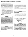
There must be a minimum of 6" clearance between single wall
vent ppi e and any combustible materia!. Fill and seal any clearance between single wall vent pipe and combustible material
with mortar mix, cement, or other noncombustible substance.
For other than single wall, follow vent pipe manufacturer's clearance specifications. To insure a tight fit of the vent pipe in a
brick chimney, seal around the vent pipe with mortar mix
cement.
AWARNING
If the main gas line shutoff serving aU gas appliances is used,
also turn "OFF" the gas at each appliance. Leave all gas appliances shut off until the water heater installation is complete.
A gas line of sufficient size must be run to the water heater.
Consult the latest edition of National Fuel Gas Code ANSI
Z223.1, also referred to as NFPA54 and the gas company con_
cernir_g pipe size.
AWARNING
Failure to have required clearances between vent piping and
combustible material will result in a fire hazard.
There must be:
• A readily accessible manual shut offwJve in the gas supply line
serving the water heater, and
• A drip leg (sediment trap) ahead of the gas control valve to help
prevent dirt and foreign materials from entering the gas control
A WARNING
Be sure vent pipe is properly connected to prevent escape of
dangerous flue gases which could cause deadly asphyxiation.
ValVe.
• A flexible gas connector or a ground joint union between the
shutoffvalve and control valve to permit servidng of the unit,
Be sure to check all the gas piping for leaks befbre lighting the
water heater. Use a soapy water solution, not a match or open
flame. Rinse offsoapy solution and wipe dry.
AWARNING
Chemical vapor corrosion of the flue and vent system may
occur if air for combustion contains certain chemical vapors.
Spray can propellants, cleaning solvents, refrigerator and air
conditioner refrigerants, swimming pool chemicals, calcium
and sodium chloride, waxes, bleach, and process chemicals are
typical compoundswhich are potentially corrosive.
Standard Models are for installation up to 3,300 feet above sea
level.
Iilgh Altitude Models are for installation from 3,300 to 5,500
feet above sea level.
Ifa standard modd is installed above 3,300 feet or a high altitude
model is installed above 5,500 feet, the input rating must be
reduced at the rate of 4 percent for each 1,000 feet above sea level.
Contact your local Sears Service Center or gas utility for further
informafioo.
14
Installation
Instructions
(cont'd)
GAS PIPING WITH
FLEXIBLE CONNECTOR
The appilance and its gas connection must be leak tested
_WARNING
J
before placing the appliance in operation.
GAS SUPPLY
PIPING
FLEXIgLE GAS CONNECTOR
LABELED AS COMPLYING
_WARNING
"The appliance and its individual shutoff valve must be disconnected from the gas supply piping system during any pressure
testing of the gas system at test pressures in excess of 9
pound per square inch (3.5kPa),
• The appliance must be isolated from the gas supplypiping sys
tern by closing its individual manual shutoff valve during any
pressure testing of the gas supply piping system at test prossuresequal or lessthan _ pound per square inch (3.5kPa).
AWARNING
Use pipe joint compound or teflon
UNION(Op_
GROUND
JOINT
WITH
ANSI
STANDING
"I -
I
CAP
tape marked as being I
resistant to the action of petroleum [Propane (L.R)] gases.
SEDIHENT
_
I
GAS PIPING WITH ALL BLACK
PIPE TO GAS CONTROL
TRAP
A sediment trap shall be installed as close to the inlet of the
rater heater as practical at the time of water heater installation.
The sediment trap shall be either a tee fitting with a capped nipple in the bottom outlet or other device recognized as an effective sediment trap. If a tee _itting is used, it shall be installed in
conformance
with one of the methods of installation
shown
GAS SUPPLY
PIPING
GROUND
JOINT
--_--_
be!ow.
Connecting the gas piping to the gas control valve of the water
heater can be accomplished by either of the two methods shown.
U NION(Optional}
T_
3" rain.
_WARNING
Contaminants in the gas lines may cause improper operation
of the gas control valve that may result in fire or explosion,
Before attaching the gas line be sure that all gas pipe is clean
on the inside. To trap any dirt or foreign material in the gas
supply line, a drip leg (sometimes called a sediment trap)
must be incorporated in the piping. The drip leg must be
readily accessible, install in accordance with the "Gas Piping"
section. Refer to the latest edition of the National Fuel Gas
Code, ANSI Z223.1, also referred to as NFPA 54.
:_
_
J
P_
]
CAP
i
15
DRIP
LEG
GAS
IRON
Installation
Instructions
installation
Checklist
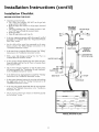
BEFORE LIGHTING
THE PILOT:
(cont'd)
Check the gas lines for leaks.
a. Use a soapy water solution. DO NOT test for gas leaks
using a match or open flame.
b. Brush the soapy water solution on all gas pipes, joints and
fittings.
c. Check for bubbling soap. This means you have a leak.
Turn "OFF" gas and make the necessary repairs.
d. Recheck for leaks.
e. Rinse offsoapysolution andwipe dry.
VENT
PiPE
OUTDOORS
TO
SHUTOFF
OR CHIHNEY
1'
• Is the new temperature-pressure relief valve properly installed
and piped to an adequate drain? See "Temperature-Pressure
Relief Valve" section.
.,_
" Are the cold and hot water lines connected to the water
heater correctly? See "\V/ater Piping" instructions in the
Installanon Instructions section,
GASSUPPLY
DRAFT
UNION
TEMPERATUREPRESSURE
HOOD
" Is the water heater completdy filled with water? See "Filling"
instructions in the "Installation Instructions" section.
RELIEF
--
* Will a water leak damageanything?
Consider About the Location section.
VALVE
See the "Facts to
SHUTOFF
VALVE
DISCHARGE
PIPE
(Do not cap or plug)
VALVE
• Is there proper clearance between the water heater and anything that might catch fire?See the "Facts to Consider About
the Location" section.
TEE
o Do you have adequate ventilation so that the water heater
will operate properly? See "Combustion Air and Ventilation"
in the "Installation Instructions" section.
i
DRIP
(Sediment
LEG "---_"
trap)
CAP ---_1
""
• Is the draft hood vent piping
proper ly secured. See .....
Vennng_
instructions in the Installation Instructions" section,
DRAIN
VALVE
-i_6"
" Is there proper clearance between the vent pipe and anything
that might catch on fire, See Venting instructions in the
"Installation Instructions" section.
FLOOR
DRAIN
o Is the vent pipe properly sloped and does the vent terminate
outdoors? See "Venting" instructions in the "InstalIation
Instructions" section.
-
Do you need m call your gas company to check the gas pipe
and its hookup?" sectiom
MODEL _U_E_
CAPACrrY
MODEL RATING PLATE
16
AIR GAP
Operating
Instructions
Lighting
_WARNING
BEFORE LIGHTING
[PROPANE
(L.R) GAS WATER
HEATERS]: Propane (LR) gas is heavier than air. Should there
be a leak in the system, the gas wil! settle near the ground.
Basements, crawl spaces, skirted areas under mobile homes
(even when ventilated), closetsand areas below ground levelwill
serve as pockets for the accumulation of this gas. Before
attempting to light or relight the water heater's pilot or turning
on a nearby electrical light switch, be absolutely sure there is no
accumulated gas in the are_ Searchfor odor of gas by sniffingat
ground level in the vicinity of the appliance. If odor is detected,
follow steps indicated at "For Your Safety" on the cover page of
this manual then leave the premises.
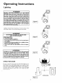
Figure 6 ]
Lighting and operating instructions are located on front of the
water heater, above or to one side of the gas control valve.
AWARNING
AN ODORANT IS ADDED TO THE GAS USED
BY THIS WATER HEATER.
FOR YOUR SAFETY
tF YOU SHELL GAS:
Figure
7 [
Do not touch any electrical switch; do not use any phone in
i your
o not
try to light any appliance.
building.
Immediately call your gas supplier from a neighbor's phone.
Follow the gas suppliers instructions.
If you cannot reach your gas supplier, call the fire department.
_, WARNING
DO NOT force the gas control knob. Use only your hand to
push it down to light the pilot, or to turn it to "ON", "OFF"
or "PILOT". Never use a tool such as a lever, wrench or pliers. Do not hit or damage the knob. A damaged knob may
result in an explosion and serious injury. If you have problem
turning the knob, call the gas supplier immediately.
CHECK
FOR
Figure 8 I
LEAKS
Be sure to check all your gas pipes for leaks before lighting your
water heater. Use a soapy water solution, not a match or open
flame. Check the factory gas fittings after pilot is lit and gas control knob is still in "PILOT" position. Then, check the fittings
when the main burner is turned "ON". Use a soapy water solution for this, too.
INNER
DOOR
......
OR .......
OUTER
I Figure 9
17
DOOR
Operating
Instructions
Lighting
label on the water
FOR YOUR
SAFETY
l
heater
(cont'd)
as it appears
READ
above
BEFORE
the thermostat
LIGHTING
WARNING
If you do not follow these instructions exactly, a fire or explosion
may result causing property damage, personal injury or loss of life.
A, This appliancehas a pilot which mustbe lighted by
hand.Whenlightingthe pilot,follow theseinstructions
exactly.
B. BEFORELIGHTINGsmellall aroundthe appliancearea
for gas. Be sure to smell next to the floor because
somegasis heavierthanair andwill settleon thefloor.
WHATTODO IF YOUSMELLGAS
• Donot tryto lightanyappliance.
• Do not touch any electric switch; do not use any
phoneinyourbuilding.
• Immediatelycatlyourgas supplierfrom a neighbor's
phone.Followthegassupplier'sinstructions.
LIGHTING
C.
O.
INSTRUCTIONS
1. STOP!Readthesafetyinformation
aboveonthis label,
2. Removeouterdoor.
3. Set the thermostat to lowest setting.by turning the
watertemperaturedial clockwise,(f "_)to its lowest
temperaturesetting(witharrowon dial)as shown.DO
9, Push in control knob all the way and hold down.
Immediately light the pilot with a match.Continueto
hold control knob in for about one (1) minuteafter
the pilot is lit. Releaseknoband it will pop back up.
Pilot shouldremainlit. If it goes out, repeat steps3
through8.
o If knobdoes not popup whenreleased,stopand
immediatelycall your service technicianor gas
supplier.
o If the pilot will not stay lit after several tries,
depressand turnthe gas controlknobclockwise
NOT FORCE,
4. Turngas controlknobclockwise_;
to "OFF" position. Knob cannotbe turned from "PILOT" to "OFF"
unlessknob is depressedslightly.DO NOT FORCE,
(Figure6, page17)
5, Wait five (5) minutesto clear out any gas. If you then
smell gas, STOP!Follow"B" in the safetyinformation
above on this label. If you don't smell gas, go to the
nextstep,
6. Remove (or open) inner door located belowthe gas
controlunit.
7. Find pilot-followmetaltube from gas control.The pilot
is locatedin front of theburner.
PILOT BURNER/1'_
®If you cannotreach your gas supplier,call the fire
department.
Useonlyyour handto pushin or turn the gas control
knob.Never use tools. If the knobwill not pushin or
turnby hand,don'ttry to repairit, call a qualified servicetechnician.Forceor attemptedrepairmay result
in a fireor explosion,
Do not use this applianceif any part has beenunder
water.Immediatelycall a qualified servicetechnician
to inspectthe applianceandto replaceanypart of the
controlsystem and any gas controlwhich has been
underwater.
_ to "OFF" and callyourservicetechnician
or gassupplier.(Figure6, page17)
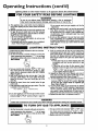
10. Replace(or close)inner door. Replaceouter door if
door does not cover gas controlon/offknob or temperatureadjustmentknob.(Figure9, page17)
11. At armslengthaway,turngascontrolknobcounterclockwise_
to thefull "ON" position.Warning
do not use gas control knob to regulate gas
flow, (Figure8, page 17)
12. At arms lengthaway,set the thermostatto desired
setting.The mark( T ) HOTindicativeof approximate
120°F is preferred starting point. Some local laws
may requirea lowerstartingpoint. If hotterwateris
desired,seeinstructionmanualand "warning" below,
13.Replacetheouterdoorifnot replacedin step10,
THERMOCOUPLE
8. Ifyou don'tsmell gas,turn knobon gascontrolcounter
clockwise_@ to "PILOT"position.(Figure7, page17)
l Hotterwater increasesthe risk of scald injury.WARNING
Beforechangingtemperature settingsee instructionmanual.
TO TURN
OFF GAS TO APPLIANCE
2. Turngascontrolknobclockwise@ 1 to "OFF" position=Knob cannotbe turnedfrom "PILOT" to "OFF"
unlessknobis depressedslightly.DO NOT FORCE,
3. Replaceouterdoor(ifremoved).
1. Set the thermostatto lowest setting by turning the
watertemperaturedial clockwise(F'-'_) to its lowest
temperaturesetting(witharrowon din0as shown.DO
NOT FORCE,
]8
Operating
Temperature
Instructions
(cont'd)
Regulation
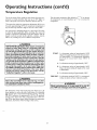
Turn the water temperature dial clockwise_f_",)
to decrease
the temperature,
or counterclockwise
(€_ -"_) to increase the
temperature.
Due to the nature of the typical gas water heater, the water tem_erature in certain situations may vary up to 30°F higher or
ower at the point of use such as, bathtubs, showers, sink, etc.
This means that when the temperature adjustment dial is set at
the mark approximating 120 ° F, the actual water temperature at
any hot water tap could be as high as 150°F or as low as 90°E
Any water heater's intended purpose is to heat water. Hot water
is needed for cleaning (bodies, dishes, clothing). HOt water will
present a scald hazard. Depending on the time element, and the
people involved (normal adults, children,
toddlers,
elderly,
infirm, etc.) scalding may occur at different temperatures.
O;
AWARNING
HOTTER WATER CAN SCALD: Water heaters are intended to
_roduce hot water, Water heated to a temperature which will
satisfyclothes washing, dishwashing,and other sanitizing needs
can scaldand permanently injure you upon contact. Some people are more likely to be permanently injured by hot water than
others. These includethe elderly, children,the infirm, or physically/mentally handicapped. If anyone usinghot water in your home
fits into one of these groupsor if there isa local code or state law
requiring a certain temperature water at the hot water tap, then
youmust take specialprecautions.In addition to usingthe lowest
_ossibletemperature setting that satisfiesyour hot water needs,
a means suchas a mixing valve,should be used at the hot water
taps used by these people or at the water heater, Mixing valves
are availableat plumbing supplyor hardware stores. Followmanufacturers instructions for installation of the valves. Before
changing the factory setting on the thermostat, read the
'_remperature Regulation" section in this manual.
1 r HOT-
ts a thermostat
setting of approximately
120°E
which will supply hot water at the most econom_
ical temperatures.
The temperature
adjustment
knob can be turned
lower than "HOT"
if
desired.
A - is a thermostat
setting of approximately
130°E
B - Is a thermostat setting of approximately 140°E
This is the lowest setting for supply of l';orwater
to dishwashers.
C - Is a thermostat
setting of approximately
150°E
VERY HOT - Is a thermostat setting of !60°E It is recommended that the dial be set lower whenever possible.
_,WARNING
Never allow small childran to use a hot water tap, or to draw
their own bath water. Never leave a child or handicapped person unattended in a bathtub or shower.
AWARNING
Should overheating occur or the gas supply fail to shut off,
turn "OFF" the manual gas control valve to the appliance.
The thermostat of this water heater has been factory set at its
lowest position, ro reduce the risk of scald injury. It is adjustable
and must be reset to the desired temperature setting. The mark
(V) HOT indicative of approximately
!20°F is the preferred
starting, point. Some states have a requirement
for a lower setring. I_you need hotter water, follow directions for temperature
adjustment, but beware of the warnings in this section.
19
Service
and Adjustment
Tank (Sediment)
Cleaning
Sediment build-up on the tank bottom may create varying
amounts of noise, and if left in the tank will cause premature
tank failure. In some water areas, you may not be able to drain
all sediment deposits by simply draining the tank. In these cases
Mag Erad (part no. 3515) can be used to help remove the sediment deposits. This may be ordered from the Sears Service
Center. For orderirlg, refer to the "Parrs Order List" section.
AWARNING
]
Soot build.up indicatesa problem that requires correction|
beforefurther use.Turn "OFF" gasto water heater and leave|
"OFF" until repairs are made, becausefailure to correctthe/
causeof the sootingcanresult in a fire or explosioncausing|
DEATH,SERIOUSBODILYINJURY,OR PROPERTYDAMAGE.|
Venting System inspection
Burner
At least once a year a visual inspection should be made of the
venting system. You should look mr:
o Obstructions which could cause improper venting. The combustion and ventilation air flow must not be obstructed.
• Damage or deterioration which could cause improper venting
or leakage of combustion products.
• Rusted flakes around top of water heater.
In the event your burner needs cleaning, use the following
instructions:
Cleaning
If inspection of the burner shows that deaning is required, turn
the gas control knob clockwise (_"_)
to the "OFF" position,
depressing slightly.
NOTE: The knob cannot be turned from "PILOT" to "OFF"
unless knob is depressed slightly. DO NOT FORCE.
AWARNING
Loose deposits on or around the burner can be removed by carefully using the hose of a vacuum cleaner inserted through the
access door of the water heater. If the burner needs to be removed
for additional cleaning, calf the Sears Service Center to remove
and clean the burner and correct the problem that required the
burner to be cleaned.
Chemical vapor corrosion of the flue and vent systemmay i
occurif air for combustioncontainscertain chemicalvapors.
Spray can propellants,cleaningsolvents,refrigerator and air
conditioner refrigerants,swlmmlng pool chemicals, calcium
and sodiumchloride,waxes,bleach,and processchemicalsare
typicalcompoundswhichare potentiallycorrosive.
L.R Gas Control Valve & Burner
Assembly Replacement
Information
AWARNING
Obstructedor deterioratedventsystemsmay present a serious
healthrisk or asphyxiation.
AWARNING
AWARNING
1Be sure the vent piping is properly connected to prevent
I escape of dangerousflue gasseswhich could causedeadly
PROPANE (L.R) GAS CONTROL VALVE AND BURNER
ASSEMBLY REPLACEMENT INFORMATION.
[asphyxiation.
For Propane (LP.) Gas Models Only:
Your water heater is equipped with a Propane (LR) gas
control valve and a main burner assemblywith left hand
threads for the following fittings and their connections.
AWARNING
if after inspectionof the vent system you found sootingor
deterioration,somethingiswrong.Call the localgasutility to
correctthe problemand cleanor replace the flue andventing
beforeresuming operationof the water heater.
(I)
The connection
between
the manifold
and the
gas control valve (A to B) are left hand threads.
(2) The connection
between the main burner orifice and the manifold
(C to D) are left hand
threads.
For ordering these replacement
parts,
please refer to the "Parts Order List" section of
this manual.
Burner Inspection
AWARNING
{
Do not usethis applianceif anypart of it hasbeen underwater.
Immediately call a Sears Service Technicianto inspectthe
appliance and to replace the gas control or any part of the
burner system which has been under water.
{
At least once a year a visual inspection should be made of the
main burner and pilor burner. The drawing is for your reference.
You should check for sooting which is not normal and wil!
impair proper combustion.
2O
Service
and Adjustment
(cont'd)
Draining
The water heater should be drained if being shut down during
freezing temperatures.
Also ,periodic draining and cleaning of
sediment from the tank may De necessary.
AWARNING
When checking the temperature.pressure relief valve operation, make sure that (1) no one is in front of or around the
outlet of the temperature-pressure relief valve discharge line,
and (2) that the water manually discharged will not cause any
property damage because the water may be extremely hot.
If after manually operating the valve, it fails to completely
reset and continues to release water, immediately close the
cold water inlet to the water heater, follow the draining
instructions, and replace the temperature-pressure
relief
valve with a new one.
" Turn the _as control knob to the "OFF" position.
• CLOSE me cold water inlet vaJve to the water heater.
• OPEN a nearby hot water faucet and leave open to allow for
draining.
° Connect a hose to the drain valve and terminate to an adequate drain.
° OPEN the water heater drain valve to allow for tank
draining.
NOTE: If the water heater is going to be shut down and
drained for an extended period, the drain valve should be
left open with hose connected allowing water to terminate
to an adequate drain.
• Close the drain valve.
° Follow instructions in the "Filling The Water Heater"
section.
• Follow the lighting instructions in the "Lighting" section to
restart the water heater.
Drain Valve Washer
Replacement
NOTE: For replacement,
use a _;_2"x _g_" x _" thick washer
available at your nearest hai'dware store. For ordering replacement washers, refer to the "Parts Order List" section.
Turn
Temperature-Pressure
Valve Operation
°
Relief
The temperature-pressure relief valve must be manually operated
at least once a year.
TEPIPERATURE.PRESSU
RE
("j_12,,
"_,r
gas supply to water heater.
Follow "Draining" instructions.
Turning counter clockwise, remove the hex cap below the
screw handle.
Remove the washer and put the new one in place.
Screw the handle and cap assembly back into the drain valve
and retighten using a wrench. DO NOT OVER TIGHTEN.
Follow instructions
in the "Filling The Water Heater"
section.
Check for leaks.
Follow rhe lighting instructions in the "Lighting" section to
restart the water heater.
HANDLE
AND CAP
;_ _" ASSEHBLY
DISCHARGE
PIPE
Failure to install and maintain a new properly listed temperature-pressure relief valve will release the manufacturer from any
claim which might resuh from excessive temperature or pressurel
Housekeeping
Vacuum around base of water heater for dust, dirt, and lint on a
regular basis.
Combustible
materials such as clothing, cleaning materials, or
flammable liquids, etc. must not be placed against or adjacent to
the water heater.
AWARNING
To insure sufficient ventilation and combustion air supply, proper clearances from the water beater must be maintained at all
times.
if the temperature=pressure
relief valve on the appliance
weeps or discharges periodically, this may be due to thermal
expansion. Your water heater may have a check valve
installed in the water line or a water meter with a check
valve. Consult the Sears Service Center for further information. Do not plug the temperature-pressure relief valve.
Service
Before calling for repair service, read the Start Up Conditions
and Operational Conditions found in the Troubleshooting
Guide of this manual.
tf a condition persists or you aze uncertain about the operation
of the water heater, let a qualified person check it out.
Contact SEARS Repair Services at 1-800-4-REPAIR
473-7247).
21
(1-800-
Troubleshooting
Start
Guide
Up Conditions
THERHAL
EXPANSION
HOT
COLD
WATER HEATER
COLD WATER
INLET FITTING
0)
EXPANSION
TANK
(_
PRESSUREGAUGE
The water within the water heater tank expands as it is heated
and increases the pressure of the water system. If the relieving
point of the water heater's temperature-pressure relief valve is
reached, the valve will relieve the excess pressure. The temperature-pressure relief valve is not intended for the constant
rdief of thermal expansion. This is an unacceptable condition
and must be corrected.
Tank Specifications
Model
]'Iknk Capacity
Dimensions in Inches
Diameter
Length
Number
[
In Gallons
WATER
SHUTOFF
RECOHMENDED INSTALLATION
(VERTICAL MOUNTING)
It is recommended
that any devices installed which could create
a closed system have a by-pass and/or the system have an expansion tank to relieve the pressure built by thermal expansion in
the water system. Expansion
tanks are available for ordering
through the Sears Service Center. Contact the local plumbing
inspector, water supplier, and/or the Sears Service Center for
assistance in controlling these situations.
Expansion
REDUCING
VALVEWITH
BY-PASS
"_Tater supply systems may, because of high line pressure, frequent cut-offs, the effects of water hammer and others, have
installed devices such as pressure reducing valves, check valves,
back flow preventers, etc. to control these types of problems.
When these devices are not equipped with an internal by-pass,
and no other measures are taken, the devices cause the water system to be closed. As water is heated, it expands (thermal expansion) and closed systems do not allow for the expansion of heated water.
Thermal
0)
PRESSURE
FLOOR, CEILING
JOIST, ETC.
WATER HEATER
COLD WATER
INLET FITTING
STRAPPING
O)
PRESSURE
REDUCING
VALVE WITH
Pipe Fitting
On Tank
BY-PASS
O)
SHUTOFF
EXPANSION
_" Male
8 inches 12_ inches
INLET COL
WATER
1! inches i14_ inches I g4 Male
PRESSURE GAUGE
Expansion
Tank Sizing
Chart
ALTERNATE RECOMMENDED
INSTALLATION
(HORIZONTAL MOUNTING)
i
] Inlet*
Water
Pressure
Expansion
Tank
i40p si
Capacity
Needed 6_ps!.
i
I
:
LT0.._P..S}
80psi
Water Heater Capacity (Gallons)
30
2
40
2
2 i 2
2
2
_[ 2
5
[- 52
2
I
66
5
5
5
7"-_5
2
5 ! 5
55
5
5
STRANGE
5.....
SOUNDS
Possible noises due to expansion and contraction of some metal
parts during periods of heat-up and cool-down do not represent
harmful or dangerous conditions.
5
5
*Highest recorded inlet water pressure m a 24 hour period or
regulated water pressure.
Condensation causes sizzling and popping with the burner area
during heat!ng and coolin,g periods and shouId be considered
normal. See Condensation section.
NOTE: Expansion tanks are pre-charged with a 40 psi air
charge. If the inlet water pressure is higher than 40 psi, the
expansion tanks air pressure must be adjusted to match that
pressure, but must not be higher than 80 psi.
22
"Froubleshooting
Guide
(cont'd)
CONDENSATION
SIOKEIODOR
Whenever the water heater is filled with cold water, a certain
amount of condensation
wil! form while the burner is on. A
water heater may appear to be leaking when in fact the water is
condensation. This usually happens when:
• When a new water heater is filled with cold water for the
first time.
• When gas burns and water vapor is produced
in water
heaters, particularly high efficiency models where flue temperatures ate lower.
, When you use large amounts of hot water in a short time
and the refill water is very cold.
It is not uncommon to experience a small amount of smoke and
odor during the initial start-up. This is due to burning off of oil
from metal parts, and will disappear in a short while.
Operational
SHELLY
Conditions
WATER
In each glasslined water heater there is installed at least one
anode rod (see parts section) for corrosion protection
of the
tank. Certain water conditions will cause a reaction between this
rod and the water. The most common complaint associated with
the anode rod is one of a "rotten egg smell". This odor is derived
from hydrogen sulfide gas dissolved in the water. The smell is
the result of four factors which must all be present for the odor
to develop:
Moisture
from the products of combustion
condense on the
cooler tank surfaces and fbrm drops of water which may fall
onto the burner or other hot surfaces to produce a "sizzling" or
"frying" noise.
Excessive condensation can cause pilot outage due to water running down the flue tube onto the main burner and putting our
the pilot.
a. a concentration
of sulfate in the supply water.
b. little or no dissolved o:cygen in the water.
c. a sulfate reducing bacteria within the water heater. (This
harmless bacteria is non-toxic to humans.)
d. an excess of active hydrogen in the tank. This is caused by
the corrosion protective action of the anode.
Because o£ the suddenness and amount of water, condensation
water may be diagnosed as a "tank leak". After the water in the
tank warms up (about 1-2 hours), the condition should disappear.
Smelly water may be eliminated or reduced in some water heater
models by replacing the anode(s) with one of less active material,
and then chlorinating
the water heater tank and all hot water
lines, Contact Sears Service for further information
concerning
an Anode Replacement
Kit #9001453
and this Chlorination
Treatment.
Do not assume the water heater is leaking until there has been
enough time for the water in the tank to warm up.
An undersized water heater will cause more condensation.
The
water heater must be sized properly to meet the family's demands
for hot water including dishwashers,
washing machines and
shower heads.
If the smdly water persists after the anode replacement and chlorination treatment, we can only suggest that continuous chlorination and filtering conditioning equipment be considered to
eliminate the water problem.
Excessive condensation may be noticed during the winter and
early spring months when incoming water temperatures are at
their lowest.
Do not remove the anode leaving the tank unprotected. By
doing so, all warranty on the water heater tank is voided.
Good venting is essentia! for a gas fired water heater to operate
properly as well as to carry away products of combustion and
water vapor.
"AIR"
A'WARNING
IN HOT WATER
FAUCETS
AWARNING
HOTTER WATER CAN SCALD: Water heaters are intended to
produce hot water. Water heated to a temperature which will
satisfyclothes washing,dish washing,and other sanitizing needs
can scaldand permanently injure you upon contact. Some people are more likelyto be permanen_ injured by hot water than
others. These include the elderly,children,the infirm, or physical.
! ly/mentatly handicapped.If anyone usinghot water in your home
fits into one of these groupsor if there is a localcode or state law
requiring a certain temperature water at the hot water tap_then
you must take specialprecautions. In addition to usingthe lowest
possibletemperature sett ng that satisfiesyour hot water needs,
_ _a means such as a mixing valve, shouldbe used at the hot water
taps used by these people or at the water heater. Mixing valves
are availableat plumbing supplyor hardware stores.Follow manufacturers instructions for installation of the valves. Before
changing the factory setting on the thermostat, read the
t 'Temperature Regulation' section in this manual.
HYDROGEN GAS: Hydrogen gas can be produced in a hot
water system that has not been used for a long period of time
(generally two weeks or more). Hydrogen gas is extremely
flammable and explosive. To prevent the possibility of injury
under these conditions, we recommend the hot water faucet
be opened for several minutes at the kitchen sink before any
electrical applianceswhich are connected to the hot water system are used (such as a dishwasher or washing machine). If
hydrogen gas is present, there will probably be an unusual
sound similar to air escapingthrough the pipe as the hot water
faucet is opened. There must be no smoking or open flame
near the faucet at the time it is open.
23
Troubleshooting
Operational
HIGH
Conditions
TEHPERATURE
SHUT
Guide
(cont'd)
OFF SYSTEH
AWARNING
Due to the nature of the typical gas water heater, the
water temperature in certain situations may be hotter
than the thermostat setting.
Short, frequent draws of hot water, especiallywith very
cold incoming water =can shockthe thermostat into brief
operation resulting in hotter and hotter layers of water
closerto the top of the tank.
Changes in hot water usage patterns or raising the temperature differential between the cut-on of the thermostat and the cold water temperature will usuaih/eliminate
the problem.
This water heater is equipped with an automatic gas shut offsystem. The high temperature shut off is built into the gas control
valve. This system shuts off the gas supply to the water heater
burners when high water temperatures are present, it is nonresettabte. If the high temperature shut off activates, the gas control valve must be replaced. If this were to occur, turn "OFF" the
entire gas supply to the water heater. Contact the Sears Service
Center.
AVVARNING
Shouldoverheating occur or the gassupplyfail to shut off,
turn "OFF" the manual gascontrol valveto the appliance,
NOT
ENOUGH
OR NO
HOT
WATER
" Check the manual gas shut offvalve to be sure it is open.
opening
behind
the outer
viewing
the models
pilot, have
i anheck
the pilot
flame.
It maydoor
havefor
gone
out. All
If the pilot is not tit, follow the "Lighting" instructions in this
marmal or located above the gas control valve on the water
heater to relight the pilot. If the water was extremely hot and
is now cold, the high limit safety temperature shut off may
have put out the burner and pilot. If the high temperature
shut off activates, the gas control valve must be replaced.
Contact the Sears Service Center.
The gas control knob must be turned to the "ON" position.
:" i_ihe temperature adjustment dial may be set too low. See the
'Ihnperature Regulation section.
• The gas company can check tile.gas input to see if it is correct.
An underfired water heater will not heat water as quickly.
• Look for leaking or open hot water faucets. Make sure dl are
dosed.
• The cold water inlet temperature may be colder during the
winter months. It will take longer to heat the water and seem
like lesshot water.
• If you canixot find what is wrong, call the Sears Service
Center,
WATER
(cont'd)
IS TOO HOT
1. The temperature adjustment dia] may be set too high. See the
"Temperature Adjustment" section.
NOTE: A period of time is necessary after an adjustment has
been made for the water temperature to reach the new temperature setting.
2. rf lower temperature settings wilI not lower the water temperature, call the SearsService Center.
24
Troubleshooting
Leakage
Guide
(cont'd)
Checkpoints
Use this guide to check a "Leaking" water heater. Many suspecr_
ed "Leakers" are not leaking tanks. Often the source of the water
can be found and corrected.
A CAUTION
Read this manual first. Then before checking the water
heater make sure the gas supply has been turned
"OFF", and never turn the gas "ON" before the tank is
completely furl of water.
If you are not thoroughly familiar with your local gas codes ),our
water heater, and safety practices, contact theSears
Service
Center to check the water heater.
A CAUTION
J
Never use this wate_it
is completely filled I
with water. To prevent damage to the tank, the tank I
must be filled with water. Water must flow from the hot I
water
faucet
before
turning
"ON"
gas to the water
heater.
Water at the draft hood is water vapor which has condensedout of the combustion products. This is caused by a
problem in the vent. Contact the Sears Service Center.
0
®
®
®
®
®
®
0
*Condensation may be seen on pipes in humid weather or
pipe connections may be leaking,
*The primary anode rod fitting may be leaking.
Small amounts of water from temperature-pressure relief
valve may be due to thermal expansion or high water pressure in your area.
*The temperature-pressure
the tank fitting.
relief valve may be leaking at
Water from a drain valve may be due to the valve opened
slightly.
*The drain valve may be leaking at the tank fitting.
Combustion products contain water vapor which can condense on the cooler surfaces of the rank. Droplets form and
drip into the fire or run on the floor. This is common at
the time of startup after installation and when incoming
water is cold.
Water in the water heater bottom or on the floor may be
from condensation, loose connections, or the relief valve.
DO NOT replace the water heater until a fial! inspection
of all possible water sources is made and necessary,corrective steps taken. Leakage from other appliances, water
lines, or ground seepage should also be checked.
NOTE: To check where threaded portion enters tank,
insert cotton swab between jacket opening and fitting.
If cotton is wet, follow "Draining" instructions in the
"Service and Adjustment _' section and then remove fitring. Put pipe dope or teflon tape on the threads and
p ace, Then follow
hlhng
the Water Heater
instructions in the "Installation Instructions" section.
25
Notes
26
Notes
27
Parts
rder
List
POWER MISER TM 6 GAS WATER HEATERS
MODEL NUMBERS:
153.336150
153.336250
153.336311
153.336350
153.336411
153.336450
30 Gal.
40 Gal.
30 Gal. High Altitude
30 Gal.
40 Gal. High Altitude
4O Gal.
160
15
14
28
Parts
POWER
MISER
rder
TM
List
(cont'd)
6 GAS WATER HEATERS
MODEL NUMBERS:
153.336150
153.336250
153.336311
153.336350
153.336411
153.336450
30
40
30
30
40
40
Gal.
Gal.
Gal. High Altitude
Gal.
Gal. High Altitude
Gal.
Model Numbers
KEY
NO.
i
2
153.336150
PART DESCRIPTION
Temperature-Pressure Relief Valve
Primary Anode Rod
3
4
Model Rating Platet
Drain Valve
5
Drain Valve Washer
('_2" x 'V_4"x _" rh!ck)**
Pilot
6
7
8
9
10
11
12
13
14
15
Thermocouple*
Pilot Tubing w/Fittings
Burner Orifice
(Drill Size)
Manifold
Burner
Manifold Cover
Manifold Cover
Inner Door
Gas Control Valve
16
Temperature Adjustment Knob
17
Dip Tube Spacer/Washer
t8 J DipTube
19
20
Restrictor Ring
Flue Baffle
21
#
Draft Hood
Manual
#
9000071
9OOO279
O27O118
9000254
9001584
900O284
42-9231
9000278
0230182
#4O
9O02615
9002411
9000358
9000281
F145-1278
F!45-I280
0530087
9001917
9000275
900O464
9000273
153.336250
__
153.336350
PART NUMBERS
9000071
9000071
9000071
9000279
0270118
9000254
9001584
9000284
42-9231
9000278
0230130
#37
9002617
9002411
9000358
9000281
Fl45-1278
F145-t280
0530087
9001918
9000275
9000300
9000273
153.336411
153.336450
9000279
0270118
9000254
9000279
0270118
9000254
9000071
9000279
0270118
9000254
9000071
9000279
0270118
9000254
9001584
9000284
42-9231
9000278
0230182
#4O (HA)
9002613
9002411
9001584
9000284
42-923I
9000278
0230130
#37
9002613
9002411
9001584
9000284
42-9231
9000278
0230138
#39 (HA)
9002615
9002411
9001584
9000284
42-9231
9000355
9000281
F145-!278
F145-1280
0530087
9001852
9000355
9000281
F145-1278
F145-1280
0530087
9001852
900O355
9000281
F145-1278
F145-t280
0530087
9002488
9002488
9000272
9000272
0291443
3515
Mag-Erad
* These parts are also available at most Seas retail stores.
** Also available at most hardware stores,
l'Replaced oniy on return of damaged plate.
# Not Illustrated
153.336311
9000278
0230141
#36
9002615
9002411
9OO0355
9000281
F145q278
9001852
F145-I280
053OO87
9001852
9002489
9000272
9002489
9000272
If the parts you need are *tot stocked locally, your order will be
electronically transmitted to a Sears Repair Parts Distribution
Center for handling.
The model number of your Gas Water Heater will be found on
the model rating plate located above the gas control valve,
Now that you have purchased your Gas Water Heater, should a
need ever exist _br repair parts or service, simply contact any Sears
Service Center or call 1-800-4-REPAIR (1-800-4-73-7247), Be
sure to provide all pertinent facts when you call or visit.
WHEN ORDERING REPMR PARTS, ALWAYS GIVE THE
FOLLO\VING INFORMATION:
MODEL NUMBER
NAME OF ITEM"
PARTFNUMBER
PART DESCRIPTION
All parts listed may be ordered from any Sears Service Center
and most Sears stores and by calling 1-800-366-PART (1-800366-7278).
THIS
29
IS A REPAIR
PAI_rS LIST, NOT A PACKING
LIST.
Parts Order
POWER MISER
TM
List (cont'd)
6 GAS WATER HEATERS
MODEL NUMBERS:
153.336511
153.336550
153.336750
153.336811
153.336850
50
50
30
40
40
Gal.
Gal.
Gal.
Gal.
Gal.
High Altitude
Propane (L.P.)
Propane (L.P.) High Altitude
Propane (LP.)
i
T
I
I
IF--
I
I
I
18
O,
2O
oi7
_O5
160
15
I4
11
//
/
%
x
'x
\
\
\
(
I
\
\
k
x
x
X
\\
30
/
/
/
/
J
/
Parts Order
_OWER
MISER
TM
6 GAS WATER
List (cont'd)
HEATERS
MODEL NUMBERS:
153.336511
153.336550
153.336750
153.336811
153.336850
50
50
30
40
40
Gal.
Gal.
Gal.
Gal.
Gal.
High A!titude
Propane (LP.)
Propane (L.R) High Altitude
Propane (L.R)
Model Numbers
KEY
NO.
1
2
3
4
5
6
7
8
Temperature-Pressure Relief Valve
PrimaryAnode Rod
Model Rating Platet
Drain Valve
Drain "VMveWasher
(_," x 1_4"x ¼"thick)**
Pilot
12
13
14
15
Gas Control Valve (See Note "A")
16
21
#
"I_mpetature Adjustment Knob
Dip Tube Spacer / Washer
Dip Tube
Restrictot Ring
Flue Baffle
Draft Hood
Manual
#
Mag-Erad
I0
11
17
18
19
20
I 153.336550 !153.336750
PAI_ DESCRIPTION
Thermocouple*
Pilot Tubing w/Fittings
Burner Orifice (See Note "A")
(Drill Size)
Manifold (See Note "A")
Burner
Manifold Cover
Manifold Cover
Inner Door
9
Note "A':
153.336511
I153.336811
1153.336850
PART NUMBERS
9000071
9000071
9000071
9000071
9000071
9000279
0270118
9000279
0270118
9000279
0270118
9000279
0270118
9000279
0270118
9000254
9000254
9000254
9000254
9000254
9001584
9000284
9001584
900o284
42-9231
9oo0278
o230141
#36
90o2617
9o0241 t
9001584
9000286
9001584
9000286
42-9231
9000278
0230224
9001584
9OOO286
42-9231
9000278
O23O138
#39 (HA)
9002617
9O02411
9000355
9000281
FI45-1278
F145-1280
42-9231
9000278
0230224
#51
9002614
9002411
0530087
9001852
9000355
9000281
F145-1278
F145-I280
0530087
9001852
9000355
9000281
FI45-I279
F145-1280
0530087
9001219
90O0272
9001219
9000272
9001218
9001852
9000272
0291443
#51 (HA)
9002616
9002411
_4a-9231
9O00278
0230225
#5O
9002616
9002411
9000355
9000281
F145-1279
F!45-I280
0530087
9001852
9000355
9000281
F145q279
F145-1280
9001219 _
9000272
9001219
9000272
0530O87
9001852
3515
For Propane (L.E) model(s) this part has left hand
threads,
If the parts you need are not stocked locally, your order will be
electronically
transmitted
to a Sears Repair Parts Distribution
Center for handling.
"
hese parts are also available
at most Sears retail' stores.
so available at most hardware stores.
tReplaced only on return of damaged plate.
# Not Illustrated
*W
The model ,umber of your Gas Water Heater will be found
the model rating plate located above the gas control valve.
on
WHEN ORDERING
REPAIR PARTS, AL\VAYS GIVE THE
FOLLO\VING
INFORMATION:
MODEL NUMBER
NAME OF ITEM
PART NUMBER
PART DESCRIPTION
Now that you have purchased your Gas grater Heater, should a
need ever exist for repair parts or service, simply contact any Sears
_qervice Center or call 1-800-4-REPAIR (t-800-4-73-7247). Be
,re to provide all pertinent _cts when you call or visit.
THIS
All parts listed may be ordered fi'om any Sears Service Center
arid most Sears stores and by calling 1-800-366-PART (1-800366-7278).
31
IS A REPAIR
PARTS LIST, NOT A PACKING
HST.
Warranty
a. Adjustingthermostat.
b. Lighting pilot.
c. Leaksin pipesor fittings.
d. Improperventing
e. Condensation
About Your Warranty
THE PRICE OF YOUR WATER HEATER DOES NOT INCLUDE
A FREE CHECKUP SERVICE CALL.On Water Heater Installations
Arranged BySears,Searswarrants the installation.
ON INSTALLATIONS NOT MADE BY SEARS AUTHORIZED
CONTRACI'ORS:
1.Your Searswarranty appliesm the product only.
2. Seatsdoes not warrant the installation.
3. A &age will be made on service calls due to poor or incomplete
installation.These include:
This manual is in non-technical language, tt may help you avoid the
cost of a needless servicecall. Many servicecalls reallyaren't needed.
Such as when:
i. The gas is turned "OFF".
2. The pilot is out.
3. A gasor water leak is due to loosepipe or connections.
FULL ONE YEARWARRANTY ON WATER HEATER
For one year from the date of purchase, when your Sears Kenmore water heater is installed and operated in accordance with the
instructions in this manual, Sears will:
1. Repair defects in material or workmanship in this water heater, free of charge.
2. Furnish and install a new current model water heater of dosest available capacity and quality, free of charge, if a leak occurs in
the rank.
LIMITED WARRANTY"ON TANKS THAT LEAK
After one year and through 6 years from the date of purchase, if a leak occurs in the tank, Sears wilt furnish a new current model
water heater of closest available capacity and qualitTg.You will be charged for installation.
LIMITED WARRANTY ON PARTS
After one year and through 3 years from the date of purchase, when your Seats Kenmore water heater is ins.tailed and operatedin
accordance with the information in this manual, if a part Failsdue to a failure in materials or workmanship, Sears willhlrmsh a
replacement part free of charge. You will be charged for labor.
If the water heater is subjected to commercial, institutional, industria! or other non-residential use (more than 2 families), the
above xv_verage
for t_s that leak is effective for 2 years from the date of purchase and the above parts warranty is effective for 1 year from the date of purchase.
To obtain warranty service, SIMPLY CONTACT THE NEAREST SEARS STOI_ OR SEARS SERVICE CENTER IN THE
UNITED STATES. This warrant}, applies only while this product is in use in the United Stares.
This warranty gives you specific legal rights and you may also have other rights which vary from state to stare.
SEARS, ROEBUCK AND CO., Dept. 817 WA, Hoffman Estates, IL 60179
Sears Installation
Warranty
In addition to any warranty extended to you on the Searsmerchandise
involved,which warranty becomeseffectivethe date the merchandiseis
installed should the workmanship of any Sears arranged installation
prove faulty within one year, Seas will, upon notice from you, cause
such faults to be correctedat no additional cost to you. If you want this
heater professionallyinstalled by Searscontact your SearsSalesperson.
They will arrange for prompt, quality installation.
Parts Ordering
Information
Sears instaHat#on Policy
All installation labor arrangedby Searsshall be performed in a neat,
workmanlikemanner in accordancewith generallyacceptedtrade practices_Further, all installationsshall comply with all !ocathws, codes
regulationsand ordinances.The customer shall also be protected, du>
ing installation,by insurancerelatingto property damage,Worker's
Compensation and Public Liability.
If you want this water heater professionallyinstalledby Searscontact
your Salesperson.They will arange for prompt, quality installation by
Searsauthorized contractors.
The model number of your gaswater heater is found on the model rating plate on the front of the water heater.
Forin-home
majorbrandrepairservice
Call24hoursa day,7 daysa week
For the repair or replacement parts youneed
delivered
directly
toyourhome
Call7 am- 7 pro,7 days a week
t -800-4-REPAIR
t -800-366-PART
(1-800-473-7247)
{1-800-366-7278)
Sears, Roebuck
and Co., Hoffman
Estates,
IL 60179
U.S.A.
0 9 44s-0f