1
,__/EARS
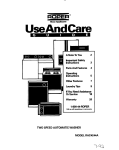
OWNER'S
MANUAL
MODEL NO.
315.108240
CAUTION:
Read Rules for
Safe Operation
and All Instructions Carefully
Thank You for Buying A
Craftsman Circular Saw
"[$
N'
7-1/4 INCH CIRCULAR
DOUBLE
SAW
INSULATED
Warranty
Introduction
Operation
Maintenance
Repair Parts
Designed excrusively for anc_sold only by
SEARS, ROEBUCK AND CO, Sears Tower, Chicago, IL 60684
®
FULL ONE YEAR WARRANTY ON CRAFTSMAN CIRCULAR SAW
if thisCraftsman Circular Saw fails to give complete satisfaction within one year from the date of purchase RETURN
IT TO THE NEAREST SEARS SERVICE CENTER I DEPARTMENT THROUGHOUT THE UNITED STATES and
Sears will repair it. tree of charge
'!
If this circular saw is used for commercial or rental purposes this warranty applies for only 90 days from the date ot
purchase
This warranty
gives you specific
legal rights, and you may also have other rights which
vary from state to state
SEARS, ROEBUCK AND CO
DEPT. 731CR-W
SEARS TOWER "
CHICAGO, IL 60684
INTRODUCTION
DOUBLE INSULATION is a concept in salely, in electric
power tools, which eliminates the need ler the usual three
wire grounded power cord and grounded supply system
Wherever there is electric current in the tool there are two
complete sets of insulation to protect the user All exposed
metal parts are isolated from inlemat metal motor components with protecting insulation
RULES
IMPORTANT - Servicing of a tool with double insulation
requires extreme care and knowledge of the system and
should be pedormed only by a qualified service technician.
For service we suggest you return the tool to your nearest
Sears store for repair. Always use original lactory replacement pads when servicing.
FOR SAFE OPERATION
READ ALL INSTRUCTIONS
1
KNOW
YOUR POWER
TOOL.
Read owneKs manual
from work area.
extension cord
carefully
Learn its applications and limilalions as well
as lhe specific potential hazards related to this tool
2
GUARD AGAINST
ELECTRICAL
VENTING BODY CONTACTWITH
FACES. For example;
erator enclosures
KEEP GUARDS
IN PLACE
STORE IDLE TOOLS. When not in use, tools should
be stored in a dry and high or locked-up place -out of
the reach of children.
SHOCK BY PREGROUNDED SUR-
pipes, radiators,
ranges, refrig-
AND IN WORKING
Cluttered
8
DON'T FORCETOOL Itwitldothe job better and saler
at the rate for which it was designed.
9
USE RIGHT TOOL, Don1 force small lool or atlachment to do the job of a heavy duty tool Don't use tool
for purpose not intended- tot example - Don't use a
circular saw for culling tree limbs or fogs.
10
DRESS PROPERLY, Do not wear loose clothing or
jewelry They can be caughl in moving parts Rubber
gloves and non-skid footwear are recommendedwhen
working outdoors. Also wear protective hair covering
to contain Iong hair
OR-
DER. Never wedge or lie lower blade guard open
Check operation of lower blade guard before each use
Do nol use if lower blade guard does not close briskty
over saw blade
WARNING:
IF SAW tS DROPPED,
LOWER BLADE GUARD MAY BE BENT, RESTRICTING FULL RETURN.
If lower blade guard becomes
bent or damaged, replace it before reuse
Do not let visitors contact lool or
4
KEEP WORK AREA CLEAN.
benches invite accidents
areas and
5
AVOID DANGEROUS ENVIRONMENT.. Don'l use
power tools in damp or wet locationsor expose to rain
Keep work area well lit
11
ALWAYS WEAR SAFETY GLASSES°
Everyday
eyeglasses have only impact-resistant lenses;theyare
NOT safety glasses
KEEP CHILDREN AND VISITORS AWAY. All visitors
shouldwear safely glasses and be kept a sale distance
12
PROTECT YOUR LUNGS, Wear a lace or dust mask
if the cutting operation is dusty
Page 2
RULES FOR SAFE OPERATION (Continued)
13
PROTECT YOUR HEARING. Wear hearing proteclion during extended periods of operation
14
DON'T ABUSE CORD. Never carry toot by cord or
yank it to disconnect from receptacle Keep cord from
heat, off, and sharp edges
15
SECURE WORK. Use clamps or a vise to hold work
Both hands are needed to operate tool
16
DON'T OVERREACH, Keep proper looting and balance at all times Do not use on a ladder or unstable
support Secure toolswhen working at elevated positions
. .
17
MAINTAIN TOOLS WITH CARE.
Keep tools sharp
and clean for better and safer pedorrnance
Follow instructions lor lubricating and changing accessories
18
DISCONNECTTOOLS,
REMOVE
ADJUSTING
20
DO NOT USE TOOL IF SWITCH D dES NOT TURN IT
ON AND OFF. Have defective switches replaced by
authorized service center
31
USE RIP FENCE. Alwaysuse
guide when ripping
atenceorstraight
32
SUPPORT
To minimize
KEYS
AND
blade
WRENCHES.
33
OUTDOOR
USE EXTENSION
CORDS.
When tool is
lot
PANELS.
always
the risk of
support
Iarge
LOWER BLADE GUARD.
WARNING:
IF LOWER
BLADE GUARD MUST BE RAISED TO MAKE A
CUT, ALWAYS RAISE IT WITH THE RETRACTING
HANDLE TO AVOID SERIOUS
18, Page 11
in
used ouldoors, use only extension cords intended
use outdoors and so marked
LARGE
pinching and kickback,
edge
panels as shown in figure 6, page 6 When cutting operation requires the resting of the saw on the workpiece, the saw should be rested on the larger podion
and the smaller piece cut oft
AVOID
ACCIDENTAL
STARTING.,
Don't carry
plugged-in tool with finger on swilch Be sure switch is
ott when plugging
21
30,
bits,
Form habit ol checking lo see that keys and adjusting
wrenches are removed from idol before turning it on
CHECK DAMAGED PARTS. Before furtheruse ol the
too!, a guard or other part that is damaged should be
carefully checked to determine that it will operate property and pedorm its intended funclion
Check for alignment of moving parts, binding ot moving pads, breakage of pads, mounting and any other conditions that
may affect its operation
A guard or other part that is
damaged should be properly repaired or replaced by
an authorized service center
When not in use, before serv-
icing, or when changing
attachments,
blades,
cutters, etc,, all tools should be disconnecled,
19.
29
34
GUARD
AGAINST
INJURY.
KICKBACK,
See Figure
Kickback
occurs
when the saw stalls rapidly and is driven back towards
the operator
Release switch immediately il blade
binds orsaw stafis Don't remove sawfrom work during
a cut while the blade is moving
See Pages 6 and 7
22
KEEP BLADES CLEAN AND SHARP.
minimize stalling and kickback
23
KEEP HANDS AWAY FROM CUTTING AREA° Keep
hands away from blades
Do not reach underneath
35
work while blade is rotating
Do not attempt to remove
cut material when blade is moving,
WARNING:
BLADES COAST AFTER TURN OFF.
BEFORE MAKING A CUT, BE SURE THE DEPTH
AND BEVEL ADJUSTMENTS
ARE TIGHT.
36
USE ONLY CORRECT BLADES° Do not use blades
with incorrect size holes Never use blade washers or
bolts that are defective or incorrect
The maximum
blade capacity of your saw is 7-1/4"
37
AVOID CUTTING
nails from lumber
38
NEVER
use
Sharp blades
24
NEVER USE IN AN EXPLOSIVE ATMOSPHERE.
Normal sparking of the motor could ignite fumes
25
INSPECT TOOL CORDS PERIODICALLY and if
damaged, have repaired by authorized service facillty
Stay constantly aware of cord location and keep it wet!
away from the rotating blade
NAILS_ Inspect
before cutting
touch the blade or other
Ior and remove
all
moving parts during
26
INSPECT EXTENSION CORDS PERIODICALLY and
replace it damaged.
39
NEVER start a tool when its rotating
contact with the workpiece
27
KEEP HANDLES DRY, CLEAN, AND FREE FROM
OIL AND GREASE, Always use a clean cloth when
cleaning Never use brake fJuids,gasoline, petroleumbased products, or any strong sofvents to clean your
too!
40
NEVER lay a loci down before its moving pads have
come to a compfete stop,
41
DO NOTOPERATE
THIS TOOL WHILE U NDER THE
INFLUENCE OF DRUGS, ALCOHOL, OR ANY MEDICATION.
STAY ALERT AND EXERCISE CONTROL° Watch
what you are doing and use common sense Do not
operate tool when you are tired Do not rush
42
SAVE THESE INSTRUCTIONS° Reler to them frequently and use themto inslructthirdpady users Ifyou
loan someone this tool, loan them these instructions
also
28.
Page 3
component
is in
FEATURES
APPLICATIONS
(Use only for the purpose Ilsted below)
1 Cutting afl types ot wood products (lumber, plywood,
paneling)
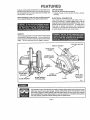
Features include easily operated bevel cut and depth of cut
adjustment mechanisms; positive 0° bevel stop; directed air
flow for keeping line of cut clear; blade wrench storage; and
lock-off switch See Figure 1.
Before attempting to use your saw, familiarize yourself
with al! operating features and safety requlrements.
ELECTRICAL
CONNECTION
Your circular saw has a precision built electric motor It
should be connected to a power supply that is 110-120
volts, 60 Hz, AC only (normal household current)° Do not
operate this tool on direct current (DC) A voltage drop of
more than 10 percent wilt cause a loss of power and
overheating 11your saw does not operate when plugged into
an outlet, double-check the power supply rating
SWITCH
Your saw is equippedwith a "lock-of!!! switch, which reduces
the possibility of accidental starling. You must depress the
button on top of the handle in orderte be able to pull the swilch
trigger The lock resets.each time tl_e trigger is released
LOCKoOFF BUTTON
SWITCH
-- UPPER
TRIGGER
BLADE
LOWER BLADE
GUARD HANDLE
BASE
ASSEMBLY
DEPTH OF CUT
ADJUSTMENT
(Wing
LOWER
Nut)
BLADE WRENCH
BLADE
BEVEL CUT
ADJUSTMENT
GUARD
BLADE WRENCH
STORAGE AREA
BLADE
(Wing
Nut)
Fig 1
The operation of any Circular Saw can result in foreign objects being thrown into your eyes,
which can result in severe eye damage. Before commencing power tool operation, always
wear safety goggles or safety glasses with side shields and a full face shIetd when needed°
We recommend Wide Vision Safety Mask for use over spectacles or standard safety glasses
with side shields, avaitable at Sears Catalog Order or Retail Stores.
Page 4
OPERATION
TO ASSEMBLE
OR REMOVE
See Figures 2 and 3,
BLADE
1, Unplug your saw.
2 Placeyoursawonapieceofscrapwoodasshowninligure3andremovebladescrew
NOTE: With blade teeth embedded
in the wood, turn blade screw counterclockwise to remove,
3. Remove spring washer and outer blade washer ("D" washer), NOTE: BLADE CAN BE REMOVED AT THIS POINT. If
you are assembling blade for the first time, or changing blades continue to follow the steps below
4, Wipe a drop ot oil onto inner blade washer and outer blade washer ("D" washer) where they contact blade.
5 Fit saw btade inside blade guard and ontospindle NOTE: The saw teeth poinl upward at the front of saw as shown in figure
2
6, Replace "D" washer and spring washer NOTE: "Cupped" side of spring washer goes against "D"washer
7 Repiace bfade screw Tighten blade screw securely NOTE, Turn blade screw clockwise to tighten
See Figure 2,
REMEMBER; NEVER USE A BLADE THAT IS TOO THICK TO ALLOW THE "D"WASHER TO ENGAGE WITH THE FLAT
ON THE SPINDLE.
BLADE
WRENCH
LOWER
BLADE
_UARD
HANDLE
SPINDLE
LOWER BLADE
BLADE
SCREW
INNER
LOWER BLADE
GUARD
BLADE
WASHER
OUTER BLADE WASHER ("D" WASHER)
OUTSIDE OF SPRING WASHER
SPRING WASHER
_
.
CUPPED SIDE AGAINST
"D" WASHER
_;._
_
BLADE WRENCH
('_
Fig 2
Page 5
BLADE SCREW
Fig3
OPERATION
SAW BLADES
The best of saw b_adeswill not cut efficiently if they are not
kept ciean, sharp, and properly set Using a dull blade will
place a heavy load on your saw and increase the danger of
kickback Keep extra blades on hand, so that sharp blades
are always available
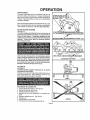
LOWER BLADE GUARD
IS IN UP POSITIO_
MAKING A CUT
Gum and wood pitch hardened onb!ade _ W[I!Slow your saw ._
down Use gum and pitch remover, hot water, or kerosene to
remove these accumulations DO NOT USE GASOLINE.
BLADE GUARD SYSTEM
See Figure 4,
The lower blade guard attached to your circular saw is
there for your protection and safety. It should never be
altered for any reason,, if It becomes damaged, do not
operate your saw until the damage has been repaired or
replaced. Always leave guard In operating position
when using your saw.
BLADE EXPOSED ON UNDERSIDE OF WORK Fig. 4
Never use saw when guard ts not operating correctly.
Guard should be checked for correct operation before
each use. NOTE: The guard Is operating correctly when
It moves freely and readily returns to the closed posltlono
If you drop your saw, cheek the lower blade guard lot
damage at all depth settings before reuse°
KICKBACK
See Figure 5.
THE BEST GUARD AGAINST KICKBACK IS TO AVOID
DANGEROUS PRACTICES.
Kickback occurs when the blade stalls rapidly and the saw is
driven back towards you Blade stalling is caused by any
action which pinches the blade in the wood
KICKBACK
1
2
3
4
5
6
7
8
IS CAUSED
BY:
incorrect blade depth setting See Figure 5.
Sawing into knots or nails in work
Twisting b_adewhile making a cut,
Making a cut with a dull, gummed up, or improperry set
blade
incorrectlysupporiing work See Figure 6
Forcing a cul
Cutting warped or wet [umber
Tool misuse or incorrect operaling procedures.
Page 6
WRONG
Fig
6
OPERATION
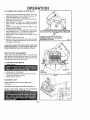
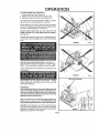
TO LESSEN
THE CHANCE
OF KICKBACK:
1 Always keep the correct blade depth setting- the correct
blade depth setting for all cuts should not exceed 1/4"
below the material to be cut See Figure 7
2 Inspect the work for knots or nails before beginning a cut
Never saw in!o a knot or nail
3 Make straight cuts Always use a straight edge guide
when rip cutting This herps prevent twisting!he blade in
the cuL
4 Nways use clean, sharp and propedy set blades Never
make cuts with dulf blades
5 To avoid pinching the blade, support the work properly
before beginning a cut The right and wrong ways to
support large pieces of work are shown in figure 6
6 When making a cut use steady, even pressure Never
force cuts
7 DO not cut warped or wet lumber
8 Always hold your saw firmly with both hands and keep
your body in a balanced position so as to resist the forces
of kickback should it occur
CORRECT BLADE DEPTH SETTING
BLADE EXPOSED I/4" OR LESS ON
UNDERSIDE OF WORK
, ,nm,nn
Fig
7
H, nl
WHEN USING YOUR SAW ALWAYS STAY ALERT AND
EXERCISE
CONTROL,
DO NOT REMOVE YOUR SAW
FROM WORKPIECE
WHILE THE BLADE IS MOVING,,
DEPTH OF CUT ADJUSTMENT
Always keep correct blade deplh setting The correct blade
depth setting for all cuts should not exceed 1/4" below the
materialto be cut More blade depth wil! increase the chance
of kickback and cause the cut to be rough
TO ADJUST BLADE DEPTH
t. Unplugyour saw.
STARTING
WING NUT
BASE
ASSEMBLY
2 Loosen wing nut See Figure 8
3. Hold base fiat against the work and raise or lower saw
until the required depth is reached
4 Tighten wing nut securely
Fig 8
=
RIGHT
A CUT
KNOW THE RIGHT WAY TO USE YOUR SAW.
See Figure 9
NEVER USE YOUR SAW AS SHOWN 1NFIGURE 10,,
NEVER PLACE YOUR HAND ON THE WORKPIECE
BEHIND YOUR SAW WHILE MAKING A CUT.
Page 7
OPERATION
TO HELP MAINTAIN CONTROL:
1
2
3
Always support your work near the cut
Suppod your work so the cut wilt be on your right
Clamp your work so it will not move during the cut
Place your work with its good side down NOTE: The good
side is the side on which appearance is important
Before beginning a cut, draw a guide line atong the desired
line of cut Then place front edge of base on that part of your
work that is solidily supported
See Figure 9
NEVER PLACE YOUR SAW ON THAT PART OF THE
WORK THAT WILL FALL OFF WHEN THE CUT IS MADE.
See Figure
1.t.
Keep the cord away from cutting area
ALWAYS place the
cord to prevent il from hanging up on the work while making
a cut
WRONG
Fig 10
WRONG
Fig 11
Hold your saw firmly with both hands. See Figure t2
Push the lock-off button and squeeze the switch trigger.
NOTE: The lock-off button is located on top of the handle
ALWAYS let the blade reach full speed, then guide your saw
into the work
LOCK-OFF BUTTON
When making a cut use steady, even pressure Forcing
causes rough cuts, could shorten the life of your saw and
could cause "kickback."
REMEMBER:
When sawing through work, the lower blade guard does
not coverthe blade, exposing it on the underside of work.
Keep your hands and fingers away from cutting area.
Any part of your body coming in contact with the moving
blade will result In serious Injury.
After you complete your cut release the trigger and allow the
blade to come to a complete stop DO NOT REMOVE YOUR
SAW FROM WORKPIECE WHILETHE BLADE IS MOVING,
CAUTION: When lifting your saw from the work the blade is
exposed on the underside of your saw until the lower bfade
guard CloSeSrMake sure lower blade guard is closed before
setting your saw down on work surtace
Page 8
RIGHT
Fig 12
OPERATION
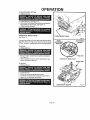
TO CROSS
CUT
OR
RIP
CUT
TOP VIEW OF SAW
When making a cross cut or rip cut, align your line of cut with
the outer blade guide notch on the saw base as shown in
figure 13 Since blade thicknesses vary, atwaysmakeatrial
cut in scrap material along a guideline to determine how
much, ii any, the guideline must be oflset to produce an
accurate cut NOTE: The distance from the line of cut to the
guideline
is the amount
FRONT OF SAW
/
you should offset the guideline
EDGE GUIDE (RIP GUIDE)
.........
Use a rip guide when making rip cuts up to five incheswide
It helps prevent the blade from twisting in a cut The blade
twisting in a cut can cause kickback, Rip Guide Cat No 927679 is available at your Sears Catalog Order or Retail
Store
TO ASSEMBLE RIP GLIIDE
1. Unplug your saw.
BLADE GUIDE
_, i INOTCH
_,__U/D
,
EL NE
ALIGN OUTER BLADE GUIDE NOTCH ON SAW
BASE WITH LINE OF CUT AS SHOWN WHEN
MAKING CROSS CUTS OR RIP CUTS
Fig. 13
2 Place rip guide throughholes in saw base as shown in
ligure 14.
3 Adjust rip guide to the length needed for the cut
4. Tighten edge guide screw securely
When using a rip guide, hold the face of the rip guide firmly
against the edge of work This makes Ior a true cut without
pinching the blade The guiding edge of work must be straight
lor your cul Io be straight Use caution to prevent the blade
lrom binding in the cut,
TO BEVEL
CUT
The angle of cul of your saw may be adjusted to any desired
setting between zero and 51,5° NOTE: When making cuts
at 515 ° blade should be set at full depth of cut, with edge
guide screw removed
PLACE RiP GUIDE
THRU HOLES
EDGE GUIDE
RIP
Fig 14
When making 45° bevel cuts, there is a notchin the saw base
to help you line up the blade with the line of cut See Figure
I5 Align your line of cut with the inner blade guide nolch on
the saw base when making 45 '_bevel cuts Since blade
thicknesses vary and different angles require different
settings, always make a trial cut In scrap material along
a guideline to determine how much you should offset the
guideline on the board to be cut.
BEVEL
ADJUSTMENT
WING NUT
When making a bevel cut hold your saw firmlywilhboth hands
as shown in figure 16 Rest the front edge of the base on the
work Push in the lock-off button and squeeze the swilch
trigger. ALWAYS let the blade reach rut{ speed, then guide
your saw intothe work
GUIDELINE
BLADE GUIDE
NOTCH
INNER BLADE GUIDE NOTCH ON SAW
BASE WITH LINE OF CUT AS SHOWN WHEN
Alter you complete your cut release the trigger and allow the
MAKING 45 _ BEVEL CUTS
Fig. 15
blade to come Ioa comp_ele stop AFTER the blade has
stopped, lilt your saw from the work
Page 9
OPERATION
TO ADJUST
I
BEVEL SETTING
Unplug your saw
2 Loosen wing nut See Figure tE,
3 Raisemotorhousingendofsawunlilyoureachdestred
angle setting on bevel scale: See-Figure 15
4, Tighten wing nut securely,
POSITIVE 0 ° BEVEL STOP
See Figure 17
LOWER BLADE GUARD
Your saw has a positive 0° bevel stop, that has been factory
adjusted to assure 0° angle of your saw blade when making
90°cuts However, misafignment can occur during shipping
BEVEL
ADJUSTMENT
WING NUT
Fig16
ADJUSTMENT
SCREW
TO CHECK
1, Unplug your saw.
2 Ptace your sawin an upside downposition onworkbench
See Figure 1_,
3 Using a carpenter's square, check squareness of saw
blade to the base of your saw
NUT
POSITIVE 0° BEVEL STOP
SAW BLADE
TO ADJUST
1 Unplug your saw
2
3
4
5
Loosen wing nut
Loosen hex nut securing adjustment screw,
Turn screw and adjust base until square with saw blade
Tighten hex nut and wing nut secureiy
CARPENTER'S SQUARE
Page10
Fig. 17
OPERATION
TO POCKET CUT
See Figure 18,
LOWER BLADE
_
_
GUARD
Adjust the bevel setting to zero and swing the lower blade
guard up using the lower btade guard handfe ALWAYS
RAISE THE LOWER BLADE GUARD WITH THE HANDLE
TO AVOID SERIOUS INJURY, WhiIe holding lower btade
guard by the handle, firmly rest the front of the base fiat
against the workpiece wit h the rear o! the handle raised so the
blade does not touch the work, See Figure 18 Push the lockoff button down and squeeze the switch trigger
E
POCKET CUT
LOWER BLADE
GUARD HANDLE
Fig.18
ALWAYS LET THE BLADE REACH FULL SPEED THEN
SLOWLY LOWER BLADE INTO THE WORK UNTIL BASE
IS FLAT AGAINST WORK_ After you comptete your cut
release the triggerand ailow the blade to come to a complete
stop. After the blade has stopped, remove it from the work
Corners may then be cleared out with a hand saw or sabre
SaW,
THE FOLLOWING RECOMMENDED ACCESSORIES ARE CLIRRENT AND WERE AVAtLABLE AT THE TIME THIS MANUAL WAS PRINTED,
Carrying Case (9-14705)
Rip Guide (9-27679)
50' 14 A W G Ext Cord (9-5821)
100' 14 AWG,
ExL Cord (9-83508)
71/4" Saw Bfade (9-32174)
7!/4" Saw Blade (9-32162)
71/4" Saw Blade (9-32122)
71/4" Saw
71/4" Saw
71/4" Saw
71t4" Saw
71t4" Saw
71t4" Saw
Blade
Blade
Blade
Blade
Blade
Blade
(9-32141)
(9-32134)
(9-32149)
(9-32526)
(9-32518)
(9_32489)
"l'heuse of attachments or accessortes not listed above might be hazardous,
Page 11
GENERAl.
Onlythe parts shown on parts list, page fitteen, are intended
to be repaired or replaced by the customer All other parts
represenl an impodantpart of tha_doubleInsulation system
and shouldbe serviced onlyby a quafified Sears service technician,,
Avoid using sofvents when cleaning plastic parts Most
plastics are susceplible to various types o! commercial solvents andmay be damaged by their use Use clean cloths to
remove dirt, carbon dust, etc,
When electric tools are used on liberglass boats, sports cars,
wallboard, spackling compounds, or piaster, it has been
found that they are subject to accelerated wear andpossible
premature failure, as the fiberglass chips and grindings are
highly abrasive to bearings, brushes, commutator, etc,
Consequently it is not recommended thatthistool be used for
extended workon any fiberglass material,wallboard, spackling
compounds, or plaster During any use on fiberglass it is
extremely important that the tool is cleaned frequently by
blowing with an airjet ALWAYS WEAR SAFETYGOGGLES,
SAFETY GLASSES WITH SIDE SHIELDS, OR A DUST
MASK DURING POWER TOOL OPERATION OR WHEN
BLOWING DUST.
LUBRICATION
All of the bearings in this tool are lubricated with a sufficient
amount of high grade lubricant for the lile of the unil under
normal operating conditions Therefore, no further lubrication is required
EXTENSION CORDS
The use of any extension cord will cause some loss of power To keep the loss to a minimum and to prevent tool overheating,
use an extension cord that is heavy enough to carry the current the tool will draw Foflow the recommended
cord sizes on the
chart provided to determine the minimum wire size required in an extension cord
Extension Cord Length
25-50 Feet
50_100 Feet
Wire Gauge Size (A,WoGo)
16
t4
When workingwith your toot outdoors, use an extension cord suitable for outdoor use and so marked Outdoor use extension
cords are marked with the letters "WA" on the cord's jacket
CAUTION: Keep extension cords away from the cutting area and posilion the cord so that it will not get caught on lumber,
lools, etc, during cutting
Ex|ension cords suitable for use with your circular saw are available at your nearest Sears Calalog Order or Retail Store
Page 12
NOTES
.............................
._l,u
lul,
.................
,ll
i,ii,,
, u ,,
lu,,,,
i i ii
i,i
in,n
_.L
Page t3
i,ill,,lll
CRAFTSMAN
CIRCULAR
SAW - MODEL NUMBER
315.108240
,
1
A" PAGE 15
29
24
13
23
22
19
Page 14
14
15
16
...........................
CRAFTSMAN
,,
CIRCULAR
SAW- MODEL NUMBER
315.108240
......................
_--
uv,,,,,,,,,
H,,
! The Model Number will be found on a plate attached Io the MotorHousing, Always mention the Model Number in all correspondenceregarding your I
! CIRCULAR SAW or when ordenng repair parts, Only the parts iistedbelow are intended to be repa{red or replaced,
SEE BACK PAGE FOR PARTS ORDERING
I
INSTRUCTIONS
H,
PARTS LIST
Key
No.
Part
Number
1
968424-001
2
Key
Part
Quan.
No.
Number
Data Plate ........................................................ 1
16
998463-001
Outer Blade Washer ....................................... 1
969:58-001
Gear and Sp_ndte............................................ 1
17
623547-002
Spnng Washer ..........................................
1
3
990147-001
Warning Tag ................................................... 1
18
612999.001
BladeScrew ........
_.......................................
4
999637-003
Bearing ........................................................... 1
19
999988-001
Label.................................................
1
5
969373-002
Lower Blade Guard Support ........................... 1
20
968425-001
Logo Plate .............................................
1
6
968702-0tl
Screw (#8-16 x 314" Pan Hd.) ......................... 7
21
967074-001
Wrench ...............................................
1
7
969827-001
22
621433-013
Logo Plate......................................................
I
Carnage Bolt (#1/4-20 x 3-114") ......................
1
8
968442-002
Fixed Blade Guard .......................................... 1
23
9
968419-002
Bumper ........................................................... 1
24
931744-059
Washer ................
_.......................................
2
10
617524-004
Screw (#10-16 x 1-3/4" Pan Hd,) .................... 1
25
621438-006
Wing Nut "'STD541625 .................................
2
11
967952-001
Torsion Spnng ................................................ 1
26
621433-091
Carnage Boil (#1/4-20 x 518"1 *'STD532507,1
12
969855-001
Lower Blade Guard Assembly ........................ 1
27
941401-815
RollPin...............................................
I
13
718602-804
Retaining Ring ................................................ 1
28
706404-607
Hex Nut (#8-32) **STD541008 ......................
1
14
999982-001
InnerBladeWasher ........................................
I
29
703432-058
Screw (#8-32 x 5/8" FiL Hd.) ........................... 1
15
""
Saw Blade 7-1/4" for 5/8" Arbor
Owner's Manual
Description
969856-001
612547-654
Oescriptlon
Quart,
Base Assembly...,i .......................................... 1
NOTE: "A'%The assembly shown represents an importanl part ol the Double Insulated System. To avoid the possibility of alteration or damage
to the system, service should be performed by you r nearest Sears Repair Center, Contact your nearest Sears Catalog Order or Retail
Store.
,
*
*"
'*"
,LVJL_
,,,,,,,,,,,, ,
Standard Hardware Item -- May Be Purchased Locally
Available From Div.98 -- Source 9B0,00
Complete Assortment Available At Your Nearest Sears Calalog Order or Retail Store
Page 15
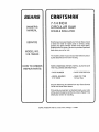
SEARS
7-1/4 INCH
CIRCULAR SAW
OWNER'S
MANUAL
DOUBLE
SERVICE
INSULATED
Now that you have purchased your Circular Saw, should
a need ever exist for repair parts or service, simply
contact any Sears Service Center and most Sears,
Roebuck and Co. stores. Be sure to provide alt pertinent
facts when you call or visiL
MODEL NO.
315.108240
The model number of you r Circular Saw will be found on
a plate attached to the motor housing.
HOW TO ORDER
REPAIR PARTS
WHEN ORDERING REPAIR PARTS, ALWAYS GIVE
THE FOLLOWING INFORMATION:
• PART NUMBER
• PART DESCRIPTION
• MODEL NUMBER
315.108240
• NAME OF ITEM
Circular Saw
A!I parts listed may be ordered from any Sears Service
Center and most Sears stores
If the parts you need are not stocked locally, your order
will be electronically transmitted to a Sears Repair Parts
Distribution Center for handling°
SEARS,
ROEBUCK
AND CO, Sears Tower, Chicago,
IL 60684