1
Installation, Operation and Maintenance Manual
IOMM ACR/AGR-1
Group: Chiller
Part Number: 074644201
Effective: March 2000
Supersedes: IOMM ACR/AGR
AIR-COOLED, RECIPROCATING, SPLIT SYSTEMS
Chiller w/ Remote Evaporator, AGR 070AM-100AM
Condensing Unit, ACR 060AS-120AS
DX Evaporators, CDE
60 Hertz, R-22
Global Chiller Line
© 1997 McQuay International
Table of Contents
Introduction.........................................3
Inspection ...........................................................3
Installation...........................................4
Handling..............................................................4
Location...............................................................5
Service Access ...................................................5
Vibration Isolators..............................................7
Water Piping .......................................................8
Flow Switch.........................................................9
Glycol Solutions...............................................10
Evaporator Flow and Pressure Drop.............11
Refrigerant Piping ............................................13
Physical Data.....................................17
Electrical Data...................................22
Field Wiring.......................................................22
AGR-AM Data..................................................23
ACR Data ..........................................................23
Electrical Notes.................................................26
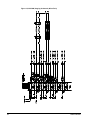
Wiring Diagrams ...............................................28
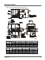
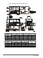
Dimensional Data..............................35
Startup ...............................................38
Pre Start-up .......................................................38
Start-Up .............................................................38
Shutdown ..........................................................38
Water Piping Checkout ...................................39
Refrigerant Piping Checkout ..........................39
Electrical Check Out.........................................40
Operation...........................................41
Hot Gas Bypass (Optional).............................41
Filter Driers........................................................41
System Adjustment..........................................42
Liquid Sightglass and Moisture Indicator...42
Refrigerant Charging .......................................42
Thermostatic Expansion Valve.......................42
Crankcase Heaters ...........................................42
DX Evaporator..................................................43
Sequence of Operation....................................43
UNT Controller, AGR-AM ...............45
General Description .........................................45
Optional Sensors..............................................45
Controller Inputs /Outputs .............................47
UNT Controller Features.................................51
Alarms ................................................................53
ZONE TERMINAL (optional) ........................53
Zone Terminal Glossary ..................................57
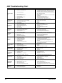
Global UNT Controller Troubleshooting
Chart...................................................................59
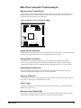
MicroTech Controller.......................61
General Description .........................................61
Optional Sensor Packages ..............................61
Installation ........................................................61
Sequence of Operation....................................70
Start-Up and Shutdown ..................................72
Keypad / Display .............................................73
Menu Descriptions..........................................76
MicroTech Controller Trouble Analysis .......87
Test Procedures................................................90
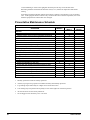
Unit Maintenance..............................97
Preventative Maintenance Schedule ............98
Service ...............................................99
Liquid Line Solenoid Valve.............................99
Evaporator.......................................................100
Refrigerant Charging .....................................100
AGR Troubleshooting Chart ........................102
Our facility is ISO 9002 Certified
"McQuay" is a registered trademark of McQuay International
1997 McQuay International
"Illustrations and data cover the McQuay International products at the time of publication and we reserve the
right to make changes in design and construction at anytime without notice"
2
IOMM ACR/AGR-1
Introduction
IMPORTANT INFORMATION
This Product Manual contains information on three different McQuay product lines.
•
Model AGR-AM This is the AGR packaged chiller but with the shell and tube
evaporator shipped loose for remote mounting. Liquid line specialties are field
supplied and mounted. Capacity control is included and is Johnson UNT as standard
or optional McQuay MicroTech Control. This unit would be the normal choice when
an indoor shell and tube water chiller and remote condensing unit with factory mounted
capacity control is desired. NOTE: AGR-AM type units are not included in the ARI
Certification Program.
•
Model ACR-AS This is an air-cooled condensing unit for use with a remote
evaporator, typically a water chiller or DX coil. Neither capacity control, liquid line
specialties, nor evaporator are included. The ACR would be the choice when a DX
coil (air handler) is used with a remote condensing unit or if some control other than
the controls available on the AGR-AM are desired. NOTE: ACR type condensing
units are not included in the ARI Certification Program.
•
Model CDE This is a DX evaporator that can be used in conjunction with the
Model ACR condensing unit. No controls or specialties are included.
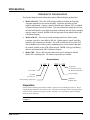
Nomenclature
A G/C R
Air-Cooled
G=Chiller
C=Cond. Unit
Reciprocating Compressor
-
XXX A S/M
Application
S= Standard Cooling
M= Remote Evaporator
Design Vintage
Model Size
Nominal Tons
Inspection
Check all items carefully against the bill of lading. Inspect all units for damage upon arrival. Report
shipping damage and file a claim with the carrier. Check the unit name plate before unloading, making
certain it agrees with the power supply available. McQuay is not responsible for physical damage
after unit leaves the factory.
Note: Unit shipping and operating weights are available in the Physical Data tables beginning
on page 17.
IOMM ACR/AGR-1
3
Installation
Note: Installation is to be performed by qualified personnel who are familiar with local codes
and regulations.
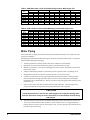
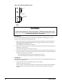
WARNING
Sharp edges and coil surfaces are a potential hazard. Avoid contact with them.
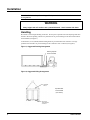
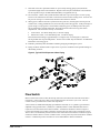
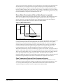
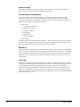
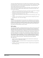
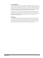
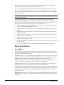
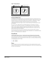
Handling
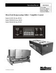
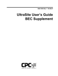
Be careful to avoid rough handling of the unit. Do not push or pull the unit from anything other than
the base. Block the pushing vehicle away from the unit to prevent damage to the sheet metal cabinet
and end frame (see Figure 1).
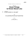
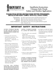
To lift the unit, 2 1/2" (64mm) diameter lifting holes are provided in the base of the unit. Arrange
spreader bars and cables to prevent damage to the condenser coils or cabinet (see Figure 2).
Figure 1, Suggested Pushing Arrangement
Blocking required
across full width
Figure 2, Suggested Lifting Arrangement
Spreader Bars
recommended
(use caution)
4
IOMM ACR/AGR-1
Location
Unit Placement
AGR-AM and ACR units are for outdoor applications and can be mounted on a roof or ground level.
Set units on a solid and level foundation. For roof mounted applications, install the unit on a steel
channel or I-beam frame to support the unit above the roof. For ground level applications, install the
unit on a substantial base that will not settle. A one piece concrete slab with footings extended below
the frost line is recommended. Be sure the foundation is level (within 1/2” [13 mm] over its length and
width). The foundation must support the operating weights listed in the Physical Data Tables.
On ground level applications protect fins against vandalism using the optional coil guards or by
erecting a screen fence. The fence must allow free flow of air to the condenser coil for proper unit
operation.
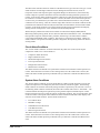
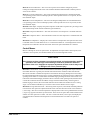
Clearances
The flow of air to and from the condenser coil must not be limited. Restricting air flow or allowing air
recirculation will result in a decrease in unit performance and efficiency. There must be no obstruction
above the unit that would deflect discharge air downward where it could be recirculated back to the
inlet of the condenser coil. The condenser fans are propeller type and will not operate with ductwork
on the fan outlet.
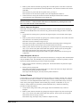
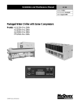
Install the unit with enough side clearance for air entrance to the coil and for servicing. Provide
service access to the evaporator, compressors, electrical control panel and piping components as
shown in Figure 3.
Do not allow debris to accumulate near the unit. Air movement may draw debris into the condenser
coil causing air starvation. Give special consideration to low ambient operation where snow can
accumulate. Keep condenser coils and fan discharge free of snow or other obstructions to permit
adequate airflow.
Sound Isolation
The ultra-low sound levels of the AGR outdoor unit and the ACR condensing unit is suitable for most
applications. When additional sound reduction is necessary, locate the unit away from sound
sensitive areas. Avoid locations beneath windows or between structures where normal operating
sounds may be objectionable. Reduce structurally transmitted sound by isolating water lines,
electrical conduit and the unit itself. Use wall sleeves and rubber isolated piping hangers to reduce
transmission of water or pump noise into occupied spaces. Use flexible electrical conduit to isolate
sound transmission through electrical conduit. Spring isolators are effective in reducing the low
amplitude sound generated by reciprocating compressors and for unit isolation in sound sensitive
areas.
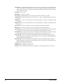
Service Access
Each end of the unit must be accessible after installation for periodic service. Compressors, filterdriers, and manual liquid line shutoff valves are accessible. The high pressure control is located in the
control panel when using the Global UNT controller, and on the compressor when using the
MicroTech controller. Low pressure, and motor protector controls are on the compressor. Most other
operational, safety and starting controls are located in the unit control box.
The condenser fan and motors can be removed from the top of the unit.
IOMM ACR/AGR-1
5
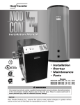
Figure 3, Clearance Requirements
Do not block the flow of air to
and from the condenser coil.
Restricting airflow or allowing
air recirculation will result in a
decrease in unit performance
and efficiency because
discharge pressures are
increased. There must be no
obstruction above the unit that
would deflect discharge air
downward where it could be
recirculated back to the inlet of
the condenser coil. The
condenser fans are propeller
type and will not operate with
ductwork on the fan outlet.
Install the unit with enough side
clearance for air entrance to the
coil and for servicing. Provide
service access to the
evaporator, compressors,
electrical control panel and
piping components. Do not
allow debris to accumulate near
the unit. Air movement may
draw debris into the condenser
coil causing coil starvation.
Give special consideration to
low ambient operation where
snow can accumulate. Keep
condenser coils and fan
discharge free of snow or other
obstructions to permit adequate
airflow for proper unit
operation.
6
IOMM ACR/AGR-1
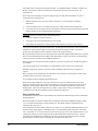
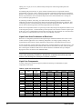
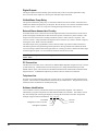
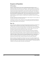
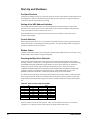
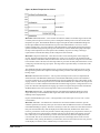
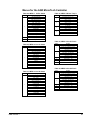
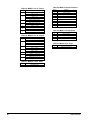
Vibration Isolators
Vibration isolators are recommended for all roof mounted installations or wherever vibration
transmission is a consideration.
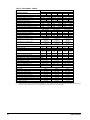
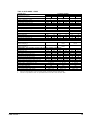
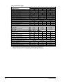
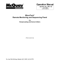
Table 1 through Table 4 list isolator point loads for all unit sizes, Figure 4 shows isolator locations.
See Dimensional Data for detailed dimensions required to secure each isolator to the mounting
surface.
The spring flex isolators are white type CP2-32, McQuay part number 047792932. A total of four per
unit is required.
Figure 4, Isolator Locations
Spring Isolator Dimensions
Table 1, AGR-AM Isolator Loads At Each Mounting Location With Aluminum Fins
AGR
Size
070
075
080
085
090
095
100
AM
AM
AM
AM
AM
AM
AM
1
2
3
4
Total Unit
kg
lb
kg
lb
kg
lb
kg
lb
kg
lb
973
1205
1265
1313
1348
1350
1351
442
547
574
596
611
613
613
1227
1471
1545
1603
1646
1649
1650
557
667
701
727
746
748
748
838
901
947
982
1008
1010
1011
380
409
429
446
457
458
459
1051
1093
1148
1191
1222
1225
1226
477
496
521
540
554
556
556
4090
4670
4905
5089
5224
5234
5238
1855
2118
2225
2308
2370
2374
2376
Table 2, ACR-A Isolator Loads At Each Mounting Location With Aluminum Fins
ACR
Size
060
065
070
075
080
090
100
110
120
IOMM ACR/AGR-1
A
A
A
A
A
A
A
A
A
1
2
3
4
lb
kg
lb
kg
lb
kg
lb
kg
867
883
891
937
1205
1265
1348
1350
1351
393
401
404
425
547
574
611
613
613
1093
1114
1124
1181
1471
1545
1646
1649
1650
496
505
510
535
667
701
746
748
748
747
761
768
807
901
947
1008
1010
1011
339
345
348
366
409
429
457
458
459
936
954
962
1011
1093
1148
1222
1225
1226
425
433
437
459
496
521
554
556
556
TOTAL UNIT
lb
kg
3642
3712
3745
3935
4670
4905
5224
5234
5238
1652
1684
1699
1785
2118
2225
2370
2374
2376
7
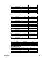
Table 3, AGR-AM Isolator Loads At Each Mounting Location With Copper Fins
AGR-AM
Size
070 AM
075 AM
080 AM
085 AM
090 AM
095 AM
100 AM
1
lb
1171
1526
1587
1634
1669
1672
1673
2
kg
531
692
720
741
757
758
759
lb
1476
1863
1937
1995
2038
2041
2042
3
kg
670
845
879
905
924
926
926
lb
1009
1142
1187
1222
1249
1250
1251
4
kg
457
518
538
554
566
567
568
lb
1264
1384
1439
1482
1514
1516
1517
TOTAL UNIT
lb
kg
4920
2232
5915
2683
6150
2790
6334
2873
6469
2934
6479
2939
6483
2941
kg
574
628
653
672
687
688
688
Table 4, ACR-A Isolator Loads At Each Mounting Location With Copper Fins
ACR
Size
060
065
070
075
080
090
100
110
120
A
A
A
A
A
A
A
A
A
1
lb
1025
1042
1089
1134
1526
1587
1669
1672
1673
2
kg
465
473
494
514
692
720
757
758
759
lb
1292
1313
1373
1430
1863
1937
2038
2041
2042
3
kg
586
596
623
648
845
879
924
926
926
lb
883
897
938
977
1142
1187
1249
1250
1251
4
kg
400
407
425
443
518
538
566
567
568
lb
1107
1125
1176
1225
1384
1439
1514
1516
1517
TOTAL UNIT
lb
kg
4307
1954
4377
1985
4575
2075
4765
2161
5915
2683
6150
2790
6469
2934
6479
2939
6483
2941
kg
502
510
533
555
628
653
687
688
688
Water Piping
Local authorities can supply the installer with the proper building and safety codes required for safe
and proper installation.
Install piping with minimum bends and changes in elevation to minimize pressure drop. Consider the
following when installing water piping:
1.
Vibration eliminators to reduce vibration and noise transmission to the building.
2.
Shutoff valves to isolate the unit from the piping system during unit servicing.
3.
Manual or automatic air vent valves at the high points of the system. Install drains at the lowest
points in the system.
4.
A means of maintaining adequate system water pressure (expansion tank or regulating valve).
5.
Temperature and pressure indicators located at the unit to aid in unit servicing.
6.
A strainer or other means of removing foreign matter from the water before it enters the pump.
Place the strainer far enough upstream to prevent cavitation at the pump inlet (consult pump
manufacturer for recommendations). The use of a strainer will prolong pump life and keep system
performance up.
7.
Place a strainer in the water line just before the inlet of the evaporator. This will help prevent
foreign material from entering and decreasing the performance of the evaporator.
CAUTION
If separate disconnect is used for the 115V supply to the evaporator heating cable,
mark the disconnect clearly to ensure disconnect is not accidentally shut off during
cold seasons.
8.
8
The shell-and-tube evaporator has a thermostat and heating cable to prevent freeze-up down to
-20°F (-29°C) that should be used if located in a sub-freezing location. It is suggested that the
heating cable be wired to a separate 110V supply circuit. All water piping to the unit must also be
protected to prevent freezing.
IOMM ACR/AGR-1
9.
If the unit is used as a replacement chiller on a previously existing piping system, flush the
system thoroughly before unit installation. Regular water analysis and chemical water treatment
for the evaporator loop is recommended immediately at equipment start-up.
10. The total water volume in the system should be sufficient to prevent frequent “on-off” cycling.
Turnover rate should not be less than 15 minutes for normal variable cooling loads. Turnover rate
for process cooling or a constant load, should not be less than 6 minutes.
11. When glycol is added to the water system for freeze protection, the refrigerant suction pressure
will be lower, cooling performance less, and water side pressure drop greater. If the percentage of
glycol is high, or if propylene is used instead of ethylene glycol, the added pressure drop and
loss of performance could be substantial. Reset the freezestat and low leaving water alarm
temperatures. The freezestat is factory set as follows:
•
UNT Control; Low Water Temp=38°F, Low Press=54psig
•
MicroTech Control; Low Water Remp=36°F, Low Press=54psig
Reset the freezestat setting to approximately 4 to 5 degrees F (2.3 to 2.8 degrees C) below the
leaving chilled water setpoint temperature. See the section titled “Glycol Solutions” for additional
information concerning glycol.
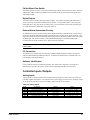
12. Perform a preliminary leak check before insulating the piping and filling the system.
13. Piping insulation should include a vapor barrier to prevent condensation and possible damage to
the building structure.
Figure 5, Typical Field Evaporator Water Piping
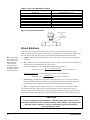
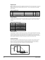
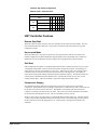
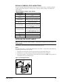
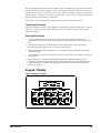
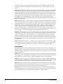
Flow Switch
Mount a water flow switch in either the leaving water line to shut down the unit when water flow is
interrupted. A flow switch is a safety control and should never be used to cycle a unit. The unit
control circuit is provided with a remote start/stop feature.
A flow switch is available from McQuay (part number 017503300). It is a “paddle” type switch and
adaptable to any pipe size from 3” (76mm) to 8” (203mm) nominal. Certain minimum flow rates are
required to close the switch and are listed in Table 5. Installation should be as shown in Figure 6.
Connect the normally open contacts of the flow switch in the unit control center at terminals 5 and 6.
There is also a set of normally closed contacts on the switch that can be used for an indicator light or
an alarm to indicate when a “no flow” condition exists. Freeze protect any flow switch that is installed
outdoors. Differential pressure switches are not recommended for outdoor installation.
IOMM ACR/AGR-1
9
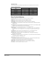
Table 5, Flow Switch Minimum Flow Rates
NOMINAL PIPE SIZE
INCHES (mm)
MINIMUM REQUIRED FLOW TO
ACTIVATE SWITCH - gpm (L/s)
1 (25.4)
1 1/4 (31.8)
1 1/2 (38.1)
2 (50.8)
2 1/2 (63.50
3 (76.20
4 (101.6)
5 (127.0)
6 (152.4)
6.00 (0.38)
9.80 (0.62)
12.70 (0.80)
18.80 (1.20)
24.30 (1.50)
30.00 (1.90)
39.70 (2.50)
58.70 (3.70)
79.20 (5.00)
Figure 6, Flow Switch Installation
Flow direction marked
on switch
1" (25mm) NPT flow
switch connection
Tee
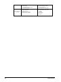
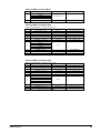
Glycol Solutions
The use of a glycol/water mixture in the CDE evaporator to prevent freezing will reduce system
capacity and efficiency and increase pressure drop. The system capacity, required glycol solution flow
rate, and pressure drop with glycol may be calculated using the following formulas and tables.
Note: The procedure
does not specify the
type of glycol. Use
the derate factors
found Table 6 for
corrections when
using ethylene glycol
and those in Table 7
for propylene glycol.
1.
Capacity – Multiply the capacity based on water by the Capacity correction factor from Table 6
or Table 7.
2.
Flow – Multiply the water evaporator flow by the Flow correction factor from Table 6 or Table 7 to
determine the increased evaporator flow due to glycol
If the flow is unknown, it can be calculated from the following equation:
24 × Tons Capacity( glycol)
Glycol Flow (gpm) =
× Flow Correction Factor
Delta − T
For Metric Applications – Use the following equation for metric applications:
kW Capacity
Glycol Flow (l/s) =
× Flow Correction Factor
4 .18 × Delta − T
3.
Pressure drop -- Multiply the water pressure drop from Figure 7 by Pressure Drop correction
factor from Table 6 or Table 7 to obtain corrected glycol pressure drop. High concentrations of
propylene glycol at low temperatures may cause unacceptably high pressure drops.
4.
Power -- Multiply the water system power by Power correction factor from Table 6 or Table 7.
Test coolant with a clean, accurate glycol solution hydrometer (similar to that found in service
stations) to determine the freezing point. Obtain percent glycol from the freezing point table below. It
is recommended that a minimum of 25% solution by weight be used for protection against corrosion.
CAUTION
Do not use automotive grade antifreeze. Industrial grade glycols must be used.
Automotive antifreeze contains inhibitors that will cause plating on the copper tubes
within the chiller evaporator. The type and handling of glycol used must be
consistent with local codes.
10
IOMM ACR/AGR-1
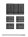
Table 6, Ethylene Glycol Factors
%
E.G.
10
20
30
40
50
Freeze Point
°F
°C
26
-3
18
-8
7
-14
-7
-22
-28
-33
Capacity
Power
Flow
Pressure Drop
0.991
0.982
0.972
0.961
0.946
0.996
0.992
0.986
0.976
0.966
1.013
1.040
1.074
1.121
1.178
1.070
1.129
1.181
1.263
1.308
Capacity
Power
Flow
Pressure Drop
0.987
0.975
0.962
0.946
0.929
0.992
0.985
0.978
0.971
0.965
1.010
1.028
1.050
1.078
1.116
1.068
1.147
1.248
1.366
1.481
Table 7, Propylene Glycol Factors
%
P.G.
10
20
30
40
50
Freeze Point
°F
°C
26
-3
19
-7
9
-13
-5
-21
-27
-33
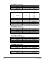
Table 8, Capacity and Power Derates
ALTITUDE
SEA
LEVEL
2000 feet
(610 m)
4000 feet
(1220 m)
6000 feet
(1830 m)
Chilled Water
Delta-T
Fouling Factor
0.0001 (0.0176)
0.00025 (0.044)
0.00075 (0.132)
0.00175 (0.308)
°F
°C
Cap.
Power
Cap.
Power
Cap.
Power
Cap.
Power
6
3.3
0.992
0.995
0.985
0.993
0.962
0.986
0.919
0.972
8
4.4
0.995
0.997
0.988
0.995
0.965
0.988
0.922
0.974
10
5.6
1.000
1.000
0.993
0.998
0.970
0.991
0.927
0.977
12
6.7
1.005
1.002
0.998
1.000
0.975
0.993
0.932
0.979
14
6.8
1.010
1.005
1.003
1.003
0.980
0.996
0.936
0.982
16
8.9
1.014
1.007
1.007
1.005
0.984
0.998
0.940
0.984
6
3.3
0.978
1.005
0.971
1.003
0.949
0.996
0.906
0.982
8
4.4
0.982
1.007
0.975
1.005
0.953
0.998
0.910
0.984
10
5.6
0.986
1.009
0.979
1.007
0.956
1.000
0.914
0.986
12
6.7
0.992
1.011
0.985
1.009
0.962
1.002
0.919
0.988
14
6.8
0.997
1.014
0.990
1.012
0.967
1.005
0.924
0.991
16
8.9
1.000
1.016
0.993
1.014
0.970
1.007
0.927
0.993
6
3.3
0.966
1.016
0.959
1.014
0.937
1.007
0.895
0.993
8
4.4
0.969
1.018
0.962
1.016
0.940
1.009
0.898
0.995
10
5.6
0.973
1.021
0.966
1.019
0.944
1.012
0.902
0.998
12
6.7
0.978
1.025
0.971
1.023
0.949
1.016
0.906
1.002
14
6.8
0.982
1.027
0.975
1.025
0.953
1.018
0.910
1.004
16
8.9
0.986
1.028
0.979
1.026
0.956
1.019
0.914
1.005
6
3.3
0.953
1.025
0.946
1.023
0.924
1.016
0.883
1.002
8
4.4
0.955
1.028
0.948
1.026
0.926
1.019
0.885
1.005
10
5.6
0.959
1.031
0.952
1.029
0.930
1.022
0.889
1.008
12
6.7
0.963
1.034
0.956
1.032
0.934
1.024
0.893
1.011
14
6.8
0.968
1.036
0.961
1.034
0.939
1.026
0.897
1.013
16
8.9
0.972
1.037
0.965
1.035
0.943
1.027
0.901
1.014
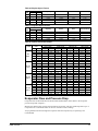
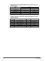
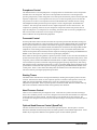
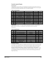
Evaporator Flow and Pressure Drop
Evaporator flow rate must fall between the minimum and maximum values shown in the evaporator
pressure drop table on Figure 7.
Measure the chilled water pressure drop through the evaporator at factory installed pressure taps. It
is important not to include the effect of valves or strainers in these readings.
Varying chilled water flow through the evaporator while the compressor(s) are operating is not
recommended.
IOMM ACR/AGR-1
11
Figure 7, Pressure Drop Curve
CDE
Size
AGR
Unit
Size
1204-1
1255-1
1455-1
-
070 AM
075 AM
080 AM
085 AM
090 AM
095 AM
100 AM
PD
ft of Water
11.2
8.9
10.3
11.8
10.5
12.0
13.4
NOMINAL
Flow
gpm
lps
162
10.22
172
10.85
187
11.80
202
12.74
208
13.12
224
14.13
238
15.02
PD
ft of Water
28.1
22.5
25.9
29.7
26.3
30.0
33.6
MAXIMUM
Flow
gpm
270
287
312
337
347
373
397
lps
17.03
18.09
19.66
21.24
21.87
23.55
25.02
PD
ft of Water
4.8
3.8
4.4
5.0
4.5
5.2
5.7
MINIMUM
Flow
gpm
101
108
117
126
130
140
149
lps
6.39
6.78
7.37
7.97
8.20
8.83
9.38
Minimum and maximum flows are to ensure the Delta-T for each unit size falls within the 6 - 16°F range for proper unit control.
12
IOMM ACR/AGR-1
Refrigerant Piping
Introduction
Proper refrigerant piping can represent the difference between a reliable, trouble free system and
months or years of inefficient, problematic performance.
System concerns related to piping are:
1.
Refrigerant pressure drop
2.
Solid liquid feed to the expansion valve(s)
3.
Continuous oil return
The most important and least understood is number 3. “Continuous oil return”. The failure of oil to
return at or close to the rate of displacement from the compressor can result in oil trapping and
ultimate compressor failure.
On the other hand, the instantaneous return of a large volume of compressor oil, as a slug, can be
equally damaging to a compressor.
All compressors displace some oil during operation. Reciprocating compressors displace more than
centrifugals, scroll and McQuay screw compressors since oil is carried into compressor cylinders with
suction gas; and oil present on cylinder walls is entrained by that same gas as it is being compressed.
The sum of the two is then pumped into the discharge piping.
Also more oil is displaced at start-up of a compressor than occurs during a normal running period.
Thus, if a compressor experiences excessive starts because of recycling pumpdown control, the larger
quantity of oil pumped out is trapped in the condenser with the refrigerant charge, and may not return
regardless of the adequacy of the piping system.
A similar problem to a lesser extent occurs when the equipment is oversized for the available cooling
load.
In short, extreme care should be exercised to assure that both piping and controls are suitable for the
application such that displaced oil is returned to the compressor moderately. Note, too, that oil loss to
the system can be due to a hang up in the evaporator, as well as in the piping.
Suction Lines
McQuay recommends the use of ASHRAE for guidelines in sizing and routing piping with one
exception. See the 1998 ASHRAE Handbook Refrigeration Edition, Chapter 2, for tables and
guidelines. The single exception is to the piping of direct expansion cooling coils located above the
compressors. In all cases, regardless of whether the equipment has pumpdown control or not, a trap
in the suction line equal to the height of the coil section is recommended. In its absence, upon a
power failure, all of the liquid in the coil will fall by gravity to the compressor below.
Suction line gas velocities may range between 900 and 4000 feet per minute. Consideration should be
given to the possibility of objectionable noise in or adjacent to occupied space. Where this is a
concern, gas velocities on the low side are recommended.
Routing must also take into account the requirement established in the latest ANSI/ASHRAE 15.
To size the suction line, determine:
a. The maximum tons for the circuit
b. The actual length in feet
c. The equivalent length contributed by elbows, fittings, valves or other refrigerant specialties.
ASHRAE Tables 2-10, 11 & 12
d. If a vertical riser exists including the trap at the coil, determine the minimum tons for the circuit.
IOMM ACR/AGR-1
13
Add b and c above to obtain the total equivalent feet. Use ASHRAE Table 3 (for R22) or Table 4 (for
R134a). Suction line selections are based upon the pressure equivalent of a 2ºF loss per 100
equivalent feet.
Select a line size that displays an equal or slightly larger tons then that determined in 1a) above.
To determine the actual line loss:
1.
Modify the table tons by the value in Note 4 of Table 3 or 4 for the design condensing
temperature.
2.
Use the formula in Note 3 to calculate the line loss in terms of the saturation temperature.
3.
Convert the saturation temperature loss calculated to a pressure drop equivalent using the (Delta)
listed in the table for the comparable delta temperature.
Caution: Excessive pressure drop is undesirable because
•
It reduces available compressor capacity.
•
It increases power consumed from the net tons realized.
•
It may affect the performance of the evaporator and expansion valve previously selected.
The line loss calculated, expressed in temperature, or PSID pressure drop will be used to establish the
temperature required at the evaporator to produce the required cooling, as well as, the suction
pressure that the compressor must operate at to deliver the required capacity.
Having selected the suction line size, based upon total equivalent length and maximum tons, verify the
line size selected will maintain entrainment of the lubricating oil up any vertical risers at the minimum
tons for the circuit. See d above, and ASHRAE Table 2-13.
If the line size selected will not maintain satisfactory oil return in a suction riser, the following options
are available:
The vertical length can be sized smaller to accommodate the lower circuit tons at reduced load.
Minimum compressor capacity can be increased by eliminating the lowest step of compressor
capacity.
Hot gas bypass can be introduced at the distributor to the evaporator, increasing the volume of gas
available in the suction line to entrain the oil.
An oil separator may be installed in the discharge line.
With reciprocating compressor units only, and only as a last resort, double suction risers can be
utilized. A double suction riser works by providing an oil trap to assure the return of some oil, with
refrigerant, up the smaller diameter line. The trap must be as small as possible, there must not be
multiple traps, and whenever double risers are used in a suction line, a suction accumulator with a
controlled oil return must be installed in the line ahead of the compressor.
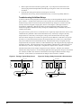
Sizing A Double Riser
At maximum circuit tons, the line size should be selected from the table based upon the recommended
maximum line loss.
With the minimum tons known, a smaller line size should be selected from ASHRAE Chapter 2, Table
13 or 14 capable of entraining oil at the reduced tons. The smaller sized line should be the one
installed to be always active.
The net internal area of this smaller sized line (see Table 13 or 14) should be deducted from the area of
the size selected in paragraph 1) immediately above. The remainder represents the area of the other
riser. From Table 13 or 14, select a line size with an area equal, or close, to the calculated net area. The
combination of these two risers will provide the required performance at full circuit tons. The line
selected for the minimum load should always be active; and both lines should enter the overhead
horizontal line in a manner to prevent spillage of oil back down the other riser.
14
IOMM ACR/AGR-1
Underground Refrigerant Lines
McQuay does not recommend the installation of suction lines underground. If job conditions require
that they be located below ground, a suitable sized suction accumulator must be installed ahead of the
compressor to interrupt liquid refrigerant slugs at start-up.
Long Vertical Riser Installation
Where job conditions require refrigerant gas lifts of more than 25 feet, McQuay recommends the
installation of a short trap half-way up the riser or at not more than 20 feet intervals. These traps are
required to capture and hold small quantities of oil during off cycles.
Liquid Lines
Liquid lines are generally sized for 1 to 2 degree F line losses or their equivalent in pressure drop.
Actual selection can vary based upon the pressure drop expected from refrigerant specialties such as
solenoids, refrigerant driers, valves, etc. piping lifts or risers and the amount of condenser sub-cooling
expected.
The principal concern in sizing and routing liquid lines is assurance that liquid is present in the line at
start-up of the compressor, and that liquid and not vapor is available at the inlet to the expansion
valve during system operation.
Liquid may not be available in a liquid line at start-up if:
1.
The solenoid valve is located adjacent to the condenser or condensing unit; remote from the
expansion valve.
2.
An excessive length of liquid line is located in a heated ambient and the application permits
migration of the refrigerant to a cold air-cooled condenser.
3.
Liquid refrigerant is permitted to gravitate from the liquid line to the condenser because of the
relative location of components.
4.
Liquid line solenoid valves should be located adjacent to the expansion valve with possibly only
a sight glass interposing the two.
In the event 2 or 3 above are possible, the application should include a check valve at the condenser
end of the liquid line. The check valve should be a low pressure drop valve. The line between the
check valve and the solenoid valve can be comparable to a pressure vessel. As the line becomes
heated the pressure will increase so the check valve should include a pressure relief device to relieve
pressure to the condenser side of the circuit. The relief can be sized for a pressure differential from 80
to 180 psi, but not more than 180 psi, and should be auto-resetting as the pressure is relieved.
CAUTION
The liquid line should not include a check valve unless the line also includes an
automatic resetting pressure relief device.
CAUTION
If the relief device being used is relieving from the line to the condenser side of the
check valve, the maximum desirable pressure differential with R-22 refrigerant
is 180 psi, with 134a, 100 psi.
If liquid lines are short, they may be of smaller diameter than the size indicated in the ASHRAE
Refrigerant Handbook, 1998 Edition, Chapter 2, Tables 3 or 4. As indicated above, the designer must
size the liquid line to assure that pure liquid will reach the inlet of the expansion valve. If the
condenser is sized to produce ten degrees F of subcooling. Each degree represents 3.05 psi with R-22
(or 2.2. psi with R-134a). The liquid line and its refrigerant specialties may have pressure losses
IOMM ACR/AGR-1
15
totaling 10 x 3.05 psi (or 10 x 2.2) and still satisfy the objective of delivering solid liquid to the
expansion valve.
In calculating the pressure losses, or gains, note that each foot of rise in a liquid line results in
approximately 0.5 psi loss. Thus a 10 foot rise represent 5 pounds per square inch loss in refrigerant
pressure, or the equivalent of 1.6ºF subcooling with R-22. Total line losses will include values for line
friction, equivalents for valves and elbows and pressure losses from manufacturers’ catalogs for
driers, solenoids, sight glasses, etc.
In estimating condenser subcooling, note that saturated condensing pressure should be read, or
estimated, at the same point in the system where the liquid refrigerant temperature is obtained. That
condensing pressure is not the discharge pressure read at the compressor outlet. Because it is less,
the net value of subcooling will be lower than might otherwise be assumed.
Where rises in liquid lines result in a 0.5 psi loss per foot of lift, a drop in the liquid line results in a rise
in the refrigerant pressure. A substantial drop in the liquid line can assure the existence of pure liquid
at the valve. If it is a substantial increase because of a large drop, the expansion valve selection must
be re-checked to confirm that the valve to be used is not radically oversized.
Liquid Lines from Condensers to Receivers
Receivers in a refrigerant system have both liquid and gas contained within the same vessel. In aircooled condenser applications, the condensing temperature can change rapidly resulting in the
requirement for more liquid at a lower temperature and pressure to be introduced into the receiver.
In order for this flow of lower temperature and pressure of liquid refrigerant to enter the receiver, 1) the
receiver must be located below the condenser outlet with no restrictions in the line, and 2) the liquid
line connecting the condenser and the receiver must be sized for a maximum velocity of 100 fpm.
Piping sizes for this are shown in the ASHRAE tables.
Note: If the interconnecting piping described above contains a Seasontrol type head pressure
control valve representing a restriction in the liquid line, a separate vent from the top of the
receiver to the discharge line entering the condenser is required.
Liquid Line Components
To assist in laying out and specifying split systems, the following recommended (or equal)
components can be used.
Table 9, Liquid Line Components
System
Nom.R-22
Tons
(mbh)
Sporlan Part Number Shown - (Equivalents Are Acceptable)
Filter
Solenoid
Sight
Expansion
Unit Conn.
Drier
Valve
Glass
Valve
In/Out
ACR 070A
Circuit #1
Circuit #2
31.6 (379)
36.3 (436)
C-967
C-967
E25S270
E25S270
SA-17S
SA-17S
OVE-30
OVE-40
7/8-1-3/8
7/8-1-3/8
ACR 075A
Circuit #1 & #2
36.3 (436) ea.
C-969
E25S290
SA-19S
OVE-40
1 1/8-1-3/8
ACR 080
Circuit #1 & #2
40.0 (480) ea.
C-969
E25S290
SA-19S
OVE-40
1 1/8-1-3/8
ACR 090A
Circuit #1
Circuit #2
40.8 (490)
49.1 (589)
C-969
C-1449
E25S290
E25S290
SA-19S
SA-19S
OVE-40
OVE-55
1 1/8-1-3/8
1 1/8-1-3/8
ACR 100A
Circuit #1 & #2
49.1 (589) ea.
C-1449
E25S290
SA-19S
OVE-55
1 1/8-1-3/8
ACR 110A
Circuit #1
Circuit #2
49.1 (589)
57.4 (689)
C-1449
C-1449
E25S290
E25S290
SA-19S
SA-19S
OVE-55
OVE-70
1 1/8-1-3/8
1 1/8-1-3/8
ACR 120A
Circuit #1
57.4 (689) ea.
C-1449
E25S290
SA-19S
OVE-70
1 1/8-1-3/8
Unit
Model
16
IOMM ACR/AGR-1
Physical Data
AGR-AM
Table 10, AGR 070AM - 085AM
PHYSICAL DATA
STANDARD EFFICIENCY
BASIC DATA
Unit Capacity @ ARI Conditions (1), Tons (kW)
Number Of Refrigerant Circuits
Unit Operating Charge, R-22, lbs. (kg)
Unit Operating Charge, R-134a, , lbs. (kg)
Cabinet Dimensions, LxWxH, In.
Cabinet Dimensions, LxWxH, (mm)
Unit Operating Weight, Lbs. (kg)
Unit Shipping Weight, Lbs. (kg)
Add'l Weight If Copper Finned Coils, Lbs. (kg)
COMPRESSORS
Type
Nominal Horsepower
Number Of Cylinders Per Compressor
Oil Charge Per Compressor, oz.
Oil Charge Per Compressor, (g)
070AM
Ckt.1
Ckt.2
67.5 (237.6)
2
60 (27.2) 84 (38.1)
63 (28.6) 88 (40.0)
94.0 x 88.2 x 96.2
2388 x 2241 x 2444
4276
(5506)
4169
(5359)
830
(375)
Semi-Hermetic
35
40
6
6
140
255
(3969)
(7229)
AGR MODEL NUMBER
075AM
080AM
Ckt.1
Ckt.2
Ckt.1
Ckt.2
70.1 (246.7)
77.9 (273.9)
2
2
84 (38.1) 86 (39.9) 86 (39.9) 86 (39.9)
88 (40.0) 90 (41.9) 90 (41.9) 90 (41.9)
136.4 x 88.2 x 96.2
136.4 x 88.2 x 96.2
3463 x 2241 x 2444
3463 x 2241 x 2444
5506
(2497)
5740
(2604)
5359
(2431)
5593
(2537)
1245
(565)
1245
(565)
Semi-Hermetic
40
40
6
6
255
255
(7229)
(7229)
CAPACITY REDUCTION STEPS - PERCENT OF COMPRESSOR DISPLACEMENT
Standard Staging - Circuit #1 in Lead
0-16-33-49-67
0-17-33-50-67
-83-100
-83-100
Standard Staging - Circuit #2 in Lead
0-17-33-51-67
0-17-33-50-67
-84-100
-83-100
Semi-Hermetic
40
50
6
8
255
255
(7229)
(7229)
0-15-42-58-73
-86-100
0-27-42-56-71
-85-100
085AM
Ckt.1
Ckt.2
84.7 (298.1)
2
86 (39.9) 86 (39.9)
90 (41.9) 90 (41.9)
136.4 x 88.2 x 96.2
3463 x 2241 x 2444
5921
(2686)
5774
(2619)
1245
(565)
Semi-Hermetic
50
50
8
8
255
255
(7229)
(7229)
0-25-50-63-75
-88-100
0-25-50-63-75
-88-100
CONDENSERS - HIGH EFFICIENCY FIN AND TUBE TYPE WITH INTEGRAL SUBCOOLING
Coil Face Area, sq. ft.
58
58
87
87
87
87
87
87
Coil Face Area, (m2)
(5.4)
(5.4)
(8.1)
(8.1)
(8.1)
(8.1)
(8.1)
(8.1)
Finned Height x Finned Length, In.
100x 83.5 100x 83.5 100x125.3 100x125.3 100x125.3 100x125.3 100x125.3 100x125.3
2032 x
2032 x
2540 x
2540 x
2540 x
2540 x
2540 x
2540 x
Finned Height x Finned Length, (mm)
2121
2121
3183
3183
3183
3183
3183
3183
Fins Per Inch x Rows Deep
16 x 3
16 x 3
16 x 3
16 x 3
16 x 3
16 x 3
16 x 3
16 x 3
Pumpdown capacity @ 90% lbs. (kg)
108 (49)
108 (49)
162 (73)
162 (73)
162 (73)
162 (73)
162 (73)
162 (73)
Maximum Relief Valve Pressure Setting, psig (kPa)
450 (3103) 450 (3103) 450 (3103) 450 (3103) 450 (3103) 450 (3103) 450 (3103) 450 (3103)
CONDENSER FANS – DIRECT DRIVE PROPELLER TYPE
Number Of Fans - Fan Diameter, In. (mm)
4 - 28 (712)
Number Of Motors - HP (kW)
4 - 2.0 (1.5)
Fan And Motor RPM, 60Hz
1140
60 Hz Fan Tip Speed, fpm (m/Sec)
8357 (35.4)
60 Hz Total Unit Airflow, cfm (m3/sec)
40800 (19.3)
6 - 28 (712)
6 - 2.0 (1.5)
1140
8357 (35.4)
61200 (28.9)
REMOTE DIRECT EXPANSION EVAPORATOR - BAFFLED SHELL AND THRU-TUBE
Model Number
1204-1
1255-1
Diameter, in. - Length, ft.
12.75- 4
12.75 - 5.5
Diameter, (mm) – Length, (mm)
324 - 1220
324 - 1676
Water Volume, gallons, (l)
12.8 (48.5)
17.6 (66.6)
Maximum Water Pressure, psig (kPa)
175 (1207)
175 (1207)
Maximum Refrigerant Working Pressure, psig (kPa)
225 (1552)
225 (1552)
Water Inlet / Outlet Victaulic Connections, In. (mm)
5 (141.3)
5 (141.3)
Drain - NPT int, In. (mm)
.375 (9.5)
.375 (9.5)
Vent - NPT int, In. (mm)
.375 (9.5)
.375 (9.5)
6 - 28 (712)
6 - 2.0 (1.5)
1140
8357 (35.4)
61200 (28.9)
6 - 28 (712)
6 - 2.0 (1.5)
1140
8357 (35.4)
61200 (28.9)
1255-1
12.75 - 5.5
324 - 1676
17.6 (66.6)
175 (1207)
225 (1552)
5 (141.3)
.375 (9.5)
.375 (9.5)
1255-1
12.75 - 5.5
324 - 1676
17.6 (66.6)
175 (1207)
225 (1552)
5 (141.3)
.375 (9.5)
.375 (9.5)
NOTES:
1.
Includes evaporator. Does not include suction and liquid line charge. Outdoor unit and evaporator are shipped with R-22 holding charge.
2.
Units with 1.0 Hp Fan Motors, Uses 1.5 Hp Fan Motors when unit is 380V / 60 Hz and 575V / 60Hz.
IOMM ACR/AGR-1
17
Table 11, AGR 090AM - 100AM
PHYSICAL DATA
STANDARD EFFICIENCY
BASIC DATA
Unit Capacity @ ARI Conditions (1), Tons (kW)
Number Of Refrigerant Circuits
Unit Operating Charge, R-22, lbs.(kg)
Unit Operating Charge, R-134a, lbs.(kg)
Cabinet Dimensions, LxWxH, In.
Cabinet Dimensions, LxWxH, (mm)
Unit Operating Weight, Lbs. (kg)
Unit Shipping Weight, Lbs. (kg)
Add'l Weight If Copper Finned Coils, Lbs. (kg)
COMPRESSORS
Type
Nominal Horsepower
Number Of Cylinders Per Compressor
Oil Charge Per Compressor, oz.
Oil Charge Per Compressor, (g)
090AM
Ckt.1
Ckt.2
86.7 (305.2)
2
90 (40.8) 90 (40.8)
94 (42.8) 94 (42.8)
136.4 x 88.2 x 96.2
3463 x 2241 x 2444
6184
(2805)
6008
(2725)
1245
(565)
AGR MODEL NUMBER
095AM
Ckt.1
Ckt.2
94.0 (330.1)
2
90 (40.8) 90 (40.8)
94 (42.8) 94 (42.8)
136.4 x 88.2 x 96.2
3463 x 2241 x 2444
6194
(2810)
6018
(2730)
1245
(565)
100AM
Ckt.1
Ckt.2
100.1 (352.0)
2
92 (41.7) 92 (41.7)
94 (42.8) 94 (42.8)
136.4 x 88.2 x 96.2
3463 x 2241 x 2444
6194
(2810)
6018
(2730)
1245
(565)
Semi-Hermetic
50
50
8
8
255
255
(7229)
(7229)
Semi-Hermetic
50
60
8
8
255
255
(7229)
(7229)
Semi-Hermetic
60
60
8
8
255
255
(7229)
(7229)
CAPACITY REDUCTION STEPS - PERCENT OF COMPRESSOR DISPLACEMENT
Standard Staging - Circuit #1 in Lead
0-25-50-63-75
0-23-50-61-75
-88-100
-86-100
Standard Staging - Circuit #2 in Lead
0-25-50-63-75
0-27-50-64-75
-88-100
-89-100
0-25-50-63-75
-88-100
0-25-50-63-75
-88-100
CONDENSERS - HIGH EFFICIENCY FIN AND TUBE TYPE WITH INTEGRAL SUBCOOLING
Coil Face Area, sq. ft.
87
87
87
87
87
87
Coil Face Area, (m2)
(8.1)
(8.1)
(8.1)
(8.1)
(8.1)
(8.1)
Finned Height x Finned Length, In.
100x125.3 100x125.3 100x125.3 100x125.3 100x125.3 100x125.3
Finned Height x Finned Length, (mm)
2540 x
2540 x
2540 x
2540 x
2540 x
2540 x
3183
3183
3183
3183
3183
3183
Fins Per Inch x Rows Deep
16 x 3
16 x 3
16 x 3
16 x 3
16 x 3
16 x 3
Pumpdown capacity @ 90% lbs. (kg)
162 (73)
162 (73)
162 (73)
162 (73)
162 (73)
162 (73)
Maximum Relief Valve Pressure Setting, psig (kPa)
450 (3103) 450 (3103) 450 (3103) 450 (3103) 450 (3103) 450 (3103)
CONDENSER FANS – DIRECT DRIVE PROPELLER TYPE
Number Of Fans - Fan Diameter, in. (mm)
6 - 28 (712)
Number Of Motors - HP (kW)
6 - 2.0 (1.5)
Fan And Motor RPM, 60Hz
1140
60 Hz Fan Tip Speed, fpm (m/sec)
8357 (35.4)
60 Hz Total Unit Airflow, cfm (m3/sec)
61200 (28.9)
DIRECT EXPANSION EVAPORATOR - BAFFLED SHELL AND THRU-TUBE
Model Number
1455-1
Diameter, in. - Length, ft.
14 - 5.5
Diameter, (mm) – Length, (mm)
356 - 1676
Water Volume, gallons, (l)
21.2
(80.3)
Maximum Water Pressure, psig (kPa)
175 (1207)
Maximum Refrigerant Working Pressure, psig (kPa)
225 (1552)
Water Inlet / Outlet Victaulic Connections, In. (mm)
5 (141.3)
Drain - NPT int, In. (mm)
.375 (9.5)
Vent - NPT int, In. (mm)
.375 (9.5)
6 - 28 (712)
6 - 2.0 (1.5)
1140
8357 (35.4)
61200 (28.9)
1455-1
14 - 5.5
356 - 1676
21.2
(80.3)
175 (1207)
225 (1552)
5 (141.3)
.375 (9.5)
.375 (9.5)
6 - 28 (712)
6 - 2.0 (1.5)
1140
8357 (35.4)
61200 (28.9)
1455-1
14 - 5.5
356 - 1676
21.2
(80.3)
175 (1207)
225 (1552)
5 (141.3)
.375 (9.5)
.375 (9.5)
NOTES:
1.
Includes evaporator. Does not include suction and liquid line charge. Outdoor unit and evaporator are shipped with R-22 holding charge.
2.
Units with 1.0 Hp Fan Motors, Uses 1.5 Hp Fan Motors when unit is 380V / 60 Hz and 575V / 60Hz.
18
IOMM ACR/AGR-1
Table 12, ACR 060AS - 070AS
PHYSICAL DATA
STANDARD EFFICIENCY
BASIC DATA
Unit Capacity @ ARI Conditions (1), mbh (kW)
Number Of Refrigerant Circuits
Unit Operating Charge, R-22, Lbs.
Unit Operating Charge, R-22, (kg)
Cabinet Dimensions, LxWxH, In.
Cabinet Dimensions, LxWxH, (mm)
Unit Operating Weight, Lbs. (kg)
Unit Shipping Weight, Lbs. (kg)
Add'l Weight If Copper Finned Coils, Lbs. (kg)
Ckt.1
Ckt.2
703 (205.9)
2
46
46
(20.9)
(20.9)
94.0 x 88.2 x 86.2
2388 x 2241 x 2190
3642
(1652)
3550
(1610)
665 (300)
ACR MODEL NUMBER
065AS
Ckt.1
Ckt.2
738 (216.1)
2
46
46
(20.9)
(20.9)
94.0 x 88.2 x 86.2
2388 x 2241 x 2190
3712
(1684)
3620
(1642)
665 (300)
070AS
Ckt.1
Ckt.2
762 (238.5)
2
55
55
(24.9)
(24.9)
94.0 x 88.2 x 96.2
2388 x 2241 x 2444
3745
(1699)
3635
(1649)
830 (375)
Semi-Hermetic
30
30
4
6
140
140
(3969)
(3969)
Semi-Hermetic
30
30
6
6
140
140
(3969)
(3969)
Semi-Hermetic
30
35
6
6
140
140
(3969)
(3969)
0-17-33-50-67
-83-100
0-17-33-50-67
-83-100
0-15-33-49-67
-82-100
0-18-33-51-67
060AS
COMPRESSORS
Type
Nominal Horsepower
Number Of Cylinders Per Compressor
Oil Charge Per Compressor, Oz.
Oil Charge Per Compressor, (g)
CAPACITY REDUCTION STEPS - PERCENT OF COMPRESSOR DISPLACEMENT
Standard Staging - Circuit #1 in Lead
0-23-41-64-82-100
Standard 6 Stages (2)
Standard Staging m 3- Circuit #2 in Lead
0-18-41-59-82-100
Standard 6 Stages (2)
CONDENSERS - HIGH EFFICIENCY FIN AND TUBE TYPE WITH INTEGRAL SUBCOOLING
Coil Face Area,Sq. ft.
46.4
46.4
46.4
46.4
58
58
Coil Face Area, (m2)
(4.3)
(4.3)
(4.3)
(4.3)
(5.4)
(5.4)
Finned Height x Finned Length, In.
80 x 83.5
80 x 83.5
80 x 83.5
80 x 83.5
100x 83.5
100x 83.5
Finned Height x Finned Length, (mm)
2032 x 2121 2032 x 2121 2032 x 2121 2032 x 2121 2032 x 2121 2032 x 2121
Fins Per Inch x Rows Deep
16 x 3
16 x 3
16 x 3
16 x 3
16 x 3
16 x 3
Pumpdown Capacity @ 90% Full (lbs)
86
86
86
86
108
108
Pumpdown Capacity @ 90% Full (kgs)
(39.)
(39.)
(39.)
(39.)
(49.)
(49.)
Maximum Relief Valve Pressure Setting, psig (kPa)
450 (3103) 450 (3103) 450 (3103) 450 (3103) 450 (3103) 450 (3103)
CONDENSER FANS - DIRECT DRIVE PROPELLER TYPE
Number Of Fans - Fan Diameter, in. (mm)
Number Of Motors - HP (kW)
Fan And Motor RPM, 60Hz
60 Hz Fan Tip Speed, FPM (m/Sec)
60 Hz Total Unit Airflow, CFM (m3/sec)
4 - 28 (712)
4 - 1.5 (1.1)
1140
8357 (35.4)
36800 (17.4)
4 - 28 (712)
4 - 1.5 (1.1)
1140
8357 (35.4)
36800 (17.4)
4 - 28 (712)
4 - 2.0 (1.5)
1140
8357 (35.4)
40800 (19.3)
NOTES:
1.
Does not include evaporator, suction or liquid line charge. Unit shipped with R-22 holding charge.
2.
Units with 1.0 Hp Fan Motors, Uses 1.5 Hp Fan Motors when unit is 380V / 60 Hz and 575V / 60Hz.
IOMM ACR/AGR-1
19
Table 13, ACR 075A - 090A
PHYSICAL DATA
STANDARD EFFICIENCY
BASIC DATA
Unit Capacity @ ARI Conditions (1), mbh (kW)
Number Of Refrigerant Circuits
Unit Operating Charge, R-22, Lbs.
Unit Operating Charge, R-22, (kg)
Cabinet Dimensions, LxWxH, In.
Cabinet Dimensions, LxWxH, (mm)
Unit Operating Weight, Lbs. (kg)
Unit Shipping Weight, Lbs. (kg)
Add'l Weight If Copper Finned Coils, Lbs. (kg)
Ckt.2
871 (255.0)
2
55
55
(24.9)
(24.9)
94.0 x 88.2 x 96.2
2388 x 2241 x 2444
3935
(1785)
3825
(1735)
830 (375)
ACR MODEL NUMBER
080AS
Ckt.1
Ckt.2
959 (280.7)
2
80
80
(36.3)
(36.3)
136.4 x 88.2 x 96.2
3463 x 2241 x 2444
4670
(2118)
4510
(2046)
1245
(565)
090AS
Ckt.1
Ckt.2
1078 (315.8)
2
80
80
(36.3)
(36.3)
136.4 x 88.2 x 96.2
3463 x 2241 x 2444
4905
(2225)
4745
(2152)
1245
(565)
Semi-Hermetic
35
35
6
6
140
140
(3969)
(3969)
Semi-Hermetic
40
40
6
6
255
255
(7229)
(7229)
Semi-Hermetic
40
50
6
8
255
255
(7229)
(7229)
0-17-33-50-67
-83-100
0-17-33-50-67
-83-100
0-15-42-58-73
-86-100
0-27-42-56-71
-85-100
075AS
Ckt.1
COMPRESSORS
Type
Nominal Horsepower
Number Of Cylinders Per Compressor
Oil Charge Per Compressor, Oz.
Oil Charge Per Compressor, (g)
CAPACITY REDUCTION STEPS - PERCENT OF COMPRESSOR DISPLACEMENT
Standard Staging - Circuit #1 in Lead
Standard 6 Stages
Standard Staging - Circuit #2 in Lead
Standard 6 Stages
0-16-33-49-67
-83-100
0-17-33-51-67
-84-100
CONDENSERS - HIGH EFFICIENCY FIN AND TUBE TYPE WITH INTEGRAL SUBCOOLING
Coil Face Area,Sq. Ft.
Coil Face Area, (M2)
Finned Height x Finned Length, In.
Finned Height x Finned Length, (mm)
Fins Per Inch x Rows Deep
Pumpdown Capacity @ 90% Full (lbs)
Pumpdown Capacity @ 90% Full (kgs)
Maximum Relief Valve Pressure Setting, psig (kPa)
CONDENSER FANS - DIRECT DRIVE PROPELLER TYPE
Number Of Fans - Fan Diameter, In. (mm)
Number Of Motors - HP (kW)
Fan And Motor RPM, 60Hz
60 Hz Fan Tip Speed, FPM (M/Sec)
60 Hz Total Unit Airflow, CFM (M3/sec)
58
58
87
87
87
87
(5.4)
(5.4)
(8.1)
(8.1)
(8.1)
(8.1)
100x 83.5
100x 83.5 100x125.9 100x125.9 100x125.9 100x125.9
2032 x 2121 2032 x 2121 2540 x 3183 2540 x 3183 2540 x 3183 2540 x 3183
16 x 3
16 x 3
16 x 3
16 x 3
16 x 3
16 x 3
108
108
162
162
162
162
(49.)
(49.)
(73.5)
(73.5)
(73.5)
(73.5)
450 (3103) 450 (3103) 450 (3103) 450 (3103) 450 (3103) 450 (3103)
4 - 28 (712)
4 - 2.0 (1.5)
1140
8357 (35.4)
40800 (19.3)
6 - 28 (712)
6 - 2.0 (1.5)
1140
8357 (35.4)
61200 (28.9)
6 - 28 (712)
6 - 2.0 (1.5)
1140
8357 (35.4)
61200 (28.9)
NOTES:
1.
Nominal capacity based on 95°F ambient air and 45 psig suction pressure, no refrigerant line loss.
2.
Does not include evaporator, suction or liquid line charge. Unit shipped with R-22 holding charge.
3.
Units with 1.0 Hp Fan Motors, Uses 1.5 Hp Fan Motors when unit is 380V / 60 Hz and 575V / 60Hz.
20
IOMM ACR/AGR-1
Table 14, ACR 100A - 120A
PHYSICAL DATA
STANDARD EFFICIENCY
BASIC DATA
Unit Capacity @ ARI Conditions (1), mbh (kW)
Number Of Refrigerant Circuits
Unit Operating Charge, R-22, Lbs.
Unit Operating Charge, R-22, (kg)
Cabinet Dimensions, LxWxH, In.
Cabinet Dimensions, LxWxH, (mm)
Unit Operating Weight, Lbs. (kg)
Unit Shipping Weight, Lbs. (kg)
Add'l Weight If Copper Finned Coils, Lbs. (kg)
Ckt.1
Ckt.2
1178 (344.9)
2
82
82
(37.2)
(37.2)
136.4 x 88.2 x 96.2
3463 x 2241 x 2444
5224
(2370)
5060
(2295)
1245
(565)
ACR MODEL NUMBER
110AS
Ckt.1
Ckt.2
1278 (374.1)
2
82
82
(37.2)
(37.2)
136.4 x 88.2 x 96.2
3463 x 2241 x 2444
5234
(2374)
5070
(2300)
1245
(565)
120AS
Ckt.1
Ckt.2
1376 (402.9)
2
84
84
(38.1)
(38.1)
136.4 x 88.2 x 96.2
3463 x 2241 x 2444
5056
(2293)
4888
(2217)
1245
(565)
Semi-Hermetic
50
50
8
8
255
255
(7229)
(7229)
Semi-Hermetic
50
60
8
8
255
255
(7229)
(7229)
Semi-Hermetic
60
60
8
8
255
255
(7229)
(7229)
0-23-50-61-75
-86-100
0-27-50-64-75
-89-100
0-25-50-63-75
-88-100
0-25-50-63-75
-88-100
100AS
COMPRESSORS
Type
Nominal Horsepower
Number Of Cylinders Per Compressor
Oil Charge Per Compressor, Oz.
Oil Charge Per Compressor, (g)
CAPACITY REDUCTION STEPS - PERCENT OF COMPRESSOR DISPLACEMENT
Standard Staging - Circuit #1 in Lead
Standard 6 Stages
Standard Staging - Circuit #2 in Lead
Standard 6 Stages
0-25-50-63-75
-88-100
0-25-50-63-75
-88-100
CONDENSERS - HIGH EFFICIENCY FIN AND TUBE TYPE WITH INTEGRAL SUBCOOLING
Coil Face Area,Sq. Ft.
87
87
87
87
87
87
Coil Face Area, (M2)
(8.1)
(8.1)
(8.1)
(8.1)
(8.1)
(8.1)
Finned Height x Finned Length, In.
100x125.9 100x125.9 100x125.9 100x125.9 100x125.9 100x125.9
Finned Height x Finned Length, (mm)
2540 x 3183 2540 x 3183 2540 x 3183 2540 x 3183 2540 x 3183 2540 x 3183
Fins Per Inch x Rows Deep
16 x 3
16 x 3
16 x 3
16 x 3
16 x 3
16 x 3
Pumpdown Capacity @ 90% Full (lbs)
162
162
162
162
162
162
Pumpdown Capacity @ 90% Full (kgs)
(73.5)
(73.5)
(73.5)
(73.5)
(73.5)
(73.5)
Maximum Relief Valve Pressure Setting, psig (kPa)
450 (3103) 450 (3103) 450 (3103) 450 (3103) 450 (3103) 450 (3103)
CONDENSER FANS - DIRECT DRIVE PROPELLER TYPE
Number Of Fans - Fan Diameter, In. (mm)
Number Of Motors - HP (kW)
Fan And Motor RPM, 60Hz
60 Hz Fan Tip Speed, FPM (M/Sec)
60 Hz Total Unit Airflow, CFM (M3/sec)
6 - 28 (712)
6 - 2.0 (1.5)
1140
8357 (35.4)
61200 (28.9)
6 - 28 (712)
6 - 2.0 (1.5)
1140
8357 (35.4)
61200 (28.9)
6 - 28 (712)
6 - 2.0 (1.5)
1140
8357 (35.4)
61200 (28.9)
NOTES:
1.
Nominal capacity based on 95°F ambient air and 45 psig suction pressure, no refrigerant line loss.
2.
Does not include evaporator, suction or liquid line charge. Unit shipped with R-22 holding charge.
3.
Units with 1.0 Hp Fan Motors, Uses 1.5 Hp Fan Motors when unit is 380V / 60 Hz and 575V / 60Hz.
IOMM ACR/AGR-1
21
Electrical Data
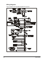
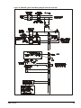
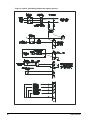
Field Wiring
Power Wiring
CAUTION
Internal power wiring to the compressors for single and multiple point option are
different. Field wiring must be installed according to unit wiring diagram.
Wiring must comply with all applicable codes and ordinances. Warranty is void if wiring is not in
accordance with specifications. Copper wire is required for all power lead terminations at the unit.
Aluminum or copper can be used for all other wiring.
AGR-AM and ACR units have internal power wiring for single point power connection. A single large
power terminal block is provided and wiring within the unit is sized in accordance with the National
Electrical Code. A single field supplied fused disconnect is required. An optional factory mounted
transformer may be installed.
AGR-AM remote water chillers and CDE chillers are equipped with a 420W electric heater to provide
freeze protection if mounted in locations subject to below freezing temperatures. The heater comes
with a receptacle plug that can be used or removed to hard wire to a power supply.
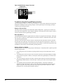
Control Wiring
AGR-AM chillers are equipped with either a Johnson Controls UNT control or a McQuay MicroTech
microprocessor control mounted in the outdoor unit. The control sensor for capacity control must be
mounted in the leaving chilled water line in a thermowell provided in the water chiller nozzle. A sensor
well is also located in the entering nozzle for use with some control options. The sensor is wired to
the control with 30 ft. of cable. If a longer length is required, it is necessary to field splice the cable.
ACR condensing units are not equipped with a capacity control device and one must be field
furnished and installed. Refer to Figure 12. Four or six steps of control are available.
AGR-AM and ACR units connected to water chillers must have a flow switch mounted in the chilled
water line and wired to the control panel per the field wiring diagram. It is recommended that ACR
units connected to DX air coils have an interlock to prevent compressor operation when there is no air
flow.
22
IOMM ACR/AGR-1
AGR-AM Data
ACR Data
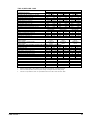
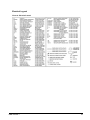
Table 15, 60 Hz, Single Point Power Electrical Data
ACR-AS
Cond.
Unit
Model
POWER SUPPLY
Field Wire
Conduit Hub
Wire
Nominal
Quantity
Quantity
Gauge
Size
3
250
1
2.00
3
250
1
2.00
3
1/0
1
1.5
3
#2
1
1.25
3
#3
1
1.00
Volts
Minimum
Circuit
Ampacity
(MCA)
060As
208
230
380
460
575
231
231
134
114
90
065AS
208
230
380
460
575
237
237
137
117
90
3
3
3
3
3
250
250
1/0
#1
#3
1
1
1
1
1
2.00
2.00
1.50
1.00
1.00
300
300
175
150
125
070AS
208
230
380
460
575
271
258
150
133
98
3
3
3
3
3
300
300
1/0
1/0
#3
1
1
1
1
1
2.50
2.50
1.50
1.50
1.00
350
350
200
175
125
075AS
208
230
380
460
575
298
275
160
146
104
3
3
3
3
3
350
300
2/0
1/0
#2
1
1
1
1
1
2.50
2.50
1.50
1.50
1.25
400
350
225
200
125
070AM
208
230
380
460
575
322
300
190
153
114
3
3
3
3
3
400
350
3/0
2/0
#2
1
1
1
1
1
2.50
2.50
2.00
1.50
1.25
450
400
250
200
150
075AM
208
230
380
460
575
351
329
220
163
126
3
3
3
3
3
500
400
4/0
2/0
#1
1
1
1
1
1
3.00
2.50
2.00
1.50
1.50
450
450
300
225
150
080A
208
230
380
460
575
384
373
240
187
151
6
3
3
3
3
3/0
500
250
3/0
2/0
2
1
1
1
1
2.00
3.00
2.50
2.00
1.50
500
500
300
250
200
085AM
208
230
380
460
575
411
408
256
206
171
6
6
3
3
3
4/0
4/0
300
4/0
3/0
2
2
1
1
1
2.00
2.00
2.50
2.00
2.00
500
500
350
250
225
090AM
208
230
380
460
575
411
408
256
206
171
6
6
3
3
3
4/0
4/0
300
4/0
3/0
2
2
1
1
1
2.00
2.00
2.50
2.00
2.00
500
500
350
250
225
095AM
208
230
380
460
575
461
458
269
220
176
6
6
3
3
3
250
4/0
300
4/0
3/0
2
2
1
1
1
2.00
2.00
2.50
2.00
2.00
600
600
350
300
225
100AM
208
230
380
460
575
501
498
279
231
180
6
6
3
3
3
250
250
300
250
3/0
2
2
1
1
1
2.00
2.00
2.50
2.00
2.00
700
700
350
300
250
080AS
090AS
100AS
110AS
120AS
AGR-AM
Chiller
Unit
Size
Max. Fuse
or
HACR Breaker
Size
300
300
175
150
125
All Electrical Data notes are on page 26
IOMM ACR/AGR-1
23
Table 16, 60 Hz, Compressor & Condenser Fan Motor Amp Draw
ACR-A
Cond.
Unit
Size
AGR-AM
Chiller
Unit
Size
Volts
Rated Load
Amps
Compressors
No.
No.
1
2
Fan
Motors
(Each)
No. Of
Fan
Fan
Motors Motors
(Each)
Locked Rotor Amps
Compressors
Across-The-Line Reduced
No. 1
No. 2
No. 1
470
565
292
470
565
292
285
342
N/A
235
260
141
200
230
130
Inrush
No. 2
340
340
N/A
156
138
060AS
208
230
380
460
575
89
89
52
44
36
95
95
55
47
36
5.8
5.8
3.4
2.8
2.3
4
4
4
4
4
23.7
21.4
14.4
10.7
11.5
065AS
208
230
380
460
575
95
95
55
47
36
95
95
55
47
36
5.8
5.8
3.4
2.8
2.3
4
4
4
4
4
23.7
21.4
14.4
10.7
11.5
565
565
342
260
230
565
565
342
260
230
340
340
N/A
156
138
340
340
N/A
156
138
070AS
208
230
380
460
575
95
95
55
47
36
122
112
65
60
42
5.8
5.8
3.4
2.8
2.3
4
4
4
4
4
23.7
21.4
14.4
10.7
11.5
565
565
342
260
230
650
594
365
315
245
340
340
N/A
156
138
400
340
N/A
195
152
075AS
208
230
380
460
575
122
112
65
60
42
122
112
65
60
42
5.8
5.8
3.4
2.8
2.3
4
4
4
4
4
23.7
21.4
14.4
10.7
11.5
650
594
365
315
245
650
594
365
315
245
400
340
N/A
195
152
400
340
N/A
195
152
070AM
208
230
380
460
575
122
112
65
60
42
135
127
87
63
48
7.8
7.2
4.1
3.6
3.0
4
4
4
4
4
30.5
27.6
20.0
13.8
11.0
650
594
365
315
245
754
594
365
315
245
400
340
N/A
195
152
463
340
N/A
195
152
075AM
208
230
380
460
575
135
127
87
63
48
135
127
87
63
48
7.8
7.2
4.1
3.6
3.0
6
6
6
6
6
30.5
27.6
20.0
13.8
11.0
754
594
365
315
245
754
594
365
315
245
463
340
N/A
195
152
463
340
N/A
195
152
080AM
208
230
380
460
575
135
127
87
63
48
162
162
103
82
68
7.8
7.2
4.1
3.6
3.0
6
6
6
6
6
30.5
27.6
20.0
13.8
11.0
754
594
365
315
245
1070
1070
740
510
405
463
340
N/A
195
152
654
654
N/A
330
262
085AM
208
230
380
460
575
162
162
103
82
68
162
162
103
82
68
7.8
7.2
4.1
3.6
3.0
6
6
6
6
6
30.5
27.6
20.0
13.8
11.0
1070
1070
740
510
405
1070
1070
740
510
405
654
654
N/A
330
262
654
654
N/A
330
262
090AM
208
230
380
460
575
162
162
103
82
68
162
162
103
82
68
7.8
7.2
4.1
3.6
3.0
6
6
6
6
6
30.5
27.6
20.0
13.8
11.0
1070
1070
740
510
405
1070
1070
740
510
405
654
654
N/A
330
262
654
654
N/A
330
262
095AM
208
230
380
460
575
162
162
103
82
68
202
202
113
93
72
7.8
7.2
4.1
3.6
3.0
6
6
6
6
6
30.5
27.6
20.0
13.8
11.0
1070
1070
740
510
405
1070
1070
740
510
405
654
654
N/A
330
262
654
654
N/A
330
262
100AM
208
230
380
460
575
202
202
113
93
72
202
202
113
93
72
7.8
7.2
4.1
3.6
3.0
6
6
6
6
6
30.5
27.6
20.0
13.8
11.0
1070
1070
740
510
405
1070
1070
740
510
405
654
654
N/A
330
262
654
654
N/A
330
262
080AS
090AS
100AS
110AS
120AS
All Electrical Data notes are on page 26
24
IOMM ACR/AGR-1
Table 17, 60 Hz Single Point Power, Field Wiring Data
ACR-AS
Cond.
Unit
Size
AGR-AM
Chiller
Unit
Size
Volts
Wiring to Standard
Power Block
Terminal
Connector Wire Range
Amps
(Copper Wire Only)
Wiring to Optional
Non-Fused Disconnect Switch
Terminal
Connector Wire Range
Amps
(Copper Wire Only)
060AS
208
230
380
460
575
335
335
335
335
335
#
#
#
#
#
4
4
4
4
4
-
400
400
400
400
400
MCM
MCM
MCM
MCM
MCM
250
250
150
150
100
250-500 MCM
250-500 MCM
#2 - 3/0
#2 - 3/0
#6 - 1/0
065AS
208
230
380
460
575
335
335
335
335
335
#
#
#
#
#
4
4
4
4
4
-
400
400
400
400
400
MCM
MCM
MCM
MCM
MCM
250
250
150
150
100
250-500 MCM
250-500 MCM
#2 - 3/0
#2 - 3/0
#6 - 1/0
070As
208
230
380
460
575
335
335
335
335
335
#
#
#
#
#
4
4
4
4
4
-
400
400
400
400
400
MCM
MCM
MCM
MCM
MCM
400
400
250
150
150
250 - 500 MCM
250 - 500 MCM
#4 - 350 MCM
#2 - 3/0
#2 - 3/0
075AS
208
230
380
460
575
335
335
335
335
335
#
#
#
#
#
4
4
4
4
4
-
400
400
400
400
400
MCM
MCM
MCM
MCM
MCM
400
400
250
250
150
250 - 500 MCM
250 - 500 MCM
#4 - 350 MCM
#4 - 350 MCM
#2 - 3/0
070AM
208
230
380
460
575
335
335
335
335
335
#
#
#
#
#
4
4
4
4
4
-
400
400
400
400
400
MCM
MCM
MCM
MCM
MCM
400
400
250
250
150
250 - 500 MCM
250 - 500 MCM
#4 - 350 MCM
#4 - 350 MCM
#2 - 3/0
075AM
208
230
380
460
575
335
335
335
335
335
#
#
#
#
#
4
4
4
4
4
-
400
400
400
400
400
MCM
MCM
MCM
MCM
MCM
400
400
250
250
150
250 - 500 MCM
250 - 500 MCM
#4 - 350 MCM
#4 - 350 MCM
#2 - 3/0
080AM
208
230
380
460
575
840
840
335
335
335
(2 qty.) 1/0 - 600 MCM
(2 qty.) 1/0 - 600 MCM
# 4 - 400 MCM
# 4 - 400 MCM
# 4 - 400 MCM
400
400
250
250
250
250 - 500 MCM
250 - 500 MCM
#4 - 350 MCM
#4 - 350 MCM
#4 - 350 MCM
085AM
208
230
380
460
575
840
840
335
335
335
(2 qty.) 1/0 - 600 MCM
(2 qty.) 1/0 - 600 MCM
# 4 - 400 MCM
# 4 - 400 MCM
# 4 - 400 MCM
N/A
N/A
400
250
250
N/A
N/A
250 - 500 MCM
#4 - 350 MCM
#4 - 350 MCM
090AM
208
230
380
460
575
840
840
335
335
335
(2 qty.) 1/0 - 600 MCM
(2 qty.) 1/0 - 600 MCM
# 4 - 400 MCM
# 4 - 400 MCM
# 4 - 400 MCM
N/A
N/A
400
250
250
N/A
N/A
250 - 500 MCM
#4 - 350 MCM
#4 - 350 MCM
095AM
208
230
380
460
575
840
840
335
335
335
(2 qty.) 1/0 - 600 MCM
(2 qty.) 1/0 - 600 MCM
# 4 - 400 MCM
# 4 - 400 MCM
# 4 - 400 MCM
N/A
N/A
400
250
250
N/A
N/A
250 - 500 MCM
#4 - 350 MCM
#4 - 350 MCM
100AM
208
230
380
460
575
840
840
335
335
335
(2 qty.) 1/0 - 600 MCM
(2 qty.) 1/0 - 600 MCM
# 4 - 400 MCM
# 4 - 400 MCM
# 4 - 400 MCM
N/A
N/A
400
250
250
N/A
N/A
250 - 500 MCM
#4 - 350 MCM
#4 - 350 MCM
080AS
090AS
100AS
110AS
120AS
All Electrical Data notes are on page 26
IOMM ACR/AGR-1
25
Electrical Notes
Notes for “Electrical Data Single Point” Power:
1.
Unit wire size ampacity (MCA) is equal to 125% of the largest compressor-motor RLA plus 100%
of RLA of all other loads in the circuit including the control transformer.
2.
If the control transformer option is furnished, no separate 115V power is required.
3.
If a separate 115V power supply is used for the control circuit, then the wire sizing amps is 10
amps for all unit sizes.
4.
Recommended power lead wire sizes for 3 conductors per conduit are based on 100% conductor
ampacity in accordance with NEC. Voltage drop has not been included. Therefore, it is
recommended that power leads be kept short. All terminal block connections must be made with
copper (type THW) wire.
5.
“Recommended Fuse Sizes” are selected at approximately 150% to 175% of the largest
compressor RLA, plus 100% of all other loads in the circuit.
6.
“Maximum Fuse or HACR breaker size” is selected at approximately 225% of the largest
compressor RLA, plus 100% of all other loads in the circuit.
7.
The recommended power lead wire sizes are based on an ambient temperature of 86°F (30°C).
Ampacity correction factors must be applied for other ambient temperatures. Refer to the
National Electrical Code Handbook.
8.
Must be electrically grounded according to national and local electrical codes.
9.
MCA may vary slightly due to fan motor options such as SpeedTrol, TEFC.
Power Limitations:
Volts within ± 10 percent of nameplate rating. Maximum 3 percent phase unbalance.
Notes for “Compressor and Condenser Fan Amp Draw”:
1.
Compressor RLA values are for wiring sizing purposes only but do not reflect normal operating
current draw at rated capacity. If unit is equipped with SpeedTrol condenser fan motors, the first
motor on each refrigerant circuit is a single phase, 1hp motor, with a FLA of 2.8 amps at 460 volts,
5.6 amps at 208, 230, and 575 volts.
2.
Compressor LRA for reduced inrush start is for the first winding only. If the unit is equipped with
SpeedTrol motors, the first motor is a single phase, 1 hp motor, with a LRA of 7.3 amps at 460
volts, 14.5 amps at 208, 230, and 575 volts.
Notes for “Field Wiring Data”
26
1.
Requires a single disconnect to supply electrical power to the unit. This power supply must
either be fused or use an HACR type circuit breaker.
2.
All field wiring to unit power block or optional non-fused disconnect switch must be copper.
3.
All field wire size values given in table apply to 75°C rated wire per NEC.
IOMM ACR/AGR-1
Electrical Legend
Figure 8, Electrical Legend
IOMM ACR/AGR-1
27
Wiring Diagrams
Figure 9, AGR-AM, Typical Field Wiring with MicroTech Controller
28
IOMM ACR/AGR-1
Figure 10, AGR-AM, Typical Field Wiring Diagram with UNT Controller
IOMM ACR/AGR-1
29
Figure 11, ACR-A, Field Wiring Diagram (No Capacity Control)
30
IOMM ACR/AGR-1
Figure 12, ACR-A, Field Wiring Diagram (Capacity Control Staging)
IOMM ACR/AGR-1
31
Figure 13, AGR-AM, MicroTech Controller Schematic
32
IOMM ACR/AGR-1
Figure 14, AGR-AM, Unit Control Schematic (MicroTech)
IOMM ACR/AGR-1
33
Figure 15, AGR-AM, Staging Schematic (MicroTech)
34
IOMM ACR/AGR-1
Dimensional Data
Figure 16, Dimensions AGR 070AM and ACR 060AS -075AS
ACR
MODEL
NUMBER
060A
065A
070A
075A
-
AGR
MODEL
NUMBER
-
ACR
MODEL
NUMBER
060A
065A
070A
075A
-
AGR
MODEL
NUMBER
-
070AM
070AM
IOMM ACR/AGR-1
OVERALL
HEIGHT
A
86.2 (2190)
86.2 (2190)
86.2 (2190)
96.2 (2444)
96.2 (2444)
COMPRESSOR # 1 (SUCTION #1)
inches (mm)
C
D
E
50.84 (1391) 20.88 (597)
23.52 (597)
50.09 (1272) 20.88 (597)
23.52 (597)
50.09 (1272) 20.88 (597)
23.52 (597)
49.34 (1253) 20.88 (597)
23.52 (597)
49.34 (1253) 20.88 (597)
23.52 (597)
CENTER OF GRAVITY
inches (mm)
X
Y
Z
43.4 (1102)
36.4 (925)
40.7 (1034)
43.4 (1102)
36.4 (925)
40.6 (1031)
43.4 (1102)
36.5 (927)
40.6 (1031)
44.0 (1118)
37.4 (950)
43.2 (1097)
44.0 (1118)
37.5 (953)
43.0 (1092)
COMPRESSOR # 2 (SUCTION #2)
inches (mm)
F
G
H
10.09 (256)
20.88 (597)
23.52 (597)
10.09 (256)
20.88 (597)
23.52 (597)
9.34 (237)
20.88 (597)
23.52 (597)
9.34 (237)
20.88 (597)
23.52 (597)
9.34 (237)
20.88 (597)
25.52 (648)
UNIT WEIGHTS
lb (kg)
OPERATING
SHIPPING
3642 (1652)
3550 (1610)
3712 (1684)
36.20 (1642)
3745 (1699)
3635 (1649)
3935 (1785)
3825 (1735)
4090 (1855)
3980 (1805)
ADDITIONAL WEIGHT FOR
UNITS W/COPPER FIN COILS
lb (kg)
665 (300)
665 (300)
665 (300)
830 (375)
830 (375)
35
Figure 17, AGR 075AM - 100AM and ACR 080AS - 120AS
36
ACR
MODEL
NUMBER
AGR
MODEL
NUMBER
080A
090A
100A
110A
120A
075AM
080AM
085AM
090AM
095AM
100AM
ACR
MODEL
NUMBER
AGR
MODEL
NUMBER
080A
090A
100A
110A
120A
075AM
080AM
085AM
090AM
095AM
100AM
COMPRESSOR # 1 (SUCTION #1)
inches (mm)
C
D
E
88.5 (2248)
20.9 (531)
25.5 (648)
88.5 (2248)
20.9 (531)
25.5 (648)
86.0 (2184)
23.9 (608)
27.8 (707)
86.0 (2184)
23.9 (608)
27.8 (707)
86.0 (2184)
23.9 (608)
27.8 (707)
86.0 (2184)
23.9 (608)
27.8 (707)
59.8
59.8
59.8
59.8
59.8
59.8
CENTER OF GRAVITY
inches (mm)
X
Y
Z
(1519)
37.5 (953)
41.5 (1054)
(1519)
36.9 (937)
40.8 (1036)
(1519)
36.3 (922)
39.9 (1013)
(1519)
37.3 (947)
40.9 (1039)
(1519)
37.3 (947)
39.3 (998)
(1519)
37.3 (947)
39.3 (998)
COMPRESSOR # 2 (SUCTION #2)
inches (mm)
F
G
H
48.5 (1232)
20.9 (531)
25.5 (648)
49.0 (1245)
23.9 (608)
27.8 (707)
49.0 (1245)
23.9 (608)
27.8 (707)
49.0 (1245)
23.9 (608)
27.8 (707)
49.0 (1245)
23.9 (608)
27.8 (707)
49.0 (1245)
23.9 (608)
27.8 (707)
UNIT WEIGHTS
lb (kg)
OPERATING
SHIPPING
4670 (2118)
4510 (2045)
4905 (2224)
4745 (2152)
5089 (2308)
4925 (2234)
5224 (2370)
5060 (2295)
5234 (2374)
5070 (2300)
5238 (2376)
5070 (2300)
ADDITIONAL WEIGHT FOR
COPPER FIN COILS
lb (kg)
1245
1245
1245
1245
1245
1245
(565)
(565)
(565)
(565)
(565)
(565)
IOMM ACR/AGR-1
CDE Evaporator
Figure 18, CDE 1004-1 - 1204-1
CDE
MODEL
NUMBER
CDE-1204-2
CDE-1204-1
CDE-1255-1
CDE-1455-1
C
39.3 (998)
36.0 (914)
54 (1372)
54 (1372)
CDE
MODEL
NUMBER
CDE-1204-2
CDE-1204-1
CDE-1255-1
CDE-1455-1
53.5
53.5
71.5
71.5
CDE
MODEL
NUMBER
CDE-1204-2
CDE-1204-1
CDE-1255-1
CDE-1455-1
WATER CONNECTION
inch (mm)
L
P
9.5 (241)
4.0 (102)
9.5 (241)
5.0 (127)
11.0 (278)
5.0 (127)
11.0 (278)
5.0 (127)
3.0
3.0
3.0
3.0
A
(1359)
(1359)
(1816)
(1816)
K
(76
(76
(76)
(76)
17.5
17.5
17.5
19.1
50.0
50.0
68.0
68.0
R
(1270)
(1270)
(1727)
(1727)
B
(445)
(445)
(445)
(485)
S
52 (1321)
52 (1321)
70.0 (1778)
70.0 (1778)
5.4
7.0
7.0
7.0
T
(137)
(178)
(178)
(178)
DIMENSIONAL DATA
inch (mm)
D
E
7.1 (180)
17.5 (445)
8.8 (224)
17.5 (445)
8.8 (224)
19.0 (483)
8.8 (224)
19.0 (483)
DIMENSIONAL DATA
inch (mm)
U
V
1.8 (45)
2.8 (71)
1.8 (45)
2.8 (71)
1.8 (45)
2.8 (71)
1.8 (45)
2.8 (71)
REFRIGERANT CONNECTION
inch (mm)
M
N
2 1/8 (54)
1 3/8 (35)
2 1/8 (54)
1 3/8 (35)
2 1/8 (54)
1 3/8 (35)
2 1/8 (54)
1 3/8 (35)
12.1
12.1
12.1
12.1
F
(307)
(307)
(307)
(307)
W
16.0 (406
16.0 (406
16.0 (406)
17.6 (447)
2.3
2.3
3.0
3.0
AA
-------------
G
(58)
(58)
(76)
(76)
BB
14.0 (356)
14.0 (356)
14.0 (356)
14.0 (356)
NOTE: CDE physical data can be found in the AGR-AM Physical Data Tables
IOMM ACR/AGR-1
37
Startup
Pre Start-up
The system components must be inspected to ensure that nothing has become loose or damaged
during shipping or installation.
Start-Up
For AGR-AM units refer to the Global UNT Controller or MicroTech Controller sections to become
familiar with the operation before starting chiller.
For ACR units, the field furnished and installed capacity control system should be thoroughly
understood prior to starting the unit.
There should be adequate building load (a minimum of 50 % of unit capacity) to properly check the
operation of the system’s refrigerant circuits.
Record all operating parameters required by the “Compressorized Equipment Warranty Form”. Return
this information within 10 working days to McQuay International as instructed on the form to obtain
full warranty benefits.
1.
Verify chilled water pressure drop across the evaporator or air flow for DX coil.
2.
Verify remote start / stop or time clock has requested the chiller to start.
3.
For UNT control, set the chilled water or leaving air control setpoint to required temperature. (The
system water temperature must be greater than the total of the leaving water temperature setpoint
plus 1/2 the control band before the Global UNT controller will stage on cooling.)
4.
Set the control band to 4°F as a starting point.
5.
Put both circuit switches to the AUTO position.
6.
Put switch S1 to AUTO position.
7.
There will be a delay of 2 minutes after closing S1. The time delay is due to the compressor
inherent motor protection. This may allow more than one compressor to start after this time
period. This should only occur on initial start-up or when power to the chiller has been turned off
and back on. The panel Alarm Light will turn off.
8.
After the system has been operating for a period of time and has become stable, check the
following:
9.
§
Compressor oil level.
§
Refrigerant sight glass for flashing.
§
Rotation of condenser fans.
Complete the “Compressorized Equipment Warranty Form”.
Shutdown
Temporary
1.
Put both circuit switches to Pumpdown and Stop.
2.
After compressors have stopped, put System Switch (S1) to Emergency Stop.
3.
Turn off chilled water pump on water chilling applications. Chilled water pump to operate while
compressors are pumping down.
To start the chiller after a temporary shutdown follow the start up instructions.
38
IOMM ACR/AGR-1
Extended
1.
Front seat both condenser liquid line service valves.
2.
Put both circuit switches in Pumpdown and Stop position.
3.
After the compressors have stopped, put System Switch (S1) in Emergency Stop position.
4.
Front seat both refrigerant circuit discharge valves.
5.
If chilled water system is not drained, maintain power to the evaporator heater to prevent freezing.
Maintain heat tracing on the chilled water lines.
6.
Drain evaporator and water piping to prevent freezing.
7.
If electrical power is on to unit, the compressor crankcase heaters will keep the liquid refrigerant
out of the compressor oil. This will minimize start up time when putting the unit back into service.
The evaporator heater will be able to function.
8.
If electrical power is off, make provisions to power the evaporator heater (if chilled water system
is not drained). Tag all opened electrical disconnect switches to warm against startup before the
refrigerant valves are in the correct operating position. When starting the unit, electrical power
must be on for 24 hours before starting the chiller.
To start the chiller after an extended shutdown, follow the pre startup and startup instructions.
Water Piping Checkout
1.
Check the pump operation and vent all air from the system.
2.
Circulate evaporator water checking for proper system pressure and pressure drop across the
chiller barrel. Compare the pressure drop to the Evaporator water pressure drop curve.
3.
Clean all water strainers before placing the chiller into service.
Refrigerant Piping Checkout
IOMM ACR/AGR-1
1.
Check all exposed brazed joints for evidence of leaks. Joints may have been damaged during
shipping or when the unit was installed.
2.
Check that all refrigerant valves are either opened or closed as required for proper operation of
the chiller.
3.
Check all valve stem packing for leaks. Replace all refrigerant valve caps and tighten.
4.
Check all refrigerant lines to insure that they will not vibrate against each other or against other
chiller components.
5.
Check all flare connections and all refrigerant threaded connectors.
6.
Look for any signs of refrigerant leaks around the condenser coils and for damage during
shipping or installation.
7.
Leak detector is applied externally to refrigerant joints at the factory. Do not confuse this residue
with an oil leak.
8.
Connect refrigerant service gauges to each refrigerant circuit before starting unit.
39
Electrical Check Out
CAUTION
Electrical power must be applied to the compressor crankcase heaters 24 hours
before starting unit.
1.
Open all electrical disconnects and check all power wiring connections. Start at the power block
and check all connections through all components to and including the compressor terminals.
These should be checked again after 3 months of operations and at least yearly thereafter.
2.
Check all control wiring by pulling on the wire at the spade connections and tighten all screw
connections. Check plug-in relays for proper seating and to insure retaining clips are installed.
3.
Put System Switch (S1) to the Emergency Stop position.
4.
Put both circuit #1 & #2 switches to the Pumpdown and Stop position.
5.
Apply power to the unit. The panel Alarm Light will stay on until S1 is closed. Ignore the Alarm
Light for the check out period. If you have the optional Alarm Bell, you may wish to disconnect
it.
6.
Check at the power block or disconnect for the proper voltage and proper voltage between
phases.
7.
Check for 120Vac at the optional control transformer and at TB-2 terminal #1 and the neutral block
(NB).
8.
Check between TB-2 terminal #7 and NB for 120Vac supply for transformer #2.
9.
Check between TB-2 terminal #2 and NB for 120Vac control voltage. This supplies the
compressor crank case heaters.
10. Check between TB-3 terminal #17 and #27 for 24Vac control voltage.
11. Check on the Global UNT controller between terminals marked 24Vac and common for 24Vac
control voltage. Green light on Global UNT controller should be flashing.
40
IOMM ACR/AGR-1
Operation
Hot Gas Bypass (Optional)
This option allows the system to operate at low loads without the ON-OFF cycling of the compressor.
When the hot gas bypass option is used it is required to be on both refrigerant circuits because of the
lead / lag feature of the Global UNT controller.
This option allows passage of discharge gas into the evaporator inlet (between the TX valve and the
evaporator) which generates a false load to supplement the actual chilled water load.
Note: The hot gas bypass valve cannot generate a 100% false load.
The valve that is supplied can provide a load of approximately 10 tons. The system load added to the
ten tons of the hot gas bypass valve has to exceed the compressor capacity for stage 1 compressors
for stable system operation. This requires 3-6 tons of system load.
A solenoid valve in the hot gas bypass lines is wired in parallel with both circuits' liquid line solenoid
valves SV1 and SV2. The hot gas bypass is available whenever a refrigerant circuit is operating. The
hot gas valve is regulating by the evaporator pressure and the remote adjustable bulb. The pressure
regulating valve is factory set to begin opening at 58 psig (32°F for R-22). This setting can be
changed by adjusting the remote adjustable bulb. Remove the cap on the remote bulb and raise the
pressure by turning the adjustment screw clockwise. Lower the pressure by turning the adjusting
screw counterclockwise. This changes the pressure that the hot gas bypass valve will start to open.
Do not force the adjusting screw as this can damage the adjusting assembly.
WARNING
The hot gas line may become hot enough to cause injury.
Be careful during valve checkout.
Note: The remote adjusting bulb must be installed on the outside of the suction line insulation.
The bulb has to have a stable ambient air temperature for proper operation. Placing the bulb in
contact with the evaporator refrigerant line will limit the operation of the hot gas bypass valve.
Filter Driers
Each refrigerant circuit is furnished with a full flow filter drier or an optional replaceable core type
filter-drier. The core assembly of the replaceable core drier consists of a filter core held tightly in the
shell in a manner that allows full flow without bypass.
Pressure drop across the filter drier at full load conditions must not exceed 10 psig. Maximum pressure
drops for other load points can be found in Table 61. Replace the filter drier if the pressure drop
exceeds these values.
CAUTION
Pump out refrigerant before removing end flange for replacement of core(s).
A condenser liquid line service valve is provided for isolating the charge in the condenser, but also
serves as the point from which the liquid line can be pumped out. With the line free of liquid, the filterdrier core(s) can be easily replaced.
IOMM ACR/AGR-1
41
System Adjustment
To maintain peak performance at full load operation, the system superheat and liquid subcooling may
require adjustment. Read the following subsections closely to determine if adjustment is required.
Liquid Sightglass and Moisture Indicator
The color of the moisture indicator is an indication of the dryness of the system and is extremely
important when the system has been serviced. Immediately after the system has been opened for
service, the element may indicate a wet condition. It is recommended that the equipment operate for
about 12 hours to allow the system to reach equilibrium before deciding if the system requires a
change of drier cores.
Bubbles in the sightglass at constant full load conditions indicates a shortage of refrigerant, a
plugged filter-drier, or a restriction in the liquid line. However, it is not unusual to see bubbles in the
sightglass during changing load conditions.
Refrigerant Charging
Liquid line subcooling at the liquid shut-off valve should be between 15° and 20°F at full load. If the
unit is at steady full load operation and bubbles are visible in the sightglass, then check liquid
subcooling.
Thermostatic Expansion Valve
The expansion valve performs one specific function. It keeps the evaporator supplied with the proper
amount of refrigerant to satisfy the load conditions.
The sensing bulb of the expansion valve is installed in the closest straight run of suction line from the
evaporator. The bulb is held on by clamps around the suction line and is insulated to reduce the
effect of surrounding ambient temperatures. In case the bulb must be removed, simply slit the
insulation on each side of the bulb, remove the clamps and then remove the capillary tubing that runs
along the suction line from the valve.
The power element is removable from the valve body without removing the valve from the line.
Note: The superheat is factory set and adjustment is not needed unless operation is outside
the 8° to 12°F range.
CAUTION
Before adjusting superheat, check unit charge is correct and liquid line sightglass is
full with no bubbles.
The suction superheat for the suction leaving the evaporator is set at the factory for 8 to 12 degrees F
at full load. To have full rated unit performance the superheat must be about 8 degrees F at 95°F
outdoor ambient temperature.
Crankcase Heaters
The screw compressors are equipped with internal crankcase heaters. The function of the heater is to
keep the temperature in the crankcase high enough to prevent refrigerant from migrating to the
crankcase and condensing in the oil during off-cycle.
Power must be supplied to the heaters 24 hours before starting the compressors.
42
IOMM ACR/AGR-1
DX Evaporator
The evaporator is of the direct expansion type with removable internally finned tubes. The copper
tubes are individually rolled into heavy duty steel tube sheets and sealed by a steel refrigerant head.
The water connection nozzles that enter and leave the shell are on the same side of the unit. The
water inlet is located on the end having the refrigerant connections. No special attention is required
for the cooler except that clean, filtered water should be supplied.
Sequence of Operation
AGR-AM, Remote Evaporator
Starting
With control power on, 115Vac power is applied through F1 to the compressor crankcase heaters and
control transformer T2. T2 supplies 24Vac to the Global UNT controller. The green light on the Global
UNT controller will begin to flash. The panel Alarm Light will illuminate. Put the System Switch S1
into the AUTO position. This applies power to the control circuit and a digital input to the Global
UNT controller. Control power is applied through the Mechanical High Pressure Control (MHP) to the
compressor inherent motor protectors (MP). After approximately a two (2) minute time delay, the MP’s
are energized and the panel Alarm Light will turn off. If this is a first start, depress the Freezestat Reset
Button for 1 seconds. There is a default time delay of 5 minutes on the Freezestat reset.
Start the chiller water pump and put the chiller into the run mode by closing the remote start / stop
input or time clock input. After the flow switch has made, the Global UNT controller will begin to ramp
up if the chilled water temperature is above the leaving water setpoint dial plus 1/2 the control band
dial. Internal timing functions will vary the stage up time.
The starting refrigerant circuit is switched every ten (10) starts. This maintains equal starts on the first
compressor of each refrigerant circuit. Refrigerant circuit #1 is assumed as the starting circuit for the
following.
When the first stage of cooling is required, relay BO1 will be energized and if the evaporator pressure
is above the LPSS (low pressure starting setpoint), relay BO7 will be energized starting Compressor #1
and energizing the liquid line solenoid valve (SV1) through control relay CCR1.
As additional cooling is required, relay BO2 will be energized and if the evaporator pressure is above
the LPSS (low pressure starting setpoint), relay BO8 will be energized starting Compressor #2 and
energizing the liquid line solenoid valve (SV2) through control relay CCR2.
As additional cooling is required, relays BO3 and BO6 will deenergize compressor unloaders.
The reverse will occur as the cooling requirement is reduced. Relays BO6 and BO3 will open
energizing the compressor unloaders. Relay BO2 will open closing the #2 refrigerant liquid line
solenoid valve. Compressor #2 will continue to operate until the LPLL (low pressure low limit) is
reached or the PDTD (pumpdown delay time period) timer times out. Relay BO8 will open stopping
compressor #2. Relay BO1 will open closing the #1 refrigerant liquid line solenoid valve. Compressor
#1 will continue to operate until the LPLL is reached or the PDTD timer times out. Relay BO7 will open
stopping compressor #1. The compressors will not cycle on if the evaporator pressure exceeds the
LPSS setpoint. The Global Reciprocating Chiller has a one-time pumpdown.
IOMM ACR/AGR-1
43
Standard Controller Setpoints (optional Zone Terminal required to
change values)
TEMPLATE
NAME
VALUES
FACTORY SETPOINT
80°F
-40°F
0°F
70°F
-10°F
20°F
50%
2 min
OA/AI3 Lim SP
OA/AI3 Reset SP
LvgWtr Rband SP
Unoccpd Lvg SP
OA Lockout SP
Lvg Low Lim SP
SoftSta Capcty
SoftStart Time
RANGE
0 to 100°F
-100 to 100°F
0 to 15°F
40 to 90°F
-20 to 65°F
20 to 40°F
0 to 100%
0 to 20 minutes
Software Description (Global UNT Interface Kit required to read or
change variables)
Variable
Name
LPSS
SLPT
MLPS
LPSD
LPFS
LPHL
LPLL
FSTP
PDTD
44
Description
Default Value
Range
Low Pressure Starting Setpoint
Starting Low Pressure Time
Minimum Low Pressure Setpoint
Low Pressure Starting Differential
Low Pressure Freezestat setpoint
Low Pressure High Limit
Low Pressure Low Limit
Freezestat Time Period
Pumpdown Delay Time Period
10 psi
260 sec
5 psi
5 psi
54 psi
57 psi
55 psi
60 sec
60 sec
5 to 15 psi
90 to 300 seconds
Calculated (LPSS-LPSD) 5 psi
3 to 10 psi
30 to 55 psi
40 to 60 psi
40 to 55 psi
60 seconds fixed
60 seconds fixed
IOMM ACR/AGR-1
UNT Controller, AGR-AM
The ACR Condensing Unit does not come factory equipped with a staging control. The control is
field supplied and installed. This section provides installation, setup and troubleshooting information
for the Global UNT controller as furnished with the remote evaporator AGR-AM chiller.
All operational descriptions are based on the Global UNT software SUZE4-2A. Operational
characteristics may vary with other versions of software.
General Description
The Global UNT is a microprocessor based leaving water controller designed for multiple stage
operation.
The Global UNT’s operation is based on an adjustable setpoint and control band. Controller software
is available for different reset options, refrigerants and metric units. Optional equipment includes a
Zone Terminal that can be installed in the unit or remotely. The Zone Terminal provides a user
interface to all reset options and adjusts specific setpoints. Downloading of software or changing
selected operating parameters requires the Global UNT Interface Kit.
Optional Sensors
•
Return water temperature sensor
•
Zone temperature sensor
Sensors and Transducers
Sensors and transducers are mounted and connected to the Global UNT controller with sensor cable.
The evaporator pressure transducers depress the Schrader fittings and can be replaced without
pumping the unit down. The pressure transducers are connected to the Global UNT controller analog
inputs with IDC connectors (Insulation Displacement Connectors). The low pressure transducers
have a blue dot. The leaving water sensor is in a thermal well for easy replacement without draining
the water system. As standard, an outside air sensor is provided on the back of the control box.
When other reset options are selected, the outside air sensor is not provided as only one (1) type of
reset is available.
Control Wiring
Low voltage control wiring is installed, labeled and tested by the factory before shipment.
External Voltage Inputs
The signal for remote reset option (2 to 10Vdc) or demand limit (0 to 10Vdc) is provided by the
installing contractor. Connect to TB -7 terminals #134 (+) and #135 (-) as indicated by the unit wiring
diagram. A 4 to 20mA signal conditioned by a 500 ohm resistor can provide the 2 to 10Vdc input for
the remote reset option. Polarity of the external DC signal must match the controller polarity.
Interlock Wiring
The installing contractor provides all interlock wiring to field devices (such as a flow switch or time
clock). All interlocking wiring must be connected to the Global UNT 24Vac power supply. External
power supplies connected to the Global UNT controller can damage the controller. See unit wiring
diagram.
IOMM ACR/AGR-1
45
Unit Set Points and Calibration
The control software is installed and tested by the factory before shipping. No periodic calibration of
the controller is necessary. All control and safety set points must be checked by the installing
contractor and adjusted as necessary before starting the unit.
The “setpoint” control knob adjusts the leaving water setpoint. The “Control Band” knob adjusts the
controller temperature control band. To set, divide the chilled water temperature range by the number
of unloading steps and add 0.5°F.
Optional Sensors
Optional sensor kits, available from the factory, can be installed in the field. The optional sensor kits
have the same characteristics as the leaving water sensor.
Field Wiring
Interconnecting wiring for the control panel may consist of the following:
•
115Vac power wiring
•
Analog input signals
•
Digital input signals
•
Digital output signals
•
Communications to a personal computer
Power Wiring
The installing contractor provides the unit voltage power source, disconnect, fuses and necessary
wiring for these circuits. All wiring must conform to the National Electrical Code and applicable local
building codes. If the evaporator heater power source (120Vac) is supplied from a separate external
supply, remove wires 540 and 545 as indicated on the unit wiring diagram.
Power Supplies
There are several internal power supplies used by the controller and related circuitry. The regulated
5Vdc power is supplied by RSP1 and provides power to pressure transducers. Do not use this power
supply to operate external devices. A 24Vac power supply is available for the alarm bell option. Wire
according to the unit wiring diagram.
Analog input signals
All sensors and transducers required for normal chiller operation are installed and wired at the factory.
All optional analog input signal wiring is provided by the installing contractor must be twisted,
shielded pair (Belden #8760 or equal). The optional demand limit and remote reset signals are 0 to
10Vdc signals. The controlling range of the remote reset signal is from 2Vdc to 10Vdc.
Digital input signals
Remote contacts for all digital inputs into the Global UNT controller must be dry contacts suitable for
the 24Vac control signals from the control panel. Do not connect 120Vac power to the digital inputs or
24Vac from an external power source.
Remote Stop/Start
If remote stop/start control is selected, remove the jumper between terminals #140 and #141 on TB-7
and install the input between these terminals. When the remote stop/start switch is open, the
controller will be in the unoccupied mode.
46
IOMM ACR/AGR-1
Chilled Water Flow Switch
The chilled water flow switch is connected to field wiring terminals #142 and #143 on TB-7. When the
chilled water pump is enabled, the Global UNT controller checks for proof-of-flow through the flow
switch digital input.
Digital Outputs
The Global UNT controller controls the digital outputs. The outputs are double pole double throw
plug-in type relays, with a 24Vac holding coil and 120Vac - 7.0 amp rated contacts. These relays are
field replaceable. Only one contact is used per relay. The contact that is used can be normally open
or normal closed and is dependent on the relay function.
External Alarm Annunciator Circuitry
An audible alarm can be connected to the Alarm Output terminals #19 and #28 of TB-3 of the control
panel and is highly recommended to make certain the operator is alerted to any alarm condition. This
output can also be used to alert a building automation system by paralleling a 24Vac control relay with
the alarm light. This circuit is a 24Vac 1.8 amp maximum load output. The alarm output will be
activated when an alarm condition occurs. Refer to the unit schematic.
Note: The alarm signal is not active during a power failure and will not provide a “Loss of
Power” alarm.
PC Connection
The Global UNT controller can be connected to an IBM or IBM compatible computer for setpoint
changes and downloading of different software. A Global UNT Interface Kit is available from your
local McQuay Sales Representative.
Software Identification
Control software is factory installed and tested in each panel prior to shipment. The software is
identified by a program code which is printed on the a small label attached to the controller.
Controller Inputs /Outputs
Analog Inputs
Analog inputs are used to read the various temperatures and pressures on the chiller as well as any
customer supplied reset signals. The regulated 5Vdc power supply provides correct operating voltage
for the pressure transducers. This 5Vdc supply cannot be used for other inputs.
Table 18, Analog Inputs
Input
AI-1
AI-2
AI-3
AI-4
AI-5
AI-6
IOMM ACR/AGR-1
Description
Leaving Chilled Water Temp
Circuit #1 Evap Pressure
Optional Reset input
Leaving Water Temp Setpoint Dial
Circuit #2 Evap Pressure
Control Band Setpoint Dial
Location
Leaving Chw nozzle
Circuit #1 Suction Line
TB-7 #134 and #135
Control Panel
Circuit #2 Suction Line
Control Panel
Range
0 to 120°F(0 - 49°C)
0 to 150 psi (0 - 1034kPa)
0/2 to 10VDC / temp sensor
10 to 60°F ( -12 to 15°C)
0 to 150 psi (0 - 1034kPa)
0 to 10°F (-17 to -12°C)
47
Digital Inputs
Note: All Digital Inputs are 24Vac supplied by transformer T2 in the control panel. Do not use
inputs from another power supply external to the unit. This can cause failure of the Global
UNT controller.
Table 19, Digital Inputs
Input
BI-1
Description
Time Clock
Location
Field Installed to TB-7 #140 & #141
Closed
Run
BI-2
Auto / Pumpdown and Stop Switch Circuit #1
Control Panel
Run
BI-3
Auto / Pumpdown and Stop Switch Circuit #2
Control Panel
Run
BI-4
Chilled Water Flow Switch
Field Installed to TB-7 #142 & #143
Run
Open
Stop
Pumpdown
Stop
Pumpdown
Stop
Stop
Relay Outputs
The Global UNT controller controls all of the relay outputs. The relays are double pole double throw
relays with contacts rated for 120Vac - 7.0 amp and a 24Vac holding coil. Refer to the unit staging
schematic.
Table 20, Relay Board Outputs
Relay Output
Number
1
2
3
4
5
6
7
8
Output
Description
Circuit #1 Liquid Line Solenoid Valve
Circuit #2 Liquid Line Solenoid Valve
Compressor #3 Contactor M3
Compressor #4 Contactor M4
Spare
Spare
Low Pressure Relay Circuit #1
Low Pressure Relay Circuit #2
Reset Options
The Global UNT controller is capable of one reset option. The reset option should be selected at the
time of purchase. Outside Air is the standard option and a Zone Terminal is necessary to activate this
option or any other reset option. Other reset options, such as chilled water reset are available and
require a software download. Field modifications can be accomplished with the Global UNT Interface
Kit Part Number 074642001; consisting of cable supply, cable pro, and connector board.
Outside Air Reset
When selected, a Outdoor Air Temperature (OAT) sensor is connected to TB-7 terminals #134 and
#135. Four variables are used to setup the reset ramp that calculates the Actual Leaving Water
Setpoint. These are; Leaving Water Setpoint (AI-4), Reset Band selected with a Zone Terminal,
Outdoor Air High High Limit (OAHL), and Outdoor Air Reset Band (OARB).
Figure 19, Outside Air Reset
LWRB
LWSP
O ALL
( O A L L =O A H L - O A R B )
48
O AHL
O ARB
IOMM ACR/AGR-1
As the OAT increases above the Outdoor Air Low Limit (OALL), the Actual Leaving Water Setpoint is
decreased from its Leaving High Limit (Leaving Water Setpoint plus Leaving Reset Band) to the
Leaving Water Setpoint. When OAT reaches the OAHL, the Actual Leaving Water Setpoint equals
the Leaving Water Setpoint (AI4). If the OAT sensor is missing or unreliable, no reset occurs and the
Actual Leaving Water Setpoint equals the Leaving Water Setpoint. If the Leaving Water Sensor (AI1)
becomes unreliable, the compressor command is forced to 0%.
Return Water Reset (optional Return Water Sensor is required)
When selected, a Return Water Temperature (RWT) sensor is connected to TB-7 terminals #134 and
#135. Four variables are used to setup the reset ramp that calculates the Actual Leaving Water
Setpoint. These are: Leaving Water Setpoint (AI-4), Reset Band selected with a Zone Terminal,
Return Water High Limit (RWHL), and Return Water Reset Band (RWRB).
Figure 20, Return Water Reset
LWRB
LWSP
RWLL
(RWLL=RWHL - RWRB)
RWH L
RWRB
As the RWT increases above the Return Water Low Limit (RWLL), the controller decreases the Actual
Leaving Water Setpoint from its Leaving High Limit (Leaving Water Setpoint plus Leaving Reset
Band) to the Leaving Water Setpoint. When RWT reaches the RWHL, the Actual Leaving Water
Setpoint equals the Leaving Water Setpoint (AI-4). If the RWT sensor is missing or unreliable, no
reset occurs and the Actual Leaving Water Setpoint equals the Leaving Water Setpoint. If the
Leaving Water Sensor (AI-1) becomes unreliable, the compressor command is forced to 0%.
When Return Water Reset is chosen, a Fail Smart Logic option is also available. This option works as
follows. If the Leaving Water Sensor (AI-1) becomes unreliable, the controller switches from Leaving
Water control to Return Water control. Actual Return Water Setpoint equals Leaving Water Setpoint
(AI-4) plus an adjustable Leaving Water Setpoint Offset. This value takes into account the
temperature differential between Leaving and Return water temperatures, which is typically about 10oF.
If both the Leaving and Return water sensors are unreliable, the compressor is forced to 0%.
Zone Temperature (Optional Zone Temperature Sensor)
When selected, a Zone Temperature Sensor is connected to TB-7 terminals #134 and #135. Four
variables are used to setup the reset ramp that calculates the Actual Leaving Water Setpoint. These
are: Leaving Water Dial Setpoint (AI-4), Reset Band SP selected with the Zone Terminal, Zone
Temperature High Limit (ZTHL), and Zone Temperature Reset Band (ZTRB).
IOMM ACR/AGR-1
49
Figure 21, Zone Temperature Reset
LWRB
LWSP
ZTLL
ZTHL
ZTRB
(ZTLL=ZTHL - Z TRB)
As the Zone Temperature increases above the Zone Temperature Low Limit (ZTLL), the controller
decreases the Actual Leaving Water Setpoint from its Leaving High Limit (Leaving Water Setpoint
plus Leaving Reset Band) to the Leaving Water Setpoint. When the Zone Temperature reaches the
ZTHL, the Actual Leaving Water Setpoint equals the Leaving Water Setpoint (AI-4). If the Zone
Temperature sensor is missing or unreliable, no reset occurs and the Actual Leaving Water Setpoint
equals the Leaving Water Setpoint. If the Leaving Water Sensor (AI-1) becomes unreliable, the
compressor command is forced to 0%.
The Zone Terminal is required to activate and change the reset values.
Table 21, Dip Switch Configuration
Outside Air / Return Water / Zone Temperature
Switch
1
On
SW2
SW1
(10V)
2
3
X
Off (2V)
X
X
On
(T)
X
X
Off
(V)
X
4
5
6
X
X
X
X
X
X
Remote Reset (2 to 10VDC input )
When selected, a 2 to 10Vdc signal is connected to TB-7 terminals #134 and #135. This input can be
achieved by using a 4-20mA signal and conditioning it with a 500 ohm resistor. This input resets the
leaving water temperature to a higher value based on the reset input signal magnitude. At a 2Vdc
(4mA) chiller signal input, the controller uses the Setpoint Dial setting. At a 10Vdc (20mA) signal
input, the controller adds the reset value to the Dial Setpoint for the controlling temperature. Between
2Vdc and 10Vdc, a proportional value is added to the Dial Setpoint for the controlling temperature.
The leaving water temperature can be reset upwards an additional 15°F. The Zone Terminal is required
to change the reset values.
Demand Limit (0 to 10VDC input)
When selected, a 0 to 10Vdc signal is connected to TB-7 terminals #134 and #135. This input limits
the cooling capacity (0 to 100%). At 0Vdc signal input, the controller does not limit compressor
staging. At 10Vdc signal input, the chiller would be off. Between 0Vdc and 10Vdc, a proportional
percentage capacity is available.
50
IOMM ACR/AGR-1
Table 22, Dip Switch Configuration
Remote Reset / Demand Limit
Global UNT Dipswitch Settings
Switch
1
On
(10V)
2
3
4
5
6
X
X
X
X
X
X
X
X
X
X
SW2
Off (2V)
X
On
(T)
X
Off
(V)
SW1
UNT Controller Features
Remote Stop/Start
When the remote stop/start switch is open, the controller will be in the unoccupied mode. The unit
will be enabled when the remote start / stop switch is closed and will control at the leaving water
temperature setpoint.
Unoccupied Mode
When the remote start / stop input is opened, the unoccupied mode is initiated. The chiller will
maintain a higher leaving water temperature setpoint (default 70°F) if the chilled water circulation is
maintained. The unoccupied leaving water setpoint can be changed from the Zone Terminal.
Soft Start
Soft loading limits the number of available stages when the unit is started to prevent excessive power
consumption and possible overshoot of the leaving water temperature set point. Soft loading is in
effect whenever the unit is started from an “off” cycle. When stage up starts, the controller starts a
countdown timer to indicate how long the unit has been in the cool stage mode. The number of
stages allowed during soft loading is determined by the Soft Start Capacity. The duration of the soft
load sequence is determined by the Soft Start Timer. If the Soft Start Timer is set to zero, no soft
loading will take place. The Zone Terminal is required to change the Soft Start values.
Compressor Staging
The AGR Reciprocating chiller has two refrigerant circuits, each circuit has one reciprocating
compressors. When the first stage of cooling is required, the #1 compressor will start. This circuit will
be the first to start for the next ten unit starts. The Global UNT controller will then select the #2
compressor to start first for the next ten unit starts. This cycle will continue and balance the number
of starts between the refrigerant circuits. This is an automatic lead / lag control.
There are 4 to 6 stages of cooling capacity on the Global Reciprocating chiller unit. The first stage of
cooling will be the first compressor of the lead refrigerant circuit. The second stage of cooling will be
the first compressor of the lag refrigerant circuit. Cooling stages 3 through 6 are compressor by
unloaders.
IOMM ACR/AGR-1
51
Pumpdown Control
The AGR units have a one time pump down. The pump down is activated when a circuit’s liquid line
solenoid valve is de-energized. After the circuit’s liquid line solenoid valve is de-energized, the
operating compressor(s) on that refrigerant circuit will operate until the low pressure switch opens and
stops that compressor(s). The compressor will not cycle on if the evaporator pressure exceeds the
low pressure cut-in value. The compressor will start if the Global UNT controller calls for cooling.
The Pumpdown and Stop switch will open its respective circuit’s digital input to the Global UNT
controller. This will open the associate circuit’s output and open the circuit’s solenoid valve. If a
compressor is operating on that circuit, the compressor will operate until the low pressure switch
stops the compressor. If a compressor is not running, the switch does not activate a pumpdown for
that circuit but will not allow the circuit to stage on and operate.
Alarm conditions will not permit chiller pumpdown.
Freezestat Control
On startup the Global UNT controller will check the evaporator pressure after the SLPT (starting low
pressure time) timer times out. If the evaporator pressure is greater than the LPHL (low pressure high
limit) value, the Global UNT controller will continue to stage up as additional cooling is required. If
the evaporator pressure is less than the LPHL, the Global UNT controller will de-energize BO7 or BO8
(depends on circuit starting) which will stop the compressor. This is a Freezestat alarm (alarm will
indicate on the optional Zone Terminal) and will require the resetting by depressing the FREEZESTAT
RESET on the control panel. The circuit will not go through a pumpdown.
If the chiller has been operating and the evaporator pressure in either circuit is less than the LPFS (low
pressure Freezestat setpoint) the Global UNT controller starts the FSTP (Freezestat time period). If the
evaporator pressure is below the LPHL after the FSTP times out, BO7 or BO8 (depends on evaporator
circuit with the low pressure) will be de-energized stopping the operating compressor(s) and closing
that refrigerant circuit’s liquid line solenoid valve. This is a Freezestat alarm (alarm will indicate on the
optional Zone Terminal) and will require the resetting by depressing the FREEZESTAT RESET on the
control panel. There is a five minute time delay after the freezestat reset switch has been depressed.
The circuit will not go through a pumpdown upon alarm.
Starting Timers
The Global UNT controller has a starting timer that delays checking the evaporator pressure for 260
seconds. After the timer times out, the evaporator pressure is checked. If the pressure is above the
LPHL (low pressure high limit, (default 57psi)) value, the controller stages up on leaving water
temperature requirements. If the evaporator pressure is below the LPHL, then the controller will stop
that circuit and indicate a freezestat alarm on the (optional) Zone Terminal.
Head Pressure Control
There are two condenser fans per refrigerant circuit. These fans are cycled on and off according to
the circuit’s condenser pressure. Fan #1 of a refrigerant circuit will start when number one compressor
of that refrigerant circuit has started. This fan will not cycle off until the circuit is stopped. The
second fan on a refrigerant circuit will cycle on and off according to its head pressure controller (PC12
or PC22).
Optional Head Pressure Control (SpeedTrol)
The first condenser fan on each circuit can have the SpeedTrol option. The fan rpm’s is varied to
maintain a minimum condenser head pressure for stable operation at low ambient temperatures. Wind
baffles may be required in addition to the SpeedTrol option for low ambient operation.
52
IOMM ACR/AGR-1
Alarms
Circuit Alarm Conditions
The “Circuit Alarm Conditions” are those alarms that only affect one circuit and can stop the
compressors of that circuit. These alarms are:
•
Compressor Motor Protection
•
High Condenser Pressure
•
Freezestat Protection
The Alarm Light on the control panel will illuminate if either circuit has a high head pressure
occurrence or a compressor motor protection occurrence. Freeze protection would be indicated on the
optional Zone Terminal. If a circuit is off and the panel alarm light is not on, try depressing the
Freezestat reset on the control panel. There is a five minute time delay after depressing the reset
button.
The chiller must have the manual reset system alarm conditions cleared before normal operation can
resume. If the alarm that occurred is an auto-clearing alarm, once the condition has corrected, the
chiller will resume normal operation provided the anti-cycle timers have cleared and sufficient load
exists.
System Alarm Conditions
The “System Alarm Conditions” are those alarms that are common to both refrigeration circuits and
require all compressors to be temporarily shut off or locked out, whichever applies.
System alarm conditions are:
•
Loss of Water Flow
•
Phase Voltage Monitor PVM (Optional)
•
Ground Fault Protection GFP (Optional)
The Alarm Light on the control panel will illuminate if either the PVM or GFP has a fault occurrence.
Loss of water flow is indicated on the optional Zone Terminal.
The chiller must have the manual reset system alarm conditions cleared before normal operation can
resume. If the alarm that occurred is an auto-clearing alarm, once the condition has corrected, the
chiller will resume normal operation provided the anti-cycle timers have cleared and sufficient load
exists.
ZONE TERMINAL (optional)
The Zone Terminal (ZT) is a hand-held or unit mounted device that monitors and adjusts your
McQuay Global Reciprocating Chiller information.
A standard telephone-style jack directly connects the ZT to the McQuay Global UNT controller.
Features
•
Portability
•
Simultaneous monitoring of three different settings or values
•
Easy operation with only seven buttons
•
Flashing numbers to show which items are ZT adjustable
•
Flashing symbols to notify you of alarm conditions
Capabilities
With the ZT, you can:
IOMM ACR/AGR-1
•
Quickly identify a chiller alarm and its location
•
Monitor and adjust up to 18 different settings
53
Figure 22, Zone Terminal
Di spl ay Item L ist
Di spl ay In dicator Do t
Wa rning Si gna l
McQuay AGZ/AGR Global Chiller
INSERT 10
Disp lay
Butto n 1
2
3
Mode
Sel ector
Butto n
Mod e
Se lecto r
Pa nel
ON
On/Off Status
OFF
L vg W ater Tem p
Ev ap P res #1
Ev ap P res #2
OA/A I3 I nput
O A/A I3 H iLim SP
O A/A I3 R eset SP
Lvg Wate r S P
Lv gWtr RBn d SP
Co ntrl Ban d SP
Act ual Lvg SP
Uno ccpd Lvg SP
OA L ocko ut S P
Display Area 11
O ccup ied
F low Fai lure
O A L ocko ut
C ir# 2Lea d=On
P mp/ Stp #1=0
Pmp /Stp #2= 0
Display Area 21
So len oid #1
So len oid #2
F rzs tat# 1Alm
F rzs tat# 2Alm
M inL owPr es#1
M inL owPr es#2
% U nit Loa d
Lvg Low Lim SP
S oft Sta Capc ty
S oft Star t Ti me
Ci r #1 Sta rts
Cir #2 Star ts
Display Area 31
C ompr esso r 1
C ompr esso r 2
S tage 3
S tage 4
Stag e 5 Opt .
St age 6 Op t.
Operating Mode Indicator
MONITOR
ADJUST
TIME SCHEDULE
PASSWORD
ENTER
ALA RM
Alarm Light
Up/Down Arrow Keys
Door
AGZ-AGR
OPERATING MODES
Two operating modes are included: Monitor and Adjust.
Monitor Mode
As soon as the ZT is connected, it completes a self-check, and starts up in the Monitor Mode.
Monitor Mode lets you view up to three of chiller settings/sensed values at a time.
To allow you to monitor your system, a clear plastic insert (factory made and installed) relates the ZT’s
output to your McQuay Global UNT controller.
You can simultaneously monitor the chiller in three ways:
•
Monitor up to three settings/sensed values. A maximum of six items are accessible in each of the
three displays.
•
Read the symbols to the right of the display numbers to learn the on/off status of various inputs,
outputs, or modes (| = On status; m = Off status). This provides continuous monitoring of 18
different status (on/off).
•
Monitor alarm status–a flashing red alarm light and any flashing symbol ( |, m, s) visually notifies
you when your chiller has an alarm condition.
Adjust Mode
In Adjust Mode, the ZT displays information in each of the three numerical displays. Typically, the
displays are set up so that the relationship between the values can be viewed simultaneously. For
example:
Display 1 = Lvg Water Temp
Display 2 = Lvg Water SP
Display 3 = % Unit Load
This operating mode allows you to adjust any flashing setpoints. Setpoints adjusted by the ZT
remain in effect until you change them.
54
IOMM ACR/AGR-1
DISPLAYS, SYMBOLS, KEYS, AND BUTTONS
The Zone Terminal simultaneously displays three set points or sensed values. In addition, flashing
symbols indicate when items are in a state of alarm. The keys, buttons, displays, and symbols are
explained below.
Table 23, Displays, Symbols, Keys, Buttons
DISPLAYS, SYMBOLS,
KEYS, BUTTONS
Display Button
1, 2, 3
Enter Key
Flashing Numbers
Flashing
s, m, ( | )
Mode Selector Button
On/Off Status Symbols( | )
for On/a circle (m) for Off
Red Alarm Light
DESCRIPTION
Select the value you want to monitor or
adjust.
Use to commit your changes. Adjustments
are not processed unless you press Enter.
Appear in Display 1, 2, or 3 to indicate
numbers you can adjust. Numbers that do
not flash are monitor only numbers.
Shows an item is in alarm.
Press this button to select Operating Modes:
Monitor, Adjust, Password, Time Scheduling.
A green Mode Indicator light moves through
the modes.
Observe On/Off conditions of a point in the
HVAC controller with these symbols. A bar (|
) for On, a circle (m) for Off. These are
always monitor only items. If the symbol
flashes, item is in alarm.
Flashes anytime a problem exists regardless
of which Operating Mode you have entered.
Up (↑) or Down (↓) Arrow
Keys
Use these keys to adjust a flashing number.
l
Appears in the displays, and corresponds to
the item you are monitoring or adjusting.
INSTALLING THE PLASTIC LABELS
Note: The insert is normally factory-installed. These steps are required only if the insert is not
already installed.
To use the ZT, you'll need the plastic label that is included with your ZT.
Insert
The clear plastic Insert is a custom-made label unique to your chiller. Use this Insert when monitoring
or adjusting specific items of your system:
1.
With the ZT on a flat surface, press the white tab with your index finger (Figure 23).
2.
Pull the front cover of the ZT away from the back and slide the Insert into position.
3.
Press the ZT together. With the Insert in place and the ZT connected, the l in the top position of
each display lines up with the first word.
Figure 23, Installing the Insert
IOMM ACR/AGR-1
55
CONNECTING THE ZONE TERMINAL
You can unit mount the ZT, or use it as a portable tool for convenient access to any chiller
information.
McQuay Global Reciprocating Controller Connection
A standard telephone-style jack connects the ZT to a McQuay Chiller Controller directly.
Figure 24, Connecting ZT to a Global UNT Controller Using 6 to 8 Pin Cable
1 2 3 4 5 6 7 8
O FF
+15VDC
A
S-U
NT330-1
6 Pin
Connection
A N A L O G I N P U TS
1 2 3 4 5 6
B IN A R Y I N
1 2 3 4
BINARY OUTPUT
1 2 3 4 5 6
CO M
P W R
7
8
TO
ZONTE
STA
IN
A N A L OG
I N P UT S
B IN A R Y C O M
C O MM O N
AN
ALO
GIN
PU
TS
2 4 V
A C
2 4V A C T O L O A D S
BIN
AR
YIN
BIN
ARYO
UT
PU
TS
8 Pin
Connection
Connect ZT
here.
ALARM STATUS
The ZT indicates an alarm as follows:
•
The warning signal (s) flashes to the right of the Display Indicator dot ( l ) if the system
operating values are in alarm.
•
The On/Off Status bar ( | ) or circle (m) flashes when an On/Off status is in alarm.
•
The red alarm light to the right of the Mode Selector Panel flashes when any of the above items
are in alarm.
Alarms cannot be cleared with the ZT. The problem must be corrected by maintenance or repair of the
affected item.
MAKING ZONE TERMINAL ADJUSTMENTS
Adjusting Control Settings
1. You can adjust only a flashing number with the ZT. If the number does not flash, that item is a
monitor only item. Adjust Control Settings in Display 1, 2, or 3 as follows:
56
2.
Press the Mode Selector Button until the green Mode Indicator Light moves next to the word
Adjust.
3.
Press either Display Button 1, 2, or 3 to locate adjustable items, which are indicated by flashing
numbers.
If you continue pressing the display buttons, the dot ( | ) in each display changes positions and
the corresponding number appears.
4.
Press the Up (é) or Down (ê) Arrow key until you reach the number you want to enter. If you
hold down the Up (é) or Down (ê) Arrow keys, you can speed through the numbers more
quickly.
Press Enter. After you press Enter, the numbers stop flashing for a few seconds. This pause tells
you the ZT has processed your adjustment.
5.
Press any of the Display Buttons to make other adjustments, and repeat Steps 2 and 3.
IOMM ACR/AGR-1
Adjustable Points
The following McQuay Global Reciprocating Chiller points are adjustable by the Zone Terminal.
Table 24, Adjustable Points
TEMPLATE
NAME
OA/AI3 HiLim SP
OA/AI3 Reset SP
LvgWtr Rband SP
Unoccpd Lvg SP
OA Lockout SP
Lvg Low Lim SP
SoftSta Capcty
SoftStart Time
VALUES
FACTORY SETPOINT
80°F
-40°F
0°F
70°F
-10°F
20°F
50%
2 min
RANGE
0 to 100°F
-100 to 100°F
0 to 15°F
40 to 90°F
-20 to 65°F
20 to 40°F
0 to 100%
0 to 20 minutes
Zone Terminal Glossary
Lvg Water Temp - Shows the temperature of the water leaving the evaporator.
Evap Pres #1 - Shows the evaporator pressure for refrigerant circuit #1.
Evap Pres #2 - Shows the evaporator pressure for refrigerant circuit #2.
OA/AI3 Input - Reset input signal (Outdoor Air Temp. is standard), non-adjustable
OA/AI3 HiLimSP - Used in algorithm for Outside Air Reset. Adjusts Outdoor Air High Limit (OAHL)
(default is 80°F).
OA/AI3 Reset SP - Used in algorithm for Outside Air Reset. Adjusts Outdoor Air Reset Band (OARB)
(default is -40°F; therefore outdoor air reset is 40-80 Deg F).
Lvg Water SP - Shows the dial adjustment setpoint. Non-adjustable from ZT.
LvgWtr Rbnd SP - Can be adjusted through the ZT, 0° - 15°F (default is 0°F). Used in algorithm for
Outside Air Reset. (For an example of 10° F reset; 45 Deg F Leaving Water Setpoint reset up to
55°F).
Contrl Band SP - Indicates what the Control Band Knob is set at. Non-adjustable from ZT.
Actual Lvg SP - Shows the actual setpoint, including any reset that is occurring.
Unoccpd Lvg SP - Adjustable from 40°F - 90°F (default is 70°F). The setpoint is activated by a
timeclock in unoccupied mode.
OA Lockout SP - Adjustable from -20°F to 65°F (default is -10°F). Shuts the unit off when the Outside
Air reaches the setpoint. (Differential = 5°F).
% Unit Load - Indicates the % of the unit load.
Lvg Low Lim SP - Adjustable from 20°F - 40°F (default is 20°F). This safety that will shut the chiller
off based on the leaving water temperature going below this setpoint.
SoftSta Capcty - Adjusts the ramping of steps from 0% - 100% (default is 50%).
SoftStart Time - Adjustable ramping time from 0 - 20 minutes (default is 2 minutes).
Cir #1 Starts - Counts the number of starts for circuit #1.
IOMM ACR/AGR-1
57
Cir #2 Starts - Counts the number of starts for circuit #2. Note: If power is lost to the controller, this
data is lost and will start counting over. When power is applied and kept on, the controller will
allow 10 starts for circuit #1 as the lead circuit, then will switch to circuit #2 for the next 10 starts,
etc (Automatic Lead/Lag).
Occupied - |= On, 0 = Off
Flow Failure - |= Alarm, 0 = Normal
OA Lockout - Indicates whether you're in OA lockout (see OA Lockout SP). No alarm.
Cir#2Lead=On - Indicates which circuit is in the lead e.g., ½= On, 0 = Off indicates that circuit #2 is in
the lead.
Pmp/Stp #1=0 - |= Auto, circuit #1 allowed to run if cooling capacity is needed, 0 = Pump down circut
#1 and stop.
Pmp/Stp #2=0 - |= Auto, circuit #2 allowed to run if cooling capacity is needed, 0 = Pump down circut
#2 and stop.
Solenoid #1 - On a call for cooling on circuit 1, the solenoid is energized and opened.
Solenoid #2 - On a call for cooling on circuit 2, the solenoid is energized and opened.
Frzstat#1Alm - If circuit #1 fails on freeze, the alarm light on the ZT will light. To clear the alarm, the
Freez-Stat Reset button (located on the Control Panel) must be pushed once to clear.
Frzstat#2Alm - If circuit #2 fails on freeze, the alarm light on the ZT will light. To clear the alarm, the
Freez-Stat Reset button (located on the Control Panel) must be pushed once to clear.
MinLowPres#1 - If circuit #1 falls below the Minimum Low Pressure Setpoint (default is 10 psig) Differential (default is 5 psig) the ZT alarm will light. Once it increases above the Minimum Low
Pressure Setpoint, the alarm will clear.
MinLowPres#2 - If circuit #2 falls below the Minimum Low Pressure Setpoint (default is 10 psig) Differential (default is 5 psig) the ZT alarm will light. Once it increases above the Minimum Low
Pressure Setpoint, the alarm will clear.
Compressor #1 - Compressor 1 is On or Off
Compressor #2 - Compressor 2 is On or Off
Stage 3 to 6 - Indicates how many additional compressor (or unloading) stages are on at the time.
58
IOMM ACR/AGR-1
Global UNT Controller Troubleshooting Chart
PROBLEM
POSSIBLE CAUSES
1. Main switch, circuit breakers open.
2. Fuse blown.
3. Thermal overloads tripped or fuses blown.
Compressor will not
run
4. Defective contactor or coil.
5. System shut down by safety devices.
6. No cooling required.
7. Liquid line solenoid will not open.
8. Motor electrical trouble.
9. Loose wiring.
1. Dirty condenser coils.
2. Fan not operating.
High Discharge
Pressure
Low Discharge
Pressure
3.
4.
5.
6.
7.
High Ambient conditions.
High return water temperature.
Overcharge of refrigerant.
Non condensable.
Discharge valve partially closed.
1. Clean.
2. Check fan motor, contactor, contactor
coil, fan pressure switch. Repair or
replace defective part.
3. Check against design conditions.
4. Disable a compressor on each.
5. Remove excessive amount of charge.
6. Remove non condensable.
7. Back seat valve
1.
2.
3.
4.
5.
6.
Fan contactor failed in closed position.
Fan pressure switch defective.
Low ambient temps.
Low on refrigerant charge.
Reduced chilled water flow.
No load and on hot gas bypass.
1.
2.
3.
4.
5.
6.
1. Excessive load (high return water temp).
2. Controller not staging up.
High Suction
Pressure
Low Suction
Pressure
3. Compressor capacity reduced.
4. Can be associated with high condenser
pressure.
1.
2.
3.
4.
5.
6.
7.
1.
2.
3.
4.
5.
6.
7.
Low refrigerant charge.
Defective expansion valve.
Dirty filter drier.
Reduced water flow.
Hot gas bypass valve not set properly.
Liquid line solenoid valve not opening.
UNT controller defective.
1.
2.
3.
4.
Excessive refrigerant flood back.
Defective crankcase heater.
Low refrigerant charge.
Hot gas bypass not set properly.
1. Low line voltage.
Compressor
Overloads or Circuit
Breakers Open
Compressor
Internal Motor
Switch Open
2.
3.
4.
5.
High compressor amps.
Loose power wiring.
High condenser pressures.
Single phasing.
1. Compressor amps high.
2. Motor winding damaged.
1. Pressure transducers defective.
Freeze Protection
Trips
IOMM ACR/AGR-1
Repair or replace.
Replace pressure switch.
Install SpeedTrol Kit.
Add refrigerant.
Check flow and correct.
Adjust hot gas bypass to maintain a
higher evaporator pressure.
1. Check water flow, reduce load.
2. Check UNT controller. Replace if
defective.
3. Replace compressor.
4. Check reasons for high condenser
pressure.
8. Gasket failure in evap head ring.
Compressor Oil
Loss
CORRECTIVE ACTIONS
1. Close switch.
2. Check electrical circuits and motor
winding for shorts or grounds. Possible
overloading. Replace fuse or reset
breakers after fault is corrected.
3. Overloads are auto reset. Check unit
closely when operating again.
4. Repair or replace.
5. Determine type and cause of shutdown
and correct it before resetting safety.
6. None. Wait for load.
7. Repair or replace.
8. Check motor for opens, shorts circuit
or burnout.
9. Check all wire junctions. Tighten all
terminals.
2. Low water flow.
3. Low loads / erratic water flow.
Add refrigerant.
Check operation. Repair or replace.
Replace cores.
Increase water to design GPM.
Set valve for a higher pressure.
Repair or replace.
Check water sensor, set point dial,
control band dial. Calibrate, repair or
replace.
8. Replace gasket.
1.
2.
3.
4.
Check TXV. Repair or replace.
Replace heater.
Add refrigerant.
Increase hot gas flow.
1. Check incoming voltage. Report to
electrical supplier.
2. Determine cause and correct.
3. Tighten all connections.
4. Refer to High Condenser Pressure.
5. Replace fuses or breaker.
1. Refer to the above concerning high
compressor amps.
2. Check motor winding resistance.
Replace if defective.
1. Compare output to actual refrigerant
pressures.
2. Check water GPM and correct.
3. Check pump operation, water strainer,
air handler control valves.
59
Erratic Loading and
Unloading
60
4.
5.
6.
7.
Controller stage timing.
Defective TXV.
Hot gas bypass not set properly.
Low ambient operation.
4.
5.
6.
7.
Check timing and reset as necessary.
Check and repair or replace.
Set hot gas bypass.
Install SpeedTrol, wind baffles.
1.
2.
3.
4.
5.
Chilled water flow erratic.
System load erratic.
Bad water sensor.
Reset function calibration.
Defective UNT controller.
1. Check for reasons and correct.
2. Check water flow control valve
operation.
3. Replace.
4. Re-calibrate
5. Replace
IOMM ACR/AGR-1
MicroTech Controller
All operational descriptions are based on the MicroTech controller software versions rcp2e02g.cod for
English and rcp2s02g.cod for Metric. Operating characteristics and menu selections may vary with
other versions of software. Contact McQuay Technical Support for software update information.
General Description
The MicroTech control panel contains a model 250-06 microprocessor based controller which provides
all control functions. The operator can review and change operating parameters from the interface
keypad that consists of twelve input keys and a two line by sixteen character display. In addition to
providing all normal operating controls, the controller monitors all safety devices on the unit and will
shut the system down and alarm through a set of dedicated alarm contacts. Important operating
conditions at the time of the alarm are retained in the controller’s memory to aid in troubleshooting and
unit diagnostics. McQuay MicroTech Monitor software is available for remote adjustment and
monitoring of the chiller.
The system is protected by a simple password scheme that allows access by authorized personnel.
The operator must enter a valid password into the panel before any setpoints can be changed.
Optional Sensor Packages
•
•
Refrigerant Sensor Package
§
Suction line temperature, circuit #1
§
Suction line temperature, circuit #2
§
Liquid line temperature, circuit #1
§
Liquid line temperature, circuit #2
Unit amp package
§
Unit amperage - Percent total unit amperage including compressors and condenser fans.
Does not include externally powered equipment such as water pumps.
Installation
The MicroTech controller is shipped factory tested with default values for the type of refrigerant. All
control values must be entered for the specific application of the chiller.
Sensors and transducers
Sensors and transducers are mounted and connected to the analog / digital input (ADI) board with
shielded cable. The evaporator and condenser pressure transducers depress the Schrader fittings and
can be replaced without pumping the unit down. The pressure transducers are connected to the
MicroTech analog inputs with IDC connectors (Insulation Displacement Connectors). High pressure
transducers have a red dot and low pressure transducers have a blue dot. Water sensors are in
thermal wells for easy replacement without draining the water system. Optional refrigerant line
temperature sensors are in a copper sleeve brazed to the appropriated refrigerant line.
Control wiring
Low voltage control wiring is installed, labeled and tested by the factory before shipment.
Remote 4-20 milliamp signals
Signals for leaving water reset or demand limit are provided by the installing contractor and connected
to the terminal block as indicated by the unit wiring diagram. See Field Wiring diagram for details.
IOMM ACR/AGR-1
61
Interlock wiring
The installing contractor provides all interlock wiring to field devices (such as flow switches and
pump starters). See unit wiring diagrams and field wiring diagram.
Unit set points and calibration
The control software is installed and tested by the factory before shipping. Calibration of the
controller is not necessary. All control and safety set points must be checked by the installing
contractor and adjusted as necessary before starting the unit. Controllers for McQuay chillers have
default set points. Refer to the menu items listed below.
•
•
Control mode
•
Leaving water temperature
•
Head pressure settings
•
Compressor staging
•
Soft loading
•
Holiday dates
•
Internal scheduling
Alarm functions
The default settings are suitable for most installations. The control mode is factory set for “Manual
Unit Off”. Check and set the control and safety settings for the application before starting the unit.
For more information on menu items, see the menu description section.
Modem kit
An optional modem kit allowing remote monitoring of the chiller from an off-site PC running McQuay
Monitor software is available from your local McQuay International sales representative. The modem
kit comes complete with modem, mounting bracket, wiring harness, and installation instructions. The
modem kit can be field installed or as an option at the factory. Modem wiring is shown on the field
wiring diagram.
Lead-Lag
A feature on all McQuay AGR air-cooled chillers is a system for alternating the sequence in which the
compressors start to balance the number of starts and run hours. Lead-Lag of the refrigerant circuits
is accomplished automatically through the MicroTech Controller. When in the auto mode the
compressor with the fewest number of starts will be started first. If all circuits are operating and a
stage down in the number of operating compressors is required, the circuit with the most operating
hours will cycle off first. The operator may override the MicroTech controller, and manually select the
lead circuit as circuit #1 or #2.
62
IOMM ACR/AGR-1
Field Wiring
Interconnecting wiring for the control panel may consist of the following:
•
115Vac power wiring
•
Chilled water pump relay
•
Analog input signals
•
Digital input signals
•
Digital output signals
•
Network communications
•
Communications to a personal computer
•
Telephone line for remote modem access
Power Wiring
The installing contractor provides the unit voltage power source, disconnect, fuses and necessary
wiring for these circuits. All wiring must conform to the National Electrical Code and applicable local
building codes. If the control power source (120Vac) or the evaporator heater power source (120Vac)
or both are supplied from a separate external supply, remove wires 540 and 545 as indicated on the
field wiring diagram.
Power Supplies
There are several internal power supplies used by the controller and related circuitry. The regulated
5Vdc power is supplied by the controller and provides power to all analog inputs into the ADI board.
Do not use this power supply to operate external devices. A 24Vac power supply is available for the
alarm bell option. Wire according to the field wiring diagram.
Analog Input Signals
All sensors and transducers required for normal chiller operation are installed and wired at the factory.
All optional analog signal wiring provided by the installing contractor must be twisted, shielded pair
(Belden #8760 or equal). The optional demand limit and leaving water reset signals are 4 to 20 milliamp
DC signals. The resistive load that conditions the milliamp signal is a 249 ohm resistor mounted on
the ADI board at the factory.
Digital Input Signals
Remote contacts for all digital inputs into the MicroTech controller must be dry contacts suitable for
the 24Vac control signals from the control panel. Do not connect 120Vac power to the digital inputs.
Remote Stop/Start
If remote stop/start control is selected, remove the jumper between terminals #140 and #141 on TB-7.
When the remote stop/start switch is open, the controller will be in the “Off: Remote Sw” mode. The
unit will be enabled when the switch is closed.
Chilled Water Flow Switch
The chilled water flow switch is connected to field wiring terminals #142 and #143 on TB-7. When the
chilled water pump is enabled, the MicroTech controller checks for proof-of-flow through the flow
switch digital input.
IOMM ACR/AGR-1
63
Digital Outputs
The digital output board has normally open solid-state relays with an on-board replaceable 5 amp
fuse. The status of all outputs are shown by the individual output red LEDs.
Chilled Water Pump Relay
The optional chilled water pump relay is connected to terminal #10 and #9 on TB-2. When the unit is
enabled, the chilled water pump relay is energized. Be sure the relay coil is rated for a maximum load of
1.8 amps at 120Vac. There is a 5 amp fuse on the digital output board for this control circuit.
External Alarm Annunciator Circuitry
An audible alarm can be connected to the Alarm Output terminals #19 and #28 of TB-3 of the control
panel and is highly recommended to make certain the operator is alerted to any alarm condition. This
output can also be used to alert a building automation system or other controls as required. This
circuit is a 24Vac 1.8 amp maximum load output but can be used as a dry contact or another voltage by
rewiring the circuit. Refer to the unit schematic.
The alarm output can be programmed to activate when an alarm or pre-alarm condition is detected.
The alarm signal is de-energized during normal operations. During a fault alarm condition the alarm
circuit will energize and the alarm status light will be on. During a pre-alarm condition the alarm output
and status light will pulse “on” for one-half second and “off” for four seconds.
Note: The alarm signal is not active during a power failure and will not provide a “Loss of
Power” alarm.
PC Connection
The MicroTech controller can be connected to an IBM or IBM compatible computer for local or remote
system monitoring. Communication network wiring uses low voltage shielded twisted pair cable
(Belden 8760 or equal). The network uses the RS232 communications standard with a maximum cable
length of 50 Feet. An RS232/485 adapter may be used to allow for cable runs to 5000 feet.
Telephone line
If remote access and monitoring of the unit is chosen, then a voice quality direct dial telephone line is
required. The line must be a dedicated line and used only for modem access. The phone line must be
terminated with a standard RJ-11 modular phone plug.
Software Identification
Control software is factory installed and tested in each panel before shipment. The software is
identified by a program code printed on a small label attached to the controller. The software version
may also be displayed on the keypad display by viewing the menu items in the Misc. Setup menu.
Example of typical software identification: rcp 2 E 01 A
Unit Model
Refrigerant, 2=R-22, 3=R-134a
(E)English or (S)Metric
64
Revision
Version
IOMM ACR/AGR-1
Controller Inputs /Outputs
Analog Inputs
Analog inputs are used to read the various temperatures and pressures on the chiller as well as any
customer supplied 4-20mA reset signals. The controller’s internal regulated 5Vdc and 12Vdc supplies
provide correct operating voltage for the sensors. See Table 25 for details.
Table 25, Analog Inputs
Input
0
1
2
3
4
5
6
7
8
9
10
11
12
13
14
15
LED
0
1
2
3
4
5
6
7
8
9
10
11
12
13
14
15
Description
Leaving Chilled Water Temp
Circuit #1 Evap Pressure
Circuit #2 Evap Pressure
Circuit #1 Cond Pressure
Circuit #2 Cond Pressure
Voltage Ratio Signal
Chw Water Reset
Demand Limit Signal
Entering Evap Water Temp
Entering Cond Water Temp
Leaving Cond Water Temp
% Total Unit Amps
Circuit #1 Suction Temp
Circuit #2 Suction Temp
Circuit #1 Liquid Line Temp
Circuit #2 Liquid Line Temp
Location
Leaving Chw nozzle
Circuit #1 Suction Line
Circuit #2 Suction Line
Compressor Discharge LineCompressor Discharge LineEnGinn Power Supply
Supplied by others
Supplied by others
Entering Chw Nozzle
Enter Cond Water Nozzle
Leaving Cond Water Nozzle
Control Cabinet
Circuit #1 Suction Line
Circuit #2 Suction Line
Circuit #1 Liquid Line
Circuit #2 Liquid Line
Range
-40 to 263°F
0 to 145 psi
0 to 145 psi
20 to 450 psi
20 to 450 psi
4.1 to 5.1 Vdc
4 to 20 mA DC
4 to 20 mA DC
-40 to 263°F
-40 to 263°F
-40 to 263°F
0 to 4 Vdc
-40 to 263°F
-40 to 263°F
-40 to 263oF
-40 to 263oF
Resolution
0.1°F
0.1 psi
0.1 psi
0.5 psi
0.5 psi
---0.1°F
0.1°F
0.1°F
-0.1°F
0.1°F
0.1oF
0.1oF
Digital Inputs
All Digital Inputs are 24Vac. At 7.5VAC to 24Vac the digital input contacts are considered closed.
Below 7.5Vac, the contracts are considered open. See Table 26 for details and operating
characteristics.
Table 26, Digital Inputs
Input
0
1
2
3
4
5
6
7
8
9
10
11
12
13
14
15
LED
0
1
2
3
4
5
6
7
8
9
10
11
12
13
14
15
Description
Mechanical High Pressure Switch
Circuit
Circuit #1
Closed
Normal
Open
Alarm
Motor Protect Switch Compressor
Compressor #1
Normal
Alarm
Motor Protect Switch Compressor
System Switch
Phase/Voltage Monitor
Pumpdown Switch
Mechanical High Pressure Switch
Compressor #3
Unit
Unit
Unit
Circuit #2
Normal
Run
Normal
Pmp Dn
Normal
Alarm
Stop
Alarm
Normal
Alarm
Motor Protection Switch
Compressor #2
Normal
Alarm
Motor Protection Switch
Chiller Remote Stop Switch
Evap Water Flow Switch
Pumpdown Switch
Compressor #4
Unit
Unit
Circuit #2
Normal
Run
Run
Pmp Dn
Alarm
Stop
Stop
Normal
Relay Board Outputs
All of the MicroTech panel outputs are controlled by solid-state relays which are driven by the model
250 controller. The controller activates a solid-state relay by sending a “trigger” signal to the output
board via the attached ribbon cable. The relay responds to the trigger by lowering its resistance
which allows current to flow through it’s “contacts”. When the controller removes the trigger signal,
the relay’s resistance becomes very high, causing the current flow to stop. The outputs are
individually protected by a 5 amp fuse mounted on the output board adjacent to each relay. Table 27
provides additional information about each output. Refer to the MicroTech Staging schematic for
digital output wiring.
IOMM ACR/AGR-1
65
Table 27, Relay Board Outputs
Digital Output
Number
0
1
2
3
4
5
6
7
8
9
10
11
12
13
14
15
Output
Description
Alarm Circuit
Chilled Water Pump Relay
Liquid Line Solenoid Circuit #1
Liquid Line Solenoid Circuit #2
Compressor #1 Circuit #1
Compressor #2 Circuit #2
Hot Gas Bypass Circuit #1
Hot Gas Bypass Circuit #2
Compressor #3 Circuit #1
Compressor #4 Circuit #2
Condenser Fan (M11)
Condenser Fan (M12)
Spare
Condenser Fan (M21)
Condenser Fan (M22)
Spare
Reset Options
User reset options are located in the “Leaving Water Setpoint” menu. The options are:
None
“None” is the default value and the leaving evaporator water temperature controls the unit.
Return
When selecting “Return” as the reset mode, the controller resets the leaving water temperature set
point as required to maintain the selected return water temperature.
4 - 20mA (remote reset signal)
When selecting “4-20mA” as the reset mode, the controller will reset the leaving water temperature to
a higher value based on a percentage of the “Maximum Chilled Water Reset”. At 4mA or less, the
leaving water temperature is not reset. At 20mA the leaving water temperature is reset to the maximum.
Between 4 and 20mA, the leaving water temperature is reset proportionally to the reset input signal.
Outside Air
When selecting “Outside Air” as the reset mode, the controller will reset the leaving water temperature
to a higher value based on the temperature of the outside air (ambient). As the outside air temperature
decreases, the leaving water temperature is reset up until the maximum reset is obtained. When the
outside air temperature is above the outside air temperature reset setpoint the leaving water
temperature is not reset and is controlled to the leaving water temperature setpoint.
Ice (for lower ice setpoint requirements, consult McQuay Marketing Support)
When in “Ice” reset mode an adequate amount of glycol must be added to the system to protect the
evaporator from freezing. McQuay recommends a minimum of 30% solution of ethylene glycol to
protect to 7°F with the minimum leaving water temperature at unit shut down of 21°F. At 21°F shut
down, the saturated refrigerant temperature can approach 10°F.
The leaving water setpoint must be calculated according to the following formula:
LvgEvapSpt = Desired Ice Temperature + 1/2 Control Band + Shut down Delta T
Lvg EvapSpt = 21°F + 1/2 (4)°F + 1.5°F
Lvg Evap Spt = 21°F + 2°F + 1.5°F
Lvg Evap Spt = 24.5°F
66
IOMM ACR/AGR-1
The remote 4-20mA input must be 4mA or less and the leaving water temperature will be controlled to
the calculated setpoint. When the remote reset input is above 4mA, the value “MaxChwRst” is added
to the leaving water setpoint. This will be the day operating setpoint. This value cannot be reset
when in the day mode by any other reset options.
The alarm setpoints must be adjusted to allow operation of the chiller at the lower temperatures. The
following values should be adjusted and the example assumes 30% ethylene glycol solution with a
21°F shut down temperature:
1.
“FrzStat” Set to the saturated suction pressure that corresponds to a temperature several degrees
higher than the freeze point of the water / glycol solution. (10°F = 33 psig)
2.
“Frz H2O” Set at least 4°F below the shut down temperature, but not lower than the freezing
point of the water / glycol solution. (21°F - 4°F = 17°F)
3.
“LP cutout” Set 8 to 10 psi below the “Frz State” pressure but never below 20 psig. (33psi - 10 psi
= 23 psi)
4.
“LP Cutin” Set to a saturated suction pressure equal to the shut down temperature plus 1/2 the
control band. (21°F + 2°F = 23°F; 23°F = 46psig)
Network
A network refers to a McQuay MicroTech control panel (CSC or RMS) that can provide controlling
functions to several McQuay chillers. One function is to control the chiller leaving water temperature
according to some control logic in the network control panel. The network control panel will control
the leaving water setpoint when the “Network” option in the chiller is selected. The network control
panel will send a signal that reflects 0 to 100% reset of the leaving water set point according to the
value entered into the “MaxChwRst” of the unit controller.
Soft Loading
Soft loading limits the number of available stages when the unit is started to prevent excessive power
consumption and possible overshoot of the leaving water temperature set point. Soft loading is in
effect whenever the unit is started from an “off” cycle. On initial start-up, the chiller will turn on the
chilled water pump and sample the loop water temperature for a time equal to the Load Delay set point
(“LoadDelay”). If cooling is required at the end of the time-delay, a start procedure is initiated. On
entering the “Stage mode” the controller starts a countdown timer to indicate how long the unit has
been in the cool stage mode. The number of stages allowed during soft loading is determined by the
Soft Load Maximum Stages (“SoftLdMaxStg”). The Soft Load Timer determines the duration of the
soft load sequence. If the Soft Load Timer is set to zero, no soft loading will take place. When the
soft load option is enabled, any time remaining in the Soft Load Timer will be displayed in the menu
Soft Load Set points under item “Time Left”. The following set points may be adjusted in
SoftLoadSpts menu:
IOMM ACR/AGR-1
•
Soft Load: This is the amount of time soft loading will be in effect after the controller begins
staging. If set to zero, soft loading is canceled.
•
SoftLdMaxStg: Determines the maximum number of cooling stages that may be energized while
soft loading is in effect.
•
LoadDelay: The amount of time allowed for the controller to sample the loop water temperature
before initiating cooling.
67
Manual Operation
Manual operating modes are available to simplify setup and troubleshooting of the unit. Any of the
following manual modes may be selected from the Control Mode Menu.
Note: These manual settings are intended to aid in troubleshooting and should not be
considered to be normal operating modes. The equipment should not be left unattended
during manual operation as the automatic staging controls are disabled. The chiller will
remain in the manual mode until Automatic operation is selected or a problem alarm occurs
which will change back to the “Automatic mode”.
•
ManualOff: Manual unit off.
•
Auto1Off2: Automatic Circ#1, Circ#2 off.
•
Auto2Off1: Automatic Circ#2, Circ#1 off.
•
ManualStaging: Manual Staging, Circ#1 & 2.
Compressor Staging
The AGR chillers have two (2) refrigerant circuits, each circuit having a single reciprocating
compressor. When in the Automatic mode and stage 1 of cooling is required, the compressor with the
lowest number of starts will be the first compressor to start. Stage 2 of cooling will start the second
compressor. Subsequent staging requirements will load and unload compressor unloaders.
Head Pressure Control
There are two condenser fans per refrigerant circuit. These fans are cycled on and off according to
the circuit’s condenser pressure. Fan #1 of circuit will start when a compressor in the circuit has
started and the condenser pressure exceeds fan on setpoint (230psig R-22). This fan will not cycle off
until the circuit is stopped. The second fan will cycle on and off to maintain minimum lift pressure. If
the condenser pressure increases rapidly, the second fan will be turned on at 290psig
(R-22 setpoint) and remain on until minimum lift pressure regains control.
Pumpdown Control
The units have limited recycling pump down. The pumpdown setpoint will vary depending on the
refrigerant used.
Alarm conditions will not permit chiller pumpdown.
Safety Systems
MicroTech continuously performs self-diagnostic checks, monitoring all system temperatures,
pressures and safeties, and will automatically shut down a refrigerant circuit or the entire unit should a
fault occur. The cause of the shutdown, time and date of occurrence, and conditions at the time of
alarm will be retained in memory and can be displayed for the operator to review.
The MicroTech controller has several safety systems to safeguard against potential damage of the
chiller equipment. There are alarm and pre-alarm conditions. Alarm conditions cause the compressors
to shut off and/or lockout. Pre-alarm conditions cause the unit to stage down in capacity in an
attempt to avoid an alarm condition. For alarm conditions, the red “Alarm Status” light on the control
panel will be solid. For all pre-alarm conditions, the light will pulse at the rate of 0.5 seconds on, 4
seconds off. When an alarm of pre-alarm condition exists, the MicroTech display automatically
switches to the alarm menu to alert the user of the condition.
68
IOMM ACR/AGR-1
The MicroTech controller alarms can either be of the manual reset type or the auto reset type. Critical
alarm conditions such as High Condenser Pressure, Refrigerant Freeze Protection, and Low
Evaporator Pressure which protect against equipment damage are manual reset, which means they
lockout compressor operation and must be cleared at the MicroTech keypad before operation can
resume. Auto-clearing alarm conditions cause the compressors to shut off on the affected circuit until
the condition is corrected. When the condition is corrected, the chiller will resume normal operation
on that circuit, provided the anti-cycle timers have cleared and sufficient load exists. All pre-alarm
conditions are auto clearing. After the controller stages down the unit on an alarm condition and the
potential alarm condition has been avoided, the alarm will clear itself and the unit will resume normal
operation. If the alarm condition is not avoided, the alarm will be logged on the MicroTech display,
causing lockout of compressors. Thus, the alarm must be manually cleared.
When a McQuay Chiller with a MicroTech controller is used with the McQuay RMS (Remote
Monitoring and Sequencing) Panel, the user must note that alarm nomenclature varies. The RMS has
three possible categories of alarms: faults, problems, and warnings. The chiller alarm condition
corresponds with the RMS “fault” condition. Thus, there are system and circuit faults. Chiller prealarm conditions correspond to the RMS “problem” designation. Reciprocating chillers do not have
warning alarms.
Circuit Alarm Conditions
The “Circuit Alarm Conditions” are those alarms that only affect one circuit and can stop the
compressors of that circuit. These alarms are:
•
Compressor Motor Protection
•
High Condenser Pressure
•
Mechanical High Pressure Switch
•
Low Evaporator Pressure
•
Refrigerant Freeze Protection
•
Bad Pressure Transducer
The chiller must have the manual reset system alarm conditions cleared before normal operation can
resume. If the alarm that occurred is an auto-clearing alarm, once the condition has corrected, the
chiller will resume normal operation provided the anti-cycle timers have cleared and sufficient load
exists.
System Alarm Conditions
The “System Alarm Conditions” are those alarms that are common to both refrigeration circuits and
require all compressors to be temporarily shut off or locked out, whichever applies. The following
alarm conditions are checked continuously during all modes of operation by the controller. If one of
the following alarm conditions is detected, the mode of the controller will switch to “ Off:Alarm “. The
controller disables all compressor operation by turning off all Compressor Enable Outputs. Alarm
Output #0 will be turned on to notify the operator of the alarm condition. The red “Alarm Status” light
on the front of the control panel will be solid on the alarm condition and the MicroTech display will
show the current alarm condition. System alarm conditions are:
•
Loss of Water Flow
•
Bad Phase /Voltage
•
Chilled Water Freeze Protection
•
Volts Ratio Protection
•
Bad Leaving Water Sensor
The chiller must have the manual reset system alarm conditions cleared before normal operation can
resume. If the alarm that occurred is an auto-clearing alarm, once the condition has corrected, the
chiller will resume normal operation provided the anti-cycle timers have cleared and sufficient load
exists.
IOMM ACR/AGR-1
69
Sequence of Operation
Off Conditions
With power supplied to the unit, 115Vac power is applied through the control fuse F1 to the
compressor crankcase heaters (HTR1-4), the compressors motor protectors (MP1-4), the evaporator
heater and the primary of the 24V control circuit transformer. The 24V transformer provides power to
the MicroTech controller and related components. With 24V power applied, the controller will check
the position of the front panel System Switch. If the switch is in the “stop” position the chiller will
remain off and the display will indicate the operating mode to be OFF:System Sw. The controller will
then check the PumpDown Switches. If either switch is n the “stop” position, that circuit’s operating
mode will be displayed as OFF:PumpDownSw. If the remote Start/Stop Switch is open, the chiller will
be OFF:Remote Sw. The chiller may also be commanded off via the communications network if a
separate System Master Panel is installed. The display will show OFF:Remote Comm if this operating
mode is in effect.
If an alarm condition exists which prevents normal operation of both refrigerant circuits, the chiller will
be disabled and the display will indicate OFF:Alarm.
Assuming none of the above “OFF” conditions are true, the controller will examine the internal time
clock schedule to determine if the chiller should start. The operating mode will be OFF:TimeClock if
the time schedule indicates an “OFF” time period.
Start - Up
If none of the “OFF” conditions are true, the controller will initiate a start sequence. The chilled water
pump relay output is energized any time the chiller is enabled and the chiller will remain in the
“Waiting For Flow” mode until the field installed flow switch indicates the presence of chilled water
flow. If flow is not proven within 30 seconds, the alarm “Loss of Water Flow” will be activated and the
chiller will continue to wait for proof of chilled water flow. Once flow is established, the alarm will
automatically be cleared and the unit will go into the “Wait For Load” mode.
Once flow is established, the controller will sample the leaving water temperature and compare it
against the leaving water temperature set point, the control band, the start up delta T and the start
timers. If all values indicate a start (stage 1 cooling), the controller will start the lead compressor by
energizing that circuit's liquid line solenoid valve (SV). When the circuit pressure exceeds the LPCutIn
pressure, the compressor on that circuit will be started. If additional cooling is required (stage 2
cooling), the controller will energize the lag circuit liquid line solenoid valve (SV). When that circuit’s
pressure exceeds the LPCutIn pressure, the compressor will be started. If additional cooling is
required (stage 3 through 6 cooling), compressor unloaders will be energized or deengized.
When the evaporator water temperature is satisfied, the reverse will occur with the compressor with
the most run hours being stopped in each stage down. If the chiller is operating at minimum capacity
(stage 1) and the chilled water temperature falls below the Leaving Evap Water Set Point, control band
and shut down delta T, the controller will stop the last operating compressor. The controller enters the
“Waiting For Load” mode and monitor the leaving water temperature.
70
IOMM ACR/AGR-1
Low Ambient Start
If the “LOW AMBIENT” option was selected and the out side air temperature is below 50°F, the low
ambient start logic will replace the normal starting logic. The compressor with the lowest starts on the
lead circuit will start when the liquid line solenoid valve is energized. The LPCutIn will be ignored and
the refrigerant freeze protect set point will be ignored for 180 seconds to allow time for the refrigerant
pressure to build. After the 180 second time and the evaporator pressure is below the freeze stat set
point, the circuit will shut down and the alarm “LoEvapPressure” will be indicated.
The chilled water freeze alarm set point is enforced during low ambient starts and will shut down the
chiller if a water freeze conditions is detected. During the low ambient start period, the evaporator
pressure is monitored and if the evap pressure drops to 2 psi for more than 20 seconds, the chiller will
shut off and a “LoEvap Pressure” alarm will be generated. This protects the compressor from
operating in a vacuum during start-up.
Pumpdown
As the system chilled water requirements diminish, the controller will stage down the compressors.
As the system load continues to drop, the liquid line solenoid valve will be de-energized and the
refrigerant circuit will go through a one time pump down sequence. As the evaporator pressure falls
below the LPCutOut set point, the compressor and condenser fan will stop. The evaporator pump
output relay will remain energized and the unit status will indicate “Waiting For Load”.
IOMM ACR/AGR-1
71
Start-Up and Shutdown
Pre-Start Checkout
Configuration default set points are entered at the factory and all values must be checked and reset for
each installation. Make sure the field wiring for all flow switches, interlocks or jumpers matches the
connections detailed on the field wiring drawing.
Setting of the HEX Address Switches
The controller HEX address switches for each unit determine its logical address in a MicroTech
network or in an Open Protocol network. If the chiller is not connected to a RS485 communications
loop, set the address switches as follows: Hi=0; Lo=1.
Network addresses are pre-assigned and will be located in the installation instructions for the
particular network panel.
Control Switches
Before applying power to the unit, verify that the Unit System Switch is in the stop position and that
each Circuit Switch is in the Pumpdown and Stop position. It an optional Remote Start / Stop input is
installed, it should be in the start position.
Ribbon Cables
Check the ribbon cables that connect the keypad, ADI board and output board to the controller. They
should be fully seated with the locking tabs engaged.
Powering the MicroTech Controller
There are three status LEDs located on the model 250 controller which will indicate the controller’s
operating condition. When power is first applied to the control panel through the circuit breaker (CB),
the red RESET LED will illuminate for approximately 3 seconds. During this time, the controller is
checking the control software and performing internal hardware tests. When these tests are
completed, the RESET LED will turn off and the green RUNNING LED will illuminate indicating the
controller’s circuitry and software are operating correctly. If the RESET LED stays on or the
RUNNING LED fails to illuminate, consult the trouble shooting section of the manual.
Any alarms showing should be cleared by pressing the alarm key then the clear key. Watch the LEDs
on the output board and ADI board to determine the operating status of the controller’s inputs and
outputs while performing the following system checks. Initially all LEDs on the output board will be
off.
Table 28, Initial condition ADI board LEDs
DH1
0
1
2
3
4
5
6
7
DH2
ON
OFF
ON
OFF
ON
OFF
ON
ON
8
9
10
11
12
13
14
15
ON
OFF
ON
OFF
ON
ON
** OFF
ON
** Flow switch may be on if not controlled by the unit controller
Move the system switch to the Auto position. LED #5 on the ADI board will turn on. If the time
schedule is in occupied, the chilled water pump relay output board #2 will turn on.
72
IOMM ACR/AGR-1
Move both pumpdown switches to the auto position. DH1-7 and DH2-15 will turn off. The controller
will then activate one of the refrigerant circuit solenoids depending upon which is the lead circuit.
(output relay #4 circuit #1or output relay #5 circuit #2) When the evaporator pressure rises above the
LPCutIn value, a compressor on the lead circuit will start. Refer to the unit staging schematic to
determine which LED is associate to a compressor.
The controller will stage up and down to maintain the desired leaving water temperature.
Temporary Shutdown
Close both pumpdown switches. After pumpdown is completed, turn off the system switch. Open the
remote start / stop input and the evaporator pump will stop. Perform the reverse to start up after a
temporary shutdown.
Extended Shutdown
1.
Close the manual liquid line shut off valves. Move the circuit #1 and #2 switches to the
“Pumpdown and Stop” position. Each operating circuit will pumpdown and the compressors will
stop.
2.
After both circuits have been pumped down, open the “Remote Start / Stop’ input and the
controller will open output relay #1 to stop the evaporator pump.
3.
Move the system switch to the stop position. Turn off main power to the chiller unit and to the
chilled water pump.
4.
Tag all open electrical switches and related water valves. This will prevent premature operation of
the equipment.
5.
If the chiller will be exposed to freezing ambient temperatures, drain all water from the unit
evaporator and chilled water piping and leave power applied to the evaporator heating cable via
separate disconnect. If external water piping is heat traced, leave power on to heat tracing to
protect from freezing.
Keypad / Display
Figure 25, Keypad / Display
IOMM ACR/AGR-1
73
Menu Structure (General Description)
The information stored in the MicroTech controller can be accessed through the keypad using a treelike structure. This tree structure is divided into Categories, Menus and Menu Items. There are three
Categories that make up the tree structure: STATUS, CONTROL, and ALARM. Each category is
divided into Menus and each Menu into Menu Items. The three categories are described below:
•
Status category - Menus and menu items in this category provide information on the MicroTech
and unit operating conditions. The entries under each menu item in this category provide
information only and are not changeable through the MicroTech keypad. Menus 1 through 12 are
Status Menus.
•
Control category - Menus and menu items in this category provide for the input of all the unit
control parameters. These include cooling and heating control, compressor control and
condenser fan control parameters as well as time schedules and alarm limits. The entries under
these menu items are changeable through the MicroTech keypad. Menu Items 13 through 23 are
Control Menus.
•
Alarm category - Menu and menu items in this category provide information regarding current
and previous alarm conditions. Menus 23 through 27 are Alarm Menus.
Display Format
The information stored in the MicroTech controller tree structure can be viewed (one menu and menu
item at a time) through a two line by sixteen character LCD display. The current MENU is shown on
the top line and the current MENU ITEM is shown on the bottom line of the display.
Either U.S. (Inch-Pounds) or Metric (S.I). units may be displayed by installing the appropriate
software.
I-P. Units
Temperature
°F
Pressure
psi, psig, psid
SI Units
Temperature
°C
Pressure
kPa, kPag, kPad
MicroTech Menu Structure
1.
Status category - Where ore than one menu item entry is listed under a menu item, the list
includes all the entries that can appear in the display for the particular item. The entry that shows
in the display depends on the operating status of the unit.
2.
Control category - Where more than one menu item entry is listed under a menu item, the list
includes all the choices from which the user can select. The selected entry appears in the display.
3.
Alarm category - The entries listed include all the possible alarm messages. The display will show
the current and previous alarm conditions for each circuit.
Password Information
When changing any menu item entry, the user is prompted to enter the access password. The change
will not be allowed until the correct password is entered. The password for AGR units is always the
successive pressing of the following “ACTION” group keys:
“ENTER” “ENTER” “ENTER” “ENTER”
Once this has been done, the user can make changes to the menu item entries. After entering the
correct password, the controller will allow a 5 minute time period during which the operator may make
any necessary setpoint adjustments. Any keypad activity will reset the timer for the full 5 minutes so
the password only needs to be entered once per session. After 5 minutes of inactivity, the password
access time will expire providing protection against unauthorized users.
74
IOMM ACR/AGR-1
Keypad Key Functions
The MicroTech keypad consists of twelve pressure sensitive membrane switches (refer to Figure 25).
These keys are used to step through, access, and manipulate the information in the MicroTech
controller tree structure. The keypad keys are divided into four groups with two or four keys in each.
These groups of keys and their functions are described below.
Category Group
The keys in this group provide quick access to strategic menus throughout the menu tree-structure.
This reduces the need to step through all the menus, one by one, in order to reach the desired menu.
Status-Pressing the “STATUS” key at any time shifts the display to Menu #1 (Unit Status) which is
the first menu of the Status category.
Control - Pressing the “CONTROL” key at any time shifts the display to Menu #13 (Control Mode)
which is the first menu of the Control category. Alarms-Pressing the “ALARMS” key at any time
shifts the display to Menu #24, (Circ 1 Current Alarm) which is the first menu of the Alarms category.
Switch - Pressing the “SWITCH” key at any time toggles the display between the current menu
(status/control) item and the related menu (control/status) item somewhere else in the tree-structure.
For example, if this key is pressed while the current menu item is Menu Item 4A (Leaving Evaporator=),
the display shifts to Menu 146 (Leaving Evaporator Set Point=). This provides for easy review of
actual versus set point values. Tables 7, 8 and 9 include a listing of all the currently supported
switching functions.
Menu Group
The keys in this group are for stepping from menu to menu in the menu tree-structure. Prev. - Pressing
“PREV.” shifts the display to the previous menu. Note: When Menu #I is currently in the display (the
first menu in the menu tree-structure), pressing “PREV.” causes an “end of menus” message to appear
in the display. Pressing “PREV.” again causes the display to wrap around to Menu #27 (the last menu
in the tree-structure). Next- Pressing “NEXT” shifts the display to the next menu.
Note: When Menu #27 is currently in the display (the last menu in the menu tree-structure),
pressing “NEXT” causes and “end of menus” message to appear in the display. Pressing “NEXT”
again causes the display to wrap around to Menu #1 (the first menu in the menu tree structure).
Item Group
The keys in this group are for stepping from item to item within a menu. Prev. - Pressing “PREV.”
shifts the display to the previous item in a menu. Note: When the first item in a menu is currently in
the display, pressing “PREV.” causing an “end of items” message to appear in the display pressing
“PREV.” Again causes the display to wrap around to the last item in the menu.
NextPressing “NEXT” shifts the display to the next item in a menu. Note: When the last item in a
menu is currently in the display, pressing “NEXT” causes an “end of items” message to appear in the
display. Pressing “NEXT” again causes the display to wrap around to the first item in the menu.
Action Group
The keys in this group are for making changes to unit control parameters or for clearing alarm
conditions.
Note: Before a change to a parameter can be made or before an alarm can be cleared, the
display prompts the user with an “Enter Password” message. At this point, the password
must be entered before the user can continue with the action.
“EN T E R” “EN T E R” “EN T E R” “EN T E R”
IncrWhen changing the value of a menu item entry, pressing “INCR. +” shifts the menu item display
line to the next higher or next available selection.
IOMM ACR/AGR-1
75
Decr.When changing the value of a menu item entry, pressing “DECR. -” shifts the menu item
display line to the next lower value or previous available selection.
EnterOnce a change has been made to a desired value, pressing “ENTER” locks in the new value.
ClearPressing “ALARMS” followed by “CLEAR” clears the current alarm. Also, when a change is
made to a menu item pressing “CLEAR” returns the display to the original value as long as “ENTER”
has not been pressed.
Note: The cause of an alarm should always be determined and corrected before resetting the
alarm through the keypad.
Example of Keypad Operation -As an example of using the keypad key functions, consider
reprogramming the Leaving Evaporator Set Point from 44°F to 42°F. This consists of changing the
Menu Item 148 (Leaving Evaporator Set Point) entry from “44°F to 42°F”. Assume Menu #I (Unit
Status) is currently in the display. The following key sequence is followed.
1.
Press the ”CATEGORY” group ”CONTROL” key one time. This switches the display to Menu
#13 (the first menu in the “CONTROL” category).
2.
Press the “MENU” group “NEXT” key once. This shifts the display to Menu Item 14A (Active
Set Point).
3.
Press the “ITEM” group “NEXT’ key once. This shifts the display to Menu Item 14B. (Leaving
Evaporator setpoint).
4.
Press the “ACTION” group ‘DEC -” key one time. This prompts the user to enter the password.
“ENTER” “EN T E R” “EN T E R” “EN T E R”
5.
After the “Password Verified” message, press the “ACTION” group “DEC -” key four times. This
changes the menu item entry to 42°F.
6.
Press the “ACTION” group “ENTER” key one time. This stores the new entry into the MicroTech
controller memory.
7.
Pressing the “CATEGORY” group “STATUS” key then shifts the display back to Menu #I.
Menu Descriptions
Status Menus
Menus 1 through 12 provide chiller operating information and display of sensor readings. The items
listed under these status menus are affected by the settings under the associated control menus and
are not directly adjusted via the keypad.
Menu #l: Unit StatusThe unit operating status is displayed as item 1 within this menu. The second
item is the number of seconds remaining in the unit interstage timer. The third item displays the user
chosen unit operation of chiller or Templifier (heat pump). Option chosen on Menu 23.
Menu #2: Circuit #l StatusThe current operating condition of refrigerant circuit #l is displayed
whenever this menu is selected. There is only one item displayed in this menu.
Menu #3: Circuit #2 StatusThe current operating condition of refrigerant circuit #2 is displayed
whenever this menu is selected. There is only one item displayed in this menu.
Menu #4: Water TemperaturesThe evaporator leaving water temperature is displayed under item #l
under this menu. Additional items under this menu display the evaporator entering water temperature
as well as the entering and leaving condenser temperatures if these optional sensors have been
installed on the unit.
Menu #5: Circuit #l PressuresThe circuit #l evaporator and condenser refrigerant pressure readings
are displayed under this menu. The calculated minimum and maximum condenser pressure values are
also shown.
76
IOMM ACR/AGR-1
Menu #6: Circuit 62 PressuresThe circuit #2 evaporator and condenser refrigerant pressure
readings are displayed under this menu. The calculated minimum and maximum condenser pressure
values are also shown.
Menu #7: Circuit #l TemperaturesThe circuit #I refrigerant temperatures are calculated from their
corresponding pressure sensors and displayed here. If the optional Sensors are not present, the line
item will flash “Open”.
Menu #8: Circuit #2 TemperaturesThe circuit #2 refrigerant temperatures are calculated from their
corresponding pressure sensors and displayed here. If the optional sensors are not present, the line
item will flash “Open”,
Menu#9: Chiller AmpsDisplays the present amp draw of the chiller expressed as a percentage of the
unit rated load amps under full load conditions (optional feature).
Menu #10: Compressor Run HoursThe total run hours for each compressor is available under this
menu.
Menu #11: Compressor StartsThe total number of starts for each compressor is available under this
menu.
Menu#12: Air TemperatureDisplays the current outdoor air temperature if the optional OAT sensor
is installed on the air cooled chiller and “Lcl” is selected from Menu 23. Also displayed here is the air
temperature received from a network if the “Rmt” OAT select option from Menu 23 is selected.
Control Menus
Menus 13 through 23 are the set point menus. All adjustable control parameters and set points, time
schedules, control options, and alarm thresholds are accessed through these menus.
CAUTION
Any changes to these parameters must be determined and implemented by qualified
personnel with a thorough understanding of how these parameters affect the
operation of the unit. Negligent or improper adjustment of these controls may result
in damage to the unit or personal injury.
Menu #13: Control ModeOne of several automatic and manual operating modes may be selected
from within this menu. Typically, the selected control mode will be Automatic which will allow the
MicroTech controller to handle all compressor and condenser fan staging. Refrigerant circuit #2 may
be locked off while still allowing circuit #1 to stage automatically by selecting AutoCir#1 -Off#2 as the
operating mode. OffCirc#1 -Auto#2 allows the normal staging of refrigerant circuit #2 but circuit #1 is
locked off. Select Manual Staging if manual control is desired. In this operating mode, the MicroTech
controls the condenser fans but the number of stages is determined manually via the keypad. If
manual staging is selected, the second item under this menu indicates the number of active cooling
stages. Use the INCR or DECR keys to increase or decrease the number of active stages.
Menu#14: Leaving Water Set PointsThe leaving wafer set points, control band, maximum pull down
rate and water reset options are adjusted from this menu. The first menu item is The Active Set Point
("Active Spt"). The current control temperature is displayed here. The Leaving Chilled Water Set Point
("Lvg Evap") appear towards the top of this menu. These are the set points that will be maintained for
chillers if no reset options are in effect. The Active Control Set Point ("Active Spt") will display the
calculated chilled or heated water temperature to be maintained when one of the reset options is
enabled.
IOMM ACR/AGR-1
77
If the 4-20 milliamp reset option is enabled, the controller will reset the leaving chilled water
temperature to a higher value based on a percentage of the Maximum Chilled Water Reset set point
("MaxChWRst"). At 4mA or less, no reset will occur. At 20mA, the chilled water set point will be reset
to a value equaling the Leaving Evaporator Water Set Point ("Lvg Evap") plus the value stored in the
"MaxChWRst". Any milliamp value between 4 and 20mA will cause a proportional value of the
Maximum Chilled Water Reset to be added to the Leaving Chilled Water Set Point. The external 4-20
milliamp control signal and current reset set point will be displayed under "Reset Sig" and "Active
Spt", respectively, on Menu 14.
By selecting Return as the reset mode, the leaving chilled water temperature will be reset by the
controller as required to maintain a constant return water temperature. The user must select the
"Return" option under "ResetOpt" and select the return set point to be maintained under "ResetSpt".
The current leaving chilled water reset set point will be displayed under "Active Spt".
If the chiller is to be used for ice storage, select the "Ice" option in Menu 14 "LvgWater Spt",
"ResetOpt=". To calculate the leaving chilled water set point, the control band (Menu 14
"CntrlBand=") and shut down delta-T (Menu 14 ShutDn D-T=") must first be selected. The equation
to determine leaving chilled water temperature is:
Lvg Evap = Desired Ice Temp + ½ "CntrlBand =" + " ShutDn D - T ="
LvgEvap= 21° F + ½(4)+ 1.5° F
Lvg Evap = 21 + 2 + 1.5
Lvg Evap = 24.5
For day operation the maximum chilled water reset (Menu 14 "MaxChWRst=") is added to the "Lvg
Evap" as calculated above to reach the desired day operating leaving chilled water temperature.
When the Ice option is selected, the resetting of the leaving chilled water set point (during day
operation) via the 4-20mA input is not a functional option. To retain the option, the set points in Menu
14 must be changed by a Building Automation System through our MicroTech Open Protocol Monitor
Software.
The "Network" reset option allows a signal to be sent reflecting 0-100% reset of the "Lvg Evap" set
point (chillers) or "Lvg Cond" set point (THRs) based on the Maximum Chilled Water Reset set point.
This function acts much like the 4-20 milliamp reset option as described above.
The Maximum Pull Down Rate set point ("MaxPullDn") will prevent overshooting the active water set
point during initial start-up and normal operation. The controller will limit the rate at which the chilled
water loop temperature is reduced based on an adjustable set point (default of 0.5°F/min). Every
minute, the controller checks the leaving water temperature and compares it to the last reading. If the
pull rate has been exceeded, the controller will delay additional unit stages.
The Control Band ("CntrlBand") set point defines the temperature range on either side of the active
water set point that must be exceeded in order for a stage up or stage down to occur. The Start Up
Delta-T ("StartUpD-T") and Shut Down Delta-T ("ShutDn D-T") define when the unit will start and
shut down. The unit will cycle on from a shut down mode once the leaving chilled water temperature
has reached the Leaving Chilled Water Set Point plus half of the Control Band plus the Start Up DeltaT. After the chiller starts, it will stage up and down according to the leaving chilled water temperature
(plus or minus) half the Control Band. Once the load is met and the chiller has staged down to stage 1,
the unit will shut completely off once the leaving chilled water temperature has reached the Leaving
Chilled Water Set Point minus half of the Control Band minus the Shut Down Delta-T.
78
IOMM ACR/AGR-1
Figure 26, Delta-T Setpoints for Chillers
Menu #15: Softload Set Points—The controller can limit the number of available stages when the unit
is initially started to prevent excessive power consumption and help control overshoot of the water
temperature set point. The maximum number of stages will equal the Soft Load Maximum Stages for
the time period defined in the softload timer set point. If the softload timer is set to zero, no soft
loading will take place. Any time remaining in the softload timer will be displayed when the soft load
option is enabled. During morning start-up, the controller will run the chilled water pump and sample
the loop water temperature for a time equal to the Load Delay set point. If cooling or heating is
required at the end of this time delay, the first compressor will be started.
Menu #16: Compressor Set Points—This menu is used to set the lead-lag order of the refrigerant
circuits. The lead compressor may be manually set to circuit #1 or circuit #2 or the Automatic mode
may be enabled. In Automatic mode, the MicroTech controller will select the refrigerant circuit with the
lowest number starts as the lead. The interstage timer set point sets the delay time between the current
cooling stage and the next stage up request. The stage down request time delay is a fixed ratio of the
stage up delay.
The minimum Start/Start and Stop/Start timers provide protection against compressor short cycling.
During normal operation the Compressor Interstage Timers provide a time delay between cooling or
heating stages.
Menu #17: Head Pressure Set Points—The set points for head pressure control are adjusted from
within this menu. The Minimum Lift Pressure is the minimum differential pressure to be maintained
across the expansion valve. The dead band defines the pressure differential range within which no fan
staging will occur. If the head pressure moves outside of the deadband, the controller will integrate the
pressure error over time. When the Pound/Second exceeds the Stage Up Error or Stage Down Error set
point, the controller will adjust the fan staging up or down to bring the head pressure back within the
deadband. Refer to the section on head pressure control in this manual for details.
Menu #18: Demand Limit—The Demand Limit set point defines the maximum number of cooling
stages allowed by an external demand limit signal. The actual remote demand limit signal level in
milliamps is also displayed here.
In place of demand limit input, a 0 or 5 volts signal from a unit switch open or cool (5 volts - switch
closed) modes.
Menu #19: Time/Date—The MicroTech controller uses an internal calendar and clock to provide
automatic operation for each day of the year. Provision is made for Manual Override to accommodate
unscheduled building occupancy. Press the Control key to enter the control area of the menu structure
then press the Next Menu key until the display shows Menu Item #24, Set Date/Time. If the date is
incorrect, press the Incr or Decr key and the controller will prompt you for your password. When you
have entered the correct password, the controller will return to the Set Date/ Time display. Press the
Incr or Decr keys to scroll the month up or down. Press the Enter key when the display shows the
correct month. The cursor will advance to the Date position on the display which can be set in the
same manner. After pressing the Enter key to set the Date, the cursor will advance to the Year position
on the display. Use the Incr, Decr, and Enter keys to set the correct Year.
IOMM ACR/AGR-1
79
Press the Next Item key. The display will show the current Day, Hour, Minute and Second. If this
information needs to be changed, follow the same procedure used to set the Date in the previous
section.
Menu #20: Daily Schedule—This section will help you to set the Daily Start/Stop time for automatic
operation of the chiller. Pressing the Next Menu key and the Next item key will advance the display to
the Daily Time Schedule. This is where the Start and Stop times for each day of the week will be set
using the 24 hour format. Beginning with Sunday, use the Incr and Decr keys to set the desired start
and stop time and press the Enter key to store the information in the controller. If the chiller is to be
programmed to run continuously 24 hours a day, set the stop tie for 1 minute before start time
(Stop=23:59; Start=00:00). Press the Next Item key to advance through the remaining weekdays and
Holiday Start/ Stop times.
Menu #21: Holiday Date—Up to 14 holiday dates may be entered. When the MicroTech controller's
current date matches a date set in the holiday schedule, the normal daily start/stop times are replaced
by the holiday start/stop ties which were set in the previous section. At the date prompt, use the Incr
and Decr keys to set the first holiday month and press Enter to advance to the Day position of the
display. Use the lncr, Decr and Enter keys to set the first day of the holiday. Press Next Item to
advance to Holiday 1 Duration. If the scheduled holiday spans more than one day, use the lncr and
Decr keys to set the holiday duration and press Enter to store the information in the controller. Use
the Next Item key to set additional holiday dates and duration’s for the entire year.
Menu#22: Alarm Set Points—On a call for cooling or heating, the controller will open the liquid line
solenoid valve. When the evaporator pressure rises above the Low Pressure Cutin set point, the first
compressor will be started. The Low Pressure cut out set point determines the point at which the
compressors will shut off during a pumpdown sequence. The Refrigerant Freeze and Water Freeze
alarm set points may be adjusted as required. Water and refrigerant freeze alarm time delays may also
be adjusted for this menu. If the condenser High Pressure set point is exceeded, the controller will
shut off the unit.
Menu #23: Miscellaneous Setup—Several general operating characteristics are defined here. These
are set at the factory prior to unit delivery and should not require adjustment. The control software
version number is displayed form this menu. Outdoor air temperature is displayed on Menu 12.
Alarm Menus
Menus 24 through 27 are used to display any alarm conditions which may be present in the unit. All
alarm messages are accompanied by the date and time when the alarm occurred. Important operating
conditions at the time of the alarm are stored in the controller's memory and may be viewed within the
following alarm menus.
Menu #24: Circuit #1 Current Alarm—If refrigerant circuit # 1 is in an alarm condition, the appropriate
alarm message will be displayed here. The temperature and pressure readings at the time of the alarm
will be stored in the controller's memory and may be displayed for analysis from this menu.
Menu #25: Circuit #2 Current Alarm—If refrigerant circuit #2 is in an alarm condition, the appropriate
alarm message will be displayed here. The temperature and pressure readings at the time of the alarm
will be stored in the controller's memory and may be displayed for analysis from this menu.
Menu #26: Circuit #1 Previous Alarm—The alarm type for the last recorded circuit #1 alarm may be
displayed from this menu. The time and date at which the previous alarm occurred are also displayed
here. This information will be replaced when a current alarm condition is cleared.
Menu #27: Circuit #2 Previous Alarm—The alarm type for the last recorded circuit #2 alarm may be
displayed from this menu. The time and date at which the previous alarm occurred are also displayed
here. This information will be replaced when a current alarm condition is cleared.
80
IOMM ACR/AGR-1
Menus for the AGR MicroTech Controller
Table 29, MENU 1 Chiller Status
Table 32, MENU 4 Water Temp's
Screen
Screen
1
Display
OFF: Manual Mode
OFF: System Sw
OFF: Remote Comm
OFF: Remote Sw
OFF: Time Clock
OFF: Alarm
OFF: PumpDnSw's
Starting
WaitForFlow
WaitForLoad
StageUp
StageDn
Stage
Manual
2
Capacity = %
3
InterStg=xxx sec
1
Display
Lvg Evap= xxx.x °F (°C)
Short °F (°C)
Open °F (°C)
2
Ent Evap= xxx.x °F (°C)
Short °F (°C)
Open °F (°C)
3
D-T Evap
Short °F (°C)
Open °F (°C)
4
Table 33, MENU 5 Circ #1 Pres's
Table 30, MENU 2 Circ #1 Status
Screen
1
Display
OFF: SystemSw
OFF: ManualMde
OFF: Alarm
OFF: PumpDwnSw
OFF: CycleTime xx
OFF: Ready
PumpingDown
OpenSolenoid
% Capacity
Starting
Screen
1
2
Display
Evap= xxx.x psi(kPa) xx°F (°C)
Evap 145 +psi(kPa) **°F (°C)
Open N/A ** °F (°C)
Short N/A **°F
Cond xxx.x psi (kPa) xxx°
Cond 450+ psi (kPa) xxx°
Open N/A ** °F (°C)
Short N/A **°F
3
MinCondPr = 0#
4
MaxCondPr = 0#
5
6
LiftDP=
psi
Cond Fan Stage = x
LowAmbStart
Table 34, MENU 6 Circ #2 Pres's
Table 31, MENU 3 Circ #2 Status
Screen
1
Display
OFF: SystemSw
OFF: ManualMde
OFF: Alarm
OFF: PumpDwnSw
OFF: CycleTime xx
OFF: Ready
PumpingDown
OpenSolenoid
% Capacity
Starting
Screen
1
2
Display
Evap= xxx.x psi(kPa) xx°F (°C)
Evap 145 +psi(kPa) **°F (°C)
Open N/A ** °F (°C)
Short N/A **°F
Cond xxx.x psi (kPa) xxx°
Cond 450+ psi (kPa) xxx°
Open N/A ** °F (°C)
Short N/A **°F
3
MinCondPr = 0#
4
MaxCondPr = 0#
5
6
LiftD_P=
psi
Cond Fan Stage = x
LowAmbStart
IOMM ACR/AGR-1
81
Table 35, MENU 7 Circ #1 Temp's
Screen
1
Display
Satur Evap=xxx°F (°C)
N/A **°F (°C)
2
SuctLine = xxx.x°F (°C)
Open °F (°C)
Short °F (°C)
3
Super Ht =xxx.x°F (°C)
N/A ** °F (°C)
4
Satur Cond = xxx°F (°C)
N/A **°F (°C)
5
CondD-T
°F (°C)
6
Liquid Ln = xxx.x°F (°C)
N/A ** °F (°C)
7
SubCoolg= xxx.x°F (°C)
N/A ** °F (°C)
Table 36, MENU 8 Circ #2 Temp's
Screen
1
Display
Satur Evap=xxx°F (°C)
N/A **°F (°C)
2
SuctLine = xxx.x°F (°C)
Open °F (°C)
Short
3
Super Ht =xxx.x°F (°C)
N/A ** °F (°C)
4
Satur Cond = xxx°F (°C)
N/A **°F (°C)
5
CondD-T
Table 38, MENU 10 Comp RunHours
Screen
1
Display
Comp #1 =xxxxxx
2
Comp #2=xxxxxx
3
Comp #3=xxxxxx
4
Comp #4=xxxxxx
5
6
7
8
9
10
Table 39, MENU 11 Compr Starts
Screen
1
Display
Comp #1 =xxxxxx
2
Comp #2=xxxxxx
3
Comp #3=xxxxxx
4
Comp #4=xxxxxx
Table 40, MENU 12 Air Temp
Screen
1
Display
OutDoor = xxx.x °F(°C)
°F (°C)
6
Liquid Ln = xxx.x°F (°C)
N/A ** °F (°C)
7
SubCoolg= xxx.x°F (°C)
N/A ** °F (°C)
Table 37, MENU 9 Chiller Amps
Screen
1
82
Display
PercentRLA=xxx%
IOMM ACR/AGR-1
Table 41, MENU 13 Control Mode
Screen
1
2
Display
Manual Unit Off
Automatic
Manual Staging
Factory Setpoint
Range
Manual Stage=xx
0
1-8
Factory Setpoint
44 (6.7)
Range
10 - 80 (-12.2 - 26.7)
Manual Unit Off
Table 42, MENU 14 Lvg Evap Spts
Values for R-22 refrigerant, ( ) indicates Centigrade values
Screen
1
Display
Lvg Evap=xxx.x °F (°C)
2
Actv Spt=xxx.x °F (°C)
3
CntrlBand x.x °F (°C)
3.0 (1.6)
1.0 - 5.0 (0.5 - 2.7)
4
StartUpD-T= x.x °F (°C)
3.0 (1.6)
1.0 - 5.0 (0.5 - 2.7)
5
ShutDn D-T= x.x °F (°C)
1.5 (0.8)
0.0 - 3.0 (0.0 - 1.6)
6
MaxPullDn= x.x °F (°C)
0.5 (0.2)
0.1 - 1.0 (0.0 - 0.5)
7
ResetOpt=None
Return
4-20 Ma
Network
Ice
None
Not Changeable
8
ResetSig= xx.xma
9
MaxChWRst=xx.x °F (°C)
10.0 (5.5)
0.0 - 45.0 (0.0 - 25.0)
Not Changeable
10
ReturnSpt= xx.x °F (°C)
54.0 (12.3)
15.0 - 80.0 (-9.4 - 26.7)
[ ] the minus sign is not displayed with three digit numbers
Table 43, MENU 14 Lvg Evap Spts
Values for 134a refrigerant, ( ) indicates Centigrade values
Screen
1
Display
Lvg Evap=xxx.x °F (°C)
Factory Setpoint
44 (6.7)
Range
10 - 80 (-6.6 - 26.7)
2
Actv Spt=xxx.x °F (°C)
3
CntrlBand x.x °F (°C)
3.0 (1.6)
1.0 - 5.0 (0.5 - 2.7)
4
StartUpD-T= x.x °F (°C)
3.0 (1.6)
1.0 - 5.0 (0.5 - 2.7)
5
ShutDn D-T= x.x °F (°C)
1.5 (0.8)
0.0 - 3.0 (0.0 - 1.6)
6
MaxPullDn= x.x °F (°C)
0.5 (0.2)
0.1 - 1.0 (0.0 - 0.5)
7
ResetOpt=None
Return
4-40 Ma
Network
Ice
None
Not Changeable
8
ResetSig= xx.xma
9
MaxChWRst=xx.x °F (°C)
10.0 (5.5)
0.0 - 45.0 (0.0 - 25.0)
Not Changeable
10
ReturnSpt= xx.x °F (°C)
54.0 (12.3)
15.0 - 80.0 (-9.4 - 26.7)
[ ] the minus sign is not displayed with three digit numbers
IOMM ACR/AGR-1
83
Table 44, MENU 15 SoftLoad Spts
Screen
1
Display
Time Left= xxmin
Factory Setpoint
Range
2
SoftLoad= xx min
20
0 - 254
3
SoftLdMaxStg= x
4
1-4
4
LoadDelay= xxsec
15
0 - 254
Range
1234
1432
2143
2341
3214
3412
4123
4321
Table 45, MENU 16 CompressorSpt
Screen
Display
Factory Setpoint
1
Sequence=Auto
Auto
2
StageUp= xxx sec
3
StageDn= xxx sec
4
MinST-ST=xx min
15
5
MinSP-ST xx min
5
5 - 40
3 - 30
Comp #1
Disable / Enable
Comp #2
Disable / Enable
Comp #3
Disable / Enable
Comp #4
Disable / Enable
Table 46, MENU 17 Head Pres Spt
Values for R-22 refrigerant, ( ) indicates Centigrade values
Screen
1
Display
Factory Setpoint
Range
2
MinLift 50%=xxx
80 (552)
70 - 100 (483 - 690)
3
MinLift100%=xxx
140 (966)
100 - 140 (690 - 966)
4
DeadBandMult= x.x
1.0
.8 - 1.3
5
StageUpErr= xxx
400 (2760)
300 - 990 (2070 - 6830)
6
StageDnErr = xxx
100 (690)
50 - 400 (340 - 2760)
Display
Factory Setpoint
Range
2
MinLift 50%=xxx
56 (386)
50 - 80 (345 - 552)
3
MinLift100%=xxx
90 (621)
80 - 122 (552 - 841)
4
DeadBandMult= x.x
1.0
.8 - 1.3
5
StageUpErr= xxx
400 (2760)
300 - 990 (2070 - 6830)
6
StageDnErr = xxx
100 (690)
50 - 400 (340 - 2760)
Table 47, MENU 17 Head Pres Spt
Values for 134a refrigerant, ( ) indicates Centigrade values
Screen
1
Table 48, MENU 18 Demand Limits
Screen
1
Display
Demand Lim= xstg
Factory Setpoint
3
Range
Not Changeable at this screen
2
DemandSg= xx.x ma
Actual Value
Indicates the Magnitude of the
Demand Limit Signal
Table 49, MENU 19 Time / Date
84
Screen
1
Display
Time= xx:xx:xx
2
Mon xx/xx/xx
Factory Setpoint
Range
Actual Time
Actual Day and Date
IOMM ACR/AGR-1
Table 50, MENU 20 Schedule
Screen
1
Display
Override= xx.xx hr
Factory Setpoint
0.00 Hr
Range
00:00 - 63.50
2
NMPSchedule= N/A
N/A
3
Sun 00:00-23:59
00:00 - 23:59
00:00 - 23:59
4
Mon 00:00-23:59
00:00 - 23:59
00:00 - 23:59
5
Tue 00:00-23:59
00:00 - 23:59
00:00 - 23:59
6
Wed 00:00-23:59
00:00 - 23:59
00:00 - 23:59
7
Thu 00:00-23:59
00:00 - 23:59
00:00 - 23:59
8
Fri 00:00-23:59
00:00 - 23:59
00:00 - 23:59
9
Sat 00:00-23:59
00:00 - 23:59
00:00 - 23:59
10
Hol 00:00-23:59
00:00 - 23:59
00:00 - 23:59
Factory Setpoint
N/A 0
Range
Jan - Dec 1 - 31
Table 51, MENU 21 Holiday Date
Screen
1
Display
#1 Date = N/A 0
2
#1 Dur = 0 Day(s)
0
3
#2 Date = N/A 0
N/A 0
4
#2 Dur = 0 Day(s)
0
5
#3 Date = N/A 0
N/A 0
6
#3 Dur = 0 Day(s)
0
7
#4 Date = N/A 0
N/A 0
8
#4 Dur = 0 Day(s)
0
9
#5 Date = N/A 0
N/A 0
10
#5 Dur = 0 Day(s)
0
11
#6 Date = N/A 0
N/A 0
12
#6 Dur = 0 Day(s)
0
13
#7 Date = N/A 0
N/A 0
14
#7 Dur = 0 Day(s)
0
15
#8 Date = N/A 0
N/A 0
16
#8 Dur = 0 Day(s)
0
17
#9 Date = N/A 0
N/A 0
18
#9 Dur = 0 Day(s)
0
19
#10 Date = N/A 0
N/A 0
20
#10 Dur = 0 Day(s)
0
21
#11 Date = N/A 0
N/A 0
22
#11 Dur = 0 Day(s)
0
23
#12 Date = N/A 0
N/A 0
24
#12 Dur = 0 Day(s)
0
25
#13 Date = N/A 0
N/A 0
26
#13 Dur = 0 Day(s)
0
27
#14 Date = N/A 0
N/A 0
28
#14 Dur = 0 Day(s)
0
0 - 31
Jan - Dec
1 - 31
0 - 31
Jan - Dec
1 - 31
0 - 31
Jan - Dec
1 - 31
0 - 31
Jan - Dec
1 - 31
0 - 31
Jan - Dec
1 - 31
0 - 31
Jan - Dec
1 - 31
0 - 31
Jan - Dec
1 - 31
0 - 31
Jan - Dec
1 - 31
0 - 31
Jan - Dec
1 - 31
0 - 31
Jan - Dec
1 - 31
0 - 31
Jan - Dec
1 - 31
0 - 31
Jan - Dec
1 - 31
0 - 31
Jan - Dec
1 - 31
0 - 31
Table 52, MENU 22 Alarm Spts
Values for R-22 refrigerant, ( ) indicates SI values
Screen
1
Display
FreezStat= xxpsi (kPa)
Factory Setpoint
54 (372)
Range
20 - 60 (138 - 414)
2
FreezH2O= xx.x °F (°C)
36.0 (2.3)
0.0 - 40.0 (-17.5 - 4.5)
3
FreezeTim= xxx sec
4
Hi Press = xxxpsi (kPa)
380 (2622)
280 - 426 (1932 - 2939)
Table 53, MENU 22 Alarm Spts
Values for 134a refrigerant, ( ) indicates Centigrade values
IOMM ACR/AGR-1
Screen
1
Display
FreezStat= xxpsi (kPa)
Factory Setpoint
26 (179)
Range
4 - 26 (27 - 179)
2
FreezH2O= xx.x °F (°C)
36.0 (2.3)
0.0 - 40.0 (-17.5 - 4.5)
3
FreezeTim= xxx sec
4
Hi Press = xxxpsi (kPa)
380 (2622)
280 - 426 (1932 - 2939)
85
Table 54, MENU 23 Misc Setup
Screen
1
2
3
4
5
6
7
8
9
10
11
12
13
14
15
16
17
18
19
20
21
22
86
Display
Unit Type= Air Cooled
Model AGZ 4 Stages
# Compressors = 4
# Stages = 4
Fan Stg/Cir = 2
Begin PD = xx PSI
End PD – xx PSI
Full Pump DN - NO
EndFullPD = xx PSI
Low Ambi Opr = NO
Low Ambi Temp = xx°F
LvgEvapAdj = 0.0°F
EntEvapAdj = 0.0°F
#1 EvapAdj = 0.0 psi
#2 EvapAdj = 0.0 psi
#1 CondAdj= 0.0 psi
#2 CondAdj= 0.0 psi
OAT Select = Lc1
OAL Lockout = No
Lockout T = x°F
Alarm = Closed
IDENT = GZ2E01A
Factory Setpoint
-
Range
-
54
34
NO
20 psi
NO
60
42 – 70 psi
20 - 40
NO - YES
10 – 30 psi
No - YES
10 - 100
-0.8 – +0.8
-0.8 – +0.8
-13.8 – +13.8
-13.8 – +13.8
(-13.8 - 13.8)
(-13.8 - 13.8)
NONE-LcL-Rmt
NO – YES
0°F - 80°F
CLOSED – OPEN-BLINK(N/O)
Lc1
NO
0°F
CLOSED
Table 55, MENU 24 #1 Curr Alarm
Table 57, MENU 26 #1 PrevAlarm
Screen
1
Display
Current Alarm
Screen
1
2
@ 0:00 0/00/00
2
1 x:xx x/xx/xx
3
Evap = x.x psi (kPa)
3
2 Current Alarm
4
Cond = x.x psi (kPa)
4
2 x:xx x/xx/xx
5
SuctLine=xxx.x °F(°C)
5
3 Current Alarm
6
LiquisLn=xxx.x °F(°C)
6
3 x:xx x/xx/xx
7
Evap Lvg=xxx.x °F(°C)
7
4 Current Alarm
8
OAT=xx.xx°F(°C)
8
4 x:xx x/xx/xx
9
Capacity= xxx%
9
5 Current Alarm
10
Fan Stage = x
10
5 x:xx x/xx/xx
Display
1 Current Alarm
Table 56, MENU 25 #2 Curr Alarm
Table 58, MENU 27 #2 PrevAlarm
Screen
1
Display
Current Alarm
Screen
1
2
@ 0:00 0/00/00
2
1 x:xx x/xx/xx
3
Evap = x.x psi (kPa)
3
2 Current Alarm
4
Cond = x.x psi (kPa)
4
2 x:xx x/xx/xx
5
SuctLine=xxx.x °F(°C)
5
3 Current Alarm
6
LiquisLn=xxx.x °F(°C)
6
3 x:xx x/xx/xx
7
Evap Lvg=xxx.x °F(°C)
7
4 Current Alarm
8
OAT=xx.xx°F(°C)
8
4 x:xx x/xx/xx
9
Capacity= xxx%
9
5 Current Alarm
10
Fan Stage = x
10
5 x:xx x/xx/xx
Display
1 Current Alarm
IOMM ACR/AGR-1
MicroTech Controller Trouble Analysis
Microprocessor Control Board
The Microprocessor Control Board (MCB) is shown in Figure 27. It contains a microprocessor that is
preprogrammed with the software required to monitor and control the chiller. The various MCB
connections and components are described below.
HI
EXPANSION BUS
LO
ADDRESS
FUSE 1
2
Hex switches
3
4
PORT A PORT B
COMMUNICATIONS
[FUSE: BUSSMAN MCR-1/4]
RUNNING
RESET
ACTIVE
DIGITAL INPUTS
KEYPAD/LCD DISPLAY
Figure 27, Microprocessor Control Board (MCB)
CPU
STATUS
OUTPUT 0
POWER IN
[18-24 VCT]
AC AC GND GND
DIGITAL OUTPUTS
ANALOG INPUTS
Microprocessor status LED's
POWER FUSES
[BUSSMAN GDC-T2A]
AUX
/OUT
Digital Inputs Connection
The MCB receives digital inputs from the Analog Digital Input (ADI) board through the Digital Inputs
connector via a plug-in ribbon cable. The ADI board conditions these inputs.
Analog Inputs Connection
The MCB receives conditioned analog inputs from the ADI board through the Analog Inputs
connector via a plug-in ribbon cable. The ADI board conditions these inputs. After having been
conditioned, all analog inputs enter the MCB through the Analog Inputs port as 0–5VDC signals.
Digital Outputs Connection
After processing all input conditions, the MCB sends the appropriate output signals to output
devices through the Digital Outputs port via a plug-in ribbon cable.
Power In Connector
The MCB receives 18VAC, center-tapped power from transformer T4 through the Power In connector.
This power drives all logic and communications circuitry.
Power Fuses
Two identical 2-amp fuses are located to the right of the Power In connector. These fuses are in the
MCB power supply circuit.
Microprocessor Status LEDs
The green, red, and amber LEDs on the MCB provide information about the operating status of the
microprocessor. The amber LED also indicates the existence of alarm conditions.
IOMM ACR/AGR-1
87
Following is the normal start-up sequence that the three status LED’s should follow when power is
applied to the MCB:
1.
The red (“Reset”) LED turns on and remains on for approximately 5 seconds. During this period
the MCB performs a self-test.
2.
The red LED turns off and the green (“Running”) LED turns on. This indicates that the
microprocessor has passed the self-test and is functioning properly.
3.
The amber (“Active”) LED remains off continually if no alarm conditions exist in the network. If
alarm conditions exist, the amber LED will flash as shown in Table 60.
If the above sequence does not occur after power is applied to the controller, there is a problem with
the MCB or its power supply.
Table 59 and Table 60 summarize the green, red, and amber status LED indications.
Table 59, Green and Red Status LED Indication
Green
LED State
Off
Off
On
Red
LED State
Off
On*
Off
Indication
No power to MCB
Self-test failure or power supply problem
MCB operating normally
* For longer than 5 seconds.
Table 60, Amber Status LED Indication
Amber LED State
Off
On 1/2 second;
Off 1/2 second
Indication
Normal operation
Alarm condition
Keypad/LCD Display Connection
The MCB receives input commands and operating parameters from the keypad and sends requested
information to the display through the Keypad/LCD Display port via a plug-in ribbon cable.
Hex Switches
The MCB includes two hex (hexadecimal) switches that are used to set the network address.
The HI and LO hex switches are shown in Figure 28. A “hex switch setting” is defined as the HI
switch digit followed by the LO switch digit. For example, a hex switch setting of 2°F would have the
HI switch set to “2” and the LO switch set to “F.”
Note: You can change the setting of a hex switch with a 3/32-inch tip slotted-blade
screwdriver. If a hex switch setting is changed, power to the MCB must be cycled in order to
enter the new setting into memory. This can be done by turning the panel’s power switch off
and then back on.
88
IOMM ACR/AGR-1
Figure 28, Hex Switches
HI (left) hex switch
LO (right) hex switch
3 4 56
7 8 9
A
2
3 4 56
B CDE
A
F 0 1
2
B CDE
F 0 1
7 8 9
* Hex switch setting 01 shown
Communication Ports
The MCB has two communication ports: port A and port B. Each port has six terminals and is set up
for both the RS-232C and RS-485 data transmission interface standards. AMP manufactures the male
and female connectors for these ports. Therefore, they are referred to as “AMP plugs” or “AMP
connectors” throughout this manual. Socket fuses located next to the ports protect the
communications drivers from voltage in excess of ±12Vdc. Following are brief descriptions of each
port’s function.
Port A: Port A is for communications with an IBM compatible PC using the RS-232C interface
standard. The PC can be directly connected, over a limited distance, with a twisted, shielded pair
cable, or it can be remotely connected via phone lines with a modem. Port A can also be used to
connect a licensed building automation system to the MicroTech network via Open Protocol. The
default communications rate is 9600 baud.
Port B: Port B is for MicroTech network communications using the RS-485 interface standard. A
twisted, shielded pair cable should be connected to port B via terminals B+, B–, and GND on terminal
block T11. The communications rate is 9600 baud.
Output Board
The Output Board (OB) accepts up to 16 digital outputs from the MCB. Each output has fused
sockets and can be used to switch AC or DC power by selecting a particular relay output module.
Screw terminals allow for field wiring connections to the output device. Each output has an onboard
LED that illuminates when an output socket that contains a relay is activated by the MCB. Following
are the Output Board’s power ratings:
•
120V ~ 50/60 Hz
•
250V ~ 50/60 Hz
Power
Above each edge card connector are field wiring terminals for 5Vdc (regulated) and 24Vac (ground
referenced). These terminals can be used to power peripheral devices. The 5Vdc is also used to power
the LEDs in the Output Board.
IOMM ACR/AGR-1
89
Test Procedures
Status LED Diagnostics
The MCB status LED indications can aid in controller diagnostics. If the status LEDs do not operate
normally there is a problem with the MCB. Following are troubleshooting procedures for the various
symptoms.
Red LED Remains On
If the red LED remains on after the 5-second self-test period, it is likely that the MCB is defective.
However, this can also occur in some instances if there is a power supply problem. Refer to
“Troubleshooting Power Problems” below.
Red and Green LEDs Off
If the red and green LEDs do not turn on after power is applied to the controller, there is likely a
defective component or a problem in the controller’s power distribution circuits. Refer to
“Troubleshooting Power Problems” below.
Troubleshooting Power Problems
The MCB receives 18Vac, center-tapped power from transformer T4. It then distributes both 5Vsc and
13Vdc power to various MicroTech components. A problem that exists in any of these components
can affect the MCB and thus the entire control system. Power problems can be caused by an external
short, which can blow a fuse, or a defective component, which can either blow a fuse or create an
excessive load on the power supply. An excessive load can lower the power supply voltages to
unacceptable levels. Use the following procedure to isolate the problem. Note that this procedure may
require two or three spare MCB fuses. Refer to the panel wiring diagram.
90
1.
Verify that circuit breaker CB1 is closed.
2.
Remove the MCB Power In connector and check for 9Vac between the terminals on the plug
corresponding to terminals 2 and 3 on the board. Then check for 9Vac between the terminals on
the plug corresponding to terminals 1 and 3 on the board. (Readings of 9–12Vac are acceptable.)
If 9Vac is present between both sets of terminals, go to step 3.
If 9Vac is not present between both sets of terminals, check transformers T2 and T3 and all wiring
between the 115Vac source and the Power In plug.
3.
Remove power from the controller by opening circuit breaker CB1. Check the MCB power supply
input fuses (F1 and F2) with an ohmmeter. A good fuse will have negligible resistance through it
(less than 2 ohms).
If either or both fuses are blown, replace them. Go to step 4.
If the fuses are intact, the MCB is defective.
4.
Reconnect the Power In connector and disconnect all other connectors on the MCB. Cycle
power to the controller (close and then open CB1) and check the power fuses.
If both fuses are intact, go to step 5.
If either fuse blows, the MCB is defective.
5.
Reconnect the keypad/display ribbon cable. Cycle power to the controller and check the power
fuses.
If both fuses are intact, go to step 6.
If either fuse blows check the keypad/display and the connecting ribbon cable for shorts. Either
one may be defective.
IOMM ACR/AGR-1
6.
Reconnect the analog input ribbon cable. Cycle power to the controller and check the power
fuses.
If both fuses are intact, go to step 7.
If either fuse blows, check the ADI board, the connecting ribbon cable, and the field wiring for
shorts. Any of these may be defective. Try repeating this step after removing or swapping the
ADI board.
7.
Reconnect the digital input ribbon cable. Cycle power to the controller and check the power
fuses.
If both fuses are intact, go to step 8.
If either fuse blows check the ADI board, the connecting ribbon cable, and the field wiring for
shorts. Any of these may be defective. Try repeating this step after removing or swapping the
ADI board.
8.
Reconnect the digital output ribbon cable to the MCB. Cycle power to the controller and check
the power fuses.
If both fuses are intact, go to step 9.
If either fuse blows, check Output Board and the connecting ribbon cable. Either of these may be
defective.
9.
If there are any AOX-4 boards, reconnect the expansion bus ribbon cable to the MCB; otherwise,
go to step 10. Cycle power to the controller and check the power fuses.
If both fuses are intact, go to step 10.
If either fuse blows, check the analog output expansion modules (if any), the connecting ribbon
cables, and the field wiring for shorts. Any of these may be defective.
10. With circuit breaker CB1 open, measure the resistance between field terminals “DC-GRD” and
“5Vdc.” It should be greater than 20 ohms.
If the resistance is greater than 20 ohms, go to step 11 if the controller is equipped with at least
one AOX-4 board or a modem. Otherwise, the problem is indeterminate. Obtain factory service.
If the resistance is less than 20 ohms, it is likely that the keypad/display, the Output Board or an
external (field supplied) load is excessively loading the MCB’s 5Vdc power supply. Isolate the
problem by taking resistance measurements on each of these devices with the wiring
disconnected. The resistance across the power input terminals on the keypad/display (G and 5V)
should be close to infinite. The resistance across the power input terminals on the Output Board
(+ and –) should not be less than 3000 ohms. If the component resistances are proper, check the
resistance of the field supplied loads (if any) and check the wiring and connections throughout
the 5Vdc power supply circuit.
11. Disconnect the connector plugs from the modem and the power plug from all AOX-4 boards (as
applicable). With circuit breaker CB1 open, measure the resistance between field terminals “DCGRD” and “13Vdc.” It should be infinite.
If the resistance is infinite, go to step 12.
If the resistance is not infinite, a short exists somewhere in the 13Vdc power supply wiring.
12. Reconnect the Aux/Out connector plug to the MCB. If there’s a modem, reconnect its AMP plug
to port A. With circuit breaker CB1 open, measure the resistance between field terminals “DCGRD” and “13Vdc.” It should steadily rise to a value greater than 5000 ohms (within
approximately 30 seconds).
If the resistance rises above 5000 ohms, go to step 13.
If the resistance does not rise above 5000 ohms, the MCB is defective.
13. One at a time, reconnect the modem and each AOX-4 board (as applicable). Each time a
component is reconnected, measure the resistance between field terminals “DC-GRD” and
“13Vdc.” It should steadily rise to a value greater than 5000 ohms.
If the resistance rises above 5000 ohms, repeat this step until the modem and all AOX-4 boards
(as applicable) have been checked out. If the problem persists, it is indeterminate. Obtain factory
service.
If the resistance does not rise above 5000 ohms, the modem or the AOX-4 board just connected is
defective. (With the power plug disconnected, the resistance across an AOX-4 board’s “DC” and
“G” terminals should not be less than 3 million ohms.)
IOMM ACR/AGR-1
91
Figure 29, MCB Power Supply Terminals
POWER IN
[18-24 VCT]
AC AC GND GND
POWER FUSES
[BUSSMAN GDC-T2A]
4
3
2
Fuse F1
Fuse F2
1
9 8 7 6 5 4 3 2 1
AUX/OUT
Troubleshooting the Keypad/Display Interface
The Keypad/Display Interface is connected to the MCB via a ribbon cable and discrete wiring for the
backlight. The MCB provides operating voltages, control signal outputs for the display, and input
conditioning for the keypad inputs.
Display is Hard to Read
The clarity of the LCD display can be affected by ambient temperature. Typically, less contrast will
result with cooler temperatures. If the display is difficult to read, adjust the contrast trim pot, which is
located on the back of the keypad/display assembly.
Back Light Not Lit
The Keypad/Display Interfaces supplied with the controller is equipped with a back light. If the light
does not come on, check for 5Vdc at terminal 9 on the IDC connector on the KDI and for 5Vdc on the
CSC field wiring terminal strip.
Check for 5Vdc on the IDC connector on the To check for the 5Vdc on the IDC connector, pull back
the plug about one-eighth of an inch and place the test leads against the exposed pins. If there is no
voltage, check the wiring and the connections between the controller’s 5Vdc field wiring terminal strip
and the KDI. If the wiring is intact the MCB is probably defective.
Display is Blank or Garbled
If the MCB appears to be functioning properly and the display is completely blank or garbled, perform
the following procedure:
92
1.
Try cycling power to the controller by opening and then closing circuit breaker CB1 (see note
below).
2.
Try adjusting the contrast trim pot, which is located on the back of the keypad/display assembly.
If the contrast trim pot has no effect, it is likely that either the keypad/display or its ribbon cable
is defective.
3.
After removing power from the controller, check the ribbon cable and connections between the
keypad/display and the MCB. Look for bent pins. Restore power after reconnecting the ribbon
cable.
4.
Try swapping a known good ribbon cable and keypad/display. Swap these components
separately to isolate the problem. Remove power from the controller before disconnecting the
suspect component, and restore power after connecting the replacement component. If the
problem persists, it is likely that the MCB is defective.
IOMM ACR/AGR-1
Troubleshooting Analog Inputs
An analog input, such as a temperature sensor, is connected to the ADI board. The ADI board then
conditions the analog input. The conditioned input is transferred to the MCB via a ribbon cable.
Analog Input not Read by the MCB
If the MCB appears to be functioning properly and the analog input is not being read by the MCB,
perform the following procedure:
1.
Try cycling power to the controller by opening and then closing circuit breaker CB1.
2.
Check the ribbon cable, power wiring connector, and the field wiring connections from the analog
input device. Look for bent pins, cable on backwards, or mis-wires. Restore power after
reconnecting all cables and wires.
3.
If the problem persists, try swapping a known good ribbon cable or analog input device. Swap
these components separately to isolate the problem. Remove power from the controller before
disconnecting the suspect component, and restore power after connecting the replacement
component. If the problem persists, it is likely that the MCB is defective.
Troubleshooting Digital Inputs
A digital input device is connected to the ADI board. 24Vac, supplied by transformer T2, is sent to the
digital input device via a supply wire. When a contact in the digital device makes, a return signal is
sent back to the ADI board. The ADI board then conditions the signal. The conditioned digital input
is then sent to the MCB via a ribbon cable.
Digital Input not Read by the MCB
If the MCB appears to be functioning properly and the digital input is not being read by the MCB,
perform the following procedure:
1.
Try cycling power to the controller by opening and then closing circuit breaker CB1.
2.
Check the ribbon cable, power wiring connector, and the field wiring connections from the digital
input device. Look for bent pins, cable on backwards, or mis-wires. Restore power after
reconnecting all cables and wires.
3.
If the problem persists, try swapping a known good ribbon cable or a digital input device. Swap
these components separately to isolate the problem. Remove power from the controller before
disconnecting the suspect component, and restore power after connecting the replacement
component. If the problem persists, it is likely that the MCB is defective.
Troubleshooting Output Boards
Each output on the Output Board consists of a solid-state relay, an LED, 5-amp fuse, and an MOV
(metal oxide varistor).
Normally, when the MCB commands an output to energize, the solid-state relay contacts will close
and the LED will glow. The contacts of each solid-state relay are in series with a 5-amp fuse. These
fuses resemble small resistors and are located on the board adjacent to the relays they serve (see
Figure 4). The fuses are pressed into place. They can be removed with a needle nose pliers. The
MOV, which is located on the underside of the output board, protects the solid-state relay from high
transient voltages. MOVs are part of the output board and cannot be replaced.
Following are troubleshooting procedures for various symptoms of output board problems:
Note: It should be possible to determine whether a solid-state relay is defective by using
these procedures.
IOMM ACR/AGR-1
93
Figure 30, Output Board Relay Socket
1
Fuse
2
*250V ~ 50/60 Hz
*120V ~ 50/60 Hz
3
Test Resistor
330-680 Ohm
4
5
LED
WARNING
Electric shock hazard. Can cause severe injury or death. Even when power to the
panel is off, solid-state relay socket terminals 1 and 2 on the output board could be
connected to high voltage. Avoid them.
One LED Out
If one of the Output Board LEDs fails to illuminate when the MCB is commanding the associated
output to energize, perform the following procedure:
1.
Remove power from the controller by opening CB1. Swap the suspect relay with a known good
relay. Try to choose a relay that will not affect unit operation. Restore power by closing CB1.
If the LED does not light, go to step 2.
If the LED lights, the suspect relay is defective.
2.
Remove power from the controller. Check the ribbon cable and connections between the OB and
the MCB. Look for bent pins.
If the cable and connections are intact, go to step 3.
3.
Remove the relay from the suspect socket. Install a 330-680 ohm resistor between terminals 3 and
5 as shown in Figure 4. Restore power by placing CB1 to the ON position. The LED should light
regardless of the controller’s command.
If the output LED illuminates, it is likely that the MCB is defective.
If the output LED does not illuminate, the output board is defective.
All LEDs Out
If the MCB is commanding at least two outputs to energize and none of the Output Board LEDs are lit,
perform the following procedure:
1.
94
Verify that 5Vdc is present at the Output Board’s power terminals.
If 5Vdc is not present, go to step 2.
If 5Vdc is present, check the ribbon cable and connections between the output board and MCB.
Look for bent pins. If the cable and connections are intact, the Output Board or the MCB is
defective.
IOMM ACR/AGR-1
2.
Remove power from the controller by placing CB1 to the OFF position. Disconnect at least one
wire from the power input terminals of the Output Board. The resistance should not be less than
3000 ohms.
If the resistance is greater than the acceptable value, go to step 3.
If the resistance is less than the acceptable value, the Output Board is defective.
3.
Check the discrete wiring and connections between the Output board and the Controller.
Aux/Out terminal strip and the field wiring terminal strip.
Note: The MCB Aux/Out connector plug terminals displace wire insulation to make contact
with the conductor. If faulty Aux/Out connections are suspected, try pressing down on the
wire in the terminals with a small screwdriver.
LED Lit, Output not Energized
If the LED of a suspect output is lit but the load connected to it is not energized, and everything is
intact between the MCB and the coil side of the relay, perform the following procedure to isolate the
problem:
1.
Verify that 24 or 120Vac power is present at the suspect output’s screw terminal on the Output
Board.
2.
Remove power from the controller by opening CB1. Pull the 5-amp fuse on the contact side of the
relay and check it for continuity with an ohmmeter.
If the fuse is not bad, reinstall it and go to step 3.
If the fuse is bad, replace it and inspect the load and associated wiring before restoring power.
Note that a fuse from an unused output can be substituted for the bad fuse.
3.
Remove power from the controller by opening CB1. Swap the suspect relay with a known good
relay. Try to choose a relay that will not affect unit operation. Restore power by closing CB1.
If the output load energizes, the suspect relay is bad. Replace the relay.
If the output load does not energize (when LED is lit again), check the load circuit wiring and
components.
Output Energized, LED not Lit
If the LED of a suspect output is not lit, but the load connected to it is energized, either the Solid-State
relay or the MOV is bad. The Solid-State relay contacts and the MOV, which are in parallel, can both
fail closed. Perform the following procedure to isolate the problem:
1.
Remove power from the controller by opening CB1. Pull the Solid-State relay from the suspect
output’s socket.
2.
Restore power by closing CB1.
If the output load remains energized when there is no relay in the socket, the output’s MOV has
failed and the Output Board must be replaced.
If the output load de-energizes, the relay that was pulled is defective.
Contact Chatter
Contact chatter is very rapid opening and closing of contacts. It is usually caused by low voltage at
the electromechanical relay or contactor coil. If contact chatter is occurring on a relay or contactor
connected to one of the Output Board Solid-State relays, it is also possible that a faulty connection
exists on the power supply terminals of the Aux/Out plug connector on the MCB. In very rare
instances, contact chatter can be caused by a faulty Solid-State relay. Perform the following
procedure to isolate the problem.
IOMM ACR/AGR-1
1.
Verify that the voltage at the load’s power supply and at the Solid-State relay contacts is
adequate.
2.
Remove power from the controller by opening CB1. Swap the suspect relay with a known good
relay. Try to choose a relay that will not affect unit operation. Restore power by closing CB1.
If the chatter does not stop, go to step 3.
If the chatter stops, the suspect relay is defective. Replace the relay.
95
3.
Remove power from the controller by opening CB1. Try to improve the connections in the
Aux/Out plug insulation displacement terminals by pressing down on the wires with a small
screwdriver.
4.
Check all other wiring and connectors for bent pins or mis-wires.
If the chatter does not stop, the electromechanical relay or contactor is probably defective.
Troubleshooting Solid-State Relays
As shown on the unit wiring diagrams, the Solid-State relays on the Output Boards all have normally
open “contacts.” Actually, these contacts do not exist as they do in an electromechanical relay.
Instead of using contacts to switch the load, the Solid-State relay changes its resistance from low
(closed), when it is energized, to high (open), when it is de-energized. (This high resistance is
approximately 100K ohms.) Because the output circuit through the Solid-State relay remains
continuous regardless of whether the relay is energized, troubleshooting a Solid-State relay with a
voltmeter can be tricky.
In a typical circuit, a power source is connected across a single relay output and a load. In this circuit,
a Solid-State relay will behave like an electromechanical relay. If the relay is energized, the relay
output will be hot. If the relay is de-energized, voltage cannot be measured at the relay output.
The circuit shown in Figure 32 is similar to a typical circuit; the difference is that there is an open set
of contacts, or a disconnection between the relay output and the load. In this circuit, a Solid-State
relay will not behave like an electromechanical relay. if the Solid-State relay is energized, the relay
output will be hot (as expected). However, if the Solid-State relay is de-energized, the relay output will
still appear to be hot. This is because the relay output and the voltmeter form a continuous circuit in
which the relay’s resistance, though high, is insignificant compared to the voltmeter’s resistance.
This means that nearly all the voltage is dropped across the voltmeter. Therefore, the voltmeter
indicates that voltage is present. If a low wattage light bulb of the appropriate voltage is used instead
of a voltmeter, the bulb’s low resistance will load the circuit enough to eliminate the false voltage
indication. In this situation, an incandescent test lamp is a better tool than a voltmeter.
Figure 31, Testing a Typical Relay Circuit
Figure 32, Testing a Relay Circuit with a Disconnection
115 VAC
115 VAC
Output Board
Output Board
DO 13
28
DO 13
27
28
27
M10
M10
Neutral
Neutral
0V
115V
96
IOMM ACR/AGR-1
Unit Maintenance
General
On initial start-up and periodically during operation, it will be necessary to perform certain routine
service checks. Among these are checking the liquid line sightglasses, taking condensing and
suction pressure readings, and checking to see that the unit has normal superheat and subcooling
readings. A recommended maintenance schedule is located at the end of this section.
Compressor Maintenance
The reciprocating compressors are semi-hermetic and require no maintenance.
Lubrication
No routine lubrication is required on AGR units. The fan motor bearings are permanently lubricated
and no further lubrication is required. Excessive fan motor bearing noise is an indication of a potential
bearing failure.
Compressor oil should be standard refrigeration mineral oil such as Suniso 3GS.
Electrical Terminals
WARNING
Electric shock hazard. Turn off all power before continuing with following service.
Check tightness of all electrical terminals.
Condensers
The condensers are air-cooled and constructed of 3/8" (9.5mm) O.D. internally finned copper tubes
bonded in a staggered pattern into louvered aluminum fins. No maintenance is ordinarily required
except the routine removal of dirt and debris from the outside surface of the fins. McQuay
recommends the use of foaming coil cleaners available at most air conditioning supply outlets. Use
caution when applying such cleaners as they may contain potentially harmful chemicals. Care should
be taken not to damage the fins during cleaning.
If the service technician has reason to believe that the refrigerant circuit contains noncondensables,
purging may be required strictly following Clean Air Act regulations governing refrigerant discharge
to the atmosphere. The purge Schrader valve is located on the vertical coil header on both sides of
the unit at the control box end of the coil. Access panels are located at the end of the condenser coil
directly behind the control panel. Purge with the unit off, after shutdown of 15 minutes or longer, to
allow air to collect at the top of the coil. Restart and run the unit for a brief period. If necessary, shut
unit off and repeat the procedure. Follow accepted environmentally sound practices when removing
refrigerant from the unit.
Refrigerant Sightglass
The refrigerant sightglasses should be observed periodically. (A weekly observation should be
adequate.) A clear glass of liquid indicates that there is adequate refrigerant charge in the system to
insure proper feed through the expansion valve. Bubbling refrigerant in the sightglass, during stable
run conditions, indicates that the system may be short of refrigerant charge. Refrigerant gas flashing
in the sightglass could also indicate an excessive pressure drop in the liquid line, possibly due to a
clogged filter-drier or a restriction elsewhere in the liquid line. See Table 61 for maximum allowable
pressure drops). If subcooling is low add charge to clear the sightglass. If subcooling is normal (10°-
IOMM ACR/AGR-1
97
15°F) and flashing is visible in the sightglass check the pressure drop across the filter-drier.
Subcooling should be checked at full load with 70°F (21.1°C) outdoor air temperature and all fans
running.
An element inside the sightglass indicates the moisture condition corresponding to a given element
color. If the sightglass does not indicate a dry condition after about 12 hours of operation, the circuit
should be pumped down and the filter-drier changed.
Preventative Maintenance Schedule
PREVENTATIVE MAINTENANCE SCHEDULE
OPERATION
WEEKLY
General
Complete unit log and review (Note 3)
Visually inspect unit for loose or damaged components
Inspect thermal insulation for integrity
Clean and paint as required
MONTHLY
(Note 1)
X
X
X
X
Electrical
Check terminals for tightness, tighten as necessary
Clean control panel interior
Visually inspect components for signs of overheating
Verify compressor heater operation
Test and calibrate all safety an operating controls
Megger compressor motor every five years *
Refrigeration
Leak test
Check sight glasses for clear flow
Check filter-drier pressure drop (see manual for spec)
ANNUAL
(Note 2)
X
X
X
X
X
X
X
X
Condenser (air-cooled)
Clean condenser coils (Note 4)
Check fan blades for tightness on shaft (Note 5)
Check fans for loose rivets and cracks
Check coil fins for damage
Notes:
X
X
X
X
1. Monthly operations include all weekly operations.
2. Annual (or spring start-up) operations includes all weekly and monthly operations.
3. Log readings may be taken daily for a higher level of unit observation.
4. Coil cleaning may be required more frequently in areas with a high level of airborne particles.
98
5.
Be sure fan motors are electrically locked out.
*
Never Megger motors while they are in a vacuum.
IOMM ACR/AGR-1
Service
CAUTION
1.
Service on this equipment is to be performed by qualified refrigeration personnel
familiar with equipment operation, maintenance, correct servicing procedures,
and the safety hazards inherent in this work. Causes for repeated tripping of
safety controls must be investigated and corrected.
2.
Disconnect all power before doing any service inside the unit.
3.
Anyone servicing this equipment shall comply with the requirements set forth by
the EPA in regards to refrigerant reclamation and venting.
Filter-Driers
A replacement of the filter-drier is recommended any time excessive pressure drop is read across the
filter-drier and/or when bubbles occur in the sightglass with normal subcooling. The maximum
recommended pressure drops across the filter-drier are as follows:
Table 61, Filter-Drier Pressure Drop
PERCENT CIRCUIT
LOADING (%)
MAXIMUM RECOMMENDED PRESSURE
DROP ACROSS FILTER DRIER PSIG (KPA)
100%
75%
50%
25%
10 (69)
8 (55.2)
5 (34.5)
4 (27.6)
The filter-drier should also be changed if the moisture indicating liquid line sightglass indicates excess
moisture in the system.
During the first few months of operation the filter-drier replacement may be necessary if the pressure
drop across the filter-drier exceeds the values listed in the paragraph above. Any residual particles
from the condenser tubing, compressor and miscellaneous components are swept by the refrigerant
into the liquid line and are caught by the filter-drier.
Liquid Line Solenoid Valve
The liquid line solenoid valves that shut off refrigerant flow in the event of a power failure does not
normally require any maintenance. The solenoids may, however, require replacement of the solenoid
coil or of the entire valve assembly.
The solenoid coil can be checked to see that the stem is magnetized when energized by touching a
screwdriver to the top of the stem. If there is no magnetization either the coil is bad or there is no
power to the coil.
The solenoid coil may be removed from the valve body without opening the refrigerant piping after
pumpdown. For personal safety shut off and lock out the unit power.
The coil can then be removed from the valve body by simply removing a nut or snap-ring located at
the top of the coil. The coil can then be slipped off its mounting stud for replacement.
To replace the entire solenoid valve follow the steps involved when changing a filter-drier.
IOMM ACR/AGR-1
99
Evaporator
The remote evaporator on AGR-AM units and CDE evaporators are the direct expansion, shell-andtube type with refrigerant flowing through the tubes and water flowing through the shell over the
tubes. The tubes are internally finned to provide extended surface as well as turbulent flow of
refrigeration through the tubes. Normally no service work is required on the evaporator.
Refrigerant Charging
AGR-AM and ACR units are shipped with a factory holding charge of refrigerant and it is necessary
to charge them at the job site after leak testing and evacuating the refrigerant lines. Follow these
recommendations when field charging. Refer to the unit operating charge found in the Physical Data
Tables. These tables do not include the charge attributable to the field installed lines.
Unit charging can be done at any steady load condition (preferably at 75 to 100% load) and at any
outdoor temperature (preferably higher than 70°F (21.1°C). Unit must be allowed to run 5 minutes or
longer so that the condenser fan staging is stabilized at normal operating discharge pressure. For
best results charge with two or more condenser fans operating on each refrigerant circuit.
The AGR and ACR units have a condenser coil design with approximately 15% of the coil tubes
located in a subcooler section of the coil to achieve liquid cooling to within 5°F (3°C) of the outdoor
air temperature when all condenser fans are operating. This is equal to about 15°F-20°F (8.3°C
-11.1°C) subcooling below the saturated condensing temperature when the pressure is read at the
liquid valve between the condenser coil and the liquid line filter drier. Once the subcooler is filled,
extra charge will not lower the liquid temperature and does not help system capacity or efficiency.
However, a little extra (10-15 lbs.) will make the system less sensitive.
Note: As the unit changes load or fans cycle on and off, the subcooling will vary but should
recover within several minutes and should never be below 6°F (3.3°C) subcooling at any
steady state condition. Subcooling will vary somewhat with evaporator leaving water
temperature and suction superheat. As the evaporator superheat decreases the subcooling
will drop slightly.
One of the following three scenarios will be experienced with an undercharged unit:
1. If the unit is slightly undercharged the unit will show bubbles in the sightglass. Recharge the unit
as described in the charging procedure below.
2. If the unit is moderately undercharged it will normally trip on freeze protection. Recharge the unit as
described in the charging procedure below. However, freezestat trips can also be an indication of
low flow or poor heat transfer due to tube fouling. Anti-freeze solutions may also cause freezestat
trips.
3. If the unit is severely undercharged the unit will trip due to lack of liquid flow to the expansion
valve. In this case either remove the remaining charge by means of a proper reclamation system and
recharge the unit with the proper amount of refrigerant as stamped on the unit nameplate, or add
refrigerant through the suction valve on the compressor slowly. Feed liquid into the suction valve
when the compressor is running. If the unit is severely undercharged the unit may nuisance trip
during this charging procedure. If this happens close off the refrigerant from the tank and restart
the unit. Once the unit has enough charge so that it does not trip out, continue with step 2 of the
charging procedure below.
Procedure to charge a moderately undercharged AGR unit:
1. If a unit is low on refrigerant you must first determine the cause before attempting to recharge the
unit. Locate and repair any refrigerant leak. Evidence of oil is a good indicator of leakage, however
oil may not be visible at all leaks. Liquid leak detector fluids work well to show bubbles at medium
size leaks but electronic leak detectors may be needed to locate small leaks.
100
IOMM ACR/AGR-1
2. Add the charge to the system through the suction shutoff valve or through the Schrader fitting on
the tube entering the evaporator between the compressor and the evaporator head.
3. The charge can be added at any load condition between 25-100% load per circuit but at least two
fans should be operating per refrigerant circuit if possible. The suction superheat should be in the
6°F-12°F (3.3°C-6.6°C) range.
4. Add sufficient charge to clear the liquid line sightglass and until all flashing stops in the sightglass.
Add an extra 15-20 lbs. of reserve to fill the subcooler if the compressor is operating at 50-100%
load.
5. Check the unit subcooling value by reading the liquid line pressure and temperature at the liquid
line near the filter-drier. The subcooling values should be between 6°F-20°F (6.6°C-11.1°C). The
subcooling values will be highest at 75-100% load, approximately 12°F-20°F (6.6°C-11.1°C) and
lowest at 50% load, approximately 6°F-12°F (3.3°C-6.6°C).
6. With outdoor temperatures above 60°F (15.6°C) all condenser fans should be operating and the
liquid line temperature should be within 5°F-10°F (2.8°C-5.6°C) of the outdoor air temperature. At
25-50% load the liquid line temperature should be within 5°F (2.8°C) of outdoor air temperature with
all fans on. At 75-100% load the liquid line temperature should be within 10°F (5.6°C) of outdoor air
temperature with all fans on.
7. Overcharging of refrigerant will raise the compressor discharge pressure due to filling of the
condenser tubes with excess refrigerant.
IOMM ACR/AGR-1
101
AGR Troubleshooting Chart
PROBLEM
1.
2.
POSSIBLE CAUSES
Main Switch.
Fuse Blown. Circuit breakers open
1.
2.
3.
Thermal overloads tripped
3.
4.
5.
Defective contactor or coil.
System Shutdown by safety devices
4.
5.
6.
7.
8.
9.
No cooling required
Liquid line solenoid will not open
Motor electrical trouble
Loose wiring
6.
7.
8.
9.
POSSIBLE CORRECTIVE STEPS
Close Switch.
Check electrical circuits and motor windings for shorts or grounds.
Investigate for possible overloading. Replace fuse or reset breakers
after fault is corrected. Check for loose or corroded connections.
Overloads are auto-reset Check unit closely when unit comes back on
line. Allow time for auto-reset.
Repair or replace
Determine type and cause of shutdown and correct it before resetting
safety switch
None. Wait until unit calls for cooling
Repair or replace solenoid coil. Check wiring
Check motor for opens, shorts, or burnout
Check all wire junctions. Tighten all terminal screws
Compressor noisy
or vibrating
1.
2.
3.
4.
Compressor running in reverse
Improper piping support on suction or discharge
Worn compressor isolator bushing
Worn Compressor
1.
2.
3.
4.
Check unit and compressor for correct phasing
Relocate, add, or remove hangers
Replace
Replace
High Discharge
Pressure
1.
2.
3.
4.
5.
6.
Noncondensables in system
System overcharged with refrigerant
Discharge shutoff valve partially closed
FanTrol wiring not correct
Fan not running
Dirty condenser coil
1.
2.
3.
4.
5.
6.
Purge the noncondensables
Remove excess, check liquid subcooling
Open valve
Check FanTrol wiring
Check electrical circuit, Check fan motor
Clean coil
Low Discharge
Pressure
1.
2.
3.
4.
5.
Wind blowing into coil at low ambient
Faulty condenser temperature regulation
Insufficient refrigerant in system
Low suction pressure
Only one compressor operating
1.
2.
3.
4.
5.
Shield coil from direct wind
Check condenser control operation
Check for leaks. Repair and add charge
See corrective steps for Low Suction Pressure
See corrective steps for Compressor Will Not Stage Up
High Suction
Pressure
1.
2.
3.
4.
Excessive water temperature
Excessive load
Expansion valve overfeeding
Compressors running in reverse
1.
2.
3.
4.
Check control settings
Reduce load or add additional equipment
Check remote bulb. Regulate superheat
Check for proper phasing
1.
2.
3.
4.
5.
6.
7.
Lack of refrigerant
Clogged liquid line filter drier
Expansion valve malfunctioning
Condensing temperature to low
Compressor will not unload
Insufficient water flow
Evaporator head ring gasket slippage
1.
2.
3.
4.
5.
6.
7.
8.
Evaporator dirty
8.
Check for leaks, Repair and add charge. Check liquid sightglass
Check pressure drop across filter drier. Replace
Check and reset for proper superheat
Check means for regulating condenser temperature
See corrective steps for Compressor Staging Intervals Too Low
Adjust flow
Take pressure drop across vessel and contact factory to obtain
design pressure drop for that vessel
Clean chemically
Compressor will not
stage up
1.
2.
3.
Defective capacity control
Faulty thermostat stage or broken wire
Stages not set for application
1.
2.
3.
Replace
Replace
Reset thermostat setting for application
Compressor Staging
Intervals to Short
1.
2.
3.
Thermostat control band not set properly
Erratic water thermostat
Insufficient water flow
1.
2.
3.
Set control band wider
Replace
Adjust flow
Compressor Oil
Level Too high or
Too Low
1.
2.
3.
4.
5.
Low oil level
Loose fitting on oil line
Level too high
Insufficient water flow - Level too high
Excessive liquid in crankcase - Level too high
1.
2.
3.
4.
5.
Check and add oil
Check and tighten system
Adjust thermal expansion valve
Adjust flow
Check crankcase heater. Reset expansion valve for higher
superheat. Check liquid line solenoid valve operation.
Compressor loses
Oil
1.
2.
3.
4.
Lack of refrigerant
Excessive compression ring blow-by
Suction superheat too high
Crankcase heater burnout
1.
2.
3.
4.
Check for leaks and repair. Add refrigerant
Replace compressor
Adjust superheat
Replace crankcase heater
Motor Overload
Relays or Circuit
Breakers Open
1.
2.
3.
4.
5.
Low voltage during high load conditions
Defective or grounded wiring in motor
Loose power wiring
High condenser temperature
Power line fault causing unbalanced voltage
1.
2.
3.
4.
5.
Check supply voltage for excessive line drop
Replace compressor motor
Check all connections and tighten
See corrective steps for High Discharge Pressure
Check supply voltage. Notify power company. Do not start until fault
is corrected.
Compressor
Thermal Protection
Switch Open
1.
2.
3.
Operating beyond design conditions
Discharge valve partially shut
Blown compressor internal gasket
1.
2.
3.
Add facilities so conditions are within allowable limits
Open valve
Replace gasket
Compressor will not
Run
Low Suction
Pressure
102
IOMM ACR/AGR-1
Post Office Box 2510, Staunton, Virginia
USA
24402 • (800) 432-1342 • www.mcquay.com