1
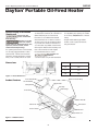
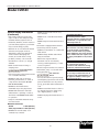
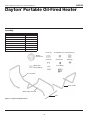
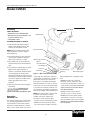
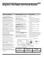
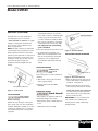
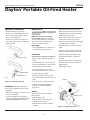
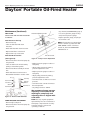
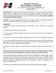
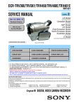
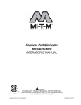
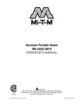
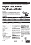
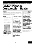
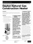
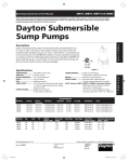
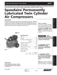
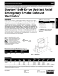
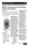
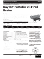
3VE53C
Operating Instructions & Parts Manual
Please read and save these instructions. Read carefully before attempting to assemble, install, operate or maintain the product described.
Protect yourself and others by observing all safety information. Failure to comply with instructions could result in personal injury and/or
property damage! Retain instructions for future reference.
Dayton Portable Oil-Fired
Heater
®
Description
Dayton Model 3VE53C heater is a 400,000 BTU/Hr heater. This heater uses 1-K
Kerosene for combustion, and electricity to run the fan. It is primarily intended for
temporary heating of well ventilated buildings under construction, alteration, or
repair. This heater may be used in agricultural, industrial and commercial
environments.
Specifications
ELECTRICAL SPECIFICATIONS
Model
Electrical Input
Amperage
Fuse
Spark Plug Gap
3VE53C
120V, 60 Hz
3
250V/8 amp
.01” (2.5mm)
Figure 1 – Model 3VE53C
GENERAL SPECIFICATIONS
Model
Type of
Fuel
Input
Rating
Pump
Pressure
Fuel Tank
Capacity
Fuel
Consumption
Unit Size
LxWxH
Net Weight
Lbs. (kg)
3VE53C
1-K Kerosene
400,000 BTU/Hr
130 PSI
24.0 Gallons
3.0 Gal/Hr
53” x 30” x 36”
150 (68kg)
Table of Contents
Page
Description . . . . . . . . . . . . . . . . . . . . . . . 1
Specifications . . . . . . . . . . . . . . . . . . . . . 1
Introduction . . . . . . . . . . . . . . . . . . . . . . 1
Unpacking . . . . . . . . . . . . . . . . . . . . . . . 1
General Safety Information . . . . . . . 1-3
Product Features . . . . . . . . . . . . . . . . . . 2
Assembly . . . . . . . . . . . . . . . . . . . . . . . 4-5
Operation . . . . . . . . . . . . . . . . . . . . . . 5-8
Kerosene (1-K or
Number 1 Fuel Oil). . . . . . . . . . . . . . . . 5
Overview of Heater Design . . . . . . . . . 6
Fueling Your Heater . . . . . . . . . . . . . . 6
Long-Term Storage. . . . . . . . . . . . . . 7-8
Maintenance . . . . . . . . . . . . . . . . . . . 8-10
Wiring Diagram . . . . . . . . . . . . . . . . . . 11
Repair Parts Illustration . . . . . . . . . . . . 12
Repair Parts List . . . . . . . . . . . . . . . . . . 13
Troubleshooting Chart . . . . . . . . . . 14-15
Warranty Information . . . . . . . . . . . . . 16
Introduction
Please read this USER'S MANUAL
carefully. It will show you how to
assemble, maintain and operate this
heater safely and efficiently to obtain
the full benefits of its many features.
Consumer: retain these instructions for
future reference.
Unpacking
1. Remove all packing items applied to
heater for shipment.
2. Remove all items from carton.
3. Check all items for shipping damage.
If heater is damaged, promptly inform
dealer where you purchased heater.
Indicates a potentially hazardous
situation which, if not avoided, COULD
result in death or serious injury.
Indicates a potentially hazardous
situation which, if not avoided, MAY
result in minor or moderate injury.
Before using this
heater, please read
this USER'S MANUAL very carefully. This
USER'S MANUAL has been designed to
instruct you as to the proper manner in
which to assemble, maintain, store, and
most importantly, how to operate the
heater in a safe and efficient manner.
Never leave the
heater unattended
while burning!
General Safety Information
Indicates an imminently hazardous
situation which, if not avoided, WILL
result in death or serious injury.
Form 5S4857
Printed in Korea
09663
0806/234/VCPVP
PIN008
08/06
®
3VE53C
Dayton Operating Instructions and Parts Manual
Dayton Portable Oil-Fired Heater
®
a rotten egg odor during the operation
of the heater. However, #1 or #2 fuel oil
(diesel fuel) may also be used if 1-K
kerosene is not available. Be advised
that these fuels do not burn as clean as
1-K kerosene, and care should be taken
to provide more fresh air ventilation to
accommodate any added contaminants
that may be added to the heated space.
Use of #1 or #2 fuel oil will require
increased maintenance of unit.
General Safety Information
(Continued)
Never leave the
heater unattended
while burning!
Improper use of this
heater can result in
serious injury or death from burns, fire,
explosion, electrical shock, and/or
carbon monoxide poisoning.
For optimal performance of this heater,
it is strongly suggested that 1-K kerosene be used. 1-K kerosene has been
refined to virtually eliminate contaminants, such as sulfur, which can cause
areas! Provide at least a three square
foot (2,300 sq cm) opening of outside
air for every 100,000 BTU/hr of heater
rating.
- People with breathing problems
should consult a physician before
using the heater.
Risk of indoor air
pollution!
- Use this heater only in well ventilated
Dimensions
36”
Dimension
53”
30”
H
36”
L
53”
W
30”
Figure 2 – Heater Dimensions
Product Features
Front Handle
Extension Cord Wrap
Hot Air Outlet
Upper Shell
Safety Guard
Fuel Cap
Fuel Gauge
Lower Shell
Rear Handle
Side Cover
Fan Guard
Control Panel
Fuel Tank
Power Cord
Drain Bolt
Figure 3 – 3VE53C Features
2
Dayton Operating Instructions and Parts Manual
Model 3VE53C
General Safety Information
(Continued)
- NEVER use duct work in front or at
rear of heater.
- Carbon Monoxide Poisoning: Early
signs of carbon monoxide poisoning
resemble flu-like symptoms such as
headaches, dizziness, and/or nausea. If
you have these symptoms, your heater
may not be working properly.
- NEVER move or handle heater while
still hot.
- Get fresh air at once! Have the heater
serviced. Some people are more
affected by carbon monoxide than
others. These include pregnant
women, those with heart or lung
problems, anemia, or those under
the influence of alcohol, or at high
altitudes.
- Never use this heater in living or
sleeping areas.
Risk of Burns/Fire/
Explosion!
- Use 1-K kerosene in this heater. #1 fuel
oil is a suitable substitute.
- NEVER use fuels such as gasoline,
benzene, paint thinners, or other oil
compounds in this heater (RISK OF
FIRE OR EXPLOSION).
- NEVER use this heater where
flammable vapors may be present.
- NEVER refill the heater's fuel tank
while heater is operating or still hot.
This heater is EXTREMELY HOT while
in operation.
- NEVER transport heater with fuel in its
tank.
This heater is equipped with a thermostat and may start at any time.
- ALWAYS locate heater on a stable and
level surface.
- ALWAYS keep children and animals
away from heater.
- Bulk fuel storage should be a
minimum of 25 ft. from heaters,
torches, portable generators, or other
sources of ignition.
All fuel storage should be in accordance
with federal, state, or local authorities
having jurisdiction.
Risk of Electric
Shock!
- Use only the electrical power (voltage
and frequency) specified on the model
plate of the heater. Use only a threeprong, grounded outlet and extension
cord.
CALIFORNIA RESIDENTS:
This heater produces carbon
monoxide, which is listed by the State
of California as a reproductive toxin
under Proposition 65.
MASSACHUSETTS RESIDENTS:
Massachusetts state law prohibits the
use of this heater in any building
which is used in whole or in part for
human habitation. Use of this heating
device in Massachusetts requires local
fire dept. permit (M.E.L.C. 148, Section
10A).
CANADIAN RESIDENTS:
Use of this heater shall be in
accordance with authorities having
jurisdiction and CSA Standard B139.
NEW YORK CITY RESIDENTS:
For use only at construction sites in
accordance with applicable NYC codes
For approval numbers contact your
local Grainger Branch.
- ALWAYS install the heater so that it is
not directly exposed to water spray,
rain, dripping water, or wind.
- ALWAYS unplug the heater when not
in use.
- Keep all combustible materials away
from this heater.
Minimum Clearances
Outlet
8 feet (250 cm)
Sides, Top and Rear 4 feet (125 cm)
- NEVER block air inlet (rear) or air
outlet (front) of heater.
®
3
3VE53C
Dayton Operating Instructions and Parts Manual
Dayton Portable Oil-Fired Heater
®
Assembly
Model
3VE53C
Wheel Support Frame
Wheels and Axle
Wheel Caps
Front Handle
Rear Handle
Cord Wraps
Screws, Nuts and Washers
Cotter Pins and Bushings
Yes
Yes
Yes
Yes
Yes
Yes
Yes
Yes
Screws (L)
Flat Washers (S) Flat Washers (L)
Wheels
(Pneumatic)
Screws (S)
Wheel Caps
(Black Rubber)
Nuts
Cottern Pins
Bushings
Cord Wraps
Front Handle
Rear Handle
Wheel Support Frame
Axle
Figure 4 – Component Identification
4
Dayton Operating Instructions and Parts Manual
Model 3VE53C
Assembly
Cord Wrap
TOOLS REQUIRED
• MEDIUM PHILLIPS SCREWDRIVER
• OPEN OR ADJUSTABLE WRENCH, USE
US (INCH) SCREWS NUTS
Screw (L)
Safety Guard
• LONG NOSE PLIERS
Screw (S)
ASSEMBLING WHEEL & HANDLE
1. Slide axle through wheel support
frame. Install wheel bushings, flat
washers (S) and wheel on axle.
NOTE: When installing wheels, tube
valve should face out from support
frame (Figure 5).
2. Place flat washers (L) and cotter pins
on axle ends and bend cotter pins
with long nose pliers to secure.
3. Place wheel cap on flat washers (L)
and put wheel cap in flat washers (L)
end.
4. Place heater on wheel support frame.
Make sure air inlet end (rear) of
heater is over wheels. Align the holes
on fuel tank flange. Insert screws
through handles (front and rear), fuel
tank flange, and wheel support frame
as shown in Figure 5 and attach nut
finger tight after each screw is
inserted.
5. After all screws are inserted, tighten
nuts firmly.
DO NOT operate
heater without
support frame fully assembled to tank.
Operation
KEROSENE (1-K)
For optimal performance of this heater,
it is strongly suggested that 1-K kerosene be used. 1-K kerosene has been
refined to virtually eliminate contaminants, such as sulfur, which can cause a
Fuel Tank Flange
Air Inlet
Nut
Wheel Support Frame
Wheel
(Semi-Pneumatic)
Flat Washer (L)
Axle
Cotter Pin
Flat Washer (S)
Wheel Cap
Bushing
Wheel Tube Valve
Figure 5 – Wheel and Handle Assembly
rotten egg odor during the operation
of the heater. However, #1 or #2 fuel oil
(diesel fuel) may also be used if 1-K
kerosene is not available. Be advised
that these fuels do not burn as clean as
1-K kerosene, and care should be taken
to provide more fresh air ventilation to
accommodate any added contaminants
that may be added to the heated space.
NOTE: Kerosene should only be stored
in a blue container that is clearly
marked “kerosene”. Never store
kerosene in a red container. Red
containers are associated with gasoline.
- NEVER store kerosene in the living
space. Kerosene should be stored in a
well ventilated area outside the living
area.
- NEVER use fuel such as gasoline,
benzene, alcohol, white gas, camp
stove fuel, paint thinners or other oil
compounds in this heater (THESE ARE
VOLATILE FUELS THAT CAN CAUSE A
FIRE OR EXPLOSION).
- NEVER store kerosene in direct
sunlight or near a source of heat.
- NEVER use kerosene that has been
stored from one season to the next.
Kerosene deteriorates over time. OLD
KEROSENE WILL NOT BURN PROPERLY
IN THIS HEATER.
®
5
3VE53C
Dayton Operating Instructions and Parts Manual
Dayton Portable Oil-Fired Heater
®
Operation (Continued)
- Use 1-K kerosene in this heater. #1
fuel is a suitable substitute.
OVERVIEW OF HEATER DESIGN
Fuel System: This heater is equipped
with an electric magnet pump that
forces fuel through the fuel line
connected to the fuel intake, and then
through a nozzle in the burner head.
This fuel is then sprayed into the
combustion chamber in a fine mist.
“SureFire Ignition”: The electronic
ignitor sends voltage to a specially
designed spark plug. The spark plug
ignites the fuel and air mixture.
The Air System: The heavy duty motor
turns a fan that forces air into and
around the combustion chamber. Here,
the air is heated and then forced out
the front of the heater.
THE SAFETY SYSTEM
Temperature Limit Control: This
heater is equipped with a Temperature
Limit Control designed to turn the
heater off should the internal
temperature rise to an unsafe level. If
this device activates and turns your
heater off, it may require service.
Flame-Out Sensor: Utilizes a photocell
to monitor the flame in burn chamber
during normal operation. It will cause
the heater to shut off should the burner
flame extinguish.
FUELING YOUR HEATER
NEVER fill the heater fuel tank in the
living space: fill the tank outdoors.
TO START HEATER
1. Fill fuel tank with kerosene or No. 1
fuel oil.
2. Attach fuel cap.
3. Plug power cord into three-prong,
grounded extension cord. Extension
cord must be at least six feet long.
Do not overfill your heater and be sure
heater is leveled.
Extension Cord Wire Size Requirements:
• 6 to 10 feet long, use 14 AWG
conductor.
Never refill fuel
tank when heater
is operating or still hot.
• 101 to 200 feet long, use 12 AWG
conductor.
IMPORTANT: REGARDING FIRST
IGNITION OF HEATER. The first time you
light the heater, it should be done
OUTDOORS. This allows the oils, etc.
used in manufacturing the heater to
burn off outside.
VENTILATION
Risk of indoor air
pollution. Use heater
only in well ventilated areas.
Provide a fresh air opening of at least 3
square feet. (2,800 sq. cm.) for each
100,000 BTU/Hr. rating. Provide extra
fresh air if more heaters are being used.
• 201 to 300 feet long, use 10 AWG
conductor.
• 301 to 400 feet long, use 8 AWG
conductor.
• 401 to 500 feet long, use 6 AWG
conductor.
4. Push “OPERATION BUTTON”. Power
indicator lamp and room temperature
display will light and heater will start.
Push the up and down arrow keys on
the control panel to adjust the
thermostat settings.
Fuse Barrel
Once the temperature falls below the
reset temperature, you will be ale to
start your heater.
Electrical System Protection: This
heater’s electrical system is protected by
a fuse that protects it and other
electrical components from damage.
Fuse is located inside of an in-line “FUSE
BARREL”. If your heater fails to
operate, check this fuse first and replace
as needed. Refer to Specification Chart
on page 1.
Fuse
Operation Button
Figure 6 – Overview of Heater Design
MODELS
Internal Shut-Off Temp.
+/-10 Degrees
Reset Temp.
+/-10 Degrees
3VE53C
140°F / 60°C
130°F / 54°C
6
Dayton Operating Instructions and Parts Manual
Model 3VE53C
Operation (Continued)
If heater does not start, the thermostat setting may be too low. Push
“TEMP CONTROL UP ARROW” to higher
setting to start heater. If heater still
does not start, see Troubleshooting
Chart on page 14-15.
NOTE: The major electrical components
of this heater are protected by a circuit
breaker (fuse) mounted to the power
switch. If your heater fails to start, check
this first and replace as necessary. You
should also check your power source to
insure that proper voltage and
frequency are being supplied to the
heater.
1. Push “OPERATION BUTTON”, This will
cause heater flame to go out. The
motor will continue to run during the
cooling cycle. This allows the fan to
cool the combustion chamber. When
the cooling cycle (approx. 2 minutes)
is finished, the motor will stop. Do
not unplug heater until cooling
cycle is finished.
2. Disconnect heater from power source.
3. To temporarily stop heater, set
thermostat at a temperature lower
than air around heater. Heater will
cycle back on if air temperature
around heater matches thermostat
setting.
Figure 8 – Electrical Outlet
LONG-TERM STORAGE OF HEATER
TO RESTART HEATER
DO NOT restart
heater until
cooling cycle is finished.
Operation
Button
Temp Control Buttons
Figure 7 – Control Parts
The cooling cycle cools the combustion
chamber.
Figure 9 – Drain Bolt Removal
1. Wait until cooling cycle is finished
after stopping heater.
1. Remove drain nut from rear bottom
side of fuel tank by unscrewing nut
and drain. See Figure 9.
2. Repeat steps under TO START
HEATER.
ELECTRICAL OUTLET
Shock Hazard!
TO STOP HEATER
Never unplug
heater while
heater is running.
Heater must go through cooling cycle.
The cooling cycle cools the combustion
chamber. Damage to heater can occur if
combustion chamber is not cooled. Do
not restart heater until cooling cycle is
complete.
Drain Bolt
- Never plug in an appliance with more
than 5amp rating in this outlet.
- Always keep outlet covered when not
in use.
2. Using a small amount of kerosene,
swirl and rinse the inside of the tank.
NEVER MIX WATER WITH KEROSENE,
as it will cause rust inside the tank.
Pour the kerosene out, making sure
that you remove it all.
IMPORTANT: Do not store kerosene
over summer for use during next
heating season. Using old fuel may
damage heater.
- 120V 5amp max (non fused).
®
7
3VE53C
Dayton Operating Instructions and Parts Manual
Dayton Portable Oil-Fired Heater
®
Operation (Continued)
Never service heater
while it is plugged in
3. Reinstall drain bolt as follows:
- Insert bolt’s seal head fully into drain
hole so that flange is flush to tank’s
bottom. See Figure 10.
- Insert seal cap fully into head hole so
that cap flange is flush to head flange.
(See Figure 10).
- Remove lead wire from spark plug.
Maintenance
or while hot!
NOTE: USE ORIGINAL EQUIPMENT
REPLACEMENT PARTS. Use of thirdparty or other alternate components
will void warranty and may cause
unsafe operating conditions.
FUEL TANK
- Flush every 200 hours of operation or
as needed (See Storage, page 7).
Drain Bolt
- Remove spark plug from burner head.
- Carefully remove nozzle from burner
head using socket wrench.
- Blow compressed air through face of
nozzle (This will remove any dirt).
- Inspect nozzle for damage. If damaged
or clogged, replace nozzle.
- Make sure plug is in place on burner
head.
- Reinstall nozzle into burner head and
tighten firmly (175-200 inch-pounds).
FAN BLADES
- Reinstall spark plug in burner head.
CLEAN EVERY SEASON OR AS NEEDED.
- Attach burner head to combustion
chamber.
- Remove upper shell (See air intake
filter).
- Attach spark plug wire to spark plug
- Use Allen wrench to loosen set screw
which holds fan blade to motor shaft.
- Attach fuel line to burner head and
tighten firmly.
- Slip fan blade off motor shaft.
- Replace upper shell.
- Clean fan blade using soft cloth
moistened with kerosene or solvent.
Drain Nut
Drain Bolt
- Dry fan blade thoroughly.
- Reinstall fan blade to motor shaft.
(Bottom-Front of Fuel Tank)
- Place fan hub flush with end of motor
shaft.
Figure 10 – Drain Bolt Reinstall
- Place set screw on flat end of shaft.
IMPORTANT: Reinstall bolt fully into
hole in tank; otherwise it will not seal
completely.
- Make sure storage place is free of dust
and corrosive fumes.
- Store the heater in the original box
with the original packing material and
keep USER'S MANUAL with heater.
Nozzle
- Tighten screw firmly (40-50 inch
pounds/ 4.5-5.6 N-m). Reinstall
upper shell
NOZZLE
Remove dirt in nozzle as needed
(see page 12).
photocell
- Remove upper shell.
- Remove fuel line B from burner
assembly by using wrench.
- Remove burner head from burner
assembly.
8
Figure 11 – Nozzle Replacement
Dayton Operating Instructions and Parts Manual
Model 3VE53C
Maintenance (continued)
Spark Plug
PHOTOCELL
Photocell
CLEAN PHOTOCELL ANNUALLY OR AS
NEEDED.
- Remove upper shell.
- Remove fan (See fan blades).
- Remove photocell from its mounting
bracket
- Clean photocell lens with cotton swab.
Nozzle
Figure 12 – Nozzle
TO REPLACE: Remove side cover near
Operation switch.
- Attach ignitor wire to spark plug.
- Disconnect wires from Operation
switch and remove photocell.
- Attach fuel and air line hoses to
burner head.
- Reinstall fan blade and upper shell.
SPARK PLUG
CLEAN AND REGAP EVERY 600 HOURS
OF OPERATION OR REPLACE AS NEEDED.
- Remove upper shell.
- Disconnect wires from circuit board
and remove side cover.
Figure 15 – Photocell Replacement
- Install new photocell and attach wires
to circuit board.
- Replace switch wires to operation
switch and side cover.
- Replace fan and upper shell.
- Remove spark plug wire from spark
plug (See Figure 13).
- Remove spark plug from burner head
using medium Phillips screwdriver.
- Clean and regap spark plug electrodes
to 0.1” (2.5 mm) gap.
- Reinstall spark plug into burner head.
- Attach spark plug wire to spark plug.
- Reinstall upper shell.
Spark Plug
Figure 14 – Photocell Lead Wire
Nozzle
Figure 13 – Spark Plug Replacement
®
9
3VE53C
Dayton Operating Instructions and Parts Manual
Dayton Portable Oil-Fired Heater
®
- Stop heater (See OPERATION, page 7).
Maintenance (Continued)
FUEL FILTER
CLEAN TWICE PER HEATING SEASON OR
AS NEEDED.
Pressure adjusting Screw
used, remove pressure gauge.
- Replace pressure gauge, and plug in
end of filter cover.
Fuel filter A on fuel cap
NOTE: If heater does not ignite when
heater is turned on, please turn AIR
VENT SCREW counter clockwise to
release air, then turn OPERATION
SWITCH back on.
- Remove fuel cap.
- Take out fuel filter with clean
kerosene.
- Wash fuel filter with clean kerosene.
- Replace fuel filter on fuel tank.
- Replace fuel cap on fuel tank.
Air vent Screw
Fuel filter B on fuel line
(See Figure 16)
Figure 17 – Pump Pressure Adjustment
- Remove fuel line A from fuel pump by
using wrench.
- Take out fuel line from fuel tank by
pulling out fuel filter gasket.
- Remove fuel filter assembly from fuel
line
- Wash fuel filter in clean kerosene.
- Reassemble fuel filter in reverse order.
Fuel Cap
Fuel Line A
Fuel Line A
Gasket
Fuel Cap
Gasket
Fuel Filter A
Fuel Filter B
Figure 16 – Remove Tank Fuel Filter
PUMP PRESSURE ADJUSTMENT
- Remove right side panel.
- Remove fuel line A from fuel pump by
using wrench.
If accessory pressure gauge is being
- Replace pressure gauge at outlet of
fuel pump.
- Adjust pump pressure by turning
pressure adjustment screw
- Replace pressure gauge at outlet of
fuel pump.
- Adjust pump pressure by turning
pressure adjustment screw.
- Turn relief valve clockwise to increase
pressure.
- Turn relief valve counterclockwise to
decrease pressure.
- Set pump pressure to 130 PSI.
We recommend pump pressure
adjusting is not needed if red
marking on pump body and
adjusting screw is aligned with
each other.
NOTE: Use only original equipment
replacement parts. Use of alternate or
third party components will void any
warranty and may cause unsafe
operating conditions.
10
Dayton Operating Instructions and Parts Manual
Model 3VE53C
Wiring Diagrams
®
11
3VE53C
Dayton Operating Instructions and Parts Manual
For Repair Parts, call 1-800-323-0620
24 hours a day – 365 days a year
Please provide following information:
-Model number
-Serial number (if any)
-Part description and number as shown in parts list
Address parts correspondence to:
Grainger Parts
P.O. Box 3074
1657 Shermer Road
Northbrook, IL 60065-3074 U.S.A.
44
27
Figure 18 – Repair Parts Illustration for Portable Oil-Fired Heater
12
Dayton Operating Instructions and Parts Manual
Model 3VE53C
Repair Parts List for Portable Oil-Fired Heater
Ref.
No.
Description
Part
No.
1
2
3
4
5
6
7
8
9
10
11
12
13
14
15
16
17
18
19
20
21
22
23
24
25
Upper Shell
Chamber Assembly
Lower Shell
Baffle Bracket Rear
Fuel Tank Assembly
Right Side Cover
PCB Case Lower
PCB Case Upper
P.C.B. Assembly
Air Baffle Plate
Bushing Grommet (S)
Fuel Cap Assembly
Fuel Filling Filter
Fuel Line Assembly (A)
Fuel Gauge Assembly
Magnetic Pump Assembly
Ignitor
Cord Bushing
Power Cord Assembly
Wheel Support Frame
Wheel Axle
Pneumatic Wheel
Split Pin
Wheel Bushing
Flat Washer (A)
70-001-1401
70-011-0600
70-001-1402
70-001-0608
70-002-0400
70-008-0500
70-027-0702
70-027-0703
70-027-0800
70-012-0100
70-017-0200
70-006-0200
70-006-0300
70-036-0700
70-007-0200
70-020-0700
70-037-0700
70-033-0200
70-034-0300
70-064-0100
70-041-0303
70-041-0110
70-041-0107
70-041-0109
70-041-0105
Qty.
1
1
1
4
1
1
1
1
1
1
5
1
1
1
1
1
1
1
1
1
1
2
2
2
2
Ref.
No.
Description
Part
No.
26
27
28
29
30
31
32
33
34
35
36
37
38
39
40
41
42
43
44
45
46
47
48
49
Wheel Cap
Fan Guard
Left Side Cover
Socket Cover
Electrical Outlet Assembly
Bushing Grommet (L)
Thermostat
Thermostat Bracket
Rubber Bushing
Burner Blower Fan Assembly
Photocell Assembly
Air Control Head Assembly
Spark Plug
Nozzle
Burner Motor Assembly
Fan Fixing Screw M8x8
Fan Assembly
Air Motor Assembly
Motor Supporter
Safety Guard
Front Handle
Rear Handle
Cord Wrap
Drain Bolt
70-041-1111
70-016-0300
70-009-0500
70-030-0100
70-029-0100
70-018-0200
70-019-0500
70-019-0501
70-018-0300
70-063-0300
70-016-0150
70-014-0701
70-052-0400
70-015-0750
70-063-0200
70-024-0700
70-021-0700
70-020-0407
70-065-0100
70-042-0300
70-043-0300
70-032-0200
70-002-0107
Qty.
2
1
1
1
1
1
1
1
1
1
1
1
1
1
1
1
1
1
1
1
1
1
2
1
®
13
3VE53C
Dayton Operating Instructions and Parts Manual
Dayton Portable Oil-Fired Heater
®
Troubleshooting Chart
Symptom
Possible Cause(s)
Heater ignites but Main
PCB assembly
shuts heater off after
a short period of time
(Lamp is flickering)
E1
Heater will not ignite, but
motor runs for a short
period of time (Lamp is
flickering)
E1
Fan does not turn when
heater is plugged in.
Corrective Action
1. Wrong pump pressure
1. See Pump Pressure Adjustment, Page 10
2. Dirty fuel filter
2. See Fuel Filter, Page 10
3. Dirt in nozzle
3. See Nozzle, Page 8
4. Dirty photocell lens
4. Clean Photocell Lens, Page 9
5. Photocell assembly not properly installed
(not seeing flame)
5. Make sure photocell boot is properly seated
in bracket (See page 9)
6. Bad electrical connection between
photocell and Main PCB assembly
6. Check electrical components (See Wiring
Diagrams, Page 11)
7. Defective photocell
7. Replace Photocell, Page 9
1. No fuel in tank
1. Fill tank with kerosene
2. Wrong pump pressure
2. See Pump Pressure Adjustment, Page 10
3. Carbon deposits on spark plug and/or
improper gap
3. See Spark Plug, Page 9
4. Dirty fuel filter
4. See Fuel Filter, Page 10
5. Dirt in nozzle
5. See Nozzle, Page 8
6. Water in fuel tank
6. Flush fuel tank with clean kerosene, page 7
7. Bad electrical connection between ignitor
and Main PCB assembly
7. Check electrical connections (See Wiring
Diagrams, Page 11)
8. Ignitor Wire not attached to spark plug
8. Attach ignitor wire to spark plug (See Spark
Plug, Page 9)
9. Defective ignitor
9. Replace ignitor
1. Thermostat setting too low
1. Adjust thermostat to a higher setting
2. Poor electrical connection between motor
and Main PCB assembly
2. Check electrical connections (See Wiring
Diagrams, Page 11)
1. Switch Failure
1. Replace Switch
2. Short Circuit
2. Check Wiring and connection
E1 or E2
E3
14
Dayton Operating Instructions and Parts Manual
Model 3VE53C
Troubleshooting Chart (Continued)
Symptom
Possible Cause(s)
Corrective Action
Sensor disconnected
A. Check limit control thermostat
E4
B. Check sensor connection
E5
Temperature limit safety device is
overheated
1. Poor Combustion
Wait until unit cools down
1. Poor Combustion
- Flames extending beyond heater
- Low heat output
- Align the red mark between the air screw and
pump body
Other Problems
2. Power Failure
2. Power Failure
- No power supply to heater
- Check / Replace Fuse
®
15
Dayton Operating Instructions and Parts Manual
3VE53C
Dayton Portable Oil-Fired Heater
®
LIMITED WARRANTY
DAYTON ONE-YEAR LIMITED WARRANTY. Dayton® Portable Oil-Fired Heater, Model covered in this manual, is warranted by Dayton
Electric Mfg. Co. (Dayton) to the original user against defects in workmanship or materials under normal use for one year after date of
purchase. Any part which is determined to be defective in material or workmanship and returned to an authorized service location, as
Dayton designates, shipping costs prepaid, will be, as the exclusive remedy, repaired or replaced at Dayton’s option. For limited warranty
claim procedures, see PROMPT DISPOSITION below. This limited warranty gives purchasers specific legal rights which vary from jurisdiction to
jurisdiction.
LIMITATION OF LIABILITY. To the extent allowable under applicable law, Dayton’s liability for consequential and incidental damages is
expressly disclaimed. Dayton’s liability in all events is limited to and shall not exceed the purchase price paid.
WARRANTY DISCLAIMER. Dayton has made a diligent effort to provide product information and illustrate the products in this literature
accurately; however, such information and illustrations are for the sole purpose of identification, and do not express or imply a warranty
that the products are MERCHANTABLE, or FIT FOR A PARTICULAR PURPOSE, or that the products will necessarily conform to the illustrations
or descriptions. Except as provided below, no warranty or affirmation of fact, expressed or implied, other than as stated in the “LIMITED
WARRANTY” above is made or authorized by Dayton.
PRODUCT SUITABILITY. Many jurisdictions have codes and regulations governing sales, construction, installation, and/or use of products for
certain purposes, which may vary from those in neighboring areas. While Dayton attempts to assure that its products comply with such
codes, it cannot guarantee compliance, and cannot be responsible for how the product is installed or used. Before purchase and use of a
product, review the product applications, and all applicable national and local codes and regulations, and be sure that the product,
installation, and use will comply with them.
Certain aspects of disclaimers are not applicable to consumer products; e.g., (a) some jurisdictions do not allow the exclusion or limitation of
incidental or consequential damages, so the above limitation or exclusion may not apply to you; (b) also, some jurisdictions do not allow a
limitation on how long an implied warranty lasts, consequentially the above limitation may not apply to you; and (c) by law, during the
period of this Limited Warranty, any implied warranties of implied merchantability or fitness for a particular purpose applicable to consumer
products purchased by consumers, may not be excluded or otherwise disclaimed.
PROMPT DISPOSITION. Dayton will make a good faith effort for prompt correction or other adjustment with respect to any product which
proves to be defective within limited warranty. For any product believed to be defective within limited warranty, first write or call dealer
from whom the product was purchased. Dealer will give additional directions. If unable to resolve satisfactorily, write to Dayton at address
below, giving dealer’s name, address, date, and number of dealer’s invoice, and describing the nature of the defect. Title and risk of loss pass
to buyer on delivery to common carrier. If product was damaged in transit to you, file claim with carrier.
Manufactured for Dayton Electric Mfg. Co., 5959 W. Howard St., Niles, Illinois 60714 U.S.A.
Manufactured for Dayton Electric Mfg. Co.
Niles, Illinois 60714 U.S.A.
®