1
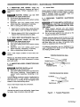
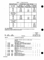
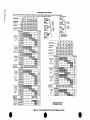
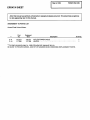
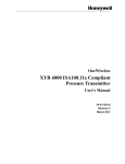
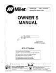
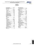
FORM: OM-i 559
March 1988
Effective With Style No. JJ-23
Millerfi
MODEL
MTT-1512HR
MTT-1525HR
MTT-1512NR
ALE COpy
~ETURN TO
FOLDER
MTT-1525NR
MTF-1512VHR
MU-i 525VH R
MU-1512VNR
MU-i 525 VN R
MU-i 512 H F
MU-1525HF
MU-1512NF
MU-i 525N F
MU-1512VHF
MU-i 525 VH F
MU-1512VNF
MU-i 525 VN F
OWNERS
IMPORTANT
MANUAL
Read and understand the entire contents of both this
manual and the power source manual used with this unit, with special
emphasis on the safety material throughout both manuals, before in-
maintaining this equipment. This unit and these
instructions are for use only by persons trained and experienced in the
safe operation of welding equipment. Do not allow untrained persons to
stalling, operating,
install, operate,
not
or
or
Miller Electric Mfg.Co.
~o. Box 1079
Appleton,
WI 54912 USA
Te1 414-734-9821
maintain this unit. Contact your distributor if you do
fully understand these instructions.
PRINTED IN U.S.A.
ADOmONAL COPY PRICE 35 CENTS
LIMITED WARRANTY
EFFECTIVE: FEBRUARY 16. 1988
supersedes
This warranty
all previous MILLER warranties and
is
exclusive with
or
implied.
or, where authorized in
a two
to
specified below, Millers warranty does
components
year, such
having
normal useful life of less than
one
cases,
(3)
or
failure, Miller shall instruct the claimant
on
the warranty
claim procedures to be followed.
(1)
spot welder tips, relay and contactor points,
MILLERMATIC parts that come in contact with the welding
wire including nozzles and nozzle insulators where failure does
not
appropriate
of the goods at Customers risk and expense. MILLERs
option of repair or replacement will be F.O.B., Factory, at
Appleton, Wisconsin, or F.O.B., at a MILLER authorized service
facality, therefore, no compensation for transportation costs of
any kind will be allowed. Upon receipt of notice of apparent
apply
not
in
return
year warranty.
as
writing by Miller
the reasonable cost of repair or replacement at an authorized
Miller service station or (4) payment of or credit for the purchase
price (less reasonable depreciation based upon actualuse) upon
defect
Except
~
expressed
Equipment furnished by Miller is free from defect in workmanship and material as of the time and place of delivery by Miller.
No warranty is made by Miller with respect to engines, trade
accessories or other items manufactured by others. Such
engines, trade accessories and other items are sold subject to
the warranties of their respective manufacturers, if any
All
engines are warranted by their manufacturer for one year from
date of original purchase, except Tecumseh engines which
have
as
result from defect in
workmanship
or
ANY EXPRESS WARRANTY NOT PROVIDED HEREIN AND
ANY IMPUED WARRANTY, GUARANTY OR REPRESENTA
T1ON AS TO PERFORMANCE, AND ANY REMEDY FOR
BREACH OF CONTRACT WHICH, BUT FOR THIS PROVISION,
material.
~
Miller shall be required to honorwarranty claims on warEquipment in the event of failure resulting from a defect
within the following periods from the date of delivery of Equip-
~J
ment to the
~
or warranties
In the case of Millers breach of warranty or any other duty
with respect to the quality of any goods, the exclusive remedies
therefore shall be, at Millers option (1) repair or (2) replacement
.
$J
P~
other guarantees
LIMITED WARRANTY
Subject to the terms and conditions hereof, Miller Electric Mfg. Co., Appleton, Wisconsin
warrants to its Distributor/Dealer that all new and unused
-
~
no
MIGHT ARISE BY IMPLICATION, OPERATION OF LAW,
CUSTOM OF TRADE OR COURSE OF DEALING, INCLUDING
ANY IMPUED WARRANTY OF MERCHANTABIUTY OR OF
FITNESS FOR PARTICULAR PURPOSE, WITH RESPECT TO
ranted
original
user:
ANY AND ALL EQUIPMENT FURNISHED BY MILLER IS EX
~f
~
1. Arc welders, p~r sources, robots, and components
2. Load banks
3.
Original main
(labor
i.)
~J
~
~
5. All other Millermatic Feeders
6. Replacement or repair parts, exclusive of labor
7. Batteries
that Miller is notified in
of the date of such failure.
provided
!~
~
fl
power rectifiers
CLUDED AND DISCLAIMED BY MILLER.
1 year
1 year
3 years
EXCEPT
1 year
only)
4. Allweldingguns,feeder/gunsandtorches
-
.
WRITING,
90days
60
BY
MILLER
INTENDED
IN
FOR
ULTIMATE PURCHASE BY COMMERCIAL/INDUSTRIAL
USERS AND FOR OPERATION BY PERSONS TRAINED AND
EXPERIENCED IN THE USE AND MAINTENANCE OF
WELDING EQUIPMENT AND NOT FOR CONSUMERS OR
CONSUMER USE. MILLERS WARRANTIES DO NOT EXTEND
TO, AND NO RESELLER IS AUTHORIZED TO EXTEND
MILLERS WARRANTIES TO, ANY CONSUMER.
1 year
..
AS EXPRESSLY PROVIDED
MILLER
ARE
PRODUCTS
days
6 months
writing within thirty (30) days
As a matter at general policy ony, Miller may honor claims
submitted by the original user within the foregoing periods.
-.
......
..-...
-...
.
SECTION 1
-
UNSAFE PROCEDURES OR PRAC
WARNING
SAFETY RULES
PROTECT EYES AND SKIN
1 -3.
FROM ARC
_________
serious personal injury or death.
Read, understand, and follow ALL of these safety
rules before installing, operating, or servicing this
TIGES
can cause
equipment.
Be
sure
that all end
users
of this
the
equipment,
RAYS; PROTECT EARS FROM NOISE
Arc rays from the welding process produce intense heat
and strong ultraviolet rays that can burn eyes and skin.
Noise from some processes can damage hearing.
operator and helpers, read and understand these
safety
1
a welding helmet fitted with a proper filter
lens (see ANSI Z49.1 for detailed information).
a.
Wear
b.
Use
rules.
1. PREVENT ELECTRIC SHOCK
-
Touching
the body
Do not touch live electrical parts.
b.
Do not work in wet
c.
Wear
or
damp
dry insulating gloves and body protection.
clothing
and foot
d.
Always wear safety glasses
1 -4.
barriers to protect
or
glare.
Wear protective
work
areas.
screens
c.
determined by the path and amount of current through
the body. Therefore:
a.
protective
others from flash and
live electrical parts can cause severe burns to
or fatal shock. Severity of electrical shock is
or
protection.
safety goggles in
a
area.
PREVENT FIRES AND BURNS
The hot
workpiece, hot equipment, other hot metal,
arc sparks can cause fires and burns.
spatter, and
d.
e.
f.
g.
h.
Disconnect all power before installing
ing this equipment.
Turn off all
Properly
source according
applicable codes.
ground
the
Do not wrap cabes
cables
damaged
or
poorly spliced.
around your
or
body.
equipment
to
cool before handl
combustible material.
c.
Do not weld
d.
Watch for fire, and keep
e.
Do not touch electrode and any
or circuit at the same time.
j.
Use only well-maintained equipment. Repair
2.
Allow work and
in
near
a
fire
extinguisher
near
by.
For additional information, refer to NFPA Stan
dard 51 B, Fire Prevention in Use of Cutting and
available from the National
Fire Protection Association, Batterymarch Park,
Quincy, MA 02269.
Welding Processes,
grounded object
or
at once.
1
-
b.
protection
ing.
cables
i.
PROVIDE
AND GASES
1
Wear correct eye, face, and body
the work area.
Manual and all
or
replace damaged parts
a.
welding power
to its Owners
Do not use worn
that are too small
servic
not in use.
equipment when
install and
or
PROTECTION
FROM
-
5. PROTECT COMPRESSED GAS CYLINDERS
FUMES
Since gas cylinders
are
normally part of the welding
carefully.
pro
cess, be sure to treat them
Breathing welding
to your
fumes and gases
can
be hazardous
health.
a.
Protect
compressed
gas
cylinders from excessive
heat, mechanical shocks, and
Keep
b.
Use adequate ventilation in the work area to
keep fumes and gases from your breathing zone
b.
and the
general
work
c.
If ventilation is inadequate,
breathing device.
d.
Read the Material
use
an
approved
or
Safety Data Sheets (MSDSs)
manufacturers
instructions
for
Keep cylinders away from
any
welding
or
other
electrical circuits.
d.
the
secure cylinders so that they cannot
tip over by fastening them to a mounting
bracket, wall, or other stationary support.
Install and
fall
area.
c.
and
arcs.
your head out of the fumes.
a.
Never allow
a
welding
electrode to touch any
cylinder.
any
materials used.
aM-i 559
Page
1
PROVIDE
1 -6.
PROTECTION
FOR
SPECIAL
1 -8. ADDITIONAL SAFETY INFORMATION
S ITU ATIO N S
Do not weld
containers or materials which
have held or been in contact with hazardous
substances unless they are properly cleaned and
a.
or Cut
inspected.
painted or plated parts unless
special ventilation is provided to remove highly
b.
Do not weld
or cut
toxic fumes
or
affect pacemakers, keep all
wearers out of the work area. Have
pacemaker
them consult
more
N.W. LeJuene Rd., Miami, FL 33126,
ed to you:
are
Safety in Welding and Cutting
(ANSI)
a.
gases.
Since welding
c.
information on safe practices for setting up
operating electric welding and cutting equipment
and on good working habits, ask your welding equip
ment supplier. The following publications, which are I
available from the American Welding Society, 550
For
and
-
recommend
AWS Z49.1
can
a
doctor before
coming
near
Recommended
b.
Arc
a
Welding
-
Safe Practices for Gas-Shielded
AWS A6.1
welding operation.
c.
PROPER
7. PROVIDE
MAINTENANCE
1
-
EQUIPMENT
-
Improperly maintained equipment can result in poor
most importantly it can cause physical injury
or death through fires or electrical shock. Therefore:
work, but
a.
qualified personnel perform the in
troubleshooting, and maintenance
work. Do not perform any electrical work unless
you are fully qualified.
Always
Safe Practices for the Prepara
tion for Welding and Cutting of Containers and
Piping That Have Held Hazardous Substances
AWS F4.1
Recommended
d.
have
NFPA Standard 516, Fire Prevention in Use of
Cutting and Welding Processes, available from
the National Fire Protection Association, Bat
terymarch Park, Quincy, MA 02269.
stallation,
b.
Before
performing
c.
Maintain cables,
source.
NFPA Standard 70, National Electrical Code,
available from the National Fire Protection
Association, Batterymarch Park, Quincy, MA
02269.
any maintenance work inside
disconnect the power supply
power supply,
form the electrical power
a
e.
f.
grounding wire, connections,
power cord, and power supply in safe working
order. Do not operate any equipment in ques
ANSI Standard Z87.1, Safe Practice for Oc
cupation and Educational Eye and Face Protec
tion, available from the American National
Standards Institute, 1430 Broadway, New York,
.
NY 10018.
tionable condition.
g.
d.
Do not abuse any equipment
Keep equipment away from heat
furnaces,
wet
e.
f.
or
as water puddles,
atmospheres, and incle
conditions such
grease, corrosive
ment weather.
oil
accessories.
sources such as
or
h.
Keep all safety devices, guards, panels, and
covers in position and in good repair.
Use equipment for its intended purpose. Do not
modify it in any manner.
i.
OSHA Standard 29 CFR, Part 1910, Subpart Q,
Welding, Cutting, and Brazing, available from
the Superintendent of Documents, U.S. Govern
ment Printing Office, Washington, DC 20402.
for Safety in
the Cana
from
available
and
Cutting,
Welding
dian Standards Association, 178 Rexdale Blvd.,
Rexdale, Ontario, Canada M9W 1 R3.
CSA Standard W117.2, Code
See also the Standards Booklet Index in the
welding power source Owners Manual.
.
OM-1559
Page
2
SECTION 1
-
INTRODUCTION
Ampere Rating
Model
at
Tungsten
100% Duty Cycle
DCEN: ACHF
Size
Cable
Torch
Cooling
Capacity
£~~h
Body
Method
Weight
Ship
Net
MTT-1512HR
MTT-1512HF
MTr-1512VHF
2.5 lbs.
3.0 lbs.
(1.1 kg)
(1.4 kg)
.
MTT-1512VHR
12.5 ft.
(3.8 m)
Length: 8.0
MTT-1512NR
in.
(203.0 mm)
MTT-1512NF
MTT-1512VNR
Handle Diameter:
.020 thru
MTT1512VNF
MTT-1525HR
3.5 lbs.
kg)
(1.6 kg)
0.9 in. (22.9 mm)
1/8 in.
(0.5 thru
3.2 mm)
150 Amperes
With Argon
3.0 lbs.
(1.4
Weight:
4.5
Air
oz.
(127.6 9)
MTT-1525HF
4.5 lbs.
5.0 lbs.
MTT-1525VHR
MTT-1525VHF
(2.0 kg)
(2.3 kg)
MTT-i 525NF
5.5 lbs~
6.0 lbs.
MTT-1525VNR
MIT-i 525VNF
(2.5 kg)
(2.7 kg)
25 ft.
(7.6 m)
MIT-i 525NR
Rated with Gas Lens Collet
Body
Figure
2
-
The duty cycle of a welding
1. DUTY CYCLE
torch is the percentage of a ten minute period that a
torch can be operated at a given load. This torch is rated
at 100% duty cycle using argon shielding gas. This
2
-
-
means
that the torch
ditions
continuously.
can
be
operated
Do not exceed rated amperage and duty cycle
stated in Figure 2-1.
2 -2. GENERAL INFORMATION AND SAFETY
General
presented
in this manual and
on
various
labels, tags, and plates on the unit pertains to equip
ment design, installation, operation, maintenance, and
troubleshooting which should be read, understood, and
followed for the safe and effective
use
of this equip
ment.
B.
installation,
of
procedures
signal word,
or
2
3. RECEIVING
-
equipment,
this
~ highlights instruc
emphasis to obtain the most
equipment.
Il~I~s]
tions which need special
efficient operation of this
Before installing
HANDLING
packing material from around
-
clean all
unit, and carefully inspect for any damage that may
have occurred during shipment. Any claims for loss or
the
damage that may have occurred in transit must be filed
by the purchaser with the carrier. A copy of the bill of
lading will be furnished by the manufacturer on request
if occasion to file claim arises.
requesting information concerning this equip
ment, it is. essential that Model Description and Style
Numbers of the equipment be supplied. The style
number is located on a label under the torch handle.
When
2
M
T
____________
___________
different levels of hazard.
-
12
25
H
N
R
WARNING
include installation, operation,
____________statements
and maintenance procedures or practices which if not
carefully followed could result in serious personal injury
specifically for
F
V
Miller
TIG/GTAW
Torch
-
-
15
Safety instructions specifically pertaining to this unit ap
pear throughout this manual highlighted by the signal
words WARNING and CAUTION which identify
This torch is
following:
the end of Section 1
Safety Rules.
-
with the Gas Tungsten Arc Welding (GTAW) pro
cess. The alphanumeric model designation refers to the
T
-
4. DESCRIPTION
-
use
persons in accordance with this manual and all ap
plicable codes such as, but not limited to, those listed at
or
statements include
Safety
operation, maintenance, and
arc welding
troubleshooting
equipment requires
practices and procedures which ensure personal safety
and the safety of others. Therefore, this equipment is to
be installed, operated, and maintained only by qualified
The
installation, operation,
practices which if not
minor personal injury
in
followed
result
could
carefully
or damage to this equipment.
CAUTION
and maintenance
A third
RATED
EXCEEDING
THE
AMPERAGE and duty cycle can result in damage
to the torch.
Information
Specifications
at rated load con
~
A.
1.
-
25 ft. (7.6 m) Cable
-
-
-
-
-
-
Ampere Rating: 150 Amperes
12.5 ft. (3.8 m) Cable
-
High Flex Cable (1 piece assembly)
High Performance Cable (2 piece assembly)
Rigid Head
Flexible Head
Gas Valve
loss of life.
OM-1559
Page3
SECTION 3
-
INSTALLATION
0-ring
Collate
Short
Backcap
Torch Body
Collet
Gas Valve
applicable)
Tungsten
Eiectrode
9~.*__
0-ring
Handle
High
Power Cable~
Power Cable
Connector
Flex Cable
Fitting
Adapter
>,
Gas Hose
Fitting
Required Consumables and Accessories
*Obthin from Welding Equipment Supplier
WARNING
ELECTRIC SHOCK
can
TA-120 873
Figure 3
-
1. Torch Components
To
kill.
readjust electrode, loosen backcap.
__________
Do not touch live electrical parts.
Shut down
welding power source and disconnect
employing lockout/tagging pro
cedures before installing torch.
Loc~.out/tagging procedures consist of padlocking line
dis onnect switch in open position, removing fuses
from fuse box, or shutting off and red-tagging circuit
breaker or other disconnecting device.
input
power
a general rule, electrode extension
equal electrode diameter; exact electrode exten
s/on may va,y according to application.
IMPORTANT As
______________
should
3 -2. GAS
VALVE (If
HOSE
CONNECTIONS
AND
GAS
applicable)
IMPORTANT If power source is not
equipped with a
______________
The torch body
1. TORCH BODY (Figure 3-1)
is shipped requiring consumables and accessories in
diated in Figure 3-1: cup, collet body, collet, power
3
-
-
cable adapter (with
electrode.
High
Assemble torch body
Flex Cable
only),
valve, a torch gas valve is required. To install gas
hose, connect gas hose fitting to regulator/flowmeter.
An extra hose may be required to make connection.
gas
and tungsten
A.
as
follows:
High
Flex Cable
Assembly
high flex cable contains the power cable within the
hose.
The high flex cable has a 3/8-24 male rightgas
hand fitting (Figure 3-1).
The
making
1.
Instafl collet body into torch body
heat shield is in place.
2.
Install cup onto collet
3.
Install standard collet, slotted end first, through
back of torch body into collet body. If using
reverse collet, install collet with slotted end
toward backcap.
sure
flex cable, connect high flex cable fitting
cable adapter. Connect a suitable length of
gas hose from power cable adapter to gas valve outlet
or regulator/flowmeter (Figures 3-2 and 3-3).
To install
body.
high
to power
B.
High Performance Cable Assembly
4.
Install backcap and
onto torch body.
backcap)
has separate
cable assemby
hose
has a 5/8-18
hose.
The
and
cable
gas
gas
power
male right-hand fitting (Figure 3-1).
5.
Install properly prepared tungsten electrode (see
Section 5-4) through front of collet body to posi
tion electrode tip outside cup rim. Securely
To install gas hose, connect gas hose fitting to gas valve
outlet or regulator/flowmeter. Connect gas hose (extra
hose
not
supplied) from gas valve inlet to
tighten backcap.
regulator/flowmeter (Figures 3-2 and 3-3).
The
OM-1 559
Page
4
0-ring (supplied
on
high performance
.
Torch
Regulator/Flowmeter
Gas
Gas
Power Source
Power Source
r
Work
Clamp
Power
Work
Adapter
Clamp
Power
Connector
Gas
High
Flex Cable
Gas
I
Assembly
High
Peformance Cable
Cylinder
Assembly
TA-120 824
Figure 3
-
2. GTAW Torch Connection
Diagram
Torch
For Models With Gas Valve
Torch
Regulator! Flowmeter
Power Source
Power Source
r
Work
Clamp
Work
Power Cable
Gas
Adapter
Valve
Clamp
Power Cable
Gas
Connector
Valve
Gas
High
Flex Cable Assembly
High Performance Cable Assembly
TA-120 824
Figure 3
-
3. GTAW Torch Connection
Diagram For Models Without Gas Valve
OM-1559 Page 5
C.
Torch Gas Valve
Operation (If Applicable)
The gas valve allows gas flow control at the torch. A
one-half turn counterclockwise opens the gas valve,
and a one-half turn cJockwise closes the valve.
The gas valve allows control of gas postf low time, or
~he length of time gas flows after the arc is extinguish
ed. Insufficient gas postflow results in an oxidized
(black) electrode surface. If an oxidized electrode were
used, the black surface would contaminate the weld
and
cause
poor
arc
Lockout/tagging procedures consist of padlocking line
disconnect switch in open position, removing fuses
from fuse box, or shutting off and red-tagging circuit
breaker or other disconnecting device.
A.
IMPORTANT As
a
allow 10 seconds of
general rule,
3 -3. POWER CABLE CONNECTION
3-2. and 3-3)
The high flex cable assembly contains the power cable
within the gas hose. The high flex cable has a 3/8-24
male right-hand fitting (Figure 3-1).
high flex cable, connect high flex cable fitting
adapter (see Section 3-2A). Connect
cable adapter to weld output terminal (Figures
(Figures 3-1,
to power cable
power
3-2 and 3-3).
ELECTRIC SHOCK
Do not touch live electrical parts.
Shut down welding power source and disconnect
power
high performance cable assembly
has separate
power cable and gas hose.
kill.
can
High Performance Cable Assembly
B.
The
cedures
Assembly
To install
gas pos(flow time per 100 amperes of weld. current
before closing valve.
input
Flex Cable
direction.
_____________
WARNING:
High
employing lockout/tagging
installing torch.
pro
To install power cable, connect power cable connector
to weld output terminal (Figures 3-2 and 3-3).
before
SECTION 4- SEQUENCE OF OPERATION
ELECTRIC SHOCK
WARNING
kill.
can
4.
Set power
5.
Wear
source
for desired
welding
amperage.
_________
Do not touch five electrical parts.
Keep all covers and handle in
place
white
operating.
dry insulating clothing and gloves and
welding
ARC RAYS, SPARKS, AND HOT SURFACES can
burn eyes and skin; NOISE can damage hearing.
Wear correct eye, ear, and body protection.
FUMES AND GASES can seriously harm your
health.
Ventilate to keep from breathing fumes and gases.
ventilation is inadequate,
breathing apparatus.
If
use
helmet with proper filter lens
according
to ANSI Z49.1.
6.
Energize welding
7.
Set gas flow to desired level
power
source.
(requires
open gas
valve).
approved
IMPORTANT:
Purge gas hose
hose of air,
to clear
_________
HOT METAL, SPATTER, AND SLAG
can cause
fire
and burns.
moisture,
or
any other contaminants. Allow gas to flow
2 to 3 minutes
on new
torch; 5
to 6
seconds thereafter.
Watch for fire.
Have
.
a
fire
extinquisher nearby, and know how
to
Begin welding.
8.
use.
Allow work and equipment to cool before handl
4 -2. SHUTTING DOWN
ing.
MAGNETIC FIELDS FROM HIGH CURRENTS
can
affect pacemaker operation.
Wearers should consult with their doctor before
going near
operations.
See Section 1
mation.
4
-
-
arc
welding, gouging,
or
spot welding
Stop welding.
1.
IMPORTANT As
gas postflow
before
closing
valve.
2.
Turn off welding power
3.
Turn off the
their
1.
Install and connect torch according to Section 3.
2.
Make
sure
backup and all
gas connections
are
OM-1559 Page 6
shielding gas and coolant supplies
HIGH
SHIELDING GAS
can
CONCENTRATION
harm health
Shut off gas supply when
securely tightened.
regulator/flowmeter valve closed,
cylinder valve.
source.
open gas
at
sources.
L~~U~E
With
allow 10 seconds of
100 amperes of weld current
general rule,
Safety Rules for additional safety infor
1. GAS TUNGSTEN ARC WELDING (GTAW)
3.
a
time per
not
in
or
kill.
use.
OF
SECTION 5
-
AND
UPKEEP
1. INSPECTION
Usage and
shop conditions will determine frequency and type of
maintenance required. Perform inspections once a
5
MAINTENANCE
week.
ELECTRIC
WARNING
SHOCK
can
HOT
kill;
Power Cable
B.
-
-
Inspect cables for breaks in insulation, and ensure that
all connections are clean and tight. Repair or replace
cables if insulation breaks are present. Clean and
tighten connections at each inspection.
_________
SURFACES can cause severe burns.
Do not touch live electrical parts.
Shut down we/ding power source before
TUNGSTEN
PREPARING
(Figure 5-1)
5
working
-
4.
ELECTRODES
torch.
on
torch
welding power source
inspecting, maintaining, or servicing.
Allow a cooling period before servicing.
Disconnect
from
before
t~Uiis1~ HOT FLYING METAL PARTICLES
start fires, and
injure personnel,
can
damage equip
ment; TUNGSTEN CONTAMINATION
can
lower
weld quality.
1.
Inspect torch for broken areas, cracks and loose
parts; tighten, repair and replace as required.
Shape tungsten electrode only with properly
guarded grinder in a safe location wearing proper
face, hand, and body protection.
2.
Remove grease and dirt from components, and
moisture from electrical parts and cables.
Do not
5 -2. TORCH BODY MAINTENANCE
ELECTRIC
WARNING
SHOCK
can
(Figure 3-1)
HOT
kill;
_________
SURFACES
can cause severe
burns.
Do not touch live electrical parts.
Shut down
on torch.
welding power source before working
torch
welding power source
before inspecting, maintaining, or servicing.
Allow a cooling period before servicing.
Disconnect
Once
from
week inspect condition of torch body
a
wheel for any other
tungsten will become contaminated.
cup, heat
wed
or
the
For additional information, see your distributor or re
quest a handbook from factory on the Gas Tungsten
Arc
Welding (GTAW)
process.
com
TUNGSTEN PREPARATION: IDEAL
ed. Maintain
good
job
Tungsten electrode shaping should be done on a fine
grit, hard abrasive wheel. Since tungsten is harder than
most grinding wheels, causing the tungsten to be chip
ped away rather than cut away, the grinding marks
should run lengthwise with the electrode.
ponents.
Replace
use same
shield, backcap, and 0-rings if crack
tight
quaity.
fit of torch components to
Straight Ground
INSPECTING HOSES, CONNECTIONS AND
CABLES
5 -3.
WARNING
Stable Arc
ensure
ELECTRIC SHOCK
can
Flat (the DIa. of
Flat Governs
Amperage Capacity)
kill.
_________
Do not touch live electrical parts.
Shut down welding power source and disconnect
input
pro
power employing lockout/tagging
before inspecting, maintaini,?g, or ser
TUNGSTEN PREPARATION: WRONG
cedures
vicing.
Lockout/tagging procedures consist of padlocking line
disconnect switch in open position, removing fuses
from fuse box, or shutting off and red-tagging circuit
breaker or other disconnecting device.
Arc Wander
,
~~~iiII
Point
Radial
Once
A.
a
week
inspect hoses
and connections.
Gas Hose
TA-IZO 630
Gas leaks may result in poor weld quality. Inspect hoses
for breaks. Keep connections clean and tight.
Figure 5
-
1.
Tungsten Preparation
OM-1 559 Page 7
Table 5
-
(Green Band)
~
Tungsten
Size Chart
Amperage Range
Electrode Diameter
Pure Tungsten
1.
DC-Argon
Negative/
Straight Polarity
Electrode
-
Polarity
Gas Type
-
DC-Argon
Electrode Positive/
Reverse Polarity
AC-Argon
Using High
Frequency
.020
5-20
*
5-20
.040
1/16
15-80
*
10-60
3/32
1/8
70-150
10-20
50-100
125-225
15-30
100-160
225-360
25-40
150-210
2% Thorium
Alloyed Tungsten
.
(Red Band)
4
15-35
20-80
50-150
130-250
225-360
*
15-40
.020
.040
1 / 16
25-85
*
50-160
10-20
3/32
1/8
135-235
15-30
250-400
25-40
Zirconium
Alloyed
Tungsten
(Brown Band)
020
*
*
040
*
*
*
*
*
*
130-250
*
*
225-360
1/16
3/32
1/8
15-35
.
20-80
50-150
NOT RECOMMENDED
figures are intended as a guide and are a composite
Welding Society (AWS) and electrode manufacturers.
The
of recommendations from American
Quantity
Model
Item
No.
Miller
Stock No.
Figure
Miller
Model No.
A
HR
Description
VHR
NR
VNR
1
1
1
1
1
1
1
1
1
1
1
1
1
1
1
1
1
1
HF
VHF
NF
VNF
Complete Torch Assembly
1
TUNGSTEN, electrode (consult
your
welding supply
distributor)
2
CUP (see Figure B)
3
COLLET BODY (see Figure B)
TORCH BODY, rigid hd w/heat shield (consisting of)
TORCH BODY, flex hd w/heat shield (consisting of)
4
116252
4
5
115 251
116 256
t119 914
5
t119 915
4
116 250
4
116253
5
300HS
3GHS
3GHSLD
HEATSHIELD,std
HEAT SHIELD, small dia gas lens
HEAT SHIELD, large dia gas lens
TORCH BODY, rigid hd w/heat shield & valve (con
sisting of)
TORCH BODY, flex hd w/heat shield & valve (con
sisting of)
HEATSHIELD,
6
116255
7
116254
100VK
100R
8
9
9
9
OM-1 559
116259
t116258
t116 257
Page 8
300S
300M
300L
std
1
1
1
1
1
1
1
1
1
0-RING
COLLET (see Figure B)
2
2
2
2
BACKCAP, short (consisting of)
BACKCAP, medium (consisting of)
BACKCAP, long (consisting of)
1
1
1
1
1
1
1
1
1
1
1
1
VALVE, knob (consisting of)
4.
Quantity
Model
Item
Miller
Nb.
Stock No.
Figure
Miller
Model No.
Description
A
Complete
10
116260
11
115 271
11
116 272
12
120721
300R
1512PCHF
1525PCHF
Torch
HR
NR
HF
NF
VHR
VNR
VHF
VNF
i
i
1
1
Assembly (Contd.)
.0-RING
~.
HI-FLEX POWER CABLE, 12-1/2ft (consisting of)
HI-FLEXPOWER CABLE,25ft(consistingof)
.RHNUT
1
1
2
2
1
1
13
120720
.RINGNUT
2
14
117 585
HANDLE
1
1
1
1
14
118 514
HANDLE, medium w/hole for valve
1
1
1
1
15
16
t115 276
116 261
15PCA
1 512PCN
POWER CABLEADAPTER
1
16
116262
1525PCN
17
116 267
212AH
225AH
17
116 268
18
19
116 512
20
21
21
22
23
24
25
26
27
116266
116269
116 264
116 265
600 317
116270
116 263
120729
120 761
120720
HI-PERFORMANCE POWER CABLE & HOSE, 12-1/2 ft
(consisting of)
HI-PERFORMANCE POWER CABLE & HOSE, 25 ft
(consisting of)
GAS HOSE, 12-1 /2ft(consisting of)
GAS HOSE, 25 ft (consisting of)
HOSE, black 1/8 ID (order by ft as reqd.)
2AN
.
.
1512CN
1525CN
.
.
1
1
1
1
1
1
1
.
..GASNUT
3HF
1
1
.
.
2
1
1
.HOSEFITTING
1
1
POWER CABLE, 12-1 /2ft(consisting of)
POWER CABLE, 25ft(consisting of)
1
1
1
1
1
1
1
1
.
.
5PF
.
.
15PFN
.
.
..
CABLE, weld-copper No. 4 (order by ft
POWER CABLE FITTING
POWER CABLE FITTING (consisting of)
reqd.)
as
.CRIMP,cable
FITTING, gas (consisting of)
.
.
.
.
.
.
.
RING NUT
1
1
1
1
1
1
4
3.
11
1
14
/
Includes
20 19 18
Item 242322
,~
16
>-
TA-120 673
Figure
A
-
Complete Torch Assembly
tOptional Equipment
BE SURE TO PROVIDE MODEL AND STYLE NUMBER WHEN ORDERING REPLACEMENT PARTS.
OM-1559
Page 9
0
CONSUMABLE PARTS SELECTOR
01
(7l
CD
Not.: Coilet. Coii.t
Body
And 0..
-o
020
0)
lungaten
Diameter
Amperage Range
Collet (Standard)
5-20
10-80
DCSPI
620
16.80
I
3C40
I
No.1
3C20
No.1116
I
367
(1.0)
116 368
1/16
I
J
3C116
116 369
1/8
(2.4)
S1.od.rd
Coil.,
150-3251
3C332
1116 370
3C418
116 371
Model No,
Stock
3CB20
I
3CB40
No.1116 3611116
7C1 16
I
3CB116
I
7C332
I
3CB332
362 111636311 t6
I
7C418
3CB418
L.oglh
I
3C-XXX
I
I
U.. 3OHS
Cotl.t
Ho.t $hl.ld
7C.XXX
Stock No. 118814
I Cup
Orifice
________________________
L.r5. 01.0,000,
3/16
0..L.o.
3OLL.XXX
1/4
__________________
U
6/16
Short
~
308H8
Hoot 881.14
3OHSLD
H.aI 8hh1.d
Call.,
4C.SXX
$1008 No.118 264
QII000110
I
OL
I
U.. 40H8
I
Ho.t 881.1.
1
8100k NO. 118 itS
I
1~
________________
116
(
~
I Short
lion.,..
11634
Cup, Ceramic
1.27/32 Long
CoIl.t
0.. L.n.
36411163651
Stock/Model No.
I
61.nd.,d
Stook No. Iii 258
81.040,4
7C40
4CB-XXX
Ho.l Shl.4d
I
I
SQL-SOS
7C20
cou~, Dody
ii.. 308118
I
I
r_SH0RTF80NTENO8
L.nath
body
StockNo,11163791116380111638111163821116383I
Model No.
I
I
Adapter.
3C8-0XX
1160-2501220-3501
I
A Power C.bi.
8TANDAROLENOTHF8ONTENOS
I
(3.2
100-2351
50-150
70-160
I
3/32
1.6)
ACHFI
Stock
Collet Body (SW. Lglh.}
(
I
10.51
Model
Collet Reverse)
040
I
ImmI
0)
XXX
7C.Sxx
Caotlflhi000 DOIY
R.dono
R.tlne By 26%
Wh.n
U.lflg
~ ~i.,,coo., Body.
_________
________
Stock No
116350 13C61
3/B
116361 l3C7l
7/16
116 352 13C8(
118816
in..020
10,51
1/2
Tungsten Diameter
116 353 l3ClOl
ACIIF
DCSP
_____________
Cup, Ceramic
Long
3-7/32
118 364 (3C121
3/4
Amperage Range
116 343
1/4
ColletlShort)
116344
5/16
I3C6LII
116 345
116346 I3C7LI
3/8
I
1/16
3/32
12.41
1/8
(3.21
11.01
11.61
Collet (Reversal
5-20
10-80
15-80
50-150
tOO-235
5-20
70-150
150-250
4C116
116375
4C332
4C418
116376
116377
7C332
150-325
220-350
ModelNo.
4C20
4C40
StockNo.
116373
116374
ModelNo.
StockNo.
7C20
7C40
7C116
116379
116380
116381
116382
7C418
116383
116357
4CB332
116356
116359
7/16
116 330
1/4
StockNo.
________
Cup, Alumina
1-27/32 Long
.040
(mm)
5/~~
116 331 I
5/18
116355
116356
Stock/Model No.
Cup Orifice
_________
116 332 13A61
3/8
1t6337l2C4l
1/4
________
~
116333 l3A7l
Cup, Ceramic
7/16
1-5/32
__________
116334 l3A8l
:~i~4
1/2
116335 l3AlOl
:~:~1ii~:.?
5/8
1-1/8
116336 13A12(
Gas Len. Collet
Model No.
BodyStd.Lgth.
StockNo.
3/4..
3GL20
119928
3GL40
3GL1 16
3GL332
3GL418
119927
119928
119929
119930
Long
C
3CG11 ia
1-1/8
Long
116339 12C61
3/8
116340)2C7l
7/16
116 341 12C81
1/2
5/8
Cup, Ceramic
Long 1-7/8
-
-GasLen.
1.5/8 Long
5/16
_________________________________
Stock/Model No.
Cup. Ceramic
116338 12C51
Long
119 917 I
116 326 (2C3L(
3/16
116 327 12C4L1
1/4
1/4
116328 12C5L1
-
0
Cup R.qulr.d To Complet. Torch.) Torch.. With High Flex Compo.lt. C.bl. Also Require
119919
5/18
5/16
~
116329 12C6L1
119919 I3CG6I
3/8
119920 (3CG7I
7/~~
3/8
116310i,
Cup, Alumina
____________
119921 (3C081
112
119922 I3CG1II
1-5/32
Long
_flfl6
119923 (3CGI2I
1/4
116 311
5/16
116312 12A6(
318
116313(2A7(
7/16
3/4
11631412A81
1/2
119 924 I3CG14I
116315(2A10(
5/8
I19925l3CG16l
Gas Lens Collet
Cup, Alumina
Ga. Lena
1-6/8
Long
119 932
1/4
i.
___________________
119933 1
119934 (3AG6(
3/8.
7/16
119 936 13AG81
1/2
11993713AG111
Body Lg. Die,
Cup. Alumina
17/8Long
Model No.
Stock No.
.
3GLL332
119 902
4GL40
4GL1 16
119906
119907
4GL332
119908
4GL418
119909
Stock/Model No
Long
~
11989312AG4(
1/4
11989412AG51
5/16
119 895 12AG61
11989812AG7(
3/8
S~S1~i
7/16
3GLL418
119 903
Stock/Model No.
119911 I3AGBLDI
~4%~
11/16
4GL20
119905
Cup, Alumina
1
1t9 935 13AG71
Gas Lone Collet
Model No.
StockNo.
Body-Short
5/16
i/i
*~i1~
19912 I3AG1OLDI
19913 I3AG12LDI
1/2
6/8
~yI~II~
~/.//?,~/
Figure B
3/4
-
SHADED AREAS INDICATE
RECOMMENDED USAGE
Consumable Parts And Cross Reference Chart
.
CROSS REFERENCE TO
COMPETITIVE MODEL
MILLER
STOCK NO.
MILLER
MODEL NO.
COMPETITIVE
116367
116368
116369
116370
116371
116379
116380
116381
116382
116383
116361
116362
116363
116364
116365
116347
116348
116349
116350
116351
116352
116353
116354
116343
116344
3C20
3C40
3C116
3C332
3C418
7C20
7C40
7C116
7C332
7C418
3CB20
3CB40
3CB116
3CB332
3CB418
3C3
3C4
3C5
3C6
3C7
3C8
3C10
3C12
3C4L
3C5L
3C6L
3C7L
3A4
3A5
10N21
10N22
10N23
10N24
10N25
N/A
N/A
N/A
N/A
N/A
10N29
10N30
10N31
10N32
10N28
N/A
105Z43
105Z42
105Z44
105Z45
08N78
08N79
08N80
12N03
105Z60
12N02
105Z61
10N50
10N49
10N48
116345
116346
116330
116331
116332
116333
116334
116335
116336
119926
119927
119928
119929
119930
119917
119918
119919
119920
119921
119922
119923
119924
119925
119932
119933
3A6
3A7
3A8
3A10
3A12
3GL20
3GL40
3GL116
3GL332
3GL418
3CG4
3CG5
3CG6
3CG7
3CG8
3CG11
3CG12
3CG14
3CG16
3AG4
3AG5
NO.
10N47
10N46
10N45
10N44
45V29
45V24
45V25
45V26
45V27
54N35
54N34
54N33
54N32
54N31
54N36
N/A
N/A
N/A
54N18
54N17
MILLER
STOCK NO.
MILLER
MODEL NO.
COMPETITIVE
NO.
119934
119935
119936
119937
119902
119903
119911
119912
119913
3AG6
3AG7
3AG8
3AG11
3GLL332
3GLL418
3AG8LD
3AG1OLD
3AG12LD
4C20
4C40
4C116
4C332
4C418
7C20
7C40
7C116
7C332
7C418
4CB20
4CB40
54N16
54N15
116373
116374
116375
116376
116377
116379
116380
116381
116382
116 383
116355
116356
116357
116358
116359
116337
116338
116339
116340
116341
116342
116326
116327
116328
116329
116310
116311
116312
116313
116314
116315
119905
119906
119907
119908
119909
119893
119894
119895
119896
4CB116
4CB332
4CB418
2C4
2C5
2C6
2C7
2C8
2C10
2C3L
2C4L
2C5L
2C6L
2A4
2A5
2A6
2A7
2A8
2A10
4GL20
4GL40
4GL116
4GL332
4GL418
2AG4
2AG5
2AG6
2AG7
54N14
54N19
45V64
995795
57N74
53N88
53N87
N/A
10N22S
10N23S
10N24S
10N25S
N/A
N/A
N/A
N/A
N/A
N/A
17CB20
17CB20
17CB20
17CB20
13N14
13N15
13N16
13N17
13N18
13N19
796F70
796F71
796F72
796F73
13N08
13N09
13N10
13N11
13N12
13N13
N/A
N/A
N/A
N/A
N/A
53N58
53N59
53N60
.53N61
OM-1 559
Page
11
.
3
ERRATA SHEET
After this manual
to data
was
appearing
printed,
refinements in
equipment design
occurred. This sheet lists
exceptions
iater in this manual.
AMEND MEN T TO PARTS LIST
Amend Parts List as follows:
9-11
9-14
**First
Part
No.
Replaced
115271
117585
116271
117586
digit represents page
Description
With
no
-
HI-FLEX POWER CABLE
HANDLE
digits following
dash represent item
Quantity
1
1
no.
BE SURE TO PROVIDE MODEL AND STYLE NUMBER WHEN ORDERING REPLACEMENT PARTS.