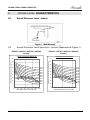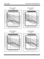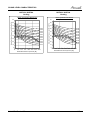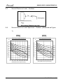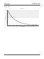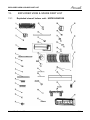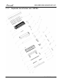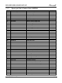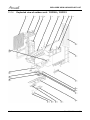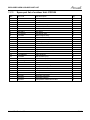
1
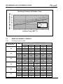
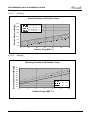
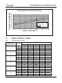
HGF / HHF Series
Indoor Units
AWSI-HGF009-H11
AWSI-HGF012-H11
AWSI-HGF018-H11
AWSI-HGF024-H11
Outdoor Units
AWSI-HHF009-H11
AWSI-HHF012-H11
AWSI-HHF018-H11
AWSI-HHF024-H11
AWAU-YGF009-H11
AWAU-YGF012-H11
AWAU-YGF018-H11
AWAU-YGF024-H11
REFRIGERANT
R410A
SM HGFHHF 1-A.1 GB
Version:2
HEAT PUMP
March- 2011
LIST OF EFFECTIVE PAGES
LIST OF EFFECTIVE PAGES
Note: Changes in the pages are indicated by a “Revision#” in the footer of each effected page
(when none indicates no changes in the relevant page). All pages in the following list represent
effected/ non effected pages divided by chapters.
Dates of issue for original and changed pages are:
Original ....... 01 ........ 27 Dec, 10
Updated...... 02 ........ 04 Mar, 11
Total number of pages in this publication is 75 consisting of the following:
Page
No.
Revision
No. #
Page
No.
Revision
No. #
Page
No.
Revision
No. #
Title........................... 1
A .............................. 1
i................................. 1
1-1 - 1-4…………….. 1
2-1 - 2-4…………….. 1
3-1…………………… 1
4-1 - 4-2…………….. 1
5-1 - 5-10……………. 1
6-1 - 6-4……………… 1
7-1 - 7-1……………… 1
8-1 - 8-4……………… 1
9-1……………………. 1
10-1………………….. 1
11-1 - 11-8…………... 1
12-1 - 12-2…………...1
13-1 - 13-18…………. 1
14-1………………….. 1
* Zero in this column indicates an original page.
A
SM HGFHHF 1-A.1 GB
TABLE OF CONTENTS
Table of Contents
1.
INTRODUCTION ............................................................................................................................. 1-1
2.
PRODUCT DATA SHEET............................................................................................................... 2-1
3.
RATING CONDITIONS ................................................................................................................... 3-1
4.
OUTLINE DIMENSION ................................................................................................................... 4-1
5.
PERFORMANCE DATA ................................................................................................................. 5-1
6.
SOUND LEVEL CHARACTERISTICS ........................................................................................... 6-1
7.
ELECTRICAL DATA....................................................................................................................... 7-1
8.
WIRING DIAGRAM......................................................................................................................... 8-1
9.
REFRIGERATION DIAGRAMS ...................................................................................................... 9-1
10.
TUBING CONNECTIONS ............................................................................................................... 10-1
11.
CONTROL SYSTEM ....................................................................................................................... 11-1
12.
TROUBLESHOOTING.................................................................................................................... 12-1
13.
EXPLODED VIEW & SPARE PART LIST...................................................................................... 13-1
14.
APPEDDIX ...................................................................................................................................... 14-1
SM HGFHHF 1-A.1 GB
i
INTRODUCTION
1.
INTRODUCTION
1.1
General
HGF/HHF//YGF series is monosplit fixed speed air conditioner designed for
residential buildings. The IDU HGF/HHF is a high-wall mounted type indoor with
modern appearance. Following models are included:
z
AWSI-HGF009-H11 / AWSI-HHF009-H11 // AWAU-YGF009-H11
z
AWSI-HGF012-H11 / AWSI-HHF012-H11 // AWAU-YGF012-H11
z
AWSI-HGF018-H11 / AWSI-HHF018-H11 // AWAU-YGF018-H11
z
AWSI-HGF024-H11 / AWSI-HHF024-H11 // AWAU-YGF024-H11
Different appearance styles are used in HGF and HHF indoors.
1.2
Main Features
The unit benefits from the most advanced technological innovations, namely:
• R410A models
• Microprocessor control and indoor LED display
• Energy efficiency class A in cooling mode for all models
• Max allowing tubing distance of 25m.(For model HGF/HHF018-024)
• Up to 10 m vertical high between indoor and outdoor units
• Cooling operation at outdoor temperature up to 46ºC.
• Easy installation and service.
• Sleep mode from remote control to save energy
• ON/OFF timer and clock display
• Vertical auto swing with motorized flap (any position stop)
• Intelligent Deicing
• Memory from power failure
• Rapid cooling/heating
• I-Feel function
• Cold air prevention in heating
• Clean function (Blow dry)
• Self diagnostic (Error indications) for ease of maintenance
SM HGFHHF 1-A.1 GB
1-1
INTRODUCTION
1.3
Indoor Unit
The indoor unit is wall mounted, and can be easily fitted to many types of residential
locations. It includes:
• LED display
• Variable speed with PG motor
• Motorized flap
• High efficiency filtration to ensure a best Air Quality : Advanced filtering combine
mechanical, Photo-catalytic + Bi-anti bacterial and observe bad gaseous and
smokes.
1.4
Control
The microprocessor indoor controller, and an infrared remote control, supplied as
standard, provide complete operating function and programming.
Remote control RC 8:
Compact and economically design, it offers excellent user comfort. Combining modern design
with high technology, the RC8 remote control offers powerful functions of real considering of user
comfort and energy saving of air-conditioner .
For detail of functions, please refer to Appendix 1
1-2
SM HGFHHF 1-A.1 GB
INTRODUCTION
1.5
Outdoor Unit
The outdoor units can be installed as floor or wall mounted units by using a wall
supporting bracket. The metal sheets are protected by anti- corrosion paint work
allowing long life resistance. All outdoor units are pre-charged. For further information
please refer to the Product Data Sheet, Chapter 2.
It includes :
• Compressor mounted in a soundproofed compartment :
• Axial fan.
• Outdoor coil with hydrophilic louver fins for RC units.
• Outlet air fan grill.
• Interconnecting wiring terminal block.
1.6
Tubing Connections
Flare type interconnecting tubing to be produced on site.
For further details please refer to the Installation Manual.
1.7
Inbox Documentation
Each unit is supplied with its own installation, operation and remote control manuals.
SM HGFHHF 1-A.1 GB
1-3
INTRODUCTION
1.8
Matching Table
INDOOR UNITS
OUTDOOR
UNITS
AWSI-HGF009-H11
AWSI-HGF012-H11
AWSI-HGF018-H11
AWSI-HGF024-H11
AWSI-HHF009-H11
AWSI-HHF012-H11
AWSI-HHF018-H11
AWSI-HHF024-H11
√
AWAU-YGF009-H11
√
AWAU-YGF012-H11
√
AWAU-YGF018-H11
√
AWAU-YGF022-H11
1-4
SM HGFHHF 1-A.1 GB
PRODUCT DATASHEET
2.
PRODUCT DATA SHEET
HGF009 / HHF009 // YGF009
2.1
Model Indoor Unit
Model Outdoor Unit
Installation Method of Pipe
Characteristics
Capacity (4)
Power input (4)
EER (Cooling) or COP(Heating) (4)
Energy efficiency class
Units
kW
kW
W/W
V
Ph
Hz
A
Power supply
Rated current
Power factor
Prated (IDU+ODU)
Circuit breaker rating
Fan type & quantity
Fan speeds
W
A
Cooling
Heating
SH/H/M/L
SH/H/M/L
SH/H/M/L
Min
SH/H/M/L
SH/H/M/L
OUTDOOR
INDOOR
Air flow (1)
External static pressure
Sound power level (2)
Sound pressure level(3)
Moisture removal
Condensate drain tube I.D
Dimensions
WxHxD
Net Weight
Package dimensions
WxHxD
Packaged weight
Refrigerant control
Compressor type, model
Fan type & quantity
Fan speeds
H
Air flow
H
Sound power level
H
Sound pressure level(3)
H
Dimensions
WxHxD
Net Weight
Package dimensions
WxHxD
Packaged weight
Refrigerant type
Standard charge
Additional charge
Liquid line
Connections
Suction line
between units
Max.tubing length
Max.height difference
Operation control type
RPM
RPM
M3/hr
Pa
dB(A)
dB(A)
l/hr
mm
mm
kg
mm
kg
RPM
M3/hr
dB(A)
dB(A)
mm
kg
mm
kg
kg(4m)
g/m
In.(mm)
In.(mm)
m.
m.
HGF009/HHF009
YGF009
Flared
Cooling
Heating
2.64
2.81
0.82
0.78
3.21
3.61
A
A
220-240
1
50
3.8
3.6
0.92
0.92
1120
10A
Crossflow x 1
1390/1280/1180/1080
1350/1250/1140/1040
400/370/340/310
0
50/47/45/42
40/37/35/32
1.0
16
730x255x174
8
790x325x245
10.5
Capillary
Rotary, Panasonic-5PS102EAA22
Propeller(direct) x 1
830
1500
60
50
785x540x320
31
820x580x355
34
R410A
0.76
30g/m(4m<L<15m)
1/4"(6.35)
3/8"(9.53)
Max. 15
Max. 10
Remote control
(1)Airflow in ducted units; at nominal external static pressure.
(2)Sound power in ducted units is measured at air discharge.
(3)Sound pressure level measured at 1-meter distance from unit.
(4)Rating conditions in accordance to ISO 5151 and ISO 13253 (for ducted units).
SM HGFHHF 1-A.1 GB
2-1
PRODUCT DATASHEET
2.2
HGF012 / HHF012 // YGF012
Model Indoor Unit
Model Outdoor Unit
Installation Method of Pipe
Characteristics
Capacity (4)
Power input (4)
EER (Cooling) or COP(Heating) (4)
Energy efficiency class
Units
kW
kW
W/W
V
Ph
Hz
A
Power supply
Rated current
Power factor
Prated (IDU+ODU)
Circuit breaker rating
Fan type & quantity
Fan speeds
W
A
Cooling
Heating
SH/H/M/L
SH/H/M/L
SH/H/M/L
Min
SH/H/M/L
SH/H/M/L
OUTDOOR
INDOOR
Air flow (1)
External static pressure
Sound power level (2)
Sound pressure level(3)
Moisture removal
Condensate drain tube I.D
Dimensions
WxHxD
Net Weight
Package dimensions
WxHxD
Packaged weight
Refrigerant control
Compressor type, model
Fan type & quantity
Fan speeds
H
Air flow
H
Sound power level
H
Sound pressure level(3)
H
Dimensions
WxHxD
Net Weight
Package dimensions
WxHxD
Packaged weight
Refrigerant type
Standard charge
Additional charge
Liquid line
Connections
Suction line
between units
Max.tubing length
Max.height difference
Operation control type
RPM
RPM
m3/hr
Pa
dB(A)
dB(A)
l/hr
mm
mm
kg
mm
kg
RPM
m3/hr
dB(A)
dB(A)
mm
kg
mm
kg
kg(4m)
g/m
In.(mm)
In.(mm)
m.
m.
HGF012/HHF012
YGF012
Flared
Cooling
Heating
3.22
3.52
1.00
0.97
3.21
3.61
A
A
220-240
1
50
4.7
4.6
0.92
0.92
1450
16A
Crossflow x 1
1350/1250/1100/950
1350/1250/1100/950
550/500/420/350
0
50/48/45/42
40/38/35/32
1.0
16
790x265x177
9
870x355x248
12
Capillary
Rotary, LANDA- QXA-B120C150
Propeller(direct) x 1
850
1800
62
52
798x540x320
35
825x580x355
40
R410A
0.76
30g/m(4m<L<20m)
1/4"(6.35)
1/2"(12.7)
Max. 20
Max. 10
Remote control
(1)Airflow in ducted units; at nominal external static pressure.
(2)Sound power in ducted units is measured at air discharge.
(3)Sound pressure level measured at 1-meter distance from unit.
(4)Rating conditions in accordance to ISO 5151 and ISO 13253 (for ducted units).
2-2
SM HGFHHF 1-A.1 GB
PRODUCT DATASHEET
2.3
HGF018 / HHF018 // YGF018
Model Indoor Unit
Model Outdoor Unit
Installation Method of Pipe
Characteristics
Capacity (4)
Power input (4)
EER (Cooling) or COP(Heating) (4)
Energy efficiency class
Units
kW
kW
W/W
V
Ph
Hz
A
Power supply
Rated current
Power factor
Prated (IDU+ODU)
Circuit breaker rating
Fan type & quantity
Fan speeds
W
A
Cooling
Heating
SH/H/M/L
SH/H/M/L
SH/H/M/L
Min
SH/H/M/L
SH/H/M/L
OUTDOOR
INDOOR
Air flow (1)
External static pressure
Sound power level (2)
Sound pressure level(3)
Moisture removal
Condensate drain tube I.D
Dimensions
WxHxD
Net Weight
Package dimensions
WxHxD
Packaged weight
Refrigerant control
Compressor type, model
Fan type & quantity
Fan speeds
H
Air flow
H
Sound power level
H
Sound pressure level(3)
H
Dimensions
WxHxD
Net Weight
Package dimensions
WxHxD
Packaged weight
Refrigerant type
Standard charge
Additional charge
Liquid line
Connections
Suction line
between units
Max.tubing length
Max.height difference
Operation control type
RPM
RPM
m3/hr
Pa
dB(A)
dB(A)
l/hr
mm
mm
kg
mm
kg
RPM
m3/hr
dB(A)
dB(A)
mm
kg
mm
kg
kg(4m)
g/m
In.(mm)
In.(mm)
m.
m.
HGF018/HHF018
YGF018
Flared
Cooling
Heating
5.30
5.70
1.64
1.67
3.23
3.41
A
B
220-240
1
50
7.8
7.9
0.92
0.92
2550
25A
Crossflow x 1
1350/1200/1050/900
1350/1200/1050/900
850/780/650/550
0
58/55/52/48
48/45/42/38
3.0
16
940x298x200
13
1010x380x285
17
Capillary
Rotary, HITACHI - ASH210SV-C8LU
Propeller(direct) x 1
860
2790
64
54
913x680x378
46
994x725x428
50
R410A
1.5
30g/m(4m<L<25m)
1/4"(6.35)
1/2"(12.7)
Max. 25
Max. 10
Remote control
(1)Airflow in ducted units; at nominal external static pressure.
(2)Sound power in ducted units is measured at air discharge.
(3)Sound pressure level measured at 1-meter distance from unit.
(4)Rating conditions in accordance to ISO 5151 and ISO 13253 (for ducted units).
SM HGFHHF 1-A.1 GB
2-3
PRODUCT DATASHEET
2.4
HGF024/ HHF024 // YGF024
Model Indoor Unit
Model Outdoor Unit
Installation Method of Pipe
Characteristics
Capacity (4)
Power input (4)
EER (Cooling) or COP(Heating) (4)
Energy efficiency class
Units
kW
kW
W/W
V
Ph
Hz
A
Power supply
Rated current
Power factor
Prated (IDU+ODU)
Circuit breaker rating
Fan type & quantity
Fan speeds
W
A
Cooling
Heating
SH/H/M/L
SH/H/M/L
SH/H/M/L
Min
SH/H/M/L
SH/H/M/L
OUTDOOR
INDOOR
Air flow (1)
External static pressure
Sound power level (2)
Sound pressure level(3)
Moisture removal
Condensate drain tube I.D
Dimensions
WxHxD
Net Weight
Package dimensions
WxHxD
Packaged weight
Refrigerant control
Compressor type, model
Fan type & quantity
Fan speeds
H
Air flow
H
Sound power level
H
Sound pressure level(3)
H
Dimensions
WxHxD
Net Weight
Package dimensions
WxHxD
Packaged weight
Refrigerant type
Standard charge
Additional charge
Liquid line
Connections
Suction line
between units
Max.tubing length
Max.height difference
Operation control type
RPM
RPM
m3/hr
Pa
dB(A)
dB(A)
l/hr
mm
mm
kg
mm
kg
RPM
m3/hr
dB(A)
dB(A)
mm
kg
mm
kg
kg(4m)
g/m
In.(mm)
In.(mm)
m.
m.
HGF024/HHF024
YGF024
Flared
Cooling
Heating
6.16
6.50
1.90
1.90
3.24
3.42
A
B
220-240
1
50
8.9
8.9
0.92
0.92
2700
25A
Crossflow x 1
1350/1200/1050/900
1350/1200/1050/900
850/780/650/550
0
57/54/51/48
47/44/41/38
3.0
16
940x298x200
13
1010x380x285
17
Capillary
Rotary, HITACHI - ASH232SV-C8LU
Propeller(direct) x 1
780
2790
64
54
913x680x378
46
994x725x428
50
R410A
1.45
30g/m(4m<L<15m)
1/4"(6.35)
1/2"(12.7)
Max. 25
Max. 10
Remote control
(1)Airflow in ducted units; at nominal external static pressure.
(2)Sound power in ducted units is measured at air discharge.
(3)Sound pressure level measured at 1-meter distance from unit.
(4)Rating conditions in accordance to ISO 5151 and ISO 13253 (for ducted units).
2-4
SM HGFHHF 1-A.1 GB
RATING CONDITIONS
3.
RATING
TING CONDITIONS
Rating conditions in accordance with ISO 5151 and ISO 13253 (for ducted units).
Cooling:
Indoor:
27oC DB 19oC WB
Outdoor: 35 oC DB
Heating:
Indoor:
20oC DB
Outdoor: 7oC DB 6oC WB
3.1
Operating Limits
R410A
Upper limit
Lower limit
Upper limit
Heating
Lower limit
Cooling
Voltage
SM HGFHHF 1-A.1 GB
Indoor
32 C DB 23oC WB
21oC DB 15oC WB
27oC DB
10oC DB
o
Outdoor
46 C DB
21oC DB
24oC DB 18oC WB
-9oC DB 80%RH
o
1-PH 50Hz 198 – 264 V
3-1
OUTLINE DIMENSION
OUTLINE
NE DIMENSION
4.
4.1
Indoor: HGF/HHF009-012-018-024
Unit: mm
Model
09K
12K
18-24K
W
730
790
940
SM HGFHHF 1-A.1 GB
H
255
265
298
D
174
177
200
Q
27
35
52
R
562
605
694
S
141
150
194
4-1
OUTLINE DIMENSION
4.2
Outdoor: YGF009-012-018-024
Model 09/12
Model 18/24
4-2
SM HGFHHF 1-A.1 GB
OUTLINE DIMENSION
Unit: mm
Model
09-12K
18-24K
W
776
913
SM HGFHHF 1-A.1 GB
H
549
680
D
320
378
W1
714
847
W2
510
549
D1
286
342
4-3
PERFORMANCE DATA & PRESSURE CURVES
5.
PERFORMANCE
RFORMANCE DATA
5.1
HGF009 / HHF009 // YGF009
5.1.1
Cooling Capacity (kW)
Entering Air DB
OD Coil(oC)
Data
20
25
30
35
40
46
Entering Air WB/DB ID Coil(oC)
15/21
17/24
19/27
21/29
23/32
TC
SC
2.69
1.77
2.84
1.87
2.92
1.95
2.99
2.00
3.06
2.04
PI
0.63
0.63
0.64
0.64
0.64
TC
SC
2.55
1.73
2.75
1.83
2.89
1.93
2.98
1.99
3.05
2.02
PI
0.68
0.69
0.69
0.70
0.70
TC
SC
2.38
1.67
2.59
1.78
2.80
1.89
2.90
1.95
2.99
1.98
PI
0.74
0.75
0.75
0.76
0.77
TC
2.20
2.39
2.64
2.77
2.90
SC
1.59
1.70
1.85
1.90
1.94
PI
0.79
0.81
0.82
0.83
0.83
TC
SC
2.00
1.50
2.18
1.61
2.38
1.75
2.60
1.80
2.74
1.84
PI
0.86
0.87
0.89
0.90
0.90
TC
SC
1.74
1.38
1.90
1.48
2.09
1.59
2.31
1.65
2.49
1.69
PI
0.94
0.95
0.97
0.99
1.00
LEGEND
TC
SC
PI
WB
DB
ID
OU
–
–
–
–
–
–
–
Total Cooling Capacity, kW
Sensible Capacity, kW
Power Input, kW
Wet Bulb Temp., (oC)
Dry Bulb Temp., (oC)
Indoor
Outdoor
SM HGFHHF 1-A.1 GB
5-1
PERFORMANCE DATA & PRESSURE CURVES
5.1.3
Heating Capacity (kW)
ENTERING AIR DB ID COIL(OC)
15
20
25
ENTERING WB
OD COIL(oC)
TH
Pl
TH
Pl
TH
Pl
-10
1.48
0.62
1.42
0.66
1.36
0.70
-7
1.59
0.64
1.53
0.67
1.48
0.71
-2
1.69
0.65
1.63
0.69
1.58
0.72
2
2.05
0.68
1.97
0.72
1.89
0.76
6
2.90
0.73
2.81
0.78
2.72
0.83
10
3.15
0.77
3.07
0.82
2.98
0.88
15
3.40
0.80
3.32
0.86
3.24
0.92
20
3.59
0.83
3.50
0.90
3.40
0.97
LEGEND
TH
PI
WB
DB
ID
OU
5.1.4
5.1.4.1
–
–
–
–
–
–
Total Heating Capacity, kW
Power Input, kW
Wet Bulb Temp., (oC)
Dry Bulb Temp., (oC)
Indoor
Outdoor
Curves
Cooling
Suction Pressure (Bar[g])
Suction Pressure VS.Outdoor Temp
12.0
15/21(WB/DB
17/24(WB/DB
19/27(WB/DB
21/29(WB/DB
23/32(WB/DB
11.0
10.0
9.0
ºC)
ºC)
ºC)
ºC)
ºC)
8.0
7.0
6.0
5.0
15
20
25
30
35
40
46
o
Outdoor Temp.(DB C )
5-2
SM HGFHHF 1-A.1 GB
PERFORMANCE DATA & PRESSURE CURVES
5.1.4.2
Heating
Discharge Pressure(Bar[g])
Discharge Pressure VS.Outdoor Temp
38
36
34
32
30
28
26
24
22
20
18
16
25 DB (ºC)
20 DB (ºC)
15 DB (ºC)
-10
-5
0
5
o
10
15
20
Outdoor Temp.( WB C )
5.2
HGF012 / HHF012 // YGF012
5.2.1
Cooling Capacity (kW)
Entering Air DB
OD Coil(oC)
Data
20
25
30
35
40
46
SM HGFHHF 1-A.1 GB
Entering Air WB/DB ID Coil(oC)
15/21
17/24
19/27
21/29
23/32
TC
3.29
3.46
3.57
3.66
3.74
SC
2.17
2.28
2.38
2.45
2.49
PI
0.77
0.78
0.78
0.78
0.78
TC
3.11
3.36
3.53
3.64
3.73
SC
2.11
2.24
2.36
2.43
2.47
PI
0.84
0.84
0.85
0.85
0.86
TC
2.91
3.17
3.42
3.54
3.65
SC
2.04
2.17
2.31
2.38
2.42
PI
0.90
0.91
0.92
0.93
0.94
TC
2.69
2.92
3.22
3.38
3.54
SC
1.94
2.08
2.26
2.32
2.37
PI
0.97
0.99
1.00
1.01
1.02
TC
2.45
2.67
2.91
3.18
3.34
SC
1.83
1.97
2.13
2.20
2.25
PI
1.05
1.06
1.08
1.10
1.11
TC
2.12
2.32
2.55
2.82
3.04
SC
1.69
1.81
1.95
2.01
2.06
PI
1.15
1.16
1.19
1.21
1.22
5-3
PERFORMANCE DATA & PRESSURE CURVES
LEGEND
TC
SC
PI
WB
DB
ID
OU
5.2.2
–
–
–
–
–
–
–
Total Cooling Capacity, kW
Sensible Capacity, kW
Power Input, kW
Wet Bulb Temp., (oC)
Dry Bulb Temp., (oC)
Indoor
Outdoor
Heating Capacity (kW)
ENTERING AIR DB ID COIL(OC)
15
20
25
ENTERING WB
OD COIL(oC)
TH
Pl
TH
Pl
TH
Pl
-10
1.85
0.78
1.78
0.83
1.71
0.87
-7
1.99
0.80
1.92
0.84
1.85
0.89
-2
2.11
0.81
2.04
0.86
1.97
0.90
2
2.57
0.85
2.46
0.90
2.36
0.95
6
3.62
0.91
3.52
0.97
3.39
1.03
10
3.94
0.96
3.83
1.03
3.73
1.10
15
4.25
1.00
4.15
1.08
4.04
1.15
20
4.48
1.03
4.38
1.12
4.25
1.21
LEGEND
TH
PI
WB
DB
ID
OU
5-4
–
–
–
–
–
–
Total Heating Capacity, kW
Power Input, kW
Wet Bulb Temp., (oC)
Dry Bulb Temp., (oC)
Indoor
Outdoor
SM HGFHHF 1-A.1 GB
PERFORMANCE DATA & PRESSURE CURVES
5.1.5
5.1.5.1
Curves
Cooling
Suction Pressure VS.Outdoor Temp
Suction Pressure (Bar[g])
14.0
15/21(WB/DB
17/24(WB/DB
19/27(WB/DB
21/29(WB/DB
23/32(WB/DB
13.0
12.0
ºC)
ºC)
ºC)
ºC)
ºC)
11.0
10.0
9.0
8.0
7.0
15
20
25
30
35
40
46
o
Outdoor Temp.(DB C )
5.1.5.2
Heating
Discharge Pressure(Bar[g])
Discharge Pressure VS.Outdoor Temp
36
34
32
30
28
26
24
22
20
18
16
25 DB (ºC)
20 DB (ºC)
15 DB (ºC)
-10
-5
0
5
o
10
15
20
Outdoor Temp.( WB C )
SM HGFHHF 1-A.1 GB
5-5
PERFORMANCE DATA & PRESSURE CURVES
5.3
HGF018 / HHF018 // YGF018
5.3.1
Cooling Capacity (kW)
Entering Air
DB OD Coil(oC)
Data
TC
SC
PI
TC
SC
PI
TC
SC
PI
TC
SC
PI
TC
SC
PI
TC
SC
PI
20
25
30
35
40
46
Entering Air WB/DB ID Coil(oC)
15/21
5.40
3.56
1.26
5.11
3.47
1.36
4.78
3.36
1.47
4.43
3.20
1.59
4.03
3.01
1.71
3.49
2.77
1.87
17/24
5.70
3.75
1.27
5.52
3.68
1.37
5.21
3.57
1.49
4.80
3.43
1.61
4.38
3.24
1.74
3.82
2.97
1.90
19/27
5.88
3.91
1.27
5.81
3.88
1.38
5.63
3.80
1.51
5.30
3.71
1.64
4.78
3.51
1.77
4.20
3.20
1.94
21/29
6.02
4.02
1.28
5.98
3.99
1.39
5.83
3.91
1.52
5.57
3.82
1.65
5.23
3.62
1.79
4.64
3.31
1.97
23/32
6.14
4.10
1.28
6.13
4.07
1.40
6.00
3.98
1.53
5.83
3.89
1.66
5.50
3.70
1.81
5.00
3.39
1.99
LEGEND
TC
SC
PI
WB
DB
ID
OU
5-6
–
–
–
–
–
–
–
Total Cooling Capacity, kW
Sensible Capacity, kW
Power Input, kW
Wet Bulb Temp., (oC)
Dry Bulb Temp., (oC)
Indoor
Outdoor
SM HGFHHF 1-A.1 GB
PERFORMANCE DATA & PRESSURE CURVES
5.1.3
Heating Capacity (kW)
ENTERING AIR DB ID COIL(OC)
15
20
25
ENTERING WB
OD COIL(oC)
TH
Pl
TH
Pl
TH
Pl
-10
2.99
1.34
2.88
1.42
2.76
1.49
-7
3.22
1.37
3.11
1.44
2.99
1.52
-2
3.42
1.39
3.31
1.47
3.19
1.55
2
4.16
1.45
3.99
1.54
3.82
1.64
6
5.87
1.56
5.70
1.67
5.50
1.77
10
6.38
1.65
6.21
1.76
6.04
1.88
15
6.90
1.72
6.73
1.85
6.56
1.97
20
7.27
1.77
7.10
1.92
6.90
2.07
LEGEND
TH
PI
WB
DB
ID
OU
5.1.6
5.1.6.1
–
–
–
–
–
–
Total Heating Capacity, kW
Power Input, kW
Wet Bulb Temp., (oC)
Dry Bulb Temp., (oC)
Indoor
Outdoor
Curves
Cooling
Suction Pressure VS.Outdoor Temp
Suction Pressure (Bar[g])
14.0
15/21(WB/DB
17/24(WB/DB
19/27(WB/DB
21/29(WB/DB
23/32(WB/DB
13.0
12.0
ºC)
ºC)
ºC)
ºC)
ºC)
11.0
10.0
9.0
8.0
7.0
6.0
15
20
25
30
35
40
46
o
Outdoor Temp.(DB C )
SM HGFHHF 1-A.1 GB
5-7
PERFORMANCE DATA & PRESSURE CURVES
5.1.6.2
Heating
Discharge Pressure(Bar[g])
Discharge Pressure VS.Outdoor Temp
40
38
36
34
32
30
28
26
24
22
20
18
16
25 DB (ºC)
20 DB (ºC)
15 DB (ºC)
-10
-5
0
5
o
10
15
20
Outdoor Temp.( WB C )
5.4
HGF024 / HHF024 // YGF024
5.4.1
Cooling Capacity (kW)
Entering Air
DB OD Coil(oC)
20
25
30
35
40
46
5-8
Data
TC
SC
PI
TC
SC
PI
TC
SC
PI
TC
SC
PI
TC
SC
PI
TC
SC
PI
Entering Air WB/DB ID Coil(oC)
15/21
6.28
4.14
1.46
5.94
4.03
1.58
5.55
3.90
1.70
5.14
3.71
1.84
4.68
3.50
1.98
4.06
3.22
2.17
17/24
6.62
4.36
1.47
6.41
4.28
1.59
6.05
4.15
1.73
5.58
3.98
1.87
5.09
3.76
2.01
4.44
3.45
2.20
19/27
6.82
4.54
1.47
6.74
4.51
1.60
6.53
4.41
1.74
6.16
4.31
1.90
5.55
4.08
2.05
4.88
3.72
2.25
21/29
6.99
4.67
1.48
6.95
4.64
1.61
6.77
4.54
1.76
6.46
4.43
1.91
6.07
4.21
2.07
5.39
3.85
2.28
23/32
7.14
4.76
1.48
7.11
4.72
1.62
6.97
4.63
1.77
6.77
4.52
1.93
6.39
4.29
2.09
5.81
3.93
2.31
SM HGFHHF 1-A.1 GB
PERFORMANCE DATA & PRESSURE CURVES
LEGEND
TC
SC
PI
WB
DB
ID
OU
5.4.2
–
–
–
–
–
–
–
Total Cooling Capacity, kW
Sensible Capacity, kW
Power Input, kW
Wet Bulb Temp., (oC)
Dry Bulb Temp., (oC)
Indoor
Outdoor
Heating Capacity (kW)
ENTERING AIR DB ID COIL(OC)
15
20
25
ENTERING WB
OD COIL(oC)
TH
Pl
TH
Pl
TH
Pl
-10
3.41
1.52
3.28
1.62
3.15
1.70
-7
3.67
1.56
3.54
1.64
3.41
1.73
-2
3.90
1.58
3.77
1.67
3.64
1.77
2
4.75
1.65
4.55
1.76
4.36
1.86
6
6.70
1.78
6.50
1.90
6.27
2.02
10
7.28
1.88
7.09
2.00
6.89
2.14
15
7.87
1.96
7.67
2.11
7.48
2.24
20
8.29
2.01
8.09
2.19
7.87
2.36
LEGEND
TH
PI
WB
DB
ID
OU
–
–
–
–
–
–
Total Heating Capacity, kW
Power Input, kW
Wet Bulb Temp., (oC)
Dry Bulb Temp., (oC)
Indoor
Outdoor
SM HGFHHF 1-A.1 GB
5-9
PERFORMANCE DATA & PRESSURE CURVES
5.1.7
5.1.7.1
Curves
Cooling
Suction Pressure VS.Outdoor Temp
Suction Pressure (Bar[g])
14.0
15/21(WB/DB
17/24(WB/DB
19/27(WB/DB
21/29(WB/DB
23/32(WB/DB
13.0
12.0
ºC)
ºC)
ºC)
ºC)
ºC)
11.0
10.0
9.0
8.0
7.0
6.0
15
20
25
30
35
40
46
o
Outdoor Temp.(DB C )
5.1.7.2
Heating
Discharge Pressure(Bar[g])
Discharge Pressure VS.Outdoor Temp
40
38
36
34
32
30
28
26
24
22
20
18
16
25 DB (ºC)
20 DB (ºC)
15 DB (ºC)
-10
-5
0
5
o
10
15
20
Outdoor Temp.( WB C )
5-10
SM HGFHHF 1-A.1 GB
SOUND LEVEL CHARACTERISTICS
6.
SOUND LEVEL CHARACTERISTICS
6.1
Sound Pressure Level - Indoor
6.2
Sound Pressure Level Spectrum - Indoor (Measured as Figure 1)
HGF007 / HHF007 / HGF009 / HHF009
Cooling
HGF007 / HHF007 / HGF009 / HHF009
Heating
Noise spectrum & NC Curves
Noise spectrum & NC Curves
90
Octave Band Sound Pressure Level [dB re 20 mPa]
80
70
NC65
60
NC60
NC55
50
NC50
NC45
40
NC40
NC35
30
NC30
NC25
20
NC20
NC15
10
Octave Band Sound Pressure Level [dB re 20 mPa]
90
80
70
NC65
NC60
NC55
NC50
NC45
NC40
NC35
NC30
60
50
40
30
NC25
NC20
NC15
20
10
0
0
63
125
250
500
1000
2000
4000
Octave Band Center Frequencies [Hz]
SM HGFHHF 1-A.1 GB
8000
63
125
250
500 1000 2000 4000 8000
Octave Band Center Frequencies [Hz]
6-1
SOUND LEVEL CHARACTERISTICS
HGF012 / HHF012
Cooling
HGF012 / HHF012
Heating
Noise spectrum & NC Curves
Noise spectrum & NC Curves
90
Octave Band Sound Pressure Level [dB re 20 mPa]
80
70
NC65
60
NC60
NC55
50
NC50
NC45
40
NC40
NC35
30
NC30
NC25
20
NC20
NC15
10
Octave Band Sound Pressure Level [dB re 20 mPa]
90
80
70
NC65
NC60
NC55
NC50
NC45
NC40
NC35
NC30
60
50
40
30
NC25
NC20
NC15
20
10
0
0
63
125
250
500
1000
2000
4000
63
8000
Octave Band Center Frequencies [Hz]
HGF018 / HHF018
Cooling
80
80
70
NC65
NC60
NC55
NC50
NC45
NC40
NC35
NC30
30
NC25
NC20
NC15
20
10
70
NC65
NC60
NC55
NC50
NC45
NC40
NC35
NC30
60
50
40
30
NC25
NC20
NC15
20
10
0
0
63
125
250
500
1000 2000 4000 8000
Octave Band Center Frequencies [Hz]
6-2
Octave Band Sound Pressure Level [dB re 20 mPa]
Octave Band Sound Pressure Level [dB re 20 mPa]
90
40
500 1000 2000 4000 8000
Noise spectrum & NC Curves
90
50
250
HGF018 / HHF018
Heating
Noise spectrum & NC Curves
60
125
Octave Band Center Frequencies [Hz]
63
125
250
500 1000 2000 4000 8000
Octave Band Center Frequencies [Hz]
SM HGFHHF 1-A.1 GB
SOUND LEVEL CHARACTERISTICS
HGF024 / HHF024
Cooling
HGF024 / HHF024
Heating
Noise spectrum & NC Curves
90
80
80
70
NC65
NC60
NC55
NC50
NC45
NC40
NC35
NC30
60
50
40
30
NC25
NC20
NC15
20
10
Octave Band Sound Pressure Level [dB re 20 mPa]
Octave Band Sound Pressure Level [dB re 20 mPa]
Noise spectrum & NC Curves
90
70
NC65
NC60
NC55
NC50
NC45
NC40
NC35
NC30
60
50
40
30
NC25
NC20
NC15
20
10
0
0
63
125
250
500
1000 2000 4000 8000
Octave Band Center Frequencies [Hz]
SM HGFHHF 1-A.1 GB
63
125
250
500 1000 2000 4000 8000
Octave Band Center Frequencies [Hz]
6-3
SOUND LEVEL CHARACTERISTICS
6.3
Sound Pressure Level - Outdoor
6.4
Sound Pressure Level Spectrum - Outdoor (Measured as Figure
1)
YGF007
Cooling
YGF007
Heating
Noise spectrum & NC Curves
90
90
80
80
70
NC65
NC60
NC55
NC50
NC45
NC40
NC35
NC30
60
50
40
30
NC25
NC20
NC15
20
10
0
70
NC65
60
NC60
NC55
50
NC50
NC45
40
NC40
NC35
30
NC30
NC25
20
NC20
NC15
10
0
63
125
250
500 1000 2000 4000 8000
Octave Band Center Frequencies [Hz]
6-4
Octave Band Sound Pressure Level [dB re 20 mPa]
Octave Band Sound Pressure Level [dB re 20 mPa]
Noise spectrum & NC Curves
63
125
250
500
1000 2000 4000 8000
Octave Band Center Frequencies [Hz]
SM HGFHHF 1-A.1 GB
SOUND LEVEL CHARACTERISTICS
YGF009
Cooling
YGF009
Heating
Noise spectrum & NC Curves
90
90
80
80
70
NC65
NC60
NC55
NC50
NC45
NC40
NC35
NC30
60
50
40
30
NC25
NC20
NC15
20
10
Octave Band Sound Pressure Level [dB re 20 mPa]
Octave Band Sound Pressure Level [dB re 20 mPa]
Noise spectrum & NC Curves
70
NC65
NC60
NC55
NC50
NC45
NC40
NC35
NC30
60
50
40
30
NC25
NC20
NC15
20
10
0
0
63
125
250
63
500 1000 2000 4000 8000
125
250
Octave Band Center Frequencies [Hz]
Octave Band Center Frequencies [Hz]
YGF012
Cooling
YGF012
Heating
Noise spectrum & NC Curves
90
90
80
80
70
NC65
NC60
NC55
NC50
NC45
NC40
NC35
NC30
50
40
30
NC25
NC20
NC15
20
10
Octave Band Sound Pressure Level [dB re 20 mPa]
Octave Band Sound Pressure Level [dB re 20 mPa]
Noise spectrum & NC Curves
60
500 1000 2000 4000 8000
70
NC65
NC60
NC55
NC50
NC45
NC40
NC35
NC30
60
50
40
30
NC25
NC20
NC15
20
10
0
0
63
125
250
500
1000 2000 4000 8000
Octave Band Center Frequencies [Hz]
SM HGFHHF 1-A.1 GB
63
125
250
500 1000 2000 4000 8000
Octave Band Center Frequencies [Hz]
6-5
SOUND LEVEL CHARACTERISTICS
YGF018
Cooling
YGF018
Heating
Noise spectrum & NC Curves
90
80
80
70
NC65
NC60
NC55
NC50
NC45
NC40
NC35
NC30
60
50
40
30
NC25
NC20
NC15
20
10
Octave Band Sound Pressure Level [dB re 20 mPa]
Octave Band Sound Pressure Level [dB re 20 mPa]
Noise spectrum & NC Curves
90
70
NC65
NC60
NC55
NC50
NC45
NC40
NC35
NC30
60
50
40
30
NC25
NC20
NC15
20
10
0
0
63
125
250
500
63
1000 2000 4000 8000
125
YGF024
Cooling
YGF024
Heating
Noise spectrum & NC Curves
90
90
80
80
70
NC65
NC60
NC55
NC50
NC45
NC40
NC35
NC30
60
50
40
30
NC25
NC20
NC15
20
10
0
Octave Band Sound Pressure Level [dB re 20 mPa]
Octave Band Sound Pressure Level [dB re 20 mPa]
500 1000 2000 4000 8000
Octave Band Center Frequencies [Hz]
Noise spectrum & NC Curves
70
NC65
NC60
60
NC55
50
NC50
NC45
NC40
40
NC35
30
NC30
20
NC25
NC20
10
NC15
0
63
125
250
500 1000 2000 4000 8000
Octave Band Center Frequencies [Hz]
6-6
250
Octave Band Center Frequencies [Hz]
63
125
250
500
1000
2000
4000
8000
Octave Band Center Frequencies [Hz]
SM HGFHHF 1-A.1 GB
ELECTRICAL DATA
7.
ELECTRICAL DATA
MODEL
YGF009
YGF012
YGF018
YGF024
To indoor
Power Supply
Max Current, A
5.1A
1PH-220-240V-50Hz
6.3A
11.1A
Circuit Breaker, A
10A
16A
11.7
25A
25A
Power Supply
No. X Cross Section mm2
3x1.0
3x2.5
Interconnecting Cable
No. X Cross Section mm2
3X1.0+2X0.75
5x2.5
NOTE
Power wiring cord should comply with local laws and electrical regulations requirements.
SM HGFHHF 1-A.1 GB
7-1
WIRING DIAGRAM
8.
8.1
WIRING DIAGRAM
HGF009 / HHF009 // YGF009
SM HGFHHF 1-A.1 GB
8-1
WIRING DIAGRAM
8.2
8-2
HGF012 / HGF012 // YGF012
SM HGFHHF 1-A.1 GB
WIRING DIAGRAM
8.3
HGF018 / HHF018 // YGF018
SM HGFHHF 1-A.1 GB
8-3
WIRING DIAGRAM
8.4
8-4
HGF024 / HHF024 // YGF024
SM HGFHHF 1-A.1 GB
REFRIGERATION DIAGRAMS
9.
REFRIGERATION DIAGRAMS
SM HGFHHF 1-A.1 GB
9-1
TUBING CONNECTIONS
10.
TUBING CONNECTIONS
When the outdoor unit is installed above the indoor unit an oil trap is required every 5m along the
suction line at the lowest point of the riser. In case the indoor unit is installed above the outdoor, no
trap is required.
SM HGFHHF 1-A.1 GB
10-1
CONTROL SYSTEM
11.
CONTROL SYSTEM
11.1
Electronic Control
11.1.1
Abbreviations
AC
A/C
ANY
COMP
CPU
E2PROM, EEP
H/W
ICT
IF, IFAN
IR
Max
Min
min
NA
OCT
OF, OFAN
RAT
RC
R/C
RCT
RH
RV
SB, STBY
Sec
Sect
SH
SPT
ST
S/W
TEMP
W/O
SM HGFHHF 1-A.1 GB
-Alternate Current
- Air-Conditioner
- ON or OFF status
- Compressor
- Central Processing Unit
- Erase Enable Programmable Read Only Memory
- Hardware
- Indoor Coil Temperature sensor
- Indoor Fan
- Infra Red
- Maximum
- Minimum
- Minute (time)
- Not Applicable
- Outdoor Coil Temperature sensor
- Outdoor Fan OPER - Operate Para. - Paragraph
- Return Air Temperature (RT1) sensor
- Reverse Cycle (Heat Pump)
- Remote Control
- Remote Control Temperature
- Resistance Heater
- Reversing Valve
- Stand-By
- Second (time)
- Section
- Supplementary Heater
- Set Point Temperature
- Standard (a Model with Cooling Only)
- Software
- Temperature
- Without
11-1
CONTROL SYSTEM
11.1.2
System Operation Concept
11.1.3
Compressor operation
For each Mode including POWER OFF & SB, a Min time delay of 3 min before COMP restarting
except during outdoor deicing.
Whenever COMP starts, it will not stop in 6 min even the RAT is changed.
* For the units with memory function, the 1st time of Power ON, there will be no 3 min delay if the
previous stage of unit is OFF.
11.1.4
Indoor Fan Control
8 Indoor fan speeds are determined for each model. 4 speeds for COOL modes and 4 speeds for
HEAT mode.
Unit Model
09
12
18
24
Mode
Turbo(Super high)
High
Medium
Low
Cooling
Heating
Cooling
Heating
Cooling
Heating
Cooling
Heating
1390
1350
1350
1350
1350
1350
1350
1420
1280
1250
1250
1250
1200
1200
1200
1250
1180
1140
1100
1100
1050
1050
1050
1150
1080
1040
950
950
900
900
900
900
In high/ medium/ low indoor fan user setting, unit will operate fan in selected speed.
In AutoFan user setting, fan speed will be adjusted automatically according to the difference
between actual room temperature(RAT) and user set point temperature(SPT).
Indoor Fan speed
High
Medium
Low
Cooling
>=2
(0,2)
<=0
RAT-SPT
Heating
<=1
(1,3)
>=3
During Auto Fan operating, one speed should keep at least 210sec operating before switching to
other speeds.
In DRY mode, the automatic fan speed is forced to be low.
11.1.4.1 Turbo Speed
In COOL and HEAT mode (not available in AUTO, DRY, FAN mode), press the Turbo button, the
super high fan speed is selected on Remote control and the indoor fan rotates at super high speed.
11.1.5
11-2
Outdoor Fan Control
SM HGFHHF 1-A.1 GB
CONTROL SYSTEM
11.1.5.1 OFAN Speed Type
The OFAN motor is a one speed AC motor and controlled by the relay on outdoor controller.
11.1.5.2 General rules
1. The OFAN is ON when COMP ON during Cool, Dry and Heat Mode.
2. When the unit is off by remote control, in safety stops and stop after reaching to the temperature
point, the outdoor fan stops.
3. Outdoor fan OFF will compressor when COMP is OFF during cooling and heating mode.
11.1.6
Refrigerant control
Capillary is used in each mode.
11.1.7
Reversing Valve (RV) Control
Reversing valve is on in heat mode.
Switching of RV state is done only after COMP is off for over 2 minutes.
11.2
Fan Mode
In this mode, the IFAN may run at high,medium,low and automatic speed. The COMP, OFAN and
RV will be OFF.
In this mode, the range of setting temperature is 16~30C
11.3
Cool Mode
If RAT≥SPT+1, the unit starts cooling operation. In this case, the COMP and OFAN will operate and
the IFAN will run at the setting speed.
If RAT≤SPT-1, the COMP and OFAN will stop operating, while the IFAN will run at the setting speed.
If SPT-1<RAT≤SPT+1, the unit will maintain the previous status.
In AutoFan user setting, fan speed will be adjusted automatically according to the SPT and RAT,
refer to 11.1.4
11.4
Heat Mode
If RAT≤SPT+2, the unit will operate in heating mode. The COMP, OFAN and RV will operate and
the IFAN will delay 3min to start at the latest
If SPT+2≤RAT≤SPT+4,the unit will maintain the previous status.
If RAT≥SPT+4, the COMP and OFAN will stop and the IFAN will blow for 60s at setting speed.
During this period, the fan speed cannot be switched.
11.4.1
Indoor Fan Control in Heat Mode
SM HGFHHF 1-A.1 GB
11-3
CONTROL SYSTEM
IFAN speed depends on the indoor coil temperature
Anti-cold air function
When starting the heating mode, anti-cold air function will be activated and IFAN can run at low
speed or stop running. This function will terminate after the unit runs for 2min or the ICT reaches 40
degree.
Residual heat blowing function
During heating, when the stopping condition for the COMP is reached, the COMP and OFAN stop
running while the louver moves to position L. The IFAN will stop after running for 60s at setting
speed.
11.5
Auto Cool/Heat Mode
In AUTO mode, the system selects the running mode (COOL/HEAT/FAN) automatically according
to the room temperature. The display shows the actual running mode and setting temperature.
There will be 30s delay for mode conversion.
1. When RAT≥25 degree, the cooling mode is selected.
2. When RAT≤20 degree, the unit runs in heating mode
3. When 20 degree <RAT< 25 degree, upon initial startup, the unit will enter auto mode and run in
automatic fan mode. If the other mode changes into auto mode, the previous running mode will
remain.
11.6
Dry Mode
If RAT≥SPT+2, the unit starts cooling operation. In this case, the COMP and OFAN will operate and
the IFAN will run at the low speed.
If RAT≤SPT-2, the COMP and OFAN will stop. While IFAN will run at low speed.
If SPT-2<RAT≤SPT+2, While IFAN will run at low speed. COMP and OFAN will operation in 6 min
ON and 4 min OFF in cycling.
In this mode, the RV will be OFF and the temperature setting range is 16~30.
11.7
Louver Control
After power on, the up and down swing louver will automatically
open and then close completely.
In heating mode, if the swing function is not set, the up and down
louver will rotate to maximum in clockwise direction. Then it will
rotate to position D. Under other states, the upper and lower air
deflector will rotate to level L.
If the swing function is set when starting the unit, the louver will
swing between Position L and D. there are 7 states for louver: in
position L, A, B, C, D, and swing between L and D, stop in any
place between Position L and position D. When the unit is turned
11-4
SM HGFHHF 1-A.1 GB
CONTROL SYSTEM
off, the air deflector will stay in position 0.
The swing is available only when the swing function is set and the indoor fan is running.
The louver swing can also be set between L and B, between A and C, between B and D.
11.8
Protections
11.8.1
Indoor Coil Defrost Protection
During Cool Mode/Dry Mode, this protection prevents freezing of the indoor heat exchanger.
When ICT <= 0 C for continuous 3 mins, COMP and OFAN will stop and IFAN will run at its setting
speeds.
The system will resume its previous status if the protection is cleared and COMP OFF time is 3 min.
(COMP OFF time will be 4 min during the 6 min ON and 4 min OFF cycling during Dry Mode)
11.8.2
Indoor Coil over Heating Protection
During Heat Mode, this protection prevents abnormal high pressure.
When ICT reaches 58C, OFAN will stop operating and resume operating if the ICT go to normal.
11.8.3
Over Current Protection
Detect an input current by the CT during the COMP is running.
If the current is high than 22A for continuous 3 sec, COMP and OFAN will stop, IFAN will run at
setting speed.
The system will resume its previous status if the protection is cleared and COMP stops for 3 min.
If the unit stops as such protection for 6 times,(the counter will be cleared after the compressor has
run for 6min), it cannot resume running automatically and display malfunction, it can resume by
pressing ON/OFF.
11.8.4
Outdoor Coil Deicing Protection
This protection is for Heat Pump Only
This protection is carried out by the cooling cycle (reverse cycle). The defrosting time or outdoor
heat exchanger temperature must be more than its setting values when finishing the deicing
protection.
In the deicing protection, IFAN is forced OFF.
11.8.4.1 Deicing Starting Conditions
The starting conditions must be made with the room air temperature (RAT) and indoor coil
temperature (ICT) and the trend of changing. Under the conditions that the system is in heating
operation, after the time for defrosting is judged to be satisfied, the deicing operation will start.
SM HGFHHF 1-A.1 GB
11-5
CONTROL SYSTEM
The minimum operating time of heating mode before deicing:
a) 40 min after 1st time of power on
b) 5 min after system is STBY by RC or temperature condition.
11.8.4.2 Deicing Protection Procedure
1. Start to defrost: COMP stops and starts up 55S later
2. Start to defrost: Outdoor fan will stop after COMP stops for 50S.
3. Defrosting finish: COMP stops and starts up 55S later.
4. Defrosting finish: Outdoor fan will start up when the COMP is stopping.
11.8.4.3 Exiting Deicing
The deicing operation depends:
1. RAT & ICT and the trend of changing
2. The continuous running time of deicing reaches to 12min.
11.9
Indoor Unit Controllers and Indicators
The following shows the indicators of the indoor unit (Layout of display in HGF/HHF has some
difference.)
STBY/RUN INDICATOR
COOL INDICATOR
Lights up in RED in when the Air Conditioner is connected
to power and the mode is STBY.
Lights up in GREEN when the when the unit is turned on.
Lights up during specified operation mode
(COOL/DRY/HEAT).
FAN INDICATOR
DRY INDICATOR
HEAT INDICATOR
2* 7 segments display
1. In normal situation, the setting temperature is displayed.
2. Shows room temperature when receiving the
corresponding demand from controller. When received
effective RC command, setting temperature will be shown
for 5 sec, and then go back to room temperature display.
3. Shows the fault code when there is a fault(Refer to 12.1.3)
11-6
SM HGFHHF 1-A.1 GB
CONTROL SYSTEM
11.10
Characteristics of sensor
11.10.1 RAT/OAT
RAT/OAT R-T chart
140
130
120
110
Resistance(Kohm)
100
90
80
70
60
50
40
30
20
10
0
-20
-15
-10
-5
0
5
10
15
20
25
30
35
40
45
50
55
60
65
70
35
40
45
50
55
60
65
70
Temperature(C)
11.10.2
ICT/OCT
ICT/OCT R-T Chart
180
170
160
150
140
Resistance(Kohm)
130
120
110
100
90
80
70
60
50
40
30
20
10
0
-20
-15
-10
-5
0
5
10
15
20
25
30
Temperature(C)
SM HGFHHF 1-A.1 GB
11-7
CONTROL SYSTEM
11.10.3
CTT
CTT R-T Chart
150
140
130
120
110
Resistance(Kohm)
100
90
80
70
60
50
40
30
20
10
0
0
5
10
15
20
25
30
35
40
45
50
55
60
65
70
75
80
85
90
Temperature(C)
11-8
SM HGFHHF 1-A.1 GB
TROUBLESHOOTING
12.
TROUBLESHOOTING
12.1
ELECTRICAL & CONTROL TROUBLESHOOTING
12.1.1
Precautions before Performing Inspection or Repair
Be cautious during installation and maintenance. Do operation following the regulations to
avoid electric shock and casualty or even death due to drop from high attitude.
* Static maintenance is the maintenance during de-energization of the air conditioner.
For static maintenance, make sure that the unit is de-energized and the plug is disconnected.
*Dynamic maintenance is the maintenance during energization of the unit. Before dynamic
maintenance, check the electricity and ensure that there is ground wire on the site. Check if
there is electricity on the housing and connection copper pipe of the air conditioner with voltage
tester. After ensure insulation place and the safety, the maintenance can be performed.
Take sufficient care to avoid directly touching any of the circuit parts without first turning off the
power. At time such as when the circuit board is to be replaced, place the circuit board
assembly in a vertical position. Normally, diagnose troubles according to the trouble diagnosis
procedure as described below.(Refer to the checkpoints in servicing written on the wiring
diagrams attached to the indoor/outdoor units.)
12.1.2
Confirmation
12.1.2.1 Confirmation of Power Supply Confirm that the power breaker operates(ON)
normally;
12.1.2.2 Confirmation of Power Voltage Confirm that power voltage is AC220~240V +/10%. If power voltage is not in this range, the unit may not operate normally.
SM HGFHHF 1-A.1 GB
12-1
TROUBLESHOOTING
12.1.3
Judgment by Indoor/Outdoor Unit Diagnostics
If the malfunction still exists 4min later after stop of unit due to compressor protection, error code will be
directly displayed though indoor display. In other situations, error code can be displayed by pressing
LIGHT button 6 times within 4s.
2* 7
segments
Fault description
LEDs blinking
(0.5s ON and 0.5s OFF)
RUN COOL HEAT
No feedback of indoor motor
H6
11
Malfunction
jumper cap
C5
15
U8
17
protection
Zero-crossing
(IDU)
of
protection
Possible Reason
1. IFAN motor damaged
2. IFAN motor blocked
3. IDU PCB problem
Poor connection of the jumper on indoor
PCB.
1. IFAN motor damaged
2. Zero-crossing circuit damaged on IDU
PCB
RAT failure
F1
1
ICT failure
F2
2
1. Sensor connection is not good
2. Senor was broken or damaged (Refer to
Sect 14 to check the sensor value)
3. PCB temperature detection circuit has
problem
12.2
Simple procedures for checking the Main Parts
12.2.1
Checking Mains Voltage.
Confirm that the Mains voltage is between 198 and 264 VAC. If Mains voltage is out of this
range, abnormal operation of the system is expected. If in range check the Power (Circuit)
Breaker and look for broken or loosed cable lugs or wiring mistake(s).
12.2.2
Checking Power Input.
If Indoor unit power LED is unlighted, power down the system and check the fuse of the Indoor
unit. If the fuse is OK replace the Indoor unit controller. If the fuse has blown, replace the fuse
and power up again.
12.2.3
Checking the Outdoor Fan Motor.
Run the unit in Cool/Heat/Dry mode (where the OFAN speed is high)
Check the voltage between two terminals( N and 5 ), normal voltage is 220-240VAC.
12.2.4
Checking the Compressor.
The compressor is rotary compressor with single-phase power input. It includes two
windings of main and auxiliary. Check the resistance of terminal R and C and resistance
of terminal S and C. If the windings is open or short, compressor should be replaced.
Pay attention, for the wiring connections, please refer to the wiring diagram and have
double confirmation before checking the compressor.
12.2.5
Checking the Reverse Valve (RV).
Running in heating mode, check the voltage between two terminals( N and 4 ), normal voltage
is 220-240VAC.
12-2
SM HGFHHF 1-A.1 GB
EXPLODED VIEW & SPARE PART LIST
13.
EXPLODED VIEW & SPARE PART LIST
13.1
Exploded view of indoor unit: HGF009/HHF009
SM HGFHHF 1-A.1 GB
13-1
EXPLODED VIEW & SPARE PART LIST
13.2
NO.
1
2
3
4
5
6
7
8
9
10
11
12
13
14
15
16
17
18
19
20
21
22
23
24
25
26
27
28
29
30
31
32
33
34
35
36
37
38
39
40
41
42
43
13-2
Spare part list of indoor Unit: HGF009
Part Code
22202135
26112201
26152022
10352034
26112202
10542704
10582070
1521210801
0523001408
10512113
10512114
76712012
76512051
15012115
26112199
10512162
10542008
0100257702
2020227302
30135353
390000453
390000591
None
None
None
46010055
30565127
4202300114
20112091
42010262
20122114
01592080
20122075
11122095
24252016
20012833
None
01252231
400220113
40020540
40020536
30510065
20012396
111220071
11012025
Part Description
Rear Case assy
Motor Press Plate
Bearing cushion rubber base
Cross Flow Fan
Helicoid tongue
Axile Bush
Crank
Motor MP24AA
Drainage hose
Air Louver 1
Swing Louver
Water Tray Glue Plug
O-Gasket sub-assy of Bearing
Motor
Pipe Clamp
Guide Louver
Axile Bush (guide louver)
Evaporator Assy
Electric Box Assy
Main Board
Ambient Temperature Sensor
Tube Sensor (20K black)
Relay
Relay
Relay
Fuse
Display Board
Jumper
Electric Box
Terminal Board
Electric Box Cover
Shield box (electric box)
Electric Box Cover2
Filter Sub-Assy
Screw Cover
Front Panel Assy
Decorate Piece
Wall Mounting Frame
Power cord Sub-Assy
Connecting Cable
Connecting Cable
Remote controller YX1F
Front Case
Photocatalysis Filter
Air Cleaner
qty
1
1
1
1
1
1
1
1
1
1
1
1
1
1
1
1
1
1
1
1
1
1
0
0
0
1
1
1
1
1
1
1
1
2
3
1
0
1
1
1
1
1
1
1
1
SM HGFHHF 1-A.1 GB
EXPLODED VIEW & SPARE PART LIST
13.3
NO.
1
2
3
4
5
6
7
8
9
10
11
12
13
14
15
16
17
18
19
20
21
22
23
24
25
26
27
28
29
30
31
32
33
34
35
36
37
38
39
40
41
42
43
Spare part list of indoor Unit: HHF009
Part Code
2220213501
26112201
26152022
10352034
26112202
10542704
10582070
1521210801
0523001408
10512113
10512114
76712012
76512051
15012115
26112199
10512162
10542008
0100257702
20202933
30135353
390000453
390000591
None
None
None
46010055
30565156
4202300114
20112091
42010262
20122114
01592080
20122075
11122095
24252016
20012879
None
01252231
400220113
40020540
40020536
30510065
2001239601
11012025
111220071
SM HGFHHF 1-A.1 GB
Part Description
Rear Case assy
Motor Press Plate
Bearing cushion rubber base
Cross Flow Fan
Helicoid tongue
Axile Bush
Crank
Motor MP24AA
Drainage hose
Air Louver 1
Swing Louver
Water Tray Glue Plug
O-Gasket sub-assy of Bearing
Motor
Pipe Clamp
Guide Louver
Axile Bush (guide louver)
Evaporator Assy
Electric Box Assy
Main Board
Ambient Temperature Sensor
Tube Sensor (20K black)
Relay
Relay
Relay
Fuse
Display Board
Jumper
Electric Box
Terminal Board
Electric Box Cover
Shield box (electric box)
Electric Box Cover2
Filter Sub-Assy
Screw Cover
Front Panel Assy
Decorative Strip
Wall Mounting Frame
Power cord Sub-Assy
Connecting Cable
Connecting Cable
Remote controller YX1F
Front Case
Air Cleaner
Photocatalysis Filter
qty
1
1
1
1
1
1
1
1
1
1
1
1
1
1
1
1
1
1
1
1
1
1
0
0
0
1
1
1
1
1
1
1
1
2
3
1
0
1
1
1
1
1
1
1
1
13-3
EXPLODED VIEW & SPARE PART LIST
13.4
13-4
Exploded view of indoor unit: HGF012/HHF012
SM HGFHHF 1-A.1 GB
EXPLODED VIEW & SPARE PART LIST
13.5
NO.
1
2
3
4
5
6
7
8
9
10
11
12
13
14
15
16
17
18
19
20
21
22
23
24
25
26
27
28
29
30
31
32
33
34
35
36
37
38
39
Spare part list of indoor Unit: HGF012
Part Code
01252015
2220210101
10542704
10582070
10352018
76512051
76512203
26152022
26112162
10512114
10512113
0100255213
24212090
0523001406
10512111
10542008
20012179
24252016
11122081
20012834
none
30565127
30510065
20122075
26112160
15012115
42010262
20122103
0159207301
2020238803
20112082
30135283
43110236
4202300128
76712012
1521210801
26112164
4002046413
40020540
40020536
390000591
42020063
390000453
11012025
111220071
SM HGFHHF 1-A.1 GB
Part Description
Wall-Mounting Frame
Rear Case assy
Axile Bush
Crank
Cross Flow Fan
O-Gasket sub-assy of Bearing
O-Gasket of Cross Fan Bearing
Bearing cushion rubber base
Helicoid tongue
Swing Louver
Air Louver 1
Evaporator Assy
Evaporator Support
Drainage hose
Guide Louver1
Axile Bush (guide louver)
Front Case
Screw Cover
Filter Sub-Assy
Front Panel Assy
Receiver Window
Display Board
Remote controller YX1F
Electric Box Cover2
Motor Clamp
Motor
Terminal Board
Electric Box Cover1
Shield cover of Electric Box sub-assy
Electric Box Assy
Electric Box
Main Board
Transformer 41X26.5G
Jumping Connector
Water Tray Glue Plug
Motor MP24AA
Pipe Clamp
Power Cord
Connecting Cable
Connecting Cable
Tube Sensor (20K black)
Sensor Insert
Ambient Temperature Sensor
Air Cleaner
Photocatalysis Filter
qty
1
1
1
1
1
1
1
1
1
1
1
1
1
1
1
1
1
1
2
1
0
1
1
1
1
1
1
1
1
1
1
1
1
1
1
1
1
1
1
1
1
1
1
1
1
13-5
EXPLODED VIEW & SPARE PART LIST
13.6
NO.
1
2
3
4
5
6
7
8
9
10
11
12
13
14
15
16
17
18
19
20
21
22
23
24
25
26
27
28
29
30
31
32
33
34
35
36
37
38
39
13-6
Spare part list of indoor Unit: HHF012
Part Code
01252015
2220210101
10542704
10582070
10352018
76512051
76512203
26152022
26112162
10512114
10512113
0100255213
24212090
0523001406
10512111
10542008
20012120
24252016
11122081
20012880
none
30565156
30510065
20122075
26112160
15012115
42010262
20122103
0159207301
2020226601
20112082
30135283
43110236
4202300128
76712012
1521210801
26112164
4002046413
40020536
40020540
390000591
42020063
390000453
Part Description
Wall-Mounting Frame
Rear Case assy
Axile Bush
Crank
Cross Flow Fan
O-Gasket sub-assy of Bearing
O-Gasket of Cross Fan Bearing
Bearing cushion rubber base
Helicoid tongue
Swing Louver
Air Louver 1
Evaporator Assy
Evaporator Support
Drainage hose
Guide Louver1
Axile Bush (guide louver)
Front Case
Screw Cover
Filter Sub-Assy
Front Panel Assy
Receiver Window
Display Board
Remote controller YX1F
Electric Box Cover2
Motor Clamp
Motor
Terminal Board
Electric Box Cover1
Shield cover of Electric Box sub-assy
Electric Box Assy
Electric Box
Main Board
Transformer 41X26.5G
Jumping Connector
Water Tray Glue Plug
Motor MP24AA
Pipe Clamp
Power Cord
Connecting Cable
Connecting Cable
Tube Sensor (20K black)
Sensor Insert
Ambient Temperature Sensor
qty
1
1
1
1
1
1
1
1
1
1
1
1
1
1
1
1
1
1
2
1
0
1
1
1
1
1
1
1
1
1
1
1
1
1
1
1
1
1
0
1
1
1
1
SM HGFHHF 1-A.1 GB
EXPLODED VIEW & SPARE PART LIST
13.7
Exploded view of indoor unit: HGF018
SM HGFHHF 1-A.1 GB
13-7
EXPLODED VIEW & SPARE PART LIST
13.8
NO.
1
2
3
4
5
6
7
8
9
10
11
12
13
14
15
16
17
18
19
20
21
22
23
24
25
26
27
28
29
30
31
32
33
34
35
36
13-8
Spare part list of indoor Unit: HGF018
Part Code
2001246601_K46462
1112208901
20012766
24252016
30565127
76712012
01002590
10352019
26152022
12312214
01252218
26112238
10512116
10542008
10512037
10512115
10582070
15012086
10512117
05230014
26112164
15012116
26112178
20202703
30135228
43110237
42010268
20122128
01592092
20112081
390000591
390000451
30510065
400205402
4002053603
none
11012025
4202300109
20122122
24212100
76512051
111220071
Part Description
Front Panel Assy
Filter Sub-assy
Front Case Sub-Assy
Screw Cover
Display Board
Water Tray Glue Plug
Evaporator Assy
Cross Flow Fan
Bearing cushion rubber base
Rear Case assy
Wall Mounting Frame
Helicoid tongue
Air Louver 1
Axile Bush (guide louver)
Left Axile Bush
Guide Louver
Crank
Step Motor
Air Louver 2
Drain Pipe
Pipe Clamp
Motor
Motor Press Plate
Electric Box Assy
Mian board
Transformer 57X25C
Terminal board
Electric Box Cover1
Shield cover of Electric Box
Electric Box cover 2
Tube Sensor (20K black)
Ambient Temperature Sensor
Remote controller YX1F
Connecting Cable
Connecting Cable
Power Cord
Air Cleaner
Jumper
Display Cover
Evaporator Support
O-Gasket sub-assy of Bearing
Photocatalysis Filter
qty
1
2
1
3
1
1
1
1
1
1
1
1
1
1
1
1
1
1
1
1
1
1
1
1
1
1
1
1
1
1
1
1
1
0
0
0
1
1
1
1
1
1
SM HGFHHF 1-A.1 GB
EXPLODED VIEW & SPARE PART LIST
13.9
Exploded view of indoor unit: HHF018, HHF024
SM HGFHHF 1-A.1 GB
13-9
EXPLODED VIEW & SPARE PART LIST
13.10
NO.
1
2
3
4
5
6
7
8
9
10
11
12
13
14
15
16
17
18
19
20
21
22
23
24
25
26
27
28
29
30
31
32
33
34
35
36
13-10
Spare part list of indoor Unit: HHF018
Part Code
2001228601
1112208901
20012288
24252016
30565156
76712012
20112081
10352019
26152022
12312214
01252218
26112238
10512116
10542008
10512037
10512115
10582070
15012086
10512117
05230014
26112164
15012116
26112178
20112108
30135228
43110237
42010268
20202914
01592092
20122128
390000591
390000451
30510065
400205402
4002053603
4002048716
76512203
4202300109
01002590
24212100
76512051
26112228
49010104
42020063
Part Description
Front Panel Assy
Filter Sub-assy
Front Case Sub-Assy
Screw Cover
Display Board
Water Tray Glue Plug
Electric Box cover 2
Cross Flow Fan
Bearing cushion rubber base
Rear Case assy
Wall Mounting Frame
Helicoid tongue
Air Louver 1
Axile Bush (guide louver)
Left Axile Bush
Guide Louver
Crank
Step Motor
Air Louver 2
Drain Pipe
Pipe Clamp
Motor
Motor Press Plate
Electric Box
Mian board
Transformer 57X25C
Terminal board
Electric Box Assy
Shield cover of Electric Box
Electric Box Cover1
Tube Sensor (20K black)
Ambient Temperature Sensor
Remote controller YX1F
Connecting Cable
Connecting Cable
Power Cord
O-Gasket of Cross Fan Bearing
Jumper
Evaporator Assy
Evaporator Support
O-Gasket sub-assy of Bearing
Baffle Plate
Magnetic Ring
Sensor Insert
qty
1
2
1
3
1
1
1
1
1
1
1
1
1
1
1
1
1
1
1
1
1
1
1
1
1
1
1
1
1
1
1
1
1
0
0
1
1
1
1
1
1
1
1
1
SM HGFHHF 1-A.1 GB
EXPLODED VIEW & SPARE PART LIST
13.11
NO.
1
2
3
4
5
6
7
8
9
10
11
12
13
14
15
16
17
18
19
20
21
22
23
24
25
26
27
28
29
30
31
32
33
34
35
36
Spare part list of indoor Unit: HHF024
Part Code
2001228601
1112208901
20012288
24252016
30565156
76712012
20112081
10352019
26152022
12312214
01252218
26112238
10512116
10542008
10512037
10512115
10582070
15012086
10512117
05230014
26112164
15012116
26112178
20112108
30135295
43110237
4201026201
20202909
01592092
20122128
390000591
390000451
30510065
400205382
4002053603
400203253
4202300109
76512203
42020063
76512051
49010104
11012025
01002590
24212100
26112228
SM HGFHHF 1-A.1 GB
Part Description
Front Panel Assy
Filter Sub-assy
Front Case Sub-Assy
Screw Cover
Display Board
Water Tray Glue Plug
Electric Box cover 2
Cross Flow Fan
Bearing cushion rubber base
Rear Case assy
Wall Mounting Frame
Helicoid tongue
Air Louver 1
Axile Bush (guide louver)
Left Axile Bush
Guide Louver
Crank
Step Motor
Air Louver 2
Drain Pipe
Pipe Clamp
Motor
Motor Press Plate
Electric Box
Main Board
Transformer 57X25C
Terminal Board
Electric Box Assy
Shield cover of Electric Box
Electric Box Cover1
Tube Sensor (20K black)
Ambient Temperature Sensor
Remote controller YX1F
Connecting Cable
Connecting Cable
Power Wire
Jumper
O-Gasket of Cross Fan Bearing
Sensor Insert
O-Gasket sub-assy of Bearing
Magnetic Ring
Air Cleaner
Evaporator Assy
Evaporator Support
Baffle Plate
qty
1
2
1
3
1
1
1
1
1
1
1
1
1
1
1
1
1
1
1
1
1
1
1
1
1
1
1
1
1
1
1
1
1
0
1
1
1
1
1
1
1
1
1
1
1
13-11
EXPLODED VIEW & SPARE PART LIST
13.12
13-12
Exploded view of indoor unit: HGF024
SM HGFHHF 1-A.1 GB
EXPLODED VIEW & SPARE PART LIST
13.13
NO.
1
2
3
4
5
6
7
8
9
10
11
12
13
14
15
16
17
18
19
20
21
22
23
24
25
26
27
28
29
30
31
32
33
34
35
36
Spare part list of indoor Unit: HGF024
Part Code
2001246601_K46462
1112208901
12312214
24252016
30565127
01002590
10352019
26152022
20012766
01252218
26112238
10512116
10542008
10512037
10512115
10582070
15012086
10512117
05230014
26112164
15012116
26112178
20202720
30135295
43110237
4201026201
20122128
01592092
20112081
390000591
390000451
30510065
4002053603
400203253
76712012
400205382
20122122
24212100
76512051
20012767
76512203
49010252
33010043
22202158
26112228
111220071
11012025
4202300109
76512210
SM HGFHHF 1-A.1 GB
Part Description
Front Panel Assy
Filter Sub-assy
Rear Case assy
Screw Cover
Display Board
Evaporator Assy
Cross Flow Fan
Bearing cushion rubber base
Front Case Sub-Assy
Wall Mounting Frame
Helicoid tongue
Air Louver 1
Axile Bush (guide louver)
Left Axile Bush
Guide Louver
Crank
Step Motor
Air Louver 2
Drain Pipe
Pipe Clamp
Motor
Motor Press Plate
Electric Box Assy
Main Board
Transformer 57X25C
Terminal Board
Electric Box Cover1
Shield cover of Electric Box
Electric Box cover 2
Tube Sensor (20K black)
Ambient Temperature Sensor
Remote controller YX1F
Connecting Cable
Power Wire
Water Tray Glue Plug
Connecting Cable
Display Cover
Evaporator Support
O-Gasket sub-assy of Bearing
Front Case
O-Gasket of Cross Fan Bearing
Radiator
Capacitor
Rear Case
Baffle Plate
Photocatalysis Filter
Air Cleaner
Jumper
Fan Bearing
qty
1
2
1
3
1
1
1
1
1
1
1
1
1
1
1
1
1
1
1
1
1
1
1
1
1
1
1
1
1
1
1
1
1
1
1
1
1
1
1
1
1
1
1
1
1
1
1
1
1
13-13
EXPLODED VIEW & SPARE PART LIST
13.14
13-14
Exploded view of outdoor unit: YGF009,YGF012
SM HGFHHF 1-A.1 GB
EXPLODED VIEW & SPARE PART LIST
13.15
NO.
1
2
3
4
5
6
7
8
9
10
11
12
13
14
15
16
17
18
19
20
21
22
23
24
Spare part list of outdoor Unit: YGF009
Part Code
22413007
01533029P
26233100
01203799P
01233066
10333427
150130671
0111347201
01703052
01253031
1112320501
0306301701
02603240
42010265
33010026
01303183
26233433
0170308901P
07100003
07100005
40040007_GY1
33000018
00103203
0312328601
0130304802
430004022
430004002
06123401
00183012
76710217
SM HGFHHF 1-A.1 GB
Part Description
Grille
Front panel
Small Handle
Chassis Sub-assy
Isolation Sheet
Axial Flow Fan
Fan Motor
Condenser Assy
Motor Support Assy
Top Cover Sub-Assy
Grill
Capillary Sub-Assy
Electric Box Assy
Terminal Board
Capacitor CBB61 2.5uF/450V
Right Side Plate Sub-Assy
Big Handle
Valve Support
Cut-off Valve (1/4)
Cut-off Valve (3/8)
Terminal Board
Capacitor
Compressor and fittings
4-way Valve Assy
Right Side Plate
4-Way Valve
4-way Valve Accessary
Drainage Connecter
Overload Protector
Compressor Gasket AD7070837
qty
1
1
1
1
1
1
1
1
1
1
1
1
1
1
1
1
1
1
1
1
1
1
1
1
1
1
1
1
1
3
13-15
EXPLODED VIEW & SPARE PART LIST
13.16
NO.
1
2
3
4
5
6
7
8
9
10
11
12
13
14
15
16
17
18
19
20
21
22
23
24
13-16
Spare part list of outdoor Unit: YGF012
Part Code
22413007
01533029P
26233100
01203767P
01233066
10333427
150130676
01113449
01703052
01253031
1112320501
03103997
01403947
42010265
33010743
01303183
26233433
0170308901P
07100006
07100003
42011147
33010026
00103281
03123592
430004002
0130304802
06123401
430004032
Part Description
Grille
Front panel
Small Handle
Chassis Sub-assy
Isolation Sheet
Axial Flow Fan
Fan Motor
Condenser Assy
Motor Support Assy
Top Cover Sub-Assy
Grill
Capillary Sub-Assy
Electric Plate
Terminal Board
Capacitor CBB65
Right Side Plate Sub-Assy
Big Handle
Valve Support
Cut-off Valve
Cut-off Valve (1/4)
Terminal Board
Capacitor CBB61 2.5uF/450V
Compressor and fittings
03123592
4-way Valve Accessary
Right Side Plate
Drainage Connecter
4-way Valve
qty
1
1
1
1
1
1
1
1
1
1
1
1
1
1
1
1
1
1
1
1
1
1
1
1
1
1
1
1
SM HGFHHF 1-A.1 GB
EXPLODED VIEW & SPARE PART LIST
13.17
Exploded view of outdoor unit: YGF018
SM HGFHHF 1-A.1 GB
13-17
EXPLODED VIEW & SPARE PART LIST
13.18
NO.
1
2
3
4
5
6
7
8
9
10
11
12
13
14
15
16
17
18
19
20
21
22
23
24
25
26
27
13-18
Spare part list of outdoor Unit: YGF018
Part Code
26235401
10335257
15015057
0170510702
01113238
07130213
01255001
01475004
06813401
33000039
02603068
33010026
42011147
42010265
03023870
430004002
03103780
01305013
26235254
07100003
01713075
00103007
01233035
06123401
0120362602P
01305015
22415001
76710202
430004032
07210022
01705003
07245007
00180252
Part Description
Small Handle
Axial-flow Fan
Fan Motor
Motor Support Sub-Assy
Condenser Assy
Gas Valve Assy
Top Cover
Rear grill
Choke Plug
Capacitor
Electric Box Assy
Capacitor CBB61 2.5uF/450V
Terminal Board
Terminal Board
4-way Valve Assy
4-way Valve Accessary
Capillary Sub-Assy
Right Side Plate
Handle
Cut-off Valve (1/4)
Valve Support Sub-Assy
Compressor and Fittings
Clapboard Sub-Assy
Drainage Connecter
Chassis
Front Side Plate
Front Grill
Compressor Gasket 4CYC00008
4-way Valve
Filter
Motor Support
Silencer Mounting
Overload Protector
qty
1
1
1
1
1
1
1
1
3
1
1
1
1
1
1
1
1
1
1
1
1
1
1
1
1
1
1
3
1
1
1
1
1
SM HGFHHF 1-A.1 GB
EXPLODED VIEW & SPARE PART LIST
13.19
Exploded view of outdoor unit: YGF024
SM HGFHHF 1-A.1 GB
13-19
EXPLODED VIEW & SPARE PART LIST
13.20
Spare part list of outdoor Unit: YGF024
NO.
Part Code
Part Description
qty
1
26235401
Small Handle
1
2
10335257
Axial-flow Fan
1
3
15015057
Fan Motor
1
4
0170305901
Motor Support Sub-Assy
1
5
01113396
Condenser Assy
1
6
01255001
Top Cover
1
7
0147500401
Rear Grill
1
8
02603219
Electric Box Assy
1
9
33000039
Capacitor
1
10
33010027
Capacitor CBB611A(3uF/450V)
1
11
42011147
Terminal Board
1
12
420101941
Terminal Board
1
13
03123248
4-way Valve Assy
1
14
00180157
Overload Protector
1
15
03103946
Capillary Sub-Assy
1
16
01305013
Right Side Plate
1
17
26235254
Handle
1
18
07130213
Gas Valve Assy
1
19
06813401
Choke Plug
3
20
01713075
Valve Support Sub-Assy
1
21
430004002
4-way Valve Accessary
1
22
00103702
Compressor and Fittings
1
23
01233035
Clapboard Sub-Assy
1
24
06123401
Drainage Connecter
1
25
0120362602P
Chassis
1
26
01305015
Front Side Plate
1
27
22415001
Front Grill
1
02141375
Capacitor Clamp
1
07245007
Silencer Mounting
1
44010245
AC Contactor CJX9B-25S/D
1
430004032
4-way Valve
1
76710202
Compressor Gasket 4CYC00008
3
07100003
Cut-off Valve (1/4)
1
13-20
SM HGFHHF 1-A.1 GB
APPENDIX
14.
APPEDDIX
APPENDIX
SM HGFHHF 1-A.1 GB
14-1