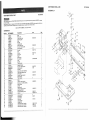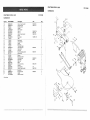
1
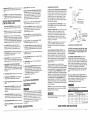
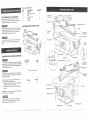
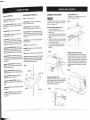
Owner's
Manual
.1/8HP, (Maximum
5" Pin End Blade
Developed)
1725 S.P.M.
scROLL
SAW
Model No.
137.216160
CAUTION:
"
•
•
"
"
Before using this Scroll
Saw,
read this manual and follow
all its safetyRules
and
Operating•
Instructions.
•.
Customer
Safety Instructions
Installation
Operation
Maintenance
,Parts List
Help Line
1-800.843.1682
,,,i
Sears, Roebuck and
Part No, 1372161600001
Co., Hoffman
E
states, IL 601 79USA
.....
PAGE
SECTION
Warranty ................................................................
Product Specifications
.....................................................
Safety _nstructions
........................................................
Accessories
and Attachments
...............................................
Carton Contents
..........................................................
Know Your Scroll Saw .....................................................
Glossary of Terms
........................................................
Assembly
and Adjustments
.................................................
Blade Selection
..........................................................
Operation
..............................................................
Maintenance
...............................
.............................
Troubleshooting
guide ....................................................
Parts ...................................................................
Espahol ................................................................
2
2
3
6
6
7
8
9
13
t4
16
17
18
23
GENERAL SAFETY INSTRUCT_ONS
BEFORE
by power sanding, sawing, grinding, drilling, and other construction
known [to the State of California] to cause cancer, birth defects
reproductive harm.
Some examples of these chemicals are:
€ Lead from lead-based paints.
® Crystalline silica from bricks and cement and other masonry products.
¢ Arsenic and chromium from chemically-treated
lumber,
Your dsk from these exposures varies, depending on how often you do this type of work.
activities
or other
MOTOR
Power source .......
Horsepower ........
Speed ............
BLADE
Type
Depth
Blade
Depth
Depth
120 '7, 60 HZ, 1.0 Amp., AC
1/8 HP (Max. Developed)
1725 S.P.M.
1.
KEEP GUARDS _N PLACE and in working order.
3.
REMOVE ADJUSTING KEYS AND WRENCHES.
Form the habit of checking to see that keys and
adjusting wrenches are removed from the tool before
turning ON.
.............
of Throat .....
Stroke .......
of 45 ° Cut ....
of 90" Cut ....
TABLE
Size ..............
Tilt ...............
SAWDUST
BLOWER
5" Pin end
16"
3/4"
1"
2"
,
To reduce
Your scroll saw is wired at the factory for t20V operation.
Connect to a 120V, 15 Amp branch circuit and use a 15
Amp time delay fuse or circuit breaker. To avoid shock or
fire, replace power cord immediately if it is worn, cut or
damaged in any way.
READ and become familiar with this entire instruction
manual. LEARN the tool's applications, limitations, and
possible hazards.
2.
7.
To avoid electrical hazards, fire hazards, or damage to
the tool, use proper circuit protection.
SAW
To avoid mistakes that could cause serious injury, do not
plug the scroll saw in until you have read and understooa
the following:
,
your exposure to these chemicals:wo.rk
in a well ventilated area, and work with approved safety
equipment, such as those dust masks'that are specially designed to filter out microscopic
particles.
THE SCROLL
Safety is a combination of common sense, staying alert
and knowing how to use your scroll saw.
,
Some dust created
contains chemicals
USING
KEEP WORK AREA CLEAN. Cluttered areas and
benches invite accidents.
DON'T USE iN A DANGEROUS ENVIRONMENT.
Don't use power tools in damp or wet locations, or
expose them to rain. Keep work area well lighted.
KEEP CHILDREN AWAY. All visitors should be kept at
a safe distance from the work area.
MAKE WORKSHOP KID PROOF with padlocks, master
switches, or by removing starter keys.
8.
DON'T FORCE THE TOOL. It will do the job better
and safer at the rate for which it was designed.
9.
USE THE RIGHT TOOL. Don't force tool or the
attachment to do a job for which it was not designed.
t0. USE PROPER EXTENSION CORD. Make sure your
extension cord is in good condition. When using an
extension cord, be sure to use one heavy enough to
carry the current your product will draw. An undersized
cord wilt cause a drop in line voltage resulting in loss
of power and overheating. The table on page 7 shows
the correct size to use depending on cord length and
nameplate ampere rating. If in doubt, use the next
heavier gauge. The smaller the gauge number, the
heavier the cord.
11. WEAR PROPER APPAREL. DO NOT wear loose
clothing, gloves, neckties, rings, bracelets, or other
jewelry which may get caught in moving parts.
Nonslip footwear is recommended. Wear protective
hair covering to contain long hair.
12.
WEAR_OUR
ALWAYS WEAR EYE
PROTECTION. Any scroll
saw can throw foreign
objects into the eyes which
could cause permanent eye
damage. ALWAYS wear
Safety Goggles (not glasses)
that comply with ANSI safety standard Z87.1.
Everyday eyeglasses have only impact-resistant
lenses. They ARE NOT safety glasses. Safety
Goggles are available at Sears. NOTE: Glasses or
goggles not in compliance with ANSI Z87.l could
seriously hurt you when they break.
13. WEAR A FACE MASK OR DUST MASK.
Sawing operation produces dust.
14. SECURE WORK. Use clamps or a vise to hold work
when practical. It's safer than using your hand and it
frees both hands to operate tool.
15. DISCONNECT TOOLS before servicing, and when
changing accessories, such as blades, bits, cutters,
and the like.
t6. REDUCE THE RISK OF UNINTENTIONAL STARTING.
Make sure the switch is in OFF position before
plugging in.
17. USE RECOMMENDED ACCESSORIES. Consult the
owner's manual for the recommended accessories.
The use of improper accessories may cause risk of
injury to persons.
18. NEVER STAND ON TOOL. Serious injury could occur
if the tool is tipped or if the cutting tool is unintentionally
contacted.
19. CHECK FOR DAMAGED PARTS. Before further use of
the tool, a guard or other part that is damaged should
be carefully checked to determine that it will operate
properly and perform its intended function. Check for
alignment of moving parts, binding of moving parts,
breakage of parts, mounting, and any other conditions
that may affect its operation. A guard or other part that
is damaged should be properly repaired or replaced.
20. NEVER LEAVE TOOL RUNNING UNATTENDED°
TURN THE POWER OFR Don't leave the [ool until
it comes to a complete stop.
21. DON'T OVERREACH.
balance at all times.
22. MAINTAIN TOOLS W_TH CARE. Keep tools sharp
and clean for best and safest performance. Follow
instructions for lubricating and changing accessories.
I0-1/4" x 17-1/8"
45 ° Left
...
Yes
SAVE THESE
Keep proper footing and
NSTRUCT ONS
23. DIRECTION OF FEED. Feed work into a blade or cutter
against the direction of rotation of the blade or cutter
only.
24. WARNING: Dust generated from certain materials can
be injurious to your health. Always operate saw in well
ventilated areas and provide for proper dust removal.
SPE( IFIC SAFETY INSTRUCTIONS
FOR THE SCROLL SAW
READ AND UNDERSTAND all safety instructions
and operating procedures throughout the manual.
t.
DO NOT operate the scroll saw until it is completely
assembled and installed according to 'theinstructions.
,2.
SHOULD any part of your scroll saw be missing,
damaged, or fail in any way, or any electrical component
fail to perform properly, shut off the switch and remove
the plug from the power supply outlet. Replace missing,
damaged, or failed parts before resuming operation.
3.
IF YOU ARE NOT thoroughly familiar with the
operation of scroll saws, obtain advice from your
supervisor, instructor, or other qualified person.
.
SERIOUS INJURY could occur if the tool tips over or
you accidentally hit the cutting to0t. Do not store
anything above or near the tool.
5_
,
,
.
9.
AVOID INJURY from unexpected saw movement.
Place the saw on a fir m level surface where thesaw
does not rock, and bolt or clamp the saw to its support..
YOUR SCROLL SAW
FASTENED to a stand
tendency for the stand
operation, the stand or
to the floor.
MUST BE SECURELY
or workbench. !f there is any
or workbench to move during
workbench MUST be fastened
THiS SCROLL SAW is intended for indoor use only.
TENSION BLADE PROPERLY before starting the
saw. Recheck and adjust tension as needed.
15.
DO NOT USE dull or bent blades.
TURN THE SAW OFF AND UNPLUG THE CORD if
16. the blade binds in the saw kerf while being backed
out of the workplace, usually caused by sawd0st
clogging the kerf. If this happens, turn off the scroll
saw and unplug the power cord. Wedge open the
kerf and back the blade out of the workplace.
17. DO NOT feed the material too fast while cutting. Only
feed the workplace at the rate the saw will cut.
t8. TURN THE POWER OFF, remove the switch key and
make Sure the scroll saw comes to a compiete stop
before installing or removing an accessory, and
before leaving the work area.
19. DO NOT START the saw with workplace pressing
against the blade. Slowly feed the workplace into the
moving blade.
20. WHEN CUTTING a targe workpiece MAKE SURE
the material is supported at table height.
21. EXERCISE CAUTION when cutting workpieces that
are round or irregularly shaped. Round items will roll
and irregularly shaped workpieces can pinch the blade.
22. ALWAYS release blade tension before loosening the
blade holder screw.
23. MAKE CERTAIN table tilting lock is tightened before
starting the machine.
24. NEVER REACH under the scroll Saw table when
motor is running.
25. CHECK FOR DAMAGED PARTS before each use.
Check for alignment of moving parts, binding of
moving parts, breakage of parts, mounting or any
other conditions that may affect operation, Parts that
are damaged should be properly repaired or
reptaced before using the toot.
26. THINKSAFETY.
ELECTRICAL
10. BLADE TEETH MUST POINT downward toward the
table.
11 . TABLE MUST BE CLEARED of all debris before
operating saw. Do not perform layout, set up or
assemble work on the table when the saw is in
operation.
12. TO PREVENT INJURIES, avoid awkward hand or
finger positions, where a sudden slip could cause a
hand to move into the blade when operating the saw.
13. HOLD WORKPIECE
FIRMLY against the table top.
i4. NEVER CUT MATERIAL that is too small to be held
safely.
REQUIREMENTS
POWER SUPPLY AND MOTOR
SPECIFICATIONS
To avoid electrical hazards, fire hazards, or damage to
the tool, use proper circuit protection. Use a separate
electrical circuit for your tools.Your saw is wired at the
factory for 120V operation. Connect to a 120V, 15 Amp
circuit and use a 15 Amp time delay fuse or circuit
breaker. To avoid shock or fire, if power cord is worn or
cut, or damaged in any way, have it replaced
immediately.
GROUNDING
INSTRUCTIONS
Fig. A
IN THE EVENT OF A MALFUNCTION OR BREAKDOWN,
3-Prong Plug
grounding provides a path of least resistance for electric
current and reduces the risk of electric shock. This tool
is equipped with an electric cord that has an equipment
grounding conductor and a grounding plug: The plug
MUST be plugged into a matching receptacle that is
properly installed and grounded in accordance with ALL
local codes and ordinances.
DO NOT MODIFYTHE
_3.
g
pac
PLUG PROVIDED. If it will not
fit the receptacle, have the proper receptacle installed
by a qualified electrician.
Fig. B
Grounding Lug
IMPROPER CONNECTION of the equipment grounding
conductor can result in risk d electric shock. The
conductor with the green insulation (with or without
yellow stripes) is the equipment grounding conductor, if
repair or replacement of the electric cord or plug is
necessary, DO NOT connect the.equipment grounding
conductor to a live terminal.
-- Make Sure This
is Connected to a
Known Ground
2-Prong
Receptacle
Adapter
CHECK with a qualified electrician or service person if
you do not completely understand the grounding
instructions, or if you are not sure the tool is properly
grounded.
GUIDELINES FOR EXTENSION CORDS
USE ONLY 3-wire extension cords that have 3-prong
grounding plugs and 3-pole receptacles that accept
the tool's plug. Repair or replace damaged or worn
cord immediately.
USE A SEPARATE ELECTRICAL CIRCUIT for your
tools. This circuit must not be less than #12 wire and
should be protected with a 15 Amp time delay fuse.
Before connecting the motor to the power line, make
sure the switch is in the OFF position and the electric
current is rated the same as the current stamped on the
motor nameplate. Running at a lower voltage will
damage the motor.
USE PROPER EXTENSION CORD. Make sure your
extension cord is in good condition. When using an
extension cord, be sure to use one t_eavy enough to carry
the current your product will draw. An undersized cord will
result in a drop in line voltage and in loss of power which
will cause the tool to overheat. The table below shows the
correct size to use depending on cord length and
nameplate ampere rating. If in doubt, use the next heavier
gauge. The smaller the gauge number, the heavier the
cord.
This tool is intended for use on a circuit that has a
receptacle like the one illustrated in FIGURE A. FIGURE
A shows a 3-prong electrical plug and receptacle that has
a grounding conductor. If a properly grounded.receptacle
is not available, an adapter (FIGUREB) can be.used to
temporarily connect this plug to a 2-contact ungrounded
receptacle. The temporary adapter should be used only
until a properly grounded receptacle can be installed by
a qualified technician. The adapter (FIGURE B) has a
rigid lug extending from it that MUST be connected to a
permanent earth ground, such as aproperly grounded
receptacle box. The Canadian Electrical Code prohibits
the use of adapters.
Be sure your extension cord is properly wired and in
good condition. Always replace a damaged extension cord
or have it repaired by a qualified person before using it.
Protect your extension cords from sharp objects,
excessive heat and damp or wet areas.
-CAUTION: In all cases, make certain the receptacle is
properly grounded. If you are not sure have a qualified
electrician check the receptacle.
This tool must be grounded while in use to protect the
operator from electrical shock.
(when
Ampere
This scroll saw is for indoor use only. Do not expose to
rain or use in damp locations.
Rating
using
Total
0
6
25'.
18
6
!0
18
more
than
t_ol
10
12
12
- 16
more
than
16
14
120 vofts
length
only)
of cord
in feet
100'
16
150'
14
16
14
12
16
14
12
Not
12
Recommended
SAVE THESE INSTRUCTIONS
SAVE THESE iNSTRUCTiONS
:,: ::::?
::::::::::::::::::::::::::::::::::::::::::::::::::::::::::::::::::::::::::::::::::::::::
5
j
50'
!6
:::::::::::::::::::::::::::::::::::::::::::::::::::::::::::::::::::::::::::::::
:'
j
!
4
i
J
TABLE OF LOOSE PARTS
RECOMMENDED
ACCESSORIES
Visit your Sears Hardware Department or see the
Craftsman Power and Hand Tools Catalog to purchase
recommended accessories for this power tool.
ITEM
A.
B.
C.
D.
E.
K
QUANTITY
1
4
1
1
2
t
Scroll saw
Blades (Pin type only)
Knob
Dust blower tube
Saddles
T-wrench
Quick release
tension _ever
Bellows seat
dust blower
-Dust bJower knob
Saddles
%wrench
UNPACKING
YOUR SCROLL
SAW
Do not attempt to modify this tool or create accessories not
recommended for use with this tool. Any such alteration or
modification is misuse and could result in a hazardous
condition leading to possible serious injury.
Upper blade holder
Blade
T-wrench
holder
Blade guard
held-down
Work table
To avoid the risk of personal injury, do not modify this
power tool or use accessories not recommended by
Sears.
Arm bearing
Table stop
lock nut
UNPACKING AND CHECKING CONTENTS
Warning label
Mounting hole
To avoid injury from unexpected starting, do not plug the
power cord into a power source receptacle during unpacking
and assembly. This cord must remain unplugged whenever
you are working on the saw.
Sawdust port
Lower blade holder
B
C
Table stop
adjusting screw
storage
If any part is missing or damaged, do not plug the scrol!
saw in until the missing or damaged part is replaced, and
assembly is complete.
Carefully unpack the scroll saw and all its parts, and
compare against the illustration below.
1. Remove the scroll saw from the cartonby lifting the
saw by the back of the upper frame. _!
2. Place the saw on a secure surface and examine it
carefully.
D
Specification
data plate
E
F
Bevel
..... Motor
Bevel scale
CAUTION: Do not ffft this saw by the arm that holds the
blade, or the saw will be damaged.
Table lock handl,
To avoid fire and toxic reaction, never use gasoline,
naphtha, acetone, lacquer, thinner, or similar highly
volatile solvents to clean the scrotl saw.
ON/OFF switch
Mounting hole
Power cord
i::i_i,:_i!i:!_::_!:_:'i_:i_i_!:;:i_:
¸!if!i:!
¸ii;:i!!i;_it,!:!:;ii_:ii:!i;ii:!i::'il
¸:!;:i'_::,ii•:::
:!:!i_
¸i_:_i!i':!_i;_;_i_:::•:;!:::'i
¸I¸:11:!i_:I:!I!I!!_i:_:::!_II::_I:_I:;:;_!:::_
;!_!;:i:!:ii::'!_i_i:_i!i!:i_;i_i_:i::i:!ii:::i
_i
_;•:i_::i:i:::ii!:i_:!i_ii_i:,!!i!:i_i:::!i
_i!i;!;:_:!_:i:i!!_J::ili!_!;:ii_i::_!!!i:i:;:i:::!i_iii::_!iJ:_!;!:!;:_:_:;_
7 ::::::::::::::::::::::::::::::::::::::::::::::::::::::::::::::::::::::::::::::::::::::::::::::::::::::::::::::::::::::::::::::
SCROLL SAW TERMS
WOODWORKING
BEVEL ANGLE SCALE - Represents the degree of
table angle, from 0 to 45 degrees.
KERF - The s_ot cut by the blade.
BLADE GUARD HOLD-DOWN - Keeps your work piece
from raising up from the table While performing cutting
operations.
BLADE HOLDERS - Retains and positions blades.
BLADE STORAGE - Provides convenient easy access
to extra pin blades or wrencheS.
ON-OFF SWITCH -The switch has a locking feature
intended to help prevent unauthorized and hazardous
use by children and others. Insert the key into the switch
and push to the ON position to turn the scroll saw on.
QUICK RELEASE TENSION LEVER ' Quickly loosens
and retightensthe blade to itS original tension. The tension
lever quickly sets and resets the blade tension when
performing interior cutting operations or changing blade&
TERMS
(FIG. A)
ASSEMBLY
LEADING EDGE-The
front edge of the workplace
which is pushed into the blade.
SAW BLADE PATH - Area or line of sight of the
workpiece moving in line toward the saw blade edge.
SAWDUST COLLECTION PORT -Allows vacuum
attachments or hose to be used to remove the sawdust
from under the table and base.
4
TABLE LOCK HANDLE - Securely locks table at the
angle desired for angle or bevel cutting.
TABLE STOP ADJUSTING SCREW -Allows easy
adjustment to ensure the table is set perpendicular to the
blade.
T-WRENCH HEX KEY - Is used to tighten hex bolts if they
become loose.
T-WRENCH STORAGE -Allows quick.easy storage of
the T.wrench when changing blades to avoid loss or
misplacement,
Fig. D
,•
Place one saddle (3) on each side of the tubing. The
tube should pass through the holes formed by the
saddles.
.
Thread the dust btower knob (4) through the saddle
assembly and screw into the ho_e (5)on the upper
arm of the scroll saw. Tighten.
For best results, the dust blower tube shoutd be
adjusted to direct air at both the blade and the
workpiece.
Fig. B
SAWDUST COLLECTION PORT (FIG. E)
This scroll saw allows a hose or vacuum accessory (not
provided) to be connected to the port (1) on the left side
of base. If excessive sawdust buildup occurs inside the
base use a wet / dry vacuum cleaner or manuatty remove
sawdust by removing the screws and metal plate (2) on
the left side of saw. Reattach the metal plate and screws
before starting the saw, This will keep your saw cutting
efficiently,
DEFLECTION - Slight movement of blade in the horizontal
direction while the blade is moving inline during cutting
operations, This may be caused by the blade following
the grain orthe path of least resistance,
Fig. A
STROKES PER MINUTE (SPM) - Speed of the saw
blade measured by the count of its reciprocating actions.
Leading Edge
rf
Fig. E
Saw blade Path
Surface
STORING THE T-WRENCH (FIG. C)
The left rear side of the body (1) has a U-shaped damp holder (2) designed to store the T-shaped hex wrench (3).
Position the shaft of the T-wrench handie into the
U-shaped c_amp holder as shown.
Workpiece
Trailing Edge
(FIG. D)
INSTALLING THE DUST BLOWER (FIG. B)
1. Locate the dust blower tubing (1).
2. Connect the PVC plastic end of the tube to the
bellows seat (2).
TRAILING EDGE -The end of the workpie.ce edge last
cut by the saw blade.
FEED - Rate of moving material to be cut into the blade.
SAWDUST BLOWER - Keeps sawdust from Covering
the line of sight for more accurate cuts. The best results
occur when the blower tube is directed toward the blade
and workpiece.
To avoid injury, •make sure all parts are assembled and
adjusted properly before plugging into a power source
outlet or turning this saw ON.
3.
WORKPIECE - Material on which the cutting operation
is being performed,
BLADE STORAGE
The right side (1) of the scroll saw body has a tray (2)
suitable for storage of saw blades,
BLADE TOOTH SET - The total width the blade will cut
based on the distance from the outside point of one bent
tooth to the outside point of the next bent tooth establishing
set of teeth.
SURFACE -Top of workpiece being cut.
INSTRUCTIONS
Fig. C
'
3
2
1
/
"_
e
PIN-ENDBLADE
REMOVAL AND _NSTALLATION
PIN-END BLADE INSTALLATION
(FIG. I, J, K, L, AND M)
Fig. G
CAUTION: In order to avoid uncontrollable lifting of the
workpiece, the teeth of the blade should ALWAYS point
downward.
To prevent personal injury always turn saw OFF and
disconnect the plug from the power source before
changing blades or making adjustments.
1.
NOTE: This machine uses only pin-end blades.
Pin-end type blades are thicker for stability and for faster
assembly. They provide faster cutting on a variety of
materials.
To install the blade (1), loosen the tension on it by first
liftingup the quick release tension lever (2). (FIG. 1)
Fig. I
NOTE: When installing pin-end blades, the slot must be
slightly wider than the thickness of the blade. After the
blade is installed, the blade tension mechanism will keep
it in place.
,
Hook the lower blade pin in the pin recess of the
lower blade holder (5) first, and then the upper blade
holder (6). (FIG. L)
NOTE: Apply slight downward pressure against the
upper arm when installing the blade in the upper
blade holder.
PIN-END BLADE REMOVAL (FroG.F, G, and H)
1. To remove the blade (1), loosen the tension on it by
first lifting up the quick release tension lever (2).
(FIG. F)
Fig. L
4.
Fig. F
Fig. K
2.
Lift the blade through the table access hote (7).
(FIG. H)
NOTE: Apply slight downward pressure against the
upper arm when removing the blade from the upper
blade holder.
3.
:!i
Level the table (3) to a 0 degree horizontal angle to
view the lower blade holder (5), and lock the bevel
lock handle (4). (FIG. J)
Notice that the blade holders have blade slots and pin
recesses for both forward and side cutting positions. Decide which position you will be using.
NOTE: Cutting from the side is necessary if your
workpiece exceeds 16 inches in length.
Fig. H
7
CAUTION: For side-cutting, the table must be used at
a 0 ° bevel angle.
,,
,
,,,
Fig.J
,
=
To view lower blade holder (5), level the table (3) to a
0 degree horizontal angle and lock the bevel lock
handle (4). (FIG, G)
Remove the blade from the upper (6) and lower
blade holder (5) by pUlling and liftingthe blade
forward to release it fromthe upper and lower pin
recesses, If the blade was installed for side-cutting,
lift the blade to the side to remove it from the side
blade recesses.
.
Lower the quick release tension lever (2) to tension
the blade. If the tension is too tight, turn
counterclockwise, ff too loose, turn the lever
clockwise. (FIG. M)
Fig. M
4.
Insert one end of the blade through the table access
hole (7). (FIG. K)
ADJ USTMENT
INSTRUCTIONS
SQUARING THE TABLE
MOUNTINGTHE SCROLL SAW (FIG. Q)
1. To-mount your scroll saw in a permanent location
such as a sturdy workbench, bolt the scroll saw base to
a solid workbench top. The'scroll saw base (1) has 4
mounting holes.
2. Place the Scroll Saw on the work surface (5), mark
the holes on the work surface and drill 3/8" holes.
Use bolts, washers, nuts to secure.
3. if the workbench moves or shakes during operation,
it must be fastened to the floor.
4., Your scrofl saw is designed to be used on horizontal
surfaces only. Motor damage may result when mounted
on a non-horizontal surface.
Fig. O
5
(FIG. N, O, and P)
NOTE: Your scroll saw has 'been adjusted but should be
rechecked prior to use for best operation.
1.
Remove the hold-down blade guard (1) by pulling the
side pegs (2) out of the holes in the scroll saw body.
(Fig. N)
Fig. N
2
Fig. Q
9
1.
2.
3.
4.
5.
6.
7.
8.
9.
3.
4.
5.
6.
7.
Loosen the table bevel lock handle (3) and move the
table (4) until it is or at a right angle to the blade (5).
(Fig. O)
Loosen the locking nut (6) on the adjusting screw (7)
under the table by turning counterclockwise.
Lower the adjusting screw by turning clockwise.
Use a small square (8) on the table and against the
blade, as shown. Set the table at 90 degrees to the
blade. If there is space between the square and
blade, adjust the table angle until the space is removed.
Lock the table bevel lock handle (3) under the table
to secure movement. Raise the adjusting screw (7)
by turning counterclockwise untit the top end of the
screw touches the table.
Tighten the locking-nut (6) by turning clockwise.
To avoid injury from accidental starting, always turn switch
OFF and unplug the scroll saw before moving, replacing
the blade or making adjustments.
This scroll saw accepts 5" length pin end blades with a
wide variety of b_ade thicknesses and widths. The type of
material and intricacies of cutting operations (size of radius
or curves) will determine the number of teeth per inch.
As a general rule, always select the narrowest blades for
intricate curve cutting and the widest blades for straight
and large Curve cutting operations. The following table
represents suggestions for various materials. When
purchasing blades, refer to the back of the package for
best use of blades on various materials. Use this table as
an example, but practice and your own personal preference
will be the best selection method.
8
Fig. R
9
®/
2.
Scroll saw
Hex head bolt
Rubber washer
Flatwasher
Workbench
Flatwasher
Lockwasher
Hex nut
Jamb nut
3LADE SELECTION (FIG. R)
SAWDUST BLOWER (FIG. P)
Adjust the sawdust blower tube (1) to point to the blade
and workpiece:
1. Loosenthe knob (2)
2. Move the tube through the saddles (3) to aim the
nozzle at the blade and hold-down foot (4).
NOTE: The tube's function is to blow the sawdust off
the line of sight when cutting, It is not designed to blow
all of the sawdust off the table.
9.5-15
TEETH/
INCH
TPI
10-15
Fig. P
2
3
30
BLADE
BLADE BLADE/
WIDTH THICKNESS SPM
INCH
INCH
0.110
0.018
48
MATERIAL
CUT
Mediumturns on
400-1200 t/4" to 1-3/4" wood,
Isoft metal, hardwood
1
15-28
NOTE: Avoid setting edge of table against top of
motor which could cause noise when saw is running.
8_
15-28
Loosen the screw holding the bevel scale pointer (9)
and adjust the pointer to 0 degrees. Tighten the
iSmalt turns on 1/8" to
.055-.110 .010-.018 800-I800 1-1/2" wood, soft metal
hardwood
30-48 ..024-,041 .012-.019
screw.
Varies
Non-ferrous
metals/hardwoods
lusing very slow speeds
10. Reattach the hold-down blade guard (2) by placing
the pegs into the side holes in the saw body. (Fig. N)
NOTE: Remember the bevel scale is a convenient
guide but should not be relied upon for precision.
NOTE: Thinner blades will have more possibilities for _
blade deflection when cutting angles are not perpendicular
to the table, Read BASIC SCROLL SAW OPERATION
for more suggestions.
13
ANGLE CUTTING
11. This saw uses 5 inch long pin type btaae._ only.
Toavoidinjuryfrom.accidenta!
starting,alwaysturnswitch
OFFandunplugthe scrollsawbeforemoving,.replacing
the bladeor makingadjustments.
A scroll saw is basically a curve cutting machine. It
_an also be used for Straight cutting and beveling or
angle cutting operations. Please read and understand
the following items abou t your scroll saw before
attempting to use the saw.
_.!ECOMMENDATIONS
FOR CUTTING
When feeding the workpiece into the blade do not
force the leading edge of the workpiece into the blade
because the blade will deflect, reducing the accuracy
of cut and possibly breaking the blade. Allow the saw
to cut material by guiding the workpiece into the blade
as it cuts.
T
2.
12. Blades wear faster when cutting plywood or particle
board which is very abrasive. Angle cutting in
hardwoods reduces blade set faster due to the blade
deflection.
FREEHAND CUTTING
To avoid injury from accidental starting, always turn switch
OFF and unplug the scroll saw before moving, replacing
the blade or making adjustments.
Draw your design on the workpiece or secure a
design to the workpiece (1).
Raise the blade guard assembly (2) by lifting.
Position the workpiece against the blade (3) and
place the blade guard hold-down foot against the top
surface of the workpiece.
2.
3.
There is a learning curve for each person who wants
to use this saw. During that period of time it is expected
that some blades will break until you learn how to use
the saw and receive the greatest benefit from the blades.
.
Best results are achieved when cutting wood less than
one inch thick.
.
8.
g.
• Teeth on scroll saw blades wear out and must be
replaced frequently for best cutting results. Scroll saw
blades generally stay sharp for 1/2 to 2 hours of
cutting.
5_
CAUTION: Do not force the leading edge of
workpiece into the blade because the blade will
deflect, reducing accuracy of cut and possibly
breaking the blade.
.
When the cut is complete, move the trailing edge of
the workpiece beyond the hold-down foot before
turning the scroll saw OFR
or beeswax.
10. When choosing a blade to use with your scroll saw,
consider very fine, narrow blades to scroll cut in thin
wood 1/4" thick or tess. Use wider blades for thicker
materials but this will reduce the ability to cut tight
curves.
Fig. T
2.
3.
4.
6.
5
CAUTION: In order to avoid uncontrollable lifting of
the workpiece and reduce blade breakage; do not
pull the control knob ON while the workpiece is
against the blade.
.
Position the workpiece against the scrap wood (2)
prior to touching the leading edge of the workpiece
against the blade (1).
Slowly feed the workpiece into the blade, guiding the
workpiece against the straight edge of the scrap
wood. Press the workpiece down against the table
while cutting.
!0. When the cut is complete, move the trailing edge of
the workpiece beyond the hold-down foot.
Turn the scroll saw switch OFR
NOTE: When cutting a narrow workpiece use push
sticks.
@
Fig. U
2
3
RiP OR STRAIGHT
LiNE CUTTING
(FIG. U)
To avoid injUry from accidental starting, always turn the
switch OFF and unplug the scroll saw before moving,
replacing the blade, or making adjustments.
2
Measure from the inside tip of the blade (1) to the
desired distance and position scrap wood (2) parallel
to the blade.
Clamp the scrap wood to the table (3).
Recheck your measurements, using the workpiece (4)
to be cut, and make sure the scrap wood is secure.
Position the workpiece against the blade, placing the
hold-down foot (5) against the top surface of the
workpiece.
Remove the workpiece from the blade prior to
turning the scroll saw ON.
CAUTION:
Do not force the leading edge of
workpiece into the blade because the blade will
deflect, reducing accuracy of cut and possibly
breaking the blade.
Fig. S
To get accurate cuts be prepared to compensate for
the blade's tendency to follow the wood grain as you
are cutting.
This scroll saw is intended to cut wood or wood
products. Precious and non-ferrous metals perform
well on scroll saws that have very slow speed
capebi!ity, and should be lubricated with machine oil
6.
Before turning the Scroll saw ON, position a piece of
scrap wood (4) against and ahead of the workpiece.
Cut the scrap before-cutting into the leading edge of
the workpiece (1).
Slowly feed the workpiece into the blade, guiding and
pressing the workpiece down against the table.
,
when cutting wood thicker than one inch the user
must guide the wood very, very slowly into the blade
and take extra care not to bend or twist the blade
while cutting in order to maximize blade life.
6.
2.
Draw your design on the workpiece or secure a design
to the workpiece (i).
Loosen the bevel lock handle (2) and move the table
to the proper angle, using the degree scale (3) and
the pointer (4).
Tighten the bevel lock handle securely.
Lift the blade guard (5).
Position the workpiece on the right side of the
blade (6) and lower the blade guard hold-down foot
against the surface,
Follow items 4-6 under FREEHAND CUTTING
OPERATIONS.
CAUTION: In order to avoid uncontrollable lifting of
the workpiece and reduce blade breakage, do not
turn the switch ON while the workpiece is against the
blade.
You must guide the wood into the blade slowly because
the teeth of the blade are very small and they can
only remove wood when they are on the down stroke.
.
1.
1.
g.
1.
The blade teeth cut matedal ONLY on the down stroke.
.
(FiG.T)
To avoid injury from accidental starting, always turn the
switch OFF and unplug the scroll saw before moving,
replacing the blade or making adjustments.
3.
4,
5.
(FIG. S)
(BEVEL CUTTING)
Tools Needed
4
QUANTITY
DESCRIPTION
2
Small C-clamps
t
Ruler or measuring tape
I
12=''Siiaight scrap OfW00d
(Thickness to match workpiece)
INTERIOR CUTTING
(FIG.V)
To avoid injury from accidentaf starting, always turn
switch OFF and unplug the scroll saw before moving,
replacing the blade, or making adjustments.
1.
2.
3.
4.
Draw your design or secure a design to a
workpiece (1). Drill a 1/4 inch hole in the workpiece
to perform inside cutting."
Raise the quick release tension lever (2) and remove
the blade (3). Refer to BLADE REMOVAL AND
INSTALLATION (page 11).
Place the workpiece on the saw table with the hole (4)
in the board over the access hole in the table.
Install the blade (3) through the hole in the board (4)
and lower the quick refease tension lever (2).
CAUTION: To avoid uncontrollable lifting of the
workpiece and to reduce blade breakage, do not turn
the scroll saw ON while the blade is against the wood.
5.
6.
Position the workpiece so the blade is not touching
the wood and turn the scroll saw ON.
Slowly feed the workpiece into the blade, guiding
and pressing the workpiece down against the table.
CAUTION: Do not force the workpiece into the
blade. The blade will deflect, reducing accuracy of
cut and possibly breaking the blade,
7.
When finished making the interior scroll cuts simply
turn the scroll saw OFF, remove the blade from the
blade holder, and remove the workpiece from the
table.
TROUBLESHOOTBNG
For your own safety, turn the switch .OFF and remove the
plug from the power source before maintaining or
lubricating your saw.
To avoid injury from an accidental start, turn the switch OFF and always remove the plug from the power source
before making any adjustments.
Consult your Sears Service Center if for any reason the motor will not run.
GENERAL
An occasional coat of paste wax on the work tame will
allow the wood being cut to glide smoothly across the
work surface.
MOTOR
1. If the power cord is worn, cut_ or damaged in any
way, have it replaced immediately.
2. Do not attempt to oil the motor bearings or service
the motor internal parts.
ARM BEARINGS
(FIG.W)
Lubricate the arm bearings after every 50 hours of use.
1. Turn the saw on its side.
2. Squirt a generous amount of SAE 20 (lightweight)
oil (1) around the shaft end.and bronze bearing (2),
3. Let the oil soak in overnight, keeping the saw in this
position.
4. The next day repeat the above procedures for the
opposite side of the saw.
Fig. W
GUIDE
PROBLEM
PROBABLE CAUSE
REMEDY SUGGESTED
Breaking blades.
1.
2.
3.
4.
1. Adjust blade tension.
2, Reduce feed rate.
3. Use narrow blades.
Motor will not run.
Wrong tension.
Overworking blades.
Wrong blade application.
Twisting blade in wood.
!. Defective cord or plug.
2. Defective motor.
i
I
3. Blown overload breaker.
Excessive vibration.
NOTE: There will always
be some vibration present
when the saw is running
because of motor operation.
t. Improper mounting of saw.
2. Unsuitable mounting surface.
Fig. V
3. Loose table or table resting
against motor.
4. Loose motor mounting.
2
4.
Avoid side pressure on blade.
I.
Replace defective parts before using saw
again,
2, Call Sears Service Center. Any attempt to
repair this motor may create a HAZARD unless
repair is done by a qualified service technician.
3. Push the power switch to the OFF position.
Let the motor cool.
1, See mounting instructions in this manual for
proper mounting technique.
2. The heavier your work bench is the less
vibration will occur, A plywood workbench will
not be as good work surface as the same
size solid lumber, Use common sense in
choosing a mounting surface,
3, Tighten table lock knob.
4. Tighten motor mounting screws,
........ , ...............
Blade run out.
Blade not in line with arm
motion.
1
1, Blade holders not aligned.
2
.
,,,,, ,.
.......
•Loosen cap screws holding blade holders to
arms. Adjust position of blade holders.
Retighten cap screws.
4
FULL ONE YEAR WARRANTY
iJ
If this product fails due to a defect in material or workmanship within one year from the date of purchase, Sears
will repair it free of charge.
Contact a Sears Service Center for repair.
If this product is used for commercia! or rental purposes, this warranty appties only for 90 days from the date of
purchase.
This warranty gives you specific legal rights, and you may also have other rights which vary from state to state.
Sears, Roebuck and Co., Dept. 817 WA, Hoffman Estates, IL 60179
::)
CRAFTSMAN
SCHEMATIC
CRAFTSMAN
ii:
SCROLL
SCROLL
SAW
137.216160
A
137,216160
SAW
When servicing use only CRAFTSMAN replacement parts. Use of any other parts may create a HAZARD or cause
product damage.
Any attempt to repair or replace electrical parts on this scroll saw may create a HAZARD unless repair is done by a
qualified service technician. Repair service is available at your nearest Sears Service Center,
Order by PART NUMBER, not by key number
iJ
SCHEMATIC
A
Key No.
PART NUMBER
Description
1
2
3
4
5
6
7
8
9
10
11
12
13
14
15
16
17
18
19
Size
17100101
17100206
2608BBLA32
17107029
17100407
17100501
18506616
2608BBLA32
17100801
2502NBC406
2701FBD106
17101301
2701FBD106
2536MBE603
17109901
18109301
2501NBDN27
18112501
18109201
Base
Plate cover
Truss head screw
Warning label
Body
Bumper
Caution label
Truss head screw
Hex soc. head cap bolt
Spring washer
Hex nut
Bush
Hex nut
Spring pin
Knob
Shaft-pivot
Flat washer
Bush
Spacker
M5x0.8-10
M5x0.8-10
1/4
M6xl T=5
M6xl T=5
3-16
5116x718-5164
.
Qty.
I
I
3
I
i
I
I
3
2
I
27
1
2
1
1
1
I
!
1
1
5
_£.......................
_£_o_ ............................................
_.!_m_.b£!_...............................................................................................................................
!.........
21
22
23
24
25
26
27
28
29
17101901
2602BBLA09
2502NBC402
14706601
17102302A1
26600PBCK12
17103201
2602BBLA07
17102601
Segment spring
Hex soc. head cap
Spring Washer
Set plate
Upper arm rocker
Truss head tapping
Baffle plate
Hex soc. head cap
Blade holder
bolt
M4x0,7-12
5/32
assembly
screw
M4x18-10
bolt
M4x0.7-8
1
2
2
2
1
2
1
2
1
46-..
44
i,J
.39.
.......................
.2. 0.4.gzc.00.4..
.................................. ....................................................................
4........................................................
........
31
32
33
34
35
36
37
38
39
40
15802103
2602BBLA28
17103401AI
17104401
14701101
17104001
2617BBLC15
15808001
2660MBCE10
2701FBDI05
Blade
Hex soc. head cap bolt
Bottom arm rocker assembly
Blade holder
Washer
Bearing seat
Hex soc head cap screw
Bearing protector
Pan head tapping screw
Hex nut
41
42
43
44
45
46
47
48
49
2502ABC408
2001 ZZ0625
14704901
2705FBD106
14706902
18102102
2615BBDC26
2615BBDC20
2615NBDC01
Spring washer
Ball bearing
Shaft sleeve
Nut chuck
Clamp bolster
Lingager bar
Hex head screw & washer
Hex head screw & washer
Hex head screw & washer
M5x0.8-25
M5x0.8-16
M4x16-8
M5x0,8 T=4
5
625ZZ
M6 T=6
M8x1.25-30
M6x1-25
1/4x20-3/4
6
1
I
I
I
I
I
I
I
I
1
2
!
1
1
1
2
3
4
:i
CRAFTSMAN
SCROLL
SAW
137.216160
SCHEMATmC
B
CRAFTSMAN
SCHEMATIC
SCROLL
SAW
!37.216160
1f3
Key No.
PART NUMgER
Description
Size
50
51
52
53
54
55
56
57
58
59
60
2602BBLA28
2668BBDA39
15805401
17106303
2506MBN606
270t Fi3D105
2701FBD106
2602BBLB44
14703601
2501NBDN 12
17105304
Hex soc. head cap bolt
Pan head screw
Needle pointer
Support
Wave washer
Hex nut
Hex nut
Hex soc head cap bolt
Spring
Flat washer
Table
M5x0.8-25
M6x1.0-12
61
62
63
64
65
66
67
68
69
70
17103302
17106901
17106001
17105602
17116017
2637BBDA23
17111703
17107902
2660MBCE15
19611501
8lade guard
Clamp handle
Saddle
Brass tube
Trade mark label
Truss head screw
Hex wrench
PVC hose
Pan head tapping screw
Bellows seat
71
72
73
74
75
76
77
78
79
18! 23803
17120502
2608BBLA32
2501MBDN05
17!08902
8337D24304
2606BDLA52
14700901
2502NBC406
Bellows
Rocker arm cover
Pan head screw
Flat washer
Safe cover
Motor
Hex soc set screw
Eccentric
Spring washer
81
82
83
*
17105503
2668BBDA23
18504202A1
137216160001
Bracket-tilt
Pan head screw
Handle
Owner's manual
M5x0.8 T=4
M6xl T=5
M6x1.0-35
1t4x518-1/16
M5xO,8-8
M4x16-16
M5x0,8-10
5x10⁻¹
M6x1,25-8
1/4
M5x0.8-8
Qty.
1
1
1
1
2
1
1
t
1.
3
1
1
1
2
I
2
4
1
1
2
1
7O
71
66
73
. 65_
I
J
!
1
1
t
1
1
1
1
1
1
2
1
1
I
61
i
60
v
* Not shown
2_