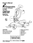
1
Operator's
anuai
3 HP (Ma×. Developed)
10" Baade
4800 R.P,M.
CO POUND
raTERSAW
Model No.
137.212000
CAUTMON:
Safety Instructions
lnstalJation
• Operation
,, Maintenance
,, Parts List
Before using this Miter Saw,
read this manual and follow
all its Safety Rules and
Operating Instructions
Customer
Help
Line
1 =800-843-1682
Sears,
Roebuck
Visit our Craftsman
and Co., Hoffrnan
website:
Part No. 13721200001
Estates,
www.sears.com/craftsman
IlL 60179
U.S.A.
GENERAL
SECTION
PAGE
Warranty ........................................
Product Specifications .......................
Power Tool Safety ............................
Compound Miter Saw Safety ...............
Electrical Requirements and Safety ......
Accessories and Attachments ..............
Tools Needed For Assembly ................
Carton Contents ..............................
2
2
3
4
5
6
6
7
SECTION
Know Your Compound Miter Saw ........
G_ossary of-Terms ............................
Assembly and Adjustments .................
Operation .......................................
Maintenance ...................................
Troubleshooting Guide .......................
Parts List .........................................
PAGE
8
9
10
16
23
24
26
BEFORE
SAFETY
USING
mNSTRUCTMONS
THE M_TER SAW
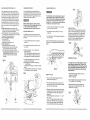
!2.ALWAYS WEAR EYE PROTECTION. Any power
toot can throw foreign objects into the eyes and
could cause permanent eye damage.
ALWAYS wear Safety Goggles {not
glasses) that comply with ANSI Safety
standard Z87.1 Everyday eyeglasses
have only impact - resistance lenses.
They ARE NOT safety glasses. Safety Goggles are
available at Sears. NOTE: Glasses or goggles not in
compliance with ANSI Z87.1 could seriously injure
you when they break.
Safety is a combination of common sense, staying alert
and knowing how to use your miter saw.
To avoid mistakes that could cause serious injury, do
not plug the tool in until you have read and understood
the following.
t. READ and become familiar with the entire
Operators Manual. LEARN the tool's application,
limitations and possible hazards.
If this tool fails due to a defect in material or workmanship
at its option repair or replace it free of charge.
within one year of date of purchase,
Return this tool to a Sears Service Center for repair, or to place of purchase
Sears will
.
for replacement.
This warranty gives you specific legal rights, and you may also have other rights which may vary from
state to state.
Sears, Roebuck and Co., Dept. 8-I7 WA, Hoffman Estates, fL 60179
Some dust created by power sanding, sawing, grinding, drillin_ ! and other construction activities contains
chemicals known (to the State of California) to cause cancer, birth defects or other reproductive harm. Some
examples of these chemicals are:
o Lead from lead-based paints
Crystalline silica from bricks, cement and other masonry products
•
Arsenic and chromium from chemically treated lumber
Your risk from these exposures varies, depending on how often you do this type of work. To reduce your
exposure to these chemicals, work in a wel! ventnated area and work with approved safety equipment such as dust
masks that are specially designed to filter out microscopic particles.
To avoid electrical
120 V AC, 60HZ, 15 Amp
3HP (Max. Developed)
4800 RPM (No load)
Electric
Yes
2-518" x
2_5/8" x
1-1/2" x
1_112"x
5-112"
3-1/2"
5-1/2"
3-tt2"
Rotating Table:
Diameter ..............................
Miter Detent Stops ..................
Bevel Positive Stops ...............
Base Dimensions ..................
Dust Collection ......................
Extension Wings ....................
Net Weight ...........................
REMOVE ADJUSTING KEYS AND WRENCHES.
Form the habit of checking to see that keys and
adjusting wrenches are removed from the tool
before turning ON.
14.SECURE WORK. Use clamps or a vise to hold work
when practical, lt's safer than using your hand and it
frees both hands to operate tool.
15.DISCONNECT TOOLS before servicing, and when
changing accessories such as blades, bits and
cutters.
4. KEEP WORK AREA CLEAN. Cluttered areas and
benches invite accidents.
.
MOTOR
Power Source .....................
Horsepower ........................
Speed .................................
Brake .................................
Doubte insulated ....................
MITER SAW
Cutting Capacity:
Crosscut ............................
Miter 45 o R.&L .....................
Bevel 45 ° L........................
45 ° Miter and 45 ° Bevel .........
13.WEAR A FACE MASK OR DUST MASK. Sawing
operation produces dust.
2. KEEP GUARDS IN PLACE and in working order.
FULL ONE YEAR WARRANTY
.
DON'T USE IN DANGEROUS ENVIRONMENT.
Don't use power tools in damp locations, or expose
them to rain or snow. Keep work area well lighted.
1&REDUCE THE RISK OF UNINTENTIONAL
STARTING. Make sure switch is in OFF position
before plugging in.
KEEP CHILDREN AWAY. All visitors and
bystanders should be kept a safe distance from
work area.
17.USE RECOMMENDED ACCESSORIES. Consult
this Operators Manual for recommended
accessories. The use of improper accessories may
cause risk of injury to yourself or others.
7. MAKE WORKSHOP CHILD PROOF with padlocks,
master switches, or by removing starter keys.
18.NEVER STAND ON TOOL, Serious injury could
occur if the tool is tipped or if the cutting tool is
unintentionally contacted.
8. DON'T FORCE THE TOOL. It will do the job better
and safer at the rate for which it was designed.
1&CHECK FOR DAMAGED PARTS. Before further
use of the tool, a guard or other part that is
damaged should be carefully checked to determine
that it will operate properly and perform its intended
function - check for alignment of moving parts,
binding of moving pads, breakage of parts,
mounting, and any other conditions that may affect
its operation. A guard or other part that is damaged
should be properly repaired or replaced.
9. USE THE RIGHT TOOL. Do not force tool or
attachment to do a job for which it was not designed.
12-5/8"
0, 15, 22-112, 3t.6,
45 ° R. & L
0, 45 °
19-7/8" x 16-3t8"
Yes
Yes
27.6 Lbs
hazards, fire hazards or damage to the tool, use proper circuit protection:
This tool is wired at the factory for 110-I20 Volt operation.
It must be connected
to a 110-120 Volt f 15 Ampere time
delay fuse or circuit breaker. To avoid shock or fire, replace power cord immediately
if it is worn, cut or damaged
in any way.
Before using your tool, it is critical
that yo'u read and understand
these safety rules.
Failure to follow these rules
COH!d result in ._.rious in_u_ to you or damage to the tool.
1&USE PROPER EXTENSION CORD. Make sure your
extension cord is in good condition. When using an
extension cord, be sure to use one heavy enough to
carry the current your product wilt draw. An
undersized cord wilt result in a drop in line voltage
and in loss of power which will cause the toot to
overheat. The table on page 5 shows the correct
size to use depending on cord length and nameplate
ampere rating. If in doubt, use the next heavier
gauge. The smaller the gauge number, the heavier
the cord.
20.NEVER LEAVE TOOL RUNNING UNATTEND.
TURN POWER "OFF". Don't leave tool until it
comes to a complete stop.
21 .DON'T OVERREACH.
balance at atl times.
11 .WEAR PROPER APPAREL. Do not wear loose
clothing, gloves, neckties, rings, bracelets, or other
jewelry which may get caught in moving parts.
Nonslip footwear is recommended. Wear protective
hair covering to contain long hair.
Keep proper footing and
22.MAINTAIN TOOLS WITH CARE. Keep tools sharp
and clean for best and safest performance. Foliow
instructions for lubricating and changing
accessories.
3
.........
,
:: ::
,:
...... .........
=,::
POWER TOOL SAFETY -cont'd
17. ALWAYS keep the blade guards in place.
1. WARNmNG: Dust generated from certain materials
can be hazardous to your health. Always operate
saw in well-ventilated area and provide for proper
dust removal,
SPEC_FUC SAFETY
THIS M_TER SAW
,
.
.
.
,
.
iNSTRUCTiONS
18. NEVER reach around the saw blade.
19. MAKE SURE the blade is not contacting the
workpiece before the switch is turned ON.
FOR
20. NEVER unplug the saw with the switch in the ON
position.
USE ONLY CROSS-CUTTING SAW BLADES.
When using carbide tipped blades, make sure they
have a negative hook angle. Do not use blades with
deep gullets they can deflect and contact guard.
21. IMPORTANT: After completing ttqe cut, release the
power switch and wait for the blade to stop before
returning the saw to the raised position.
DO NOT operate the miter saw until it is completely
assembled and installed according to these
instructions.
22. MAKE SURE the blade has come to a complete
stop before removing or securing the workpiece,
changing the workpiece angle, or changing the
angle of the blade.
IF YOU ARE NOT thoroughly familiar with the
operation of miter saws, seek guidance from your
supervisor, instructor, or other qualified person.
23. NEVER cut ferrous metals or masonry with this tool.
ALWAYS hold the work firmly against the fence and
table. DO NOT perform any operation free hand.
25. PROVIDE adequate support to the sides of the saw
table for long work pieces.
KEEP HANDS out of the path of the saw blade. If
the workpiece you are cutting would cause your
hands to be within 6-1/2" inches of the saw blade,
the workpiece should be clamped in place before
making the cut.
26. NEVER use the miter saw in an area with flammable
liquids or gases.
[_
4. FUSES may "blow" or circuit breakers may trip
frequently if:
a. ]MOTOR is overloaded °V overloading can occur if
you feed too rapidly or make too many start/stops
in a short time,
b. LINE VOLTAGE is more than 10% above or below
the nameplate voltage rating, For heavy loads,
however the voltage at motor terminals must equal
the voltage specified on the nameplate.
c. mMPROPER or dull saw blades are used.
5. Most motor troubles may be traced to loose or
incorrect connections, overload, low voltage or
inadequate power supply wiring. Always check the
connections, the load and supply circuit if the motor
doesn't run well. Check minimum gauge for the length
of cord you are using on the chart below.
Replacement parts-When
replacement parts.
servicing use only identical
Pomarized plugs - This saw has a plug that looks like
the one shown below:
24. NEVER cut small pieces.
27. NEVER use solvents to clean plastic parts. Solvents
could possibly dissolve or otherwise damage the
material,
BE SURE the blade is sharp, runs freely, and is free
of vibration.
28. SHUT OFF the power before servicing or adiusting
the tool.
7. ALLOW the motor to come up to full speed before
starting cut.
GUBDEUNES
FOR EXTENSION
CORDS
USE PROPER EXTENSION CORD. Make sure your
extension cord is in good condition. When using an
extension cord, be sure to use one heavy enough to carry
the current your product will draw. An undersized cord
will cause a drop in line voltage, resulting in loss of power
and cause overheating. The table below shows the correct
size to use depending on cord length and nameplate
ampere rating. If in doubt, use the next heavier gauge.
The smaller the gauge number, the heavier the cord.
To reduce the risk of electrical shock, this saw has a
polarized plug (one blade is wider than the other). This
plug will fit in a polarized outlet only one way. tf the plug
does not fit fully in the outlet, reverse the plug. If it still
does not fit, contact a qualified electrician to install the
proper outlet. Do not change the plug in any way.
Be sure your extension cord ks properly wired and in
good condition. Always replace a damaged extension
cord or have it repaired by a qualified person before
using it. Protect your extension cords from sharp objects,
excessive heat and damp or wet areas.
Double insulation does not take the place of normal
safety precautions when operating this tool.
29. DISCONNECT the saw from the power source and
clean the machine before leaving it,
8. KEEP THE MOTOR AIR SLOTS CLEAN and free
of chips or dust.
30. MAKE SURE the work area is clean before leaving
the machine.
9. ALWAYS MAKE SURE all handles are tight before
cutting, even if the table is positioned in one of the
positive stops.
31. SHOULD any part of your miter saw be missing,
damaged, or fail in any way, or any electrical
component fail to perform properly, shut off the
switch and remove the plug from the power supply
outlet. Replace missing, damaged, or failed parts
before resuming operation.
I0. BE SURE blade and collar are clean and that the
arbor screw is tightened securely.
11. USE only blade collars specified for your saw.
ELECTRgCAL
REQUBREMENTS
POWER SUPPLY AND MOTOR
SPECiFiCATIONS
The AC motor used in this saw is a universal,
nonreversible type. See "MOTOR" in the "PRODUCT
SPECIFICATIONS" section on page 2.
I2. NEVER use blades larger or smaller in diameter
than 10-in.
I3, NEVER apply lubricants to the blade when it is
running.
14. ALWAYS check the blade for cracks or damage
before operation. Replace a cracked or damaged
blade immediately.
I5. NEVER use blades recommended
less than 4800 RPM.
DOUBLE INSULATED
The power tool is double insulated to provide a double
thickness of insulation between you and tool's electrical
system. Aft exposed metal parts are isolated from the
internal metal motor components with protecting
insulation.
To avoid electrical hazards, fire hazards, or
damage to the tool, use proper circuit protection.
Your saw is wired at the factory for 120V ....
operation. Connect to a 120V, 15 Amp circuit and
use a 15 amp. time delay fuse or circuit breaker. To
avoid shock or fire, if power cord is worn or cut, or
damaged in any way, have it replaced immediately.
for operation at
18. USE the blade guards at all times.
4
To avoid electrocution:
t. Use only identical replacement parts when servicing a
too! with double insulation. Servicing should be
performed by a qualified technician.
2. Do not use power tools in wet or damp locations or
expose them to rain or snow.
This toot is intended for indoor use only.
Use a separate electrical circuit for your tools. This
circuit must not be less than # 12 wire and should be
protected with a 15 Amp time delay fuse. Before
connecting the toot to the power line, make sure the
switch is in the OFF position and the electric current is
rated the same as the current stamped on the motor
nameplate, running at a lower voltage will damage the
motor.
MOTOR SAFETY
PROTECTION
IMPORTANT:
To avoid motor damage, the motor should be blown out
or vacuumed frequently to keep sawdust from interfering
with the motor ventilation.
(When using 120 volts only)
R.a.ting Total length of cord in feet
Ampe.re
more than
I. CONNECT this saw to a 120V, 15 amp. circuit with a
15 amp. time delay fuse or circuit breaker. Using the
wrong size fuse can damage the motor.
2. IFthe motor won't start, release the trigger switch
immediately. UNPLUG THE SAW. Check the saw
blade to make sure it turns freely. If the blade is free,
try to start the saw again. If the motor still does not
start, refer to the "TROUBLESHOOTING
GUIDE"
3. IF the tool suddenly stalls while cutting wood, release
the trigger switch, unplug the tool, and free the blade
from the wood. The saw may now be started and the
cut finished.
25'
50'
100'
0
not more than
6
18'
16'
!6'
14 _
6
10
18'
16'
14 _
t2'
10
12
16'
16'
14'
12'
12
16
14'
12'
150'
not recommended
CAUTION: In all cases make certain the receptacle in
question is properly grounded. If you are not sure have a
certified electrician, check the receptacle ........
5
RECOMMENDED
A¢CESSORgES
UNPACKUNG
Blade wrench (supplied)
Use only accessories recommended for this miter
saw. Follow instructions that accompany accessories.
Use of improper accessories may cause hazards.
÷ The use of any cutting tool except 10 inch saw
blades which meet the requirements under
recommended accessories is prohibited. Do not use
accessories such as shaper cutters or dado sets.
Ferrous metal cutting and the use of abrasive wheels
is prohibited.
Do not attempt to modify this too! or create
accessories not recommended for use with this tool.
To avoid injury from unexpected starting or electrical
shock, do not plug the power cord into a source of power
during unpacking and assembly. This cord must remain
unplugged whenever you are working on the saw.
Any such alteration or modification is misuse and
could result in a hazardous condition leading to
possible serious injury.
ACCESSORIES
Visit your Sears Hardware Department or see the Sears
Power and Hand Toot Catalog to purchase
recommended accessories for this power tool.
To avoid the risk of personal injury, do not modify this
power tool or use accessories not recommended by
Sears.
Read warnings and conditions on your CARBIDE
TIPPED SAW BLADE. Do not operate the saw without
the proper saw blade guard in place. Carbide is a very
hard but brittle material. Care should be taken while
mounting, using, and storing carbide tipped blades to
prevent accidental damage. Slight shocks, such as
striking the tip while handling, can seriously damage the
blade. Foreign objects in the workpiece, such as wire or
nails, can also cause tips to crack or break off. Before
using, always visually examine the blade and tips for
bent blade, cracks, breakage, missing or loose tips, or
other damage. Do not use if damage is suspected.
Failure to heed safety instructions and warnings can
result in serious bodity injury.
Phillips screwdriver
Hex Key 2.5 ram.
_',7_t
I kL/X'i
.
COMBINATION
2. Place the saw on a secure stationary work surface,
3. Separate all parts from the packing material. Check
each one with the illustration to make certain all
i{ems are accounted for, before discarding any
packing material.
M_TER SAW
Adjustable wrench
e
Slotted screwdriver
YOUR
Combination square
SQUARE
MUST
Draw light
line on board
BE TRUE
If any part is missing or damaged, do not attempt to
assemble the miter saw, or plug in the power cord until
the missing or damaged part is correctly replaced. To
avoid electric shock, use only identical replacement parts
when servicing double insulated tools.
Remove the miter saw from the carton.
IMPORTANT: Do not lift the miter saw by the switch
handle or miter table handle, It may cause
misalignment. ALWAYS LIFT THE MACHINE BY
THE BASE HAND HOLDS.
hStraight edge or
board 3/4" thick
along this edge. / -"
is edge must be
perfectly straight
l
i,I,1
Should be no jap or overlap
when square _sflipped over
in dotted position
11
Dust Collect
Screws
Elbow
Left & Right
Miter Table
Blade
Extension Wings
Handle
Wrench
Dust Bag
Hold-down
Clamp
Lock-OFF
Button
CRAFTSMAN
Cutting
Head Handle
Arbor
Locking
SWITCH HANDLE -The cutting head handle contains
the trigger switch and a lock-off slide switch. The blade is
lowered into the workpiece by pushing down on the
handle. The saw will return to its upright position when
the handle is released.
ARBOR LOCK - Allows the user to keep the blade from
rotating while tightening or loosening the arbor screw
during blade replacement or removal.
ON / OFF Switch
Handle
COMPOUND MITER SAW TERMS
Lever
WARNNNG LABEL - Read for your own safety.
BASE - Supports the table, holds accessories and
allows for workbench or leg set mounting.
Lock
WRENCH STORAGE - Convenient storage to prevent
misplacing the blade wrench.
BEVEL LOCKmNG HANDLE - Locks the miter saw at a
desired bevel angle.
Dust Bag
WOODWORKING
BEVEL SCALE - To measure the bevel angle of the saw
blade0 ° to 45 ° left.
Hold Down Cfamp
Stop Latch
Pivot Adjusting Nut
ARBOR - The shaft on which a blade is mounted.
COVER PLATE SCREW - Loosen this screw and rotate
the plate for access to the blade arbor screw.
BEVEL OUT - An angle cut made through the face of the
workpiece.
DUST CHUTE - Exhausts debris away from the user,
Stop Block
Le_ Extension Wing
Base
Rig_ht Extension
Miter Scale
Bevel
Wing
Lock
COMPOUND OUT - A simultaneous bevel and miter cut.
EXTENSION WING - Extend the width of the work table
for support while cutting long work pieces, They can be
used with or without a stop block as an additional side
fence.
CROSS CUT - A cut made across the width of the
workpiece.
FREEHAND - Performing a cut without using a fence
(guide), hold down or other proper device to prevent the
workpiece from twisting during the cutting operation.
FENCE - Helps to keep the workpiece from moving
when sawing. Scaled to assist with accurate cutting.
GUM - A sticky sap from wood products.
HAND HOLD - For moving the saw when unplugged.
LOCK-OFF SLIDE SWITCH to activate the trigger switch.
Upper Blade Guard
HEEL - Misatignment of the blade.
Must be pushed forward
KERF - The amount of material removed by blade cut.
Lower Blade Guard
LOWER BLADE GUARD - Helps protect your hands
from the blade in the raised position, it retracts as the
blade is lowered.
Cover
MITER CUT - An angle cut made across the width of the
workpiece.
RESIN - A sticky sap that has hardened.
MITER HANDLE - Use to lock and unlock the miter table,
and to rotate the saw to a right or left cutting position.
Plate
REVOLUTIONS PER MINUTE (RPM) - The number of
turns completed by a spinning object in one minute.
Saw Blade
M_TER SCALE
left, 0 ° to 45 °
- To measure the miter angle 0 ° to 45 °
right.
SAW BLADE PATH - The area of the workpiece or table
top directly in line with the travel of the blade or the part
of the workpiece which will be cut.
Bevel Scale
MINTERSPRING LOCK -With the miter handle, locks the
miter saw at a preset positive stop for the desired miter
angle.
Fence
SET - The distance between two saw blade tips, bent
outward in opposite directions to each other. The further
apart the tips are, the greater the set.
MOUNTING HOLES -To mount the miter saw to a
stable surface.
Extension
Miter Handle
Fence
Miter Spring
Extension Wing Mounting
Q_
Hand Hold
Holes
Lock
8
Table Lock
TERMS
WORKPMECE - The kern being cut. The surfaces of a
workpiece are commonly referred to as faces, ends, and
edges.
ON/OFF TRIGGER SWITCH -To prevent the trigger
from being accidentally engaged, a lock-off slide switch is
provided. To start the too!, push the !ock-off slide switch
foPward and squeeze the trigger. Release the trigger to
stop the miter saw.
STOP LATCH - Locks the miter saw in the lowered
position for compact storage and carrying.
9
ASSEMBLY
mNSTRUCT_ONS
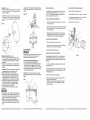
_NSTALLING THE M_TER HANDLE (FIG, A)
1. Thread the miter handle (t) into the hole (2) located
at the front of the miter table.
Locking
When transporting or storing the miter saw, the cutting
head should always be locked in the down position.
1. Push the cutting head (3) down to its lowest position.
2. Push the stop latch (2) into the locking hole (4).
IMPORTANT: To avoid damage, never carry the
miter saw by the switch handle, the cutting arm, or
the miter table handle. ALWAYS use the hand holds
in the base, or the designated carrying handle.
THE DUST COLLECTION
INSTALUNG
3
(4).
To avoid injury or possible damage to the toot, support
long work pieces by installing the extension wings to
extend the work suppor_ surface,
To avoid injury, do not connect this miter saw to the
power source until it is completely assembled and
adjusted, and you have read and understood this
Operators Manual.
SAW BLADE WRENCH (FIG. B)
t. For convenient storage and prevention of loss, there
is a slot (1) in the rear of the cutting head handle (2)
for storing the blade wrench (3) when not in use.
3. Loosen the cover plate screw (2) with a Phillips
screwdriver.
4. Rotate the cover plate (3) to expose the arbor screw
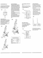
_NSTALUNG EXTENSION WINGS (F_G. E)
SYSTEN (FroG.D, D-I)
THE DUST COLLECTION
ELBOW (FIG.
5. Place the blade end wrench over the arbor screw,
Fig, F
The extension wings are provided with an end stop
bracket. The extension may be used with or without the
end stop,
To install the end stop bracket:
1. Slide the end stop (1) onto the rail (2) of the one
extension wing. Place at the desired location.
2. Thread the wing bolt (4) into the bracket and tighten.
3. Place the rods into the holes (5) provided in the miter
saw base.
4. Insert Phillips screw (6) into lab hole (7) and tighten
to hold the extension rod.
To install without the end stop bracket:
5, Loosen the wing nut and slide the end stop bracket
off the extension wing rods.
6. Install the rods into the saw base holes.
7. Insert the Phillips screw into the tab hole and tighten,
Fig. E
D)
1. install the larger end of the elbow (1) onto the
exhaust port (2).
Note: The elbow can be used to attach either the dust
bag or a vacuum hose to remove sawdust from the
work area.
6. Locate the arbor lock (5) on the motor, below the
miter saw switch handle. (Fig. G)
7. Press the arbor lock, holding it in firmly while turning
the blade wrench clockwise. The arbor lock will
engage after turning the wrench, Continue to hold
the arbor locking to keep it engaged, while turning
the wrench clockwise to loosen the arbor screw.
\
REMOVING OR _NSTALLAT_NG THE BLADE
CUTTING HEAD (FroG.C)
Raising
1. Push down slightly on the cutting handle (1).
2. Pull out the stop latch knob (2).
3. Allow the cutting head (3) to raise to the up position.
To avoid injury and damage to the saw, transport or
store the miter saw with the cutting head locked in the
down position. Never use the stop latch to hold the
cutting head in a down position for cutting operations.
mNSTALLING THE DUST BAG (FIG. D-l)
1. Squeeze the metal collar wings (1) of the dust bag (2).
2. Place the dust bag neck opening around the exhaust
port (3), and release the metal collar wings,
2
Fig= D=I
NNNtNN
1. Only use a !O-inch diameter blade,
2. To avoid injury from an accidental start, make sure
the switch is in the OFF position and plug is not
connected to the power source outlet,
REmOViNG (Fig. F,G,H)
I. Unplug the saw from the outlet.
2. Allow the miter saw to rise to the upright position.
Raise the lower blade guard (1) to the up position.
(Fig. F)
11
REMOVING
- cont'd
8. Remove the arbor screw and washer (4), outer blade
collar (6), and the blade (7). Do not remove the inner
blade collar. (Fig. H)
INSTALLING THE HOLD-DOWN CLAMP (FroG.H-!)
Place the Hold-down Clamp (1) on the desired clamp
hole (2).
Fig. H-!
NOTE: Pay attention to the pieces removed, noting
their poskion and direction they face. Wipe the blade
collars clean of any sawdust before installing the new
blade.
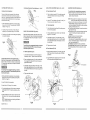
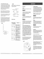
MITER SCALE (FIG. J}
Quick-Cam
Miter Table Lock Adjustment:
The miter scale on the table has nine of the most common
angle settings with positive stops at 0 ° , 15 ° , 22.5 ° , 31.6 °
and 45 ° . These positive stops position the blade at the
desired angle quickly and accurately.
1. Release Quick-cam locking lever (4).
2. Loosen Quick-Cam lock nut (5) using a 13 mm wrench.
3. Turn adjusting screw (6) either in or out until locking
lever firmly locks the miter table in place.
Positive Stop Miter Angle Adjustment:
i. Unlock the miter table, by pressing down on the positive
stop locking lever (1).
4, Tighten Quick-Cam locking nut.
2. While holding the positive stop locking lever down, grasp
the miter handle (2) and move the miter table left or right
to the desired angle.
3. Release the positive stop locking lever, making sure it
engages with the positive stop. Slight movement of the
miter handle will ensure positive stop engagement.
Miter Angle Pointer Adjustment:
I. Place the miter table at the zero position.
2
ADJUSTMENTS
2. Loosen the miter angle indicator screw (3) and adjust the
indicator to the "0" mark on the miter scale.
3. Tighten miter angle indicator screw.
4
Quick-Cam Miter Tabme Lock Operation:
INSTALLING BLADE (Fig. F, G, H)
1. lnsta{I a 10" blade, making sure the rotation arrow
on the blade matches the cloclewise rotation arrow on
the upper guard, and the blade teeth are pointing
downward.
2. Place the outer blade collar (6) on the blade and on
the arbor. Thread the arbor screw (4) into the arbor.
(Fig. H)
iMPORTANT:
make sure the flats of the blade collars
are engage d with the flats on the arbor shaft.
3. Place the blade wrench on the arbor screw.
4. Press the arbor 10ck (5), holding it in firmly while
turning the blade wrench counterclockwise. When
it engages, continue to press the arbor lock in,
while tightening the arbor screw securely. (Fig. G)
5. Rotate the cover plate (3) back until the slot in the
cover plate engages with the cover plate screw
(2). Tighten the screw with a Phillips screwdriver.
6. Lower the blade guard (1). (Fig. F)
7. Be sure the arbor lock is released so the blade
turns freely.
To avoid injury from an accidental start, make sure the
switch is in the OFF position and the plug is not
connected to the power source outlet.
Fig.J
If miter angles required are NOT one of the nine positive
stops noted above, the miter table can be locked at any
angle between these positive stops by using the Quick-Cam
table lock.
ADJUSTING FENCE SQUARENESS (Fig. I)
1. Loosen the three fence locking screws (1).
2. Using a square, lay the heel of the square against
the blade, and the rule against the fence (2) as
shown. Check to see if the fence is 90 ° to the blade.
3. Adjust the fence to be 90 ° to the blade and tighten
the two fence locking screws.
1, Unlock the miter table by pressing down on the positive
stop locking lever (1).
CAUTION: If the saw has not been used recently,
recheck blade squareness to the fence and readjust if
needed.
3. Release the positive stop locking lever.
2, While holding the positive stop locking lever down, grasp
the miter handle (2) and move the miter table left or right
to the desired angle,
4. Press down on the Quick-Cam locking lever (4) until k
locks the miter table in place.
NOTE: Quick-Cam locking lever should lock the table
and prevent it from moving. If adjustment is needed,
adjust as required.
o To avoid injury, never use the saw without thecover
plate secure in place. It keeps the arbor screw from
falling out if it accidentally loosens, and helps prevent
the spinning blade from coming off the saw.
e Make sure the collars are clean and properly
arranged. Lower the blade into the lower table and
check for any contact with the metal base or the turn
table.
!3
2
CUTTING
ARM TRAVEL
(F_G. K)
Cutting head downward travel adjustment
-
Cont'd
Fag.L
Cutting arm pivot adjustment
The up and down pivot movement or the cutting arm
should be free of side-to-side movement for accurate
miter cuts. It should be tight enough to prevent side-to-side
movement while still allowing the arm to move freely up
and down when cutting.
BEVEL STOP ADJUSTMENT
(Fig. M & N) - Cont'd
MOUNTING THE NImTERSAW (Fig. O)
90 ° Bevel indicator (Fig, N)
5.
To avoid injury from unexpected saw movement:
@ Before moving the saw, disconnect the power cord
from the outlet, and lock the cutting arm in the lower
position using the stop latch.
When the blade is exactly 90° to the table loosen the
LEFT bevel indicator screw (5) using a #2 Phillips
screwdriver.
450 Bevel indicator (FIG. N)
NOTE: The stop latch is for carrying or storing the tool. It
is NOT to be used holding the saw while cutting.
¢ Never carry the miter saw by the power cord or by the
switched handle. Carrying the tool by the power cord
could cause damage to the insulation or wire connections
resulting in electric shock or fire.
@ To avoid injury from flying debris, do not allow visitors to
stand behind the saw,
® Place the saw on a firm, level work-surface where there
is room for handling and properly supporting the
workpiece.
e Support the saw on a level work surface.
® Bolt or clamp the saw to its support.
Place the saw in the desired location, either on a work
bench or recommended leg set. The base of the saw
has three mounting holes (1).
For stationary use, fasten the saw to a workbench.
For portable use, fasten the saw to a 3/4" piece of plywood.
This mounting board can then be clamped to a secure
surface,
11. When the blade is exactly 45° to the table, loosen the
RIGHT bevel indicator screw (8) using a #2 Phillips
screwdriver.
Fig.O
6. Adjust LEFT bevel indicator (6) to the "0" mark (7) on
the bevel scale and retighten the screw.
t. Before attempting this adjustment, move the sliding
fence as far to the LEFT as possible (See "SLIDING
FENCE" on Page t9).
45 ° Bevel
2. If cutting arm (1) is too loose, turn the cutting arm
adjusting nut (2) clockwise using a 19 mm wrench.
BEVEL STOP ADJUSTMENT
3. If cutting arm is too tight, turn the cutting arm adjusting
nut counter clockwise.
7.
Unlock the bevel lock handle and tilt the cutting arm as
far to the left as possible.
8.
Using a combination square, check to see if the blade
angle is 45 ° to the table.
(Fig. M & N)
Before each cutting operation, check the position of the
blade to make sure it does not contact any metal surface.
If it contacts any metal surface, the depth of movement
can be adjusted.
If the blade is not at 45 ° to the miter table, turn the
bevel angle adjusting screw (4) in or out with a wrench
from underneath the table until the blade is at 45 ° to
the miter table.
g.
FJg.K
To avoid injury from unexpected starting or eJectrical
shock, turn the switch OFF and remove the power
cord from the power source,
90 ° Bevel adjustment
(Fig, M)
1, Loosen bevel lock handle (1) and tilt the cutting arm
completely to the left. Tighten the bevel lock handle.
Cutting head downward travel adjustment (Fig. L)
Before each cutting operation, check the position of the
blade to make sure it does not contact any metal surface.
If it contacts any metal surface, the depth of movement
can be adjusted.
2. Place a combination square (2) on the miter table with
the rule against the table and the heel of the square
against the saw blade.
10. Tighten bevel lock handle.
12. Adjust RIGHT bevel indicator (9) to the 45 ° mark (10)
on the bevel scale and retighten the screw.
i
3. If the blade is not square with the miter table, turn the
bevel angle adjusting screw (3) in or out with a wrench
from underneath the table until the blade is square with
the table.
To avoid injury from unexpected starting or electrical
shock, turn the switch OFF and remove the power cord
from the power source.
adjustment
4. Tighten bevel lock handle.
1. Before attempting this adjustment, move the sliding
fence as far to the LEFT as possible (see "SLIDING
FENCE" on Page 19).
Inch plywood
Hand
access
Stationary use
I0
2. Lower the blade as far as possible.
6
3. Loosen lock nut (3) using a 10 mm wrench.
5
4. Turn the adjusting screw (4) IN to lower the maximum
cutting depth and OUT to raise the maximum cutting
depth.
7
5. Lower the blade to the new maximum depth and rotate
the blade by hand to make sure it does not contact any
metal.
NOTE: Repeat adjustment and checking until blade no
longer contacts any metal,
(1)
FigoM
6. Tighten lock nut.
I4
Fig.N
15
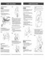
PLAN YOUR WORK
SAFETY JNSTRUCTUONS FOR BASIC
SAW OPERATION
@ Keep all guards
in place, in working order and
proper adjustment.
If any part of this miter saw is missing, bent
damaged or broken in any way, or any electrical
parts don't work, turn the saw off and unplug it.
Replace damaged, missing, or defective parts
before using the saw again.
BEFORE USING THE MINTERSAW
To avoid mistakes that could cause serious,
permanent injury, do not plug the tool in until the
following steps are completed:
@
Maintain tools with care. Keep the miter saw
clean for best and safest performance. Follow
instructions for lubricating. Don't put lubricants
on the blade while it's spinning.
€ Completely assemble and adjust saw, following
the instructions. (ASSEMBLY AND
ADJUSTMENTS)
o Learn the use and function of the ON/OFF switch,
lock-off switch, upper and lower blade guards,
stop latch, bevel lock handle, and cover plate screws.
Review and understand all safety instructions
and operating procedures in this Operator's
ManuaI.(SAFETY & OPERATIONS)
o Review the MAINTENANCE and
TROUBLESHOOTING GUIDE for your miter
saw.
O To avoid injury or possible death from electrical shock:
Make sure your fingers do not touch the plug's
metal prongs when plugging or unplugging your
miter saw. (ELECTRICAL REQUIREMENTS
AND SAFETY)
¢ Choose the correct 10 inch diameter blade for
the material and the type of cutting you plan to
do.
BEFORE EACH USE
@ Make sure the blade is sharp, undamaged
Inspect your saw.
o Disconnect the miter saw, To avoid injury from
accidental starting, unplug the saw before any
adjustments, including set-up and blade changes.
@ Compare the direction
of rotation arrow on
the guard to the direction arrow on the blade.
The blade teeth should always point downward
at the front of the saw.
o Remove adjusting
turning it on.
wrench from the tool before
e To avoid injury from jams, slips, or thrown pieces:
USE ONLY RECOMMENDED
ACCESSORIES
@ Consult
the ACCESSORIES and
ATTACHMENTS section of this Operators
Manual for recommended accessories. Follow
the instructions that come with the accessory.
The use of improper accessories may cause risk
of injury to persons.
and
properly aligned, With the saw unplugged, push
the cutting arm all the way down. Hand spin the
blade and check for clearance, Tilt the
power-head to a 45 ° bevel and repeat the check.
Any power tool can throw foreign objects into the
eyes. This can result in permanent eye damage.
Everyday eyeglasses have only impact resistant
lenses and are not safety glasses. Glasses or
goggles not in compliance with ANSl Z87.1 could
seriously injure you when they break.
@ Do not wear loose clothing, gloves, neckties or
jewelry (rings, watches). They can get caught
and draw you into moving parts.
® Wear non-slip footwear,
• Tie back tong hair.
® Roll long sleeves above the elbow.
e Noise levels vary widely. To avoid possible
hearing damage, wear ear plugs when using any
miter saw.
e For dusty operations, wear a dust mask along
with safety goggles.
Make sure there are no nails or foreign objects in the
part of the workpiece being cut,
Plan your work to avoid small pieces that may
bind, or that are too small to clamp and get a
solid grasp on,
Plan the way you will grasp the workpiece from start
to finish. Avoid awkward operations and hand
positions. A sudden slip could cause your fingers or
hand to move into the blade.
To avoid burns or other fire damage, never use the
miter saw near flammable liquids, vapors, or gases.
o Plan ahead to protect your eyes, hands, face
and ears.
® Know your miter saw.
Read and understand the Operator's Manual and
labets affixed to the tool. Learn its application and
limitations as welt as the specific potential hazards
peculiar to this tool. To avoid injury from accidental
contact with moving parts, don't do layout, assembly,
or setup work on the miter saw while any parts are
moving.
e Avoid accidental starting
Make sure the switch is OFF before plugging the
miter saw into a power outlet.
USE EXTRA CAUTION WiTH LARGE OR ODD
SHAPED WORKPmECES.
e Use extra supports (tables, sawhorses, blocks,
etc.) for workpieces large enough to tip.
O Never use another person as a substitute for a
table extension, or as an additional support for a
workpiece that is longer or wider than the basic
miter saw table, or to help feed, support, or pull
the workpiece.
¢ Do not use this saw to cut small pieces. If the
workpiece being cut would cause your hand or
fingers to be within 6-1/2 inches of the saw bfade
the workpiece is too small. Keep hands and
fingers out of the "no hands zone" area marked
on the saws table.
¢ When cutting odd shaped workpieces, plan your
work so it will not bind in the blade and cause
possible injury. Molding, for example, must lie flat
or be held by a fixture or jig that will not let it
move when cut.
e Properly support round material such as dowel
rods, or tubing, which have a tendency to roll
when cut, causing the blade to "bite".
DRESS FOR SAFETY
€ Make sure all clamps and locks are tight and
there is no excessive play in any parts.
Cluttered areas and benches invite accidents,
O Check for damaged parts. Check for:
@Alignment of moving parts
• Damaged electric cords
o Binding of moving parts
e Mounting holes
o Function of arm return spring and lower
guard:
Push the cutting arm ati the way down,
then let it rise until it stops. The lower
guard should fully close. Follow instructions
in TROUBLESHOOTING GUIDE for
o Other conditions that may affect the way
the miter saw works.
CAUTION: This machine is not designed for cutting
ferrous metals (steel, iron, and iron-based metals.)
Use this miter saw to cut only wood, wood-like
products, or soft metals like aluminum. Other material
may shatter, bind the blade, or create other dangers.
Remove all nails that may be in the workpiece to
prevent sparking that could cause a fire.
INSPECT YOUR WORKPIECE
Tighten the arbor screw,
@ Tighten the cover plate screw.
¢ Use the right tool. Don't force a tool or
attachment to do a job it was not designed to do.
Use a different tool for any workpiece that can't
be held in a solidly braced, fixed position.
e Make sure the blade and arbor collars are clean.
KEEP YOUR WORK AREA CLEAN
e Make sure there are no gaps between the
workpiece, fence and table that will let the
workpiece shift after it is cut.
e Keep the cut off piece free to move sideways
after it is cut off. Otherwise, it could get wedged
against the blade and thrown violently.
o Only the workpiece should be on the saws table.
O Secure work. Use clamps or a vise to help hold
the work when it's practical.
To avoid injury, follow all applicable safety instructions,
when cutting non-ferrous metals:
® Use only saw blades specifically recommended
for non-ferrous metal cutting.
O Do not cut metal workpieces that must be hand
held. Clamp workpieces securely.
e Cut non-ferrous metals only if you are under the
supervision of an experienced person.
WHEN
DON'T OVER-REACH
SAW
iS RUNNING
Don't allow familiarity from frequent use of your miter
saw to result in a careless mistake. A careless
fraction of a second is enough to cause a severe
injury.
Keep good footing and balance, Keep your face and
body to one side, out of the line of a possible
kickback. NEVER stand in the line of the blade,
Before cutting, if the saw makes an unfamiliar noise
or vibrates, stop immediately. Turn the saw OFF.
Unplug the saw. Do not restart u=_u_Jnu g and
correcting the problem.
Never cut freehand:
€ Brace your workpiece firmly against the fence
and table stop so it will not rock or twist during
the cut.
e Make sure there is no debris between the
workpiece and the table or fence.
17
BODYANDHANDPOSITION
(FIG.
O-!)
TURNING SAW ON (FIG. P)
SLIDaNG FENCE (FIG, Q=I)
Fig.R
Proper positioning of your body and hands when
operating the miter saw will make cutting easier and
safer. Never place hands near the cutting area. Place
hand at least 6_1/2" away from the path of the blade.
Hold workpiece firmly against the fence to prevent
movement toward the blade. Keep hands in position
until the trigger has been released and the blade has
completely stopped. Before making a cut, with the
power switch in the OFF position bring the saw blade
down to the workpiece to see the cutting path of the
blade.
¢ Keep children away. Keep all visitors a safe
distance from the miter saw. Make sure bystanders
are clear of the miter saw and workpiece.
¢ Don't force tool. It will do the job better and safer
at its designed rate. Feed the saw into the workpiece
slowly with a firm downward motion.
¢ Before freeing jammed material:
@ Turn switch OFF.
Unplug the miter saw.
¢ Wait for all moving parts to stop.
¢ After finishing a cut:
¢ Keep holding the power head down.
o Release the switch, and wait for all moving
parts to stop before moving your hands.
@ If the blade doesn't stop within 6 seconds,
unplug the saw and follow the instructions in the
TROUBLESHOOTING GUIDE section for
adjusting the blade brake before using the
saw again.
To reduce the likelihood of accidental starting, a
thumb activated lock-OFF switch is located on top of
the switch handle. The tock-QFF switch (1) must be
pushed forward before the trigger switch (2) can be
activated and the miter saw started.
Make the switch child-proof. Inse_ a padlock
through the hole (3) in the trigger switch and mock
it. This wiU prevent children and other
unauthorized users from turning the switch ON.
ROTATING HANDLE (FBG. P)
The handle of the miter saw has been designed to
rotate 45 ° or 90 ° for operator convenience. To rotate
the handle:
!. Unlock the handle locking lever (4) by pulling it
toward you.
The sliding fence must be fully extended to the left
when making any miter or beveJ cuts other than 0 ° .
Failure to fully extend the sliding fence will not al|ow
enough space for your hand which could result in
serious injury. At extreme miter or beve_ angmes the
saw bmademay a_so contact the fence.
1. Unlock the fence cam locking lever (1) by pulling it
out from the back of the fence.
BEVEL CUT (Fig. S)
When a bevel cut is required, loosen the beret lock
handle (1). Tilt the cutting head to the desired angle
as shown on the bevel scale (2). The blade can be
positioned at any angle, from a 90 ° straight cut (0 °
on the scale) to a 45 ° left bevel. Tighten the lock
handle (1) to lock the cutting head in position,
Positive stops are provided at 0 and 45 ° .
2, Fully extend the fence by sliding it out as far as
possible (2).
3. Lock the fence cam lock by pushing it IN toward the
rear of the fence.
NOTE: When transporting the saw, always secure the
sliding fence in the collapsed position (toward the saw
blade).
FigoS
2. Pull the handle locking latch (5) toward you with
your thumb.
1
3. Rotate the handle 45°or 90 ° and release the
handle locking latch.
NOTE: After releasing the handle locking latch,
rotate the handle left and right to make sure the
latch engages into the positive locking position.
COMPOUND CUT (Fig. T)
4. Lock the handle locking lever by pushing it IN
toward the back of the handle.
Note:The tightness of handle can be adjused by
following steps:
t. Loosen the four screws (6), and remove the handle
seat (7).
2. If rotating handle (8) is too loose or tight, adjusting
nut (9) clockwise or counter clockwise.
Fig.O-1
The sBiding fence must be fully extended to the Jeft
when making any compound cuts. Failure to fully
e_end the s_iding fence will not alIIow enough space
for your hand which could result in serious injury. At
extreme compound angles the saw blade may also
contact the fence.
Fig.Q-t
Fig.P
1. Fully extend the fence by sliding it out as far as
possible. See "SLIDING
FENCE" on this page.
MITER CUT (Fig. R)
1. Unlock the miter table by pressing down on the
positive stop locking lever (2).
2. Set the desired bevel angle using bevel !ock handle
(1). See "BEVEL CUT" on this page;
2. While holding the positive stop locking.lever down,
grasp the miter handle (1) ar,d move the miter table
left or right to the desired angle.
.
6 1/2"
6 I/2"
18
.........
! .......................................................
3. Set the desired miter angle using positive stop
!ocking lever (3) or Quick-Cam table lock. See
"MITER CUT" on thi: page.
Release the positive stop locking !ever, making sure
it engages the positive stop. Slight movement of the
miter handle left or right wil! ensure positive stop
engagement.
NOTE: Positive stops at provided at 0 ° , 15 ° , 22.5 ° ,
3! .6° and 45 °.
NOTE: If miter angle required is NOT one of the
positive stops noted above, the miter table can be
locked at any angle between these positive stops
by using the Quick-Cam table lock (see Page 13).
19
CUTTING BOWED MATERIAL (Fig. U)
A bowed workpiece must be positioned and cut. Do not
position workpiece incorrectly or try to cut the workpiece
without the support of the fence. This will cause the
blade to bind and could result in personal injury.
Fig=U
WORKPRECE SUPPORT (Fig. V)
Long pieces need extra support. The support should be
placed under the workpiece. Keep your hand holding the
workpiece positioned 6-1/2" or more away from the
blade. The support must let the workpiece lay flat on the
work table during the cutting operation.
NOTE: When mounted on a flat surface, the miter saw
table is 3-13/16 inches high.
AUXILARY WOOD FENCE (Fig. W)
When making multiple or repetitive cuts that result in
cut-off pieces of one inch or less, it is possibly for the
saw blade to catch the cut-off piece and throw it out of
the saw or into the blade guard and housing, possibly
causing damage or injury. To minimize this, an auxiliary
wood fence can be mounted to your saw.Holes are
provided in the saw fence to attach an auxiliary wood
fence. This fence is constructed of straight auxiliary
wood approximately 3/4 inch thick by 3 inches high by
19-1/2 inches long.
Attach the wood fence securely and make a full depth
cut to make a blade slot.
Check for interference between the wood fence and the
lower blade guard. Adjust if necessary.
NOTE: This auxiliary fence is used only with the saw
blade in the 0 ° bevel position (90 ° to the table). The
auxiliary wood fence must be removed when bevel
cutting.
CUTTING A DIMENSIONAL
4X4 WITH ONE CUT
CUTTING BASE MOLDING (FIG. Z)
Base moldings and many other moldings can be cut
on a compound miter saw. The setup of the saw
depends on molding characteristics and application,
as shown. Perform practice cuts on scrap material to
achieve best results:
1. Always make sure moldings rest firmly against
fence and table, Use hold-down or C-clamps,
whenever possible, and place tape on the area
being clamped to avoid marks.
2. Reduce splintering by taping the cut area prior to
making cut. Mark cut line directly on the tape.
3. Splintering typically happens due to wrong blade
application and thinness of the material.
(Fig. X)
A dimensional 4x4-in may be cut in half with one cut
by attaching an auxiliary wood fence of 3/4 inch thick.
See "AUXILIARY WOOD FENCE" above,
Fig,×
Auxiliary fence
Mitre saw fence
/
3-1/2" -_1
k\\
/2"
Fig.Z
i//l
t
Mitre saw table
Fig,W
FI
et
n!
c ii
VERTICAL _tlTER CUTTING (FIG. Y)
To make a miter cut in a 2x4 workpiece (1-5/8" x
3-1/2") in the vertical position on edge a spacer such
as the auxiliary wood fence described in the
" AUXIUARY WOOD FENCE"
Fig.V
slot
el'
Mitre saw table
Mitre at 45 °, bevel at 0°
.,re.,owce
_
1_5/8"-i_
f
Workpiece
3-1/2"
Mitre
saw
table
fence
Crosscut
3-1/2" x 3-1/2"
Miter 45 ° R. & L
3-!/2" x 2"
Bevel 45 ° L
2" x 3-1/2"
Compound 45 ° L.,45 ° R & L.
2" x 2"
Mitre at 0°, bevel at 45_
NOTE: Always perform a dry run cut so you can
determine if the operation being attempted is possible
before power is applied to the saw.
Auxiliary fence
capacity with auxiliary
Mitre saw table
section is required.
Fig.Y
Cutting
]I
]
3 13116"
21
CUTTINGCROWNMOLDING
(FIG,AA,
BB)
Your compound miter saw is suited for the difficult task
of cutting crown molding. To fit properly, crown molding
must be compound-mitered with extreme accuracy. The
two surfaces on a piece of crown molding that fit flat
against the ceiling and wall are at angles that, when
added together equal exactly 90 ° .
Fig.BB
Settings for standard crown molding
compound miter saw table
To avoid fire or toxic reaction, never use gasoline,
naphtha acetone, lacquer thinner or similar highly
volatile solvents to clean the miter saw.
Outside cornet
Compound
Bevel/Miter
cut crown
motdings
To avoid injury from unexpected starting or electrical
shock, unplug the power cord before working on the
saw.
Settings
KEY BEVEL
MITER
SETTING SETTING
-
DANGER
Never put lubricants on the blade while it is spinning.
\
IL
tn order to accurately cut crown molding for a 90 ° inside
or outside corrler, lay the molding with its broad back
surface flat on the saw table.
Fag.AA
MAINTENANCE
OR
Inside corner
Most crown molding has a top Fear angle (the section
that fits flat against the ceiling) of 52 ° and a bottom rear
angle (the section that fits fiat against the wail) of 38 ° .
When setting the bevel and miter angles for compound
miters, remember that the settings are interdependent;
changing one changes the other, as well. Also keep in
mind that the angles from crown molding are very easy
for these angles to shift slightly, all settings should be
tested on scrap molding.
gying flat on
For your safety, this saw is double-insulated. To avoid
electrical shock, fire or injury, use only parts identical
to those identified in the parts list. Reassemble
exactly as the original assembly to avoid electrical
shock.
TYPE OF CUT
=
Bnside corner-Left
IL
F
33.9 a
il . Positiontop of moIdingagainst
Right
fence.
2. Miter table see at RIGHT
inside corner-Right
33.9 °
31.6 ° .
1.Positionbottomof molding
Left
against fence.
2.Miter table see at LEFT 3t.6 ° .
3.LEFT side is
f.!n.!sh.e
d piece.
Outside corner-Left
Workpiece
lying flat
OL
33.9 °
31.6 °
Left
33.9 °
side
1,Positionbottomof molding
against fence,
2,Mitertable see at LEFT31,6 ° ,
&RIGHT side is finished piece.
Outside corner-Right
OR
side
3I .6 °
..........
Mitre saw table
AUTION: Do not use solvents on the guard. They
could make the plastic "cloudy" and brittle.
When cleaning the lower guard, unplug the saw from
the power source receptacle to avoid unexpected
startup.
SAWDUST
Periodically, sawdust will accumulate under the work
table and base. This could cause difficulty in the
movement of the worktable when setting up a miter
cut. Frequently blow out or vacuum up the sawdust.
side
31.6 o
3:.L.EETside is finished piece.
1R
LOWER BLADE GUARD
Do not use the saw without the lower blade guard.
The lower blade guard is attached to the saw for your
protection, Should the lower guard become damaged,
do not use the saw until the damaged guard has been
replaced, Develop a regular check to make sure the
lower guard is working properly. Clean the lower
guard of any dust or buildup with a damp cloth.
side
131.6°
l.Posiiion top of molding'"again'st
Right
2.Miter tablesee at RIGHT31.6° .
&RIGHT side is finished piece.
fence.
REPLACING CARBON BRUSHES (FIG.DD)
The carbon brushes furnished will last approximately
50 hours of running time, or 10,000 ON/OFF cycles.
Replace both carbon brushes when either has less
than 1/4" length of carbon remaining, or if the spring
or wire is damaged or burned. To inspect or replace
brushes, first unplug the saw. Then remove the black
plastic cap (1) on the side of the motor (2). Remove
the cap cautiously, because it is springloaded. Then
pull out the brush and replace. Replace,for the other
side. To reassemble reverse the procedure. The ears
on the metal end of the assembly go in the same hole
the carbon part fits into. Tighten the cap snugly, but
do not overtighten.
NOTE: To reinstall the same brushes, first make sure
the brushes go back in the way they came out. This
will avoid a break-in period that reduces motor
performance and increase wear.
Fig.DD
2
1
If blowing sawdust, wear proper eye protection to
keep debris from blowing into eyes.
LUBRICATION
All the motor bearings in this tool are lubricated with a
sufficient amount of high grade lubricant for the life of
the unit under normal operating conditions; therefore,
no further lubrication is required.
Lubrication the Following as Required:
Chop pivot: light machine oil or aerosol will penetrate
from the ends of the junction points. A qualified
service technician can remove the pivot upstop to
relieve tension, and the 2 metric set screws holding
the shaft, in order to drive the shaft about 3/4" right.
Exposed surfaces are lubricated with automotive type
oil.
Central pivotof p_astic guard: Use light household oil
(sewing machine oil) on metal-to-Vmetal or
metal-to-plastic guard contact areas as required for
smooth, quiet operation. Avoid excessive oil, to which
sawdust wil! cling,
Link: (which actuates the lower guard movement)
may be oiled at the rear pivot, greased at ball bearing
contact, and oiled where the link actuates the acety!
roller of the lower guard, if the down chop motion is
hard to start.
Toavoidinjuryfromaccidental
starting,alwaysturnswitchOFFandunplugthetoolbeforemoving,replacingthebladeor
makingadjustments.
ConsultyourSearsServiceCenterifforanyreasonthemotorwill notrun.
TROUBLESHOOTING
GUIDE
- MOTOR
PROBLEM
PROBLEM
Brake does not
stop blade within
6 seconds.
l. Motor brushes not
sealed or lightly
sticking.
2. Motor brake
overheated from use
of defective or wrong
size blade or rapid
ON/OFF cycling.
3. Arbor screw loose,
4. Other.
1, Fuse
2. Brush worn.
3. Other.
1. Fuse
2. Brush worn.
3, Other,
Motor does not
start
Brush spark
when switch
released.
TROUBLESHOOTING
GUIDE
CAUSE
- SAW
SUGGESTED
CORRECTIVE
ACTION
1. Inspect / dean / replace brushes.
MAINTENANCE
section,
2. Use a recommended
blade,
Let cool down.
3. Retighten.
4. Sears Service
Center.
1.15-Amp time delay fuse, or circuit
2, See MAINTENANCE
section.
3. Sears Service Center.
OPERATION
PROBLEM
Blade hits table.
1. Misatignment.
1. Sears Service Center.
See ADJUSTMENT
section.
Angle of cut not
accurate.
Can't adjust miter.
1. Miter table locked.
1. Squeeze miter spring Iock up.
See OPERATION Section.
2. Vacuum or blow out dust,
WEAR EYE PROTECTION.
CAUSE
SUGGESTED
under table,
CORRECTIVE
Cutting arm
wobble.
1. Loose pivot points.
1. See ADJUSTMENT
Cutting arm won't
fully raise, or
blade guard won't
fully close,
1. Part failure.
2, Pivot spring not
replaced properly
service.
1. Sears Service Center.
2. Sears Service Center.
Blade binds, jams,
burns wood.
3. Sawdust build-up.
1. Improper operation.
2. Dull blade.
3. Improper
Saw vibrates
shakes.
or
breaker.
1, None.
PROBLEM
2. Sawdust
See
ACTION
Section.
after
3, Clean and lubricate
moving
parts,
_
blade size.
4. Warped blade.
1.Saw blade not round.
2.Saw blade damaged.
3.Saw blade loose.
4.Other.
24
1, See BASIC SAW OPERATION section,
2, Replace or sharpen blade.
3, Replace with 10" diameter blade.
4. Replace blade.
1,Replace blade.
2.Replace blade.
3. Tighten arbor screw.
4.Sear Service Center.
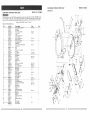
CRAFTSMAN
schematic
CRAFTSMAN
COMPOUND
MITRE
SAW
MODEL
NO.
COMPOUND
_TRE
SAW
A
137.212000
When servicing use only CRAFTSMAN replacement parts, Use of any other parts may create a HAZARD or cause
product damage, Any attempt to repair or replace electrical parts on this Miter Saw may create a HAZARD unless
repair is done by a quatified service technician Repair service is available at your nearest Sears Service Center,
Order by PART NUMBER, not by key number
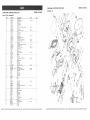
PARTS LiST FOR SCHEMATIC
Key
A
Pad: No.
Description
Size
1
2
3
2615BBDC20
12700203
12700302
HEX HD SCREW
ARM-MITER
COtE SPRING
& WASHER
4
5
6
7
8
9
10
2663MHCK16
2501MBDN85
12700604
12700707Al
12700802
2668BBDA32
12701002
CA. RE. PAN HD. SCREW
FLAT WASHER
TABLE
LOCKING
HANDLE ASS'Y
PLASTIC SLEEVE
CR. RE. PAN HD. SCREW
NEEDLE PO1NTER
M6X1
Qty
0-25
M5X0.8-10
¢ 5X'16-2
M5XO.8-10
2
1
1
4
4
1
1
1
1
1
'i"1'
...............................
_'¢'_2'_qC_:'i'_
.........................
O'R':'i_
_T_Ah"PiiS:__2€_.................................................................
i_'525;_:.'_
....................................
:_............
12
13
14
15
1270t 20_'_
12701302
2660PECK12
t 2701505
FOLLOWER
PLATE
TABLE iNSERT
OR. RE. PAN HD_ TAPPING
TILTING SCALE
16
17
t8
19
20
21
"L'22-&"_,Y=_2:
.'-'_97 _!"_,__'_
16503601
2617BBLB58
12702203
2501 NBDN40
2705FED112
BASE
SHAFT
HEX. SOC. HD. CAP
SUPPQRT
FLAT WASHER
NUT CHUCK
SCREW
SCREW
.......................................................................................................................................................
22
16505002
KNOB_HANDLE
M4XtS-10
M8X1.25-35
1/2X1-3/64
M12Xl 75 T=12
_........................................................................................................
3
!
4
l
1
1
2
1
1
1
1 ............
23
2701 FED106
HEX, NUT
M6X1.0 T=5
1
24
2601BBDA41
HE\. HD, BOLT
M6Xt .0-20
1
!
25
2574B55R02
O-RING ROD
1
26
16503401
BRACKET STOP
1
27
12703004
FENCE
2
28
2617BBLD60
HEX SOC, HD, CAP SCREW
M8X1 25-45
29
2601BDDA43
HEX, HD. BOLT
M6X1,0-30
2
30
2601BZDAD4
HEX. SOC. SET SCREW
MIOX1 5-75
1
31
2-606B,DLA32_ !i,_i t_
HEX, HD, BOLT
M5XO 8-10
1
...................................................................
32
12703503
' ...................................................................
BRACKET-TiLT
'........................................................................................................................
:1
.............
2
33
2658MZDLI36 5_ "_
DRIVE SCREW
2.3-5
1
34
1270370&%
SHAFT-PIVOT
35
2668BBDA32
CR, RE. PAN HD, SCREW
MSX0,8-t0
2
2
36
12703902
NEEDLE POINTER
I
37
12704001
FLAT WASEHR
6X 13-1
1
38
12704101
ANGLE PEGULATOR
1
39 >',ToiI_l'_O,_<-__
Z. 24i(_I-MSDN.t-1
FLAT WASHER
t 0X20-2
1
40
2705FED110
NUT CHUCK
M10X1,5 T=10
7_'...............................
2_'5:fit;1"8'6_':_
.........................
_Ck-i"_;_'i:ii_R.....................................................................................
'_O_2"(J:_
.......................................
i.............
42
43
16304201A1
2617BBLD28
LOCKING HANDLE ASS'Y
HEX,SOCKET
HD.CAP
SCREWS
44
45
46
47
2705FZD106
12704901
1270500!
12705101
NUT CHUCK
ASSIST-FENCE
BLADE HOLDER
CUSHION
t.._-%_52(_t-A4_
2617BDLC15
12705701
LOCKING HANDLE ASS'Y
HEX. SOC. HD. CAP BOLT
BRACKET
48A
49
50
_,,::_2.,_
_,_'_ z
..........................................................................................................................................................................................
5 t
12705802
SCREW
STOP
52
53
54
55A
56
12705901
17803601
2570BBN206
12706501A1
12706601
57
1270670%Z
58 __,:>%,[',,,',
EO_-;ot_ ,25g'4.N_E)N06-t 35
.,_O06
M8X1 25-25
M6X1.0
T=6
M5X0.8-16
"......................................................................
I
1
1
1
1
t
t
2
1
i .............
LOCK NUT
COMPRESSION
SPRING
E-RING
LOCKING
HANDLE ASS'Y
PIN
E-6
1
1
1
1
1
CAUTION
LABEL
FLAT WASH ER
TOOTH
WASHER
6X13-I
1
1
t
/
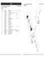
_ODEL:137.212000
CRAFTSMAN
Schematic
CRAFTSMAN
COMPOUND
Parts
schematic
iist for
MUTRE
CO_POUND
_ODEL:137,2t
SAW
MITRE
B
MODEL:137,212000
SAW
B
/
Key
5g
Part No.
18_40_
Description
WRE.CH
NEX.
Size
60
2607BBLW55
HEX, WASHER
M8X1.25-20
61
62
16930402
14930201
ARBOR
BLADE
83
!2710461
SHAFT SLEEVE
1
64
65
16510501
8595829125
TORSION
MOTOR
1
t
66
2642BZDA69
CR. RE. TRUSS
67
165'1080t
LEVER
68
69
2501MBDNO6
263686DA40
FC&T WASEHR
HD. BOLT
Qt_
1
COLLAR
/
2
1
SPRING
HD, ROUND NECK SCREW
/
-<
1
M6X1.0 14
/
Do
DO
1
1
CR. RE. COUNT
HD, SCREW
8X13-1
1
M6X1 0-15
1
cO
=;'_
..................................
i'__i%{ ......................................
_'5'L'_.................................................................................................................................................
_.......
71
165 _t 204A2
Pc_GUARD
72
16513001
CAUTION
ASS'Y
t
73
2701FRDI86
HEX NUT
74
16821601
SPRING GUARD
75
2636BBDA24
CR, RE. COUNT
76
1651D601A2
HOUSING ASS'Y
77
2660PBCK14
CR. RE. PAN HD. TAPPING
78
256888DA{37
CR. RE. PAN HD. SCREW
79
16513201
CHIP PLATE
81
26426ZDAB9
CR. RE. TRUSS
82
83
127125!;6" ZT_
2705F_kBD106
84
85
86
LABEL
1
MBX1.0 T=5
1
1
HD. SCREW
1
M4X18-16
3
M4X0 7-8
2
1
TRADE-MAR K F--AB EK
NUT CHUCK
MBX1.0 T=6
I
t
26066DLA38
HEX SOC. SET SCREW
M6X1.O-lO
2
16323204A1
16512201
BAG-DUST
SHIM
87
1651230!
ANCHOR
88
260266LA40
HEX. SOC, HD, CAP BOLT
89
127 132 _-6 ;b'_:
LABEL
t
9t
16203661
SPRING
92
2856055309
LiMiTS SWITCH
1
1
£3
2680PBCK57
CR. RE, PAN HD. TAPPING
94
12713707
HANDLE
95
12713807
BUTTON SWITC H
I
1
86
12713901
SPRING
1
97
12714t01
CLAMP-CORD
1
98
83990141
2680PBCK_.
HD. ROUND NECK SCREW
ASS'Y
RLOCK
MBXl.0-18
SCREW
1
M4X18-28
5
2
M6X1.0-25
3
MSX16.25
4
2807BSOaZ3
102
103
2£_881_DA4-2 Z_t:Z1 [_
2660PBCK20
104
16221901
SPRING WIRE
1
t05
12715207
HANDLE
1
106
t2717901
HANDLE
SEAT
1
107
12718001
RAN DLE SEAT
1
108
12718102
C LAMP HAN DLE
CABLE
1
SCREW
11t
12718401
NiA
113
2506MBN614
12718701
WAVE WASHER
SET PLATE
1
NUT CHUCK
1
1 t6
2765FBDt05
1271900_ b
t17
2660MBCE16
CR. RE. TRUSS
118
280255H506
CABLE CLAMP
t
_19
12719401
LOCK
1
120
2538MBE669
SPRING PIN
121
12719602
COMPRESSION
122
257088N20_
C-RING
123
12719801
BRACKET
124
1271990_.,2,
TILTING SCALE
1
125
126
280655545Y
16211001
LEAD WtRE ASS'Y
BUMPER
1
"_
127
t 272070q_2o
TRADE-MAR
128
2501MBDNS0
FLAT VCASHER
CUSHION
1
,,,_8.2Xl 8-2
SPR;NG PLATE
"_
1
HD, TAPPING
SCREW
MSX12-t0
1
HANDLE
1
1
STOP
1
K LABEL
l
_,,82X18
20
1
1
2
131
t 32
2
!
..Z674-QZDK_36- _C_'b_J_'_'o_
16231701A_
o
1
£PRING
129
12720901
EBLOW
"'1'3()............................................................................................................................................................................................................................................................
1_861501
EXTENSION WING
133
134
/
t
1
1t2
2668BBDA26
16961202A1
DO
t
5_'_,_r, CR, RE. PAN HD SCREW
CR.RE PAN HD. TAPPING
109
2535MN0619
PiN
"1i"0 ............................................................................................................................................................................................................................................................
12718301
BOLT
1 t5
'-.,O
d_
1
M4X18-25
181
114
\
1
CR. RE. PAN HD. SCREW
POWER
\
1
1
GUARD-CORD
%k!_
\
1
MBX!.0-14
.£g
\
1
SCREW
CR. RE. PAN HD SCREW
STOP BLOCK
MSXO 8-18
1
I
WING BOLT
V_SE ASS'Y
28
29
2800
COMPOUND
CRAFTSMAN
CRAFTSMAN
COMPOUND
Parts
schematic
list for
MITRE
MODEL:137.212000
SAW
Schematic
MITRE
MODEL:137,212000
SAW
C
C
\
MOTOR
Key
0t
02
03
04
05
06
07
08
09
10
Part No.
83965011
2571 MNC311
2641BBDA24
83965041
2001ZZ6204
2570BBN120
83965071
2570BBN 114
2004AH1010
83920172
Description
ARBOR SHAFT
PARALLEL KEY
CR.-RE ROUND HD. WASHER
BEARING COVER
BALL BEARING
C-RING
HELIX GEAR
C_RING
NEEDLE BEARING
COMPRESSION
SPRING
Size
SCREW
MSx0b-10
5
6204ZZ
A-20
A-14
HK-t010
Qty
t
t
3
1
!
1
1
t
1
t
J
\
/
/
/
2536MBE607
83965131
83966141A1
280655563Y
83990331
83750081
85968181A2
2662MZDE61
83968201
83965261
83968221
2620BBDB26
2603BBLA20
SPRING PIN
BRACKET STOP
ARMATURE
LEAD WiRE ASS'Y
BEARING BUSHING
FLOW GUIDE
FIELD ASS'Y
CR._RE.PAN HD.TAPPING
PROTECTOR WIRE
PLASTIC CAP
MOTOR HOUSING
CR.-RE.PAN HDTAPPING
HEX.-SOC SET SCREW
26A
27A
28
83990282A1
83990291A1
83990301
BRUSH HOLDER ASS'Y
RUBBER BUSHING
BRUSH COVER
M5× 12-55
SCREW
& WASHER
M5x I6-30
M5x0.8-6
1
1
1
1
t
1
1
2
t
!
I
4
2
2
2
2
\
i
_] .................................
__8___ ................................
;_fii_0_Ei_ ....................................................................................................................................
1.....
12
13
14A
15
!6
17
18A
19
20
21
22
23
24
iJ
/
/
/
\
/
30
31
\
For repair of major brand appliances in your own home...
no matter who made it, no matter who sold it!
1-800-4-_Y-HO_
Es_Aoyti_,,,
dayornight
(1-800-469-4S63)
www,
sears.cor_
To bring in products such as vacuums,
lawn equipment
for repair, call for the location of your nearest Sears Parts
1=800-488-!222
and electronics
& Repair Center.
Anytime, day or night
For the replacement parts, accessories and owner's manuals
that you need to do-it-yourself, call Sears PartsDlrectS_!
1-800-366-PART
{1-800-366-7278)
6a.m.-_ _.m.CST,
7 days a week
www.sears.cern/par_sdirect
To purchase
or inquire about a Sears Service Agreement:
1-800-827-6655
7 a.m. - 5 p.m. CST, Mon. - Sat.
Para pedir servicio de reparaci6n a domicilio,
y para ordenar piezas con entrega a domicilio:
1-888-SU-HOGAR
s,,
(1-888-784-6427)
® Regislered T_m_nark t TM Trademarkof Sears, Rc_buckand Co,
© Sears,
Rc,_buck
and Co.
® Marca Registra(ta / r_ Marcade F_ibricade Sears, Roebuck and Co.
8/200!
iiii!i;ill
!i!iii_illi
ii!i!iii_:il