1
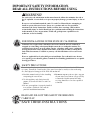
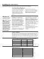
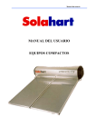
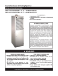
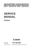
Use & Care Manual
With Installation Instructions for the Installer
Passive Solar Water
Heating Systems
The purpose of this manual is twofold: one, to
provide the installer with the basic directions
and recommendations for the proper
installation and adjustment of the water heater;
and two, for the owner–operator, to explain the
features, operation, safety precautions,
maintenance and troubleshooting of the water
heater. This manual also includes a parts list.
It is very important that all persons who are
expected to install, operate or adjust this water
heater read the instructions carefully so they
may understand how to perform these
operations. If you do not understand these
instructions or any terms within it, seek
professional advice.
Any questions regarding the operation,
maintenance, service or warranty of this water
heater should be directed to the seller from
whom it was purchased. If additional
information is required, refer to the section on
“If you need service.”
Do not destroy this manual. Please read
carefully and keep in a safe place for future
reference.
This Solar Water Heating system is for the models listed below:
RS80-42BP
RS47-21BP
!
!
Printed in Australia
Recognize this symbol as an
indication of Important Safety
Information!
California Proposition 65 Warning:
This product contains chemicals known
to the State of California to cause
cancer, birth defects or other
reproductive harm.
AP13907 (09/06)
Safety Information
Introduction . . . . . . . . . . . . 3, 4
Safety Precautions . . . . . . . 5, 6
FOR YOUR RECORDS
Write the model and serial numbers here:
Installation Instructions
#
Location . . . . . . . . . . . . . . . . . 7
#
Unit Specifications & Parts 7,8
You can find them on a label on the appliance.
Pre-Installation Review. . . . . 9
Staple sales slip or cancelled check here.
System Requirements . . . . . 10
Proof of the original purchase date is needed to obtain service
under the warranty.
Pitch Requirements. . . . . . . . 11
Roof Requirements . . . . 12, 13
Electrical Requirements. 14, 15
Typical Installation . . . . . . . . 16
READ THIS MANUAL
Plumbing Schematics. . . . . . 17
Inside you will find many helpful hints on how to use and
maintain your water heater properly. Just a little preventive
care on your part can save you a great deal of time and money
over the life of your water heater.
Details for Roof Types. . 18, 19
Frame Installation . . 20, 21, 22
Collector Installation . . . . . . 23
Tank Installation . . . . . . . . . . 24
Plumbing Installation . . . . . . 25
You’ll find many answers to common problems in the Before
You Call For Service section. If you review our chart of
Troubleshooting Tips first, you may not need to call for service
at all.
Stub Outs. . . . . . . . . . . . . . . . 26
Operating Instructions
Filling the Tank . . . . . . . . . . 26
Filling the Closed Loop . . . . 27
READ THE SAFETY INFORMATION
Your safety and the safety of others are very important. There
are many important safety messages in this manual and on
your appliance. Always read and obey all safety messages.
Test the Closed Loop . . . 27, 28
!
Connect Electric Supply . . . 29
Safety Controls . . . . . . . . . . . 30
This is the safety alert symbol. Recognize this symbol
as an indication of Important Safety Information!
This symbol alerts you to potential hazards that can
kill or hurt you and others.
Water Temperature . . . . . . . . 31
Care and Cleaning
Draining . . . . . . . . . . . . . . . . 32
Maintenance. . . . . . . . . . . . . 32
Extended Shut-Down . . . . . 33
Troubleshooting Tips
Before You Call
For Service. . . . . . . . . . . 34, 35
All safety messages will follow the safety alert symbol and
either the word “DANGER”, “WARNING”, “CAUTION” or
“NOTICE”.
These words mean:
!
DANGER
An imminently hazardous situation
that will result in death or serious
injury.
!
WARNING
A potentially hazardous situation that
could result in death or serious injury
and/or damage to property.
!
CAUTION
A potentially hazardous situation that
may result in minor or moderate
injury.
Customer Service
Frames Information . . . . 36-39
If You Need
Service . . . . . . . . . . . . . . . . . 40
2
Notice:
Attention is called to observe a
specified procedure or maintain
a specific condition.
Introduction
Thank you for purchasing a solar water heating
system. It is one of the most effective and trouble-free
systems available today. In addition to reducing your
water-heating bills, it will help preserve precious
natural resources by using free energy from the sun.
As with an electric or gas water heater, your new solar
water heating system operates automatically to ensure
you will always have an ample supply of hot water.
However, there are simple steps you can take to
increase both its efficiency and service life.
This manual provides the manufacturers recommended
procedures for Rheem Thermosiphon solar waterheating systems. The procedures are essential for
correct installation, troubleshooting and maintenance.
Read each section of this manual thoroughly before
beginning work on the system.
!
CAUTION: Changes to the design or intended
use of the Rheem Thermosiphon System will void
the manufacturers warranty. Installation,
troubleshooting, and maintenance must be
performed by a qualified technician.
This manual will help you get the most out of your
solar water heating system. Please read it carefully
when the installation is complete, and review it from
time to time to refresh your memory about the service
requirements and safety measures.
The Operation section of the manual contains
important information regarding the system procedures
as well as safety measures pertaining to the system. It
is important that you follow these guidelines to ensure
safe, efficient and trouble-free operation.
While the system requires very little maintenance,
there will be a periodic need for some upkeep. The
Maintenance section outlines those requirements for
service, which you may do yourself, as well as those
procedures best performed by a qualified service
technician.
The Troubleshooting section contains steps you can
take if the system is not performing, as it should.
The solar energy system described by this manual,
when properly installed and maintained, meets the
minimum standards established by the Solar Rating
and Certification Corporation (SRCC). This
certification does not imply endorsement or warranty
of this product by the SRCC.
The solar energy system described by this manual,
when properly installed and maintained, meets the
minimum standards established by the Florida Solar
Energy Center, in accordance with Section 377.705,
Florida Statutes. This certification does not imply
endorsement or warranty of this product by the Florida
Solar Energy Center or the state of Florida.
Your passive solar water heating system is one of the
most efficient yet simple and trouble free waterheating systems in the world.
The components of the system include a water storage
tank, solar collector panels, and a assortment of pipes
and valves.
In locations which are subject to temperatures below
41°F, a mixture of specially developed Hartgard fluid
and water circulates through the solar collector panels.
This fluid is heated by the sun, then circulated through
the jacket surrounding the water storage tank, heating
the potable (drinking) water inside the storage tank.
The Hartgard fluid is a non-toxic, food-grade liquid,
which provides freeze protection for the closed loop
heat transfer loop. It is colored blue to differentiate the
closed loop fluid from the potable water supply.
! WARNING: Under no circumstances can any
fluid other than Hartgard be used, alternate fluids
could be hazardous to your health.
This circulation of the Hartgard fluid is accomplished
naturally, without the need for pumps, sensors or any
moving parts. No moving parts mean fewer potential
problems. These solar water heaters are referred to as
closed loop systems and identified in the model
number by the last two digits.
Your how water is stored in a steel tank lined with two
coats of Primaglaze® vitreous enamel (glass) and
thickly insulated to help maintain the water
temperature throughout the day and night.
To ensure your hot water supply is never depleted, the
system is equipped with a backup heater or heating
element. On the few days a year when there may be
insufficient solar energy, you are still assured of all the
hot water you will need.
If your system is your only source of hot water, there
is one way to ensure a constant supply.
a. You can leave the breaker ON all of the time and
the heater will operate only when the water
temperature falls below the thermostat temperature
setpoint
3
Introduction continued...
While your system is one of the most efficient
available, there are two simple steps you can take to
increase your water-heating cost savings.
Keep the use of the Backup Heater to a Minimum
You can save the most money on your water-heating
bills by using the backup heater on your system as
little as possible. If the sun shines brightly between
I0 am and 3 pm, enough heat will normally be
generated to keep the water hot throughout the rest of
the day and night.
However, on days when the sky is cloudy or when
large quantities of hot water are being used, we
suggest that the backup heater be left “ON” overnight
to ensure adequate hot water the next morning.
Try to use Hot Water during Daylight Hours
When possible, schedule heavy hot water use, such as
dish washing, laundry and showers, in the middle of
the day. If hot water usage occurs while the sun is up,
the fresh (cold) water added to the storage tank is
heated more quickly.
When water is used late in the day or at night, the
fresh water entering the tank will be heated by the
4
element so hot water is available in the morning.
The Rheem Thermosiphon systems operate on the
passive thermosiphon principle a ‘closed loop’ to
provide fail-safe freeze protection up to -30°F of the
collector closed loop. The closed loop consists of the
solar absorbers, a single wall heat exchanger around
the outside of the storage tank, and plumbing
attachments.
Radiant energy from the sun heats the special longlife fluid in the solar collectors. As the fluid is heated,
it rises into the tank heat exchanger and heats the
potable water stored within.The hot potable water is
stored in a well-insulated steel storage tank, which is
lined with two coats of Primaglaze vitreous enamel
for high temperature stability.
Flow of the closed loop fluid, using the passive
thermosiphon principle, is accomplished without
pumps, sensors or moving parts.
IMPORTANT SAFETY INFORMATION.
READ ALL INSTRUCTIONS BEFORE USING.
!
DANGER!
WATER TEMPERATURE SETTING
Safety and energy conservation are factors to be considered when selecting the water
temperature setting of water heater’s thermostat. Water temperatures above 125°F can
cause severe burns or death from scalding. Be sure to read and follow the warnings
outlined on the label pictured below.
Time/Temperature Relationship in Scalds
!
DANGER
Temperature
Time To Produce a Serious Burn
120°F
125°F
130°F
135°F
140°F
145°F
150°F
155°F
More than 5 minutes
1½ to 2 minutes
About 30 seconds
About 10 seconds
Less than 5 seconds
Less than 3 seconds
About 1½ seconds
About 1 second
HOT
Table courtesy of Shriners Burn Institute
The chart shown above may be used as a guide
in determining the proper water temperature for your home.
BURN
! DANGER: Households with small children, disabled,
or elderly persons may require a 120°F or lower thermostat
setting to prevent contact with “HOT” water.
Water temperature over 125°F can
cause severe burns instantly or
death from scalds.
Children, disabled and elderly are
at highest risk of being scalded.
See instruction manual before
setting temperature at water
heater.
Feel water before bathing or
showering.
Temperature limiting valves are
available, see manual.
NOTICE: Mixing valves should be installed to reduce the
point of use water temperature by mixing hot and cold water in
branch water lines. Contact a licensed installer or the local
plumbing authority for further information.
The temperature of the water in the water heater can be regulated by setting the temperature dial of the adjustable surface mounted thermostat located behind the left tank end
cover.
1
L
3
L
4
L
RO BERTSHAW
2
L
EC O : 83
DIFF : 8
1
T
60
65 70
50 55
80
240 V a c 30A
! DANGER: Hotter water
C S6209N
4
T
To comply with safety regulations
the thermostat is factory set at
120° F or less where local codes
require.
Thermostat
Dial Pointer
75
The electrical element booster thermostat has
been factory set at 122°F (50°C) to reduce the
risk of scald injury. Adjusting the thermostat to a
higher setting is not recommended. Hotter water
increases the potential for Hot Water Scalds.
2002
EWT1L2S-203
! DANGER: Burns from Hot Water and
Steam - Use extreme care when opening relief
valves, charging closed loop, and filling storage
tank.
10MA Y
This thermostat controls the water
heater’s heating element only. (A
separate thermostat should be utilized in monitoring the temperature from the collector).
2
T
increases the potential for Hot
Water SCALDS.
5
IMPORTANT SAFETY INFORMATION.
READ ALL INSTRUCTIONS BEFORE USING.
!
WARNING!
For your safety, the information in this manual must be followed to minimize the risk of
fire or explosion, electric shock, or to prevent property damage, personal injury, or loss of
life.
Be sure to read and understand the entire Use and Care Manual before attempting to
install or operate this water heater. It may save you time and cost. Pay particular
attention to the Safety Instructions. Failure to follow these warnings could result in
serious bodily injury or death. Should you have problems understanding the instructions
in this manual, or have any questions, STOP, and get help from a qualified service
technician, or the local utility.
FOR INSTALLATIONS IN THE STATE OF CALIFORNIA
California Law requires that residential water heaters must be braced, anchored or
strapped to resist falling or horizontal displacement due to earthquake motions. For
residential water heaters up to 52 gallon capacity, a brochure with generic earthquake
bracing instructions can be obtained from: Office of the State Architect, 1102 Q Street,
Suite 5100, Sacramento, CA 95814 or you may call 916-445-8100 or ask a water heater
dealer.
However, applicable local codes shall govern installation. For residential water heaters
of a capacity greater than 52 gallons, consult the local building jurisdiction for acceptable
bracing procedures.
SAFETY PRECAUTIONS
Have the installer show you the location of the circuit breaker and how to shut it off if
necessary. Turn off the circuit breaker if the water heater has been subjected to overheating,
fire, flood, physical damage or if the ECO fails to shut off.
● Read this manual entirely before installing
or operating the water heater.
● Use this appliance only for its intended
purpose as described in this Use and Care
Manual.
● Do not attempt to repair or replace any part
of your water heater unless it is specifically
recommended in this manual. All other
servicing should be referred to a qualified
technician.
● Be sure your appliance is properly installed
in accordance with local codes and the
provided installation instructions.
READ AND FOLLOW THIS SAFETY INFORMATION
CAREFULLY.
SAVE THESE INSTRUCTIONS
6
Installing the water heater.
The location chosen for the water heater must take into consideration the following:
Local Installation Regulations
This water heater must be installed in
accordance with these instructions,
local codes, utility codes, utility
company requirements or, in the
absence of local codes, the latest
edition of the National Electrical
Code.
! WARNING: Heat
trace will not protect
against pipe freezing in
the event of power loss.
! WARNING: Extended
periods of cold weather,
including ambient air
temperatures below the
limits specified on the
right, may cause freezing
in exposed parts of the
system. It is the owner’s
responsibility to protect
the system in accordance
with these instructions if
the air temperature is
anticipated to approach
the specified limits.
It is available from some local
libraries or can be purchased from the
National Fire Protection Association,
Batterymarch park, Quincy, MA
02269 as booklet ANSI/NFPA 70.
Location
Minimum Air Temperature
Rheem Thermosiphon systems
must not be installed in areas
where the outside air temperature
can fall below 41°F continuously
for more than 18 hours. Where
outside air temperature falls lower
than 41°F Rheem closed loop
models must be installed. The
collector closed loop fluid is freeze
protected to -40°F.
If the outside air temperature is to
fall below 32°F for more than 4
hours on the Rheem closed loop
models, it is suggested that all
potable water plumbing is installed
with heat trace and insulated to
protect against pipe freezing. In the
event of a power failure, open a hot
water faucet and allow a slow
trickle of water to flow until power
is restored.
Please contact your service
technician for assistance and advice
with protection against pipe
freezing.
Inspect Shipment
Inspect the water heater for possible damage. Check the markings on the rating
plate of the water heater to be certain the power supply (Solar Electric Only)
corresponds to the water heater requirements. Make sure all parts included with
the solar water heater system are accounted for by comparing to the following
list of parts.
Water Storage Tank Specifications (Part Number RS80 & RS47)
Total Capacity ( Nominal)
48 Gallons
80 Gallons
Overall size ( L x W x H )
Nominal Working Pressure
Weight Empty
Weight Installed
Immersion Element (Booster)
59” X 20” X 20”
15 - 145 PSI.
143 lbs.
540 lbs.
2.4 kW 220/240 V
90” X 20” X 20”
15 - 145 PSI
226 lbs.
877 lbs.
2.4 kW 220/240 V
Collectors (1 or 2)
Overall Size (L x W)
Collector Model Number
Nominal Area
Weight Empty
Weight Installed
Plate-to-Plate Bonding
Test Pressure
Nominal Working Pressure
76” x 40"
RS-21BP
21.3 sq. ft.
84 lbs.
96 lbs.
Electric Welding
26 psi
-0.2 to 11.5 psi
7
Installing the water heater.
System Parts ID List
Storage Tank
Solar Collector
3/4” Union Nut
Collector Nut
18mm Union Cone
Collector Plug
8
Lag Screw
(5/16” x 1 3/4”)
(NOT INCLUDED)
3/4” T/P Valve
3/4” Check Valve
(NOT INCLUDED)
3/4” Cold Water
Expansion Valve
Fill Fitting
Collector Hot Pipe
Collector Clamps
(NOT
INCLUDED)
3/4” Tail Plug
Tempering Valve
PR6 Jacket Relief Valve
(includes “O” ring).
Collector Extrusion
3/4” Union
3/4” Tee Adapter
Collector Union
Tank Clamp
Collector Down Pipe
1 Gallon Hartgard
Collector Strap
Tank Strap
Pre-Installation
This section will guide you to gather the necessary information to install the system correctly. Use it
together with the Installation Checklist to identify all installation requirements.
These installation inspection procedures include;
• Plumbing requirements
• Review of local building codes for site
• Electrical requirements
requirements and specific guidelines for plumbing
and electrical installation.
• Roof support stress load and modification
requirements (including engineering review, if
• Inspection of installation site.
• Completion of the Pre-installation Checklist,
including customer’s signature.
Site Inspection Equipment
• Pre-Installation Inspection Checklist
necessary).
• Obtain building plans, if possible, to help locate
bearing walls and determine truss strength.
• Record extreme weather conditions on
checklist;
• Heavy-snowfall areas require roof-ridge
• Pencil or pen
mount, see Figure below.
• Ladder
• High-wind areas require an additional
• Tape measure
Bracing Kit.
• Flashlight
• Installation sites subject to winds of more
• Water pressure gauge
than 50 m.p.h. require a specially
• Pitch gauge
engineered frame.
• Compass
• Cold areas need freeze protection for all
Review Local Codes
• Review local codes and record on checklist:
domestic plumbing lines.
• Area requirements
Roof Ridge Mounts
9
Installing the water heater.
System Placement Requirements
The system must face between 135 - 225°
(Ideal direction is true South): (Refer to the
Figure on the right).
Installations outside this range require either
an additional collector or frame.
Site must be shade-free year-round and clear
of obstructions.
Area Requirements for Collectors
Plumbing/Electrical stub-out
• 1' 6" left side for roof-ridge mount,
• 1' 6" top or left side all others.
• Maintenance area: 8' on left side.
Number of
Collectors
Installation
Area Required
2
8’ x 8’
10
• All local code-required setbacks, heights, and
distances from other structures, pipe vents and
utilities must be followed.
Pitch Requirements
Correct operation requires a 15°- 45° pitch (slope). This can be done by using the roof slope itself or a
frame
! CAUTION: DO NOT
install on a roof with a pitch
beyond 45°.
Use pitch gauge and compass
and complete the following
steps. Record the results on
the checklist.
• Record pitch and compass
bearing of proposed
installation site.
• Using table shown below,
select number of collectors
and correct type of
installation.
Frame Installations
Roof Installations
NOTICE: A roof pitch
beyond 30° requires
additional bracing.
NOTICE: A crane may be
necessary for installation.
Compass
Bearing
Pitch
Mount
No. of Collectors
135° - 225°
14° - 45°
None
2
135° - 225°
0° - 15°
Frame
2
226° - 270°*
15° - 45°
None
2
5° - 134°
270° - 315°
15° - 45°
Side Pitch
2
0° - 44°
316° - 360°
15° - 35°
Reverse Pitch
2
* If installed in this orientation,solar heater will not provide maximum
solar heating capacity.
11
Installing the water heater.
Roof Survey
NOTICE: A roof in poor
condition may need
replacement before the
system is installed.
Record the following on the
checklist:
• The type of roofing material (tile,
shingle, tar & gravel, metal, etc.).
• The condition of the roof. Note
any repair requirements
needed prior to installation.
• Draw diagram (top view) as
shown below, of installation area.
Mark location of the system and
stub-out.
• Using the table below, select the
appropriate supporting structure
for your solar system.
Roof Type
Installation Type
Supporting Structures
All types except sturdy tiles and
metal
With pitch (standard)
4 runners and Collector Extrusion
Sturdy tiles or metal roof with
No obstruction of water flow
With pitch (metal / sturdy tile)
Collector Extrusion only
All types
Side pitch
2 runners + Frame
All types
Reverse pitch
2 runners + Frame
All types
Flat / shallow pitch
2 runners + Frame
Roof Support Requirements
The system weighs up to 1089 lbs (80 Gallon
System) when installed and filled. It may not be
necessary to provide additional support but you must
inspect the roof support system to determine if
additional bracing is needed.
Record the following on the checklist.
! CAUTION: If the following modifications do
not apply to the installation site, an engineer must
specify support modifications.
Conventional Roof Modifications;
• Locate the load bearing wall beneath installation
site (refer to building plan if available) and
indicate on the roof-site plan. If a load-bearing
wall is not available, note this on the checklist.
• Review Figure at the top of the following page
and select correct supports.
12
Conventional Roof Modifications
Truss Frame Modifications
Determine the correct truss frame modification using the figures shown below.
Allowable Spans for Trusses
2” x 4” Top Chord 2” x 6” Top Chord
24” O.C. Kickers
Bottom Chord
Pitch
Roof Material
21”
32”
X
2”x4” or 2”x6”
3:12¹
Tile
24”
36”
X
2”x4” or 2”x6”
3:12¹
Shake
25”
38”
X
2”x4” or 2”x6”
4:12²
Tile
28”
42“
X
2”x4” or 2”x6”
4:12²
Shake
28”
36”
X
2”x4” or 2”x6”
7:12³
Tile
X
30”
38”
2”x4” or 2”x6”
NOTICE: For truss spans >36”, use double 2” x 6” kicker.
7:12³
Shake
¹ Pitch of 3:12 or less
² Pitch of 4:12 to 6:12
³ Pitch of 7:12 or greater
13
Installing the water heater.
Review the checklist for installation requirements.
Check the following before beginning installation.
Permits
Obtain required permits before installation.
Work Force
An 80 gallon storage tank weighs up to 242 lbs
empty, requiring a crew of two or more to install.
Inventory
Review Section on Frames, included hardware, and
all optional supplies before beginning installation.
Required Tools, Equipment and Supplies
Basic Plumbing, Electrical and Carpentry Supplies
• Metric wrench (36 mm open end wrench)
• 12” pipe wrench
• Two 12” adjustable (crescent)
• Wrenches
• Water pressure gauge
• Crowbar
• Copper tubing cutter
• Soldering kit
• Caulking gun
• 24” Spirit (bubble) level
• Cable cutter / stripper
• 6” diagonal cutting and long nose pliers
• 100' Grounded extension cord
• Screwdriver Set (# 2 Philip’s, 1/4” Slotted)
• Tape measure (100 Foot)
• 16-Ounce claw hammer
• Marking pen
• Utility knife
• 3/8”-drive socket set
• 2 Extension ladders
• Flashlight / electric lantern
• Pipe vice / cutter / threader
• Volt, ohm, ammeter
• Hacksaw
• 1/2” Electric drill with bit set
• Skill Saw with standard and masonry blades
• Crane, if required
• 1” Wood-boring bit
Consumable Supplies:
• Masking/duct tape
• Wood/sheet metal screws
• Dielectric pipe unions
• Waterproof sealing compound
• 5/16” Lag Screws, 1 3/4”, 2”, 3”, 6”, as required
• Washers
• Nails, 16g, or assorted, as required
• Silicone sealant
• 2' x 4' x 8'4” redwood, treated-wood or
• Unistrut runners, as required
Customer Approval
• Review the checklist with the customer
and discuss all installation
requirements and procedures.
• Ask the customer to sign the checklist.
NOTICE: This guide recommends minimum branch circuit sizing and wire size based on National Electric Code.
Refer to the wiring diagrams in this manual for field wiring connections.
Branch Circuit Sizing and Wire Size Guide
Total Water
Heater Wattage
3,000 or lower
4,000
4,500
14
Recommended Over Current Protection
(fuse or circuit breaker amperage rating)
208V
20
25
30
240V
20
25
25
277V
15
20
25
480V
15
15
15
Copper Wire Size AWG Based
on N.E.C. Table 310-16 (75°C)
208V
12
10
10
240V
12
10
10
277V
14
12
10
480V
14
14
14
Electrical System Requirements
NOTICE:All wiring must conform to local codes
or the latest edition of National Electrical Code
ANSI/NFPA 70.
! WARNING: Any wiring outside of the house
should be rated for the appropriate weather
conditions.
If the system is being used as a pre-heater to an
existing water heater, the electrical review and
installation may not be required.
A 240 Volt electrical breaker with appropriate amp
rating is required to activate the Backup Heating
Element located near or as part of the main circuit
breaker/fuse panel.
The manufacturer’s warranty does not cover any
damage or defect caused by installation, attachment or
use of any type of energy saving or other unapproved
devices (other than those authorized by the
manufacturer) into, onto or in conjunction with the
water heater. The use of unauthorized energy saving
devices may shorten the life of the water heater and
may endanger life and property.
The manufacturer disclaims any responsibility for
such loss or injury resulting from the use of such
unauthorized devices.
Check the availability of a 240-volt, and an
appropriately sized electrical breaker. A separate
branch circuit with copper conductors, overcurrent
protective device and suitable disconnecting means
must be provided by a qualified electrician. If the
breaker is not available, mark a location for a separate
breaker.
When replacing an existing electric water heater see
the chart on page 14.
The voltage requirements and wattage load for the
water heater are specified on the rating plate on the
front of the water heater.
The branch circuit wiring should include either:
• Metallic conduit or metallic sheathed cable
approved for use as a grounding conductor and
installed with fittings approved for the purpose.
• Non-metallic sheathed cable, metallic conduit or
metallic sheathed cable not approved for use as a
ground conductor shall include a separate conductor
for grounding. It should be attached to the ground
terminals of the water heater and the electrical
distribution box.
Electrical Schematic
Weatherproofed
Roof-Mounted 2-Pole,
20-Amp Rated Switch Disconnected
Hot Return to
House
Auxiliary Thermostatically Controlled
Electric Back-Up 220/240 Volt/2.4 kW
Weatherproofed
Roof-Mounted 2-Pole,
20-Amp Rated Switch
Disconnected
Roof Line
Tank-Mounted
Thermostat 220/240
Volt D.P.S.T.
Cold Supply to Water
Heater
Circuit Breaker
Old Water Heater
Electrical Junction Box
Main Supply Panel
240 Volt, 20 AMP Supply Breaker Using No.
12 Wire (Copper) Minimum See the table on
page 14 for additional information.
240 Volt, With Ground Supply
Using 12 Ga.Wire (Copper)
Minimum Depending on Amp
draw. - See the table on page 14
for additional information.
15
Installing the water heater.
A new combination temperature and pressure relief valve, complying with the Standard for Relief Valves
and Automatic Gas Shut-Off Devices for Hot Water Supply Systems, ANSI Z21.22, is supplied and must
be installed in the opening provided and marked for the purpose on the water heater. No valve of any
type should be installed between the relief valve and the tank. Local codes shall govern the installation of
relief valves.
Typical Installation
! WARNING:
Burns from
Collector Fluid or
Downpipe and Hot
Pipe - Cover the
solar collectors with
an opaque (no light
can penetrate)
material and allow
plumbing and fluid
to cool before
attempting any
maintenance.
Storage Tank
Collectors
T&P Valve
Jacket Relief Valve
Collector Down Pipe
Tee
Adapter
Tempering
Valve
Cold Water
Expansion
Valve
Collector
Hot Pipe
Type of Installation
! WARNING: Heat
trace will not protect
against pipe freezing in
the event of power loss.
NOTICE: The closed
loop piping between the
storage tank and solar
collectors does not
require insulation and is
rated up to 30°F.
16
Choose the installation type from the
following;
1. As a replacement for an existing
water heater (Preferred).
2. As the stand alone source of hot
water for new construction or
locations without a previous water
heater.
3. As a pre-heater to an existing water
heater.
NOTICE: Using the system as a pre
heater to an electric water heater is
less efficient than a stand alone
system. (Not Recommended). Do not
perform this installation unless
specifically requested by the customer.
All plumbing installation must conform
to local codes.
All piping must be adequately
supported; supports must conform to
local codes.
All piping must be sloped to a drain.
Plumbing must be installed so that the
performance of any fire rated assembly
is not reduced.
Plumbing System Schematic for Replacement of Existing Electric Water Heater
T/P
3/4”
Tank
3/4”
Collector
Collector
Valve Settings:
Solar Only = (TWV1-1) + (TWV2-1) + (Pre Heat OFF)
Storage Only = (TWV1-2) + (TWV2-2) + (Pre Heat OFF)
Solar Pre Heat = (TWV1-1) + (TWV2-2) + (Pre Heat ON)
TWV1 = Two Way Valve - 1 Inlet Selector
TWV2 = Two Way Valve - 1 Outlet Selector
Pre Heat = Solar Pre Heat Valve
M = Mixing Valve
T/P = Temperature & Pressure Relief
Plumbing System Schematic for Installation of stand alone Water Heater
T/P
Tank
3/4”
3/4”
Collector
Collector
M = Mixing Valve
T/P = Temperature & Pressure Relief
17
Installing the water heater.
Plumbing System Schematic for Installation as Pre Heater
T/P
3/4”
3/4”
Collector
Collector
Notice: All pipe work 3/4” unless
otherwise stated.
Valve Settings:
Solar Only = (TWV1-1) + (TWV2-1) + (Pre Heat OFF)
Storage Only = (TWV1-2) + (TWV2-2) + (Pre Heat OFF)
Solar Pre Heat = (TWV1-1) + (TWV2-2) + (Pre Heat ON)
TWV1 = Two Way Valve - 1 Inlet Selector
TWV2 = Two Way Valve - 1 Outlet Selector
Pre Heat = Solar Pre Heat Valve
M = Mixing Valve
T/P = Temperature & Pressure Relief
Types of Roof Installation
This section contains instructions for correct installation of the system. Complete the procedures in the
order listed.
Installation types are divided into the Frame Installation
following:
(Side, Reverse, Shallow-Pitch and
NOTICE: Installation
Flat-Roof Installation)
of roof supports,
Standard Installation:
The system is mounted on a variable
plumbing, and
The
system
is
mounted
to
wood
or
electrical components
pitch frame to provide pitch or a fixed
Unistrut runners directly to the roof
must conform to local
pitch frame to provide directional
with no need for pitch or directional
codes.
changes.
changes.
Metal / Sturdy Tile Installation:
The system is mounted directly to the
roof with no need for pitch or
directional changes.
18
Roof Preparation
This section contains instructions for correct installation of the system. Complete the procedures in the order
listed.
NOTICE: The
storage tank will be
parallel to rafters
of trusses for sidepitch mount and at
a right angle for all
other mounts.
Refer to the checklist for necessary roof
modifications on page 12.
clearance on each side (refer to Figure
below) set aside for reinstallation.
Install supports for Fragile Tile Roof
Install waterproof material over cleared
area.
The system may be installed directly on
most roof types if the roof is in good
condition with adequate drainage.
For other types of roofs, do the following:
Fully seal and waterproof new material.
Continue with section; Supporting
Structure Installation.
Clear area of roofing material from top of
roof to lower edge of roof with 2'
NOTICE:
Supporting rafters
may be either 16” or
24” on center.
Runners will not be
equally spaced on
16” on-center
rafters. See Figure
for “Wood Runner
Detail”.
NOTICE: Double
check the placement
of the runners over
the rafters or trusses
before drilling holes.
Fragile Tile Roof
Supporting Structure installation
Refer to the appropriate section listed
below for installation procedures:
•Standard Installation: Page 19
•Metal / Sturdy Tile Installation: Page 20
•Frame Installation: Page 21
NOTICE: You
may want to predrill runners with
pilot holes to avoid
splitting runners
with lag screws.
Standard Installation
1. Mark supporting rafter/truss and
bearing-wall locations on roof.
2. Place four 2" x 4" x 8' 4” redwood,
treated-wood or Unistrut runners
parallel down roof slope over marked
rafters or trusses.
runner ends and attach to rafters or
trusses with 5/6" x 6" lag screws and
washers.
4. Flash and seal all roof penetrations.
5. Position Collector Extrusion so that flat
vertical edge is toward roof ridge
6. Level the Extrusion using a spirit level
and shims After leveling, raise the hot
pipe side of the extrusion by 1/2” per
collector to ensure correct operation of
the system (eg. For a 2 collector
system, raise the hot pipe side of the
extrusion by 1”).
•For standard installation, runners must be
placed within 3’ of roof ridge
7. Mount the Extrusion to each runner
using 5/16" x 2” lag screws or Unistrut
bolts.
•For roof-ridge mounts, place top of
runners at roof ridge
8. Continue with Collector Installation,
page 23.
3. Drill each runner in center and 6" from
19
Installing the water heater.
Wood Runner Detail for 16” & 24” On-Center Rafters for Standard Installation
Collector Extrusion Detail for Standard Installation
! CAUTION: The
Extrusion must slope
1/2” per collector
from horizontal (hot
pipe side to be higher)
for the system to work
correctly.
Metal or Tile Installation
NOTICE: Be sure the
flat side of the vertical
support of the extrusion
faces toward the
collector location and
the “U” shape opens
toward the lower roof
edge.
20
1. Mark tank location on roof with
front foot of tank located directly
over reinforced roof area.
2. Measure 82 inches down roof
from front foot of tank to
determine location for Collector
Extrusion.
3. For Tiled roofs, remove tiles to
allow for room to screw collector
straps to rafters or trusses. If
installing three collectors, remove
tiles for third collector strap.
4. Slide the Collector Extrusion on
to the Collector Straps. After
leveling, raise the hot pipe side of
the extrusion by 1/2” per
collector to ensure correct
operation of the system (eg. For a
2 collector system, raise the hot
pipe side of the extrusion by 1”).
6. Attach straps onto rafters or
trusses with 5/16” x 6" lag
screws.
7. Replace tiles that have previously
been removed.
8. Flash and seal all roof
penetrations.
9. Continue with Collector
Installation.
Collector Extrusion & Strap Installation Detail - Tile Roof
! CAUTION: Straps must
be attached directly onto the
rafters or trussed not less
than 39” apart and not more
than 63" apart.
! CAUTION: The
Extrusion must slope 1/2”
per collector from horizontal
(hot pipe side to be higher)
for the system to work
correctly.
Collector Extrusion and Strap Installation Detail - Metal Roof
! CAUTION: Ensure the
weatherproof seal is
restored.
Frame Installation
The frame is attached to two wood or
Unistrut runners and installed over rafters or
trusses, bearing wall or reinforced roof area.
frame installations, the
tank-end support points Fixed pitch frame assemblies are used in
must be located over the reverse and side pitch installations, whereas
load-bearing wall or a
variable pitch frame assemblies are used for
reinforced roof area.
shallow pitch or flat roof installations.
! CAUTION: For all
! CAUTION: Ensure
the weatherproof seal is
restored.
1. Remove roofing if necessary where runners
will be installed to provide solid base for
the frame.
2. Install two off 2" x 4" x 8'4” redwood,
treated-wood or Unistrut runners;
• Mark supporting rafter or truss locations,
• Place tank-end of runners over load-bearing
wall,
• Cut runners to straddle the two closest
rafters diagonally,
• Angle runners under support points to
permit rainwater drainage.
21
Installing the water heater.
Frame Installation continued....
NOTICE: Allow
room for “U” bracket
pipe leg cradle on
frame. Roofs with
steep pitches (above
20°) may require
short pipe legs at
collector end of frame
for clearance.
• Drill each runner in center and 6" from
runner ends and screw to rafters or
trusses with 5/16" x 6" lag screws and
washers,
• Flash and seal all roof penetrations.
3. Move all pieces of Frame to roof and
assemble (refer to Figure below).
• Attach 'U' brackets to runners with
5/16" X 1 3/4" lag screws and washers
or Unistrut bolts (refer to Figure
below),
Lower Pipe Leg Installation
4. Attach Frame to runners:
• Insert un-drilled ends of pipe legs into
frame,
For shallow-pitch or flat roofs, screw
frame directly to runners.
• Attach drilled end of pipe legs to 'U'
brackets using 2" screws,
For side pitch or reverse pitch roofs;
• Screw pipe legs to frame with 2"
screws through pipe legs and frame
sleeves,
• Loosely screw collector end of frame to
runners with 5/16" x 1 3/4" lag screws
and washers,
• Level frame and measure the required
length for the tank-end pipe legs ( 5),
• Measure and cut un-drilled end of pipe
Frame Assembly
Pipe Leg Connection Detail
2”
Screws
Frame
Leg
“U”
Bracket
22
legs to correct length,
•Continue with Collector Installation.
Collector Installation
Collector Fitting Installation Detail
Collector Union
! CAUTION: The
Extrusion must slope
1/2” per collector
from horizontal (hot
pipe side to be higher)
for the system to work
correctly.
Collector
Plug
Collector Nut
Fill
Assembly
! CAUTION: Do
not damage Internal
Collector Absorber
with screws.
Collector
Nut
Collector Union
1. Set collectors in place, resting lower
ends on collector extrusion or frame,
2. Remove plugs from corners of the
collectors
3. Connect collectors with collector
unions. Do not tighten fully (refer to
points A & B in the figure above).
4. Check that collectors slope 1/2” per
collector from horizontal (hot pipe
side to be higher).
6. Install the collector plug and the
collector nut at Point C.
7. Install collector fill assembly and
collector nut at Point D.
8. Attach collectors to support
structure as shown below.
Standard Installation
Attach collectors to extrusion using
2 sets of collector clamps, screws and
nuts, per collector .
Frame Installation
1. Attach collectors with 2 sheet metal
screws per collector, through the
angle iron upright into the collector
frame at the top and bottom of each
collector.
2. Tighten collector unions, parts and
hardware securely.
3. Continue with storage tank
installation.
Collector Attachment Details:
Standard, Metal, or Tile.
Collector Attachment Details:
Frame Installation
23
Installing the water heater.
Storage Tank Installation
! CAUTION:
Do not damage
internal collector
absorber with
screws.
! CAUTION:
DO NOT install
on a roof with a
pitch beyond
45°.
Collector down
pipe alignment
Tank Clamp
Collector
Hot Pipe
! CAUTION:
If lifting tank to
roof manually,
use correct
lifting
techniques.
NOTICE: A
crane may be
necessary for
installation.
1. Spread open (4) four tank clamps (2 for
metal or sturdy tile installations) to allow
room to clear tank foot, and attach to
rear foot of tank.
2. Place the (2) two tank-to-collector
spacers at the top of the collectors, to
ensure correct spacing for alignment of
downpipe and hot pipe. Refer to figure
above.
! CAUTION:
If pitch is 30°45°, additional
tank bracing is
required.
! CAUTION: Do not tighten tank in place
at this stage.
Tank End
directly into rafters or trusses not less than
39” apart and not more than 63” apart.
Tank End
Storage Tank Attachment Detail to Metal/Tile
2. Attach two tank straps directly to rafters
or trusses with 5/16" x 1 1/4" lag screws.
3. Screw tank clamps to each strap with
5/16" X 1 1/2" machine screws and
washers.
Frame Installation
Storage Tank Attachment Detail to Wood Runner
3. Attach tank to supporting structure as
detailed in sections above.
Standard Installation
Drill holes in each runner, and screw
clamps directly to runner with 5/16" X
1-1/4" lag screws, see figure above.
Metal / Sturdy-Tile
1. For a sturdy tile roof, remove the tiles to
allow room to screw tank straps directly
into the rafters or trusses.
24
! CAUTION: Tank straps must be screwed
1. Screw tank clamps directly to frame with
5/16" X 1 1/2" machine screws and
washers.
2. Carefully align collector hot pipe and
downpipe connections with tank.
3. Connect hot pipe to lower-left side of
tank (or pipe extension) and upper-left
side of left-hand collector. Do not fully
tighten.
4. Connect downpipe to lower-right side of
tank (or pipe extension) and lower-right
side of right-hand collector. Do not fully
tighten.
5. Tighten hot pipe and downpipe
connections side of right-hand collector.
Do not fully tighten.
6. Level the tank.
! CAUTION: If
using teflon tape to seal
T&P valve, make sure
the tape does not block
the water passage.
7. Tighten the tank system in place.
Tee
Adapter
8. Tighten hot pipe and downpipe
connections.
9. Install tee adapter (See figure at
right).
T&P
Valve
10. Install T/P Valve into tee adaptor
(See figure at right).
Tail
Plug
Downpipe
Connection
11. Install tail plug in right end of tank
(See figure at left).
11. Continue with plumbing
installation as described in section
below.
For collector connections see
specific installation diagram
for each model.
Storage Tank Plumbing Attachment
Detail, Left Side
Plumbing Installation
! CAUTION:
Plumbing must be
installed so that the
performance of any
fire rated assembly
is not reduced.
NOTICE: The
location of the roof
jack may vary
depending on
installation type.
NOTICE: The
closed loop piping
between the storage
tank and solar
collectors does not
require insulation.
WARNING:
Heat trace will not
protect against
pipe freezing in the
event of power loss.
1. Review checklist sketches for roofjack location.
install optional Pressure Regulator on
main supply to building.
2. Mark on the roof the exact location
of roof-jack installation.
• Connect the outlet of the T/P and
pressure relief valve to a suitable open
drain so that the discharge water
cannot contact live electrical parts and
to eliminate potential water damage.
3. Install plumbing according to type of
installation on page 17 & 18 and
plumb lines to roof according to Key
to Stub-Outs.
External Piping Insulation
• Where potable water piping is in an
external location or attic space where
the temperature can be as low as 19°F
it must be insulated with a minimum
¾” Armaflex (or similar) flexible
elastomeric closed cell thermal
insulation. Where the temperature can
fall to 12°F the insulation thickness
must be increased to 1 ½”.
• It is recommended that electrical heat
tracing be installed on potable water
piping in areas where the temperature
falls below 32°F for more than 4 hours
with no hot water draw to protect
against pipe freezing.
• Insulation in external locations can
deteriorate through UV radiation. To
prevent this, a layer of outdoor UV
stable paint or other similar protective
coating must be applied to the
insulation.
! DANGER: Hotter water increases the
potential for Hot Water SCALDS.
• Piping used should be of a type
approved for hot water distribution.
• The discharge line must not be smaller
than the outlet of the valve and must
pitch downward from the valve to
allow complete drainage (by gravity)
of the relief valve and discharge line.
• The end of the discharge line should
not be threaded or concealed, and
should be protected from freezing.
• No valve of any type, restriction or
reducer coupling should be installed in
the discharge line.
NOTICE:
1. All plumbing installation must
conform to local codes.
2. All piping must be adequately
supported, supports must conform
to local codes.
The following may be performed in any
order necessary:
3. All piping must be adequately
insulated, insulation must conform
to local codes.
• If water pressure exceeds 60 psi,
4. All piping must slope to drain.
25
Installing the water heater.
See Key to Stub - Out Details Below:
NOTICE: This
section does not apply
if this system is
installed as a preheater to an existing
water heater.
! CAUTION: Do
not connect the
electricity to the main
circuit breaker until
the tank is full of
water.
NOTICE: Ensure the
plumbing is installed
to allow for the
removal of the
storage tank end
cover for the
maintenance
procedures.
All plumbing and wiring Stub-Outs to
be a minimum of 18" above roof frame.
(E) Electrical service (240V, 20-amp
required only if using auxiliary
electrical backup in tank)
• Install hot and a cold water shut-off
valves next to the existing water
heater in a convenient location.
Electrical Installation
1. See “Connect the Storage Tank to
the Electrical Supply Section” on
page 29 for electrical requirements.
2. Install according to Figures on page
15, electrical schematic, and optional
electrical connections.
Install Roof - Jack Panel
1. Remove the necessary roofing
material,
(R) 3/4" Relief Line
2. Place the panel over the plumbing
and electrical stub-outs and install it
with nails or screws,
(H) Hot Supply to House
3. Flash and seal all roof penetrations.
(C) 3/4" Cold Supply to Rheem
thermosiphon tank
4. Replace the roofing material.
• NOTICE: Mixing valves should be
installed to reduce the point of use
water temperature by mixing hot and
cold water in branch water lines.
Contact a licensed installer or the local
plumbing authority for further
information.
Connect the Plumbing to the Storage
Tank, (see the Figure at the top of
page 25.)
1. Connect the cold water supply line to
the storage tank.
2. Connect the solar hot water line to
the Tee Adapter.
3. Connect the drain line to T/P Valve.
To Fill the Water Heater
! CAUTION: On
new construction,
Do Not fill storage
tank and/or charge
the closed loop
system until the
water heater is
ready for use.
Cover the collectors
until the system is
filled and charged.
Place a tag on the
system if it s not
filled and charged.
26
Make certain the drain valve is
completely closed.
Open the shut-off valve in the cold water
supply line.
faucet(s) indicates a full water heater.
Check the tank and cold water lines for
leaks and repair any found.
Open each hot water faucet slowly to
allow the air to vent from the water
heater and piping.
Ensure that the storage tank is completely
free of air by opening the T/P Valve until
it discharges a steady stream of water.
Then close the valve.
As the water heater fills, air will be
pushed from the open outlet faucet. A
steady flow of water from the hot water
The system is now ready to Test and Fill
the closed loop as described in the next
section of this manual.
Test and Fill the Closed Loop
! WARNING:
Under no
circumstances can
any fluid other
than Hartgard be
used, alternate
fluids could be
hazardous to your
health.
Closed Loop Fluid The closed loop must
be filled ONLY with Hartgard solution
and potable water.
Fluid Color
Each system closed loop is to be filled
with one bottle of Hartgard and the
balance potable water.
• Eye Contact: Irrigate with water for 5
minutes
When mixed, the approximate Hartgard
concentration is 20%.
Light Blue
First Aid
• Skin Contact: Wash with flowing water
or shower
• Inhalation: No adverse effects
Material Safety Data
• Ingestion: No adverse effects
Service Temperature Range
-40°F to 300°F
Freezing Point -50°F
• Advice to Doctor: Treatment based on
judgement of doctor in response to
patient reaction
Boiling Point
212°F
Disposal of Fluid
Flash Point
218°F
Reprocess or burn in an approved
incinerator in accordance with
Federal/State/Local code requirements.
Auto Ignition Temperature
> 750°F
Test and Fill Procedure
! CAUTION: On
new construction,
Do Not fill storage
tank and/or charge
the closed loop
system until the
water heater is
ready for use.
Cover the collectors
until the system is
filled and charged.
Place a tag on the
system if it s not
filled and charged.
• Remove the Fill Plug from the collector
fill assembly.
• Remove PR6
Jacket Relief Valve
from the tank.
• Connect a 1/2”
hose and fill the
closed loop with
water.
• Continue filling
until the water
overflows from the
PR6 Jacket Relief
Valve port and air
bubbles stop.
• Fit the Test Block
into the PR6 Port.
• Fit the PR6 Jacket
Relief Valve onto
the Test Block.
• Now remove the
hose from the Fill
Assembly and
replace the Fill
Plug.
• Connect a bicycle
pump to the Test
Block and
pressurize the
Closed Loop to
11.6 psi.
• Check all
connections for any
evidence of leakage.
• Ensure that the
pressure remains
constant at 11.6 psi
for at least 10
minutes.
27
Installing the water heater.
• Rectify leakage if
observed at any of the
connections and repeat
steps indicated on
previous page.
• Release the pressure
from the closed loop
by loosening the
PR6 valve from the
Test Block.
• When the pressure is
zero, tighten the
PR6 Jacket Relief Valve.
• Once again remove
the Fill Plug from the
Fill Assembly and
connect the hose.
• Remove the PR6
Jacket Relief Valve
and siphon the entire
contents of the blue
Hartgard container
with help of the hose.
• Water will flow
through the PR6
port on the Test
Block during this
operation.
• When the Hartgard
container is
completely empty,
refit the PR6 valve
onto the Test Block.
28
• Remove the hose from
the Fill Assembly.
• Allow the fluid to flow
until it stops.
• (This checks the
vacuum seal on the
PR6 valve).
• Once the flow stops,
screw in the Fill Plug.
• Pressurize the Closed
Loop to 11.6 psi as
before with the help of
the bicycle pump and
ensure there is no leak
at the Fill Assembly.
• Ensure that the pressure
remains at 11.6 psi for
at least 10 minutes, as
before.
• Release the pressure
from the closed loop
by removing the PR6
Valve from the Test
Block.
• Remove the Test
Block from the Tank.
• Fit the PR6 Valve in
its place on the tank
after ensuring that the
“O” ring is in its seat.
Connect Storage Tank to Electrical Supply
! CAUTION:
To reduce the
risk of electric
shock or fire
follow local
codes.
! CAUTION:
Ensure the water
heater tank is
full of water
before the main
is turned on.
• Use only a utility supply having a
maximum of 240 volt, 1 phase, 60Hz,
power supply.
1. Turn OFF the main site electrical
power.
WARNING: Turn off all power to
avoid injury.
2. Remove left tank End Cover,
thermostat and element covers, to
expose electrical connections.
• The water heater must always be
connected to the ground in
accordance with the local codes.
3. Connect the hot and neutral
electrical connections into the
terminal block.
• Connect the branch circuit
equipment grounding means and
system grounding conductors to the
water heater at the terminal marked
“G”.
4. Connect the electrical ground wire to
the ground screw
5. Replace tank end cover.
6. Turn ON main circuit breaker.
• Use only copper conductors.
Detail of Electrical Connections
Neutral
To
Element
Hot
Thermostat
Ground
Element
Anode
Complete System Installation
1. Insulate all plumbing lines. See page
16 for details
4. Instruct homeowner regarding
system operation and features.
5. Complete Post-Installation Checklist.
2. Replace tiles or other roofing to
cover straps, etc, as necessary.
3. Remove and dispose of packing
materials and leave area clean and
neat.
29
Operating the water heater. Installation Checklist
CAUTION: Hydrogen gas can be produced in a hot water system served by this water heater that has not been
used for a long period of time (generally two weeks or more). HYDROGEN GAS IS EXTREMELY
FLAMMABLE!! To dissipate such gas and to reduce risk of injury, it is recommended that the hot water faucet be
opened for several minutes at the kitchen sink before using any electrical appliance connected to the hot water
system. If hydrogen is present, there will be an unusual sound such as air escaping through the pipe as the water
begins to flow. Do not smoke or use an open flame near the faucet at the time it is open.
Safety Precautions
Do turn off power to water heater
if it has been subjected to over
heating, fire, flood, physical
damage.
Do Not turn on water heater
unless it is filled with water.
If there is any difficulty in
understanding or following the
Operating Instructions or the
Care and Cleaning section, it is
recommended that a qualified
person or serviceman perform the
work.
Do Not turn on water heater if
cold water supply shut-off valve
is closed.
Safety Controls
WARNING: If the water
heater has been subjected
to flood, fire, or physical
damage, turn off power and
water to the water heater.
Do not operate the water
heater again until it has
been thoroughly checked
by qualified service
personnel.
30
The water heater is equipped with a
combination thermostat and
temperature limiting control (ECO)
that is located above the heating
element in contact with the tank
surface. If for any reason the water
temperature becomes excessively
high, the temperature limiting control
(ECO) breaks the power circuit to the
heating element. Once the (ECO)
breaks, it must be replaced.
CAUTION: The cause of the high
temperature condition must be
investigated by qualified service
technician and corrective action must
be taken before placing the water
heater in service again.
To replace the temperature limiting
control:
Turn off the power to the water
heater.
Remove the jacket access
panel(s).
Remove the old thermostat and
replace it with a new one.
Water Temperature Setting
! DANGER: There is a
hot water scald potential if
the thermostat is set too
high. Households with small
children, disabled, or
elderly persons may
require a 120°F or lower
thermostat setting to
prevent contact with
HOT water.
The temperature of the water in the
water heater can be regulated by
setting the temperature dial of the
adjustable surface mounted thermostat
located behind the jacket access panel.
the warnings outlined in this manual
and on the label on the water heater.
This label is located on the water
heater near the thermostat access
panel.
Safety and energy conservation are
factors to be considered when
selecting the water temperature setting
of the water heater’s thermostat. The
lower the temperature setting, the
greater the savings in energy and
operating costs.
Mixing valves for reducing point of
use water temperature by mixing hot
and cold water in branch water lines
are available. Contact a licensed
plumber or the local plumbing
authority for further information.
To comply with safety regulations the
thermostat are factory set at 120°F or
less where local codes require. This is
the recommended starting point.
The chart below may be used as a
guide in determining the proper water
temperature for your home.
Water temperatures above 125°F can
cause severe burns or death from
scalding. Be sure to read and follow
Time/Temperature Relationship in Scalds
Temperature
Time To Produce a Serious Burn
120°F
125°F
130°F
135°F
140°F
145°F
150°F
155°F
More than 5 minutes
11/2 to 2 minutes
About 30 seconds
About 10 seconds
Less than 5 seconds
Less than 3 seconds
About 11/2 seconds
About 1 second
Table courtesy of Shriners Burn Institute
If adjustment is necessary…
1
L
10MA Y
2002
3
L
4
L
EWT1L2S-203
RO BERTSHAW
Turn off the power to the water
heater.
Remove the jacket access panel.
2
L
Replace the jacket access panel.
Turn on the power to the water
heater.
EC O : 83
DIFF : 8
1
T
60
Using a small screwdriver, set the
thermostat dial pointer to
the desired temperature.
65 70
80
50 55
75
Thermostat
Dial Pointer
240 V a c 30A
C S6209N
4
T
2
T
31
Care and cleaning of the water heater.
Draining the Water Heater
CAUTION: Before
draining the thermosiphon
tank, the pressure on the
closed loop must be
relieved or the loop may
collapse.
CAUTION: Shut off power to the
water heater before draining water.
DANGER: Before manually
operating the relief valve, make certain
no one will be exposed to the hot water
released by the valve. The water
drained from the tank may be hot
enough to present a scald hazard and
should be directed to a suitable drain to
prevent injury or damage.
In order to drain the water heater, turn
off the cold water supply. Open a hot
water faucet or lift the handle on the
relief valve to admit air to the tank.
Attach a garden hose to the drain
valve on the water heater and direct
the stream of water to a drain. Open
the valve.
Routine Preventative Maintenance
DANGER: Before
manually operating the
relief valve, make certain
no one will be exposed to
the danger of coming in
contact with the hot water
released by the valve. The
water may be hot enough to
create a scald hazard. The
water should be released
into a suitable drain to
prevent injury or property
damage.
Properly maintained, your solar water
heater system will provide years of
dependable trouble-free service.
It is suggested that a routine
preventive maintenance program be
established and followed by the user.
It is further recommended that a
periodic inspection of the operating
controls, heating element and wiring
should be made by service personnel
qualified in appliance repair.
At least Quarterly:
CAUTION: The
collectors must be cool
before washing.
NOTICE: If the
temperature and pressure
relief valve on the hot
water heater discharges
periodically, this may be due
to thermal expansion in a
closed water system.
Contact the water supplier
or your plumbing
contractor on how to
correct this. Do not plug
the relief valve outlet.
NOTICE: Do not remove
the anode rod from the
water heater’s tank, except
for inspection and/or
replacement, as operation
with the anode rod
removed will greatly
shorten the life of the glass
lined tank and will exclude
warranty coverage.
32
1. Clean collector glass periodically
to remove accumulated dust and
dirt.
2. Trim trees near collectors.
At least annually:
1. Lift and release the lever handle on
the temperature and pressure relief
valve, located on the left side of the
thermosiphon tank, to make certain the
valve operates freely. Allow several
gallons to flush through the discharge
line. Make certain the discharged
water is directed to an open drain.
At least every three to five years:
1. Check all valves and electrical
equipment.
2. The anode rod should be removed
from the water heater’s tank for
inspection and replaced when more
than 6″ of core wire is exposed at
either end of the rod. See section
below for additional information
Flush the tank with cold water until
the pressure is relieved, some of the
water is drained, and the cold water
supply is turned off before removing
anode rod.
3. Check fluid level in closed loop.
Replace fluid if necessary.
Anode Rod
This water heater is equipped with an
anode rod designed to prolong the life
of the glass lined tank. The anode rod
is slowly consumed, thereby
eliminating or minimizing corrosion of
the glass lined tank.
Water sometimes contains a high
sulfate and/or mineral content and
together with cathodic protection
process can produce a hydrogen
sulfide, or rotten egg odor in the
heated water. Chlorination of the water
supply should minimize the problem.
Care and cleaning of the water heater.
Vacation and Extended Shut-Down
NOTICE: Refer to the
Hydrogen Gas Caution
in the Operating
Instructions.
!
DANGER: Use
extreme care to avoid
falling while on a ladder
or the roof. If a roof
section does not appear
to be solid under foot, do
not subject it to any
added weight until it is
adequately reinforced.
Once your system has been installed
and tested by the technician, it
operates automatically and requires
little attention. However, there are
several precautions you should be
aware of to ensure your complete
satisfaction with the system, and some
steps you must take if you are going
to be away from home for a long
time, and when the seasons change.
1. Uncover the collectors carefully to
avoid scratching the surfaces.
Vacations or Brief Absences
If you are going to be away from
home for an extended period, two
weeks or more - you may consider
deactivating the system so that it does
not continue to heat the water tank
while hot water is not being used in
the house.
This system requires about four (4)
hours to heat a tank of cold water
using the backup heater.
Deactivating or reactivating this
system requires you to access the
system on your roof.
Deactivating the System
If you choose not to perform the
procedures listed below, call your
authorized service technician to
deactivate or reactivate your system.
Deactivating the system is easy to
complete in a few steps.
1. Turn OFF the power to the system
at the or at the main solar breaker
switch near the main power
breaker box.
2. Cover the collectors with
cardboard or other sturdy lightblocking material. Tie or tape the
material securely so it will not
blow off.
2. Turn ON the power to the system
or at the main solar breaker switch
near the main power breaker box.
NOTICE: If this system is your
only source of hot water, be sure
you turn on the power to the
backup at the circuit breaker.
A warm tank will heat in less time.
As with any other hot water system,
gas, electric or solar, you should not
drink water directly from the
faucet.
Severe Cold Weather, Snow or
Extended Absences
If the collectors are likely to be
covered with snow for an extended
time, or if the system will not be used
for one month or longer, the water
heater and piping should be drained to
prevent freezing or stagnant water.
After a long shut-down period, the
water heater’s operation and controls
should be checked by qualified
service personnel. Make certain the
water heater is completely filled again
before placing it in operation. Call
your local dealer and arrange for a
qualified service technician to
perform this operation.
When you return, simply reverse the
procedures to reactivate the system.
33
Before You Call For Service…
Troubleshooting Tips
Save time and money! Review the chart on this page
first and you may not need to call for service.
Problem
Possible Causes
What To Do
Not enough Hot Water
Solar circuit breaker tripped
or fuse blown
Reset/replace as necessary
Safety Thermostat tripped
or malfunctioned
Reset/replace as necessary.
Faulty Backup Heating
Element
Replace Backup Heating Element
Hot water leak in household
system
Locate and repair leak
Blockage in water line
Locate and correct blockages
Pipes not properly connected
during installation
Correct pipe connections according to installation
instructions
Tank blocked with sediment
Flush tank to remove sediment
Closed loop charge low
Recharge closed loop
Leak in closed loop
Locate and repair as necessary, recharge closed loop
Air bubbles in closed loop
Recharge closed loop
Ruptured tank jacket
Replace tank
Tank not level
Level tank
Collectors not level
Level collectors
Collectors shaded during
daylight hours
Clear obstruction to sunlight on collectors
Tempering Valve malfunction
Repair/replace as necessary
Not enough Hot Water System circuit breaker tripped
in the Morning or
OFF or malfunctioned
Following a Cloudy Day
Repair/replace as necessary
Faulty Backup Heating Element Replace as necessary.
Too much Cold Water
No T/P Valve installed
Install T/P
Coming from Drain
Line
Too much pressure through
T/P Valve
Repair/replace as necessary.
Pressure build up caused by
Thermal Expansion in a closed
plumbing system.
Contact water supplier or contractor on how to correct this.
(Do not plug relief valve opening.)
Hot Water coming
Faulty Thermostat
Repair/ replace as necessary
from drain Line
Malfunctioning T/P valve
Press and release T/P valve handle to reseat valve or
Repair replace as necessary
System oversized for customer
Cover the solar collector / contact Dealer.
! CAUTION: For your safety DO NOT attempt repair of electrical wiring, thermostats, heating elements or
other safety devices. Refer repairs to qualified service personnel.
34
Troubleshooting Tips
Save time and money! Review the chart on this page
first and you may not need to call for service.
Problem
Possible Causes
No Hot Water
Hot water tempering valve
fouled
What To Do
Repair/replace as necessary
Pressure imbalance (over 5 psi) Locate and repair cause of imbalance.
between hot and cold water lines
Fouled pressure regulator valve Repair/replace as necessary
Cold water line blocked
Repair as necessary.
Low Hot Water
Pressure
Fouled pressure limiting Valve
Strainer
Repair/replace as necessary
Water too Hot
Tempering valve malfunction
Repair/replace as necessary.
System oversized for customer
requirements
Cover a solar collector/contact installer.
Result of system operating
but water not being used
Corroded Anode
Run tap to allow gas to escape.
Gas coming from Hot
Water tap
Replace
! CAUTION: For your safety DO NOT attempt repair of electrical wiring, thermostats, heating
elements or other safety devices. Refer repairs to qualified service personnel.
35
Frames
Installations using 17.5° “A” Frames
This ‘A’-Frame is not for use in areas
susceptible to hurricanes. In areas
susceptible to hurricanes or very high
winds, a separate set of instructions
and a hurricane frame mounting kit is
required and available from Rheem.
The hurricane frame mounting kit is
suitable for with pitch and low pitch
installations only.
The ‘A’ Frame kit is for use where
side pitch, against pitch and low or flat
Description
5/16" hex set screw
5/16" washer
5/16" nut
5/16" bolt (2" long)
Coach screws
Pipe leg
'U' Bracket
Brace angle
Stainless steel straps
Tank clamp
17.5 Frame
Tank Collector Rail
Collector clamps
Collector Fixing Rail, Single Collector
Collector Fixing Rail, Two Collectors
Baseplate
roof installations are required. The
‘A’ Frame kit is provided with 17.5°
angled side frames. Fixing nails, bolts,
screws and flashing material are not
normally supplied by Rheem except
by special arrangement. The weight of
the assembled frame is approximately
110 lbs. The installations described
below are for an 80 gallon, 2 collector
system, however, the same procedure
is applicable for all models.
47 Gallon
16
6
20
4
2
2
2
2
2
2
2
1
2
1
0
2
80 Gallon
18
6
22
4
2
2
2
2
2
2
2
1
4
0
1
2
The ‘A’ Frame kit consists of:
Brace Angle
Tank Clamp
(2)
17.5° Frame
Collector Clamps
17.5° Frame
Collector Fixing Rail
36
Frames continued.....
Side Pitch Installations (Tile Roof)
Assemble the ‘A’ Frame kit and loosely
bolt the baseplate to one side of the angle
frame.
For installations on a roof with a pitch
greater than 20°, a ‘U’ bracket and small
pipe legs should be used on top of the
baseplate as shown.
Insert the pipe legs to the assembled stand
and fit the 5/16 x 2” bolts.
Remove tiles from above the baseplate to
expose the rafters.
Fix the two stainless steel straps onto the
baseplate and fix the straps to the rafter.
Note that the baseplate is positioned
towards the rear of the frame to distribute
the weight of the tank more evenly.
Replace the tiles to the lower portion of
the roof, then weather seal and overflash
the penetrations through the roof.
Remove several roofing tiles to expose
the outer wall. Fix the ‘U’ brackets to the
top of the wall plate and secure with the
coach screws supplied.
Position the collectors centrally on the
frame.
Using the assembled stand in a level
position, measure the required length for
the pipe legs, allowing for the inside
length of the pipe leg cradle.
Secure the collector in place using the
collector clamps.
Check that the collector is level across the
frame using a level.
Cut the two pipe legs the same length.
Fit the tank and the fittings to the frame
as per the standard installation
instructions.
Fit the pipe legs to the ‘U’bracket using
the 5/16” x 2” bolts.
Fit the aluminum tank clamps onto both
rear and front feet of the tank base.
37
Against Pitch Installations (Tiled Roof)
Assemble the stand and then loosely bolt
the baseplate to the frame in position.
For installations on a roof with a pitch
greater than 20°, a ‘U’ bracket and small
pipe legs should be used on top of the
baseplate.
The frame installation proceeds following
the instructions for side pitch
installations, with the pipe legs located
directly over a load-bearing wall.
Variations for Metal and Fibreboard Roofs
Assemble the stand and then loosely bolt
the baseplate to the frame in position.
For installations on a roof with a pitch
greater than 20°, a ‘U’ bracket and small
pipe legs should be used on top of the
baseplate.
The frame installation proceeds following
the instructions for side pitch
installations, with the pipe legs located
directly over a load-bearing wall.
38
Frames continued.....
Variations for Shallow Pitch or Flat Deck Roofs
On shallow pitch roofs (less than 8°) of
metal or fibreboard materials, the frame
may be installed without using the pipe
legs, provided that the inclination of the
solar collector remains greater than 8°.
On flat roofs, the assembled frame may
be installed without the baseplates.
Provided the roof material is structurally
suited, the frame may be bolted directly
to it.
Less than 8.0°
1965
Flashing and Roof Penetrations
Flashing of roof penetrations must meet
the requirements of the local authorities.
Suggested methods are shown below.
Alternative:
Clamp flashing cone in place with
stainless steel hose clamp and seal to pipe
leg with silicone mastic.
Pipe Leg
Overflashing Cone
(Fixed to pipe leg.)
Flashing sheet
39
IF YOU NEED SERVICE
1. Should you have any questions about your new water heater, or if it
requires adjustment, repair, or routine maintenance, it is suggested that you
first contact your installer, plumbing contractor or previously agreed upon
service agency. In the event the firm has moved, or is unavailable, refer to
the telephone directory, commercial listings or local utility for qualified
service assistance.
2. Should your problem not be solved to your complete satisfaction, you
should then contact the Manufacturer’s National Service Department at
the following address:
2600 Gunter Park Drive
Montgomery, Alabama 36109-1413
Phone: 1-800-432-8373.
When contacting the manufacturer, the following information will be
requested:
a. Model and serial number of the water heater as shown on the rating plate
attached to the jacket of the heater.
b. Address where the water heater is located and physical location.
c. Name and address of installer and any service agency who performed
service on the water heater.
d. Date of original installation and dates any service work was performed.
e. Details of the problems as you can best describe them.
f. List of people, with dates, who have been contacted regarding your
problem.
If you need a manual in Spanish, please refer to our website:
www.rheem.com.
Si requiere de un manual de uso y cuidado en espanol, Usted puede obtanerlo
en www.rheem.com.
40