1
SERVICE
MANUAL
REVISION 0
JULY 1996
COPYRIGHT © 1996 CANON INC.
FY8-13EE-000
CANON GP215/200 REV.0 JULY 1996 PRINTED IN JAPAN (IMPRIME AU JAPON)
IMPORTANT
THE INFORMATION CONTAINED HEREIN IS PUBLISHED BY CANON, INC., JAPAN, AND IS
FOR REFERENCE USE ONLY. SPECIFICATIONS AND OTHER INFORMATION CONTAINED
HEREIN MAY VARY SLIGHTLY FROM ACTUAL MACHINE VALUES OR THOSE FOUND IN
ADVERTISING AND OTHER PRINTED MATTER.
ANY QUESTIONS REGARDING INFORMATION CONTAINED HEREIN SHOULD BE DIRECTED
TO THE COPIER SERVICE DEPARTMENT OF THE SALES COMPANY.
COPYRIGHT © 1996 CANON INC.
Printed in Japan
Imprimé au Japon
Use of this manual should be
strictly supervised to avoid
disclosure of confidential
information.
Prepared by
OFFICE IMAGING PRODUCTS TECHNICAL SUPPORT DEPARTMENT 1
OFFICE IMAGING PRODUCTS TECHNICAL SUPPORT DIVISION
CANON INC.
30-2, Shimomaruko 3-chome, Ohta-ku, Tokyo 146 Japan
COPYRIGHT © 1996 CANON INC.
CANON GP215/200 REV.0 JULY 1996 PRINTED IN JAPAN (IMPRIME AU JAPON)
INTRODUCTION
This Service Manual provides basic facts and figures needed to service the GP215/GP200 in the field.
The GP215/GP200 is designed to accommodate fax and printer functions in addition to copier functions,
and separate service manuals are available for each function; refer to the appropriate service manual as
necessary.
This Service Manual is organized as follows:
CHAPTER 1, “General Introduction,” shows the GP215/GP200’s features, specifications, and step-bystep instructions on how to operate the copier.
CHAPTER 2, “Copying Processes,” shows how the GP215/GP200 generates copies while discussing
each of the steps involved.
CHAPTER 3, “Operations and Timing,” explains the GP215/GP200’s mechanical system by function
and principles behind its electrical systems in relation to timing of each operation.
CHAPTER 4, “Mechanical System,” explains how to disassemble/assemble and adjust the
GP215/GP200.
CHAPTER 5, “Installation,” provides points to note when selecting the site of installation and instructions on how to install the GP215/GP200.
CHAPTER 6, “Maintenance and Inspection,” provides tables of periodically replaced parts and consumables/durables as well as a scheduled servicing chart.
APPENDIX contains a general timing chart, general circuit diagrams, and PCB diagrams.
This Service Manual is accompanied by the Service Handbook, which contains information on how to
maintain and inspect the GP215/GP200 through adjustment and troubleshooting work.
Information found in this manual may be updated from time to time for product improvement, and major
updates are communicated in the form of Service Information bulletins.
All service persons are expected to be thoroughly familiar with the contents of this Service Manual, the
Service Handbook, and Service Information bulletins and be ready to respond to the needs of the user
promptly.
COPYRIGHT © 1996 CANON INC.
CANON GP215/200 REV.0 JULY 1996 PRINTED IN JAPAN (IMPRIME AU JAPON)
i
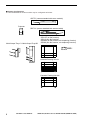
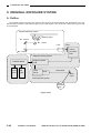
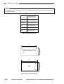
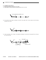
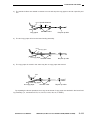
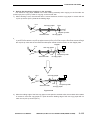
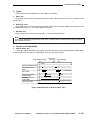
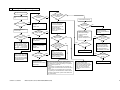
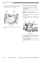
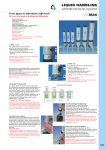
■ System Configuration
The GP200/GP215 Series machine may be configured as follows:
ADF-F1 (comes standard with some models)
Projector
RDF-G1 (comes standard with some models)
Multi-Output Tray-C1 Multi-Output Tray-B2
GP215F (w/ fax function)
GP215 (w/o fax function)
GP200F (w/ fax function, w/o duplexing function)
GP200 (w/o fax function, w/o duplexing function)
Handset
Cassette Feeding Unit-L1
Cassette Feeding Unit-M1
ii
COPYRIGHT © 1996 CANON INC.
CANON GP215/200 REV.0 JULY 1996 PRINTED IN JAPAN (IMPRIME AU JAPON)
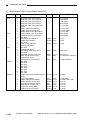
CONTENTS
CHAPTER 1 GENERAL DESCRIPTION
I.
II.
III.
IV.
FEATURES ..............................................1-1
SPECIFICATIONS ...................................1-2
NAMES OF PARTS .................................1-8
A. External View ...................................1-8
B. Cross Section .................................1-10
C. Arrangement of Extension Boards ....1-12
OPERATION ..........................................1-13
A. Turning On the Power Switches .....1-13
V.
VI.
B. Control Panel..................................1-14
C. Basic Operation ..............................1-16
D. Extension Mode..............................1-19
E. Costom Common Settings .............1-25
ROUTINE WORK BY THE USER .........1-29
SAFETY.................................................1-30
A. Laser Beams ..................................1-30
B. Safety of Toner ...............................1-31
CHAPTER 2 COPYING PROCESS
I.
IMAGE FORMATION ...............................2-1
A. Outline ..............................................2-1
B. Latent Image Formation Block .........2-2
C. Pre-Exposure (step 1) ......................2-3
D. Primary Charging (step 2) ................2-3
E. Laser Exposure (step 3)...................2-4
II.
F. Development (step 4) .......................2-4
G. Transfer (step 5) ...............................2-5
H. Separation (step 6)...........................2-6
I. Fixing (step 7)...................................2-7
J. Dram Cleaning .................................2-7
AUXILIARY PROCESS............................2-8
CHAPTER 3 OPERATIONS AND TIMING
I.
II.
III.
IV.
V.
BASIC OPERATION ................................3-1
A. Functional Construction....................3-1
B. Outline of the Electrical Circuitry......3-2
C. Inputs to the Major PCBs .................3-6
D. Main Motor Control PCB ................3-16
ORIGINAL EXPOSURE SYSTEM.........3-20
A. Outline ............................................3-20
B. Varying the Reproduction Ratio .....3-22
C. Sequence of Operations
(original exposure system) .............3-22
D. Scanner Motor................................3-23
E. Controlling the Scanning Lamp ......3-24
F. Identifying the Size of Originals......3-26
IMAGE PROCESSING ..........................3-29
A. Outline ............................................3-29
B. Analog Image Processing ..............3-31
C. Digital Image Processing................3-33
LASER EXPOSURE SYSTEM ..............3-51
A. Laser Processing Assembly ...........3-51
B. Generating the BD Signal ..............3-53
C. Laser Driver Circuit.........................3-54
D. Controlling the Laser Scanner Motor ...3-56
IMAGE FORMATION SYSTEM .............3-58
A. High-Voltage Transformer Circuit ......3-58
B. Controlling the
Primary Charging Roller Bias.........3-60
COPYRIGHT © 1996 CANON INC.
C.
VI.
Controlling the
Transfer Charging Roller Bias ........3-63
D. Controlling the Developing Bias .....3-66
E. Controlling the
Separation Static Eliminator Bias ...3-68
F. Controlling the
Transfer Guide/Fixing Roller Bias ...3-69
G. Developing Assembly/ Drum Cleaner ...3-70
H. Primary Charging Roller
Cleaning Mechanism......................3-73
I. Detecing Errors on the
Composite Power Supply PCB.......3-74
PICK-UP/FEEDING SYSTEM ...............3-76
A. Outline ............................................3-76
B. Pick-Up from the Cassette .............3-79
C. Non-Pick Up Operation (standby)....3-91
D. Detecting the Level of Copy Paper ...3-93
E. Detecting the Size of Copy Paper ...3-95
F. Multifeeder ....................................3-100
G. Controlling the
Registration Roller Clutch.............3-103
H. Making Overlay Copies ................3-104
I. Making Two-Sided Copies............3-106
J. Lower Feeding Assembly .............3-108
K. Fixing/Delivery Assembly .............3-118
L. Delivery Assembly ........................3-127
CANON GP215/200 REV.0 JULY 1996 PRINTED IN JAPAN (IMPRIME AU JAPON)
iii
M. Detecting Jams.............................3-130
VII. FANS ...................................................3-139
A. Functions and Operaitons ............3-139
VIII. POWER SUPPLY ................................3-141
A. Outline ..........................................3-141
B. SLEEP Mode................................3-145
IX. SYSTEM ..............................................3-148
A. Basic Operation ............................3-148
B. Diagram of the Function Boards ..3-150
C. Flow of Image Signals ..................3-154
X. SERVICE MODE .................................3-158
A. Outline ..........................................3-158
B. Using Service Mode .....................3-159
C. Using Adjustment Mode and Settings
Mode.............................................3-160
D. *1* DISPLAY (control display mode)...3-161
XI.
E. *2* I/O DISPLAY(I/O display mode)....3-178
F. *3* ADJUST (adjustment mode) ..3-197
G. *4* FUNCTION (function mode) ...3-208
H. *5* OPTIN (settings mode)...........3-228
I. *6* COUNTER (counter mode) ....3-234
J. *7* ACC (accessory mode) ..........3-238
K. Electrical System..........................3-242
SELF DIAGNOSIS...............................3-261
A. Copier ...........................................3-261
B. Self Diagnosis of the RDF-G1......3-266
C. Self Diagnosis of the ADF-F1.......3-266
D. Self Diagnosis of the Pedestal .....3-267
E. Self Diagnosis of the
Multi Output Tray -C1 ...................3-267
F. Self Diagnosis of the
Multi Output Tray-12 .....................3-268
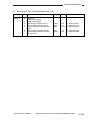
CHAPTER 4 MECHANICAL SYSTEM
I.
II.
III.
IV.
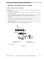
BEFORE THE WORK/
POINTS TO NOTE ..................................4-1
A. Main Power Switch and Others ........4-1
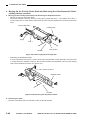
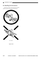
B. Handling the Harnesses ...................4-2
EXTERNALS ...........................................4-3
A. External Covers ................................4-3
B. Inside Cover .....................................4-4
C. Control Panel....................................4-6
D. Fans..................................................4-7
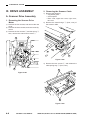
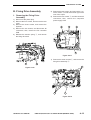
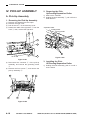
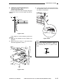
DRIVE ASSEMBLY..................................4-8
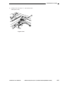
A. Scanner Drive Assembly ..................4-8
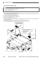
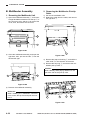
B. Fixing Drive Assembly ....................4-13
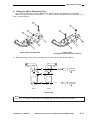
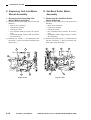
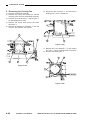
C. Duplexing Unit Inlet Motor Mount
Assembly ........................................4-14
D. Set-Back Roller Motor Assembly....4-14
E. Pick-Up Drive Assembly .................4-15
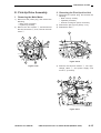
PICK-UP ASSEMBLY ............................4-18
A. Pick-Up Assembly ..........................4-18
B. Multifeeder Assembly .....................4-20
C. Feeding Assembly ..........................4-21
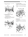
D. Lower Feeding Assembly ...............4-23
E. Registration Roller Assembly .........4-23
F. Delivery Assembly ..........................4-24
V. EXPOSURE...........................................4-27
A. Illuminating Assembly.....................4-27
B. CCD Unit ........................................4-28
C. IPU PCB .........................................4-29
D. Laser Scanner Assembly ...............4-30
VI. DEVELOPING SYSTEM .......................4-32
A. Developing Assembly .....................4-32
VII. FIXING SYSTEM...................................4-34
A. Fixing Assembly .............................4-34
VIII. ELECTRICAL SYSTEM.........................4-37
A. DC Controller PCB .........................4-37
B. Composite Power Supply PCB.......4-37
C. Replacing the ROM DIMM
(image processor PCB) ..................4-38
CHAPTER 5 INSTALLATION
I.
II.
SELECTING THE SITE ...........................5-1
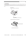
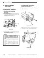
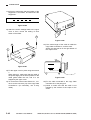
UNPACKING AND INSTALLATION .........5-3
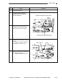
A. Unpacking.........................................5-4
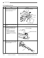
B. Supplying Toner................................5-6
C. Stirring the Toner ..............................5-8
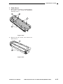
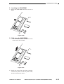
D. Installing the Drum Cartridge .........5-10
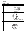
E. Installing the Cassettes ..................5-14
F. Installing the Feeder .......................5-16
III.
IV.
V.
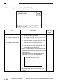
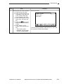
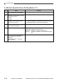
G. Machine Specifications
Setting Mode (*5*) ..........................5-18
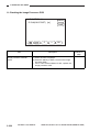
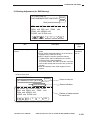
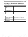
H. Fax Settings (for machines equipped
with fax functions)...........................5-19
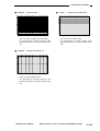
I. Checking the Copy Images ............5-24
RELOCATING THE MACHINE..............5-30
INSTALLING THE CONTROL CARD V....5-31
COPY DATA CONTROLLER-A1 ..............5-34
CHAPTER 6 MAINTENANCE AND SERVICING
I.
II.
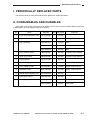
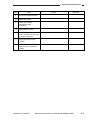
PERIODICALLY REPLACED PARTS ......6-1
CONSUMABLES AND DURABLES ........6-1
iv
COPYRIGHT © 1996 CANON INC.
III.
IV.
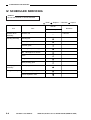
SCHECULED SERVICING CHART ........6-2
SCHEDULED SERVICING......................6-4
CANON GP215/200 REV.0 JULY 1996 PRINTED IN JAPAN (IMPRIME AU JAPON)
APPENDIX
A.
B.
C.
D.
E.
F.
G.
GENERAL TIMING CHART ....................A-1
SIGNALS AND ABBREVIATIONS ..........A-2
GENERAL CIRCUIT DIAGRAM..............A-3
DC CONTROLLER CIRCUIT DIAGRAM...A-7
ANALOG PROCESSOR CIRCUIT
DIAGRAM..............................................A-20
LASER DRIVER CIRCUIT DIAGRAM ..A-24
PICK-UP UNIT CIRCUIT DIAGRAM.....A-26
COPYRIGHT © 1996 CANON INC.
H.
I.
J.
K.
L.
CASSETTE SIZE DETECTION
CIRCUIT DIAGRAM ..............................A-27
FIXING DRIVER CIRCUIT DIAGRAM ..A-28
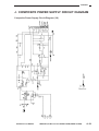
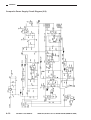
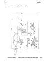
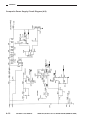
COMPOSITE POWER SUPPLY
CIRCUIT DIAGRAM ..............................A-29
LIST OF SPECIAL TOOLS ...................A-37
SOLVENTS/OILS ..................................A-38
CANON GP215/200 REV.0 JULY 1996 PRINTED IN JAPAN (IMPRIME AU JAPON)
v
CHAPTER 1
GENERAL DESCRIPTION
I.
II.
III.
IV.
FEATURES ..............................................1-1
SPECIFICATIONS ...................................1-2
NAMES OF PARTS .................................1-8
A. External View ...................................1-8
B. Cross Section .................................1-10
C. Arrangement of Extension Boards ....1-12
OPERATION ..........................................1-13
A. Turning On the Power Switches .....1-13
COPYRIGHT © 1996 CANON INC.
V.
VI.
B. Control Panel..................................1-14
C. Basic Operation ..............................1-16
D. Extension Mode..............................1-19
E. Custom Common Settings .............1-25
ROUTINE WORK BY THE USER .........1-29
SAFETY.................................................1-30
A. Laser Beams ..................................1-30
B. Safety of Toner ...............................1-31
CANON GP215/200 REV.0 JULY 1996 PRINTED IN JAPAN (IMPRIME AU JAPON)
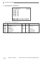
1. GENERAL DESCRIPTION
I. FEATURES
1.
2.
3.
4.
Establishes a new set of standards for “high-quality imaging” at a resolution of 1200 × 600 dpi
(equivalent), which is the world’s first.
• In copier mode, the resolution is 600 × 600 dpi when reading and 1200 × 600 dpi when writing.
• In fax reception mode, the resolution is 600 × 600 dpi (hyper genesis smoothing).
• In printer mode, the resolution is 1200 × 600 dpi (new super smoothing technology).
Ease of operation and productivity from an integrated design.
• The display is a large LCD touch panel for clear viewing and simple operation. (The display
intensity may be varied.)
• The on-going fax communication status may be indicated while in copier mode.
The display indicates the status (reception/transmission) job number, fax number, party number, and number of processing pages at intervals of 1 sec.
Power-saving, space saving, and ozone-less considerations for the office and the environment.
• The on-demand fixing method warms up the machine quickly so that sleep mode may be
made use of without the risk of wasting time.
• The wait time is 8 sec or less. (at power-on on the control panel; 8.6 sec or less if the main
switch is used)
• The machine is appreciably quieter than the existing models for a better office environment.
• With the help of its power-saving design, the power consumption is 4 W or less* in sleep
mode (about 1/25 of existing Canon models) and 57 W or less** in standby (about 1/4 of existing Canon models).
• The roller charging method has enabled ozone-less operation.
• The width is only 58.5 cm. With the MDC function built into the machine, more space is saved.
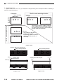
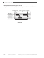
All additional copier, fax, printer, and network functions may be built into the machine without affecting the machine size.
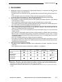
GP215 Series with duplexing functions
• As many as four models are available—with combinations of copier, copier/fax, and copier/printer.
• The copier/fax model comes standard with an ADF-F1 or an RDF-G1.
Copier
Fax
Printer
Duplexing
Copyboard
GP215
GP215F ADF
(GP215FA)
ADF-F1
GP215F RF
(GP215FR)
RF-G1
: Standard
: Option
: Either copyboard cover, ADF-F1, or RDF-G1. (as an option, PostScript Level 2).
* Sleep state is when the main power is OFF. Fax reception is possible. (Not 4 W if a fax transmission
reservation has been made or the printer function has been added.)
** Standby state is when the main power is on. In copier/fax mode, 57 W or less. In copier mode, 50 W
or less.
COPYRIGHT © 1996 CANON INC.
CANON GP215/200 REV.0 JULY 1996 PRINTED IN JAPAN (IMPRIME AU JAPON)
1–1
1. GENERAL DESCRIPTION
II. SPECIFICATIONS
1. Type
Item
Specifications
Body
Desktop
Copyboard
Fixed
Light source
Fluorescent lamp
Lens
Lens array
Photosensitive medium
OPC
2. System
Item
Specifications
Copying
Indirect electrophotographic
Charging
AC roller charging
Exposure
Spot laser
Copy density adjustment
Automatic or manual
Development
Dry, single component toner projection
Automatic
2 cassettes
Manual
Multifeeder (about 5 mm deep)
Pick-up
Transfer
Roller charging
Separation
Static (static eliminator) + curvature
cleaning
Blade
Fixing
SURF
1–2
COPYRIGHT © 1996 CANON INC.
CANON GP215/200 REV.0 JULY 1996 PRINTED IN JAPAN (IMPRIME AU JAPON)
1. GENERAL DESCRIPTION
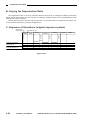
3. Performance
120V
Types of originals
Sheet, book, 3-D object (2 kg max.)
Maximum size of original
A3, (11 × 17) max.
Reprodu
ction
ratio
Direct
1:1±0.5%
Reduce I
1:0.250
Reduce II
1:0.500
230V
Reduce III
1:0.647
–
Reduce IV
1:0.737
–
Reduce V
1:0.786
–
Enlarge I
1:1.214
1:1.414
Enlarge II
1:1.294
–
Enlarge III
1:2.000
Enlarge IV
1:4.000
–
Enlarge V
1:8.000
–
Zoom
1: 0.250 to 8.000 (25% to 800%, in 1% increments)
Wait time
• 8.6 sec or less (20°C) from main power-on to start of copying
• 7.9 sec or less from control panel power-on (sleep) to start of
copying (fax model)
First copy
GP215: 9.2 sec or less (shortest mode)
Continuous copying
100 copies
Copy size
Cassette pick-up
A3 (297 × 420 mm; max.) / 11”×17” (279×432mm:max)
A5 (STMT; min.)
Multifeeder
A3 (297 × 431.8 mm; max.) / 11”×17” (279×432mm:max)
Postcard (A6 vertical)
Paper source
500 sheets in each cassette, 50 sheets in multifeeder
(80 g/m2 paper)
Types of
copy
paper
Cassette
Plain paper (64 to 80 g/m2), tracing paper (SM1, GNT80**),
colored paper*, recycled paper (64 to 80 g/m2), envelope
(COM10, Monarch, DL, C5, B5, No. 4)
Multifeeder
Plain paper (64 to 128 g/m2), tracing paper (GNT80**), transparency*, postcard, label sheet, recycled paper (64 to 80
g/m2), envelope
Twosided/
overlay
copying
Automatic
Multifeeder
Plain paper (64 to 80 g/m2)
Plain paper (64 to 128 g/m2)
(no overlay copying)
*Canon recommended paper.
*May be used but may not feed as expected.
COPYRIGHT © 1996 CANON INC.
CANON GP215/200 REV.0 JULY 1996 PRINTED IN JAPAN (IMPRIME AU JAPON)
1–3
1. GENERAL DESCRIPTION
Cassette
Claw
Non
Regular/universal
55 mm (max.) stacking height (about 500 sheets of 80 g/m2
paper)
Multifeeder tray
50 sheets (80 g/m2)
Delivery tray
100 sheets (approx.; 80 g/m2)
Nonimage
width
Leading/trailing edge
2.5 mm in Direct
Left/right
2.5 mm in Direct
Auto clear
Provided
Auto shut-off
Provided (2-min standard, may be varied between 0 an 9 min
in 1-min increments)
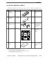
Option
1–4
Feeder
ADF·F1
RF·G1
Sorter
Multi-Output Tray -C1
Multi-Output Tray -B2
Pedestal
Cassette Feeding Unitl-L1
Cassette Feeding Unitl-M1
Others
Handset-A1
Control Card V
Film Projector
COPYRIGHT © 1996 CANON INC.
CANON GP215/200 REV.0 JULY 1996 PRINTED IN JAPAN (IMPRIME AU JAPON)
1. GENERAL DESCRIPTION
4. Others
Operating environment
Power
supply
Temperature
7.5° to 32.5°C
Humidity
5% to 85%
Atmospheric pressure
0.8 to 1.0 atm
120 V
Serial number
GP200: NFY xxxx
GP200F:NFZ xxxx
Power
consumption
Noise
220 / 240V
GP215:UBY xxxx, QFY xxxx, SFY xxxx, TFY xxxx, UFY xxxx.
GP215F:UBZ xxxx, QFZ xxxx, SFZ xxxx, TFZ xxxx, UFZ xxxx.
Maximum
1.5 kW or less
Standby
0.080 kWh (reference only)
Continuous copying
0.750 kWh (reference only)
Quick start mode
(SLEEP 1)
0.045 kWh (reference only)
Power saving mode
(SLEEP 2)
0.003 kWh (reference only)
Copying
66 dB or less (sound power level)
Standby
40 dB or less (sound power level)
Ozone
Dimensions
0.01 ppm or less (average); 0.02 ppm or less (max.)
Width
585 mm (pedestal, copyboard cover)
Depth
700 mm (pedestal, ADF)
Height
571 mm (pedestal, RDF)
Weight
Consuma
bles
GP215
Copy paper Toner
COPYRIGHT © 1996 CANON INC.
Body only
(w/ copyboard cover)
72.4kg
w/ ADV
77.1kg
w/ RDF
84.7kg
Keep copy paper wrapped to protect against humidity.
CANON GP215/200 REV.0 JULY 1996 PRINTED IN JAPAN (IMPRIME AU JAPON)
1–5
1. GENERAL DESCRIPTION
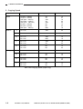
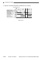
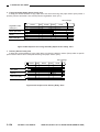
5. Copying Speed
Reproduction ratio
Copy paper size
Copies/min
A3 (297 × 420mm)
A4 (210 × 297mm)
A4R (297 × 210mm)
A5 (148.5 × 210mm)
A5R (210 × 148.5mm)
B4 (267 × 364mm)
B5 (182 × 257mm)
B5R (257 × 182mm)
A3
A4
A4R
A5
A5R
B4
B5
B5R
12
21
16
22
22
13
22
18
II
A3 → A5
A5R
20
III
A3 → B5
B5R
18
IV
A3 → A4
B4 → B5
A4R
B5R
15
18
V
B4 → A4
B5 → A5
A4R
A5
16
22
VI
A3 → B4
A5 → B5
B4
B5
13
22
II
A5 → A3
A3
12
III
A4 → A3
B5 → B4
A3
B4
12
14
IV
A4 → B4
A5 → B5
B4
B5
14
22
V
B4 → A3
B5 → B4
A3
B4
12
14
Direct
Reduce
Enlarge
Size
Table 1-201 Copying Speed (copier only)
1–6
COPYRIGHT © 1996 CANON INC.
CANON GP215/200 REV.0 JULY 1996 PRINTED IN JAPAN (IMPRIME AU JAPON)
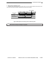
1. GENERAL DESCRIPTION
Ratio
DIRECT
REDUCE
ENLARGE
Size
Copies/min
LTR
20
11×17
11
LGL
14
LTRR
17
STMT
22
STMT-R
20
LGL → LTRR
17
11×17 → LGL
15
11×17 → LTRR
16
11×17 →STMTR
19
11×15 → LTRR
16
LGL → 11×17
12
LTR·R → 11×17
12
STMTR → 11×17
12
Table 1-202 Copying Speed (copier only)
Specifications subject to change for product improvement.
COPYRIGHT © 1996 CANON INC.
CANON GP215/200 REV.0 JULY 1996 PRINTED IN JAPAN (IMPRIME AU JAPON)
1–7
1. GENERAL DESCRIPTION
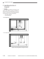
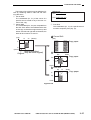
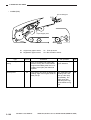
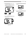
III. NAMES OF PARTS
A. External View
• Model with ADF-F1 as Standard
• Model with RDF-G1 as Standard
10
2
3
9
4
1
5
6
8
7
FIG.1-302
Figure 1-302
Figure 1-301
q
w
e
r
t
Deliery tray
RDF-G1
Control panel power switch
Original delivery tray (for RDF)
Multifeeder
1–8
COPYRIGHT © 1996 CANON INC.
y
u
i
o
!0
Main power switch
Cassette Feeding Unit-L1 (option)
Front door
ADF-F1
Original delivery tray (for ADF)
CANON GP215/200 REV.0 JULY 1996 PRINTED IN JAPAN (IMPRIME AU JAPON)
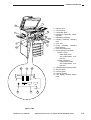
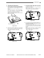
1. GENERAL DESCRIPTION
3
2
q
w
e
r
4
1
5
6
9
7
t
y
u
i
8
o
!0
10
11
!1
!2
!3
!4
!5
12
SLEEP 1
Delivery door
Control panel
Copyboard glass
Developing assembly releasing lever
Developing assembly
Feeding assembly releasing
lever
Drum unit
Fixing assembly releasing
lever opening
Door switch assembly
Power saving mode switch
• SLEEP 1 (top):
Quick start mode
Anti-condensation function ON
• SLEEP 2 (bottom):
Power saving mode
Anti-condensation function OFF
Cassette heater (option) switch
Service switch
Counter (total)
Counter (printer)
LCD display contrast adjustment
SLEEP 2
14
15
13
Figure 1-303
COPYRIGHT © 1996 CANON INC.
CANON GP215/200 REV.0 JULY 1996 PRINTED IN JAPAN (IMPRIME AU JAPON)
1–9
1. GENERAL DESCRIPTION
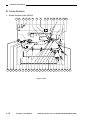
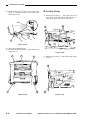
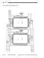
B. Cross Section
1. Cross Section of the GP215
1 2
3
4
5
6
7
8
9 10 11 12 13 14 15 16
39 38 37 36 35 34 33 32 31 30 29 28 27 26 25 24 23 22 21 20 19 18 17
Figure 1-304
1–10
COPYRIGHT © 1996 CANON INC.
CANON GP215/200 REV.0 JULY 1996 PRINTED IN JAPAN (IMPRIME AU JAPON)
1. GENERAL DESCRIPTION
q
w
e
r
t
y
u
i
o
!0
!1
!2
!3
!4
!5
!6
!7
!8
!9
No. 3 mirror
No. 2 mirror
No. 1 mirror
Scanning lamp (fluorescent lamp)
Laser unit
Drum cleaner assembly
Pre-exposure lamp
Lens
Primary charging roller
Drum unit
CCD
Laser mirror
Dust-proofing glass
Developing assembly
Multifeeder pick-up roller
Multifeeder tray
Vertical path roller 1
Vertical path roller 2
Cassette pick-up feeding (lower)
COPYRIGHT © 1996 CANON INC.
@0
@1
@2
@3
@4
@5
@6
@7
@8
@9
#0
#1
#2
#3
#4
#5
#6
#7
#8
#9
Cassette pick-up feeding (upper)
Cassette 2 separation roller
Cassette 2 feeding roller
Cassette 2 pick-up roller
Cassette 1 separation roller
Cassette 1 feeding roller
Cassette 1 pick-up roller
Lower feeding assembly outlet roller
Registration roller
Transfer roller
Separation static eliminator
Set-back roller
cassette 1
Feeding assembly
Fan
Cassette 2
Fixing assembly
Delivery roller 1
Paper deflecting plate
Delivery roller 2
CANON GP215/200 REV.0 JULY 1996 PRINTED IN JAPAN (IMPRIME AU JAPON)
1–11
1. GENERAL DESCRIPTION
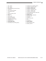
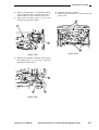
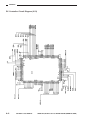
C. Arrangement of Extension Boards
1. Arrangement
1
2
3
10
9
8
4
7
6
5
Figure 1-306
q
w
e
r
t
SCSI Board
CIST Board
CORE/IP Board
FAX Motherboard
Printer board
1–12
COPYRIGHT © 1996 CANON INC.
y
u
i
o
!0
System Motherboard
System Power Supply
Protocol Controller Board
Network Interface Board
G3FAX board
CANON GP215/200 REV.0 JULY 1996 PRINTED IN JAPAN (IMPRIME AU JAPON)
1. GENERAL DESCRIPTION
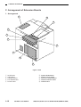
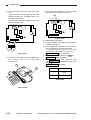
IV. OPERATION
A. Turning On the Power Switches
The machine offers two power switches: main power switch and control panel power switch.
You must first turn on the main power switch and then the control panel switch whenever you are turning on both switches.
3
1
2
Figure 1-401
q Control panel power switch
w Main power switch
e Main power supply lamp
COPYRIGHT © 1996 CANON INC.
CANON GP215/200 REV.0 JULY 1996 PRINTED IN JAPAN (IMPRIME AU JAPON)
1–13
1. GENERAL DESCRIPTION
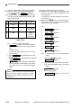
B. Control Panel
1
2
3
COPY
FAX
OPTIONS
12
4
ON/OFF
Clear
Reset
1
2
3
4
5
6
7
8
9
Guide
C
Stop
User mode
0
Start
11 10 9 8
7
6
5
Figure 1-402
q
w
e
r
t
y
Copier key
Fax key
Extension key*
Clean key
Stop key
Start key
*If for North America, ‘PRINT I/F’.
1–14
COPYRIGHT © 1996 CANON INC.
u
i
o
!0
!1
!2
Keypad
Interrupt key
User mode key
Guide key
Reset key
Power supply lamp
CANON GP215/200 REV.0 JULY 1996 PRINTED IN JAPAN (IMPRIME AU JAPON)
1. GENERAL DESCRIPTION
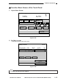
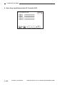
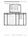
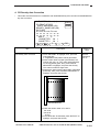
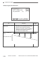
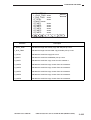
■ Function Basic Screen of the Touch Panel
1. Copier Basic Screen
Ready to copy.
100%
R
1
AUTO
1:1
PAPER
SELECT
E
ZOOM
A
TWOSIDED
SORTER
A
SPECIAL
FEATURES
Figure 1-403
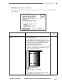
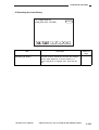
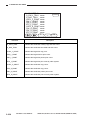
2. Fax Basic screen
• Press the Fax key to open this screen.
Ready to send.
00:00
STANDARD STD
RESOL.
CODED
DIALING
DENSITY
TEXT
IMAGE
QUALITY
ON-HOOK
AUTO
RX
DIRECT
REDIAL
SPECIAL
FEATURES
FAX
MONITOR
Figure 1-404
Note:
For details, see the Fax Service Manual.
COPYRIGHT © 1996 CANON INC.
CANON GP215/200 REV.0 JULY 1996 PRINTED IN JAPAN (IMPRIME AU JAPON)
1–15
1. GENERAL DESCRIPTION
C. Basic Operation
1. Functions Keys
Of the keys on the screen, you may select any of the following on the screen:
R
.............120V:78, 73, 64, 50, 25 (%)
230V:50, 25 (%)
E
.............120V: 121, 129, 200, 400, 800 (%)
230V:141, 200 (%)
Zoom
.............Ratio display, Auto Zoom, +/–, Entire Image, XY Zoom, Zoom Program, Multipage Enlarge
SORTER
.............Sort, Staple Sort, Group (only if sorting unit is installed)
PAPER
SELECT
.............Auto paper selection, stack bypass, cassette
SPECIAL
FEATURES
REC., Transp. INTERLVING, SHIFT, MAREGIN, FRAME ERASE, TWO-PAGE
SEPARATION, MODE ,MEMORY, SHARPNESS, IMAGE CREATION, AREA
DESIG., IMAGE COMB., IMAGE SEPARATION, SHEET OVERLAY, DIF. SIZE
ORIGINAL
Note:
1. No next screen exists for Direct, A, text, or text/photo.
2. Using the Preference key, the most frequently used modes may be selected for display. To select,
use ‘custom copy setting’ in user mode.
3. The DEF. SIZE ORIGINAL key is effective only when an RDF is installed.
1–16
COPYRIGHT © 1996 CANON INC.
CANON GP215/200 REV.0 JULY 1996 PRINTED IN JAPAN (IMPRIME AU JAPON)
1. GENERAL DESCRIPTION
2. Operations Available during
Copying
q Stopping Copying
To stop continuous copying, press the Stop
key
or the Reset key
. Copying
will stop after completing the ongoing copying
run.
w Switching from AE Mode to Manual density
Control Mode
You may switch from AE (auto density control)
mode to manual density adjustment mode
during continuous copying.
However, you cannot switch from manual density adjustment mode during continuous copying.
e Interrupting On-Going Copying
To make copies of a different original, press
the Interrupt key to stop the on-going copying.
Note:
The following keys are effective during continuous copying:
a. Stop key
b. Reset key
c. Interrupt key
d. Copy Density key (from AE to manual)
COPYRIGHT © 1996 CANON INC.
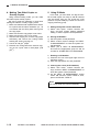
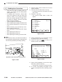
3. Interrupting On-Going Copying
If you want to make copies of a different original while making a large number of copies in continuous copying mode, you can suspend the ongoing copying operation temporarily.
Or, you can suspend fax reception or printer
operation to make copies. (Fax reception or printer operation will resume as soon as you end interrupt mode.)
1) Press the Interrupt key to select interrupt
mode.
Available Operations
• Making one-sided copies
• Making 1 to 100 copies
• Selecting non-sort mode
• Selecting manual feed mode
• Selecting a density (darker, lighter, AE)
• Selecting a reproduction ratio (may be
auto)
• Selecting a cassette
• De-selecting ID mode
• De-selecting interrupt mode
You cannot use the document feeder for interrupt mode.
2) Place the original, and press the Start key.
3) To end interrupt mode, press the Interrupt
mode once again.
CANON GP215/200 REV.0 JULY 1996 PRINTED IN JAPAN (IMPRIME AU JAPON)
1–17
1. GENERAL DESCRIPTION
4. Making Two-Sided Copies or
Overlay Copies
5. Using ID Mode
Using manual feeding mode, you can make
two-sided copies overlay copies.
Be sure to keep the following in mind when
making two-sided or overlay copying mode:
q Make sure that the side copied and the side to
be copied have the same orientation (i.e., do
not reverse rear and front) when turning over
the copy paper.
w Make sure that the copy paper is not moist.
e Make sure that the copy is not curled.
r After the first copying run, cool the copy paper
sufficiently and remove the curling before
starting the second copying run.
t Use 64 to 128 g/m2 paper.
y Remove the curling before the second copying run for a post card or thick paper (128
g/m2).
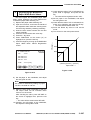
In ID mode, you must enter a 4-digit ID number to make copies. As many as 100 ID numbers
may be stored, and you can check the count
(number of copies made) by number for control of
copying volume by group.
a. Setting the System Control Password
1) Select ‘user mpde’, ‘custom common settings’, and then ‘system settings password
setting’ to set the system control password.
b. Storing ID Numbers
1) Set the system control password.
2) Select ‘custom common settings’ and ‘DEPT.
ID MANAGEMENT’ to enter the system control password.
3) Select ‘yes’ to ‘DEPT. ID MANAGEMENT’,
and store the appropriate group ID and ID
number for ‘STORE DEPT. ID PASSWORD’.
c. Entering an ID Number
1) Press the ‘ID’ icon in the upper right corner of
the Basic screen.
2) Enter the appropriate ‘ID’ and ‘password’.
d. Cleaning the Count (all ID numbers)
1) Select ‘user mode’, ‘custom common settings’, and then ‘DEPT. ID MANAGEMENT’ to
enter the system control password.
2) On the ‘DEPT. ID MANAGEMENT’ screen
select ‘ON’ and then ‘COPY TOTALS’; then,
press ‘CLEAR ALL TOTALS’.
Note:
You cannot clear the counts individually.
1–18
COPYRIGHT © 1996 CANON INC.
CANON GP215/200 REV.0 JULY 1996 PRINTED IN JAPAN (IMPRIME AU JAPON)
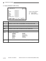
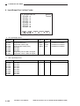
1. GENERAL DESCRIPTION
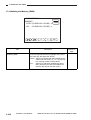
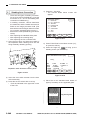
D. Extension Mode
■ Extension Mode Panel (initial screen)
TWO-PAGE
SEPARATION
TRANSP.
INTERLIVING
SHIFT
SHEET
OVERLAY
DIF.SIZE
ORIGINAL
MARGIN
AREA
DESIG.
SHARPNESS
FRAME
ERASE
IMAGE
CREATION
IMAGE
COMB.
IMAGE
SEPARATION
MODE
MEMORY
REC.
DONE
Figure 1-405
COPYRIGHT © 1996 CANON INC.
CANON GP215/200 REV.0 JULY 1996 PRINTED IN JAPAN (IMPRIME AU JAPON)
1–19
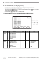
1. GENERAL DESCRIPTION
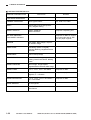
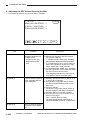
■ SPECIAL FEATURES Screen
SPECIAL FEATURES screen
Next screen
Remarks
TWO-PAGE SEPARATION
TRANSP. INTERLVING
Stack bypass Select
SHIFT
Center Shift, Corner Shift (8 directions), Keypad Setting
SHEET OVERLAY
SHEET OVERLAY
BOOK OVERLAY
DIF. SIZE ORIGINAL/
THIN SHEET ORIGINAL
A4, A4R, LTR, LTRR
Requires a duplexing unit.
Requires an RDF for original
mix size mode and an ADF
for thin paper originals.
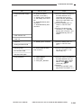
MARGIN
Left margin, Right margin, Top margin, Bottom margin
AREA DESIG.
Area Desig. (editor or keypad),
Framing, Blanking, Negative/Positive
Reversal
SHARPNESS
Soft to Hard (9 steps)
FRAME ERASE
Sheet Frame Erasing, Original Frame
Erasing, Book Frame Erase, Binding
Erase
IMAGE CREATION
Mirror Image, Image Repeat,
Negative/Positive Reversal, Slant image.
IMAGE COMB.
2-on-1, 4-on-1, 2-on-1 Two-Sided
Requires an RDF.
PROJECTOR
35mm Negative, 35mm Positive, 4 × 5
Negative, 4 × 5 Positive
Requires a projector.
IMAGE SEPARATION
1-on-2, 1-on-4, 1-on-2 / One-sided, 1on-4 / One-Sided
Requires an RDF.
MODE MEMORY
M1 through M5
REC.
Most Recent, 2nd Most Recent, 3rd
Most Recent
1–20
COPYRIGHT © 1996 CANON INC.
CANON GP215/200 REV.0 JULY 1996 PRINTED IN JAPAN (IMPRIME AU JAPON)
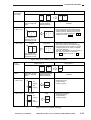
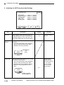
1. GENERAL DESCRIPTION
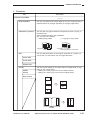
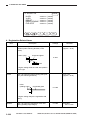
1. Functions
Key
Description
SPECIAL FEATURES
Page Separation
You can copy both left and right pages of an open original (book) on
separate sheets by a single operation (on a single page basis).
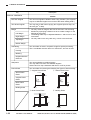
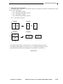
Transparency Interleaf
You can add copy paper between transparencies when copying on
transparencies.
Set the transparencies in the multifeeder.
(Or, you may use a feeder).
q Adding Copy Paper
w Copying on Copy Paper
1
Transparency
Added copy paper
Shift
1 1
2 2
2
Transparency
Added copy paper with copied images
You can shift the position of the original anywhere for copying. For
corner shift, you may select one from eight directions.
Center Shift
Corner Shift
Keypad Shift
Overlay
SHEET
Overlay
You can lay two images on the same side of a single sheet of copy
paper in any of three ways:
• Making an overlay copy from two one-sided ordinals.
• Making an overlay copy from an open original (book).
Book Overlay
A
A
B
B
A
COPYRIGHT © 1996 CANON INC.
B
A
B
CANON GP215/200 REV.0 JULY 1996 PRINTED IN JAPAN (IMPRIME AU JAPON)
1–21
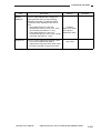
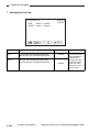
1. GENERAL DESCRIPTION
Description
Key
SPECIAL FEATURES
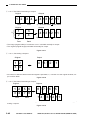
DIF. Size Original
You can use originals of different sizes using a feeder. (The originals
may be of different lengths but must be of the same feeding width.)
Thin Sheet Original
You may use an ADF when copying thin originals (invoice slips, etc.;
35 to 50 g/m2 or less).
Margin
• You may move an image to the front or the rear in sub scanning
direction by specifying a distance so as to create a margin on the
left/right of the output.
• The binding width may be adjusted between 1 and 20 mm in 1mm
increments.
• You may select cover only, back only, or both cover and back.
Left Margin
Right Margin
Top Margin
Bottom Margin
Area Desig.
You can select an area in a specific image for special processing.
The X coordinate must be 432 mm or less and Y, 297 mm or less.
Framing
Blanking
Negative/Positive
Reversal
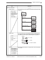
Sharpness
You can emphasize or subdue images.
You may select one from nine different degrees.
Select ‘hard’ for crisp characters and lines or ‘soft’ for photos.
Frame Erase
You can select from among the following four types of frame erasing:
q Original Frame Erase
w Sheet Frame Erase
Sheet Frame
Erase
7mm
2.5mm
2.5mm
7mm
Original Frame
Erase
Original
Book Frame
Erase
Copy
2.5mm
2.5mm
Binding Erase
7mm
7mm
e Book Frame Erase
r Binding Erase
2.5mm
2.5mm
2.5mm
10mm
2.5mm
1–22
COPYRIGHT © 1996 CANON INC.
1~20mm
CANON GP215/200 REV.0 JULY 1996 PRINTED IN JAPAN (IMPRIME AU JAPON)
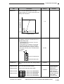
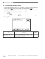
1. GENERAL DESCRIPTION
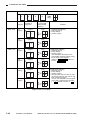
Description
Key
SPECIAL FEATURES
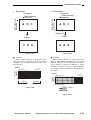
Image Creation
Mirror Image
You can select any of the following modes after pressing the Image
Create key.
Original
Image Repeat
Negative/Positive
Reversal
Slant Image
DEF
Slant mode
Slect from between +45 and
-45 .
Mirror mode
Select from three patterns.
Image repeat mode
Specify 2 to 20 repetitions
in main scanning direction.
DEF
F
DE
DEF
DEF
DEF
Negative / positive reversal
DEF
Image Comb.
2-on-1
4-on-1
2-on-1 TwoSided
Projector
You can reduce two or four originals to copy on a single sheet of
copy paper. For details, see the Operator’s Manual, as the specifics
vary depending on the copier model and options configuration.
Original
AB
A B
2 in 1 mode
ABC
D
A B
C D
4 in 1 mode
ABC
D
A B
2 in 1 mode Two-Sided
You can use a film projector to copy photo film, which may be either
of four types.
35mm Negative
35mm Negative
4 × 5 Negative
4 × 5 Positive
COPYRIGHT © 1996 CANON INC.
CANON GP215/200 REV.0 JULY 1996 PRINTED IN JAPAN (IMPRIME AU JAPON)
1–23
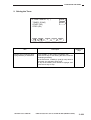
1. GENERAL DESCRIPTION
Key
Description
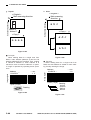
Special Features
Separation image
You can divide a single original into several parts for enlargement and copying on one side of several copies.
1-on-2 One-Sided to
One-Sided
1-on-4 One-Sided to
One-Sided
A B
AB
A B
AB
C D
1-on-2 Two-Sided to
One-Sided
A B
1-on-4 Two-Sided to
One-Sided
A B
C D
Mode Memory
AB
A
B
E
C
D
1 on 2 One-Sided
to One-Sided
1-on-2 One-Sided
to One-Sided
CD
1 on 4 One-Sided
to One-Sided
1-on-4 One-Sided
to One-Sided
CD
1 on 2 Two-Sided
to One-Sided
1-on-2 Two-Sided
to One-Sided
1 on 4 Two-Sided
to One-Sided
1-on-4 Two-Sided
to One-Sided
F
G
H
You can store as many as five combinations of any copying modes. In addition, you may store the name of each mode key.
M1 through M5
REC.
You can recall a copying mode which has been stored previously for use; as
many as three modes may be recalled.
Most Recent
2nd Most Recent
3rd Most Recent
User Mode
Auto Sort
You can opt for automatic switching to sort mode when an original is placed
in the RDF.
(This is effective when the Multi Tray 12 and an RDF are installed.
Face Down Output
You can opt for reversed delivery of copies so that the backs of the copies
are upward.
Projector
You can opt for displaying the Projector key as part of extension mode.
Photo Mode
You can select the use of photo mode. When ‘ON’ is selected, the Photo key
will be displayed on the Copier Basic screen.
Standard Key 1/2 setting
You can select up to two Preference keys from among the extension mode
keys for display on the Copier Basic screen.
Custom Setting Initialize
You can initialize the copier specifications settings to factory defaults.
Standard settings
You can store/initialize the combination of copying modes in response to
power-on or a press on the Reset key.
Store
Init.
1–24
COPYRIGHT © 1996 CANON INC.
CANON GP215/200 REV.0 JULY 1996 PRINTED IN JAPAN (IMPRIME AU JAPON)
1. GENERAL DESCRIPTION
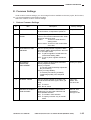
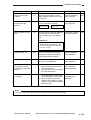
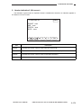
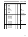
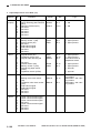
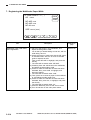
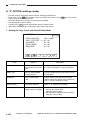
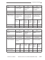
E. Common Settings
Under custom common settings, you can manage functions available to the user (copier, fax functions,
etc.) or execute adjustment and cleaning modes.
Start user mode for custom common settings.
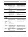
1. Custom Common Settings
No.
Item
Description
Factory settings
1
INITIAL FUNCTION
Use it to select initial functions; i.e., copier
or fax functions, in response to power-on.
Copier functions
2
AUTO-CLEAR SETTINGS
Use it to specify whether to return or not to
return to the functions selected under ‘initial
functions’ after auto clear.
Return:
To return to initial function
setting mode.
Do not return: To return to the mode before
auto clear.
Return
3
SYSTEM DIFF SIZE
ORIGINAL
Use it to specify whether originals of different feeding widths will be placed in the feeder in non-copier mode.
ON: To place originals of mixed sizes but
of the same feeding width.
OFF: To not to place originals of different
sizes.
ON
4
AUTOMATIC
EXPOSURE
ADJUSTMENT
Use it to select the appropriate automatic
density adjustment mode.
Priority on Speed:
To use text mode for density adjustment.
No pre-scanning
Priority on Image Quality:
To execute pre-scanning to identify
image/image quality, text, text/photo
mode.
Priority on speed
5
AUDIBLE TONES
Use it to specify whether to sound or not
sound the three buzzers (input, alarm, job
end).
ON: To sound
OFF: Not to sound
Input: ON
Alarm: ON
Job end: ON
6
DRAWER ELIGIBILITY
FOR APS/ADS
Use it to select cassette holders/manual
feeding tray for auto paper selection and
auto cassette selection.
ON: To include in auto selection.
OFF: To specify inclusion only in manual
mode.
Manual: OFF
Cassettes 1
through 6: ON
COPYRIGHT © 1996 CANON INC.
CANON GP215/200 REV.0 JULY 1996 PRINTED IN JAPAN (IMPRIME AU JAPON)
1–25
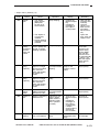
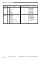
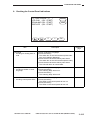
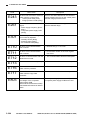
1. GENERAL DESCRIPTION
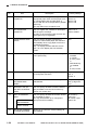
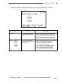
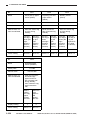
No.
Item
Description
Factory settings
7
STORE SPECIAL
CASSETTE
Use it to select and register the paper
appropriate paper sizes and the paper icons
for colored paper and recycled paper; 2
each of AB- and Inch-configurations. (default
sizes only)
You may select up to 16 paper icons.
SPC1:
SPC2:
SPC3:
SPC4:
8
SET ENVELOPE
CASSETTE
Use it to register the cassette for envelopes
and the type of envelope.
As many as six envelope types and two cassette types may be registered.
ENV1: No. 4
ENV2: COM10
9
STACK BYPASS SIZE
ENTRY
Use it to specify whether to display the
screen for manual feed paper size selection
automatically when copy paper is set in the
multifeeder assembly.
ON: To display the size selection screen.
OFF: To not to display the size selection
screen.
OFF
10
TRAY.
Use it to specify the use of the Multi Tray
3/12’s special tray.
• With Multi Tray-3
Installed,
A: Copier
B: Fax, printer
C:
• With Multi-tray
12 Installed
A:
B: Fax, Printer
11
PRINTING PRIORITY
Use it to specify printing priority for copier,
fax, and printer functions.
Copier: 1
Fax: 2
Printer: 3
12
SET SYSTEM
SETTINGS PASSWORD
Use it to set the ID number for the System
Administrator.
As specified by the
user (4-digit number).
13
RESTRICT USE OF
FAX WITH CONTROL
CARD
Use it to specify whether to limit the individuals permitted to use the fax functions by
means of a control card.
No
14
DEPT. ID MANAGEMENT
Use it to specify whether the function should
be controlled by group.
You may store/confirm up to 100 groups
(group ID and ID numbers).
ID control by
group: No
ID number registration: No
STORE DEPT.
ID/PASSWORD
A4
A4
LTR
LTR
COPY TOTALS
15
1–26
INITIALIZE COMMON
CUSTOM SETTINGS
Allows you to return the custom settings to
their defaults.
COPYRIGHT © 1996 CANON INC.
—
CANON GP215/200 REV.0 JULY 1996 PRINTED IN JAPAN (IMPRIME AU JAPON)
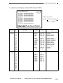
1. GENERAL DESCRIPTION
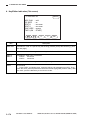
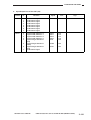
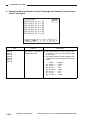
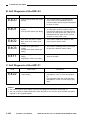
2. Timer Setting
No.
Item
Description
Factory settings
1
DATE/TIME
Use it to set the current date and time.
You may use continuous 4-digit
numbers.
2
AUTO SLEEP TIME
Use it to set the time between key operation
and start of sleep state by automatically
turning off the control panel power switch.
5, 10,20, 30 min; 1 to 8 hr; use service
mode (*5*; SHUT_OFF) to turn ON/OFF
auto sleep time setting.
5 min
3
AUTO CLEAR TIME
Use it to set the time between key operation
and start of the Basic screen automatically.
0: No auto clear
1–9: Set in 1-min increments
2 min
4
TIME UNTIL UNIT
QUIETS DOWN
Use it to set the time between copying operation and start of quiet mode.
0–9: Set in 1-min increments.
2 min
5
DAILY TIMER SETTINGS
Use it to set the time at which the control
panel power switch is automatically turned
off at a specific time on specific days of the
week.
None (may be any
day from Sunday
to Saturday)
COPYRIGHT © 1996 CANON INC.
CANON GP215/200 REV.0 JULY 1996 PRINTED IN JAPAN (IMPRIME AU JAPON)
1–27
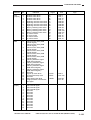
1. GENERAL DESCRIPTION
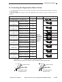
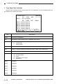
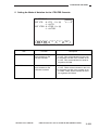
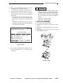
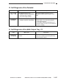
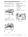
3. Adjustment/Cleaning
The machine is adjusted before shipment from the factory, but the type of copy paper or original can
cause discrepancies in relation to original sizes and densities. To correct such problems, the user may execute the following modes for adjustment/cleaning.
Factory settings
No.
Item
Description
1
Zoom Fine-Adjustment
Use it to fine adjust slight discrepancies
noted between original and copy sizes in
relation to vertical and horizontal reproduction ratios.
Range: –1.0% to +1.0%
Unit:
0.1%
0
2
Exposure Recalb.
Use it with the density adjustment memory
at its center value to adjust the copy density
when making copies of a typical original
(without dirt or fogging).
5*
1~9
3
Feeder Cleaning
Use it to clean the pick-up roller assembly
by placing copy paper in the feeder and circulating it inside the feeder.
None
4
Roller Cleaning
Use it to clean the roller cleaning assembly
if copies are soiled.
None
1–28
COPYRIGHT © 1996 CANON INC.
CANON GP215/200 REV.0 JULY 1996 PRINTED IN JAPAN (IMPRIME AU JAPON)
1. GENERAL DESCRIPTION
V. ROUTINE WORK BY
THE USER
Advise the user to clean the following at leas
once a week:
1) Copyboard Glass
Wipe it with a moist cloth; thereafter, dry wipe
it.
2) Copyboard Cover/RDF Feeding Belt
Wipe them with a cloth moistened with a solution of mild detergent; then, dry wipe them.
COPYRIGHT © 1996 CANON INC.
Advise the user to perform the following when
image faults (e.g., vertical white spots) are noted:
1) Clean the charging roller and the transfer
roller in user mode.
2) Clean the separation static eliminator.
CANON GP215/200 REV.0 JULY 1996 PRINTED IN JAPAN (IMPRIME AU JAPON)
1–29
1. GENERAL DESCRIPTION
VI. SAFETY
A. Laser Beams
Since laser beams can be haemful to the
human body, the copier’s scanner system is
enclosed within a protective housing and external
covers, thereby preventing leakage of laser
beams outside.
For this reason, there is no likehood of the
user’s coming into contact with laser beams.
The copier is approved as a Class 1 laser
product under IEC825 and, in the USA, as Class
under the Code of Federal Regulations (1040.10
of Title 21); see the label in Figures 1-601 and 602 (115/220/240V models only).
CANON
30-2,SHIMOMARUKO,3-CHOME,OHTAKU,TOKYO,
146,JAPAN.
WARNING:
Do not insert a screwdriver having a
high reflectance or light-reflecting
objects into the laser path when servicing around the machine's laser system.
Be sure to remove watches, rings, or
accessories before servicing the
machine.
A laser beam is a visible light, and can cause
permanent damage to the eye.
You will see a label (Figure 1-603) on some
covers of the machine; take extra care when servicing mechanisms under such covers.
FS5-8624
DANGER- Laser radiation when open.
AVOID DIRECT EYE EXPOSURE.
MANUFACTURED:
THIS PRODUCT CONFORMS WITH CDRH RADIATION
PERFORMANCE STANDARD 21 CFR CHAPTER 1
SUBCHAPTER J.
Figure 1-601 120V Model
LASER KLASSE 1
APPAREIL
ARAYONNEMENT
LASER DE CLASSE 1
Figure 1-603
In the copier, the label is attached to the laser scanner system cover, which is used to prevent radiation
of laser lights.
Figure 1-602 220/240V Model
1–30
COPYRIGHT © 1996 CANON INC.
CANON GP215/200 REV.0 JULY 1996 PRINTED IN JAPAN (IMPRIME AU JAPON)
1. GENERAL DESCRIPTION
B. Safety of Toner
Toner is a non-toxic material consisting of
plastic, iron, and small amounts of dye.
If toner comes into contact with the skin or
clothing, remove it with dry tissue and wash with
water.
Do not use hot water, as such will turn the
toner into gel and cause it to fuse with the fibers
of the cloth. Further, do not bring toner into contact with plastic material, as such will initiate
chemical reaction.
Caution:
Do not dispose of toner in fire. It may
explode.
COPYRIGHT © 1996 CANON INC.
CANON GP215/200 REV.0 JULY 1996 PRINTED IN JAPAN (IMPRIME AU JAPON)
1–31
CHAPTER 2
COPYING PROCESS
I.
IMAGE FORMATION ...............................2-1
A. Outline ..............................................2-1
B. Latent Image Formation Block .........2-2
C. Pre-Exposure (step 1) ......................2-3
D. Primary Charging (step 2) ................2-3
E. Laser Exposure (step 3)...................2-4
COPYRIGHT © 1996 CANON INC.
II.
F. Development (step 4) .......................2-4
G. Transfer (step 5) ...............................2-5
H. Separation (step 6)...........................2-6
I. Fixing (step 7)...................................2-7
J. Dram Cleaning .................................2-7
AUXILIARY PROCESS............................2-8
CANON GP215/200 REV.0 JULY 1996 PRINTED IN JAPAN (IMPRIME AU JAPON)
2. COPYING PROCESS
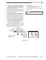
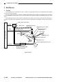
I. IMAGE FORMATION
A. Outline
The GP215/GP200 uses an indirect photographic method of reproduction and is constructed as shown
in Figure 2-101.
Copyboard glass
Scanning lamp
Lens
CCD
Image processing
assembly
Laser scanner assembly Primary charging
roller
Developing
assembly
Pre-exposure
lamp
Drum unit
assembly
Copy paper
Fixing assembly
Copy paper
Static eliminator
Transfer
charging roller
Figure 2-101
Latent image formation block
2.Primary charging
3.Laser exposure
1.Pre-exposure
4.Development
8.Drum cleaning
5.Transfer
Delivery
7.Fixing
6.Separation
Flow of copy paper
Rotation of drum
Registration
Multifeeder
Cassette
Figure 2-102
COPYRIGHT © 1996 CANON INC.
CANON GP215/200 REV.0 JULY 1996 PRINTED IN JAPAN (IMPRIME AU JAPON)
2–1
2. COPYING PROCESS
The GP215/GP200’s image formation process
consists of the following steps as discussed in
sequence:
Step 1 Pre-exposure
Step 2 Primary charging (AC + negative DC)
Step 3 Laser exposure (AC + negative DC bias)
Step 5 Transfer (positive DC)
Step 6 Separation (negative DC)
Step 7 Fixing
Step 8 Drum cleaning
The photosensitive drum has a layer construction: the outside is a photoconducting layer of
OPC and the inside, conductive aluminum substrate.
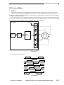
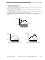
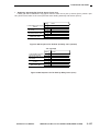
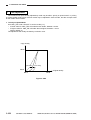
B. Latent Image Formation
Block
The latent image formation block consists of
three steps, at the end of which negative charges
are left behind in the areas on the drum corresponding to the white areas of the original and
negative charges are removed from the areas on
the drum corresponding to the black areas of the
original.
Such images on the drum created by negative
charges are not visible to the human eye and are
therefore called static images.
Time (t)
Photoconductive
Light areas
(dark areas of originals)
Figure 2-103
-1000
Primary charging (step 2)
-500
Pre-exposure (step 1)
Substrate
Surface
potential (V)
Dark areas
(areas not exposured by the laser)
Laser exposure (step 3)
Figure 2-104
2–2
COPYRIGHT © 1996 CANON INC.
CANON GP215/200 REV.0 JULY 1996 PRINTED IN JAPAN (IMPRIME AU JAPON)
2. COPYING PROCESS
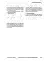
C. Pre-Exposure (step 1)
D. Primary Charging (step 2)
Primary charging roller
Figure 2-106
Figure 2-105
Before executing primary charging, light from
the pre-exposure lamp is directed to the surface
of the drum (pre-exposure), thereby removing
residual charges from the surface and, ultimately,
preventing uneven copy density.
COPYRIGHT © 1996 CANON INC.
The GP 215/GP200 uses a charging roller
made of conducting rubber so as to charge the
photosensitive drum directly for primary charging.
The use of direct charging requires less application voltage than conventional corona charging
and produces virtually no ozone.
An AC bias is applied to stabilize the charges
applied to the photosensitive drum.
The primary charging roller is a special roller
and is not the same as the transfer roller.
CANON GP215/200 REV.0 JULY 1996 PRINTED IN JAPAN (IMPRIME AU JAPON)
2–3
2. COPYING PROCESS
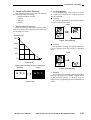
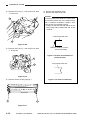
E. Laser Exposure (step 3)
F. Development (step 4)
Laser light
Blade
Cylinder
Dark area Light area
Magnet
Developing
cylinder
Figure 2-107
Figure 2-108
In this step, a laser representing the dark
areas of the original is directed to the surface of
the drum to neutralize the existing charges. The
areas on the photosensitive drum which have
been exposed this way are called light areas and
will later attract toner in step 4 (development).
In this step, the static image on the surface of
the drum is turned into a visible image by toner.
As shown in Figure 2-108, the developing
assembly consists of a developing cylinder (made
of a fixed magnet and a cylinder rotating around
it) and a magnetic blade.
The main ingredients of the toner are magnetite and resins. The toner has insulating properties and is charged to a negative potential by
friction against the cylinder.
The GP215/GP200 deposits toner over the
areas on the surface of the drum whose charges
have been neutralized by a laser beam (light
areas); for this reason, the polarity of the toner is
negative, which is the same as the polarity of primary charging.
Developer
Blade
Concentrated
magnetic field
Magnet
Magnet
Figure 2-109
2–4
COPYRIGHT © 1996 CANON INC.
CANON GP215/200 REV.0 JULY 1996 PRINTED IN JAPAN (IMPRIME AU JAPON)
2. COPYING PROCESS
A concentrated magnetic field occurs from the
magnet to the edge of the blade, attracting toner.
Once inside the field, the toner becomes virtually immobile because of the strong bond with the
blade so that, when deposited, it forms an even,
thin layer on the cylinder.
An AC bias and a DC bias (negative component) are applied to the developing cylinder and
the blade at the same time (developing bias); the
negative component of the developing bias is
stronger than the positive component.
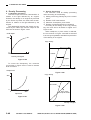
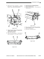
G. Transfer (step 5)
Transfer guide
Transfer
roller
Positive component
Negative component
DC bias
Figure 2-111
Figure 2-110
During copying, toner is attracted to the light
areas of the photosensitive drum by the work of
the negative component of the developing bias,
thereby turning the latent image into a visible
image. The excess toner is removed from the
photosensitive drum by the positive component of
the developing bias and the drum surface potential.
Positive charges are applied to the back of the
copy paper by the transfer roller to transfer the
toner image from the drum surface to copy paper.
The GP215/GP200 uses a roller transfer
method, which requires less transfer voltage than
a corona transfer method and generates virtually
no ozone.
To prevent transfer faults or soiling of the back
of copy paper, the transfer guide is given a negative bias.
Reference:
If the transfer guide was grounded, the
charges for use on the back of copy paper
would escape, leading to transfer faults. If
separated completely, the transfer guide
would be charged, soiling the transfer guide
and ultimately soiling the back of copy paper.
COPYRIGHT © 1996 CANON INC.
CANON GP215/200 REV.0 JULY 1996 PRINTED IN JAPAN (IMPRIME AU JAPON)
2–5
2. COPYING PROCESS
Reference:
If the image on the photosensitive drum was
not fully transferred to the copy paper
because of a jam, toner can stick to the
transfer charging roller.
The GP215/GP200 uses negative transfer
voltage during initial rotation and last rotation
to return any such toner (charged to a negative potential and sticking to the transfer
roller) to the photosensitive drum.
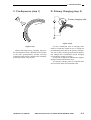
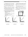
H. Separation (step 6)
Transfer roller
Static eliminator
Transfer roller
Figure 2-113
Figure 2-112
2–6
COPYRIGHT © 1996 CANON INC.
The GP215/200 takes advantage of the rigidity of copy paper to separate paper from the drum
(curvature separation). Since thin paper has little
rigidity,it tends to remain wrapping on the drum.
To prevent such a problem, a negative voltage is
applied to the separation static eliminator, thereby
weakening the static bond between drum and
copy paper for better separation.
CANON GP215/200 REV.0 JULY 1996 PRINTED IN JAPAN (IMPRIME AU JAPON)
2. COPYING PROCESS
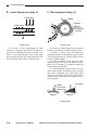
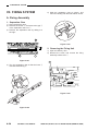
I. Fixing (step 7)
J. Drum Cleaning
Main thermistor (TH1)
Sub thermistor (TH2)
Cleaning blade
Fixing film
Fixing heater
Toner
Blade
Fixing
cleaning roller
Lower fixing roller
Scoop-up sheet
Copy paper
Figure 2-115
Figure 2-114
After transfer, the copy paper is moved through
the fixing film and the lower fixing roller so that the
toner image will be fused into the fibers of the
paper.
The fixing heater is a plane-shaped heater; it
serves to eliminate warm-up time by heating the
area of contact with the fixing film.
The temperature of the fixing heater is monitored by the main thermistor (TH1) located at the
center of the heater. (The fixing heater is controlled to a specific temperature at all times.)
A sub thermistor (TH2) is provided at the end
of the fixing heater to monitor the temperature of
the area which remains free of contact with paper
when small-size paper is moved through the fixing
assembly, thereby preventing overheating.
The fixing cleaning roller is made of aluminum
and is kept in contact with the lower fixing roller to
remove toner from the lower fixing roller. (It also
serves to discharge heat from the lower fixing
roller.)
The metal core of the lower fixing assembly is
given a positive bias to prevent offset of toner to
the fixing film.
COPYRIGHT © 1996 CANON INC.
The toner remaining on the drum surface is
scraped by the cleaning blade in preparation for
the next copy. When scraped off the drum surface,
the toner is collected by the scoop-up sheet and
is forwarded to the rear by the blade.
CANON GP215/200 REV.0 JULY 1996 PRINTED IN JAPAN (IMPRIME AU JAPON)
2–7
2. COPYING PROCESS
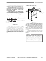
II. AUXILIARY PROCESS
1. Delivery Static Eliminator
Copy paper immediately prior to delivery holds
residual charges from transfer, and a static eliminator (grounded brush) is provided at the delivery
slot to remove such charges.
2–8
COPYRIGHT © 1996 CANON INC.
CANON GP215/200 REV.0 JULY 1996 PRINTED IN JAPAN (IMPRIME AU JAPON)
CHAPTER 3
OPERATIONS AND TIMING
I.
II.
III.
IV.
V.
VI.
BASIC OPERATION ................................3-1
A. Functional Construction....................3-1
B. Outline of the Electrical Circuitry......3-2
C. Inputs to the Major PCBs .................3-6
D. Main Motor Control PCB ................3-16
ORIGINAL EXPOSURE SYSTEM.........3-20
A. Outline ............................................3-20
B. Varying the Reproduction Ratio .....3-22
C. Sequence of Operations
(original exposure system) .............3-22
D. Scanner Motor................................3-23
E. Controlling the Scanning Lamp ......3-24
F. Identifying the Size of Originals......3-26
IMAGE PROCESSING ..........................3-29
A. Outline ............................................3-29
B. Analog Image Processing ..............3-31
C. Digital Image Processing................3-33
LASER EXPOSURE SYSTEM ..............3-51
A. Laser Processing Assembly ...........3-51
B. Generating the BD Signal ..............3-53
C. Laser Driver Circuit.........................3-54
D. Controlling the Laser Scanner Motor ...3-56
IMAGE FORMATION SYSTEM .............3-58
A. High-Voltage Transformer Circuit ......3-58
B. Controlling the
Primary Charging Roller Bias.........3-60
C. Controlling the
Transfer Charging Roller Bias ........3-63
D. Controlling the Developing Bias .....3-66
E. Controlling the
Separation Static Eliminator Bias ...3-68
F. Controlling the
Transfer Guide/Fixing Roller Bias ...3-69
G. Developing Assembly/
Drum Cleaner .................................3-70
H. Primary Charging Roller
Cleaning Mechanism......................3-73
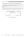
I. Detecing Errors on the
Composite Power Supply PCB.......3-74
PICK-UP/FEEDING SYSTEM ...............3-76
A. Outline ............................................3-76
B. Pick-Up from the Cassette .............3-79
C. Non-Pick Up Operation (standby)....3-91
D. Detecting the Level of Copy Paper ...3-93
COPYRIGHT © 1996 CANON INC.
E. Detecting the Size of Copy Paper ...3-95
F. Multifeeder ....................................3-100
G. Controlling the
Registration Roller Clutch.............3-103
H. Making Overlay Copies ................3-104
I. Making Two-Sided Copies............3-106
J. Lower Feeding Assembly .............3-108
K. Fixing/Delivery Assembly .............3-118
L. Delivery Assembly ........................3-127
M. Detecting Jams.............................3-130
VII. FANS ...................................................3-139
A. Functions and Operaitons ............3-139
VIII. POWER SUPPLY ................................3-141
A. Outline ..........................................3-141
B. SLEEP Mode................................3-145
IX. SYSTEM ..............................................3-148
A. Basic Operation ............................3-148
B. Diagram of the Function Boards ..3-150
C. Flow of Image Signals ..................3-154
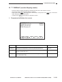
X. SERVICE MODE .................................3-158
A. Outline ..........................................3-158
B. Using Service Mode .....................3-159
C. Using Adjustment
Mode and Settings Mode .............3-160
D. *1* DISPALY
(control display mode) ..................3-161
E. *2* I/O DISPLAY
(I/O display mode) ........................3-178
F. *3* ADJUST (adjustment mode) ..3-197
G. *4* FUNCTION (function mode) ...3-208
H. *5* OPTIN (settings mode)...........3-228
I. *6* COUNTER (counter mode) ....3-234
J. *7* ACC (accessory mode) ..........3-238
K. Electrical System..........................3-242
XI. SELF DIAGNOSIS...............................3-261
A. Copier ...........................................3-261
B. Self Diagnosis of the RDF-G1......3-266
C. Self Diagnosis of the ADF-F1.......3-266
D. Self Diagnosis of the Pedestal .....3-267
E. Self Diagnosis of the
Multi Output Tray -C1 ...................3-267
F. Self Diagnosis of the
Multi Output Tray-12 .....................3-268
CANON GP215/200 REV.0 JULY 1996 PRINTED IN JAPAN (IMPRIME AU JAPON)
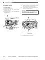
3. OPERATIONS AND TIMING
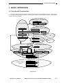
I. BASIC OPERATION
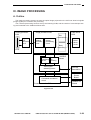
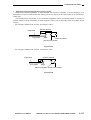
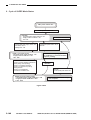
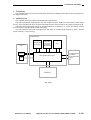
A. Functional Construction
The GP215/GP200 can be divided into seven functional blocks: pick-up/feeding system, original exposure system, image processing system, laser exposure system, image formation system, communication
system, and control system.
<Original exposure system>
Original
<Control system>
Optical path Original illumination
<Image processing system>
Control panel
Analog processor
Image I/F
Image processor
DC controller
Communication system
(fax)
Composite power supply
Laser driver
<Laser exposure
system>
Laser scanner
Charging
Delivery tray
Fixing
Feeding
<Image formation system>
Drum
Drum cleaning
Separation
PDL interpreter
Others
Developing
Transfer
Pick-up control
Lower feeding assembly
Multifeeder
<Pick-up/feeding
system>
Cassette 1
Cassette 2
Cassette 3
Cassette pedestal
(option)
Cassette 4
Cassette 5
Cassette 6
Figure 3-101
COPYRIGHT © 1996 CANON INC.
CANON GP215/200 REV.0 JULY 1996 PRINTED IN JAPAN (IMPRIME AU JAPON)
3–1
3. OPERATIONS AND TIMING
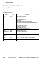
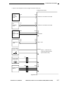
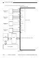
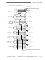
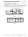
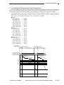
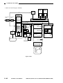
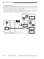
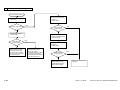
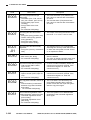
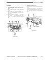
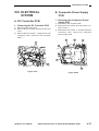
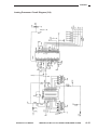
B. Outline of the Electrical Circuitry
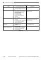
1. Control Division
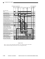
The GP215/GP200’s electrical mechanisms are controller by the CPU on the PCBs shown in Figure 3102. See Table 3-101 for an idea of the functions of the CPU and the functions of the ROMs/RAMs and
the ICs around the CPU.
a. Image Processor PCB
Name
IC No.
CPU
IC506
Description
•
•
•
•
•
•
•
•
•
•
•
•
•
•
Controls image processing
Controls laser operation
Controls job schedules
Controls fax sequence
Controls system memory
Detects errors
Controls DC controller PCB communications
Controls serial communications (for FLASH ROM downloading)
Controls the control panel
Controls the feeder/editor
Controls fax communications
Controls copying sequence
Controls the power supply
Controls control panel communications
Contains control programs
Controls copying operations
Controls fax operations
Control panel message
ROM
(FLASH ROM)
ROM
DIMM
IC1
IC2
•
•
•
•
MASK
ROM
IC564
• Controls fonts (e.g., fonts used for fax headers)
RAM
IC650
IC651
• Stores service mode, user mode, various parameters
DP RAM
IC528
• Controls communication with the DC controller PCB
Table 3-101a
3–2
COPYRIGHT © 1996 CANON INC.
CANON GP215/200 REV.0 JULY 1996 PRINTED IN JAPAN (IMPRIME AU JAPON)
3. OPERATIONS AND TIMING
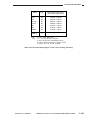
b. DC Controller PCB
Name
IC No.
Description
CPU
IC101
•
•
•
•
•
•
•
•
•
•
•
•
•
Controls pick-up/feeding operations
Controls the pedestal
Controls high-voltage sequence
Controls the laser scanner motor
Detects jams
Controls service mode
Controls the IPC
Controls the sorter
Controls fixing
Controls the main motor
Controls the scanner motor
Detects the cassette/paper
Detects original size
ROM
IC103
IC104
Contains control programs
IPC
IC108
Controls sorter/RDF/ADF combinations
Table 3-101b
c. Composite Power Supply PCB
Name
CPU
IC No.
IC605
Description
•
•
•
•
•
•
Controls the control system power supply
Controls high-voltage
Monitors power switch inputs/anti-condensation switch
Monitors the CI (calling indicator; fax call signal)
Controls the power supplies of loads
Controls the scanning lamp
Table 3-101c
COPYRIGHT © 1996 CANON INC.
CANON GP215/200 REV.0 JULY 1996 PRINTED IN JAPAN (IMPRIME AU JAPON)
3–3
3. OPERATIONS AND TIMING
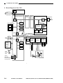
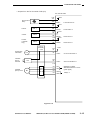
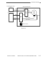
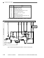
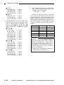
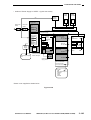
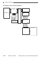
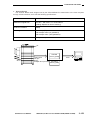
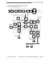
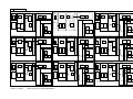
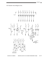
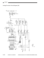
2. Block Diagram of the CPU
Control panel
CPU
Serial
communication
Image processor PC
CORE/IP
Board
FAX
Motherboard
G3FAX Board
Modem
CPU
IC506
ROM SIMM J527
IC1
FLASH
ROM
IC2
FLASH
ROM
IC564
MASK
ROM
IC650
Telephone
line
NCU
Selector
Memory
control
RAM
IC651
RAM
Memory Memory
Coding/
decoding
BAT501
IC528 DP
RAM
DC controller
PCB
M
CPU
IC101 CPU
IC103
DC loads
Clutch
Solenoid
Motor
Sensor
Etc.
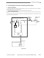
Composite power supply PCB
Q605
Lamp
regulator
circuit
HVT
circuit
DC power
supply
circuit
ROM
IC104
ROM
IC105
RAM
Scanning lamp
Main
motor
Serial communication
-12V 5V 7V
15V 24V
Laser
scanner M
motor
IC108
Sorter
RDF/ADF
Communication
control device
IPC
Figure 3-102
3–4
COPYRIGHT © 1996 CANON INC.
CANON GP215/200 REV.0 JULY 1996 PRINTED IN JAPAN (IMPRIME AU JAPON)
3. OPERATIONS AND TIMING
3. General Block Diagram
Analog
processor PCB
Image processor
PCB
CORE/IP Board
FAX
Motherboard
Image processing
circuit
A/D
Ratio
change
Laser
driver
Memory A Memory B
(expansion) (expansion)
Memory A Memory B Coding/
Video
signal
switching
circuit
Binary
processing
G3 FAX Board
decoding
Memory
controller
Selector
Density
D/A
Telephone
line
NCU
Control panel
CPU
Modem
CPU
DP
RAM
Protocol controller PCB
DP
RAM
Controller
CPU
Command
conversion
circuit
Memory
Host computer
CPU
SCSI
SCSI Board
(option)
Printer board (option)
DP
CPU
RAM
Composite power supply PCB
CPU
IPC
CPU
DC controller PCB
DC loads
Clutch
Solenoid
Motor
Sensor
Etc.
Main
motor
M
M
Laser scanner motor
Lamp
regulator
circuit
HVT
circuit
Scanning lamp
Sorter
RDF/ADF
ASSIST
DC power
supply
Video
controller
24V 15V 7V
5V -12V
DP
RAM
System
Motherboard
CPU
LAN
controller
Network I/F Board
(option)
Figure 3-103
Note:
The CORE/IP Board, FAX Motherboard, and G3 FAX Board come standard with the
GP215F/GP200F but are options for other models (GP215/GP200).
COPYRIGHT © 1996 CANON INC.
CANON GP215/200 REV.0 JULY 1996 PRINTED IN JAPAN (IMPRIME AU JAPON)
3–5
3. OPERATIONS AND TIMING
C. Inputs to the Major PCBs
• Composite Poser Supply Circuit (around the AC power supply)
Sorter
RDF
Main switch
SW1
System
Motherboard
24V
ACC power
supply PCB
Composite power supply PCB
5V
12V
System power
supply PCB
J2
Noise filter
J210
-1
-3
J201
-1
(option)
Front door switch
SW2
DC power
supply circuit
-5
J4
J3
Fluorescent heater
switch
SW4
Fixing heater
H4
J11
Fixing
heater
driver PCB
AC
Fu1
J3
Cassette heater
H1
J209
J102
Scanning lamp
control/HVT
DC controller PCB
J95
J208
-1
J20
FL1 Scanning lamp
-2
-4
-5
J205-3
J205-3
Primary charging roller
Developing assembly
Drum
Transfer guide
J206-1
Static eliminator
Transfer roller
T502
J206-4
J220
Fixing assembly
Figure 3-104
3–6
COPYRIGHT © 1996 CANON INC.
CANON GP215/200 REV.0 JULY 1996 PRINTED IN JAPAN (IMPRIME AU JAPON)
3. OPERATIONS AND TIMING
• Inputs to and Outputs from the Image Processor PCB (1/3)
Image processor PCB
Analog
processor
PCB
DC
controller
PCB
J1001
J512
Checks are not meant for the field.
J111
J509
Checks are not meant for the field.
J5041
-1
Beam
-2
detection (BD) -3
PCB
J504
-1
-2
-3
J603
J602
5V
BD (input)
J518
J519
Laser driver
PCB
See p. 3-54
Power supply
indicator LED
LEDON
When '1', LED turns ON.
(Turns ON when the main
power switch is ON.)
J91
Power saving
mode switch
J183
Control Card V
(option)
J560
-3
-2
-3
-4
5V
Figure 3-105
COPYRIGHT © 1996 CANON INC.
CANON GP215/200 REV.0 JULY 1996 PRINTED IN JAPAN (IMPRIME AU JAPON)
3–7
3. OPERATIONS AND TIMING
• Inputs to and Outputs from the Image Processor PCB (2/3)
Image processor PCB
J505
-1
-2
Original size
sensor 1
5V
DSZ1
-3
J506
-1
-2
Original size
sensor 2
5V
DSZ2
-3
See p.3-26
J507
-1
-2
Original size
sensor 3
5V
DSZ3
-3
J508
-1
-2
Original size
sensor 4
5V
DSZ4
-3
FAX
Motherboard
Board
Checks are not meant for the field.
G3 FAX Board
Figure 3-106
3–8
COPYRIGHT © 1996 CANON INC.
CANON GP215/200 REV.0 JULY 1996 PRINTED IN JAPAN (IMPRIME AU JAPON)
3. OPERATIONS AND TIMING
• Inputs to and Outputs from the Image Processor PCB (3/3)
Image processor PCB
Switching
PCB
Control panel
power supply
switch
LCD
intensity VR
J905 J517
Control panel
CPU PCB
Checks are not meant for the field.
One-touch dial
cover open/closed
detection
Touch panel
LCD
J516
-1
LCD back-light
power supply
-2
5V
BKLTON
*
When '0', the back-light turns
Figure 3-107
COPYRIGHT © 1996 CANON INC.
CANON GP215/200 REV.0 JULY 1996 PRINTED IN JAPAN (IMPRIME AU JAPON)
3–9
3. OPERATIONS AND TIMING
• Inputs to the DC Controller PCB (1/3)
DC controller PCB
Scanner home
position sensor
J107
-A3
-A2
-A1
PS1
J46
Fixing film sensor
PS2
Copyboard cover
open/closed sensor
J113
-B10
-B9
-B8
PS3
J33
Multifeeder paper
sensor
Pre-registration
paper sensor
PS4
PS5
PS7
J33
Vertical path
paper sensor
Right door
open/closed
detection
Waste toner
sensor
J113
-A12
-A11
-A10
J113
-A6
-A5
-A4
J46
Fixing assembly
delivery sensor
J109
-4
-3
-2
J109
-7
-6
-5
5V
SCHP
When the scanner is at home
position, '1'.
(The light-blocking plate is at PS1.)
5V
FFD
When PS2 has detected
the fixing film, '1'.
(The light-blocking plate is at PS2.)
5V
CBCC
When the copyboard or
the feeder is closed, '1'.
(The light-blocking plate is at PS3.)
5V
MFPD
When PS4 has detected paper, '0'.
(The light-blocking plate is not at PS4.)
5V
PDP1
When PS5 has detected paper, '1'.
(The light-blocking plate is at PS5.)
5V
PDP3
5V
PS8
J113
-A3
-A2
-A1
5V
PS9
J113
-A9
-A8
-A7
5V
PS10
J113
-B7
-B6
-B5
PDP4
RDOP
WTDT
When PS7 has detected paper, '1'.
(The light-blocking plate is at PS7)
When PS8 has detected paper, '1'.
(The light-blocking plate is at PS8.)
When the right door is open, '0'.
(The light-blocking plate is not at PS9.)
When the waste toner case
is full, '0'.
(The light-blocking plate
is not at PS10.)
Figure 3-108
3–10
COPYRIGHT © 1996 CANON INC.
CANON GP215/200 REV.0 JULY 1996 PRINTED IN JAPAN (IMPRIME AU JAPON)
3. OPERATIONS AND TIMING
• Inputs to the DC Controller PCB (2/3)
DC controller PCB
J103
-3
-2
-1
J73
Re-pick up
paper sensor
PS11
J79
Duplexing assembly
inlet paper sensor
PS12
J89
Delivery sensor
PS13
J92
Holizontal
registration paper
sensor
J69
J66
PS14
J44
Upper cassette
size detection
J45
Lower casette
size detection
J60
Multifeeder paper
width detection
5V
PDP5
J105
-B3
-B2
-B1
5V
J105
-A3
-A2
-A1
5V
J114
-B3
-B2
-B1
5V
J110
-6
-5
-4
-3
-2
-1
J110
-12
-11
-10
-9
-8
-7
PDP6
PDP7
When PS11 has detected paper, '0'.
(The light-blocking plate is not at PS11.)
When PS12 has detected paper, '0'.
(The light-blocking plate is not at PS12.)
When PS13 has detected paper, '0'.
(The light-blocking plate is not at PS13.)
CRGPD When PS14 has detected the edge
of paper, '0'.
(The light-blocking plate is not at PS14.)
CSZ14
CSZ13
CSZ12
CSZ11
CSZ10
See p. 3-176
CSZ24
CSZ23
CSZ22
CSZ21
CSZ20
See p. 3-176
J113
-A15
-A14
MFPW
(analog signal)
Detects the width of
copy paper stacked
in the multifeeder.
-A13
Figure 3-109
COPYRIGHT © 1996 CANON INC.
CANON GP215/200 REV.0 JULY 1996 PRINTED IN JAPAN (IMPRIME AU JAPON)
3–11
3. OPERATIONS AND TIMING
• Inputs to the DC Controller PCB (3/3)
DC controller PCB
J26
J27 J112 15V -12V
-1
-4
Scanning lamp
intensity sensor
-2
FLS
See p. 3-24
RTEMP
(analog
signal)
Detects the temperature
around the drum.
-3
J105
-B10
-B11
TH
Drum ambient
temperature sensor
J117
-8
-7
-6
Toner sensor
J108
-1
Fixing main
temperature
detection
5V
When the toner inside
the developing assembly is
below a specific level, '0'.
TEP
TH1
-2
J108
-3
Fixing sub
temperature
detection
See p. 3-118
TH2
-4
Upper cassette
delivery detection
Pick-up unit PCB
J114
-5V
-A10
5V
UCSPD
When Q1604 has detected
paper, '1'.
LCSPD
When Q1605 has detected
paper, '1'.
1RPD0
When Q1606 has detected
the lifter, '1'.
2RPD0
When Q1608 has detected
the lifter, '1'.
1RPD1
When Q1607 has detected
the lifter, '1'.
2RPD1
When Q1609 has detected
the lifter, '1'.
Q1604
Lower cassette
delivery detection
Q1605
Upper cassette paper
level detection 0
Lower cassette paper
level detection 0
Q1608
Q1606
Upper cassette paper
level detection 1
Lower cassette paper
level detection 1
J114
-A11
J122
-1
J122
-3
J122
-2
Q1607
J122
-4
Q1609
Figure 3-110
3–12
COPYRIGHT © 1996 CANON INC.
CANON GP215/200 REV.0 JULY 1996 PRINTED IN JAPAN (IMPRIME AU JAPON)
3. OPERATIONS AND TIMING
• Outputs from the DC Controller PCB (1/3)
DC controller PCB
J114
-B4
-B6
-B7
-B5
M1
5V
MMD
MLCK
See p. 3-16
Main motor
24V
0V
J116
-1
-2
-3
-4
-5
J25
Scanner motor
M2
J112
-6
-7
-8
-5
Laser scanner
motor driver
PCB
M3
24V
0V
Laser scanner motor
J109
-8
-9
-10
-11
-12
-13
J49
Fixing Film
M5
J76
Set-back motor
M6
M7
J72
Delivery reversing
motor
(GP215 only)
Horizontal motor
M8
See p. 3-60
24V24V
J103-8
-9
-6
-7
-10
-11
J81
Duplexing assembly
inlet motor
See p.3-23
J105-B6
-B7
-B4
-B5
-B8
-B9
J69
J105-A8
-A9
-A6
-A7
-A10
-A11
J115-1
-2
-3
-4
-5
-6
M9
J68
See p. 3-123
24V24V
See p. 3-110
24V24V
See p. 3-108
24V24V
See p. 3-127
24V24V
See p. 3-114
J99
Figure 3-111
COPYRIGHT © 1996 CANON INC.
CANON GP215/200 REV.0 JULY 1996 PRINTED IN JAPAN (IMPRIME AU JAPON)
3–13
3. OPERATIONS AND TIMING
• Outputs from the DC Controller PCB (2/3)
DC controller PCB
J37
Registration clutch
J114-B10
CL1
-B11
J61
Multifeeder pick-up
clutch
J114-B8
CL2
-B9
J38
Developing clutch
Lower feeding
assembly re-pick up
clutch
-B14
J122-5
CL5
-6
J63
Primary charging
roller cleaning
solenoid
J113-B1
SL1
-B2
J62
Multifeeder holding
plate releasing
solenoid
J114-B12
SL3
-B13
J75
Re-pick up paper
deflecting plate
solenoid
J73
SL4
Delivery assembly
paper deflecting plate
solenoid
J103-4
-5
J71
J69
SL5
J105-A4
-A5
J53
Feeding fan
J51
RGCD*
When '0', CL1 turns ON
24VU
MFCD*
J113-B13
CL4
24VU
J107-A7
-A8
When '0', CL2 turns ON
24VU
DVCD*
When '0', CL4 turns ON
24VU
CL5D*
24VU
When '0', CL5 turns ON
PCLSD*
When '0', CL1 turns ON
24VU
MRSD*
24VU
When '0', SL3 turns ON
RFLD*
When '0', SL4 turns ON
24VU
DFLD*
When '0', SL5 turns ON
24VU
FMD1*
When '0', FM1 rotates.
15V
FM1
J107-A9
Exhaust fan 1
-A10
FM2
24VU
15V
J107-B1
Exhaust fan 2
-B2
FM3
Laser cooling fan
24VU
The CPU control
mechanism switches
between high-speed and
low-speed modes.
15V
J113-B3
-B4
24VU
The CPU control
mechanism switches
between high-speed and
low-speed modes.
15V
FM4
J112-9
System cooling fan
The CPU control
mechanism switches
between high-speed and
low-speed modes.
-10
24VU
The CPU control
mechanism switches
between high-speed and
low-speed modes.
FM5
Figure 3-112
3–14
COPYRIGHT © 1996 CANON INC.
CANON GP215/200 REV.0 JULY 1996 PRINTED IN JAPAN (IMPRIME AU JAPON)
3. OPERATIONS AND TIMING
• Outputs from the DC Controller PCB (3/3)
DC controller PCB
J107
-A11
Pre-exposure
lamp
-A12
J107
-B3
Counter
CNT 1
-B4
J107
-B5
CNT 2
Counter
Counter
(115/230V
only)
-B6
J107
-B5
CNT 3
-B6
Pick-up
assembly
PCB
Vertical path
roller clutch
Cassette
pick-up
solenoid
CL3
J114
-A1
-A4
J114
-A5
SL2
24VR
PEXP*
Turns ON when '0'.
24VU
CNT1D
24VU
Counts when '0'.
CNT2D
24VU
Counts when '0'.
CND3D
Counts when '0'.
24VU
CL3D*
CL3 turns ON when '0'.
SL2D*
SL2 turns ON when '0'.
J114
-A6
Cassette
pick-up motor
M4
Motor
drive
circuit
-A7
-A8
-A9
12A
12B
· While M4 is rotating,
alternates between '1' and '0'.
(pulse signal)
12M0
12M1
· Always '1'.
Figure 3-113
COPYRIGHT © 1996 CANON INC.
CANON GP215/200 REV.0 JULY 1996 PRINTED IN JAPAN (IMPRIME AU JAPON)
3–15
3. OPERATIONS AND TIMING
D. Main Motor Control PCB
3. Controlling the Speed
1. Outline
The main motor (M1) is rotated and stopped in
response to the drive signal (MMD) generated by
the DC controller PCB, thereby driving the following loads:
• Photosensitive drum
• Developing assembly
• Feeding assembly
• Fixing assembly
• Multifeeder pick-up roller
• Registration roller
• Vertical path roller 1/2
• Delivery roller 1
• Lower feeding assembly outlet roller
Its speed, further, is controlled by the main
motor control PCB.
2. Rotation
The main motor is driven by DC + 24 Vu supplied by the composite power supply PCB. When
the drive signal (MMD) generated by the DC controller PCB goes ‘1’, the control circuit on the main
motor control PCB turns ON to drive the drive circuit.
The drive circuit in turn supplies drive current
suited to the control of the control circuit to the
main motor to rotate the motor. At this time, the
output of the hall IC is returned to the drive circuit,
thereby maintaining the rotation of the motor.
3–16
COPYRIGHT © 1996 CANON INC.
The main motor (M1) is a DC motor with a
built-in clock pulse generator which generates
clock pulses (MMCLK) when the motor rotates
according to the revolution of the motor.
The phase of the frequency of these clock
pulses and the phase of the frequency of the reference signal are compared and controlled so
that they match, thereby controlling the current to
the main motor and maintaining the revolution at
a specific speed.
The condition in which the phase of the clock
pulses generated by the motor and the phase of
the reference pulses match is called “locking,” in
which the constant speed state signal (MLCK=1)
is sent to the DC controller PCB. If a discrepancy
occurs in the revolution for some reason, MLCK
will go ‘0’.
If MLCK remains ‘0’ for about 3 sec, a main
motor error is detected, causing all operations to
stop. (‘E010’ will be indicated on the control
panel.)
CANON GP215/200 REV.0 JULY 1996 PRINTED IN JAPAN (IMPRIME AU JAPON)
3. OPERATIONS AND TIMING
Composite power supply
PCB
Main motor driver PCB
+24V
0V
Drive
circuit
DC controller PCB
Drive
current
Main
motor
(M1)
MMD
J114-B6
Encoder
Control
circuit
MLCK*
Hall IC output
Output pulse
J114-B7
Reference signal
Figure 3-114
COPYRIGHT © 1996 CANON INC.
CANON GP215/200 REV.0 JULY 1996 PRINTED IN JAPAN (IMPRIME AU JAPON)
3–17
3. OPERATIONS AND TIMING
Main power ON Copy Start key ON
STBY
INTR2
SCFW
STBY SLEEP
LSTR
SCFW
SCRV
SCRV
INTR1
Control panel power OFF
Main motor (M1)
AGC
Fixing heater (H4)
Scanner motor (M2)
HP search
Scanner HP sensor (PS1)
Scanning lamp (FL1)
Shading measurement
Cassette pick-up solenoid (SL2)
Pick-up motor (M4)
Vertical path roller clutch (CL3)
Vertical path roller paper sensor (PS8)
Pre-registration paper sensor (PS5)
Registration clutch (CL1)
Primary charging roller bias DC component
Primary charging roller bias AC component
Transfer charging roller
Separation static eliminator
Note2
Note1
Laser scanner motor (M3)
Laser exposure
Developing bias DC component
Developing bias AC component
Developing clutch (CL4)
Delivery reversing motor (M8)
Delivery sensor (PS13)
Feeding fan (FM1)
Lowspeed
Exhaust fan (FM2/FM3)
Laser cooling fan (FM4)
Low-speed
Electrical unit fan (FM5)
High-speed
High-speed
Lowspeed
High-speed
Figure 3-115
Note 1: A key on the control panel is pressed, or an original is placed in the feeder.
Note 2: Varies according to the time set in user mode (quiet mode).
3–18
COPYRIGHT © 1996 CANON INC.
CANON GP215/200 REV.0 JULY 1996 PRINTED IN JAPAN (IMPRIME AU JAPON)
3. OPERATIONS AND TIMING
Purpose
Period
From when the main
power switch is turned
ON or the front door is
opened/closed until
standby starts.
Measures the resistance
of the drum.
Power
saving
mode
(SLEEP 2)
When the power switch
on the control panel is
OFF and the main power
switch is ON. Fax reception is enabled but printer
functions are disabled.
Turns OFF the loads
when the machine is not
used for a long time
(such as at night).
Quick
start
mode
(SLEEP 1)
When the control panel
power switch is OFF and
the main power switch is
ON. Fax reception is
enabled and printer functions are enabled.
TNTR1
(initial rotation 1)
SLEEP
(sleep)
TNTR2
(initial rotation 2)
From when the Copy
Start key is pressed until
the scanner starts to
move forward.
• Stabilizes the drum
sensitivity in preparation for copying operation.
• Executes shading correction.
SCFW
(scanner forward)
While the scanner is
moving forward.
• The distance over which
the scanner moves forward varies depending
on the selected paper
size and reproduction
ratio.
• The distance at which the
scanner moves forward
varies depending on the
selected reproduction
ratio.
The scanning lamp illuminates the original, and
the reflected light is projected on the CCD
through mirrors and
lenses.
SCRV
(scanner reverse)
While the scanner is
moving in reverse.
Returns the scanner to
home position in preparation for the next copying operation.
LSTR (last rotation)
From the end of SCRV
until copy paper moves
past the delivery sensor.
Cleans the surface of
the drum as post processing (removes
charges).
Remarks
For details on “power
saving mode” and
“quick start mode,” see
the appropriate
descriptions under
“Power Supply.”
The scanner moves forward in reference to the
vertical path roller
paper detection signal.
Discharges the last
copy paper.
• In 2 min after the end of
LSTR, the indications on
the control panel return
to the Standard screen
indications. (The time
may be changed in common settings mode.)
Table 3-102
COPYRIGHT © 1996 CANON INC.
CANON GP215/200 REV.0 JULY 1996 PRINTED IN JAPAN (IMPRIME AU JAPON)
3–19
3. OPERATIONS AND TIMING
II. ORIGINAL EXPOSURE SYSTEM
A. Outline
The original exposure system here refers to the functions involved between the illumination of an original and the projection of the reflected light on the CCD. Figure 3-201 shows its outline and Figure 3-202,
its construction.
Original exposure system
Scanning lamp
No. 2 mirror
No. 1 mirror
Lens
CCD
Analog
processor
PCB
No. 3 mirror
Image processing system
CORE/IP Board
Printer
Board
FAX
Board
Image processor
PCB
Laser
Driver
Laser
Laser beam
Laser
mirror
Laser exposure system
Photosensitive
drum
Figure 3-201
3–20
COPYRIGHT © 1996 CANON INC.
CANON GP215/200 REV.0 JULY 1996 PRINTED IN JAPAN (IMPRIME AU JAPON)
3. OPERATIONS AND TIMING
Scanner motor
M2
Scanner home
position sensor
PS1
Forward
No. 1 mirror mount
Reverse
Mirror mount
Figure 3-202
COPYRIGHT © 1996 CANON INC.
CANON GP215/200 REV.0 JULY 1996 PRINTED IN JAPAN (IMPRIME AU JAPON)
3–21
3. OPERATIONS AND TIMING
B. Varying the Reproduction Ratio
The reproduction ratio in the main scanning direction (drum axis) is changed by skipping (reduction)
image signals when writing into line memory or reading a multiple number of times (enlargement) when
reading from the line memory.
The reproduction ratio in the sub scanning direction, on the other hand, is changed by moving the mirror mount faster (reduction) or slower (enlargement).
C. Sequence of Operations (original exposure system)
Copy Start key ON
LSTR
SCFW
SCFW
STBY
SCRV
SCFW
SCRV
INTR
SLEEP
STBY
SCRV
control panel
power switch ON
Forward Reverse
Scanner motor (M2)
Scanner home position
sensor (PS1)
Scanning lamp (FL1)
Figure 3-203
3–22
COPYRIGHT © 1996 CANON INC.
CANON GP215/200 REV.0 JULY 1996 PRINTED IN JAPAN (IMPRIME AU JAPON)
3. OPERATIONS AND TIMING
D. Scanner Motor
1. Outline
The scanner motor (M2) is a stepping motor, and the motor is controller by the DC controller PCB.
The CPU on the DC controller PCB sends to the motor controller PCB through the I/O circuit such commands as clockwise rotation (moving the scanner forward), counterclockwise rotation (moving the scanner
in reverse), and rotation speed.
The motor controller circuit operates according to the instructions of the CPU and sends pulse signals
to the power control circuit. The power control circuit, in turn, supplies power to the scanner motor (M2)
according to such pulse signals, thereby rotating the scanner motor (M2).
DC controller
24V
2
1
CPU
3
Motor
controller
I/O
M2
5
4
Figure 3-204
• Outline of Power Supply to M2
1
2
3
4
5
Figure 3-205
COPYRIGHT © 1996 CANON INC.
CANON GP215/200 REV.0 JULY 1996 PRINTED IN JAPAN (IMPRIME AU JAPON)
3–23
3. OPERATIONS AND TIMING
E. Controlling the Scanning Lamp
1. Outline
The scanning lamp is a fluorescent lamp and is controlled by the composite power supply PCB (Figure
3-206) for the following:
• Controlling the scanning lamp pre-heating
• Turning ON/OFF the scanning lamp
• Controlling the intensity of the scanning lamp
Composite power supply PCB
Scanning lamp
(fluorescent lamp)
T501
T101
Scanning
lamp
pre-heat
circuit
Scanning
lamp ON
circuit
FLON
PRTCT
FLOFF
FLPWM
Logic circuit
MPCLK
T101 Drive signal
T101
Drive
circuit
FLPRTH
Scanning lamp
intensity sensor
Q605
CPU
DC controller PCB
IC 102
Gate array
FLS
IC101
CPU
Figure 3-206
3–24
COPYRIGHT © 1996 CANON INC.
CANON GP215/200 REV.0 JULY 1996 PRINTED IN JAPAN (IMPRIME AU JAPON)
3. OPERATIONS AND TIMING
2. Controlling Pre-Heating
4. Controlling the Intensity
The filament of the scanning lamp is powered
so as to speed up the time in which the intensity
of the scanning lamp reaches its optimum value
after a press on the Copy Start key. (This mechanism is called pre-heating.)
Pre-heating may be full pre-heating or scanning lamp ON pre-heating.
a. Full Pre-Heating
Power is applied during initial rotation.
b. ON Pre-Heating
Power is applied during copying operation.
The FLPWM signal is a pulse signal used to
control the intensity of the scanning lamp to a
specific level by varying the duty ratio based on
the results of shading automatic correction executed in service mode according to the output of
the scanning lamp intensity sensor.
3. Turning ON/OFF the Scanning
Lamp
The scanning lamp is turned ON/OFF by the
lamp ON signal (FLPWM) of the DC controller
PCB.
The FLPWM signal is sent to the logic circuit
together with MPCLK (pulse signals) generated
by the composite power supply PCB. The logic
circuit uses these two signals to generate the
scanning lamp ON signal, thereby turning ON the
scanning lamp.
COPYRIGHT © 1996 CANON INC.
5. Detecting Errors
If the scanning lamp fails to turn ON in the
presence of the lamp ON signal, the scanning
lamp ON circuit detects the condition to generate
the error detection signal (PRTCT) to the CPU.
In response, the CPU generates the scanning
lamp OFF signal (FLOFF) without waiting for a
command from the DC controller.
CANON GP215/200 REV.0 JULY 1996 PRINTED IN JAPAN (IMPRIME AU JAPON)
3–25
3. OPERATIONS AND TIMING
F. Identifying the Size of
Originals
1. Outline
The original size detection mechanism of the
copier or the feeder is used as necessary to
detect the size of an original placed on the copyboard or in the feeder. The size data obtained by
this mechanism is used for the following:
• Auto paper selection
• Auto ratio selection
• AB-Configuration
Sensor 0 Sensor 1
B5R
A4R
A5
Sensor 2 B5
Sensor 3
B4
A3
A4
• Inch-Configuration
Sensor 0 Sensor 1
STMT
LTRR
LGL
Sensor 2
LTR
11x17
Figure 3-207 (arrangement of original sensors)
3–26
COPYRIGHT © 1996 CANON INC.
CANON GP215/200 REV.0 JULY 1996 PRINTED IN JAPAN (IMPRIME AU JAPON)
3. OPERATIONS AND TIMING
2. Operation of Original Size Sensors
a. A3 black original
b. Book original (The thickness of a book prevents changes in the sensor level.)
c. The copyboard cover is not closed. (PS3 is
OFF.)
A reflecting type sensor is used under the
copyboard glass to detect the size of an original
placed on the copyboard glass.
When the copyboard cover is brought down to
about 30°, the photointerrupter (PS3) located at
the rear of the copier turns ON, i.e., the lightblocking plate blocks PS3.
The output level of each sensor is read for 15
sec or until the Copy Start key is pressed after
PS3 has turned ON at intervals of 0.128 sec. The
presence of an original at the sensor position is
assumed if the output level remains unchanged
during the period, and the size of the original is
identified as shown in Tables 3-205 through -208.
This way of identifying the size enables identification of the size of black originals as well.
In the case of a/b described below, however,
the output level will remain unchanged.
In the case of c described below, on the other
hand, A3 will be selected with priority; if no cassette contains A3 paper, the cassette selected
under standard mode will be selected.
Reference:
In the case of a, b, or c, the size may be
detected wrongly.
Copyboard
cover
Original
30˚
PS3:ON
Copyboard
glass
ON
Original
detection 1
OFF
ON
Original
detection 2
ON
No
Change
change in the
in the level level
Figure 3-208
COPYRIGHT © 1996 CANON INC.
CANON GP215/200 REV.0 JULY 1996 PRINTED IN JAPAN (IMPRIME AU JAPON)
3–27
3. OPERATIONS AND TIMING
3. Detecting the Size of Originals
Using the combination of the outputs of the
sensors representing the presence/absence of an
original, the image processor PCB identifies the
size of the original as shown in Tables 3-206
through -208.
• Same
Indicates that there is no change in the sensor
output, i.e., the presence of an original is
assumed. (The sensor output is checked every
128 ms after the copyboard cover has turned
ON.)
• Different
Indicates that there is a change in the sensor
output, i.e., the absence of an original is
assumed. (The sensor output is checked every
128 ms after the copyboard cover has turned
ON.)
Original size sensor
Size
0
1
2
3
A3
Same
Same
Same
Same
B4
Different
Same
Same
Same
A4R
Different
Different
Same
Same
A4
Same
Same
Different
Different
B5
Different
Same
Different
Different
B5R
Different
Different
Same
Different
None
Different
Different
Different
Different
4. Identifying the Size of Originals by
the Feeder
The feeder (option; RDF-G1/ADR-F1) detects
the original width/original length and communicates the result to the image processor.
a. RDF-G1
The RDF-G1 identifies the size of an original in
reference to the width detected by the side guide
plate and the length detected in feeding direction.
As such, the size is identified when the original is
picked up; the sizes that can be detected are any
of the following default sizes:
A-configured: A5, A4, A4R, A3
B-configured: B5, B5R, B4
Inch-configured: STMT, LTR, LTRR,
FOOLSCAP, LGL, 11”×17”
b. ADF-F1
The ADF-F1 identifies the size of an original in
reference to the width detected by the side guide
plate and the length detected by the three sensors located on the ADF. As such, the size of an
original is detected when it is placed in the feeder; the sizes that can be detected are any of the
following default sizes:
A-configured: A5R, A5, A4, A4R, A3
B-configured: B6, B6R, B5, B5R, B4
Inch-configured: STMT, LTR, LTRR,
FOOLSCAP, LGL, 11”x17”
Table 3-201 (AB-configured original)
Size
Original size sensor
0
1
2
11”×17”
Same
Same
Same
LGL
Different
Same
Same
LTR-R
Different
Same
Different
LTR
Same
Different
Different
Table 3-202 (Inch-configured original)
3–28
COPYRIGHT © 1996 CANON INC.
CANON GP215/200 REV.0 JULY 1996 PRINTED IN JAPAN (IMPRIME AU JAPON)
3. OPERATIONS AND TIMING
III. IMAGE PROCESSING
A. Outline
The image processing system converts the optical image projected on the CCD into electrical signals
(image signals) for correction and processing.
The correction/processing functions are by the following PCBs, and the results of correction/processing are forwarded to the PCBs that follow them:
Analog processor
PCB
Laser driver
PCB
Image processor PCB
D/A
conversion
A-D
conversion
circuit
Shading
correction
circuit
Image
processing
circuit
Binary
processing
Laser
driver
circuit
CCD
Binary
Reproduction
processing ratio
for fax
processing
Video signal
switching circuit
Command conversion
circuit
Protocol controller PCB
CORE/IP
Board
G3 FAX
Board/NCU
Printer
Board
Network I/F
Board
Figure 3-301
COPYRIGHT © 1996 CANON INC.
CANON GP215/200 REV.0 JULY 1996 PRINTED IN JAPAN (IMPRIME AU JAPON)
3–29
3. OPERATIONS AND TIMING
PCB
Correction/processing
Destination
Analog processor PCB
• A-D conversion
• ABC (auto background control)
To the image processor PCB.
Image processor PCB
•
•
•
•
•
•
•
Shading correction
Reproduction ratio processing
Filter processing
Negative/positive reversal
Framing/blanking
Density processing
Binary processing (for copy
images)
• D/A conversion
To the laser driver PCB and the
CORE/IP PCB.
CORE/IP
• Binary processing (for fax
images)
• Reproduction ratio processing
(for fax images and printer
default transmission)
To the Fax Board through the
FAX Motherboard. (also, to the
electronic sorter)
FAX Board
• Coding/decoding
• Rotation
To the telephone line.
Protocol controller PCB
• Protocol control
• Protocol exchange (between
Printer Board and Network
Interface Board)
Table 3-301
3–30
COPYRIGHT © 1996 CANON INC.
CANON GP215/200 REV.0 JULY 1996 PRINTED IN JAPAN (IMPRIME AU JAPON)
3. OPERATIONS AND TIMING
B. Analog Image Processing
1. Outline
The analog processor PCB converts CCD drive signals and CCD output signals (analog signals) to digital signals. (It also executes AE measurement.)
2. CCD/CCD Driver
The GP215/GP200’s CCD is a linear image sensor consisting of a single line of 7500 photocells. The
signals subjected to photoelectric conversion in the photocell unit are forwarded to the CCD drive circuit.
(The even-number pixels and the odd-number pixels are sent separately.) The CCD drive circuit synthesizes the signals coming separately in even-number units and odd-number units for output to the A-D conversion circuit.
Analog processor PCB
CCD
Odd-number
pixel signal
CCD drive circuit
Even-number
pixel signal
Image signal
(analog)
Reference
voltage circuit
A-D
conversion
signal
Image signal
(digital)
ABC circuit
ABC setting signal
ABC circuit OFF signal
Analog signal setting signal
Clock
pulses
G
Figure 3-302
COPYRIGHT © 1996 CANON INC.
CANON GP215/200 REV.0 JULY 1996 PRINTED IN JAPAN (IMPRIME AU JAPON)
3–31
3. OPERATIONS AND TIMING
3. A-D Conversion Circuit/ABC Circuit
a. A-D Conversion Circuit
The A-D conversion circuit converts analog signals from the CCD to 8-bit digital image signals.
In general, the A-D conversion signal performs A-D conversion based on the reference voltage. As
such, increasing/decreasing the reference voltage will increase/decrease the dynamic range (difference
between maximum output level and minimum output level), affecting the signal level after A-D conversion.
(This means faithful digital conversion of analog inputs is not possible.)
The ABC circuit to be explained next takes advantage of this fact; i.e., the reference voltage is varied
according to the A-D conversion circuit output signal level to vary the dynamic range, thereby canceling
the background density of originals. (This processing is executed for every main scanning line.)
Outline of A-D conversion
<Colored original>
<White original>
Surface of
an original
FFH (white)
Output level
FFH (white)
A
B
00H (black)
The ABC circuit
varies the reference
voltage to lower the
FFH (white) level,
thereby decreasing
the dynamic range.
00H (black)
A : Dynamic range of a white original.
B : Dynamic range of a colored background.
Figure 3-303
b. ABC (auto background control) Circuit
The ABC circuit operates if ‘priority to speed’ is selected as part of AE (auto density mechanism) settings; image signals after A-D conversion are returned to the ABC circuit for the following processing.
• Identifies the A-D conversion circuit output signal level.
• Varies the reference voltage based on the results of identification.
The reference voltage obtained here is sent to the A-D conversion circuit. The “priority on speed”
function may be adjusted in service mode (*3*); see p. 3-204
3–32
COPYRIGHT © 1996 CANON INC.
CANON GP215/200 REV.0 JULY 1996 PRINTED IN JAPAN (IMPRIME AU JAPON)
3. OPERATIONS AND TIMING
C. Digital Image Processing
1. Outline
The digital image processing block serves to process image signals from various functions boards. See
Figure 3-304 for a block diagram of various image processing functions:
Analog
processor
PCB
Shading
correction
Total processing
. Reproduction ratio
. Slant
. Mirror image
. Repeat
. Folding
. Edge emphasis
. Smoothing
. Negative/
positive reversal
. Framing
. Blanking
A
Image processor PCB
Area signal
generation
Binary
processing
A
Synthesis
Density
processing
Laser driver
PCB
D/A
conversion
OCRE / IP Board
Figure 3-304
COPYRIGHT © 1996 CANON INC.
CANON GP215/200 REV.0 JULY 1996 PRINTED IN JAPAN (IMPRIME AU JAPON)
3–33
3. OPERATIONS AND TIMING
2. Shading Correction
The output of the CCD will not be constant for
the following factors even when the light reflected
by an original with even density is projected to the
CCD.
1 The sensitivity of each pixel of the CCD is
not the same.
2 The degree of transmission of the lens is
different between the center and the sides.
3 The intensity of the scanning lamp is different between the center and the sides.
4 The scanning lamp can deteriorate.
Shading correction is performed to correct the
above discrepancies. Shading correction may be
executed for each copy or executed automatically
according to the target value determined in service mode.
a. Shading Automatic Correction
Shading automatic correction is executed by
using service mode (*4*; FUNCTION).
In this type of correction, the density of blank
paper and the standard white plate is measured
and stored in memory. The stored data is subjected to computation and used as the “target value”
for shading correction.
b. Shading Correction
Shading correction is executed for every scanning of an original.
In this type of correction, the light of the scanning lamp is directed to the standard white plate
(Figure 3-305), and the reflected light is turned
into digital signals by the analog image processing block. The reflected light data which has been
turned into digital signals are sent to the shading
circuit of the image processor PCB.
The shading circuit compares the pre-determined target value and shading data and sets the
difference as the shading correction value.
The shading correction value is used to correct
variations among CCD pixels occurring at time of
scanning and to ensure a specific image density
level.
CCD output
Characteristics
after correction
Target value
Standard white plate
Measurement
data
Characterisitics
before correction
Scanning lamp
No. 2 mirror
No. 1 mirror
Standard white plate
Lens
Original density
CCD
Figure 3-306
No. 3 mirror
Figure 3-305
3–34
COPYRIGHT © 1996 CANON INC.
CANON GP215/200 REV.0 JULY 1996 PRINTED IN JAPAN (IMPRIME AU JAPON)
3. OPERATIONS AND TIMING
The total processing block deals with the following:
• Reproduction ratio
• Shift
• Mirror image
• Slanting
• Repeat
• Folding
a. Reproduction Ratio
q Horizontal Reproduction Ratio (main scanning direction)
When writing image data into memory, data
units may be skipped for reduction; when
reading them from memory, they are read a
multiple number of times (enlargement).
w Vertical Reproduction Ratio (sub scanning
direction)
The speed at which the scanner is moved is
varied so as to change the width of scanning
an original.
Table 3-302 gives an idea of how the
GP215/GP200 processes reproduction ratios.
e Zoom Fine-Adjustment
You can adjust the vertical or the horizontal
reproduction ratio using zoom adjustment in
user mode (in 0.1% increments).
For instance, for ‘adjustment width’ +1% (both
X and Y),
50% → 51%
100% → 101%
400% → 401%
Direct
Enlarge
2W
W
Original
(image data)
Reduce
W
2
2. Total Processing
Reproduction
ratio in main
scanning direction
All data is written as it is
into memory.
Reproduction
ratio in sub scanning direction
W
W
(reading)
Copy
W
(writing)
Line memory
To reduce to 1/2, every
other data unit is
skipped when writing
into memory.
To enlarge to 200%, all
data units are written as
they are but read twice
when reading from
memory.
The speed at which the
scanner is moved is
increased, thereby
increasing the width of
scanning the original in
relation to a single pixel.
The speed at which the
scanner is moved is
decreased, thereby
decreasing the width of
scanning the original in
relation to a single pixel.
Table 3-302
COPYRIGHT © 1996 CANON INC.
CANON GP215/200 REV.0 JULY 1996 PRINTED IN JAPAN (IMPRIME AU JAPON)
3–35
3. OPERATIONS AND TIMING
b. Shift Processing
Figures 3-309, -310, and -311 give samples of image shifting and conceptual outlines of shifting in
main/sub scanning direction.
Shaft in main scanning direction
<Original>
Shift in sub scannig direction
Sub scanning
direction
Main scanning
direction
<Copy>
a b c
a b c
a b c
Principle : When data for a single scanning line is
read from line memory, reading is started
with a midway pixel or the timing at which
the data of the first pixel is read is delayed,
thereby shifting pixel position.
<Copy>
a b c
a b c
Principle :
The position or the timing
at which the original
illuminating system is started is
varied to shift the position of
the image.
Figure 3-309
Shifting in Main Scanning Direction
Main scanning derection
a b c
a b c
a b c
Not read
Reading starts
with this pixel.
Memory>
Figure 3-310
3–36
COPYRIGHT © 1996 CANON INC.
Main scanning direction
a b c
a b c
a b c
Reading starts with this pixel.
Not read.
Figure 3-311
CANON GP215/200 REV.0 JULY 1996 PRINTED IN JAPAN (IMPRIME AU JAPON)
3. OPERATIONS AND TIMING
The image of an original may be shifted as follows by combining shifts in main and sub scanning directions.
q Corner Shift
The coordinates (X1, Y1) of the corner of a
specific area is moved to any of the four corners of the copy.
w Center Shift
The coordinates (Xm, Ym) are computed from
the size of the area to be shifted and the size
of the copy so that the margins at the top and
bottom and left and right will be identical; the
area will be moved to X1 and Y1.
Reference:
Xmax–(X2–X1)
Xm=
2
Ym=
Ymax–(Y2–Y1)
2
e Free Shift
The coordinates (X1, Y1) of a specific area is
moved to a specific point (Xp, Yp).
1 Corner Shift
(0,0)
X1
X2
(Xmax)
(0,0)
Copy paper
Y1
Y2
(Ymax)
Area to be shifted
Original (may be entire original)
2 Center shift
Xmax
Xm
Copy paper
ym
Ym
xm
xm
ym
Ymax
3 Free shift
Xp
Y1
X1
Xmax
Copy paper
Yp
Ymax
Figure 3-312
COPYRIGHT © 1996 CANON INC.
CANON GP215/200 REV.0 JULY 1996 PRINTED IN JAPAN (IMPRIME AU JAPON)
3–37
3. OPERATIONS AND TIMING
c. Reduced Image Composition
Reduced image composition mode may be
any of the following two:
q 2-on-1 mode, in which two originals are
reduced for copying on a single sheet of copy
paper.
w 4-on-1 mode, in which four originals are
reduced for copying on a single sheet of copy
paper.
Executing these modes requires control under
combination of reproduction ratio processing, shift
processing, and overlay processing.
In reproduction ratio processing, a reproduction ratio is computed based on the size of the
original and the size of the copy.
• Formula for Lengthwise Direction
a: copy paper length ÷ (original length × 2)
b: copy paper length ÷ original length
• Formula for Breadthwise Direction
c: copy paper width ÷ (original width × 2)
d: copy paper width ÷ original width
Mode
If the reproduction ratio in lengthwise direction
and that in breadthwise direction are different, the
smaller of the two will be selected; however, the
reproduction ratio will be between 25% and
800%.
Shift processing and overlay processing are
controlled as explained in the next page. See
Table 3-303 to find out what modes are available
in relation to different combinations of the RDF
and the duplexing unit.
Duplexing unit
RDF
Lengthwise ratio
Breadthwise ratio
Required
Not Required
b
c
2-on-1 (continuous) Not Required
Required
a
d
2-on-1 (two-sided)
Required
Required
a
d
Not Required
Not Required
a
c
2-on-1 (overlay)
4-on-1
Table 3-303
3–38
COPYRIGHT © 1996 CANON INC.
CANON GP215/200 REV.0 JULY 1996 PRINTED IN JAPAN (IMPRIME AU JAPON)
3. OPERATIONS AND TIMING
Original (A4 x 2)
Copy (A4R x 1)
1
• Book mode
• RDF in use
Orientation of originals on copyboard
glass
Image after copying
(arrow indicating
feeding direction)
Copy paper
Original
2
1
2
Mode
1
2
1
2-on-1 mode
(continuous,
two-sided)
2
Remarks
• Executed in reduced copying only.
• May be executed for two-sided copying.
• Uses the RDF’s reversing function when
feeding originals, thereby changing the
order of the originals (making it 2 1
instead of normal 1 2 ).
Two originals are
placed on the copyboard side by side.
1
2
• Executed in reduced copying only.
• May be executed for two-sided copying.
• Since the ADF does not have an original
reversing function, the order of originals
cannot be changed.
As such, the orientation of the originals on
the ADF's original tray is reversed
(
).
A instead of normal
A →
Copy paper
Original
2
→
• ADF in use
1
Two originals are
placed on the copyboard side by side.
Figure 3-313 2-on-1 Mode (continuous, two-sided)
Original (A4 x 2)
2-on1
(overlay)
Copy (A4R x 1)
1
2
1
2
Mode
• Book mode
• ADF in use
Orientation of originals on copyboard
glass
Image after copying
(arrow indicating
feeding direction)
Copy
Original
1st
copying
2
2nd
copying
1
Remarks
Combines the following:
• Reduced copying
• Image shifting
• Overlay copying
2
1
Copy
2
1st
copying
2nd
copying
Combines the following:
• Reduced copying
• Image shifting
• Overlay copying
1
Original
2
• RDF in use
1
Figure 3-314 2-on-1 Mode (overlay)
COPYRIGHT © 1996 CANON INC.
CANON GP215/200 REV.0 JULY 1996 PRINTED IN JAPAN (IMPRIME AU JAPON)
3–39
3. OPERATIONS AND TIMING
4-on-1
4 originals (A4)
1
2
3
1 copy (A4)
1 2
4
3 4
1st
copying
Original
2
2nd
copying
Original
3
Original
1
Combines the following:
• Reduced copying
• Image shifting
• Overlay copying
Uses the RDF’s reversing function
when feeding originals, thereby changing the order of the originals
(making it 4 3
2 1 instead of
normal 3 4
1 2 ).
Copy
3 4
3
Original
Copy
1 2
Combines the following:
• Reduced copying
• Image shifting
• Overlay copying
• Since the ADF does not have an original reversing function, the order of originals cannot be changed.
As such, the orientation of the originals
on the ADF’s original tray is reversed
(
).
A instead of normal
→
Original
4
2
2nd
copying
Copy
3 4
1st
copying
3
Original
2
• ADF in use
Copy
A →
4
2nd
copying
Combines the following:
Reduced copying
Image shifting
Overlay copying
Copy
3 4
1st
copying
•
•
•
•
3 4
4
• RDF in use
1
Copy
Remarks
1 2
• Book mode
Image after copying (arrow indicating feeding
direction)
1 2
Copying
Orientation of
originals on
copyboard
1 2
Mode
3 4
1
Figure 3-315 4-on-1 Mode
3–40
COPYRIGHT © 1996 CANON INC.
CANON GP215/200 REV.0 JULY 1996 PRINTED IN JAPAN (IMPRIME AU JAPON)
3. OPERATIONS AND TIMING
d. Enlarged Image Composition
In enlarged image composition, the reduced image of an original is returned to its original size; it may
be any of the following four:
• 2-on-1, generating 2 outputs
• 2-on-1 two-sided, generating 4 outputs
• 4-on-1, generating 4 outputs
• 4-on-1 two-sided, generating 8 outputs.
q 2-on-1, Generating 2 Outputs
Original
Outputs
A
1 2
1 + 2
1) 2-on-1
B Original
X
1
2
Outputs
4
+
2
2) 2-on-1
Y
• The image (original width) of continuous 2-on-1 is divided vertically for output.
• The image (original length) of continuous 2-on-1 is divided horizontally for output.
• Originals may be placed on the copyboard or in the RDF-G1 (not ADF-F1).
Figure 3-316
COPYRIGHT © 1996 CANON INC.
CANON GP215/200 REV.0 JULY 1996 PRINTED IN JAPAN (IMPRIME AU JAPON)
3–41
3. OPERATIONS AND TIMING
w 2-on-1 Two-Sided, Generating 4 Outputs
Original
Outputs
1 2
3 4
Face
Back
1
2
1) 1-on-2 two-sided
3
4
4+3 +2 +1
2) 1-on-2 two-sided
Y
Face
One sided
Outputs
Original
X
4+3 +2 +1
One sided
Back
• The image (original width) of continuous 2-on-1 is divided vertically for output.
• The original (original length) is divided horizontally for output.
Figure 3-317
e 4-on-1, Generating 4 Outputs
Original
Output
1 2
3 4
4+3 + 2+ 1
• No number of effective areas of the last original is specified; i.e., if section 4 of the original is blank, output 4 will be blank.
Figure 3-318
r 4-on-1 Two-Sided, Generating 8 Outputs
Original
Outputs
1 2
3 4
5 6
7 8
Face
Back
8+7 + 6+ 5
+4+3+2+1
• No number of effective areas of the last original is specified; i.e., the same as in the case of 4-on-1, generating 4 outputs.
Figure 3-319
3–42
COPYRIGHT © 1996 CANON INC.
CANON GP215/200 REV.0 JULY 1996 PRINTED IN JAPAN (IMPRIME AU JAPON)
3. OPERATIONS AND TIMING
f.
e. Mirror Image
Image Repeat
<Original>
Main scanning
direction
Sub scanning
direction
Sub scanning
direction
<Original>
Main scanning
direction
a b c
a b c
Address S
Address E
<Copy>
<Copy>
a a a
c b a
Figure 3-320
Figure 3-322
■ Principle
When reading data for a single scan from
RAM, the order of reading is reversed, thereby
creating mirror images in relation to main scanning direction.
■ Principle
When reading data for a single scan from
RAM, a start address (address S) and an end
address (address E) are specified for reading.
Then, reading is started at address S; when
address E is reached, a return is made to address
S. A specific image is repeated by repeating these
operations.
Addres
nnn
-2-1
Image
signal
1234567
Adress
nnn
-2-1
1 pixel (1 byte)
Writing
Reading
Image
signal
1234567
1 pixel (1 byte)
Figure 3-321
Reading
Figure 3-323
COPYRIGHT © 1996 CANON INC.
CANON GP215/200 REV.0 JULY 1996 PRINTED IN JAPAN (IMPRIME AU JAPON)
3–43
3. OPERATIONS AND TIMING
h. Slant
g. Repeat
< Original >
Main scanning
direction
a
Sub scanning direction
Sub scanning direction
< Original >
Main scanning direction
Address S
Address E
< Copy >
a b c
< Copy >
a b c
a a a a
a b c
Figure 3-324
Address
12345678 • • •
• • • nnn
Image signal
-1 -2
Figure 3-326
■ Principle
When reading data for a single scan from
RAM, the start address is shifted for each reading, thereby slanting the image.
Address
12345678 • • •
1 pixel (1 byte)
1 pixel (1 byte)
Reading
• • • nnn
-1 -2
Image signal
■ Principle
When reading data for a single scan from
RAM, a start address (address S) and an end
address (address E) are specified. Then, reading
is started at address S; when address E is
reached, a return is made to address S. A specific image is repeated by repeating these operations.
Reading
1st line
2nd line
3rd line
4th line
Figure 3-325
Figure 3-327
3–44
COPYRIGHT © 1996 CANON INC.
CANON GP215/200 REV.0 JULY 1996 PRINTED IN JAPAN (IMPRIME AU JAPON)
3. OPERATIONS AND TIMING
4. Sharpness/Filter Processing
a. Sharpness/Filter Processing
In sharpness/filter processing, computations are performed so that a crisp or soft image may be
obtained as specified on the control panel.
Figure 3-328b shows the output level occurring as the result of selecting ‘sharpness mode weak’ for
the image data shown in Figure 3-328a.
In ‘sharpness mode weak’, the variations in the density of an image are smoothed out to generate a
soft image. (The effect may be used to make moire less conspicuous.)
Figure 3-328c shows the output level occurring when ‘sharpness mode strong’ is selected.
In ‘sharpness mode strong’, the variations in the density of an image are emphasized to generate a
crisp image.
Black 255
200
1 pixel
100
Main scanning direction
White
0
After output
Figure 3-328a
Black 255
Black 255
200
200
100
100
Main scanning direction
Main scanning direction
White
0
After output
Figure 3-328b Sharpness Mode Weak
COPYRIGHT © 1996 CANON INC.
White
0
After output
Figure 3-328c Sharpness Mode Strong
CANON GP215/200 REV.0 JULY 1996 PRINTED IN JAPAN (IMPRIME AU JAPON)
3–45
3. OPERATIONS AND TIMING
b. AI Outline processing
AI outline processing emphasizes the edges of
characters.
When image data input is as shown in Figure
3-329, the CPU assumes the presence of characters and initiates outline processing.
When image data input is as shown in Figure
3-331, the CPU assumes the presence of a photo
and does not initiate outline processing.
Black 255
200
Black 255
100
200
Main scanning direction
White
100
0
Main scanning direction
White
0
Figure 3-331 Image Data of a Photo
Figure 3-329 Image Data of Characters
Black 255
200
100
Main scanning direction
White
0
Figure 3-330 Image Data of Characters after
Outline Processing
3–46
COPYRIGHT © 1996 CANON INC.
CANON GP215/200 REV.0 JULY 1996 PRINTED IN JAPAN (IMPRIME AU JAPON)
3. OPERATIONS AND TIMING
5. Negative/Positive Reversal
The negative/positive reversal circuit executes
the following image processing:
• Negative/positive reversal
• Framing
• Blanking
• Pasting
a. Negative/Positive Reversal
Level conversion is executed so that the white
area of an original will be black and the black area
will be white on copies.
b. Framing/Blanking
For framing/blanking, areas may be as many
as 4 areas; for a rectangle, as many as 10 points
may be specified.
■ Framing
The signals representing non-specified areas
are forced to represent white.
Area
Output level
255
Figure 3-334 Framing
200
■ Blanking
As opposed to framing, the signals representing the specified area are forced to represent
white.
128
Area
55
0
0
55
128
200
255
Input level
Figure 3-332 (concept of level conversion)
(original)
(copy)
a b c
a b c
Figure 3-333
COPYRIGHT © 1996 CANON INC.
Figure 3-335 Blanking
e. Pasting
This function may be used when the Retention
Memory Unit (option) is installed. Images stored
in the retention memory in advance and the
image on the copyboard glass are synthesized for
output.
CANON GP215/200 REV.0 JULY 1996 PRINTED IN JAPAN (IMPRIME AU JAPON)
3–47
3. OPERATIONS AND TIMING
6. Density Processing
a. Logarithmic Correction
The CCD output has linear characteristics in
relation to the light reflected by an original.
However, the density of an original as perceived
by the human eye does not show linear characteristics in relation to the light reflected by the
original.
The relationship between the density as perceived by the naked eye and the output of the
CCD are as shown in Figure 3-336.
CCD output
255
b. Density Processing
The correction curve for density processing
varies according to the following:
1) Setting of the Copy Density key on the control
panel.
2) Results of AE measurement
3) Selection of text/photo, photo mode
4) Results of photosensitive drum resistance
According to the setting of the Copy Density
key, the curve will be for darker or lighter as in
Figure 3-338.
When text/photo or photo mode is selected,
the curve shown in Figure 3-339 will be selected
to ensure good gradation and faithful reproduction
of the density of an original.
Copy density
0
Black
Darker
White
Density od original
Lighter
Figure 3-336
To correct the discrepancy, the correction
curve shown in Figure 3-337 is used to execute
level conversion.
Text mode
Density of original
Output level
Figure 3-338
Copy density
255
Text mode
0
0
255
Input level
Text / photo
and photo mode
Figure 3-337
Density of original
Figure 3-339
3–48
COPYRIGHT © 1996 CANON INC.
CANON GP215/200 REV.0 JULY 1996 PRINTED IN JAPAN (IMPRIME AU JAPON)
3. OPERATIONS AND TIMING
The GP215/GP200’s AE may be ‘priority on
speed’ (default) or ‘priority on image quality’.
(Here, the discussions are on ‘priority on image
quality’; for ‘priority on speed’, see p. 3-32.)
In ‘priority on image quality’, the density correction curve is varied according to the type of
original.
In ‘priority on image quality’, the scanner is
moved forward to suit the size of the detected
original, thereby executing full scanning for measuring the density of the entire original.
This way, the density of the background and
the density of the image are measured to classify
the original into any of the following three types:
q Background Type Original
Originals which are white or light in density
carrying text.
w Reversal Type Original
Originals which are colored or light in density
carrying light text or reversed text.
e Other Originals
Originals with little variation in density (e.g.,
photos).
Copy density
Depending on the type of original, one of the
following three AE tables is selected to generate a
correction table to suit the original for density correction.
You may adjust the “priority on image” function
in service mode (*3*); see p. 3-205
When AE is executed using the ADF or the
RDF, AE is initiated for each original which is
picked up.
In page separation, a signal AE scan is used
to check the density of all originals for the selection of an AE table.
2mm
2mm
Figure 3-343 Points of AE Measurement
Copy density
Density of orignal
Density of orignal
AE Table for Background Type
Figure 3-340
COPYRIGHT © 1996 CANON INC.
Copy density
AE Table for Reversal Type
Figure 3-341
Density of orignal
AE Table for Other Type
Figure 3-342
CANON GP215/200 REV.0 JULY 1996 PRINTED IN JAPAN (IMPRIME AU JAPON)
3–49
3. OPERATIONS AND TIMING
7. Binary Processing
8. D-A Conversion
The binary processing circuit converts multiple-value image signals into binary signals. The
method used here is called the PD method, which
enables better reproduction of highlight areas
than the median density (MD) retention method.
Binary processing is executed in text mode
and text/photo mode.
The D-A conversion circuit is used to convert
multiple-value image signals into analog signals.
D-A conversion is executed in photo mode
3–50
COPYRIGHT © 1996 CANON INC.
CANON GP215/200 REV.0 JULY 1996 PRINTED IN JAPAN (IMPRIME AU JAPON)
3. OPERATIONS AND TIMING
IV. LASER EXPOSURE SYSTEM
A. Laser Processing Assembly
1. Outline
The major components of the laser unit include a laser unit, which serves as the source of laser beams,
a laser scanner motor, which is equipped with a 6-facet mirror, and a BD detection PCB, which serves to
detect laser beams.
The laser beam generated by the laser unit is directed to the 6-facet mirror rotating at a specific speed.
The laser beam reflected by the 6-facet mirror is moved through the imaging lens and its optical path is
bent by the laser mirror before it reaches the photosensitive drum. While all this is taking place, the laser
beam is bent to an acute angle by the BD mirror located inside the laser scanner unit for the BD detection
PCB. (Figure 3-401B)
When the 6-facet mirror rotates at a specific speed, the laser beam scans the surface of the photosensitive drum at a specific speed to remove charges and, as a result, to form a latent image.
Original exposure system
Scanning lamp
No. 2 mirror
No. 1mirror
Lens
Analog
processor
PCB
No. 3 mirror
Image processing system
CORE/IP Baord
Printer FAX
Board Board
CCD
Image processor
PCB
Laser
Driver
Laser
Laser beam
Laser
mirror
Laser exposure system
Photosensitive
drum
Figure 3-401A
COPYRIGHT © 1996 CANON INC.
CANON GP215/200 REV.0 JULY 1996 PRINTED IN JAPAN (IMPRIME AU JAPON)
3–51
3. OPERATIONS AND TIMING
DC controller PCB
Laser scanner motor
6-facet mirror
Laser scanner
motor drive PCB
Imaging
lens
laser scanner motor drive signal
Laser drive signal
Image processor PCB
BD PCB
Laser mirror
Laser unit
Laser driver PCB
Photosensitive drum
BD mirror
Figure 3-401B
3–52
COPYRIGHT © 1996 CANON INC.
CANON GP215/200 REV.0 JULY 1996 PRINTED IN JAPAN (IMPRIME AU JAPON)
3. OPERATIONS AND TIMING
B. Generating the BD Signal
A laser ON signal (horizontal sync signal) is needed when directing a laser beam to the photosensitive
drum, and the laser beam detection signal (BD) is used to generate such a start signal.
The GP215/GP200 is designed to detect the edge of copy paper which has been re-picked up for twosided/overlay copying to measure the discrepancy, if any, toward the rear/front.
Using the result of this measurement, the laser ON timing is varied in relation to the BD signal to ensure
that the image will be at a specific position on every copy. For details on how the end of copy paper is
detected, see p. 3-114.
Laser scanner unit
Polygon mirror (6-facet)
Imaging lens
Laser
BD mirror
BD detection PCB
Photosensitive drum
Front
Rear
Image area
Laser ON
Laser OFF
Image area when
shifted to the rear
Laser ON
Laser OFF
Copy paper
Image area
Copy paper shifted
to the rear
Horizontal registration
sensor
Horizontal registation
sensor detecting
copy paper shifted to the rear
Figure 3-402
COPYRIGHT © 1996 CANON INC.
CANON GP215/200 REV.0 JULY 1996 PRINTED IN JAPAN (IMPRIME AU JAPON)
3–53
3. OPERATIONS AND TIMING
C. Laser Driver Circuit
1. Operation
The optical output of the laser (semiconductor laser) is affected largely by changes occurring in the
ambient temperature. The GP215/GP200 uses a control mechanism which varies the laser drive current
automatically to suit the ambient temperature, thereby ensuring a specific output.
When the Copy Start key is pressed, the image processor PCB sends the bias control signal (APCON*)
and the laser drive signal (LSRD) to the laser driver PCB so as to drive the bias control circuit and the constant current circuit on the laser PCB, thereby turning ON the laser beam.
The laser beam is detected by the pin photodiode (PD) built into the laser element, and the PD photo
output voltage is returned to the bias control circuit.
The photo output voltage is sample-held and compared against the reference voltage from the laser
intensity setting circuit, thereby determining the value of the laser bias current. This laser bias current is
varied continuously in conjunction with the changes in temperature to ensure a specific output. (Figure 3404)
A series of these operations is executed for each signal line of scanning.
Laser driver PCB
Sample hold
signal (SH)
Intensity selection
signal 0 (SW0)
5V
Intensity selection
Laser intensity
setting circuit
signal 1 (SW2)
Intensity selection
Laser element
signal 2 (SW2)
Image
processor
PCB
VR1202 VR1205 VR1206
Bias control ON
signal (AP CON*)
Laser drive
signal(LSRD)
Bias control
circuit
VR1204
Limiter
circuit
VR1203
Current
switch
VR1201
Constant current
circuit
: Do not touch in the field.
Figure 3-403
3–54
COPYRIGHT © 1996 CANON INC.
CANON GP215/200 REV.0 JULY 1996 PRINTED IN JAPAN (IMPRIME AU JAPON)
3. OPERATIONS AND TIMING
Laser output characteristics
at temperature T1
Photo output
Laser output characteristics
at temperature T2
Laser output
current
Ib (T1)
Ib (T1) : Bias current for temperature T1
Ib (T2) : Bias current for temperature T2
Ib (T2)
Drive current
Figure 3-404
2. Switching the Laser Output
The laser output may be either high, medium, or low, ensuring the best image for the selected mode.
The output is switched by the output signal “intensity selection signal 0, 1, 2” from the image processor
PCB.
Each of these laser outputs is used for its respective mode as shown:
Laser output
High
Medium
Low
COPYRIGHT © 1996 CANON INC.
Mode
Text mode, text/photo mode
Photo mode, FAX output
Printer output
CANON GP215/200 REV.0 JULY 1996 PRINTED IN JAPAN (IMPRIME AU JAPON)
3–55
3. OPERATIONS AND TIMING
D. Controlling the Laser Scanner Motor
1. Operation
The laser scanner motor rotates in response to the instructions from the DC controller PCB, and its supply power is controlled by the scanner driver PCB.
The laser scanner motor(M3) rotates when the laser scanner motor drive signal (LMD=1) is sent by the
DC controller PCB to the scanner driver PCB. At this time, the hall IC output signal returns from M3 for
controlling the supply power used to rotate M3.
The power supply timing is controlled so as to respect the phase of the rotation reference pulses (FS)
from the DC controller PCB, thereby ensuring a specific rotation speed.
6-facet mirror
DC controller PCB
Laser scanner motor drive PCB
24VU
Laser
scanner
motor
(M3)
FS
LMD
Motor drive
circuit
Hall IC
output
LOCK
Figure 3-405
3–56
COPYRIGHT © 1996 CANON INC.
CANON GP215/200 REV.0 JULY 1996 PRINTED IN JAPAN (IMPRIME AU JAPON)
3. OPERATIONS AND TIMING
2. Turning ON and OFF the Laser Scanner Motor
The laser scanner motor (M3) starts to rotate differently depending on whether ‘time to quiet mode’ in
user mode is set to ‘1–9’ or ‘0’.
If the time is set to ‘1–9’, rotation starts when the following is performed during standby:
q Pressing a key.
w Opening the copyboard cover or the feeder.
e Placing an original in the feeder.
If the time is set to ‘0’, rotation starts when the Copy Start key is pressed.
The laser scanner motor turns OFF as set in ‘time to quiet mode’. (If the time is set to ‘0’, the rotation
stops at the end of ‘LSTR’.)
Main power Control panel Copy Start
switch ON power switch ON key ON
STBY
INTR
LSTR
SCFW
STBY
SCRV
SLEEP
Main motor (M1)
B
A
Laser scanner motor (M3)
Figure 3-406
A: With the setting of ‘time to quiet mode’ in user mode set to a value other than ‘0’, a key on the control
panel is pressed, an original is placed in the feeder, or the copyboard cover is opened.
B: May be varied in user mode (quiet mode); if ‘0’ is set, the period B will be removed.
COPYRIGHT © 1996 CANON INC.
CANON GP215/200 REV.0 JULY 1996 PRINTED IN JAPAN (IMPRIME AU JAPON)
3–57
3. OPERATIONS AND TIMING
V. IMAGE FORMATION SYSTEM
A. High-Voltage Transformer Circuit
The high-voltage circuit associated with the formation of images is built as part of the composite power
supply PCB and is used for the following:
• Controlling the primary charging
• Controlling transfer charging
• Controlling the current for the separation static eliminator to a specific level
• Controlling the developing bias DC component
• Turning ON and OFF the developing bias AD component
• Applying a transfer guide bias
• Turning ON and OFF the fixing bias
In addition to the high-voltage transformer circuit, the composite power supply PCB is equipped with
lamp regulator and power supply circuit functions. The discussions here are limited to the high-voltage
transformer circuit. (For general descriptions of the composite power supply PCB as a whole, see “Power
Supply.”)
Composite power supply PCB
J205-3
J205-3
Primary charging roller
Drum
Developing assembly
HVT circuit
Transfer guide
J206-1
Lower fixing
roller
Static
eliminator
Transfer roller
T502
J206-4
J220
Figure 3-501
3–58
COPYRIGHT © 1996 CANON INC.
CANON GP215/200 REV.0 JULY 1996 PRINTED IN JAPAN (IMPRIME AU JAPON)
3. OPERATIONS AND TIMING
■ Sequence of Operations
(high-voltage related outputs)
STBY
INTR2
Control panel power
supply OFF
SCFW
LSTR
SCFW
SCRV
INTR1
Copy Start
key ON
STBY
SLEEP
SCRV
Main power
supply ON
Main motor (M1)
Fixing heater (H4)
Scanner motor (M2)
HP search
Scanner home position sensor (PS1)
Scanning lamp (FL1)
Vertical path roller paper sensor (PS8)
Registration clutch (CL1)
Primary charging roller bias DC component
Primary charging roller bias AC component
Transfer charging roller
Separation static eliminator
Developing bias DC component
Developing bias AC component
Transfer guide bias
Fixing bias
Figure 3-502
COPYRIGHT © 1996 CANON INC.
CANON GP215/200 REV.0 JULY 1996 PRINTED IN JAPAN (IMPRIME AU JAPON)
3–59
3. OPERATIONS AND TIMING
B. Controlling the Primary Charging Roller Bias
1. Outline
The bias for the primary charging roller is controlled by the composite power supply PCB according to
the instructions from the DC controller PCB.
In addition, an AC bias is applied to the primary charging roller to ensure stable charging.
The composite power supply PCB serves the following functions:
• Controlling the DC bias to a specific voltage
• Controlling the AC bias to a specific current
Primary charging
assembly
T300
Composite power supply PCB
Photosensitive
drum
T101
Rectification
Q605
Drum ambient
temperature detection
AC drive
circuit
Frequency
division
Hgih-voltage drive
clock
AC control signal
DC control signal
current detection
DC
current
setection
DC component
T101 drive signal
Drive
circuit
DC component voltage detection
T101
AC component
current detection
CPU
J102-B9
Serial communication
J209-B2
DC bias level
switching signal
Primary charging roller
ON/OFF signal
J209-B6
J209-A4~A9
J102-A1~A7
J102-B5
IC101
CPU
DC controller PCB
Figure 3-503
3–60
COPYRIGHT © 1996 CANON INC.
CANON GP215/200 REV.0 JULY 1996 PRINTED IN JAPAN (IMPRIME AU JAPON)
3. OPERATIONS AND TIMING
2. Turning OFF and ON the Primary
Charging Roller
3. Controlling the Primary Charging
Roller Bias
The primary charging roller is turned ON and
OFF by the primary charging roller ON/OFF signal (HVPDC) from the DC controller PCB.
The primary side of the main transformer
(T101) on the composite power supply PCB operates under the control of the CPU (Q605). When
the HVPDC signal is sent to the composite power
supply PCB, the CPU (Q605) generates the DC
control signal (PPWM) to turn ON the secondary
side of T101, thereby applying a DC bias to the
primary charging roller.
Then, the CPU generates the AC control signal (PAPWM) according to the data obtained from
serial communications with the DC controller
PCB. As a result, the transformer T300 is driven
to apply an AC bias to the primary charging roller.
The output values of the DC bias and the AC
bias applied to the primary charging roller are
controlled by the DC control signal (PDPWM) and
the AC control signal (PAPWM) generated by the
CPU (Q605). (These two signals are pulse signals.)
In the case of the DC bias, the output voltage
value is returned to the CPU (Q605) to vary the
duty ratio of the DC control signal continuously
and, thereby controlling it to a specific voltage
(constant voltage control).
In the case of the AC bias, on the other hand,
the current value of the AC bias output is detected and sent to the AC drive circuit.
The AC drive circuit uses the reference signal
(AC control signal PAPWM) and the AC bias current value it has received to generate signals to
drive the transformer T300, thereby controlling
the AC bias to a constant current.
COPYRIGHT © 1996 CANON INC.
CANON GP215/200 REV.0 JULY 1996 PRINTED IN JAPAN (IMPRIME AU JAPON)
3–61
3. OPERATIONS AND TIMING
4. Correcting the Drum Surface
Potential
5. Resistance of the Photosensitive
Drum
The drum surface potential fluctuating in relation to changes in the machine internal temperature is corrected by varying the primary charging
roller bias voltage. The machine internal temperature is detected by the thermistor mounted to the
rear plate of the machine, and the data is sent to
the CPU on the DC controller PCB.
The CPU n the DC controller PCB subjects the
data to computation, and the results are sent to
the composite power supply PCB in serial communication mode.
The composite power supply PCB, in
response, uses the data to determine the primary
charging roller bias (DC) value.
The photosensitive drum can be thought of as
a type of resistor. The resistance of the photosensitive drum tends to decrease because of
changes over time.
To measure the resistance, the surface of the
photosensitive drum is charged to an even potential at a specific voltage (DC + AC). The CPU on
the composite power supply PCB samples the
current of the charges being applied to find out
the resistance of the photosensitive drum. The
result is converted into a density correction curve
to exert control for stable generation of good quality images, and this mode of control is called
automatic density correction curve selection
(AGC).
The timing at which measurements are taken
is as follows:
• During initial rotation after a press on the
Copy Start key
• During initial rotation after opening/closing
the front door (except for jam removal purposes)
• During initial rotation after turning on the
power switch on the control panel
• During post rotation after generating 500
copies/printouts
3–62
COPYRIGHT © 1996 CANON INC.
CANON GP215/200 REV.0 JULY 1996 PRINTED IN JAPAN (IMPRIME AU JAPON)
3. OPERATIONS AND TIMING
C. Controlling the Transfer
Charging Roller Bias
1. Outline
The GP215/GP200 uses direct transfer executed by means of a roller. As many as four types
of biases are used for application to the transfer
charging roller, and each has the following function and output timing:
Photosensitive
drum
Composite power supply PCB
Transformer
24VU
24VU
T502
Constant
current
control
24VR
T101
drive
circuit
Transfer bias
control signal
Cleaning bias
drive signal
T101 drive signal
Overcurrent
detection
IC101
J209-B5
J102-B7
Serial communication
J102-B6
CPU
Transfer output mode 1
J209-B4
Transfer output mode 0
Q605
Transfer bias ON signal
5V
High-voltage AC drive pulse
Transformer
output
24VU detection
Transforemer
(increase)circuit
Transfer output detection signal
T101
J209-A4~A9
J102-A1~A7
CPU
DC controller PCB
Figure 3-504
COPYRIGHT © 1996 CANON INC.
CANON GP215/200 REV.0 JULY 1996 PRINTED IN JAPAN (IMPRIME AU JAPON)
3–63
3. OPERATIONS AND TIMING
a. Transfer Bias
This bias is used for transfer of toner from the photosensitive drum to copy paper and is of a positive
voltage. For output timing, see Figure 3-505.
b. Cleaning Bias
Since the machine uses direct transfer, toner from the photosensitive drum can stick to transfer charging roller because of a jam. A negative voltage is applied as follows, thereby returning the toner from the
transfer charging roller to the photosensitive drum:
• During initial rotation after a press on the Copy Start key
• Part of the last rotation period
• During roller cleaning initiated in user mode ('adjustment/cleaning'; in this case, the primary charging roller is cleaned at the same time)
c. Reference Bias
At times, the transfer efficiency varies because of changes in the environment or in the resistance of
the transfer charging roller. To prevent deterioration of images by such variations, the level of the application voltage to the transfer charging roller is corrected.
The reference bias is applied each time the Copy Start key is pressed, thereby correcting the voltage
level.
d. Sheet-to-Sheet Distance
In continuous copying, the bias value is decreased so as to prevent adhesion of toner to the transfer
charging roller between sheets of copy paper.
Control power Copy Start
switch ON
key ON
STBY
INTR
SCFW
LSTR
SCFW
SCRV
SLEEP
STBY
SCRV
Main power
switch ON
Main motor (M1)
Cleaning bias
Reference bias
Sheet-to-sheet bias
Transfer bias
Figure 3-505
3–64
COPYRIGHT © 1996 CANON INC.
CANON GP215/200 REV.0 JULY 1996 PRINTED IN JAPAN (IMPRIME AU JAPON)
3. OPERATIONS AND TIMING
2. Controlling the Transfer Charging
Roller Bias
The transfer charging roller bias is controlled
by the CPU (Q605) on the composite power supply PCB according to instructions from the DC
controller PCB.
a. Switching between Bias Types
The aforementioned bias types are switched
based on combinations of the transfer output
mode 0 (HVTM0) and the transfer output mode 1
(HVTM1) from the DC controller PCB. (See Table
3-501.)
HVTM0
HVTM1
Bias type
0
0
Cleaning bias
1
0
Transfer bias
0
1
Reference bias
1
1
Sheet-to-sheet bias
Table 3-501
b. Turning ON and OFF the Cleaning Bias
When the cleaning bias drive signal
(TREVON) of the composite power supply PCB
goes ‘1’, the secondary side of the main transformer (T101) turns ON to apply a cleaning bias
(negative) to the transfer charging roller.
The timing at which the cleaning bias is
applied is determined by serial communication
data exchanged with the DC controller PCB.
COPYRIGHT © 1996 CANON INC.
c. Turning ON and OFF the Transfer Charging
Roller
The transfer charging roller bias is turned ON
and OFF by the transfer bias control signal (TFWPWM) and the transfer bias ON signal (TFWON).
When the TFWON signal goes ‘0’, the transformer T502 turns ON.
3. Adjusting the Transfer Charging
Roller Bias
If image faults occur as a result of an incorrect
transfer charging roller bias, the transfer bias may
be adjusted under ‘TRN-1’, ‘TRN-2TS’, or ‘TRN20L’ in service mode (*3*; ADJUST).
An image fault may be any of the following:
q Fogging is noted in the margin along the trailing edge because of stray toner.
w The density of copies increases every 94
intervals (approx.) when making half-tone
copies (entire surface).
In the case of q, increase the setting; in the
case of w, decrease the setting.
• Use TRN-1 to adjust the transfer bias for
copying on the 1st side.
• Use TRN-2ST to adjust the transfer bias for
copying on the 2nd side of a two-sided
copy.
• Use TRN-20L to adjust the transfer bias for
copying on the 2nd side of an overlay copy.
CANON GP215/200 REV.0 JULY 1996 PRINTED IN JAPAN (IMPRIME AU JAPON)
3–65
3. OPERATIONS AND TIMING
D. Controlling the Developing Bias
1. Outline
Figure 3-506 shows the circuit used to control the developing bias of the composite power supply PCB,
and the circuit has the following functions:
• Turning ON and OFF the AC component of the developing bias.
• Turning ON and OFF the DC component of the developing bias.
• Controlling the DC component of the developing bias to a specific voltage.
Composite power supply PCB
T101
Developing AC
drive circuit
Photosensitive
drum
Developing
cylinder
AC drive signal
High-voltage drive clock
Voltage
detection
circuit
DC voltage
detection signal
T101 drive signal
T101
drive
circuit
DC bias control signal
+5V
Q605
J102-B8
DC drive signal
J102-A1~A7
J209-B9
DC application
mode
J209-A4~A9
Serial communication
CPU
J209-B3
J209-B8
J102-B2
J102-B3
IC101
CPU
DC controller PCB
Figure 3-506
3–66
COPYRIGHT © 1996 CANON INC.
CANON GP215/200 REV.0 JULY 1996 PRINTED IN JAPAN (IMPRIME AU JAPON)
3. OPERATIONS AND TIMING
2. Turning ON and OFF the DC
Component of the Developing
Bias
4. Turning ON and OFF the AC
Component of the Developing
Bias
The DC component of the developing bias is
turned ON and OFF by the DC bias ON/OFF signal (DCON) from the DC controller PCB.
The primary side of the main transformer
(T101) on the composite power supply PCB operates under the control of the CPU (Q605). When
the DCON signal is sent to the composite power
supply PCB, the CPU (Q605) generates the DC
bias control signal (BPWM), thereby turning ON
the secondary side of the main transformer
(T101) and applying the DC component of the
developing bias.
The developing AC drive circuit on the composite power supply PCB receives drive pulse signals from the CPU (Q605). When the AC drive
signal (ACON) is sent directly from the DC controller PCB to the AC drive circuit, the AC component generation transformer (T400) turns ON to
add an AC component to the DC component of
the developing bias.
Application frequency: 1838 Hz
Application voltage:
800 Vp-p
3. Controlling the DC Component of
the Developing Bias to a Specific
Voltage
The CPU (Q605) on the composite power supply PCB receives the application voltage from the
voltage detection circuit while the DC component
of the developing bias is being applied. This way,
the duty ratio of the BPWM signal is varied so as
to ensure that the DC output voltage is maintained to a specific value.
COPYRIGHT © 1996 CANON INC.
5. Varying the DC Component of the
Developing Bias
The density of the image during copying is
adjusted by varying the density correction curve
(DC component of the developing bias).
However, during printing under a printer function, the density is adjusted by fixing the density
correction curve and varying the bias DC component to maintain good gradation.
To correct image faults occurring because of
changes in the drum, control is exerted at a specific timing (according to AGS measurement to
increase the developing bias).
CANON GP215/200 REV.0 JULY 1996 PRINTED IN JAPAN (IMPRIME AU JAPON)
3–67
3. OPERATIONS AND TIMING
E. Controlling the Separation Static Eliminator Bias
1. Turning ON and OFF the Separation Static Eliminator Bias
The separation static eliminator ON signal (SEBON) causes the CPU (Q605) on the composite power
supply PCB to drive the separation static eliminator bias drive circuit to apply a bias on the separation static eliminator.
2. Controlling the Voltage to a Specific Level
The separation static eliminator bias output is returned to the bias drive circuit to control the voltage to
a specific value.
3. Switching the Separation Static Eliminator Bias Voltage
The separation bias differs physically for copying on the first and second side of a two-sided or an overlay copy.
To suit differences, the separation static eliminator drive signal 1/2 is used to switch the bias voltage,
ensuring stable separation.
Photosensitive
drum
Composite power supply PCB
T101
Transformer
(increase)
circuit
Separation
static eliminator
T101 drive signal
T101
drive circuit
Separation static eliminator
drive siganl 1
Separation static eliminator
drive siganl 2
Separation static
eliminator bias
drive circuit
Q605
J102-B4
Separation static
eliminator
ON/OFF signal
J209-B7
Serial communication
CPU
J209-A4~A9
J102-A1~A7
IC101
CPU
DC controller PCB
Figure 3-507
3–68
COPYRIGHT © 1996 CANON INC.
CANON GP215/200 REV.0 JULY 1996 PRINTED IN JAPAN (IMPRIME AU JAPON)
3. OPERATIONS AND TIMING
F. Controlling the Transfer Guide/Fixing Roller Bias
1. Transfer Guide Bias
The transfer guide bias is used to prevent adhesion of toner to the transfer guide and has a negative
potential (–600 VDC) as in the case of toner.
The application continues as long as the control panel power remains ON.
2. Lower Fixing Roller Bias
A positive component is applied to the steel core of the lower fixing roller to prevent offset to the fixing
film.
The terminal on the lower fixing roller shaft is for this purpose; pay attention to the orientation of the
lower roller if you have removed it.
Composite power supply PCB
Fixing
assembly
Photosensitive
drum
T101
Transfer
guide
T101 drive signal
Fixing bias ON signal
T101
drive
circuit
DC controller PCB
Serial communication
Q605
CPU
J209-A4~A9
J102-A4~A7
IC101
CPU
Figure 3-508
COPYRIGHT © 1996 CANON INC.
CANON GP215/200 REV.0 JULY 1996 PRINTED IN JAPAN (IMPRIME AU JAPON)
3–69
3. OPERATIONS AND TIMING
G. Developing Assembly/Drum Cleaner
1. Outline
The developing assembly is locked manually by operating the locking lever for each developing rail.
The developing cylinder, stirring rod in the developing assembly, and the feeding blade inside the drum
cleaner are rotated by the drive of the main motor.
The level of toner is detected in reference to the toner absent signal (TEP) from the toner level sensor
(TS1) inside the developing assembly.
The waste toner collected by the cleaning bale is collected inside the cleaner case, and the waste toner
sensor (PS10) turns on when the waste toner case becomes full.
2. Detecting the Level of Toner
A toner sensor (TS1) of an oscillator type is provided inside the developing assembly to monitor the
level of toner.
When the toner inside the developing assembly is more than a specific level, the output of the toner
sensor goes ‘1’. When the toner falls below a specific level, on the other hand, the output of the toner sensor goes ‘0’.
The CPU on the DC controller PCB reads the output of the toner sensor while the developing clutch
(CL4) remains ON. It then computes the period during which the toner sensor output remained ON to issue
a message to initiate toner supply. See Table 3-502 and Figure 3-510 for how this is done.
Result
Operation
Resetting
Toner absent level 1 is
assumed if the sum of the periods in which toner is absent is
20 sec or more in the past two
checks.
Toner supply is initiated, but
copying operation is prohibited.
(FAX reception and printer output are possible.)
Resetting occurs when toner
has been stirred by keeping the
developing clutch ON for 6 sec
after the control panel power
switch was tuned ON or the
front door was opened and
closed.
Toner absent level 2 is
assumed if the sum of the periods in which toner is absent is
160 sec or more.
Toner supply is initiated, but
copying operation, FAX output,
and printer operation are all
prohibited.
Resetting occurs when toner
has been stirred after keeping
the developing clutch ON for 30
sec and detecting the presence
of toner after the control panel
power switch was turned ON or
the front door was opened and
closed.
Table 3-502
3–70
COPYRIGHT © 1996 CANON INC.
CANON GP215/200 REV.0 JULY 1996 PRINTED IN JAPAN (IMPRIME AU JAPON)
3. OPERATIONS AND TIMING
■ Computation of Toner Level Detection
Result cleared
Result cleared
Toner present
Toner absent
(TEP*occurs)
T1
T2
T1
T2
T1
T2
Figure 3-510a
Since toner is stirred by the stirring rod inside the developing assembly, the toner absent and present
states repeat at intervals as shown in Figure 3-510a.
• The absence of toner is assumed by monitoring TEP* only while the developing clutch remains ON;
i.e., such periods as when the developing clutch remains ON are added.
• The sum of periods from when the toner absent signal (TEP*) occurs until the end of the toner
absent signal occurring as a result of stirring the toner is referred to as T1.
• The sum of period from the start of the next toner absent signal until the end of the toner absent signal is referred to as T2.
• Thereafter, the sums are cleared and replace by alternately adding subsequent T1 and T2.
Based on the results of the foregoing additions, the absence of toner is assumed for the following:
• (T1 + T2) > 20 sec .............toner absent level 1
• (T1) or (T2) > 160 sec........toner absent level 2
COPYRIGHT © 1996 CANON INC.
CANON GP215/200 REV.0 JULY 1996 PRINTED IN JAPAN (IMPRIME AU JAPON)
3–71
3. OPERATIONS AND TIMING
3. Detecting Waste Toner
The waste toner that has been scraped by the cleaning blade is forwarded to the rear of the cleaner
housing by the waste toner feeding blade inside the drum cleaner.
The coupling shown in Figure 3-511 is pushed against the blade under the pressure of a spring to transmit the drive of the main motor to rotate the blade.
When the cleaner housing becomes full of toner, the rotation of the waste toner feeding blade drags
and the coupling moves back and forth in the axial direction to press the waste toner sensor lever, thereby causing the waste toner sensor (PS10) to turn ON and OFF alternately.
The DC controller PCB monitors the output of the waste toner sensor for about 8 sec after the main
motor turns ON. The waste toner case is assumed to be full of waste toner when the output of the waste
toner sensor is detected ten times or more during the period.
Upon detection, the Waste Toner Case Full message will be indicated during standby.
Waste toner sensor
PS10
Waste toner feeding blade
Main motor
Cleaner housing
Coupling
M1
Photo sensitive drum
Figure 3-511 (conceptual diagram)
3–72
COPYRIGHT © 1996 CANON INC.
CANON GP215/200 REV.0 JULY 1996 PRINTED IN JAPAN (IMPRIME AU JAPON)
3. OPERATIONS AND TIMING
H. Primary Charging Roller Cleaning Mechanism
1. Outline
The GP215/GP200 is equipped with a mechanism which automatically cleans the primary charging
roller.
The primary charging roller cleaning solenoid (SL1) is turned ON while the primary charging roller is
rotating to butt the cleaning pad against the primary charging roller while, at the same time, the primary
charging roller is moved back and forth in the axial direction of the primary charging roller.
This cleaning is executed under the following conditions:
• During last rotation after the end of copying operation when making 50 or more copies continuously.
• During last rotation when the cumulative number of copies reaches 500 or more when making 50
copies or less.
• When ‘adjustment/cleaning’ is executed in user mode to clean the roller (in this case, a cleaning bias
is applied to the transfer charging roller and the roller is cleaned at the same time).
SL1 (ON)
Back-and-forth
movement
Primary charging roller
Cleaning pad
Photosensitive drum
Figure 3-512
COPYRIGHT © 1996 CANON INC.
CANON GP215/200 REV.0 JULY 1996 PRINTED IN JAPAN (IMPRIME AU JAPON)
3–73
3. OPERATIONS AND TIMING
I. Detecting Errors on the Composite Power Supply PCB
The composite power supply PCB is equipped with a self diagnostic function which checks for an error
in the output of the PCB and its communication with the DC controller PCB.
The results of detection are indicated by changing the intervals at which LED100 on the DC controller
PCB flash. (See p. 3-75.)
At the same time, the results are sent to the image processor PCB to indicate an error code on the control panel.
When an E coded is indicated, the machine may be reset by turning ON and OFF the main power supply. As described later, errors which cause the scanning lamp are also checked by this detection mechanism. (Resetting the machine after such errors requires replacement of the scanning lamp.)
LED100
Figure 3-513 DC Controller PCB
3–74
COPYRIGHT © 1996 CANON INC.
CANON GP215/200 REV.0 JULY 1996 PRINTED IN JAPAN (IMPRIME AU JAPON)
3. OPERATIONS AND TIMING
■ Status Indications by Flashing LED
Classification
Flashing intervals
Intervals of 0.5 sec
0.5sec
Description
Normal
The composite power supply PCB is
operating normally.
Overcurrent
The composite power supply PCB
has detected an overcurrent
because of trapped wiring or an
error in a load in relation to +24VR
or +24VU output.
Low-voltage control
error in standby
The difference between the setting for
+24VR output and the control value in
standby is larger than specified.
Upon detection, error data is sent to
the DC controller PCB. ‘E803’ will be
indicated on the control panel.
Error in the communication with the DC
controller PCB
An error has occurred in the communication between the DC controller
PCB and the composite power supply
PCB, and the communication data is
not renewed for 8 sec or more.
However, LED100 on the DC controller
may not flash or turn ON at times.
‘E191’ will be indicated on the control panel.
Low-voltage control
error during copying*
The difference between the setting
of the +24VR output and the actual
control value is more than specified.
Upon detection, error data will be
sent to the DC controller PCB.
‘E803’ will be indicated on the control panel.
+5.1V output control
error
+5.1V output is outside the specified
range. All outputs of the composite
power supply PCB will be stopped
so that the display indications on the
control panel will also turn OFF.
Check sum error on
the DC controller
PCB
The CPU on the DC controller PCB
has detected a check sum error in the
communication data twice in a row.
All outputs of the composite power
supply PCB will be stopped.
‘E1921’ will be indicated on the control panel.
0.5sec
ON
OFF
Intervals of 2 sec
2sec 2sec
ON
OFF
Intervals of 3 sec
3sec 3sec
ON
OFF
Intervals of 5 sec
5sec
5sec
ON
OFF
Intervals of 6 sec
6sec
6sec
ON
OFF
Intervals of 8 sec
8sec
8sec
ON
OFF
Intervals of 10 sec
10sec
ON
OFF
10sec
* The same error can occur when the fluorescent lamp has deteriorated over time or fails to turn ON. As
such, if the LED flashes at intervals of 6 sec, check to make sure that the inner side of the glass
around the filament at both ends of the fluorescent lamp has not become black.
COPYRIGHT © 1996 CANON INC.
CANON GP215/200 REV.0 JULY 1996 PRINTED IN JAPAN (IMPRIME AU JAPON)
3–75
3. OPERATIONS AND TIMING
VI. PICK-UP/FEEDING SYSTEM
A. Outline
The GP215/GP200 uses center reference, in which copy paper moves along the center of the pickup/feeding assembly. The pick-up system consists of two cassettes (upper, lower) and the multifeeder.
Copy paper from any of the cassettes or the multifeeder is controlled by the registration roller so that
its leading edge matches the leading edge of the image on the photosensitive drum; the paper is then sent
to the copy tray.
As many as nine sensors are used to monitor the movement of copy paper. (Seven sensors are used
to detect jams.)
Figure 3-601 shows the arrangement of sensors (electrical input parts), and Figure 3-602 shows the
arrangement of motors as well as clutches and solenoids (electrical output parts). (The figures do not
cover the cassette drive system.)
Notation
PS4
PS5
PS7
Q1604
Q1605
PS8
PS11
PS12
PS13
Name
Multifeeder paper sensor
Pre-registration paper sensor
Fixing rear paper sensor
Upper cassette paper sensor
Lower cassette paper sensor
Vertical path paper sensor
Re-pick up front paper sensor
Lower feeding assembly inlet paper sensor
Delivery sensor
Signal
Jack*
MFPD*
PDP1
PDP3
UCSPD*
LCSPD*
PDP4
PDP5*
PDP6*
PDP7*
J113-A11
J113-A5
J109-6
J114-A10
J114-A11
J113-A2
J103-2
J105-B2
J105-A2
*Jack in the signal line on the DC controller PCB.
Table 3-601 List of Pick-Up/Feeding System Sensors
3–76
COPYRIGHT © 1996 CANON INC.
CANON GP215/200 REV.0 JULY 1996 PRINTED IN JAPAN (IMPRIME AU JAPON)
3. OPERATIONS AND TIMING
Photosensitive drum
Regiatration roller
Feeding
assembly
PS7
Multifeeder pick-up roller
PS5
PS4
Fixing assembly
PS8
Vertical path roller
Q1604
Q1605
Figure 3-601 Pick-Up/Feeding Assembly Sensors
COPYRIGHT © 1996 CANON INC.
CANON GP215/200 REV.0 JULY 1996 PRINTED IN JAPAN (IMPRIME AU JAPON)
3–77
3. OPERATIONS AND TIMING
No.
CL1
CL2
CL3
CL5
SL4
SL5
M1
M6
M7
M8
Name
Registration roller clutch
Multifeeder roller clutch
Vertical path roller clutch
Lower feeding assembly re-pick up clutch
Re-pick up flapper solenoid
Paper deflecting plate 1 solenoid
Main motor
Set-back roller drive motor
Lower feeding assembly inlet roller drive motor
Delivery roller drive motor
Table 3-602 Pick-up/Feeding System Motors, Clutches, and Solenoids
MMD
J114-B6
CL3D*
J114-A4
MFCD*
J114-B9
CL5D*
J122-6
RGCD*
J114-B11
J105
RFLD*
J103-5
DC controller PCB
DC controller PCB
Main motor
driver PCB
M1
CL1
M8
SL5
DFLD*
J105-A5
CL2
CL3
SL4
J105
M7
M6
CL5
J103
Figure 3-602 Pick-Up/Feeding System Motors, Clutches, and Solenoids
3–78
COPYRIGHT © 1996 CANON INC.
CANON GP215/200 REV.0 JULY 1996 PRINTED IN JAPAN (IMPRIME AU JAPON)
3. OPERATIONS AND TIMING
B. Pick-Up from the Cassette
1. Pick-Up Operation
The copy paper inside the cassette is held up by the lifter so that it is in contact with the pick-up roller
during pick-up.
The pick-up roller is driven by the cassette pick-up motor (M4) and is lowered to reach copy paper at
time of pick-up.
The pick-up roller is lowered by the movement of a cam operated by the drive of the main motor (M1)
switched by the pick-up roller down solenoid (SL2).
The feeding roller and the separation roller make sure that only one sheet of copy paper is fed; the copy
paper is moved to the feeding assembly and then to the registration roller by the vertical path roller 1/2.
The drive of the vertical path roller and the pre-registration roller is from the main motor (M1) switched
by turning ON and OFF the vertical path roller clutch (CL3).
The drive of the registration roller is from the main motor (M1) coming by way of the registration roller
clutch (CL1).
Figure 3-603 shows the arrangement of the electrical parts and the concept of the drive mechanism,
and Table 3-603 shows the sensors and sensor signals.
Notation
M1
M4
CL1
CL3
SL2
Name
Main motor
Cassette pick-up motor
Registration roller clutch
Vertical path roller clutch
Pick-up roller down solenoid
Signal
DC controller
MMD
Note
RGCD*
CL3D*
SL2D*
J114-B6
J114
J114-B11
J114-A4
J114-A5
Note: Pulse signal so that it cannot be checked by a meter in reference to its state (0, 1).
Table 3-603 List of Loads in the Cassette Pick-Up Assembly
COPYRIGHT © 1996 CANON INC.
CANON GP215/200 REV.0 JULY 1996 PRINTED IN JAPAN (IMPRIME AU JAPON)
3–79
3. OPERATIONS AND TIMING
Cassette pick-up PCB
J114-A4
-A9
J114-B6
J114-A5
J1601
-A8
J114
J114-B11
DC controller PCB
Photosensitive drum
Registration roller
J1603-1
J1604
-1
Cassette pick-up PCB
M1
Main
motor
CL1
Pick-up unit
pre-registration roller
M4
Cassette pck-up
roller drive motor
CL3
Gear
Vertical
path
roller 2
Feeding roller
Vertical
path roller
clutch
Pick-up roller
Lifter
Separetion
roller
SL2
Pick-up roller
Pick-up
solenoid
Feeding roller
Lifter
Cam
Separetion roller
G of the Pick-Up Unit Drive Mechanism
Figure 3-603 Conceptual Diagram
3–80
COPYRIGHT © 1996 CANON INC.
CANON GP215/200 REV.0 JULY 1996 PRINTED IN JAPAN (IMPRIME AU JAPON)
3. OPERATIONS AND TIMING
Notation
Q1604
Q1605
Q1606
Q1607
Q1608
Q1609
Name
Upper cassette paper sensor
Lower cassette paper sensor
Upper cassette paper level sensor 0
Upper cassette paper level sensor 1
Lower cassette paper level sensor 0
Lower cassette paper level sensor 1
Signal
Jack*
LCSPD
LCSPD
1RPD0
1RPD1
2RPD0
2RPD1
J105-10
J105-11
J108-1
J108-2
J108-3
J108-4
*Jack in the signal line on the DC controller PCB.
Table 3-604 Sensors on the Cassette Pick-Up PCB (pick-up unit)
COPYRIGHT © 1996 CANON INC.
CANON GP215/200 REV.0 JULY 1996 PRINTED IN JAPAN (IMPRIME AU JAPON)
3–81
3. OPERATIONS AND TIMING
Upper cassette
Q1604
J1606
1
3
J1603
Q1603
1
Q1607
J1605
J1601
3
1
B1
A12
4
B12
A1
Q1606
J1602
1
4
J1604
4
1
Q1605
Q1609
Q1608
Cassette pick-up PCB
Lower cassette
Figure 3-604 Sensors on the Cassette Pick-Up PCB
Note:
The sensor Q1603 is not used in the copier’s pick-up unit.
3–82
COPYRIGHT © 1996 CANON INC.
CANON GP215/200 REV.0 JULY 1996 PRINTED IN JAPAN (IMPRIME AU JAPON)
3. OPERATIONS AND TIMING
2. Basic Sequence of Operations
• Cassette 1, A4, 2 Copies, Continuous
Copy start key ON
INTR
SCFW
SCRV
SCFW
SCRV
CW
CCW
CW
CCW
LSTR
Cassette 1 pick-up
solenoid (SL2)
Cassette pick-up roller
drive motor (M4)
Vertical path roller
clutch (CL3)
Vertical path roller
paper sensor (PS8)
Registration roller
paper sensor (PS5)
Registration
clutch (CL1)
Scanner motor (M2)
Main motor (M1)
Figure 3-604 Sequence of Pick-UP Operations (cassette)
COPYRIGHT © 1996 CANON INC.
CANON GP215/200 REV.0 JULY 1996 PRINTED IN JAPAN (IMPRIME AU JAPON)
3–83
3. OPERATIONS AND TIMING
3. Cassette Lifter Operation
As long as the cassette is set, the cassette lifter is operated as necessary during copying operation so
as to maintain the level of the paper stack at a specific position.
a. Lifter Movement during Copying
The stack surface is maintained at a specific height by operating the lifter during copying as follows:
The lifter movement starts when the pick-up roller shaft pushes the lifter trigger lever to release the
cam.
The lifter movement ends when the cassette runs out of copy paper.
1) As copy paper runs out, the movement of the pick-up roller increases.
Pick-up rollers
Pick-up roller shaft
Feeding motor
Pick-up width
Lifter
Copy paper
Lifter trigger lever
Figure 3-605
2) The stack surface lowers further and the pick-up roller shaft lowers accordingly, causing the pick-up
roller shaft to push the lifter trigger lever. This movement frees the cam so that the cam starts to rotate.
Feeding roller
Pick-up roller
Pick-up roller shaft
Cam
Lifter trigger lever
Figure 3-606
3–84
COPYRIGHT © 1996 CANON INC.
CANON GP215/200 REV.0 JULY 1996 PRINTED IN JAPAN (IMPRIME AU JAPON)
3. OPERATIONS AND TIMING
3) The rotation of the cam moves the lever, thereby lifting the lever.
Lifter gear
Figure 3-607
4) The stack surface rises in response to the rising lifter; since the height of the pick-up roller shaft will
also increase, the spring pulls the lever to restrain the cam.
Feeding roller
Lever
Pick-up roller shaft
Lever
Pick-up roller
Spring
Spring
Lifter
Copy paper
< Lifter up >
< Lifter at Rest >
Figure 3-608
COPYRIGHT © 1996 CANON INC.
CANON GP215/200 REV.0 JULY 1996 PRINTED IN JAPAN (IMPRIME AU JAPON)
3–85
3. OPERATIONS AND TIMING
b. Releasing the Lifter
The lifter drive is released mechanically in that it is released when the cassette is slid out. As many as
two types of claws are at work (one moving up the lifter and one holding the lifter). When the machine is
in standby state, the lifter gear is supported by the retaining claw; when the cassette is slid out, the retaining claw is released to let the lifter down.
Caution:
If the main power supply is cut off while the lifter is moving up, the claw used to move up the lifter can
hold up the lifter while remaining in contact with the lifter gear depending on when the power is
removed. Such a condition may not fully release the lifter so it is important to turn OFF and ON the
main power to start standby state. Forcing the casstte out in such a condition can result in damage.
3–86
COPYRIGHT © 1996 CANON INC.
CANON GP215/200 REV.0 JULY 1996 PRINTED IN JAPAN (IMPRIME AU JAPON)
3. OPERATIONS AND TIMING
4. Cassette Pick-Up Operation
a. Pick-Up Operation
q The pick-up roller is rotated by the cassette pick-up motor (M4).
w The cassette pick-up motor is rotated clockwise or counterclockwise under the control of the cassette
pick-up PCB. When copy paper is supplied from the upper cassette of the pick-up unit, the cassette
motor is rotated clockwise; when paper is from the lower cassette, on the other hand, the cassette pickup motor rotates counterclockwise.
e Pick-Up Roller Shaft Reference
When the cassette is installed to the machine, the pick-up roller is lowered or the lifter is raised in
reference to the position of the pick-up roller shaft.
b. Drive Control
q The pick-up roller is rotated by the drive of the pick-up motor (M4) coming by way of gears. The cassette pick-up motor rotates clockwise or counterclockwise to drive the upper/lower cassette.
w When the cassette pick-up motor rotates clockwise, the rotation of the motor moves up the gear 1 to
drive the pick-up roller of the upper cassette; when the motor rotates counterclockwise, on the either
hand, the gear 1 moves down to drive the pick-up roller of the lower cassette. See Figure 3-609 for
how the pick-up roller is driven.
Cassette pick-up motor
Gear 1
Gear 1
Gear 1 movement during CW rotation
Gear 1 movement during CCW rotation
Figure 3-609 Movement of Gear 1 in Relation to the CW/CCW Rotation of the
Cassette Pick-Up Motor (M4)
COPYRIGHT © 1996 CANON INC.
CANON GP215/200 REV.0 JULY 1996 PRINTED IN JAPAN (IMPRIME AU JAPON)
3–87
3. OPERATIONS AND TIMING
Feeding roller
Cassette pick-up motor (M4)
Gear 1
Pick-up roller
Separation roller
Figure 3-610 Pick-Up Drive for the Upper Cassette (pick-up motor rotating CW)
Feeding roller
Cassette pick-up roller (M4)
Pick-up roller
Separation roller
Gear 1
Figure 3-611 Pick-Up Drive for the Lower Cassette (pick-up motor rotating CCW)
3–88
COPYRIGHT © 1996 CANON INC.
CANON GP215/200 REV.0 JULY 1996 PRINTED IN JAPAN (IMPRIME AU JAPON)
3. OPERATIONS AND TIMING
c. Moving Up/Down (pick-up) the Pick-Up Roller
The pick-up roller and the feeding roller are supported by a roller holder, and the pick-up roller operates around the feeding roller shaft. The up/down movement of the pick-up roller shaft is driven using the
drive of the main motor (M1) through the cam 1 controlled by the pick-up solenoid (SL2).
In standby, the pick-up roller shaft is at uppermost position. The following operations take place when
picking up a single sheet of copy paper:
1. When the pick-up solenoid (SL2) turns ON, the drive of the main motor (M1) causes the cam 1 to make
a single rotation.
2. The single rotation of the cam causes the pick-up lever to swing.
3. As the lever swings, the pick-up roller shaft lowers once to come into contact with the copy paper, and
the drive of the pick-up motor (M4) is used to pick-up a single sheet of paper.
4. The rotation of the cam 1 raises the pick-up roller shaft.
Roller holder
Pick-up roller shaft
Figure 3-612 Arrangement of the Pick-Up Roller
Feeding roller
Feeding roller shaft
ON
Pick-up roller
Pick-up roller shaft
Roller holder
Pick-up lever
The cam 1 rotates when SL2 turns ON.
Cam 1
Pick-up solenoid
(SL2)
ON
Figure 3-613 Up/Down Movement of the Pick-Up Roller Shaft
COPYRIGHT © 1996 CANON INC.
CANON GP215/200 REV.0 JULY 1996 PRINTED IN JAPAN (IMPRIME AU JAPON)
3–89
3. OPERATIONS AND TIMING
d. Detecting the Absence of Paper inside the Cassette
When the cassette runs out of copy paper, the paper detecting lever falls through the detecting slit in
the cassette. The paper detecting lever operates in conjunction with the light-blocking plate so that the
light-blocking plate blocks the respective photointerrupter (Q1604 for the upper cassette; Q1605 for the
lower cassette), thereby indicating the absence of paper inside the cassette. Figure 3-614 shows the state
in which the cassette has run out of copy paper.
Q1604 : Upper cassette
Q1605 : Lower cassette
Paper detecting lever
Figure 3-614 Arrangement of the Paper Detecting Lever
3–90
COPYRIGHT © 1996 CANON INC.
CANON GP215/200 REV.0 JULY 1996 PRINTED IN JAPAN (IMPRIME AU JAPON)
3. OPERATIONS AND TIMING
C. Non-Pick Up Operation (standby)
The machine operates as follows when the cassette is slid into or out of the machine.
1. Lifter Up/Pick-Up Roller Shaft Down (sliding in the cassette)
a. Pick-Up Roller Shaft Down
When the cassette is installed while the main power supply is ON, the following cause the pick-up roller
shaft to lower until it comes into contact with the surface of the copy paper:
• The rear end of the cassette pushes in the lever 1 of the pick-up unit mechanically.
• The main motor (M1) and the pick-up solenoid (SL2) turn ON in response to the activation of the cassette size sensor, causing the pick-up lever to swing.
• The pick-up roller shaft is subject to control by the lever 1 and the pick-up lever.
Pick-up roller shaft
Feeding roller
Lever 1
Pick-up roller
Cassette
Figure 3-615 Movement of the Lever 1 When the Cassette is Slid In
b. Lifter Up
When the main power is turned ON with the cassette inside the machine or the cassette is slid in during standby, the pick-up roller shaft lowers to push down the lifter trigger lever.
When one end of the lifter trigger lever is pushed in by the pick-up roller shaft, the drive of the main
motor (M1) causes the lifter to rise.
When the pick-up roller shaft, which is in contact with the surface of copy paper, has moved up to a
specific height, the movement of the lever returns the pick-up roller shaft to uppermot position, ending the
lifter ascent operation.
Pick-up roller shaft
Lifter trigger lever
Cam
M1
Figure 3-616 Moving Up the Lifter
COPYRIGHT © 1996 CANON INC.
CANON GP215/200 REV.0 JULY 1996 PRINTED IN JAPAN (IMPRIME AU JAPON)
3–91
3. OPERATIONS AND TIMING
2. Moving Up the Pick-Up Roller Shaft and Releasing the Lifter/Separation Roller
(sliding out the cassette)
a. Moving Up the Pick-Up Roller Shaft and Releasing the Separation Roller
• Moving Up the Pick-Up Roller Shaft
When the cassette is slid out, the force of the spring rotates the lever 1. The rotation of the lever 1
moves up the pick-up roller shaft s that the pick-up roller and the cassette will not interfere with each
other.
Pick-up roller shaft
Feeding roller
Spring
Lever 1
Pick-up roller
Cassette
Figure 3-617 Moving Up the Pick-Up Roller
• Releasing the Separation Roller
A boss is provided on the lever 1 used to push down the separation roller assembly. Since the lever
1 rotates when the cassette is slid out, the pressure between the separation roller and the feeding
roller will be released as shown in Figure 3-618.
Bosson the lever 1
Separation roller
Cassette
Figure 3-618 Releasing the Separation Roller
b. Releasing the Lifter
The lifter is released when the cassette is slid out during standby.
3–92
COPYRIGHT © 1996 CANON INC.
CANON GP215/200 REV.0 JULY 1996 PRINTED IN JAPAN (IMPRIME AU JAPON)
3. OPERATIONS AND TIMING
D. Detecting the Level of Copy Paper
The machine checks the level of copy paper inside the cassette and indicates the level in four degrees.
The level of copy paper inside the cassette is checked in reference to the up movement of the lifter noted
when the light-blocking plate blocks the appropriate sensor.
When copy paper starts to run out, the lifter rises gradually;when paper fully runs out, the cassette
paper sensor (Q1604 for upper) detects the absence of paper.
Lifter
Light-blocking plate
Figure 3-620
Full of copy paper
Lifter
condition
Out of cop paper
Pick-up roller
Pick-up roller
Copy paper
Copy paper
Lifter
Lifter
Gear an
level sensor
Light blocking
plate
Q1607
Q1606
(upper cassette)
Gear when the cassette is full of
copy paper
Figure 3-621 Detecting the Level of Paper inside the Cassette (upper)
COPYRIGHT © 1996 CANON INC.
CANON GP215/200 REV.0 JULY 1996 PRINTED IN JAPAN (IMPRIME AU JAPON)
3–93
3. OPERATIONS AND TIMING
Table 3-605 shows the relationship between the level of copy paper as detected and the sensors as
well as indications on the control panel.
Level
Q1606
Q1607
500
sheets
0
0
1
0
1
1
0
1
0
sheets
Indication on control panel
1: The light-blocking plate is over the sensor.
0: The light-blocking plate is not over the sensor.
Table 3-605
3–94
COPYRIGHT © 1996 CANON INC.
CANON GP215/200 REV.0 JULY 1996 PRINTED IN JAPAN (IMPRIME AU JAPON)
3. OPERATIONS AND TIMING
E. Detecting the Size of Copy Paper
1. Outline
The size of copy paper is detected by the machine’s CPU in reference to the cassette dial set by the
user.
See Figure 3-623 for switching between AB- and Inch-configurations. Based on the detected size of
copy paper, the machine determines the distance over which to move the scanner and the area of laser
exposure.
Figure 3-622 Location of the Dial
inch
AB
Switch
Figure 3-623 AB-/Inch-Configuration Switch
COPYRIGHT © 1996 CANON INC.
CANON GP215/200 REV.0 JULY 1996 PRINTED IN JAPAN (IMPRIME AU JAPON)
3–95
3. OPERATIONS AND TIMING
2. Paper Sizes
The size of copy paper is detected by the machine’s CPU in reference to the dial on the cassette set
by the user. Figure 3-624 shows the rotary label attached to the dial, and Table 3-608 shows the sizes of
copy paper which may be used for the machine.
Configuration
AB
Inch
Cassette
A4
A5R
A4
A4R
A3
B5
B5R
B4
U1
FLSO
OFICIO
A-OFI
E-OFI
B-OFI
A-LGL
FOLIO
A-FLS
U2
U3
SP-1
SP-2
ENV1
STMT
STMTR
LTR
A-LTR
LTRR
A-LTRR
LGL
11 × 17
U4
U5
U6
U7
U8
SP-3
SP-4
ENV2
Main scanning
direction (mm)
210
148
297
210
297
257
182
257
216
216
220
220
216
220
210
206
Set by user
Set by user
Set by user
216
140
279
280
216
220
216
279
267
203
203
268
190
Set by user
Set by user
Set by user
Sub scanning
direction (mm)
148
210
210
297
420
182
257
364
330
317
340
320
355
340
330
337
Set by user
Set by user
Set by user
140
216
216
220
279
280
356
432
203
267
330
190
268
Set by user
Set by user
Set by user
Table 3-606 Copy Sizes
3–96
COPYRIGHT © 1996 CANON INC.
CANON GP215/200 REV.0 JULY 1996 PRINTED IN JAPAN (IMPRIME AU JAPON)
3. OPERATIONS AND TIMING
SP
-1
-2
B5
R
B4
U1
U2
U3
U4
U5
U6
U7
U8
SP
A/B-Configuration Rotary Label
SP3
4
A/B-Configuration Rotary Label
RR
LGL
17
11 x
SP-
B5
EN
V
STM -2
T
STMT-R
R
A3
LT
LT
R
EN
A5 V-1
A5R
A4
A4
Inch-Configuration Rotary Label
Inch-Configuration Rotary Label
Figure 3-624 Rotary Labels
Note 1:
The notation U is in reference to the following:
U1 .....FOOLSCAP
U2 .....FOLIO
OFFICIO
U3 .....A-FLS
A-OFFICIO
U4 .....G-LTR
E-OFFICIO
U5 .....G-LTR (R)
B-OFFICIO
U6 .....G-LGL
A-LGL
U7 .....K-LGL
U8 .....K-LGL (R)
Note 2:
The notation SP-1/2 (special 1/2) is in reference to modes which may be used after registering default
sizes of the user’s choice in user mode. An icon may be selected to represent the SPECIAL cassette
for display on the control panel. For details, see the Operator’s Manual.
COPYRIGHT © 1996 CANON INC.
CANON GP215/200 REV.0 JULY 1996 PRINTED IN JAPAN (IMPRIME AU JAPON)
3–97
3. OPERATIONS AND TIMING
Note 3:
The notation ENV 1/2 (envelope 1/2) is in reference to a mode in which five types of envelopes may
be registered. If the option envelope kit is not installed to the uppermost cassette, the machine will
not feed envelopes.
Type
Shorter side (X) ×
Longer side (Y)
COM10
104.7 × 241.3 (mm)
Monarch
98.4 × 190.5 (mm)
DL
110 × 220 (mm)
C5
162 × 229 (mm)
B5
176 × 250 (mm)
Table 3-607 Envelope Sizes
Y
X
COM10, Monarch, DL
C5
Y
X
B5
Figure 3-625 Shape of Envelope
3–98
COPYRIGHT © 1996 CANON INC.
CANON GP215/200 REV.0 JULY 1996 PRINTED IN JAPAN (IMPRIME AU JAPON)
3. OPERATIONS AND TIMING
3. Cassette Size
The upper cassette and the lower cassette differ in size. The upper cassette may be used for copy
paper of B4 or smaller.
Inside the cassette are the side guide plates (side/rear end), which must be adjusted by hand. Since
the size guide plates are not equipped with a sensor, you must set the aforementioned rotary switch correctly.
Upper cassette
(middle size cassette; for A5 through B4)
Lower cassette
(large size cassette; for A5 through A3)
Figure 3-626 Upper/Lower Cassette Size
Side guide plates
Figure 3-627 Side Guide Plate
COPYRIGHT © 1996 CANON INC.
CANON GP215/200 REV.0 JULY 1996 PRINTED IN JAPAN (IMPRIME AU JAPON)
3–99
3. OPERATIONS AND TIMING
F. Multifeeder
1. Outline
The multifeeder is a mechanism in which a stack of copy paper placed on the multifeeder tray is picked
up one by one from the top.
The copy paper stacked on the tray is pushed against the pick-up roller by the paper guide. The drive
of the multifeeder pick-up roller comes from the main motor (M1) through the multifeeder pick-up clutch
(CL2).
The multifeeder pick-up roller and the separation pad make sure that only one sheet of copy paper is
picked up and fed to the registration roller. This series of operations is repeated for each pick-up operation.
Main motor driver PCB
J114-B6
M1
Registration roller
J114-B8
DC controller PCB
Multifeeder pick-up
roller clutch
Main motor
CL2
Pre-registration
roller sensor (PS5)
MFCD*
Multifeeder pick-up roller
Multifeeder paper
sensor (PS4)
Copy paper
Multifeeder tray
Paper guide plate
Separation pad
Paper guide plate drive cam
J114-B13
PRDSD*
Spling clutch
SL3
Multifeeder holding plate
releasing solenoid
Figure 3-627-1
3–100
COPYRIGHT © 1996 CANON INC.
CANON GP215/200 REV.0 JULY 1996 PRINTED IN JAPAN (IMPRIME AU JAPON)
3. OPERATIONS AND TIMING
2. Detecting the Size of Copy Paper in the Multifeeder
■ Detecting the Width of Paper
The width of copy paper is detected by the variable resistor (VR1751) operating in conjunction with the
movement of the slide guide. The slide guide settings are registered when the user makes adjustments for
the copy paper set on the multifeeder tray.
■ Rear/Front Registration
The rear/front registration for pick-up in the multifeeder is by adjusting the screw on the slide guide. For
details, see the Service Handbook.
■ Detecting the Length of Paper
The length of paper is detected in reference to how long the pre-registration sensor (PS5) remains ON
during copying. The maximum size of copy paper is 432 × 279 mm (11” × 17”).
Slide guide (rear)
Variable resistor
Multifeeder tray
Slide guide (front)
Figure 3-627-2
COPYRIGHT © 1996 CANON INC.
CANON GP215/200 REV.0 JULY 1996 PRINTED IN JAPAN (IMPRIME AU JAPON)
3–101
3. OPERATIONS AND TIMING
3. Sequence of Pick-Up Operations (multifeeder; A4, 2 copies)
Copy Start Key ON
INTR
SCFW
SCRV
SCFW
Multifeeder relay
releasing solenoid (SL3)
Multifeeder pick-up
clutch (CL2)
Pre-registration roller
sensor (PS5)
Registration roller
clutch (CL1)
Main motor (M1)
Figure 3-627-3
3–102
COPYRIGHT © 1996 CANON INC.
CANON GP215/200 REV.0 JULY 1996 PRINTED IN JAPAN (IMPRIME AU JAPON)
3. OPERATIONS AND TIMING
G. Controlling the Registration Roller Clutch
The registration roller clutch (CL1) controls copy paper so that it matches with the image on the drum
at a specific location.
You may change the timing at which the registration roller clutch turns ON in service mode (*3*;
RESIST).
Selected mode
Copy paper
one-sided original → one-sided copy
B
one-sided original
↓
two-sided copy
copying on 1st side
A
copying on 2nd side
B
copying on 1st side
A
copying on 2nd side
B
copying on 1st side
B
copying on 2nd side
B
copying on 1st side (left)
B
copying on 2nd side (right)
B
page separation
↓
two-sided copy
copying on 1st side (let)
A
copying on 2nd side (right)
B
one-sided original
↓
overlay copy
copying on 1st side
B
copying on 2nd side
B
copying on 1st side
B
copying on 2nd side
B
copying on 1st side (left)
B
copying on 2nd side (right)
B
two-sided original
↓
two-sided copy
two-sided original
↓
one-sided copy
page separation
(one-sided copy)
two-sided original
↓
overlay copy
page separation
↓
overlay copy
Shift (mm)
Copy paper on copy tray
D
5
D
5
5 or
0
D
5
5
May be
between 0
and 20 mm;
the figures
assume a
shift of 5
mm.
D
5
D
5 or
0
D
5
D
5
D
5
5
D
5
D
5
D
5
Copy paper
Image area when copying on 1st side
Image area when copying on 2nd side D area: Erased by blank exposure lamp
Drum
Drum
Image on drum
A
Copy paper ahead
of image on drum
COPYRIGHT © 1996 CANON INC.
Image on drum
B
Copy paper behind
image on drum
CANON GP215/200 REV.0 JULY 1996 PRINTED IN JAPAN (IMPRIME AU JAPON)
3–103
3. OPERATIONS AND TIMING
H. Making Overlay Copies
1. Outline
Figure 3-628-1 shows the paper path used to make overlay copies.
Copy paper that has moved through the fixing assembly is sent to the lower feeding assembly by the
movement of the paper deflecting plate*. In the lower feeding assembly, the set-back roller puts the incoming sheet in a staggered stack and waits for the next sheet.
When picked up from this stack (re-pick up), copy paper is discharged by the movement of the paper
deflecting plate 1**.
* The paper deflecting plate 1 solenoid (SL5) turns ON to rotate the paper deflecting plate 1 counterclockwise.
** The paper deflecting plate 1 solenoid (SL5) turns OFF so that the paper deflecting plate 1 is restrained
by the force of the spring.
Registration roller
Paper deflecting plate 1
Delivery roller
Fixing assembly
Vertical path roller 1
Re-pick up roller
Set-back roller
Details of the movement of
the paper deflecting plate
*1
Flow of copy paper
M8
*2
Flow of copy paper
M8
SL5
SL5
ON
OFF
< Pulling into the lower feeding assembly
for reversed delivery when copying on the
1st side of an overlay copy >
Force of
spring
< Copying on the 1st side of a two-sided
copy when delivering the last copy >
Figure 3-628-1
3–104
COPYRIGHT © 1996 CANON INC.
CANON GP215/200 REV.0 JULY 1996 PRINTED IN JAPAN (IMPRIME AU JAPON)
3. OPERATIONS AND TIMING
2. Sequence of Operations (overlay copying)
Copy paper is discharged of sent to the lower feeding assembly by switching the feeding path by the
paper deflecting plate 1.
The feeding patch is witched by turning ON and OFF the paper deflecting plate 1 solenoid 1 (SL5). The
paper deflecting solenoid 1 (SL5) turns ON a specific period of time after copy paper has moved past the
fixing rear paper sensor (PS7). See Figure 3-628-2 for the sequence of operations used for overlay copying and Table 3-609 for the relationship between electrical parts and the DC controller PCB.
Pick-up started for 2nd side
SCFW
SCRV
LSTR
SCFW
SCRV
LSTR
Fixing rear paper
sensor (PS7)
Paper deflecting plate 1
solenoid (SL5)
*1
*2
Lower feeding assembly
inlet sensor (PS12)
Delivery sensor (PS13)
*1 : Copy paper to the lower feeding assembly.
*2 : Copy paper to the delivery assembly.
Figure 3-628-2
Electrical parts
Signal
Signal
Jack
Fixing rear paper sensor
Paper deflecting plate 1 solenoid
Lower feeding assembly inlet sensor
Delivery sensor
PS7
SL5
PS12
PS13
PDP3
DFLD*
PDP6*
PDP7*
J109-6
J105-A5
J105-B2
J105-A2
Jack in the signal line on the DC controller PCB.
Table 3-608
COPYRIGHT © 1996 CANON INC.
CANON GP215/200 REV.0 JULY 1996 PRINTED IN JAPAN (IMPRIME AU JAPON)
3–105
3. OPERATIONS AND TIMING
I. Making Two-Sided Copies
1. Outline
Figure 3-629 shows the paper path used when making two-sided copies.
For the first side of a two-sided copy, the copy paper is moved to the delivery side once after it has been
moved through the fixing assembly. When the copy paper moves past the delivery sensor (PS7), the delivery roller reverses after a specific period of time*. The delivery roller motor (M8) turns ON a specific period of time after copy paper has moved past the fixing paper sensor (PS7).
For the second side of a two-sided copy, the delivery roller rotates clock wise**; then, the copy paper
is discharged.
Two-sided
Overlay
1st side 2nd side 1st side 2nd side
Paper deflecting plate 1 solenoid (SL5)
OFF
OFF
ON
OFF
Delivery roller motor (M8)
CW
↓
CCW
CW
OFF
CW
Table 3-609
Paper deflecting plate 1
Delivery sensor
Registration roller
Fixing assembly paper sensor
Delivery roller
Re-pick up roller
Set-back rollers
*1
Flow of copy paper
*2
Flow of copy paper
Details of the movement of
the paper deflecting plate
SL5
SL5
OFF
OFF
Figure 3-629
3–106
COPYRIGHT © 1996 CANON INC.
CANON GP215/200 REV.0 JULY 1996 PRINTED IN JAPAN (IMPRIME AU JAPON)
3. OPERATIONS AND TIMING
2. Sequence of Operations (two-sided copying)
When copying on the first side of a two-sided copy, copy paper is first fed to the delivery assembly; after
a specific period of time, the delivery roller is rotated in reverse to move the paper to the lower feeding
assembly.
The delivery roller is rotated in reverse a specific period of time after the leading edge of copy paper
has moved past the delivery sensor. Figure 3-630 shows the sequence of operations when making twosided copies.
Pick-up started for 2nd side
SCFW
SCRV
LSTR
SCFW
SCRV
LSTR
Fixing rear paper
sensor (PS7)
Paper deflecting plate 1
solenoid (SL5)
Delivery roller motor
(PS13)
Delivery sensor (PS13)
*2
*1
CW
*2
CCW
*1 : Copy paper is moved to the lower feeding assembly.
*2 : Copy paper is moved to the delivery assembly.
Figure 3-630
COPYRIGHT © 1996 CANON INC.
CANON GP215/200 REV.0 JULY 1996 PRINTED IN JAPAN (IMPRIME AU JAPON)
3–107
3. OPERATIONS AND TIMING
J. Lower Feeding Assembly
1. Outline
The sheets of copy paper moved to the lower feeding assembly for two-sided/overlay copying are
stacked in a staggered pattern by the set-back method and re-picked up for copying on the second side.
In the set-back mechanism, sheets of copy paper are stacked in a staggered pattern so that double
feeding may be avoided within limited space.
Parts name
Notation
Main motor
Set-back roller motor
Lower feeding assembly inlet motor
Re-pick up front paper sensor
Lower feeding assembly inlet paper sensor
Re-pick up flapper drive solenoid
Lower feeding assembly re-pick up clutch
M1
M6
M7
PS11
PS12
SL4
CL5
Table 3-610 Names of Electrical Parts
M6
M7
J114-B6
MMD
J103-5
RFLD*
J122-6
CL5D*
PDP5*
J103-2
J103
PDP6*
J105
J105-B2
DC controller PCB
M1
PS11
SL4
CL5
PS12
Set-back rollers
Re-pick up roller
Lower feeding assembly
Figure 3-631
3–108
COPYRIGHT © 1996 CANON INC.
CANON GP215/200 REV.0 JULY 1996 PRINTED IN JAPAN (IMPRIME AU JAPON)
3. OPERATIONS AND TIMING
Sizes
Q'ty
LTR
A4
G-LTR
K-LGL
B5
A5
STMT
20
20
20
20
20
20
20
Others*
1
Paper sizes (mm; main ×
sub scanning directions)
179.40
297.00
266.70
268.00
257.00
210.00
215.90
×
×
×
×
×
×
×
215.90
210.00
203.20
290.00
182.00
148.50
139.70
* AB ; A3, A4, A4R, B5R, A5R
Inch ; 11 × 17, LGL, B-OFFI, A-OFFI,
A-LGL, AUS-FLS, FOOLSCAP, FOLIO,
G-LGL, E-DFFI, OFFICIO, A-LTRR, LTRR,
K-LGLR, G-LTTR, A-LTR, STMTR
Table 3-611 Accommodating Paper in the Lower Feeding Assembly
COPYRIGHT © 1996 CANON INC.
CANON GP215/200 REV.0 JULY 1996 PRINTED IN JAPAN (IMPRIME AU JAPON)
3–109
3. OPERATIONS AND TIMING
2. Set-Back Operations
a. Stacking Operation (copying on 1st side)
1) Copy paper is moved to the lower feeding assembly and is arched.
1st copy paper being made to arch
2) The set-back roller rotates clockwise to feed the copy paper until it moves past the lower feeding
assembly inlet sensor.
PS12
3) If the copy paper is A4 or larger, SL4 operates the flapper to prevent the copy paper from moving to
the re-pick up roller.
Copy paper
PS12
PS11
Set-back rollers
3–110
COPYRIGHT © 1996 CANON INC.
SL4
Flapper
Re-pick up roller
CANON GP215/200 REV.0 JULY 1996 PRINTED IN JAPAN (IMPRIME AU JAPON)
3. OPERATIONS AND TIMING
4) The set-back rollers are rotated in reverse to move and stop the copy paper to and at a specific position.
PS12
Specific distance
Copy paper
Set-back rollers
Re-pick up roller
5) The 2nd copy paper is fed to the lower feeding assembly.
PS12
2nd copy paper
1st copy paper
Set-back rollers
Re-pick up roller
6) The copy paper is moved in the same way the 1st copy paper was moved.
PS12
1st copy paper
Set-back roller
2nd copy paper
Re-pick up roller
By repeating the above operations, as many as 20 sheets of copy paper are stacked in the lower feeding assembly (i.e., 20 sheets of LTR, A4, G-LTR, K-LGL, B5, A5, or STMT).
COPYRIGHT © 1996 CANON INC.
CANON GP215/200 REV.0 JULY 1996 PRINTED IN JAPAN (IMPRIME AU JAPON)
3–111
3. OPERATIONS AND TIMING
Figure 3-632 shows the sequence of operations used to stack sheets of copy paper in a staggered pattern.
SCRV
LSTR
Lower feeding assembly
inlet roller motor (M7)
Lower feeding assembly
inlet sensor (PS12)
Set-back roller motor
(M6)
Flapper solenoid (SL4)
*1
*1
*1
*1
*1
CW
CCW
CW
*1
Re-pick up front paper
sensor (PS11)
Main motor (M1)
*1 : Varies according to the length of copy paper.
Figure 3-632 (A4, 2 copies, Direct, two-sided/overlay)
3–112
COPYRIGHT © 1996 CANON INC.
CANON GP215/200 REV.0 JULY 1996 PRINTED IN JAPAN (IMPRIME AU JAPON)
3. OPERATIONS AND TIMING
b. Re-Pick Up Operations (copying on the 2nd side)
The sheets of copy paper stacked in the lower feeding assembly after copying on the first side are
picked up by the re-pick up roller for copying on the second side.
1) When stacking is over, the set-back roller is moved clockwise, and the copy paper is moved until the
re-pick up sensor (PS11) detects the leading edge.
PS12
2nd copy paper
Set-back roller
PS11
Re-pick up roller
1st copy paper
2) The copy paper is continuously moved; since the re-pick up flapper solenoid (SL4) turns ON a specific period of time after the re-pick-up paper sensor (PS11) turns ON, only the first sheet moves through
the re-pick-up roller and the second and subsequent sheets will be moved to on the flapper plate.
Flapper
PS12
SL4
2nd copy paper
Re-pick up roller
1st copy paper
PS11
Set-back roller
PS12
2nd copy paper
SL4
PS11
Set-back roller
Re-pick up roller
1st copy paper
Figure 3-633
3) When the trailing edge of the first copy paper moves past the set-back roller, the set-back roller rotates
in reverse to move the copy paper to a point where the leading edge of the next copy paper will not
reach the re-pick up sensor (PS11).
COPYRIGHT © 1996 CANON INC.
CANON GP215/200 REV.0 JULY 1996 PRINTED IN JAPAN (IMPRIME AU JAPON)
3–113
3. OPERATIONS AND TIMING
3. Rear/Front Registration
a. Outline
• The sheets of copy paper in the lower feeding assembly are picked up without alignment for rear/front
direction, requiring detecting of a rear/front displacement while being fed. The rear/front registration
detection mechanism is used for sheets picked from the lower feeding assembly.
• The rear/front registration detecting assembly is located near the vertical path roller assembly and consists of the horizontal registration sensor (PS14) and the horizontal registration motor (M9).
• The horizontal registration motor (M9) is used to drive the horizontal registration sensor (PS14); the
movement of the horizontal registration sensor is used to detect the edge of paper, and the result is
used to determine the position of laser exposure.
PS14
M9
Copy paper
10mm(approx.)
Detection start position
Home position
Figure 3-634
3–114
COPYRIGHT © 1996 CANON INC.
CANON GP215/200 REV.0 JULY 1996 PRINTED IN JAPAN (IMPRIME AU JAPON)
3. OPERATIONS AND TIMING
b. Operations
The home position of the horizontal registration sensor (PS14) is checked when 24 VDC is supplied
(i.e., when the front cover is closed after power-on), and the movement is started when paper is stacked
in the lower feeding assembly at detection start position.
When the copy paper picked up from the lower feeding assembly reaches the vertical path paper sensor (PS8), the horizontal registration motor (M9) turns ON and the horizontal registration sensor (PS14)
operates to check the edge of the paper. (The detection is executed each time paper is picked up from the
lower feeding assembly.)
Detection start position differs for each copy paper; ideally, it is set to a point about 10 mm from the
edge of the paper being moved. (The factors determining the detection start position are the cassette size
and the slide guide of the multifeeder assembly.
Figure 3-635 shows the sequence of operations for rear/front registration detection.
Main power ON
INTR/STMB
Set-back roller
motor (M6)
Re-pick up start
PFR
*1
Re-pick up flapper
solenoid (SL4)
CW
CCW
*2
Lower feeding assembly
re-pick up clutch (L5)
Re-pick up front
paper sensor (PS11)
*3
Vertical path paper
sensor (PS8)
Vertical path roller
clutch (CL3)
Horizontal registration
motor (M9)
Reverse
Forward
Forward Reverse
Horizontal sensor
(PS14)
H.P
Horizontal
sensor (PS14)
S.P
*4
10mm(approx.)
Edge of paper
1:
2:
3:
4:
5:
HP:
SP:
The set-back roller motor may turn ON/OFF depending on the copy count.
The re-pick up flapper solenoid may turn ON depending on the copy count.
The re-pick up sensoer may turn ON/OFF during set-back operation depending on the
copy count
The edge of the paper is detected; a checkis made when the light-blocking plate is away.
The paper edge position differs depending on copy paper size, making SP different.
Home position of the horizontal registration sensor.
Detection start position of the horizontal sensor.
Figure 3-635
COPYRIGHT © 1996 CANON INC.
CANON GP215/200 REV.0 JULY 1996 PRINTED IN JAPAN (IMPRIME AU JAPON)
3–115
3. OPERATIONS AND TIMING
Figure 3-636 and Table 3-612 show the electrical parts associated with rear/front registration detection.
J114-B6
MMD
J114-A4 CL3D
J114-B2 CRGPD
J113-A2 VPPD
J115
J103-5 RFLD*
J103-2 PDP5*
J122-6 CL5D*
J103
DC controller PCB
M1
SL4
M9
M6
PS8
PS11
CL3
PS14
Re-pick up roller
CL5
Set-back rollers
Figure 3-636
Electrical parts
M1
M6
M9
CL3
CL5
SL4
PS8
PS11
PS14
Main motor
Set-back roller motor
Horizontal registration motor
Vertical path clutch
Lower feeding assembly re-pick up clutch
Re-pick up paper deflecting solenoid
Vertical path sensor
Re-pick up sensor
Horizontal registration sensor
Table 3-612
3–116
COPYRIGHT © 1996 CANON INC.
CANON GP215/200 REV.0 JULY 1996 PRINTED IN JAPAN (IMPRIME AU JAPON)
3. OPERATIONS AND TIMING
c. Adjusting Horizontal Registration (service mode)
Adjust the horizontal registration in ‘RSID-SNSHP’ (4th screen) of ‘ADJUST’ in service mode (*3*) if a
discrepancy occurs in rear/front direction during pick-up for copying on the second side of an overlay/twosided copy.
In this adjustment, the position of the horizontal registration sensor electrically stored in memory is
shifted, thereby moving the position of laser exposure. (This is not to physically move the position of the
sensor.)
• If the image is displaced to the rear, decrease the value.
Specific distance
Image area
H.P
Copy paper
Edge
Value decreased
Virtual home position
Figure 3-637
• If the image is displaced to the front, increase the value.
Specific distance
Image area
H.P
Copy paper
Edge
Value increased
Virtual home position
Figure 3-638
COPYRIGHT © 1996 CANON INC.
CANON GP215/200 REV.0 JULY 1996 PRINTED IN JAPAN (IMPRIME AU JAPON)
3–117
3. OPERATIONS AND TIMING
K. Fixing/Delivery Assembly
1. Outline
The drive roller of the fixing assembly is driven by the main motor (M1).
When the drive roller rotates, the fixing film rotates, thereby rotating the lower fixing roller.
Part of the inner side of the fixing film is heated by the fixing heater.
The temperature of the fixing heater is checked by the thermistor (TH1), and the result is sent to the
microprocessor on the DC controller PCB as the fixing heater temperature detection signal (TH1).
Based on the TH1 signal, the microprocessor on the DC controller PCB varies the fixing heater drive
signal (HTRD) to control the temperature of the fixing heater.
The rear end of the fixing heater is also equipped with a thermistor (TH2) to check for overheating of
the end.
The machine is designed as such that the pressure between the film and the lower roller of the fixing
assembly is released when the front door is opened.
DC controller PCB
5V
Fixing assembly end
temperature signal (TH2)
5V
Fixing heater (H4)
Sub thermistor (TH2)
5V
CPU
Fixing temperature signal (TH1)
5V
Main thermistor (TH1)
5V
5V
A
Fixing heater drive circuit
24V
Relay drive signal
I/O
Relay
Fixing heater drive signal (HTRD)
SW2
PWM
Composite power Zero cross signal
supply PCB
A
Figure 3-639
3–118
COPYRIGHT © 1996 CANON INC.
CANON GP215/200 REV.0 JULY 1996 PRINTED IN JAPAN (IMPRIME AU JAPON)
3. OPERATIONS AND TIMING
2. Controlling the Temperature of the Fixing Heater
The fixing heater is turned OFF during standby. To prevent fixing faults caused by low temperature,
either of the following five types of temperature control is executed depending on the temperature of the
fixing heater (output of the main thermistor TH1) at power-on and the count of copies to be made.
a. If the temperature at copy start is less than 100°C, either of further five types of control is chosen
depending on the count of copies: q 235° to 190°C, w 225° to 180°C, e 215° to 180°C, r 250° to
180°, and t 195° to 180°C. Normally, one of w through r is sleeted.
■ Control q
1st to 4th copy
→ 235°C
5th to 6th copy
→ 230°C
7th to 20th copy
→ 225°C
21st to 30th copy → 215°C
31st to 40th copy → 210°C
41st to 50th copy → 200°C
51st to 100th copy → 190°C
■ Control w
1st to 4th copy
→ 225°C
5th to 6th copy
→ 220°C
7th to 20th copy
→ 215°C
31st to 40th copy → 210°C
41st to 50th copy → 190°C
51st to 100th copy → 180°C
■ Control e
1st to 20th copy
→ 215°C
21st to 30th copy → 210°C
31st to 40th copy → 200°C
41st to 50th copy → 190°C
51st to 100th copy → 180°C
Control panel
power switch ON Copy Start key ON
STBY
Copy Start key ON
Continuous copying
STBY
Continuous copying
Fixing heater (H4)
Main motor (M1)
1st to 4th copy
5th to 6th copy
7th to 20th copy
21st to 30th copy
31st to 40th copy
1st to 5th copy
6th to 10th copy
11st to 15th copy
235˚C
230˚C
225˚C
215˚C
210˚C
205˚C
140˚C
100˚C
Figure 3-640
COPYRIGHT © 1996 CANON INC.
CANON GP215/200 REV.0 JULY 1996 PRINTED IN JAPAN (IMPRIME AU JAPON)
3–119
3. OPERATIONS AND TIMING
■ Control r
1st to 30th copy
31st to 40th copy
41st to 50th copy
51st to 100th copy
■ Control t
1st to 40th copy
41st to 50th copy
51st to 100th copy
→
→
→
→
c. If the temperature is 140°C or more at copy
start, control is exerted so that the temperature will be 180°C at all times.
1st to 100th → 180°C
205°C
200°C
190°C
180°C
→ 195°C
→ 190°C
→ 180°C
b. If the temperature is 100°C or more or less
than 140°C at copy start, one of further three
types of control is chosen depending on the
count of copies: q 215° through 180°C, w
205° through 180°C, and e 195° through
180°C:
■ Control q
1st to 5h copy
→ 215°C
6th to 10th copy
→ 210°C
11th to 15th copy → 205°C
16th to 20th copy → 200°C
21st to 30th copy → 195°C
31st to 40th copy → 190°C
41st to 50th copy → 185°C
51st to 100th copy → 180°C
■ Control w
1st to 15th copy
→ 205°C
16th to 20th copy → 200°C
21st to 30th copy → 195°C
31st to 40th copy → 190°C
41st to 50th copy → 185°C
51st to 100th copy → 180°C
■ Control e
1st to 30th copy
→ 195°C
31st to 40th copy → 190°C
41st to 50th copy → 185°C
51st to 100th copy → 180°C
3–120
COPYRIGHT © 1996 CANON INC.
Note that, a (less than 100°C at copy start)
and c (100°C or more and less than 140°C) are
always combined as follows; the notation “value
on label” here refers to the label attached to the
fixing assembly, and the settings recorded on the
label may be entered in ‘FILM LAMK’ in service
mode (*3*) to select a specific fixing control temperature.
Value on label
a
b
0
q
q
1
w
q
2
e
w
3
r
e
4
t
e
Reference:
Normally, 1, 2, or 3 is selected. Select a
higher temperature (lower value) in service
mode if fixing faults occur; select a lower
temperature (higher value) if offset occurs.
For instance, if fixing faults occur with 2
selected, change it to 1 or 0. Try 1 first and
then try 0 if necessary.
If offset occurs with 2 selected, change it to
3; if offset continues, change it to 4.
CANON GP215/200 REV.0 JULY 1996 PRINTED IN JAPAN (IMPRIME AU JAPON)
3. OPERATIONS AND TIMING
3. Controlling the Supply Power to the Fixing Heater
The temperature of the fixing heater is controlled by controlling the power supplied to the fixing heater.
The plane-shaped heater used for the fixing heater tends to be subject to variation because of production factors.
In view of this, you must enter the resistance in service mode (*3*) whenever you have replaced the fixing assembly so that the microprocessor on the DC controller PCB executes appropriate power control.
Caution
Caution:
The fixing heater resistance is entered in service mode at the factory; do not change it unless you
have replaced the fixing assembly.
The power to the fixing heater is controlled by means of phase power control.
The microprocessor controls the output timing of the fixing heater drive signal (HTRD) so that power
appropriate to the target temperature of the fixing heater may be supplied (through phase control).
AC
Zero cross signal
Fixing heater drive signal
Supply power to fixing heater
Heater OFF
Power applied to heater
Figure 3-641
COPYRIGHT © 1996 CANON INC.
CANON GP215/200 REV.0 JULY 1996 PRINTED IN JAPAN (IMPRIME AU JAPON)
3–121
3. OPERATIONS AND TIMING
4. Detecting Overheating on the
Fixing Heater End
5. Protection Mechanisms
The rear end of the fixing heater is equipped
with a sub thermistor (TH2) to check for overheating.
This is to prevent overheating and consequent
damage to the fixing film which could occur when
continuous copying is performed using copy of B4
or smaller in size. (Overheating tends to occur
where the drum is not in contact with paper.)
When the output of THE2 exceeds 250°C, the
machine increases the sheet-to-sheet distance to
accelerate heat discharge of the fixing heater,
thereby preventing overheating.
Copying operation is continued with the
increased sheet-to-sheet distance even after the
output of TH2 falls below 250°C.
If overheating continues after increasing the
sheet-to-sheet distance and the temperature
exceeds 260°C, the on-going copying operation
will be stopped and the power will be turned OFF.
(E001 will be registered.)
The machine is equipped with the following
protection mechanisms to prevent malfunction of
the fixing heater:
a. Thermistor (TH1, tH2)
1. The microprocessor on the DC controller
monitors the voltage of the thermistor (TH1,
TH2); if it detects overheating of the heater
or error low temperature, it stops the power
to the heater and turns off the power. (E000
through E003 will be registered.)
2. If the error temperature detection circuit
finds that the output of TH1 is 250°C or
more or that of TH2 is 260°C for 0.2 sec or
more, the heater error detection signal
(HTNG) will be issued to turn off the relay,
stopping the power to the fixing hater and
turning off the power.
b. Thermal Fuse (FU1)
When the temperature around the thermal
fuse reaches 226 °C and the condition remains
for a specific period of time, the thermal fuse will
melt to stop the power to the fixing heater.
c. Heater ON Detection Circuit (200V model
only)
The period of time during which the fixing
heater drive signal (HTRD) remains OFF is monitored; if an error is detected, the power is turned
OFF. (E004 will be registered.)
3–122
COPYRIGHT © 1996 CANON INC.
CANON GP215/200 REV.0 JULY 1996 PRINTED IN JAPAN (IMPRIME AU JAPON)
3. OPERATIONS AND TIMING
6. Correcting the Displacement of the Fixing Film
a. Outline
As rotation continues, the fixing film tends to become displaced to the front or the rear. To correct such
displacement, the machine has a fixing film displacement correction mechanism.
The correction is by the fixing film sensor (PS2) for detecting the position of the fixing film motor (M5)
for correcting the position of the film.
Caution:
The lower roller is released when the front door is open. If the power is turned on in this condition,
the fixing film can become displaced or the fixing heater can become damaged.
Be sure to keep the roller locked when working with the front door open.
Main motor
driver PCB
Fixing film motor drive signal (FMD)
Main motor drive signal (MMD)
Fixing film detection signal (FFD)
DC controller PCB
Tension roller
A
Fixing film
M1
Main motor
A
Fixing film sensor (PS2)
M5
Delivery
Drive roller
Fixing heater
Lower roller
Figure 3-642
COPYRIGHT © 1996 CANON INC.
CANON GP215/200 REV.0 JULY 1996 PRINTED IN JAPAN (IMPRIME AU JAPON)
3–123
3. OPERATIONS AND TIMING
The fixing film sensor (PS2) is located at the
edge of the film to detect the position of the fixing
film.
The rear (sensor side) of the fixing film has a
notch as shown in Figure 3-643 so that the fixing
film sensor repeats turning ON and OFF.
Normally, the sensor remains ON and OFF for
the same period of time when the fixing film is
centered.
When the fixing film starts to move to the rear,
the sensor will tend to remain ON longer than
OFF; if the film starts to move to the front, the
sensor will tend to remain OFF longer than OFF.
(See Figure 3-644.)
The DC controller checks the ratio between
ON and OFF periods of the sensor to correct the
position of the fixing film.
5
Unit; mm
Fixing film
The fixing film motor (M5) is used to correct
the position of the fixing film.
When displacement of the fixing film is detected, the DC controller rotates the fixing film motor
to move the rear of the tension roller up and down,
thereby moving the fixing film to the center and
correcting the displacement.
If the fixing film has become replaced to the
rear, the tension roller is moved down to return
the fixing film to the front.
If the fixing film has become displaced to the
front, the tension roller is moved up to return the
fixing film to the rear.
These operations are executed as necessary
to control the position of the fixing film.
If the film has become displaced so much that
the correction mechanism cannot control it, ‘E007’
will be indicated. (See the Service Handbook.)
Fixing film motor (M5)
142
(rear)
(front)
Figure 3-643
Tension roller
OFF
Drive roller
ON
Displaced to the front
Displaced to the rear
Normal ON
OFF
Figure 3-645
ON
To rear OFF
ON
To front OFF
Figure 3-644
3–124
COPYRIGHT © 1996 CANON INC.
CANON GP215/200 REV.0 JULY 1996 PRINTED IN JAPAN (IMPRIME AU JAPON)
3. OPERATIONS AND TIMING
b. Controlling the Fixing Film Motor
The fixing film motor is a stepping motor rotated by pulse signals A, A*, B, B*.
DC controller PCB
+24V
109-8
109-9
109-10 A
109-11 A*
CPU
I/O
M6
109-12 B
109-13 B*
Figure 3-646
COPYRIGHT © 1996 CANON INC.
CANON GP215/200 REV.0 JULY 1996 PRINTED IN JAPAN (IMPRIME AU JAPON)
3–125
3. OPERATIONS AND TIMING
7. Locking the Fixing Assembly
The locking between the film and the lower roller of the fixing assembly is designed to be released when
the front door is opened.
Operating the machine with the front door open for servicing work and, therefore, with the fixing
unlocked can displace the film. For this reason, you must always lock the fixing assembly as follows if you
need to operate the machine with its front door open.
Use the separation cleaning static eliminator cleaning brush attached behind the front door for locking.
Using the Separation Static Eliminator
If the fixing cover is absent, use this side.
(Figure 3-649)
If the fixing cover is present, use this side.
(Figure 3-648)
Figure 3-647
q If the fixing assembly cover is found,
Insert the handle of the separation static eliminator cleaning brush as shown, and turn it
90° to fix in place, thereby locking the fixing
assembly.
w If the fixing cover is not found,
Hold the cam stop arm so that it is parallel
with the front plate of the machine. Insert the
handle of the separation static eliminator
cleaning brush as shown into the gap on the
right of the cam stop arm, thereby locking the
fixing assembly.
Static
eliminator
brush
2
1
Cam stop arm
Static eliminator brush
Figure 3-648
Figure 3-649
3–126
COPYRIGHT © 1996 CANON INC.
CANON GP215/200 REV.0 JULY 1996 PRINTED IN JAPAN (IMPRIME AU JAPON)
3. OPERATIONS AND TIMING
L. Delivery Assembly
1. Outline
The machine allows the selection of either of
two delivery modes in user mode/service mode.
a. Face-Up Delivery
In this mode, copies are delivered with the
copied sides up (e.g., when delivering one-sided
copies or delivering two-sided copies after copying on the second side).
Initially, face-up delivery mode is selected
regardless of the selected copying mode.
b. Face-Down Delivery
In this mode, copies are delivered with the
copied sides down (e.g., when delivering onesided copies or delivering two-sided copies after
copying on the second side).
When copy paper has been moved through
the fixing assembly, the paper deflecting plate 1
operates to move it in the direction of the lower
feeding assembly (face down delivery unit).
A specific period of time after the leading edge
of copy paper has moved past the lower feeding
assembly inlet paper sensor (PS12), the lower
feeding assembly inlet roller starts to rotate in
reverse for face-down delivery. See Figure 3-650
and Table 3-613 for the electrical parts involved in
face-down delivery.
J109-6
PDP3
J105-A2
PDP7
J105-A5
DFLD*
J105-B2
PDP6
DC controller
SL5
M1
PS13
M1
Main motor
M6
Set-back roller motor
M7
Lower feeding assembly inlet roller
motor
M8
Delivery roller motor
SL5
Paper deflecting plate 1 solenoid
PS7
Fixing rear paper sensor
PS12
Lower feeding assembly inlet paper
sensor
PS13
Delivery sensor
Table 3-613 Electrical Parts
PS7
M8
PS12
M7
M6
Figure 3-650
COPYRIGHT © 1996 CANON INC.
CANON GP215/200 REV.0 JULY 1996 PRINTED IN JAPAN (IMPRIME AU JAPON)
3–127
3. OPERATIONS AND TIMING
1) When the leading edge of the last copy reaches the fixing paper sensor (PS7), the paper
deflecting plate 1 solenoid (SL5) turns ON to
move the copy paper to the lower feeding
assembly.
SL5
PS13
2) When the leading edge of the last copy reaches the lower feeding assembly inlet paper
sensor (PS12) and a specific period of time
passes, the lower feeding assembly inlet
motor (M7) starts to rotate in reverse. A specific period of time thereafter, the delivery
motor (M8) turns ON for face-down delivery.
(A specific period of time after the delivery
roller motor (M8) has turned ON, the paper
deflecting plate (SL5) turns OFF.)
SL5 OFF
PS7
M8
PS12
PS13
PS7
Copy paper
PS12
M8
Figure 3-651 Paper Deflecting Plate 1
Solenoid ON
M7
Figure 3-652 Paper Deflecting Plate 1
Solenoid OFF
3–128
COPYRIGHT © 1996 CANON INC.
CANON GP215/200 REV.0 JULY 1996 PRINTED IN JAPAN (IMPRIME AU JAPON)
3. OPERATIONS AND TIMING
2. Sequence of Operations
See Figure 3-653 for the sequence of operations for face-down delivery.
SCFW
SCRV
LSTR
Registration clutch (CL1)
Paper deflecting plate 1
solenoid (SL7)
Lower feeding assembly
inlet roller motor (M7)
CW
CCW
Delivery sensor (PS16)
Delivery roller motor (M8)
Figure 3-653 Face-Down Delivery
Reference:
Normally, the paper deflecting plate 1 solenoid (SL5) remains OFF. It turns ON only when feeding
copy paper from the fixing assembly to the lower feeding assembly.
SL5 OFF
SL5 ON
Feeding copy paper from the fixing assembly
to the lower feeding assembly
Figure 3-654 Movement of the Paper Deflecting Plate 1
COPYRIGHT © 1996 CANON INC.
CANON GP215/200 REV.0 JULY 1996 PRINTED IN JAPAN (IMPRIME AU JAPON)
3–129
3. OPERATIONS AND TIMING
M. Detecting Jams
1. Outline
As many as seven paper sensors (Figure 3-655) are used to check whether copy paper is moving properly or to check for jams.
The microprocessor on the DC controller PCB runs checks at such times as programmed in advance
in reference to the presence/absence of paper at specific sensors. When it detects a jam, it will turn OFF
the main motor and indicate the Jam message on the control panel.
PS13
PS7
PS5
PS4
PS8
PS12
PS11
Figure 3-655
Sensor
PS4
PS5
PS7
PS8
PS11
PS12
PS13
Signal
Multifeeder paper sensor
Pre-registration paper sensor
Fixing rear paper sensor
Vertical path paper sensor
Re-pick up front paper sensor
Lower feeding assembly inlet sensor
Delivery assembly paper sensor
MFPD*
PDP 1
PDP 3
PDP 4
PDP 5*
PDP 6*
PDP 7*
Jack*
J113-A11
113-A5
J109-6
J113-A2
J103-2
J105-B2
J105-A2
*Jack in the signal line on the DC controller PCB.
Table 3-614
3–130
COPYRIGHT © 1996 CANON INC.
CANON GP215/200 REV.0 JULY 1996 PRINTED IN JAPAN (IMPRIME AU JAPON)
3. OPERATIONS AND TIMING
2. Types
The microprocessor identifies jams in the following conditions:
a. Delay Jam
Copy paper does not reach the appropriate sensor within a specific period of time, i.e., the sensor does
not turn ON.
b. Stationary Jams
Copy paper does not move past the appropriate sensor within a specific period of time after the sensor detected the paper, i.e., the sensor does not turn OFF.
c. Residual Jam
Paper remains over a sensor at power ON, i.e., the sensor detects paper.
Note:
A jam will be identified if the front door, right, door, or delivery door is opened during copying or when
the cassette is slid out.
3. Sequence of Operations
a. Pick-Up Delay Jam
A delay jam will be identified if copy paper does not reach the vertical path paper sensor (PS8) within
a specific period of time after the vertical path clutch (CL3) has turned ON.
Copy Start Key ON
Pick-up of
2nd copy Jam message
INTR
Pick-up solenoid (SL2)
Vertical path clutch
(CL3)
Jam check
Vertical path paper
sensor (PS8)
Cassette pick-up
motor (M4)
Normal
Error
Main motor (M1)
Figure 3-656 Sequence for Pick-Up Delay Jams
COPYRIGHT © 1996 CANON INC.
CANON GP215/200 REV.0 JULY 1996 PRINTED IN JAPAN (IMPRIME AU JAPON)
3–131
3. OPERATIONS AND TIMING
b. Multiple Pick-Up Pre-Registration Sensor Delay Jam
A delay jam will be detected if copy paper does not reach the pre-registration sensor (PS5) within a
specific period of time after the multiple pick-up clutch (CL2) has turned ON.
Copy Start key ON
Pick-up of 2nd copy Jam message
INTR
Multiple pick-up
clutch (CL2)
Pre-registration
sensor jam check
Pre-registration
sensor (PS5)
Normal
Error
Main motor (M1)
Figure 3-657
3–132
COPYRIGHT © 1996 CANON INC.
CANON GP215/200 REV.0 JULY 1996 PRINTED IN JAPAN (IMPRIME AU JAPON)
3. OPERATIONS AND TIMING
c. Pre-Registration Sensor Delay Jam
A delay jams will be identified if copy paper does not reach the pre-registration paper sensor (PS5)
within a specific period of time after the vertical path roller clutch (CL3) has turned ON.
Copy Start key ON
Pick-up of 2nd copy
Jam message
INTR
Vertical path roller
drive clutch (CL3)
Pre-registration paper
sensor jam check
Pre-registration paper
sensor (PS5)
Normal
Error
Main motor (M1)
Figure 3-658 Sequence for Pre-Registration Roller Paper Sensor Jams
d. Separation Paper Sensor Delay Jam
A delay jam will be identified if copy paper does not reach the separation paper sensor (PS6) within a
specific period of time after the registration roller clutch (CL1) has turned ON.
Jam message
SCFW
SCRV SCFW
SCRV
Registration roller
clutch (CL1)
Separation sensor
jam check
Separation sensor
(PS5)
Normal
Error
Main motor (M1)
Figure 3-659 Sequence for Separation Sensor Delay Jams
COPYRIGHT © 1996 CANON INC.
CANON GP215/200 REV.0 JULY 1996 PRINTED IN JAPAN (IMPRIME AU JAPON)
3–133
3. OPERATIONS AND TIMING
e. Fixing Assembly Paper Sensor Delay Jam
A delay jam will be identified if copy paper does not reach the fixing rear paper sensor (PS7) within a
specific period of time after it has moved past the registration clutch (CL1).
Jam message
SCFW
SCRV
SCFW
SCRV
Registration roller
clutch (CL1)
Fixing rear paper
sensor jam check
Fixing rear paper
sensor
LSTR
Normal
Error
Main motor (M1)
Figure 3-660 Sequence for Fixing Assembly Paper Sensor Delay Jams
f.
Delivery Sensor Delay Jam
A delay jam will be identified if copy paper does not reach the delivery sensor (PS13) within a specific
period of time after it has moved past the fixing rear paper sensor (PS7).
Jam message
SCFW
Delivery sensor
jam check
Delivery sensor
(PS13)
SCRV
SCFW
SCRV
LSTR
Normal
Error
Main motor (M1)
Figure 3-661 Sequence for Delivery Delay Jams
3–134
COPYRIGHT © 1996 CANON INC.
CANON GP215/200 REV.0 JULY 1996 PRINTED IN JAPAN (IMPRIME AU JAPON)
3. OPERATIONS AND TIMING
g. Delivery Sensor Stationary Jams
A stationary jam will be identified if copy paper does not move through the delivery sensor within a specific period of time after the delivery paper sensor (PS13) has turned ON.
Jam message
SCFW
Delivery sensor
(PS13)
Delivery sensor
jam check
SCRV
LSTR
Note 1
Note 1
Normal
Error
Main motor (M1)
Note 1 : The distance varies according to the length of copy paper.
Figure 3-662 Sequence for Delivery Sensor Stationary Jams
Note:
The distance varies according to the length of copy paper.
COPYRIGHT © 1996 CANON INC.
CANON GP215/200 REV.0 JULY 1996 PRINTED IN JAPAN (IMPRIME AU JAPON)
3–135
3. OPERATIONS AND TIMING
h. Lower Feeding Assembly Inlet Sensor Delay Jam (overlay copying)
A delay jam will be identified if copy paper does not reach the lower feeding assembly inlet sensor
(PS12) within a specific period of time after it has moved past the fixing rear paper sensor (PS7).
Jam message
SCFW SCRV
SCFW
SCRV
LSTR
Fixing paper sensor
(PS7)
Delivery papper deflecting
plate 2 solenoid (SL7)
Lower feeding assembly
inlet sensor jam check
Duplexing inlet sensor
(PS15)
Normal
Error
Main motor (M1)
Figure 3-663 Sequence for Lower Feeding Assembly Inlet Delay Jams (overlay copying)
Jam message
SCFW SCRV
SCFW
SCRV
LSTR
Fixing rear paper sensor
(PS7)
Delivery paper deflecting
plate 2 solenoid (SL5)
Delivery sensor (PS13)
Delivery roller motor (M8)
CW
CCW
Lower feeding assembly
inlet sensor jam check
Lower feeding assembly
inlet sensor (PS12)
Normal
Error
Main motor (M1)
Figure 3-664 Sequence for Lower Feeding Assembly Inlet Delay Jams (two-sided copying)
3–136
COPYRIGHT © 1996 CANON INC.
CANON GP215/200 REV.0 JULY 1996 PRINTED IN JAPAN (IMPRIME AU JAPON)
3. OPERATIONS AND TIMING
i.
Duplexing Assembly Re-Pick Up Sensor Delay Jam
A delay jam will be identified if copy paper does not reach the re-pick up sensor (PS11) within a specific period of time after it has moved past the lower feeding assembly inlet sensor (PS12).
SCRV
LSTR
Lower feeding inlet sensor
(PS12)
Re-pick up paper sensor
jam check
Normal
Re-pick up sensor (PS11)
Main motor (M1)
Figure 3-665 Sequence for Re-Pick Up Delay Jams (normal)
Jam message
SCRV
LSTR
Lower feeding assembly
inlet sensor (PS12)
Re-pick up paper sensor
jam check
Re-pick up sensor
(PS11)
Normal
Main motor (M1)
Figure 3-666 Sequence for Re-Pick Up Delay Jams (error)
COPYRIGHT © 1996 CANON INC.
CANON GP215/200 REV.0 JULY 1996 PRINTED IN JAPAN (IMPRIME AU JAPON)
3–137
3. OPERATIONS AND TIMING
4. Jam History
The machine retains a history of jams which have occurred inside the machine. You may check the history in service mode.
In memory are
• The remaining number of copies and
• The effective copying mode.
Using the memory, the copier will operate using the effective copying mode and make the remaining
number of copies once the jam has been removed.
Reference:
If the message “Return Original and Press Start” appears on the control panel after removing the jam,
put the original back into the feeder as they were set initially.
3–138
COPYRIGHT © 1996 CANON INC.
CANON GP215/200 REV.0 JULY 1996 PRINTED IN JAPAN (IMPRIME AU JAPON)
3. OPERATIONS AND TIMING
VII. FANS
A. Functions and Operations
1. Outline
As many as five fans are used in the machine for such functions as are shown in Table 3-701.
Figure 3-701 shows the arrangement of the fan, and Figure 3-702 shows the timing of operation.
No.
Name
Orientation
Function
FM1
Feeding fan
Drawing
Keeps copy paper on the feeding belt.
FM2
Exhaust fan
Drawing
Exhausts heat.
FM4
Laser cooling fan
Drawing
Cools the laser elements.
FM5
Electrical unit fan
Drawing
Exhausts heat from the electrical unit.
FM6
Lower feeding assembly
cooling fan
Blowing
Cooling copy paper in the lower feeding unit
FM3
Table 3-701
FM4
FM5
FM1
FM2
FM3
FM6
Figure 3-701
COPYRIGHT © 1996 CANON INC.
CANON GP215/200 REV.0 JULY 1996 PRINTED IN JAPAN (IMPRIME AU JAPON)
3–139
3. OPERATIONS AND TIMING
2. Sequence of Fan Operations
Star key
ON
INTR SCFW
SCFW
SCRV
INTR1
STBY
Control panel power
switch OFF
LSTR
STBY
SLEEP
SCRV
main power
switch ON
Feedding fan (FM1)
Exhaust fan 1/2 (FM2/3)
Laser cooling fan (FM4)
*2
*1
Electrical unit cooling fan
(FM5)
High-speed rotation
Low-speed rotation
1: Quite mode is set to either 1 through 9 min; the operation occurs
when
* A key is pressed,
* An original is placed in the feeder, or
* The copyboard cover or the feeder is opened.
2: Varies depending on the setting for quiet mode.
Figure 3-702
3–140
COPYRIGHT © 1996 CANON INC.
CANON GP215/200 REV.0 JULY 1996 PRINTED IN JAPAN (IMPRIME AU JAPON)
3. OPERATIONS AND TIMING
VIII. POWER SUPPLY
2. Power Supply with the Control
Panel Power Supply OFF (SLEEP)
A. Outline
The state in which the control panel power
switch if OFF is called SLEEP state, and it may be
either power saving mode (SLEEP 2) or quick
start mode (SLEEP 1) as selected by the power
saving switch.
The machine’s DC power is generated by the
composite power supply PCB. The composite
power supply PCB serves as the DC power supply and also as a lamp unit and a high-voltage
transformer unit.
Figure 3-801 is a block diagram of the entire
composite power supply PCB, and Figure 3-801
gives an outline of the DC power supply.
■ Composite Power Supply Output
Output voltage
Output voltage
24VR
24V±5%
24VU
24V±10%
+7V
8.75V±26%
+15V
15V±5%
–12V
–12V±5%
5.1V
5.1V±3%
+5V
5V±%
a. Power Saving Mode (SLEEP 2)
In power saving mode, power is supplied only
to the CPU on the composite power supply PCB.
( Power to the system power supply circuit needed when the Printer Board or the like is installed
will not be cut.)
In power saving mode, FAX reception is
enabled. When a communication arrives, the CI
signal is generated within the NCU. The CI signal
is sent to the CPU on the composite power supply PCB through the FAX Motherboard, thereby
turning ON the composite power supply PCB to
start supply power to each PCB.
In power saving mode, however, printer functions are not enabled. (For this reason, software is
programmed so that a switch to power saving
mode is not allowed if the Printer Board is
installed or a FAX function is set to start at a specific time.)
Table 3-801
b. Quick Start Mode (SLEEP 1)
In quick start mode, the image processor PCB
and the DC controller PCB (white areas in Figure
3-802) are supplied with power. In this mode, FAX
and printer functions are enabled.
COPYRIGHT © 1996 CANON INC.
CANON GP215/200 REV.0 JULY 1996 PRINTED IN JAPAN (IMPRIME AU JAPON)
3–141
3. OPERATIONS AND TIMING
• Outline of Power Supply in Standby
Composite power
supply PCB
Front door
switch
Network
I/F Board
CPU
CPU
System
power
supply
AC
Main power
switch
Printer
Board
Lamp regulator/
HVT
+24Vu power
supply
System Motherboard
+7V power
supply
CI incoming signal
DC power supply
DC power
supply circuit
+15V power
supply
-12V power
supply
+5V power
supply
DC+15V
DC+5V
Image
processor
PCB
CPU
Analog processor PCB
RAM
+5V power
supply
DC+15V
DC-12V
RAM
ACC
power
supply
DC+5V
FAX
Motherboard
Image
memory
Page
memory
FAX Board
Laser scanner motor
driver PCB
CPU
CPU
· Multi Output Tray-B2
· RF
Laser driver PCB
DC+7V
DC-12V
Control panel
Control panel power
switch ON signal
DC+24Vu
NCU
Main motor driver PCB
Control panel power
supply switch
DC+24VR
DC controller PCB
DC+24Vu,DC+24VR
DC+15V,DC-12V,DC+5V
DC loads
· ADF
· Multi Output Tray-C1
· Pedestal
· Sensor
· Clutch
· Solenoid
Figure 3-801
3–142
COPYRIGHT © 1996 CANON INC.
CANON GP215/200 REV.0 JULY 1996 PRINTED IN JAPAN (IMPRIME AU JAPON)
3. OPERATIONS AND TIMING
• Outline of Power Supply in SLEEP 1 (quick start mode)
Composite power
supply PCB
Front door
switch
Network
I/F Board
CPU
CPU
System
power
supply
AC
Main power
switch
Printer
Board
Lamp regulator/
HVT
+24Vu power
supply
System Motherboard
+7V power
supply
CI incoming signal
DC power supply
DC power
supply circuit
+15V power
supply
DC+15V
DC+5V
Image
processor
PCB
CPU
-12V power
supply
+5V power
supply
Analog processor PCB
RAM
+5V power
supply
DC+15V
DC-12V
RAM
ACC
power
supply
DC+5V
FAX
Motherboard
Image
memory
Page
memory
FAX Board
Laser scanner motor
driver PCB
CPU
CPU
· Multi Output Tray-B2
· RF
Laser driver PCB
DC+7V
DC-12V
Control panel
Control panel power
switch ON signal
DC+24Vu
NCU
Main motor driver PCB
Control panel power
supply switch
DC+24VR
DC controller PCB
DC+24Vu,DC+24VR
DC+15V,DC-12V,DC+5V
DC loads
· ADF
· Multi Output Tray-C1
· Pedestal
· Sensor
· Clutch
· Solenoid
*Power is not supplied to shaded units.
Figure 3-802
COPYRIGHT © 1996 CANON INC.
CANON GP215/200 REV.0 JULY 1996 PRINTED IN JAPAN (IMPRIME AU JAPON)
3–143
3. OPERATIONS AND TIMING
• Outline of Power Supply in SLEEP 2 (power saving mode)
Printer
Board
Network
I/F Board
CPU
CPU
System
power
supply
AC
Composite power
supply PCB
Main power
switch
Front door
switch
Lamp regulator/
HVT
+24Vu power
supply
System Motherboard
+7V power
supply
CI incoming signal
DC power supply
DC power
supply circuit
+15V power
supply
-12V power
supply
+5V power
supply
DC+15V
DC+5V
Image
processor
PCB
CPU
DC+15V
DC-12V
RAM
DC+5V
FAX
Motherbord
Image
memory
Page
memory
FAX Board
Laser scanner motor
driver PCB
CPU
CPU
· Multi Output Tray-B2
· RF
DC+7V
DC-12V
Analog processor PCB
RAM
+5V power
supply
ACC
power
supply
Laser driver PCB
Control panel
Control panel power
switch ON signal
DC+24Vu
NCU
Main motor driver PCB
Control panel power
supply switch
DC+24VR
DC controller PCB
DC+24Vu,DC+24VR
DC+15V,DC-12V,DC+5V
DC loads
· ADF
· Multi Output Tray-C1
· Pedestal
· Sensor
· Clutch
· Solenoid
*Power is not supplied to shaded units.
Figure 3-803
3–144
COPYRIGHT © 1996 CANON INC.
CANON GP215/200 REV.0 JULY 1996 PRINTED IN JAPAN (IMPRIME AU JAPON)
3. OPERATIONS AND TIMING
B. SLEEP Mode
e SLEEP 1 to Standby
• When the control panel power switch is
turned ON, or
• During off-hook.
r SLEEP 1 to SLEEP 2
When all the following conditions exist:
• When there is no transmission reservations.
• When there is no timer operations reservations (e.g., timer polling, timer reporting).
• When there is no reception document.
• When there is no document waiting for
printing.
• During on-hook.
• When there is no Printer Board.
• When the power saving switch is at the bottom.
t SLEEP 2 to SLEEP 1
• When an incoming call is detected.
y SLEEP 2 to Standby
• During off-hook.
• When the control panel power switch is
turned ON.
• When the power saving switch is turned
ON (from bottom to top).
1. Outline
The machine has the following four states
depending on the mode of power supply:
• Power OFF, in which the main power switch
is OFF.
• SLEEP 1, in which quick start mode is
enabled.
• SLEEP 2, in which power saving mode is
enabled.
• Standby, in which the machine is ready for
operation.
The machine moves through these states as
follows:
q Power OFF to Standby
• When the main power switch is turned ON.
w Standby to SLEEP 1
• When the control panel power switch is
turned ON.
• When auto power-off is enabled, or
• When weekly timer is enabled.
Device
State
Power OFF
CPU on
composite
power supply
CPU on image
processor
PCB
LCD
FAX image
memory
Retained by
battery
Stops
Stops
Stops
Operates
Retained by
power supply
Operates
Standby
Operates
None
Fax reception is
enabled; after arrival,
moves to SLEEP 1.
SLEEP 2
SLEEP 1
Description
Functions not requiring operations are
enabled: e.g., fax
transmission, fax
reception, printing.
All functions are available.
Table 3-802
COPYRIGHT © 1996 CANON INC.
CANON GP215/200 REV.0 JULY 1996 PRINTED IN JAPAN (IMPRIME AU JAPON)
3–145
3. OPERATIONS AND TIMING
2. Cycle of SLEEP Mode States
Main power switch OFF
Main power switch ON
Standby
· Composite power supply PCB CPU : ON
· Image processor PCB CPU : ON
· LCD : ON
· Control panel power supply switch : OFF
· Auto sleep : ON, or
· Weekly timer : ON
All functions are enabled.
· Control panel power switch : ON, or
· Off-hook
SLEEP 1 (quick start mode)
· Composite power supply PCB PU : ON
· Image processor PCB CPU : ON
· LCD : OFF
All functions not requiring operation
are enabled (e.g., timer transmission,
reception, printing).
· There is no transmission reservations.
· There is no timer operation reservations
(timer polling, timer reporting).
· There is no reception document.
· There is no document for printing.
· During off-hook
· There is no Printer Board.
All the above conditions exist.
Incoming call
detection
· Off-hook
· Control panel power switch ON
SLEEP 2 (power saving mode)
· Composite power supply PCB CPU : ON
· Image processor PCB CPU : OFF
· LCD : OFF
NO function is available except
FAX reception.
Figure 3-804
3–146
COPYRIGHT © 1996 CANON INC.
CANON GP215/200 REV.0 JULY 1996 PRINTED IN JAPAN (IMPRIME AU JAPON)
3. OPERATIONS AND TIMING
Reference:
SLEEP 2 (power saving mode)
As mentioned, SLEEP 2 (power saving mode) is a state in which only the CPU of the composite
power supply PCB is supplied with power, and the machine moves from SLEEP 2 to SLEEP 1 or
standby state in response to fax reception, off-hook (including off-hook of extensions), or when the
control panel power switch is pressed.
When moving from SLEEP 2, the CPU on the DC controller PCB and the image processor PCB are
initialized, and the machine executes initial rotation (INTR1, initial rotation 1).
Since the CPU on the image processor PCB does not recognize the selection of no sound incoming
mode, the machine generates a sound once or twice.
If the user wants to suppress the sound or the initial rotation when the machine moves out of SLEEP
2, set the power saving switch to SLEEP 1 (top).
SLEEP 1 provides an anti-condensation function for areas around the scanner system, but SLEEP 2
does not have this function.
Top:
SLEEP 1
Bottom: SLEEP 2
SLEEP 1
SLEEP 2
COPYRIGHT © 1996 CANON INC.
CANON GP215/200 REV.0 JULY 1996 PRINTED IN JAPAN (IMPRIME AU JAPON)
3–147
3. OPERATIONS AND TIMING
IX. SYSTEM
2. Non-Stop Copying
A. Basic Operation
1. Outline
The machine may be configured as part of a
system with any of the following devices:
• FAX Board
• Printer Board
• Multi Output Tray C1
• Multi Output Tray-B2
• RDF-G1
• ADF-F1
• SCSI Board
• Network Interface Board
• FAX Motherboard*
• CORE/IP Board*
• Protocol Controller PCB**
• System Motherboard**
In this mode, specific jobs of the copier, fax, or
printer are executed continuously.
Specifically, a copier image, fax image, and
printer image may be placed alternately on copy
paper while it is being fed continuously, thereby
executing three types of jobs without suspending
operation.
To take advantage of this mode, the machine
must be equipped with the Multi Output Tray12-B2
or the Multi Output Tray C1.
C
: Print paper for copier image
F
: Print paper for fax image
P
: Print paper for printer image
* Included in the Extension Kit A1.
** Included in the Extension Kit B2.
C
C
C
F
F
P
P
C
F
P
Conceptual Diagram of Non-Stop Copying
3–148
COPYRIGHT © 1996 CANON INC.
CANON GP215/200 REV.0 JULY 1996 PRINTED IN JAPAN (IMPRIME AU JAPON)
3. OPERATIONS AND TIMING
3. Feeder
a. RDF-G1
Pick-up for the RDF-G1 occurs differently
between copier function and fax transmission.
When making copies, the bottommost original
is picked up from a stack and moved to the original tray after copying.
During fax transmission, on the other hand,
the topmost original is picked up from the stack
and moved to the original delivery tray after reading the image.
You can select copier pick-up for fax transmission under ‘FAX_DOC_FEE’ in service mode
(*5*). However, the order of the pages generated
by the fax at the other end will be reversed and
the stamping function cannot be used.
b. ADF-F1
For ADF-F1, an original is read by stopping the
scanner at a point about 20 mm from home position, and the original is read while it is being
moved (stream reading).
You must place the originals face down, and
they will be read starting with the first page.
To collate the sheets of copy paper, they are
turned over for delivery (face-down delivery). You
may enable or disable this face-down delivery in
copy specifications settings mode. (At time of
shipment, ON is selected.)
When making two-sided copies, face-down
delivery will not be executed regardless of the
position of the switch.
• Picking Up Originals for Copying
1
4
RDF-G1
1
2
3
4
Originals
(face up)
1
2
3
4
Originals
(face down)
Scanner (fixed)
1
Originsl tray
4
Scanner (moving)
Reversal for face-down delivery
• Picking Up Originals for Fax Transmission
1
2
3
4
Originals
(face up)
RDF-G1
1
Scanner (moving)
Original delivery tray
COPYRIGHT © 1996 CANON INC.
CANON GP215/200 REV.0 JULY 1996 PRINTED IN JAPAN (IMPRIME AU JAPON)
3–149
3. OPERATIONS AND TIMING
J502
J100
J5011
FAX
Motherboard
FAX Board
J502
Image processor
PCB
CORE/IP
Board
J502
J501
B. Diagram of the Function Boards
Network Interface
Board
CIST
J510
J2
J508
J509
J504
Scanner Board
J501
J501
J503
J1
Protocol controller
PCB
J505
J200
J201
J501
J502
Printer Board
J512
J511
System Motherboard
3–150
COPYRIGHT © 1996 CANON INC.
CANON GP215/200 REV.0 JULY 1996 PRINTED IN JAPAN (IMPRIME AU JAPON)
3. OPERATIONS AND TIMING
1. Functions
The CORE/IP Board, Protocol Controller PCB, and Scanner Board provide the functions discussed on
the pages that follow.
a. CORE/IP Board
The CORE/IP Board processes and distributes image signals.
The board distributes image signals from the Image Processor PCB to the FAX Board or the Image
Server. The board also serves to forward image signals from these boards to the image processor PCB.
The board processes image signals by an ED method (error diffusion); i.e., binary processing, resolution conversion, and reproduction ratio processing.
You may install an CIST Board equipped with the ability to convert printer images to 1200 × 600 dpi
(main scanning × sub scanning).
CORE/IP Board
Image processor
PCB
Binary processing
circuit (ED)
Resolution
conversion/
reproduction
ratio processing
Image processing
circuit assembly
Video signal switching circiut
CPU
CIST
• FAX Motherboard
• FAX Board
• System Motherboard
• Printer
• Etc.
SCSI Board
Fig. 3-905
COPYRIGHT © 1996 CANON INC.
CANON GP215/200 REV.0 JULY 1996 PRINTED IN JAPAN (IMPRIME AU JAPON)
3–151
3. OPERATIONS AND TIMING
b. Protocol Controller PCB
In terms of PDL units, the Printer Board that may be installed to the machine may be a PS-PCL Board,
PCL5e Board, or PS (kanji) Board. Of them, the three boards may be used in common with the Multi
Device Controller, requiring conversion of printing commands (printer commands) and operation
sequences to suit the operating environment of the GP215/GP200.
The Protocol Controller PCB converts printer commands from a personal computer to control the printer system of the GP215/GP200 to support GP215/GP200-specific multiple cassette functions not found in
a configuration consisting of a Multi Device Controller and a GP55/GP30F.
Network Interface Board
CPU
DP
RAM
ROM
Printer Board
DP
RAM
CPU
CPU
Command
conversion circuit
Image processing
circuit
Image processor
PCB
3–152
LAN
controller
Memory
CORE/IP
Board
COPYRIGHT © 1996 CANON INC.
CPU
Video
controller
I/F
Controller
Protocol controller PCB
CANON GP215/200 REV.0 JULY 1996 PRINTED IN JAPAN (IMPRIME AU JAPON)
3. OPERATIONS AND TIMING
c. Scanner Board
The Scanner Board reads images read by the GP215/GP200 for transmission to the host computer
through a SCSI interface, and it has the following specifications:
Interface
SCSI-II
Maximum original size
A3; 297 × 420 mm/11”×17” 279×432mm
(reading depends on size of memory)
Scanner resolution
600dpi
Reading mode
1-bit binary (ED)
4-bit multiple value (16 gradations)
8-bit multiple value (256 gradations)
Resolutions
2400dpi to 40dpi
SCSI Board
Video signal
600 dpi
Binary
Multiple value (167/256)
COPYRIGHT © 1996 CANON INC.
Standard
memory (5 MB)
SCSI
Expansion
memory (5MB)
CANON GP215/200 REV.0 JULY 1996 PRINTED IN JAPAN (IMPRIME AU JAPON)
3–153
3. OPERATIONS AND TIMING
C. Flow of Image Signals
1. Flow of Image Signals from the Printer Board
CCD
The PDL data from the host computer is processed into printing images on the Printer Board and sent
to the Protocol Controller PCB as image signals.
The image signals move through the Protocol Controller PCB to reach the CORE/IP Board. After resolution conversion, the image signals move to the Image processor PCB for printing.
Shading
correction
Reproduction
ratio
Edge
emphasis
Reversal
Synthesis
Density
correction
Binary
processing
(PD)
Laser
D/A
conversion
Image processor PCB
SCSI board
Binary
processing
(ED)
Density
correction
Resolution
conversion/
repoduction
ratio
memory
controller
Expansion
memory
Telephone
line
NCU
FAX Board
Rotation
Coding/
decoding
modem
Memory
Protocol Controller Board
Rotation
Memory
CIST
Memory
Command
conversion
Smoothing
CORE/IP Board
SCSI
control
Host
computer
Video
controller
DP
RAM
DP
RAM
LAN
controller
I/F
controller
NIB
Printer Board
Host
computer
LAN
3–154
COPYRIGHT © 1996 CANON INC.
CANON GP215/200 REV.0 JULY 1996 PRINTED IN JAPAN (IMPRIME AU JAPON)
3. OPERATIONS AND TIMING
2. Flow of Image Signals to the Scanner Board
CCD
a. In the case of reading mode binary
Shading
correction
Reproduction
ratio
Edge
emphasis
Reversal
Synthesis
Density
correction
Binary
processing
(PD)
laser
D/A
conversion
Image Processor PCB
SCSI board
Density
correction
Binary
processing
(ED)
memory
controller
Expansion
memory
Telephone
line
NCU
Resolution
conversion/
reproduction
ratio
FAX Board
Coding/
decoding
Rotation
Modem
Memory
Protocol Controller Board
Rotation
CIST
Command
conversion
memory
Memory
SCSI
controller
CORE/IP Board
DP
RAM
Video
controller
DP
RAM
LAN
controller
Host
computer
I/F
controller
NIB
Printer Board
Host
computer
LAN
COPYRIGHT © 1996 CANON INC.
CANON GP215/200 REV.0 JULY 1996 PRINTED IN JAPAN (IMPRIME AU JAPON)
3–155
3. OPERATIONS AND TIMING
CCD
b. In the case of reading mode multi-value
Shading
correction
Reproduction
ratio
Edge
emphasis
Reversal
Synthesis
Density
correction
Binary
processing
(PD)
laser
D/A
conversion
Image processor PCB
SCSI Board
Density
correction
memory
controller
Expansion
memory
Binary
processing
(ED)
Resolution
conversion/
reproduction
ratio
Memory
Rotation
Telephone
line
NCU
FAX Board
Coding/
decoding
Rotation
Protocol Controller Board
CIST
Command
conversion
memory
Memory
SCSI
controller
Modem
CORE/IP Board
DP
RAM
Video
controller
Host
computer
I/F
controller
Printer Board
DP
RAM
LAN
controller
NIB
Host
computer
LAN
3–156
COPYRIGHT © 1996 CANON INC.
CANON GP215/200 REV.0 JULY 1996 PRINTED IN JAPAN (IMPRIME AU JAPON)
3. OPERATIONS AND TIMING
CCD
3. Flow of Image Signals for the Network Interface Board
Shading
correction
Reproduction
ratio
Edge
emphasis
Reversal
Synthesis
Density
correction
Binary
processing
(PD)
laser
D/A
conversion
Image processor PCB
SCSI Board
Binary
processing
(ED)
Density
correction
memory
controller
Expansion
memory
Resolution
conversion/
reproduction
ratio
Memory
FAX Board
Coding/
decoding
Rotation
Modem
Protocol Controller Board
Rotation
Memory
Telephone
line
NCU
CIST
Command
conversion
memory
Smoothing
CORE/IP Board
SCSI
controller
Video
controller
DP
RAM
Host
computer
I/F
controller
Printer Board
DP
RAM
LAN
controller
NIB
Host
computer
LAN
COPYRIGHT © 1996 CANON INC.
CANON GP215/200 REV.0 JULY 1996 PRINTED IN JAPAN (IMPRIME AU JAPON)
3–157
3. OPERATIONS AND TIMING
X. SERVICE MODE
A. Outline
The machine’s service mode is grouped into the following:
Item
Description
*1* DIAPLAY
Display Mode
• Indicates the values controlled by the CPU, nature of control, and version number of the ROM.
*2* I/O DIAPLAY
I/O Display Mode
• Indicates the elements controlled by the CPU or the
input/output signals to and from options.
*3* ADJUST
Adjustment Mode
• Indicates items adjusted in service mode and allows
changes to settings.
*4* FUNCTION
Function Mode
• Executes machine operations. Indicates items that may be
automatically adjusted through execution from the screen.
*5* OPTION
Settings Mode
• Indicates items that may be changed for machine maintenance or items that may be changed to suit the needs of
the user.
*6* COUNTER
Counter Mode
• Indicates the numbers of machine operations.
*7* ACC
Options Mode
• Indicates items for options, allowing changes to the settings.
*8* FAX
Fax Service Mode
• Indicates items to be set/changed or operated for fax functions from the screen.
3–158
COPYRIGHT © 1996 CANON INC.
CANON GP215/200 REV.0 JULY 1996 PRINTED IN JAPAN (IMPRIME AU JAPON)
3. OPERATIONS AND TIMING
B. Using Service Mode
1. Starting Service Mode
1) Open the front door, and insert the handle of
the static eliminator cleaning brush into the
fixing assembly releasing assembly.
2
4) Press the * key twice.
• The LCD changes to the Service Mode
Menu screen (initial screen).
<SERVICE MODE>
* 1 * DISPLAY
* 2 * I/O DISPLAY
* 3 * ADJUST
* 4 * FUNCTION
* 5 * OPTION
* 6 * COUNTER
* 7 * ACC
* 8 * FAX
+
CANCEL
–
OK
1
Separation static eliminator cleaning brush
5) Press the appropriate item to highlight.
6) Press the OK key to bring up the first screen
of the selected screen.
Figure 3-1001
2. Keys
2) Insert the door switch actuator into the door
switch assembly.
(If you want to execute a specific mode such
as ‘I/O display’ while making copies, see the
appropriate copying modes.)
You will be using the following keys:
: Page Forward key; press it to bring up
the next page.
: Page Back key; press it to bring up the
previous screen.
OK : OK key; press it to accept a setting or
execute an item.
:
Cancel
key; press it to bring up the
CANCEL
high-order menu screen.
+ : + key; press it to move down the levels.
– : – key; press it to move up the levels.
Door switch actuator
Figure 3-1002
3) Press the service switch with a hex key.
• ‘$’ will appear in the upper left corner of the
LCD, indicating that the machine has started service mode.
COPYRIGHT © 1996 CANON INC.
CANON GP215/200 REV.0 JULY 1996 PRINTED IN JAPAN (IMPRIME AU JAPON)
3–159
3. OPERATIONS AND TIMING
C. Using Adjustment Mode and Settings Mode
In adjustment mode (*3*; ADJUST) and in settings mode (*5*; OPTION), the settings changed/selected on the control panel are stored in RAM on the image processor PCB and operation/control is executed according to the settings. (These settings will be stored permanently when the main power switch is
turned off and on after execution.
The factory default settings of adjustment mode (*3*; ADJUST) are recorded in the label (Figure 3-1001).
Be sure to record any new settings if you made changes in the field. Further, you must enter the settings
recorded on the label whenever you have cleared the RAM.
If you replaced the image processor PCB or the composite power supply PCB, be sure to enter the settings recorded on the respective label. (You need not do so when you have replaced only the ROM.)
MF-A6R
MF-A4R
MF-A4
PRI DC (IMG)
PRI DC (on IMG)
DVLP DC (IMG)
DVLP DC (on IMG)
TRNS (IMG)
TRNS (on IMG)
PRI AC (IMG)
PRI AC (on IMG)
AGS GAIN
AGS OFST
PRI DC OFST
PRI AC OFST1
PRI AC OFST2
TRNS OFST
FL OFST
DVLP DC OFST
H-ADJ
V-ADJ
REGIST
RSIDE-SENSHP
PVE-OFST
IC-DENS
CST-LOOP
MF-LOOP
DENS-ADJ
ADJ-S
LASER OFF
PWN 600 MIN
PWM 600 MAX
PWM 200 MIN
PWM 200 MAX
AE-SLOP
FIXER_RESIST
FILM LANK
ABC_TBL
STRD_ADJ
PPR
W-PLT
TRNS_1
TRNS_2TS
TRNS_2OL
Figure 3-1003 (Service Label; attached behind the front door)
P6L
P6H
P2L
P2H
Figure 3-1004 (Service Label;
attached to the image processor PCB)
APVC GAIN
APVC OFST
PDC OFST
PAC OFST1
PAC OFST2
ATVC OFST
FL OFST
DDC OFST
Figure 3-1005 (Service Label; attached to the composite power supply PCB)
3–160
COPYRIGHT © 1996 CANON INC.
CANON GP215/200 REV.0 JULY 1996 PRINTED IN JAPAN (IMPRIME AU JAPON)
3. OPERATIONS AND TIMING
D. *1* DISPALY (control display mode)
• Use this mode to display the settings controlled by the CPU or the nature of control.
• You cannot change the displayed values or settings.
• Each press on the
key brings up the next screen; each press on the
key, on the other
hand, brings up the previous screen.
• A press on the CANCEL key will bring up the Menu screen.
1. Temperature Indication (1st screen)
*1* DISPLAY 01
DRAM-TH=xxxx (C)
MAIN_TH=xxxx (C)
SUB_TH=xxxx (C)
+
Item
CANCEL
–
OK
Description
Remarks
DRAM_TH
Indicates the temperature around the photosensitive drum.
Unit: °C
MAIN_TH
Indicates the temperature at the middle of the fixing assembly.
(output of thermistor TH1)
Unit: °C
SUB_TH
Indicates the temperature at the end of the fixing assembly. (output of thermistor TH2)
Unit: °C
COPYRIGHT © 1996 CANON INC.
CANON GP215/200 REV.0 JULY 1996 PRINTED IN JAPAN (IMPRIME AU JAPON)
3–161
3. OPERATIONS AND TIMING
2. Jam History 1 (2nd screen)
• Use this mode to display a history of jams (jam data) covering the most recent 40 jams in reversed
order of occurrence.
*1* DISPLAY 02
CANCEL
AA BBBB CCCC DDDD E FFFF G HHHHHH IIIII
AA BBBB CCCC DDDD E FFFF G HHHHHH IIIII
AA BBBB CCCC DDDD E FFFF G HHHHHH IIIII
AA BBBB CCCC DDDD E FFFF G HHHHHH IIIII
AA BBBB CCCC DDDD E FFFF G HHHHHH IIIII
AA BBBB CCCC DDDD E FFFF G HHHHHH IIIII
AA BBBB CCCC DDDD E FFFF G HHHHHH IIIII
AA BBBB CCCC DDDD E FFFF G HHHHHH IIIII
AA BBBB CCCC DDDD E FFFF G HHHHHH IIIII
AA BBBB CCCC DDDD E FFFF G HHHHHH IIIII
+
• Press the + or –
30, and 31 through 40).
Item
AA
BBBB
CCCC
DDDD
E
FFFF
G
HHHHHH
IIIII
–
OK
key to scan through the levels (screen Nos. 11 through 20, 21 through
Description
Nos. 1 through 40 (higher the number, older)
Date of occurrence
Ex.
‘0801’ for August 1
Time of occurrence
Ex.
Time of recovery
‘1012’ for 10:12.
(Indicates the time the machine entered standby state after
jam removal.)
Location
0:
copier
1:
feeder
2:
sorter
Jam code
high-order 2 digits: jam type.
low-order 2 digits:
sensor detecting the jam.
(For details, see the next page.)
Pick-up position (See the pages that follow.)
Pick-up soft counter
Paper size
Sample Display
01 0821 1430 1435 0 0101 1 06543 000A4
A4 paper jam
soft counter reading of the source of paper
1st cassette
jam code (pre-registration sensor delay jam)
time of recovery (14:35)
time of occurrence (14:30)
date of occurrence (August 21)
No.
3–162
COPYRIGHT © 1996 CANON INC.
CANON GP215/200 REV.0 JULY 1996 PRINTED IN JAPAN (IMPRIME AU JAPON)
3. OPERATIONS AND TIMING
•
A jam code is a 4-digit code, the high-order 2 digits indicating the type of jam and the low-order 2 digits, the sensor which detected the jam. Set the table below for level 1 classification of the jam codes.
Jam code FF
FF
High-order 2 digits
Low-order 2 digits
01: delay
02: stationary
10: residual (at power-on)
01:
02:
03:
32:
33:
34:
35:
61:
63:
pre-registration sensor (PS5)
vertical path sensor (PS8)
vertical path sensor (pedestal; Q1603)
fixing delivery sensor (PS7)
delivery sensor (PS13)
delivery tray 2 paper sensor (multi tray 3; PS17)
delivery tray 3 paper sensor (multi tray 3; PS 18)
Multitray 3 inlet sensor (PS12)
re-pick up paper sensor (PS11)
11: door open
01: front door
02: right door
03: pedestal right door
00: multi tray 12/feeder
See p. 7-51.
Pick-Up Location Codes
Code
Pick-up location
1
Cassette 1
2
Cassette 2
3
Cassette 3
4
Cassette 4
5
Cassette 5
6
Cassette 6
8
Multifeeder
9
Two-sided/overlay re-pick up
COPYRIGHT © 1996 CANON INC.
CANON GP215/200 REV.0 JULY 1996 PRINTED IN JAPAN (IMPRIME AU JAPON)
3–163
3. OPERATIONS AND TIMING
List of Jam Codes (copier-related)
Sensor
LowHigh- order
Type
order code
of jam
code
Pre-registration
sensor (PS5)
Vertical path
sensor (PS8)
Pedestal vertical
path sensor
(Q1603)
Fixing delivery
sensor (PS7)
01
02
03
32
Delay
01
0101
0102
0103
0132
Stationary
02
0201
0202
0203
0232
Residual
10
1001
1002
1003
1032
Delivery sensor
(PS13)
Multitray 3 delivery tray 2 paper
sensor (PS17)
33
34
35
61
Sensor
LowType High- order
of jam order code
code
Multi tray 3
delivery tray 3
paper sensor
(PS18)
Multitray 3 inlet
sensor (PS19)
Delay
01
0133
0134
0135
0161
Stationary
02
0233
0234
0235
0261
Residual
10
1033
1034
1035
1061
Sensor
LowHigh- order
Type
order code
of jam
code
Duplexing unit
inlet sensor
(PS12)
Re-pick up sensor (PS11)
62
63
Delay
01
0162
0163
Stationary
02
0262
0263
Residual
10
1062
1063
Front door
Right door
Door
LowHigh- order
Type
order code
of jam
code
Door open
3–164
11
Pedestal right
door
01
02
03
1101
1102
1103
COPYRIGHT © 1996 CANON INC.
CANON GP215/200 REV.0 JULY 1996 PRINTED IN JAPAN (IMPRIME AU JAPON)
3. OPERATIONS AND TIMING
Multitray 12-/Feeder-Related Jam Codes
Unit
Multitray-12
RDF
COPYRIGHT © 1996 CANON INC.
Description
Jam code
0003
Sorter feeding delay jam
0004
Sorter feeding stationary jam
0006
Sorter staple jam
0007
Sorter power-on jam
0008
Sorter door open jam (paper present)
0009
Sorter door open jam (paper absent)
0001
Original pulled out
0002
Registration delay jam
0003
Pick-up delay
0005
Registration delay
0011
Reversal delay 1
0012
Reversal stationary
0013
Reversal delay 2
0020
Reversal paper present
0021
Reversal pick-up delay
0023
Reversal pick-up stationary
0041
Delivery delay
0042
Delivery stationary
0081
Opened with RDF in operation
0082
Upper cover opened during operation
0083
Original circulation fault
0084
Original left behind
0088
Original left behind on copyboard glass
0089
Re-circulating lever fault
CANON GP215/200 REV.0 JULY 1996 PRINTED IN JAPAN (IMPRIME AU JAPON)
3–165
3. OPERATIONS AND TIMING
3. Error/Alarm Indication (4th screen)
*1* DISPLAY 03
BODY DF ST
ERR :
xxx/ xx/
xx
ALRM :
xxx/ xx/
xx
+
Item
–
CANCEL
OK
Description
ERR
See the descriptions (Table7-103) for self diagnosis (E code).
ALRM
See the table below for the nature of alarm.
BODY
Refers to the copier.
DF
Refers to the feeder (ADF/RDF).
ST
Refers to the sorter.
• Copier-Related Alarm
Code
001
3–166
Description
Replace the drum unit.
COPYRIGHT © 1996 CANON INC.
CANON GP215/200 REV.0 JULY 1996 PRINTED IN JAPAN (IMPRIME AU JAPON)
3. OPERATIONS AND TIMING
• ALARM (ADF)
PI7
PI2
PI1
PI1: ...Original sensor
PI2: ...Registration sensor
PI7: ...Original length sensor (S)
Fault
Sensor
Condition
Code
Separation delay
PI1, PI2
Both the original sensor (PI1) and the registration sensor (PI2) do not turn on within 2 sec after the main
motor (M1) has turned on.
02H
Separation
PI1, PI2
Both the original sensor (PI1) and the registration sensor (PI2) do not turn ON 2 sec after the main motor
(M1) has turned ON. (1st original only)
03H
Different number
of originals after
jam removal
PI7
The last original is detected before feeding the number
of originals identified by the jam recovery mechanism.
11H
Original pulled
PI1
The original sensor (PI1) is OFF after pick-up operation (other than the last original).
13H
Original size
PI1, PI7
The original sensor (PI1) turns OFF for such originals
as may be the last original (A5R, A4, B6R, B5,
STMTR, LTR), but the detected original is not the last
original.
14H
Note: The number in parentheses under the Code column is in decimal notation.
COPYRIGHT © 1996 CANON INC.
CANON GP215/200 REV.0 JULY 1996 PRINTED IN JAPAN (IMPRIME AU JAPON)
3–167
3. OPERATIONS AND TIMING
• ALARM (RDF)
Re-circulating bar
S13
M4
S1
S7
S3
S1
S3
Paper stopper plate
Original tray paper sensor
Registration paper sensor
S7 Pick-up sensor
S13 Re-circulation sensor
Type
Sensor
Conditions
Re-circulating lever idle
swing
S13
The re-circulating lever swung idly
without coming into contact with an
original immediately after the re-circulating motor (M4) has started to
operate.
Stops immediately
upon detection.
01H
Pick-up fault
S7
The sensor (S7) does not detect the
leading edge of an original 1500 ms
after pick-up.
The separation belt,
feeding roller, and
pick-up roller stop
immediately. The
RDF stops after
delivering the copy
of the advance original.
03H
3–168
COPYRIGHT © 1996 CANON INC.
RF operation
Code
CANON GP215/200 REV.0 JULY 1996 PRINTED IN JAPAN (IMPRIME AU JAPON)
3. OPERATIONS AND TIMING
Sensor
Conditions
Paper stopper plate
override
S7
The original has ridden over the
paper stopper plate when the original was set.
Stops immediately
upon detection.
05H
Different number of
originals after jam
removal
S3
The number of originals on the original tray changed as follows:
Stops immediately
upon detection.
11H
Stops after counting
the 100th original.
12H
Type
Number of
originals copied
>
RF operation
Code
Number of originals
set on tray
See Supplement.
Wrong number of originals
S3
The last original cannot be detected
because the re-circulating lever
does not fall through the original
tray.
Reference:
Normally, the original tray holds
50 sheets of A5, STMT, A4, B5,
or LTR, or 25 sheets of A3, B4,
11”x17”, or LGL.
Original forced off
S13
The re-circulating lever dropped
through the original tray while an
original was being processed.
Stops immediately
upon detection.
13H
Wrong original size
S3
The original that has been picked
up is of a non-default size.
Stops immediately
upon detection.
14H
Wrong original size or
mixed sizes in image
composition mode (See
Note 1.)
S3
q The original is of a size that
image composition mode does
not accommodate.
w The original is of a size different
from the first original.
Stops immediately
upon detection.
See Supplement.
15H
Not reset when mode
is changed
—
q When executing fax mode without resetting after copying mode.
w When making a copy in the
middle of fax operation or when
making a copy without resetting
after fax mode.
Stops operation immediately upon
detection.
21H
Note1:
To reset, remove the originals from the original tray and then open the RDF.
COPYRIGHT © 1996 CANON INC.
CANON GP215/200 REV.0 JULY 1996 PRINTED IN JAPAN (IMPRIME AU JAPON)
3–169
3. OPERATIONS AND TIMING
• Overstacking Alarm (Multitray-12)
Code
Nature
Cause
02H
Overstack
ing of
paper
The paper being
stacked during
multitray operation
has exceeded the
capacity of a single bin.
Operation
Stops upon
detection overstacking.
Display
Indicates a message on the
copier’s control
panel.
Resetting
Remove all
paper from the
bin.
• Partial Fault Alarm (Multitray-12)
Code
10H
3–170
Nature
Partial
fault
Cause
Operation
An error occurred
in the bin unit
feeding motor
(M2), bin shift
motor (M1), guide
bar swing motor
(M4), or stapler
swing motor (M5);
the same type of
error has occurred
after turning off
and on the power.
Prohibits delivery
to the sorter;
however, permits
delivery to the
tray.
COPYRIGHT © 1996 CANON INC.
Display
No indication.
Resetting
Remove the
cause of the
error, and turn
off and then on
the power.
CANON GP215/200 REV.0 JULY 1996 PRINTED IN JAPAN (IMPRIME AU JAPON)
3. OPERATIONS AND TIMING
• Stapler Alarm (Multitray-12)
Code
02H
Cause
Nature
Staple
jam
• The stapler
safety sensor
(MS6) has
turned on for
some reason.
Operation
Stops stapling.
Display
Resetting
• Flashes the
Manual Staple
key.
• Indicates a
message on
the copier’s
control panel.
• Wait until the
machine automatically
recovers
(about 1 sec
after the stapler safety
sensor turns
off).
• Open and
then close the
stapler cover.
• The stapler is
not securely
installed.
• Normal stapling
operation is not
possible.
03H
Stapling
safety
protection
mechanism activation
The stapler safety
sensor (MS6) has
turned on during
stapling operation.
Stops stapling.
No indication.
Remove the
cause that
turned on the
stapler safety
sensor (MS6);
wait until the
machine recovers automatically
in about 1 sec
after the stapler
safety sensor
turns off.
05H
Over stapling
capacity
The volume of
paper in a single
bin has exceeded
the maximum
value (20 sheets)
in stapler sort
mode.
Finishes sorting
but stops without
stapling.
Indicates a message on the
copier’s control
panel.
Remove all
paper (stack).
06H
Full stapling
capacity
The volume of
paper in a single
bin has reached
the maximum
value (20 sheets)
in stapler sorter
mode.
Operates normally.
No indication.
Remove all
paper (stack).
07H
Mixed
paper
sizes
Sheets of different
widths have been
placed in the bin.
Finishes sorting
but stops without
stapling.
No indication.
Remove all
paper (stack).
09H
Paper in
bin
Paper is remaining
inside the bin.
Indicates a message if stapler
sorter mode is
selected; otherwise, operates
normally.
• Turns on the
Manual Staple
key.
• Indicates a
message on
the copier’s
control panel
if stapler
sorter mode is
selected in
this condition.
Remove all
paper (stack).
0AH
Staple
absent
The stapler has
run out of staples.
Prohibits stapling.
Indicates the
Add Staple message.
Replace the staple cartridge.
COPYRIGHT © 1996 CANON INC.
CANON GP215/200 REV.0 JULY 1996 PRINTED IN JAPAN (IMPRIME AU JAPON)
3–171
3. OPERATIONS AND TIMING
4. Version Indication 1 (5th screen)
*1* DISPLAY 04
IP
DCON
DF
SORT
PANEL
LANG
POWER_CPU
CANCEL
: xxxx.yy.zz
: xxxx.yy.zz
: xxxx.yy.zz
: xxxx.yy.zz
: xxxx.yy.zz
: xxxx.yy.zz
: xxxx.yy.zz
+
Item
Guide to Version Numbers
xxxx: type of software
yy:
version number
zz:
R&D control number
–
OK
Description
IP
Indicates the version number of the ROM DIMM on the image processor PCB.
DCON
Indicates the version number of the EPROM (IC103, IC104) on the DC controller PCB.
DF
Indicates the version number of the ROM on the feeder (ADF, RDF) controller.
SORT
Indicates the version number of the ROM on the sorter controller PCB.
PANEL
Indicates the version number of the ROM on the CPU PCB of the control panel.
LANG
Indicates a specific language:
COMMON
JAPANESE
ENGLISH
FRENCH
GERMAN
DANISH
DUTCH
POWER_C
PU
3–172
FINNISH
ITALIAN
NORWEGIAN
PORTUGUESE
SPANISH
SWEDISH
Indicates the version number of the CPU on the composite power supply PCB.
COPYRIGHT © 1996 CANON INC.
CANON GP215/200 REV.0 JULY 1996 PRINTED IN JAPAN (IMPRIME AU JAPON)
3. OPERATIONS AND TIMING
5. Version Indication 2 (5th screen)
The indication is given when an expansion board is installed and, therefore, no indication appears in
the absence of such a board.
*1* DISPLAY 05
CANCEL
PRCNT : xxxx
NIB : xxxx
PS/PCL : xxxx
SCSI : xxxx
+
Item
–
OK
Description
PRCNT
Indicates the version number of the Protocol Control PCB.
NIB
Indicates the version number of the Network Interface Board (NIB).
PS/PCL
Indicates the version number of the Printer Board (PS/PCL).
SCSI
Indicates the version number of the SCSI Board.
COPYRIGHT © 1996 CANON INC.
CANON GP215/200 REV.0 JULY 1996 PRINTED IN JAPAN (IMPRIME AU JAPON)
3–173
3. OPERATIONS AND TIMING
6. Key/Editor Indication (7th screen)
*1* DISPLAY 06
KEY-CHK
DF-SIZE
EDIT-X
EDIT-Y
DOC-SIZE
TKEY (OK
CANCEL
: xxH
: xx
: xxx.xmm
: xxx.xmm
: xxxxxx
: START)
+
Item
–
OK
Description
KWY-CHK
Indicates the code of a specific key that is being pressed (except the Reset key). (See
the next page.)
DF-SIZE
Indicates the size of the original detected by the ADF or the RDF.
EDIT-X
EDIT-Y
Indicates the editor input coordinates.
EDIT-X: X direction
EDIT-Y: Y direction
DOC-SIZE
Indicates the size of the original detected by the original size sensor.
TKEY
Touch Panel
• Press ‘TKEY’ to highlight; then, press the OK key (All messages turn OFF.). Then,
when the touch panel is pressed the area will become highlighted (reverse video). After
the check, press the Reset key to end service mode.
3–174
COPYRIGHT © 1996 CANON INC.
CANON GP215/200 REV.0 JULY 1996 PRINTED IN JAPAN (IMPRIME AU JAPON)
3. OPERATIONS AND TIMING
KEK-CHK code
Key
Code
OneTouch
key
Code
OneTouch
key
Code
OneTouch
key
Code
1
00
21
20
41
40
2
01
22
21
42
41
3
02
23
22
43
42
Keypad 0
30
Keypad 1
31
Keypad 2
32
Keypad 3
33
Keypad 4
34
4
03
24
23
44
43
Keypad 5
35
5
04
25
24
45
44
Keypad 6
36
6
05
26
25
46
45
Keypad 7
37
7
06
27
26
47
46
8
07
28
27
48
47
Keypad 8
38
9
08
29
28
49
48
Keypad 9
39
10
09
30
29
50
49
Start
50
11
10
31
30
51
50
Stop
51
12
11
32
31
52
51
*
2A
13
12
33
32
53
52
#
23
14
13
34
33
54
53
15
14
35
34
55
54
Clear
3A
16
15
36
35
56
55
Interrupt
53
17
16
37
36
57
56
Guide
54
18
17
38
37
58
57
User Mode
03
19
18
39
38
59
58
20
19
40
39
60
59
COPYRIGHT © 1996 CANON INC.
CANON GP215/200 REV.0 JULY 1996 PRINTED IN JAPAN (IMPRIME AU JAPON)
3–175
3. OPERATIONS AND TIMING
7. Copy Paper Size Indication
Use this mode to indicate the size of copy paper set in the multifeeder or in the cassettes and the output readings of the paper size sensors.
*1* DISPLAY 07
A/D P-SENS SIZE
MULTI : xxx x xxx.xxmm
SW P-SENS DET
CST-1 : xxxxx x xxxxx xx
CST-2 : xxxxx x xxxxx xx
CST-3 : xxxxx x xxxxx xx
CST-4 : xxxxx x xxxxx xx
CST-5 : xxxxx x xxxxx xx
CST-6 : xxxxx x xxxxx xx
+
–
CANCEL
REMAIN
OK
Descriptions
Item
MULTI
Refers to the multifeeder.
A/D
Indicates the output (analog) of the multifeeder width sensor.
P-SENS
Indicates the presence/absence of paper.
0:
paper absent.
1:
paper present.
SIZE
Indicates the A/D input value of the multifeeder in mm.
SW
Refers to a specific cassette (cassette size sensor output; rear to Table 0-00).
DET
Indicates the paper size.
REMAIN
Indicates the volume of paper inside the cassette:
00: full (500 sheets)
10: much
11: little (about 10 mm high)
01: little/absent
CST-1
Cassette 1
CST-2
Cassette 2
CST-3
Cassette 3
CST-4
Cassette 4
CST-5
Cassette 5
CST-6
Cassette 6
3–176
COPYRIGHT © 1996 CANON INC.
CANON GP215/200 REV.0 JULY 1996 PRINTED IN JAPAN (IMPRIME AU JAPON)
3. OPERATIONS AND TIMING
List of Cassette Sizes
Configur
ation
AB
Inch
Cassette
Cassette absent
A5
A5R
A4
A4R
A3
B5
B5R
B4
U1: FLSC
OFICIO
A-OFI
E-OFI
B-OFI
A-LGL
U2 FOLIO
U3 A-FLS
SPECAL1
SPECAL2
Envelope 1
Cassette absent
STMT
STMTR
LTR
A-LTR
LTRR
A-LTRR
LGL
11*17
U4 G-LTR
U5 G-LTRR
U6 G-LGL
U7 K-LGL
U8 K-LGLR
SPECAL1
SPECAL2
Envelope 2
COPYRIGHT © 1996 CANON INC.
Cassette code
11111
10010
10000
10001
10101
10100
10110
10111
10011
11011
11010
11000
11101
11100
11110
11111
00010
00000
00001
00101
00100
00110
00111
00011
01011
01010
01000
01101
01100
01110
CANON GP215/200 REV.0 JULY 1996 PRINTED IN JAPAN (IMPRIME AU JAPON)
3–177
3. OPERATIONS AND TIMING
E. *2* I/O DISPLAY (I/O display mode)
• Use this mode to indicate the input/output states of the input/output ports of the CPU.
• You cannot change the indicated values/settings.
Each press on the
key brings up the next screen; each press on the
key, on the other
hand, brings up the previous screen.
• A press on the CANCEL key will bring up the Menu screen.
1. Inputs/Outputs to and from the Image Processor PCB (1st screen)
*2* I/O DISPLAY 01
IP PA0
IP PB0
IP PC0
IP PA1
IP PB1
IP PC1
IP PA2
IP PB2
IP PC2
CANCEL
: xxxxxxxx
: xxxxxxxx
: xxxxxxxx
: xxxxxxxx
: xxxxxxxx
: xxxxxxxx
: xxxxxxxx
: xxxxxxxx
: xxxxxxxx
Guide to the Screen
IP PA0:XXXXXXX
bit 7 ..... bit 0
+
Address
bit
PA0
(input)
0
1
2
3
4
5
6
7
PCB internal
PCB internal
PCB internal
PCB internal
PCB internal
PCB internal
Not used.
Not used.
PB0
(input)
0
1
2
3
4
5
6
7
CORE/IP connect 1
CORE/IP connect 2
editor board connect
CCF connect
PCB internal signal
power saving mode switch
Not used.
main power switch
3–178
Indication
–
Signal
OK
Jack
Logic
signal
signal
signal
signal
signal
signal
COPYRIGHT © 1996 CANON INC.
0:
1:
0:
0:
not connected
not connected
connected
connected
0: ON
0: ON
CANON GP215/200 REV.0 JULY 1996 PRINTED IN JAPAN (IMPRIME AU JAPON)
3. OPERATIONS AND TIMING
Jack
Logic
bit
PC0
(input)
0
1
2
3
4
5
6
7
DIP SW
DIP SW
DIP SW
DIP SW
DIP SW
DIP SW
Not used.
Not used.
PA1
(output)
0
1
2
3
4
5
6
7
LCD back light
CCV count
sleep mode switch
PCB internal signal
DIP SW
DIP SW
DIP SW
interrupt
1:
1:
0:
0:
0
scanner start
1
registration roller ON
1: ON (DC controller
communication)
1: ON (DC controller
communication)
2
3
4
5
6
7
PCB
PCB
PCB
PCB
PCB
PCB
PB1
(output)
PC1
PA2
(output)
Indication
Signal
Address
internal
internal
internal
internal
internal
internal
ON
count
saving mode
connect
0: ON
1: ON (DC controller
communication)
signal
signal
signal
signal
signal
signal
1: ON
1: ON
0
1
2
3
4
5
6
7
PCB
PCB
PCB
PCB
PCB
PCB
internal
internal
internal
internal
internal
internal
signal
signal
signal
signal
signal
signal
0
1
2
3
4
5
6
7
PCB
PCB
PCB
PCB
PCB
PCB
PCB
PCB
internal
internal
internal
internal
internal
internal
internal
internal
signal
signal
signal
signal
signal
signal
signal
signal
COPYRIGHT © 1996 CANON INC.
CANON GP215/200 REV.0 JULY 1996 PRINTED IN JAPAN (IMPRIME AU JAPON)
3–179
3. OPERATIONS AND TIMING
Jack
Logic
bit
PB2
(output)
0
1
2
3
4
5
6
7
STOP
B/H
ABC OFF
CS
LD/RS
CLK
SIN/UD
PRESCAN
CCD
CCD
CCD
CCD
CCD
CCD
CCD
CCD
PC2
(output)
0
1
2
3
4
5
bias ON
power SW 0
marker ON
PAD OFF
power SW1
area signal switching
6
7
Not used..
Post ratio change reversal
switching
laser control
laser control
for editing board
for editing board
laser control
1: w/ editing board
installed
3–180
Indication
Signal
Address
COPYRIGHT © 1996 CANON INC.
control
control
control
control
control
control
control
control
CANON GP215/200 REV.0 JULY 1996 PRINTED IN JAPAN (IMPRIME AU JAPON)
3. OPERATIONS AND TIMING
2. Inputs to and Outputs from the DC Controller PCB
*2* I/O DISPLAY 02
DC PA0
DC PB0
DC PC0
DC PA1
DC PB1
DC PC1
DC PA2
DC PB2
DC PC2
CANCEL
: xxxxxxxxxxxxxxxx
: xxxxxxxxxxxxxxxx
: xxxxxxxxxxxxxxxx
: xxxxxxxxxxxxxxxx
: xxxxxxxxxxxxxxxx
: xxxxxxxxxxxxxxxx
: xxxxxxxxxxxxxxxx
: xxxxxxxxxxxxxxxx
: xxxxxxxxxxxxxxxx
+
DC PA0:XXXXXXXXXXXXXXXX
bit 15 ..... bit 0
OK
Signal
bit
PA0
(input)
0
1
2
3
4
5
6
7
8
9
10
11
12
13
14
15
FDD
CBCC
MFPD
PDP1
—
PDP3
UCSPD
LCSPD
VPPD
PDP4
RDOP
WTDT
TEP
MLCK
LOCK
—
J109-3
J113-B9
J113-A11
J113-A5
—
J109-6
J114-10
J114-A11
J114-A12
J114-A2
J113-A8
J113-B6
J117-7
J114-B7
J112-6
—
0
1
2
3
4
5
6
7
8
9
10
11
12
13
14
15
CSZ10
CSZ11
CSZ12
CSZ13
CSZ14
CSZ20
CSZ21
CSZ22
CSZ23
CSZ24
J110-2
J110-3
J110-4
J110-5
J110-6
J110-8
J110-9
J110-10
J110-11
J110-12
COPYRIGHT © 1996 CANON INC.
Logic
Jack
Address
PB0
(input)
Indication
–
Guide to the Screen
1:
1:
0:
1:
film detected
closed
paper present
paper present
1:
1:
1:
1:
1:
1:
0:
1:
1:
1:
paper present
paper not present
paper not present
paper present
paper present
right door close
waste toner full
toner present
locked
locked
CANON GP215/200 REV.0 JULY 1996 PRINTED IN JAPAN (IMPRIME AU JAPON)
3–181
3. OPERATIONS AND TIMING
Address
bit
PC0
(input)
0
7
re-pick up unit front paper
detection (PS11)
duplexing unit inlet paper
detection (PS12)
delivery paper detection
(PS13)
bin 2 paper detection
bin 3 paper detection
bin 3 inlet paper detection
horizontal registration paper
detection (PS14)
bin 3 tray position detection
8
lower feeding assembly ID
9
lower feeding assembly inlet
unit ID
Multitray 3 ID
Not used.
Not used.
Not used.
Not used.
Not used.
1
2
3
4
5
6
10
11
12
13
14
15
PA1
(output)
0: paper present
PDP6
J105-B2
0: paper present
PDP7
J105-A2
0: paper present
CRGPD
J104-4
J104-5
J104-6
J114-B2
0
1
2
3
4
5
6
7
8
9
10
11
12
13
14
15
pick-up motor drive
pick-up motor drive
pick-up motor drive
pick-up motor drive
fixing film drive
fixing film drive
fixing film drive
fixing film drive
horizontal registration drive
horizontal registration drive
horizontal registration drive
horizontal registration drive
feeding fan drive
exhaust fan 1 drive
laser cooling fan drive
PCB internal signal
A
B
M0
M1
A
A*
B
B*
A
A*
B
B*
FFMD
14
COPYRIGHT © 1996 CANON INC.
J104-7
1: lower feeding assembly present
1: lower feeding assembly inlet present
1: Multitray 3 connected
J114-B6
J112-7
J114-B11
J114-B9
J114-A4
J113-B14
J114-A5
0:
1:
0:
0:
0:
0:
0:
0:
—
15
13
3–182
J103-2
MMD
RSMD
RGCD
MFCD
CL3D
DVCD
SL2D
PRDSD
11
12
Logic
Jack
PDP5
main motor drive
laser scanner motor drive
registration clutch drive
multifeeder pick-up clutch
vertical path roller clutch
developing clutch
pick-up roller DOWN solenoid
multifeeder holding plate
releasing solenoid
counter 1 drive
counter 2 drive
cassette pedestal communication signal
bin 3 shift tray drive
re-pick up paper deflecting
plate solenoid
paper deflecting plate 2 solenoid
delivery assembly paper
deflecting plate solenoid
bin 3 flapper solenoid
0
1
2
3
4
5
6
7
8
9
10
PB1
(output)
Signal
Indication
CNT1D
CNT2D
CHOEN
J114-B13
J107-B4
J107-B6
rotates
rotates
ON
ON
ON
ON
ON
ON
1: count
1: count
J106-11
J104-8
0: ON
PFLD
J103-5
0: ON
J104-9
0: ON
DFLD
J105-A5
J104-10
—
J114-A6
J114-A7
J114-A8
J114-A9
J109-10
J109-11
J109-12
J109-13
J115-3
J115-4
J115-5
J115-6
J107-A8
J107-A9
J113-B3
—
CANON GP215/200 REV.0 JULY 1996 PRINTED IN JAPAN (IMPRIME AU JAPON)
3. OPERATIONS AND TIMING
Address
bit
PC1
(output)
0
1
2
3
4
5
6
7
8
9
10
11
12
13
14
15
set-back motor drive
set-back motor drive
set-back motor drive
set-back motor drive
duplexing unit inlet motor drive
duplexing unit inlet motor drive
duplexing unit inlet motor drive
duplexing unit inlet motor drive
delivery reversing motor drive
delivery reversing motor drive
delivery reversing motor drive
delivery reversing motor drive
bin 3 drive motor
bin 3 rive motor
bin 3 drive motor
bin 3 drive motor
PA2
0
scanner motor drive (PCB
internal signal)
scanner motor drive (PCB
internal signal)
scanner motor drive (PCB
internal signal)
scanner motor drive (PCB
internal signal)
scanner motor drive (PCB
internal signal)
scanner motor drive (PCB
internal signal)
scanning reference signal
(PCB internal signal)
scanning reference signal
(PCB internal signal)
scanning reference signal
(PCB internal signal)
scanning reference signal
(PCB internal signal)
Not used.
re-pick up clutch drive
pre-exposure lamp drive
Not used.
fixing heater relay drive
image processor communication signal
1
2
3
4
5
6
7
8
9
10
11
12
13
14
15
PB2
(input)
0
1
2
3
4
5
6
7
8
9
10
11
12
13
14
15
Indication
PCB internal
PCB internal
PCB internal
PCB internal
Not used.
Not used.
Not used.
Not used.
Not used.
Not used.
Not used.
Not used.
Not used.
Not used.
Not used.
Not used.
COPYRIGHT © 1996 CANON INC.
Signal
Jack
A
A*
B
B*
A
A*
B
B*
A
A*
B
B*
A
A*
B
B*
J103-6
J103-7
J103-10
J103-11
J105-B4
J105-B5
J105-B8
J105-B9
J105-A6
J105-A7
J105-A10
J105-A11
J104-11
J104-12
J104-13
J104-14
CLSD
PEXP
J122-6
J107-A12
HRRD
J107-B9
J111-35
Logic
signal
signal
signal
signal
CANON GP215/200 REV.0 JULY 1996 PRINTED IN JAPAN (IMPRIME AU JAPON)
3–183
3. OPERATIONS AND TIMING
Address
bit
PC2
(output)
0
1
2
3
4
5
6
7
8
9
10
11
12
13
14
15
3–184
Signal
Indication
PCB internal signal
PCB internal signal
PCB internal signal
primary charging roller cleaning solenoid
counter 3 drive (115/230V
model)
electrical unit fan drive (option)
exhaust fan 1 half-speed (PCB
internal signal)
laser fan half-speed (PCB
internal signal)
electrical unit fan half-speed
(PCB internal signal)
exhaust fan 2 drive
exhaust fan half-speed (PCB
internal signal)
Not used.
Not used.
Not used.
Not used.
Not used.
COPYRIGHT © 1996 CANON INC.
Jack
Logic
PCLSD
J113-B2
0: ON
CNT3D
J107-B8
1: ON
J112-9
J107-B1
CANON GP215/200 REV.0 JULY 1996 PRINTED IN JAPAN (IMPRIME AU JAPON)
3. OPERATIONS AND TIMING
3. CPU Input/Output Ports of the DC Controller
*2* I/O DISPLAY 03
CANCEL
IP PA0 : xxxxxxxx
IP PB0 : xxxxxxxx
IP PC0 : xxxxxxxx
+
Address
bit
PA0
0
1
2
3
4
5
6
7
PB0
0
1
2
3
4
5
6
7
PC0
0
1
2
3
4
5
6
7
Indication
–
Signal
OK
Jack
HVPH
J102-B9
HADCH
J102-B8
HVYM0
HVTM1
HVPDC
J102-B7
J102-B6
J102-B5
HVD1
FS
J102-B4
J112-8
ACON
J102-B3
ACK
J102-A6
ZC
J102-A8
developing DC drive
Not used.
Not used.
CDON
J102-B2
composite power supply PCB
communication signal
Not used.
upper cassette paper detection
0
upper cassette paper detection
1
lower cassette paper detection
0
lower cassette paper detection
1
Not used.
Not used.
REQ
J102-A7
primary charging DC bias
switching
developing bias DC application
mode
transfer output mode 0
transfer output mode 1
primary charging roller
ON/OFF
static eliminator ON/OFF
laser scanner motor reference
clock
developing AC drive
scanner motor reference clock
(PCB internal signal)
scanner motor CW/CCW rotation (PCB internal signal)
composite power supply PCB
communication signal
zero cross
COPYRIGHT © 1996 CANON INC.
UCRMN
UCRMN
LCRMN
LCRMN
Logic
J122-1
J122-2
J122-3
J122-4
CANON GP215/200 REV.0 JULY 1996 PRINTED IN JAPAN (IMPRIME AU JAPON)
3–185
3. OPERATIONS AND TIMING
4. Gate Array Input/Output of the DC Controller PCB
*2* I/O DISPLAY 04
ICSW2
ICSW4
ICSW5
ICSW15
ICSW25
: xxxxxxxxxxxxxxxx
: xxxxxxxxxxxxxxxx
: xxxxxxxxxxxxxxxx
: xxxxxxxxxxxxxxxx
: xxxxxxxxxxxxxxxx
+
3–186
COPYRIGHT © 1996 CANON INC.
CANCEL
–
OK
CANON GP215/200 REV.0 JULY 1996 PRINTED IN JAPAN (IMPRIME AU JAPON)
3. OPERATIONS AND TIMING
5. Input/Output Port 1 of the Feeder
*2* I/O DISPLAY 05
DFP4
: xxxxxxxx
DFP5
: xxxxxxxx
DFP6
: xxxxxxxx
DFP7
: xxxxxxxx
DFP8
: xxxxxxxx
DFP9
: xxxxxxxx
DFPA : xxxxxxxx
DFPB : xxxxxxxx
DFP0
: xxxxxxxx
DFExPA : xxxxxxxx
DFExPB : xxxxxxxx
DFExPO : xxxxxxxx
CANCEL
+
–
OK
Guide to the Screen
Ports for RDF
(Indicated when
an RDF is
connected.)
*2* I/O DISPLAY 05
DF P4
: xxxxxxxx
DF P5
: xxxxxxxx
DF P6
: xxxxxxxx
DF P7
: xxxxxxxx
DF P8
: xxxxxxxx
DF P9
: xxxxxxxx
DF PA
: xxxxxxxx
DF PB
: xxxxxxxx
DF P0
: xxxxxxxx
DF ExPA : xxxxxxxx
DF ExPB : xxxxxxxx
DF ExPO : xxxxxxxx
+
COPYRIGHT © 1996 CANON INC.
CANCEL
Ports for ADF
(Indicated when
an ADF is
connected.)
–
OK
CANON GP215/200 REV.0 JULY 1996 PRINTED IN JAPAN (IMPRIME AU JAPON)
3–187
3. OPERATIONS AND TIMING
a. Input/Output Ports of the RDF (1/2)
Address
bit
DFP4
(output)
0
1
Signal
Indication
Jack
Logic
STPSL
DFSLD
J5-10
J4-2
1: ON
1: ON
2
3
4
5
6
7
stopper plate solenoid (SL1)
paper deflecting plate solenoid
(SL3)
stamping solenoid (SL4)
Not used.
Not used.
Not used.
Not used.
Not used.
STSLD
J14-5
1: ON
DFP6
0
1
2
3
4
5
6
7
pick-up roller sensor (S5)
delivery sensor 1 (S6)
pick-up sensor (S7)
Not used.
PCB internal signal
PCB internal signal
Not used.
Not used.
PUSP
PSP3
PDP1
J5-2
J9-6
J9-9
1: paper present
1: paper present
1: paper present
DFP7
0
1
2
original sensor (S1)
registration sensor (S3)
original width detecting VR
DEP1
PDP2
DMPW
J5-1
J9-20
J8-8
1: paper present
1: paper present
A/D value stored in
adjustment mode
3
4
5
6
RVPD
PDP4
J9-12
J8-2
1: paper present
1: paper present
1: light ON
7
Not used.
reversal sensor (S8)
delivery sensor 2 (S12)
original tray paper sensor
(LED1)
registration sensor (LED2)
0
belt motor clock sensor (S10)
BMCLK
J9-18
1
FMCLK
J9-15
RRCLK
J5-5
4
4
5
6
7
feeding motor clock sensor
(S9)
registration roller clock sensor
(S11)
PCB internal signal
PCB internal signal
Not used.
Not used.
Not used.
0
1
2
3
4
5
6
7
copier communication
copier communication
copier communication
Not used.
copier communication
Not used.
Not used.
Not used.
DFP8
2
DFP9
3–188
COPYRIGHT © 1996 CANON INC.
1: light ON
alternates 1 and 0 during rotation
alternates 1 and 0 during rotation
alternates 1 and 0 during rotation
signal
signal
signal
signal
CANON GP215/200 REV.0 JULY 1996 PRINTED IN JAPAN (IMPRIME AU JAPON)
3. OPERATIONS AND TIMING
a. Input/Output Ports of the RDF (2/2)
Address
bit
DFPA
0
1
2
3
PCB internal signal
Not used.
PCB internal signal
belt motor drive signal
4
5
PCB internal signal
feeding motor drive signal
6
7
PCB internal signal
pick-up motor
0
PCB internal signal
1
PCB internal signal
2
3
4
5
6
7
PCB internal signal
original detection LED
PCB internal signal
brake
clutch
paper retaining solenoid (SL2)
0
1
2
3
4
5
6
7
push switch (SW1)
push switch(SW2)
push switch (SW3)
re-circulation sensor (S13)
upper cover switch (MS2)
RDF switch (MS1)
PCB internal signal
DF ExPB
0
1
2
3
4
5
6
7
LED (PCB internal signal)
LED (CPB internal signal)
Not used.
Not used.
Not used.
Not used.
Not used.
Not used.
DF ExPO
0
1
2
3
4
5
6
7
DDIP SW1
DIP SW2
DIP SW3
DIP SW4
DIP SW5
DIP SW6
DIP SW7
DIP SW8
DFPB
DF ExPA
Indication
COPYRIGHT © 1996 CANON INC.
Signal
Logic
Jack
1: ON (PCB internal
signal)
1: ON (PCB internal
signal)
1: ON (PCB internal
signal)
1: belt motor CW rotation
1: pick-up motor CW
rotation
DSD
J8-4
1: ON
BKD
CLD
WSLD
J6-2
J13-2
J5-12
1: ON
1: ON
1: ON
J14-1
J3-2
J2-6
1:
1:
1:
1:
1:
1:
pressed
pressed
pressed
paper present
closed
closed
1:
1:
1:
1:
1:
1:
1:
1:
ON
ON
ON
ON
ON
ON
ON
ON
SW1
SW2
SW3
LDD
UPCC1
RFC
CANON GP215/200 REV.0 JULY 1996 PRINTED IN JAPAN (IMPRIME AU JAPON)
3–189
3. OPERATIONS AND TIMING
b. Input/Output Ports of the ADF (1/2)
Address
bit
DFP4
0
1
2
3
4
DFP5
DFP6
5
6
7
PCB internal signal
ADF open/closed sensor (PI6)
original sensor (PI1)
registration sensor (PI2)
cover open/closed sensor
(PI3/4)
delivery sensor (PI5)
LED1
LED2
0
1
2
3
4
5
6
7
LED3
LED4
PCB internal
PCB internal
PCB internal
PCB internal
PCB internal
PCB internal
0
1
2
3
4
5
main motor drive A
main motor drive A*
main motor drive B
main motor drive B*
motor current control
paper stopper plate solenoid
(SL1)
stamping solenoid (SL2)
PCB internal signal
6
7
DFP7
DFPA
3–190
Signal
Indication
0
1
2
Jack
Logic
ADFC
PDP1
PDP2
J4-3
J5-12
J5-9
1:
1:
1:
0:
ADF closed
paper present
paper present
open
PDP3
J6-6
1: paper present
SPSLD
J8-1
0:
0:
0:
0:
1:
0:
SMSLD
J6-7
0: ON
J2-5
communication signal
signal
signal
signal
signal
signal
signal
3
4
5
6
7
original leading edge signal
PCB internal signal
original indicator LED drive
(LED4)
Not used.
Not used.
PCB internal signal
PCB internal signal
PCB internal signal
0
1
2
3
4
5
6
7
DIP SW 1
DIP SW 2
DIP SW 3
DIP SW 4
DIP SW 5
DIP SW 6
push switch 2
push switch 1
COPYRIGHT © 1996 CANON INC.
PCB
PCB
PCB
PCB
PCB
ON
internal
internal
internal
internal
internal
signal
signal
signal
signal
signal
1: ON
0: ON
0: ON
CANON GP215/200 REV.0 JULY 1996 PRINTED IN JAPAN (IMPRIME AU JAPON)
3. OPERATIONS AND TIMING
b. Input/Output Port of the ADF (2/2)
Address
bit
DFPB
0
1
2
3
4
5
6
7
PCB
PCB
PCB
PCB
PCB
PCB
PCB
PCB
DFP0
0
1
2
3
4
original width detection 2
original width detection 1
original width detection 3
original width detection 4
original length detection 1
(PI9)
original length detection 1
OPI8)
original length detection 1
(PI7)
PCB internal signal
5
6
7
Indication
internal
internal
internal
internal
internal
internal
internal
internal
COPYRIGHT © 1996 CANON INC.
Signal
Jack
Logic
signal
signal
signal
signal
signal
signal
signal
signal
SW72
SW71
SW73
SW74
DLDL
J7-2
J7-3
J7-4
J7-5
J5-2
DLDM
J5-3
DLDS
J5-4
CANON GP215/200 REV.0 JULY 1996 PRINTED IN JAPAN (IMPRIME AU JAPON)
3–191
3. OPERATIONS AND TIMING
6. Input/Output Port 2 of the Feeder
*2* I/O DISPLAY 06
CANCEL
DF-AD0 : xx
DF-AD1 : xx
DF-AD2 : xx
DF-AD3 : xx
DF-AD4 : xx
DF-AD5 : xx
DF-DA0 : xx
DF-DA1 : xx
+
–
OK
Signal
Jack
DEP1
PDP2
DMPS
J5-7
J9-20
J8-8
Signal
Jack
a. RF Input/Output Ports
Address
DF-AD0
DF-AD1
DF-AD2
DF-AD3
DF-AD4
DF-AD5
DF-DA0
DF-DA1
b.
Indication
Original sensor (S1)
Registration sensor (S3)
Original width volume (VR1)
Not used
Not used
Not used
Original tray sensor LED1 ON signal
Registration sensor LED3 ON signal
Logic
In hexadecimal notation.
In hexadecimal notation.
In hexadecimal notation.
ADF Input/Output Port
Address
DF-AD0
DF-AD1
DF-AD2
DF-AD3
DF-AD4
DF-AD5
DF-DA0
DF-DA1
3–192
Indication
Not
Not
Not
Not
Not
Not
Not
Not
Logic
used
used
used
used
used
used
used
used
COPYRIGHT © 1996 CANON INC.
CANON GP215/200 REV.0 JULY 1996 PRINTED IN JAPAN (IMPRIME AU JAPON)
3. OPERATIONS AND TIMING
7. Input/Output Port 1 of the Sorter
*2* I/O DISPLAY 07
ST-A
ST-B
ST-C
ST-EX-A
ST-EX-B
ST-EX-C
: xxxxxxxx
: xxxxxxxx
: xxxxxxxx
: xxxxxxxx
: xxxxxxxx
: xxxxxxxx
+
COPYRIGHT © 1996 CANON INC.
CANCEL
–
OK
CANON GP215/200 REV.0 JULY 1996 PRINTED IN JAPAN (IMPRIME AU JAPON)
3–193
3. OPERATIONS AND TIMING
a.
Multi-Output Tray-1/2 Input/Output Ports (1/2)
Address
ST-A
ST-B
ST-C
ST-EX-A
ST-EX-B
Bit
Indication
0
1
2
3
4
Guide bar motor drive signal 1
Guide bar motor drive signal 2
Guide bar motor drive signal 2
Guide bar motor drive signal 4
Guide bar motor drive signal ON
signal
Stapler motor drive signal 1
Stapler motor drive signal 2
Stapler swing motor drive signal
Sorter feeding motor drive signal
Tray feeding motor drive singal
Not used
Add Staple LED ON/OFF
Stapler LED ON/OFF
Not used
Paper on tray indicator
PCB internal signal
Not used
PCB internal signal
Bin feeding motor clock (PI2)
Not used
Tray feeding motor clock (PI6)
Lead cam HP sensor (PI1)
PCB internal signal
Bin unit delivery sensor (P3)
Not used
Not used
Not used
Not used
Not used
Not used
Not used
Not used
Stapler cover open/closed detection
(MS5)
Joint sensor (MS3)
Stapler safety sensor (MS6)
Stapler position sensor (PI4)
Tray position detection (PI12)
Guide bar HP sensor (PI5)
Stapler HP sensor (MS4)
Stapling HP sensor (MS7)
5
6
7
0
1
2
3
4
5
6
7
0
1
2
3
4
5
6
7
0
1
2
3
4
5
6
7
0
1
2
3
4
5
6
7
3–194
COPYRIGHT © 1996 CANON INC.
Signal
Jack
Logic
Pulse signal
Pulse signal
Pulse signal
Pulse signal
1: motor ON.
1: motor CW.
1: motor CCW.
1: motor ON.
Pulse signal
Pulse singal
STEMP
SPLOK
J9-5
J9-4
0: ON.
0: ON.
TRIND
J15-1
1: ON.
BFMC
J8-2
Pulse input
TFMC
LCHP
J11-11
J8-4
Pulse input
1: Lead cam horizontal.
BPDY
J9-1
0: paper detected
SPLON
J17-2
1: Open.
TOP
SPLSFT
SPLPD
TRP
GBHP
SPUHP
SPLHP
J3-3
J17-4
J17-3
J12-7
J4-6
J17-3
J7-8
1:
1:
0:
1:
1:
1:
1:
Released.
Safety switch ON.
At HP.
At HP.
At HP.
At HP.
At HP.
CANON GP215/200 REV.0 JULY 1996 PRINTED IN JAPAN (IMPRIME AU JAPON)
3. OPERATIONS AND TIMING
a.
Multi-Output Tray-1/2 Input/Output Ports (2/2)
Address
ST-EX-C
Bit
0
1
2
3
4
5
6
7
Indication
Not used
PCB internal signal
PCB internal signal
Tray B paper detection (PI11)
Tray A paper detection (PI10)
Tray B discharge paper detection
(PI9)
Tray A delivery detection (PI8)
Tray feeding assembly inlet slot
sensor (PI7)
COPYRIGHT © 1996 CANON INC.
Signal
Jack
Logic
TBPD
TAPD
TBP
J12-4
J12-1
J11-14
1: Paper present.
1: Paper present.
1: Paper detected.
TAP
TFPD
J11-8
J11-5
1: Paper detected.
1: Paper detected.
CANON GP215/200 REV.0 JULY 1996 PRINTED IN JAPAN (IMPRIME AU JAPON)
3–195
3. OPERATIONS AND TIMING
8. Input/Output Port 2 of the Sorter
*2* I/O DISPLAY 08
ST-AD0
ST-AD1
ST-AD2
ST-AD3
ST-AD4
ST-AD5
ST-AD6
ST-AD7
: xxH
: xxH
: xxH
: xxH
: xxH
: xxH
: xxH
: xxH
+
b.
CANCEL
–
OK
Multi-Output Tray 1/2 Input/Output Ports
Address
ST-AD0
ST-AD1
ST-AD2
ST-AD3
ST-AD4
ST-AD5
ST-AD6
ST-AD7
3–196
Indication
24V monitor
Bin paper sensor (PT1)
Not used
For factory/R&D
Staple key
Push SW (SW2)
Push SW (SW1)
Staple absent
COPYRIGHT © 1996 CANON INC.
Signal
Jack
Logic
BPDN
J4-4
Analog input
MNSPT
J9-6
0:
0:
0:
1:
Key ON.
SW2 pressed.
SW1 pressed.
Staple absent.
CANON GP215/200 REV.0 JULY 1996 PRINTED IN JAPAN (IMPRIME AU JAPON)
3. OPERATIONS AND TIMING
F. *3* ADJUST (adjustment mode)
•
•
•
•
•
•
•
Use this mode to fine-adjust or set back-up data needed for copying operations.
Each press on the
key brings up the next screen; each press on the
hand, brings up the previous screen.
Press the item you want to adjust or set (notation) to highlight.
Use the keypad to enter numbers.
Press the OK key to accept the selected setting.
Record all new settings on the service label.
When done, turn off and then on the main power switch.
key, on the other
1. Fine-Adjusting and Entering the Multifeeder Paper Width Basic Setting
*3* ADJUST 01
CANCEL
MF-A6R : xxxxx <– (xxxxx)
MF-A4R : xxxxx <– (xxxxx)
MF-A4 : xxxxx <– (xxxxx)
+
Item
Description
Use it to fine-adjust or enter the multifeeder paper width basic setting.
MF-A6R
MF-A6R: Indicates the stored A6R
(105mm) value of the multifeeder
paper width sensor.
MF-A4R
MF-A4R: Indicates the stored A4R
(210mm) value of the multifeeder
paper width sensor.
MF-A4
MF-A4: Indicates the stored A4
(297mm) value of the multifeeder
paper width sensor.
COPYRIGHT © 1996 CANON INC.
–
OK
Remarks
If you have replaced the image
processor PCB, be sure to
enter the value recorded on
the service label.
For how to enter a new value
after replacement of the paper
width sensor, see service
handbook p. 2-15.
CANON GP215/200 REV.0 JULY 1996 PRINTED IN JAPAN (IMPRIME AU JAPON)
Settings
0~65535
3–197
3. OPERATIONS AND TIMING
2. Primary Charging Roller/Transfer Charging Roller/Developing Bias
*3* ADJUST 02
CANCEL
PRI DC (IMG)
PRI DC (no IMG)
DVLP DC (IMG)
DVLP DC (no IMG)
TRNS (IMG)
TRNS (no IMG)
PRI AC (IMG)
PRI AC (no IMG)
: xxxxx <– (xxxxx)
: xxxxx <– (xxxxx)
: xxxxx <– (xxxxx)
: xxxxx <– (xxxxx)
: xxxxx <– (xxxxx)
: xxxxx <– (xxxxx)
: xxxxx <– (xxxxx)
: xxxxx <– (xxxxx)
+
–
OK
Description
Remarks
PRI DC
(IMG)
Indicates the primary charging DC output effective when an image is
exposed.
If you have replaced the image
processor PCB, be sure to
enter the value recorded on
the service label.
PRI DC
(no IMG)
Indicates the primary charging DC output between sheets.
DVLP DC
(IMG)
Indicates the developing DC output
while an image is exposed.
DVLP DC
(no IMG)
Indicates the developing DC output
between sheets.
TRNS
(IMG)
Indicates the transfer charging DC output while an image is exposed.
TRNS
(no IMG)
Indicates the transfer charging DC output between sheets.
PRI AC
(IMG)
Indicates the primary charging AC output while an image is exposed.
PRI AC
(no IMG)
Indicates the primary charging AC output between sheets.
Item
3–198
COPYRIGHT © 1996 CANON INC.
Settings
0~65535
CANON GP215/200 REV.0 JULY 1996 PRINTED IN JAPAN (IMPRIME AU JAPON)
3. OPERATIONS AND TIMING
3. Back-Up Data for the Composite Power Supply PCB
*3* ADJUST 03
CANCEL
AGS GAIN
: xxxxx <– (xxxxx)
AGS OFST
: xxxxx <– (xxxxx)
PRI DC OFST : xxxxx <– (xxxxx)
PRI AC OFST1 : xxxxx <– (xxxxx)
PRI AC OFST2 : xxxxx <– (xxxxx)
TRNS OFFST : xxxxx <– (xxxxx)
FL OFST
: xxxxx <– (xxxxx)
DEV DC OFST : xxxxx <– (xxxxx)
+
Description
Item
–
OK
Label*
Remarks
If you have
replaced the composite power supply
PCB, be sure to
enter the value
recorded on the
label attached to
the composite
power supply PCB.
(see P3-160)
AGS GAIN
Indicate APVC gain.
APVC GAIN
AGS OFST
Indicates APVC offset.
APVC OFST
PRI DC
OFST
Indicates primary charging DC offset.
PDC OFST
PRI AC
OFST1
Indicate primary charging AC offset 1.
PAC OFST1
PRI AC
OFST2
Indicates primary charging AC offset
2.
PAC OFST2
TRSN
OFFST
Indicates transfer charging offset.
ATVC OFST
FL OFST
Indicates scanning lamp offset.
FL OFST
DEV DC
OFST
Indicates developing bias DC component offset.
DDC OFST
Settings
0~255
* Service Label; attached to the composite power supply PCB.
COPYRIGHT © 1996 CANON INC.
CANON GP215/200 REV.0 JULY 1996 PRINTED IN JAPAN (IMPRIME AU JAPON)
3–199
3. OPERATIONS AND TIMING
*3* ADJUST 04
CANCEL
H-ADJ
: xxxxx <– (xxxxx)
V-ADJ
: xxxxx <– (xxxxx)
RESIST
: xxxxx <– (xxxxx)
RSIDE-SENSHP : xxxxx <– (xxxxx)
PVE-OFST
: xxxxx <– (xxxxx)
+
–
OK
4. Registration-Related Items
Item
H-ADJ
Description
Settings
Use it to fine-adjust the CCD reading start
position (main scanning direction; book
mode)
Index (rear)
Remarks
unit:1mm
(approx.; at 23)
Copyboard glass
0~500
-
+
CCD
A higher setting shifts the read start position
to the right.
V-ADJ
Use it to adjust the image reading start position (sub scanning direction).
Index
(leading edge)
-
Copyboard glass
unit: 1mm
(approx.; at 23)
0~1000
+
A higher setting P147-2
delays the registration ON
timing.
RESIST
3–200
Use it to adjust the registration clutch ON
timing (leading edge margin).
COPYRIGHT © 1996 CANON INC.
0~1000
Standard:
2.5 ±1.0 mm
CANON GP215/200 REV.0 JULY 1996 PRINTED IN JAPAN (IMPRIME AU JAPON)
3. OPERATIONS AND TIMING
Item
RSIDESENSHP
PVE-OFST
Description
Use it to make adjustments if images on
paper picked up from the lower feeding
assembly (2nd side of overlay/two-sided
copies) are often displaced to the rear or
front.
• If the displacement is to the rear,
decrease the value (in units of 23, a single unit being equivalent to 1 mm).
• If the displacement is to the front,
increase the value (in units of 23, a single
unit being equivalent to 1 mm).
Use it to correct offset from the laser center.
• If you have initialized the RAM or
replaced the image processor PCB, enter
the value recorded on the service label.
COPYRIGHT © 1996 CANON INC.
Settings
Remarks
0~65535
Within ±46 (23x2)
of the factory
adjustment value.
–200~+200
CANON GP215/200 REV.0 JULY 1996 PRINTED IN JAPAN (IMPRIME AU JAPON)
3–201
3. OPERATIONS AND TIMING
5. Scanner-, Cassette-, and Laser-Related Items
*3* ADJUST 05
CANCEL
IC-DENS
: xxxxx <– (xxxxx)
CST-LOOP
: xxxxx <– (xxxxx)
MF-LOOP
: xxxxx <– (xxxxx)
DENS-ADJ
: xxxxx <– (xxxxx)
LASER OFF
: xxxxx <– (xxxxx)
PWM 600 MIN : xxxxx <– (xxxxx)
PWM 600 MAX : xxxxx <– (xxxxx)
PWM 200 MIN : xxxxx <– (xxxxx)
PWM 200 MAX : xxxxx <– (xxxxx)
+
Item
Description
OK
Settings
Remarks
Use it to adjust the original slice level in
image create mode (with the Image Editing
Board installed).
Outline leve
IC-DENS
–
+
Slice level
May be changed.
50~200
0
Binary processing
signal
Output
Outline signal
Output
Main scanning direction
(conceptual diagram)
CST-LOOP
Use it to adjust arching (cassette pick-up;
for factory use).
0~65535
MF-LOOP
Use it to adjust arching (multifeeder pick-up;
for factory use).
0~65535
3–202
COPYRIGHT © 1996 CANON INC.
CANON GP215/200 REV.0 JULY 1996 PRINTED IN JAPAN (IMPRIME AU JAPON)
3. OPERATIONS AND TIMING
Item
DENS-ADJ
Description
Settings
Remarks
Use it to make adjustments if the copy
image is foggy as a result of executing copy
density auto correction.
White
Copy density
1~9
Lower
setting
Black
Black
Higher setting
White
Original density
ADJ-S
Use it to fine-adjust the point at which data
for shading correction is measured on the
standard white plate.
• The adjustment is in units of 1/12 mm
(about 0.083 mm).
• The presence of scratches on the standard white plate can cause noticeable
white, vertical lines on copies. If such is
the case, shift the point of measurement
in ADJ-S.
50~80
(reverse)
Point of measurement
Standard white plate
LASER-OFF
Use it to adjust the laser OFF timing (trailing
edge).
PWM 600 MIN
Use it to enter laser basic values.
PWM 600 MAX
Label on the image processor PCB
0~65535
0~65535
PWM 200 MIN
PWM 200 MAX
P6L
P6H
P2L
P2H
COPYRIGHT © 1996 CANON INC.
xx
xx
xx
xx
––> Enter under ‘PWM600MIN’.
––> Enter under ‘PWM600MAX’.
––> Enter under ‘PWM20MIN’.
––> Enter under ‘PWM200MAX’.
If you have initialized the RAM or
replaced the
image processor
PCB, enter the
value recorded on
the label attached
to the image
processor PCB.
CANON GP215/200 REV.0 JULY 1996 PRINTED IN JAPAN (IMPRIME AU JAPON)
3–203
3. OPERATIONS AND TIMING
6. Adjusting the AE/Fixing Assembly Settings
*3* ADJUST 06
CANCEL
AE_SLOP
: xxxxx <– (xxxxx)
FIXER-RESIST : xxxxx <– (xxxxx)
FILM-ALNK
: xxxxx <– (xxxxx)
ABC_TBL
: xxxxx <– (xxxxx)
STRD_ADJ
: xxxxx <– (xxxxx)
+
Item
AE-SLOP
FIXERRESIST
–
Description
When copying in AE mode with priority on
image quality, some types of originals generate light images. If such is the case, use
this mode to adjust the copy image density.
OK
Settings
Remarks
1~19
Service handbook
p.2-21.
Use it to enter the resistance of the fixing
assembly.
• If you have replaced the fixing assembly,
enter the value recorded on the label
attached to the fixing assembly.
XXX
Resistance
to
enter
0 1 2 3 4
Label
FILM LANK
Use it to enter the film thickness rank (fixing
temperature control value).
• If you have replaced the fixing assembly,
enter the value recorded on the label
attached to the fixing assembly, thereby
setting the fixing temperature control
value.
Enter a value
higher than the
recorded value by
1 to 2 if shiny
lines (vertical)
occur on solid
black copies.
0~4
XXX
0 1 2 3 4
Label
Value to enter
(in this case,'3')
3–204
COPYRIGHT © 1996 CANON INC.
CANON GP215/200 REV.0 JULY 1996 PRINTED IN JAPAN (IMPRIME AU JAPON)
3. OPERATIONS AND TIMING
Description
Settings
Remarks
Use it to decrease the setting if the text density is too low (light image) when executing
AE mode with priority on speed.
0~00009
Service handbook
p. 2-20.
Use it to adjust the scanner stop position in
ADF-F1 stream reading mode.
• Make adjustments if the copy image is
too light in stream reading mode using
the ADF-F1.
0~140
Item
ABC_TBL
STRD_ADJ
AE_LIGHT
AE_DARK
Use it to decrease the setting if the background of the original is too conspicuous
when using AE mode with priority on image
quality mode.
Use it to increase the setting if the text density is too low (light image) when executing
AE mode with priority on image quality.
COPYRIGHT © 1996 CANON INC.
0~40
Service handbook
p.2-21.
0~40
Service handbook
p.2-21.
CANON GP215/200 REV.0 JULY 1996 PRINTED IN JAPAN (IMPRIME AU JAPON)
3–205
3. OPERATIONS AND TIMING
7. Shading Back-Up Data
*3* ADJUST 07
CANCEL
PPR : xxxxx <– (xxxxx)
W-PLT : xxxxx <– (xxxxx)
+
Item
Description
PPR
Indicates the standard white paper data
(density data of the standard white paper).
W-LTP
Indicates the standard white plate data
(density data of the standard white plate).
–
OK
Settings
Remarks
0~65535
If you have initialized the RAM or
replaced the
image processor
PCB, be sure to
enter the value
recorded on the
service label.
0~65535
3–206
COPYRIGHT © 1996 CANON INC.
CANON GP215/200 REV.0 JULY 1996 PRINTED IN JAPAN (IMPRIME AU JAPON)
3. OPERATIONS AND TIMING
8. Adjusting the Transfer Charging Roller Bias
*3* ADJUST 08
CANCEL
TRNS-1 : xxxxx <– (xxxxx)
TRNS-2TS : xxxxx <– (xxxxx)
TRNS-2OL : xxxxx <– (xxxxx)
+
Item
–
OK
Description
Settings
Remarks
TRNS-1
Use it to adjust the transfer roller bias occurring when copying on the 1st side.
0~10
TRNS-2TS
Use it to adjust the transfer roller bias occurring when copying on the 2nd side of a twosided copy.
Make adjustments
if image faults
occur because of
an incorrect transfer roller bias.
Guide
• If fogging
caused by stray
toner occurs in
the trailing
edge margin,
increase the
value.
• If the density
grows higher
(darker) at
intervals of
about 94 mm
when copying
an entirely
halftone image,
decrease the
value.
TRNS-2OL
0~10
Use it to adjust the transfer roller bias occurring when copying on the 2nd side of an
overlay copy.
0~10
Note:
Settings are between 0 and 10; however, a value higher than 10 may be entered. (Any such number
will be treated as ‘5’ for control.)
COPYRIGHT © 1996 CANON INC.
CANON GP215/200 REV.0 JULY 1996 PRINTED IN JAPAN (IMPRIME AU JAPON)
3–207
3. OPERATIONS AND TIMING
G. *4* FUNCTION (function mode)
•
•
•
•
•
•
Use this mode to operate the machine under a specific set of settings or execute auto adjustment.
(Check to make sure that the machine is in standby mode before executing any item.)
Each press on the
key brings up the next screen; each press on the
key, on the other
hand, brings up the previous screen.
Press the item (notation) for operation or auto adjustment to highlight.
Press the OK key to execute the selected item.
Press the CANCEL key to return to the Menu screen.
A press on the JUMP and a key on the keypad put the corresponding number into the parentheses
‘*4* FUNCTION1 –> ( )’; a press on the JUMP key then causes a leap to the corresponding page.
1. Clearing Errors
*4* FUNCTION 01– > ( )
CANCEL
ERROR (OK : CLEAR)
JUMP
+
Item
Clearing E000, E001, E003,
E004, E007-01, or E717
3–208
–
OK
Description
Reference
page
To clear an error indication, press ‘ERROR’ on the
screen to highlight; then, press the OK key, and turn
OFF/ON the main power switch.
COPYRIGHT © 1996 CANON INC.
CANON GP215/200 REV.0 JULY 1996 PRINTED IN JAPAN (IMPRIME AU JAPON)
3. OPERATIONS AND TIMING
2. Stirring the Toner
*4* FUNCTION 02– > ( )
CANCEL
TONER_S [240]
START (OK)
STOP (OK)
JUMP
+
Item
Stirring toner inside the developing assembly at installation
COPYRIGHT © 1996 CANON INC.
–
OK
Description
Reference
page
Press ‘START’ on the screen to highlight; then,
press the OK key to start stirring the toner inside the
developing assembly.
At the same time, ‘TONER_S’ [240] (in sec) starts to
increment; the operation stops at [0].
To stop in the middle, press ‘STOP’ to highlight, and
press the OK key to stop.
CANON GP215/200 REV.0 JULY 1996 PRINTED IN JAPAN (IMPRIME AU JAPON)
3–209
3. OPERATIONS AND TIMING
3. Shading Auto Correction
*4* FUNCTION 03 – > ( )
CANCEL
AUTO SHADING START (OK:START)
JUMP
Now [xxxxxxxxxxxxx]
WB xxxxH WP xxxxH LAMP xxxxH
GDA1 xxH GD2 xxH CDA3 xxH
CDA4 xxH ADDA5 xxH
D-ODD xxH D-EVN xxH
+
Item
–
OK
Operation
Shading auto correction (for
servicing in the field)
Reference
page
1) Press ‘AUTO SHADING START’ on the screen to
highlight; then, press the OK key.
2) The notation ‘END’ indicates the end of the operation.
Guide to the Screen
*4* FUNCTION 03
CANCEL
AUTO SHADING START (OK:START)
Now [xxxxxxxxxxxxx]
WB xxxxH WP xxxxH LAMP xxxxH
GDA1 xxH GDA2 xxH CDA3 xxH
CDA4 xxH ADDA5 xxH
D-ODD xxH D-EVN xxH
+
3–210
COPYRIGHT © 1996 CANON INC.
–
Press to execute
Status indication
Results of measurement
under each item
OK
CANON GP215/200 REV.0 JULY 1996 PRINTED IN JAPAN (IMPRIME AU JAPON)
3. OPERATIONS AND TIMING
4. PD Density Auto Correction
•
This mode must be executed in combination with 200PWM density auto correction and 600PWM density auto correction.
*4* FUNCTION 04 – > ( )
PD PRINT (START)
WHITE MEASURE (OK)
DENSITY SAMPLING (OK)
DATA SET
A=+xxx, B=+xxx, D=+xxx
xx xx xx xx xx xx xx
xx xx xx xx xx xx xx
MULTI
0
>CASSETTE1 A4 1
CASSETTE 2
A4 1
+
Item
PD density auto correction
–
CANCEL
JUMP
OK
Description
1) Press ‘PD PRINT’ to highlight; then, press the
Copy Start key.
• A 15-gradation test pattern will be generated.
2) Place a blank sheet of paper (the whitest of all
used by the user; no color copier paper allowed)
on the copyboard glass; then, press ‘WHITE
MEASURE’ to highlight, and press the OK key.
• The scanner makes a single scan.
3) Replace the paper with the test pattern generated
previously; then, press ‘DESNITY MEASURE’ to
highlight, and press the OK key.
Reference
page
Service
handbook
p.2-21
Printed side down
4) Check the values under A, B, and D:
20≤A≤50
–40≤B≤40
0≤D≤8
5) If the values are as indicated, press ‘DAT SET’ to
highlight, and press the OK key.
COPYRIGHT © 1996 CANON INC.
CANON GP215/200 REV.0 JULY 1996 PRINTED IN JAPAN (IMPRIME AU JAPON)
3–211
3. OPERATIONS AND TIMING
5. 200PWM Density Auto Correction
•
You must execute this mode in combination with PD density auto correction and 600PWM density auto
correction.
*4* FUNCTION 05 – > ( )
200PWM PRINT (START)
WHITE MEASURE (OK)
DENSITY SAMPLING (OK)
DATA SET
A=+xxx, B=+xxx, D=+xxx
xx xx xx xx xx xx xx
xx xx xx xx xx xx xx
MULTI
0
>CASSETTE1 A4 1
CASSETTE 2
A4 1
+
Item
200PWM density auto correction
–
CANCEL
JUMP
OK
Description
1) Press ‘200PWM PRIT’ to highlight, and press the
Copy Start key.
• A 15-gradation test pattern will be generated.
2) Place a black sheet of paper (whitest of all used
by the user; no color copy paper allowed) on the
copyboard glass; press ‘WHITE MEASURE’ to
highlight, and press the OK key.
• The scanner makes a single scan.
3) Replace the paper with the test pattern generated
previously; press ‘DENSITY MEAUSRE’ to highlight, and press the OK key.
Reference
page
Service
handbook
p.2-21.
Printed side down
4) Check the value of A, B, and D.
Insert
5) If the values are as indicated, press ‘DATA SET’
to highlight, and press the OK key.
3–212
COPYRIGHT © 1996 CANON INC.
CANON GP215/200 REV.0 JULY 1996 PRINTED IN JAPAN (IMPRIME AU JAPON)
3. OPERATIONS AND TIMING
6. 600PWM Density Auto Correction
•
This mode must be executed in combination with PD density auto correction and 200PWM density
auto correction.
*4* FUNCTION 06 – > ( )
600PWM PRINT (START)
WHITE MEASURE (OK)
DENSITY SAMPLING (OK)
DATA SET
A=+xxx, B=+xxx, D=+xxx
xx xx xx xx xx xx xx
xx xx xx xx xx xx xx
MULTI
0
>CASSETTE1 A4 1
CASSETTE 2
A4 1
+
Item
600PWM density auto correction
–
CANCEL
JUMP
OK
Description
Reference
page
1) Press ‘600PWM PRINT’ to highlight, and press
the Copy Start key.
• A 15-gradation test pattern will be generated.
2) Place a blank sheet of paper (whitest of all used
by the user; no color copy paper allowed) on the
copyboard glass; press ‘WHITE MEASURE’ to
highlight, and press the OK key.
• The scanner makes a single scan.
3) Replace the paper with the test pattern generated
previously; press ‘DENSITY MEASURE’ to highlight, and press the OK key.
Printed side down
4) Check the value of A, B, and D.
Insert
5) If the values are as indicated, press ‘DATA SET’
to highlight, and press the OK key.
COPYRIGHT © 1996 CANON INC.
CANON GP215/200 REV.0 JULY 1996 PRINTED IN JAPAN (IMPRIME AU JAPON)
3–213
3. OPERATIONS AND TIMING
7. Registering the Multifeeder Paper Width
*4* FUNCTION 07 – > ( )
AD =xxxx
CANCEL
JUMP
MF-A6R =xxx
MF-A4R =xxx
MF-A4 =xxx
SIZE =xxx.x (mm)
+
3–214
OK
Description
Reference
page
1) Place an A6R sheet* in the multifeeder, and
adjust the side guide to A6R.
*A6 is what you obtain folding A4 into four, with its
width being 105 mm.
2) Check the screen to make sure that the VR output
is indicated under ‘AD=xxx’ as soon as the side
guide is adjusted to A6R.
Then, press ‘MF-A6R’ to highlight, and press the
OK key.
• The value will be stored under ‘MF-A6R’.
3) Likewise, place and A4R sheet in the multifeeder,
and adjust the side guide to A4R.
4) Check to make sure that the AD value has been
indicated; then, press ‘A4R’ to highlight, and
press the OK key.
• The value will be stored under ‘A4R’.
5) Then, place an A4 sheet of paper in the multifeeder, and adjust the side guide to A4.
6) Check to make sure that the AD value has been
indicated; then, press ‘A4;’ to highlight, and press
the OK key.
• The value will be stored under ‘A4’.
7) Press the Reset key twice to end service mode.
8) Turn off and then on the main power switch.
See P.2-15
Item
Multifeeder paper width basic
value registration
–
COPYRIGHT © 1996 CANON INC.
CANON GP215/200 REV.0 JULY 1996 PRINTED IN JAPAN (IMPRIME AU JAPON)
3. OPERATIONS AND TIMING
8. Checking the Control Panel Indications
*4* FUNCTION 08 – > ( )
LCD-CHK (OK : START)
SCANLANP (OK : START)
DISP-LED (OK : START)
+
CANCEL
JUMP
–
OK
Item
Description
LCD-CHK
• checking for missing dots on
LCD
1) Press ‘LCD-CHK’ to highlight.
2) Press the OK key.
• The entire face of the LCD reverses (white video;
keys and notations disappear).
3) Press the area where the OK key was shown.
• The entire face of the LCD reverses (black video).
4) Press the area where the OK key was shown.
• The LCD will return to normal state.
SCAN_LAMP
• checking activation of scanning lamp
1) Press ‘SCAN_LAM’ to highlight.
2) Press the OK key.
• The scanning lamp will turn on.
3) Press the OK key.
• The scanning lamp will turn off.
DISP-LED
• checking control panel LEDs
1) Press ‘DISP-ED’ to highlight.
2) Press the OK key.
• The LEDs on the control panel will turn on.
3) Press the OK key.
• The LEDs on the control panel will turn off.
COPYRIGHT © 1996 CANON INC.
CANON GP215/200 REV.0 JULY 1996 PRINTED IN JAPAN (IMPRIME AU JAPON)
Reference
page
3–215
3. OPERATIONS AND TIMING
9. Laser
*4* FUNCTION 09 – > ( )
LSR-MRR (OK : START)
OFF (OK)
+
Item
CANCEL
JUMP
–
OK
Description
Reference
page
LSR-MRR
• checking laser scanner
motor operation
1) Press ‘LSR-MMR’ to highlight; then, press the OK
key.
• The laser scanner motor will start to rotate.
See p.2-15
OFF
• stopping operation
2) Press ‘OFF’ to highlight; then, press the OK key
to stop the laser scanner motor.
3–216
COPYRIGHT © 1996 CANON INC.
CANON GP215/200 REV.0 JULY 1996 PRINTED IN JAPAN (IMPRIME AU JAPON)
3. OPERATIONS AND TIMING
10. Test Print
*4* FUNCTION 10 – > ( )
L-TEST1 (OK : START)
L-TEST2 (OK : START)
L-TEST3 (OK : START)
L-TEST4 (OK : START)
L-TEST5 (OK : START)
L-TEST6 (OK : START)
L-TEST7 (OK : START)
+
Item
Test print output
COPYRIGHT © 1996 CANON INC.
CANCEL
JUMP
–
OK
Description
Reference
page
Select the desired test print (press the item to highlight); then, press the OK key.
L-TEST1: solid black test print
L-TEST2: halftone test print
L-TEST3: blank test print
L-TEST4: 17-gradation test print
L-TEST5: grid test print
L-TEST6: vertical line test print
L-TEST7: horizontal line test print
CANON GP215/200 REV.0 JULY 1996 PRINTED IN JAPAN (IMPRIME AU JAPON)
3–217
3. OPERATIONS AND TIMING
q L-TEST1:
e L-TEST3:
solid black test print
• Use it to check white spots or white lines.
• If white spots are noted, suspect dirt on the
transfer charging roller or the separation
static eliminator.
• If white lines are noted, suspect shading
faults because of dirt on the standard white
plate.
w L-TEST2:
• Use it to check for fogging.
• If fogging is noted, suspect a fault in the
photosensitive drum, developing system, or
laser system.
r 17-gradation test print
halftone test print
• Use it to check for transfer faults, black
lines, white lines, or uneven intervals.
• If transfer faults are noted (vertical white
spots), suspect dirt on the transfer charging
roller or the separation static eliminator.
• If black lines are noted, suspect scratches
on the drum or dirt on the primary charging
roller.
3–218
blank test print
COPYRIGHT © 1996 CANON INC.
• Use it to check gradation and check for fogging, white lines, and uneven (left/right)
density.
• If gradation is not good, suspect a fault in
the laser system.
• If fogging is noted, suspect a fault in the
photosensitive drum, developing assembly,
or laser system.
• If white bands are noted, suspect a fault in
the developing system or dirt on the transfer charging roller.
If white lines are noted, suspect a shading
fault because of dirt on the standard white
plate.
• If uneven density (left/right) is noted, suspect dirt on the primary charging roller or a
fault in the developing system.
CANON GP215/200 REV.0 JULY 1996 PRINTED IN JAPAN (IMPRIME AU JAPON)
,,
,,
,,
3. OPERATIONS AND TIMING
t L-TEST5:
u L-TST7:
grid test print
• Use it to check straight line and angles.
• If a discrepancy is noted, suspect a displaced laser beam or a fault in beam detection.
y L-TEST6:
horizontal line test print
• Use it to check straight lines.
• If a discrepancy is noted, suspect a displaced laser beam or a fault in beam detection.
vertical line test print
• Use it to check straight lines.
• If a discrepancy is noted, suspect a displaced laser beam or a fault in beam detection.
COPYRIGHT © 1996 CANON INC.
CANON GP215/200 REV.0 JULY 1996 PRINTED IN JAPAN (IMPRIME AU JAPON)
3–219
3. OPERATIONS AND TIMING
11. Checking the Image Processor PCB
*4* FUNCTION 11
CANCEL
IP-CHK(OK:START) [xx]
JUMP
+
Item
Image processor PCB self
check
3–220
–
OK
Description
Reference
page
1) Press ‘IP-CHK’ to highlight.
2) Press the OK key to start a check on the image
processor PCB.
• ‘OK’ or ‘NG’ will be indicated; if ‘NG’, replace the
image processor PCB.
COPYRIGHT © 1996 CANON INC.
CANON GP215/200 REV.0 JULY 1996 PRINTED IN JAPAN (IMPRIME AU JAPON)
3. OPERATIONS AND TIMING
12. Shading Adjustment (for R&D/factory)
*4* FUNCTION 12
CANCEL
R & D SHADING START (OK:START)
JUMP
Now [xxxxxxxxxxxxx]
WB xxxxH WP xxxxH LAMP xxxxH
GDA1 xxH GD2 xxH CDA3 xxH
CDA4 xxH ADDA5 xxH
D-ODD xxH D-EVN xxH
+
Item
–
OK
Description
R&D/factory shading auto correction
Reference
page
1) Place the standard white paper on the copyboard
glass.
2) Press ‘AUTO SHADING START’ on the screen to
highlight; then, press the OK key.
3) When a beep is sounded, press the OK key.
(‘LAMP LEVEL’ will be indicated on the screen
while the lamp is being adjusted.)
If no beep is heard, turn VR1 on the DC controller
PCB so that a beep will be heard; then, press the
OK key.
4) End the operation when ‘END’ appears on the
screen.
Service
handbook
p.2-21.
Guide to the Screen
*4* FUNCTION 12
CANCEL
R & D SHADING START (OK:START)
Now [xxxxxxxxxxxxx]
WB xxxxH WP xxxxH LAMP xxxxH
GDA1 xxH GDA2 xxH CDA3 xxH
CDA4 xxH ADDA5 xxH
D-ODD xxH D-EVN xxH
+
COPYRIGHT © 1996 CANON INC.
–
Press to execute.
Status indication
Results of measurement
for each item
OK
CANON GP215/200 REV.0 JULY 1996 PRINTED IN JAPAN (IMPRIME AU JAPON)
3–221
3. OPERATIONS AND TIMING
13. Downloading Mode (updating FLASH ROM)
*4* FUNCTION 13
CANCEL
IP DOWN LOAD
JUMP
PRCON DOWN LOAD
+
Item
FLASH ROM updating mode
IP DOWNLOAD:
• for updating FALSH ROM on
image processor PCB
PRCON DOWNLOAD:
• for updating FLASH ROM on
protocol controller
–
OK
Description
Reference
page
1) Perform the following in advance:
q Turn off the main power switch.
w Open the front door, and remove the connector cover for servicing; then, connect the copier to a PC with an RS232C cable.
e Insert the handle of the static eliminator cleaning brush into the fixing assembly releasing
assembly; then, turn on the main power
switch.
r Press the service switch, and press the * key
twice; select ‘FUCNTION ‘(*4*) so that the
Downloading screen will appear.
2) Press ‘IP DOWNLOAD’ or ‘PRCON DOWNLOAD’
to highlight; then, press the OK key.
• The power will automatically be removed and then
will be supplied.
• The following screen will appear to indicate that
the system is ready to accept downloading:
IP FDIMM download program
3) Operate according to the instructions on the PC
screen.
3–222
COPYRIGHT © 1996 CANON INC.
CANON GP215/200 REV.0 JULY 1996 PRINTED IN JAPAN (IMPRIME AU JAPON)
3. OPERATIONS AND TIMING
14. Adjusting the Fixing Film
*4* FUNCTION 14 – > ( )
CANCEL
T-ROLLER FIX (OK:START)
FILM_INIT_ROTATE (OK:START) JUMP
FILM_COMEBACK (OK:START)
ON_TIME =xxxx (msec)
ONE CYCLE =xxxx (msec)
FILM_SPEED=xxxx[]
LOCATION from Top=xxxx (mm/10)
1 2 3 4 5 6 7 8 9
LEVEL
rear
front
*********
+
Item
–
OK
Description
T-ROLLER FIX
• fixing tension roller fixing mode
(Use it to mechanically adjust
the pressure of the fixing film
drive roller.)
Execute it as part of adjustment performed after replacing the film.
In this mode, the fixing film is rotated idly with the
fixing tension roller being held in place after returning the film to an appropriate position (same as in
FILMCOMEBACK). While the fixing film is rotated
idly, the speed of displacement to the rear/front of
the film is measured, and the result is indicated
under ‘ FILM SPEED’ on the control panel.
FILM_INIT_ROTATE
• fixing film initial rotation mode
(Use it after replacement of
the fixing film or the fixing
assembly.)
In this mode, the fixing film will automatically stop at
a specific position, indicating the position under
‘LOCATION from Top’ and ‘LEVEL’ as it rotates.
FILM_COMEBACK
• fixing film displacement
recovery mode
(Use it if ‘E007’ is indicted when
the fixing film has become displaced for some reason.)
In this mode, the film is returned to its proper position. The operation ends when the film has returned
to the proper position or after a specific period of
time has passed. (The rough adjustment range is
not reached in 30 sec; or, the fine-adjustment range
is not reached in 60 sec.)
ON-TIME
Indicates the period during which the fixing film sensor has been ON.
ONE CYCLE
Indicates the time taken by the fixing film to make a
complete rotation.
FILM_SPEED
Indicates the measured film speed.
LOCATION from TOP
Indicates the position of the rear end of the fixing
film from the V-cut.
LEVEL
Indicates the position of the fixing film (4 or 5 is optimum).
COPYRIGHT © 1996 CANON INC.
CANON GP215/200 REV.0 JULY 1996 PRINTED IN JAPAN (IMPRIME AU JAPON)
Reference
page
3–223
3. OPERATIONS AND TIMING
15. Measuring the Drum Resistance
*4* FUNCTION 15 – > ( )
CANCEL
SELECT_GAMMA_NUM=
AGS_MEASURE=-
JUMP
(uA)
+
–
OK
Item
Description
Photosensitive drum resistance
measurement
1) Brig up the screen, and press the Copy Start key.
• The resistance of the photosensitive drum will be
measured, and the result will be indicated.
• Execute this mode before changing ‘AGSNON’ of
‘OPTION’ in service mode (*5*) to ‘0’ so that the
measurement may be used as a reference.
• For a guide, see the diagram below.
SELECT_GAMMA_NUL
setting
0
1
Reference
page
2
3
-28.0µA
AGS_MEASURE setting
-36.5µA
-43.0µA
3–224
COPYRIGHT © 1996 CANON INC.
CANON GP215/200 REV.0 JULY 1996 PRINTED IN JAPAN (IMPRIME AU JAPON)
3. OPERATIONS AND TIMING
16. Resetting the Jam History
*4* FUNCTION 16
CANCEL
JAM_RLS (OK : CLEAR)
+
Item
Resetting jam history
COPYRIGHT © 1996 CANON INC.
–
OK
Description
Reference
page
Use this mode to collectively reset the jam histories
shown under ‘DISPLAY’ in service mode (*1*).
Press ‘JAM_RLS’ to highlight; then, press the OK
key.
CANON GP215/200 REV.0 JULY 1996 PRINTED IN JAPAN (IMPRIME AU JAPON)
3–225
3. OPERATIONS AND TIMING
17. Initializing the Memory (RAM)
*4* FUNCTION 17
CANCEL
RAM-INIT
COPY (CLEAR+OK / CLEAR) : x
ALL
(CLEAR+OK / CLEAR) : x
+
Item
Initializing RAM
3–226
JUMP
–
OK
Description
Reference
page
Press the appropriate item to highlight; then, press
the Clear key, and press the OK key.
COPY: Select it to initialize the data needed for the
copier’s service mode (*3*, *5*, *6*) and various copying modes to initial values.
ALL:
Select it to collectively initialize the above
data. (Executing this item will initialize the
back-up data of both fax and copier.)
COPYRIGHT © 1996 CANON INC.
CANON GP215/200 REV.0 JULY 1996 PRINTED IN JAPAN (IMPRIME AU JAPON)
3. OPERATIONS AND TIMING
18. Printing the Parameters
*4* FUNCTION 18
CANCEL
PRM_PRINT (OK : START)
+
–
OK
Item
Description
Use it to print out the contents
of service mode *3*, *5*, and
*6*; however, the machine must
be installed with a FAX Board.
1) Press ‘PRM_PRINT’ to highlight; then, press the
OK key.
*3*: ADJUST
*5*: OPTION
*6*: COUNTER
The machine must be equipped with fax functions.
COPYRIGHT © 1996 CANON INC.
CANON GP215/200 REV.0 JULY 1996 PRINTED IN JAPAN (IMPRIME AU JAPON)
Reference
page
3–227
3. OPERATIONS AND TIMING
H. *5* OPTION (settings mode)
•
•
•
•
•
•
Use this mode to set/change various machine settings (specifications).
Each press on the
key brings up the next screen; each press on the
hand, brings up the previous screen.
Press the desired item (notation on the screen) to highlight.
Use the keypad to enter numbers.
A press on the OK key will permanently store the entered value.
When done, be sure to turn off and then on the main power switch.
key, on the other
1. Setting the Copy Count and Shut-Off Slant Mode
*5* OPTION 1
CANCEL
COPY-LIM (100)
: 100 <- (000)
SHUT_OFF (OFF : 1) : 0 <- (0)
IM-ANGLE
: 0 <- (0)
COIN_OPERT
: 0 <- (0)
DRM_MSG
: 0 <- (0)
+
Item
Function
–
OK
Description
COPY-LIM
Use it to change the upper
limit imposed on the copy
count.
You may change the upper limit imposed on
the copy count between 1 and 100 (copies).
SHUT_OFF
Use it to enable/disable
the sleep function.
You may disable the auto shift function (time)
to sleep state.
IM-ANGLE
Use it to switch slant
mode.
Copies made in slant mode may become
jagged; change the setting of this mode from
‘0’ to ‘1’ if such a problem is noted.
COIN_OPERT
Coinvender switching
Select ‘1’ to support a coin vender.
DRM_MSG
Use this to switch the
“Replace Drum” message.
0: Will not indicate the Replace Drum message on the control panel.
(default in 230V model)
1: Will indicate the Replace Drum message.
(default in 120V model)
3–228
COPYRIGHT © 1996 CANON INC.
CANON GP215/200 REV.0 JULY 1996 PRINTED IN JAPAN (IMPRIME AU JAPON)
3. OPERATIONS AND TIMING
2. Switching the Baud Rate, Drum Resistance Measurements, and Thick Paper
Mode
*5* OPTION 2
CANCEL
BAUD RATE
: 0 <- (0)
ENV_SW
: 1 <- (1)
AGS NON
: 0 <- (0)
SPCL-PPR
: 0 <- (0)
SCAN_SEL
: 0 <- (0)
FAX_DOC_FEED : 0 <- (0)
+
Item
–
OK
Description
Function
BAUD RATE
Use it to change the communication speed of the
RS232C interface for servicing.
0: 19200 baud
1: 9600 baud
ENV_SW
• Be sure to set it to ‘1’ if
you have selected a
cassette exclusively for
envelopes.
The switch determines
whether the machine
should recognize an
envelope cassette.
0: If the paper size dial of the cassette is set
to the envelope index, the cassette will not
be identified as an envelope cassette.
1: If the paper size dial of the cassette is set
to the envelope index, the cassette will be
identified as an envelope cassette.
Use it to specify whether
the density correction
curve should be modified
based on the results of
measuring the resistance
of the photosensitive
drum.
0: change the density correction curve based
on the results of measuring the resistance
of the photosensitive drum.
1: do not change the density correction curve.
Guide
If the results of making adjustments
according to the Basic Image Adjustment
Procedure are not good, execute the 15th
screen (*4*).
If the indicated value is far off the target
value, set the item in this mode to ‘1’ so normal images may be obtained.
However, if such a problem occurs, you
must suspect a fault in the image processor
PCB, DC controller PCB, or composite
power supply PCB.
AGS NON
COPYRIGHT © 1996 CANON INC.
Default:1
CANON GP215/200 REV.0 JULY 1996 PRINTED IN JAPAN (IMPRIME AU JAPON)
3–229
3. OPERATIONS AND TIMING
Item
Function
Description
SPCL-PPR
Use it to change thick
paper mode.
0: The thick paper mode remains off.
1: Switching the fixing temperature, the thick
paper mode is supported.
2: The fixing temperature is switched so that
paper thicker than that supported under ‘1’
may be supported.
However, for ‘1’ and ‘2’ , the icon for the
special cassette must be registered using
‘ADDITIONAL FUNCTION’ (i.e., the third
icon from the middle row).
SCAN_SEL
Use it if parts of an image
are missing in main scanning direction on largesize papers when using
the feeder and copying a
non-default original.
0: Nomal copying mode.
7: Priority on paper mode*
*Center reference output prevents missing
images.
FAX_DOC_FEED
use it to switch reading
patterns for RDF-G1 fax
originals.
0: The topmost page of the stack of originals
will be picked up and read first and discharged on the right.
1: The bottommost page of the stack of originals will be picked up and read first and
returned to the original tray (same way as
copying).
3–230
COPYRIGHT © 1996 CANON INC.
CANON GP215/200 REV.0 JULY 1996 PRINTED IN JAPAN (IMPRIME AU JAPON)
3. OPERATIONS AND TIMING
3. Setting the Mode of Notation for the U1 Cassette (universal 1 cassette)
*5* OPTION 3
CST-U1 (U1 : 0)
CST-U1 : 0 : FLSC
: 1 : OFI
: 2 : E-OFI
: 3 : A-LGL
: 4 : B-OFI
: 5 : A-OFI
CANCEL
: 0 <- (0)
: 0 <- (0)
:
:
:
:
:
+
Item
Function
–
OK
Description
CST-U1
Use it to turn on and off
the U-size cassette paper
name.
0: If the paper size dial of the cassette is set
to U1, ‘U1’ will be indicated on the LCD.
1: If the paper size dial of the cassette is set
to U1, the abbreviation selected in the following item will be indicated on the LCD.
CST-U1: 0:FLSC
1:OFI
2:E-OFI
3:A-LGL
4:B-OFI
5:A-OFI
Use it to specify the U1size cassette paper name
(abbreviation).
If ‘1’ is set for the previous item, one of the following may be selected for indication:
0: ‘FLSC’, standing for FOOLSCAP.
1: ‘OFFI’, standing for OFICIO.
2: ‘OFI’, standing for Ecuadorian OFICIO.
3: ‘LGL’, standing for Argentine LEGAL.
4: ‘OFFI’, standing for Bolivian OFICIO.
5: ‘OFFI’, standing for Argentine OFICIO.
COPYRIGHT © 1996 CANON INC.
CANON GP215/200 REV.0 JULY 1996 PRINTED IN JAPAN (IMPRIME AU JAPON)
3–231
3. OPERATIONS AND TIMING
4. Setting the Mode of Notation for the U2 through U8 Cassettes (universal cassettes 2 through 8)
*5* OPTION 4
CST-U2 (U2 : 0)
CST-U3 (U3 : 0)
CST-U4 (U4 : 0)
CST-U5 (U5 : 0)
CST-U6 (U6 : 0)
CST-U7 (U7 : 0)
CST-U8 (U8 : 0)
CANCEL
: 0 <- (0)
: 0 <- (0)
: 0 <- (0)
: 0 <- (0)
: 0 <- (0)
: 0 <- (0)
: 0 <- (0)
+
Item
CST-U2
CST-U3
CST-U4
CST-U5
CST-U6
CST-U7
CST-U8
3–232
–
OK
Function
Description
Use it to turn on/off the Usize cassette name.
0: If the paper size dial of the cassette is set
to U2 through U8, ‘U1–U8’ will be indicated
on the LCD.
1: If the paper size dial of the cassette is set
to U2 through U8, the following will be indicated:
Paper
Notation
U2: FOLIO ..........FOLIO
U3: A-FLS...........FLS
U4: G-LTR...........LTR
U5: G-LTRR ........LTRR
U6: G-LGL ..........LGL
U7: K-LGL...........LGL
U8: K-LGLR ........LGLR
COPYRIGHT © 1996 CANON INC.
CANON GP215/200 REV.0 JULY 1996 PRINTED IN JAPAN (IMPRIME AU JAPON)
3. OPERATIONS AND TIMING
5. Setting the Mode of Notation for the LTR/LTRR Cassette
*5* OPTION 5
CANCEL
CST LTR
: 0 : LTR : 0 <- (0)
: 1 : A-LTR
CST LTRR : 0 : LTRR : 0 <- (0)
: 1 : A-LTRR
+
Item
Function
–
OK
Description
CST-LTR
Use it to select the paper
name notation for the
LTR-size cassette.
0: If the paper size dial of the cassette is set
to LTR, ‘LTR’ will be indicated on the LCD.
1: If the paper size dial of the cassette is set
to LTR, ‘LTR’ will be indicated to stand for
Argentine LETTER.
CST-LTRR
Use it to select the paper
name notation for the
LTRR-size cassette.
0: If the paper size dial of the cassette is set
to LTR, ‘LTRR’ will be indicated on the LCD.
1: If the paper size dial of the cassette is set
to LTRR, ‘LTRR’ will be indicated to stand
for Argentine LETTER-R.
COPYRIGHT © 1996 CANON INC.
CANON GP215/200 REV.0 JULY 1996 PRINTED IN JAPAN (IMPRIME AU JAPON)
3–233
3. OPERATIONS AND TIMING
I. *6* COUNTER (counter mode)
•
•
•
•
Use this mode to find out the numbers of specific operations the machine has performed.
Each press on the
key brings up the next screen; each press on the
key, on the other
hand, brings up the previous screen.
A press on the CANCEL key will bring back the Menu screen.
To clear the counter reading, press the item to highlight; then, press the OK key.
When a dialog box appears asking you whether to clear the counter reading, press the OK key to reset
the counter reading to ‘0’.
*6* COUNTER 01
SERV_TOTAL1 xxxxx
SERV_TOTAL2 xxxxx
L_TOTALxxxxx
L_MULTI xxxxx
L_CAST1xxxxx
L_CAST2xxxxx
L_CAST3xxxxx
L_CAST4xxxxx
L_CAST5xxxxx
L_CAST6xxxxx
+
CANCEL
–
OK
Description
Indication
SERV_TOTAL 1
Indicates the servicing total copy count 1.
SERV_TOTAL 2
Indicates the servicing total copy count 2.
L_TOTAL
Indicates the large-size copy/print count.
L_MULTI
Indicates the large-size copy count from the multifeeder.
L_CAST1
Indicates the large-size copy count from the cassette 1.
L_CAST2
Indicates the large-size copy count from the cassette 2.
L_CAST3
Indicates the large-size copy count from the cassette 3.
L_CAST4
Indicates the large-size copy count from the cassette 4.
L_CAST5
Indicates the large-size copy count from the cassette 5.
L_CAST6
Indicates the large-size copy count from the cassette 6.
3–234
COPYRIGHT © 1996 CANON INC.
CANON GP215/200 REV.0 JULY 1996 PRINTED IN JAPAN (IMPRIME AU JAPON)
3. OPERATIONS AND TIMING
*6* COUNTER 02
L_OVLY_TRAY
L_DUP_TRAY
S_TOTAL
S_MULTI xxxxx
S_CAST1
S_CAST2
S_CAST3
S_CAST4
S_CAST5
S_CAST6
xxxxx
xxxxx
xxxxx
xxxxx
xxxxx
xxxxx
+
Indication
CANCEL
xxxxx
xxxxx
xxxxx
–
OK
Description
L_OVLY_TRAY
Indicates the large-size overlay copy 2nd side pick-up count.
L_DUP_TRAY
Indicates the large size two-sided copy 2nd side pick-up count.
S_TOTAL
Indicates the small-size copy/print count.
S_MULTI
Indicates the small-size multifeeder pick-up count.
S_CAST1
Indicates the small size copy count from the cassette 1.
S_CAST2
Indicates the small-size copy counter from the cassette 2.
S_CAST3
Indicates the small-size copy counter from the cassette 3.
S_CAST4
Indicates the small-size copy counter from the cassette 4
S_CAST5
Indicates the small-size copy counter from the cassette 5.
S_CAST6
Indicates the small-size copy counter from the cassette 6.
COPYRIGHT © 1996 CANON INC.
CANON GP215/200 REV.0 JULY 1996 PRINTED IN JAPAN (IMPRIME AU JAPON)
3–235
3. OPERATIONS AND TIMING
*6* COUNTER 03
S_OVLY_TRAY
S_DUP_TRAY
COPY_L_PRINT
FAX_L_PRINT
PDL_L_PRINT
ETC_L_PRINT
COPY_S_PRINT
FAX_S_PRINT
PDL_S_PRINT
ETC_S_PRINT
+
Indication
CANCEL
xxxxx
xxxxx
xxxxx
xxxxx
xxxxx
xxxxx
xxxxx
xxxxx
xxxxx
xxxxx
–
OK
Description
S_OVLY_TRAY
Indicates the small-size overlay copy 2nd side count.
S_DUP_TRAY
Indicates the small-size two-sided 2nd side count.
COPY_L_PRINT
Indicates the large-size copy cont.
FAX_L_PRINT
Indicates the large-size fax print count.
PDL_L_PRINT
Indicates the large-size printer print count.
ETC_L_PRINT
Indicates the large-size print count by other system.
COPY_S_PRINT
Indicates the small-size copy count.
FAX_S_PRINT
Indicates the small-size copy count.
PDL_S_PRINT
Indicates the small-size printer print count.
ETC_S_PRINT
Indicates the small-size print count by other system.
3–236
COPYRIGHT © 1996 CANON INC.
CANON GP215/200 REV.0 JULY 1996 PRINTED IN JAPAN (IMPRIME AU JAPON)
3. OPERATIONS AND TIMING
*6* COUNTER 04
L_ORG_FEED
S_ORG_FEED
SCAN_TOTAL
COPY_SCAN
FAX_SCAN
PDL_SCAN
ETC_SCAN
PRINT_JAM
DH_JAM
CANCEL
xxxxx
xxxxx
xxxxx
xxxxx
xxxxx
xxxxx
xxxxx
xxxxx
xxxxx
+
Indication
–
OK
Description
L_ORG_FEED
Indicates the large-size original pick-up count.
S_ORG_FEED
Indicates the small-size original pick-up count.
SCAN_TOTAL
Indicates the total scan count.
COPY_SCAN
Indicates the scan count for copier mode.
FAX_SCAN
Indicates the scan count for fax mode.
PDL_SCAN
Indicates the scan count for printer mode.
ETC_SCAN
Indicates the scan count for other system.
PRINT_JAM
Indicates the print jam count.
DH_JAM
Indicates the feeder jam count.
COPYRIGHT © 1996 CANON INC.
CANON GP215/200 REV.0 JULY 1996 PRINTED IN JAPAN (IMPRIME AU JAPON)
3–237
3. OPERATIONS AND TIMING
J. *7* ACC (accessory mode)
•
•
•
•
•
•
Use this mode to adjust/operate options.
Each press on the
key brings up the next screen; each press on the
hand, brings up the previous screen.
Press the item to adjust/operate to that it becomes highlighted.
Use the keypad to enter numerals.
A press on the OK key will permanently store the value.
After operation, turn off and then on the rear main power switch.
key, on the other
1. Adjusting the Original Stop Position for the RDF
•
This screen is effective only when an RDF is installed.
*7* ACC 01
DOC_ST_T
P_INTRVL_T
DOC_ST_B
P_INTRVL_B
CANCEL
: (+xx) <- (+xx)
: (+xx) <- (+xx)
: (+xx) <- (+xx)
: (+xx) <- (+xx)
+
Item
Use it to adjust the original stop position for upper
separation pick-up.
P_INTRVL_T
Use it to adjust the original stop position for upper
separation pick-up in 2-on1 mode.
DOC_ST_B
Use it to adjust the original stop position for lower
separation pick-up.
P_INTRVL_B
Use it to adjust the original stop position for lower
separation pick-up in 2-on1 mode.
COPYRIGHT © 1996 CANON INC.
OK
Description
Function
DOC_ST_T
3–238
–
CANON GP215/200 REV.0 JULY 1996 PRINTED IN JAPAN (IMPRIME AU JAPON)
3. OPERATIONS AND TIMING
When this mode is selected, the sheets set on the RF’s original tray will be picked up and stopped on
the copyboard glass. Check how they are stopped, and make adjustments so that they are stopped correctly.
■ Making Adjustments
1) Start service mode.
2) Select the appropriate item.
• Press the appropriate item to highlight.
3) Place copy paper on the RF’s original tray as follows:
• In the case of ‘DOC_ST_T’ or ‘DOC_ST_B, place one A3 sheet of copy paper.
• In the case of ‘P_INTRVL_T’ or ‘P_INTRVL_B’, place two A4 sheets of copy paper.
4) Enter a setting on the keypad.
• In the case of ‘DOC_ST_T’ or ‘DOC_ST_B’,
A higher setting will result in a shift to the trailing edge.
A lower setting will result in a shift to the leading edge.
• In the case of ‘P_INTRVL_T’ or ‘P_INTRVL_B’,
A higher setting will increase the sheet-to-sheet distance.
A lower setting will decrease the sheet-to-sheet distance.
5) Press the OK key.
• The sheet on the original tray will be picked up and stopped on the copyboard glass.
6) Open the RF slowly, and check where the paper has been stopped.Thereafter, close the RF without
removing the paper. (See below for standards.)
'DOC_ST_T' or 'DOC_ST_B'
'P_INTRVL_T' or 'P_INTRVL_B'
1.6±1mm
Copy paper
Copy paper
Copy paper
0±3mm
7) Press the OK key.
• The sheet on the copyboard glass will be discharged to the RF’s original tray. (However, in the case
of ‘DOC-STP-T’ and ‘P_INTRVL_T’, the sheet will be discharged to the RF’s original delivery tray.)
8) To end the work, press the Reset key twice to leave service mode.
COPYRIGHT © 1996 CANON INC.
CANON GP215/200 REV.0 JULY 1996 PRINTED IN JAPAN (IMPRIME AU JAPON)
3–239
3. OPERATIONS AND TIMING
2. Adjusting the RDF Sensor/Cleaning the Belt
•
This screen is effective only when an RDF is installed.
*7* ACC 02
CANCEL
SENS_ADJ (OK:START) : x
S_BCLN_T (OK:START) : x
S_BCLN_B (OK:START) : x
+
Item
Function
–
OK
Description
SENS_ADJ
Use it to execute auto
sensitivity adjustment for
the RDF sensor.
• Original sensor (S1)
• Registration sensor
(S3)
1) Press ‘SENS_SDJ’ to highlight.
2) Without any original on the RF’s original
tray, press the OK key.
• ‘1’ will appear under ‘SENS_ADJ’, indicating
taht automatic adjustment is being executed.
• If ‘1’ remains for 30 sec or more, suspect a
fault in the original tray sensor (S1), registration sensor (S3), or RF controller.
3) If ‘0’ appears under ‘SENS_ADJ’, indicating
that the adjustment is over, press the Reset
key twice to leave service mode.
(The foregoing adjustment is the same as
using SW3 on the RF controller PCB.)
S_BCLN_T
Use it to execute cleaning
of the separation belt for
upper separation.
1) Press the appropriate item (‘S_BCLN_T’ or
‘S_BCLN_B’) to highlight.
2) Set a sheet of copy paper whose center
has been moistened with alcohol on the
RDF’s tray.
3) Press the OK key.
• The sheet of copy paper will be picked up
and the separation belt will be rotated idly.
4) Press the OK key to end the operation.
5) Open the RF’s top cover, and remove the
sheet of copy paper.
Then, close the RF’s top cover.
The foregoing adjustment is the same as
using bit 6 of DIPS1 on the RF controller PCB.
S_BCLN_B
Use it to clean the separation belt for lower separation.
3–240
COPYRIGHT © 1996 CANON INC.
CANON GP215/200 REV.0 JULY 1996 PRINTED IN JAPAN (IMPRIME AU JAPON)
3. OPERATIONS AND TIMING
3. Adjusting the ADF
•
This screen is effective only when an ADF is installed.
*7* ACC 03
CANCEL
ADF
DOC_STOP : x
LA_SPEED : x
+
Item
Function
–
OK
Description
DOC_STOP
Use it to adjust the original stop position for the
ADF.
Compare copies made with an original on the
copyboard glass and copies made using the
ADF; use this item so that the leading edge
registration is correct. (This is the same as
adjusting the original leading edge registration
using SW3 on the ADF controller PCB.)
• A higher setting will increase the non-image
width.
LA_SPEED
Use it to adjust the original feeding speed.
A higher setting increases the feeding speed,
contracting the image in feeding direction.
A lower setting decreases the feeding speed,
extending the image in feeding direction.
COPYRIGHT © 1996 CANON INC.
CANON GP215/200 REV.0 JULY 1996 PRINTED IN JAPAN (IMPRIME AU JAPON)
3–241
3. OPERATIONS AND TIMING
K. Electrical System
1
When Replacing major Parts
Service mode
Steps
Before replacing the
image processor PCB
*4* PRM_PRNT
(effective only if equipped
with fax function)
1) Print out all registration data
(one-touch dialing, speed
dialing, user data list, etc.;
effective only if equipped with
fax functions).
2) If the machine is equipped
with fax functions, execute
‘PRM_PRNT’ (*4*), and take
notes of the settings in user
mode and others.
• Executing the mode will print
out the settings/values under
‘ADJUST’ (*3*), ‘OPTOIN’
(*6*), and ‘COUNTER’ (*6*).
If the machine is not
equipped with fax functions,
you cannot execute
‘PRM_PRNT’ (*4*).
After replacing the image
processor PCB
*4* RAM Clear
*3* (Enter the value recorded on the label.)
• Service label attached to
the front door
• Label attached to the
image processor PCB
• Label attached to the copier power supply PCB
*4*
Shading auto correction
*4*
PD density auto
correction
*4*
200PWM density
auto correction
*4*
600PWM density
auto correction
1) Replace the image processor
PCB.
2) Execute ‘RAM clear’ in service mode (*4*).
3) Start service mode (*3*), and
enter the value recorded on
the service label.
4) Enter the values recorded on
the image processor PCB
under the appropriate item
(*3*) as follows:
• 600PWM MIN
• 600PWM MAX
• 200PWM MIN
• 200PWM MAX
5) Execute ‘shading auto correction’ in service mode (*4*).
6) Execute ‘PD density auto correction’, ‘200PWM density
auto correction’, and
‘600PWM density auto correction’ in service mode.
7) Enter settings/values under
‘OPTION’ (*5*) and in user
mode.
Item
3–242
COPYRIGHT © 1996 CANON INC.
CANON GP215/200 REV.0 JULY 1996 PRINTED IN JAPAN (IMPRIME AU JAPON)
3. OPERATIONS AND TIMING
Part
Service mode
Steps
Composite power supply
PCB
*3* (Enter the values
recorded on the label.)
*4* Shading auto correction
*4* PD density auto correction
*4* 200PWM density auto
correction
*4* 600PWM density auto
correction
1) Enter the values recorded on
the label attached to the
composite power supply
PCB under the appropriate
items on the 3rd page in service mode (*3*).
2) Execute ‘shading auto correction’ in service mode
(*4*).
3) Execute ‘PD density auto
correction’ (*4*), ‘200PWM
density auto correction’, and
‘600PWM density auto correction’.
*4* Shading auto correction
1) Execute ‘shading auto correction’ in service mode
(*4*).
*4* Factory/R&D shading
auto correction
1) Execute ‘factory/R&D shading auto correction’ in service mode (*4*).
*3* FIXER-REGST
*3* FILM LANK
*4* FILM_INIT_ROTATE
1) Enter the values recorded on
the label attached to the fixing assembly under ‘FIXERREGST’ and
in service mode (*3*).
2) Execute
‘FILM_INIT_ROTATE’ (14th
page under ‘FUCTION’; *4*).
Laser scanner unit
Laser unit
CCD unit
Analog processor PCB
Scanning lamp
DC controller PCB
Standard white plate
Fixing assembly
COPYRIGHT © 1996 CANON INC.
CANON GP215/200 REV.0 JULY 1996 PRINTED IN JAPAN (IMPRIME AU JAPON)
3–243
3. OPERATIONS AND TIMING
2
Shading Auto Correction
• There are two types of shading auto correction: for servicing and for factory/R&D.
(3rd screen in *4*)
• In shading auto correction, various data
items are measured, and the results are
stored in RAM on the image processor
PCB. (The stored data will be used as target value for shading correction executed
before copying operation.)
• Use this mode for the following:
• When replacing the image processor PCB
• After executing ‘RAM INIT’ in service mode
(*4*)
• Before executing ‘copy auto density correction’ in service mode (*4*)
• After replacing the composite power supply
PCB
• After replacing the laser unit
• After replacing the CCD unit
• After replacing the analog processor PCB
■ Work
1) Open the front door, and insert the handle of
the separation static eliminator cleaning brush
into the fixing assembly releasing opening.
2) Insert the door switch actuator into the door
switch assembly.
3) Push the service switch with a hex key.
• ‘$’ will be indicated in the upper left corner
of the LCD.
4) Press the * key twice.
• The Service Mode Menu screen will
appear.
<SERVICE MODE>
* 1 * DISPLAY
* 2 * I/O DISPLAY
* 3 * ADJUST
* 4 * FUNCTION
* 5 * OPTION
* 6 * COUNTER
* 7 * ACC
* 8 * FAX
+
CANCEL
–
Figure 3-1007
5) Press ‘FUCNTION’ (*4*) on the Menu screen
to highlight; then, press the OK key.
6) Press the Page key
to bring up the
Shading screen (3rd screen).
*3* FUNCTION 03
AUTO SHEADING START (OK)
2
1
OK
Now [
WB
GDA1
CDA4
D-ODD
CANCEL
]
H LAMP H
H WP
H CDA3 H
H GD2
H
H ADDA5
H
H D-EVN
+
–
OK
Separation static eliminator cleaning brush
Figure 3-1006
Figure 3-1008
7) Press ‘AUTO SHADING’ on the LCD to highlight; then, press the OK key.
• ‘shading auto correction’ will be executed.
8) In a while, ‘Now [END]’ will appear on the
screen to indicate the end of shading correction.
3–244
COPYRIGHT © 1996 CANON INC.
CANON GP215/200 REV.0 JULY 1996 PRINTED IN JAPAN (IMPRIME AU JAPON)
3. OPERATIONS AND TIMING
3
Copy Density Auto Correction
• There are three types of copy density auto
correction: execute the three types as a
single set. (You must have executed ‘shading auto correction’ before executing this
mode.)
q PD density auto correction
w 200PWM density auto correction
e 600PWM density auto correction
• This mode is executed to correct the following:
q Laser characteristics
w Developing bias
• Execute this mode for the following:
• When replacing the laser unit
• When replacing the copier power supply
PCB
• When image faults occur
• When replacing the image processor PCB
■ Operation
1) Open the front door, and insert the handle of
the separation static eliminator cleaning brush
into the fixing assembly releasing opening.
2
1
Separation static eliminator cleaning brush
Figure 3-1009
2) Insert the door switch tool into the door switch
actuator.
3) Press the service switch with a hex key.
• ‘$’ will appear in the upper left corner of the
LCD.
4) Press the * key twice.
• The Service Mode Menu screen will
appear.
<SERVICE MODE>
* 1 * DISPLAY
* 2 * I/O DISPLAY
* 3 * ADJUST
* 4 * FUNCTION
* 5 * OPTION
* 6 * COUNTER
* 7 * ACC
* 8 * FAX
+
CANCEL
–
OK
Figure 3-1010
5) Press ‘FUCNTION’ on the Menu screen (84*)
to highlight; then, press the OK key.
6) Press the Page key
to bring up the 3rd
screen.
7) Execute ‘shading auto correction’. (See the
descriptions for ‘shading auto correction’.)
8) At the end of ‘shading auto correction’, press
the Reset key once.
9) With the feeder or the copyboard cover open,
make two solid black copies.
10) Check to make sure that ‘$’ is indicated in the
upper left corner of the LCD, and press the *
key once.
• The Service Mode Menu screen will
appear. (If ‘$’ is not indicated, press the
service switch, and press the * key twice.)
11) Press ‘FUNCTION’ (*4*) to highlight; then,
press the OK key.
12) Press the Page key
to bring up the PD
Density Auto Correction screen (4th screen).
*4* FUNCTION 04
PD PRINT (START)
WHITE MEASURE (OK)
DENSITY SANPLING (OK)
DATA SET (OK)
A=
B=
D=
00 00 00 00 00 00 00
00 00 00 00 00 00 00
MUTI
0
>CASETTE1 A4
CASETTE2
A4
+
–
CANCEL
OK
Figure 3-1011
COPYRIGHT © 1996 CANON INC.
CANON GP215/200 REV.0 JULY 1996 PRINTED IN JAPAN (IMPRIME AU JAPON)
3–245
3. OPERATIONS AND TIMING
13) Select either ‘MULTI’, ‘CASSETTE1’, or ‘CASSETTE2’.
(Press the appropriate item to select so that
the cursor (
) points to the item.)
14) Generate a PD pattern print. (Press ‘PD PRINT’
to highlight; then, press the Copy Start key.
• You will be using the pattern print later.
15) Place five to ten sheets of blank copy paper
on the copy board, and close the feeder or the
copyboard cover.
Copy paper
Copyboard glass
Figure 3-1012
16) Press ‘WHIE MEASURE’ on the screen to
highlight, and press the OK key.
• The scanner will move forward to read the
blank copy paper.
17) Remove the blank copy paper from the copyboard glass, and place the generated pattern
print on the copyboard glass against the V
marking at the rear left.
(You must place the pattern print correctly, or
correct adjustment will not be possible.)
■ Place the pattern print as shown
When the pattern print is placed reversing (left/right)
its orientation, the image becomes appreciably light.
Printed side down
18) Press ‘DENSITY SAMPLING’ to highlight;
then, press the OK key.
• The scanner makes 13 scans.
19) At the end of the operation, check to make
sure that the values under A, B, and D on the
LCD are as follows.
If the values are not as shown, start over at step
7) since the adjustment may have been wrong.
Reference:
A, B, and D are approximate values so that
optimum images may still be obtained even
if the values are outside the range; you may
omit “temporary remedy” as long as the
images are optimum.
■ For PD and 200PWM
20 ≤ A ≤ 50
-40 ≤ B ≤ 40
0 ≤D ≤ 8
■ For 600PWM
20 ≤ A ≤ 60
-70 ≤ B ≤ 20
0 ≤D ≤ 8
20) Check the above, and press ‘DATA SET’ to
highlight; then, press the OK key.
• This will set the values under A, B, and D
which have been measured.
21) Press the Page key, and execute ‘200PWM
density auto adjustment’.
(Follow the same steps starting with step 9) to
execute the mode.)
22) When ‘200PWM density auto adjustment’ is over,
execute ‘600PWM density auto adjustment’.
(Follow the same steps starting with step 9) to
execute the mode.)
23) Press the Reset key twice to end service mode.
If the values under A, B, and D are not as indicated after executing ‘copy density auto correction’ several times and, in addition, optimum
images cannot be obtained, you may perform the
following as a “temporary remedy”:
The temporary remedy will enable normal copying; however, since the image quality will lower, be
sure to correct any fault as soon as possible, and
execute ‘copy density auto correction’ once again.
■ Possible Faults
• Drum unit
• Scanning lamp
• Laser unit
• Composite power supply PCB
• Analog processor PCB
• Image processor PCB
Figure 3-1013
3–246
COPYRIGHT © 1996 CANON INC.
CANON GP215/200 REV.0 JULY 1996 PRINTED IN JAPAN (IMPRIME AU JAPON)
3. OPERATIONS AND TIMING
Registering the Multifeeder
Paper Width Basic Values
You must register the multifeeder paper width
basic values whenever you have replaced the
multifeeder paper width detecting VR.
1) Replace the paper width detecting VR.
2) Open the front door, and insert the handle of
the separation static eliminator cleaning brush
into the fixing assembly releasing assembly.
3) Insert the door switch actuator into the door
switch assembly.
4) Press the service switch with a hex key.
5) Press the * key twice.
6) Press ‘FUNCTION’ on the screen (*4*) to
highlight; then, press the OK key.
7) Press the Page key to bring up the Multifeeder
Paper Width Basic Values Registration
screen.
CANCEL
*4* FUNCTION 07
AD
11) Check that the value of ‘AD’ is indicated; then,
press ‘A4R’ to highlight, and press the OK
key.
• The value will be registered under ‘A4R’.
12) Set A4 paper in the multifeeder, and adjust
the side guide to A4.
13) Check that the value of ‘AD’ is indicated; then,
press ‘A4’ to highlight, and press the OK key.
• The value will be stored under ‘A4’.
14) Press the Reset key twice to end service
mode.
15) Turn off and on the main power switch.
A4
VR output →
4
A4R
A6R
=xxxx
MF-A6R=xxx
MF-A4R=xxx
MF-A4 =xxx
SIZE
A6R
A4R
A4
(105mm) (210mm) (297mm)
=xxx.x (mm)
+
–
OK
Paper width →
Figure 3-1015
Figure 3-1014
8) Set A6 paper in the multifeeder, and adjust
the side guide to A6R.
Note:
A6 is what is obtained by folding A4 paper
into four; the width is 105 mm.
9) When the side guide is adjusted to A6R, the
VR output value will be indicated under
‘AD=xxx’ on the screen.
After checking the value, press ‘MF-A6R’ on
the screen to highlight; then, press the OK
key.
• The value will be stored under ‘MF-A6R’.
10) Likewise, set A4R paper in the multifeeder,
and adjust the side guide to A4R.
COPYRIGHT © 1996 CANON INC.
CANON GP215/200 REV.0 JULY 1996 PRINTED IN JAPAN (IMPRIME AU JAPON)
3–247
3. OPERATIONS AND TIMING
5
Shading Auto Correction
• There are two types of shading correction:
for servicing and for R&D/factory. (Use the
3rd screen in *4*; do not use shading auto
correction for R&D/factory.)
• In shading correction, various data items
are measured, and the results are stored in
RAM on the image processor PCB. (The
data will be used as target values for shading correction executed before copying.)
• Execute the mode (R&D/factory) for the following:
• After replacing the standard white plate
• After replacing the scanning lamp
• After replacing the DC controller PCB
1) Open the front door, and insert the handle of
the separation static cleaning brush into the
fixing assembly releasing opening.
4) Press the * key twice.
• The Service Mode Menu screen will
appear.
<SERVICE MODE>
* 1 * DISPLAY
* 2 * I/O DISPLAY
* 3 * ADJUST
* 4 * FUNCTION
* 5 * OPTION
* 6 * COUNTER
* 7 * ACC
* 8 * FAX
+
CANCEL
–
Figure 3-1017
5) Press ‘FUNCTION’ on the Menu screen (*4*),
an press the OK key.
6) Press the Page key
to bring up the
Shading screen (12 the screen).
*3* FUNCTION 12
AUTO SHEADING START (OK)
2
OK
Now [
CANCEL
]
1
WB
GDA1
CDA4
D-ODD
Separation static eliminator cleaning brush
H LAMP H
H WP
H CDA3 H
H GD2
H
H ADDA5
H
H D-EVN
+
–
OK
Figure 3-1016
Figure 3-1018
2) Insert the door switch actuator into the door
switch assembly.
3) Press the service switch with a hex key.
• ‘$’ will be indicated in the upper left corner
of the LCD.
7) Place five to ten standard blank sheets of
paper (FY9-3004) on the copyboard glass.
Copy paper
Copyboard glass
Figure 3-1019
3–248
COPYRIGHT © 1996 CANON INC.
CANON GP215/200 REV.0 JULY 1996 PRINTED IN JAPAN (IMPRIME AU JAPON)
3. OPERATIONS AND TIMING
8) Press ‘AUTO SHADING START’ on the LCD
to highlight; then, press the OK key.
• ‘shading auto correction’ will be executed.
9) A beep will be sounded while the lamp is
being adjusted (with the screen indicating
‘LAMP LEVEL’); press the OK key when the
beep stops.
• If no beep is heard, remove the rear cover,
and turn VR1 on the DC controller PCB
until a beep is heard; then, press the OK
key.
If no beep is heard after turning VR1 fully
clockwise, press the OK key while keeping
VR1 turned fully clockwise.
6
a.
1
1)
2)
3)
*4* FUNCTION 12
R&D SHEADING START (OK)
CANCEL
4)
Now [LAMP LEVEL
]
Updating
• Replace the ROM DIMM (double inline
memory module) on the image processor
or update it by downloading as discussed.
• Downloading will update the ROM DIMM;
you must replace the following ROMs to
update:
• IC103 (DC controller PCB)
• IC104 (DC controller PCB)
Replacing the ROM DIMM
Removing the ROM DIMM
Turn off the main power switch.
Disconnect the power cord from the power
outlet.
Remove the copyboard glass, lens cover, and
IP cover.
While opening the claw of the slot, lift the
ROM DIMM to remove.
WB xxxxH WP xxxxH LAMP xxxxH
GDA1 xxH GD2 xxH CDA3 xxH
CDA4 xxH ADDA5 xxH
D-ODD xxH D-EVN xxH
+
–
OK
Figure 3-1020
10) In a while, ‘Now [END]’ will appear on the
screen, indicating the end of shading auto
correction.
Figure 3-1021
COPYRIGHT © 1996 CANON INC.
CANON GP215/200 REV.0 JULY 1996 PRINTED IN JAPAN (IMPRIME AU JAPON)
3–249
3. OPERATIONS AND TIMING
2 Installing the ROM DIMM
1) Insert the ROM DIMM into the slot at an
angle.
b. Downloading
■ Tools Required
• PC (The utility program for upgrading and
the new program to be written to the ROM
DIMM must have been installed in
advance.)
• RS232C cable
■ Downloading
1) Turn off the main power switch.
2) Open the front door, and remove the connector cover for servicing; connect the copier to
the PC with an RS232C cable.
Cover
Figure 3-1022
2) Shift down the ROM DIMM.
• Shift it down in the direction of the arrow
until a click is heard.
Figure 3-1024
3)
Insert the handle of the separation static
eliminator cleaning brush into the fixing assembly releasing assembly, and insert the door
switch actuator into the door switch assembly.
4) Turn on the main power switch. Then, press
the service switch, and press the * key twice.
5) Press ‘FUNCTION’ (*4*) on the screen to
highlight; then, press the OK key.
Figure 3-1023
3) Install the removed covers, and connect the
power cord into the power outlet; then, turn on
the main power switch.
3–250
COPYRIGHT © 1996 CANON INC.
CANON GP215/200 REV.0 JULY 1996 PRINTED IN JAPAN (IMPRIME AU JAPON)
3. OPERATIONS AND TIMING
6) Press the Page key to bring up the
Downloading screen.
*4* FUNCTION 13
CANCEL
IP DOWN LOAD
JUMP
PRCON DOWN LOAD
+
–
OK
Figure 3-1025
7) Press ‘IP DOWNLOAD’ on the screen to highlight; then, press the OK key.
• A press on the OK key will automatically
shut down and boot the power.
• When the machine boots up, it will show
the following screen to indicate that it is in
downloading mode:
COPYRIGHT © 1996 CANON INC.
CANON GP215/200 REV.0 JULY 1996 PRINTED IN JAPAN (IMPRIME AU JAPON)
3–251
3. OPERATIONS AND TIMING
7
AE Adjustment
The machine’s AE (auto density adjustment) mode may be either “priority on speed mode” or “priority
on image quality mode.” Each of these modes may be adjusted in service mode, and the concepts used
for the modes are as follows:
1. Priority on Speed Mode
Use ‘ABC_TBL’ under ‘ADJUST’ in service mode (*3*).
• A lower value for ‘ABC_TBL’ will make the text darker; between 1 and 9.
• A higher value for ‘ABC_TBL’ will make the text lighter; between 1 and 9.
(factory default: 3)
The adjustment will modify the density correction curve.
Copy density
White
Higher setting
Lower setting
Black
Original density
Black
White
Figure 3-1026
3–252
COPYRIGHT © 1996 CANON INC.
CANON GP215/200 REV.0 JULY 1996 PRINTED IN JAPAN (IMPRIME AU JAPON)
3. OPERATIONS AND TIMING
2. Priority on Image Quality Mode
a. AE_SLOP
For priority on image quality mode, an AE table is selected based on a study of the original density histogram prepared during a pre-scan.
The slice level distinguishing the data into text (black) and background (white) can be adjusted under
‘AE_SLOP’ in service mode (ADJUT; *3*).
AE_SLOP: A higher setting makes the images darker; between 1 and 19. (left of Figure 3-1027)
b. AE_LIGHT/AE_DARK
The AE table selected as a result of a pre-scan may be corrected to suit the preference of the user.
AE_LIGHT: A higher setting emphasizes the background of the original; a lower setting, on the other
hand, de-emphasize the background of the original; between 0 and 40 with the default at 20. (upper right
of Figure 3-1027)
AE_DARK: A higher setting will increase black; a lower setting, on the other hand, will decrease black;
between 0 and 40 with the default at 20. (Figure 3-1027)
Slide level dividing white area (background) and black area
(text; may be changed under 'AE_ SLOP' of 'ADJUST' in service mode (*3*)).
Lower
setting
Degree
Higher
setting
White Higher
setting
Original
density histogram
Lower setting
Output
Signal level
Light
(white)
Dark
(black)
Text
May be adjusted
under 'AE_LIGHT'
of 'ADJUST' in
service mode (*3*).
Black
Dark
(black)
Background
White
Light
(white)
Input
White
Output
Output
AE table
May be adjusted
under 'AE_DARK'
of 'ADJUST' in
service mode (*3*).
Lower
setting
Higher setting
Black
Dark
(black)
Black
Input
Light
(white)
Dark
(black)
Input
Light
(white)
Figure 3-1027
COPYRIGHT © 1996 CANON INC.
CANON GP215/200 REV.0 JULY 1996 PRINTED IN JAPAN (IMPRIME AU JAPON)
3–253
3. OPERATIONS AND TIMING
8
Checking the Photointerrupters
The photointerrupters may be checked either using a conventional tester or using service mode.
1.
1)
2)
3)
Using a Tester
Set the tester range to 12 VDC.
Connect the tester probe to GND (0 VDC) of the DC controller PCB.
Make checks as instructed.
2. Using Service Mode
1) Open the front door, and insert the door switch actuator into the door switch assembly; then, insert the
handle of the static eliminator cleaning brush into the fixing assembly releasing assembly.
2) Press the service switch.
3) Press the * key twice, and press ‘I/O DISPALY’ (*2*) to highlight; then, press the OK key.
4) Press the Page key to select the screen showing the desired address.
No.
PS1
Name
PS3
PS2
Scanner home position sensor (SCHP)
Fixing film sensor
(FFD)
Copyboard cover
open/closed sensor
(CBCC)
Tester probe
J107-A2
J109-3
J113-B9
Service mode
—
DC PA0-bit0
DC PA0-bit1
Move the detecting
lever by hand during standby.
Open/close the
copyboard cover during standby.
Make checks; normal if as indicated.
Move the scanner
from home position
during standby.
The scanner is at
home
position.
The scanner is not
at home
position.
The lightblocking
plate is
present.
The lightblocking
plate is
absent
The copyboard
cover is
closed.
The copyboard
cover is
opened.
Display reading
—
—
1
0
1
0
Tester reading
about 5 V
about 0 V
about 5 V
about 0 V
about 5 V
about 0 V
3–254
COPYRIGHT © 1996 CANON INC.
CANON GP215/200 REV.0 JULY 1996 PRINTED IN JAPAN (IMPRIME AU JAPON)
3. OPERATIONS AND TIMING
No.
Name
PS4
PS6
PS5
Multifeeder paper
sensor (MFPD)
Fixing assembly
delivery paper sensor (PDP3)
Pre-registration
paper sensor
(PDP1)
Tester probe
J113-A11
J113-A5
J109-6
Service mode
DC PA0-bit2
DC PA0-bit3
DC PA0-bit5
Open the right door
during standby, and
put copy paper over
the pre-registration
paper sensor.
Put copy paper over
the delivery paper
sensor during standby.
Make checks; normal if as indicated.
Place paper on the
paper tray of the
multifeeder during
standby.
Paper is
not
placed.
Paper is
placed.
Copy
paper is
put over
the sensor.
Copy
paper is
not put
over the
sensor.
Copy
paper is
not put
over the
sensor.
Copy
paper is
put over
the sensor.
Display reading
1
0
1
0
1
0
Tester reading
about 5 V
about 0 V
about 5 V
about 0 V
about 5 V
about 0 V
PS8
No.
Name
PS9
Vertical path paper
sensor (PDP4)
PS10
Right door
open/closed sensor
(RDOP)
Waste toner sensor
(STDT)
Tester probe
J113-A2
J113-A8
J113-B6
Service mode
DC PA0-bit9
DC PA0-bit10
DC PA0-bit11
Move up the sensor
lever of PS8 during
standby.
Open the right door
during standby.
Move the sensor
lever during standby.
Make checks; normal if as indicated.
The lever
is moved
up.
The lever
is
returned.
The right
door is
closed.
The right
door is
opened.
The lightblocking
plate is
present.
The lightblocking
plate is
absent.
Display reading
1
—
1
0
1
0
Tester reading
about 5 V
about 0 V
about 5 V
about 0 V
about 5 V
about 0 V
COPYRIGHT © 1996 CANON INC.
CANON GP215/200 REV.0 JULY 1996 PRINTED IN JAPAN (IMPRIME AU JAPON)
3–255
3. OPERATIONS AND TIMING
No.
PS13
PS11
PS12
Pre re-pick up paper
sensor (PDP5)
Duplexing unit inlet
paper sensor
(PDP6)
Tester probe
J103-2
J105-B2
J105-A2
Service mode
DC PC0-bit0
DC PC0-bit1
DC PC0-bit2
Move the sensor flag
of PS11 during
standby.
Move the sensor
flag of PS12 during
standby.
Move the sensor flag
of PS13 during
standby.
Name
Make checks; normal if as indicated.
Delivery sensor
(PDP7)
The sensor flag is
down (the
lightblocking
plate is
present).
The sensor flag is
up (the
lightblocking
plate is
absent).
the sensor flag is
down
(the lightblocking
plate is
present).
The sensor flag is
up (the
lightblocking
plate is
absent).
The sensor flag is
down (the
lightblocking
plate is
present).
The sensor flag is
up (the
light-blocking plate
is absent).
Display reading
1
0
1
0
1
0
Tester reading
about 5 V
about 0 V
about 5 V
about 0 V
about 5 V
about 0 V
No.
PS14
Name
Horizontal paper
sensor (CRGPD)
Tester probe
J114-B2
Service mode
DC PC0-bit6
Make checks; normal if as indicated.
Open the right door,
and insert copy
paper into the repick up paper path
during standby;
then, inside the copy
paper toward the
rear.
Before
sliding
the copy
paper
toward
the rear.
When the
copy
paper is
slid
toward
the rear.
Display reading
1
0
Tester reading
about 5 V
about 0 V
3–256
COPYRIGHT © 1996 CANON INC.
CANON GP215/200 REV.0 JULY 1996 PRINTED IN JAPAN (IMPRIME AU JAPON)
9
Isolating the PCBs (printer image fault)
The printer image is faulty.
Make a copy using the copier
only.
Is the FAX Board
installed?
Is the Network
Interface Board (NIB)
installed?
NO
YES
Execute NIB test printing.
NO
YES
Is the copy image normal?
YES
Execute FAX test printing:
• trial shot
• VIDEO TEST
NO
Execute test printing in
service mode.
Is the test print
image normal?
Is the test print image
normal?
YES
NO
Are all test print
images normal?
Re-connect the CORE/IP
Board, FAX Motherboard,
and FAX Board.
NO
Suspect a fault in the image
formation system including
the image processor PCB.
Make a correction according
to
the
appropriate
instructions in the Service
Suspect a fault in the reading
system (mirror, lens, CCD,
analog processor PCB, etc.).
Make a correction according
to the appropriate instructions
in the Service Manual.
Is the test print
image normal?
NO
Is the test print
image normal?
NO
YES
Check the following:
• NIB interface settings
(jumper connector
settings)
• Network configuration
• Options used by the user
YES
Turn the main power switch
OFF/ON while paying
attention to LED1 (leftmost)
of the NIB.
Does LED1
turn OFF in about
20 sec?
YES
NO
Are only the
image at 400 dpi and the
image with the 'REFINE'
disabled good?
Execute FAX test printing:
• trial shot
• VIDEO TEST
Try replacing the FAX
Motherboard and the
CORE/IP Board, which affect
printer images.
COPYRIGHT © 1996 CANON INC.
YES
Print out the test print/font
list for the Printer Board:
• Test print/font list (at 300,
400, and 600 dip)
• Disable the 'REFINE'
function, and print out test
print/font list.
NO
YES
NO
Is it normal?
NO
YES
YES
Suspect a fault on the CIST
Board.
Disconnect and connect the
CIST Board, and execute test
printing (600/300 dpi) which is
subject to 'REFINE' processing.
If the problem is not corrected,
replace the CIST Board.
Re-install the NIB and the
Protocol Controller PCB.
Then, turn OFF and then
ON the main power switch
while paying attention to
LED1 (leftmost) on the NIB.
Make a correction.
YES
Does LED1
turn OFF within about
20 sec?
NO
Re-install the FAX Motherboard, CORE/IP Board,
Protocol Controller PCB, System Motherboard, and
Print Board; then, execute test printing. If the problem
is not corrected, perform the
following:
• If the machine is equipped with the FAX Board, try
replacing the Protocol Controller PCB and the Printer
Board.
• If the machine is not equipped with the FAX Board,
try replacing the FAX Motherboard, CORE/IP Board,
Protocol Controller PCB, System Mother Board, and
the Printer Board.
CANON GP215/200 REV.0 JULY 1996 PRINTED IN JAPAN (IMPRIME AU JAPON)
Suspect a fault on the host, i.e.,
mode with a different page
description language (PDL) may
have been used. Check the printer
settings of the option used. If the
settings are wrong, explain the
situation to the user, and ask for
correction.
Replace the NIB.
3–257
10
Isolating the PCBs (FAX image fault)
A printer image is faulty.
Execute FAX test printing:
• trial shot
• VIDEO TEST
Make a copy using the
copier only.
YES
Is the copy image normal?
Is the test print
image normal?
NO
NO
Execute test printing in
service mode.
Is the test print
image normal?
Re-connect the CORE/IP
Board, FAX Motherboard,
and FAX Board.
YES
Execute FAX test printing:
• trial shot
• VIDEO TEST
NO
Suspect a fault in the image
formation system including
the image processor PCB.
Make a correction according
to the appropriate instructions
in the service manual.
YES
Suspect a fault in the
reading system (mirror,
lens, CCD, analog
processor PCB, etc.). Make
a correction according to
the appropriate instructions
in the Service Manual.
Is the test print
image normal?
YES
NO
Try replacing the FAC
Motherboard and the
CORE/IP Board, which
affect printer images.
3–258
Suspect a fault in the party
or the line.
COPYRIGHT © 1996 CANON INC.
CANON GP215/200 REV.0 JULY 1996 PRINTED IN JAPAN (IMPRIME AU JAPON)
11
Test Printing
♦Image Processor PCB Test Printing
Analog
processor
PCB
CCD
Image processor PCB
Image
processor
PCB
CORE/IP Board
♦FAX Board Test Printing
FAX
Motherboard
Analog
processor
PCB
FAX Board
Rotation,
coding/
decoding
Binary
processing
Ratio/
resolution
conversion
Protocol
Controller
Memory
CCD
Image processor PCB
Image
processor
PCB
♦Printer Board Font List (600/300 dpi)
CORE/IP Board
FAX
Motherboard
Analog
processor
PCB
FAX Board
Rotation,
coding/
decoding
Binary
processing
Ratio/
resolution
conversion
NIB
Protocol
Controller
Memory
D/A
conversion
System
Motherboard
CIST
Density
correction
Printer Board
CCD
Image
processor
PCB
FAX
Motherboard
D/A
conversion
System
Motherboard
CIST
Density
correction
Font
ROM
Ratio/
resolution
conversion
Protocol
Controller
Memory
CCD
Image processor PCB
Image
processor
PCB
CORE/IP Board
FAX
Motherboard
System
Motherboard
CIST
Density
correction
Printer Board
Ratio/
resolution
conversion
CCD
Memory
Image
processor
PCB
Binary
processing
Ratio/
resolution
conversion
Protocol
Controller
Memory
CIST
System
Motherboard
CIST
Density
correction
Image processor PCB
Image
processor
PCB
CORE/IP Board
Binary
processing
Ratio/
resolution
conversion
NIB
System
Motherboard
FAX
Motherboard
Printer Board
D/A
conversion
Printer Board
Video
processing
COPYRIGHT © 1996 CANON INC.
FAX Board
Rotation,
coding/
decoding
Binary
processing
Ratio/
resolution
conversion
CANON GP215/200 REV.0 JULY 1996 PRINTED IN JAPAN (IMPRIME AU
Memory
NIB
DRAM
System
Motherboard
CIST
Density
correction
Font
ROM
Printer Board
DRAM
Font
ROM
♦Network Interface Board Test Printing
Analog
processor
PCB
Rotation,
coding/
decoding
Memory
CCD
Image processor PCB
Image
processor
PCB
CORE/IP Board
FAX
Motherboard
Binary
processing
Ratio/
resolution
conversion
NIB
FAX Board
Rotation,
coding/
decoding
Protocol
Controller
DRAM
Memory
NIB
DRAM
Laser
driver
D/A
conversion
Density
correction
CIST
System
Motherboard
Printer Board
D/A
conversion
Density
correction
CIST
Video
processing
Font
ROM
Font
ROM
Video
processing
FAX Board
Protocol
Controller
DRAM
FAX
Motherboard
Protocol
Controller
Laser
driver
Density
correction
Image
processor
PCB
CORE/IP Board
DRAM
DRAM
CCD
Printer Board
Laser
driver
D/A
conversion
Analog
processor
PCB
Laser
driver
D/A
conversion
Image processor PCB
NIB
Font
ROM
FAX Board
Rotation,
coding/
decoding
System
Motherboard
CIST
Density
correction
DRAM
CCD
♦Printer Board Test Printing (400 dpi or CIST disabled)
FAX
Motherboard
DRAM
Video
processing
♦FAX Board Video Testing
CORE/IP Board
D/A
conversion
Analog
processor
PCB
Video
processing
Image processor PCB
NIB
♦Printer Board Font List (400 dpi or CIST disabled)
Protocol
Controller
DRAM
Memory
Font
ROM
Laser
driver
D/A
conversion
Ratio/
resolution
conversion
Video
processing
FAX Board
Rotation,
coding/
decoding
Binary
processing
NIB
Laser
driver
Analog
processor
PCB
Printer Board
DRAM
Analog
processor
PCB
FAX Board
Rotation,
coding/
decoding
Binary
processing
Rotation,
coding/
decoding
Binary
processing
Protocol
Controller
♦Printer Board Test Printing (600/300 dpi)
CORE/IP Board
FAX Board
Video
processing
♦FAX Board Trial Shot
Image processor PCB
FAX
Motherboard
Laser
driver
Video
processing
DRAM
Image
processor
PCB
CORE/IP Board
NIB
Laser
driver
Laser
driver
Analog
processor
PCB
CCD
Image processor PCB
DRAM
System
Motherboard
Printer Board
Video
processing
Font
ROM
DRAM
Note:
Printer settings determine whether printing will be subject to type of
resolution (600/400/300 dpi) and CIST processing.
Font
ROM
3–259
3. OPERATIONS AND TIMING
XI. SELF DIAGNOSIS
The machine is equipped with a self diagnostic mechanism that checks its condition (sensors, in particular) and indicates a code on the control panel upon detection of an error.
A. Copier
Code
Main cause
E000
The fixing temperature fails to rise.
• Thermistor (TH1; poor contact,
open circuit)
• Heater driver (faulty)
• DC controller PCB
• The main thermistor (TH1) detects less
than 50°C for 200 ms 1 sec after voltage
has been applied to the heater.
• The main thermistor (TH1) detects less
than 90°C for 200 ms 2 sec after voltage
has been applied to the heater.
• The sub thermistor (TH2) detects less
than 90°C for 200 ms 4 sec after voltage
has been applied to the heater.
E001
The fixing temperature rises
abnormally.
• Thermistor (TH1, TH2; short circuit)
• DC controller PCB (faulty)
• The main thermistor (TH1) detects more
than 250°C for 200 ms during copying
operation.
• The sub thermistor (TH2) detects more
than 260°C for 200 ms during copying
operation.
• The main thermistor (TH1) detects a temperature in excess of a specific temperature by 30°C or more for 200 ms during
copying operation.
• The thermistor (TH1, TH2) detects an
increase in temperature of 40°C or more
during standby.
• The main thermistor (TH1) detects an
increase in temperature of 100°C or more
in 1 sec.
• The main thermistor (TH1) detects in
increase in temperature of 100°C or more
in 1 sec.
E002
The fixing temperature fails to
reach a specific value.
• Thermistor (TH1, TH2; off contact, poor contact, open circuit)
• Fixing heater (open circuit;
cracking)
• Fixing heater drive circuit
(faulty)
• The main thermistor detected less than
105°C for 200 ms 1 sec after it has detected 90°C.
• The main thermistor (TH1) detected less
than 120°C for 200 ms 1 sec after it has
detected 105°C.
• The main thermistor detected less than
120°C for 200 ms after it has detected
105°C.
• The main thermistor (TH1) detects less
than 135°C for 200 ms 1 sec after it has
detected 120°C.
• The main thermistor (TH1) detects less
than 150°C for 200 ms 1 sec after it has
detected 135°C.
COPYRIGHT © 1996 CANON INC.
Description
CANON GP215/200 REV.0 JULY 1996 PRINTED IN JAPAN (IMPRIME AU JAPON)
3–261
3. OPERATIONS AND TIMING
Code
Main cause
Description
E003
The fixing temperature drops
abnormally.
• Thermistor (TH1, TH2; off contact, poor contact, open circuit)
• Fixing heater (open circuit,
cracking)
• Fixing heater drive circuit
(faulty)
• DC controller PCB (faulty)
• The main thermistor (TH1) detects less
than 150°C for 200 ms after it has detected 150°C.
• The sub thermistor (TH2) detects less
than 150°C for 200 ms after it has detected 150°C.
E007
The fixing film has become displaced.
• Fixing film (wrong position, tear)
• Tension roller (wrong position,
wrong operation)
• Fixing film motor (faulty)
• Fixing film sensor (faulty)
• The output of the fixing film sensor continues to be ‘1’ or ‘0’ for 2.1 sec or more.
E007
-01
E010
The fixing film has become fully
displaced.
• Fixing film (recovery mechanism
fault)
• The displacement is not corrected after
executing film recovery mode which turns
on when the main power is tuned off and
on in response to ‘E007’.
The main motor fails to lock.
• Main motor (M1; faulty)
• DC controller PCB (faulty)
• The main motor does not lock for 10 sec
after it is started.
• The value is outside a specific range, and
the main motor does not lock for 3 sec.
E030
The total counter fails to operate.
• Total counter (CNT1,CNT2;
open circuit)
• DC controller PCB (faulty)
• A check is made immediately before the
counter turns on and off. (Normal, if the
counter drive signal is ‘0’ when the
counter turns on.)
E031
The option counter fails to operate.
• Option counter (CNT3; open circuit)
• DC controller PCB (faulty)
• A check is made immediately before the
counter turns on and off. (Normal, if the
counter drive signal is ‘0’ when the
counter turns on.)
E032
The copy data controller counter is
faulty.
• Communication (counter data
between Copy Data Controller
and copier)
• DC controller PCB (faulty)
• The count data is not detected by the
Copy Data Controller within a specific
period of time after the copier has generated the copy start signal.
E051
The horizontal registration home
position detection mechanism fails.
• Horizontal registration sensor
(PS14; faulty)
• Horizontal registration motor
(M9; faulty)
• DC controller PCB (faulty)
• The home position is not detected after
generation of the horizontal registration
drive signal.
3–262
COPYRIGHT © 1996 CANON INC.
CANON GP215/200 REV.0 JULY 1996 PRINTED IN JAPAN (IMPRIME AU JAPON)
3. OPERATIONS AND TIMING
Code
Main cause
Description
E064
The high-voltage (primary charging, transfer charging, developing)
output is faulty.
• Composite power supply PCB
(faulty)
• DC controller PCB (faulty)
• Wiring (faulty; short circuit, open
circuit)
• The difference between the high-voltage
control signal and the actual high-voltage
output is more than a specific value.
• Any of the primary charging roller, transfer
charging roller, and developing bias has
an output error.
E100
A
•
•
•
•
• The BD signal is not generated within 2
sec after the laser has been turned on.
• The BD signal cycle has a discrepancy.
E110
The laser scanner motor fails to
lock.
• Laser scanner motor (M3;
faulty)
• Laser scanner driver PCB
(faulty)
• DC controller PCB (faulty)
E190
E191
The RAM has an error.
BD error has occurred.
Laser unit (faulty)
BD PCB (faulty)
Laser driver PCB (faulty)
Image processor PCB (faulty)
• A specific speed is not reached after the
laser scanner motor drive signal has been
generated.
• The speed deviates after it has reached a
specific speed.
An error has occurred in serial
communication between the DC
controller PCB and the composite
power supply PCB.
• The communication data is not updated
for 8 sec or more.
• The check sum of the communication data
is different for three times in a row.
The scanner home position cannot
be detected.
• Scanner home position sensor
(PS1; faulty)
• Scanner motor (Faulty)
• DC controller PCB (faulty)
• The scanner does not return to home
position after it has started to move.
E220
• Scanning lamp (error activation)
• Scanning lamp (faulty)
• Composite power supply PCB
(faulty)
• DC controller PCB (faulty)
• Activation of the lamp has been detected
during standby.
• Deactivation of the lamp has been detected during copying.
E240
An error in the communication with
the DC controller PCB has
occurred.
• DC controller PCB (faulty)
• Image processor PCB (faulty)
• An error has been detected in the communication between the DC controller PCB
an the image processing PCB.
E202
• No code indication.
• Keys on control panel
locked.
COPYRIGHT © 1996 CANON INC.
CANON GP215/200 REV.0 JULY 1996 PRINTED IN JAPAN (IMPRIME AU JAPON)
3–263
3. OPERATIONS AND TIMING
Code
Main cause
Description
E243
An error has occurred in communication with the control panel.
• Control panel CPU (error)
• Image processor PCB (faulty)
An error has been detected in the communication between the CPU on the control panel
and the image processor PCB.
E261
There in an error in the zero cross
signal.
• Power supply frequency (fluctuation)
• Composite power supply PCB
(faulty)
The intervals of zero cross signals are outside the allowed range.
E301
The intensity of the scanning lamp
is not correctly adjusted.
• Intensity sensor (faulty)
• Scanning lamp (faulty)
• DC controller PCB (faulty)
E710
E711
E712
E713
E716
E717
An error in IPC communication
has occurred.
• BS does not go ‘1’ for 3 sec.
An error in IPC communication
has occurred.
• DT has been written in the error register
four times.
An error in communication with the
feeder has occurred.
• The communication has been interrupted.
An IC error has occurred (sorter).
• The communication has been interrupted.
An error has occurred in communication with the pedestal.
• The communication has been interrupted.
An error has occurred in communication with the Copy Data
Controller.
The communication has been interrupted.
E803
An error has occurred in the output voltage of the composite
power supply PCB.
Both ends of the fluorescent lamp
has blackened because of deterioration.
The output voltage (+24Vu or +24VR) of the
composite power supply PCB has an error.
3–264
COPYRIGHT © 1996 CANON INC.
CANON GP215/200 REV.0 JULY 1996 PRINTED IN JAPAN (IMPRIME AU JAPON)
3. OPERATIONS AND TIMING
Action to Take in Response to Error Codes
• When the self diagnosis function has turned ON and an error code has been indicated, you can reset
the machine by turning its power switch OFF once.
E000, E001, E002, E003, E004, and E007–01, and E717 is not reset by turning OFF the power switch;
this is to prevent the user from casually resetting the machine, since such could sometimes damage
the machine.
Resetting
1) Start service mode by pressing the service switch and then pressing the * key twice.
2) Press ‘FUCNTION’ on the LCD to highlight; then, press the OK key.
3) Press ‘ERROR’ on the LCD to highlight; then, press the OK key.
•
•
•
This will automatically remove and then supply power.
In the case of ‘E202’, the keys on the control panel will be locked without indicating an error code; use
‘ERR’ under ‘DISPLAY’ in service mode (*1*) if this is the case.
In the case of ‘E007’, turning off and then on the main power switch will activate film recovery mode
(‘FILM_COMEBACK’ in service mode *4*), thereby resetting the machine after returning the film to its
correct position.
If the film fails to return to the correct position after executing this recovery mode, ‘E007-01’ will be indicated. If this happens, replace the fixing assembly or take appropriate measures, return the film to its
correct position, and execute ‘ERROR’ in service mode (*4*).
Note that ‘E007-01’ in service mode will be indicated as ‘E007’, omitting the last two digits under ‘ERR’
of ‘DISPLAY’ in service mode (*1*).
After the film has returned to normal position following the execution of 'FILM COMEBACK', be sure
to turn OFF and then ON the main power supply without touching the other keys.
COPYRIGHT © 1996 CANON INC.
CANON GP215/200 REV.0 JULY 1996 PRINTED IN JAPAN (IMPRIME AU JAPON)
3–265
3. OPERATIONS AND TIMING
B. Self Diagnosis of the RDF-G1
Code
Main cause
Description
E400
• Data communication with copier
(faulty)
• The communication is monitored at all
times. This error is identified when the
communication with the copier is disrupted
for 5 sec or more.
E401
• Pick-up motor (M1; fails to
rotate)
• Pick-up roller sensor (S5; faulty)
• A flag is installed on the shaft of the pickup motor (M1), and the rotation of M1 is
monitored in reference to the flag blocking
the pick-up roller sensor (S5). This error is
identified when S5 does not turn on and
off twice or more within 1 sec.
E402
• Belt motor (M3; fails to rotate)
• Belt motor clock sensor (S10;
faulty)
• The number of belt clock pulses for 200
ms is below a specific value.
E403
• Feeder motor (M2; fails to
rotate)
• Feeder motor clock sensor (S9;
faulty)
• The number of feeding motor clock pulses
for 200 ms is below a specific value.
E411
• Original tray paper sensor (S1;
faulty)
• Registration sensor (S3; faulty)
• The sensor output is 2.3 V or more in the
absence of paper.
C. Self Diagnosis of the ADF-F1
Code
Main cause
E422
Description
• Data communication with the
copier (faulty)
• Communication with the copier has been
disrupted for 5 sec or more during standby.
• Communication with the copier has been
disrupted for 0.5 sec or more during operation.
Caution:
1. Turn off the copier’s power switch once if the self diagnosis mechanism has turned on.
2. You may continue to make copies even when the RDF is out of order; open the RDF, and place
originals on the copyboard glass.
3–266
COPYRIGHT © 1996 CANON INC.
CANON GP215/200 REV.0 JULY 1996 PRINTED IN JAPAN (IMPRIME AU JAPON)
3. OPERATIONS AND TIMING
D. Self Diagnosis of the Pedestal
Code
Main cause
Description
E716
The pedestal has an error.
• Pedestal controller PCB (faulty)
• Connector (poor contact)
• 24V power supply (faulty)
The communication IC (Q101) on the
pedestal controller PCB has gone out of
order.
E901
• Pedestal motor (M20; faulty)
• Pedestal controller PCB (faulty)
• The rotation speed fails to reach a specific
value within 10 sec after the pedestal
motor has turned on.
• The rotation speed has deviated from a
specific value for 3 sec or more while the
motor is rotating.
E. Self Diagnosis of the Multi Output Tray -C1
Code
E422
Main cause
The shift tray home position sensor fails.
COPYRIGHT © 1996 CANON INC.
Description
• The home position detection signal does
not turn on within 5 sec during shift tray
home position search.
CANON GP215/200 REV.0 JULY 1996 PRINTED IN JAPAN (IMPRIME AU JAPON)
3–267
3. OPERATIONS AND TIMING
F. Self Diagnosis of the Multi Output Tray-12
Code
Main cause
Description
E500
The CPU (Q7) on the tray controller PCB or the communication
IC (Q11) is not operating normally.
An error has occurred in the communication
between the multi tray and the copier.
E510
• The bin unit feeding motor (M2)
fails to rotate.
• The bin unit feeding motor clock
sensor (PI2) has a fault.
The bin unit feeding motor clock sensor (PI2)
does not receive clock signals 4.0 sec or
more after the bin unit feeding motor drive
signal (BFMD) has been generated.
E515
• The tray feeding motor (M6)
fails to rotate.
• The tray feeding motor clock
sensor (PI6) has a fault.
The tray feeding motor clock sensor (PI6)
does not receive clock signals for 1 sec or
more after the tray feeding motor drive signal
(TFMD) has been generated.
E521
• The tray shift motor (M7) fails to
rotate.
• The tray position sensor (PI12)
has a fault.
The tray position sensor (PI12) does not turn
on or off 2.5 sec or more after the tray shift
motor drive signal has been generated.
E530
The guide bar drive motor (M4)
fails to rotate.
The guide bar home position sensor (PI5)
does not turn on or off 2.5 sec or more after
the guide bar swing motor drive signal has
been generated.
3–268
COPYRIGHT © 1996 CANON INC.
CANON GP215/200 REV.0 JULY 1996 PRINTED IN JAPAN (IMPRIME AU JAPON)
3. OPERATIONS AND TIMING
Code
Main cause
Description
E531
• The stapler motor (M3) does not
rotate.
• The stapler swing motor (M5)
doe not rotate.
• The state of the stapling home position
sensor (MS7) does not change within 1
sec after the stapler motor (M3) CW rotation signal has been generated and the
state of the stapling home position sensor
(MS7) does not change within 1 sec after
the stapler motor CCW rotation signal has
been generated thereafter.
• The stapler position sensor (PI4) does not
turn off within 1 sec after the stapler swing
motor (M5) has been generated.
E540
• The bin shift motor (M1) does
not rotate.
• The lead cam home position sensor (PI1)
does not turn off within 1 sec after the bin
shift motor drive signal has been generated.
• PI1 does not turn on within 1 sec after PI1
has turned off.
E713
The IC (Q7) on the tray controller
PCB or the communication IC
(Q11) does not operate normally.
An error has occurred in the communication
between the multi tray and the copier.
Operation in Response to an Error
1 The copier’s message display indicates “TURN ON POWER.”
2 When the copier’s power has been turned off and then on, the copier will reset the error if the
results of self diagnosis it has run are good. (It will indicate an error code if any error is detected.)
Copier Operation with an Error Code On
1 The copier indicates ‘E5XX’ or ‘E713’.
2 The copier allows making copies when the multitray is detached from it*.
3 The copier will indicate a message if modes requiring the use of the multi tray is selected.
*Turn off the joint sensor (MS3; feeding the multitray from the copier); you need not disconnect the
communication connector connecting to the copier.
COPYRIGHT © 1996 CANON INC.
CANON GP215/200 REV.0 JULY 1996 PRINTED IN JAPAN (IMPRIME AU JAPON)
3–269
CHAPTER 4
MECHANICAL SYSTEM
to
1.
2.
3.
4.
5.
6.
I.
II.
III.
IV.
This chapter discusses mechanical characteristics of the machine and explains how
disassemble and assemble the parts.
Keep the following in mind when disassembling or assembling the machine:
Make sure that the power plug remains disconnected for safety when disassembling or assembling the machine.
Assemble the parts by reversing the steps used to disassemble them unless otherwise noted.
Identify the types of screws according to length, diameter, and location.
Mounting screws used for grounding wires and varistors are provided with washers
to ensure electrical continuity. Be sure to use such washers where necessary.
As a rule, do not operate the machine with any of its parts removed.
Do not remove any screws that are paint-locked during work.
BEFORE THE WORK/
POINTS TO NOTE ..................................4-1
A. Main Power Switch and Others ........4-1
B. Handling the Harnesses ...................4-2
EXTERNALS ...........................................4-3
A. External Covers ................................4-3
B. Inside Cover .....................................4-4
C. Control Panel....................................4-6
D. Fans..................................................4-7
DRIVE ASSEMBLY..................................4-8
A. Scanner Drive Assembly ..................4-8
B. Fixing Drive Assembly ....................4-13
C. Duplexing Unit Inlet Motor Mount
Assembly ........................................4-14
D. Set-Back Roller Motor Assembly....4-14
E. Pick-Up Drive Assembly .................4-15
PICK-UP ASSEMBLY ............................4-18
A. Pick-Up Assembly ..........................4-18
B. Multifeeder Assembly .....................4-20
COPYRIGHT © 1996 CANON INC.
C. Feeding Assembly ..........................4-21
D. Lower Feeding Assembly ...............4-23
E. Registration Roller Assembly .........4-23
F. Delivery Assembly ..........................4-24
V. EXPOSURE...........................................4-27
A. Illuminating Assembly.....................4-27
B. CCD Unit ........................................4-28
C. IPU PCB .........................................4-29
D. Laser Scanner Assembly ...............4-30
VI. DEVELOPING SYSTEM .......................4-32
A. Developing Assembly .....................4-32
VII. FIXING SYSTEM...................................4-34
A. Fixing Assembly .............................4-34
VIII. ELECTRICAL SYSTEM.........................4-37
A. DC Controller PCB .........................4-37
B. Composite Power Supply PCB.......4-37
C. Replacing the ROM DIMM
(image processor PCB) ..................4-38
CANON GP215/200 REV.0 JULY 1996 PRINTED IN JAPAN (IMPRIME AU JAPON)
4. MECHANICAL SYSTEM
I. BEFORE THE WORK/POINTS TO NOTE
A. Main Power Switch and Others
Be sure to turn OFF the main power switch and disconnect the power plug before starting disassembly/assembly work.
In addition, observe the following:
1. The secondary battery starts to operate (discharge) when the main power switch is turned OFF to
retain fax memory images.
Be sure to finish any work performed with the main power switch off within one hour to save the battery. (The machine must be kept powered for at least one week after installation.)
2. You can check whether there is a fax memory image by referring to the memory tx/rx indicator on the
control panel.
The memory tx/rx lamp is ON when there is a fax memory image. In such a case, print out the memory image; then, turn OFF the power switch, and disconnect the power plug.
3. Some units remain powered after the control panel power switch is turned OFF; be sure to turn OFF
the main power switch.
4. Keep in mind that the machine will remain powered even when the front door is opened as long as the
control panel power switch and the main power supply switch are ON.
4
COPY
FAX
1
OPTIONS
*
3
2
q Control panel power switch
w Main power switch
e Main power lamp
r MEMORY TX/RX lamp
* For USA, ‘PRIN·I/F’
Figure 4-101
COPYRIGHT © 1996 CANON INC.
CANON GP215/200 REV.0 JULY 1996 PRINTED IN JAPAN (IMPRIME AU JAPON)
4–1
4. MECHANICAL SYSTEM
B. Handling the Harnesses
Exercise care when using the harness retainer
(square bush) to avoid biting the harnesses.
NO GOOD
Figure 4-102
4–2
COPYRIGHT © 1996 CANON INC.
CANON GP215/200 REV.0 JULY 1996 PRINTED IN JAPAN (IMPRIME AU JAPON)
4. MECHANICAL SYSTEM
II. EXTERNALS
A. External Covers
2
Note:
Remove the covers as necessary when
cleaning, inspecting, or repairing the inside
of the machine.
Those covers that can be detached by simply removing their mounting screws and that
can be removed on their own are omitted
from the discussions.
1. Removing the Right Cover
Skip steps 4) and 5) if the lower right cover is
not found.
1) Remove the four screws, and remove the rear
cover.
2) Open the front cover.
3) Slide out the cassette.
4) Remove the screw q from the vertical path
cover.
1
q Front door
w Right cover
Figure 4-201
2
1
3
4
Figure 4-203
5
1
q Rear cover
w Upper rear cover
e Left cover
6
r Delivery assembly cover
t Delivery tray
y Delivery assembly lower cover
Figure 4-202
COPYRIGHT © 1996 CANON INC.
CANON GP215/200 REV.0 JULY 1996 PRINTED IN JAPAN (IMPRIME AU JAPON)
4–3
4. MECHANICAL SYSTEM
5) While pulling the center of the lower right
cover w, release the hook and remove the
lower right cover.
B. Inside Cover
1) Remove the screw q, and open the front
door; then, shift and pull off the two pins w
from the hinge to remove the front door.
Hook
2
1
2
Figure 4-204
6) Open the multifeeder tray.
7) Remove the four screws e, and remove the
right cover r.
3
4
Figure 4-206
2) Remove the screw r, and remove the fixing
cover e.
3
3
3
3
Figure 4-205
4–4
COPYRIGHT © 1996 CANON INC.
4
Figure 4-207
CANON GP215/200 REV.0 JULY 1996 PRINTED IN JAPAN (IMPRIME AU JAPON)
4. MECHANICAL SYSTEM
3) Shift the locking lever t to release the developing assembly; then, remove the knob y
from the drum unit to remove the drum unit.
4) Shift back the locking lever t to lock the
developing assembly in place.
6) Slide out the upper cassette.
7) Remove the five screws !0, and remove the
inside cover.
10
6
5
10
Figure 4-210
Figure 4-208
5) Release the feeding assembly, and remove
the feeding lever u (1 top ring i) and the
registration roller knob o.
9
7
8
Figure 4-209
COPYRIGHT © 1996 CANON INC.
CANON GP215/200 REV.0 JULY 1996 PRINTED IN JAPAN (IMPRIME AU JAPON)
4–5
4. MECHANICAL SYSTEM
C. Control Panel
1. Control Panel
1) Remove the inside cover.
2) Remove the screw, and disconnect the
RS232C connector.
3) Remove the screw w, and remove the fixing
controller PCB q.
4) Remove the screw, and remove the magnet
plate from the top of the control panel.
5) Remove the four screws r, and remove and
turn over the control panel e.
Caution:
Pay attention to the four connectors connected to the control panel when removing
and turning over the control panel.
1
3
2
Figure 4-211
4
Figure 4-212
6) Disconnect the four connectors.
4–6
COPYRIGHT © 1996 CANON INC.
CANON GP215/200 REV.0 JULY 1996 PRINTED IN JAPAN (IMPRIME AU JAPON)
4. MECHANICAL SYSTEM
D. Fans
2. Scanner Cooling Fan
1. Removing the Fixing Heat Exhaust
Fan
1) Remove the four screws, and remove the rear
cover.
2) Remove the screw, and remove the left cover.
(Be sure to disengage the four hooks of the
left cover.)
3) Disconnect the two connectors q, remove the
two screws w, and disengage the three
hooks e to remove the fixing heat exhaust
fan.
3
1
3
1
1) Remove the four screws, and remove the rear
cover.
2) Disconnect the connector q, and remove the
tie-wrap; then, disengage the two hooks w
(left, right), and remove the scanner cooling
fan e.
3
2
3
1
Figure 4-214
2
Figure 4-213
COPYRIGHT © 1996 CANON INC.
CANON GP215/200 REV.0 JULY 1996 PRINTED IN JAPAN (IMPRIME AU JAPON)
4–7
4. MECHANICAL SYSTEM
III. DRIVE ASSEMBLY
2. Removing the Scanner Cable
A. Scanner Drive Assembly
1. Removing the Scanner Drive
Motor
1) Remove the four screws, and remove the rear
cover.
2) Remove the three screws, and remove the flywheel.
3) Remove the four screws w and the spring e;
then, remove the scanner drive motor q.
1) Remove the following:
• Copyboard glass
• Control panel
• Rear cover, upper rear cover, right cover,
left cover
2) Remove the metal fixings q (front, rear) of
the scanner cable.
2
1
3
1
Figure 4-302
3) Remove the two screws e, and release the
cable spring stay w (front, rear).
2
2
Figure 4-301
3
Figure 4-303
4–8
COPYRIGHT © 1996 CANON INC.
CANON GP215/200 REV.0 JULY 1996 PRINTED IN JAPAN (IMPRIME AU JAPON)
4. MECHANICAL SYSTEM
4) Loosen the set screw r, and remove the
cable (front, rear).
4
Figure 4-304
COPYRIGHT © 1996 CANON INC.
CANON GP215/200 REV.0 JULY 1996 PRINTED IN JAPAN (IMPRIME AU JAPON)
4–9
4. MECHANICAL SYSTEM
3. Routing the Scanner Cable
Note:
You need the following tools when routing the scanner cable:
1. Mirror positioning tool (FY9-3009-040)
2. Pulley click(FY9-3010-000
Work in the order indicated in Figure 4-305.
1) Put the steel ball into the pulley hole q, and wind the cable 3.5 times toward the inside and 6 times
toward the outside (both front and rear).
2) Fix the cable in place with the pulley click.
3) Set the mirror positioning tool w. (Se p. 4-11.)
4) Set the cable as shown e, r, t, y.
5) Loosen and then tighten the set screw u of the drive pulley so that the tension of the scanner cables
is even throughout.
6) Fix the No. 1 mirror mount and the scanner cable metal fixing in place i.
7) Fix the cable spring stay in place so that the spring length is 32 ±1 mm o.
Loosen the set screw so
that the pulley is free to
rotate.
Set screws
7
Put the steel ball into the pulley hole.
Wind it 3.5 times toward
the inside and 6times
Pulley clip
toward the outside;
then, snap on
the pulley clip.
2
Set the mirror positioning
tool.
Steel ball
1
4
8
5
9
6
32±1mm
3
2
Figure 4-305
4–10
COPYRIGHT © 1996 CANON INC.
CANON GP215/200 REV.0 JULY 1996 PRINTED IN JAPAN (IMPRIME AU JAPON)
4. MECHANICAL SYSTEM
4. Setting the Mirror Positioning Tool
Use the mirror positioning tool FY9-3009-040 by changing its pin arrangement for the machine.
Refer to the figures for the correct order; q, w, and e indicate the positions of the pins and A, B,
and C indicate the pins.
C
B
B
C
A
3
3
2
2
1
1
Figure 4-306 (FY9-3009-040)
Figure 4-307
(arranged for the front of the machine)
1) Relocate the pins of the mirror positioning tool so that it may be used for the machine.
1
Attach the
longest pin
to 1
2
Attach the
shortest pin
to 3
3
<Rear>
<Front>
Figure 4-308
Note:
The pin A of the mirror positioning tool (FY9-3009-040) will not be used for the machine.
COPYRIGHT © 1996 CANON INC.
CANON GP215/200 REV.0 JULY 1996 PRINTED IN JAPAN (IMPRIME AU JAPON)
4–11
4. MECHANICAL SYSTEM
5. Adjusting the Position of the Mirror (optical length of No. 1 mirror and No.
2/No. 3 mirror)
1) Prepare the mirror positioning tool.
2) Move the No. 1 mirror mount in the forward direction to match the hole in the front upper side plate and
the hole in the slide assembly of the No. 1 mirror mount and the No. 2 mirror mount. (Do the same for
the rear side plate.)
3) Set the mirror positioning tool to the No. 1 mirror mount and the No. 2 mirror mount (both front and
rear).
For rear
No.1 mirror mount
For front
No.2/No3 mirror mount
Figure 4-309
4) Tighten the set screw of the pulley.
5) Remove the tool.
4–12
COPYRIGHT © 1996 CANON INC.
CANON GP215/200 REV.0 JULY 1996 PRINTED IN JAPAN (IMPRIME AU JAPON)
4. MECHANICAL SYSTEM
B. Fixing Drive Assembly
1. Removing the Fixing Drive
Assembly
1) Disconnect the power plug.
2) Remove the four screws, and remove the rear
cover.
3) Remove the three screws, and remove the
flywheel.
4) Remove the two screws, and disconnect all
connectors; then, remove the DC controller
PCB.
5) Release the tension spring w, and remove
the fixing drive belt.
5) Remove the two screws, and remove the connector mount e found at the lower right of the
rear of the copier.
6) Remove the two screws t, and disconnect all
connectors; then, remove the composite
power supply PCB.
5
4
5
3
Figure 4-311
7) Remove the seven screws u, and remove the
fixing drive assembly y.
2
1
7
Figure 4-310
7
6
Figure 4-312
COPYRIGHT © 1996 CANON INC.
CANON GP215/200 REV.0 JULY 1996 PRINTED IN JAPAN (IMPRIME AU JAPON)
4–13
4. MECHANICAL SYSTEM
C. Duplexing Unit Inlet Motor
Mount Assembly
D. Set-Back Roller Motor
Assembly
1. Removing the Duplexing Inlet
Motor Mount Assembly
1. Removing the Set-Back Roller
Motor Assembly
1) Disconnect the power plug, and remove the
following:
• Rear cover (4 screws)
• Flywheel (3 screws)
• Connector mount
• DC controller PCB (2 screws, all connectors)
• Composite power supply PCB (2 screws,
all connectors)
2) Remove two screws w, and disconnect the
connector e; then, remove the duplexing unit
inlet motor q.
1) Disconnect the power plug, and remove the
following:
• Rear cover (4 screws)
• Flywheel (3 screws)
• Connector mount
• DC controller PCB (2 screws, all connectors)
• Composite power supply PCB (2 screws,
all connectors)
2) Remove the three screws w, and disconnect
the two connectors e; then, remove the setback roller motor assembly q.
2
1
2
3
2
Figure 4-313
4–14
COPYRIGHT © 1996 CANON INC.
3
3
2
1
2
Figure 4-314
CANON GP215/200 REV.0 JULY 1996 PRINTED IN JAPAN (IMPRIME AU JAPON)
4. MECHANICAL SYSTEM
E. Pick-Up Drive Assembly
2. Removing the Pick-Up drive Unit
1. Removing the Main Motor
1) Disconnect the power plug, and remove the
following:
• Rear cover (4 screws)
• Flywheel (3 screws)
2) Remove the four screws w, and disconnect
the two connectors e; then, remove the main
motor q.
1
2
1) Disconnect the power plug, and remove the
following:
• Rear cover (4 screws)
• Flywheel (3 screws)
• Scanner cooling fan (hook, connector)
2) Remove the pick-up unit. (See p. 4-13.)
3) Release the belt q.
1
2
3
Figure 4-316
2
2
Figure 4-315
4) Remove the harness retainer w, two highvoltage cable e, and power supply cord
mount r (2 screws).
2
4
3
3
2
Figure 4-317
COPYRIGHT © 1996 CANON INC.
CANON GP215/200 REV.0 JULY 1996 PRINTED IN JAPAN (IMPRIME AU JAPON)
4–15
4. MECHANICAL SYSTEM
5) Disconnect the seven connectors t.
6) Remove the registration roller clutch y.
7) Remove the four screws i, and remove the
pick-up drive unit.
6
8
5
7
3. Vertical Path Assembly
1) Remove the following:
• Pick-up unit (p. 4-18)
• Pick-up drive unit (p. 4-15)
2) Remove the two rolls, and disconnect the connector; then, remove the multifeeder assembly.
3) Remove the two screws q from behind the
machine.
8
8
5
5
5
8
1
Figure 4-318
Figure 4-319
4) Release the feeding lever, and remove the
three screws to remove the feeding lever and
the feeding assembly locking assembly.
5) Remove the screw w, grounding screw e,
and E-ring r.
2
3
4
Figure 4-320
4–16
COPYRIGHT © 1996 CANON INC.
CANON GP215/200 REV.0 JULY 1996 PRINTED IN JAPAN (IMPRIME AU JAPON)
4. MECHANICAL SYSTEM
6) Disconnect the connector y, and remove the
vertical path assembly.
6
5
5. Developing Clutch
1) Remove the rear cover (4 screws), flywheel (3
screws), and harness retainer (high-voltage
cord).
2) Remove the two screws, and disconnect the
connector e; then, remove the developing
clutch.
3
2
1
2
Figure 4-321
4. Horizontal Registration Motor
1) Remove the following:
• Pick-up unit (p. 4-18)
• Pick-up drive unit (p. 4-15)
• Vertical path unit (p. 4-16)
2) Remove the two screws w, and disconnect
the two connectors e; then, remove the horizontal registration motor q.
Figure 4-323
6. Multi Clutch
3
1
1) Remove the rear cover (4 screws) and the flywheel (3 screws).
2) Remove the two screws w, and disconnect
the connector e; then, remove the multi
clutch.
1
2
2
3
Figure 4-322
2
3
Figure 4-324
COPYRIGHT © 1996 CANON INC.
CANON GP215/200 REV.0 JULY 1996 PRINTED IN JAPAN (IMPRIME AU JAPON)
4–17
4. MECHANICAL SYSTEM
IV. PICK-UP ASSEMBLY
2. Removing the PickUp/Feeding/Separation Roller
A. Pick-Up Assembly
1) Slide out the cassette.
2) Holding the knob assembly q, pull it off in the
axial direction.
1. Removing the Pick-Up Assembly
1)
2)
3)
4)
Remove the cassette from the copier.
Remove the right cover.
Pull off the roll q of the multi tray cover.
Detach the cable of the right door w from the
hook e; then, remove the right door.
Separation Roller
Feeding Roller
Pick-up Roller
1
1
3
1
2
Figure 4-403
Figure 4-401
5) Disconnect the connector r of the pick-up
assembly, and remove the grounding screw
t.
6) Remove the four screws u, and remove the
pick-up assembly y.
7
7
7
4
3. Installing the PickUP/Feeding/Separation Roller
1) Holding the knob assembly, push it in until a
click is heard.
5
7
6
Figure 4-402
4–18
COPYRIGHT © 1996 CANON INC.
CANON GP215/200 REV.0 JULY 1996 PRINTED IN JAPAN (IMPRIME AU JAPON)
4. MECHANICAL SYSTEM
4. Adjusting the Registration in
Rear/Front Direction
Check to make sure that the margin along the
image front is 2.5 ±1.5 mm on copies. (Try all cassettes.)
(
)
3) Loosen the hex screw, and move the horizontal registration plate to the rear front so that
the width is as specified.
(+)
2.5 + 1.5mm
0
2
4
Front
Rear
6
8
10
Horizontal
registration plate
Figure 4-404
If the margin is not as indicated, perform the
following:
1) Slide out the cassette from the holder to be
adjusted.
2) Remove the two screws w, and remove the
horizontal registration mount q.
Hex screw
Figure 4-406
Note:
Adjust the horizontal registration plate by
matching the inner side of the L shape on
the horizontal plate is at a specific scale
notch.
2
1
Figure 4-405
COPYRIGHT © 1996 CANON INC.
CANON GP215/200 REV.0 JULY 1996 PRINTED IN JAPAN (IMPRIME AU JAPON)
4–19
4. MECHANICAL SYSTEM
B. Multifeeder Assembly
2. Removing the Multifeeder Pick-Up
Roller
1. Removing the Multifeeder Unit
1) Pull out the multifeeder rolls.
2) Detach the cable from the cable, and remove
the right door q.
1) Open the multifeeder assembly q, and insert
a large flat-blade screwdriver into the top w of
the connector cover, and turn it to remove the
cover; then, disconnect the connector.
2
1
Figure 4-407
1
2) Close the multifeeder assembly, and open the
right door; then, pull out the rolls e from the
left and the right.
Figure 4-409
3) Remove the snap-on bushing w, and shift the
roller shaft e in the direction of the arrow.
4) Remove the stop ring r, and remove the multifeeder pick-up roller t.
Caution:
Work carefully while paying attention to the
pin at the rear of the pick-up roller.
3
3
Figure 4-408
3) Remove the multifeeder assembly.
Reference:
When installing the multifeeder connector
cover, match the top first and push the bottom in.
2
3
4
5
Figure 4-410
4–20
COPYRIGHT © 1996 CANON INC.
CANON GP215/200 REV.0 JULY 1996 PRINTED IN JAPAN (IMPRIME AU JAPON)
4. MECHANICAL SYSTEM
C. Feeding Assembly
3. Removing the Separation Pad
1) Remove the right door.
2) Remove the multifeeder pick-up roller.
3) While pushing the end q of the right door in
the direction of A, remove the rear of the separation pad cover w in the direction of B.
A
B
2
1. Removing the Feeding Assembly
1) Open the front door, and remove the fixing
inside cover; then, remove the fixing unit. (4
connectors, 1 screw, 1 grounding screw)
2) Remove the drum unit.
3) Disconnect the connector q, and remove the
grounding screw w.
4) Remove the screw, and remove the feeding
assembly positioning pin e; then, remove the
feeding assembly r from the front.
1
Figure 4-411
4) Remove the separation pad retaining plate e
by releasing the hook r.
1
2
3
4
Figure 4-413
4
3
Figure 4-412
COPYRIGHT © 1996 CANON INC.
CANON GP215/200 REV.0 JULY 1996 PRINTED IN JAPAN (IMPRIME AU JAPON)
4–21
4. MECHANICAL SYSTEM
2. Removing the Feeding Fan
1) Remove the feeding assembly.
2) Remove the screw, and remove the transfer
charging roller unit from the feeding assembly.
3) Remove the three bushing q and the gear w
by disengaging the hooks.
4) Remove the screw, and remove the static
eliminator e.
5) Remove the feeding fan assembly r from the
mount in the direction of the arrow.
6) Disconnect the connector t, and remove the
feeding belt y as if to displace it.
3
2
5
6
Figure 4-415
7) Release the hook assembly i of the feeding
fan cover u with a small flat-blade screwdriver.
8) Remove the feeding fan o.
7
1
4
9
1
Figure 4-414
8
Figure 4-416
4–22
COPYRIGHT © 1996 CANON INC.
CANON GP215/200 REV.0 JULY 1996 PRINTED IN JAPAN (IMPRIME AU JAPON)
4. MECHANICAL SYSTEM
D. Lower Feeding Assembly
1) Remove the inside cover and the pick-up
mount.
2) Set the feeding assembly, i.e., lock it in place.
3) Remove the two screws w, and remove the
front door support (right) q.
1
E. Registration Roller
Assembly
1. Removing the Registration Roller
1) Remove the following:
• DC controller PCB
• harness guide
• Power supply mount
• Drive unit
• Developing assembly
• Drum unit
2) Remove the screw q, spring w, and two Erings e from the rear of the machine.
3
2
Figure 4-417
4) Remove the three screws e, and remove the
lower feeding assembly.
5) Disconnect the connector of the lower feeding
assembly, and remove the lower feeding
assembly.
1
2
Figure 4-419
4
3
5
3
Figure 4-418
COPYRIGHT © 1996 CANON INC.
CANON GP215/200 REV.0 JULY 1996 PRINTED IN JAPAN (IMPRIME AU JAPON)
4–23
4. MECHANICAL SYSTEM
3) Remove the screw r, spring t, and two Erings from the front of the machine.
F. Delivery Assembly
1. Removing the Delivery Assembly
Lower Cover
1) Turn OFF the power, and disconnect the
power supply.
2) Open the front cover.
3) Open the delivery assembly, and remove the
delivery assembly connector cover. (Snap off
the connector cover with a finger.)
6
5
4
Figure 4-420
4) Remove the transfer guide unit.
5) Remove the registration roller.
1
Figure 4-421
4) Disengage the hook e of the delivery assembly lower cover w.
3
2
G
Figure 4-422
4–24
COPYRIGHT © 1996 CANON INC.
CANON GP215/200 REV.0 JULY 1996 PRINTED IN JAPAN (IMPRIME AU JAPON)
4. MECHANICAL SYSTEM
5) Close the delivery assembly, and remove the
delivery assembly lower cover.
3) Pull out the spacer q from the right side of
the delivery assembly.
Caution:
The delivery assembly lower cover cannot
be removed unless the delivery assembly is
closed. Be sure to close the delivery assembly after releasing the hook.
2. Removing the Delivery assembly
1) Disconnect the connector.
2) Open the delivery assembly, and remove the
screw w to remove the cable from the
machine (rear, front).
2
1
1
Figure 4-424
4) Release the bushing q by shifting it to the
left.
Figure 4-423
1
Figure 4-425
5) Move the delivery assembly to the right, and
disengage its left and then its right to remove.
COPYRIGHT © 1996 CANON INC.
CANON GP215/200 REV.0 JULY 1996 PRINTED IN JAPAN (IMPRIME AU JAPON)
4–25
4. MECHANICAL SYSTEM
3. Installing and Positioning the Paper Deflecting Plate 1 Solenoid (SL5)
1)
2)
3)
4)
Remove the delivery assembly.
Place the delivery assembly upright on a level surface (desk).
Push in the steel core of the paper deflecting plate 1 solenoid (SL5) until it stops.
Loosen the adjusting screw to adjust so that the gap between the steel core E-ring and the solenoid
frame is about 0.2 mm.
5) Install the delivery assembly to end the adjustment.
0.2mm
Paper deflecting plate 1 solenoid
Figure 4-426
4–26
COPYRIGHT © 1996 CANON INC.
CANON GP215/200 REV.0 JULY 1996 PRINTED IN JAPAN (IMPRIME AU JAPON)
4. MECHANICAL SYSTEM
V. EXPOSURE
A. Illuminating Assembly
1. Removing the Scanning Lamp
Caution:
1. Wait until the surface of the scanning
lamp has cooled before starting the work.
2. Do not leave fingerprints on the surface of
the scanning lamp (in particular, on the
transparent side).
3. If the surface of the scanning lamp is
soiled, dry wipe it.
3) Remove the four screws, and remove the rear
cover.
4) Remove the feeder unit or the copyboard
cover; then, remove the two screws, and
remove the upper rear cover.
5) Disconnect the connector, and disengage the
hook assembly e; then, remove the scanner
cooling fan.
2
3
1) Disconnect the power plug.
2) Remove the copyboard glass.
Figure 4-503
6) Move the No. 1 mirror mount so that it is as
shown when viewed from the rear.
7) Remove the screw, and remove the fluorescent lamp cover r; then, pull out the scanning lamp.
Figure 4-501
4
Figure 4-504
COPYRIGHT © 1996 CANON INC.
CANON GP215/200 REV.0 JULY 1996 PRINTED IN JAPAN (IMPRIME AU JAPON)
4–27
4. MECHANICAL SYSTEM
B. CCD Unit
Caution:
The scanning lamp has its own orientation.
Observe the following when installing it:
1. Make sure that the manufacturer’s name
is toward the rear of the machine.
2. Keep the transparent side of the lamp
toward the reflecting plate.
3. Do not touch the transparent side of the
lamp.
1. Removing the CCD Unit
1) Disconnect the power plug.
2) Remove the copyboard glass.
3) Remove the CCD unit cover q.
Transparent side of
the lamp
Reflecting plate
Figure 4-505
1
8) Execute ‘R&D SHADING’ (12th screen) in
service mode (*3*; ADJUST). (shading for
R&D and factory)
Figure 4-506
4) Remove the screw, and remove the original
size sensor w to keep it away from the CCD
unit.
2
Figure 4-507
4–28
COPYRIGHT © 1996 CANON INC.
CANON GP215/200 REV.0 JULY 1996 PRINTED IN JAPAN (IMPRIME AU JAPON)
4. MECHANICAL SYSTEM
5) Remove the screw, and remove the CCD unit
retaining spring e; disconnect the connector
r, and pull off the flat cable t to remove the
CCD unit.
5
3
3
C. IPU PCB
1. Removing the IP PCB
1) Remove the copyboard glass, and remove the
CCD unit cover.
2) Return the No. 1 mirror mount to home position.
3) Remove the four screws w, and move the IP
cover q to the front; then, remove it while lifting its rear first.
2
1
2
3
4
Figure 4-508
Caution:
Do not remove any paint-locked screws.
Particularly, never remove the screw y.
2
2
Figure 4-510
6
6
Figure 4-509
COPYRIGHT © 1996 CANON INC.
CANON GP215/200 REV.0 JULY 1996 PRINTED IN JAPAN (IMPRIME AU JAPON)
4–29
4. MECHANICAL SYSTEM
4) Remove the screw, an remove the original
size sensor r; then, remove the flat cable
and all connectors to the IP PCB t.
4
D. Laser Scanner Assembly
1. Removing the Scanner Cooling
Fan Duct 1
1) Remove the four screws, and remove the rear
cover.
2) Remove the scanner cooling fan.
3) Remove the three screws, and remove the flywheel.
4) Remove the cable guide by disengaging the
hook assembly.
5) Remove the two screws w, and remove the
scanner cooing fan duct 1 q by sliding it to
the left.
5
2
1
2
Figure 4-511
5) Remove the four screws, and remove the PI
PCB.
Figure 4-512
2. Removing the Laser Scanner Unit
1) Remove the rear cover, and remove the scanner cooling fan duct.
2) Remove the copyboard glass, CCD unit cover,
IP cover, and IP PCB.
3) Remove the fan duct 2 q by sliding it to the
rear.
4–30
COPYRIGHT © 1996 CANON INC.
CANON GP215/200 REV.0 JULY 1996 PRINTED IN JAPAN (IMPRIME AU JAPON)
4. MECHANICAL SYSTEM
4) Remove the cable guide w and the hook
assembly e by disengaging them.
2
3
3. Removing the BD PCB
1) Remove the laser scanner unit.
2) Remove the two M2 screws, and remove the
BD PCB q.
1
1
3
Figure 4-513
Figure 4-515
5) Remove the cable r and five screws t, and
disconnect the connector y; then, remove the
laser scanner unit u.
5
7
5
4. Laser Driver Unit
1) Remove the laser scanner unit.
2) Remove the two M3 screws w, and remove
the laser driver unit q.
4
6
2
1
5
5
Figure 4-516
Figure 4-514
COPYRIGHT © 1996 CANON INC.
CANON GP215/200 REV.0 JULY 1996 PRINTED IN JAPAN (IMPRIME AU JAPON)
4–31
4. MECHANICAL SYSTEM
VI. DEVELOPING
SYSTEM
2. Removing the Toner Sensor
1) Slide out the developing unit.
2) Remove the screw w, and disengage the
hook e; then, remove the grip q of the developing assembly.
A. Developing Assembly
1. Removing the Developing
Assembly
3
1) Open the front door.
2) Shift the developing assembly releasing lever
q, and remove the screw; then, remove the
developing assembly stopper w.
2
1
1
2
Figure 4-602
3) Remove the two screws r, and disconnect the
connector t; then, remove the toner sensor.
Figure 4-601
3) Holding the grip of the developing assembly,
slide out the developing assembly to the front
while supporting its bottom.
5
Caution:
1. Do not hold the developing assembly as if
to sandwich the developing cylinder; otherwise, such can encourage caking of the
toner.
2. After installing the developing assembly,
be sure to install the developing assembly
stopper.
3. The gap between the cylinder and the
blade is adjusted at the factory to high
precision. Do not try to adjust it in the
field.
4
Figure 4-603
4–32
COPYRIGHT © 1996 CANON INC.
CANON GP215/200 REV.0 JULY 1996 PRINTED IN JAPAN (IMPRIME AU JAPON)
4. MECHANICAL SYSTEM
3. Blade Mount
1) Remove the two screws 2, and disengage the
four hooks 3; then, remove the developing
assembly cover 1.
1
3
3
2
Figure 4-604
2) Remove the two screws, and remove the
blade mount 4.
4
5
Figure 4-605
COPYRIGHT © 1996 CANON INC.
CANON GP215/200 REV.0 JULY 1996 PRINTED IN JAPAN (IMPRIME AU JAPON)
4–33
4. MECHANICAL SYSTEM
VII. FIXING SYSTEM
5) Slide the separation claw as shown, and
remove it starting with the side without a boss.
A. Fixing Assembly
1. Separation Claw
1) Open the delivery door.
2) Remove the screw e, and remove the grip w
of the separation claw unit q.
3) Remove the separation claw by sliding it to
the right.
3
Figure 4-703
2. Removing the Fixing Unit
1
1) Open the delivery door.
2) Remove the screw, and remove the fixing
assembly inside cover q.
2
Figure 4-701
1
4) Turn the separation claw so that the boss t
matches the bushing y.
5
6
Figure 4-704
Figure 4-702
4–34
COPYRIGHT © 1996 CANON INC.
CANON GP215/200 REV.0 JULY 1996 PRINTED IN JAPAN (IMPRIME AU JAPON)
4. MECHANICAL SYSTEM
3) Disconnect the four connectors w, remove
the screw e, and remove the grounding
screw r; then, slide out the fixing unit.
2
4. Removing the Cleaning Roller
1) Slide out the fixing unit.
2) Remove the two screws q, and remove the
cleaning roller w.
3
2
1
Figure 4-707
2
4
5. Removing the Lower Fixing Roller
Figure 4-705
1) Slide out the fixing unit.
2) Remove the releasing spring q.
3. Removing the Upper Fixing Guide
(fixing rear sensor)
1) Slide out the fixing unit.
2) Push the hook assembly q, and slide the
upper fixing guide w to the rear to remove.
1
1
1
2
Figure 4-708
Figure 4-706
COPYRIGHT © 1996 CANON INC.
CANON GP215/200 REV.0 JULY 1996 PRINTED IN JAPAN (IMPRIME AU JAPON)
4–35
4. MECHANICAL SYSTEM
3) Remove the E-ring e, and remove the lever
w at the front.
6) Remove the separation claw.
7) Remove the lower fixing roller.
Caution:
The lower fixing roller shaft is in contact with
an electrode at the rear of the machine and
has a rear/front orientation. Install it with
care so that it is oriented correctly.
• Install it so that the side with a boss of the
lower fixing roller is toward the rear of the
machine.
2
Lower fixing roller end
3
Figure 4-709
4) Remove the E-ring y, and remove the lever
t at the rear.
Boss (to remain in contact
with an electrode)
Figure 4-712 Rear of the Shaft End
(electrode side)
5
Fixing lower roller end
6
Figure 4-710
Figure 4-713 (front of shaft end)
5) Remove the two locking springs u.
7
7
Figure 4-711
4–36
COPYRIGHT © 1996 CANON INC.
CANON GP215/200 REV.0 JULY 1996 PRINTED IN JAPAN (IMPRIME AU JAPON)
4. MECHANICAL SYSTEM
VIII. ELECTRICAL
SYSTEM
B. Composite Power Supply
PCB
A. DC Controller PCB
1. Removing the Composite Power
Supply PCB
1. Removing the DC Controller PCB
1) Disconnect the power plug.
2) Remove the four screws, and remove the rear
cover.
3) Remove the two screws q, and disconnect all
connectors; then, remove the DC controller
PCB w.
1) Remove the DC controller PCB.
2) Remove the two screws, and remove the connector mount q.
3) Remove the two screws e, and disconnect all
connectors; then, remove the composite
power supply PCB.
3
3
2
1
3
3
2
1
Figure 4-801
COPYRIGHT © 1996 CANON INC.
Figure 4-802
CANON GP215/200 REV.0 JULY 1996 PRINTED IN JAPAN (IMPRIME AU JAPON)
4–37
4. MECHANICAL SYSTEM
2. Removing the LCD PCB and the
CPU PCB
1) Disconnect the connector q, and remove the
six screws w; then, remove the control panel
support e.
3
1
2
C. Replacing the ROM DIMM
(image processor PCB)
1. Removing the ROM DIMM
1) Turn OFF The main power switch.
2) Disconnect the power cord from the power
outlet.
3) Remove the copyboard glass, lens cover, and
IP cover.
4) While opening the claw of the slot, lift the
ROM DIMM to remove.
2
2
2
Figure 4-803
2) Remove the four screws and three flat cables;
then, remove the LCD PCB r.
3) Remove the two screws, and remove the
switch PCB t; then, remove the four screws
and the two flat cables, and remove the CPU
PCB y.
5
6
4
Figure 4-805
Figure 4-804
4–38
COPYRIGHT © 1996 CANON INC.
CANON GP215/200 REV.0 JULY 1996 PRINTED IN JAPAN (IMPRIME AU JAPON)
4. MECHANICAL SYSTEM
2. Installing the ROM DIMM
1) Insert the ROM DIMM into the slot at an
angle.
Figure 4-806
2) Shift down the ROM DIMM.
• Shift the ROM DIMM in the direction of the
arrow until a click is heard.
Figure 4-807
3) Install the covers that have been removed,
connect the power cord to the power outlet,
and turn ON the main switch.
COPYRIGHT © 1996 CANON INC.
CANON GP215/200 REV.0 JULY 1996 PRINTED IN JAPAN (IMPRIME AU JAPON)
4–39
CHAPTER 5
INSTALLATION
I.
II.
SELECTING THE SITE ...........................5-1
UNPACKING AND INSTALLATION .........5-3
A. Unpacking.........................................5-4
B. Supplying Toner................................5-6
C. Stirring the Toner ..............................5-8
D. Installing the Drum Cartridge .........5-10
E. Installing the Cassettes ..................5-14
F. Installing the Feeder .......................5-16
COPYRIGHT © 1996 CANON INC.
III.
IV.
V.
G. Machine Specifications
Setting Mode (*5*) ..........................5-18
H. Fax Settings (for machines equipped
with fax functions)...........................5-19
I. Checking the Copy Images ............5-24
RELOCATING THE MACHINE..............5-30
INSTALLING THE CONTROL CARD V ...5-31
COPY DATA CONTROLLER-A1............5-34
CANON GP215/200 REV.0 JULY 1996 PRINTED IN JAPAN (IMPRIME AU JAPON)
5. INSTALLATION
I. SELECTING THE SITE
Make the following considerations when selecting the site; if possible, pay a visit to the user’s before
the delivery of the machine.
a. The site must provide a power outlet whose rating is as specified.
b. The site must be 7.5° to 32.5°C in temperature and 5% to 85% in humidity. Avoid areas near water
faucets, water boilers, humidifiers, and refrigerators.
c. Avoid areas near sources of fire or areas subject to dust or ammonium gas. Avoid areas subject to
direct rays of the sun; as necessary, provide curtains.
d. The site must be well ventilated.
e. The site must have a level floor so that all feet of the machine are in contact and the machine will
remain level.
f. The site must allow at least 10 cm of space between the machine and any wall for maintenance work.
(See the next page.)
g. The terminal of the telephone line is a modular type.
• Otherwise, you need to convert it into a modular type.
COPYRIGHT © 1996 CANON INC.
CANON GP215/200 REV.0 JULY 1996 PRINTED IN JAPAN (IMPRIME AU JAPON)
5–1
5. INSTALLATION
■ Space Needed for Servicing Work
6.5 cm
170 cm min.
180 cm min.
6.5 cm
170 cm min.
210 cm min.
6.5 cm
170 cm min.
200 cm min.
5–2
COPYRIGHT © 1996 CANON INC.
CANON GP215/200 REV.0 JULY 1996 PRINTED IN JAPAN (IMPRIME AU JAPON)
5. INSTALLATION
II. UNPACKING AND INSTALLATION
Bringing in a piece of metal from a cold to warm place can cause droplets of water to form on its surface. This phenomenon is called condensation, and a copier suffering from condensation can generate
blank copies.
If the copier has been just moved from a cold place, leave it alone at least for one hour without unpacking it so that it will become used to the site temperature.
COPYRIGHT © 1996 CANON INC.
CANON GP215/200 REV.0 JULY 1996 PRINTED IN JAPAN (IMPRIME AU JAPON)
5–3
5. INSTALLATION
A. Unpacking
No.
Work
1
Unpack the machine, and remove
the plastic sheets.
• If you are installing the
pedestal, unpack it as well.
2
Hold the grips of the machine,
and lift and place the machine on
the pedestal. (Work in a group of
two.)
(The figures on the right show a
machine with an RDF.)
Remarks
Grips
3
Open the corrugated cardboard
box that comes with the machine,
and take out the parts and materials.
4
Remove the scanner fixing screw
from the outside of the lifter
cover.
Grips
Check to make sure that none of the following is missing:
• Copy tray
• Operator’s Manual
(3 pcs. if the machine is with fax functions; 2 pcs. if otherwise)
• Grounding cord
• Drum unit
• Toner
• Lower right cover
• Cassette size label (inside the cassette)
• One-touch key label (if machine w/ fax function)
• Modular cable (if machine w/ fax function)
• Original delivery tray (if RDF/ADF standard machine)
• Tray hinge (RDF only)
• Tray hinge cover (RDF only)
Scanner fixing screw
5
5–4
Slide out the cassette, and
remove the packing from inside.
COPYRIGHT © 1996 CANON INC.
CANON GP215/200 REV.0 JULY 1996 PRINTED IN JAPAN (IMPRIME AU JAPON)
5. INSTALLATION
No.
Work
Remarks
6
Open the front door.
7
Shift the feeding assembly
releasing lever to release the
feeding assembly.
8
Developing assembly locking lever
Turn the developing assembly
locking lever in the direction of
the arrow shown in the figure.
Feeding assembly releasing lever
9
10
Remove the screws shown in the
figure.
• Keep the removed screws for
installation of the drum unit.
Dummy drum
Screw
Pull the dummy drum straight out
to the front to remove.
• Dispose of the dummy drum.
COPYRIGHT © 1996 CANON INC.
CANON GP215/200 REV.0 JULY 1996 PRINTED IN JAPAN (IMPRIME AU JAPON)
5–5
5. INSTALLATION
B. Supplying Toner
No.
Work
1
Hold the ivory-color grip, and pull
out the developing assembly to
the front until it stops.
Remarks
Developing assembly
Ivory-color grip
2
Shake the toner cartridge several
times.
3
Set the toner cartridge in the
developing assembly, and push it
down until the opening knob
comes off.
• The toner cartridge will be
locked to the developing
assembly, and the opening
knob of the toner cartridge will
come off.
4
5–6
Toner cartridge
Open/close knob
While holding the toner cartridge,
pull out the opening knob to the
front until it stops.
COPYRIGHT © 1996 CANON INC.
CANON GP215/200 REV.0 JULY 1996 PRINTED IN JAPAN (IMPRIME AU JAPON)
5. INSTALLATION
No.
Work
5
Tap lightly on the top of the toner
cartridge so that all toner will fall
off.
6
Push the black cover of the developing assembly back into its original position.
• The toner cartridge will come
off.
7
Remove the toner cartridge.
8
Push in the developing assembly
until it stops.
9
Turn the developing assembly
locking lever in the direction of
the arrow to lock the developing
assembly in place.
Remarks
Developing assembly
locking lever
COPYRIGHT © 1996 CANON INC.
CANON GP215/200 REV.0 JULY 1996 PRINTED IN JAPAN (IMPRIME AU JAPON)
5–7
5. INSTALLATION
C. Stirring the Toner
No.
Work
1
Insert the handle of the static
eliminator cleaning brush into the
fixing assembly releasing lever
assembly, and lock the fixing
assembly.
Remarks
2
1
Separation static eliminator
cleaning brush
2
Insert the door switch actuator
into the door switch assembly,
and turn ON the door switch.
Door switch actuator
3
Connect the power plug to the
power outlet.
4
Turn on the main power switch.
The power outlet must be rated as specified.
Main power switch
5–8
COPYRIGHT © 1996 CANON INC.
CANON GP215/200 REV.0 JULY 1996 PRINTED IN JAPAN (IMPRIME AU JAPON)
5. INSTALLATION
No.
Work
5
Execute service mode as follows:
1) Press the service switch.
2) Check to make sure that ‘$’
is indicated in the upper left
of the control panel LCD;
then, press the * key twice.
3) Press ‘FUCNTION’ (*4*) toe
select; then, press the OK
key.
4) Press the
key to turn
pages to the Toner Stirring
screen.
5) Press ‘START’ on the
screen; then, press the OK
key.
• Toner stirring starts.
• Install the copy tray while
the toner is being stirred.
COPYRIGHT © 1996 CANON INC.
Remarks
Toner Stir screen
*4*FUNCTION 02
TONER_S [240]
START (OK)
STOP (OK)
CANCEL
+
–
OK
The toner stirring operation takes 240 sec (4 min), and
the operation will stop automatically.
CANON GP215/200 REV.0 JULY 1996 PRINTED IN JAPAN (IMPRIME AU JAPON)
5–9
5. INSTALLATION
D. Installing the Drum Cartridge
No.
Work
1
Turn OFF the main power switch.
2
Release the developing assembly
lever.
3
Remove the static eliminator, and
clean with the special cleaning
brush. After cleaning, put back
the separation static eliminator.
(Push it until a click is felt.)
Remarks
Seperation static eliminator
4
5–10
Remove the dust-proofing glass,
and clean it with lint-free paper;
thereafter, put the dust-proofing
glass back into its original position.
COPYRIGHT © 1996 CANON INC.
Dust-proofing glass
CANON GP215/200 REV.0 JULY 1996 PRINTED IN JAPAN (IMPRIME AU JAPON)
5. INSTALLATION
■120V model (230V model; see p.5-12)
No.
Work
Remarks
5
Unpack the drum unit, and
remove the two primary charging
roller releasing rolls without
removing the drum cover.
• Do not remove the drum cover
(to prevent damage).
• Hold the drum at its middle
when taking it out of the box (to
prevent damage).
Primary charging roller
releasing roll (Remove.)
Primary charging roller
releasing roll (Remove.)
Do not remove
6
Check to make sure that the
developing assembly is released;
then, without removing the drum
cover, insert the drum unit slowly
along the rail.
Rail
Rail
Drum unit
Drum unit
Drum cover
COPYRIGHT © 1996 CANON INC.
CANON GP215/200 REV.0 JULY 1996 PRINTED IN JAPAN (IMPRIME AU JAPON)
5–11
5. INSTALLATION
■230V model
No.
Work
5
Unpack the drum unit, and
remove the two primary charging
roller releasing rolls.
• Hold the drum at its middle
when taking it out of the box (to
prevent damage).
6
Check to make sure that the
developing assembly is released;
insert the drum unit slowly along
the rail.
Remarks
Primary charging roller
releasing roll (Remove.)
Primary charging roller
releasing roll (Remove.)
Rail
Rail
Drum unit
5–12
COPYRIGHT © 1996 CANON INC.
CANON GP215/200 REV.0 JULY 1996 PRINTED IN JAPAN (IMPRIME AU JAPON)
5. INSTALLATION
No.
Work
Remarks
7
Fix the drum unit in place with the
screw removed previously.
8
Fill out the label, and attach the
label to the front cover of the
drum unit.
9
• Lock the developing assembly
in place by operating the developing assembly releasing lever.
• Lock the feeding assembly in
place.
Screw
date
date Datum
Drum unit
counter
compteur Zähler
notes
note Notiz
Developing assembly
releasing lever
Feeding assembly
releasing lever
COPYRIGHT © 1996 CANON INC.
CANON GP215/200 REV.0 JULY 1996 PRINTED IN JAPAN (IMPRIME AU JAPON)
5–13
5. INSTALLATION
E. Installing the Cassettes
No.
Work
1
Slide out the cassette.
2
Check with the user to find out
the most frequently used type of
copy paper. Then, operate the
switch to select A/B- or Inch-configuration.
Each cassette has its own switch.
Be sure to set all switches.
If you changed the switch position, you must change the paper
size dial label in the next step.
Remarks
Switch
3
Attach the label to the paper size
dial. (At this time, be sure to
match the boss on the dial and
the cut in the label.)
Label
Note:
The label may be for A/B- or
Inch-configuration. Be sure
the correct label is used.
Boss
5–14
COPYRIGHT © 1996 CANON INC.
CANON GP215/200 REV.0 JULY 1996 PRINTED IN JAPAN (IMPRIME AU JAPON)
5. INSTALLATION
No.
Work
4
Holding the lever of the width
guide and the length guide, slide
the guides to suit the index of the
appropriate paper size.
5
Set the paper size dial to the
appropriate paper size.
Remarks
Paper size
6
Attach the cassette size label as
shown to indicate the selected
paper size.
• Keep in mind that the middle
cassette will not hold paper A3
or 11×17 in size.
7
Put coy paper.
COPYRIGHT © 1996 CANON INC.
CANON GP215/200 REV.0 JULY 1996 PRINTED IN JAPAN (IMPRIME AU JAPON)
5–15
5. INSTALLATION
F. Installing the Feeder
No.
1
Work
Remarks
Install the stamp.
■ RDF-G1
Open the RDF delivery cover.
Remove the stamp cap, and
install the stamp.
Cap
Stamp
Do not touch the face of the
stamp. If your hands become
stained with ink, wash them
immediately.
■ ADF-F1
Open the ADF cover, and
remove the protection sheet
from the separation assembly
and the stamp cap.
Do not touch the face of the
stamp. If your hands become
stained with ink, wash them
immediately.
Cap
Stamp assembly
Protection sheet
5–16
COPYRIGHT © 1996 CANON INC.
CANON GP215/200 REV.0 JULY 1996 PRINTED IN JAPAN (IMPRIME AU JAPON)
5. INSTALLATION
No.
2
Work
Remarks
Install the original delivery tray.
■ RDF-G1
Use two screws.
Stepped screw
Original delivery
tray hinge cover
Original tray
Screw (M4X30)
Original delivery tray hinge
■ ADF-F1
Use two screws.
Screws
Original delivery
tray
3
Connect the signal cable of the
RDF or the ADF to the copier.
COPYRIGHT © 1996 CANON INC.
CANON GP215/200 REV.0 JULY 1996 PRINTED IN JAPAN (IMPRIME AU JAPON)
5–17
5. INSTALLATION
G. Machine Specifications Setting Mode (*5*)
No.
Work
1
Turn ON the main power switch.
2
Press the user mode key, and set
the following items:
• Date
• Time
3
Press the service switch, and
press the * key twice.
4
Press ‘OPTION’ (*5*) to highlight;
then, press the OK key.
5
Select the item to set.
6
If the machine is equipped with
fax functions, go to H. “Fax
Settings.”
Otherwise, go to I. “Checking
Copy Images.”
5–18
COPYRIGHT © 1996 CANON INC.
Remarks
• ‘$’ will be indicated in the upper left of the LCD, and the
Service Mode Menu screen will be displayed.
Ex.
COPY-LIM: upper limit of copy count.
SHUT-OFF: ON/OFF of switch to sleep mode.
CST-U1:
ON/OFF of notation of U-size cassette paper
size.
CANON GP215/200 REV.0 JULY 1996 PRINTED IN JAPAN (IMPRIME AU JAPON)
5. INSTALLATION
H. Fax Settings (for machines equipped with fax functions)
1. Executing All-Clear
No.
1
Work
Remarks
Press ‘Cancel’ so that the
Service Mode Menu screen will
appear.
2
Press ‘FAX’ (*8*) to highlight;
then, press the OK key.
3
Press ‘#8 CLEAR’ to highlight;
then, press the OK key.
4
Press ‘ALL’ on the screen to highlight; then, press the OK key.
5
Turn OFF the main power switch.
2. Connecting to the Telephone Line (for machines equipped with fax functions)
No.
Work
Remarks
1
Connect the modular cord to the
line modular jack found at the
rear of the machine.
2
Connect the other end of the
modular cord to the modular jack
of the telephone line.
COPYRIGHT © 1996 CANON INC.
• The topmost modular jack is for a telephone line.
CANON GP215/200 REV.0 JULY 1996 PRINTED IN JAPAN (IMPRIME AU JAPON)
5–19
5. INSTALLATION
3. Setting the Dialing Type (for model with FAX function only)
No.
Work
Remarks
1
Turn ON the main power switch.
2
Press the User Mode key, and press 'FAX
spec settings' on the screen that has
appeared.
3
Press 'Basic Registration'.
• The Basic Registration Setting screen
appears.
4
Press the ▼ key to open the 2/3 screen;
then, press 'Selecting
Line Type'.
5
Select the appropriate telephone line type,
and press the OK key.
6
Press the 'Close' key several times to return
to the Standard screen.
5–20
COPYRIGHT © 1996 CANON INC.
•
•
•
20 pps
10 pps
Touch tone
CANON GP215/200 REV.0 JULY 1996 PRINTED IN JAPAN (IMPRIME AU JAPON)
5. INSTALLATION
4. Adjusting the Transmission Level (for model FAX function only)
No.
Work
1
Start FAX service mode.
2
Press '#2. MENU' on the Menu screen, and
press the OK key.
3
Press 'ATT (P)' on the screen to open the
Value Input screen.
Press the appropriate item to highlight, and
enter the appropriate value using the keypad; then, press the OK key.
4
•
•
Remarks
Starting FAX Service Mode
1) Check to make sure that the handle of
the separation static
eliminator cleaning brush is inserted into
the fixing assembly releasing assembly.
In addition, make sure that the door
switch actuator is inserted into the door
switch assembly.
2) Push the service switch with a hex key.
3) Press the * key twice.
• The Service Mode Menu screen will
appear.
4) Press '*8* FAX' on the screen, and press
the OK key.
• The Menu screen will appear.
To continue on to adjust NL, go to step 3
of NL adjustment.
To not continue on to adjust NL, press
the Cancel key, and press the Reset key
twice to end service mode.
COPYRIGHT © 1996 CANON INC.
CANON GP215/200 REV.0 JULY 1996 PRINTED IN JAPAN (IMPRIME AU JAPON)
5–21
5. INSTALLATION
5. Adjusting NL (for model with FAX function only)
No.
Work
Remarks
1
Start FAX service mode.
2
Press '#2. MENU' on the Menu screen, and
press the OK key.
3
Press 'NLEQ' on the screen to highlight.
When the ON/OFF Setting screen has
appeared, press 'ON' or 'OFF'. (The selected notation will be highlighted.)
4
Press the OK key.
5
Press the Cancel key, and press the Reset
key twice to end service mode.
5–22
COPYRIGHT © 1996 CANON INC.
Starting FAX Service Mode
1) Check to make sure that the handle of the
separation static eliminator cleaning brush
is inserted into the fixing assembly releasing assembly. In addition, make sure that
the door switch actuator is inserted into the
door switch assembly.
2) Push the service switch with a hex key.
3) Press the * key twice.
• The Service Mode Menu screen will
appear.
4) Press '*8* FAX' on the screen, and press
the OK key.
• The Menu screen will appear.
CANON GP215/200 REV.0 JULY 1996 PRINTED IN JAPAN (IMPRIME AU JAPON)
5. INSTALLATION
6. Communications Test (for machines equipped with fax functions)
No.
Work
Remarks
1
Remove the static eliminator
cleaning brush and the door
switch actuator; then, close the
front door.
2
Perform “test shots” to make sure
that the images are normal.
3
Try communications tests to
check the operation and the
images.
COPYRIGHT © 1996 CANON INC.
Taking Test Shots
1) Press the FAX key to select the FAX Standard screen.
2) Press the Extension Mode key.
3) Press the Test Shot key, place an original, and press
the OK key.
CANON GP215/200 REV.0 JULY 1996 PRINTED IN JAPAN (IMPRIME AU JAPON)
5–23
5. INSTALLATION
I. Checking the Copy Images
No.
Remarks
Work
1
If in service mode, press the
Reset key twice to end it.
2
If the copier is not on a pedestal,
install the lower right cover as
shown; then, slide out the upper
and lower cassettes, and fit and
tighten a screw.
If the front door is open, remove the door switch actuator
and the separation static eliminator brush; then, close the
front door.
1
2
Screw
3
Using the NA-3 the Chart, make
copies to check the images.
4
Clean the area around the
machine, and fill out the service
sheet.
5–24
COPYRIGHT © 1996 CANON INC.
■ Optimum Images
Text:
The white background is free of fogging.
Text/Photo:
Step edge No. 10 is barely visible; the
white background if free of fogging.
Photo:
The white background is free of fogging. (Moire near the step edge of
halftone bands may be ignored.
CANON GP215/200 REV.0 JULY 1996 PRINTED IN JAPAN (IMPRIME AU JAPON)
5. INSTALLATION
Caution:
Perform the following adjustments (“Shading Adjustment” and “Automatic Density Adjustment”) only
if the copy images are not optimum.
1. Shading Adjustment
No.
1
Work
Remarks
Start service mode, and execute
shading.
Press the service switch with a
hex key.
Start service mode.
• Open the front door.
• Insert the handle of the static eliminator cleaning brush
into the fixing assembly releasing assembly.
• Turn ON the door switch with the door switch actuator.
Press the * key twice.
Press ‘FUNCTION’ (*4*) on the
LCD to highlight; then, press
the OK key.
Press the
key to turn
pages to the Shading screen.
*4* FUNCTION 03
AUTO SHEADING START (OK)
CANCEL
Now [xxxxxxxxxxxxx]
WB xxxxH WP xxxxH LAMP xxxxH
GDA1 xxH GD2 xxH CDA3 xxH
CDA4 xxH ADDA5 xxH
D-ODD xxH D-EVN xxH
+
–
OK
Press ‘AUTO SHADING
START’ on the LCD to highlight.
Press the OK key.
• Shading will be executed.
• Shading will end when ‘Now
[END
]’ appears.
COPYRIGHT © 1996 CANON INC.
CANON GP215/200 REV.0 JULY 1996 PRINTED IN JAPAN (IMPRIME AU JAPON)
5–25
5. INSTALLATION
2. Automatic Density Adjustment
No.
Work
1
Execute automatic density adjustment.
• Execute ‘PD’, ‘200PWM’, and
‘600PWM’.
Remarks
Press the Reset key once to
end service mode.
• ‘$’ will be indicated in the
upper left corner of the
screen.
Holding the feeder or the copyboard cover at about 45°,
make two A4 copies (solid
black).
Press the* key twice.
Press ‘FUNCTION’ (*4*) on the
screen to highlight; then, press
the OK key.
Press the
key to turn
pages to the PD Density
Automatic Adjustment screen.
*4* FUNCTION 04
PD PRINT (START)
WHITE MEASURE (OK)
DENSITY SANPLING (OK)
DATA SET
A=+xxx, B=+xxx, D=+xxx
xx xx xx xx xx xx xx
xx xx xx xx xx xx xx
MULTI
0
>CASSETTE1 A4 1
CASSETTE 2
A4 1
+
–
CANCEL
OK
Close the front cover halfway,
and press ‘PD PRINT’ on the
screen to highlight; then, press
the Copy Start key.
• The copier will generate a
test pattern. (You will use the
Test Pattern later.)
5–26
COPYRIGHT © 1996 CANON INC.
CANON GP215/200 REV.0 JULY 1996 PRINTED IN JAPAN (IMPRIME AU JAPON)
5. INSTALLATION
No.
1
Work
Remarks
Automatic Density Adjustment
Place a blank white sheet of
copy paper (A4/LTR or larger;
not for color copiers; but the
whitest of all used by the user)
on the copyboard glass. Then,
close the feeder or the copyboard cover.
Press ‘WHITE MEASURE’ on
the screen to highlight; then,
press the OK key.
The scanner makes a single scan.
Place the Test Pattern as
shown on the copyboard glass,
and close the feeder the copyboard cover.
Then, press ‘DENSITY MEASURE’ to highlight, and press
the OK key.
• The scanner makes 13
scans.
Place the Test Pattern against the V marking in the rear
left of the copyboard glass. (If the sheet is not placed
correctly, adjustment may not be accurate.)
Place the pattern print as follows:
After executing ‘DENSITY
MEASURE’, check to make
sure that the settings under ‘A’,
‘B’, and ‘D’ are as specified:
Insert
20 ≤ A ≤ 50
PD
–40 ≤ B ≤ 40
200PWM
0≤D≤8
20 ≤ A ≤ 60
600PWM
–70 ≤ B ≤ 20
0≤D≤8
If the settings are as specified,
press ‘SET’ to highlight; then,
press the OK key.
• The above ends PD automatic density adjustment;
execute 200PWM density
automatic adjustment.
Face down, i.e., the printed side at the bottom.
COPYRIGHT © 1996 CANON INC.
CANON GP215/200 REV.0 JULY 1996 PRINTED IN JAPAN (IMPRIME AU JAPON)
5–27
5. INSTALLATION
No.
2
3
4
5
Work
Press the
key to turn
pages to the 200PWM Density
Automatic Adjustment screen.
Perform 200PWM density automatic adjustment.
• Work as shown for PD density
adjustment.
Press the
key to turn
pages to the 600PWM Density
Automatic Adjustment screen.
Perform 600PWM density automatic adjustment.
• Work as shown for PD density
adjustment.
6
Press the Reset key twice.
7
Place the Test Chart (NA-3) on
the copyboard glass, and close
the front cover halfway.
Then, make copies at copy density 5 in text mode, test/photo
mode, and photo mode.
• Try all the cassettes and the
multifeeder.
5–28
COPYRIGHT © 1996 CANON INC.
Remarks
*4* FUNCTION 05
200PWM PRINT (START)
WHITE MEASURE (OK)
DENSITY SANPLING (OK)
DATA SET
A=+xxx, B=+xxx, D=+xxx
xx xx xx xx xx xx xx
xx xx xx xx xx xx xx
MULTI
0
>CASSETTE1 A4 1
CASSETTE 2
A4 1
+
–
*4* FUNCTION 06
600PWM PRINT (START)
WHITE MEASURE (OK)
DENSITY SANPLING (OK)
DATA SET
A=+xxx, B=+xxx, D=+xxx
xx xx xx xx xx xx xx
xx xx xx xx xx xx xx
MULTI
0
>CASSETTE1 A4 1
CASSETTE 2
A4 1
+
–
CANCEL
OK
CANCEL
OK
■ Optimum Images
• For text mode, the white background must be free of
fogging.
• In text/photo mode, step edge No. 10 must be barely
visible and the white background must be free of fogging.
• In photo mode, the white background must be free of
fogging. (Moire around step edges around halftone
bands may be ignored.)
CANON GP215/200 REV.0 JULY 1996 PRINTED IN JAPAN (IMPRIME AU JAPON)
5. INSTALLATION
After completing all the above installation
work, install options (sorter, etc.).
■ Handling the Photosensitive Drum after
Installation
The photosensitive drum is highly susceptible
to light, and mere exposure to room lighting can
lead to generation of copies with white spots or
black bands. Keep the following in mind to prevent
problems:
• Try to finish jam removal work within 5 min.
• When taking the drum unit out of the copier for
servicing, wrap it in fresh copy paper, and keep
it in a dark place.
• Do not touch the surface of the photosensitive
drum.
• If the surface of the photosensitive drum is
soiled, wipe it with a flannel cloth coated with
toner. (Do not use paper, lint-free or otherwise.)
• Do not dry wipe or do not use solvent.
COPYRIGHT © 1996 CANON INC.
CANON GP215/200 REV.0 JULY 1996 PRINTED IN JAPAN (IMPRIME AU JAPON)
5–29
5. INSTALLATION
III. RELOCATING THE MACHINE
Perform the following work when the machine must be relocated after installation by truck or other
means of transportation:
1. Points to Note
If you have to move the copier placed on its pedestal from room to room, do not lift the copier with your
hands in the grips; such will separate the copier from its pedestal. Be sure to hold the pedestal when lifting the machines.
2. Before Relocating the Machine
Step
Checks
Work
1
Remove the drum unit.
2
Fix the scanner in place.
3
Tape the charging assemblies
and the feeding assembly releasing lever in place to prevent displacement by vibration.
4
Tape the front door and the delivery assembly in place.
5
Place a single sheet of A3 copy
paper on the copyboard glass,
and tape the copyboard cover
(feeder) in place.
Remarks
Put the drum unit in a separate box for
transport.
3. Lifting the Copier Off the Pedestal
Step
Work
1
Open the pedestal’s right corner,
and release the guide (shift to the
right) used to join the pedestal
and the copier.
2
Hold the copier’s grips, and lift
the copier upright so that the
pedestal’s pin will slide off the
holes. (Work in a group of two.)
3
Lower the copier on the floor or
on a desk.
5–30
COPYRIGHT © 1996 CANON INC.
Checks
Remarks
CANON GP215/200 REV.0 JULY 1996 PRINTED IN JAPAN (IMPRIME AU JAPON)
5. INSTALLATION
IV. INSTALLING THE
CONTROL CARD V
2. Before Installation the Control
Card
1) Remove the control card slot face plate q.
Caution:
Check to make sure that the MEMORY
TX/RX indicator is OFF before turning OFF
the main power switch.
1. Removing the Control Panel
1) Remove the following so that the inside cover
may be removed:
• Front door
• Fixing cover
• Drum unit (Release the developing assembly.)
• Feeding assembly lever
• Registration roller knob
• Upper cassette
2) Remove the five screws, and remove the
inside cover.
3) Remove the following so that the control panel
may be removed:
• Fixing controller PCB (1 screw)
• Magnet plate from control panel top (1
screw)
• RS232C connector (1 screw)
4) Remove the four screws, and disconnect the
four connectors; then, remove the control
panel, and turn it over.
1
Figure 5-401
2) Remove the screw from the face plate w.
2
Figure 5-402
3) Remove the protection sheet from the display
of the Control Card V.
COPYRIGHT © 1996 CANON INC.
CANON GP215/200 REV.0 JULY 1996 PRINTED IN JAPAN (IMPRIME AU JAPON)
5–31
5. INSTALLATION
3. Installing the Control Card
1) Fix the Control Card q in place on the control
panel using four screws w.
1
2
2) Install the grounding wire r of the Control
Card V while paying attention to avoid trapping the wires.
3) Install the control panel to the copier.
4) Install the fixing controller PCB t.
At this time, be sure to fix the grounding wire
y of the Control Card V in place by tightening
the screw.
2
6
Figure 5-403
Note 1:
Try sliding in and out a card, and fix the
Control Card V in place where card may be
moved smoothly.
5
Figure 5-405
5) Cut the harness band u shown, and disconnect the shorting connector i.
Note 2:
Check to make sure that the connector e for
the printer is centered over the hole.
7
3
8
Figure 5-406
Figure 5-404
5–32
COPYRIGHT © 1996 CANON INC.
CANON GP215/200 REV.0 JULY 1996 PRINTED IN JAPAN (IMPRIME AU JAPON)
5. INSTALLATION
6) Lead the 4P connector o of the copier
through the edge saddle of the control panel
side plate.
7) Connect the 4P connector !1 of the Control
Card V and the copier’s 4P connector.
9) Remove the protection sheet from the control
panel guide plate of the Control Card V.
10) Attach the control panel guide plate !3 on the
copier’s control panel.
13
9
10
11
Figure 5-409
11) Attach the memory record sheet and the
transparent sheet.
12) Turn OFF the copier’ power switch, and check
the operation of the Control Card V.
Figure 5-407
8) Place the plastic sheet !2 in the hole in the
control panel (used for the display of the
Control Card V).
12
Figure 5-408
COPYRIGHT © 1996 CANON INC.
CANON GP215/200 REV.0 JULY 1996 PRINTED IN JAPAN (IMPRIME AU JAPON)
5–33
5. INSTALLATION
V. COPY DATA
CONTROLLER-A1
1) Remove the two screws 2, and remove the
upper cover 1.
1
2
2
2) Set the DIP switch (SW1, SW5) on the Copy
Data Controller-A1 to suit the needs of the
user.
2-1) Set the DIP switch (SW1-4) to suit the copier type.
2-2) To use the group control function, set bit 2 of
the DIP switch (SW5) to suit the control paper
size.
To use AB-configured papers (A3, A4, B4,
B5), set the bit to OFF.
To use Inch-configured papers (11x17, LTR,
LGL, STMT), set the bit to ON
Figure 5-501
SW1
Bit
Position
1~3
OFF
For normal operation.
4
ON
For IPC communication.
CLC700/800, NP6750, NP6016, GP
Series
OFF
For serial communication.
NP6030, NP6060, NP8530, NP9800
ON
For using a central control device.
Requires the Interface Board-B1.
OFF
For normal operation or for remote control
using a commercially
available modem.
Requires a commercially available
modem and the Interface BoardB1 for remote control via a modem.
ON
For initializing the RAM.
OFF
For normal operation.
ON
For factory adjustment.
OFF
For normal operation.
ON
For control of Inch-configured papers
(11x17, LTR, LGL, STMT).
OFF
For control of AB-configured papers (A3,A4,
B4, B5).
ON
For service mode.
OFF
For normal operation.
ON
For group control.
OFF
For not using group control.
OFF
Not used.
5
6
SW5
1
2
3
4
5, 6
Function
Remarks
To select a paper other than indicated,
use service mode.
See 10) of 5. "Checking the Operation."
*1 See Note.
Note
If the Control Card V is to be used or if remote control only by the Copy Data Controller-A1 is to be
used*, set bit 4 of the DIP switch (SW5) to OFF.
Table 5-501
5–34
COPYRIGHT © 1996 CANON INC.
CANON GP215/200 REV.0 JULY 1996 PRINTED IN JAPAN (IMPRIME AU JAPON)
5. INSTALLATION
2-3) If not to use group control, shift bit 4 of the
DIP switch (SW5) to OFF.
To connect the Interface Board-B1, Communication Control Board-A1, or the Interface Board-A1, see "Setting the Board" in the
appropriate Installation Procedure.
A: To connect the Communication Control BoardA1 or the Interface Board-B1 (requires Power
Supply-A1):
LED1 LED2 LED3
SW2
SW3
JB2
EPROM
SRAM
LED4 LED5 LED6
6
SW1 ON
JC9
IPC
Figure 5-504
B: To not connect the Communication Control
Board-A1 or the Interface Board-B1 (does not
require Power Supply-A1):
SW4
1
SW5 ON
SW1
6
JA2
JB1
CPU
1
JB2
JC6
J5
6
JA1
JC8
JC5
JB1
SW5
6
1
JA1
1
JA2
Figure 5-502
3) Arrange the jumper connectors (JA1, A2, JB1,
JB2) on the Copy Data Controller-A1 to suit
the needs of the user.
Figure 5-505
LED1 LED2 LED3
SW2
SW3
EPROM
SRAM
LED4 LED5 LED6
JC5
J5
1
SW1 ON
6
JB2
JA2
JC9
IPC
1
JA1
JA2
JB1
JC6
CPU
6
JA1
JC8
SW4
SW5 ON
JB2
JB1
Figure 5-503
COPYRIGHT © 1996 CANON INC.
CANON GP215/200 REV.0 JULY 1996 PRINTED IN JAPAN (IMPRIME AU JAPON)
5–35
5. INSTALLATION
2. Installing to the Copier
Keep the following in mind when installing the
Copy Data Controller-A1 to the copier:
1. Follow the appropriate laws and regulations of
the country of installation.
2. Be sure that the copier has been installed
properly before starting the work.
3. Be sure that the copier's power plug remains
disconnected during the work.
4. Be sure to identify the screws by type (length,
diameter) and location.
5. Be sure to prepare settings data for the unit
on the computer at the service station (for
remote control only).
2) Cut the tie-wrap 3, and connect the 8P connector 4 of the unit and the 8P connector 5 of
the copier.
3
4
1) Remove the four screws 2, and remove the
face plate 1 of the copier's rear cover.
2
5
Figure 5-507
3) Fix the unit 6 in place on the copier's rear
cover using four screws.
7
2
1
Figure 5-506
6
7
Figure 5-508
5–36
COPYRIGHT © 1996 CANON INC.
CANON GP215/200 REV.0 JULY 1996 PRINTED IN JAPAN (IMPRIME AU JAPON)
5. INSTALLATION
3) Turn ON the copier's main switch, and check
to make sure that LED2 of the Copy Data
Controller-A1 flashes.
Make a copy, and check to make sure that
LED3 flashes during copying operation.
LED2
LED3
LED1 LED2 LED3
SW2
SW3
LED4 LED5 LED6
SRAM
1) If you are not connecting the Communication
Control Board-A1 or the Interface Board-B1
(not requiring the Power Supply-A1), go to
step 4).
Connect the connector 1 of the Power SupplyA1 to the connector 2 of the Copy Data
Controller-A1 securely as indicated.
Check to make sure that the cord is in the
groove of the board.
EPROM
3. Checking the Operations
2
JA1
JC8
JC5
JB2
JC6
CPU
JA2
JB1
JC9
IPC
J5
6
1
6
SW1 ON
SW4
1
SW5 ON
Figure 5-511
1
Groove of the board.
Figure 5-509
2) Connect the Power Supply-A1 to the power
plug, and check to make sure that LED1 of the
Copy Data Controller-A1 turns ON.
4) To connect the Communication Board-A1 or
the Interface Board-B1 (requiring the Power
Supply-A1), go to step 5).
Turn ON the copier's main switch, and check
to make sure that LED1 turns ON and LED2
flashes.
Make a copy, and check to make sure that
LED3 flashes during copying operation.
LED1 LED2 LED3
LED1
LED1 LED2 LED3
LED1 LED2 LED3
SW2
SW2
SW3
SW3
LED4 LED5 LED6
JA1
JA2
JA2
JC6
CPU
6
1
6
1
JC5
JB1
JC9
CPU
JB1
JC9
IPC
6
1
6
1
SW4
SW4
SW1 ON
SW1 ON
JC6
J5
IPC
J5
JA1
JB2
JC8
JB2
JC8
JC5
SRAM
EPROM
EPROM
SRAM
LED4 LED5 LED6
SW5 ON
SW5 ON
Figure 5-512
Figure 5-510
COPYRIGHT © 1996 CANON INC.
CANON GP215/200 REV.0 JULY 1996 PRINTED IN JAPAN (IMPRIME AU JAPON)
5–37
5. INSTALLATION
5) If group control is not to be used, go to step
11).
If group control is to be used, set the input
method, control type, and paper size to suit
the needs of the user.
Set bit 3 of the DIP switch (SW5) on the Copy
Data Controller to ON.
7) Press the switch (SW2) on the Copy Data
Controller-A1 to start service mode.
SW2
LED1 LED2 LED3
SW2
SW3
LED4 LED5 LED6
EPROM
SRAM
LED1 LED2 LED3
SW2
SW3
JA1
JC8
JB2
LED4 LED5 LED6
EPROM
SRAM
JC5
JC5
1
SW1 ON
6
JB2
JC6
CPU
J5
6
CPU
6
1
J5
JA1
JC8
6
1
6
1
JA2
JB1
JC6
JC9
IPC
SW4
JA2
JB1
SW1 ON
JC9
IPC
SW4
SW5 ON
1
SW5-3
Figure 5-513
6) Connect the connector 3 of the Keypad-A1 to
the connector (J3) 4 of the Coy Data
Controller-A1.
4
3
SW5 ON
Figure 5-515
8) Make settings as follows:
8-1) Select card/ID input using the Keypad-A1.
(Initially, card input.)
8-2) To change from card input to ID input, perform the following using the Keypad-A1.
To change from ID input to card input
(requires the Card Reader-A1), go to 8-4).
MANAGE=CARD will be indicated.
8-3) Press the 2 key, and press the ENT key.
MANAGE=ID will be indicated.
8-4) To change to card input, press the 1 key
after MANAGE=ID has appeared; then, press
the ENT key.
MANAGE=CARD will appear.
Code
Input method
1
Card
2
ID
Table 5-502
Figure 5-514
5–38
COPYRIGHT © 1996 CANON INC.
CANON GP215/200 REV.0 JULY 1996 PRINTED IN JAPAN (IMPRIME AU JAPON)
5. INSTALLATION
Caution:
1. If you set bit 4 of the DIP switch (SW5) on
the Copy Data Controller-A1 to OFF,
group control will not be executed and the
notation will be as follows:
LED1
LED2
LED2
LED3
LED3
SW2
LED1
SW3
LED4 LED5 LED6
JA1
LED5
JB2
JA2
JB1
SW4
Figure 5-516
2. If the copier has been used for ID input
(using its own memory), the registered ID
numbers may be used for the Copy Data
Controller-A1 by performing the following:
a) Set the DIP switch (SW1) on the Copy Data
Controller-A1 as follows:
SW1
Bit
Position
1, 2
ON
3
OFF
6
SW1
1
ON
6
1
SW5 ON
SW1-3 SW1-2 SW1-1
SW4
Figure 5-517
Table 5-503
b) Press the switch (SW4) of the Copy Data
Controller-A1.
LED5 will turn ON momentarily in response to
a press on the switch (SW4).
c) LED5 will turn ON when the data has been
drawn out.
If the attempt to draw out the data has failed,
LED5 will start to flash; if such is the case,
press the switch (SW4) once again, and
check that LED5 flashes.
The copier cannot discharge paper while data
is being drawn.
d) Set the DIP switch (SW1) of the Coy Data
Controller-A1 as shown. (LED5 remains OFF.)
Bit
Position
1, 2, 3
OFF
SW1
Table 5-504
COPYRIGHT © 1996 CANON INC.
CANON GP215/200 REV.0 JULY 1996 PRINTED IN JAPAN (IMPRIME AU JAPON)
5–39
5. INSTALLATION
9) Select the appropriate control type as follows:
9-1) Set the control type using the Keypad-A1.
Press
/
so that FORMAT=1 appears.
9-2) Set the control type number to suit the type
of copier and the needs of the user by referring to Table 5-505.
No. No. of groups Paper size
Mode
1
3000
5
–
2
1000
5
One-sided
/two-sided
10) Set the control paper size as follows:
10-1)Change the control paper size using the DIP
switch on the Copy Data Controller-A1 and
the Keypad-A1.
To continue to use the existing control paper,
go to step 11).
10-2)Press the
/
key to scan through the
paper sizes. ('OTH', however, will not appear,
since it cannot be changed.)
EX 1
1.
2.
3
1000
5
Mono
/2-color
/full-color
3.
4.
5.
6.
Table 5-505
7.
9-3)
To select '3' for control type,
1. FORMAT=1 appears. Since the initial setting is '1', change the control type number
to '3'.
Press the 3 key.
To clear the input value, press the C key,
and try again.
2. When FORMAT=3_ has appeared, press the
ESC key.
3. When FORMAT=3_ has appeared, press the
ESC key.
3. FORMAT=3_ appears, and the cursor flashes for a while during formatting. The control
type will be set to '3' when the flashing
stops.
Caution:
Setting a new control type number will clear
the unit price, upper limit value, counter
reading, and ID number, requiring you to reenter them.
5–40
COPYRIGHT © 1996 CANON INC.
8.
9.
10.
11.
SIZE
1
Press the
SIZE
2
Press the
SIZE
3
Press the
SIZE
4
Press the
SIZE
3
Press the
SIZE
2
=A3 appears.
key.
=A4 appears.
key.
=B4 appears.
key.
=B5 appears.
key.
=B4 appears.
key.
=A4 appears.
EX 2 Changing B4 to LGL for Control Paper
Size 3
1.
Press the
/
key so that
SIZE3=B4
SIZE 3 =B4 appears.
2.
Find the size for LGL from the conversion code table (Table 5-506), and press
1 and 3.
3.
SIZE
4.
Press the ENT key.
5.
3
SIZE
3
=13 appears.
=LGL appears
to end the
change.
CANON GP215/200 REV.0 JULY 1996 PRINTED IN JAPAN (IMPRIME AU JAPON)
5. INSTALLATION
10-3)Check the conversion code.
Code
Size
Code
B5
FOOLS
A4
B4
A3
U SMALL (US)
STMT
U LARGE (UL)
LTR
LGL
LDR (11X7)
A5
AFOOLS
A6
FOLIO
COMPUTER
U SMALL 2
1
2
3
5
7
8
9
10
11
13
15
17
18
19
21
23
24
Postcard (Jpn)
U LARGE 2
GLTR
10X8
GLGL
KLGL
OFFICIO
EOFFICIO
AOFFICIO
BOFFICIO
ALTR
ALGL
12X18
B3
A2
17X22
18X24
1
2
3
5
7
8
9
10
11
13
15
17
18
19
21
23
24
S5
SW1-1 SW1-3 SW1-5
SW5-2 SW5-4 SW5-6
Figure 5-518
11-3)Check the setting of the DIP switch (SW1,
SW5) on the Copy Data Controller-A1. (See
Table 3-1.)
■ If the setting is not correct,
Return to "Setting the Board," and perform the
appropriate steps once again.
■ To set the Interface Board-B1, Interface
Board-A1, or communication Control BoardA1 as an option, see the Installation Procedure of the respective board.
11-4)Press the switch (SW2).
SW2
LED1 LED2 LED3
SW2
SW3
LED4 LED5 LED6
Table 5-506
11) Check the DIP switch settings.
11-1)Shift bit 3 of the DIP switch (SW5) on the
Copy Data Controller-A1 to OFF.
11-2)Press the / key so that the setting of the
DIP switch (SW1, SW5) on the Copy Data
Controller-A1 appears.
SW5-1 SW5-3 SW5-5
SW1-2 SW1-4 SW1-6
EPROM
Size
S1
SRAM
Caution:
1. For sizes 1-4, you cannot set the same
paper size code.
2. The counter reading will not be cleared by
changing the size.
JC5
JA1
JB2
JC8
JA2
JC6
CPU
JB1
JC9
IPC
J5
6
1
SW1 ON
6
6
1
SW4
SW5 ON
1
SW5-3
Figure 5-519
COPYRIGHT © 1996 CANON INC.
CANON GP215/200 REV.0 JULY 1996 PRINTED IN JAPAN (IMPRIME AU JAPON)
5–41
5. INSTALLATION
11-5)Check to make sure that the notation of the
Keypad-A1 is as follows, and disconnect the
Keypad-A1.
Figure 5-520
12) Attach the switch settings label to the upper
cover 5; then, record the setting of each
switch on the label.
J4
7
Figure 5-522
5
6
15) If the entire length of the cable is inside the
Copy Data Controller-A1, end the work.
Attach the petty-pull 8 on the right bottom of
the copier's rear.
7
8
Figure 5-521
13) Fix the upper cover in place using two screws
7.
When doing so, make sure that the cable of
the power supply unit is held in position on the
cable guide inside the unit, and it is not
trapped by the upper cover.
14) To connect the Control Card Printer A-1, connect it to the connector (J4) of the Copy Data
Controller-A1. (As necessary, use a relay
cable.)
5–42
COPYRIGHT © 1996 CANON INC.
Figure 5-523
16) Fix the cable connected to the Copy Data
Controller-A1 to the petty-pull.
17) Check to make sure that the cable is not
trapped by the casters of the copier or the
sorter.
CANON GP215/200 REV.0 JULY 1996 PRINTED IN JAPAN (IMPRIME AU JAPON)
CHAPTER 6
MAINTENANCE AND SERVICING
I.
II.
PERIODICALLY REPLACED PARTS ......6-1
CONSUMABLES AND DURABLES ........6-1
COPYRIGHT © 1996 CANON INC.
III.
IV.
SCHECULED SERVICING CHART ........6-2
SCHEDULED SERVICING......................6-4
CANON GP215/200 REV.0 JULY 1996 PRINTED IN JAPAN (IMPRIME AU JAPON)
6. MAINTENANCE AND SERVICING
I. PERIODICALLY REPLACED PARTS
The machine does not have parts that must be replaced on a periodical basis.
II. CONSUMABLES AND DURABLES
Some parts of the machine may have to be replaced once or more over the period of warranty because
of deterioration or wear. Replace them as necessary.
No.
Parts
Parts No.
Q’ty
life (copies)
1
Lower fixing separation claw
FB1-7275-000
4
100,000
2
Separation static eliminator
FF5-4467-000
1
100,000
3
Fixing assembly
FG5-6261-000
1
200,000
100V
FG5-6325-000
1
200,000
120V
FG5-6326-000
1
200,000
230V
Remarks
4
(fixing cleaning roller)
FB3-3068-000
1
200,000
Included in fixing assembly.
5
(lower fixing roller)
FB3-3064-000
1
200,000
Included in fixing assembly.
6
Scanning lamp
FH7-3314-000
1
200,000
7
Transfer charging roller
FF5-4565-000
1
200,000
8
Pick-up/feeding roller
FF5-4552-000
4
100,000
Actual copies used for
9
Separation roller
RF5-1426-000
2
200,000
Actual copies used for
10
Manual feed separation pad
FC1-9022-030
1
200,000
11
Pre-exposure lamp
FG5-6297-000
1
200,000
12
Developing cylinder
FG5-6222-000
1
400,000
100V
FG5-8705-000
1
400,000
120V, 230V
COPYRIGHT © 1996 CANON INC.
CANON GP215/200 REV.0 MAY 1996 PRINTED IN JAPAN (IMPRIME AU JAPON)
6–1
6. MAINTENANCE AND SERVICING
III. SCHEDULED SERVICING CHART
Note:
1. Provide scheduled servicing every 100,000 copies.
2. Check the service book before setting out for a visit; take parts if replacement is expected.
Step
Work
Checks
Remarks
1
Meet the person in charge.
Check the general condition.
2
Record the counter reading.
Check the faulty copies
3
Make test copies.
Check the following:
a. Image density
b. Background (for soiling)
c. Characters (for clarity)
d. Leading edge margin (Note)
e. Fixing, registration, back
(for soiling)
f. Counter operation
4
Clean the optical assembly:
• Scanning lamp reflecting
plate
• Lens
• No. 1, No. 2, No. 3 mirror
• Dust-proofing glass
• Standard white plate
Use a blower brush;
if the dirt cannot be
removed, use alcohol.
Dry wipe the standard white plate.
5
Clean the transfer guide:
• Transfer guide
(upper/lower) plate
• Transfer charging assembly guide rail
Remove the drum
unit for work.
6
Clean the separation/feeding
assembly:
• Separation static eliminator
• Feeding belt
7
Clean the fixing/delivery
assembly:
• Fixing assembly inlet
guide
• Lower separation claw
8
Provide scheduled servicing
(p. 6-4) according to the
number of copies made.
6–2
COPYRIGHT © 1996 CANON INC.
Note:
Standards: 2.5
±1.0 mm
CANON GP215/200 REV.0 JULY 1996 PRINTED IN JAPAN (IMPRIME AU JAPON)
6. MAINTENANCE AND SERVICING
Step
Checks
Work
9
Clean the copyboard glass.
10
Make test copies.
11
Perform the Image
Adjustment Basic
Procedure.
12
Make sample copies.
13
Put the sample copies in
order, and clean up the area
around the machine.
14
Record the final counter
reading.
15
Fill out the service book,
and report to the person in
charge.
COPYRIGHT © 1996 CANON INC.
Remarks
CANON GP215/200 REV.0 MAY 1996 PRINTED IN JAPAN (IMPRIME AU JAPON)
6–3
6. MAINTENANCE AND SERVICING
IV. SCHEDULED SERVICING
Caution:
Do not use solvents or oils not indicated.
:Clean
:Replace × :Lubricate
:Inspect
Interval
Unit
Part
Remarks
100,000 copies
Scanner drive
assembly
Scanner rail
Feeding assembly
Feeding belt
×
Lubricant
Feeding assembly base
Transfer guide
Optical assembly
Scanning lamp reflecting plate
No. 1 through No. 3 mirrors
Lens
Original size sensor
Dust-proofing glass
Developing
assembly
Developing roll
Fixing assembly
Fixing assembly inlet guide
Lower separation claw
6–4
COPYRIGHT © 1996 CANON INC.
CANON GP215/200 REV.0 JULY 1996 PRINTED IN JAPAN (IMPRIME AU JAPON)
APPENDIX
A.
B.
C.
D.
E.
F.
G.
GENERAL TIMING CHART ....................A-1
SIGNALS AND ABBREVIATIONS ..........A-2
GENERAL CIRCUIT DIAGRAM..............A-3
DC CONTROLLER CIRCUIT DIAGRAM...A-7
ANALOG PROCESSOR CIRCUIT
DIAGRAM..............................................A-20
LASER DRIVER CIRCUIT DIAGRAM ..A-24
PICK-UP UNIT CIRCUIT DIAGRAM.....A-26
COPYRIGHT © 1996 CANON INC.
H.
I.
J.
K.
L.
CASSETTE SIZE DETECTION
CIRCUIT DIAGRAM ..............................A-27
FIXING DRIVER CIRCUIT DIAGRAM ..A-28
COMPOSITE POWER SUPPLY
CIRCUIT DIAGRAM ..............................A-29
LIST OF SPECIAL TOOLS ...................A-37
SOLVENTS/OILS ..................................A-38
CANON GP215/200 REV.0 JULY 1996 PRINTED IN JAPAN (IMPRIME AU JAPON)
A. GENERAL TIMING CHART
• copier mode, A4, cassette 1, 3 copies
General Timing Chart
• copier mode, A4, cassette 1, 3 copies
Main power switch turned ON
INTR1
Main motor (M1)
AGC
Fixing heater (H4)
Scanner motor (M2)
Scanner home position sensor (PS1)
Scanning lamp (FL1)
Shading mesurement
Cassette Pick-up solenoid
Pick-up motor (M4)
Vertical path roller clutch
Vertical path roll paper sensor
Pre-registration paper sensor
Registration clutch
Primary charging roller bias DC component
Primary charging roll bias AC component
Transfer charging roller
Separation static eliminator
Transfer guide bias
Fixing assembly bias
Laser scanner motor
Laser exposure
Developing bias DC component
Developing bias ADc component
Developing clutch (CL4)
Post-fixing sensor (PS7)
Delivery reversing motor (M8)
Delivery sensor (PS13)
Counter (CONT1)
Counter (CONT2)
Feeding fan (FM1)
Exhaust fan (FM2/FM3)
Laser cooling fan (FM4)
Electrical unit fan (FM5)
STBY
Control panel power OFF
Copy start key turned ON
INTR2
SCFW
SCRV
SCFW
SCRV
SCFW
SCRV
LSTR
STBY
SLEEP
HP serch
P199-1
COPYRIGHT © 1996 CANON INC.
CANON GP215/200 REV.0 JULY 1996 PRINTED IN JAPAN (IMPRIME AU JAPON)
A–1
B. SIGNALS AND ABBREVIATIONS
1. Signals
1RPD0
1RPD1
2RPD0
3RPD1
ACON
APCON
ASCNTP
ASRXD
ASTDX
BD
BKLTON
CBCC
CCV CONNECT
CCV COUNT
CI
CL3D
CL5D
CNT1D
CNT2D
CNT3D
CS10_D
CS11_D
CS12_D
CS13_D
CS14_D
CS20_D
CS21_D
CS22_D
CS23_D
CS24_D
DCH
DCON
DFLD
DSZ1
DSZ2
DSZ3
DSZ4
DVCD
FFD
FL_S
FLPRTH
FLPWM
FLTH
FMD 1
FMD 2
FMD 3
FMD 4
FMD 5
FMD 6
A–2
UPPER CASETTE PAPER DETECTION 0 signal
UPPER CASETTE PAPER DETECTION 1 signal
LOWER CASETTE PAPER DETECTION 0 signal
LOWER CASETTE PAPER DETECTION 1 signal
AC DEVELOPING BIAS DRIVE command
AUTO POWER CONTROL ON command
ASSIST COUNTER PULSE signal
ASSIST RECEPTION DATA signal
ASSIST TRANSMISSION DATA signal
BEAM DETECT signal
BACK LIGHT ON signal
COPYBOARD COVER CLOSED signal
CONTROL CARD CONNECT signal
CONTROL CARD COUNTER PULSE signal
CALLING INDICATOR signal
VERTICAL PATH ROLLER CLUTCH 3 DRIVE command
ROLLER CLUTCH 5 DRIVE command
COUNTER DRIVE 1 command
COUNTER DRIVE 2 command
COUNTER DRIVE 3 command
UPPER CASETTE SIZE DETECTION signal 0
UPPER CASETTE SIZE DETECTION signal 1
UPPER CASETTE SIZE DETECTION signal 2
UPPER CASETTE SIZE DETECTION signal 3
UPPER CASETTE SIZE DETECTION signal 4
LOWER CASETTE SIZE DETECTION signal 0
LOWER CASETTE SIZE DETECTION signal 1
LOWER CASETTE SIZE DETECTION signal 2
LOWER CASETTE SIZE DETECTION signal 3
LOWER CASETTE SIZE DETECTION signal 4
DC DEVELOPING BIAS DRIVE command
DC DEVELOPING BIAS DRIVE command
DELIVERY DEFLECTION SOLENOID DRIVE signal
DOCUMENT SIZE DETECTION signal 1
DOCUMENT SIZE DETECTION signal 2
DOCUMENT SIZE DETECTION signal 3
DOCUMENT SIZE DETECTION signal 4
DEVELOPING CLUTCH DRIVE signal
FIXING FILM DETECTION command
FLUORESCENT LAMP INTENSITY signal
FLUORESCENT LAMP PRE THERMISTOR signal
FLUORESCENT LAMP PWM DRIVE command
FLUORESCENT LAMP THERMISTOR signal
FAN1 (FM1) DRIVE command
EXHAUST FAN2 (FM2) DRIVE command
EXHAUST FAN3 (FM3) DRIVE command
FAN4 (FM4) DRIVE command
FAN5 (FM5) DRIVE command
FAN6 (FM6) DRIVE command
FS
HTNG
HTRD
HVTM0
HVTM1
LCSPD
LED ON
LMD
LOCK
LOW DETECT
LSRD
MFCK
MFPD
MFPW
MMCK
MMD
MRSD
PCSD
PDP1
PDP3
PDP4
PDP5
PDP6
PDP7
PEXP
RDOD
RFLD
RGCD
RTEMP
SCHP
SEBON
SH
SL2D
SRGPD
SW ON
SW0
SW1
TEP
TH1
TH2
UCSPD
UP DETECT
VPPD
WTDT
FS signal
HEATER NG signal
HEATER DRIVE command
HIGH VOLTAGE TRANSFER MODE 0
HIGH VOLTAGE TRANSFER MODE 1
LOWER CASETTE PAPER DETECTION signal
PILOT LED DRIVE command
LAZER SCANNER MOTOR DRIVE command
LAZER SCANNER MOTOR LOCK signal
ONE TOUCH DIAL LOW DETECTION signal
LASER DRIVE command
MULTIFEEDER CLUTCH DRIVE signal
MULTIFEEDER PAPER DETECTION signal
MULTIFEEDER PAPER WIDTH signal
MAIN MOTOR CLOCK signal
MAIN MOTOR DRIVE command
MULTIFEED ROLLER SOLENOID DRIVE command
PRIMARY CHARGING ROLLER CLEANING SOLENOID DRIVE command
PAPER DETECTION signal 1
PAPER DETECTION signal 3
VERTICAL PATH PAPER DETECTION signal 4
PAPER DETECTION signal 5
PAPER DETECTION signal 6
PAPER DETECTION signal 7
PRE-CONDITIONING EXPOSURE LAMP LIT command
RIGHT DOOR OPEN DETECTION signal
REPICK UP ROLLER SECTION SOLENOID DRIVE signal
REGIST CLUTCH DRIVE signal
DRUM TEMPERATURE DETECTION signal
SCANNER HOME POSITION signal
SEPARATION STATIC ELIMINATOR ON command
SAMPLE HOLD signal
SOLENOID DRIVE signal 2
SIDE REGISTRATION PAPER DETECTION signal
ANTI-CONDENSATION HEATER SWITCH DRIVE command
LIGHT INTENSITY SW0
LIGHT INTENSITY SW1
TONER EMPTY signal
FIXING THERMISTOR 1 signal
FIXING THERMISTOR 2 signal
UPPER CASETTE PAPER DETECTION signal
ONT TOUCH DIAL UP DETECTION signal
CASETTE CERTICAL PATH PAPER DETECTION signal
WASTE TONER DETECTION signal
COPYRIGHT © 1996 CANON INC.
CANON GP215/200 REV.0 JULY 1996 PRINTED IN JAPAN (IMPRIME AU JAPON)
C. GENERAL CIRCUIT DIAGRAM
General Circuit Diagram (1/4)
COPYRIGHT © 1996 CANON INC.
CANON GP215/200 REV.0 JULY 1996 PRINTED IN JAPAN (IMPRIME AU JAPON)
A–3
General Circuit Diagram (2/4)
A–4
COPYRIGHT © 1996 CANON INC.
CANON GP215/200 REV.0 JULY 1996 PRINTED IN JAPAN (IMPRIME AU JAPON)
General Circuit Diagram (3/4)
COPYRIGHT © 1996 CANON INC.
CANON GP215/200 REV.0 JULY 1996 PRINTED IN JAPAN (IMPRIME AU JAPON)
A–5
General Circuit Diagram (4/4)
A–6
COPYRIGHT © 1996 CANON INC.
CANON GP215/200 REV.0 JULY 1996 PRINTED IN JAPAN (IMPRIME AU JAPON)
APPENDIX
D. DC CONTROLLER CIRCUIT DIAGRAM
DC Controller Circuit Diagram (1/13)
COPYRIGHT © 1996 CANON INC.
CANON GP215/200 REV.0 JULY 1996 PRINTED IN JAPAN (IMPRIME AU JAPON)
A–7
APPENDIX
DC Controller Circuit Diagram (2/13)
A–8
COPYRIGHT © 1996 CANON INC.
CANON GP215/200 REV.0 JULY 1996 PRINTED IN JAPAN (IMPRIME AU JAPON)
APPENDIX
DC Controller Circuit Diagram (3/13)
COPYRIGHT © 1996 CANON INC.
CANON GP215/200 REV.0 JULY 1996 PRINTED IN JAPAN (IMPRIME AU JAPON)
A–9
APPENDIX
DC Controller Circuit Diagram (4/13)
A–10
COPYRIGHT © 1996 CANON INC.
CANON GP215/200 REV.0 JULY 1996 PRINTED IN JAPAN (IMPRIME AU JAPON)
APPENDIX
DC Controller Circuit Diagram (5/13)
COPYRIGHT © 1996 CANON INC.
CANON GP215/200 REV.0 JULY 1996 PRINTED IN JAPAN (IMPRIME AU JAPON)
A–11
APPENDIX
DC Controller Circuit Diagram (6/13)
A–12
COPYRIGHT © 1996 CANON INC.
CANON GP215/200 REV.0 JULY 1996 PRINTED IN JAPAN (IMPRIME AU JAPON)
APPENDIX
DC Controller Circuit Diagram (7/13)
COPYRIGHT © 1996 CANON INC.
CANON GP215/200 REV.0 JULY 1996 PRINTED IN JAPAN (IMPRIME AU JAPON)
A–13
APPENDIX
DC Controller Circuit Diagram (8/13)
A–14
COPYRIGHT © 1996 CANON INC.
CANON GP215/200 REV.0 JULY 1996 PRINTED IN JAPAN (IMPRIME AU JAPON)
APPENDIX
DC Controller Circuit Diagram (9/13)
COPYRIGHT © 1996 CANON INC.
CANON GP215/200 REV.0 JULY 1996 PRINTED IN JAPAN (IMPRIME AU JAPON)
A–15
APPENDIX
DC Controller Circuit Diagram (10/13)
A–16
COPYRIGHT © 1996 CANON INC.
CANON GP215/200 REV.0 JULY 1996 PRINTED IN JAPAN (IMPRIME AU JAPON)
APPENDIX
DC Controller Circuit Diagram (11/13)
COPYRIGHT © 1996 CANON INC.
CANON GP215/200 REV.0 JULY 1996 PRINTED IN JAPAN (IMPRIME AU JAPON)
A–17
APPENDIX
DC Controller Circuit Diagram (12/13)
A–18
COPYRIGHT © 1996 CANON INC.
CANON GP215/200 REV.0 JULY 1996 PRINTED IN JAPAN (IMPRIME AU JAPON)
APPENDIX
DC Controller Circuit Diagram (13/13)
COPYRIGHT © 1996 CANON INC.
CANON GP215/200 REV.0 JULY 1996 PRINTED IN JAPAN (IMPRIME AU JAPON)
A–19
APPENDIX
E. ANALOG PROCESSOR CIRCUIT DIAGRAM
Analog Processor Circuit Diagram (1/4)
A–20
COPYRIGHT © 1996 CANON INC.
CANON GP215/200 REV.0 JULY 1996 PRINTED IN JAPAN (IMPRIME AU JAPON)
APPENDIX
Analog Processor Circuit Diagram (2/4)
COPYRIGHT © 1996 CANON INC.
CANON GP215/200 REV.0 JULY 1996 PRINTED IN JAPAN (IMPRIME AU JAPON)
A–21
APPENDIX
Analog Processor Circuit Diagram (3/4)
A–22
COPYRIGHT © 1996 CANON INC.
CANON GP215/200 REV.0 JULY 1996 PRINTED IN JAPAN (IMPRIME AU JAPON)
APPENDIX
Analog Processor Circuit Diagram (4/4)
COPYRIGHT © 1996 CANON INC.
CANON GP215/200 REV.0 JULY 1996 PRINTED IN JAPAN (IMPRIME AU JAPON)
A–23
APPENDIX
F. LASER DRIVER CIRCUIT DIAGRAM
Laser Driver Circuit Diagram (1/2)
A–24
COPYRIGHT © 1996 CANON INC.
CANON GP215/200 REV.0 JULY 1996 PRINTED IN JAPAN (IMPRIME AU JAPON)
APPENDIX
Laser Driver Circuit Diagram (2/2)
COPYRIGHT © 1996 CANON INC.
CANON GP215/200 REV.0 JULY 1996 PRINTED IN JAPAN (IMPRIME AU JAPON)
A–25
APPENDIX
G. PICK-UP UNIT CIRCUIT DIAGRAM
A–26
COPYRIGHT © 1996 CANON INC.
CANON GP215/200 REV.0 JULY 1996 PRINTED IN JAPAN (IMPRIME AU JAPON)
APPENDIX
H. CASSETTE SIZE DETECTION CIRCUIT DIAGRAM
COPYRIGHT © 1996 CANON INC.
CANON GP215/200 REV.0 JULY 1996 PRINTED IN JAPAN (IMPRIME AU JAPON)
A–27
APPENDIX
I. FIXING DRIVER CIRCUIT DIAGRAM
A–28
COPYRIGHT © 1996 CANON INC.
CANON GP215/200 REV.0 JULY 1996 PRINTED IN JAPAN (IMPRIME AU JAPON)
APPENDIX
J. COMPOSITE POWER SUPPLY CIRCUIT DIAGRAM
Composite Power Supply Circuit Diagram (1/8)
COPYRIGHT © 1996 CANON INC.
CANON GP215/200 REV.0 JULY 1996 PRINTED IN JAPAN (IMPRIME AU JAPON)
A–29
APPENDIX
Composite Power Supply Circuit Diagram (2/8)
A–30
COPYRIGHT © 1996 CANON INC.
CANON GP215/200 REV.0 JULY 1996 PRINTED IN JAPAN (IMPRIME AU JAPON)
APPENDIX
Composite Power Supply Circuit Diagram (3/8)
COPYRIGHT © 1996 CANON INC.
CANON GP215/200 REV.0 JULY 1996 PRINTED IN JAPAN (IMPRIME AU JAPON)
A–31
APPENDIX
Composite Power Supply Circuit Diagram (4/8)
A–32
COPYRIGHT © 1996 CANON INC.
CANON GP215/200 REV.0 JULY 1996 PRINTED IN JAPAN (IMPRIME AU JAPON)
APPENDIX
Composite Power Supply Circuit Diagram (5/8)
COPYRIGHT © 1996 CANON INC.
CANON GP215/200 REV.0 JULY 1996 PRINTED IN JAPAN (IMPRIME AU JAPON)
A–33
APPENDIX
Composite Power Supply Circuit Diagram (6/8)
A–34
COPYRIGHT © 1996 CANON INC.
CANON GP215/200 REV.0 JULY 1996 PRINTED IN JAPAN (IMPRIME AU JAPON)
APPENDIX
Composite Power Supply Circuit Diagram (7/8)
COPYRIGHT © 1996 CANON INC.
CANON GP215/200 REV.0 JULY 1996 PRINTED IN JAPAN (IMPRIME AU JAPON)
A–35
APPENDIX
Composite Power Supply Circuit Diagram (8/8)
A–36
COPYRIGHT © 1996 CANON INC.
CANON GP215/200 REV.0 JULY 1996 PRINTED IN JAPAN (IMPRIME AU JAPON)
APPENDIX
K. LIST OF SPECIAL TOOLS
The following are special tools used to service to copier : use them in addition the standard set of tools.
No.
1
Tool Name
Digital
Tool No.
Shape
FY9-2002-000
Rank
Remarks
A
Use it to check the
Multimeter
2
power
Door switch
TKN-0093
A
actuator
3
Mirror positioning FY9-3009-040
B
tool (front, rear)
For adjusting the
distance between
No.1 and No.2 mirror mounts.
4
NA-3 Test sheet
FY9-9196-000
A
use it to
adjust/check
images.
5
Standard White
FY9-3004-000
paper
B
For shading correction (20 sheets/
pack)
*Consult the following for a stocking idea.
A : Each service person is expected to carry one.
B : Each group of five service persons is expected to carry one.
C : Each workshop is expected carry one.
COPYRIGHT © 1996 CANON INC.
CANON GP215/200 REV.0 JULY 1996 PRINTED IN JAPAN (IMPRIME AU JAPON)
A–37
APPENDIX
L. SOLVENTS/OILS
No.
1
Name
Use
Ethl alchol
Cleaning:
(Ethanol)
copyboard glass,
mirror, etc.
Composition
C2 H5 OH
Description
• Do not bring near fire.
• Procure locally
(CHZ3)2 CHOH
Isopropyl
• Isopropyl alcohol may be substituted
alchol
(Isopropanol)
2
MEK
Cleaning e.g.,
CH3 • CO • C2H5
• Do not bring near fire.
metal;oil or toner
Methylethyl ketone
• Procure locally
Tool No.: CK-0427 (500g can)
dirt
3
Heat-resistant
Lubricating:
Lithium soap (mineral
grease
fixing drive assem-
oil family)
(Equivqlent grease can be
blies
Molybdenum bisulfate
used, but should be able to
withstand 200°C for extended
periods of time.)
4
Lubricating oil
Lubricating:
Mineral oil (paraffin
(low viscosity)
Scanner rail, etc.
family)
• ISO VG 68 Oil
CK-0451 (100cc)
• MOBIL Vactraoil NO.2
5
Lubrication oil
Lubricating: pick-up
Mineral oil (paraffin
(low viscosity)
assembly roller
family)
• ISO VG 220 Oil
CK-0524 (100cc)
bushing (FS2-1005000)
6
Lubrication oil
Lubricating: drive
Silicone oil
Tool No.: CK-0551 (20g)
and friction parts
A–38
COPYRIGHT © 1996 CANON INC.
CANON GP215/200 REV.0 JULY 1996 PRINTED IN JAPAN (IMPRIME AU JAPON)
Prepared by
OFFICE IMAGING PRODUCTS TECHNICAL SUPPORT DEPT.1
OFFICE IMAGING PRODUCTS TECHNICAL SUPPORT DIV.
CANON INC.
Printed in Japan
REVISION 0 (JULY 1996) [26313/30809]
30-2, Shimomaruko 3-chome, Ohta-ku, Tokyo 146 Japan
This publication is printed on
70% reprocessed paper.
PRINTED IN JAPAN (IMPRIME AU JAPON)
0796S2.82-1