1
Part No. 89723SL, Rev. A
Service Manual
Reelmaster 450–D
Preface
The purpose of this publication is to provide the service
technician with information for troubleshooting, testing,
and repair of major systems and components on the
Reelmaster 450–D.
REFER TO THE TRACTION UNIT AND CUTTING
UNIT OPERATOR’S MANUALS FOR OPERATING,
MAINTENANCE AND ADJUSTMENT INSTRUCTIONS. Space is provided in Chapter 2 of this book to
insert the Operator’s Manuals and Parts Catalogs for
your machine. Replacement Operator’s Manuals are
available by sending complete Model and Serial Number to:
The Toro Company
8111 Lyndale Avenue South
Minneapolis, MN 55420
The Toro Company reserves the right to change product
specifications or this publication without notice.
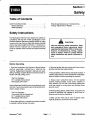
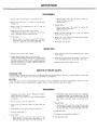
This safety symbol means DANGER, WARNING, or CAUTION, PERSONAL SAFETY
INSTRUCTION. When you see this symbol,
carefully read the instructions that follow.
Failure to obey the instructions may result in
personal injury.
NOTE: A NOTE will give general information about the
correct operation, maintenance, service, testing or repair of the machine.
IMPORTANT: The IMPORTANT notice will give important instructions which must be followed to prevent damage to systems or components on the
machine.
The Toro Company – 1991, 1998
Reelmaster 4500–D
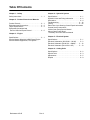
Table Of Contents
Chapter 1 – Safety
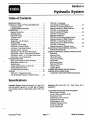
Chapter 4 – Hydraulic System
Safety Instructions . . . . . . . . . . . . . . . . . . . . . . . . . . 1 – 1
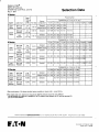
Specifications . . . . . . . . . . . . . . . . . . . . . . . . . . . . . . 4 – 1
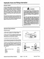
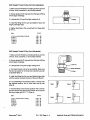
Hydraulic Hose and Fitting Information . . . . . . . . 4 – 2
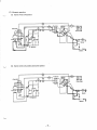
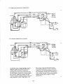
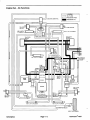
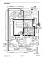
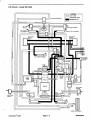
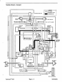
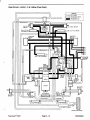
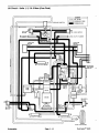
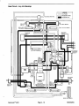
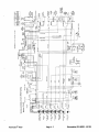
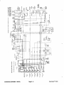
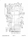
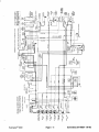
Schematics . . . . . . . . . . . . . . . . . . . . . . . . . . . . . . . . 4 – 4
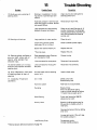
Troubleshooting . . . . . . . . . . . . . . . . . . . . . . . . . . . 4 – 16
Testing . . . . . . . . . . . . . . . . . . . . . . . . . . . . . . . . . . . 4 – 22
Eaton Char–Lynn Steering Control Repair Information
Cessna Service Instructions
Vickers Gear Pump Service Manual
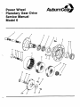
Auburn Gear Power Wheel
Planetary Gear Drive Service Manual
Chapter 2 – Product Records and Manuals
Product Records . . . . . . . . . . . . . . . . . . . . . . . . . . .
Equivalents and Conversions . . . . . . . . . . . . . . . .
Torque Specifications . . . . . . . . . . . . . . . . . . . . . . .
Equipment Operational and
Service Historical Report Record . . . . . . . . . . . .
2–1
2–2
2–3
2–5
Chapter 3 – Engine
Specifications . . . . . . . . . . . . . . . . . . . . . . . . . . . . . . 3 – 1
Service Manual, Mitsubishi 4DQ5 Diesel Engine
Service Manual Supplement, Fuel System
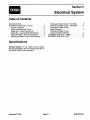
Chapter 5 – Electrical System
Specifications . . . . . . . . . . . . . . . . . . . . . . . . . . . . . . 5 – 1
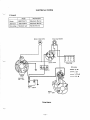
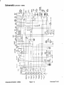
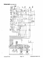
Electrical Schematics (S/N 60001 – 80100) . . . . 5 – 2
Electrical Schematic (S/N 80101 – 09999) . . . . 5 – 12
Electrical Schematic (S/N 10001 & UP) . . . . . . 5 – 13
Chapter 6 – Cutting Units
Specifications . . . . . . . . . . . . . . . . . . . . . . . . . . . . . .
Special Tools . . . . . . . . . . . . . . . . . . . . . . . . . . . . . .
Adjustments . . . . . . . . . . . . . . . . . . . . . . . . . . . . . . .
Repairs . . . . . . . . . . . . . . . . . . . . . . . . . . . . . . . . . . .
Reelmaster 450–D
Rev. A
6–2
6–3
6–5
6–9
Reelmaster 4500–D
Chapter 2
Product Records and Manuals
Table of Contents
PRODUCT RECORDS . . . . . . . . . . . . . . . . . . . . . . . . .
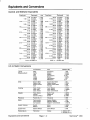
EQUIVALENTS AND CONVERSIONS . . . . . . . . . . .
Decimal and Millimeter Equivalents . . . . . . . . . . . .
U.S. to Metric Conversions . . . . . . . . . . . . . . . . . . .
1
2
2
2
TORQUE SPECIFICATIONS . . . . . . . . . . . . . . . . . . .
Capscrew Markings and Torque Values – U.S. . .
Capscrew Markings and Torque Values – Metric .
OPERATION AND SERVICE HISTORY REPORT .
3
3
3
5
Product Records
Record information about your Reelmaster 450–D on
the OPERATION AND SERVICE HISTORY REPORT
form. Use this information when referring to your machine.
Reelmaster 450–D
Insert Operator’s Manuals and Parts Catalogs for your
Reelmaster 450–D at the end of this section.
Page 2 – 1 Rev. A
Product Records and Manuals
This page is blank.
Product Records and Manuals
Page 2 – 4
Rev. A
Reelmaster 450–D
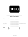
EQUIPMENT OPERATION AND SERVICE HISTORY REPORT
for
REELMASTER 450–D and 4500–D
TORO Model and Serial Number: ______________–______________
Engine Numbers:
_____________________________
Transmission Numbers:
_____________________________
Drive Axle(s) Numbers:
_____________________________
Date Purchased:
_____________________________ Warranty Expires____________
Purchased From:
_____________________________
_____________________________
_____________________________
Contacts:
Reelmaster 450–D
Parts
_____________________________ Phone____________________
Service
_____________________________ Phone____________________
Sales
_____________________________ Phone____________________
Page 2 – 5 Rev. A
Product Records and Manuals
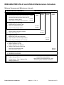
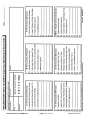
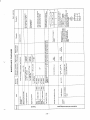
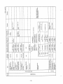
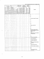
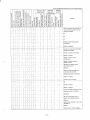
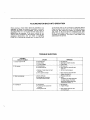
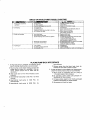
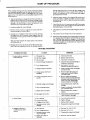
REELMASTER 450–D and 4500–D Maintenance Schedule
Minimum Recommended Maintenance Intervals
Every
50hrs
Lubricate Reel Control Valve Grease Fitting
Lubricate Reel Speed Control Valve with Oil
A Level
Lubricate all Grease Fittings
Check Battery Condition and Connections Service
Every
100hrs
Every
200hrs
Every
400hrs
Every
800hrs
} Change Engine Oil and Filter
Drain Water from Hydraulic Tank
{ Check Fan and Alternator Belt
Inspect Cooling System Hoses
B Level
Service
Service Air Cleaner Filter Element
C Level
Service
Inspect Cutting Unit Reel Drive Belts
{ Torque Wheel Lug Nuts
Replace Fuel Filter
Inspect Fuel Lines and Connections
} Torque Cylinder Head and Adjust Valves
D Level
Service
} Check Engine RPM (idle and full throttle)
Drain and Clean Fuel Tank
} Replace Hydraulic Oil Filter
Replace Hydraulic Tank Breather
} Change Front Planetary Gear Lube
Pack Rear Axle Bearings (2wd)
Check Rear Wheel Toe–In
E Level
Service
{ Initial break in at 10 hours
} Initial break in at 50 hours
Replace all Moving Hoses
Replace Safety Switches
Cooling System – Flush / Replace Fluid
Change Hydraulic Oil
Product Records and Manuals
Annual Recommendations:
Items listed are recommended every 1500
hours or 2 years, whichever occurs first.
Page 2 – 6
Rev. A
Reelmaster 450–D
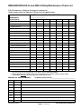
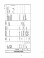
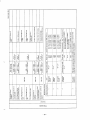
REELMASTER 450–D and 4500–D Daily Maintenance Check List
#/ %*%% +'# * * ) ' &( (&+* % +)
" '(&'( )* &% & '(*&() %+# &( #+ )' * &%)
Daily Maintenance Check For Week Of
_________________
Maintenance
Check Item b
MON
n
Safety Interlock Operation
n
Parking Brake Operation
n
Engine Oil Level
n
Fuel Level
n
Cooling System Fluid Level
TUES
WED
THURS
FRI
SAT
SUN
Drain Water/Fuel Separator
n
Dust Cup and Baffle (Air Filter)
n
Radiator & Screen for Debris1
Clean Traction Pedal Lockout
n
Unusual Engine Noises2
n
Unusual Operating Noises
n
Hydraulic System Oil Level
n
Hydraulic Hoses for Damage
n
Fluid Leaks
n
Tire Pressure
n
Instrument Operation
n
Warning Lamps Operation
n
Reel–to–Bedknife Adjustment
n
Height–of–Cut Adjustment
Lubricate All Grease Fittings3
Touch–up Damaged Paint
) &%#/ #&- '())+( &$'()) ( &( ( ) ($&,# " #&- '#+ % %!*&( %&00#) ( )*(* % .)) )$&" &( (&+ (+%% % ) %&*
$$ *#/ *( ,(/ -) % ((#)) & * %*(,# # )*
*$
*
%)'* &% '(&($ /
%&($* &%
Reelmaster 450–D
Page 2 – 7 Rev. A
Product Records and Manuals
Product Records and Manuals
Page 2 – 8
Rev. A
Reelmaster 450–D
This page is blank.
Chapter 6
Cutting Units
Table of Contents
SPECIFICATIONS . . . . . . . . . . . . . . . . . . . . . . . . . . . .
SPECIAL TOOLS . . . . . . . . . . . . . . . . . . . . . . . . . . . . .
ADJUSTMENTS . . . . . . . . . . . . . . . . . . . . . . . . . . . . . .
Adjusting Reel to Bedknife Contact . . . . . . . . . . . .
Height of Cut Adjustment (Floating Cutting Unit) .
Quick Method for Changing Height of Cut
After Initial Set Up of a Floating Cutting Unit . . .
Height of Cut Adjustment (Fixed Cutting Unit) . . .
Adjusting Skids and Front Roller
(Fixed Head Cutting Unit) . . . . . . . . . . . . . . . . . . . .
Reelmaster 450–D
2
3
5
5
6
REPAIRS . . . . . . . . . . . . . . . . . . . . . . . . . . . . . . . . . . . . 9
Backlapping . . . . . . . . . . . . . . . . . . . . . . . . . . . . . . . . 9
Hydraulic Motor Installation . . . . . . . . . . . . . . . . . . 10
Servicing the Bedknife/Bedbar Assembly . . . . . . 12
Servicing the Reel Assembly . . . . . . . . . . . . . . . . . 13
Roller Removal and Installation . . . . . . . . . . . . . . . 16
8
8
8
Page 6 – 1
Rev. A
Cutting Units
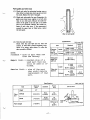
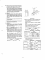
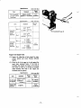
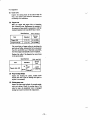
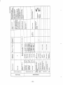
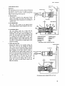
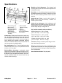
Specifications
Bedknife to Reel Adjustment: Two lockable lead
screw adjusters at each side of the frame adjust the reel
to bedknife contact.
Rear Roller: 3–1/2 in. (89 mm) diameter steel roller has
greaseable tapered roller bearings. A double lip oil seal
and wear sleeve isolates grit and moisture from the
bearings.
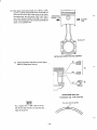
Height–of–Cut: 5 Blade – 1 to 3 in. (25 to 76 mm). 7
Blade – 1/2 to 1–3/4 in. (9.5 to 45 mm). 1 1 Blade – 3/8
to 3/4 in. (9.5 to 19 mm).
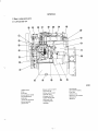
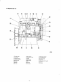
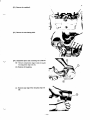
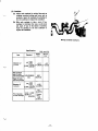
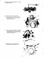
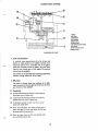
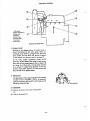
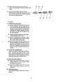
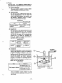
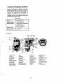
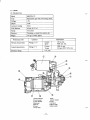
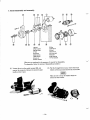
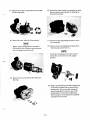
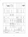
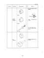
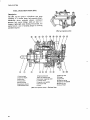
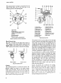
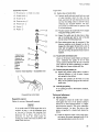
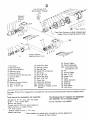
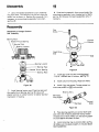
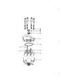
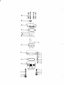
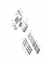
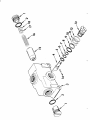
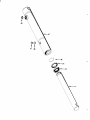
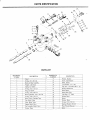
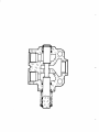
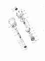
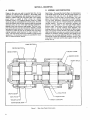
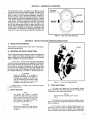
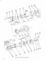
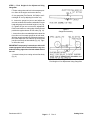
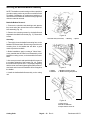
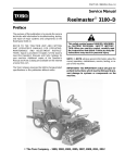
Figure 1
1. Drive housing cover
2. Drive housing
3. Reel motor fasteners,
drive plate shield and
shipping cover
4. Grass deflector
5. Rear roller adjusting
assembly
6. Reel to bedknife
adjusting assembly
7. Guard
8. Cone nut
9. Reel assembly
10. Front roller (optional)
11. Top covers
Construction: Welded steel frame and reel with heavy
duty, self–aligning ball bearings. Heavy duty steel rear
roller with tapered roller bearings. Rear roller and bedbar are isolated and mounted in rubber bushings for
quiet, vibration–free operation. Adjustable deflector
shields are standard. Stainless steel components are
used at key points for added durability.
Reel Configuration: The 5, 7 and 11 blade heavy duty
welded reels all have 8 in. (20.3 cm) diameters and are
29–3/4 in. (75.5 cm) wide.
Bedknife/Bedbar Assembly: A replaceable, single
edged, alloy steel bedbar is induction hardened. It’s fastened with steel screws to a precision ground surface on
the high strength, fabricated steel bedbar. The stress–
relieved machined bedbar is mounted with four (4)
vibration isolation bushings.
Cutting Units
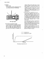
Height–of–Cut Adjustment: Quick adjustment and
positive locking is provided by locking type cone nuts.
Gauge marks of 1/4 in. (6.3 mm) are provided as a reference for easy changes of height–of–cut.
Clip (variable to match cutting conditions):
5 Blade Cutting Unit: .176 in. per mph
(.352 in. at 2 mph – 1.32 in. at 7.5 mph)
7 Blade Cutting Unit: .1 26 in. per mph
(.252 in. at 2 mph – .945 in. at 7.5 mph)
11 Blade Cutting Unit: .080 in. per mph
(.16 in. at 2 mph – .600 in. at 7.5 mph)
Lubrication: Easily accessible grease fittings for bearings and all major pivot points.
Drive: The reel drive motor turns a maintenance–free
cog belt which drives the reel. Drive pulley and cog belt
are encased in a drive housing for safety and protection
from contamination.
Grass Deflector Shields: Fully Adjustable.
Page 6 – 2
Rev. A
Reelmaster 450–D
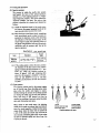
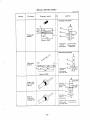
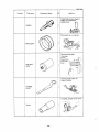
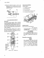
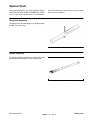
Special Tools
Order special tools from the TORO SPECIAL TOOLS
AND APPLICATIONS GUIDE (COMMERCIAL PRODUCTS). Some tools may be listed in the Reelmaster
4500–D Parts Catalog. Some tools may also be available from a local supplier.
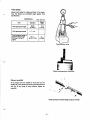
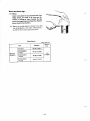
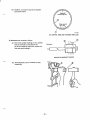
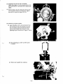
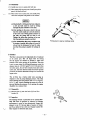
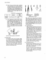
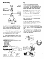
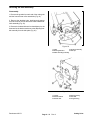
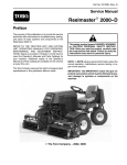
Gauge Bar Assembly
Use gauge bar to set final height of cut (floating cutting
unit with front roller only).
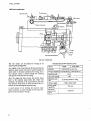
Figure 2
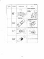
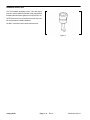
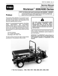
Handle Assembly
For applying lapping compound to cutting units while
keep hands a safe distance from the rotating reel.
Figure 3
Reelmaster 450–D
Page 6 – 3
Rev. A
Cutting Units
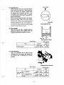
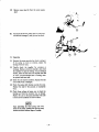
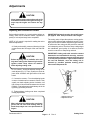
Bedknife Screw Tool
Fits Toro bedknife attaching screws. Use with torque
wrench to secure bedknife to bedbar. With clean bedbar
threads and new screws, tighten to a torque of 250 in–lb.
NOTE: Remove all rust, scale and corrosion from bedbar surface before installing bedknife.
DO NOT use and air impact wrench with this tool.
Figure 4
Cutting Units
Page 6 – 4
Rev. A
Reelmaster 450–D
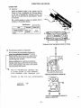
Adjustments
CAUTION
Never install or work on the cutting units or lift
arms with the traction unit engine running. Always stop the engine and remove the key
first.
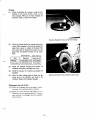
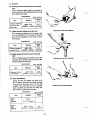
Adjusting Reel to Bedknife Contact
Before adjusting height–of–cut and each day before operating, check reel to bedknife contact, regardless if
quality of cut had previously been acceptable.
NOTE: A 3/4” wrench is required for making the reel to
bedknife adjustment.
A. Slowly and carefully rotate reel,listening for light
contact across the full length of the reel and bedknife.
IMPORTANT: Adjusted correctly, the reel will cut paper (approx. .003” thick) across its entire length.
The cutting units will provide optimum mowing performance when adjusted and maintained correctly. Keeping a precise reel to bedknife adjustment (light contact),
at each end of the cutting unit will produce a continual
self–sharpening action. Therefore, sharp cutting edges
are maintained, good quality of cut assured, and the
need for corrective re–sharpening reduced.
IMPORTANT: Cutting units with excessive contact
between the reel and bedknife are noisy, consume
excessive power, shorten component life and result
in overall poor performance. Light contact between
the reel and bedknife, once the cutting unit is
warmed up, provides optimum mowing performance and component life.
CAUTION
Before adjusting reel to bedknife, raise and
fully latch cutting units. Remove key from the
ignition switch. Keep others off machine
while adjusting cutting units.
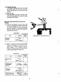
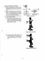
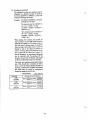
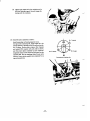
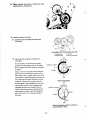
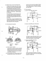
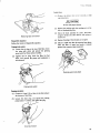
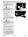
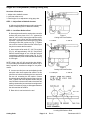
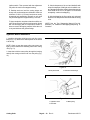
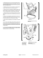
B. If no contact – loosen the adjuster locking nut on
each adjuster (Fig. 5). Then, equally turn each adjuster knob clockwise until light contact is felt and
heard.
C. If excessive contact – Turn the adjusting knobs
counter–clockwise until no contact is noticed. Then
equally turn both adjusting knobs clockwise, until
light contact is felt and heard between the reel and
bedknife. Final adjustment should always be in the
tightening (clockwise) direction.
D. Tighten adjuster locking nuts when completed
making adjustments.
Figure 5
1. Adjuster locking nut
2. Adjustment knob
CAUTION
When adjusting the cutting units, wear heavy
gloves and use care when turning reels by
hand. Sharp edges can cut or pinch hands or
fingers.
Reelmaster 450–D
Page 6 – 5
Rev. A
Cutting Units
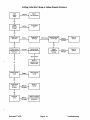
Height–of–Cut Adjustment (Floating Cutting Unit)
Overview of Procedure:
1. Adjust reel to bedknife contact
2. Level rear roller to reel
3. Final height–of–cut adjustment using gauge bar.
STEP 1 – Adjust Reel to Bedknife Contact
A. Adjust reel to bedknife contact on all cutting units.
(Refer to Adjusting Reel To Bedknife Contact).
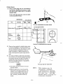
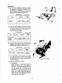
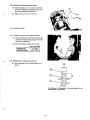
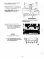
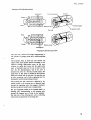
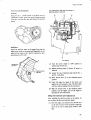
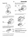
STEP 2 – Level Rear Roller to Reel
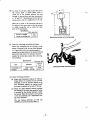
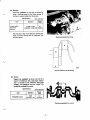
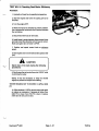
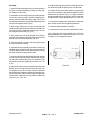
B. Start engine and lower the cutting units onto a flat
surface such as a piece of 3/4” or 1” plywood (at
least 20” x 30” in size). Stop engine and remove key
from switch. Lock cutting units in the fixed position,
by loosen—ing the jam nut on lockout pin (Fig. 6) and
screwing pin into hole in pivot arm (Fig. 7). Tighten
nut to secure lockout. Raise the front rollers up so
they do not contact the flat surface.
Figure 6
Cutting Unit Float Position
1. Lockouts
2. Jam nut
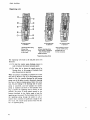
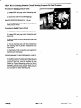
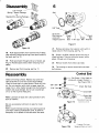
C. Insert a piece of bar stock 25” – 28” (70 cm) long
(Fig. 8), and approximately 3/8” (9.5 mm) thicker
than the desired height–of–cut, under the reel and
up against the bedknife cutting edge (Fig. 8). The
reel (not bedknife) must contact the bar stock along
its full length.
NOTE: Using a bar 3/8” (9.5 mm) thicker than height–
of–cut provides proper bedknife attitude (heeled ”up” in
back) required for excellent low height–of–cut performance.
D. Loosen rear roller jam nuts and adjusting knobs
and push roller down against flat surface. At this
point the reel should contacting the bar stock and
the rear roll contacting the flat surface. Contact
should exist along the entire length of the reel a rear
roller. Tighten rear roller adjustme knobs and jam
nuts. Recheck to be sure roller and reel are both still
making contact after jam nuts have been tightened.
Check roll contact by trying to slide paper between
the roller and the flat surface.
Figure 7
Cutting Unit Fixed Position
1. Lockout pin
2. Jam nut
E. Rear roller is now leveled to the reel.
HOC + 3/8”
Figure 8
Leveling Rear Roller to Reel
Cutting Units
Page 6 – 6
Rev. A
Reelmaster 450–D
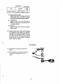
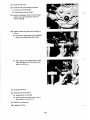
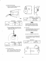
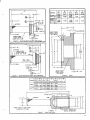
STEP 3 – Final Height–of–Cut Adjustment Using
Gauge Bar
F. Raise cutting units and lock in the transport position. Shut off the engine and remove the key.
G. Use gauge bar (Toro Part No. 59–7900) to set final height–of–cut by adjusting front roller only.
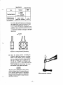
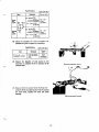
H. Loosen the gauge bar jam nut and adjust the
screw to set dimension between underside of screw
head and gauge bar for desired height–of–cut (Fig.
9). Tighten the jam nut to secure the adjustment.
Hook screw head over cutting edge of bedknife and
position bar against bottom of front roller (Fig. 10).
Figure 9
Gauge Bar Assembly
I. Loosen front roller nuts and adjust both ends of the
front roller until it contacts gauge bar at both ends.
With the gauge bar held firmly against the bottom of
the rollers adjust the front roller so the screw head
just slips over the lip of the bedknife (Fig. 10). Tighten front roller nuts.
3/8”
IMPORTANT: Set properly, front and rear rollers will
contact gauge bar and screw head will be snug over
bedknife cutting edge when checked at both ends of
the reel.
J. Loosen lockout pin so cutting unit can float freely
(Fig. 6).
Figure 10
Final Height–of–Cut Adjustment Using Gauge Bar
Reelmaster 450–D
Page 6 – 7
Rev. A
Cutting Units
Quick Method For Changing Height–of–Cut After Initial Set Up of a Floating Cutting Unit
If the reel to bedknife adjustment has been set (STEPÿ1)
and the rear roller leveled to the reel (STEP 2), the cutting unit may be quickly changed from one height–of–
cut to another by using the gauge bar (Part #59–7900)
and adjusting the front roller only. In many cases, an entire machine can be done quickly by using the gauge bar
to set the front roller of one cutting unit. The remaining
cutting units can then be set by loosening their front roller jam nuts and turning each front roller adjustment knob
the same number of turns and in the same direction as
the first unit.
Height–of–Cut Adjustment (Fixed Cutting Unit)
1. Adjust reel to bedknife contact.
2. Loosen nuts securing skids or front roller and raise to
highest position.
3. Loosen jam nuts securing rear roller. Lower roller beyond desired height–of–cut (assures proper bedknife
attitude).
3/8”
4. Lower cutting unit onto a flat surface, such as a 1” x
20” x 30” piece of plywood. Shut off engine and remove
the key.
5. Insert piece of bar stock (Fig. 11) 25”–28” (70 cm) long
with thickness equal to desired height–of–cut, under entire length of the reel, next to bedknife.
Figure 11
6. Adjust rear roller adjustment knobs and jam nuts until
full length of the rear roller contacts the flat surface and
the full length of the reel (not bedknife) contacts the bar
stock. Tighten rear roller knobs and jam nuts.
Adjusting Skids and Front Roller (Fixed Head Cutting Unit)
After skid kit or front rollers are installed (installation
instructions are included with each option) make the following adjustments to prevent them from pushing down
uncut grass or scalping on undulating terrain:
1. Lock each cutting unit in the fixed position (Refer to
Cutting Unit Orientation, Fig. 15. Set the reel to bedknife
adjustment and height–of–cut adjustment.
2. Position the cutting units on a flat, level surface (a 1”
inch (25 mm) thick piece of plywood is ideal).
3. Skids and front rollers used to prevent scalping should
not ride on the ground. Adjust each skid or front roller so
it is 1/8 – 1/4 in. (3 – 6 mm) or higher above the level surface. Allow greater clearance at the higher height–of–
cut settings.
4. Proper adjustment is achieved when the cutting unit
does not scalp the grass in normal mowing conditions
and yet is set high enough not to mar the turf and create
undue wear on the skids or rollers.
NOTE: Skids are used only with the cutting unit in the
fixed position. Front rollers may be used with the cutting
unit in either the fixed or floating position.
Cutting Units
Page 6 – 8
Rev. A
Reelmaster 450–D
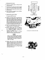
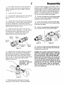
Repairs
CAUTION
Never install or work on the cutting units or lift
arms with the traction unit engine running. Always stop the engine and remove the key
first.
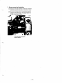
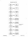
Backlapping
the #2 and #3 cutting units from the front of the machine.
CAUTION
C. Wait for 2nd person’s instruction to engage reels
in BACKLAP mode, then pull up on reel switch and
move it to ENGAGE position.
DURING BACKLAP OPERATION REELS ARE
UNDER POWER. CONTACT WITH ROTATING
REELS CAN RESULT IN PERSONAL INJURY.
DO NOT ADJUST CUTTING UNITS WHILE ENGINE AND REELS ARE OPERATING.
INSTRUCT OPERATOR TO STOP THE REELS
AND SHUT THE ENGINE OFF WHEN ADJUSTMENT IS NECESSARY.
D. Turn REEL SPEED KNOB counterclockwise to
the BACKLAP position.
E. Follow 2nd person’s instructions. Be prepared to
stop reels and engine quickly in case of an emergency.
2nd persons duties:
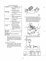
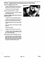
Use a good grade of medium grit (80 courseness) lapping compound with a water soluble carrier so the compound will be easily washed away after completion of
the operation. Dry lapping compound should be mixed
with liquid detergent until it has a free–flowing consistency.
Two people are required to perform backlapping. Good
communication between one another is necessary and
caution should be used when making each move. With
one person on the seat to operate the controls (operator) the other performs the backlapping operation.
NOTE: Before starting the engine raise the grass deflector on the #1 cutting unit (center) and tighten fasteners
to retain the deflector in the raised position.
1st persons duties (Operator):
A. Sit on the seat and engage parking brake.
B. Start the engine and run at minimum throttle.
Lower either:1.) the center cutting unit (#1) or2.) the
left hand (#2) cutting unit or3.) the right hand (#3)
cutting unit.
With the #2 & # 3 cutting units up and latched (automatically shut off) and the #1 cutting unit down,
backlap the center (#1) cutting unit from the rear of
the machine with the long handled brush. Backlap
Reelmaster 450–D
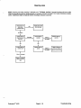
A. Instruct operator when to start and stop reels.
CAUTION
UNDER NO CIRCUMSTANCES USE A
SHORT–HANDLED PAINT BRUSH TO APPLY
BACKLAPPING COMPOUND. A ROTATING
REEL CAN ACTUALLY PULL A SHORT HANDLED PAINT BRUSH AND THE USERS HAND
INTO THE REEL CAUSING SERIOUS PERSONAL INJURY.
B. Dip 3 in. (76 mm) paint brush attached to Toro
Part No. 29–9200 Handle Assembly into lapping
compound. Stand clear and instruct operator to engage reel into backlap mode.
C. Apply lapping compound evenly over full length
of the reel, assuring that all reel blades are covered.
Whenever noise of reel against the bedknife begins
to disappear or, an uneven concentration of material
appears on the reel, redistribute the compound with
the brush.
D. When it becomes necessary to adjust the reel to
the bedknife, instruct the operator to disengage the
reel, stop the engine and remove the key from the
Cutting Units
Page 6 – 9 Rev. A
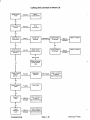
G. Check sharpness of the reel and bedknife with
strips of newspaper. With light reel to bedknife contact, the paper should be cleanly sheared across the
entire width of the reel. If the paper is not sheared
acceptably, continue backlapping.
ignition switch. Then proceed with the adjustment
only after the reels have stopped rotating.
E. Backlap each reel until the cutting edges are
sharp, even, and consistent on all blades. Achieve a
minimum of 1/32 in. (0.79 mm) land area on newly
sharpened reel assemblies. Normally, a reel need
only be backlapped for approximately 3 minutes.
F. Upon completion, stop the reel and turn off the engine. Remove the key from the ignition switch. Wash
the unit thoroughly with a low pressure stream of
water to remove all lapping material. Allow the reel
to dry and lubricate the grease fittings.
H. After backlapping the first cutting unit, raise and
latch this unit and proceed with the #2 and #3 cutting
units.
NOTE: See the Toro Sharpening Manual (Part No.
80300SL) for additional backlapping/sharpening information.
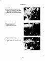
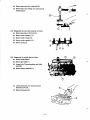
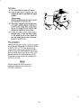
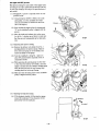
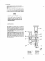
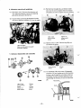
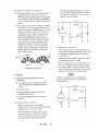
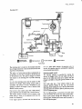
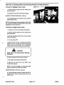
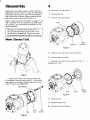
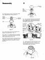
Hydraulic Motor Installation
1. Install the drive plate shield onto the reel drive motor
flange (Fig. 12). Be sure the widest portion of the shield
is at the top.
NOTE: Check to see that motor pulley set screws are
tight on motor shaft before installing motor onto cutting
unit (Fig. 13).
2. Insert the reel drive motor pulley through the housing
and slip the cutting unit drive belt over the pulley (Fig.
13).
Figure 12
1. Drive plate shield
2. Reel drive motor flange
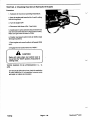
Figure 13
1. Hydraulic motor
3. Drive belt
Cutting Units
Page 6 – 10
Rev. A
2. Motor pulley
Reelmaster 450–D
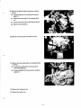
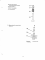
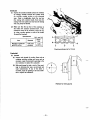
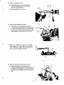
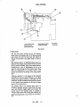
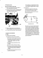
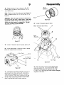
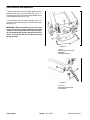
3. Insert the two (2) reel drive motor mounting bolts
(heads on inside of the drive housing – flat washer on top
bolt) through the reel motor flange holes. Thread the
locknuts onto the bolts. Rotate reel motor upward in the
slotted hole in the housing to tension the drive belt and
tighten the fasteners (Fig. 14) to approx. 25 ft–lbs (34
Nm). NOTE: Proper belt tension is achieved when belt
deflects approximately 1/8” (3 mm) at mid–point when
7 lbs. force is applied. (Fig. 14).
IMPORTANT: Rotate motors by hand only. Never
place a bar between hose fittings on hydraulic motors – motor damage may result.
Figure 14
4. Install the gasket and drive housing cover after making sure the ends of the gasket are at the bottom of the
housing to allow for drainage.
1. Reel motor fasteners
1. #3 Cutting unit
2. Hose bracket
IMPORTANT: When hydraulic motors have been
mounted to the cutting units make sure hydraulic
hoses lay flat and do not contact the frame of the
machine when the cutting units are in the raised
position. There should also be sufficient slack SO
hoses are above and not in contact with the floatation kit. If hoses appear twisted once the hydraulic
motors have been mounted and the belts tightened,
loosen swivel nuts at the motor and reposition
hoses. This can greatly increase the life of the
hoses. With cutting units down, all cutting unit
hoses should have a flat natural lay and be free from
twist.
NOTE: Refer to the Traction Unit Operator’s Manual for
instructions on setting the adjustable hydraulic counterbalance.
Reelmaster 450–D
Page 6 – 11
Rev. A
Cutting Units
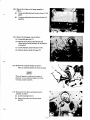
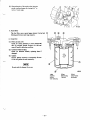
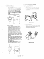
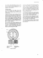
Servicing the Bedknife/Bedbar Assembly
NOTE: The bedbar on each cutting unit has a precision
ground mounting surface to provide an excellent fit with
a bedknife. Backlapping of replacement bedknives is
often sufficient to achieve an excellent cutting edge with
minimum material removed.
Bedknife/Bedbar Removal:
1. Remove the shoulder bolts,bushings and spacers
from each end of the unit and remove the bedbar/bedknife assembly (Fig. 16).
2. Remove the mounting screws for the bedknife and
separate the bedknife from the bar (Fig. 17). Discard the
screws.
Figure 16
1. Shoulder bolts (2 each side)
Assembly:
2. Bushing
3. Spacer
1. Thoroughly clean the bedknife mounting face on the
bedbar of all rust and scale. Remove any material on the
mounting face of the bedbar that will affect a good
match–up with the bedknife.
2. Before installation, apply a coating of ”Never Seez”,
or any material that will ease future disassembly of the
bedknife mounting screws, to the threads before installation.
3. Use a torque wrench and special bedknife screw tool
to complete tightening of the screws (Fig. 18). Tighten
the screws to a torque of 250 in.–lb (28 Kgm) beginning
with the center screw and tightening alternate screws toward each end to insure the bedknife will be flat against
the bedbar.
4. Install the bedbar/bedknife assembly to the cutting
unit.
Figure 17
1. Bedbar
2. Bedknife
3. Bedknife mounting screws
4. Bedbar mounting components
Figure 18
1. Torque wrench
2. Part No. 51–0880 Tool
3. Torque from the center out
Cutting Units
Page 6 – 12
Rev. A
Reelmaster 450–D
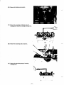
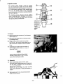
Servicing the Reel Assembly
Disassembly:
1. Remove the guards from each end of the cutting unit
and the front and rear roller assemblies (Fig. 19).
2. Remove the shoulder bolts, bushings and spacers
from each end of the unit and remove the bedbar/bedknife assembly (Fig. 20).
3. Remove the inboard locknut from the adjuster pin, the
fasteners for the bracket and remove the adjusting handle assembly from the side plate (Fig. 20).
Figure 19
1. Guard
4. Adjusting assembly
2. Mounting fasteners
5. Dust cap
3. Bedbar mounting assembly
Figure 20
1. Locknut
2. Belleville washer
3. Shoulder bolt
Reelmaster 450–D
Page 6 – 13 Rev. A
4. Bearing housing
5. Reel shaft
6. Flange bushing
Cutting Units
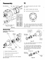
4. Disassemble the cone nut from the shoulder bolt securing the bearing housing to the side plate, remove the
belleville washer and bolt and slide the bearing housing
off the reel shaft (Fig. 21).
5. Disassemble the cover from the drive housing and remove the drive belt from the housing (Fig. 22).
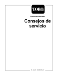
6. Remove the reel capscrew, toothed washer and
pulley washer from the reel shaft (Fig. 22). (Note: Capscrew is assembled with a thread locking compound).
7. Using a puller,remove the driven pulley from the reel
shaft (Fig. 22). Remove the woodruff key from the reel
shaft.
8. Remove the adjustment assembly and cone nut,
belleville washer and shoulder bolt securing the housing
to the side plate (Fig. 22). Remove the housing.
Figure 21
9. Slide the reel assembly out of the slots in the side
plates.
1. Drive housing (cover removed)
2. Drive belt
10. To remove the bearing and seals from the drive
housing, remove the retaining ring from inside the housing. Pry the outer seal out of the belt drive case side.
Press the bearing and rear seal out from the outer side
of the housing.
11. To remove the bearing and seal from the bearing
housing, remove the dust cap (Fig. 19) and press the
bearing and seal out of the housing.
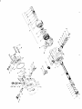
Figure 22
1. Reel capscrew
2. Pulley washer
3. Driven pulley
4. Drive housing
Cutting Units
Page 6 – 14
Rev. A
5. Adjustment handle assembly
6. Woodruff key
7. Drive housing fasteners
Reelmaster 450–D
9. Install the woodruff key in the drive housing end of the
reel shaft and install the driven pulley onto the shaft.
Assembly:
1. Inspect the flange bushings in the mounting holes for
the drive housing and bearing housing for wear (Fig.
20). Replace, if necessary.
2. Assemble the outer seal (lip facing in to retain grease)
into the drive housing using Loctite 242 retaining compound on the outer diameter. Apply a light coat of oil to
the seal lips and insert the bearing assembly through the
seal from the opposite side (Fig 23).
3. Apply a light coating of oil to the inner seal lips and
install (lip facing away from the bearing and toward the
reel) in the housing. Install the retaining ring to secure
the assembly in the housing (Fig. 23).
4. Apply a light coat of oil to the seal lips of the seal for
the bearing housing and install (lip facing away from the
bearing) over the bearing assembly (Fig. 23).
10. Ensure the slot in the pulley washer is aligned with
the roll pin in the pulley and install the washer, toothed
washer and reel capscrew (Fig. 21). Apply a medium
strength thread locking compound to the reel capscrew
during assembly. Torque the capscrew to 45 – 55 ft.–lbs.
11. Install the reel adjustment assemblies to each side
plate. Install roll pins before tightening fasteners.
12. Install the bedbar/bedknife assembly.
13. Install the front and rear roller assemblies or skids.
14. To adjust the reel to the bedknife; refer to Reel to
Bedknife Adjustment. To adjust the height–of–cut; refer
to Height–of–Cut Adjustment section.
5. Insert the bearing and seal in the housing and install
the dust cap into the housing.
6. Assemble the reel assembly to the frame. Ensure the
shield washer is installed on the drive housing end of the
reel shaft. Align drive pin on reel shaft with slot in bearing
and slide the drive housing onto the shaft.
7. Insert the shoulder bolt through the Belleville washer
and rear housing mounting hole. Slide the bolt through
the side plate mounting hole (Fig. 20). Install the cone
nut locknut onto the bolt. Tighten the cone nut to 45 – 55
ft.–lbs.
8. Align the drive pinon the reel shaft with the notch in the
bearing inner race and slide the bearing housing over
the opposite end of the reel shaft. Insert the shoulder
bolt and belleville washer through the rear bearing housing mounting hole. Slide the bolt through the side plate
mounting hole. Install the cone onto the bolt. Tighten the
cone nut to 45 – 55 ft.–lbs.
Reelmaster 450–D
Page 6 – 15 Rev. A
Figure 23
Cutting Units
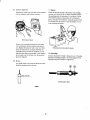
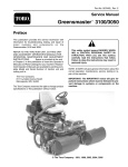
Roller Removal and Installation
1. Remove the fasteners securing the guard and roller
adjustment housing to the side plate (Fig. 24) or unscrew the upper cone nut and drop the threaded rod out
of the adjustment housing (Fig. 25).
2. The threaded rod and collar assembly can be removed from the roller by sliding it off the shaft at both
ends (Fig. 25).
IMPORTANT: When assembling a new roller to the
cutting unit mount the roller so that the roller shaft
”locknut” is on the right side of the cutting unit (Fig.
25). (As viewed by the operator sitting on seat of machine). This prevents the lock nut from loosening
during operation.
Figure 24
1. Guard
2. Roller adjustment housing
3. Side plate
4. Mounting fasteners
Figure 25
1. Cone nut
2. Rod and collar assembly
3. Flex locknut
Cutting Units
Page 6 – 16
Rev. A
Reelmaster 450–D
Commercial Products
The Toro Company – 1995