1
Part No. 96876SL Rev. A
Service Manual
Reelmaster 2300–D/2600–D
Preface
The purpose of this publication is to provide the service
technician with information for troubleshooting, testing,
and repair of major systems and components on the
Reelmaster 2300–D/2600–D.
REFER TO THE TRACTION UNIT AND CUTTING
UNIT OPERATOR’S MANUALS FOR OPERATING,
MAINTENANCE AND ADJUSTMENT INSTRUCTIONS. Space is provided in Chapter 2 of this book to
insert the Operator’s Manuals and Parts Catalogs for
your machine. Replacement Operator’s Manuals are
available by sending complete Model and Serial Number to:
The Toro Company
8111 Lyndale Avenue South
Minneapolis, MN 55420
The Toro Company reserves the right to change product
specifications or this publication without notice.
This safety symbol means DANGER, WARNING, or CAUTION, PERSONAL SAFETY
INSTRUCTION. When you see this symbol,
carefully read the instructions that follow.
Failure to obey the instructions may result in
personal injury.
NOTE: A NOTE will give general information about the
correct operation, maintenance, service, testing, or repair of the machine.
IMPORTANT: The IMPORTANT notice will give important instructions which must be followed to prevent damage to systems or components on the
machine.
The Toro Company – 1996, 1998
This page is blank.
Chapter 2 – Product Records and Manuals
Product Records . . . . . . . . . . . . . . . . . . . . . . . . . . .
Equivalents and Conversions . . . . . . . . . . . . . . . .
Torque Specifications . . . . . . . . . . . . . . . . . . . . . . .
Maintenance Interval Chart . . . . . . . . . . . . . . . . . .
Operation and Service History Report . . . . . . . . .
2–1
2–2
2–3
2–4
2–5
Chapter 3 – Engine
Introduction . . . . . . . . . . . . . . . . . . . . . . . . . . . . . . . .
Specifications . . . . . . . . . . . . . . . . . . . . . . . . . . . . . .
Special Tools . . . . . . . . . . . . . . . . . . . . . . . . . . . . . .
Adjustments . . . . . . . . . . . . . . . . . . . . . . . . . . . . . . .
Service and Repairs . . . . . . . . . . . . . . . . . . . . . . . .
Perkins 100 Series Workshop Manual
3–2
3–3
3–4
3–7
3–9
4 – 16
4 – 17
4 – 19
4 – 34
4 – 37
Chapter 5 – Electrical System
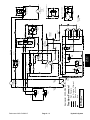
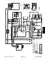
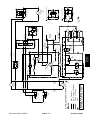
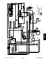
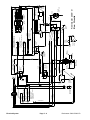
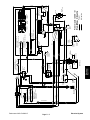
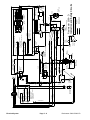
Wiring Schematics . . . . . . . . . . . . . . . . . . . . . . . . . 5 – 2
Special Tools . . . . . . . . . . . . . . . . . . . . . . . . . . . . . . 5 – 9
Troubleshooting . . . . . . . . . . . . . . . . . . . . . . . . . . . 5 – 10
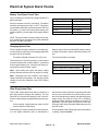
Electrical System Quick Checks . . . . . . . . . . . . . 5 – 15
Component Testing . . . . . . . . . . . . . . . . . . . . . . . . 5 – 17
Service and Repairs . . . . . . . . . . . . . . . . . . . . . . . 5 – 27
Chapter 6 – Wheels and Brakes
Specifications . . . . . . . . . . . . . . . . . . . . . . . . . . . . . . 6 – 2
Adjustments . . . . . . . . . . . . . . . . . . . . . . . . . . . . . . . 6 – 3
Service and Repairs . . . . . . . . . . . . . . . . . . . . . . . . 6 – 4
Product Records
and Manuals
Safety Instructions . . . . . . . . . . . . . . . . . . . . . . . . . . 1 – 1
Safety and Instruction Decals . . . . . . . . . . . . . . . . 1 – 4
Special Tools . . . . . . . . . . . . . . . . . . . . . . . . . . . . .
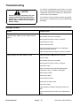
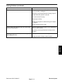
Troubleshooting . . . . . . . . . . . . . . . . . . . . . . . . . . .
Testing . . . . . . . . . . . . . . . . . . . . . . . . . . . . . . . . . . .
Adjustments . . . . . . . . . . . . . . . . . . . . . . . . . . . . . .
Service and Repairs . . . . . . . . . . . . . . . . . . . . . . .
Engine
Chapter 1 – Safety
Safety
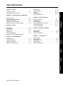
Table Of Contents
Chapter 7 – Cutting Units
4–2
4–3
4–7
4–8
Specifications . . . . . . . . . . . . . . . . . . . . . . . . . . . . . . 7 – 2
Special Tools . . . . . . . . . . . . . . . . . . . . . . . . . . . . . . 7 – 3
Trouble Shooting . . . . . . . . . . . . . . . . . . . . . . . . . . . 7 – 5
Adjustments . . . . . . . . . . . . . . . . . . . . . . . . . . . . . . . 7 – 7
Service and Repairs . . . . . . . . . . . . . . . . . . . . . . . 7 – 11
Cutting Units
Wheels and
Brakes
Electrical
System
Specifications . . . . . . . . . . . . . . . . . . . . . . . . . . . . . .
General Information . . . . . . . . . . . . . . . . . . . . . . . .
Hydraulic Schematic . . . . . . . . . . . . . . . . . . . . . . . .
Hydraulic Flow Diagrams . . . . . . . . . . . . . . . . . . . .
Hydraulic
System
Chapter 4 – Hydraulic System
Reelmaster 2300–D/2600–D
This page is blank.
Chapter 1
Safety
Safety
Table of Contents
SAFETY INSTRUCTIONS . . . . . . . . . . . . . . . . . . . . . . 1
Before Operating . . . . . . . . . . . . . . . . . . . . . . . . . . . . 1
While Operating . . . . . . . . . . . . . . . . . . . . . . . . . . . . 2
Maintenance and Service . . . . . . . . . . . . . . . . . . . . 3
SAFETY AND INSTRUCTION DECALS . . . . . . . . . . 4
Safety Instructions
The REELMASTER 2300–D/2600–D conforms to the
American National Standards Institute’s (ANSI) safety
standards for riding mowers when equipped with rear
ballast (see Operator’s Manual). Although hazard control and accident prevention are partially dependent
upon the design and configuration of the machine, these
factors are also dependent upon the awareness, concern, and proper training of the personnel involved in the
operation, transport, maintenance, and storage of the
machine. Improper use or maintenance of the machine
can result in injury or death.
WARNING
To reduce the potential for injury or death,
comply with the following safety instructions.
Before Operating
Improper use or maintenance by the operator or owner
of the machine can result in injury. Reduce the potential
for any injury by complying with the following safety instructions.
Use the Model and Serial Number when referring to your
machine. If you have questions about this Service
Manual, please contact:
The Toro Company
Commercial Service Department
8111 Lyndale Avenue South
Minneapolis, Minnesota 55420–1196
WARNING
The engine exhaust contains carbon
monoxide, which is an odorless and
deadly poison. Carbon monoxide is also
known to the state of California to cause
birth defects. Do not run engine indoors
or in an enclosed area.
2. Only trained operators, skilled in slope operation
and who have read the Operator’s Manual, should operate the machine. Never allow children to operate the
machine or adults to operate it without proper instructions.
1. Read and understand the contents of the traction
unit and cutting unit operator’s manuals before operating the machine. To get replacement manuals, send
complete model and serial number to:
3. IMPORTANT: Always use proper rear ballast as
specified in the operator’s manual (see Rear Ballast of
the Operator’s Manual).
4. Become familiar with the controls and know how to
stop the machine and engine quickly.
The Toro Company
8111 Lyndale Avenue South
Minneapolis, Minnesota 55420–1196
Reelmaster 2300–D/2600–D
Page 1 – 1
Safety
5. Do not carry passengers on the machine. Keep everyone, especially children and pets, away from the areas of operation.
6. Keep all shields, safety devices and decals in place.
lf a shield, safety device or decal is damaged, malfunctioning or illegible, repair or replace it before operating
the machine.
9. Make sure the work area is clear of objects which
might be picked up and thrown by the reels.
10. Fill the fuel tank with diesel fuel before starting the
engine. Avoid spilling any fuel. Since fuel is highly flammable, handle it carefully.
A. Use an approved fuel container.
B. Do not remove the cap from the fuel tank when
engine is hot or running.
7. Always wear substantial shoes. Do not operate machine while wearing sandals, tennis shoes or sneakers.
Do not wear loose fitting clothing because it could get
caught in moving parts and possibly cause personal injury.
C. Do not smoke while handling diesel fuel.
D. Fill fuel tank outdoors and not over one inch from
the top of the tank, (bottom of the filler neck). Do not
overfill.
8. Wearing safety glasses, safety shoes, long pants
and a helmet is advisable and required by some Iocal ordinances and insurance regulations.
While Operating
F. Stay alert for holes in terrain and other hidden
hazards. Use extreme care when operating close to
sand traps, ditches, creeks, steep hillsides or other
hazards.
11. Do not run the engine in a confined area without adequate ventilation. Exhaust fumes are hazardous and
could be deadly.
12. Sit on the seat when starting and operating the machine.
G. Reduce speed when making sharp turns. Avoid
sudden stops and starts. Use reverse pedal for
braking. The cutting units must be lowered when
going down slopes for steering control.
13. Check interlock switches daily for proper operation
(see Checking Interlock Switches of the Operator’s
Manual). Do not rely entirely on safety switches; shut off
engine before getting off the seat. If a switch fails, replace it before operating the machine. The interlock system is for your protection, so do not bypass it. Replace
all interlock switches every two years.
14. When starting the engine:
A. Engage parking brake.
B. Be sure traction pedal is in neutral and reel drive
is in the disengage position.
C. After the engine starts, release parking brake
and keep foot off the traction pedal. The machine
must not move. If movement is evident, the neutral
control linkage is incorrectly adjusted: therefore,
shut engine off and adjust until the machine does
not move when the traction pedal is released (see
Adjusting Transmission for Neutral of the Operator’s Manual).
D. Hills over 15 degrees should be mowed up and
down, not side to side (see Slope Gauge of the Operator’s Manual).
E. Mowing hills may be dangerous. Hills over 20
degrees should not be mowed (see Slope Gauge of
the Operator’s Manual).
Safety
H. Before backing up, look to the rear and assure
that no one is behind the machine. Watch out for
traffic when near or crossing roads. Always yield the
right of way.
15. Keep hands, feet, and clothing away from moving
parts and the reel discharge area. Grass baskets, if so
equipped, must be in place during reel operation for
maximum safety.
16. This product may exceed noise levels of 85 dB(A)
at the operator position. Ear protectors are recommended for prolonged exposure to reduce the potential
of permanent hearing damage.
17. Raise the cutting units when driving from one work
area to another.
18. Do not touch engine, muffler, exhaust pipe, or hydraulic tank while engine is running or soon after it has
stopped. These areas could be hot enough to cause
burns.
19. If a cutting unit strikes a solid object or vibrates abnormally, stop cutting unit immediately. Turn the engine
off, wait for all motion to stop and inspect for damage.
A damaged or bedknife must be repaired or replaced before operation is continued.
Page 1 – 2
Reelmaster 2300–D/2600–D
20. Before getting off the seat:
D. Stop the engine and remove the key from the ignition switch.
A. Move the traction pedal to neutral.
B. Set the parking brake.
Safety
C. Disengage the cutting units and wait for the reels
to stop spinning.
21. Whenever the machine is left unattended, make
sure the reels are not spinning, the key is removed from
ignition switch, and the parking brake is set.
Maintenance and Service
22. Before servicing or making adjustments to the machine, stop the engine and remove the key from the
switch to prevent accidental starting of the engine.
23. When changing attachments, tires or performing
other service, use the correct blocks, hoists and jacks.
Always chock or block the wheels and use jack stands
or solid wood blocks to support the raised machine. If
the traction unit is not properly supported by blocks or
jack stands, the unit may move or fall resulting in personal injury.
24. Check performance of all interlock switches daily.
Do not defeat interlock system. It is for your protection.
25. Ensure the entire machine is in good operating
condition. Frequently check and keep all nuts, bolts,
screws, and hydraulic fittings tight.
26. Before applying pressure to the hydraulic system,
make sure all hydraulic line connectors are tight and all
hydraulic hoses and lines are in good condition .
27. Keep body and hands away from pin hole leaks or
nozzles that eject hydraulic fluid under high pressure.
Use paper or cardboard, not hands, to search for leaks.
Hydraulic fluid escaping under pressure can have sufficient force to penetrate the skin and cause serious injury. lf fluid is injected into the skin, it must be surgically
removed within a few hours by a doctor familiar with this
form of injury or gangrene may result.
Reelmaster 2300–D/2600–D
28. Before disconnecting or performing any work on the
hydraulic system, all pressure in system must be relieved by stopping the engine and lowering cutting units
to the ground.
29. If major repairs are ever needed or if assistance is
desired, contact an Authorized Toro Distributor.
30. Reduce potential fire hazards. Keep the engine
area free of excessive grease, grass, leaves, and accumulation of dirt.
31. If the engine must be running to perform a maintenance adjustment, keep hands, feet, clothing, and any
other parts of the body away from the cutting units and
any moving parts. Keep everyone away.
32. Do not overspeed the engine by changing governor
settings. To assure safety and accuracy, have an Authorized Toro Distributor check maximum engine speed
with a tachometer.
33. The engine must be shut off before checking oil or
adding oil to the crankcase.
34. To insure optimum performance and safety, use
genuine TORO replacement parts and accessories. Replacement parts and accessories made by other manufacturers could be dangerous, and such use could void
the product warranty of The Toro Company.
Page 1 – 3 Rev. A
Safety
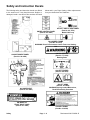
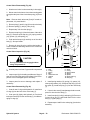
Safety and Instruction Decals
The following safety and instruction decals are affixed
to the traction unit. If any decal becomes illegible or
damaged, install a new decal. Part numbers are listed
below and in your Parts Catalog. Order replacements
from your Authorized Toro Distributor.
UNDER CONTROL PANEL
(Part No. 93–6902)
ON LEFT SIDE OF SEAT PANEL
(Part No. 92–7270)
Model 03427 only
ON CARRIER FRAME
(Part No. 94–3353)
WARNING! Pinch Point between Carrier Frame and Cutting
Unit
ON FAN SHROUD
(Part No. 77–3100)
ON INSTRUMENT PANEL
(Part No. 94–4985)
Rotating Parts
ON LEFT FENDER
(Part No. 84–1650)
ON LIFT ARMS
(Part No. 93–6696)
WARNING! Spring Loaded Mechanism,
Read Disassembly Procedure
ON UNDER SEAT
(Part No. 93–6903)
ON INSIDE OF
FRONT RIGHT PANEL
(Part No. 67–5360)
Safety
ON SKIRT PANEL
(Part No. 83–9550)
Page 1 – 4
Reelmaster 2300–D/2600–D
&))!% # !## *) %( % )
"*()$%) '&*'(
Reelmaster 2300–D/2600–D
Page 1 – 5
Safety
') & Safety
Safety
Page 1 – 6
Reelmaster 2300–D/2600–D
Chapter 2
Product Records and Manuals
PRODUCT RECORDS . . . . . . . . . . . . . . . . . . . . . . . . .
EQUIVALENTS AND CONVERSIONS . . . . . . . . . . .
Decimal and Millimeter Equivalents . . . . . . . . . . . .
U.S. to Metric Conversions . . . . . . . . . . . . . . . . . . .
1
2
2
2
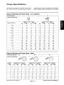
TORQUE SPECIFICATIONS . . . . . . . . . . . . . . . . . . .
Capscrew Markings and Torque Values – U.S. . .
Capscrew Markings and Torque Values – Metric
MAINTENANCE INTERVAL CHART . . . . . . . . . . . . .
OPERATION AND SERVICE HISTORY REPORT .
3
3
3
4
5
Product Records
Record
information
about
your
Reelmaster
2300–D/2600–D on the OPERATION AND SERVICE
HISTORY REPORT form. Use this information when referring to your machine.
Reelmaster 2300–D/2600–D
Insert Operator’s Manuals and Parts Catalogs for your
Reelmaster 2300–D/2600–D at the end of this section.
Page 2 – 1
Product Records and Manuals
Product Records
and Manuals
Table of Contents
Equivalents and Conversions
Product Records and Manuals
Page 2 – 2
Reelmaster 2300–D/2600–D
Product Records
and Manuals
Torque Specifications
Reelmaster 2300–D/2600–D
Page 2 – 3
Product Records and Manuals
Maintenance Interval Chart
Product Records and Manuals
Page 2 – 4
Reelmaster 2300–D/2600–D
Product Records
and Manuals
EQUIPMENT OPERATION AND SERVICE HISTORY REPORT
for
REELMASTER 2300–D/2600–D
TORO Model and Serial Number: _____________–___________
Engine Numbers:
_________________________
Transmission Numbers:
_________________________
Date Purchased:
_________________________
Purchased From:
_________________________
Warranty Expires___________
_________________________
_________________________
Contacts:
Parts
_________________________
Phone___________________
Service
_________________________
Phone___________________
Sales
_________________________
Phone___________________
See your TORO Distributor for other Publications, Manuals, and Videos from the TORO company.
Reelmaster 2300–D/2600–D
Page 2 – 5
Product Records and Manuals
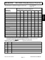
REELMASTERR
2300–D/2600–D Maintenance Schedule
Minimum Recommended Maintenance Intervals:
Maintenance Procedure
Inspect Air Filter, Dust Cup, and Baffle
Lubricate All Grease Fittings
{ Change Engine Oil
{ Check Fan and Alternator Belt Tensions
Maintenance Interval & Service
Every
100hrs
Every
50hrs
Every
200hrs
Every
400hrs
A–Level
Service
{ Change Engine Oil and Filter
B–Level
Service
{ Check Traction Belt Tension
Service Air Filter
Replace Fuel Filter/Water Separator
{ Replace Hydraulic Filter
C–Level
Service
{ Torque Wheel Lug Nuts
*
Replace Hydraulic Fluid
Check Battery Level/Connections
Inspect Traction Linkage Movement
Inspect Spider Coupling for Wear
D–Level
Service
} Torque Head Bolts and Adjust Valves
} Check Engine RPM (idle and full throttle)
{ Initial break in at 10 hours
* Every 400 hours or annually, whichever occurs first
} Initial break in at 50 hours
Replace all Moving Hoses
Replace Safety Switches
Cooling System – Flush/Replace Fluid
Replace Thermostat
Fuel Tank – Drain/Flush
Hydraulic Tank – Drain/Flush
Annual Recommendations:
Items listed are recommended every 1000 hours
or 2 years, whichever occurs first.
(See Operator’s and Service Manuals for specifications and procedures.)
Product Records and Manuals
Page 2 – 6
Reelmaster 2300–D/2600–D
REELMASTERR
2300–D/2600–D Daily Maintenance Check List
Unit Designation: ____________
Daily Maintenance: (duplicate this page for routine use)
TORO ID #: ________–________
Daily Maintenance Check For Week Of ________________
n
Safety Interlock Operation
n
Brake Operation
n
Engine Oil Level1
n
Cooling System Fluid Level1
MON
TUES
WED
THURS
FRI
SAT
SUN
________HRS
________HRS
________HRS
________HRS
________HRS
________HRS
________HRS
Product Records
and Manuals
Maintenance
Check Item b
Drain Water/Fuel Separator
n
Air Filter, Dust Cup, and Baffle
n
Radiator & Screen for Debris
n
Unusual Engine Noises2
n
Unusual Operating Noises
n
Hydraulic System Oil Level1
n
Hydraulic Hoses for Damage
n
Fluid Leaks
n
Fuel Level1
n
Tire Pressure
n
Instrument Operation
n
Reel–to–Bedknife Adjustment
n
Height–of–Cut Adjustment
Lubricate All Grease Fittings3
Touch–up Damaged Paint
1=
2=
3=
Check proper section of Operator’s Manual for fluid specifications.
Check glow plug and injector nozzles, if hard starting, excess smoke or rough running is noted.
Accomplish immediately after every washing, regardless of the interval listed.
Notation for areas of concern:
Item
Date
Inspection performed by:__________________
Information
1
2
3
4
5
6
7
(See Operator’s and Service Manuals for specifications and procedures.)
Reelmaster 2300–D/2600–D
Page 2 – 7
Product Records and Manuals
Product Records and Manuals
Page 2 – 8
Reelmaster 2300–D/2600–D
R
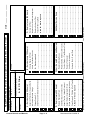
A B C D Other
Service to perform (circle):
__________________–__________________
TORO I.D. #:
_______________________________
_______________________________
________________________________
________________________________
Coolant System – Flush/Replace Fluid
Replace Thermostat
Fuel Tank – Drain/Flush
Hydraulic Tank – Drain/Flush
_______________________________
_______________________________
_______________________________
Inspect Traction Linkage Movement
Inspect Spider Coupling for Wear
Torque Head Bolts and Adjust Valves
Check Engine RPM (Idle & Full Throttle)
A, B, and C – Sevice required
________________________________
________________________________
(See Operator’s and Service Manual for specifications and procedures.)
Replace Safety Switches (Every 2 yrs)
Replace Moving Hoses
Check Battery Level/Connections
Replace Hydraulic Fluid
Other – Annual Service and Specials
_______________________________
________________________________
D – Service (every 400 hours)
_______________________________
_______________________________
Check Fan and Alternator Belt Tension
________________________________
A – Service required
Change Engine Oil
_______________________________
Check Traction Belt Tension
Lubricate All Grease Fittings
________________________________
Change Engine Oil Filter
B – Service (every 100 hours)
Inspect Air Filter, Dust Cup, and Baffle
A– Service (every 50 hours)
Technician:
Hours:
Unit Designation:
Remarks:
________________________________
________________________________
________________________________
________________________________
________________________________
________________________________
________________________________
________________________________
________________________________
Additional Service Items
________________________________
________________________________
________________________________
________________________________
A and B – Sevice required
Torque Wheel Lug Nuts
Replace Hydraulic Filter
Replace Fuel Filter/Water Separator
Service Air Filter
C – Service (every 200 hours)
Date: ________________
Form No. 95–872–SL
2300–D/2600–D Supervisor Maintenance Work Order
(Duplicate this page for routine use.)
REELMASTER
Chapter 3
Engine
Table of Contents
2
3
4
6
6
7
7
8
SERVICE AND REPAIRS . . . . . . . . . . . . . . . . . . . . . . 9
Bleeding the Fuel System . . . . . . . . . . . . . . . . . . . . 9
Air Cleaner . . . . . . . . . . . . . . . . . . . . . . . . . . . . . . . . 10
Cleaning the Radiator and Screen . . . . . . . . . . . . . 11
Changing the Engine Oil and Filter . . . . . . . . . . . 12
Checking the Cooling System . . . . . . . . . . . . . . . . 12
Engine Removal . . . . . . . . . . . . . . . . . . . . . . . . . . . 13
Engine Reinstallation . . . . . . . . . . . . . . . . . . . . . . . 18
PERKINS 100 SERIES WORKSHOP MANUAL
Engine
INTRODUCTION . . . . . . . . . . . . . . . . . . . . . . . . . . . . . .
SPECIFICATIONS . . . . . . . . . . . . . . . . . . . . . . . . . . . .
SPECIAL TOOLS . . . . . . . . . . . . . . . . . . . . . . . . . . . . .
GENERAL INFORMATION . . . . . . . . . . . . . . . . . . . . .
Fuel Shutoff Valves . . . . . . . . . . . . . . . . . . . . . . . . . .
ADJUSTMENTS . . . . . . . . . . . . . . . . . . . . . . . . . . . . . .
Alternator Belt . . . . . . . . . . . . . . . . . . . . . . . . . . . . . .
Throttle Linkage . . . . . . . . . . . . . . . . . . . . . . . . . . . .
Reelmaster 2300–D/2600–D
Page 3 – 1
Engine
Introduction
This Chapter gives information about specifications,
maintenance, troubleshooting, testing, and repair of the
diesel engine used in the Reelmaster 2300–D/2600–D
mower.
Most repairs and adjustments require tools which are
commonly available in many service shops. Special
tools are described in the Special Tools section. The use
of some specialized test equipment is explained. How-
Engine
ever, the cost of the test equipment and the specialized
nature of some repairs may dictate that the work be
done at an engine repair facility.
Service and repair parts for Perkins engines are supplied through your local Perkins/Detroit Diesel dealer. If
no parts list is available, be sure to provide your dealer
or distributor with the Perkins model and serial number.
Page 3 – 2
Reelmaster 2300–D/2600–D
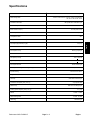
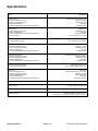
Specifications
Item
Description
Make / Designation
Perkins, vertical in–line, 4–stroke, water–cooled Diesel,
103–07 KL 70275 & KL 70372
Combustion Chamber
IDI special swirl–combustion type
Number of Cylinders
3
Bore x Stroke mm (in.)
67 x 64 (2.64 x 2.52)
Total Displacement cc (cu. in.)
676 (41.23)
Compression Ratio
24:1
Firing Order
1– 2–3
64 (141)
Fuel
Grade No. 2D diesel fuel (ASTM specification)
Fuel Injection Pump
Bosch type plunger
Governor
Mechanical
Idle Speed (no load)
1400 + 50 RPM
High Idle (no load)
3200 + 50 RPM
Fuel Injector Nozzle
Bosch throttle type
Fuel Injection Working Pressure kg/cm2 (psi)
115 to 125 (1636 to 1778)
Injection Timing
28.5 to 30.5 B.T.D.C.
Engine Oil
SAE 10W30 SF, CD
Oil Pump
Gear driven trochoid type
Crankcase Oil Capacity liter (U.S. qt.)
2.8 (3.0) with filter
Water Pump
Belt driven centrifugal type
Cooling System Capacity liter (U.S. qt.)
4.7 (5.0)
Starter
12 VDC 1.2 KW
Alternator/Regulator
12 VDC 14 AMP
Glow Plug
Reelmaster 2300–D/2600–D
Sheathed type
Page 3 – 3
Engine
Engine
Dry Weight (approximate) kg (lb.)
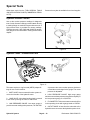
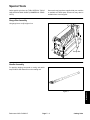
Special Tools
Order special tools from TORO SPECIAL TOOLS AND
APPLICATIONS GUIDE (Commercial Products).
Some tools may be listed in the Reelmaster
2300–D/2600–D Parts Catalog. Tools may also be
available from a local supplier.
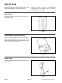
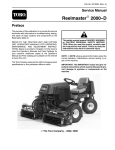
Filter Cleaner
Mix with water and use solution to wash the Donaldson
air cleaner element.
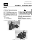
Figure 1
Diesel Engine Compression Test Kit
This 0 to 1000 PSI gauge allows testing of diesel engines for checking the general operating condition of the
engine. The kit includes a case, gauge with hose, glow
plug hole adapters, and instructions.
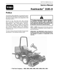
Figure 2
Nozzle Tester
This tests the condition and opening pressure of fuel injection nozzles.
Figure 3
Engine
Page 3 – 4
Reelmaster 2300–D/2600–D
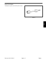
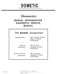
Nozzle Test Adapter
This adapter is required to test the fuel injection nozzles.
Engine
Figure 4
Reelmaster 2300–D/2600–D
Page 3 – 5
Engine
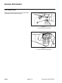
General Information
Fuel Shutoff Valves
These valves should be shut when removing the engine
or placing the unit in long term storage.
1
Figure 5
1. Fuel shut off (under the fuel tank)
1
Figure 6
1. Fuel shut off valve (on the fuel filter)
Engine
Page 3 – 6
Reelmaster 2300–D/2600–D
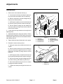
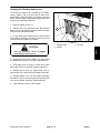
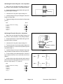
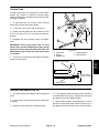
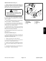
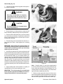
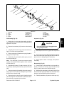
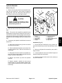
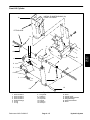
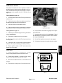
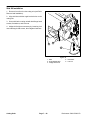
Adjustments
Alternator Belt
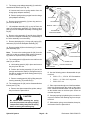
1. Gain access to the alternator belt (Fig 7).
A. Loosen top hose clamp securing the upper portion of the hose connected to the air cleaner (8).
8
6
3
B. Remove cap screws (1) and lock flange nuts (2).
Remove hex head screws (3).
1
C. On European models, remove hex head screws
(4) from the guard (5) and air cleaner housing (6).
D. Pull air cleaner housing from the radiator top
shroud (7) and hose. Plug air cleaner hose and hose
inlet to the air cleaner.
4
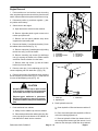
2. Loosen bolts securing alternator to the engine and
adjusting strap.
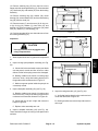
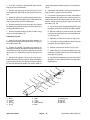
3. Adjust alternator belt to the proper tension. Tension
alternator belt so it deflects 0.20 inch with a 2 to 3 pound
load applied midway between the crankshaft and alternator pulleys (Fig. 8).
4. Tighten bolts securing the alternator to the engine.
7
3
2
1
Figure 7
1.
2.
3.
4.
Cap screw
Lock flange nut
Hex head screw
Hex head screw
5.
6.
7.
8.
Guard (Europe)
Air cleaner housing
Radiator top shroud
Air cleaner
5. Reinstall air cleaner housing (Fig 7).
A. Unplug air cleaner hose and hose inlet to the air
cleaner.
B. Place air cleaner housing (6) on the radiator top
shroud (7). Reconnect upper end of the air cleaner
hose to the air cleaner (8). Align holes to receive
fasteners.
1
C. On European models, reinstall hex head screws
(4) into guard (5) through the air cleaner housing (6).
D. Secure cap screws (1) and lock flange nuts (2) to
air cleaner housing and radiator top shroud (7).
E. Secure hex head screws (3) into the air cleaner
housing and radiator assembly.
Figure 8
1. Engine belt
F. Tighten hose clamp securing the hose to the air
cleaner.
Reelmaster 2300–D/2600–D
Page 3 – 7
Engine
Engine
5
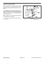
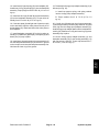
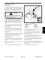
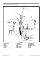
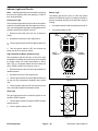
Throttle Linkage
1. Verify high engine speed at 3200 50 RPM with
the cold start button depressed.
2. If engine speed is out of specification, loosen cap
screw, nut, and throttle cable clamp on the throttle cable
bracket enough to allow the cable to slide freely within
the bracket.
3. Move throttle lever up fully to the high speed position.
1
4. Pull cable toward flywheel end of the engine until the
governor lever on the engine is up against the high
speed adjustment screw. Tighten cap screw and nut securing the throttle cable clamp.
5. Loosen capscrews (1) and nuts (2) securing the
throttle stop (3).
2
6. With the cold start button depressed, carefully adjust low engine speed to 1400 50 RPM with the
throttle control lever (4); adjust low speed stop screw
if necessary.
4
3
Figure 9
7. Make sure throttle control lever (4) is down so the
governor lever on the engine touches the low speed adjustment screw.
1. Cap screw
2. Nut
3. Throttle stop
4. Throttle control leve
8. Adjust throttle stop (3) until it contacts the bottom of
the throttle control lever (4). Tighten cap screws (1) and
nuts (2) securing the throttle stop.
9. Make sure governor lever on the engine goes
against the high speed adjustment screw when the
throttle control lever (4) is moved to the high speed position. When the throttle control lever is moved to the low
speed position, the governor lever on the engine should
contact the low speed adjustment screw at the same
time the throttle control lever contacts the throttle stop
(3).
Engine
Page 3 – 8
Reelmaster 2300–D/2600–D
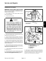
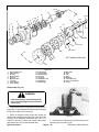
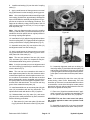
Service and Repairs
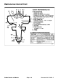
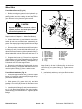
Bleeding the Fuel System
IMPORTANT: The fuel system must be primed
when a new or rebuilt engine is started for the first
time, if it runs out of fuel, or if maintenance is performed on the fuel system.
1. Park machine on a level surface. Make sure fuel
tank is at least half full.
2
2. Unlatch and raise hood.
1
3
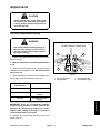
DANGER
Figure 10
1. Fuel shutoff valve
2. Bleed screws
3. Bowl
6
Engine
Because diesel fuel is flammable, use
caution when storing or handling it. Do
not smoke while filling the fuel tank. Do
not fill the fuel tank while the engine is
hot, running, or when the in an enclosed
area. Always fill the fuel tank outside.
Wipe up any spilled diesel fuel before
starting the engine. Store fuel in a clean
safety–approved container with its cap
on. Use diesel fuel for the engine only
and no other purpose.
1
5
4
3. Open fuel shutoff valve (1) located under the fuel
tank and on the fuel filter (Fig. 10).
4. Open both bleed screws (2) located on the side of
the fuel filter mounting head. Allow bowl (3) to refill with
fuel. Close bleed screws when the bowl is filled (Fig. 10).
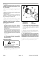
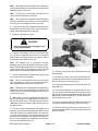
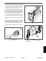
5. On the front of the engine by the oil filter, find transfer pump inlet screw location (2). Note fitting angle (5)
on the transfer pump inlet and loosen left transfer pump
screw (1) only (Fig. 11).
6
Figure 11
6. When a steady stream of fuel flows out of the transfer pump screw (1), tighten screw and retain noted fitting
angle (5) from step 5 above (Fig. 11).
1.
2.
3.
4.
5.
6.
7. Loosen injection pump inlet screw (3) on the front of
the engine (Fig. 11).
8. Pump priming lever (4) until a steady stream of fuel
flows out of injection pump inlet screw (3), then tighten
screw. Do not over tighten inlet screw (Fig. 11).
Reelmaster 2300–D/2600–D
3
2 Transfer pump screw
Transfer pump inlet screw location
Injection pump inlet screw
Priming lever
Note fitting angle
Injector nut
9. Start engine. If engine does not run smoothly after
several minutes, crack open each injector nut (6) until
fuel (with no bubbles) comes out. Torque each injector
nut from 14.4 to 18.0 ft–lb (2.0 to 2.5 kg–m).
Page 3 – 9
Engine
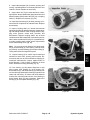
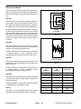
Air Cleaner
1. Service the air cleaner filter every 400 hours (more
frequently in extreme dusty or dirty conditions). Do not
over service air filter.
4
2. Check air cleaner body (1) for damage which could
possibly cause an air leak. Replace damaged air cleaner body.
3
ÇÇ
ÇÇ
ÇÇ
3. Make sure air cleaner cover (2) is sealing around
the air cleaner body (1).
4. Release latches (3) securing the air cleaner cover
(2) to the air cleaner body (1). Separate cover from
body. Clean inside of air cleaner cover.
1
2
5. Gently slide filter element (4) out of the air cleaner
body (1) to reduce the amount of dust dislodged. Avoid
knocking filter element against air cleaner body.
6.Inspect filter element (4) and discard if damaged. Do
not wash or reuse a damaged filter.
Washing Method
Figure 12
1. Air cleaner body
2. Air cleaner cover
3. Latch
4. Filter element
A. Prepare a solution of filter cleaner and water.
Soak filter element (4) in the solution for 15 minutes.
Refer to directions on filter cleaner carton for complete information.
B. Keep air hose nozzle at least 2 inches from the
filter element (4). Move nozzle up and down while
rotating the filter element. Inspect for holes and
tears by looking through the filter element toward a
bright light.
B. After soaking filter element (4) for 15 minutes,
rinse it with clear water. Maximum water pressure
must not exceed 40 psi to prevent damage to the filter element. Rinse filter element from the clean side
to the dirty side.
7. Inspect new filter element (4) for shipping damage.
Check sealing end of new or used filter element. Do not
install a damaged filter element.
C. Dry filter element (4) using warm flowing air
(160F maximum), or allow element to air–dry. Do
not use a light bulb to dry the filter element because
damage could result.
8. Insert filter element (4) properly into the air cleaner
body (1). Make sure filter element is sealed properly by
applying pressure to the outer rim of the filter element
when installing. Do not press on the flexible center of the
filter element.
9. Reinstall air cleaner cover (2) and secure latches
(3). Make sure cover is positioned with top side up.
Compressed Air Method
CAUTION
Use eye protection such as goggles
when using compressed air.
A. Blow compressed air from the inside to the outside of the dry filter element (4). Do not exceed 100
psi to prevent damage to the filter element.
Engine
Page 3 – 10
Reelmaster 2300–D/2600–D
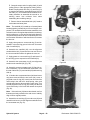
Cleaning the Radiator and Screen
To prevent the engine from overheating, the radiator
screen, radiator, and oil cooler must be kept clean.
Check these components daily. If necessary, clean any
debris off these parts. Clean these components more
frequently in dusty dirty conditions.
1
1. Remove radiator screen (1).
2. Remove four cap screws and nuts that hold the
plastic cover to the radiator assembly. Remove plastic
cover from the radiator assembly.
3
3. Loosen both quick release knobs on the front end
of the radiator assembly. Now the oil cooler (3) can be
removed from the radiator for cleaning.
2
Figure 13
1. Radiator screen
2. Radiator
3. Oil cooler
Engine
CAUTION
Use eye protection such as goggles
when using compressed air.
4. Working from fan side of radiator (2), either spray
the radiator with a hose or blow with compressed air.
5. Thoroughly clean oil cooler (3). Clean off any other
debris that may have collected around components.
6. Reinstall the oil cooler (3). Tighten both quick release knobs on the front end of the radiator assembly.
7. Reinstall plastic cover onto the radiator assembly.
Reinstall four cap screws and nuts that hold the plastic
cover to the radiator assembly. Tighten fasteners
8. Clean radiator screen (1) and reinstall.
Reelmaster 2300–D/2600–D
Page 3 – 11
Engine
Changing the Engine Oil and Filter
Change oil and filter initially after the first 20 hours of operation. Thereafter, change oil every 50 hours and filter
every 100 hours.
1
1. Position machine on a level surface.
2. Locate engine oil drain plug on the bottom of oil pan
and place a collecting pan below it. Remove drain plug
and let oil flow into the collecting pan. When the oil stops
draining, install drain plug.
Figure 14
3. Locate engine filter on the front of the engine. Remove oil filter. Apply a light coat of clean oil to the new
filter seal before screwing it on. DO NOT OVERTIGHTEN.
Note: The crankcase capacity is approximately 2.8
qts. (3.0 L) with filter. The engine uses any high–quality
10W30 detergent oil having the American Petroleum Institute – API – “service classification” CD.
1. Oil fill cap
1
4. Add oil to the crankcase.
A. Remove oil fill cap (Fig. 14) and gradually add
small quantities of oil .
Figure 15
1. Dipstick
B. Check oil level frequently until the level reaches
the FULL mark on dipstick (Fig 15). When removing
the dipstick, wipe it with a clean rag prior to inserting
it to check the oil level.
C. Push dipstick down into dipstick tube and make
sure it is seated fully when finished (Fig 15).
Checking the Cooling System
"("# " &# "$# &*
#! !# #( ( #!) % # # # ( !
"#!# # #( # "("#
" !'#( $!#" 1
CAUTION
If the engine has been running, pressurized hot coolant or steam can escape
when the radiator cap is removed. Burns
may result. Do not open radiator cap
when the radiator or engine is hot.
1.
Figure 16
1. Radiator cap
3. # # % " & !" # "("# DO
NOT OVERFILL
!$( !% !#! 2.
% # # !#! !#! #
# # !)# ! Engine
4. "# !#! ##
Page 3 – 12
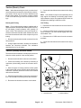
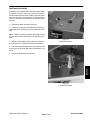
Reelmaster 2300–D/2600–D
Engine Removal
1. Park machine on a level surface, lower the cutting
units, stop the engine, and remove the key from the start
switch. Chock wheels to keep the machine from moving.
3
3
5
1
2. Disconnect positive (+) and then negative (–) battery cables at the battery.
3
3. Gain access to the engine.
A. Open and remove hood from the machine.
3
B. Remove right side panel to gain access to the
traction pump drive belt.
4
C. Remove left rear panel (radiator side) which
supports the instrument panel.
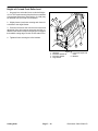
A. Remove cap screw (3) and flange nut (4) holding
the left foot rest (5) to the left fender.
B. Remove remaining cap screws (3) and flange
nuts (4) securing the fender to the fender bracket
and frame. Remove fender from the frame.
6
4
3
4
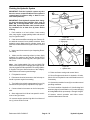
Figure 17
1. Left fender
2. Left fender bracket
3. Cap screw
C. Remove both cap screws (3) and left fender
bracket (2) from the frame.
Engine
4. Remove left fender (1) and fender bracket (2) from
the radiator side of the frame (Fig. 17).
2
4. Flange nut
5. Left footrest
6. Clinch nut
2
3
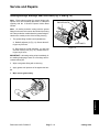
5. Remove cotter pin (1) from adjusting rod (2). Disconnect adjusting rod from brake arm (3) (Fig. 18).
1
6. Remove cap screws (3) and flange nut (4) securing
the left footrest (5) to the frame (Fig. 17). Slide the left
foot rest off the adjusting rod (2) (Fig. 18).
CAUTION
DO NOT open radiator cap or drain coolant
if the engine or radiator is hot. Pressurized
hot coolant can escape and cause burns.
Figure 18
Ethylene–gycol antifreeze is poisonous.
Dispose of it properly or store it in a properly labeled container away from children and
pets.
1. Cotter pin
2. Adjusting rod
3. Brake arm
8. Drain hydraulic reservoir.
A. Clean hydraulic oil filter and area around the filter.
7. Drain antifreeze from radiator.
A. Slowly remove radiator cap from the radiator.
B. Place drain pan below the radiator pipe plug. Remove pipe plug from the bottom of the radiator. Allow antifreeze to drain into the container
Reelmaster 2300–D/2600–D
Page 3 – 13
B. Place clean drain pan below hydraulic oil filter to
collect the draining hydraulic oil.
C. Remove hydraulic oil filter from bottom of the filter housing with a bottom type filter wrench. Let oil
drain into the drain pan; install filter when drained.
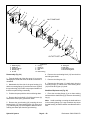
Engine
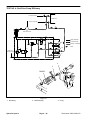
RIGHT
39
11
1
2
4
36
5
32
13
6
7
9
8
44
10
CONNECTED TO
AIR FILTER HOSE
19
11
38
19
12
41
14
45
3
15
23
18 19
25
16
17
40
39
29
11
31
30 37
20 21
43
26
35
23
25
7
28
34
42
34
36
FRONT
22 LH
46 RH
24
33
13
LEFT
27
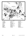
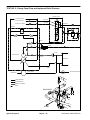
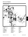
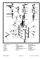
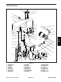
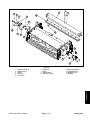
Figure 19
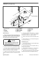
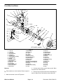
1.
2.
3.
4.
5.
6.
7.
8.
9.
10.
11.
12.
13.
14.
15.
16.
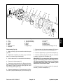
Cap screw
Lock washer
Clutch washer
Engine pulley
Cap screw
Wire bracket
Nut
Pop rivet
Key
Cap screw
Flat washer
R–clamp
Washer
Muffler
Muffler tube
Muffler bracket
Engine
17.
18.
19.
20.
21.
22.
23.
24.
25.
26.
27.
28.
29.
30.
31.
U–bolt
Upper radiator hose
Muffler clamp
Nut
Lock washer
Left rear mount bracket
Hose clamp
Lower radiator hose
Engine
Throttle cable clamp
Flange nut
Throttle cable bracket
Clevis pin
Cotter pin
Throttle tab
Page 3 – 14
32.
33.
34.
35.
36.
37.
38.
39.
40.
41.
42.
43.
44.
45.
46.
Flat washer
Lock washer
Front mount bracket
Insert nut
Cap screw
Clutch spindle
Hose clamp
Cap screw
Electric clutch
Cap screw
Cap screw
Cap screw
Fuel hose
Muffler gasket
Right rear mount bracket
Reelmaster 2300–D/2600–D
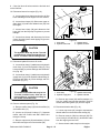
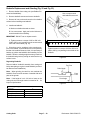
9. Close fuel shut–off valves under the fuel tank and
on the fuel filter.
10. Disconnect hoses from engine (Fig. 19).
2
4
A. Loosen upper hose clamp securing the air filter
hose extending from the engine to the air cleaner.
B. Loosen hose clamps (23). Disconnect upper radiator hose (18) and lower radiator hose (24) from
the engine.
C. Loosen hose clamp (38) and disconnect fuel
hose (44) from the lift pump. Plug hose to prevent
leakage.
1
3
D. Loosen hose clamp and disconnect fuel hose
(return) from the injector nozzle piping. Plug hose to
prevent leakage.
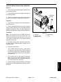
Figure 20
1. Hose clamp
2. Hydraulic return hose
3. Hydraulic fitting
4. Hydraulic reservoir
2
The hydraulic fluid may be hot. To avoid
possible burns, allow the hydraulic system to cool before disconnecting hoses.
Engine
CAUTION
1
11. Disconnect hydraulic hoses to oil cooler.
A. Loosen hose clamp (1) and disconnect hydraulic
return hose (2) from the hydraulic fitting (3). Plug
hose and fitting to prevent leakage and contamination (Fig. 20).
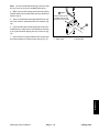
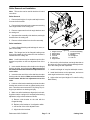
B. Loosen hose clamp (1) and disconnect hydraulic
supply hose (2) from the hydraulic elbow fitting (3).
Plug hose and fitting to prevent leakage and contamination (Fig. 21).
CAUTION
Figure 21
The muffler and muffler tube may be hot.
To avoid possible burns, allow the exhaust system to cool before working on
the muffler and muffler tube.
1. Hose clamp
2. Hydraulic supply hose
3. Hydraulic elbow fitting
4. Hydraulic manifold
D. Remove cap screws (39) and flat washers (11)
from the muffler and exhaust manifold. Remove
muffler and muffler gasket (53) from the engine.
12. Remove exhaust system (Fig. 19).
A. Remove muffler clamp (19) from the muffler (14)
and muffler tube (15).
13. Disconnect throttle cable (Fig. 19).
B. Loosen nut (20) and U–clamp (17). Separate
muffler tube from muffler and slide muffler tube
through U–clamp.
C. Remove cap screws (36) and washers (13) from
the muffler and right rear mount bracket (46).
Reelmaster 2300–D/2600–D
3
4
Page 3 – 15
A. Loosen cap screw (43) enough to separate the
throttle cable from the throttle cable clamp (30).
B. Remove cotter pin (30) from clevis pin (29). Remove clevis pin, throttle tab (31), and throttle cable
from the engine governor lever.
C. Secure throttle cable away from the engine.
Engine
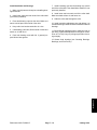
14. Disconnect electrical connections (Fig. 19).
Note: Label all electrical leads for reassembly purposes.
A. Disconnect connector with blue leads from the
alternator.
4
B. Disconnect connector with blue/white leads
from the traction clutch.
1
C. Disconnect connector from the front lift cylinder
microswitch.
3
D. Remove white/black lead from the temperature
sender located on the top of the water pump.
E. Remove tan lead from the high temperature shut
down switch located on the water pump behind the
fan.
2
F. Remove purple lead from the fuel valve solenoid
located above the lift pump.
G. Remove brown lead from the oil pressure switch
located on the front of the cylinder head.
Figure 22
1. Cap screws
2. Whiz nut
3. Radiator rear bracket
4. Frame
H. Remove white lead from the glow plugs located
on the front traction pump side of the cylinder head.
2
I. Remove gray, red, and white leads from the engine starter solenoid located on below the exhaust
manifold.
3
J. Disconnect battery ground from the traction
clutch side of the cylinder head or the fan side of the
cylinder block.
4
K. Remove cap screw (10) and flat washer (11)
from R–clamp (12). Pull wiring harness and hydraulic hoses away from the engine to keep them from
snagging the engine when it is removed. The harness and hoses may be tied to the reservoir support
brackets.
1
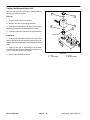
15. Remove radiator assembly.
Figure 23
A. Support the radiator assembly while removing
fasteners.
1. Carriage bolt
2. Whiz nut
3. Radiator bracket
4. Frame
B. Remove cap screws (1) and whiz nuts (2) from
the radiator rear bracket (3) and frame (4) (Fig. 22).
C. Remove carriage bolts (1) and whiz nuts (2) from
the radiator bracket (3) and frame (4) (Fig. 23).
D. Pull radiator assembly out and then up from the
engine to prevent the engine cooling fan from catching the radiator top and bottom shrouds.
Engine
Page 3 – 16
Reelmaster 2300–D/2600–D
16. Remove traction pump drive belt as described in
Traction (Electric) Clutch of the Service and Repairs
section of Chapter 5 – Electrical System.
17. Remove engine (Fig. 19)
A. Attach short section of chain between both lift
tabs (1) located on each end of the cylinder head (2)
(Fig. 24)
1
B. Connect a hoist or chain fall at the center of the
short section of chain. Apply enough tension on the
short chain so that the engine will be supported
when the cap screws (42) securing the engine
mount brackets (22, 34, and 46) are removed.
C. Remove cap screws (42) and flange nuts (27)
from the engine mount brackets (22, 34, and 46)
and the frame.
2
Figure 24
1. Lifting tab
2. Cylinder head
Engine
Note: One person should operate the chain fall or
hoist while another person guides the engine out of the
frame.
Note: Be careful not to damage the engine, fuel lines,
hydraulic hoses, electrical harness or other parts while
removing the engine.
D. Remove engine (25) from the frame.
E. Mount engine onto an engine rebuilding stand.
Reelmaster 2300–D/2600–D
Page 3 – 17
Engine
Engine Reinstallation
E. On the right rear mount bracket (46), tighten cap
screws (36). Torque cap screws from 34 to 42 ft–lb
(4.7 to 5.8 kg–m).
1. Make sure machine is parked on a level surface with
cutting units lowered, and key removed from the start
switch. Chock wheels to keep the machine from moving.
2. Make sure that all parts remove from the engine
during maintenance or rebuilding are reinstalled to the
engine.
5. Reinstall radiator assembly.
A. Place radiator assembly down and then into the
engine to prevent the engine cooling fan from catching the radiator top and bottom shrouds.
3. If mount brackets (22, 34, and 46) were removed reinstall them as follows (Fig. 19):
B. Connect air filter hose extending from the engine
to the air cleaner. Tighten hose clamp.
A. For front mount brackets (34), secure brackets
to the engine (25) with cap screws (36), lock washers (33) and washers (13). Torque cap screws from
34 to 42 ft–lb (4.7 to 5.8 kg–m).
B. For left rear mount bracket (22), secure bracket
to the engine (25) with two cap screws (36), lock
washers (33) and washers (13) through the left
holes. Leave the right holes open for the muffler.
Torque cap screws from 34 to 42 ft–lb (4.7 to 5.8
kg–m).
C. Support the radiator assembly while installing
the fasteners.
D. Install carriage bolts (1) and whiz nuts (2) to the
radiator bracket (3) and frame (4) (Fig. 23).
E. Install cap screws (1) and whiz nuts (2) to the radiator rear bracket (3) and frame (4) (Fig. 22).
6. Reconnect electrical connections (Fig. 19).
C. For right rear mount bracket (46), secure brackets to the engine (25) with cap screws (36), lock
washers (33) and washers (13). Leave cap screws
loose enough so that the position of the bracket
can be adjusted after the engine is installed.
4. Reinstall engine (Fig. 19)
A. Attach short section of chain between both lift
tabs (1) located on each end of the cylinder head (2)
(Fig. 24)
B. Connect a hoist or chain fall at the center of the
short section of chain. Apply enough tension on the
short chain so that the engine will be supported
when the engine is removed from the engine rebuilding stand. Remove engine from the engine rebuilding stand.
A. Untie harness and hoses from the reservoir support brackets. Pull wiring harness and hydraulic
hoses into position; keep them from contacting
moving parts. Install cap screw (10) and flat washer
(11) to R–clamp (12) and tighten to cylinder head.
B. Reconnect connector with blue leads to the alternator.
C. Reconnect connector with blue/white leads to
the traction clutch.
D. Reconnect connector to the front lift cylinder microswitch.
E. Reconnect white/black lead to the temperature
sender located on the top of the water pump.
Note: One person should operate chain fall or hoist
while another person guides the engine into the frame.
F. Reconnect tan lead to the high temperature shut
down switch located on the water pump behind the
fan.
Note: Be careful not to damage the engine, fuel lines,
hydraulic hoses, electrical harness or other parts while
reinstalling the engine.
G. Reconnect purple lead to the fuel valve solenoid
located above the lift pump.
C. Reinstall engine (25) onto the frame. Make sure
fastener holes of the mount brackets (22, 34, and
46) are aligned with the holes on the frame.
D. Secure cap screws (42) and flange nuts (27) to
the mount brackets (22, 34, and 46) and frame.
Engine
Page 3 – 18
H. Reconnect brown lead to the oil pressure switch
located on the front of the cylinder head.
I. Reconnect white lead to the glow plugs located
on the front right side of the cylinder head.
Reelmaster 2300–D/2600–D
J. Reconnect gray, red, and white leads to the engine starter solenoid located on below the exhaust
manifold.
K. Reconnect battery ground to the traction clutch
side of the cylinder head or the left side of the cylinder block.
11. Open fuel shut–off valves under the fuel tank and on
the fuel filter.
12. Fill hydraulic reservoir with hydraulic fluid as described in the General Information section of Chapter 4
– Hydraulic System. Check reservoir for leaks.
13. Add antifreeze to radiator as described in Checking
the Cooling System.
7. Reconnect throttle cable (Fig. 19).
A. Run throttle cable to engine (25).
B. Reinstall clevis pin (29), throttle tab (30), and
throttle cable to the engine governor lever. Reinstall
and lock cotter pin (31) to the clevis pin.
C. Install throttle cable into the throttle cable clamp
(26). Tighten cap screw (43).
14. Slide the left foot rest (5) (Fig. 17) onto the adjusting
rod (2) (Fig. 18). Reinstall cap screws (3) and flange nut
(4) securing the left footrest (5) to the frame. Tighten cap
screws (Fig. 17).
15. Connect adjusting rod to brake arm (3) Install and
lock cotter pin (1) to the adjusting rod (2) (Fig. 18).
16. Reinstall fender bracket (2) and left fender (1) to the
radiator side of the frame (Fig. 17).
A. Position muffler (14) and muffler gasket (45)
onto the exhaust manifold. Install capscrews (39)
and flat washers (11) to the muffler and exhaust
manifold. Tighten cap screws.
A. Secure both cap screws (3) and left fender
bracket (2) to the frame.
B. Reinstall remaining cap screws (3) and flange
nuts (4) securing the fender to the fender bracket
and frame.
B. Reinstall cap screws (36) and washers (13) into
the muffler and right rear mount bracket (46).
C. Slide muffler tube through the U–clamp (17).
Connect muffler tube to the muffler. Tighten nut (20)
and U–clamp.
D. Reinstall muffler clamp (19) to the muffler (14)
and muffler tube (15).
C. Secure cap screw (3) and flange nut (4) to the
left foot rest (5) and the left fender (1).
17. Replace traction pump drive belt as described in
Traction (Electric) Clutch of the Service and Repairs
section of Chapter 5 – Electrical System.
18. Adjust traction pump drive belt as described in the
Adjustment section of Chapter 4 – Hydraulic system.
9. Reconnect hydraulic hoses from the oil cooler.
A. Unplug hydraulic hose (2) and hydraulic elbow
fitting (3). Connect hydraulic supply hose to the hydraulic elbow fitting. Tighten hose clamp (1) (Fig.
21).
B. Unplug hydraulic return hose (2) and hydraulic
fitting (3). Connect hydraulic return hose to the hydraulic fitting. Tighten hose clamp (1) (Fig. 20).
19. Connect negative (–) and then positive (+) battery
cables at the battery.
20. Adjust hand brake as described in the Adjustment
section of Chapter 6 – Wheels and Brakes.
21. Adjust throttle linkage as described in the Adjustment section of this chapter.
22. Bleed fuel system. See Bleeding the Fuel System.
10. Connect hoses to the engine (Fig. 19).
A. Connect fuel hose (return) to the injector nozzle
piping and tighten hose clamp.
23. Check oil level as described in Changing the Engine
OIl and Filter.
B. Unplug fuel hose (44). Connect fuel hose to the
lift pump and tighten hose clamp (38).
24. Replace access covers to the engine.
C. Connect upper radiator hose (18) and lower radiator hose (24) to the engine. Tighten hose clamps
(23).
A. Reinstall left rear panel (radiator side) which
supports the instrument panel.
B. Reinstall right side panel which accesses the
traction pump drive belt.
D. Connect air filter hose to the engine (25).
C. Reinstall hood to the machine and close.
Reelmaster 2300–D/2600–D
Page 3 – 19
Engine
Engine
8. Reinstall exhaust system (Fig. 19).
Engine
Page 3 – 20
Reelmaster 2300–D/2600–D
Chapter 4
Hydraulic System
Table of Contents
Reelmaster 2300–D/2600–D
TESTING . . . . . . . . . . . . . . . . . . . . . . . . . . . . . . . . . . .
Test No. 1: Traction Pump Flow . . . . . . . . . . . . . .
Test No. 2: Charge Pump Flow and
Implement Relief Pressure . . . . . . . . . . . . . . . . .
Test No. 3: Charge Relief Pressure . . . . . . . . . . .
Test No. 4: Real Drive Pump Efficiency . . . . . . .
Test No. 5: Manifold Relief Valve Pressure . . . .
Test No. 6: Cross–over Relief Pressures . . . . . .
Test No. 7: Reel Motor Case Drain . . . . . . . . . . .
ADJUSTMENTS . . . . . . . . . . . . . . . . . . . . . . . . . . . . .
Transmission for Neutral . . . . . . . . . . . . . . . . . . . .
Traction Pedal . . . . . . . . . . . . . . . . . . . . . . . . . . . . .
Traction Pedal Damper . . . . . . . . . . . . . . . . . . . . .
Hydraulic Pump Drive Belt . . . . . . . . . . . . . . . . . .
SERVICE AND REPAIRS . . . . . . . . . . . . . . . . . . . . .
Traction/Charge Pump . . . . . . . . . . . . . . . . . . . . . .
Wheel Motor . . . . . . . . . . . . . . . . . . . . . . . . . . . . . .
2WD/3WD Two Position Valve . . . . . . . . . . . . . . .
Reel Motor Drive Pump . . . . . . . . . . . . . . . . . . . . .
Reel Motor . . . . . . . . . . . . . . . . . . . . . . . . . . . . . . . .
Hydraulic Manifold . . . . . . . . . . . . . . . . . . . . . . . . .
Front Lift Cylinder . . . . . . . . . . . . . . . . . . . . . . . . . .
Rear Lift Cylinder . . . . . . . . . . . . . . . . . . . . . . . . . .
Control and Implement Relief Valves . . . . . . . . .
Hydraulic Reservoir . . . . . . . . . . . . . . . . . . . . . . . .
Flushing the Hydraulic System . . . . . . . . . . . . . . .
Hydraulic System Start–up . . . . . . . . . . . . . . . . . .
Page 4 – 1
19
20
22
24
26
28
30
32
34
34
35
35
36
37
37
44
54
57
60
63
67
71
74
77
79
80
Hydraulic System
Hydraulic
System
SPECIFICATIONS . . . . . . . . . . . . . . . . . . . . . . . . . . . . 2
GENERAL INFORMATION . . . . . . . . . . . . . . . . . . . . . 3
Hydraulic Hoses . . . . . . . . . . . . . . . . . . . . . . . . . . . . 3
Hydraulic Fitting Installation . . . . . . . . . . . . . . . . . . 3
Checking the Hydraulic System Fluid . . . . . . . . . . 5
Changing the Hydraulic System Fluid and Filter . 6
Pushing or Towing the Traction Unit . . . . . . . . . . . 6
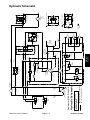
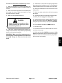
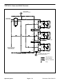
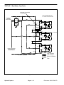
HYDRAULIC SCHEMATIC . . . . . . . . . . . . . . . . . . . . . 7
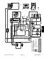
HYDRAULIC FLOW DIAGRAMS . . . . . . . . . . . . . . . . 8
Raise Cutting Units . . . . . . . . . . . . . . . . . . . . . . . . . . 8
Traction Forward . . . . . . . . . . . . . . . . . . . . . . . . . . . 10
Traction Reverse . . . . . . . . . . . . . . . . . . . . . . . . . . . 12
Mow . . . . . . . . . . . . . . . . . . . . . . . . . . . . . . . . . . . . . . 14
SPECIAL TOOLS . . . . . . . . . . . . . . . . . . . . . . . . . . . . 16
Hydraulic Pressure Test Kit . . . . . . . . . . . . . . . . . . 16
Hydraulic Tester – Pressure and Flow . . . . . . . . 16
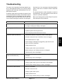
TROUBLESHOOTING . . . . . . . . . . . . . . . . . . . . . . . . 17
Hydraulic Oil Leaks . . . . . . . . . . . . . . . . . . . . . . . . . 17
Foaming Hydraulic Fluid . . . . . . . . . . . . . . . . . . . . 17
Hydraulic System Operates Hot . . . . . . . . . . . . . . 17
Neutral Is Difficult to Find or Operates in One
Direction Only . . . . . . . . . . . . . . . . . . . . . . . . . . . . 17
Traction Response Is Sluggish . . . . . . . . . . . . . . . 17
No Traction in Either Direction . . . . . . . . . . . . . . . 17
Wheel Motor Will Not Turn . . . . . . . . . . . . . . . . . . 18
Wheel Motor Will Not Hold Load In Neutral . . . . 18
Noisy Wheel Motor Drive Pump (Cavitation) . . . 18
Reels Will Not Turn . . . . . . . . . . . . . . . . . . . . . . . . . 18
Reel Speed Is Erratic . . . . . . . . . . . . . . . . . . . . . . . 18
Reel Motor Case Drain Flow Is Excessive . . . . . 18
Cutting Units Will Not Lift or Lift Slowly . . . . . . . . 18
Cutting Units Raise, but Will Not Stay Up . . . . . . 18
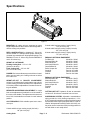
Specifications
Item
Description
Traction Pump
Maximum Operating Pressure
Maximum Intermittent Pressure
Maximum Rated Speed
Rated Flow @ Maximum Rated Speed and Pressure
Variable displacement piston pump
3000 PSI (207 bar)
5000 PSI (345 bar)
3600 RPM
17 GPM (64 LPM)
Charge Pump
Maximum Operating Pressure
Maximum Rated Speed
Rated Flow @ Maximum Rated Speed and Pressure
Charge Pressure
Gerotor pump
500 PSI (34.5 bar)
3600 RPM
3.5 GPM (13.2 LPM)
100 to 150 PSI (6.9 to 10.0 bar)
Implement (Lift) Relief Valve
Implement Relief Pressure
Differential area relief valve
450 – 525 PSI (31.1 to 36.2 bar)
Wheel Motors
Maximum Operating Pressure
Maximum Intermittent Pressure
Maximum Rated Speed
Rated Flow @ Maximum Rated Speed and Pressure
Orbital rotor pump (with shuttle valve on left front motor)
2000 PSI (138 bar)
3000 PSI (207 bar)
267 RPM
15 GPM (57 LPM)
Reel Motor Drive Pump
Maximum Operating Pressure
Maximum Intermittent Pressure
Maximum Rated Speed
Rated Flow @ Maximum Rated Speed and Pressure
Positive displacement gear type pump
4000 PSI (276 bar)
4400 PSI (304 bar)
4000 RPM
8.5 GPM (32 LPM)
Hydraulic Manifold Relief Valve
Cutting Circuit Relief Pressure
Differential area relief valve
2700 to 3300 PSI (186.3 to 227.7 bar)
Reel Motor
Cross–over Relief Pressure
Maximum Operating Pressure
Maximum Intermittent Pressure
Maximum Rated Speed
Rated Flow @ Maximum Rated Speed and Pressure
Gear motor
1350 to 1650 PSI (93.2 to 113.9 bar)
2250 PSI (155 bar)
3000 PSI (207 bar)
3000 RPM
28.6 GPM (108 LPM)
Lift Control Valve
Spool type directional control valve
Hydraulic Filter
10 Micron spin–on cartridge type
Hydraulic Oil
* Mobil 424/Shell Donax TD or equivalent
Hydraulic Reservoir
Hydraulic System
Reservoir capacity 2.3 gal. U.S. (8.7 L)
Total system capacity approximately 3.3 gal. U.S. (12.5 L)
Page 4 – 2
Reelmaster 2300–D/2600–D
General Information
Hydraulic Hoses
Hydraulic hoses are subject to extreme conditions such
as pressure differentials during operation and exposure
to weather, sun, chemicals, very warm storage conditions, or mishandling during operation or maintenance.
These conditions can cause damage or premature deterioration. Some hoses are more susceptible to these
conditions than others. Inspect the hoses frequently for
signs of deterioration or damage.
Before disconnecting or performing any
work on hydraulic system, all pressure in
system must be relieved by stopping the
engine and lowering or supporting the
box and/or other attachment.
Keep body and hands away from pin hole
leaks or nozzles that eject hydraulic fluid
under high pressure. Use paper or cardboard, not hands, to search for leaks.
Hydraulic fluid escaping under pressure
can have sufficient force to penetrate the
skin and cause serious injury. If fluid is
injected into the skin, it must be surgically removed within a few hours by a doctor
familiar with this type of injury. Gangrene
may result from such an injury.
Hydraulic
System
When replacing a hydraulic hose, be sure that the hose
is straight (not twisted) before tightening the fittings.
This can be done by observing the imprint on the hose.
Use two wrenches; hold the hose straight with one and
tighten the hose swivel nut onto the fitting with the other.
WARNING
Hydraulic Fitting Installation
O–Ring Face Seal
Nut
1. Make sure both threads and sealing surfaces are
free of burrs, nicks, scratches, or any foreign material.
Body
Sleeve
2. Make sure the O–ring is installed and properly
seated in the groove. It is recommended that the O–ring
be replaced any time the connection is opened.
Seal
3. Lubricate the O–ring with a light coating of oil.
4. Put the tube and nut squarely into position on the
face seal end of the fitting and tighten the nut until finger
tight.
Figure 1
5. Mark the nut and fitting body. Hold the body with a
wrench. Use another wrench to tighten the nut to the correct flats from finger tight (F.F.F.T.). The markings on the
nut and fitting body will verify that the connection has
been tightened.
Size
4 (1/4 in. nominal hose or tubing)
6 (3/8 in.)
8 (1/2 in.)
10 (5/8 in.)
12 (3/4 in.)
16 (1 in.)
Reelmaster 2300–D/2600–D
Final
Position
Mark Nut
and Body
F.F.F.T.
Extend Line
.75 + .25
.75 + .25
.75 + .25
1.00 + .25
.75 + .25
.75 + .25
Finger Tight
Initial
Position
After Proper Tightening
Figure 2
Page 4 – 3
Hydraulic System
SAE Straight Thread O–Ring Port – Non–adjustable
1. Make sure both threads and sealing surfaces are
free of burrs, nicks, scratches, or any foreign material.
2. Always replace the O–ring seal when this type of fitting shows signs of leakage.
O–Ring
3. Lubricate the O–ring with a light coating of oil.
4. Install the fitting into the port and tighten it down full
length until finger tight.
Figure 3
5. Tighten the fitting to the correct flats from finger tight
(F.F.F.T.).
Size
4 (1/4 in. nominal hose or tubing)
6 (3/8 in.)
8 (1/2 in.)
10 (5/8 in.)
12 (3/4 in.)
16 (1 in.)
F.F.F.T.
1.00 + .25
1.50 + .25
1.50 + .25
1.50 + .25
1.50 + .25
1.50 + .25
SAE Straight Thread O–Ring Port – Adjustable
1. Make sure both threads and sealing surfaces are
free of burrs, nicks, scratches, or any foreign material.
2. Always replace the O–ring seal when this type of fitting shows signs of leakage.
Lock Nut
3. Lubricate the O–ring with a light coating of oil.
4. Turn back the jam nut as far as possible. Make sure
the back up washer is not loose and is pushed up as far
as possible (Step 1).
Back–up Washer
O–Ring
5. Install the fitting into the port and tighten finger tight
until the washer contacts the face of the port (Step 2).
6. To put the fitting in the desired position, unscrew it
by the required amount, but no more than one full turn
(Step 3).
Figure 4
Step 1
Step 3
Step 2
Step 4
7. Hold the fitting in the desired position with a wrench
and turn the jam nut with another wrench to the correct
flats from finger tight (F.F.F.T.) (Step 4).
Size
4 (1/4 in. nominal hose or tubing)
6 (3/8 in.)
8 (1/2 in.)
10 (5/8 in.)
12 (3/4 in.)
16 (1 in.)
Hydraulic System
F.F.F.T.
1.00 + .25
1.50 + 25
1.50 + .25
1.50 + .25
1.50 + .25
1.50 + .25
Figure 5
Page 4 – 4
Reelmaster 2300–D/2600–D
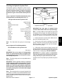
Checking the Hydraulic System Fluid
The hydraulic system is designed to operate on anti–
wear hydraulic fluid. The machine’s reservoir is filled at
the factory with approximately 3.3 gallons (12.5 liters) of
Mobil 424 hydraulic fluid. Check level of hydraulic
fluid before engine is first started and daily thereafter.
1
Group 1 Hydraulic Fluid (Recommended for ambient temperatures consistently below 100 F.):
2
ISO type 46/68 anti–wear hydraulic fluid
Note:
able.
Mobil Fluid 424
Amoco 1000
Hy–Tran
TDH
Donax TD
Hydraulic/Tractor Fluid
Tractor Hydraulic Fluid
BP HYD TF
Eldoran UTH
Torque Fluid
Power–Tran 3
Hyken 052
HG Fluid
The fluids within this group are interchange-
Group 2 Hydraulic Fluid (Biodegradable):
ISO VG 32/46 anti–wear hydraulic fluid
Mobil
EAL 224 H
Figure 6
1. Hydraulic reservoir cap
2. Sight gauge
IMPORTANT: Use only types of hydraulic fluids
specified. Other fluids could cause system damage.
Note: A red dye additive for the hydraulic system fluid
is available in 2/3 oz bottles. One bottle is sufficient for
4 to 6 gallons (15 to 22 liters) of hydraulic fluid. Order
Part No. 44–2500 from your Authorized Toro Distributor.
1. Position machine on a level surface. Make sure engine is off and parking brake is set.
2. Check level of the fluid by viewing into the sight
gauge. If the fluid is cold, the level should be at the bottom of the gauge. If the fluid is hot, the level should be
at the center of the gauge.
3. If fluid level is not at center of gauge, remove cap
from the hydraulic fluid reservoir and slowly fill reservoir
with Mobil 424 or equivalent hydraulic fluid until level
reaches center of sight gauge. DO NOT OVERFILL
IMPORTANT: Due to the nature of biodegradable
fluids, it is critical that the fluid be changed at the
recommended intervals or severe hydraulic component damage may occur.
IMPORTANT: To prevent system contamination,
clean top of hydraulic fluid containers before puncturing. Assure pour spout and funnel are clean.
Note: The fluid in this group is not compatible with the
fluids in group 1.
4.Install reservoir cap. Wipe up any fluid that may have
spilled.
IMPORTANT: These hydraulic fluids are specified
to allow optimal operation of the machine in a wide
range of temperatures encountered. The group 1
fluids are a multi–viscosity hydraulic fluids which
allows operation at lower temperatures without the
increased viscosity that is associated with straight
viscosity fluids.
Note: When changing from one type of hydraulic fluid
to the other, be certain to remove all the old fluid from the
system, because some brands of one type are not completely compatible with some brands of the other type of
hydraulic fluid.
Reelmaster 2300–D/2600–D
Page 4 – 5
Hydraulic System
Hydraulic
System
Mobil
Amoco
International Harvester
Texaco
Shell
Union OIl
Chevron
BP Oil
Boron OIl
Exxon
Conoco
Kendall
Phillips
Changing the Hydraulic System Fluid and Filter
The hydraulic system filter must be changed initially, after the first five hours of operation, and thereafter every
200 hours of operation or yearly, whichever comes first.
Use a genuine Toro oil filter for replacement. The hydraulic fluid must be changed every 400 hours of operation or yearly, whichever comes first.
1
1. Park the machine on a level surface, lower the cutting units, set parking brake and turn the engine off.
2. If only the filter is to be changed, remove reservoir
cap and insert reservoir plug (Fig. 7), to block outlet. This
will retain most of the fluid in reservoir when filter is removed.
2
Figure 7
3. Clean the area around the hydraulic oil filter. Remove filter from the bottom of the filter housing and allow
the oil to flow into a drain pan. Use a bottom type filter
wrench. Dispose of the oil filter properly.
1. Reservoir plug
2. Reservoir outlet
4. Apply a film of oil on the filter gasket. Install filter by
hand until gasket contacts the mounting head; then
tighten filter an additional three–fourths turn.
5. Fill the reservoir to proper level, refer to Checking
the Hydraulic System Fluid.
6. Place all controls in neutral or disengaged position
and start engine. Run engine at lowest possible RPM to
purge the system of air.
1
Figure 8
7. Run engine until lift cylinders extend and retract and
forward and reverse wheel motion is achieved.
1. Hydraulic oil filter
8. Stop the engine and check the oil level in reservoir,
add oil if necessary.
9. Check all connections for leaks.
Pushing or Towing the Traction Unit
In case of emergency, the Reelmaster 2300–D can be
towed for a short distance. However, Toro does not recommend this as a standard procedure.
IMPORTANT: Do not tow the machine faster than
2–3 mph because drive system may be damaged. If
machine must be moved a considerable distance,
transport it on a truck or trailer.
1. Locate by–pass valve on pump and rotate it 90_
so the by–pass valve is horizontal.
2. Before the starting engine, close by–pass valve by
rotating it 90_ so the by–pass valve is vertical. Do not
start engine when valve is open.
1
Figure 9
1. By–pass valve
Hydraulic System
Page 4 – 6
Reelmaster 2300–D/2600–D
Reelmaster 2300–D/2600–D
Page 4 – 7
WHEEL MOTOR
LEFT
REVERSE
(FRONT
LINE)
OUTER
12 in3
[197cc]
FORWARD
(REAR
LINE)
REAR WHEELDRIVE CIRCUIT IS
NOT USED ON 2WD UNITS
Solenoid S1 is shown
de–energized
Hydraulic Schematic
Reelmaster 2300–D/2600–D
LIFT CYL
REAR
INNER
LIFT CYL
FRONT
B–UPPER
A–LOWER
12 in3
[197cc]
T2
WHEEL MOTOR
RIGHT
P1
REEL
RELIEF
3000 psi
R1
.49 in3
GEAR PUMP
[8.0cc]
REEL
ON–OFF
VALVE
TOP
REEL LIFT
CONTROL VALVE
Hydraulic System
Hydraulic
System
MD1
BACKLAPPING
VALVE
FRONT
G1
FILTER
10 MICRON NOM
LOW PRESSURE
B
BOTTOM
TOP
FRONT
BOTTOM
VALVE TOP A
FLOW CONTROL VALVE
LC1
LOGIC
VALVE
FCI
REEL SPEED CONTROLLER
S1
CHARGE PUMP
.42 IN3
[6.9CC]
CHARGE RELIEF
100–150 psi
TOW VALVE
TRACTION PUMP
1.24 in3
[20.3 cc)
BOTTOM
PC FLOW CONTROL
2.1 GPM
REVERSE
FORWARD
1
M4
M6
D3
M5
M1
D1
M2
M3
D2
LIFT RELIEF
475 psi
COOLER
RESERVOIR
2.3 GALLON
[8.7 LITER]
OUT (REAR)
IN (FRONT)
LH
CTR
RH
2
BOTTOM
12 in3
[197cc]
WHEEL MOTOR
REAR
REEL MOTORS
1.54 in3
[25.2cc]
CROSS–OVER RELIEF
1500 PSI
REEL MOTOR SCHEMATIC
LEFT WHEEL MOTOR SCHEMATIC
TOP
2WD/3WD SELECTOR
(SHOWN IN 3WD)
Hydraulic Schematic
Hydraulic Flow Diagrams
Raise Cutting Units
The charge pump is part of the traction pump and is directly coupled to it. It supplies hydraulic pressure for
raising and lowering cutting units and maintaining 100
to 150 PSI to the low pressure side of the traction circuit
(piston pump). The pump takes its suction through a filter from the reservoir.
During conditions of not lifting or lowering cutting units,
flow from the charge pump goes to the control valve and
is by–passed (control valve position not shown) directly
to the suction of the piston pump and the charge relief
valve.
When the cutting units are to be raised, the control valve
spool is positioned down and flow is directed out the top
of the control valve to the lower and outer portions of the
Hydraulic System
lift cylinders. Hydraulic pressure against the cylinder
pistons pushes the shafts out. At the same time, the pistons push the hydraulic fluid in the upper and inner portions of the lift cylinders out and through the control valve
to the piston pump suction. When the control valve lever
is released, spring action returns the spool to the center
position and by–passes flow back to the piston pump
suction. Lift cylinder movement is stopped. The cylinder
position is locked in place since there is no complete circuit of flow to and from the lift cylinders.
Circuit operation for lowering the lift cylinders is similar
to raising them. However, the control valve spool is
shifted up and flow is reversed to and from the lift cylinders, thus moving the cutting units down.
Page 4 – 8
Reelmaster 2300–D/2600–D
Reelmaster 2300–D/2600–D
Page 4 – 9
Hydraulic System
REVERSE
(FRONT
LINE)
OUTER
FORWARD
(REAR
LINE)
12 in3
[197cc]
WHEEL MOTOR
LEFT
T2
MD1
BACKLAPPING
VALVE
FRONT
G1
Solenoid S1 is shown de–energized
Control valve is positioned up
REEL
RELIEF
3000 psi
FLOW CONTROL VALVE
Hydraulic
System
REEL
ON–OFF
VALVE
1
M5
M1
D1
M2
D3
M3
D2
LIFT RELIEF
475 psi
COOLER
RESERVOIR
2.3 GALLON
[8.7 LITER]
OUT (REAR)
IN (FRONT)
M4
S1
LC1
LOGIC
VALVE
FCI
REEL SPEED CONTROLLER
FILTER
10 MICRON NOM
LOW PRESSURE
BOTTOM
TOP
FRONT
B
M6
R1
.49 in3
GEAR PUMP
[8.0cc]
CHARGE RELIEF
100–150 psi
TOP
BOTTOM
VALVE TOP A
REEL LIFT
CONTROL VALVE
Flow
P1
CHARGE PUMP
.42 IN3
[6.9CC]
TOW VALVE
TRACTION PUMP
1.24 in3
(20.3 cc)
BOTTOM
PC FLOW CONTROL
2.1 GPM
REVERSE
High Pressure
Low Pressure (Charge)
Return or Suction
Raise Cutting Units
Reelmaster 2300–D/2600–D
LIFT CYL
REAR
INNER
LIFT CYL
FRONT
B–UPPER
A–LOWER
12 in3
[197cc]
WHEEL MOTOR
RIGHT
FORWARD
LH
CTR
RH
2
BOTTOM
REEL MOTORS
1.54 in3
[25.2cc]
CROSS–OVER RELIEF
1500 PSI
REEL MOTOR SCHEMATIC
LEFT WHEEL MOTOR SCHEMATIC
12 in3
[197cc]
WHEEL MOTOR
REAR
TOP
2WD/3WD SELECTOR
(SHOWN IN 3WD)
Traction Forward
The traction pump is driven by the engine through the
pulley, pump drive belt, and electric clutch. The traction
circuit of the hydraulic system acts essentially as a
closed loop. Taking its suction directly from the return
side of the wheel motors of the traction circuit, the traction pump supplies oil flow to the wheel motors through
the supply side of the traction circuit.
With the engine running, clutch engaged, and traction
pedal in the neutral position, the traction pump supplies
no flow to the wheel motors. When the traction pedal is
pressed to the forward position, the linkage from the
pedal positions the swash plate in the traction motor so
oil flows out the top port of the pump. Oil flow out of the
top port goes to the wheel motors and turns them in the
forward direction. The 2WD/3WD selector valve allows
flow to the rear wheel in the 3WD position and by–
passes the rear wheel in the 2WD position.
Oil flowing out of the wheel motors returns to the bottom
port of the traction pump and is continuously pumped
out the top port. However, oil flow out of the rear wheel
motor must pass through the check valve portion of the
PC flow controller before returning to the traction pump.
Hydraulic System
A small amount of hydraulic oil leaves the traction circuit
through the bi–directional shuttle valve in the front left
wheel motor. This oil is cooled as it flows through the
cooler and returned to the reservoir.
Filtered hydraulic oil is supplied to the traction circuit
from the charge pump though the lift control valve and
back through the charge circuit check valves. This filtered oil replaces oil losses from flow through the shuttle
valve and small amounts of leakage. The charge pump
and shuttle valve circuits allow for indirect cooling and
filtering of the traction circuit.
In the forward direction, the PC flow controller has a special function. When a unit is moving downhill, the operator will return the traction pedal to the neutral position.
In this situation, the front wheel motors act as hydraulic
pumps and reverse the oil flow through the traction circuit. The PC flow controller will restrict flow to the rear
motor sufficiently, so the reverse flow is by–passed
through the 2WD/3WD selector (check) valve around
the rear wheel motor. This action will prevent a loss of
steering control should the rear motor turn in the reverse
direction. As a result, there is no 3WD in reverse
Page 4 – 10
Reelmaster 2300–D/2600–D
Reelmaster 2300–D/2600–D
Page 4 – 11
Hydraulic System
REVERSE
(FRONT
LINE)
OUTER
FORWARD
(REAR
LINE)
Solenoid S1 is shown
de–energized
High Pressure
Low Pressure (Charge)
Return or Suction
Flow
Traction Forward
12 in3
[197cc]
MOTOR
Reelmaster 2300–D/2600–D WHEELLEFT
LIFT CYL
REAR
INNER
LIFT CYL
FRONT
B–UPPER
A–LOWER
12 in3
[197cc]
WHEEL MOTOR
RIGHT
T2
P1
CHARGE PUMP
.42 IN3
[6.9CC]
REEL
RELIEF
3000 psi
R1
.49 in3
GEAR PUMP
[8.0cc]
CHARGE RELIEF
100–150 psi
TOP
B
REEL LIFT
CONTROL VALVE
MD1
BACKLAPPING
VALVE
FRONT
G1
FILTER
10 MICRON NOM
LOW PRESSURE
BOTTOM
TOP
FRONT
BOTTOM
VALVE TOP A
FLOW CONTROL VALVE
Hydraulic
System
REEL
ON–OFF
VALVE
S1
LC1
LOGIC
VALVE
FCI
REEL SPEED CONTROLLER
TOW VALVE
TRACTION PUMP
1.24 in3
[20.3 cc)
BOTTOM
PC FLOW CONTROL
2.1 GPM
REVERSE
FORWARD
1
M4
M6
D3
M5
M1
D1
M2
M3
D2
LIFT RELIEF
475 psi
COOLER
RESERVOIR
2.3 GALLON
[8.7 LITER]
OUT (REAR)
IN (FRONT)
LH
CTR
RH
2
BOTTOM
12 in3
[197cc]
WHEEL MOTOR
REAR
REEL MOTORS
1.54 in3
[25.2cc]
CROSS–OVER RELIEF
1500 PSI
REEL MOTOR SCHEMATIC
LEFT WHEEL MOTOR SCHEMATIC
TOP
2WD/3WD SELECTOR
(SHOWN IN 3WD)
Traction Reverse
The traction circuit operates essentially the same in reverse as it does in the forward direction. However, the
flow through the circuit is reversed and by–passes the
rear wheel motor.
With the engine running, clutch engaged, and traction
pedal in the neutral position, the traction pump supplies
no flow to the wheel motors. When the traction pedal is
pressed to the reverse position, the linkage from the
pedal positions the swash plate in the traction motor so
oil flows out the bottom port of the pump. Oil flow out of
the bottom port goes to the wheel motors and turns them
in the reverse direction. The 2WD/3WD selector valve
by–passes the rear wheel in both the 2WD and 3WD
positions.
Oil flowing out of the wheel motors returns to the top port
of the traction pump and is continuously pumped out the
Hydraulic System
bottom port. However, oil flow to the rear wheel motor is
blocked by the check valve portion of the PC flow controller and forced through the restriction before going to
the motor. Flow is limited to 2.1 GPM to the rear wheel
motor. This flow is sufficient to prevent cavitation on the
rear motor in reverse.
Because of the by–passing of the rear wheel motor in reverse and the resistance to flow of the two front wheel
motors, all the traction flow is by–passed directly back
to the traction pump when the traction pedal is initially
pushed in the reverse direction. This direct by–passing
of the traction circuit causes a delay in the response of
the traction pedal in reverse until traction flow exceeds
2.1 GPM (7.9 LPM) through the PC flow controller.
The charge and shuttle valve circuits function the same
in reverse as they did in the forward direction.
Page 4 – 12
Reelmaster 2300–D/2600–D
Reelmaster 2300–D/2600–D
Page 4 – 13
Hydraulic System
REVERSE
(FRONT
LINE)
OUTER
FORWARD
(REAR
LINE)
Solenoid S1 is shown
de–energized
High Pressure
Low (Charge) Pressure
Return or Suction
Flow
Traction Reverse
12 in3
[197cc]
MOTOR
Reelmaster 2300–D/2600–D WHEELLEFT
LIFT CYL
REAR
INNER
LIFT CYL
FRONT
B–UPPER
A–LOWER
12 in3
[197cc]
WHEEL MOTOR
RIGHT
T2
P1
CHARGE PUMP
.42 IN3
[6.9CC]
REEL
RELIEF
3000 psi
R1
.49 in3
GEAR PUMP
[8.0cc]
CHARGE RELIEF
100–150 psi
B
REEL LIFT
CONTROL VALVE
MD1
BACKLAPPING
VALVE
FRONT
G1
FILTER
10 MICRON NOM
LOW PRESSURE
BOTTOM
TOP
FRONT
TOP
BOTTOM
VALVE TOP A
FLOW CONTROL VALVE
Hydraulic
System
REEL
ON–OFF
VALVE
S1
LC1
LOGIC
VALVE
FCI
REEL SPEED CONTROLLER
TOW VALVE
TRACTION PUMP
1.24 in3
[20.3 cc)
BOTTOM
PC FLOW CONTROL
2.1 GPM
REVERSE
FORWARD
1
M4
M6
D3
M5
M1
D1
M2
M3
D2
LIFT RELIEF
425 psi
COOLER
RESERVOIR
2.3 GALLON
[8.7 LITER]
OUT (REAR)
IN (FRONT)
LH
CTR
RH
2
BOTTOM
REEL MOTORS
1.54 in3
[25.2cc]
CROSS–OVER RELIEF
1500 PSI
REEL MOTOR SCHEMATIC
LEFT WHEEL MOTOR SCHEMATIC
12 in3
[197cc]
WHEEL MOTOR
REAR
TOP
2WD/3WD SELECTOR
(SHOWN IN 3WD)
Mow
The reel motor drive pump is directly coupled to the the
traction pump which is driven directly by the engine
through the electric clutch. Taking its suction directly
from the reservoir, the reel motor drive pump supplies oil
flow to the hydraulic manifold block and to the reel motors.
With the engine running, the clutch engaged, and the
cutting unit switch pushed in to the OFF position, oil
flows into inlet port (P1) and through deenergized solenoid valve (S1) bypassing the reel motors. Oil then flows
directly back to the reservoir through the oil cooler.
When the cutting unit switch is pulled out to the ON position with the engine running and the clutch engaged, solenoid valve (S1) is energized and shut, hydraulic
system pressure builds up, and flow is diverted to the
reel motors. Oil flow from port (P1) flows through the 11
position reel speed control valve. Flow across the speed
control valve is pressure compensated by the logic car-
Hydraulic System
tridge valve (LC1). The logic cartridge valve maintains
a pressure differential of 75 PSI (5.2 bar) across the
speed control valve. Any excess flow above what the
speed control valve is set for is bypassed to the reservoir
through the logic cartridge valve. With the backlap valve
(MD1) in the mow position, oil flows through the valve
and reel motors which are connected in series. Oil flows
through the right, center, and then left reel motor as it
turns the motors in the mow direction. The oil then returns to the reservoir.
Relief valve (R1) limits system pressure and is set at
3000 PSI (207 bar). When the valve opens, oil is diverted back to the reservoir.
Backlapping operation is the same as mowing operation, except for the position of the backlap valve (MD1).
The backlap valve is in the backlap position allowing oil
flow through the left, center, and then right reel motor as
it turns the motors in the backlap direction.
Page 4 – 14
Reelmaster 2300–D/2600–D
Reelmaster 2300–D/2600–D
Page 4 – 15
Hydraulic System
REVERSE
(FRONT
LINE)
OUTER
FORWARD
(REAR
LINE)
Flow
High Pressure
Low Pressure (Charge)
Return or Suction
Solenoid S1 is shown energized
Valve MD1 is selected to mow
Mow
12 in3
[197cc]
MOTOR
Reelmaster 2300–D/2600–D WHEELLEFT
LIFT CYL
REAR
INNER
LIFT CYL
FRONT
B–UPPER
A–LOWER
12 in3
[197cc]
WHEEL MOTOR
RIGHT
T2
P1
REEL
RELIEF
3000 psi
R1
.49 in3
GEAR PUMP
[8.0cc]
S1
CHARGE PUMP
.42 IN3
[6.9CC]
CHARGE RELIEF
100–150 psi
Hydraulic
System
B
REEL LIFT
CONTROL VALVE
MD1
BACKLAPPING
VALVE
FRONT
G1
FILTER
10 MICRON NOM
LOW PRESSURE
BOTTOM
TOP
FRONT
TOP
BOTTOM
VALVE TOP A
FLOW CONTROL VALVE
REEL
ON–OFF
VALVE
LC1
LOGIC
VALVE
FCI
REEL SPEED CONTROLLER
TOW VALVE
TRACTION PUMP
1.24 in3
[20.3 cc)
BOTTOM
PC FLOW CONTROL
2.1 GPM
REVERSE
FORWARD
1
M4
M6
D3
M5
M1
D1
M2
M3
D2
LIFT RELIEF
425 psi
COOLER
RESERVOIR
2.3 GALLON
[8.7 LITER]
OUT (REAR)
IN (FRONT)
LH
CTR
RH
2
BOTTOM
REEL MOTORS
1.54 in3
[25.2cc]
CROSS–OVER RELIEF
1500 PSI
REEL MOTOR SCHEMATIC
LEFT WHEEL MOTOR SCHEMATIC
12 in3
[197cc]
WHEEL MOTOR
REAR
TOP
2WD/3WD SELECTOR
(SHOWN IN 3WD)
Special Tools
Order these tools from the TORO SPECIAL TOOLS
AND APPLICATIONS GUIDE (COMMERCIAL PRODUCTS).
Some tools may also be available from a local supplier.
Hydraulic Pressure Test Kit
Use to take various pressure readings for diagnostic
tests. Quick disconnect fittings provided attach directly
to mating fittings on machine test ports without tools. A
high pressure hose is provided for remote readings.
Contains one each, 1000, 5000 and 10000 PSI gauges.
Use gauges as recommended in Testing section of this
chapter.
Figure 10
Hydraulic Tester – Pressure and Flow
Figure 11
A protector valve cuts out when pressure is about to
exceed the normal range for the gauge. The cutout
pressure is adjustable.
This tester requires o–ring face seal (ORFS) adapter fittings for use on this machine.
1. INLET HOSE: Hose connected from the system circuit to the inlet side of the hydraulic tester.
2. LOAD VALVE: A simulated working load is created
in the circuit by turning the valve to restrict flow.
3. LOW PRESSURE GAUGE: Low range gauge to
provide accurate reading at low pressure, 0 to 1000 PSI.
4. HIGH PRESSURE GAUGE: High range gauge
which accommodates pressures beyond the capacity of
the low pressure gauge, 0 to 5,000 PSI.
5. FLOW METER: This meter measures actual oil flow
in the operating circuit with a gauge rated at 15 GPM.
6. OUTLET HOSE: A hose from the outlet side of the
hydraulic tester connects to the hydraulic system circuit.
Hydraulic System
Page 4 – 16
Reelmaster 2300–D/2600–D
Troubleshooting
The cause of an improperly functioning hydraulic system is best diagnosed with the use of proper testing
equipment and a thorough understanding of the complete hydraulic system.
A hydraulic system with an excessive increase in heat
or noise has a potential for failure. Should either of these
conditions be noticed, immediately stop the machine,
turn off the engine, locate the cause of the trouble, and
correct it before allowing the machine to be used again.
Continued use of an improperly functioning hydraulic
system could lead to extensive internal component
damage.
The charts that follow contain information to assist in
troubleshooting. There may possibly be more than one
cause for a machine malfunction.
Refer to the Testing section of this Chapter for precautions and specific test procedures.
ÁÁÁÁÁÁÁÁÁÁÁÁÁ
ÁÁÁÁÁÁÁÁÁÁÁÁÁÁÁÁÁÁÁÁÁÁ
ÁÁÁÁÁÁÁÁÁÁÁÁÁ
ÁÁÁÁÁÁÁÁÁÁÁÁÁÁÁÁÁÁÁÁÁÁ
ÁÁÁÁÁÁÁÁÁÁÁÁÁ
ÁÁÁÁÁÁÁÁÁÁÁÁÁÁÁÁÁÁÁÁÁÁ
ÁÁÁÁÁÁÁÁÁÁÁÁÁ
ÁÁÁÁÁÁÁÁÁÁÁÁÁÁÁÁÁÁÁÁÁÁ
ÁÁÁÁÁÁÁÁÁÁÁÁÁ
ÁÁÁÁÁÁÁÁÁÁÁÁÁÁÁÁÁÁÁÁÁÁ
ÁÁÁÁÁÁÁÁÁÁÁÁÁ
ÁÁÁÁÁÁÁÁÁÁÁÁÁÁÁÁÁÁÁÁÁÁ
ÁÁÁÁÁÁÁÁÁÁÁÁÁ
ÁÁÁÁÁÁÁÁÁÁÁÁÁÁÁÁÁÁÁÁÁÁ
ÁÁÁÁÁÁÁÁÁÁÁÁÁ
ÁÁÁÁÁÁÁÁÁÁÁÁÁÁÁÁÁÁÁÁÁÁ
ÁÁÁÁÁÁÁÁÁÁÁÁÁ
ÁÁÁÁÁÁÁÁÁÁÁÁÁÁÁÁÁÁÁÁÁÁ
ÁÁÁÁÁÁÁÁÁÁÁÁÁ
ÁÁÁÁÁÁÁÁÁÁÁÁÁÁÁÁÁÁÁÁÁÁ
ÁÁÁÁÁÁÁÁÁÁÁÁÁ
ÁÁÁÁÁÁÁÁÁÁÁÁÁÁÁÁÁÁÁÁÁÁ
ÁÁÁÁÁÁÁÁÁÁÁÁÁ
ÁÁÁÁÁÁÁÁÁÁÁÁÁÁÁÁÁÁÁÁÁÁ
ÁÁÁÁÁÁÁÁÁÁÁÁÁ
ÁÁÁÁÁÁÁÁÁÁÁÁÁÁÁÁÁÁÁÁÁÁ
ÁÁÁÁÁÁÁÁÁÁÁÁÁ
ÁÁÁÁÁÁÁÁÁÁÁÁÁÁÁÁÁÁÁÁÁÁ
ÁÁÁÁÁÁÁÁÁÁÁÁÁ
ÁÁÁÁÁÁÁÁÁÁÁÁÁÁÁÁÁÁÁÁÁÁ
ÁÁÁÁÁÁÁÁÁÁÁÁÁ
ÁÁÁÁÁÁÁÁÁÁÁÁÁÁÁÁÁÁÁÁÁÁ
ÁÁÁÁÁÁÁÁÁÁÁÁÁ
ÁÁÁÁÁÁÁÁÁÁÁÁÁÁÁÁÁÁÁÁÁÁ
ÁÁÁÁÁÁÁÁÁÁÁÁÁ
ÁÁÁÁÁÁÁÁÁÁÁÁÁÁÁÁÁÁÁÁÁÁ
ÁÁÁÁÁÁÁÁÁÁÁÁÁ
ÁÁÁÁÁÁÁÁÁÁÁÁÁÁÁÁÁÁÁÁÁÁ
ÁÁÁÁÁÁÁÁÁÁÁÁÁ
ÁÁÁÁÁÁÁÁÁÁÁÁÁÁÁÁÁÁÁÁÁÁ
ÁÁÁÁÁÁÁÁÁÁÁÁÁ
ÁÁÁÁÁÁÁÁÁÁÁÁÁÁÁÁÁÁÁÁÁÁ
ÁÁÁÁÁÁÁÁÁÁÁÁÁ
ÁÁÁÁÁÁÁÁÁÁÁÁÁÁÁÁÁÁÁÁÁÁ
ÁÁÁÁÁÁÁÁÁÁÁÁÁ
ÁÁÁÁÁÁÁÁÁÁÁÁÁÁÁÁÁÁÁÁÁÁ
ÁÁÁÁÁÁÁÁÁÁÁÁÁ
ÁÁÁÁÁÁÁÁÁÁÁÁÁÁÁÁÁÁÁÁÁÁ
ÁÁÁÁÁÁÁÁÁÁÁÁÁ
ÁÁÁÁÁÁÁÁÁÁÁÁÁÁÁÁÁÁÁÁÁÁ
ÁÁÁÁÁÁÁÁÁÁÁÁÁ
ÁÁÁÁÁÁÁÁÁÁÁÁÁÁÁÁÁÁÁÁÁÁ
ÁÁÁÁÁÁÁÁÁÁÁÁÁ
ÁÁÁÁÁÁÁÁÁÁÁÁÁÁÁÁÁÁÁÁÁÁ
ÁÁÁÁÁÁÁÁÁÁÁÁÁ
ÁÁÁÁÁÁÁÁÁÁÁÁÁÁÁÁÁÁÁÁÁÁ
ÁÁÁÁÁÁÁÁÁÁÁÁÁ
ÁÁÁÁÁÁÁÁÁÁÁÁÁÁÁÁÁÁÁÁÁÁ
ÁÁÁÁÁÁÁÁÁÁÁÁÁ
ÁÁÁÁÁÁÁÁÁÁÁÁÁÁÁÁÁÁÁÁÁÁ
ÁÁÁÁÁÁÁÁÁÁÁÁÁ
ÁÁÁÁÁÁÁÁÁÁÁÁÁÁÁÁÁÁÁÁÁÁ
ÁÁÁÁÁÁÁÁÁÁÁÁÁ
ÁÁÁÁÁÁÁÁÁÁÁÁÁÁÁÁÁÁÁÁÁÁ
ÁÁÁÁÁÁÁÁÁÁÁÁÁ
ÁÁÁÁÁÁÁÁÁÁÁÁÁÁÁÁÁÁÁÁÁÁ
ÁÁÁÁÁÁÁÁÁÁÁÁÁ
ÁÁÁÁÁÁÁÁÁÁÁÁÁÁÁÁÁÁÁÁÁÁ
ÁÁÁÁÁÁÁÁÁÁÁÁÁ
ÁÁÁÁÁÁÁÁÁÁÁÁÁÁÁÁÁÁÁÁÁÁ
ÁÁÁÁÁÁÁÁÁÁÁÁÁ
ÁÁÁÁÁÁÁÁÁÁÁÁÁÁÁÁÁÁÁÁÁÁ
Problem
Possible Cause
Hydraulic oil leaks
Fitting(s), hose(s), or tube(s) are loose or damaged.
O–ring(s) or seal(s) are missing or damaged.
Foaming hydraulic fluid
Oil level in reservoir is low.
Hydraulic system has wrong kind of oil.
One of the pump suction lines has an air leak.
Hydraulic system operates hot
Transmission pressure is high due to load or brakes applied.
Oil is contaminated or too light.
Heat exchanger is damaged or plugged. By–pass relief is stuck
open or air flow is obstructed.
Charge pressure is low.
Towing by–pass valve is open or defective.
Wheel motor(s) or reel motor(s) are worn or damaged.
Traction pump is worn or damaged.
Neutral is difficult to find or unit operates in one direction only
External control linkage is misadjusted, disconnected, binding, or
damaged.
Traction pump is worn or damaged.
Traction response is sluggish
Charge pressure is low. Hydraulic oil is very cold.
Towing by–pass valve is open or worn. Brake is not released.
Traction pump or wheel motor(s) are worn or damaged.
No traction in either direction
Brake is not released.
Oil level in reservoir is low.
Towing by–pass valve is open.
Charge pressure is low.
Traction pump or wheel motor(s) are worn or damaged.
Reelmaster 2300–D/2600–D
Page 4 – 17
Hydraulic System
Hydraulic
System
Oil level in reservoir is low, or inlet filter is loose or clogged.
ÁÁÁÁÁÁÁÁÁÁÁÁÁ
ÁÁÁÁÁÁÁÁÁÁÁÁÁÁÁÁÁÁÁÁÁÁ
ÁÁÁÁÁÁÁÁÁÁÁÁÁ
ÁÁÁÁÁÁÁÁÁÁÁÁÁÁÁÁÁÁÁÁÁÁ
ÁÁÁÁÁÁÁÁÁÁÁÁÁ
ÁÁÁÁÁÁÁÁÁÁÁÁÁÁÁÁÁÁÁÁÁÁ
ÁÁÁÁÁÁÁÁÁÁÁÁÁ
ÁÁÁÁÁÁÁÁÁÁÁÁÁÁÁÁÁÁÁÁÁÁ
ÁÁÁÁÁÁÁÁÁÁÁÁÁ
ÁÁÁÁÁÁÁÁÁÁÁÁÁÁÁÁÁÁÁÁÁÁ
ÁÁÁÁÁÁÁÁÁÁÁÁÁ
ÁÁÁÁÁÁÁÁÁÁÁÁÁÁÁÁÁÁÁÁÁÁ
ÁÁÁÁÁÁÁÁÁÁÁÁÁ
ÁÁÁÁÁÁÁÁÁÁÁÁÁÁÁÁÁÁÁÁÁÁ
ÁÁÁÁÁÁÁÁÁÁÁÁÁ
ÁÁÁÁÁÁÁÁÁÁÁÁÁÁÁÁÁÁÁÁÁÁ
ÁÁÁÁÁÁÁÁÁÁÁÁÁ
ÁÁÁÁÁÁÁÁÁÁÁÁÁÁÁÁÁÁÁÁÁÁ
ÁÁÁÁÁÁÁÁÁÁÁÁÁ
ÁÁÁÁÁÁÁÁÁÁÁÁÁÁÁÁÁÁÁÁÁÁ
ÁÁÁÁÁÁÁÁÁÁÁÁÁ
ÁÁÁÁÁÁÁÁÁÁÁÁÁÁÁÁÁÁÁÁÁÁ
ÁÁÁÁÁÁÁÁÁÁÁÁÁ
ÁÁÁÁÁÁÁÁÁÁÁÁÁÁÁÁÁÁÁÁÁÁ
ÁÁÁÁÁÁÁÁÁÁÁÁÁ
ÁÁÁÁÁÁÁÁÁÁÁÁÁÁÁÁÁÁÁÁÁÁ
ÁÁÁÁÁÁÁÁÁÁÁÁÁ
ÁÁÁÁÁÁÁÁÁÁÁÁÁÁÁÁÁÁÁÁÁÁ
ÁÁÁÁÁÁÁÁÁÁÁÁÁ
ÁÁÁÁÁÁÁÁÁÁÁÁÁÁÁÁÁÁÁÁÁÁ
ÁÁÁÁÁÁÁÁÁÁÁÁÁ
ÁÁÁÁÁÁÁÁÁÁÁÁÁÁÁÁÁÁÁÁÁÁ
ÁÁÁÁÁÁÁÁÁÁÁÁÁ
ÁÁÁÁÁÁÁÁÁÁÁÁÁÁÁÁÁÁÁÁÁÁ
ÁÁÁÁÁÁÁÁÁÁÁÁÁ
ÁÁÁÁÁÁÁÁÁÁÁÁÁÁÁÁÁÁÁÁÁÁ
ÁÁÁÁÁÁÁÁÁÁÁÁÁ
ÁÁÁÁÁÁÁÁÁÁÁÁÁÁÁÁÁÁÁÁÁÁ
ÁÁÁÁÁÁÁÁÁÁÁÁÁ
ÁÁÁÁÁÁÁÁÁÁÁÁÁÁÁÁÁÁÁÁÁÁ
ÁÁÁÁÁÁÁÁÁÁÁÁÁ
ÁÁÁÁÁÁÁÁÁÁÁÁÁÁÁÁÁÁÁÁÁÁ
ÁÁÁÁÁÁÁÁÁÁÁÁÁ
ÁÁÁÁÁÁÁÁÁÁÁÁÁÁÁÁÁÁÁÁÁÁ
ÁÁÁÁÁÁÁÁÁÁÁÁÁ
ÁÁÁÁÁÁÁÁÁÁÁÁÁÁÁÁÁÁÁÁÁÁ
ÁÁÁÁÁÁÁÁÁÁÁÁÁ
ÁÁÁÁÁÁÁÁÁÁÁÁÁÁÁÁÁÁÁÁÁÁ
ÁÁÁÁÁÁÁÁÁÁÁÁÁ
ÁÁÁÁÁÁÁÁÁÁÁÁÁÁÁÁÁÁÁÁÁÁ
ÁÁÁÁÁÁÁÁÁÁÁÁÁ
ÁÁÁÁÁÁÁÁÁÁÁÁÁÁÁÁÁÁÁÁÁÁ
ÁÁÁÁÁÁÁÁÁÁÁÁÁ
ÁÁÁÁÁÁÁÁÁÁÁÁÁÁÁÁÁÁÁÁÁÁ
ÁÁÁÁÁÁÁÁÁÁÁÁÁ
ÁÁÁÁÁÁÁÁÁÁÁÁÁÁÁÁÁÁÁÁÁÁ
ÁÁÁÁÁÁÁÁÁÁÁÁÁ
ÁÁÁÁÁÁÁÁÁÁÁÁÁÁÁÁÁÁÁÁÁÁ
ÁÁÁÁÁÁÁÁÁÁÁÁÁ
ÁÁÁÁÁÁÁÁÁÁÁÁÁÁÁÁÁÁÁÁÁÁ
ÁÁÁÁÁÁÁÁÁÁÁÁÁ
ÁÁÁÁÁÁÁÁÁÁÁÁÁÁÁÁÁÁÁÁÁÁ
ÁÁÁÁÁÁÁÁÁÁÁÁÁ
ÁÁÁÁÁÁÁÁÁÁÁÁÁÁÁÁÁÁÁÁÁÁ
ÁÁÁÁÁÁÁÁÁÁÁÁÁ
ÁÁÁÁÁÁÁÁÁÁÁÁÁÁÁÁÁÁÁÁÁÁ
ÁÁÁÁÁÁÁÁÁÁÁÁÁ
ÁÁÁÁÁÁÁÁÁÁÁÁÁÁÁÁÁÁÁÁÁÁ
ÁÁÁÁÁÁÁÁÁÁÁÁÁ
ÁÁÁÁÁÁÁÁÁÁÁÁÁÁÁÁÁÁÁÁÁÁ
ÁÁÁÁÁÁÁÁÁÁÁÁÁ
ÁÁÁÁÁÁÁÁÁÁÁÁÁÁÁÁÁÁÁÁÁÁ
ÁÁÁÁÁÁÁÁÁÁÁÁÁ
ÁÁÁÁÁÁÁÁÁÁÁÁÁÁÁÁÁÁÁÁÁÁ
ÁÁÁÁÁÁÁÁÁÁÁÁÁ
ÁÁÁÁÁÁÁÁÁÁÁÁÁÁÁÁÁÁÁÁÁÁ
ÁÁÁÁÁÁÁÁÁÁÁÁÁ
ÁÁÁÁÁÁÁÁÁÁÁÁÁÁÁÁÁÁÁÁÁÁ
ÁÁÁÁÁÁÁÁÁÁÁÁÁ
ÁÁÁÁÁÁÁÁÁÁÁÁÁÁÁÁÁÁÁÁÁÁ
ÁÁÁÁÁÁÁÁÁÁÁÁÁ
ÁÁÁÁÁÁÁÁÁÁÁÁÁÁÁÁÁÁÁÁÁÁ
ÁÁÁÁÁÁÁÁÁÁÁÁÁ
ÁÁÁÁÁÁÁÁÁÁÁÁÁÁÁÁÁÁÁÁÁÁ
ÁÁÁÁÁÁÁÁÁÁÁÁÁ
ÁÁÁÁÁÁÁÁÁÁÁÁÁÁÁÁÁÁÁÁÁÁ
ÁÁÁÁÁÁÁÁÁÁÁÁÁ
ÁÁÁÁÁÁÁÁÁÁÁÁÁÁÁÁÁÁÁÁÁÁ
ÁÁÁÁÁÁÁÁÁÁÁÁÁ
ÁÁÁÁÁÁÁÁÁÁÁÁÁÁÁÁÁÁÁÁÁÁ
ÁÁÁÁÁÁÁÁÁÁÁÁÁ
ÁÁÁÁÁÁÁÁÁÁÁÁÁÁÁÁÁÁÁÁÁÁ
Problem
Possible Cause
Wheel motor will not turn
Internal parts in wheel motor are damaged.
Brakes are binding.
Key on wheel motor shaft is sheared or missing.
Wheel motor will not hold load in
neutral
Make up fluid from charge pump is not available.
Flow control setting is wrong for reverse.
Noisy reel motor drive pump (cavitation)
Reservoir oil level is low.
Suction line is restricted.
Suction line has an air leak.
Reels will not turn
Cross–over relief valve(s) are stuck open. (The other reels will still
rotate.)
Valve S1 is stuck open.
An electrical problem exists. (See Chapter 5–Electrical System)
Relief valve R1 is stuck open.
LC1 logic valve is stuck open.
Reel motor drive pump is damaged.
Reel speed is erratic
Reel to bedknife adjustment is too tight.
Reel bearing(s) are damaged.
Reel motor case drain flow is excessive. Flow is greater than 0.7 GPM
at 1200 PSI (2.6 LPM at 82.8 bar).
Excessive internal wear in wheel motor exists.
Cutting units will not lift or lift slowly
Engine speed is too low.
Reel bearing(s) are damaged.
Pump pulley drive belt is loose.
Charge pump is damaged.
Lift valve control linkage is binding or broken.
Lift cylinder bushings bind.
Reservoir oil level is low.
Inlet filter is loose or clogged.
Charge pump pressure or flow is insufficient.
Implement relief valve is stuck open.
Lift control valve is damaged.
Lift cylinders leak internally.
Cutting units raise, but will not stay
up
Lift cylinders leak internally.
Lift valve leaks.
Hydraulic System
Page 4 – 18
Reelmaster 2300–D/2600–D
Testing
The most effective method for isolating problems in the
hydraulic system is by using hydraulic test equipment
such as pressure gauges and flow meters in the circuits
during various operational checks. (See the Special
Tools section in this Chapter.)
1. Thoroughly clean the machine before disconnecting or disassembling any hydraulic components. Always
keep in mind the need for cleanliness when working on
hydraulic equipment. Contamination will cause excessive wear of components.
2. Put caps or plugs on any hydraulic lines left open or
exposed during testing or removal of components.
CAUTION
3. The engine must be in good operating condition.
Use a tachometer when making a hydraulic test. Engine
speed can affect the accuracy of the tester readings.
Failure to use gauges with recommended
pressure (psi) rating as listed in test procedures could result in damage to gauge
and possible personal injury from leaking
hot oil.
4. To prevent damage to tester or components, the inlet and the outlet hoses must be properly connected,
and not reversed (tester with pressure and flow capabilities).
All obvious areas such as oil supply, filter, binding linkage, loose fasteners, or improper adjustments must be
checked before assuming that a hydraulic component is
the source of the problem being experienced.
WARNING
Before disconnecting or performing any
work on the hydraulic system, all pressure in the system must be relieved by
stopping the engine and lowering or
supporting the cutting units or other
implements.
5. To minimize the possibility of damaging components, completely open load valve in hydraulic tester
(when using tester with pressure and flow capabilities).
6. Install fittings finger tight, far enough to insure that
they are not cross–threaded, before tightening with a
wrench.
7. Position the tester hoses so that rotating machine
parts will not make contact with them and result in hose
or tester damage.
8. Check the oil level in the reservoir.
9. Check the control linkage for improper adjustment,
binding or broken parts.
10. All hydraulic tests should be made with the hydraulic
oil at normal operating temperature.
Keep body and hands away from pin hole
leaks or nozzles that eject hydraulic fluid
under high pressure. Use paper or cardboard, not hands, to search for leaks.
Hydraulic fluid escaping under pressure
can have sufficient force to penetrate
skin and cause serious injury. If fluid is
injected into the skin, it must be surgically removed within a few hours by a doctor
familiar with this type of injury. Gangrene
may result from such an injury.
Reelmaster 2300–D/2600–D
Page 4 – 19
Hydraulic System
Hydraulic
System
Before Performing Hydraulic Tests
TEST NO. 1: Traction Pump Flow
WHEEL MOTOR
RIGHT
FORWARD
TO REAR WHEEL MOTOR
REVERSE
FROM REAR WHEEL MOTOR
PC FLOW CONTROL
2.1 GPM
TESTER
TOP
BOTTOM
FROM CONTROL VALVE
FRONT
TO CONTROL VALVE
TOP
CHARGE PUMP
FROM FROM RESERVOIR
BOTTOM
TRACTION PUMP
REVERSE
FORWARD
(FRONT
(REAR
LINE)
LINE)
TO RESERVOIR
FRONT
TO HYDRAULIC MANIFOLD PORT T2
FORWARD
DISCHARGE
WHEEL MOTOR
LEFT
High Pressure
Low Pressure
Return or Suction
Flow
FRONT
Figure 12
Hydraulic System
Page 4 – 20
Reelmaster 2300–D/2600–D
Procedure for Traction Pump Flow Check:
11. Clean hose fitting and disconnect hose from the elbow connection on the top of the traction pump.
1. Make sure hydraulic oil is at normal operating temperature by operating the machine for approximately 10
minutes.
2. Make sure machine is parked on a level surface with
the cutting units lowered and off. Make sure engine is
off.
IMPORTANT: Make sure oil flow indicator arrow on
the flow gauge is showing that the oil will flow from
the motor through the tester and into the hose.
12. Install tester in series with the motor and the disconnected hose. Make sure the flow control valve is fully
open.
3. Make sure the hydraulic tank is full.
13. One person should sit on the seat and operate the
machine while another person reads the tester. Start engine and move the throttle to full speed (3200 100
RPM).
5. Make sure that pump drive belt is adjusted properly.
(see Hydraulic Pump Drive belt in the Adjustments Section).
CAUTION
6. Block up one front traction wheel off the floor to allow
flow through the traction circuit.
Use extreme caution when taking gauge
readings. The front tire on the ground will
be trying to move the machine forward.
7. Chock remaining wheels to prevent movement of
the machine.
8. Attach a heavy chain to the rear of the machine
frame and something solid in the shop.
9. Make sure parking brake is off.
10. Put 2WD/3WD selector to 2WD so the rear wheel
will not spin.
14. Slowly push traction pedal into fully forward position.
15. Close flow control valve until pressure gauges read
1000 PSI. Verify pump speed of 2700 RPM with a phototac.
16. Observe flow gauge.
TESTER READING: minimum flow of 13 GPM
CAUTION
Operate all hydraulic controls to relieve
system pressure and avoid injury from
pressurized hydraulic oil.
Reelmaster 2300–D/2600–D
17. Release traction pedal and turn off machine.
18. Disconnect tester from elbow connection and hose.
Reconnect hose to elbow connection.
19. If specifications are not met, the traction pump
needs to be repaired or replaced as necessary.
Page 4 – 21
Hydraulic System
Hydraulic
System
4. Make sure that traction pedal is adjusted to the neutral position (see Traction Pedal in the Adjustments Section).
TEST NO. 2: Charge Pump Flow and Implement Relief Pressure
CONTROL VALVE
TO WHEEL MOTORS
VALVE TOP
TO LIFT CYLINDER
BOTTOM
IN (FRONT)
FROM LIFT CYLINDER
OUT (REAR)
BOTTOM
2
1
IMPLEMENT RELIEF
FRONT
TESTER
TOP
FILTER
CHARGE PUMP
BOTTOM
RESERVOIR
TRACTION PUMP
FRONT
TO MANIFOLD
REEL MOTOR
DRIVE PUMP
RETURN FROM MANIFOL
COOLER
High Pressure
Low Pressure
Return or Suction
Flow
DISCHARGE
FRONT
Figure 13
Hydraulic System
Page 4 – 22
Reelmaster 2300–D/2600–D
Procedure for Charge Pump Flow Check:
2. Operate engine at full speed (3200 100 RPM).
1. Make sure hydraulic oil is at normal operating temperature by operating the machine for approximately 10
minutes.
3. Make sure hydraulic oil is at operating temperature.
2. Make sure machine is parked on a level surface with
the cutting units lowered. Make sure engine is off and
the parking brake is engaged.
3. Make sure the hydraulic tank is full.
4. Watch pressure gauge carefully. Make sure lift lever
to the cutting units is in the neutral position. Record the
pressure.
5. While holding the lift lever in the raised position,
watch the pressure gauge. Record pressure the relief
valve opens at.
6. Return lift lever to neutral position. Shut off engine.
CAUTION
7. Subtract the relief valve closed pressure from the
relief valve open pressure (see example below). The difference should be from 450 to 500 PSI.
Operate all hydraulic controls to relieve
system pressure and avoid injury from
pressurized hydraulic oil.
A. If this specification is not met, adjust relief valve.
Example Calculation
PRESSURE
5. Connect the other end of the tester to the disconnected hose.
Relief Valve Open
(Lever to Raise)
620
Relief Valve Closed
(Lever in Neutral)
150
Open less Closed Pressure
(450 to 500 PSI)
470
CAUTION
Make sure that all hoses are free of the flywheel after installation.
8. Adjusting the relief valve pressure as follows:
6. Operate engine at full speed (3200 100 RPM).
A. Remove the cap from the relief valve.
7. Make sure hydraulic oil is at operating temperature.
B. To increase the relief valve pressure set point,
use an allen wrench and turn set screw slightly
clockwise.
8. Make sure that traction pedal and lift valve are in
neutral and the parking brake is engaged.
C. To decrease the relief valve pressure set point,
use an allen wrench and turn set screw slightly
counterclockwise.
9. Watch flow and pressure gauges carefully while
slowly closing the flow control valve until the pressure
gauge reads 500 PSI.
D. Repeat steps 1 through 8 above until the relief
valve pressure set point is correct. Reinstall cap on
valve when valve is set properly.
10. Minimum flow gauge reading should be 2.5 GPM.
If specification is not met, repair or replace pump.
Procedure for Implement Relief Check:
CAUTION
Do not allow charge pressure to exceed
650 PSI.
1. Fully open control valve on the tester.
Reelmaster 2300–D/2600–D
E. If the relief valve pressure set point can not be
adjusted to specification, go to step 9 and replace
the relief valve.
Note: If the pressure and flow are within specification
but the cutting units do not lift or lift slowly, check for mechanical binding or internal leakage of the lift cylinder.
9. Disconnect tester from the pump and hose. Reconnect hose to the pump.
Page 4 – 23
Hydraulic System
Hydraulic
System
B. If this specification is met, go to step 9.
4. Disconnect outside top hose from the discharge fitting of the charge pump. Connect gage end of tester to
the pump discharge fitting.
TEST NO. 3: Charge Pump Relief Pressure
TO WHEEL MOTORS
VALVE TOP
TO LIFT CYLINDER
IN (FRONT)
BOTTOM
FROM LIFT CYLINDER
OUT (REAR)
BOTTOM
2
1
CONTROL VALVE
IMPLEMENT RELIEF
FRONT
T–CONNECTION AND GAUGE
TOP
FILTER
CHARGE PUMP
BOTTOM
RESERVOIR
TRACTION PUMP
FRONT
COOLER
REEL MOTOR
DRIVE PUMP
TO MANIFOLD
RETURN FROM MANIFOLD
High Pressure
Low Pressure
Return or Suction
TO CHARGE
RELIEF
Flow
FRONT
Figure 14
Hydraulic System
Page 4 – 24
Reelmaster 2300–D/2600–D
Procedure for Charge Pump Relief Check:
1. Make sure hydraulic oil is at normal operating temperature by operating the machine for approximately 10
minutes.
2. Make sure machine is parked on a level surface with
the cutting units lowered. Make sure engine is off and
the parking brake is engaged.
3. Make sure the hydraulic tank is full.
CAUTION
Make sure that all hoses are free of the flywheel after installation.
5. Operate engine at full speed (3200 100 RPM).
6. Make sure hydraulic oil is at operating temperature.
7. Make sure that traction pedal and lift valve are in
neutral and the parking brake is engaged.
CAUTION
8. Pressure gauge should read from 100 to 150 PSI.
If Specification is not met, replace charge relief valve.
Operate all hydraulic controls to relieve
system pressure and avoid injury from
pressurized hydraulic oil.
9. Shut off engine.
Hydraulic
System
4. Disconnect hose from the front fitting of the charge
pump leading to the control valve. Connect T–connector
and gauge to the pump and hose fitting.
10. Disconnect gauge and T–connection from the
pump and hose. Reconnect hose to the pump.
Reelmaster 2300–D/2600–D
Page 4 – 25
Hydraulic System
TEST NO. 4: Reel Drive Pump Efficiency
FILTER
TO CHARGE PUMP
BOTTOM
RESERVOIR
TO TRACTION PUMP
FRONT
COOLER
REEL DRIVE PUMP
P1
G1
M2
High Pressure
FC1
D1
RH
MD1
M5
LC1
Flow
D3
R1
Low Pressure
Return or Suction
M1
CTR
S1
M6
FROM LEFT
WHEEL MOTOR
M4
LH
D2
M3
T2
HYDRAULIC MANIFOLD
2
3
TESTER
3
1
Figure 15
1. Hose fitting
Hydraulic System
2. Reel drive pump
Page 4 – 26
3. O–ring
Reelmaster 2300–D/2600–D
Procedure for Reel Drive Pump Efficiency Check:
1. Make sure hydraulic oil is at normal operating temperature by operating the machine for approximately 10
minutes.
2. Make sure machine is parked on a level surface with
the cutting units lowered. Make sure engine is off and
the parking brake is engaged.
5. Install tester in series with reel drive pump and the
disconnected hose leading to port P1 of the hydraulic
manifold. Make sure the flow control valve is fully open.
6. Make sure backlap knob on the valve block is in the
mow position.
7. Make sure tester load valve is fully before starting
the engine.
8. Start engine and move throttle to full speed (3200 100 RPM). Do not engage the cutting units.
3. Make sure the hydraulic tank is full.
9. Watch pressure gauge carefully while slowly closing the flow control valve until 1500 PSI is obtained.
Verify with a phototac that the pump speed is 2900 RPM.
CAUTION
Operate all hydraulic controls to relieve
system pressure and avoid injury from
pressurized hydraulic oil.
10. Flow indication should be 5.4 GPM minimum.
11. Shut off engine.
4. Clean hose connection and reel drive pump. Disconnect hose connection on the reel drive pump leading
port P1 on the hydraulic manifold.
13. If flow was less than 5.4 GPM or a pressure of 1500
PSI cannot be obtained, check for restriction in the pump
intake line. If line is not restricted, remove pump and repair or replace as necessary.
Hydraulic
System
IMPORTANT: Make sure oil flow indicator arrow on
the flow gauge is showing that the oil will flow from
the pump through the tester and into the valve
block.
12. Disconnect tester from manifold and hose. Reconnect hose to the pump.
Reelmaster 2300–D/2600–D
Page 4 – 27
Hydraulic System
TEST NO. 5: Manifold Relief Valve Pressure
TESTER
G1
FROM REEL
DRIVE PUMP
M2
D1
RH
MD1
M1
M5
D3
CTR
M6
TO COOLER
M4
LH
FROM CARTRIDGE
VALVES AND LEFT
WHEEL MOTOR
SHUTTLE VALVE
D2
M3
High Pressure
Low Pressure
Return or Suction
Flow
HYDRAULIC MANIFOLD
Install tester in series
between fitting and
hose at the motor (right
hand motor shown).
Figure 16
Hydraulic System
Page 4 – 28
Reelmaster 2300–D/2600–D
Procedure for Manifold Relief Valve Pressure
Check:
7. Start engine and move throttle to full speed (3200 100 RPM). Engage the cutting units.
1. Make sure hydraulic oil is at normal operating temperature by operating the machine for approximately 10
minutes.
8. Watch pressure gauge carefully while slowly closing the flow control valve until the manifold relief opens.
9. System pressure should be from 2700 to 3300 PSI.
2. Make sure machine is parked on a level surface with
the cutting units lowered. Make sure engine is off and
the parking brake is engaged.
A. If specification is not met, adjust relief valve.
B. If this specification is met, go to step 11.
3. Make sure the hydraulic tank is full.
10. Adjusting the relief valve pressure as follows:
A. Remove the cap from the relief valve.
CAUTION
B. To increase the relief valve pressure set point,
use an allen wrench and turn set screw slightly
clockwise.
Operate all hydraulic controls to relieve
system pressure and avoid injury from
pressurized hydraulic oil.
C. To decrease the relief valve pressure set point,
use an allen wrench and turn set screw slightly
counterclockwise.
4. Clean hose connection and right hand reel motor.
Disconnect the hose leading from the right hand reel
motor to port M2 on the hydraulic manifold.
IMPORTANT: Make sure oil flow indicator arrow on
the flow gauge is showing that the oil will flow from
the hose through the tester and into the motor.
5. Install tester in series with the hose and motor. Make
sure the flow control valve is fully open.
6. Make sure backlap knob on the valve block is in the
mow position. Make sure reel speed knob is set to position 9 or greater.
E. If the relief valve pressure set point can not be
adjusted to specification, go to step 11 and replace
the relief valve.
11. Disengage cutting units. Shut off engine.
12. Disconnect tester from manifold and hose. Reconnect hose to the pump.
CAUTION
Keep away from reels during test to prevent personal injury from the rotating reel
blades.
Reelmaster 2300–D/2600–D
Page 4 – 29
Hydraulic System
Hydraulic
System
D. Repeat steps 1 through 10 above until the relief
valve pressure set point is correct. Reinstall cap on
valve when valve is set properly.
TEST NO. 6: Cross–over Relief Pressures
TEST GAUGE
(TESTING IN MOW)
G1
FROM REEL
DRIVE PUMP
M2
D1
RH
MD1
M1
M5
D3
CTR
M6
TO COOLER
M4
LH
FROM CARTRIDGE
VALVES AND LEFT
WHEEL MOTOR
D2
M3
T–CONNECTION AND GAUGE
(TESTING IN BACKLAP)
HYDRAULIC MANIFOLD
High Pressure
Low Pressure
Return or Suction
Flow
Figure 17
Hydraulic System
Page 4 – 30
Reelmaster 2300–D/2600–D
Procedure for Cross–over Relief Pressures Check:
1. Make sure hydraulic oil is at normal operating temperature by operating the machine for approximately 10
minutes. Make sure the hydraulic tank is full.
2. Make sure machine is parked on a level surface with
the cutting units lowered. Make sure engine is off and
parking brake is engaged. Back bedknives off all reels.
CAUTION
9. Remove test gauge and put cap on manifold port
G1.
IMPORTANT: Each reel motor has two cross over
reliefs. Test reliefs in the backlap direction only if
they are expected to be the problem. After testing
cross over reliefs in the backlap direction, make
sure the reel motor couplings are torqued (see Hydraulic Motor Removal and Installation of Chapter 7
– Cutting Units and Reel Motor in the Service and
Repair section).
10. Clean left–hand reel motor and its hose connection
leading to manifold port M3. Disconnect hose connection and install pressure gauge with a T–connection between the hose connection and the motor.
Operate all hydraulic controls to relieve
system pressure and avoid injury from
pressurized hydraulic oil.
3. Clean manifold port G1. Remove cap and install
pressure gauge in manifold port G1.
4. Put a block of wood between the blades of the cutting unit being tested to prevent the reel from rotating.
11. Make sure backlap knob on the valve block is in the
backlap position.
12. One person should sit on the seat and operate the
machine while another person reads the gauge. Start
engine and move the throttle to full speed (3200 100
RPM).
5. Make sure backlap knob on the valve block is in the
mow position.
Keep away from reels during test to prevent personal injury from the rotating reel
blades.
CAUTION
CAUTION
Keep away from reels during test to prevent personal injury from the rotating reel
blades.
Do not allow system pressure to exceed
1700 PSI. Shut off unit to prevent an over
pressure condition.
13. Engage cutting units. Observe pressure gauge.
CAUTION
Do not allow system pressure to exceed
1700 PSI. Shut off unit to prevent an over
pressure condition.
Motor Position
Pressure Range (PSI)
Right Hand
1580 to 1680
Rear
1540 to 1640
Left Hand
1500 to 1600
7. Engage cutting units. Observe pressure gauge.
Motor Position
Pressure Range (PSI)
Right Hand
1500 to 1600
Rear
1540 to 1640
Left Hand
1580 to 1680
14. Disengage cutting units and stop engine. If specifications are not met, the cross–over relief needs replacing. Remove block of wood from cutting unit and repeat
test on other reels in the same direction of flow.
8. Disengage cutting units and stop engine. If specifications are not met, replace cross–over relief. If specifications are met, remove block of wood from cutting unit
and repeat test on other reels in mow direction.
Reelmaster 2300–D/2600–D
15. Remove test gauge and reconnect hose to motor.
Adjust bed bedknife to reel on all cutting units (see Adjustment section of Chapter 7 – Cutting Units.
Page 4 – 31
Hydraulic System
Hydraulic
System
CAUTION
6. One person should sit on the seat and operate the
machine while another person reads the tester. Start engine and set throttle to full speed (3200 100 RPM).
TEST NO. 7: Reel Motor Case Drain
MEASURE CASE DRAIN
FLOW HERE
TEST CONNECTION FOR
R.H. REEL MOTOR SHOWN
G1
FROM REEL
MOTOR
DRIVE PUMP
M2
D1
MD1
M1
RH
TESTER
TO COOLER
M5
D3
CTR
M6
M4
LH
FROM CARTRIDGE
VALVES AND LEFT
WHEEL MOTOR
D2
M3
High Pressure
Low Pressure
Return or Suction
Flow
HYDRAULIC MANIFOLD
Figure 18
Hydraulic System
Page 4 – 32
Reelmaster 2300–D/2600–D
Procedure for Reel Motor Case Drain Check:
1. Make sure hydraulic oil is at normal operating temperature by operating the machine for approximately 10
minutes. Make sure the hydraulic tank is full.
CAUTION
Keep away from reels during test to prevent personal injury from the rotating reel
blades.
2. Make sure machine is parked on a level surface with
the cutting units lowered. Make sure engine is off and
the parking brake is engaged.
7. Engage reels by pulling the knob on the instrument
panel out. While watching pressure gauges, slowly
close flow control valve until a pressure of 1200 PSI is
obtained.
CAUTION
Operate all hydraulic controls to relieve
system pressure and avoid injury from
pressurized hydraulic oil.
8.
9. Clean hose fitting and disconnect hose from case
drain on the manifold block (see table). Plug the manifold port.
Manifold Port
(Case Drain)
Manifold Port
(Motor Return)
Right Hand
D1
M1
Left Hand
D2
M3
Rear
D3
M6
3. On suspected bad motor, clean hose connection
and disconnect hose from motor that returns to the manifold (see table).
IMPORTANT: Make sure oil flow indicator arrow on
the flow gauge is showing that the oil will flow from
the motor through the tester and into the hose.
4. Install tester in series with the motor and the disconnected return hose. Make sure the flow control valve is
fully open.
5. Make sure backlap knob on the valve block is in the
mow position.
6. One person should sit on the seat and operate the
machine while another person reads the tester. Start engine and move the throttle to full speed (3200 100
RPM).
10. Put case drain hose into 1 quart container graduated in ounces (1 liter container graduated in milliliters).
11. One person should sit on the seat and operate the
machine while another person holds the hose and reads
the tester. Start engine and move the throttle to full
speed (3200 100 RPM).
12. While sitting on seat, engage cutting units by pulling
the knob on the instrument panel out. Make sure gauge
pressure still reads 1200 PSI. After 15 seconds, push
knob on the instrument panel in to disengage cutting
units. Stop the engine.
13. Measure the amount of oil collected in the container.
Divide the number of ounces collected by 32 to get gallons per minute. (Divide the number of milliliters collected by 250 to get liters per minute).
14. Disconnect tester from motor and hose. Reconnect
hose to the pump.
15. Remove cap from manifold fitting. Reconnect case
drain hose to the motor.
16. If flow was greater than 0.7 GPM (2.6 LPM), repair
or replace the reel motor as necessary.
Page 4 – 33
Hydraulic System
Hydraulic
System
Motor
Position
Reelmaster 2300–D/2600–D
Disengage cutting units and stop engine.
Adjustments
Transmission for Neutral
If the machine “creeps” when the traction control pedal
is in the neutral position, the neutral return mechanism
must be adjusted.
1
1. Block up under the frame so one of the front wheels
is off the floor. Place selector control in two wheel drive
position.
2
2. Start engine, move throttle to SLOW and check front
wheel that is off shop floor; it must not be rotating. Loosen pump plate nuts and rotate pump plate until creep
does not occur in either direction. When wheel stops rotating, tighten nuts locking adjustment. Verify the adjustment with throttle in SLOW and FAST position.
3. Should the wheel continue to rotate, check for the
following:
A. Ball bearing is loose or worn out.
B. Loose or missing fasteners.
4
C. Worn fasteners.
5
3
D. Pump lever loose on control shaft.
Figure 19
E. Weak or damaged Ieaf springs. Replace.
1. Pump plate nut
2. Pump
3. Neutral switch
F. Internal pump component malfunction.
4. Adjusting screw
5. Lock nut
4. After adjusting the pump plate, check neutral switch
operation and if necessary, adjust as follows:
A. Loosen locknut securing switch adjusting screw.
Thread away from switch until capscrew head
clears switch.
B. Rotate adjusting screw toward switch until circuit
through switch is made. Then, turn adjusting screw
an additional 2–1/2 turns.
C. Tighten locknut
Hydraulic System
Page 4 – 34
Reelmaster 2300–D/2600–D
Traction Pedal
If traction pedal stop cam contacts the footrest when
pushed fully forward or maximum forward traction
speed is unattainable, an adjustment to the traction pedal linkage is required.
2
1. To expose traction rod, remove screws securing
right fender to frame and remove fender.
4
2. Loosen jam nuts on each end of traction rod.
3
3. Rotate rod until pedal stop cam clearance is from
0.03 to 0.09 inch (0.8 to 2.3 mm) with the pedal depressed.
5
4. Retighten jam nuts securing traction rod adjustment.
IMPORTANT: Verify reverse speed with one front
wheel off the ground in 2WD and the engine at high
idle. Reverse wheel speed should be from 120 to 140
RPM. Damage may result to rear motor if this speed
is exceeded.
5. The stop for reverse travel (under pedal) may be adjusted for slower travel.
1
Figure 20
1. Traction rod
2. Damper
3. Damper pivot
4. Damper bracket
5. Pedal cam stop
Hydraulic
System
PEDAL STOP CAM
0.03 to 0.09 in.
(0.8 to 2.3 mm)
FOOT PLATE
Figure 21
Traction Pedal Damper (Fig. 20)
1. To expose traction pedal damper, remove right hand
panel.
2. Loosen locknut securing damper pivot to the damper bracket.
3. Depress traction pedal fully forward and hold.
Reelmaster 2300–D/2600–D
4. Fully compress damper and then release it allowing
it to extend 0.08 inch (2.0 mm). Tighten locknut securing
the damper pivot to the damper bracket.
5. When traction pedal is fully depressed in reverse
direction, traction pedal must contact reverse stop so
the damper does not act as the stop in either direction.
Page 4 – 35
Hydraulic System
Hydraulic Pump Drive Belt
Make sure pump belt is properly tensioned to assure
proper operation of the machine and prevent unnecessary wear. On new belts, check tension after 8 hours operation.
A new hydraulic pump belt should tensioned so it deflects 0.120 inch with a 15 to 17 pound load applied midway in span of belt. A used belt should tensioned so that
it deflects 0.120 inch with a 11 to 13 pound load applied
midway in span of belt.
2
Note: Tighten belt to eliminate slippage (squealing
under load) but do not overtighten.
1. Tighten nut on adjustment rod until desired belt tension is attained.
Hydraulic System
1
1
Figure 22
1. Nut
Page 4 – 36
2. Adjustment rod
Reelmaster 2300–D/2600–D
Service and Repairs
Traction/Charge Pump
11
10
1
13
16
14
34
17
32
35
33
4
37
15
22
3
2
34
31
9
36
38
13
27
24
30
34
8
26
21
7
5
35
25
23
12
17
29
43
14
28
39
20
42
19
41
18
40
Figure 23
1.
2.
3.
4.
5.
6.
7.
8.
9.
10.
11.
12.
13.
14.
15.
Cap screw
Reel motor drive pump
O–ring
Traction/charge pump
Hose
Hose
Hydraulic fitting
Hydraulic fitting
Hose connection
Hose connection
Hose connection
Hose connection
O–ring
O–ring
Hydraulic fitting
Reelmaster 2300–D/2600–D
16.
17.
18.
19.
20.
21.
22.
23.
24.
25.
26.
27.
28.
29.
Hydraulic fitting
Hydraulic fitting
Cap screw
Flat washer
Pump lever assembly
Lock nut
Pump mount
Cotter pin
Clevis pin
Belt adjustment yoke
Pump drive belt
Pulley
Cap screw
Lock washer
Page 4 – 37
30.
31.
32.
33.
34.
35.
36.
37.
38.
39.
40.
41.
42.
43.
Tapered lock bushing
Cap screw
Lock nut
Washer
O–ring
O–ring
Set screw
Key
Key
Lock nut
Cap screw
Pump control rod
Spacer
Nut
Hydraulic System
Hydraulic
System
34
Removal (Fig. 23)
Installation (Fig. 23)
1. Before removing any parts, park the machine on a
level surface, engage parking brake, lower cutting units
and stop engine. Remove key from the ignition switch.
1. Mount the traction/charge pump (4) to the pump
mount (22). Place both cap screws (31) through the
pump mount and pump base. Install washers (33) and
lock nuts (32) onto cap screws. Tighten cap screws.
CAUTION
Operate all hydraulic controls to relieve system
pressure and avoid injury from pressurized hydraulic oil.
2. Clean pump assembly and hydraulic connections.
Label all hose connections for reassembly purposes.
Put caps or plugs on any hydraulic lines or fittings left
open or exposed. Install plug into the hydraulic reservoir.
3. Remove both cap screws (1) from the pump assembly. Carefully separate the reel motor drive pump (2) and
O–ring (3) from the traction/charge pump (4). Position
reel motor drive pump away from traction/charge pump.
4. Remove hoses (5 and 6) from hydraulic fittings (7
and 8). Remove hose connections (9, 10, 11, and 12)
from hydraulic fittings (15, 16, and 17). Allow hoses to
drain to a suitable container.
5. Remove cap screw (40) and lock nut (39) from the
pump control rod (41), spacer (42), and pump lever assembly (20).
6. Loosen lock nut (21) at the pump mount (22) and nut
(43) at the belt adjustment yoke (25). Remove cotter pin
(23) and clevis pin (24) from the belt adjustment yoke.
7. Tilt pump mount (22) and remove pump drive belt
(26) from the pulley (27).
8. Remove cap screws (28) and lock washers (29)
from the pulley (27) and taper lock bushing (30). Run
cap screws into tapped holes in the pulley, then drive
pulley off the taper lock bushing.
9. Support traction/charge pump (4). Remove both
cap screws (31), lock nuts (32), and washers (33) from
the traction/charge pump and pump mount (22). Separate traction/charge pump from the pump mount.
Note: Steps 10 and 11 may be performed depending
on the extent of the pump repair.
10. Remove fittings (7, 8, 15, 16, and 17) and O–rings
(34 and 35) from the traction/charge pump (4).
11. Unscrew set screw (36) enough to loosen tapered
lock bushing (30). Slide tapered lock bushing off the
pump shaft. Remove key (37) from pump shaft.
2. Place key (37) in the keyway on the pump shaft.
Slide taper lock bushing (30) into place on the pump
shaft. Tighten set screw (36).
3. Insert cap screws (28) through washers (29) and
pulley (27). Install pulley to taper lock bushing (30). Start
cap screws into bushing and leave cap screws loose.
4. Loosen set screw (36) and adjust pulley (27) so the
gap between the pulley and pump mount is 0.20 inch.
Evenly torque cap screws from 90 to 120 in–lb. (104 to
138 kg–cm) three times each. Readjust as required.
5. Make sure mounting and O–ring sealing surfaces
on reel motor drive pump (2) and traction/charge pump
(4) are clean.
6. Inspect O–ring (3) and replace if damaged or worn.
Apply clean hydraulic oil to O–ring. Place O–ring on reel
motor drive pump (2).
7. Position reel motor drive pump (1) to traction/charge
pump (4). Secure reel motor drive pump to traction/
charge pump with cap screws (1).
8. Coat all O–rings with clean hydraulic oil. Install hydraulic fittings (7, 8, 15, and 16) and O–rings (34) into the
traction/charge pump (4). Torque these fittings from 23
to 27 ft–lb and as close to their original position.
9. Coat all O–rings with clean hydraulic oil. Install hydraulic fittings (17) and O–rings (35) into the traction/
charge pump (4). Tighten these fittings as close to their
original position as possible.
10. Connect hoses (5 and 6) to hydraulic fittings (7 and
8); tighten both hose clamps. Connect hose connections (9, 10, 11, and 12) to hydraulic fittings (15, 16, and
17). Tighten all hose connections.
11. Replace cap screw (40) through the pump control
rod (41), spacer (42) and pump lever assembly (20). Secure lock nut (39) to the capscrew and tighten.
12. Install pump drive belt (26) onto pulley (27). Align
the holes of the mounting plate (22) with the holes of the
belt adjustment yoke (25) and slide clevis pin (24)
through holes. Secure clevis pin with the cotter pin (23).
13. Adjust pump drive belt (see Adjustments section)
Tighten lock nut (21) and torque from 60 to 70 ft–lb (8.3
to 9.7 kg–m).
14. Remove plug from the hydraulic reservoir.
Hydraulic System
Page 4 – 38
Reelmaster 2300–D/2600–D
7
9 10
8
11 12
13
14
15
5
38
ÂÂÂÂÂ
ÂÂÂÂÂ
ÂÂÂÂÂ
ÂÂÂÂÂ
ÂÂÂÂÂ
ÂÂÂÂÂ
6
39
4
3
2
1
KEY
18
18
13 11
19
17 16
7
20
23 22
40 21
24
25
COUPLER
OUTER RING
29
INNER RING
26
37
36
35
32
33
34
33
32
30
Hydraulic
System
31
27
28
Figure 24
1.
2.
3.
4.
5.
6.
7.
8.
9.
10.
11.
12.
13.
14.
Cap screw
Charge pump adapter assembly
Gerotor assembly
Bearing
Valve assembly
Valve plate
Screw
Trunnion cover
O–ring cover
O–ring
Washer
Inner race
Bearing
Bearing
15.
16.
17.
18.
19.
20.
21.
22.
23.
24.
25.
26.
27.
Housing assembly
Seal cover
Shaft seal
Dowel pin
Key
Camplate
Plug
Spring
Seat
Gasket
Backplate assembly
O–ring
Cap screw
Disassembly (Fig. 24)
1. Position pump into a vise with protected jaws so the
charge pump drive shaft is pointed up. Clamp onto the
mounting flange of the traction pump.
28.
29.
30.
31.
32.
33.
34.
35.
36.
37.
38.
39.
40.
Bearing
Rotating parts kit
Key
Drive shaft
Retaining ring
Bearing race
Thrust bearing
Washer
Shaft seal
Retaining ring
O–ring
O–ring
O–ring
4. Remove outer ring from either the inner ring of the
gerotor assembly (3) or the charge pump adapter assembly (2). Further disassembly of the gerotor assembly is not necessary.
2. Remove cap screws (1 and 27) and slide charge
pump adapter assembly (2) from the backplate assembly (25) clear of the shaft (31) and gerotor assembly (3).
3. Remove O–ring (26) from the charge pump adapter
assembly (2).
Reelmaster 2300–D/2600–D
Page 4 – 39
Hydraulic System
5. The charge pump adapter assembly (2) can be disassembled as follows (see Fig. 25):
SPRING RETAINER
SPRING
A. Unscrew and remove spring retainer from the
charge pump adapter assembly.
B. Remove spring and cup poppet from the charge
pump adapter assembly.
CUP POPPET
6. Remove gerotor assembly (3) inner ring and coupler from the shaft (31).
7. Lift backplate assembly (25) up and off from the
shaft (31) and housing assembly (15). Remove valve
plate (6) from the backplate assembly or rotating parts
kit (29).
SUCTION PORT
BEARING
CHARGE PUMP
ADAPTER ASSEMBLY
8. Remove valve assembly (5) and O–rings (38 and
39) from the backplate assembly (25). Disassembly of
the valve assembly is not necessary.
Figure 25
VALVE PLATE END
9. Remove both plugs (21), O–rings (40), spring (22),
and seats (23) from the backplate assembly (25).
WASHER
SPRING
WASHER
10. Remove gasket (24) from the housing (15) or backplate assembly (25).
PINS
RETAINER
Note: To remove the rotating parts kit (29) from the
shaft (31), a table or workbench with a hole in the working surface is required for the protruding shaft.
RETAINING RING
SPIDER
PISTON BLOCK
11. The rotating parts kit (29) can be removed from the
shaft (31) as follows:
A. Hold rotating parts kit (29) in place and remove
the pump from the vise.
SPIDER PIVOT
PISTON ASSEMBLIES
CAMPLATE END
B. Position the housing assembly (15) end of the
pump up and lower the shaft (31) through the hole in
the table or workbench. Allow rotating parts kit (29)
to rest on the table.
C. Remove rotating parts kit (29) by lifting away the
housing assembly (15) and shaft (31).
12. The rotating parts kit (29) can be disassembled as
follows (see Fig. 26):
A. Remove nine piston assemblies, spider, and spider pivot from the piston block.
B. Use the following parts to disassemble the piston block:
2
5/16 in. I.D. 15/16 in. O.D. flat washers
1
5/16 in. 2–7/8 in. N.C. cap screw
1
5/16 in. N.C. nut
C. Place cap screw through one of the flat washers.
Insert cap screw through the center of the piston
block. Install second flat washer onto the capscrew
so the washer rests on the three pins. Screw nut
onto the cap screw.
D. Compress spring by tightening the nut onto the
cap screw. Remove the retaining ring from the piston block.
CAUTION
Be careful when removing the spring
from the piston block; the spring is highly
compressed. Safely compress the spring
before removing the retaining ring.
Hydraulic System
Figure 26
E. Slide washer, spring, second washer, three pins,
and retainer from the piston block.
Page 4 – 40
Reelmaster 2300–D/2600–D
13. Remove retaining ring (37) from the bore on the
flange end of the housing assembly (15). Press the shaft
(31), shaft seal (36), and washer (35) from the housing
assembly.
FLANGE
0.090 to 0.100 in.
(2.54 to 2.89 mm)
14. Remove retaining ring (32), washer (35), thrust
bearing (34), second washer (35), and second retaining
ring (32) from the shaft (31).
BEARING
DEPTH
15. Remove screws (7), trunnion cover (8), O–ring cover (9), O–ring (10), washer (11), inner race (12), and
bearing (13). Remove screws (7), seal cover (16), shaft
seal (17), washer (11), and bearing (13).
GEROTOR POCKET
Figure 27
16. Position camplate (20) to one side and remove from
the housing assembly (15).
0.070 to 0.080 in.
(1.78 to 2.03 mm)
Inspection
CAUTION
0.105 to 0.115 in.
(2.67 to 2.92 mm)
BEARING
HEIGHT
ROLL PIN
HEIGHT
Use eye protection such as goggles when
using compressed air
1. Wash all parts in solvent. Dry parts with compressed
air.
FLANGE END OF HOUSING
2. Inspect charge pump adapter assembly (see Fig.
25).
A. Check relief valve seat inside suction port. Make
sure that seat is smooth and free of burrs or other
defects. Relief valve spring must not be damaged.
0.062 to 0.078 in.
(1.57 to 1.98 mm)
B. Bearing needles must remain in bearing cage
and move freely. Verify that bearing depth on the
flange side meets the dimension in Figure 27.
NUMBERED END
BEARING
DEPTH
C. Make sure gerotor pocket inside the pump is not
excessively scored.
Figure 29
3. Inspect backplate assembly (25) (see Fig. 24).
A. Bearing needles must remain in bearing cage
and move freely. Verify that bearing height on the
numbered end meets the dimension in Figure 28.
5. Inspect housing assembly (15) (see Fig. 24).
B. Check that the roll pin is tight and meets the
height in Figure 28.
A. Verify that bearing depth on the numbered end
meets the dimension in Figure 29.
B. Bearing needles must move freely and remain in
their cage.
C. Replace entire assembly as a unit.
4. Inspect camplate assembly (20) (see Fig. 24).
There should be no signs of scoring on the piston shoe
surfaces.
Reelmaster 2300–D/2600–D
Page 4 – 41
Hydraulic System
Hydraulic
System
Figure 28
9. Reassemble rotating parts kit as follows (Fig. 26):
6. Inspect rotating parts kit (see Fig. 26).
A. Verify that piston O.D. finish shows no wear or
deep scratches. Piston shoes should fit snuggly
onto the ball end of the pistons. The shoe surface
that contacts the camplate should be smooth and
flat. Do not lap piston shoes.
B. Examine the mutual contact surfaces on the spider and spider pivot; both contact areas should be
smooth and free of wear.
C. The piston block surface that makes contact with
the valve plate should be smooth and free of deep
scratches. Do not lap piston shoes.
D. The bore areas of the piston block should be free
of scoring and contamination. Pistons should move
freely in the bore areas.
Reassembly (Fig. 24)
1. Make sure all parts are clean. Lubricate all critical
moving parts and O–rings with clean hydraulic oil.
2. If necessary, press new bearing (14) into housing
assembly (15) to the dimension shown in Figure 29.
3. Insert camplate (20) into the housing assembly (15).
4. On the short trunnion side of the camplate (20),
install bearing (13) with numbered side to the inside of
the pump. Install inner race (12) with the chamfer towards the inside of the pump. Install washer (11), O–ring
(10), O–ring cover (9), and trunnion cover (8). Secure
trunnion cover with two screws (7) torque them from 36
to 48 in–lb (42 to 55 kg–cm).
5. On the long trunnion side of the camplate (20),
install bearing (13) with numbered side to the inside of
the pump. Install washer (11) and press shaft seal (17)
into place. Secure seal cover( 16) with two screws (7)
and torque them from 36 to 48 in–lb (42 to 55 kg–cm).
6. Install retaining ring (32) towards the keyed end of
the shaft (31). Slide washer (33), thrust bearing (34), second washer (33), and second retaining ring (32) into
place over the splined end of the shaft.
A. Use the following parts to reassemble the piston
block:
2
5/16 in. I.D. 15/16 in. O.D. flat washers
1
5/16 in. 2–7/8 in. N.C. cap screw
1
5/16 in. N.C. nut
B. Compress retainer and install into the spline of
the piston block.
C. Position the head end of pins towards the inside
of the block. Install the three pins into the special
grooves in the piston block.
D. Install a washer, spring, and second washer into
the piston block.
E. Place cap screw through one of the flat washers.
Insert cap screw through the center of the piston
block. Install second flat washer onto the capscrew
so the washer rests on the three pins. Screw nut
onto the cap screw.
F. Compress spring by tightening the nut onto the
cap screw. Install the retaining ring into the piston
block.
G. Unscrew the nut and remove washer and cap
screw from the piston block.
H. Install spider pivot onto the three pins and place
the spider on the spider pivot.
I. Insert piston assemblies through the spider and
into the piston block with the piston shoes resting on
the spider.
10. Set rotating kit assembly (29) on a working surface
with the piston shoes facing up. Insert shaft (31) through
the rotating kit assembly with the flanged end of the
housing assembly up. Position rotating kit assembly into
the housing assembly.
7. Position washer (35) and shaft seal (36) onto the
shaft (31) from the keyed end.
11. Make sure piston block and shaft (31) splines are
aligned. Make sure piston block is engaged fully so the
piston shoes are in contact with the camplate (20). Make
sure all parts are in their proper position be for proceeding to the next step.
8. Install shaft (31) into the housing assembly (15)
from the flanged end. Press shaft seal (36) into position
with a seal driver. Install retaining ring (37) into the
flanged end of the housing assembly (15).
12. Hold rotating kit assembly (29) in place, and clamp
housing assembly (15) with the flange end down into a
vise with protected jaws. Install gasket (24) and two
dowel pins (18) into the housing assembly (15).
Hydraulic System
13. If necessary, press new bearing (4) or roll pin into
backplate assembly (25) to the dimension shown in Figure 28. Bearing should be installed with numbered end
outward. Roll pin should be installed with split oriented
away from the bearing.
Page 4 – 42
Reelmaster 2300–D/2600–D
14. Install seat (23) and spring (22) into backplate (25).
Install new O–ring (40) and plug (21) into the backplate
assembly. Torque plug from 95 to 105 ft–lb (13.1 to 14.5
kg–m).
19. Reassemble charge pump adapter assembly (2) as
follows (see Fig. 25):
A. Install cup poppet, spring, and spring retainer
into the charge pump adapter assembly.
15. Install new O–rings (38 and 39) and valve assembly
(5) into the backplate assembly (25). Torque valve assembly from 27 to 30 ft–lb (3.7 to 4.1 kg–m).
16. Coat valve plate (6) with light coat of petroleum jelly
on the steel side. Align the valve plate to the roll pin on
the backplate (25). Install steel side of the valve plate to
the backplate.
17. Install backplate assembly (25) to the housing assembly (15). Make sure gasket (24), valve plate (6), and
dowel pins (18) stay in place.
20. Coat O–ring (26) and outer ring of gerotor assembly
(3) with a light coat of petroleum jelly. Install O–ring and
outer ring onto the charge pump adapter assembly (2).
Install charge pump adapter plate onto the backplate assembly (25). Make sure O–ring and outer ring of gerotor
assembly stay in place.
21. Secure charge pump adapter assembly (2) and
backplate assembly (25) to the housing assembly (15)
with cap screws (1 and 27). Torque cap screws from 17
to 20 ft–lb ( 2.3 to 22.8 kg–m).
Hydraulic
System
18. Install inner ring and coupler of gerotor assembly (3)
into the backplate assemble (25) so that the V–groove
on the coupler end enters the backplate assembly first.
Lubricate the inner ring of the gerotor.
B. Torque retainer from 5 to 7 ft–lb (0.7 to 1.0
kg–m).
Reelmaster 2300–D/2600–D
Page 4 – 43
Hydraulic System
Wheel Motor
Front Wheel Removal (Fig. 30)
1. Before removing any parts from the hydraulic system, park the machine on a level surface, engage the
parking brake, lower the cutting units and stop the engine. Remove the key from the ignition switch.
9 (LH)
4
7 (LH)
3
17 (LH)
CAUTION
6
16
8
Operate all hydraulic controls to relieve
system pressure and avoid injury from
pressurized hydraulic oil.
5
10
1
16
14
2
2. Remove wheel and brake assembly from unit (see
Repair section of Chapter 6 – Wheels and Brakes).
12
3. Clean wheel motor (1) and hydraulic connections.
Label all tube hose connections for reassembly purposes. Put caps or plugs on any hydraulic lines or fittings
left open or exposed.
4. Disconnect tube connections (2 and 3) from hydraulic fittings (5 and 6). On the left–hand wheel motor, also
disconnect hose connection (4) from hydraulic fitting (7).
Allow hydraulic oil to drain from tubes and hose into a
suitable container.
5. Support wheel motor (1). Remove four cap screws
(10) and lock nuts (11) from support frame (12). Remove
brake bracket (13), grass shield (14), and spacers (15).
Pull wheel motor from the support frame.
6. Remove hydraulic fittings (5 and 6) and O–ring from
the wheel motor (1). On the left–hand wheel motor, also
remove hydraulic fitting (7) from the wheel motor.
Front Wheel Installation (Fig. 30)
1. Place and support wheel motor (1) into the support
frame (12). Insert four cap screws (10) through the support frame and wheel motor.
15
13
11
Figure 30
1.
2.
3.
4.
5.
6.
7.
8.
9.
Wheel motor
Tube connection
Tube connection
Hose connection
Hydraulic fitting
Hydraulic fitting
Hydraulic fitting
O–ring
O–ring
10.
11.
12.
13.
14.
15.
16.
17.
Cap screw
Lock nut
Support frame
Brake bracket
Grass shield
Spacer
O–ring
O–ring
4. Install tube connections (2 and 3) to hydraulic fittings (5 and 6). On the left–hand motor, also ins hose
connection (4) to hydraulic fitting (7). Tighten connections.
5. Install wheel and brake to unit (see Repair section
of Chapter 6 – Wheels and Brakes).
2. Slide spacers (15), grass shield (14), and brake
bracket (13) onto the cap screws (10) and wheel motor
(1). Tighten lock nuts (11) onto cap screws.
3. Install hydraulic fittings (5 and 6) onto the wheel motor (1). On the left–hand wheel motor, also install hydraulic fitting (7) onto the wheel motor. Tighten hydraulic
fittings.
Hydraulic System
Page 4 – 44
Reelmaster 2300–D/2600–D
3WD Rear Wheel Removal (Fig. 31)
1. Before removing any parts from the hydraulic system, park the machine on a level surface, engage the
parking brake, lower the cutting units and stop the engine. Remove the key from the ignition switch.
7
1
CAUTION
2
Operate all hydraulic controls to relieve
system pressure and avoid injury from
pressurized hydraulic oil.
4
5
3
8
2. Clean wheel motor (1) and hydraulic connection.
Put caps or plugs on any hydraulic lines or fittings left
open or exposed.
3. Remove wheel and wheel hub from unit (see Repair
section of Chapter 6 – Wheels and Brakes).
4. Disconnect hose connection (2) from hydraulic fittings (3). Remove O–ring (4). Allow hydraulic oil to drain
from the hose into a suitable container.
6
Figure 31
1.
2.
3.
4.
Wheel motor
Hose connection
Hydraulic fitting
O–ring
5.
6.
7.
8.
Cap screw
Lock nut
Rear wheel fork
O–ring
Hydraulic
System
5. Support wheel motor (1). Remove four cap screws
(5) and lock nuts (6) from the rear wheel fork (7). Pull
wheel motor from the rear wheel fork.
6. Remove hydraulic fitting (3) and O–ring (8) from the
wheel motor (1).
Rear Wheel Installation (Fig. 31)
1. Place and support wheel motor (1) into the rear
wheel fork (7). Insert four cap screws (5) through the
rear wheel fork and wheel motor.
2. Tighten lock nuts (6) onto cap screws (5).
3. Install hydraulic fitting (3) and O–ring (8) onto the
wheel motor (1). Tighten hydraulic fitting.
4. Install O–ring (4) while connecting hose connections (2) onto the hydraulic fitting (8). Tighten connection.
5. Install wheel and wheel hub to unit (see Repair section of Chapter 6 – Wheels and Brakes).
Reelmaster 2300–D/2600–D
Page 4 – 45
Hydraulic System
12 13
11
10
3
1
6
4 5
7
8
PLUG
9 8
24*
14
2
15
16
17
25*
SHUTTLE
VALVE
24
25*
SPRING
24* (PLUG)
23
24* (PLUG)
22
21
19
*LEFT HAND MOTOR ONLY
20
18
Figure 32
1.
2.
3.
4.
5.
6.
7.
8.
9.
Dirt and water seal
Outer bearing
Housing
Backup washer
Seal ring
Backup washer
Inner seal
Thrust washer
Thrust bearing
10.
11.
12.
13.
14.
15.
16.
17.
Inner bearing
Coupling shaft
Thrust bearing
Drive link
Cap screw
Commutator seal
Commutator
Woodruff key
18.
19.
20.
21.
22.
23.
24.
25.
Wear plate
Rotor
Vane
Stator
Manifold
Commutator ring
End cover assembly
O–ring
Disassembly (Fig. 32)
WARNING
If the wheel motor is not held firmly in the
vise, it could dislodge during service and
cause injury.
1. Place wheel motor in a soft jawed vice with the coupling shaft (11) pointed down and the vise jaws clamping
firmly on the sides of the housing (3).
2. Scribe an alignment mark down and across the
Figure 33
wheel motor components from the end cover (24) to the
housing (3) for facilitating reassembly (Fig. 33). If in3. Remove seven cap screws (14). Remove end cover
cluded in end cover, loosen both shuttle valve plugs
assembly (24) and seal ring (5).
(left–hand motor only) for disassembly later.
Hydraulic System
Page 4 – 46
Reelmaster 2300–D/2600–D
Note: Be ready to catch the shuttle valve or relief valve
components that will fall out of the end cover valve cavity
when the plugs are removed.
Note: O–ring (25) is not included in the seal kit, but
can be serviced separately if required.
Note: The insert and ,if included, the orifice plug in the
end cover assembly (24) must not be removed as they
are serviced as an integral part of the end cover.
4. If the end cover (24) is equipped with shuttle valve
components (left–hand motor only), remove both previously loosened plugs and O–rings (25).
5. Remove commutator ring (23).
Figure 34
CAUTION
Use eye protection such as goggles when
using compressed air
Note: The manifold (22) is constructed of plates
bonded together to form an integral component not subject to further disassembly for service. Compare configuration of both sides of the manifold to make sure that
same surface is reassembled against the rotor set.
7. Remove manifold (22). Remove seal rings (5) that
are on both sides of the manifold.
Note: The rotor set consists of the rotor (19), vanes
(20), and stator (21). Rotor set components may become disassembled during service procedures.
Note: Marking all rotor components and mating spline
components for exact repositioning at assembly will
make sure maximum wear life and performance of rotor
set and wheel motor.
8. Mark surface of rotor (19) and stator (21) that is facing up with etching ink or a grease pencil before removing from the wheel motor. This will make sure correct
reassembly of the rotor into the stator and the rotor set
into wheel motor.
9. Remove rotor set and wearplate (18) together, and
retain the rotor set in its assembled form with the same
vane (20) to stator (21) contact surfaces. The drive link
(13) may come away from the coupling shaft (11) with
the rotor set and wearplate. You may have to shift the rotor set on the wearplate to work the drive link out of the
rotor (19) and wearplate (Fig. 35).
Reelmaster 2300–D/2600–D
Hydraulic
System
6. Remove commutator (16) and commutator seal
(15). Remove commutator seal from the commutator
using an air hose to blow air into the ring groove until the
commutator seal is lifted out (Fig. 34)
Figure 35
10. Remove seal ring (5) that is between the rotor set
and wearplate.
11. Remove drive link (13) from the coupling shaft (11)
if it was not removed with rotor set and wear plate (18).
Remove seal ring (5) from housing (3).
12. Remove thrust bearing (12) from the top of the coupling shaft (11).
13. Check exposed portion of coupling shaft (11) to be
sure you have removed all signs of rust and corrosion
which might prevent its withdrawal through the dirt and
water seal (1) and outer bearing (2). Crocus cloth or fine
emery paper may be used.
14. Remove coupling shaft (11); push on the output end
of the shaft. Remove seal ring (5) from housing (3).
15. Remove housing (3) from the vise and invert it. Remove dirt and water seal (1). A blind hole bearing or seal
puller is required.
Page 4 – 47
Hydraulic System
Inspection (Fig. 32)
1. Inspect bolts (14) for damaged threads and sealing
rings under the bolt head. Replace if damaged (Fig. 36).
Note: A polished pattern (not scratches) on the cover
from rotation of the commutator (16) is normal. Discoloration would indicate excess fluid temperature, thermal
shock, or excess speed and require system investigation for cause and close inspection of end cover, commutator, manifold, and rotor set.
Figure 36
CAUTION
Use eye protection such as goggles when
using compressed air
2. Thoroughly wash end cover (24) in proper solvent
and blow dry. Make sure the end cover valve apertures,
including the internal orifice plug, are free of contamination. Inspect end cover for cracks and the bolt head recesses for good bolt head sealing surfaces. Replace
end cover as necessary (Fig. 37).
3. Inspect commutator ring (23) for cracks and burrs.
Replace commutator ring as necessary.
Figure 37
4. Inspect commutator (16) for cracks, burrs, wear,
scoring, chipping, and peening. If any of these conditions exist, replace commutator and commutator ring
(23) as a matched set.
5. Inspect manifold (22) for cracks, surface scoring,
peening, chipping. Replace manifold if any of these
conditions exist. A polished pattern on the ground surface from commutator or rotor rotation is normal.
Note: The rotor set consists of the rotor (19), vanes
(20), and stator (21). Rotor set components may become disassembled during service procedures.
6. Inspect the rotor set in its assembled form for nicks,
scoring, and chipping on any surface. Inspect for broken
and worn splines. If the rotor set component requires replacement, the complete rotor set must be replaced as
it is a matched set.
Figure 38
7. Place rotor set and wear plate (18) on a flat surface
and center the rotor (19) in the stator (21) such that two
rotor lobes (180 degrees apart) and a roller vane (20)
center line are on the same stator center line. Check the
rotor lobe to roller vane clearance with a feeler gage at
this common center line. If there is more than 0.005 inch
(0.13 mm) of clearance, replace the entire rotor set (Fig.
38).
Figure 39
Hydraulic System
Page 4 – 48
Reelmaster 2300–D/2600–D
8. Inspect the wearplate (18) for cracks, peening, and
scoring. A polished pattern on the wear plate from rotor
rotation is normal. Replace as necessary.
9. Inspect drive link (13) for cracks and worn or damaged splines. No perceptible lash (play) should be noted
between mating spline parts of the rotor (19) or coupling
shaft (11). Replace as necessary (Fig. 39).
10. Inspect thrust bearing (12) for wear, peening, corrosion and a full complement of retained rollers. Replace
as necessary.
11. Inspect coupling shaft (11) internal and external
splines and keyway for damage and wear. Inspect bearing and sealing surfaces of the coupling shaft for chipping, nicks, grooves, severe wear, corrosion, and
discoloration. Replace coupling shaft if any of these
conditions exist. Minor shaft wear in seal area is permissible. If wear exceeds 0.020 inch (0.51 mm) diametrically, replace coupling shaft. A slight ”polish” is permissible
on the shaft bearing areas (Fig. 40).
Figure 40
12. Inspect housing (3) for cracks. Inspect machined
surfaces for nicks, burrs, peening, and corrosion. Remove burrs that can be removed without changing dimensional characteristics. Inspect tapped holes for
thread damage. If the housing is defective in these
areas, discard the housing assembly (Fig. 41).
Hydraulic
System
Note: Do not remove inner bearing (10), thrust washers (8), thrust bearing (9), inner seal (7), backup washers (6 and 4), and outer bearing (2) from the housing (3).
These parts should be inspected in place.
Figure 41
13. If the housing (3) has passed inspection to this
point, inspect outer bearing (2), inner bearing (10),
thrust washers (8), and thrust bearing (9). Bearing rollers must be firmly retained in the bearing cages but must
rotate and orbit freely. All rollers and thrust washers
must be free of peening and corrosion. If any bearing or
thrust washer does not pass inspection, replace the
housing (3) as a complete assembly (Fig. 42).
Figure 42
Reelmaster 2300–D/2600–D
Page 4 – 49
Hydraulic System
Reassembly (Fig. 32)
1. Lubricate all seals and seal rings with clean hydraulic oil before assembly.
WARNING
Since they are flammable, be extremely
careful when using any solvent. Even a
small explosion or fire could cause injury
or death.
Figure 43
CAUTION
Use eye protection such as goggles when
using compressed air
2. Wash all parts in a clean petroleum–based solvent
before assembly. Blow parts dry with compressed air.
3. Press a new dirt and water seal (1) into the housing
(3) outer bearing counterbore. Press seal in with the lip
facing out and until the seal is 0.020 inch (0.51 mm) below the end of housing.
4. Place housing (3) into a soft jawed vise with the coupling shaft bore down; clamp against the mounting
flange.
Figure 44
IMPORTANT: Early model wheel motors that do not
have backup washer (6) when inspected must be assembled with a new backup washer (4), new backup
washer (6), and new seal (7).
5. A housing (3) that does not require replacement will
require that the two thrust washers (8) and thrust bearing (9) be unseated and vertical to the counterbore and
the new backup washer (4), new backup washer (6),
and new seal (7) be worked around the thrust bearing
package and placed into their respective counterbores
(Fig. 44 and 43). The seal lip must face out of the seal
counterbore and toward the inside of wheel motor (Fig.
45). Be sure the thrust bearing package is reseated correctly after assembly of the new seal and backup washers.
6. Apply masking tape around splines or keyway on
coupling shaft (11) to prevent damage to seal.
IMPORTANT: The outer bearing (2) is not lubricated
by the system’s hydraulic fluid. Make sure it is thoroughly packed with the recommended grease.
Hydraulic System
Figure 45
Note: Coupling shaft (11) should be approximately
0.10 inch (2.54 mm) below the housing wear plate surface to allow the assembly of thrust bearing (12). The
coupling shaft must rotate smoothly on the thrust bearing (9) and thrust washer (8) (Fig. 46).
7. Make sure that a generous amount of clean corrosion resistant grease has been applied to the outer bearing (2). Install the coupling shaft (11) into housing (3),
and seat shaft against the second thrust washer (8).
Page 4 – 50
Reelmaster 2300–D/2600–D
8. Install thrust bearing (12) onto the end of coupling
shaft (11).
9. Apply a small amount of clean grease to a new seal
ring (5) and insert it into the housing (3) seal ring groove.
Note: One or two alignment studs screwed finger tight
into housing (18) bolt holes, approximately 180 degrees
apart, will facilitate the assembly and alignment of components as required in the following procedures. The
studs can be made by cutting off the heads of 3/8–24
UNF 2A bolts so they are 0.5 inch (12.7 mm) or longer
than cap screw (14).
Note: Use any alignment marks put on the coupling
shaft (11) and drive link (13) before disassembly to assemble the drive link splines in their original position in
the mating coupling shaft splines.
Figure 46
10. Install drive link (13) with the long splined end down
into the coupling shaft (11). Engage the drive link splines
so they mesh with the coupling shaft splines (Fig. 47).
11. Assemble wear plate (18) over the drive link (13)
and alignment studs onto the housing (3).
Note: The rotor set consists of the rotor (19), vanes
(20), and stator (21). Rotor set components may become disassembled during service procedures.
Figure 47
Note: It may be necessary to turn one alignment stud
out of the housing (3) temporarily to assemble rotor set
over the drive link (13).
Note: The rotor set rotor counterbore side must be
down against wear plate for drive link clearance and to
maintain the original rotor–drive link spline contact. A rotor set without a counterbore and that was not etched
before disassembly can be reinstalled using the drive
link spline pattern on the rotor splines if apparent, to determine which side was down. The rotor set seal ring
groove faces toward the wear plate (18).
13. Install assembled rotor set onto wear plate (18) with
rotor (19) counterbore and seal ring side down. The
splines should mesh with the drive link (13) splines.
14. If disassembled rotor (19), stator (21), and vanes
(20) cannot be readily assembled by hand, assemble
with the following procedures:
A. Place stator (21) onto wear plate (18) with seal
ring (5) side down. Be sure the seal ring is in place.
Hydraulic
System
12. Apply a small amount of clean grease to a new seal
ring (5) and assemble it into the seal ring groove on the
wear plate side of the stator (21).
B. If assembly alignment studs are not being utilized, align stator (21) bolt holes with wear plate (18)
and housing (3) bolt holes. Screw two cap screws
(14) finger tight into bolt holes approximately180 degrees apart to retain stator and wear plate stationary.
Note: If the manifold (22) side of the rotor (19) was
etched during wheel motor disassembly, this side
should be up. If the rotor is not etched and does not have
a counterbore, use the drive link spline contact pattern
apparent on the rotor splines to determine the rotor side
that must be against the wear plate.
C. Place rotor (19) with counterbore down, if applicable, into stator (21), and then onto wearplate (18)
so rotor splines mesh with drive link (13) splines.
IMPORTANT: Do not force rotor vanes into place,
the coating applied to stator vane pockets could
shear off.
D. Assemble six vanes (20), or as many vanes that
will readily assemble into the stator vane pockets.
Reelmaster 2300–D/2600–D
Page 4 – 51
Hydraulic System
E. Grasp the output end of coupling shaft (11) with
locking pliers or other appropriate turning device.
Rotate coupling shaft, drive link (13), and rotor (19)
to seat the rotor and the assembled vanes (20) into
the stator (21). This rotation should create the necessary clearance to assemble the seventh or remaining vanes. Use minimum force when
assembling the remaining vane(s).
F. Remove the two assembled bolts (14) if used to
retain stator and wear plate.
Note: The manifold (22) is made up of several plates
bonded together permanently to form an integral component. The manifold surface that must contact the rotor
set has it’s series of irregular shaped cavities on the largest circumference or circle around the inside diameter.
The polished impression left on the manifold by the rotor
set is another indication of which surface must contact
the rotor set.
Figure 48
15. Apply clean grease to a new seal ring (5) and assemble it in the seal ring groove in the rotor set contact
side of manifold (22).
16. Assemble the manifold (22) over the alignment
studs and drive link (13) and onto the rotor set. Be sure
the correct manifold surface is against the rotor set.
17. Apply grease to a new seal ring (5) and insert it in
the seal ring groove exposed on the manifold (22).
18. Assemble the commutator ring (6) over alignment
studs onto the manifold (22) (Fig. 48).
Figure 49
19. Assemble a new commutator seal (15) flat side up,
into commutator (16) and assemble commutator over
the end of drive link (13) onto manifold (22) with seal ring
side up.
20. If shuttle valve components items (left–hand motor
only) were removed from the end cover (24), screw a
plug with a new O–ring (25), loosely into one end of the
valve cavity in the end cover. Insert spring, valve, and
second spring into the other end of the valve cavity. Turn
second plug with a new O–ring (25) loosely into the end
cover valve cavity. A 3/16–inch allen wrench is required
(Fig. 49).
Note: If the end cover (24) has a valve shuttle, use line
that was previously scribed on the end cover to radially
align it into its original position.
21. Assemble new seal ring (5) into end cover (24) and
assemble end cover over the alignment studs and onto
the commutator set (Fig. 50).
Figure 50
Hydraulic System
Page 4 – 52
Reelmaster 2300–D/2600–D
Note: The cap screws (14) required for use with the
shuttle valve (left–hand motor only) end cover (24) are
longer than the bolts required with standard end cover.
Refer to Toro Parts Catalog for correct service part number if replacement is required.
23. Torque the two shuttle valve plugs in the end cover
(24) from 9 to 12 ft–lb (1.2 to 1.6 kg–m) if end cover is
so equipped.
24. Check motor shaft for rotation. Torque require to rotate shaft should not exceed 50 ft–lb (6.9 kg–m).
Hydraulic
System
22. Assemble seven cap screws (14) and screw them
in finger tight. Remove and replace the two alignment
studs with bolts after the other bolts are in place. Alternately and progressively tighten the bolts to pull the end
cover and other components into place with a final
torque of 45 to 55 ft–lb (6.2 to 7.6 kg–m).
Reelmaster 2300–D/2600–D
Page 4 – 53
Hydraulic System
2WD/3WD Two Position Valve
2
14
4
1
SKIRT ASSEMBLY
15
12
13
9
13
3
15
11
13
8
15
5
5
6
10
13
7
Figure 51
1.
2.
3.
4.
5.
Two position valve
Nut
Cap screw
Tub clamp
Hydraulic tube
6.
7.
8.
9.
10.
Hydraulic connection
Hydraulic connection
Hydraulic connection
Hydraulic connection
Hydraulic fitting
Removal (Fig. 51)
1. Before removing any parts from the hydraulic manifold, park the machine on a level surface, engage the
parking brake, lower the cutting units and stop the engine. Remove the key from the ignition switch.
11.
12.
13.
14.
15.
Hydraulic fitting
Hydraulic fitting
O–ring
Cap screw
O–ring
5. Disconnect hydraulic connections (6, 7, 8 and 9)
from hydraulic fittings (10, 11, and 12). Allow hydraulic
oil to drain from tubes into a suitable container.
6. Remove cap screws (14) from two position valve
(1).
7. Remove fittings (10, 11, and 12) and O–rings (15)
from two position valve (1).
CAUTION
Installation (Fig. 51)
Operate all hydraulic controls to relieve
system pressure and avoid injury from
pressurized hydraulic oil.
1. Install hydraulic fittings (10, 11, and 12) and O–rings
(15) into two position valve (1).
2. Clean two position valve (1) and hydraulic fittings.
2. Secure cap screws (14) to two position valve (1)
through the skirt assembly.
3. Put caps or plugs on any hydraulic lines or fittings
left open or exposed. Put labels on disconnected hydraulic lines and hoses for proper reassembly.
4. Loosen nut (2) and cap screw (3) so the tubes
clamps (4) will allow movement of the hydraulic tubes
(5).
Hydraulic System
3. Install hydraulic connections (6, 7, 8 and 9) to hydraulic fittings (10, 11, and 12) and tighten fittings.
4. Tighten nut (2) and cap screw (3) so the tube clamps
(4) will prevent movement of the hydraulic tubes (5).
Page 4 – 54
Reelmaster 2300–D/2600–D
1
3
5
7
9
2
4
6
7
11
8
13
8
15
10
12
14
Figure 52
Valve cap
Plug
O–ring
Ball
Spool
6.
7.
8.
9.
10.
Spring pin
Back–up ring
O–ring
Valve housing
Boot retainer
11.
12.
13.
14.
15.
Boot
Set screw
Valve stop
Lock washer
Knob
Inspection (Fig. 52)
Disassembly (Fig. 52)
1. Wash valve in solvent and thoroughly dry. Mount
valve carefully in a vise ensuring the mounting pads are
against the vise jaws.
CAUTION
2. Remove boot retainer (10) from the valve housing
(9).
3. Carefully remove valve cap (1) from the valve housing (9). The valve cap is press fitted.
4. Secure valve stop (13) and remove plug (2) and O–
ring (3) from the spool (5).
5. Hold knob (15) and carefully slide spool (5) out of
the valve housing (9).
Note: The valve stop (13) and set screw are loctited
together and should remain together when removed
from the spool (5).
Use eye protection such as goggles when
using compressed air
1. Wash all parts in solvent. Dry parts with compressed
air.
2. Inspect spool (5) for bending and flatness. Signs of
wear on one side of the spool may indicate it’s bent. Replace a worn or damaged spool if necessary.
3. Inspect parts for wear or damage, and replace if
necessary.
Reassembly (Fig. 52)
6. Separate valve stop (13) and set screw (12) from
the spool (5). Carefully remove boot (11) from the valve
stop.
1. Coat all new O–rings and back–up rings with hydraulic oil. Install new O–rings (8) and new back–up
rings (7) into the bore of the valve housing (9).
7. Remove spring pin (6) and ball (4) from the spool (5)
being careful no to scratch or damage the spool. Also,
be careful not to drop the ball.
2. Install ball (4) and spring pin (6) into the spool (5) so
the ball is held in by the pin. Make sure both ends of the
spring pin are flush with the sides of the spool.
8. Remove back–up rings (7) and O–rings (8) from the
valve housing with a hooked scribe or thin screw driver.
Be careful not to scratch the bore surface.
3. Carefully install boot (12) onto the valve stop (13).
Reelmaster 2300–D/2600–D
Page 4 – 55
Hydraulic System
Hydraulic
System
1.
2.
3.
4.
5.
A. If the valve stop (13) and set screw (7) did not
separate during disassembly, screw them into the
spool (5) and torque valve stop from 85 to 100 in–lb.
4. Coat spool (5) with clean hydraulic oil and carefully
push and twist spool into the valve housing (9). Ensuring
not to damage the seals.
B. If the valve stop (13) and set screw (7) separated
during disassembly, screw the set screw completely
into the spool (5). Then loctite the exposed threads
and screw the valve stop onto the set screw and
spool. Torque valve stop from 85 to 100 in–lb.
5. Install plug (2) and new O–ring (3) into the spool (5).
Torque plug from 85 to 100 in–lb.
Hydraulic System
6. Press valve cap (1) onto valve housing (9). If the
valve cap is damaged or will not fit tightly onto the the
valve housing, replace the valve cap with a new one.
Page 4 – 56
Reelmaster 2300–D/2600–D
Reel Motor Drive Pump
Removal (Fig. 53)
1. Before removing any parts from the hydraulic manifold, park the machine on a level surface, engage the
parking brake, lower the cutting units and stop the engine. Remove the key from the ignition switch.
10
6
INLET PORT
3
7
2
4
CAUTION
8
Operate all hydraulic controls to relieve
system pressure and avoid injury from
pressurized hydraulic oil.
9
3. Loosen hose clamp (2) and remove hose (3) from
fitting (4). Allow hydraulic oil to drain from hose into a
suitable container.
4. Disconnect hose (5) from elbow fitting (6).. Allow hydraulic oil to drain from hose into a suitable container.
5. Remove fittings (4 and 6) and O–rings (8 and 9)
from the pump.
6. Support reel motor drive pump (1) and remove two
cap screws (10). Separate reel motor drive pump (1)
and O–ring (11) from the traction pump (12).
Installation (Fig. 53)
1. Make sure mounting and O–ring sealing surfaces
on reel motor drive pump (1) and traction pump (12) are
clean.
5
1
11
12
Figure 53
1.
2.
3.
4.
5.
6.
Reel motor drive pump
Hose clamp
Hose
Fitting
Hose
Elbow fitting
7.
8.
9.
10.
11.
12.
O–ring
O–ring
O–ring
Cap screw
O–ring
Traction pump
4. Position reel motor drive pump (1) to traction pump
(12); the inlet port should be facing up.
5. Secure reel motor drive pump (1) to traction pump
(12) with cap screws (10). Torque cap screws from 27 to
31 ft–lb (3.7 to 4.3 kg–m).
6. Inspect threads and sealing surfaces of connectors.
Replace any damaged or worn connectors.
7. Install O–rings (8 and 9). Install fitting (4) and orient
to the 2 o’clock position. Install elbow connector (6) and
orient to the 45 down.
2. Replace all O–rings with new ones. Apply clean hydraulic oil to all O–rings.
8. Secure hose (3) to connector (4) and tighten hose
clamp (2). Secure hose (5) to elbow fitting (6) and tighten
hose connector.
3. Place O–ring (11) on reel motor drive pump (1).
9. Remove plug from hydraulic reservoir.
Reelmaster 2300–D/2600–D
Page 4 – 57
Hydraulic System
Hydraulic
System
2. Clean reel motor drive pump (1) and hydraulic connections. Install plug into the hydraulic reservoir. Label
all hose connections for reassembly purposes. Put caps
or plugs on any hydraulic lines or fittings left open or exposed.
1
2
3
4
5
6
7
INLET PORT SIDE
10
7
6
11
14
5
4
8
12
13
9
OUTLET PORT
Figure 54
1.
2.
3.
4.
5.
Retaining ring
Shaft seal
Mounting flange
Backup ring
E–seal
6.
7.
8.
9.
10.
O–ring
Dowel pin
End cover
Bolt
Gear housing
Drive gear
Idler gear
Rear bearing block
Front bearing block
6. Remove the rear bearing block (13) from the drive
and idler gear shafts.
Disassembly (Fig. 54)
1. Tape the shaft end of the drive gear (11) to prevent
damaging the shaft seal when the shaft is removed or
reinstalled.
2. Matchmark the inlet side of the gear housing (10)
with the mounting flange (3) and the end cover (8) with
the gear housing (10) to make sure proper orientation of
these three parts during reassembly.
3. Position the pump with the drive end facing down.
4. Remove the four bolts (9). Lift off the end cover (8)
and and two dowel pins (7) and them aside.
5. Remove the gear housing (10) ensuring the rear
bearing block (13), front bearing block (14), drive gear
(11), and idler gear (12) remain together. Remove the remaining two dowel pins from the gear housing.
Hydraulic System
11.
12.
13.
14.
7. Remove the idler gear (12).
8. Remove the drive gear (11) shaft slowly from the
mounting flange (3). Remove the front bearing block
(14) from the drive gear (11) shaft.
Shaft Seal Replacement (Fig. 54)
1. Place the mounting flange (3) on a clean working
surface with the shaft seal up (2). Remove the retaining
ring (1).
Note: Avoid scratching or marring the shaft seal bore
in the mounting flange (3). Large scratches may cause
the shaft seal (2) to leak around the outer diameter of the
seal.
Page 4 – 58
Reelmaster 2300–D/2600–D
3. Place a new shaft seal (2) with the part number side
up into the seal bore. Apply uniform pressure to the face
of the shaft seal while pressing it into the bore. This
method should prevent damage or misalignment of the
seal in the bore.
4. Install new retaining ring (1) into the mounting
flange.
E–seal and Backup Ring Replacement (Fig. 54)
1. Place the front bearing block (14) on a clean surface. Remove the old backup ring (4) and E–seal (5).
Clean any contamination from the E–seal groove.
2. Apply a light coat of petroleum jelly in the E–seal
groove of the front bearing block (14) and on the flat side
of the E–seal (5) to help keep the seals in place during
assembly.
3. Place the E–seal (5) with its flat side up into the seal
groove on the front bearing block (14). Place the backup
ring (4) into the groove made by the E–seal and bearing
block. Make sure the notches in the center of the backup
ring and E–seal line up so that the backup ring sits flush
with the E–seal.
4. Repeat the above steps for the rear bearing block.
O–ring Replacement (Fig. 54)
1. Remove the old O–rings (6) from the gear housing.
Clean any contamination from the O–ring groove.
2. Apply a light coat of petroleum jelly in the O–ring
grooves of the gear housing (10). Place a new O–ring (6)
in each groove.
Reassembly (Fig. 54)
1. Place the mounting flange (3) with the shaft seal (2)
side down onto a clean working surface. Make sure that
the back side of the mounting flange is free of any contamination.
3. Apply a light coating of oil to the exposed face of the
front bearing block (14). Make sure the tape is on the
shaft end of the drive gear (10). Insert the shaft end of
the drive gear (11) slowly through the front bearing block
(14) and the shaft seal (2) being careful not to damage
the shaft seal.
4. Place the shaft of the idler gear (12) into the remaining position of the front bearing block (14). Apply a light
coating of oil the back face of the drive and idler gears.
5. Place the rear bearing block (13) with the seal side
on the drive and idler gear shaft ends. Make sure that the
open side of the E–seal (5) is pointing towards the inlet
of the pump.
6. Install the two dowel pins (7) into the mounting
flange (3).
7. Align the matchmarks on the gear housing (10) and
mounting flange (3). Place the gear housing with the
mounting flange side down and the inlet port on the open
side of the E–seal (5) over the rear bearing block (13).
Slide the gear housing down over the gears and front
bearing block (14).
8. Make sure the rear bearing block (13) face sits just
below the back face of the gear housing (3). If the rear
bearing block sits higher than the rear face of the gear
housing, remove the gear housing. Check that the E–
seal (5), backup ring (4), or O–ring (6) did not shift out
of place during assembly.
9. Place the remaining two dowel pins (7) into the rear
of the gear housing (3). Align matchmarks and set end
cover (8) on the rear of the gear housing.
10. Insert the four bolts (9) through the bolt holes in the
end cover (8) and gear housing (3). Hand tighten each
bolt and torque to 40 ft–lb (5.5 kg–m).
11. Place a small amount of oil in the inlet of the pump.
rotate the drive shaft away from the inlet one revolution.
If the drive shaft binds, disassemble the pump and then
reassemble it. The pump is ready for use.
2. Place the front bearing block (14) with its seal side
down onto the mounting flange (3). The open side of the
E–seal (5) must point away from the matchmark on the
inlet side of the mounting flange.
Reelmaster 2300–D/2600–D
Page 4 – 59
Hydraulic System
Hydraulic
System
2. Remove the shaft seal (2). Clean any contamination
from the seal bore.
Reel Motor
Removal (Fig. 55)
4
1. Before removing any parts from the hydraulic manifold, park the machine on a level surface, engage the
parking brake, lower the cutting units and stop the engine. Remove the key from the ignition switch.
6
6
5
4
CAUTION
5
7
Operate all hydraulic controls to relieve
system pressure and avoid injury from
pressurized hydraulic oil.
1
2
1
7
2. Remove reel motor from cutting unit (see Repair
section of Chapter 7 – Cutting Units).
3
3. Unscrew lock nut (1) and remove coupling (2) from
reel motor (3) using a puller.
4. Clean motor, fittings, and hose connections.
Note: The position of the fittings on the reel motor is
critical to reconnecting hydraulic hoses.
5. Label all hose connections (4) for reassembly purposes. Matchmark reel motor and all hydraulic fittings
(5) for reassembly purposes.
6. Remove hose connections (4) from hydraulic fittings (5). Allow hydraulic oil to drain from hose into a suitable container. Put caps or plugs on disconnected
hoses to prevent contamination.
7. Remove hydraulic fittings (5) and O–rings (7) from
reel motor (3).
Installation (Fig. 55)
Figure 55
1.
2.
3.
4.
Lock nut
Coupling
Reel motor
Hose connection
5. Hydraulic fittings
6. O–ring
7. O–ring
5. Place O–ring (7) on face seal of hydraulic fitting (5).
Secure hydraulic fitting to the reel motor (3) ensuring
that the matchmarks are aligned. Repeat this step for
the remaining hydraulic fittings.
6. Inspect threads and sealing surfaces of hose connections (4). Replace any damaged or worn connections.
7. Secure hose connection (4) to the hydraulic fitting
(5). Repeat this step for the remaining hydraulic fittings.
8. Install reel motor to cutting unit (see Repair section
of Chapter 7 – Cutting Units).
1. Install coupling (2) and secure lock nut (1) to the reel
motor (3) and torque to 35 ft–lb (4.8 kg–m).
2. Make sure hydraulic fitting ports and O–ring sealing
surfaces on the reel motor (3) are clean.
3. Apply clean hydraulic oil to all O–rings.
4. Inspect threads and sealing surfaces of hydraulic fittings (5). Replace any damaged or worn fittings.
Hydraulic System
Page 4 – 60
Reelmaster 2300–D/2600–D
7
5
3 4
2
1
8
6
9
10
11
12
11
13
14
15
19
13
18
17
16
1.
2.
3.
4.
5.
6.
7.
Plug
O–ring
Shim
Spring
Ball
Relief valve seal
Backplate
8.
9.
10.
11.
12.
13.
Idler gear assembly
Drive gear assembly
Key
O–ring
Body
Alignment pin
14.
15.
16.
17.
18.
19.
Frontplate
Screw
Retaining ring
Oil seal
Backup washer
Relief valve assembly (# 1 thru 5)
7. Remove body (12) from the backplate (7). Remove
O–rings (11) from the body (12) and backplate (7).
Disassembly (Fig. 56)
1. Make sure key (10) is removed from the drive gear
(9) shaft.
8. Remove Alignment pin (13) from the backplate (7).
2. Matchmark frontplate (14), body (12), and backplate (7) to assure proper reassembly.
9. Remove retaining ring (16), oil seal (17), and backup washer (18) from the frontplate (14).
3. Secure the motor in a vise with the drive shaft up.
IMPORTANT: Do not remove the relief valve assembly (19) unless testing shows it to be faulty. The relief valve assembly must be replaced as a complete
unit. Both relief valve seals (6) are sealed in place
with loctite; do not remove them.
4. Remove all eight screws (15).
5. Remove the motor from the vise. Remove the frontplate (14) from the body (12). A wooden block or soft
face hammer might be used the gently tap the motor
when freeing the frontplate (14).
10. Remove plug (1), O–ring (2), shim (3), spring (4),
and ball (5 ) from the backplate (7).
6. Remove alignment pin (13) from the body (12). Remove drive gear (9) and idler gear (8) from the body (12).
Reelmaster 2300–D/2600–D
Page 4 – 61
Hydraulic System
Hydraulic
System
Figure 56
13. Make sure both plugs (1) are secure if they or the
backplate is not being replaced.
Inspection (Fig. 56)
1. Remove all nicks and burrs from all parts with an
emery cloth
Reassembly (Fig. 56)
1. If replacing the relief valve assembly (19), install ball
(5), spring (4), shim (3), O–ring (2), and plug (1) into the
backplate (7). Hand tighten plug (1) and then torque
from 10 to 12 ft–lb (1.38 to 1.66 kg–m).
CAUTION
Use eye protection such as goggles when
using compressed air
2. Coat O–ring (11) lightly with petroleum jelly and
install in groove on the front plate (14).
2. Clean all parts with solvent. Dry all parts with compressed air.
3. Inspect drive gear (9) shaft for a broken or chipped
keyway.
4. Inspect drive gear (9) and idler gear (8) shafts at the
bushing points and seal area for rough surfaces and excessive wear.
5. Replace drive gear (9) or idler gear (8) if the shaft in
the bushing area diameter measures less than 0.748 in.
(19.0 mm). A single gear may be replaced separately.
3. Apply a thin coat of petroleum jelly to both gear
pockets of the body (12). Install alignment pin (13) into
body (12).
4. Align matchmarks and slip body (12) onto front plate
(14) until alignment pin (13) is engaged.
5. Dip idler gear (8) and drive gear (9) into clean hydraulic oil and slip into front plate (14) bushings.
6. Coat O–ring (11) lightly with petroleum jelly and
install in groove on the back plate (7).
7. Install alignment pin (13) into back plate (7).
6. The drive gear (9) and idler gear (8) face should be
free of excessive scoring and wear.
7. Replace drive gear (9) or idler gear (8) if gear width
is less than 1.140 in. (29.96 mm).
8. Make sure that retaining rings are in the grooves on
both sides of the gear for both the drive gear (9) and idler
gear (8).
9. Break sharp edges of gear teeth with emery cloth.
10. Replace backplate (7) and frontplate (14) if bushing
inside diameters exceed 0.755 in. (19.2 mm). The bushings are not available as replacement items.
11. The face of the backplate (7) and frontplate (14)
should be free of excessive scoring. Replace if scoring
a depth of 0.0015 in. (0.038 mm).
8. Align matchmarks and slip back plate (7) over gear
shafts onto body (12) until alignment pin (13) is engaged.
9. Hand tighten cap screws (15) and torque in a crisscross pattern from 25 to 28 ft–lb (3.46 to 3.87 kg–m).
10. Place washer (18) over the drive shaft into the front
plate (14) housing. Apply a liberal coat of hydraulic oil to
the oil seal (17). Install oil seal (17) over the drive shaft
being careful not tho cut the rubber seal lips.
11. Place 1–1/16 inch O.D. sleeve over the drive shaft
and press in the oil seal (17) until the retaining ring
groove appears.
12. Press retaining ring (16) into the housing using the
sleeve until it seats in the groove.
12. Replace body (12) if the inside diameter of the gear
pockets exceeds 1.713 in. (43.5 mm).
Hydraulic System
Page 4 – 62
Reelmaster 2300–D/2600–D
Hydraulic Manifold
Removal (Fig. 57)
1
1. Before removing any parts from the hydraulic manifold, park the machine on a level surface, engage the
parking brake, lower the cutting units and stop the engine. Remove the key from the ignition switch.
7
2
3
9
4
CAUTION
Operate all hydraulic controls to relieve
system pressure and avoid injury from
pressurized hydraulic oil.
5
2. Raise and remove hood to get access to the manifold.
3. If necessary, the hydraulic manifold can be removed
(Figure 57):
A. Disconnect solenoid valve (9) and micro switch
(4) electrical connectors.
B. Clean manifold and hydraulic connections. Disconnect hydraulic lines. Label all connections for
reassembly.
C. Allow hydraulic lines to drain into a suitable container. Put caps or plugs on disconnected hoses and
fittings to prevent contamination.
D. Remove cap screws (10) from the hydraulic
manifold.
8
10
6
Figure 57
1.
2.
3.
4.
5.
Screw
Lock washer
Flat washer
Micro switch
Spacer
6.
7.
8.
9.
10.
Hydraulic manifold
Flange screw
Cylinder support bracket
Solenoid valve
Cap screw
Installation (Fig. 57)
1. Secure hydraulic manifold (6) to the cylinder support bracket (8) with cap screws (10) and flange screws
(7).
2. Make sure all hydraulic connections, ports, and fittings are clean.
3. Connect hydraulic lines to the manifold. Tighten all
hydraulic fittings and connections.
4. Reconnect solenoid valve (9) and micro switch (4)
electrical connectors.
E. Support hydraulic manifold (6) and remove
flange screws (7) from the hydraulic manifold. Remove hydraulic manifold from the cylinder support
bracket (8).
Reelmaster 2300–D/2600–D
Page 4 – 63
Hydraulic System
Hydraulic
System
Note: The ports on the manifold are marked for easy
identification of components. Example: R1 is the reel circuit relief valve and G1 is the test gauge connection port.
(See Hydraulic Schematics to identify the function of the
hydraulic lines and cartridge valves at each port location).
11
25
25
26
26
9
10
14
24
9
27
31
30
28
23
7
8
29
28
23
29
16
19
15
18
7
17
3
4
13
7
12
3
4
6
3
5
4
4
4
3
3
2
13
21
12
20
21
22
20
4
1
3
Figure 58
1.
2.
3.
4.
5.
6.
7.
8.
9.
10.
11.
Cartridge (logic) valve
Seal kit
Plug
O–ring
O–ring
Plug
Seal kit
Spool valve
O–ring
Solenoid coil
Nut
Hydraulic System
12.
13.
14.
15.
16.
17.
18.
19.
20.
21.
O–ring
Plug
Cartridge (relief) valve
Spool (flow control) valve
Locating plate w/ pin
Seal kit
Spool (two position directional) valve
Locating plate w/ pin
Plug
O–ring
Page 4 – 64
22.
23.
24.
25.
26.
27.
28.
29.
30.
31.
Manifold body
Ball (2 per assembly)
Spring (2 per assembly)
Knob
Jam nuts
Indicator plate
Detent plate
Set screw
Spring (2 per assembly)
Indicator plate
Reelmaster 2300–D/2600–D
Note: Use care when handling the spool valve (8).
slight bending or distortion of the stem tube can
cause binding and malfunction.
Solenoid Valve (Fig. 58)
1. Make sure the manifold is clean before removing
the spool valve (8).
C. Torque spool valve (8) using a deep socket to 35
ft–lb (4.8 kg–m).
2. Remove the spool valve (8):
A. Remove the nut (11) from the spool valve (8).
D. Make sure a new O–ring (9) is at each end of the
solenoid coil (10). install solenoid coil to the spool
valve (8). Apply ”Loctite 242” or equivalent to the
threads of the spool valve: torque nut (11) to 15 in–lb
(17 kg–cm).
B. Remove the solenoid coil (10) and both O–rings
(9).
Note: Use care when handling the spool valve. slight
bending or distortion of the stem tube can cause binding
and malfunction.
3. Visually inspect the port in the manifold (22) for
damage to the sealing surfaces, damaged threads, and
contamination.
4. Visually inspect spool valve for damaged sealing
surfaces and contamination.
A. Contamination may cause valves to stick or
hang up. Contamination can become lodged in
small valve orifices or seal areas causing malfunction.
Cartridge (Logic and Relief) Valves (Fig. 58)
1. Make sure the manifold is clean before removing
the cartridge valve (1 or 14) and seal kit (2 or 7).
2. Remove the cartridge valve (1 or 14).
3. Visually inspect the port in the manifold (22) for
damage to the sealing surfaces, damaged threads, and
contamination.
4. Visually inspect cartridge valve (1 or 14) for damaged sealing surfaces and contamination.
A. Contamination may cause valves to stick or
hang up. Contamination can become lodged in
small valve orifices or seal areas causing malfunction.
B. If spool valve (8) sealing surfaces appear pitted
or damaged, the hydraulic system may be overheating or there may be water in the system.
B. If sealing surfaces appear pitted or damaged,
the hydraulic system may be overheating or there
may be water in the system.
CAUTION
Use eye protection such as goggles when
using compressed air
CAUTION
5. Clean spool valve (8) using clean mineral spirits.
Submerge valve in clean mineral spirits to flush out contamination. Use a probe to push the internal spool in and
out 20 to 30 times to flush out contamination. Particles
as fine as talcum powder can affect the operation of high
pressure hydraulic valves. Use compressed air for
cleaning.
6. Reinstall the spool valve (8):
A. Lubricate new O–ring and backup ring of seal kit
(7) with clean hydraulic oil and install. The O–ring
and backup ring must be arranged properly on the
spool valve (8) for proper operation and sealing.
Use eye protection such as goggles when
using compressed air
5. Clean cartridge valve (1 of 14) using clean mineral
spirits. Submerge valve in clean mineral spirits to flush
out contamination. Particles as fine as talcum powder
can affect the operation of high pressure hydraulic
valves. Use compressed air for cleaning.
6. Reinstall the cartridge valve (1 or 14):
B. Thread spool valve (8) carefully into port (S1).
The valve should go in easily without binding.
Reelmaster 2300–D/2600–D
Page 4 – 65
A. Lubricate new O–ring and backup ring of seal kit
(7) with clean hydraulic oil and install. The O–ring
and backup ring must be arranged properly on the
cartridge valve (1 or 14) for proper operation and
sealing.
Hydraulic System
Hydraulic
System
C. Remove spool valve (8) with a deep socket
wrench. Remove seal kit (7).
E. If problems still exit, remove valve and clean
again or replace valve.
A. Lubricate new O–ring and backup ring of seal kit
(7 or 17) with clean hydraulic oil and install. The O–
ring and backup ring of seal kit must be arranged
properly on the spool valve (15 or 18) for proper operation and sealing.
B. Thread cartridge valve (1 or 14) carefully into the
applicable port (LC1 or R1). The valve should go in
easily without binding. Torque the valve to 35 ft–lb
(4.8 kg–m).
Spool (Flow Control and Two Position Directional)
Valves (Fig. 58)
B. Thread spool valve (15 or 18) carefully into the
applicable port (FC1 or MD1). The valve should go
in easily without binding. Torque valve to 35 ft–lb
(4.8 kg–m).
1. Remove knob assembly:
A. Unscrew and remove knob (25). Remove both
jam nuts (26).
8. Reinstall knob assembly:
B. Slide off applicable indicator plate (27 or 31) being careful not to lose springs (24 or 30). Remove
spring.
C. Loosen set screw (29) and slide detent plate (28)
off the applicable spool valve (15 or 18) stem.
D. Remove the applicable locating plate with pin
(16 or 19) from the spool valve (15 or 18) stem and
manifold block (22).
2. Make sure the manifold is clean before removing
the spool valve (15 or 18).
3. Remove the spool valve (15 or 18) and seal kit (7 or
17).
4. Visually inspect the port in the manifold (22) for
damage to the sealing surfaces, damaged threads, and
contamination.
5. Visually inspect spool valve (15 or 18) for damaged
sealing surfaces and contamination.
A. Contamination may cause valves to stick or
hang up. Contamination can become lodged in
small valve orifices or seal areas causing malfunction.
B. If sealing surfaces appear pitted or damaged,
the hydraulic system may be overheating or there
may be water in the system.
CAUTION
Use eye protection such as goggles when
using compressed air
6. If necessary, clean spool valve (15 or 18) using
clean mineral spirits. Submerge valve in clean mineral
spirits to flush out contamination. Particles as fine as talcum powder can affect the operation of high pressure
hydraulic valves. Use compressed air for cleaning.
7. Reinstall the spool valve (15 or 18):
Hydraulic System
Page 4 – 66
A. Install applicable locating plate (16 or 19) so that
the pin seats into the locating hole.
B. Turn the threaded spool valve (15 or 18) stem
carefully clockwise until it stops.
C. Face detent plate (28) counterbore down.
Thread detent plate (28) down onto the valve stem
until it is stopped by the locating plate (16 or 19).
Turn detent plate (28) back counterclockwise 1/4
turn.
D. Center one detent plate hole over a locating
plate indentation. Drop a ball (23) into each hole,
then drop a spring (24 or 30) into each hole.
E. On spool (flow control) valve (15), place indicator plate (27) over the detent plate (28). Make sure
the arrow points to the right at 45.
F. On spool (two position directional) valve (18),
place indicator plate (31) over the detent plate (28).
Make sure the arrow points directly at the number 1
on the locating plate (16).
G. While pushing down on the indicator plate (27 or
31) and compressing the springs (24 or 30), thread
down a jam nut (26). While tightening the set screw
(29), tighten jam nut (26) at the same time using a
7/16 – inch wrench
H. Thread second jam nut (26) all the way down the
valve (15 or 18) stem. Apply ”Loctite 242” or equivalent the valve stem threads. Screw knob (25) all the
way down until it hits the upper jam nut (26).
I. On spool (flow control) valve (15), turn knob (25)
counterclockwise until the arrow points at the number ”5”. Simultaneously tighten upper jam nut (26)
and turn knob so it is tight and the arrow is pointing at
the number ”1” on the locating plate (16).
J. On spool (two position directional) valve (18),
turn knob (25) counterclockwise so the arrow is 90
with the back of the manifold body (22). Simultaneously tighten upper jam nut (26) and turn knob so
it is tight and the arrow is pointing 45 to the right in
line with the indicator plate (31).
Reelmaster 2300–D/2600–D
Front Lift Cylinder
INSTALL FLANGE BUSHING (18)
FROM THE INSIDE
16
FITTING SIDE
14
15
11
18
12
18
4
1
6
19
6
5
2
7
6
16
3
8
10
9
Figure 59
1.
2.
3.
4.
5.
6.
7.
Hose connection
Hose connection
Hose connection
Hose connection
Hydraulic fittings
O–ring
O–ring
Reelmaster 2300–D/2600–D
8.
9.
10.
11.
12.
13.
14.
Lift cylinder
Cotter pin
Clevis pin
Cap screw
Lift hub
Cotter pin
Clevis pin
Page 4 – 67
15.
16.
17.
18.
19.
20.
Clevis
Cylinder guide
Cylinder support bracket
Flange bushings
Valve mount bracket
Clevis
Hydraulic System
Hydraulic
System
13
9. Remove flange bushings (18) from the cylinder
support bracket (17).
Removal (Fig. 59)
1. Before removing any parts from the hydraulic manifold, park the machine on a level surface, engage the
parking brake, lower the cutting units and stop the engine. Remove the key from the ignition switch.
10. Remove lift hub (12) from the lift cylinder (8).
Installation (Fig. 59)
1. Thread lift hub (12) onto lift cylinder (8).
CAUTION
2. Position lift cylinder (8) inside the cylinder support
bracket (17) and valve mount bracket (19). Make sure
the inlet and outlet ports of the lift cylinder face the fitting
side of the cylinder support bracket.
Operate all hydraulic controls to relieve
system pressure and avoid injury from
pressurized hydraulic oil.
2. Raise and remove hood to get access to the front lift
cylinder. Label all connections for reassembly.
3. Disconnect hose connections (1), (2), (3), and (4)
from hydraulic fittings (5). Allow hoses to drain into a
suitable container.
4. Put caps or plugs on disconnected hoses and fittings to prevent contamination.
5. Remove hydraulic fittings (5) and O–rings (7) from
the lift cylinder (8).
6. Remove cotter pin (9) from the clevis pin (10). Pull
clevis pin from the lift cylinder (8).
3. Align lift cylinder (8) holes with holes at bottom of the
valve mount bracket (18). Slide clevis pin (14) through
holes and secure pin with cotter pin (9).
4. Align lift hub (12) holes with the slots on the cylinder
support bracket (17). Install flange bushings (18) into
the cylinder support bracket slots.
5. Make sure flange bushings (18) are aligned with the
lift hub (12) holes. Slide cylinder guide (16) through the
cylinder support bracket (17), flange bushings (18), and
lift hub (12).
6. Secure cylinder guide (16) by screwing cap screw
(11) fully into lift hub (12).
7. Secure clevis (15) to the cylinder guide (16) with clevis pin (4) and cotter pin (13).
7. Remove cap screw (11) from the lift hub (12).
Remove cotter pin (13) and clevis pin (14) from the
clevis (15) that is on the hydraulic fitting side of the
cylinder guide (15).
8. Slide clevis pin (10) through the valve mount bracket (19) and lift cylinder (8). Install and lock cotter pin (9)
into the clevis pin.
8. Support lift cylinder (8) and slide cylinder guide (16)
from the lift hub (12).
9. Install hydraulic fittings (5) and O–rings (7) into the
lift cylinder (8).
A. Reach up from the bottom and rotate lift cylinder
so the bottom port comes out of the slot in the frame.
10. Remove caps or plugs from disconnected hoses.
Connect hose connections (1), (2), (3), and (4) to hydraulic fittings (5). Tighten hose connections
B. Drop lift cylinder down and out from the frame.
Lift hub from the cylinder support bracket (17).
Hydraulic System
Page 4 – 68
Reelmaster 2300–D/2600–D
9
11
7
5
3
10
8
1
6
4
2
Hydraulic
System
12
Figure 60
1.
2.
3.
4.
retaining ring
O–ring
Head
Backup washer
5.
6.
7.
8.
O–ring
Shaft
O–ring
Piston
9.
10.
11.
12.
Uni–ring
Lock nut
Barrel
Dust seal
Disassembly (Fig. 60)
1. Remove oil from the cylinder into a drain pan by
slowly pumping the cylinder shaft (6). Plug both ports
and clean the outside of the lift cylinder.
Spanner
wrench
IMPORTANT: Prevent damage when clamping the
lift cylinder into a vise; clamp on the pivot only. Do
not close vise enough to distort barrel (11).
Retaining
ring
2. Mount lift cylinder in a vise so that the shaft (6) end
tilts up slightly. Remove and discard dust seal (12).
3. Rotate head (3) with a spanner wrench and remove
retaining ring (1) as shown in Figure 61.
4. Grasp end of shaft (6); extract shaft, head (3), and
piston (8) by carefully twisting and pulling on the shaft.
IMPORTANT: Do not clamp vise jaws against shaft
(6) surface. Protect shaft surface before mounting
in the vise.
Figure 61
Removing retaining ring
6. Remove and discard O–ring (7) and uni–ring (9)
from the piston (8). Remove and discard both O–rings
(2 and 5) and backup washer (4) from the head (3).
5. Mount shaft (6) securely in a vise by clamping vise
on the flats of the shaft. Remove locknut (10) and piston
(8) from the shaft. Slide head (3) off the shaft.
Reelmaster 2300–D/2600–D
Page 4 – 69
Hydraulic System
Inspection (Fig. 60)
CAUTION
Spanner
wrench
Use eye protection such as goggles when
using compressed air
1. Wash all parts in solvent. Dry parts with compressed
air.
2. Inspect internal surface of barrel (11) for deep
scratches, out–of–roundness, and bending. Replace if
worn or damaged.
Retaining ring
(Offset end
against left side of
barrel groove
after installing)
Figure 62
Installing retaining ring
3. Inspect head (3), shaft (6), and piston (8) for excessive pitting, scoring, and wear. Replace any worn or
damaged parts.
Reassembly (Fig. 60)
1. Coat all O–rings, uni–ring, and backup washer lightly with hydraulic oil. Install new O–ring (7) and uni–ring
(9) to the piston (8). Install O–rings (2 and 5) and backup
washer (4) to the head (3).
IMPORTANT: Do not clamp vise jaws against shaft
(6) surface. Protect shaft surface before mounting
in the vise.
2. Mount shaft (6) securely in a vise by clamping vise
on the ends of the shaft. Slide head (3) onto the shaft.
Install piston (8) and locknut (10) onto the shaft and
tighten lock nut (10).
3. Remove shaft (6) from the vise.
IMPORTANT: Prevent damage when clamping the
barrel (11) into a vise; clamp on the pivot end only.
Do not close vise enough to distort barrel.
4. Mount barrel (11) in a vise so that the shaft end tilts
up slightly.
5. Coat all internal lift cylinder parts with a light coat of
hydraulic oil. Slide piston (8), shaft (6), and head (3) assembly into barrel (11) being careful not to damage the
seals.
6. Secure head (3) in barrel (11) by installing retaining
ring (1). Align key slot in head with the access groove in
the barrel. Rotate head clockwise as far as the retaining
ring will allow. The offset end of the retaining ring will be
against the left side of the barrel groove as shown in Figure 62.
Hydraulic System
Page 4 – 70
Reelmaster 2300–D/2600–D
Rear Lift Cylinder
13
12
14
11
14
ROD CLEVIS
10
15
4
9
3
5
5
15
2
6
1
Hydraulic
System
7
8
Figure 63
1.
2.
3.
4.
5.
Hose connection
Hose connection
Hydraulic fitting
Hydraulic fitting
O–ring
6.
7.
8.
9.
10.
Cap screw
Ram pivot pin
Pivot support
Lift pivot shaft
Lift cylinder
11.
12.
13.
14.
15.
Cotter pin
Clevis pin
Lift arm
Flat washer
O–ring
Removal (Fig. 63)
CAUTION
1. Before removing any parts from the hydraulic manifold, park the machine on a level surface, engage the
parking brake, lower the cutting units and stop the engine. Remove the key from the ignition switch.
The rear lift cylinder is located near the
muffler exhaust pipe. To avoid possible
burns, allow the exhaust pipe to cool before working on the rear lift cylinder.
CAUTION
Operate all hydraulic controls to relieve
system pressure and avoid injury from
pressurized hydraulic oil.
Reelmaster 2300–D/2600–D
2. Label all connections for reassembly. Disconnect
hose connections (1 and 2) from hydraulic fittings (3 and
4). Allow hoses to drain into a suitable container.
Page 4 – 71
Hydraulic System
3. Put caps or plugs on disconnected hoses and fittings to prevent contamination.
maining flat washer and then cotter pin (11) onto the clevis pin.
4. Remove cap screw (6) and ram pivot pin (7) from
pivot support (8). Slide lift pivot shaft (9) from pivot support.
4. Install hose connections (1 and 2) onto hydraulic fittings (3 and 4). Tighten hose connections.
5. If rod clevis (14) has been removed, verify that the
distance between the carrier frame rollers (bumpers on
later models) and the foot step is about 1/4–inch (6 mm)
with the cutting units fully raised. Adjust rod clevis as
necessary. (Fig. 63)
5. Rotate lift cylinder (10) while swinging the lift cylinder down from the pivot support (8), so the hydraulic fittings (3) and (4) are clear the exhaust pipe.
6. Remove cotter pin (11) from clevis pin (12). Support
lift cylinder (10) and slide clevis pin out of the lift arm (13)
removing flat washers (14).
A. Lower cutting units. Engage parking brake, stop
the engine, and remove key from the ignition switch.
B. Remove cotter pin (11) from clevis pin (12). Slide
clevis pin out of the lift arm (13) removing flat washers (14) (Fig. 64).
7. Remove hydraulic fittings (3) and (4) and O–rings
(15) from the lift cylinder (10).
Installation (Fig. 63)
C. Separate rod clevis from lift arm (13) (Fig. 63).
1. Coat new O–rings lightly with clean hydraulic oil.
Install hydraulic fittings (3) and (4) and new O–rings (15)
on the lift cylinder (10).
D. Loosen jam nut (13) and adjust rod clevis (14) as
necessary (Fig. 64).Tighten jam nut.
2. Position lift cylinder (10) inside pivot support (8).
Slide lift pivot shaft (9) through pivot support and lift cylinder. Make sure lift pivot groove is aligned to accept the
ram pivot pin (7). Install ram pivot pin (7) and cap screw
(6).
E. Position rod clevis into lift arm (13) (Fig. 63).
3. Swing the lift cylinder (10) up so its clevis is positioned between the lift arm (13) slots. Slide a flat washer
(14) onto the clevis pin (12). Slide clevis pin through the
lift arm slots and the lift cylinder (10) clevis. Install re-
G. Check distance between the carrier frame rollers
(bumpers on later models) and the foot step as described above.
F. Install clevis pin (12) and flat washers (14) into
the lift arm (13) and rod clevis. Secure clevis pin with
cotter pin (11) (Fig. 63).
14
6
11
9
13
7
5
12
3
1
10
8
6
4
2
Figure 64
1.
2.
3.
4.
5.
Barrel
Lock nut
Piston
Uni–ring
O–ring
Hydraulic System
6.
7.
8.
9.
10.
Shaft
O–ring
O–ring
Backup washer
Head
Page 4 – 72
11.
12.
13.
14.
Retaining ring
Dust seal
Jam nut
Rod clevis
Reelmaster 2300–D/2600–D
1. Remove oil from cylinder into a drain pan by slowly
pumping the cylinder shaft (6). Plug both ports and clean
the outside of the lift cylinder.
IMPORTANT: Prevent damage when clamping the
lift cylinder into a vise; clamp on the pivot end only.
Do not close vise enough to distort the barrel (1).
2. Mount lift cylinder in a vise so that the shaft (6) end
tilts up slightly.
3. Remove retaining ring (11) from the barrel (1).
4. Grasp clevis rod (14); extract shaft (6), head (10),
and piston (3) by carefully twisting and pulling on the
shaft out from the barrel (1).
IMPORTANT: Do not clamp vise jaws against shaft
surface. Protect shaft surface before mounting in
the vise.
5. Mount shaft (6) securely in a vise. Remove locknut
(2) and piston (3) from the shaft. Slide head (10) off the
shaft.
6. Remove and discard uni–ring (4) and O–ring (5)
from the piston (3). Remove and discard dust seal (12),
backup washer (9), and O–rings (7 and 8) from the head
(10).
3. Inspect head (10), shaft (6), and piston (3) for excessive pitting, scoring, and wear. Replace any worn or
damaged parts.
Reassembly (Fig. 64)
1. Coat new dust seal, uni–ring, backup washer, and
all O–rings lightly with hydraulic oil. Install new O–ring
(5) and uni–ring (4) to the piston (3). Install O–rings (7)
and (8) and backup washer (9) to the head (10). Press
dust seal (12) into head (10).
IMPORTANT: Do not clamp vise jaws against shaft
(6) surface. Protect shaft surface before mounting
in the vise.
2. Mount shaft (6) securely in a vise. Adjust clevis (14)
and jam nut (13) so the number of threads exposed between the jam nut (13) and the smooth surface of the
shaft is the same as noted during disassembly. The jam
nut must be tight against rod clevis for this adjustment.
3. Coat shaft (6) lightly with hydraulic oil. Slide head
(10) onto the shaft being careful not to damage O–ring
(7) and dust seal (12).
4. Install piston (3) onto the shaft being careful not to
damage O–ring (5). Install locknut (2) onto the shaft and
tighten.
5. Remove shaft (6) from the vise.
Note: If the rod clevis (14) is to be removed from the
shaft (6), note the number of threads exposed between
the jam nut (13) and the smooth surface of the shaft to
help reassembly.
IMPORTANT: Prevent damage when clamping the
barrel (1) into a vise; clamp on the pivot end only. Do
not close vise enough to distort barrel.
7. Loosen jam nut (13) and remove clevis if necessary.
6. Mount barrel (1) in a vise so that the shaft end tilts
up slightly.
Inspection (Fig. 64)
7. Coat all internal lift cylinder parts with a light coat of
hydraulic oil. Slide piston (3), shaft (6), and head (10) assembly into barrel (1) being careful not to damage the
seals.
CAUTION
8. Secure head (3) in barrel (11) by installing retaining
ring (1) into barrel groove.
Use eye protection such as goggles when
using compressed air
1. Wash all parts in solvent. Dry parts with compressed
air.
2. Inspect internal surface of barrel (1) for deep
scratches, out–of–roundness, and bending. Replace if
worn or damaged.
Reelmaster 2300–D/2600–D
Page 4 – 73
Hydraulic System
Hydraulic
System
Disassembly (Fig. 64)
Control and Implement Relief Valves
7
5
6
4
1
24
2
8
23
9
3
11
24
10
23
24
24
18
12
23
23
20
2
24
21
19
17
16
21
13
13
22
22
14
15
Figure 65
1.
2.
3.
4.
5.
6.
7.
8.
Hose connection
Hydraulic fitting
Washer
Cap screw
Lock nut
Valve lever
Knob
Connecting link assembly
Hydraulic System
9.
10.
11.
12.
13.
14.
15.
16.
Control valve
Hydraulic fitting
Hose connection
Tube
Hydraulic fitting
Hose connection
Hose connection
Lock nut
Page 4 – 74
17.
18.
19.
20.
21.
22.
23.
24.
Support bracket
Tube
Relief valve body
Relief valve cartridge
O–ring
O–ring
O–ring
O–ring
Reelmaster 2300–D/2600–D
1. Before removing any parts from the control lift valve
assembly, park the machine on a level surface, engage
the parking brake, lower the cutting units and stop the
engine. Remove the key from the ignition switch.
4. Position control valve (9) into unit and slide onto
support bracket (17).
5. Slide cap screw (4) into control valve (9) and install
washer (3). Secure lock nuts (5 and 16).
6. Connect hose connections (1, 11, 14, and 15) to hydraulic fittings (2 and 13) and tighten connections.
CAUTION
Operate all hydraulic controls to relieve
system pressure and avoid injury from
pressurized hydraulic oil.
Relief Valve Removal (Fig. 65)
Note: This procedure may be used if only the relief
valve needs removal from the unit.
2. Remove side panels lift hood to gain access to the
control valve and relief valve.
1. Disconnect hose connection (11) from hydraulic fitting (2). Allow hose to drain to a suitable container.
Control Valve Removal (Fig. 65)
2. Disconnect tube (18) from hydraulic fitting (2). Allow
fitting to drain to a suitable container.
3. Remove relief valve body (19) and hydraulic fitting
(2) from tube (12).
2. Remove lock nuts (5 and 16). Slide cap screw (4)
and washer (3) from the control valve (9).
4. Remove hydraulic fitting (2), tube (18) and both O–
rings (23) from the relief valve body (19).
3. Slide control valve (9) from the support bracket (17)
and remove from the unit.
Relief Valve Installation (Fig. 65)
4. Unsnap and remove connecting link assembly (8).
Remove valve lever (6) from the control valve (9).
5. Disconnect tube (18) from hydraulic fitting (2). Disconnect tube (12) from hydraulic fitting (10).
6. Remove hydraulic fittings (2, 10, and 13) and O–
rings (21 and 23) from the control valve (9).
Note: This procedure may be used if only the relief
valve has been removed from the unit.
1. Install hydraulic fitting (2) and O–ring (23) to the relief valve body (19).
2. Install tube (18) and O–ring (23) to the relief valve
body (19).
3. Set relief valve body (19) and attachments into the
unit.
Control Valve Installation (Fig. 65)
1. Install O–rings (21 and 23) and hydraulic fittings (2,
10, and 13) to the control valve (9).
4. Connect tube (18) to hydraulic fitting (2).
5. Connect tube (12) to hydraulic fitting (2).
2. Install tube (12) to hydraulic fitting (10). Connect
tube (18) to hydraulic fitting (24).
6. Connect hose connection (11) to hydraulic fitting
(2).
3. Install valve lever (6) to the control valve (9) by
snapping the connecting link assembly (8) to the valve
lever and control valve.
Reelmaster 2300–D/2600–D
Page 4 – 75
Hydraulic System
Hydraulic
System
1. Disconnect hose connections (1, 11, 14, and 15)
from hydraulic fittings (2 and 13). Allow hoses to drain
to a suitable container.
Control Valve Disassembly (Fig. 66)
1. Wash control valve in solvent and dry it thoroughly.
2. Mount control valve into a vise so the mounting pads
are against the jaws of the vice and snap ring (14) faces
up.
8
Note: Remove check valve seat (5) only if it needs replacement; it is press fitted in.
3. Remove plug (1) and O–ring (2) from the valve body
(7). Remove spring (3), ball (4), cam pin (6).
4. Repeat step 3 for the other plug (1).
9
5. Remove snap ring (14) from the bottom of the valve
body (7). Remove spool snap ring (13), spring retainer
(10), spacer (12), and spring (11).
5
7
3
6. Push and twist spool (8) carefully out of the valve
body (7). Set spool aside.
1
7. Remove O–rings (9) using a soft hooked scribe or
a thin screwdriver and being careful not to scratch the
valve bore finish.
6
Control Valve Inspection (Fig. 66)
9
4
CAUTION
10
11
2
Use eye protection such as goggles when
using compressed air
12
10
1. Wash all parts in solvent. Dry parts with compressed
air.
2. Inspect spool (8) for bending and flatness. Signs of
wear on one side of the spool may indicate it’s bent. Replace a worn or damaged spool if necessary.
3. Inspect parts for wear or damage, and replace if
necessary.
13
14
Figure 66
1.
2.
3.
4.
5.
6.
7.
Plug
O–ring
Spring
Ball
Check valve seat
Cam pin
Body
8.
9.
10.
11.
12.
13.
14.
Spool
O–ring
Spring retainer
Spring
Spacer
Spool snap ring
Snap ring
Control Valve Reassembly (Fig. 66)
3. Install spring retainer (10), spring (11), spacer (12),
other spring retainer (10), and spool snap ring (13) onto
the spool (8). Install snap ring (14) into the valve body
(7).
1. Coat all new O–rings with hydraulic oil. Install new
O–rings (9) into the bore of the valve body (7).
4. If check valve seat (5) was damaged and removed,
press fit it into the valve body (7).
2. Coat spool (8) lightly with hydraulic oil. Push and
twist spool carefully into the valve body (7). Avoid damaging O–rings (9).
5. Install cam pin (6), ball (4), and spring (3). Place new
O–ring (2) on plug (1) and install them into the valve
body (7). Tighten plug (1).
6. Repeat steps 4 and 5 for the other plug (1) and valve
assembly.
Hydraulic System
Page 4 – 76
Reelmaster 2300–D/2600–D
Hydraulic Reservoir
1
6
7
2
26
8
26
9
15
10
11
14
12
22
5
23
26
13
25
27
20
14
Hydraulic
System
14
3
21
4
3
24
15
26
5
16
14
17
19
12
5
11 10
18
13
Figure 67
1.
2.
3.
4.
5.
6.
7.
8.
9.
Shoulder screw
Sight glass
Hose clamp
Barb fitting
Flange nut
Cap assembly
Filler screen
Hydraulic tank
Tank bracket
Reelmaster 2300–D/2600–D
10.
11.
12.
13.
14.
15.
16.
17.
18.
Grommet
Flat washer
Cap screw
Carriage screw
Hose clamp
Hydraulic hose
Hydraulic fitting
U–bracket support
Cap screw
Page 4 – 77
19.
20.
21.
22.
23.
24.
25.
26.
27.
Hydraulic hose
Oil filter element
Oil filter head
90 fitting
Hydraulic hose
Hydraulic hose
Hydraulic hose
O–ring
Hydraulic fitting
Hydraulic System
4. Make sure cap screws (12) are secure. If loose, remove and reinstall cap screws with loctite.
Inspecting Reservoir Parts (Fig. 67)
1. Clean tank (1) and filler screen (7) with solvent.
5. Make sure all bracket fasteners are tight.
2. Inspect tank (1) for leaks, cracks, or other damage.
3. Replace hydraulic hoses if worn or leaking.
Hydraulic System
Page 4 – 78
Reelmaster 2300–D/2600–D
Flushing the Hydraulic System
IMPORTANT: Flush the hydraulic system any time
there is a severe component failure or the system is
contaminated (oil appears milky or black or contains metal particles).
1
IMPORTANT: Flush hydraulic system when changIng from petroleum base hydraulic fluid, such as
Mobil 424, to biodegradable fluid, such as Mobil
EAL 224H. Operate machine under normal operating conditions for at least four (4) hours before
draining.
2
1. Park machine on a level surface. Lower cutting
units, stop engine, engage parking brake and remove
key from ignition switch.
Figure 68
2. Clean area around filter mounting area. Remove filter and drain reservoir into a suitable container. Drain
hydraulic system, Make sure lift cylinders, hoses, and
tube lines are drained while the system is warm. Discard
filter.
1. Hydraulic reservoir cap
2. Sight gauge
4. Make sure filter mounting surface is clean. Apply
hydraulic oil to gasket on the new filter. Screw filter on
until gasket contacts mounting plate, then tighten filter
half a turn.
1
Note: Use biodegradable fluid, such as Mobil EAL
224H, for this step if you are changing to this type of fluid.
Use only hydraulic fluids specified in Checking Hydraulic System Fluid (see General section of this chapter).
Other fluids could cause system damage.
5. Fill hydraulic reservoir.
Figure 69
1. Hydraulic filter
11. Raise and lower cutting units several times.
6. Disconnect electrical connector to the fuel stop solenoid to prevent engine from starting.
12. Shut off engine and check for hydraulic oil leaks.
Check oil level in hydraulic reservoir and add correct oil
if necessary.
7. Turn ignition key switch; engage starter for ten (10)
seconds to the prime pump. Repeat this step again.
13. Operate the machine for two (2) hours under normal
operating conditions.
8. Connect electrical connector to the fuel stop solenoid.
14. Check condition of hydraulic oil. If the flushing fluid
shows any signs of contamination, or if you are changing
to biodegradable fluid, repeat steps 1 through 14 again.
9. Start engine and let it idle at low speed for a minimum of two (2) minutes.
15. Assume normal operation and follow recommended maintenance intervals.
10. Increase engine speed to high idle for minimum of
one (1) minute under no load.
Reelmaster 2300–D/2600–D
Page 4 – 79
Hydraulic System
Hydraulic
System
3. Inspect and clean reservoir (see Inspecting Reservoir Parts).
Hydraulic System Start–up
Note: When initially starting the hydraulic system with
new or rebuilt components such as motors, pumps, or
lift cylinders, it is important that this start–up procedure
be used. This procedure reduces the chance of damaging the system or its components from not purging the
system of air.
1. After the hydraulic system components have been
properly installed and if the traction pump was rebuilt or
replaced, make sure traction pump housing is at least
half full of clean hydraulic oil.
CAUTION
Be careful when operating the cutting unit
reels. Contact with the reel or other moving parts can result in personal injury.
9. After the hydraulic system starts to show signs of fill,
accomplish the following:
2. Make sure all hydraulic connections and lines are
secured tightly.
A. If a reel motor was replaced or rebuilt, run the
cutting units at the minimum speed setting (under
no load) for 10 minutes in both directions.
3. Make sure hydraulic reservoir is full. Add correct oil
if necessary (see Checking the Hydraulic System Fluid).
Drain, flush, and refill hydraulic system reservoir and
change oil filter if component failure was severe or system is contaminated.
B. If a reel motor drive pump was replaced or rebuilt, run the cutting units at the minimum speed setting (under no load) for 10 minutes.
C. If a traction pump or a wheel motor was replaced
or rebuilt, run the traction unit so the wheels slowly
turn for 10 minutes.
4. Disconnect electrical connector to the fuel stop solenoid to prevent engine from starting.
5. After repairs, check control linkage for proper adjustment, binding, or broken parts.
6. Make sure traction pedal is in neutral and the cutting unit switch is off. Turn ignition key switch; engage
starter for fifteen (15) seconds to the prime pump.
7. Connect electrical connector to the fuel stop solenoid.
10. Operate the traction unit and cutting unit by gradually increasing their work load to full over a 10 minute period.
11. Stop the machine. Check reservoir and fill if necessary. Check hydraulic components for leaks and tighten
any loose connections.
8. Make sure traction pedal is in neutral and the cutting unit switch is off. Start engine and run it at low idle.
The charge pump should pick up oil and fill the hydraulic
system. If there is no indication of fill in 30 seconds, stop
the engine and determine the cause.
Hydraulic System
Page 4 – 80
Reelmaster 2300–D/2600–D
Chapter 5
Electrical System
Table of Contents
COMPONENT TESTING . . . . . . . . . . . . . . . . . . . . . .
Ignition Key Switch . . . . . . . . . . . . . . . . . . . . . . . . .
Starter and High Temperature Shutdown Relays
High Temperature Shut Down Switch . . . . . . . . .
Oil Pressure Switch . . . . . . . . . . . . . . . . . . . . . . . .
Hour Meter . . . . . . . . . . . . . . . . . . . . . . . . . . . . . . . .
Indicator Lights and Circuits . . . . . . . . . . . . . . . . .
Temperature Sending Unit . . . . . . . . . . . . . . . . . . .
Temperature Gauge . . . . . . . . . . . . . . . . . . . . . . . .
Diode Circuit Board . . . . . . . . . . . . . . . . . . . . . . . .
Fuel Valve Solenoid . . . . . . . . . . . . . . . . . . . . . . . .
Cutting Unit Solenoid Valve Coil . . . . . . . . . . . . . .
Traction (Electric) Clutch . . . . . . . . . . . . . . . . . . . .
Traction (Neutral) Interlock Switch . . . . . . . . . . . .
Seat Interlock Switch . . . . . . . . . . . . . . . . . . . . . . .
Cutting Unit Interlock Switch . . . . . . . . . . . . . . . . .
Backlap Switch . . . . . . . . . . . . . . . . . . . . . . . . . . . .
SERVICE AND REPAIRS . . . . . . . . . . . . . . . . . . . . .
Battery Service . . . . . . . . . . . . . . . . . . . . . . . . . . . .
Cutting Unit Solenoid Valve Coil . . . . . . . . . . . . . .
Traction (Electric) Clutch . . . . . . . . . . . . . . . . . . . .
17
17
18
18
19
19
20
21
21
22
23
23
24
24
25
26
26
27
27
30
31
Electrical
System
WIRING SCHEMATICS . . . . . . . . . . . . . . . . . . . . . . . . 2
Electrical Schematic . . . . . . . . . . . . . . . . . . . . . . . . . 2
Start Circuits . . . . . . . . . . . . . . . . . . . . . . . . . . . . . . . 3
Run Circuits . . . . . . . . . . . . . . . . . . . . . . . . . . . . . . . . 4
Run/Mow Circuits . . . . . . . . . . . . . . . . . . . . . . . . . . . 5
Run/Backlap Circuits . . . . . . . . . . . . . . . . . . . . . . . . 6
Charging Circuits . . . . . . . . . . . . . . . . . . . . . . . . . . . 7
Indication and Safety Circuits . . . . . . . . . . . . . . . . . 8
SPECIAL TOOLS . . . . . . . . . . . . . . . . . . . . . . . . . . . . . 9
TROUBLESHOOTING . . . . . . . . . . . . . . . . . . . . . . . . 10
Starting Problems . . . . . . . . . . . . . . . . . . . . . . . . . . 10
General Run and Transport Problems . . . . . . . . . 12
Cutting Unit Operating Problems . . . . . . . . . . . . . 13
Verify Interlock System Operation . . . . . . . . . . . . 14
ELECTRICAL SYSTEM QUICK CHECKS . . . . . . . 15
Battery Test (Open Circuit) . . . . . . . . . . . . . . . . . . 15
Charging System Test . . . . . . . . . . . . . . . . . . . . . . 15
Glow Plug System Test . . . . . . . . . . . . . . . . . . . . . 15
Starting System Test . . . . . . . . . . . . . . . . . . . . . . . 16
Reelmaster 2300–D/2600–D
Page 5 – 1
Electrical System
BLUE
GREEN
BROWN/WHITE
ORANGE
ORANGE/WHITE
ORANGE/WHITE
YELLOW
GREEN
INDICATOR LIGHT
CUTTING UNIT
CUTTING UNIT
INTERLOCK SWITCH
NORMALLY OPEN
CLOSED WHEN CYLINDER
IS RETRACTED
BLACK
CUTTING UNIT
SOLENOID VALVE
BLACK
BLACK
BLACK
BLACK
VOLTAGE
REGULATOR/RECTIFIER
BLACK
BLACK
BLACK
BLUE
ORANGE/WHITE
ORANGE/WHITE
YELLOW
OFF
ON
TEMP
SENDING
UNIT
I
G S
85
86
BLACK
RED/BLACK
RED/BLACK
GREEN
ORANGE
TEMP
GAUGE
AC
AC
ALTERNATOR
WHITE/BLACK
Page 5 – 2
+
–
30
87
BLACK
HOUR
METER
PINK
INDICATOR
LIGHT CLUSTER
ENGINE
COOLANT
GREEN
1 2 3 4 5 6
A B CD E F
GLOW
PLUG
HIGH TEMP
SHUTDOWN
RELAY
RED/BLACK
GREEN
87A
TAN
GREY
BLACK
CUTTING
UNIT
SWITCH
GREY
BACKLAP SWITCH
(SHOWN IN MOW POSITION)
GREY/BLACK
PURPLE/WHITE
ALTERNATOR
LOW OIL
PRESSURE
HIGH TEMP
SHUTDOWN
SWITCH
86
85
RED
GREEN
CLUTCH
TRACTION
CLOSED
PURPLE
BLUE
YELLOW
DIODE
DIAGRAM
19
BLUE/BLACK
17
30
AC
BROWN
BROWN
10A ENGINE
10A ACC
20A CHARGE
WHITE
50
E
D
C
B
A
H
G
F
D2
D4
D1
WHITE
+
B
S
WHITE
ENGINE
STARTER
SOLENOID
ENGINE
GLOW PLUGS
ORANGE
WHITE
BATTERY
–
FUSIBLE LINK
WIRE 14 GA., 10” LG.
TORO # 92–1714
RED
BLACK
RED
DIODE
CONNECTOR
HOUSING
BLACK
GROUNDH
BLACK
GROUNDG
BLACK
GROUNDF
PURPLE/WHITE
E
PURPLE
3 AMP D
3 AMP C WHITE
PURPLE
3 AMP B
ORANGE/WHITE
3 AMP A
GRAY
Reelmaster 2300–D
Electrical Schematic
OIL
PRESSURE
SWITCH
RED/BLACK
E
D
C
B
A
H
G
F
RED
DIODE
CIRCUIT
BOARD
D3
IGNITION SWITCH
30 + AC
ON
START 50 + 30 + AC + 17
GLOW 19 + 30 + AC
FUEL VALVE
SOLENOID
(ENERGIZED TO RUN)
RED/WHITE
TRACTION
CLUTCH
SWITCH
NORMALLY
87
30
STARTER
RELAY
BLACK
PURPLE
BLACK
GREY
SEAT INTERLOCK SWITCH
NORMALLY OPEN
CLOSED WITH OPERATOR IN SEAT
BLACK
PURPLE
87A
PURPLE/WHITE
GREY/BLACK
TRACTION INTERLOCK SWITCH
NORMALLY OPEN
CLOSED IN NEUTRAL POSITION
BLACK
BLUE/WHITE
D2
D4
D3
D1
WHITE
Electrical System
WHITE
RED
Wiring Schematics
Reelmaster 2300–D/2600–D
BLUE
GREEN
BROWN/WHITE
ORANGE
ORANGE/WHITE
ORANGE/WHITE
YELLOW
GREEN
REELS TURNING
INDICATOR LIGHT
CUTTING UNIT
INTERLOCK SWITCH
NORMALLY OPEN
CLOSED WHEN CYLINDER
IS RETRACTED
BLACK
CUTTING UNIT
SOLENOID VALVE
BLACK
BLACK
BLACK
BLACK
VOLTAGE
REGULATOR/RECTIFIER
BLACK
BLACK
BLACK
BLUE
ORANGE/WHITE
ORANGE/WHITE
85
86
+
–
30
87
BLACK
HOUR
METER
PINK
1 2 3 4 5 6
A B CD E F
GREEN
INDICATOR
LIGHT CLUSTER
ENGINE
COOLANT
GLOW
PLUG
HIGH TEMP
SHUTDOWN
RELAY
RED/BLACK
GREEN
87A
TAN
GREY
BLACK
CUTTING
UNIT
SWITCH
GREY
BACKLAP SWITCH
(SHOWN IN MOW POSITION)
GREY/BLACK
Electrical
System
BLACK
RED/BLACK
TEMP
SENDING
UNIT
I
G S
TEMP
GAUGE
OFF
ON
RED/BLACK
GREEN
ORANGE
ALTERNATOR
AC
AC
LOW OIL
PRESSURE
86
85
87
RED
GREEN
30
BLUE
TRACTION
CLUTCH
BROWN
BROWN
OIL
PRESSURE
SWITCH
RED/BLACK
E
D
C
B
A
H
G
F
+
Indication
Power
B
S
WHITE
ENGINE
STARTER
SOLENOID
WHITE
GRAY
ENGINE
GLOW PLUGS
ORANGE
BATTERY
–
FUSIBLE LINK
WIRE 14 GA., 10” LG.
TORO # 92–1714
BLACK
RED
RED
DIODE
CONNECTOR
HOUSING
BLACK
GROUNDH
BLACK
GROUNDG
BLACK
GROUNDF
PURPLE/WHITE
E
PURPLE
3 AMP D
WHITE
3 AMP C
PURPLE
3 AMP B
ORANGE/WHITE
3 AMP A
WHITE
RED
DIODE
CIRCUIT
BOARD
D2
Reelmaster 2300–D
Start Circuits
AC
17
10A ENGINE
E
D
C
B
A
H
G
F
D1
IGNITION SWITCH
30 + AC
ON
START 50 + 30 + AC + 17
GLOW 19 + 30 + AC
30
10A ACC
20A CHARGE
19
50
WHITE
BLUE/BLACK
COLD
START
SWITCH
NORMALLY
CLOSED
PURPLE
D1
DIODE
DIAGRAM
FUEL VALVE
SOLENOID
(ENERGIZED TO RUN)
RED/WHITE
YELLOW
STARTER
RELAY
BLACK
PURPLE
BLACK
GREY
HIGH TEMP
SHUTDOWN
SWITCH
PURPLE/WHITE
ALTERNATOR
BLACK
SEAT INTERLOCK SWITCH
NORMALLY OPEN
CLOSED WITH OPERATOR IN SEAT
PURPLE
87A
PURPLE/WHITE
GREY/BLACK
TRACTION INTERLOCK SWITCH
NORMALLY OPEN
CLOSED IN NEUTRAL POSITION
BLACK
D2
D4
D3
WHITE
YELLOW
WHITE/BLACK
D4
D3
RED
BLUE/WHITE
Page 5 – 3
WHITE
Reelmaster 2300–D/2600–D
Electrical System
BLUE
GREEN
BROWN/WHITE
ORANGE
ORANGE/WHITE
ORANGE/WHITE
YELLOW
GREEN
REELS TURNING
INDICATOR LIGHT
CUTTING UNIT
INTERLOCK SWITCH
NORMALLY OPEN
CLOSED WHEN CYLINDER
IS RETRACTED
BLACK
CUTTING UNIT
SOLENOID VALVE
BLACK
BLACK
BLACK
BLACK
VOLTAGE
REGULATOR/RECTIFIER
BLACK
BLACK
BLACK
BLUE
ORANGE/WHITE
ORANGE/WHITE
I
G S
85
86
BLACK
RED/BLACK
TEMP
SENDING
UNIT
TEMP
GAUGE
OFF
ON
RED/BLACK
GREEN
ORANGE
ALTERNATOR
AC
AC
+
–
30
87
BLACK
HOUR
METER
PINK
INDICATOR
LIGHT CLUSTER
ENGINE
COOLANT
GREEN
1 2 3 4 5 6
A B CD E F
GLOW
PLUG
HIGH TEMP
SHUTDOWN
RELAY
RED/BLACK
GREEN
87A
TAN
GREY
BLACK
CUTTING
UNIT
SWITCH
GREY
BACKLAP SWITCH
(SHOWN IN MOW POSITION)
GREY/BLACK
PURPLE/WHITE
ALTERNATOR
LOW OIL
PRESSURE
HIGH TEMP
SHUTDOWN
SWITCH
86
85
PURPLE
GREY
87A
BLACK
PURPLE/WHITE
GREEN
RED
CLUTCH
BLUE
DIODE
DIAGRAM
AC
17
BROWN
BROWN
10A ENGINE
E
D
C
B
A
H
G
F
D2
WHITE
BLACK
+
B
S
WHITE
ENGINE
STARTER
SOLENOID
GRAY
ENGINE
GLOW PLUGS
ORANGE
WHITE
BATTERY
–
RED
FUSIBLE LINK
WIRE 14 GA., 10” LG.
TORO # 92–1714
RED
DIODE
CONNECTOR
HOUSING
BLACK
GROUNDH
BLACK
GROUNDG
BLACK
GROUNDF
PURPLE/WHITE
E
PURPLE
3 AMP D
3 AMP C WHITE
3 AMP B PURPLE
3 AMP A ORANGE/WHITE
Reelmaster 2300–D
Run Circuits
OIL
PRESSURE
SWITCH
RED/BLACK
E
D
C
B
A
H
G
F
RED
DIODE
CIRCUIT
BOARD
D1
IGNITION SWITCH
30 + AC
ON
START 50 + 30 + AC + 17
GLOW 19 + 30 + AC
30
10A ACC
20A CHARGE
19
50
WHITE
BLUE/BLACK
COLD
START
SWITCH
TRACTION
CLOSED
PURPLE
D2
FUEL VALVE
SOLENOID
(ENERGIZED TO RUN)
RED/WHITE
YELLOW
STARTER
RELAY
NORMALLY
87
30
PURPLE
BLACK
SEAT INTERLOCK SWITCH
NORMALLY OPEN
CLOSED WITH OPERATOR IN SEAT
BLACK
BLACK
GREY/BLACK
TRACTION INTERLOCK SWITCH
NORMALLY OPEN
CLOSED IN NEUTRAL POSITION
D4
D3
D1
WHITE
YELLOW
WHITE/BLACK
Page 5 – 4
BLUE/WHITE
D4
D3
RED
WHITE
Electrical System
Reelmaster 2300–D/2600–D
BLUE
GREEN
BROWN/WHITE
ORANGE
ORANGE/WHITE
ORANGE/WHITE
YELLOW
GREEN
INDICATOR LIGHT
REELS TURNING
CUTTING UNIT
INTERLOCK SWITCH
NORMALLY OPEN
CLOSED WHEN CYLINDER
IS RETRACTED
BLACK
CUTTING UNIT
SOLENOID VALVE
BLACK
BLACK
BLACK
BLACK
VOLTAGE
REGULATOR/RECTIFIER
BLACK
BLACK
BLACK
BLUE
ORANGE/WHITE
ORANGE/WHITE
YELLOW
OFF
ON
TEMP
SENDING
UNIT
I
G S
85
86
+
–
30
87
BLACK
HOUR
METER
PINK
1 2 3 4 5 6
A B CD E F
GREEN
INDICATOR
LIGHT CLUSTER
ENGINE
COOLANT
GLOW
PLUG
HIGH TEMP
SHUTDOWN
RELAY
RED/BLACK
GREEN
87A
TAN
GREY
BLACK
CUTTING
UNIT
SWITCH
GREY
BACKLAP SWITCH
(SHOWN IN MOW POSITION)
GREY/BLACK
Electrical
System
BLACK
RED/BLACK
RED/BLACK
GREEN
ORANGE
TEMP
GAUGE
AC
AC
ALTERNATOR
WHITE/BLACK
PURPLE/WHITE
ALTERNATOR
LOW OIL
PRESSURE
HIGH TEMP
SHUTDOWN
SWITCH
86
85
PURPLE
GREY
87A
BLACK
PURPLE/WHITE
GREEN
RED
CLUTCH
BLUE
E
D
C
B
A
H
G
F
D1
17
RED/BLACK
WHITE
+
Indication
Power
B
S
WHITE
ENGINE
STARTER
SOLENOID
GRAY
ENGINE
GLOW PLUGS
ORANGE
WHITE
BATTERY
–
FUSIBLE LINK
WIRE 14 GA., 10” LG.
TORO # 92–1714
BLACK
RED
RED
DIODE
CONNECTOR
HOUSING
BLACK
GROUNDH
BLACK
GROUNDG
BLACK
GROUNDF
PURPLE/WHITE
E
3 AMP D PURPLE
WHITE
3 AMP C
3 AMP B PURPLE
ORANGE/WHITE
3 AMP A
Reelmaster 2300–D
Run/Mow Circuits
OIL
PRESSURE
SWITCH
30
AC
E
D
C
B
A
H
G
F
RED
DIODE
CIRCUIT
BOARD
D4
IGNITION SWITCH
ON
30 + AC
START 50 + 30 + AC + 17
GLOW 19 + 30 + AC
BROWN
BROWN
10A ENGINE
10A ACC
20A CHARGE
19
50
WHITE
BLUE/BLACK
COLD
START
SWITCH
TRACTION
CLOSED
PURPLE
DIODE
DIAGRAM
FUEL VALVE
SOLENOID
(ENERGIZED TO RUN)
RED/WHITE
YELLOW
STARTER
RELAY
NORMALLY
87
30
PURPLE
BLACK
SEAT INTERLOCK SWITCH
NORMALLY OPEN
CLOSED WITH OPERATOR IN SEAT
BLACK
BLACK
GREY/BLACK
TRACTION INTERLOCK SWITCH
NORMALLY OPEN
CLOSED IN NEUTRAL POSITION
D2
D4
D3
D1
WHITE
D2
D3
RED
BLUE/WHITE
Page 5 – 5
WHITE
Reelmaster 2300–D/2600–D
Electrical System
BLUE
GREEN
BROWN/WHITE
ORANGE
ORANGE/WHITE
ORANGE/WHITE
YELLOW
GREEN
REELS TURNING
INDICATOR LIGHT
CUTTING UNIT
INTERLOCK SWITCH
NORMALLY OPEN
CLOSED WHEN CYLINDER
IS RETRACTED
BLACK
CUTTING UNIT
SOLENOID VALVE
BLACK
BLACK
BLACK
BLACK
VOLTAGE
REGULATOR/RECTIFIER
BLACK
BLACK
BLACK
BLUE
ORANGE/WHITE
ORANGE/WHITE
YELLOW
OFF
ON
TEMP
SENDING
UNIT
I
G S
85
86
BLACK
RED/BLACK
RED/BLACK
GREEN
ORANGE
TEMP
GAUGE
AC
AC
ALTERNATOR
WHITE/BLACK
+
–
30
87
BLACK
HOUR
METER
PINK
INDICATOR
LIGHT CLUSTER
ENGINE
COOLANT
GREEN
GREY
1 2 3 4 5 6
A B CD E F
GLOW
PLUG
HIGH TEMP
SHUTDOWN
RELAY
RED/BLACK
GREEN
87A
TAN
GREY
BLACK
CUTTING
UNIT
SWITCH
GREY/BLACK
PURPLE/WHITE
ALTERNATOR
LOW OIL
PRESSURE
86
85
PURPLE
GREY
87A
BLACK
PURPLE/WHITE
GREEN
RED
CLUTCH
BLUE
E
D
C
B
A
H
G
F
D1
17
RED/BLACK
WHITE
+
Indication
Power
B
S
WHITE
ENGINE
STARTER
SOLENOID
GRAY
ENGINE
GLOW PLUGS
ORANGE
WHITE
BATTERY
–
FUSIBLE LINK
WIRE 14 GA., 10” LG.
TORO # 92–1714
BLACK
RED
RED
DIODE
CONNECTOR
HOUSING
BLACK
GROUNDH
BLACK
GROUNDG
BLACK
GROUNDF
PURPLE/WHITE
E
3 AMP D PURPLE
WHITE
3 AMP C
3 AMP B PURPLE
ORANGE/WHITE
3 AMP A
Reelmaster 2300–D
Run/Backlap Circuits
OIL
PRESSURE
SWITCH
30
AC
E
D
C
B
A
H
G
F
RED
DIODE
CIRCUIT
BOARD
D4
IGNITION SWITCH
ON
30 + AC
START 50 + 30 + AC + 17
GLOW 19 + 30 + AC
BROWN
BROWN
10A ENGINE
10A ACC
20A CHARGE
19
50
WHITE
BLUE/BLACK
COLD
START
SWITCH
TRACTION
CLOSED
PURPLE
DIODE
DIAGRAM
FUEL VALVE
SOLENOID
(ENERGIZED TO RUN)
RED/WHITE
YELLOW
STARTER
RELAY
NORMALLY
87
30
PURPLE
BLACK
SEAT INTERLOCK SWITCH
NORMALLY OPEN
CLOSED WITH OPERATOR IN SEAT
BLACK
BLACK
TRACTION INTERLOCK SWITCH
NORMALLY OPEN
CLOSED IN NEUTRAL POSITION
GREY/BLACK
HIGH TEMP
SHUTDOWN
SWITCH
BACKLAP SWITCH
(SHOWN CLOSED IN BACKLAP POSITION)
D2
D4
D3
D1
WHITE
D2
D3
RED
BLUE/WHITE
Page 5 – 6
WHITE
Electrical System
Reelmaster 2300–D/2600–D
BLUE
GREEN
BROWN/WHITE
ORANGE
ORANGE/WHITE
ORANGE/WHITE
YELLOW
GREEN
REELS TURNING
INDICATOR LIGHT
CUTTING UNIT
INTERLOCK SWITCH
NORMALLY OPEN
CLOSED WHEN CYLINDER
IS RETRACTED
BLACK
CUTTING UNIT
SOLENOID VALVE
BLACK
BLACK
BLACK
BLACK
VOLTAGE
REGULATOR/RECTIFIER
BLACK
BLACK
BLACK
BLUE
ORANGE/WHITE
ORANGE/WHITE
I
G S
85
86
+
–
30
87
HOUR
METER
BLACK
PINK
1 2 3 4 5 6
A B CD E F
GREEN
INDICATOR
LIGHT CLUSTER
ENGINE
COOLANT
GLOW
PLUG
HIGH TEMP
SHUTDOWN
RELAY
RED/BLACK
GREEN
87A
TAN
GREY
BLACK
CUTTING
UNIT
SWITCH
GREY
BACKLAP SWITCH
(SHOWN IN MOW POSITION)
GREY/BLACK
Electrical
System
BLACK
RED/BLACK
TEMP
SENDING
UNIT
TEMP
GAUGE
OFF
ON
RED/BLACK
GREEN
ORANGE
ALTERNATOR
AC
AC
PURPLE/WHITE
ALTERNATOR
LOW OIL
PRESSURE
HIGH TEMP
SHUTDOWN
SWITCH
86
85
PURPLE
GREY
87A
BLACK
PURPLE/WHITE
GREEN
RED
CLUTCH
BLUE
DIODE
DIAGRAM
AC
17
BROWN
BROWN
10A ENGINE
E
D
C
B
A
H
G
F
D2
WHITE
+
Indication
Power
B
S
WHITE
ENGINE
STARTER
SOLENOID
GRAY
ENGINE
GLOW PLUGS
ORANGE
WHITE
BATTERY
–
FUSIBLE LINK
WIRE 14 GA., 10” LG.
TORO # 92–1714
RED
BLACK
RED
DIODE
CONNECTOR
HOUSING
BLACK
GROUNDH
BLACK
GROUNDG
BLACK
GROUNDF
PURPLE/WHITE
E
PURPLE
3 AMP D
3 AMP C WHITE
3 AMP B PURPLE
3 AMP A ORANGE/WHITE
Reelmaster 2300–D
Charging Circuits
OIL
PRESSURE
SWITCH
RED/BLACK
E
D
C
B
A
H
G
F
RED
DIODE
CIRCUIT
BOARD
D1
IGNITION SWITCH
ON
30 + AC
START 50 + 30 + AC + 17
GLOW 19 + 30 + AC
30
10A ACC
20A CHARGE
19
50
WHITE
BLUE/BLACK
COLD
START
SWITCH
TRACTION
CLOSED
PURPLE
D2
FUEL VALVE
SOLENOID
(ENERGIZED TO RUN)
RED/WHITE
YELLOW
STARTER
RELAY
NORMALLY
87
30
PURPLE
BLACK
SEAT INTERLOCK SWITCH
NORMALLY OPEN
CLOSED WITH OPERATOR IN SEAT
BLACK
BLACK
GREY/BLACK
TRACTION INTERLOCK SWITCH
NORMALLY OPEN
CLOSED IN NEUTRAL POSITION
D4
D3
D1
WHITE
YELLOW
WHITE/BLACK
Page 5 – 7
BLUE/WHITE
D4
D3
RED
WHITE
Reelmaster 2300–D/2600–D
Electrical System
BLUE
GREEN
BROWN/WHITE
ORANGE
ORANGE/WHITE
ORANGE/WHITE
YELLOW
GREEN
REELS TURNING
INDICATOR LIGHT
CUTTING UNIT
INTERLOCK SWITCH
NORMALLY OPEN
CLOSED WHEN CYLINDER
IS RETRACTED
BLACK
CUTTING UNIT
SOLENOID VALVE
BLACK
BLACK
BLACK
BLACK
VOLTAGE
REGULATOR/RECTIFIER
BLACK
BLACK
BLACK
BLUE
ORANGE/WHITE
ORANGE/WHITE
I
G S
85
86
BLACK
RED/BLACK
TEMP
SENDING
UNIT
TEMP
GAUGE
OFF
ON
RED/BLACK
GREEN
ORANGE
ALTERNATOR
AC
AC
+
–
30
87
BLACK
HOUR
METER
PINK
INDICATOR
LIGHT CLUSTER
ENGINE
COOLANT
GREEN
1 2 3 4 5 6
A B CD E F
GLOW
PLUG
HIGH TEMP
SHUTDOWN
RELAY
RED/BLACK
GREEN
87A
TAN
GREY
BLACK
CUTTING
UNIT
SWITCH
GREY
BACKLAP SWITCH
(SHOWN IN MOW POSITION)
GREY/BLACK
PURPLE/WHITE
87A
87
30
PURPLE
ALTERNATOR
LOW OIL
PRESSURE
GREEN
RED
CLUTCH
BLUE
DIODE
DIAGRAM
AC
17
RED/BLACK
E
D
C
B
A
H
G
F
+
B
S
WHITE
ENGINE
STARTER
SOLENOID
GRAY
Indication
Power
For Alternator Indication See Charging Circuits
For Glow Indication See Start Circuits
Reelmaster 2300–D
Indication and Safety Circuits
ENGINE
GLOW PLUGS
ORANGE
WHITE
BATTERY
–
FUSIBLE LINK
WIRE 14 GA., 10” LG.
TORO # 92–1714
RED
BLACK
RED
DIODE
CONNECTOR
HOUSING
BLACK
GROUNDH
BLACK
GROUNDG
BLACK
GROUNDF
PURPLE/WHITE
E
PURPLE
3 AMP D
3 AMP C WHITE
3 AMP B PURPLE
3 AMP A ORANGE/WHITE
WHITE
RED
DIODE
CIRCUIT
BOARD
D2
OIL
PRESSURE
SWITCH
CLOSED ON LOW PRESSURE
BROWN
BROWN
10A ENGINE
E
D
C
B
A
H
G
F
D1
IGNITION SWITCH
30 + AC
ON
START 50 + 30 + AC + 17
GLOW 19 + 30 + AC
30
10A ACC
20A CHARGE
19
50
WHITE
BLUE/BLACK
COLD
START
SWITCH
TRACTION
CLOSED
NORMALLY
PURPLE
D2
FUEL VALVE
SOLENOID
(ENERGIZED TO RUN)
RED/WHITE
YELLOW
STARTER
RELAY
BLACK
HIGH TEMP
SHUTDOWN
SWITCH
CLOSED ON HIGH WATER TEMP
86
85
PURPLE
GREY
BLACK
PURPLE/WHITE
SEAT INTERLOCK SWITCH
NORMALLY OPEN
CLOSED WITH OPERATOR IN SEAT
BLACK
BLACK
GREY/BLACK
TRACTION INTERLOCK SWITCH
NORMALLY OPEN
CLOSED IN NEUTRAL POSITION
D4
D3
D1
WHITE
YELLOW
WHITE/BLACK
Page 5 – 8
BLUE/WHITE
D4
D3
RED
WHITE
Electrical System
Reelmaster 2300–D/2600–D
Special Tools
Order special tools from the TORO SPECIAL TOOLS
AND APPLICATIONS GUIDE (COMMERCIAL PRODUCTS).
Some tools may also be available from a local supplier.
Multimeter
The meter can test electrical components and circuits
for current, resistance, or voltage.
NOTE: Toro recommends the use of a DIGITAL Volt–
Ohm–Amp multimeter when testing electrical circuits.
The high impedance (internal resistance) of a digital meter in the voltage mode will make sure that excess current is not allowed through the meter. This excess
current can cause damage to circuits not designed to
carry it.
Figure 1
Skin–Over Grease
Electrical
System
Special non–conductive grease which forms a light protective skin which helps waterproof electrical switches
and contacts.
Figure 2
Reelmaster 2300–D/2600–D
Page 5 – 9
Electrical System
Troubleshooting
For effective troubleshooting and repairs, you must
have a good understanding of the electrical circuits and
components used on this machine (see Wiring Schematics section of this chapter).
CAUTION
Remove all jewelry, especially rings and
watches, before doing any electrical troubleshooting or testing. Disconnect the
battery cables unless the test requires
battery voltage.
If the machine has any interlock switches by–passed,
they must be reconnected for proper troubleshooting
and safety.
Starting Problems
Problem
Possible Causes
Starter solenoid clicks, but starter will not crank
(if solenoid clicks, problem is not in safety interlock
system).
Battery charge is low.
Battery cables are loose or corroded.
Battery ground to frame is loose or corroded.
Wiring at starter is faulty.
Starter solenoid is faulty.
Starter mounting bolts are loose or not supplying a
sufficient ground for solenoid.
Starter is faulty causing incomplete circuit for solenoid.
Nothing happens when start attempt is made.
Cutting unit switch is ON (pulled out) or faulty.
Battery is dead.
Battery cables are loose or corroded.
Battery ground to frame is loose or corroded.
Fusible link is open.
Wiring to the start circuit (see Wiring Schematics)
components is loose, corroded, or damaged.
Ignition switch is faulty.
Starter relay is faulty.
Starter solenoid is faulty.
Engine fuse (10 amp) is open.
Fuse block is faulty.
High temperature shutdown relay and/or switch are
faulty.
Traction (neutral) interlock switch out of adjustment or
faulty.
Electrical System
Page 5 – 10
Reelmaster 2300–D/2600–D
Starting Problems (continued)
Problem
Possible Causes
Engine cranks, but does not start.
Wiring to start circuits (see Wiring Schematics) is
loose, corroded, or damaged.
Diode (D1) circuit board/connector housing is open if
engine starts with operator in the seat.
Fuel valve solenoid is faulty.
Glow plugs are faulty.
Engine or fuel system is malfunctioning (see Chapter
6 – Engine).
Engine and fuel may be to cold.
Engine cranks (but should not) with the traction pedal
out of the neutral position.
Traction (neutral) interlock switch is out of adjustment,
faulty, or short circuited.
Diode (D1) circuit board/connector housing is short
circuited.
Backlap/mow switch is in the backlap position.
Cutting unit switch is faulty or short circuited.
Electrical
System
Engine cranks (but should not) with the cutting unit
switch ON (pulled out).
Reelmaster 2300–D/2600–D
Page 5 – 11
Electrical System
General Run and Transport Problems
Problem
Possible Causes
Engine continues to run (but should not) when the
traction pedal is depressed with no operator on the
seat.
Seat switch is faulty, out of adjustment, or short
circuited.
Engine kills when the traction pedal is depressed or
the cutting unit switch is pulled ON with the operator in
the seat.
Operator is sitting too far forward on the seat (seat
switch not depressed).
Traction (neutral) interlock switch is out of adjustment,
faulty, or short circuited.
Seat hinge, support pin, or spring binding is preventing
the seat switch from closing.
Seat switch is faulty or out of adjustment.
Seat switch wiring is loose, corroded, or damaged.
Battery does not charge.
Wiring to the charging circuits (see Wiring Schematics)
components is loose, corroded, or damaged.
Voltage regulator/rectifier is faulty.
Alternator is faulty.
Charge fuse (20 amp) is open.
Fuse block is faulty.
Battery is dead .
Engine kills during operation (operator sitting on seat).
Operator moved too far forward on the seat (seat
switch not depressed).
Engine overheated.
Wiring to the run circuits (see Wiring Schematics)
components became broken or disconnected.
Electrical System
Page 5 – 12
Reelmaster 2300–D/2600–D
Cutting Unit Operating Problems
Problem
Possible Causes
Engine Continues to run (but should not) when the
cutting unit switch is ON with no operator in the seat.
Backlap switch is in the backlap position.
Backlap switch is faulty or out of adjustment.
Wiring to the run/mow/backlap circuits (see Wiring
Schematics) components is loose, corroded, or
damaged.
Seat switch is faulty, out of adjustment, or short
circuited.
Cutting units run (but should not) when raised.
However, they shut off with the cutting unit switch
Cutting unit interlock switch is faulty.
Cutting units shut off when raised. However, they do
not shut off with the cutting unit switch.
Cutting unit switch is faulty or short circuited.
Cutting units do not engage.
Wiring to run/mow/backlap circuits (see Wiring
Schematics) components is loose, corroded, or
damaged.
ACC fuse (10 amp) is open.
Fuse block is faulty.
Cutting units are not lowered.
Cutting unit switch is faulty.
Cutting unit interlock switch is faulty.
Electrical
System
Cutting solenoid valve is faulty.
Reelmaster 2300–D/2600–D
Page 5 – 13
Electrical System
Verify Interlock System Operation
stop, there may be a malfunction in the interlock system.
Repair the problem immediately. If the engine does stop,
proceed to step 4.
CAUTION
4. Make sure the mow/backlap knob is in the mow
position (turned counterclockwise), the traction pedal is
in neutral, and the cutting unit switch is pushed to the
OFF position. With the operator off the seat, start the engine. Pull the cutting unit switch to the ON position, the
engine should stop. If the engine does not stop, there
may be a malfunction in the interlock system. Repair the
problem immediately. If the engine does stop, proceed
to step 5.
The interlock switches are for the operator’s protection; do not disconnect them.
Check the operation of the switches daily
to assure the interlock system is operating. If a switch is defective, replace it before operating the machine. Regardless if
switches are operating properly or not,
replace them every two years to assure
maximum safety.
1. Move the machine to a wide open area free of debris
and bystanders. Raise the cutting units and stop the engine. Engage the parking brake. Keep hands and feet
away from cutting units.
2. Make sure the mow/backlap knob is in the mow
position (turned counterclockwise). Sit on the seat. Pull
the cutting unit switch to the ON position. Try to start the
engine. If the engine cranks, there may be a malfunction
in the interlock system. Repair the problem immediately.
If the engine does not crank, proceed to step 3.
3. Make sure the mow/backlap knob is in the mow
position (turned counterclockwise), the traction pedal is
in neutral, and the cutting unit switch is pushed to the
OFF position. With the operator off the seat, start the engine. Depress the traction pedal with the operator out of
the seat, the engine should stop. If the engine does not
Electrical System
5. Make sure the mow/backlap knob is in the backlap
position (turned clockwise), the traction pedal is in neutral, and the cutting unit switch is pushed to the OFF
position. With the operator off the seat, start the engine.
Pull the cutting unit switch to the ON position, the engine
should not stop. If the engine does stop, there may be
a malfunction in the interlock system. Repair the problem immediately. If the engine does not stop, proceed to
step 6.
6. With the cutting units in the raised position, sit on the
seat and start the engine. Pull the cutting unit switch to
the ON position. Lower the cutting units to the ground.
The cutting unit reels should turn and the reels turning
light should glow when the cutting units are lowered.
Raise the cutting units and verify that the reels stop and
the reels turning light is out. If the reels do not stop, there
may be a malfunction in the interlock system. Repair the
problem immediately.
Page 5 – 14
Reelmaster 2300–D/2600–D
Electrical System Quick Checks
Battery Test (Open Circuit Test)
Use a multimeter to measure the voltage between the
battery terminals.
Set the multimeter to the DC volts setting. The battery
should be at a temperature of 60 to 100 F. The ignition
key should be off and all accessories turned off. Connect
the positive (+) meter lead to the positive battery post
and the negative (–) meter lead the the negative battery
post.
Voltage Measured
Battery Charge Level
12.68 V (or higher)
Fully charged (100%)
12.45 V
75% charged
12.24 V
50% charged
12.06 V
25% charged
11.89 V
0% charged
NOTE: This test provides a relative condition of the battery. Load testing of the battery will provide additional
and more accurate information.
Charging System Test
Tool required: Digital multimeter set to DC volts.
Test instructions: Connect the positive (+) meter lead to
the positive battery post, and the negative (–) meter lead
to the negative battery post. Leave the test leads connected and record the battery voltage.
Note: Upon starting the engine, the battery voltage
will drop and then increase once the engine is running.
Start the engine and run at 3200 RPM. Allow the battery
to charge for at least 3 minutes. Record the battery voltage.
Test results should be (example):
At least 0.50 volt over initial battery voltage.
Initial Battery Voltage
= 12.30v
Battery Voltage after 3 Minute Charge
= 12.80v
Difference
= +0.50 v
Electrical
System
This is a simple test used to determine if a charging system is functioning. It will tell you if a charging system has
an output, but not its capacity.
Note: Depending upon the condition of the battery
charge and battery temperature, the charging system
voltage will increase at different rates as the battery
charges.
Glow Plug System Test
Tool(s) required: Digital multimeter and/or AC/DC
current transducer (Hall Effect).
instructions). Set the multimeter on the volts scale. With
the key off (or Glow Switch in the OFF position), place
the current transducer around the main glow plug power
supply wire(s) and read the meter prior to activating
glow plug system. Adjust the transducer to read zero (if
applicable). Cycle the glow plug system at least two
times (per instructions in Operator’s Manual) and record
the final results.
Test instructions: Properly connect the current transducer to the digital multimeter (refer to manufacturer’s
The Reelmaster 2300–D glow plug system should have
a reading of about 21 Amps.
This is a fast, simple test that can help you determine a
glow plug system’s integrity and operation. The test
should be run anytime hard starting (cold) is encountered on a diesel engine equipped with a glow plug system.
Reelmaster 2300–D/2600–D
Page 5 – 15
Electrical System
Starting System Test
This is an excellent test to use when a “slow crank/no
start” problem is encountered. It will tell you if the problem is due to an electrical open, short or high resistance
in the starter circuit.
NOTE: The Battery condition and state of charge must
checked before testing the starter system.
Tool(s) required: Digital multimeter and/or AC/DC
current transducer (Hall Effect).
Test instructions: Properly connect current transducer to
the digital multimeter (refer to manufacturers instruc-
Electrical System
tions). Set the multimeter on volts scale. With the key off,
place the current transducer around the main negative
(–) battery cable and read the meter prior to activating
the starter system. Adjust the transducer to read zero (if
applicable). Crank the engine for at least 3 seconds and
record the results. Typical starter system draw for the
RM 2300–D is about 155 Amps at 65F.
If current draw is significantly higher than listed, check
for a shorted condition. If current draw is significantly
lower than listed, check for high resistance.
Page 5 – 16
Reelmaster 2300–D/2600–D
Component Testing
For accurate resistance and/or continuity checks, electrically disconnect the component being tested from the
circuit (e.g. unplug the ignition switch connector before
doing a continuity check).
CAUTION
When testing electrical components for
continuity with a multimeter (ohms setting), make sure that power to the circuit
has been disconnected.
NOTE: Electrical troubleshooting of any 12 Volt power
connection can also be performed through voltage drop
tests without disconnecting the component.
NOTE: See the Perkins 100 Series Workshop Manual
for more component testing information.
Ignition Key Switch
The ignition (key) switch has four positions (GLOW,
OFF, ON, and START). The terminals are marked as
shown. The circuitry of the ignition switch is shown in the
chart. With the use of a multimeter (ohms setting), the
switch functions may be tested to determine whether all
circuits are being completed while the key is moved to
each position. Verify continuity between switch terminals.
CONTINUITY
AMONG
TERMINALS
POSITION
50
GLOW (3)
19
AC
30+19+AC
17
30
50
OFF (0)
19
AC
NONE
17
30
ON (1)
AC
30+AC
17
30
50
START (2)
19
AC
30+17+50+AC
17
30
Figure 3
Reelmaster 2300–D/2600–D
Page 5 – 17
Electrical System
Electrical
System
50
19
Starter and High Temperature Shut Down Relays
1. Verify coil resistance between terminals 86 and 85
with a multimeter (ohms setting). Resistance should be
from 80 to 90 ohms.
87
86
85
30
85
87A
87
87A
2. Connect multimeter (ohms setting) leads to relay
terminals 30 and 87. Ground terminal 86 and apply +12
VDC to terminal 85. The relay should make and break
continuity between terminals 30 and 87 as 12 VDC is applied and removed from terminal 85.
3. Disconnect voltage from terminal 85 and multimeter
lead from terminal 87.
86
30
Figure 4
4. Connect multimeter (ohms setting) lead to relay terminal 30 and 87A. Apply +12 VDC to terminal 85. The
relay should break and make continuity between terminals 30 and 87A as 12 VDC is applied and removed from
terminal 85.
5. Disconnect voltage from and multimeter leads from
relay terminals.
High Temperature Shutdown Switch
The switch is located on top of the water pump. The
pump is on the left end of the engine inside of the fan
pulley assembly. There is a tan wire attached to the
switch.
1
1. Lower the coolant level in the engine and remove
the high temperature shutdown switch.
2. Put the switch in a container of oil with a thermometer and slowly heat the oil (Fig. 6).
CAUTION
Handle the hot oil with extreme care to
prevent personal injury or fire.
Figure 5
1. High temperature shutdown switch
3. Check the continuity of the switch with a multimeter
(ohms setting). The switch is normally open and should
close at 206 to 218F (97 to 103C).
4. Allow the oil to cool. The switch should open at
194F (90C).
Figure 6
Electrical System
Page 5 – 18
Reelmaster 2300–D/2600–D
Oil Pressure Switch
The switch is located on the front cylinder head above
the injection pump and governor assembly. It is a normally closed switch and opens with pressure. The operating range for the switch is 2.8 to 5.7 PSI (0.2 to 04
kg/cm2 ).
1
Testing with the engine off
1. Turn the ignition switch to ON. The oil pressure lamp
should be on.
2. If the lamp is not on, disconnect the brown wire from
the switch and ground it to the engine block.
3. If the lamp comes on the switch is bad.
Figure 7
4. If the lamp does not come on after step 2, check the
indicating circuit (see Indicating and Safety Circuits).
Testing with the engine on
1. Oil pressure switch
6. Remove switch and install test gauge in the oil pressure switch port.
1. If the lamp is on with the engine running, shut off the
engine immediately.
2. Disconnect the brown wire from the switch.
3. Turn the ignition switch to ON. The oil pressure lamp
should go out.
7. Start the engine and check for a minimum of 30 psi
at 1400 RPM. If the engine oil pressure is low, shut off
the engine immediately.
8. Shut off the engine and remove the test gauge.
9. If the engine oil pressure is good, replace the switch.
4. If the light is still on, check for short circuiting in the
indication circuit (see Indicating and Safety Circuits).
Electrical
System
5. Return ignition switch to OFF and connect the
brown wire to the switch.
Hour Meter
1. Connect the positive (+) terminal of a 12 VDC
source to the positive terminal of the hour meter.
2. Connect the negative (–) terminal of the voltage
source to the other terminal of the hour meter.
Hobbs
QUARTZ
00001
HOURS
3. The hour meter should move a 1/10 of an hour in six
minutes.
4. Disconnect the voltage source from the hour meter.
1
10
+
BACK
Figure 8
Reelmaster 2300–D/2600–D
Page 5 – 19
Electrical System
Indicator Lights and Circuits
Note: Individual light bulbs can be tested by removing
them from the lighting cluster and applying 12 VDC to
their wiring terminals.
Oil Pressure Light
The oil pressure light should come on when the ignition
switch is in the ON position with the engine not running.
Also, it should light with the engine running when the oil
pressure drops below 4 PSI (0.3 kg/cm2).
Battery Light
The battery light should come on when the ignition
switch is in ON with the engine not running or with an improperly operating charging circuit while the engine is
running.
1. Turn ignition switch to ON; the light should come on.
2. Turn ignition switch to OFF.
1. Disconnect the brown wire from the oil pressure
switch.
FRONT
OIL
(RED)
WATER
(RED)
2. Ground the brown wire to the engine block.
3. Turn the ignition switch to ON; the light should come
on.
4. Turn the ignition switch to OFF and connect the
brown wire to the oil pressure switch.
BATT
(AMBER)
High Temperature (Water) Shutdown Light
GLOW
(AMBER)
The temperature light should come on only if the high
temperature shutdown switch and relay have stopped
the engine when the coolant temperature is above
206F (97C). The ignition switch must be in either the
ON or START position for the light to come on.
1
6
2
5
1. Disconnect the tan wire from the high temperature
shutdown switch.
1 2 3 4 5 6
BACK
2. Ground the tan wire to the engine block.
3. Turn the ignition switch to ON; the light should come
on and the high temperature shutdown relay should
click.
Figure 9
4. Turn the ignition switch to OFF and connect the tan
wire to the high temperature shutdown switch.
2
GLOW
5
BATT
6
OIL
1
WATER
3
Glow Light
The glow light should come on with the ignition in the
GLOW or START position.
1. Turn the ignition switch to GLOW or START; the light
should come on.
4
2. Turn the ignition switch to OFF.
Figure 10
Electrical System
Page 5 – 20
Reelmaster 2300–D/2600–D
Temperature Sending Unit
The switch is located on top of the water pump. The
pump is on the left end of the engine inside of the fan
pulley assembly. There is a white/black wire attached to
the switch.
1
1. Lower the coolant level in the engine and remove
the high temperature sending unit.
2. Put the switch in a container of oil with a thermometer and slowly heat the oil (Fig. 12).
CAUTION
Handle the hot oil with extreme care to
prevent personal injury or fire.
Figure 11
1. Temperature sending
unit
3. Check the resistance of the sender with a multimeter (ohms setting) as the temperature increases. The following resistance readings should be indicated:
158 to 202 OHM at 130F (54C)
63 to 79 OHM at 180F (82C)
Electrical
System
Figure 12
Temperature Gauge
The temperature gauge can be tested using a new
gauge as a substitute or by the use of a DC voltage
source and a variable resistance box.
63 TO 79 OHMS
1. Connect the temperature gauge to the variable resistance and DC voltage source (Fig. 13).
2. Adjust the resistance until the gauge needle points
to the 180F tic mark; the resistance setting should be
from 63 to 79 ohms.
3. Disconnect the voltage source, gauge, and variable
resistance.
G
VARIABLE
RESISTANCE
S I
12 VDC
BACK
–
+
Figure 13
180F (82C) TIC MARK
Ä
Ä
FRONT
Figure 14
Reelmaster 2300–D/2600–D
Page 5 – 21
Electrical System
Diode Circuit Board
The circuit board contains four diodes. Three diodes are
used for circuit protection from inductive voltage spikes.
The remaining diode is used as part of the safety circuit
logic.
H
G
F
Diode D1
D
D1
D3
D2
D4
E
This diode allows a current path through the traction interlock switch when the seat interlock switch is open.
The engine can be started and run with no operator in
the seat when the traction pedal is in the neutral position.
C
B
A
Possible indications of diode failure may be: The engine
will crank but not start with the operator out of the seat
with the traction pedal in neutral, the engine will shut
down when the operator leaves the seat with the cutting
unit switch in the off position and the traction pedal in
neutral, or the engine cranks with the traction pedal not
in neutral.
DIODE
DIAGRAM
Figure 15
H
Diode D2
G
E
D4
D2
D1
D3
F
This diode protects the cutting unit switch, interlock
switch, and indicator light from inductive voltage spikes
caused by the cutting unit solenoid valve.
D
C
Possible indications of diode failure may be the failure
or repeated failure of those components above
associated with the cutting unit solenoid valve circuit.
B
A
DIODE
Diode D3
CIRCUIT BOARD
This diode protects the ignition switch and starter relay
contacts from induction voltage spikes caused by the
starter solenoid.
Possible indications of diode failure may be the failure
or repeated failure of those components above
associated with the starter solenoid circuit.
Figure 16
Red Lead (+)
on
Terminal
Black Lead (–)
on
Terminal
Continuity
H
A
YES
A
H
NO
G
B
YES
B
G
NO
F
C
YES
C
F
NO
Testing
E
D
YES
The diodes can be individually tested using a digital
multimeter (ohms setting) and the table to the right.
D
E
NO
Diode D4
This diode protects the seat interlock switch and cutting
unit switch from induction voltage spikes caused by the
fuel valve solenoid.
Possible indications of diode failure may be the failure
or repeated failure seat interlock switch.
Electrical System
Page 5 – 22
Reelmaster 2300–D/2600–D
Fuel Valve Solenoid
The fuel valve solenoid must be energized for the engine to run. It is mounted on the engine block next to the
injection pump and has a purple wire attached to it.
In Place Testing
11
Note: Prior to taking small resistance readings with a
digital multimeter, short the test leads together. The meter will display a small resistance value (usually 0.5
ohms or less). This resistance is due to the internal resistance of the meter and test leads. Subtract this value
from from the measured value of the component you are
testing.
1. Disconnect the wire from the solenoid.
Figure 17
2. Using a digital multimeter, ground one lead to the
engine block and connect the other to the solenoid terminal.
TERMINAL
PLUNGER
3. The resistance should be about 11.5 ohms.
4. Connect the wire to the solenoid.
Live testing
1. Disconnect the wire from the solenoid.
Note: The solenoid may be removed from the engine
or tested in place.
Figure 18
Electrical
System
2. Connect a positive (+) test lead from a 12 VDC
source to the solenoid terminal.
3. Touch a negative (–) test lead from the 12 VDC
source to the solenoid body. The plunger should retract
making an audible ”click”.
4. Disconnect the test leads from the solenoid.
5. Connect the wire to the solenoid if tested in place.
Cutting Unit Solenoid Valve Coil
Note: Prior to taking small resistance readings with a
digital multimeter, short the test leads together. The meter will display a small resistance value (usually 0.5
ohms or less). This resistance is due to the internal resistance of the meter and test leads. Subtract this value
from from the measured value of the component you are
testing.
1. Disconnect solenoid valve electrical connector.
1
2. Measure resistance between the two connector terminals. The resistance should be about 7.2 ohms.
Figure 19
3. Connect solenoid valve electrical connector.
Reelmaster 2300–D/2600–D
1. Solenoid Valve Coil
Page 5 – 23
Electrical System
Traction (Electric) Clutch
Note: When disconnecting the clutch, use the electrical connector that connects the clutch directly to the wiring harness. Do not use the connector attached to the
traction clutch switch. This connector contains a diode
in the circuit which will give incorrect resistance readings
3. Connect the clutch electrical connector to the wiring
harness.
Deenergized Testing
Live Testing
Note: Prior to taking small resistance readings with a
digital multimeter, short the test leads together. The meter will display a small resistance value (usually 0.5
ohms or less). This resistance is due to the internal resistance of the meter and test leads. Subtract this value
from from the measured value of the component you are
testing.
1. Disconnect the clutch electrical connector from the
wiring harness.
1. Disconnect the clutch electrical connector from the
wiring harness.
2. Using a digital multimeter, measure the resistance
between the connector terminals. The resistance
should be from 3.0 to 4.0 ohms.
Note: Low resistance may be accompanied by the 10
amp engine fuse blowing from drawing high current.
High resistance may be accompanied by the clutch not
engaging from drawing insufficient current.
2. Connect a 12 VDC source across the electrical connector terminals. The clutch should engage with a distinct audible ”click”.
3. Disconnect the 12 VDC source from the connector
terminals.
4. Connect the clutch electrical connector to the wiring
harness.
Traction (Neutral) Interlock Switch
The traction interlock switch is normally open and closes
when the traction pedal in in the neutral position.
1. Disconnect the electrical connector to the switch.
2. Check the continuity of the switch by connecting a
multimeter (ohms setting) across the connector terminals.
1
3. With the engine off, slowly push the traction pedal
in the forward and reverse direction while watching the
multimeter. Continuity should be broken in the forward
and reverse directions.
4. Allow the traction pedal to return to the neutral position. There should be continuity across the terminals.
5. Reconnect the electrical connector to the switch.
2
Figure 20
1. Connector leads
Electrical System
Page 5 – 24
2. Interlock switch
Reelmaster 2300–D/2600–D
Seat Interlock Switch
This switch is a normally open switch that closes when
the operator is on the seat. If the cutting unit switch or
traction interlock switch is open and the operator raises
out of the seat, the engine will stop. The switch and its
electrical connector are located under the skirt below
the seat.
1
1. Disconnect switch electrical connector.
2. Check the continuity of the switch by connecting a
multimeter (ohms setting) across the connector terminals.
Note: Make sure the compression spring and pin hold
the seat off the switch when there is no operator in the
seat.
Figure 21
3. With the seat lowered and no operator in the seat,
there should be no continuity between the terminals.
1. Seat interlock switch
4. Have an operator slowly sit in the seat. There should
be continuity as the seat approaches the bottom of its
travel.
5. Connect switch electrical connector.
Electrical
System
1
Figure 22
1. Seat interlock switch
Reelmaster 2300–D/2600–D
Page 5 – 25
Electrical System
Cutting Unit Interlock Switch
This switch is normally open and closes when the lift cylinder is retraced (cutting units lowered). The switch and
its electrical connector are located behind and below the
hydraulic manifold on the cylinder support bracket.
1. Disconnect switch electrical connector.
2. With the cutting units lowered, check the continuity
of the switch by connecting a multimeter (ohms setting)
across the connector terminals. There should be continuity across the switch.
1
3. Raise the cutting units and check the continuity of
the switch. There should be no continuity across the
switch with the lift cylinder extended.
4. Connect switch electrical connector.
Figure 23
1. Cutting unit interlock
switch
Backlap Switch
The backlap switch is located on the hydraulic manifold.
It is normally open and is closed when the backlap knob
is turn clockwise to the backlap position.
3
1. Disconnect the electrical connector.
1
2. Check the continuity of the switch by connecting a
multimeter (ohms setting) across the connector terminals.
3. With the engine off, turn the backlap knob clockwise
to the backlap position while watching the multimeter.
Continuity should be made as the switch closes.
4. Turn the backlap knob counterclockwise to the mow
position while watching the multimeter. Continuity
should be broken as the switch opens.
2
Figure 24
1. Backlap switch
2. Connector
3. Backlap knob
5. Reconnect the electrical connector.
Electrical System
Page 5 – 26
Reelmaster 2300–D/2600–D
Service and Repairs
NOTE: See the Perkins 100 Series Workshop Manual
for more component repair information.
Battery Service
B. Check battery terminal posts for corrosion. Use
a terminal brush or steel wool to clean corrosion
from the battery terminal posts.
The battery is the heart of the electrical system. With
regular and proper service, battery life can be extend.
Additionally, battery and electrical component failure
can be prevented.
IMPORTANT: Before cleaning the battery, tape or
block the vent holes to the filler caps and make sure
the caps are on tightly.
CAUTION
FILLER CAPS
When working with batteries, use extreme caution to avoid slashing or spilling electrolyte. Electrolyte can destroy
clothing and burn skin or eyes. Always
wear safety goggles and a face shield
when working with batteries.
CAP TUBES
CORRECT
WATER
LEVEL
COVER SEAL
Electrolyte Specific Gravity
Fully charged: 1.265 corrected to 80F (26.7C)
Discharged: less than 1.240
Figure 25
C. Check for signs of wetness or leakage on the top
of the battery which might indicate a loose or missing filler cap, overcharging, loose terminal post, or
overfilling. Also, check the battery case for dirt and
oil. Clean the battery with a solution of baking soda
and water, then rinse it with clean water.
BCI Group 55 Battery:
450 Amp Cranking Performance at 0 F (–17.8 C)
60 Minute Reserve Capacity at 80F (26.7C)
Removal
IMPORTANT: Be careful not to damage terminal
posts or cable connectors when removing the battery cables.
D. Check that the cover seal is not broken away.
Replace the battery if the seal is broken or leaking.
1. Remove the battery hold–down clamp. Slide battery
forward.
E. Check the electrolyte level in each cell. If the level is below the tops of the plates in any cell, fill all
cells with distilled water to the bottom of the cap
tubes. Charge at 15 to 25 amps for 15 minutes to allow sufficient mixing of the electrolyte.
2. Disconnect the ground cable (–) first to prevent
short circuiting the battery, other components, or the operators hands. Disconnect the positive (+) cable.
3. Make sure that the filler caps are on tightly.
2. Conduct a hydrometer test of the battery electrolyte.
4. Remove battery from the battery compartment to a
service area. This will minimize possible battery damage and allow better access for inspection and service.
IMPORTANT: Make sure the area around the cells is
clean before opening the battery caps.
Inspection, Maintenance , and Testing
1. Perform the following inspection and maintenance
tasks:
A. Measure the specific gravity of each cell with a
hydrometer. Draw electrolyte in and out of the
hydrometer barrel prior to taking a reading to warm–
up the hydrometer. At the same time take the temperature of the cell.
A. Check for cracks caused by overly tight or loose
hold–down clamp. Replace battery if cracked and
leaking.
Reelmaster 2300–D/2600–D
Page 5 – 27
Electrical System
Electrical
System
Battery Specifications
B. Temperature correct each cell reading. For each
10F (5.5C) above 80F (26.7C) add 0.004 to the
specific gravity reading. For each 10F (5.5C) below 80F (26.7C) subtract 0.004 from the specific
gravity reading.
Example:
Cell Temperature 100F
Cell Gravity
ADD (20 above 80F)
Correction to 80F 1.253
H. Using the table below, determine the minimum
voltage for the cell temperature reading.
Minimum
Voltage
1.245
0.008
C. If the difference between the highest and lowest
cell specific gravity is 0.050 or greater or the lowest
cell specific gravity is less than 1.225, charge the
battery. Charge at the recommended rate and time
given in Charging or until all cells specific gravity is
1.225 or greater with the difference in specific gravity between the highest and lowest cell less than
0.050. If these charging conditions can not be met,
replace the battery.
3. Perform a high–discharge test with an adjustable
load tester.
This is one of the most reliable means of testing a battery
as it simulates the cold–cranking test. A commercial battery load tester is required to perform this test.
Battery Electrolyte
Temperature
9.6
70F (and up)
21.1C (and up)
9.5
60F
15.6C
9.4
50F
10.0C
9.3
40F
4.4C
9.1
30F
–1.1C
8.9
20F
–6.7C
8.7
10F
–12.2C
8.5
0F
–17.8C
I. If the test voltage is below the minimum, replace
the battery. If the test voltage is at or above the minimum, return the battery to service.
Installation
IMPORTANT: To prevent possible electrical problems, install only a fully charged battery.
1. Make sure the ignition switch and all accessories
are off.
CAUTION
2. Make sure the battery compartment is clean and repainted if necessary.
Follow the manufacturer’s instructions
when using a battery tester.
A. Check the voltage across the battery terminals
prior to testing the battery. If the voltage is less than
12.0 VDC, recharge the battery.
B. If the battery has been charged, apply a 150 amp
load for 15 seconds to remove the surface charge.
Use a battery load tester following the manufacturer’s instructions.
C. Make sure the battery terminals are free of corrosion.
D. Measure the temperature of the center cell.
E. Connect a battery load tester to the battery terminals following the manufacturer’s instructions. Connect a digital multimeter to the battery
terminals.
F. Apply a test load of one half the Cranking Performance rating (see Fig. 25) of the battery for 15 seconds.
G. Take a voltage reading at 15 seconds, then remove the load.
Electrical System
3. Make sure all battery cables and connection are in
good condition and that the battery hold down clamp has
been repaired or replaced.
4. Lift seat and place the battery near its compartment.
Push the positive cable connector onto positive battery
post. Do not hammer; this will damage the battery. Tighten bolts with two wrenches.
5. Place the battery in its compartment and make sure
it is level and flat. Tighten the battery hold–down bolts
uniformly to prevent cracking or distorting the battery
case.
6. Apply a light coat of grease on all battery posts and
cable connectors to reduce corrosion after connections
are made.
7. Connect a digital multimeter (set to amps) between
the negative battery post and the negative (ground)
cable connector. The reading should be less than 0.1
amp. If the reading is 0.1 amp or more, the unit’s electrical system should be tested and repaired.
8. Connect the negative (ground) cable connector to
the negative battery post.
Page 5 – 28
Reelmaster 2300–D/2600–D
Charging
To minimize possible damage to the battery and allow
the battery to be fully charged, the slow charging method is presented here. This charging method can be accomplished with a constant current battery charger
which is available in most shops.
CAUTION
Do not charge a frozen battery because it
can explode and cause injury. Let the battery warm to 60F (15.5 C) before connecting to a charger.
Charge the battery in a well–ventilated
place to dissipate gases produced from
charging. These gases are explosive;
keep open flame and electrical spark
away from the battery. Do not smoke.
Nausea may result if the gases are inhaled. Unplug the charger from the electrical outlet before connecting or disconnecting the charger leads from the battery
posts.
CAUTION
Follow the manufacturer’s instructions
when using a battery charging.
1. Determine the battery charge level from either its
open circuit voltage or specific gravity.
Open Circuit
Voltage
Specific
Gravity
100%
12.68
1.265
75%
12.45
1.225
50%
12.24
1.190
25%
12.06
1.155
0%
11.89
1.120
3. Following the manufacturer’s instructions, connect the charger cables to the battery. Make sure a good
connection is made.
4. Charge the battery following the manufacturer’s
instructions.
2. Determine the charging time and rate using the
manufacturer’s battery charger instructions or the
following table.
Reserve
Capacity
(Minutes)
Battery Charge Level
(Percent of Fully Charged)
75%
50%
25%
0%
80 or less
3.8 hrs
@
3 amps
7.5 hrs
@
3 amps
11.3 hrs
@
3 amps
15 hrs
@
3 amps
81 to 125
5.3 hrs
@
4 amps
10.5 hrs
@
4 amps
15.8 hrs
@
4 amps
21 hrs
@
4 amps
126 to
170
5.5 hrs
@
5 amps
11 hrs
@
5 amps
16.5 hrs
@
5 amps
22 hrs
@
5 amps
171 to
250
5.8 hrs
@
6 amps
11.5 hrs
@
6 amps
17.3 hrs
@
6 amps
23 hrs
@
6 amps
above
250
6 hrs
12 hrs
18 hrs
24 hrs
@
@
@
@
10 amps 10 amps 10 amps 10 amps
Reelmaster 2300–D/2600–D
5. Occasionally check the temperature of the battery
electrolyte. If the temperature exceeds 125F (51.6C)
or the electrolyte is violently gassing or spewing, the
charging rate must be lowered or temporarily stopped.
6. Three hours prior to the end of the charging, measure the specific gravity of a battery cell once per hour.
The battery is fully charged when the cells are gassing
freely at a low charging rate and there is less than a
0.003 change in specific gravity for three consecutive
readings.
Page 5 – 29
Electrical System
Electrical
System
Battery Charge
Level
Cutting Unit Solenoid Valve Coil
The solenoid valve coil can be easily replaced without
opening the hydraulic system.
3
1
Removal
1. Disconnect the electrical connector.
2. Remove the nut from the spool assembly.
3. Slide the coil assembly and O–rings from the spool
assembly. Discard the coil assembly and O–rings.
2
3
4
4. Clean any corrosion or dirt from the spool assembly.
Loctite 242
Installation
1. Coat new O–rings lightly with petroleum jelly. Slide
new O–rings and new coil assembly onto the spool assembly. Align the coil assembly evenly with the manifold
body.
2. Apply Loctite 242 or equivalent to the threads.
Screw the nut onto the spool assembly and torque to 15
in–lb (17 KG–CM). Do not over tighten.
Figure 26
3. Connect the electrical connector.
Electrical System
1. Nut
2. Coil assembly
Page 5 – 30
3. O–ring
4. Spool assembly
Reelmaster 2300–D/2600–D
Traction (Electric) Clutch (Fig. 27 through 31)
The clutch circuit is normally energized when the engine
is starting or running. When energized, an electromagnet pulls the armature into contact with the rotor to drive
the pulley and the traction motor through a fan belt.
2
Failure to engage the clutch is likely caused by too large
of a clutch air gap, a circuit fault in the clutch electromagnet, or another electrical problem (see Wiring Schematics).
Note: The air gap is not adjustable. The clutch must
be serviced as a whole and individual parts can not be
replaced.
1
3
4
Figure 27
1. Flanged nut
2. Dampener
3. Traction arm
4. U–bracket support
Removal
2
5
1. Make sure the engine is off and the fuel solenoid is
disconnected.
4
2. Lift the hood and disconnect the clutch electrical
connection. Make sure the connection is free of the
cable harness and the R–bracket holding it to the engine
block.
3. Remove the right and left front panels to access the
clutch and U–bracket support.
4. Remove the flanged nut securing the dampener to
the traction arm. Remove nut, lock washer and flat
washer securing the dampener to the U–bracket support. Remove the dampener (Fig 27).
2
1
Figure 28
1. Nut
2. Cotter pin
3. Clevis pin
4. Adjusting yoke
5. Pump mount
Electrical
System
5. Remove the two bolts, flat washers, and grommets
holding the tank to the U–bracket support. Remove the
nuts, carriage bolts, and U–bracket support from the
frame (Fig. 29).
6. Loosen nut on adjusting yoke. Remove the cotter
and clevis pins from the adjusting yoke. Tilt pump mount
and remove the pump belt (Fig 28).
4
5
6
7. Remove long capscrew with the jam nut from engine block. Retain the position of the jam nut on the
capscrew (Fig. 30).
3
6
8. Remove the spindle with the clutch attached by alternately loosening all spindle capscrews and then pulling on the clutch (Fig. 30). When the spindle is free of the
fly wheel, slide it up along the flywheel and rotate it out
to clear the traction pedal and foot rest.
2
5
1
9. Remove the capscrews, lock washers, and pulley
from the clutch (Fig. 30).
10. Remove the capscrew, lockwasher, and flat washer
from the spindle. Slide the clutch and key from the clutch
spindle (Fig. 30).
Reelmaster 2300–D/2600–D
Figure 29
1. Capscrew
2. Flat washer
Page 5 – 31
3. Grommet
4. Hydraulic tank
5. Nut
6. Carriage bolt
Electrical System
Installation
1. When installing an new clutch, remove the wire
bracket from the old clutch and install it with the flat
washers and new pop rivets on the new clutch. Run the
wires through the bracket and tie wrap to them to the
bracket as on the original clutch. Make sure wires are
tight against the clutch wire bracket or they will
catch in the spindle bolts (Fig. 30).
through the flat washers and grommets; apply loctite to
capscrew threads. Secure the hydraulic tank to the U–
bracket support with the two capscrews (Fig. 29).
11. Attach the dampener to the traction pedal and U–
bracket support (Fig. 27). Adjust the traction pedal (see
Adjustments section of Chapter 4 – Hydraulic System).
12. Replace and secure panels to the unit. Reconnect
the fuel solenoid.
2. Make sure the spindle is free of dirt and rust. Insert
the capscrews with flat washers through the spindle
base from the shaft side (Fig. 30).
11
1
12
15
3. Apply never seize to the spindle shaft and keyway.
Slide the clutch rotor (Fig. 31) onto the spindle shaft with
the bracket side towards the spindle base (Fig. 30).
Make sure that the capscrews with the flat washers stay
in the spindle holes.
4. Apply never seize to the key. Insert the key into the
keyway. Slide the armature (Fig. 31) onto the shaft and
key (Fig. 30).
14
4
8
9
7. Align the wire bracket with the long capscrew into
their original position. Secure the long capscrew and
jam nut through the bracket into the engine block (Fig.
30).
16
7
10
17
5. Place the the capscrews through the lock washers
and secure the pulley to the clutch. Place the lock washer and large flat washer onto the capscrew and secure
them to the shaft; torque from 40 to 50 ft–lb (Fig. 30).
6. Place the clutch and spindle up to the flywheel.
Screw one of the capscrews into the flywheel to support
the spindle during alignment. Secure all the capscrews
while pushing the spindle into the flywheel; tighten in a
crisscross pattern (Fig. 30).
2
13
5
6
3
Figure 30
1.
2.
3.
4.
5.
6.
Long capscrew
Jam nut
Clutch spindle
Flywheel
Capscrew
Flat washer
7.
8.
9.
10.
11.
12.
Clutch
Capscrew
Lock washer
Pulley
Capscrew
Lock washer
13.
14.
15.
16.
17.
Flat washer
Key
Wire bracket
Pop rivet
Flat washer
1
2
8. Run the electrical connector through the R–bracket
with the cable harness and reconnect. Make sure the
wires do not make contact with moving parts of the
clutch and that the R–bracket capscrew is tight.
9. Tilt the pump mount and install the belt to the clutch
and pump pulleys. Align the adjusting yoke with the
pump mount holes and secure with the clevis and cotter
pins (Fig. 28). Adjust the belt (see Adjustments section
of Chapter 4 – Hydraulic System).
10. Secure the U–bracket support to the frame using
the carriage bolts and nuts. Place the two capscrews
Electrical System
Figure 31
1. Rotor
Page 5 – 32
2. Armature
Reelmaster 2300–D/2600–D
Chapter 6
Wheels and Brakes
Table of Contents
SERVICE AND REPAIRS . . . . . . . . . . . . . . . . . . . . . .
Rear Wheel (3WD) . . . . . . . . . . . . . . . . . . . . . . . . . .
Rear Wheel (2WD) . . . . . . . . . . . . . . . . . . . . . . . . . .
Front Wheel and Brake . . . . . . . . . . . . . . . . . . . . . .
4
4
5
6
Wheels and
Brakes
SPECIFICATIONS . . . . . . . . . . . . . . . . . . . . . . . . . . . . 2
ADJUSTMENTS . . . . . . . . . . . . . . . . . . . . . . . . . . . . . . 3
Hand Brake Adjustment . . . . . . . . . . . . . . . . . . . . . . 3
Reelmaster 2300–D/2600–D
Page 6 – 1
Wheels and Brakes
Specifications
Item
Description
Front tire pressure
12 to 16 PSI, (0.83 to 1.10 bar)
Rear tire pressure
2 ply (Older models)
4 ply (Newer models)
8 to 10 PSI, (0.55 to 0.69 bar)
12 to 16 PSI, (0.83 to 1.10 bar)
Front and rear wheel lug nut torque
45 to 65 ft–lb, (6.22 to 8.98 kg–m)
Wheel planetary mounting cap screw torque
Wheels and Brakes
250 to 400 ft–lb, (34.6 to 55.3 kg–m)
Page 6 – 2
Reelmaster 2300–D/2600–D
Adjustments
Hand Brake
1. Ensure machine is parked on a level surface with
the cutting units lowered. Ensure engine is off.
3
2. Jack up the front of the machine and support it from
under the frame with jack stands. Remove both front
wheels.
4
1
2
3. Make sure brake is in the OFF position.
Brake Arm
Lever Distance
4. Turn by–pass valve on traction pump to the by–pass
position as described in the General Information section
of Chapter 4 – Hydraulic System.
5
5. Loosen jam nut (1) on the clevis (2).
6. Adjust brake arm lever distance.
A. Remove cotter pin (3) securing the clevis (2) to
the upper brake arm lever (4). Disconnect clevis
from the upper brake arm lever.
B. Rotate clevis one turn at a time (clockwise) to decrease the distance between the upper brake arm
lever and lower brake arm lever (5).
Figure 1
1. Jam nut
2. Clevis
3. Cotter pin
4. Upper brake arm lever
5. Lower brake arm lever
C. Install clevis to upper brake arm lever. Install cotter pin to clevis.
11. Turn by–pass valve on traction pump to the closed
position as described in the General Information section
of Chapter 4 – Hydraulic System.
D. Repeat steps 6.A. through 6.C. until the brake
shoes firmly contact the brake drums (the wheel will
not turn by hand).
12. After any brake adjustment, operate the vehicle at
a low speed (one mph or less) and check that brakes engage equally on both wheels. Readjust as necessary.
Wheels and
Brakes
E. When the wheel will not turn by hand, back the
brake shoes off the brake drum. Remove cotter pin
securing top of the clevis to the upper brake arm lever. Disconnect clevis from the upper brake arm lever.
F. Rotate clevis one turn at a time (counterclockwise) to increase the distance between the upper
brake arm lever and lower brake arm lever by
5/8–inch.
7. Install clevis (2) to the upper brake arm lever (4).
Install and lock cotter pin (3) into the clevis. Tighten jam
nut (1).
8. Repeat procedure for the other wheel.
9. Check brake adjustment and adjust again as necessary.
10. Install wheels.
Reelmaster 2300–D/2600–D
Page 6 – 3
Wheels and Brakes
Service and Repairs
Rear Wheel (3WD)
Removal
1. Park machine on a level surface. Ensure engine is
off. Set hand brake and block front wheels.
7
2
2. Lift rear wheel off the ground using a jack. Secure
back of the frame.
3. Remove lug nuts from the wheel hub studs. Slide off
wheel assembly.
3
8
4. Remove lock nut from the wheel motor shaft.
5
IMPORTANT: DO NOT hit wheel hub with a hammer
during removal or installation. Hammering may
cause damage to the wheel motor.
6
4
5. Mount a wheel puller to the wheel hub studs and remove the wheel hub off the wheel motor shaft. Remove
the woodruff key.
6. Remove rust from all parts with a wire brush prior to
installation. Clean all parts. Replace any worn or damaged parts.
1
Figure 2
1.
2.
3.
4.
Lug nut
Wheel hub stud
Wheel assembly
Lock nut
5.
6.
7.
8.
Wheel motor shaft
Wheel hub
Woodruff key
Wheel motor
Installation
1. Install woodruff key and wheel hub onto the wheel
motor shaft.
2. Install lock nut to wheel motor shaft and tighten to
a torque of 250 to 400 ft–lb (34.6 to 55.3 kg–m).
3. Install wheel assembly and secure the lug nuts to
the wheel hub studs.
4. Tighten lug nuts evenly in a crossing pattern to a
torque of 45 to 65 ft–lb (6.22 to 8.98 kg–m).
Wheels and Brakes
Page 6 – 4
Reelmaster 2300–D/2600–D
Rear Wheel (2WD)
Removal
1
1. Park machine on a level surface. Ensure engine is
off. Set hand brake and block front wheels.
7
2. Lift rear wheel off the ground using a jack. Secure
back of the frame.
4
2
3. Remove lock nut (1) and flat washer (2) from the
castor axle (3). Slide castor axle from the castor fork (4)
and remove wheel.
3
6
5
4. If the wheel was removed because of bad bearings,
proceed as follows:
7
A. Remove spacer (5) from the rim (6).
B. Pull bearings (7) from the rim.
Figure 3
Installation
1. If the bearings (7) were removed from the rim (6), replace with new bearings as follows:
1.
2.
3.
4.
Lock nut
Flat washer
Castor axle
Castor fork
5. Spacer
6. Rim
7. Bearing
A. Press a new bearing into one side of the rim until
the flange of outer race is flush with the rim.
B. Slide spacer (5) through the bearing until the end
of the spacer is flush with the outside of the bearing
inner race.
C. Press the remaining new bearing (7) into the other side of the rim and over the spacer so the flange
of outer race is flush with the rim.
D. The spacer must not extend beyond the inner
race of either bearing.
Wheels and
Brakes
2. Install wheel and slide castor axle (3) through the
castor fork (4) and wheel.
3. Secure flat washer (2) and lock nut (1) to the castor
axle (3). Torque lock nut from 45 to 65 ft–lb (6.2 to 9.0
kg–m).
Reelmaster 2300–D/2600–D
Page 6 – 5
Wheels and Brakes
Front Wheel and Brake
5
7
6
8
4
3
9
2
2
45
10
46
11
47
24
48
11
12, 38
37
49
13 14
6
15
16
17
42
47
19
36
27
35
28, 29
18
39
26
20
25
34
27
1
33
30
27
32
21
44
23
43
31
22
17
40
LEFT WHEEL SHOWN
41
Figure 4
1.
2.
3.
4.
5.
6.
7.
8.
9.
10.
11.
12.
13.
14.
15.
16.
17.
Lock nut
Lock nut
Flat washer
Hex head screw
Flange nut
Adjusting rod
Parking brake assembly
Flanged screw
Spring
Hydraulic fitting
Elbow fitting
Wheel motor (RH)
Lock nut
Flat washer
Grass brake shield
Hex head screw
Brake shoe
18.
19.
20.
21.
22.
23.
24.
25.
26.
27.
28.
29.
30.
31.
32.
33.
Wheel hub
Brake drum
Lug tire
Lock rim
Lug nut
Wheel hub stud
Socket head screw
Brake bracket
Wheel shield
Cotter pin
Brake arm assembly (RH)
Brake arm assembly (LH)
Roll pin
Clevis pin
Brake lever assembly
Clevis
34.
35.
36.
37.
38.
39.
40.
41.
42.
43.
44.
45.
46.
47.
48.
49.
Hex nut
Adjusting rod
thrust washer
Brake shaft
Wheel motor (LH)
Spacer
Lock nut
Valve stem
Extension spring
Pivot pin
Brake plate
O–ring
O–ring
O–ring
O–ring
Key
3. Lift front wheel off the ground using a jack. Block
front and rear of other wheels.
Removal
1. Park machine on a level surface. Ensure engine is
off.
4. Remove lug nuts (22) and tire and rim assembly (20
and 21). Remove lock nut (40) from wheel hub (18).
2. Make sure brake is in the OFF position.
Wheels and Brakes
Page 6 – 6
Reelmaster 2300–D/2600–D
IMPORTANT: DO NOT hit wheel hub (18) with a hammer during removal or installation. Hammering may
cause damage to the wheel motor (12 or 38).
5. Use a puller to remove the wheel hub (18) and brake
drum (19). Remove the key (49) from the wheel motor
shaft.
6. Remove brake extension springs (42) from brake
shoes (17). Remove brake shoes from brake plate (44).
7. Remove cotter pin (27) from the clevis pin (31). Remove clevis pin from the brake lever assembly (32).
Separate brake lever assembly from the clevis (33).
8. Remove hex head screws (16) and lock nuts (13)
holding the brake plate (44) and grass brake shield (15)
to the brake bracket (25).
IMPORTANT: DO NOT remove brake lever assembly
(32) from the brake plate (44)..
9. Remove brake plate (44), flat washers (14), and
grass brake shield (15) from the brake bracket (25).
1. Secure flat washers (14), grass brake shield (15),
and brake plate (44) to the brake bracket (25) with the
hex head screws (16) and lock nuts (13). Tighten fasteners.
2. Connect brake lever assembly (32) to the clevis
(33). Install clevis pin (31) through the brake lever assembly and clevis. Install and lock cotter pin (27) into the
clevis pin (31).
3. Install brake shoes (17) onto the brake plate (44).
Install extension springs (42) into the holes on each end
of the brake shoes. Springs should be installed in opposite directions of each other.
4. Mount key (49) in the wheel motor shaft, then install
the wheel hub (18) and the brake drum (19) onto the
wheel motor shaft.
5. Install the lock nut (40) onto the wheel motor shaft
and tighten to torque of 250 to 400 ft–lb (34.6 to 55.3
kg–m).
6. Adjust and check brakes.
7. Install tire and wheel assembly (items 20 and 21)
and secure the lug nuts (22) to the wheel hub studs (23).
Tighten lug nuts evenly in a crossing pattern to a torque
of 45 to 65 ft–lb (6.22 to 8.98 kg–m).
Wheels and
Brakes
10. Remove rust from all parts with a wire brush prior to
installation. Clean all parts. Inspect brake shoe contact
surfaces of the brake drum for excessive wear. Replace
any worn or damaged parts.
Installation
Reelmaster 2300–D/2600–D
Page 6 – 7
Wheels and Brakes
Wheels and Brakes
Page 6 – 8
Reelmaster 2300–D/2600–D
Chapter 7
Cutting Units
Table of Contents
SERVICE AND REPAIRS . . . . . . . . . . . . . . . . . . . . . . 11
Greasing Bearings, Bushings, and Pivot Points . 11
Backlapping . . . . . . . . . . . . . . . . . . . . . . . . . . . . . . . 12
Hydraulic Motor Removal and Installation . . . . . 13
Cutting Unit Removal and Installation . . . . . . . . . 14
Bedbar Removal and Installation . . . . . . . . . . . . . 16
Bedknife Replacement and Grinding . . . . . . . . . . 18
Roller Removal and Installation . . . . . . . . . . . . . . 19
Roller Bearing and Seal Replacement . . . . . . . . 20
Reel Removal and Bearing Replacement . . . . . . 22
Preparing a Reel for Grinding . . . . . . . . . . . . . . . . 24
Fixed Side Plate Assembly . . . . . . . . . . . . . . . . . . 25
Skid Kit Installation . . . . . . . . . . . . . . . . . . . . . . . . . 26
Cutting Units
SPECIFICATIONS . . . . . . . . . . . . . . . . . . . . . . . . . . . . 2
SPECIAL TOOLS . . . . . . . . . . . . . . . . . . . . . . . . . . . . . 3
TROUBLESHOOTING . . . . . . . . . . . . . . . . . . . . . . . . . 5
ADJUSTMENTS . . . . . . . . . . . . . . . . . . . . . . . . . . . . . . 7
Lift Arm Counterbalance Spring . . . . . . . . . . . . . . . 7
Height–of–Cut and Leveling both Rollers . . . . . . . 8
Bedknife Parallel to Reel . . . . . . . . . . . . . . . . . . . . . 9
Height–of–Cut and Front Roller Level . . . . . . . . . 10
Reelmaster 2300–D/2600–D
Page 7 – 1
Cutting Units
Specifications
Figure 1
MOUNTING: All cutting units are supported by equal
length independent lift arms and are interchangeable to
all three cutting unit positions.
REEL CONSTRUCTION: 5 or 8 blades of 7” (18 cm) diameter welded to 5 stamped steel spiders. Reels are
mounted on greaseable self–aligning ball bearings. The
RM2300–D reel is 27 inches long and the RM2600–D
reel is 32 inches long.
HEIGHT OF CUT RANGE:
Floating Cutting Unit – 1/4” to 1–3/4”
(6.4mm to 44.4mm)
Fixed Cutting Unit – 1/2” to 2–5/8”
(12.7 mm to 65.6 mm)
POWER: Reel motors allow easy removal from or installation onto the cutting unit. Cutting units can be driven
from either end.
HEIGHT–OF–CUT & ROLLER ADJUSTMENT:
Height–of–cut adjustment is made with the rear roller by
a quick locating pin and/or threaded micro–adjustment.
Front roller position is adjustable to 3 locations to set cutting unit attitude.
BEDKNIFE AND BEDBAR ADJUSTMENT: A single
knob screw adjustment for bedknife to reel is located at
the center of the bedbar. The adjustment knob detent allows 0.001 inch bedknife movement for each indexed
position.
CLIP FREQUENCY: With variable speed set to maximum rpm:
5 blade at 880 reel rpm moving 4 mph (6.4 km/h)
.96” (24.4 mm) clip.
Cutting Units
5 blade at 880 reel rpm moving 5 mph (8 km/h)
1.19” (30.3 mm) clip.
8 blade at 880 reel rpm moving 4 mph (6.4 km/h)
.60” (15.2 mm) clip.
8 blade at 880 reel rpm moving 5 mph (8 km/h)
.75” (19.1 mm) clip.
RM2300–D OPTIONAL EQUIPMENT:
Full Roller Kit
Model No. 03440
Sectional Roller Kit
Model No. 03445
Wiehle Roller Kit
Model No. 03450
Anti–Scalp Roller Kit
Model No. 03447
Grass Basket Kit
Model No. 03443
Roller Scraper Kit
Part No. 60–9560
Comb Kit
Part No. 67–9400
Fixed Kit
Part No. 93–6915
Skid Kit
Part No. 94–3664
RM2600–D OPTIONAL EQUIPMENT:
Sectional Roller Kit
Model No. 03476
Wiehle Roller Kit
Model No. 03475
Anti–Scalp Roller Kit
Model No. 03477
Roller Scraper Kit
Model No. 03478
Fixed Kit
Part No. 93–6915
Skid Kit
Part No. 94–3664
CUTTING UNIT LIFT: Hydraulic lift has an automatic
reel shut off. All units are controlled from one lever.
SUSPENSION SYSTEM: Adjustable counterbalance
spring provide for a fully floating suspension. L–I–N–
K–S cutting unit suspension system provides fore and
aft oscillation. Main center pivot allows side–to–side oscillation. With optional Fixed Kit (Part No. 93–6915), cutting units can be locked into fixed (fore/aft) position for
use with skids or anti–scalp rollers.
Page 7 – 2
Reelmaster 2300–D/2600–D
Special Tools
Order special tools from the TORO SPECIAL TOOLS
AND APPLICATIONS GUIDE (COMMERCIAL PRODUCTS).
Some tools may have been supplied with your machine
or available as TORO parts. Some tools may also be
available from a local supplier.
Gauge Bar Assembly
Use gauge bar to verify height of cut.
Gauge Bar
Figure 2
Handle Assembly
For applying lapping compound to cutting units while
keep hands a safe distance from the rotating reel.
Cutting Units
Figure 3
Reelmaster 2300–D/2600–D
Page 7 – 3
Cutting Units
Bedknife Screw Tool
This screwdriver–type bit is made to fit Toro bedknife attaching screws. Use this bit with a torque wrench to secure the bedknife to the bedbar.
DO NOT use and air or manual impact wrench with this
tool.
Figure 4
Cutting Units
Page 7 – 4
Reelmaster 2300–D/2600–D
Troubleshooting
There are a number of factors that can contribute to unsatisfactory quality of cut, some of which may be turf
conditions. Turf conditions such as excessive thatch,
“sponginess” or attempting to cut off too much grass
height may not always be overcome by adjusting the
machine. It is important to remember that the lower the
height of cut, the more critical these factors are.
Remember that the “effective” or actual height of cut depends on cutting unit weight and turf conditions. Effective height of cut will be different than the bench set
height of cut.
Factors That Can Affect Quality of Cut
Factor
Possible Problem/Correction
1. Engine maximum governed speed.
Check maximum governed engine speed. Adjust
speed to specifications if necessary. If engine is not
running at specified maximum governed RPM, reel
speed settings may not match ground speed.
2. Reel speed and ground speed.
Adjust reel speed to setting shown on REEL SPEED
SETTINGS graph for the number of reel blades (5 or 8)
and the desired ground speed (see Operator”s
Manual).
All reels should rotate at about the same speed. All
cutting units should have equal bedknife to reel
contact. If checking RPM, do not run reel too long
without cutting grass, or bedknife and/or reel may
overheat and “rifle”.
See other items in Troubleshooting section of Chapter
4 – Hydraulic System.
3. Cutting unit counter balance tension adjustment.
Also, the spring may be adjusted at the cutting unit
pivot point. Raising the spring at the lift tab decreases
the cutting unit weight at the outboard end. Lowering
the spring at the lift tab increases the cutting unit
weight at the outboard end.
NOTE: Decreased counter balance tension may lower
the actual or ”effective” height of cut.
4. Tire pressure.
Reelmaster 2300–D/2600–D
Check each tire’s pressure. Adjust to pressures
specified in Specifications section of Chapter 6 –
Wheels and Brakes.
Page 7 – 5
Cutting Units
Cutting Units
The counter balance spring on each cutting unit lift arm
can be adjusted to compensate for different turf
conditions. Decreased counter balance tension will
help keep the cutting units on the ground when
mowing at higher speeds, and it helps maintain a
uniform height of cut in rough conditions or in areas of
thatch build up. Increased counterbalance tension will
improve traction by increasing weight on the front tires.
Factor
Possible Problem/Correction
5. Reel bearing condition.
All reels should rotate freely. Make sure bearings are
properly lubricated. Replace bearings if worn or
damaged.
6. Reel and bedknife sharpness.
Reel and/or bedknife that has rounded cutting edges or
“rifling” cannot be corrected by tightening bedknife to
reel contact. Grind reel to remove taper and/or rifling
(grooved or wavy appearance). Grind bedknife to
sharpen and/or remove rifling. (Most common cause of
rifling is bedknife to reel contact that is too tight.)
NOTE: New bedknife must be ground or backlapped
after installing on bedbar.
7. Bedknife to reel adjustment.
Check bedknife to reel contact daily. Bedknife must
have light contact all across reel. No contact will cause
cutting edges to become dull. Excessive contact
accelerates wear; quality of cut may be adversely
affected.
Slightly dull cutting edges may be corrected by
backlapping, Excessively dull cutting edges must be
corrected by grinding the reel and bedknife.
8. Front roller position.
Make sure front rollers on all cutting units are in the
same position.
9. Rear roller parallel to reel.
Rear roller must be set so that it is parallel with the reel
before setting height of cut.
10. Height of cut.
Make sure all cutting units are set at the same height
of cut. Set units as specified in the Operator’s Manual.
11. Bedbar stability.
Check bedbar end bushings, adjuster pivot bushings
and nylon flanged bushings for wear or damage.
Check adjustment knob to make sure detent holds
adjustment.
12. Number of reel blades.
Use cutting unit model with correct number of blades
for clip frequency and optimum quality of cut range
(see Specifications).
13. Cutting unit alignment and ground following.
Check lift arms and cutting unit pivot linkages for wear,
damage, binding, or bent pivot pins.
14. Roller condition.
All rollers should rotate freely. Make sure bearings are
properly lubricated. Replace bearings if worn
damaged.
Cutting Units
Page 7 – 6
Reelmaster 2300–D/2600–D
Adjustments
CAUTION
Never install or work on the cutting units
or lift arms with the traction unit engine
running. Always stop the engine and remove the key first.
Lift Arm Counterbalance Spring
WARNING
DO NOT REMOVE THESE PINS
Use caution when tensioning springs as
they are under heavy load. Do not move
lift lever, cutting units can lower without
the engine running.
3
2
1. Raise cutting units to relieve tension on the counterbalance springs.
2. Make sure machine is shut off and parking brake
is set.
4
3. Remove cotter pin and clevis pin securing the spring
shackle to the counterbalance arm. Do not remove the
other clevis pin .
Counterbalance Arm
Hole Position
Application
Middle Hole
for 5 blade reels
Second Hole from Top
for 8 blade reels without
baskets
Top Hole
for 8 blade reels with
baskets
Figure 5
1. Clevis pin & cotter pin
2. Spring Shackle
3. Counterbalance arm
4. Counterbalance spring
Cutting Units
4. Move shackle up or down the counter balance arm
until it aligns with the desired hole of the arm.
1
IMPORTANT: These are recommended settings.
Readjust spring positions to attain optimum performance. By raising spring locations on counterbalance arms, cutting unit weight on ground is
reduced and traction is increased.
5. Reinstall clevis pin through the desired hole, then
attach cotter pin.
Reelmaster 2300–D/2600–D
Page 7 – 7
Cutting Units
Height–of–Cut and Leveling Rear Roller
Note: Both floating and fixed cutting units can use this
method for making height of cut adjustments and leveling both front and back rollers.
6
1. Position cutting unit on a flat level table or board.
5/8”
2. Slightly loosen (crack) nut securing each roller
bracket to the angle bracket.
8
3. For the rear roller, adjust support cap screw to
achieve 5/8” +1/16 (15.9 mm 1.6) dimension between
both Height–of–Cut supports and rear roller brackets.
5
4
1”
4. For the front roller, adjust support cap screw to
achieve 1” + 1/16 (25.4 mm 1.6) dimension between
both Height–of–Cut supports and front roller brackets.
2
7
5. For the rear roller, remove hairpin cotters securing
rear Height–of–Cut pins and reinstall in the 1/2” setting
as indicated on the rear Height–of–Cut plate.
6. For the front roller, remove hairpin cotters securing
front Height–of–Cut pins and reinstall in the 1/4” setting
as indicated on the front Height–of–Cut plate to allow
clearance between front roller and table.
7. Position a 1/2” or thicker bar under the reel blades
and against the front face of the bedknife. Make sure bar
covers the full length of reel blades.
1
4
3
Figure 6
1.
2.
3.
4.
Nut
Rear roller bracket
Front roller bracket
Angle bracket
5.
6.
7.
8.
Support capscrew
Height–of–Cut support
Height–of–Cut pins
Height–of Cut plate
8. Verify that rear roller is level, by attempting to insert
a piece of paper under each end of roller. The paper
should not fit between the roller and the table.
9. Level rear roller by adjusting the appropriate support cap screw on rear roller supports until the roller is
parallel and the entire length of roller contacts the table.
A piece of paper inserted between the roller and the
table should not fit.
10. When roller is level, adjust both rollers to desired
Height–of–Cut with pins. Tighten nuts securing roller
brackets and replace hairpin cotters to the Height of
cut pins.
Cutting Units
Page 7 – 8
Reelmaster 2300–D/2600–D
Bedknife Parallel to Reel (Fig. 7 through Fig. 9)
1. Remove any reel contact by turning the bedknife adjustment knob counterclockwise (Fig. 7). Tip cutting unit
to gain access to the reel and bedknife (Fig. 8).
2. On either end of reel, insert a long strip of dry newspaper between reel and bedknife. While slowly rotating
reel into bedknife, turn bedknife adjusting knob clockwise, one click at a time until paper is pinched lightly,
which results in a slight drag when paper is pulled.
3. Check for light contact at other end of reel using paper. If light contact is not evident, proceed to next step.
4. Loosen both carriage bolts on bedbar adjuster
(Fig.9 ).
5. Adjust nuts to move bedbar adjuster up or down until paper is pinched along entire bedknife surface, when
bedknife adjustment knob is adjusted to no more than
two clicks beyond first contact of reel bedknife (Fig.9).
Figure 8
6. Tighten nuts and carriage bolts and verify adjustment.
1
3
2
1
Figure 7
Figure 9
1. Carriage bolts
2. Bedbar adjuster
3. Adjustment nuts
Cutting Units
1. Bedknife adjusting screw
Reelmaster 2300–D/2600–D
Page 7 – 9
Cutting Units
Height–of–Cut and Front Roller Level
1. On gauge bar, set head of screw to desired Height–
of–Cut. This measurement is from bar face to underside
of screw head. Gauge bar (Toro Part No. 13–8199) may
be obtained from your local Toro Distributor.
2. Slightly loosen (crack) nuts securing each front roller bracket to the angle bracket.
4
2
3
5
3. Place the bar across the front and rear rollers and
adjust both front roller support capscrews until the underside of the head of screw on the gauge bar engages
the bedknife cutting edge. Do this on both ends of reel.
4. Tighten all nuts securing the roller brackets.
1
6
Figure 10
1.
2.
3.
4.
Cutting Units
Page 7 – 10
Gauge bar
Front roller bracket nut
Front roller bracket
Angle bracket
5. Front roller support cap
screw
6. Bedknife
Reelmaster 2300–D/2600–D
Service and Repairs
Greasing Bearings, Bushings, and Pivot Points (Fig. 11 and Fig. 12)
Note: Each cutting unit has (8) grease fittings (with
optional front roller installed) that must be lubricated
regularly with No. 2 General Purpose Lithium Base
Grease.
EARLIER UNITS
Note: On earlier production cutting units the grease
fittings for the reels are locate on the inside of the cutting
unit. Later production models have the grease fittings located on the outside portion of the bearing housing.
1. The grease fitting locations and quantities are:
A. Bedknife adjuster (2) (Fig. 11). Grease these fittings every 50 hours.
B. Reel bearings (inside sideplate), (2) and front
and rear rollers (2 ea.) (Fig. 12). Grease these fittings every 8 hours.
LATER UNITS
Figure 12
IMPORTANT: Lubricating cutting units immediately after washing helps purge water out of bearings and increases bearing life.
2. Wipe each grease fitting with a clean rag.
3. Apply grease until pressure is felt against the handle.
4. Wipe excess grease away.
Cutting Units
Figure 11
Reelmaster 2300–D/2600–D
Page 7 – 11
Cutting Units
Backlapping
2
1
DANGER
TO AVOID PERSONAL INJURY OR
DEATH:
D Never place hands or feet in reel area
while engine is running.
D While backlapping, reels may stall and
then restart.
D Do not attempt to restart reels by hand
or foot.
D Do not adjust reels while engine is
running.
D If reel stalls, stop engine before
attempting to clear reel.
D Reel motors are connected in series,
moving one motor moves the other two.
Figure 13
1. Backlap knob
1. Position machine on a clean, level surface, lower
the cutting units, stop the engine, engage parking brake
and remove key from the ignition switch.
2. Unlatch and raise hood to expose the controls.
3. Rotate backlap knob, on valve block, clockwise to
backlap position. Rotate reel speed knob to position 1.
4. Make initial reel to bedknife adjustments appropriate for backlapping on all cutting units. Start engine and
set engine to low idle speed.
5. Engage reels by pulling out knob on instrument
panel.
2. Reel speed knob
7. To make an adjustment to the cutting units while
backlapping, turn reels OFF by pushing in on the knob
on instrument panel and turning the engine OFF. After
adjustments have been completed, repeat steps 4–6.
8. When backlap operation is completed, rotate backlap knob counter–clockwise to the MOW position, set
reel speed controls to the desired mowing setting and
wash all lapping compound off the cutting units.
Note: Additional instructions and procedures on
Backlapping are available in the TORO Sharpening
Reel & Rotary Mowers Manual Form No. 80–300SC.
Note: For a better cutting edge, run a file across the
front face of the bedknife when the lapping operation is
completed. This will remove any burrs or rough edges
that may have built up on the cutting edge.
CAUTION
Be careful when lapping the reel because
contact with the reel or other moving
parts can result in personal injury.
6. Apply lapping compound with a long handled brush.
Cutting Units
Page 7 – 12
Reelmaster 2300–D/2600–D
Hydraulic Motor Removal and Installation
Removal
1. Remove two capscrews holding the hydraulic motor
to the bearing housing.
2. Remove hydraulic motor and spider coupling from
the bearing housing.
HOUSING
FACE
3. Position the hydraulic motor away from the cutting
unit prior to removing or working on the cutting unit.
2
Inspection
1. Inspect spider coupling for wear. Replace worn coupling with new one.
2. Check coupling inside bearing housing. If coupling
is loose remove and check for worn threads. Replace
coupling if threads are worn. Reinstall coupling (see
Reel Removal and Bearing Replacement, Install Reel).
3
4
5
Installation
1
Figure 14
Note: The cutting unit can be installed with the hydraulic motor driving the unit from the other side. If so,
remove the bearing housing cap screws, cover, and
cover gasket; reinstall them on the opposite bearing
housing from the motor.
1. Capscrew
2. Hydraulic motor
3. Bearing housing
4. Spider couping
5. O–ring
1. Dip spider coupling in No. 2 General Purpose Lithium Base Grease. Reinstall spider coupling into the
bearing housing.
2. Reinstall hydraulic motor.
A. On models without the O–ring, clean bearing
housing face and place a bead of RTV around the
face of the housing to form a seal. Mount hydraulic
motor to the bearing housing. Secure motor with the
two capscrews.
B. On models with O–rings, replace if necessary.
Make sure O–ring is on the front plate of the motor.
Mount hydraulic motor to the bearing housing. Secure motor with the two capscrews.
Reelmaster 2300–D/2600–D
Page 7 – 13
Cutting Units
3. Grease bearing housing sufficiently to fill housing
with grease (see Greasing Bearings, Bushings, and Pivot Points).
Cutting Units
Cutting Unit Removal and Installation (Fig. 15 through Fig. 18)
Remove Cutting Unit
3
1. Raise cutting units to relieve the tension on the
counterbalance springs.
2. Make sure traction unit is shut off and parking
brake is set.
2
4
WARNING
INSERT
BREAKER BAR
1
Use caution when relieving tension or
tensioning springs as they are under
heavy load. Do not move lift lever, cutting
units can lower without the engine running.
Figure 15
1. Bottom capscrew
2. Top capscrew
3. Loosen top cap screw. Put breaker bar in the square
hole and hold tension of spring (Fig. 15).
3. Counterbalance arm
4. Counterbalance spring
2
3
4. Remove bottom cap screw and slowly relieve the remaining tension on the spring (Fig. 15).
5. Remove capscrews, lock washers, and lift tab securing the spring to the carrier frame. Remove spring
from the carrier frame (Fig. 16).
1
4
6. Note from which hole on the lift tab the spring is removed from.
Note: On rear cutting unit, also remove the thrust
washer. The thrust washer is located between the rear
of the carrier frame and the flat washer.
7. Remove flange head cap screw and flat washer
from the pivot rod (Fig. 17).
Figure 16
1. Capscrew and lock washer
2. Lift tab
3. Spring
4. Carrier frame
8. Disconnect tipper chain on front carrier frame (Fig.
18). Slide carrier frame off the pivot rod.
Install Cutting Unit
1. Place thrust washer on pivot rod (front cutting units
only), and slide carrier frame onto pivot rod (Fig. 17).
3
Note: On rear cutting unit, reinstall thrust washer between the rear of the carrier frame and the flat washer.
2. Secure flat washer and flange head cap screw onto
pivot rod (Fig. 17).
4
1
3. Connect tipper chain to the front carrier frame (Fig.
18).
2
Figure 17
1. Flange head capscrew
2. Flat washer
Cutting Units
Page 7 – 14
3. Pivot rod
4. Thrust washer
Reelmaster 2300–D/2600–D
Note: On rear counterbalance spring, make sure that
the vinyl cover is on prior to reinstalling the spring.
4. Make sure one end of spring is secured to the spring
shackle and the other end is hooked into the lift tab hole
noted in step 6.
5. Secure counterbalance spring and lift tab to the carrier frame with the capscrews and lock washers (Fig.
16).
1
RM2600 TIPPER CHAIN
IS CONNECTED TO THE
BOTTOM OF THE FRAME
2
6. Insert a breaker bar into the square hole in the counterbalance arm, and pivot the counterbalance arm back
to its original position aligning the cap screw hole (fig.
15).
Figure 18
1. Tipper chain
2. Carrier frame
Cutting Units
7. Secure bottom of counter balance arm to frame with
the bottom capscrew. Tighten top cap screw (Fig. 15)
Reelmaster 2300–D/2600–D
Page 7 – 15
Cutting Units
Bedbar Removal and Installation (Fig. 19 through Fig. 21)
Bedbar Removal
2
1. Turn bedknife adjusting handle to loosen bedknife
to reel contact (Fig. 19).
3
2. Remove both jam nuts and hex socket set screws
from the bedbar yoke (Fig. 19)
3. Unscrew adjusting handle (left–hand threaded) until it is removed from the cutting unit (Fig. 19).
6
4. Loosen both adjusting lock nuts on the adjusting
housing (Fig. 20).
1
4
5. Remove both carriage bolts and nuts from the adjusting housing (Fig. 20).
5
6. Remove both carriage bolts and nuts from the bedbar housing. Remove bedbar from the cutting unit (Fig.
21).
Figure 19
7. Remove capscrew, lock washer, flat washer, and
spacer from the end of the bedbar (Fig. 21).
1. Adjusting handle
2. Jam nut
3. Hex socket set screw
4. Bedbar yoke
5. Cutting unit
6. Pivot hub
8. Remove adjusting housing and bedbar housing
from the bed bar. Remove bedbar washer (Fig. 21).
9. Sharpen or replace bedknife as necessary (see
Bedknife Replacement and Grinding).
Bedbar Installation
1. Inspect flanged bushings and bushing assemblies
for wear; replace if necessary (Fig. 21).
2. Clean and apply anti–seize lubricant to both bedbar
pivots. Install bedbar washer on the bedbar (Fig. 21)
1
3. Install bedbar adjusting housing and bedbar housing on the bed bar. Reinstall spacer, flat washer, lock
washer, and cap screw on the bedbar (Fig. 21).
3
2
4. Install bedbar assembly on the cutting unit.
5. Secure bedbar housing to the cutting unit with both
carriage bolts and nuts (Fig. 21). Secure adjusting housing to the cutting unit with both carriage bolts and nuts
(Fig. 20).
6. Tighten both adjusting lock nuts on the adjusting
housing (Fig. 20).
7. Install adjusting handle on the cutting unit by screwing it in (Fig. 19).
8. Apply Never Seize to both hex socket set screws.
Seat both hex socket set screws into the bedbar yoke
and tapered seats of the pivot hub with a slight preload
(Fig. 19).
Cutting Units
Figure 20
1. Adjusting lock nut
2. Adjusting housing
3. Carriage bolt and nut
9. Tighten jam nuts onto the hex socket set screws.
The handle should be centered within the bedbar yoke.
The handle should turn freely with a good solid clicking
action.
10. Adjust bedknife to reel (see Bedknife to Parallel to
Reel Adjustment).
Page 7 – 16
Reelmaster 2300–D/2600–D
3
5
6
7
13
1
10
4
12
2
9
8
10
11
9
Figure 21
Carriage bolt and nut
Bedbar housing
Bedbar
Capscrew
Lock washer
6.
7.
8.
9.
Flat washer
Spacer
Bedbar washer
Adjusting housing
10.
11.
12.
13.
Bushing assembly
Flanged bushing
Bedknife screw
Bedknife
Cutting Units
1.
2.
3.
4.
5.
Reelmaster 2300–D/2600–D
Page 7 – 17
Cutting Units
Bedknife Replacement and Grinding (Fig. 22 and Fig. 23)
1. Remove bedbar from cutting unit (see Bedbar Removal and Installation).
Use a torque wrench
and bedknife screw tool
2. Remove bedknife screws and remove bedknife.
3. Remove all rust, scale and corrosion from bedbar
surface before installing new bedknife.
4. Install new bedknife:
A. Make sure bedbar threads are clean.
B. Use new screws. Apply anti–seize lubricant to
screw threads before installing.
IMPORTANT: DO NOT use an impact wrench .
C. Tighten screws to a torque of 250 to 300 in–lb
(288 to 345 kg–cm) working from the center toward
each end of the bedbar (Fig. 22).
5. Since there can be variations in the mounting surface of the bedbar, a new bedknife will not be perfectly
flat after it is installed. Because of this, it is necessary to
backlap or grind a new bedknife after installing it to the
bedbar. Follow the existing angle that was ground into
the bedknife and grind only enough to make sure the top
surface is true.
9
7
5
3
1
2
4
6
8
10
Tighten screws to a torque of 250 to 300 in–lb
(288 to 345 kg–cm) starting in the middle of the
bedknife.
Figure 22
Regrinding Bedknife
Remove bedbar / bedknife assembly from cutting unit
before attempting to regrind a used bedknife (see Bedbar Removal and Installation).
Top Face
Relief Angle
Note: When grinding, be careful to not overheat the
bedknife. Remove small amounts of material with each
pass of the grinder.
Note: If the height of cut is 1/2–inch or lower on the
cutting unit, the front angle can be increased to 30_ for
improved performance.
Front
Face
Front Angle
Figure 23
Bedknife Regrinding Specifications
Relief Angle
Relief Angle Range
Front Angle
Front Angle Range
Cutting Units
5_
3_ to 6_
15_ (see Note above)
13_ to 17_
Page 7 – 18
Reelmaster 2300–D/2600–D
Roller Removal and Installation
Note: This section can be used for both the front and
rear rollers.
Roller Removal
1. Remove both height–of–cut pins and hairpin cotters
from each roller bracket.
2
2. Remove both locknuts from the capscrews securing
each angle bracket to the cutting unit.
1
3. Remove capscrews from both angle brackets and
the cutting unit.
5
4. Separate roller assembly, roller brackets, and angle
brackets from the cutting unit.
6
7
4
5. Remove roller brackets from the roller assembly.
10
3
Roller Installation
1. Inspect flanged bushing and bushings for wear; replace if necessary.
Note: The flanged end of the flanged bushing must
face inside toward the roller when the roller bracket is
installed onto the cutting unit.
Note: A soft hammer may be needed to tap the roller
bracket into position on the hex adjustment nut of the
roller.
2. Insert smaller diameter roller shaft into the flanged
bushing, bushing, and roller bracket. Make sure hex of
the roller bracket mates with the hex adjustment nut
on the roller.
3. Insert the other end of the roller shaft into the other
bushing and roller bracket. Make sure hex of the roller
bracket mates with the hex adjustment nut on the
roller.
8
11
9
Figure 24
1.
2.
3.
4.
5.
6.
Height–of–cut pin
Hairpin cotter
Roller bracket
Lock nut
Capscrew
Angle bracket
7.
8.
9.
10.
11.
Front roller assembly
Flanged bushing
Bushing
Carriage bolt
Lock nut
6. Mount roller, roller brackets, and angle brackets to
the cutting unit. Secure roller brackets and angle brackets to the cutting unit with capscrews.
7. Install both height–of–cut pins and hairpin cotters.
8. Install both locknuts to the capscrews, and secure
each angle bracket to the cutting unit.
9. Adjust roller level (see Height–of–Cut and Leveling
Both Rollers).
4. Hold one roller bracket stationary and use the other
bracket as a wrench to loosen or tighten bearing clearance. The roller must not exceed 5 in–lb (5.8 kg–cm) rolling torque and have no bearing end play.
Cutting Units
5. Make sure roller brackets are aligned prior to installing them onto the cutting unit. If necessary after bearing
adjustment, align roller brackets as follows:
A. Remove roller bracket on the side with the
flanged bushing.
B. Replace roller bracket so it is aligned to within
one hex flat of the roller adjustment nut.
C. Align both roller brackets.
Reelmaster 2300–D/2600–D
Page 7 – 19
Cutting Units
Roller Bearing and Seal Replacement
1
5
7
9
2
4
3
8
4
3
6
2
5
9
1
8
7
Figure 25
1. Adjustment nut
2. Roller shaft
3. Grease fitting
4. Full roller
5. Outer seal
6. Shim washer
Note: A rear (full) roller is shown. Bearing and seal
configurations are the same for full and wiehle rollers.
The wiehle roller does not have the a inner seal and
shim washer. The shim washer is not used on all full rollers.
Remove Seals and Bearings
4. If disassembling a full roller, pour the oil from inside
the roller into a suitable container.
5. Secure roller in a vise.
6. Remove outer seals and shim washers (if installed).
7. Remove both bearing cones
1. Clean inside roller around both adjusting nuts and
roller shaft ends. Both areas should be free of dirt and
debris.
2. Remove an adjusting nut from one end of the roller
shaft.
3. Keep roller level and slide the shaft with the remaining adjusting nut out of the roller.
Cutting Units
7. Bearing cone
8. Bearing cup
9. Inner seal
Note: An electric arc welder can be used to shrink the
bearing cup to simplify its removal. Only a small arc in
one location on the cup is required.
8. Remove both bearing cups from the roller. Remove
both inner seals (if installed).
9. Discard seals and bearings.
Page 7 – 20
Reelmaster 2300–D/2600–D
Install New Seals and Bearings
1. Make sure all parts are clean prior to installing bearings and seals.
2. Install inner seals onto both ends of the roller shaft
(if previously installed).
7. Install a bearing cone into the bearing cup at each
end of the roller shaft. Then install shim washer if it was
previously installed.
8. Install outer seal onto each end of the roller shaft.
Make sure hard surface of seal faces out.
9. Slide the roller shaft through the roller.
3. Press both bearing cups into the roller. Make sure
narrow end of taper faces inside of the roller.
4. Keep roller level and secured roller in a vise.
5. If assembling a full roller, fill the inside of roller tube
with 6 oz. of SAE 90 oil.
6. Pack both bearing cones with No. 2 general purpose lithium base grease.
10. Install remaining adjustment nut and tighten it to
seat both bearings. Roller should be rotated to seat both
bearings.
11. Back off both adjustment nuts to allow the roller to
spin freely. Tighten both adjustment nuts again to a maximum of 5 in–lb (5.8 kg–cm) rolling torque with no bearing end play.
Cutting Units
12. Grease both bearings (see Greasing Bearings,
Bushings, and Pivot Points ).
Reelmaster 2300–D/2600–D
Page 7 – 21
Cutting Units
Reel Removal and Bearing Replacement
8
7
2
5
COVER GASKET
NOT SHOWN
6
8
GROOVE SHOWN
OUT OF POSITION
2
9
LEFT–HAND SIDE
7
4
FRONT
3
Figure 26
1. Cutting unit
2. Capscrew
3. Bearing cover
4. Male coupling (LH)
5. Male coupling (RH)
6. Capscrew
7. Bearing housing
8. Bearing
9. Reel
6. Remove capscrews from both bearing housings.
Pull bearing housings and bearings from reel.
Remove Reel
1. Remove bedbar assembly from cutting unit (see
Bedbar Removal and Installation).
2. Remove front roller from cutting unit (see Roller Removal and Installation).
7. Rotate bearings within the bearing housings, and
remove bearings from both bearing housings through
the loading grooves.
8. Remove reel from cutting unit.
3. Remove capscrews, bearing cover, and cover gasket from the bearing housing.
Note: A 3/8–inch drive ratchet with an extension will
fit into the square hole of the coupling.
Inspect Reel
1. Replace reel if the diameter has decreased to the
service limit (see Reel Grinding Specification in Preparing Reel For Grinding)
4. Unscrew male coupling (LH) from the reel. This
coupling is left hand threaded.
2. Replace reel if blades are bent or cracked.
5. Unscrew male coupling (RH) from the reel. This
coupling is right hand threaded.
3. Check for a bent reel shaft by placing the reel shaft
ends in V–blocks. Replace reel if the reel shaft is bent.
IMPORTANT: Support reel to prevent it from dropping
when the bearing housings are removed.
Cutting Units
Page 7 – 22
Reelmaster 2300–D/2600–D
Install Reel
1. Inspect bearings and replace if worn or damaged.
2. Make sure bearing seating surfaces and threads on
reel shaft ends are clean. Apply anti–seize lubricant to
both bearing seating surfaces.
8. Secure bearing housings and bearings on the reel
shaft ends and cutting unit with the capscrews. Alternate
evenly between capscrews when when tightening.
9. Degrease threaded end of male couplings and reel
shaft. Make sure grease is completely removed
3. Align reel inside the cutting unit with the bearing
housing holes. The reel must be positioned so that the
grooved end of the shaft (left–hand threads) is on the left
side of the cutting unit (Fig. 26).
A. Apply removable Loctite 242 or equivalent to the
threads.
B. Do not get Loctite on the bearing seal.
4. Clean inside of the bearing housing before installing.
10. Screw male coupling (RH) from the reel. This coupling is right hand threaded.
5. Install bearing into bearing housing as follows:
A. Load bearing through loading grooves.
11. Screw male coupling (LH) from the reel. This coupling is left hand threaded.
B. Position bearing so its outer grease holes will be
90_ to the loading grooves.
12. Torque both couplings from 55 to 65 ft–lb
(7.6 to 9.0 kg–m).
C. Rotate bearing inside of the housing so the extended part of the inner race is facing the inside of
the housing.
13. Install front roller to cutting unit (see Roller Removal
and Installation).
6. Side the bearings and bearing housings onto the
reel shaft.
15. Complete cutting unit set–up and adjustment sequence (see Adjustments section).
16. Grease both bearings (see Greasing Bearings,
Bushings, and Pivot Points ).
Cutting Units
7. On earlier production models, make sure bearing
housings are installed with the grease fittings pointing to
the front of the cutting unit.
14. Install bedbar assembly to cutting unit (see Bedbar
Removal and Installation).
Reelmaster 2300–D/2600–D
Page 7 – 23
Cutting Units
Preparing a Reel for Grinding
Note: Check to make sure reel bearings are in good
condition and properly adjusted before grinding reel.
3. After completing grinding process:
A. Install front roller and brackets (see Roller Removal and Installation).
1. Remove bedbar assembly (see Bedbar Removal
and Installation).
B. Install bedbar assembly (see Bedbar Removal
and Installation).
2. Remove front roller and brackets (see Roller Removal and Installation).
Note: Most reel grinders require that the rear roller
assembly be mounted to the cutting unit for proper support in the reel grinder. The rear roller must be parallel
to the reel shaft to remove taper when grinding, or the
cutting unit must be aligned so the grinding wheel will
travel parallel to the reel shaft. This will result in the the
reel being ground to the desired cylinder shape.
Note: When grinding, be careful to not overheat the
reel blades. Remove small amounts of material with
each pass of the grinder.
C. Complete cutting unit set–up and adjustment sequence (see Adjustments section).
Reel Grinding Specifications
Nominal Reel Diameter
7I (178 mm)
Service Limit Reel Diameter
6.2I (158 mm)
Blade Relief Angle
30_
Relief Angle Range
20_ to 40_
Blade Land Width
.060I (1.5 mm)
Land Width Range
.050I to .090I (1.3 to 2.3 mm)
Max. Reel Taper
.060I (1.5 mm)
BLADE RELIEF ANGLE
REEL DIAMETER
BLADE
LAND
WIDTH
D2
D1
REEL DIAMETER TAPER = D1 – D2
Figure 27
Cutting Units
Page 7 – 24
Reelmaster 2300–D/2600–D
Fixed Side Plate Installation (Fig. 28 and Fig. 29)
1. Remove pop rivets and rear height–of–cut plates
from both sides of the cutting unit (Fig. 28).
2
6
4
2. Remove lock nuts, capscrews, washers, and both
links from the cutting unit (Fig. 28).
3. Align fixed side plate with holes on the cutting unit
(Fig. 29).
1
4. Attach new capscrews, washers, and flanged lock
nuts to the fixed side plate and the cutting unit (Fig. 29).
5. Tighten lock nuts and capscrews
3
6. Fasten new height–of–cut plate to the cutting unit
with new pop rivets (Fig. 29).
7. Repeat steps 1. through 6. for the other side of the
cutting unit.
5
Figure 28
1. Pop rivet
2. Height–of–cut plate
3. Lock nut
4. Capscrew
5. Washer
6. Link
5
1
6
3
4
2
Figure 29
4. Flanged lock nut
5. Height–of–cut plate
6. Pop rivet
Cutting Units
1. Fixed side plate
2. Capscrews
3. Washers
Reelmaster 2300–D/2600–D
Page 7 – 25
Cutting Units
Skid Kit Installation
1. Remove front roller from the cutting unit (see Roller
Removal and Installation).
2. Align skid slots with the angle bracket holes on the
cutting unit.
3. Secure skid to the cutting unit with both flange head
screws, flat washers, and lock nuts.
4. Adjust skid height as necessary by loosening lock
nuts and flange head screws, then retighten fasteners.
4
3
5
2
1
Figure 30
1. Skid
2. Angle bracket holes
3. Flange head screw
Cutting Units
Page 7 – 26
4. Flat washer
5. Lock nut
Reelmaster 2300–D/2600–D
This page is blank.
Commercial Products
© The Toro Company