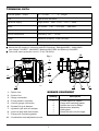
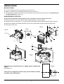
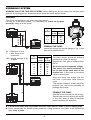
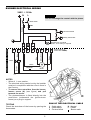
1
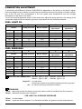
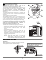
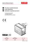
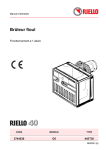
Installation, use and maintenance instructions
Light oil - kerosene burner
One stage operation
CODE
MODEL
TYPE
3747455
G20KI
474T52
2902403 (4) - 01/2008
TECHNICAL DATA
Thermal power – output
95 – 213 kW
–
8 – 18 kg/h
Fuel
Light oil and kerosene
Electrical supply
single phase,
Motor
run current 1.4 A – 2750 rpm – 288 rad/s
Capacitor
5 μF
Ignition transformer
secondary 8 kV – 16 mA
Pump
maximum pressure 14 bar (203 psi)
Absorbed electrical power
0.32 kW
240 V + 10% – 15%
~
50Hz
Q
Burner with CE marking in conformity with EEC Directives: EMC89/336/EEC - 2004/108/EC,
Low Voltage 73/23/EEC - 2006/95/EC, Machines 98/37/EEC and Efficiency 92/42/EEC.
Q
The burner meets protection level of IP 40, EN 60529.
10
Fig. 1
7
6
8
6
4
9
D8067
3
1 – Return line
2
1
BURNER EQUIPMENT
2 – Suction line
3 – Gauge connection
Quantity
4 – Pump pressure regulator
2
1
4
1
1
1
5 – Vacuum gauge connection
6 – Screws fixing air-damper
7 – Hydraulic jack with air-damper
8 – Lock-out lamp and reset button
7 – Flange with insulating gasket
10 – Combustion head adjustment screw
2403
1
Description
Flexible pipes with nipples
Flange with insulating gasket
Screws and nuts for flange
Maintenance assembly
Cable gland
Screw with two nuts for flange
5
Pressure in the combustion
chamber – mbar
FIRING RATE
1.8
1.2
0.6
0
8
90
D5282
10
110
12
130
14
150
16
170
190
18
20 Fuel output - kg/h
210
230 Thermal power - kW
OVERALL DIMENSIONS
Flange
Burner
350
213
118
ø 125
230
298
99
11
45°
160
295
=
99
45°
=
190
41
2403
2
D5283
INSTALLATION
BOILER FIXING
³ Put on the flange (1) the screw and two nuts, (see fig. 2).
³ Widen, if necessary, the insulating gasket holes (5), (see fig. 3).
³ Fix the flange (1) to the boiler door (4) using screws (2) and (if necessary) the nuts (3) interposing the
insulating gasket (5), (see fig. 4).
MAINTENANCE POSITION
Access to the combustion head, diffuser disc / electrodes unit and nozzle, (see fig. 5).
³ Remove the burner out of the boiler, after loosing the fixing nut to the flange.
³ Hook the burner to the flange (1), by removing the combustion head (6) after loosing the fixing screws (7).
³ Remove the diffuser disc-holder assembly (9) from the nozzle-holder (8) after loosing its fixing screw.
³ Screw the nozzle (10).
4
5
Fig. 4
Fig. 3
Fig. 2
2
5
1
D5012
2
1
E9022
D8058
1
5
2
6
4
Fig. 5
3
D8056
D8057
Verify that the installed burner is lightly leaned towards the
button.
(See figure 6).
Fig. 6
The burner is designed to allow entry of the flexible oil-lines
on either side of the burner.
D5572
2403
3
3
HYDRAULIC SYSTEM
WARNING ONLY FOR TWO PIPE SYSTEM: before starting the burner make sure that the return
pipe-line is not clogged: any obstruction would cause the pump seals to break.
WARNING:
The pump is supplied for use with a one pipe system.
For use on a two pipe system, it is necessary to screw the by-pass
screw (A), hang up to the pump.
L meters
max. 4 m
H
D5219
min. 0.1 m
H
meters
I.D.
10 mm
10
20
40
60
20
40
80
100
A
D5199
max. 4 m
H
H = Difference of level.
L = Max. length of the
suction line.
I.D.= Internal diameter of the
oil pipes.
D5220
0.5
1
1.5
2
I. D.
8 mm
PRIMING THE PUMP
Loosen the plug of the vacuum gauge (5, fig. 1) and
wait until the fuel flows out.
L meters
H
meters
0
0.5
1
1.5
2
3
3.5
I. D.
8 mm
I.D.
10 mm
35
30
25
20
15
8
6
100
100
100
90
70
30
20
The pump vacuum should not exceed a
maximum of 0.4 bar (30 cm Hg).
Beyond this limit gas is released from
the oil.
Oil lines must be completely airtight.
The return line should terminate in
the oil tank at the same level as the
suction line; in this case a non-return
valve is not required.
When the return line arrives over the
fuel level, a non-return valve must be
used.
This solution however is less safe than
previous one, due to the possibility of
leakage of the valve.
H
PRIMING THE PUMP:
Start the burner and wait for the priming.
Should lock-out occur prior to the arrival
of the fuel, await at least 20 seconds
before repeating the operation.
X
X
A metal bowl filter with replaceable micronic filter must be fitted in the oil supply pipe.
Check periodically the flexible pipes conditions. Using kerosene, they have to be replaced at
least every 2 years.
2403
4
BURNER ELECTRICAL WIRING
240V
N
~
50Hz
L
WARNING
Do not exchange the neutral with the phase.
Main switch
Neutral
T6A
4
5
6
Blue
Valve
Black
Capacitor
T
Safety thermostat
7
8
9
Terminal block of
control-box 530SE
*
Brown
3
L
White (50V)
2
Limit thermostat
Remote lock-out signal
(240V - 0.5A max.), if required
Blue
1
Brown
Black
CARRIED-OUT IN THE FACTORY
N
T
M
~
Motor
D5228
NOTES
– Wires of 1 mm2 section.
– The electrical wiring carried out by the installer
must be in compliance with the rules in force in
the Country.
– To remove the control-box from the burner,
loosen screw (A) (see figure) and pull
towards the arrow.
– The photoresistance is fitted directly into the
control-box (underneath the ignition-transformer) on a plug-in support.
TESTING
Check the shut-down of the burner by opening the
thermostats.
2403
5
S7029
RUN OF THE ELECTRICAL CABLE
1 - Cable gland
2 - Cable-clamp
3 - Terminal block
N - Neutral
L - Phase
- Burner-earth
COMBUSTION ADJUSTMENT
In conformity with Efficiency Directive 92/42/EEC the application of the burner on the boiler, adjustment and testing must be carried out observing the instruction manual of the boiler, including verification of the CO and CO2 concentration in the flue gases, their temperatures and the average
temperature of the water in the boiler.
To suit the required appliance output, fit the nozzle then adjust the pump pressure, the setting of the
combustion head and the air damper opening in accordance with the following schedule.
FUEL LIGHT OIL
1
2
Nozzle
Pump pressure
Burner output
bar
12
12
12
12
12
12
13
kg/h ± 4%
8.6
9.7
10.7
12.9
15.0
17.2
17.9
GPH
2.00
2.25
2.50
3.00
3.50
4.00
4.00
Angle
60°
60°
60°
60°
60°
60° / 45°
60° / 45°
3
4
Comb. head
adjustment
Set-point
1
1.5
2
2.5
3.5
5
6
Air damper
adjustment
Set-point
3
3.2
3.5
4.3
5.5
6.5
7
3
4
Comb. head
adjustment
Set-point
0.5
1
1.5
2.5
3
3.5
5
6
Air damper
adjustment
Set-point
2.2
2.4
3.0
3.2
4.0
6.0
6.5
7.0
FUEL KEROSENE
GPH
2.75
3.00
3.50
4.00
4.50
5.00
5.50
6.00
1
1
2
Nozzle
Pump pressure
Burner output
bar
8
8
8
8
8
8
8
8
kg/h ± 4%
8.1
8.9
10.3
11.8
13.3
14.8
16.2
17.7
Angle
60°
60°
60°
60°
60°
60°
60° / 45°
60° / 45°
NOZZLES RECOMMENDED: Monarch type R - PLP; Delavan type B - W
Steinen type S - SS ; Danfoss type S - B
Angle 60°: in most cases.
Particularly suitable to avoid flame-detachment during ignition.
45°: for narrow and long combustion-chamber.
2
PRESSURE:
8 bar: the pump leaves the factory set at this value, which is suitable only for kerosene.
10 bar: maximum pressure for kerosene.
FOR LIGHT OIL INCREASE PRESSURE
12 bar: in most cases.
14 bar: improves flame retention; it is therefore suitable for ignitions at low temperatures.
2403
6
3
COMBUSTION HEAD SETTING
This is done when fitting the nozzle, with the blast tube removed. It depends on the output of the
burner and is carried out by rotating the regulating rod, till the terminal plane of the blast tube is level
with the set-point, as indicated in the schedule.
In the sketch below, the combustion head is set for an output of 3.50 GPH at 12 bar (for light oil)
or 5.00 GPH at 8 bar (for kerosene).
The shutter is level with set-point 3.5, as required by the schedule at page 6.
2
Terminal plane of the blast tube
3
1
6
2
5 3 1
Regulating rod
D5676
Blast tube
Shutter
D8068
Combustion head settings indicated in the schedule are valid for most cases.
The setting of the fan output according to the installation should normally be done only through the air
damper. Should one subsequently want to retouch also the setting of the combustion head, with the
burner running, operate on the rod (1) with a 6 mm spanner (2) as follows:
TURN TO THE RIGHT: (SIGN +)
In order to increase the volume of air entering the combustion chamber and thus diminishing its
pressure.
There is a reduction of CO2 and the adhesion of the flame to the air diffuser disc improves.
(Setting advisable for ignitions at low temperatures).
TURN TO THE LEFT: (SIGN –)
In order to reduce the volume of air entering the combustion chamber and thus increasing its pressure. The CO2 improves and the adhesion of the flame to the diffuser tends to reduce. (This setting is
not advisable for ignitions at low temperatures).
In any case do not bring the combustion head setting more than one point away from that indicated in
the schedule. One set-point corresponds to 3 turns of the rod; a hole (3) at its end facilitates counting
the number of turns.
2403
7
4
AIR DAMPER ADJUSTMENT:
1
2
The mobile air damper (1) operated by the jack (2)
assures the complete opening of the air intake.
The regulation of the air-rate is made by adjusting the
fixed air damper (3), after loosing the screws (4). When
the optimal regulation is reached, screw tight the
screws (4) to assure a free movement of the mobile air
damper (1).
3
The settings indicated in the schedule refer to the burner with
its metal cover fitted and the combustion chamber with “zero”
depression.
These regulations are purely indicative.
Each installation however, has its own unpredictable working
conditions: actual nozzle output; positive or negative pressure
in the combustion-chamber, the need of excess air, etc. All
these conditions may require a different air-damper setting.
It is important to take account of the fact that the air
output of the fan differs according to whether the
burner has its metal cover fitted or not.
4
4
D5550
PANEL
Therefore we recommended to proceed as follows:
– adjust the air damper as indicated in the schedule (4);
– mount the cover, simply by means of the upper
screw;
– check smoke number;
– should it become necessary to modify the air
output, remove the cover by loosening the screw,
adjust the air damper, remount the cover and finally
recheck the smoke number.
NOTE: When the burner works at a firing rate
higher than 17 kg/h remove the panel
fitted inside the metal cover (see figure).
D5682
ELECTRODE SETTING
Attention:
Before assembling or removing the nozzle, loosen the
screw (A) and move the electrodes ahead.
MOVE THE ELECTRODE HOLDER
BACKWARDS TO THE END
4 ± 0.3 mm
D5288
A
2403
8
6.5 ± 0.5 mm
START-UP CYCLE
Normal
Lock-out, due to light-failure
Thermostat
Motor
Ignition transformer
Valve
Flame
Lock-out lamp
~ 12s
~ 12s
~ 5s
D5229
ONLY FOR LIGHT OIL
ADJUSTMENTS TO AVOID FLAME DETACHMENT
AT BURNER IGNITION
1)
CORRECT POSITIONING OF THE ELECTRODES
MOVE THE ELECTRODE HOLDER
BACKWARDS TO THE END
4 ± 0.3 mm
D5288
A
2)
NOZZLE: ATOMIZING ANGLE: Choose 60° nozzle.
3)
PUMP - SETTING
6.5 ± 0.5 mm
When the temperature of the light oil decreases below +5 °C, increase the pressure to 14 bar.
4)
COMBUSTION-HEAD SETTING
Regulate the combustion-head one set-point further ahead than indicated in the instructions.
Example: the instructions require to set the combustion-head on set-point 2.5.
Instead, the setting is made on set-point 3.5.
5)
FAN - AIR DAMPER ADJUSTMENT
Adjust the damper, reducing the excess air until the Bacharach number is not near 1.
(i.e. a combustion with the lowest possible excess-air).
2403
9
RIELLO S.p.A.
I-37045 Legnago (VR)
Tel.: +39.0442.630111
http:// www.rielloburners.com
Subject to modifications