1
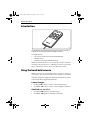
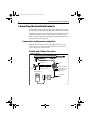
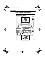
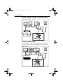
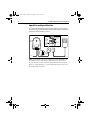
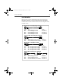
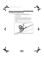
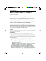
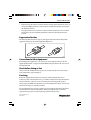
Distributed by
Any reference to Raytheon or
RTN in this manual should be
interpreted as Raymarine.
The names Raytheon and RTN
are owned by the
Raytheon Company.
81197_1.book Page 1 Wednesday, August 1, 2001 11:19 AM
SeaTalk
Autopilot
Hand-held
Remote
Owner’s
Handbook
Document number: 81197-1
Date: July 2001
81197_1.book Page 2 Wednesday, August 1, 2001 11:19 AM
2
SeaTalk Autopilot Hand-held Remote
Autohelm, HSB (High Speed Bus), SailPilot, SeaTalk and SportPilot
are registered trademarks of Raymarine Ltd.
Raymarine, AST (Advanced Steering Technology), AutoAdapt,
AutoLearn, AutoRelease, AutoSeastate, AutoTack, AutoTrim,
FastTrim, GyroPlus, RayGyro, RayPilot and WindTrim are
trademarks of Raymarine Ltd.
Handbook contents © Raymarine Ltd 2001.
81197_1.book Page 3 Wednesday, August 1, 2001 11:19 AM
Owner’s Handbook
3
Introduction
D5678-1
The SeaTalk autopilot hand-held remote (part number A15002) is
suitable for use with all SeaTalk compatible autopilots.
It is supplied with:
•
•
•
6 m (19.5 ft) of cable with a pre-fitted SeaTalk plug
a SeaTalk socket
a bracket for storing the hand-held remote
Note: The hand-held remote is not compatible with older Autohelm
autopilots with an AH prefix (e.g. AH800). If you have any questions
about compatibility, contact your nearest Raymarine dealer.
Using the hand-held remote
Note: You cannot use the hand-held remote to engage or disengage
the autopilot. You will need to do this on the autopilot’s control unit.
When the autopilot is engaged, the hand-held remote allows remote
control of the following autopilot functions:
Course changes
•
•
use -1 and -10 to make 1° and 10° course changes to port
use +1 and +10 to make 1° and 10° course changes to starboard
AutoTack (not SportPilots)
•
•
press -1 and -10 together to AutoTack to port
use +1 and +10 together to AutoTack to starboard
81197_1.book Page 4 Wednesday, August 1, 2001 11:19 AM
4
SeaTalk Autopilot Hand-held Remote
Connecting the hand-held remote
The hand-held remote is connected directly to Raymarine autopilots
or instruments using SeaTalk (the Raymarine data interface system).
The remote is supplied with a waterproof plug and socket that can be
installed anywhere a remote is required. The socket allows you to
make connections directly to the autopilot or SeaTalk instrument, as
described on the following pages.
Connections to Raymarine autopilots
Note: In all of the following cases, the handheld remote can be
connected via any available SeaTalk instrument or control unit
rather than directly to the autopilot.
ST1000+ and ST2000+ tiller pilots
ST1000+ or ST2000+
Supply (0 V)
Socket
Yellow (SeaTalk data)
12 A fuse
Supply (+12 V DC)
Screen (SeaTalk 0 V)
Red (SeaTalk 12 V)
with 5 A fuse
Hand-held remote
SeaTalk cable
(D177)
D5682-1
81197_1.book Page 5 Wednesday, August 1, 2001 11:19 AM
Owner’s Handbook
5
ST1000, ST2000 and ST3000 autopilots
ST1000 or ST2000
Hand-held
remote
Terminal
stripes
Screen
(SeaTalk
ground)
Red
(+12 V)
Yellow
(SeaTalk
data)
12V
Yellow
Yellow
Screen
Screen
Red
5A Fuse
ST3000
D177 cable
(not supplied)
Red
Hand-held
remote
12V
Screen
(SeaTalk
ground)
Yellow
(SeaTalk
data)
Terminal
stripes
Red
(+12 V)
D5683-1
81197_1.book Page 6 Wednesday, August 1, 2001 11:19 AM
6
SeaTalk Autopilot Hand-held Remote
ST4000+ and ST5000+ autopilots
ST4000+ and ST5000+ control units have two parallel SeaTalk ports.
You can connect the hand-held remote to either of these ports.
ST4000+ or ST5000+
Screen
(SeaTalk
ground)
Yellow
(SeaTalk
data)
Terminal
stripes
Red
(+12 V)
with
5 A fuse
Hand-held remote
12 V
D5684-1
Note: If any other SeaTalk instruments are connected to the ST4000
or ST5000 control units, the red wire (+12 V) must be connected to a
separate 12 V supply fitted with a 5 A fuse. It should NOT be
connected to the control unit.
ST4000 and ST5000 autopilots
The main difference with older ST4000 and ST5000 control units is
that the SeaTalk connections at the control unit will require spades
(part number: D211).
ST4000 or ST5000
D177
(Not supplied)
5A
fuse
RYS
Screen
(SeaTalk
ground)
Yellow
(SeaTalk
data)
Terminal
stripes
Red
(+12 V)
Hand-held remote
12 V
D5685-1
81197_1.book Page 7 Wednesday, August 1, 2001 11:19 AM
Owner’s Handbook
7
ST6000+, ST6001+, ST7000+ and ST7001+ pilots
ST6000+, ST6001+, ST7001+ or ST7000+
ST6001+/ST6000+
150/400 Course Computer
Hand-held remote
ST7001+/ST7000+
Screen
(SeaTalk
ground)
Yellow
(SeaTalk
data)
Terminal
stripes
Red
(+12 V)
D5687-1
ST6000 and ST7000 autopilots
The main difference when connecting older ST6000 and ST7000
autopilots is that you will need a SeaTalk cable with round plugs.
ST6000 or ST7000
ST6000
Hand-held remote
ST7000
100/300 Course Computer
Screen
(SeaTalk
ground)
Yellow
(SeaTalk
data)
Terminal
stripes
Red
(+12 V)
D5688-1
81197_1.book Page 8 Wednesday, August 1, 2001 11:19 AM
8
SeaTalk Autopilot Hand-held Remote
SportPilot and SportPilot Plus
To connect the hand-held remote to the SportPilot you will need to
purchase an appropriate SeaTalk interface cable (D229). The red core
should also be fitted with a 5 A fuse.
SportPilot or SportPilot Plus
Screen
(SeaTalk
ground)
Yellow
(SeaTalk
data)
Terminal
stripes
Red
(+12 V)
YSR
5A
fuse
12 V
D5689-1
Note: If you intend to locate the remote close to the SportPilot, the
SportPilot’s power cable has two additional wires (yellow and
screen) that you can use to connect the SeaTalk socket to the pilot.
However, a fused positive (+) connection from the power source to
the socket will be required.
81197_1.book Page 9 Wednesday, August 1, 2001 11:19 AM
Owner’s Handbook
9
SeaTalk cables
Because you can use the hand-held remote with a wide range of
Raymarine autopilots, you will need to purchase the appropriate
SeaTalk cable to connect the hand-held remote to the autopilot via the
SeaTalk system.
Extension cables - flat moulded plugs at each end
Part no.
D284
D285
D286
D287
D288
Type
Flat moulded plugs at each end
Flat moulded plugs at each end
Flat moulded plugs at each end
Flat moulded plugs at each end
Flat moulded plugs at each end
Length
1 m (3 ft 3 in)
3 m (9 ft 10 in)
5 m (16 ft 5 in)
9 m (29 ft 6 in)
20 m (65 ft 6 in)
Conversion cables - flat moulded plug to round plug
Part no.
D187
D188
Type
Flat moulded plug to male round plug
Flat moulded plug to female round plug
Length
0.15 m (6 in)
0.3 m (12 in)
Extension cables - round plugs at each end
Part no.
D124
D125
D126
D154
Type
Male round plug to female round plug
Male round plug to female round plug
Male round plug to female round plug
Male round plug to female round plug
Length
1 m (3 ft 3 in)
3 m (9 ft 10 in)
6 m (19 ft 8 in)
9 m (29 ft 6 in)
Interface cables - bare wires at one or both ends
Part no.
D229
D179
D181
D177
Type
Flat moulded plug to bare wires
Male round plug to bare wires
Female round plug to bare wires
Bare wires at both ends, in-line 5 A fuse
Length
1 m (3 ft 3 in)
3 m (9 ft 10 in)
3 m (9 ft 10 in)
3 m (9 ft 10 in)
D5681-1
81197_1.book Page 10 Wednesday, August 1, 2001 11:19 AM
10
SeaTalk Autopilot Hand-held Remote
Installing the SeaTalk socket
1. Apply the template onto the bulkhead as required.
2. Drill the 18 mm (45/64 in) clearance hole and the two 2.5 mm
(3/32 in) pilot holes.
3. Remove the template.
4. Cut and strip the SeaTalk cable (not supplied: see page 9).
5. Pass the cables through the bulkhead and wire to the socket,
making sure the wires are connected to the correct pins.
6. Use the two self-tapping screws to attach the socket to the
bulkhead.
7. Secure the cables at regular intervals using suitable cable ties.
D5691-1
Note: Should you require any spare parts, please refer to the spares
list on page 12.
81197_1.book Page 11 Wednesday, August 1, 2001 11:19 AM
Owner’s Handbook
11
Installing the hand-held remote bracket
The hand- held remote is supplied with a bulkhead-mounted storing
bracket. This bracket should be attached to a convenient bulkhead
using the 3 double-sided adhesive pads provided.
D5692-1
Note: Spare bulkhead brackets, part number D224, can be ordered
from your dealer.
81197_1.book Page 12 Wednesday, August 1, 2001 11:19 AM
12
SeaTalk Autopilot Hand-held Remote
Fault Finding
All Raymarine products are subjected to comprehensive test
procedures prior to packaging and shipment. In the unlikely event
that a fault does occur, the following check list should help to cure any
problem.
LED not illuminated
•
•
No power supply – check the red lead for +12 V.
Check the remote socket connections and the security of all
SeaTalk connectors and cables.
No exchange of information between the hand held remote
and the autopilot
•
Open circuit SeaTalk bus – check the yellow (data) lead for
fluctuating voltage.
Check the remote socket connections and the security of all
SeaTalk connectors and cables.
•
Unit does not operate autopilot
•
Autopilot not in Auto mode.
Note: No audible beep will be heard when operating the hand held
remote.
Spares List
The following items may be purchased from your local Raymarine
dealer should you need them.
Part Number
Description
D161
SeaTalk socket assembly only
D162
Plug and socket assembly
D211
Spade connector kit for ST4000 and ST5000
D224
Hand-held remote storing bracket
D330
Socket O-ring
81197_1.book Page 13 Wednesday, August 1, 2001 11:19 AM
Owner’s Handbook
13
SeaTalk socket template
Drill 2.5 mm (3/32 inch)
diameter hole (2 positions)
Drill 18 mm (23/32 inch)
diameter hole
D5658-1
81197_1.book Page 14 Wednesday, August 1, 2001 11:19 AM
14
SeaTalk Autopilot Hand-held Remote
Raymarine EMC Guidelines
EMC Installation & Service Guidelines
IMPORTANT NOTE
All Raymarine equipment and accessories are designed to the best industry standards for
use in the leisure marine environment.
When powered up, all electrical equipment produces electromagnetic fields. These can
cause adjacent pieces of electrical equipment to interact with one another, with a
consequent adverse effect on operation. In order to minimise these effects and enable you
to get the best possible performance from your Raymarine equipment, these guidelines are
provided to enable you to ensure minimum interaction between different items of
equipment, i.e. ensure optimum Electromagnetic Compatibility (EMC).
The design and manufacture of Raymarine equipment and accessories conform to the
appropriate EMC standards, but correct installation is required to ensure that performance
is not compromised. Although every effort has been taken to ensure that they will perform
under all conditions, it is important to understand what factors could affect the operation of
the product. Please keep this document for future reference.
Safety
Some products generate high voltages, so never handle the cables/connectors when power
is being supplied to the equipment.
Installation
These guidelines describe the conditions for optimum EMC performance, but it is
recognised that it may not be possible to meet all of these conditions in all situations. To
ensure the best possible conditions for EMC performance within the constraints imposed
by any location, always ensure the maximum separation possible between different items
of electrical equipment.
For optimum EMC performance, it is recommended that wherever possible:
• Raymarine equipment and cables connected to it are:
• At least 1 m (3 ft) from any equipment transmitting or cables carrying radio signals
e.g. VHF radios, cables and antennas. In the case of SSB radios, the distance
should be increased to 2 m (7 ft).
• More than 2 m (7 ft) from the path of a radar beam. A radar beam can normally be
assumed to spread 20 degrees above and below the radiating element.
• The equipment is supplied from a separate battery from that used for engine start.
Voltage drops below 10 V in the power supply to our products, and starter motor
transients, can cause the equipment to reset. This will not damage the equipment, but
may cause the loss of some information and may change the operating mode.
Raymarine EMC Guidelines
•
•
Raymarine specified cables are used at all times. Cutting and rejoining these cables can
compromise EMC performance and so must be avoided unless doing so is detailed in
the installation manual.
If a suppression ferrite is attached to a cable, this ferrite should not be removed. If the
ferrite needs to be removed during installation it must be reassembled in the same
position.
Suppression Ferrites
The following illustration shows typical cable suppression ferrites fitted to Raymarine
equipment. Always use the ferrites supplied by Raymarine.
D3548-2
Connections to Other Equipment
If your Raymarine equipment is to be connected to other equipment using a cable not
supplied by Raymarine, a suppression ferrite MUST always be fitted to the cable close to
the Raymarine unit.
Check Before Going to Sea
Always check the installation before going to sea to make sure that it is not affected by
radio transmissions, engine starting etc.
Servicing
Raymarine equipment should be serviced only by authorised Raymarine service
technicians. They will ensure that service procedures and replacement parts used will not
affect performance. There are no user serviceable parts in any Raymarine product.
Always report any EMC related problem to your nearest Raymarine dealer. We use such
information to improve our quality standards.
In some installations it may not be possible to prevent equipment from being affected by
external influences. In general this will not damage the equipment but it can lead to
spurious resetting action, or momentarily may result in faulty operation.
Document number: 84018-5
Date: May 2001
81197_1.book Page 1 Wednesday, August 1, 2001 11:19 AM
Limited Warranty Certificate
Raymarine warrants each new Light Marine/Dealer Distributor Product to be of good materials and
workmanship, and will repair or exchange any parts proven to be defective in material and
workmanship under normal use for a period of 2 years/24 months from date of sale to end user, except
as provided below.
Defects will be corrected by Raymarine or an authorized Raymarine dealer. Raymarine will, except
as provided below, accept labor cost for a period of 2 years/24 months from the date of sale to end user.
During this period, except for certain products, travel costs (auto mileage and tolls) up to 100 round
trip highway miles (160 kilometres) and travel time of 2 hours, will be assumed by Raymarine only
on products where proof of installation or commission by authorized service agents, can be shown.
Warranty Limitations
Raymarine Warranty policy does not apply to equipment which has been subjected to accident, abuse
or misuse, shipping damage, alterations, corrosion, incorrect and/or non-authorized service, or
equipment on which the serial number has been altered, mutilated or removed.
Except where Raymarine or its authorized dealer has performed the installation, it assumes no
responsibility for damage incurred during installation.
This Warranty does not cover routine system checkouts or alignment/calibration, unless required by
replacement of part(s) in the area being aligned.
A suitable proof of purchase, showing date, place, and serial number must be made available to
Raymarine or authorized service agent at the time of request for Warranty service.
Consumable items, (such as: Chart paper, lamps, fuses, batteries, styli, stylus/drive belts, radar mixer
crystals/diodes, snap-in impeller carriers, impellers, impeller bearings, and impeller shaft) are
specifically excluded from this Warranty.
Magnetrons, Cathode Ray Tubes (CRT), TFT Liquid Crystal Displays (LCD) and cold cathode
fluorescent lamps (CCFL), hailer horns and transducers are warranted for 1 year/12 months from date
of sale. These items must be returned to a Raymarine facility.
All costs associated with transducer replacement, other than the cost of the transducer itself, are
specifically excluded from this Warranty.
Overtime premium labor portion of services outside of normal working hours is not covered by this
Warranty.
Travel cost allowance on certain products with a suggested retail price below $2500.00 is not
authorized. When/or if repairs are necessary, these products must be forwarded to a Raymarine
facility or an authorized dealer at owner’s expense will be returned via surface carrier at no cost to the
owner.
Travel costs other than auto mileage, tolls and two (2) hours travel time, are specifically excluded on
all products. Travel costs which are excluded from the coverage of this Warranty include but are not
limited to: taxi, launch fees, aircraft rental, subsistence, customs, shipping and communication
charges etc. Travel costs, mileage and time, in excess to that allowed must have prior approval in
writing.
TO THE EXTENT CONSISTENT WITH STATE AND FEDERAL LAW:
(1) THIS WARRANTY IS STRICTLY LIMITED TO THE TERMS INDICATED HEREIN, AND
NO OTHER WARRANTIES OR REMEDIES SHALL BE BINDING ON RAYMARINE
INCLUDING WITHOUT LIMITATION ANY WARRANTIES OF MERCHANTABLE OR
FITNESS FOR A PARTICULAR PURPOSE.
(2) Raymarine shall not be liable for any incidental, consequential or special (including punitive or
multiple) damages.
All Raymarine products sold or provided hereunder are merely aids to navigation. It is the
responsibility of the user to exercise discretion and proper navigational skill independent of any
Raymarine equipment.
Document number: 84064-8
April 2001
81197_1.book Page 2 Wednesday, August 1, 2001 11:19 AM
Factory Service Centers
United States of America
UK, Europe, Middle East, Far East
Raymarine Inc
22 Cotton Road, Unit D
Nashua, NH 03063-4219, USA
Raymarine Ltd
Anchorage Park, Portsmouth
PO3 5TD, England
Telephone: +1 603 881 5200
Fax: +1 603 864 4756
www.raymarine.com
Telephone: +44 (0)23 9269 3611
Fax: +44 (0)23 9269 4642
www.raymarine.com
Sales & Order Services
Telephone: +1 800 539 5539 Ext. 2333 or
+1 603 881 5200 Ext. 2333
Customer Support
Telephone: +44 (0)23 9271 4713
Fax: +44 (0)23 9266 1228
Technical Support
Telephone: +1 800 539 5539 Ext. 2444 or
+1 603 881 5200 Ext. 2444
Email: [email protected]
Email: [email protected]
Product Repair Center
Telephone: +1 800 539 5539 Ext. 2118
Stick barcode label here
Purchased from
Purchase date
Dealer address
Installed by
Installation date
Commissioned by
Commissioning date
Owner’s name
Mailing address
This portion should be completed and retained by the owner.