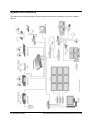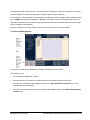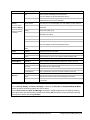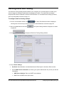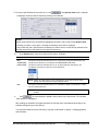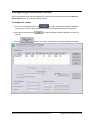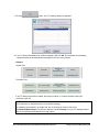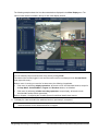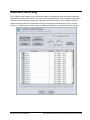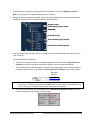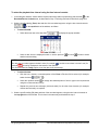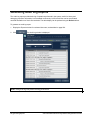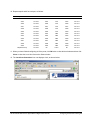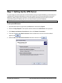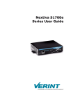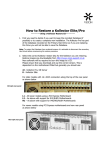
1
XX112-36-00
Vicon Industries Inc. does not warrant that the functions contained in this equipment will meet your
requirements or that the operation will be entirely error free or perform precisely as described in the
documentation. This system has not been designed to be used in life-critical situations and must not be
used for this purpose.
Copyright © 2009 Vicon Industries Inc. All rights reserved.
Product specifications subject to change without notice.
ViconNet, Kollector, I-ONYX and their logos are registered trademarks of Vicon Industries Inc.
Vicon and its logo are registered trademarks of Vicon Industries Inc.
Windows is a trademark of Microsoft Corp.
VICON INDUSTRIES INC., 89 ARKAY DRIVE, HAUPPAUGE, NEW YORK 11788
TEL: 631-952-CCTV (2288) FAX: 631-951-CCTV (2288) TOLL FREE: 800-645-9116
24-Hour Technical Support: 800-34-VICON (800-348-4266)
UK: 44/(0) 1489-566300 WEB: www.vicon-cctv.com
Vicon Part No. 8009-8112-36-00 Section 1 Rev 909
Software Manual
Kollector Hybrid Network Digital Video
Recorder
Important Notice
This Software Manual is delivered subject to the following conditions and restrictions:
Φ
This Manual contains proprietary information belonging to Vicon. Such information is supplied solely for
the purpose of assisting explicitly and properly authorized users of the ViconNet system.
Φ
No part of its contents may be used for any other purpose, disclosed to any person or firm or reproduced
by any means, electronic or mechanical, without the express prior written permission of Vicon.
Φ
The text and graphics are for the purpose of illustration and reference only. The specifications on which
they are based are subject to change without notice.
Φ
The software described in this Manual is furnished under a license. The software may be used or copied
only in accordance with the terms of that agreement.
Φ
Information in this Manual is subject to change without notice. Corporate and individual names and data
used in examples herein are fictitious unless otherwise noted.
Copyright ©2009 Vicon Industries Inc. All rights reserved.
ViconNet, Kollector and I-Onyx are registered trademarks of Vicon Industries Inc.
Other company and brand products and service names are trademarks or registered trademarks of their
respective holders.
XX112-36-00 Rev 909 Kollector Hybrid Network Digital Video Recorder
Important Notice • i
About This Manual
The Kollector Software Manual is comprised of the following chapters:
Φ
Chapter 1, Introducing ViconNet, introduces the main concepts and system architecture of the
ViconNet system.
Φ
Chapter 2, Getting to Know ViconNet, describes the main ViconNet application windows and their
functionality.
Φ
Chapter 3, Configuring the ViconNet System, describes all available configuration functions in the
ViconNet system, including system setup and creating macros and schedules.
Φ
Chapter 4, Viewing and Listening to Live Video/Audio, describes the mandatory and optional tasks
involved in viewing and listening to live video and audio.
Φ
Chapter 5, Recording Live Video/Audio, describes the manual and automatic processes for recording
live video and audio.
Φ
Chapter 6, Playing Back Recorded Video/Audio, describes the process for playing back recorded
video and audio.
Φ
Chapter 7, Managing Macros and Schedules, describes how manage and work with macros and
schedules in the ViconNet system.
Φ
Chapter 8, Generating Reports, describes how to generate different types of reports available in the
ViconNet system.
Φ
Chapter 9, Printing/Exporting Frames and Creating Video Clips, describes how to print out or export
selected frames from Playback, and to create video clips from selected playback segments.
Φ
Appendix A, Configuring your Personal Firewall, describes how to configure your firewall to protect
your ViconNet system.
Φ
Appendix B, Configuring the Network, describes how to configure network adaptors and DHCP.
Φ
Appendix C, Setting Up a VPN Service, presents an example of how to setup a Virtual Private Network
(VPN) service (server and client) for the ViconNet application.
Φ
Appendix D, Using Video Analytics, explains how to use the integrated video analytics with the
ViconNet system.
Φ
Appendix E, Running ViconNet as a Service, explains how to use ViconNet as a service configurator
running on Windows, without the GUI.
This manual covers the entire Kollector line, ViconNet version 5.6, including the Kollector Strike and Kollector
Force and Kollector Elite, Pro and Lite upgraded to ViconNet version 5.6.
ii • About This Manual
XX112-36-00 Rev 909 Kollector Hybrid Network Digital Video Recorder
Table of Contents
CHAPTER 1, INTRODUCING VICONNET ...........................................................................1
What Is ViconNet? ..........................................................................................................................................2
What Is the Kollector?....................................................................................................................................2
How Does ViconNet Work? ...........................................................................................................................2
Frequently Asked Questions.........................................................................................................................3
ViconNet Products .........................................................................................................................................6
UPS System Requirements ...........................................................................................................................9
System Architecture.....................................................................................................................................10
Front Panel Indicators..................................................................................................................................11
CHAPTER 2, GETTING TO KNOW VICONNET ................................................................13
Logging In .....................................................................................................................................................14
Main Window.................................................................................................................................................15
Main Window Toolbar .................................................................................................................................17
Video and Recording Elements ..................................................................................................................19
Playback Controls .......................................................................................................................................35
Other Controls.............................................................................................................................................36
Navigator Window ........................................................................................................................................37
Navigator Window Toolbar .........................................................................................................................39
Navigator Area ............................................................................................................................................39
Recorded Device Contents.........................................................................................................................42
Main Window Display Location Area ..........................................................................................................46
Functions and Settings ...............................................................................................................................48
Alarm Window...............................................................................................................................................51
Logging Out, Exiting or Shutting Down .....................................................................................................54
Logging Out ................................................................................................................................................54
Exiting ViconNet..........................................................................................................................................55
Shutting Down or Restarting.......................................................................................................................55
Watchdog ......................................................................................................................................................55
CHAPTER 3, CONFIGURING THE VICONNET SYSTEM .................................................57
Accessing the Configuration Functions ....................................................................................................59
Modifying the System Configuration..........................................................................................................61
Configuring the Network Setup...................................................................................................................61
Configuring/Modifying Cameras, Microphones, Sensors and Relays ........................................................68
Configuring/Modifying PTZ Controls...........................................................................................................77
Using Reset Nucleus....................................................................................................................................78
XX112-36-00 Rev 909 Kollector Hybrid Network Digital Video Recorder
Table of Contents • iii
Using the Central Failure Notification (CFN) Mechanism ........................................................................80
Configuring the Central Failure Notification (CFN) Display.....................................................................82
Configuring System Authorizations ...........................................................................................................84
Defining Groups ..........................................................................................................................................84
Defining Users ............................................................................................................................................87
Configuring Site Authorization ...................................................................................................................90
Configuring Auto Login ...............................................................................................................................94
Configuring Storage Database Utilities......................................................................................................96
Configuring Storage Locations ...................................................................................................................96
Clearing Video and Audio Storage Locations...........................................................................................100
Configuring System Authentication .........................................................................................................102
Defining Device Groups and Group Sets.................................................................................................103
Creating a Group Set................................................................................................................................103
Configuring Manual Recording and Video Quality .................................................................................108
Configuring Automatic Recording............................................................................................................110
Configuring Auto/Manual FPS (Frames Per Second) .............................................................................113
Using the Recording Verification System (RVS).....................................................................................116
Creating Macros .........................................................................................................................................121
Creating Regular Macros..........................................................................................................................121
Creating Matrix Macros.............................................................................................................................130
Activating Relays in Macros......................................................................................................................132
Defining Email and Texting .......................................................................................................................133
Setting Video and Audio Priority ..............................................................................................................135
Picture Quality and FPS Priority ...............................................................................................................135
Configuring Alarm Events .........................................................................................................................139
Defining Alarm Setup Links ......................................................................................................................140
Setting Pre/Post Alarms............................................................................................................................152
Video Analytics...........................................................................................................................................156
Configuring Events Management .............................................................................................................157
Creating Schedules ....................................................................................................................................166
Configuring Low Bandwidth .....................................................................................................................171
Restoring and Backing Up System Settings ...........................................................................................172
Configuring an External Control...............................................................................................................173
Activating a Control...................................................................................................................................175
Defining Site Maps and Map Sets .............................................................................................................177
Creating a Map Set ...................................................................................................................................177
I-Onyx 9xx and Third Party Cameras........................................................................................................186
I-Onyx 9xx and Third Party Format...........................................................................................................189
iv • Table of Contents
XX112-36-00 Rev 909 Kollector Hybrid Network Digital Video Recorder
Using the Language Translation Utility (LTU) .........................................................................................190
Creating a Library File ..............................................................................................................................190
Implementing the Translation in the ViconNet Application .......................................................................192
Viewing the Settings Summary.................................................................................................................194
Display Settings..........................................................................................................................................195
Registering Your System...........................................................................................................................196
CHAPTER 4, VIEWING AND LISTENING TO LIVE VIDEO/AUDIO ................................199
Overview......................................................................................................................................................200
Viewing and Listening Workflow ..............................................................................................................201
Step 1: Selecting the Display Mode..........................................................................................................202
Step 2: Selecting Cameras and Microphones .........................................................................................204
Step 3: Controlling the Picture..................................................................................................................208
Step 4: Zooming the Video Display ..........................................................................................................209
Step 5: Operating a PTZ Camera ..............................................................................................................210
CHAPTER 5, RECORDING LIVE VIDEO/AUDIO ............................................................213
Overview......................................................................................................................................................214
Recording Live Video/Audio (On-Demand) .............................................................................................215
Automatic Recording .................................................................................................................................218
Automatic Scheduled Recording..............................................................................................................219
Alarm Recording.........................................................................................................................................220
CHAPTER 6, PLAYING BACK RECORDED VIDEO/AUDIO...........................................221
Overview......................................................................................................................................................222
Playback Workflow.....................................................................................................................................223
Step 1: Selecting Recorded Video/Audio.................................................................................................224
Step 2: Changing the Main Window Display Location ...........................................................................228
Step 3: Selecting the Playback Time Interval ..........................................................................................229
Step 4: Selecting the Playback Start Time...............................................................................................231
Step 5: Displaying Recorded Video/Audio Content................................................................................234
Step 6: Playing Back from a Selected Camera/Microphone ..................................................................236
Quick Playback .........................................................................................................................................237
Museum Search ..........................................................................................................................................240
Defining ROIs............................................................................................................................................243
How Episodes Are Determined.................................................................................................................244
Video Analytics...........................................................................................................................................245
Creating Archives.......................................................................................................................................247
CHAPTER 7, MANAGING MACROS AND SCHEDULES ...............................................251
XX112-36-00 Rev 909 Kollector Hybrid Network Digital Video Recorder
Table of Contents • v
Creating Macros and Schedules...............................................................................................................252
Working with Macros .................................................................................................................................252
CHAPTER 8, GENERATING REPORTS..........................................................................255
Overview......................................................................................................................................................256
Saving Logs ..............................................................................................................................................256
Opening the Reports Window ...................................................................................................................259
Generating Device Status Reports ...........................................................................................................260
Generating Alarm History Reports ...........................................................................................................261
Generating Recording Status Reports .....................................................................................................265
Generating Audit Log Reports ..................................................................................................................266
Generating RVS Log Reports....................................................................................................................268
Generating CFN Log Reports....................................................................................................................269
Generating Event History Log Reports ....................................................................................................270
CHAPTER 9, PRINTING/EXPORTING FRAMES AND CREATING VIDEO CLIPS.........277
Printing Frames ..........................................................................................................................................278
Exporting Frames .......................................................................................................................................279
Creating Video Clips ..................................................................................................................................280
APPENDIX A, CONFIGURING THE PERSONAL FIREWALL ........................................281
Disabling the Personal Firewall ................................................................................................................284
Opening the RDP Option (Port) Within the Personal Firewall ...............................................................285
APPENDIX B, CONFIGURING THE NETWORK .............................................................287
Configuring the Network Adapter.............................................................................................................288
Configuring a Network with DHCP ...........................................................................................................289
APPENDIX C, SETTING UP A VPN SERVICE ................................................................291
Step 1: Setting Up the VPN Server ...........................................................................................................292
Step 2: Setting Up the Dialup Connection ...............................................................................................295
Step 3: Selecting the VPN Network Adapter............................................................................................298
Step 4: Setting Up the VPN Network ........................................................................................................299
Troubleshooting .........................................................................................................................................300
APPENDIX D, USING VIDEO ANALYTICS .....................................................................301
APPENDIX E, RUNNING VICONNET AS A SERVICE ....................................................303
vi • Table of Contents
XX112-36-00 Rev 909 Kollector Hybrid Network Digital Video Recorder
XX112-36-00 Rev 909 Kollector Hybrid Network Digital Video Recorder
Table of Contents • vii
Chapter 1
Introducing ViconNet
This chapter introduces the ViconNet system and includes the following sections:
•
What Is ViconNet?, page 1, provides a brief overview of the ViconNet system.
•
What Is the Kollector?, page 2, describes the Kollector recorders.
•
How Does ViconNet Work?, page 2, describes overall functionality of the ViconNet system.
•
ViconNet Products, page 6, provides a brief description of the main ViconNet components and the
software options available.
•
UPS System Requirements, page 9, outlines the main ViconNet system requirements.
•
System Architecture, page 10, illustrates the ViconNet system architecture.
•
Front Panel Indicators, page 11, explains the Kollectors front panel’s LED indicators.
What Is ViconNet?
ViconNet is a complete video surveillance solution that may include a variety of workstations, recording and
storage devices, cameras, monitors, encoders and decoders. All these are connected over an Ethernet
network and communicate with each other via ViconNet management software. ViconNet is a fully scalable
solution, appropriate for small or large installations and can make use of a variety of transmission methods,
including IP. All devices in a ViconNet network can communicate with each other, which enables tremendous
control and flexibility regarding how and from where surveillance video is monitored and managed. For
example, a global corporation with many sites can merge its surveillance operations into one ViconNet
system, with cameras at one location providing video that can be viewed, reviewed and stored on the other
side of the world. Various authority levels may be assigned to ViconNet users at each location, allowing for
different levels of access and control of the system.
ViconNet version 5 provides an open platform that allows integration with IP cameras, encoders and IP edge
devices, including megapixel cameras, from numerous industry-leading manufacturers. Additionally, the
ViconNet interface has integrated ViconNet VI video intelligence. It also allows integration with leading access
control systems; these integrations may require additional 3rd party software. With version 5, there is support
for the ViconNet GUI on a widescreen monitor (16:9 and 16:10). In addition, ViconNet 5 can be executed as a
service enabling to use all ViconNet abilities in server-like environments.
XX112-36-00 Rev 909 Kollector Hybrid Network Digital Video Recorder
Introducing ViconNet • 1
What Is the Kollector?
The Kollector is a family of 16-channel hybrid network digital video recorders powered by a software platform
called ViconNet. This manual includes the Kollector Strike, Kollector Force, and Kollector Elite, Pro and Lite
that have been upgraded to version 5.6. The introduction of ViconNet version 5.6 allows all models of the
Kollector recorder to record video and audio from local analog inputs as well as video and audio streamed
over the network from other recorders, encoders/decoders and IP cameras, providing outstanding flexibility.
The Kollector Force and Strike are H.264 ready (when H.264 version becomes available).
Note: In this manual, any features for the Kollector Force are relevant to Kollector Elite and Pro units
upgraded to version 5.6 software; Kollector Strike features pertain to Kollector Lite units upgraded to version
5.6.
The Kollector utilizes two different video compression methods, selectable based on the application’s
requirements:
•
Normal: Optimized MPEG4. A proprietary compression algorithm developed by Vicon that produces
outstanding video quality and extended recording durations.
•
Full: JPEG. Standard full-frame compression for use in situations that cannot use motion compensation
compression.
The Kollector has a recording rate based on system settings and video scene content. It distributes its own
collected video to each client, or to another Workstation, upon request over a network. Each Workstation is
capable of simultaneously viewing 16 cameras while supporting archiving, system configuration and the
control of pan/tilt/zoom drives. Sixteen audio inputs are available for microphone connection.
The Kollector includes full 16-channel simultaneous record and playback, an integrated GUI for system
configuration, playback and recording on a SVGA monitor, and support for NTSC/EIA and PAL/CCIR video
cameras. In addition, it supports WAN/Internet connectivity for remote video and audio transmission.
How Does ViconNet Work?
The idea behind the ViconNet system architecture is relatively simple -enable full flexibility and minimize
system complexity for the users. The ViconNet system configured on a network can deal with numerous
Workstations. This means that users can use their individual Workstations to view different cameras and
microphones from all ViconNet devices that transmit video/audio, such as the Kollector family of DVRs, IP
camera, encoder, decoder and so on within the system simultaneously. The data that can be viewed includes
all live data as well as recorded data.
In addition, users can perform recording operations on their individual Workstations within the ViconNet
system according to their requirements. Depending on the assigned authority level, each user can view
everything that is configured in the system at any time.
Connection to transmitters is not limited only to local area networks (LANs), but is also possible for wide area
networks (WANs) and the Internet.
2 • Introducing ViconNet
XX112-36-00 Rev 909 Kollector Hybrid Network Digital Video Recorder
Frequently Asked Questions
The following set of questions and answers have been created to help customers get the most out of the
potential of ViconNet. Each question is a real-life situation answered by Vicon’s outstanding technical support
group.
•
What parameters should be considered when calculating storage and bandwidth?
The ViconNet devices, much like other IP-based video systems, send the video over the network to a NVR or
store it on DVR drives. This data is influenced by a few major parameters:
• Compression method – What compression is being used? ViconNet Normal/Full, M-JPEG, MPEG-4,
H.264 are options with ViconNet or with 3rd party cameras.
• Frame rate – More frames per second will require more bandwidth and more storage.
• Picture resolution – The picture resolution (CIF to 4 CIF and Megapixel range) has significant
influence on the storage, higher resolution = more storage.
• Motion type – Unless you are using M-JPEG, the amount of motion in the picture will affect the
amount of data.
Make sure to obtain the storage calculator for ViconNet or the 3rd party camera you are using, and calculate
the different types of cameras separately. When calculating bandwidth, estimate the “worse-case” to ensure
your network can carry the traffic.
•
What are the options for storage?
When using a DVR or an NVR, ViconNet offers several storage options:
• Internal storage – Hard drives in the DVR or the NVR.
• Internal RAID – Hard drives in the DVR (Kollector Force) or NVR (VN-NVR Shadow) configured in a
RAID 5 array.
• External RAID – Using SCSI card in the DVR/NVR, an external RAID unit can be attached and
provide more storage and RAID protection.
• NAS – Although ViconNet can send video to a mapped drive (NAS) on the network, we recommend
that this will not be used as the main storage method; it utilizes network resources and therefore
Vicon can not estimate their performance.
• SAN – Vicon offers SAN solutions (iSCSI) for the DVR/NVR, utilizing a dedicated storage network
and large storage arrays.
•
Does ViconNet require specific ports to be open in the firewall?
Yes, ViconNet uses ports 4354 – 4359 both in TCP and UDP. These ports will be automatically open
when ViconNet is installed.
•
What network protocols does ViconNet use and support?
ViconNet devices use TCP Unicast protocol to communicate and send video. ViconNet does support
Multicast-based video from several cameras, including its I-Onyx cameras. The support of Multicast
depends on the camera.
•
Does ViconNet support video analytics?
Yes, ViconNet VI is Vicon’s video analytics solution. When ViconNet VI is installed, you can configure
ViconNet to receive alarms and indications of the analytics detections.
•
Is there a limitation to the number of cameras ViconNet can handle?
XX112-36-00 Rev 909 Kollector Hybrid Network Digital Video Recorder
Introducing ViconNet • 3
No, ViconNet can handle an unlimited number of cameras through an unlimited number of DVRs, NVRs,
encoders and IP cameras. The system needs to be designed in a way that will allow it to function
properly.
•
Is there a license per camera connected?
ViconNet devices do not require per-camera license; in cases where 3rd party cameras are utilized, a
license fee will be charged to allow connecting this camera to the system.
•
Do I have to have a DVR in the system?
No, ViconNet offers many devices to choose from; you can build a fully functional system with cameras
and NVRs, without using a DVR at all. You can, however, use DVRs, NVRs, encoders and IP cameras in
the same system, which allows you to choose the best solution for different camera types and still
manage it from the same interface.
•
Can I buy ViconNet software without ViconNet hardware?
Yes, Vicon offers the ViconNet software packages if you choose to install on your own PC hardware. This
applies to the PC software and not the DVRs, which are hardware devices.
•
Is there any advantage in buying hardware from Vicon?
Yes, Vicon offers a range of hardware components that have one thing in common; they were built and
certified to work with the ViconNet software! Buying these components ensures the 3 year warranty from
Vicon, single point of contact for support and maximum compatibility between system components.
•
Does Vicon offer a software developer’s kit for custom applications?
There is no SDK, but there is an API. The API for the ViconNet DVR series of products is a controlled
document requiring a non-disclosure agreement to be signed prior to release. All requests for the API
should be directed to your Vicon sales representative. All technical support questions regarding the API
should be directed to the ViconNet engineers at [email protected].
•
Can the network bandwidth be increased to allow for more information (frame rates)?
The recorder will always use the maximum bandwidth available, but it will sacrifice FPS in order to
maintain the selected quality within that available bandwidth.
•
Can we set up presets or tours through a recorder for our PTZ domes?
Any dome feature is accessible from any recorder or Workstation, based on the logged in user’s
authorization profile and on whether PTZ drivers are installed and configured.
•
Is there a priority level available for PTZ domes on a recorder? If two people are looking at a
Kollector remotely and trying to PTZ the same dome, what happens?
In a primary/secondary setup, the first person connected to a camera controls the PTZ (primary/
secondary status is indicated by a P or S in the lower-left corner of that video display). A secondary user
with the same or higher priority can simultaneously control the dome or can force the changeover to
become primary. If the second user has lower priority, there can be a request to take control; the current
primary user decides whether or not to allow the changeover.
NOTE: This is exclusive of USER ID authorizations as determined by the system administrator.
4 • Introducing ViconNet
XX112-36-00 Rev 909 Kollector Hybrid Network Digital Video Recorder
•
How do we save the recorded images to a transportable file type (such as *.AVI) for video clips?
The Vicon line of products can burn CDs in the ViconNet proprietary format that will enable a viewer to be
exported and allow playback of the secure (unalterable) format (the playback PC must meet the minimum
requirements of the viewer). It can also create *.AVI, XVID or MPEG-4 files, playable in Windows Media
player (video and audio). These files are not secure, and can be altered. Still images (in *.JPG format)
can also be exported from the application.
•
After capturing a still image from the Kollector Elite's software, can the image be processed or
enhanced before exporting to improve quality of the image?
The viewed image can be altered while on display (brightness, color, contrast), but the file itself cannot be
changed; by extension, the exported images would not be altered. Most computers have a graphics
application (such as Microsoft Paint) that can be used, and there are many third-party software products
designed to alter *.JPG files (which is the type of picture created using the export feature).
•
What operating system does ViconNet use?
Windows XP Embedded. All software products can run on Windows XP Embedded/Vista/2003 Server.
•
Does the ViconNet product line have the ability to send any notification on an alarm?
Alarm macros can be created on the recorder that sends the alarm notification and/or video to any other
device (Kollector or Workstation) on the network. Video loss, video motion detection (VMD) and dry
contract alarms can also be sent over email.
•
What PTZ devices can the recorder control?
Currently, the driver version is 918, which contains Vicon, Pelco (D Protocol), Ernitec, Samsung,
Sensormatic, Kalatel and Philips (Bosch), Pelco P Protocol, Panasonic, Elbex (Ver. 0.77), Elbex (Ver
0.91). Vicon frequently updates the driver version. Contact Vicon for the most up-to-date driver
information.
NOTE: Vicon strongly recommends bench testing Kollector recorders with any PTZ, prior to final
installation.
XX112-36-00 Rev 909 Kollector Hybrid Network Digital Video Recorder
Introducing ViconNet • 5
ViconNet Products
ViconNet’s environment is comprised of one or more sites (systems) connected by a network. The various
ViconNet site types available are described below:
•
Digital Video Recorder (DVR): The hybrid Kollector series each has up to 16 camera and microphone
inputs (the Kollector Strike supports 4 audio inputs). With version 5.6, all Kollector models support audio.
DVRs, which are managed by ViconNet applications, can perform local and remote video recording, local
and remote video playback and can archive video/audio data to any suitable connected RAID device.
•
Workstation: The VN-WS-PC Workstation or the ViconNet software (VN-WS-SW) loaded onto a
computer meeting the defined minimum hardware and software requirements. Workstations can remoteview live and playback video from networked Recorders, Encoders and other Workstations. In addition,
Workstations can handle alarms sent from ViconNet Recorders and Encoders/Decoders. The ViconNet
software is available in two versions. The VN-WS-SW has full ViconNet functionality except for recording
capability; the VN-NVR-SW should be used when recording is the primary function of the workstation.
•
Network Video Recorder (NVR): The ViconNet NVR is a powerful PC running Windows XP, preloaded
with the ViconNet application, ready to record video and audio over the LAN and WAN (Internet).
Managed by ViconNet application, it can view, record and configure video from IP video devices and
Kollector Digital Video Recorders locally and remotely, perform local and remote video playback and can
archive video/audio data to any suitable connected RAID device.
•
IP Camera/Encoder: A family of video cameras and encoders that convert analog video into digital for
use with the ViconNet system.
•
Virtual Matrix Controller (VMC): The Virtual Matrix Controller (VMC) is software loaded onto a
preconfigured computer meeting the defined minimum hardware and software requirements. The VMC
can remote-view live and playback video networked Recorders, Encoders and NVRs. Unlike the
Workstation, all video output is sent via the network to decoders (KRX-3), which adjust and transfer the
video to remote display monitors.
•
KRX-3 Decoder: A video decoder used with the Virtual Matrix (VMC) that can control and handle up
to three analog remote monitors, in composite, S-Video and VGA formats.
•
Keypad: A keypad used with the VMC for selecting, using the devices secondary ID, which video
should be displayed on which monitors. For more details about the device secondary ID, refer to the
Defining Device Groups and Group Sets section in Chapter 3, Configuring the ViconNet System.
•
VN-VIEWER-64 Camera Viewer Application: Viewer application that provides a solution for installations
that require a larger number of cameras to be viewed. This software increases the number of cameras
that can be viewed on a single workstation PC up to 64 cameras. Additionally, up to 4 monitors can be
connected to view up to 64 cameras in a variety of configurations.
6 • Introducing ViconNet
XX112-36-00 Rev 909 Kollector Hybrid Network Digital Video Recorder
The software options that are available depend on the component on which the ViconNet application is
installed. The applicable component type appears at the top of the application window.
Type
Hybrid DVR
Product
KollectorSeries
Application Options Available
The Kollector recorders can record video and audio from local analog inputs as well
as video and audio streamed over the network from other Recorders and IP
cameras in the system. It can configure and utilize any of their devices.
For more details, refer to the Kollector Software Manual, XX112-3X.
Workstation
VN-WS-SW/
VN-WS-PC
VN-NVR-SW/
VN-NVR Series
The ViconNet is available in two versions. VN-WS-SW provides full VIconNet
functionality except for recording capability. When recording is the primary function,
the VN-NVR-SW is used. Both these software packages are available loaded onto
a computer meeting the minimum hardware and software requirements, VN-WS-PC
and VN-NVR Series. Workstations can remote-view live and playback video from
networked recorders, encoders/decoders and other Workstations. In addition,
Workstations can handle alarms sent from recorders and encoders.
Workstations can connect to any Kollector recorder and can utilize any of their
cameras.
For more details, refer to the Workstation Software Manual, XX113-0X.
Peripheral
Devices
IP Cameras/
Encoders
There are several types of IP cameras/encoders/decoders, as described below:
1. SurveyorVFT (IP camera dome): A PTZ camera with 360 degree rotation and
digital zoom facility, which is also a transmitter. It can be connected straight to
the network like a Kollector. If it is connected to a ViconNet network, the
SurveyorVFT appears in the Sites List. A number of SurveyorVFT cameras can
be connected directly to the network.
2. I-ONYX VN-856/VN-957 Series: A regular camera with a ViconNet IP card
installed, which can be connected directly to a network (and therefore does not
need a Kollector). Three versions (VN-856) are available, a super-highresolution model, a day/night camera and a camera with Wide Dynamic Range;
VN-957 is available in a day/night version.
3. I-ONYX MP-955 Series: A series of megapixel cameras that feature 1.3
megapixel resolution and M-JPEG/MPEG-4 compression; available in box,
bullet, dome and rugged, vandal-proof dome models, with day/night and IR
options.
4. VN-301T (single channel): A small encoder that contains a video compression
card. It is connected to a network and supports one analog camera input.
5. V910 (Roughneck dome camera): A fixed IP dome (no PTZ). It can be
connected directly to the network and will show on the Site List.
6. KTX-4: A four-channel video encoder that converts analog video into digital for
use with the ViconNet system via the network.
7. KRX-3: A 3-channel decoder used in conjunction with the VMC.
Workstation
Virtual Matrix
Controller (VMC)
The VMC is an application that enables the user to perform many of the same
actions as they can directly from the ViconNet transmitters or Workstation (such as:
switching cameras/microphones, handling alarms, playback, and so on) simulating
a crosspoint matrix switcher. The video selected in the Virtual Matrix can be
displayed on multiple remote monitors within your network, each with an unlimited
number of views. These monitors provide a much higher quality image. The video is
displayed using KRX-3 Video Decoders. The Virtual Matrix Controller is softwarebased and runs on a preconfigured PC.
XX112-36-00 Rev 909 Kollector Hybrid Network Digital Video Recorder
Introducing ViconNet • 7
Type
Workstation
Product
VN-VIEWER-16
Application Options Available
The Viewer is a limited-functionality version of the ViconNet application that
operates on your PC prior to registration and is supplies free of cost.
The Viewer is also installed automatically on any CD or DVD that is created using
the Archive feature. In this way, an archive can be loaded and played on any PC.
(No software installation is required. The CD or DVD will already include the
necessary software.)
The Viewer provides only the basic Live and Playback viewing options. The only
system functions available are setting the site IPs, site authorization and
registration.
Multi-Viewer
VN-VIEWER-64
Camera Viewer
Viewer application that provides a solution for installations that require a larger
number of cameras to be viewed. This software increases the number of cameras
that can be viewed on a single workstation PC up to 64 cameras. Additionally, up to
4 monitors can be connected to view up to 64 cameras in a variety of
configurations. This viewer must be registered before it has full functionality.
NOTES:
It is strongly recommended that the Nucleus and backup Nucleus, whenever possible, should run on
dedicated Workstations.
•
Small system – Less than 5 sites
In a small system, the Nucleus can be on any of the recorders or Workstations.
A backup Nucleus should only be configured if deemed necessary.
NOTE: If the Nucleus is configured on a recorder and the recorder is heavily loaded with recording
and transmissions, then the Nucleus should be moved to a dedicated Workstation.
•
Medium/Large system – More then 5 sites
In a medium/large system the Nucleus and backup Nucleus should run on a dedicated Workstation.
For more details about the Nucleus, see Chapter 3, Configuring the ViconNet System.
8 • Introducing ViconNet
XX112-36-00 Rev 909 Kollector Hybrid Network Digital Video Recorder
UPS System Requirements
Vicon requires the use of Uninterruptible Power Supply (UPS) systems in the electrical power service. Failure
to comply with this will void the unit warranty.
Use the following minimum UPS requirements:
•
Capacity: 1000 VA/600 W
•
Maximum operation time:
•
•
•
16 cameras recording/displaying with a typical 15" CRT monitor: 18 minutes
•
16 cameras recording/displaying with a typical 17" CRT monitor: 5 minutes
Input:
•
Voltage: 115 VAC/230 VAC
•
Voltage Range: ±30% (with a 4-step AVR)
•
Frequency: 47 – 63 Hz (auto detection)
Output:
•
Voltage: 115 VAC/230 VAC
•
Voltage Reduction (bat. mode): ±10%
NOTES:
It is required that external devices (such as RAID units, backup drives or external DVD units) be connected to
the power source via UPS when used with the ViconNet system.
XX112-36-00 Rev 909 Kollector Hybrid Network Digital Video Recorder
Introducing ViconNet • 9
System Architecture
The diagram shown below illustrates a ViconNet system structure that incorporates a variety of ViconNet
devices.
10 • Introducing ViconNet
XX112-36-00 Rev 909 Kollector Hybrid Network Digital Video Recorder
Front Panel Indicators
The following picture shows the Kollector Force front panel LED indicators, as described in the table below.
No.
1
Indicator
Steady green light
Meaning
Camera detection
Description
During application startup, the ViconNet system tests the LEDs
(flashes once) and scans for cameras connected to its rear
panel. This green light confirms the detection of cameras
attached to these channels.
2
Blinking green light
Record in process
Recording is being performed via the camera connected to this
channel.
3
Steady red light
Sensor detection
During application startup, the ViconNet system tests the LEDs
(flashes once) and scans for sensors connected to its rear panel.
This red light confirms the detection of sensors attached to these
channels.
4
Blinking red light
Alarm
An alarm signal has just been received via the related channel.
The Kollector Strike has LEDs for power and HDD functionality.
XX112-36-00 Rev 909 Kollector Hybrid Network Digital Video Recorder
Introducing ViconNet • 11
12 • Introducing ViconNet
XX112-36-00 Rev 909 Kollector Hybrid Network Digital Video Recorder
Chapter 2
Getting to Know ViconNet
This chapter describes the ViconNet application and familiarizes you with its components and functionality.
This chapter contains the following sections:
•
Logging In, page 14, describes how to log in to the ViconNet application.
•
Main Window, page 15, describes all the elements in the ViconNet Main window that provide access to
the basic functions required to operate the system.
•
Navigator Window, page 37, describes all the elements in the ViconNet Navigator window that provide
access to all playback functionality.
•
Alarm Window, page 51, describes the popup window displayed when an alarm event occurs in the
system.
•
Logging Out, Exiting or Shutting Down, page 54, describes how to log out without closing the ViconNet
application, to close the ViconNet application and exit to the operating system, or to shut down or restart
the ViconNet unit.
•
Watchdog, page 55, describes the Watchdog feature, which acts as a safety mechanism in cases of
unforeseen incidents such as temporary power failures.
Note: In this manual, any features for the Kollector Force are relevant to Kollector Elite and Pro units
upgraded to version 5.6 software; Kollector Strike features pertain to Kollector Lite units upgraded to version
5.6.
XX112-36-00 Rev 909 Kollector Hybrid Network Digital Video Recorder
Getting to Know ViconNet • 13
Logging In
Logging in to the ViconNet application is performed using your assigned user name and password. The
allowed system operations are dependent on your assigned authorization rights (refer to Chapter 3,
Configuring the ViconNet System, for additional details).
The full functionality of the ViconNet system is available only after the system is registered. Before registration
is performed, the system will function with limited Viewer functionality only. Refer to the Registering Your
System section in Chapter 3, Configuring the ViconNet System for further information.
A ViconNet Administrator user can configure the system to automatically log in selected users. Then, each
time the user starts the application, the ViconNet Main window will be presented without having to enter a
user name and password. Refer to the Configuring Auto Login section in Chapter 3, Configuring the ViconNet
System.
NOTES:
Before you log in to the ViconNet application, verify that the hardware components are properly installed and
functional. For additional details, refer to the hardware manual.
During startup, you will notice the relevant front panel LEDs light up on the Kollector Force, as the system
automatically detects the connected cameras and devices. For more details, refer to Chapter 1, Introducing
ViconNet.
To log in to the ViconNet application:
1. At your Workstation, double-click the ViconNet icon
on your Windows desktop,
-ORSelect StartJViconNet. The ViconNet Login window appears, displaying the name of the last logged in
user.
NOTE: If you restart your Kollector, the ViconNet application automatically starts up with the Login
window open.
14 • Getting to Know ViconNet
XX112-36-00 Rev 909 Kollector Hybrid Network Digital Video Recorder
2. In the User Name field, enter your assigned user name. If you are an administrator entering for the first
time, enter admin. If you are a guest, enter guest.
3. In the Password field, enter your assigned password.
NOTES:
If you are a guest, you do not need to enter a password.
If you are an administrator entering the application for the first time, you do not need a password. After
logging in as admin, it is recommended to assign yourself a password, as described in Chapter 3,
Configuring the ViconNet System.
4. Click
. The ViconNet Main window is displayed, as shown in the following section.
Main Window
After logging in to the ViconNet application, the Main window is displayed, as shown on the following page,
enabling you to:
•
Configure the ViconNet system.
•
View and listen to live video and audio.
•
Record live video and audio.
•
Play back recorded video and audio.
•
Create and manage macros and schedules.
•
Control video images.
•
Control devices.
•
Generate reports.
•
Print or export image frames.
•
Configure an external control device.
•
Use system utilities.
Each of the above tasks is described in detail in the subsequent chapters of this manual.
NOTE: The allowed operations depend on each user's assigned site authorization. Refer to Chapter 3,
Configuring the ViconNet System, for additional details about configuring site authorization.
XX112-36-00 Rev 909 Kollector Hybrid Network Digital Video Recorder
Getting to Know ViconNet • 15
The following example illustrates the elements and options in the ViconNet Main window:
The window shown above provides access to all the basic functionality required to operate the system and
contains the following elements:
•
Main Window Toolbar, page 17
•
Video and Recording Elements, page 19, which include:
•
Current Details Area
•
System Status Area
•
Site List/Site Map/Groups Lists
•
Video Display Area
•
Display Mode Controls
•
Function Controls
•
Control Dialog Display Area
•
Playback Controls, page 35
•
Other Controls, page 36, which include the following buttons:
•
Audio
•
Picture
•
Matrix
•
Controls
•
PTZ
•
Print
•
Export Image
16 • Getting to Know ViconNet
XX112-36-00 Rev 909 Kollector Hybrid Network Digital Video Recorder
Main Window Toolbar
The ViconNet Main window toolbar provides quick access to all the major functionality of the ViconNet
application, as well as all configuration and report generation options.
The ViconNet Main window toolbar appears at the top of the window and contains five buttons, as follows:
The following is a brief description of each toolbar button and its function:
Button
Description
This option enables you to manage and work with macros that have been configured in the system.
Macros are used for recording video and audio according to preconfigured schedules and
preconfigured alarm events, as well as for performing sequence sessions.
Refer to Chapter 3, Configuring the ViconNet System and Chapter 7, Managing Macros and
Schedules, for detailed configuration and management procedures.
This option enables you to view and generate the following types of reports:
•
Device Status: Displays the current activity state of all currently configured devices.
•
Alarm History: Displays all the alarm events that have occurred in the system.
•
Event History: Displays all the triggered events that have occurred in the system (requires
ViconNet event management license and inputs).
•
Recording Status: Displays an estimate of the recording time remaining, according to the
database capacity and current data rate (BPS/frame), as well as a total of devices that are
currently recording.
•
Audit Log: Provides a basic log of operations performed in the system, which is useful for
history and debugging purposes. Information is accumulated continuously. 8,000 record lines
can be accumulated and removed thereafter on a first-in-first-out basis.
•
RVS Log: Provides a basic log of recording errors in sites that have been monitored for these.
•
CFN Log: Provides a basic log of all failures that generated central failure notifications. This
report is only available from the Nucleus.
Refer to Chapter 8, Generating Reports, for detailed report generation procedures.
Enables you to close the application and redisplay the operating system by clicking the Exit to O.S.
button, available from the Setup Site Selection window.
This option also enables you to configure the ViconNet system, which includes:
•
Registering your system.
•
Modifying the system configuration, including configuring:
•
Network setup.
•
Cameras, microphones, sensors and relays.
•
PTZ controls.
•
Site information.
•
Other controls and drivers.
•
Configuring system authorizations, including:
•
Defining groups.
•
Defining users.
NOTE: Users and Groups are defined on the Nucleus unit.
•
Configuring automatic login.
XX112-36-00 Rev 909 Kollector Hybrid Network Digital Video Recorder
Getting to Know ViconNet • 17
Button
Description
•
Configuring site authorization.
•
Configuring software database utilities, including:
•
Configuring storage locations.
•
Clearing storage locations.
•
Configuring system authentication.
•
Configuring manual recording.
•
Configuring automatic recording.
•
Enable the picture quality manual override buttons.
•
Creating, editing and deleting macros.
•
Setting picture quality and FPS priority.
•
Configuring alarm events, including:
•
Defining alarm setup links.
•
Setting pre/post alarms.
•
Creating and modifying schedules.
•
Restoring and backing up system settings from/to any network location.
•
Configuring a control panel.
•
Recording Verification System (RVS) continually monitors the recording performed by a
scheduled macro or autorecord. It ensures continuous recording by notifying users of any
recording errors.
•
Auto/Manual FPS – Manual FPS distribution of each camera per DSP, so that you know exactly
how many FPS are recorded and displayed per camera.
•
Language Translation Utility (LTU).
•
Central Failure Notification (CFN) continually sends notification, to specified sites, of errors that
occur in the system.
•
Device Groups – enables you to create logical groups of devices, regardless of the site to which
each device is connected.
•
Map Sets – enables you to map your working environment in terms of where ViconNet systems
are physically located on your premises.
•
I-Onyx 9xx and Third Party Camera – defines the parameters of each I-Onyx 9xx and third party
camera on the system and provides a link to that camera’s browser for configuration.
•
I-Onyx 9xx and Third Party Format – the selection of the default 3rd party video stream type for
that workstation.
•
Display Settings – allows you to select a resolution and screen aspect ratio.
•
Video Analytics – detects activity using ViconNet integrated video intelligence.
•
Events Management – create profile for user-defined events connected to an external system
(such as access control or license plate recognition).
•
Settings Summary – provides a summary of all the settings configured in a specific site.
•
Reset Nucleus – resets the list of sites appearing in the main Site List and the setup browser.
Clears all history of disconnected sites. Disconnected sites appear in the Site List and the Setup
Site Selection window with the following icon:
Refer to Chapter 3, Configuring the ViconNet System, for detailed configuration procedures.
This option enables you to log out without closing the ViconNet application. You can then log in as a
different user.
This option closes the ViconNet application and shuts down the local computer on which it is running.
18 • Getting to Know ViconNet
XX112-36-00 Rev 909 Kollector Hybrid Network Digital Video Recorder
Video and Recording Elements
The ViconNet system enables you to view and record live video and audio and play back recorded video and
audio by selecting devices and displaying their contents, as required. You can view and record the contents of
selected devices using the following video and recording elements:
•
Current Details Area, page 19
•
System Status Area, page 19
•
Site List, page 20
•
Site Map, page 22
•
Groups, page 24
•
Video Display Area, page 26
•
Display Mode Controls, page 31
•
Function Controls, page 34
•
Control Dialog Display Area, page 35
Current Details Area
The Current Details area displays the name of the currently logged in user and the name of the master
Nucleus:
System Status Area
The System Status area provides the following information about the current state of system resources:
Number of Devices Recording
When the
button (Function Controls) is clicked, the selected device starts recording and
the following information display is updated:
•
No. of Recording Cams and Mics: The combined total of cameras and microphones that are currently
recording.
A few moments are required for the information to be generated.
XX112-36-00 Rev 909 Kollector Hybrid Network Digital Video Recorder
Getting to Know ViconNet • 19
Scheduler State
The current operational state of the Macro Scheduler is displayed:
For details about the Macro Scheduler, refer to Chapter 7, Managing Macros and Schedules.
Site List
The ViconNet Site List is a hierarchical list that displays the current transmitters and devices in the system.
This list can be navigated using standard tree expand and collapse functionality. Each storage location
contains the devices that are available for viewing and recording live video and audio segments and each
transmitter and device list is correlated to a specific storage location.
The following five device types can be configured to accommodate your individual and organizational
requirements:
Device Type
Video
or
Description
Camera or PTZ Camera
Audio
Microphone
Detector
Sensor
Relay
Relay
Speaker
Speaker
20 • Getting to Know ViconNet
XX112-36-00 Rev 909 Kollector Hybrid Network Digital Video Recorder
NOTES:
The cameras that appear in the Site List are automatically detected by the system during startup. If a
camera is not physically connected to the system, it will not appear in the list. If the camera is disconnected
after startup, a red X icon ( ) is displayed next to the relevant camera in the Site List and a blank screen
appears in the Video Display area.
For the Kollector, microphones appear automatically in the Site List, regardless how many microphones are
actually connected. Only the currently associated physical microphones are operational. Each site can have
up to 16 cameras, microphones and sensors connected to it.
Selecting a device starts that device's video/audio transmission and enables you to perform all viewing,
listening and recording operations.
Using the Site List, you can select or deselect cameras and microphones for viewing and recording, as
follows:
To view a camera or hear a microphone from the Site List:
•
Select a camera in the list or drag and drop it from the list to the Video Display area. The following
occurs:
•
•
The icon appears highlighted in yellow.
•
The live video transmission begins and is displayed in the selected location in the Video Display
area.
•
The pink border in the Video Display area automatically moves to the next available display location.
Select a microphone by clicking its icon in the list. The following occurs:
•
The icon appears highlighted in yellow.
•
The audio transmission begins.
To reverse a selection:
Select the device in the list again. The following occurs:
•
The icon is not highlighted in the list (it is gray).
•
The live video and audio transmission is stopped. The video appears static in the Video Display area.
To view all cameras from a specific transmitter:
Drag and drop the transmitter from the list to the Video Display area. The following occurs:
•
•
All camera icons are highlighted in the list.
The live video transmission for all cameras connected to the transmitter begins and is displayed in the
Video Display area.
NOTES:
When you select a video display location that contains an active display, a pink border is displayed around
the relevant device in the Site List.
You can also click the STOP button to stop all video and audio transmission immediately, if required.
XX112-36-00 Rev 909 Kollector Hybrid Network Digital Video Recorder
Getting to Know ViconNet • 21
For the Kollectors, the maximum number of cameras that can be selected simultaneously is sixteen,
depending on the current display mode. If you select more than the maximum number, it will overwrite a
previously selected camera.
A total of 16 microphones and/or cameras can be selected simultaneously on the Kollector (only 4
microphones are available on the Kollector Strike with version 5.6).
You can also change the maximum number and location of the cameras you want to view and record, as
described in Video Display Area, page 24 and Display Mode Controls, page 31. Refer to Chapter 4, Viewing
and Listening to Live Video/Audio and Chapter 5, Recording Live Video/Audio, for detailed procedures using
the Site List.
Site Map
The ViconNet Site Map provides you with the ability to define the location of Kollector units, cameras and
microphones on a map of the physical environment/premises. Maps can be grouped into map sets. The map
set you are currently working on is called the working set. The Working Set site maps can be viewed by
clicking on Site Map in the left hand panel of the Main window. The Site Map list can be navigated in the
same way as the Site List. However, the devices in the Site Map list are organized by maps and map sets,
not by site (meaning, by physical location of devices as opposed to by device name).
You can define your maps and map sets by selecting Map Sets from the System Settings window. The image
in the lower-left panel changes according to the object selected in the Site Map list.
Maps are loaded in to the system using the Add New Map utility. (For more details, refer to the Defining Site
Maps and Map Sets section in Chapter 3, Configuring the ViconNet system.) Maps can be loaded from any
media, including CDs or USB drives.
22 • Getting to Know ViconNet
XX112-36-00 Rev 909 Kollector Hybrid Network Digital Video Recorder
The map can be dragged to the middle of the editing space and then expanded or navigated and so on, as
described below.
The following options are available for working with the selected map in the Map Set:
Button
Description
Enables you to navigate to the parent map.
Enables you to navigate to other maps in the Map Set.
Enables you to remove text labels from the map.
Enables you to expand the picture.
Enables you to return the map to its previous state (expansion).
Enables you to maximize the map to fit the entire screen.
Enables you to close the map image. The Site List tab is redisplayed in the left-hand panel.
XX112-36-00 Rev 909 Kollector Hybrid Network Digital Video Recorder
Getting to Know ViconNet • 23
To activate or deactivate a camera, click the camera icon on the map. If the camera icon is flashing, it is
deactivated. If it is steady, it is active.
NOTE: If there are two monitors connected to the Kollector, clicking Site Map in the Main window opens
the map set (the Working Set) on the second monitor.
For more details about Site Maps, see Chapter 3, Configuring the ViconNet System.
Groups
The ViconNet Groups list is a hierarchical list like the Site List, which displays the transmitters and devices
connected to your ViconNet system. The Groups list can be navigated using standard tree expand and
collapse functionality in the same way as the Site List. However, in contrast to the Site List, which is
organized by transmitters, the devices in the Groups list are organized by logical groups and group sets,
where each group can consist of cameras and microphones from multiple distinct transmitters.
Select Display
Group Set
Group
Devices
Device Name
Device
Secondary ID
You can define your groups and group sets by selecting Devices Group Sets from the System Settings
window, as described in Chapter 3, Configuring the ViconNet System.
NOTE: When defining device groups in the Devices Group Sets Management window, you can define one
group set as the Working Set. This is the group that will appear in the Groups list in the Main
window. To view a different group set, you must change the working set in the Devices Group Sets
Management window.
Groups are loaded in to the system using the Add New Group utility. (For more details about defining groups
and group sets, refer to the Defining Groups and Group Sets section in Chapter 3, Configuring the ViconNet
System.)
NOTE: The Groups list is only enabled after at least one group has been defined in the Devices Group
Sets Management window.
24 • Getting to Know ViconNet
XX112-36-00 Rev 909 Kollector Hybrid Network Digital Video Recorder
Individual devices can be dragged from a group to the Video Display Area.
In the Groups list, you can select to list the devices by name, secondary ID (as configured in the Groups Sets
Management window) or both.
To select whether to display device name, secondary ID or both:
•
In the Groups list select the required option from the dropdown list and click Go. The devices in the
selected Group Set will be displayed according to your selection.
Selecting a device starts that device's video/audio transmission and enables you to perform all viewing,
listening and recording operations.
Using the Groups list, you can select or deselect cameras and microphones for viewing and recording, as
follows:
To view a camera or hear a microphone from the Groups list:
•
Select a camera in the Group list or drag and drop it from the list to the Video Display area or enter the
device’s secondary ID in the Go box and click Go.
•
•
The following occurs:
•
The icon appears highlighted in yellow.
•
The live video transmission begins and is displayed in the selected location in the Video Display
area.
•
The pink border in the Video Display area automatically moves to the next available display location.
Select a microphone by clicking its icon in the list. The following occurs:
•
The icon appears highlighted in yellow.
•
The audio transmission begins.
To reverse a selection:
Select the device in the list again. The following occurs:
•
The icon is not highlighted in the list (it is gray).
•
The live video and audio transmission is stopped. The video appears static in the Video Display area.
NOTES:
When you select a video display location that contains an active display, a pink border is displayed around
the relevant device in the Groups list.
You can also click the STOP button to stop all video and audio transmission immediately, if required.
XX112-36-00 Rev 909 Kollector Hybrid Network Digital Video Recorder
Getting to Know ViconNet • 25
Devices (cameras, encoders and so on) can be added to a group by dragging them directly to the list of
devices in the Groups Editor window.
For more details about groups, see Chapter 3, Configuring the ViconNet System.
Video Display Area
The ViconNet Video Display area is for viewing and recording live video and audio and playing back
recorded video and audio. You can view both live video and audio, as well as recorded segments from up to
sixteen different cameras simultaneously in the video display locations in this area, as required.
You can display a camera's video in this area in one of the following ways:
•
By selecting the camera from the Site List, Site Map or Groups list (the camera is displayed in yellow).
The video is automatically displayed in the Video Display area.
•
By dragging and dropping a camera from the Site List, Site Map or Groups list to the Video Display
area.
•
By entering the device secondary ID in the Go box at the top of the Groups list and clicking Go.
•
By selecting a recorded camera in the Navigator window and then displaying its video in the Video
Display area, as described in Navigator List, page 39.
The following example shows nine live video transmissions displayed in the Video Display area, with the
name of each camera located at the top of each video display location.
26 • Getting to Know ViconNet
XX112-36-00 Rev 909 Kollector Hybrid Network Digital Video Recorder
The selected location (indicated by the pink border) then becomes the active location, and its video and audio
transmission is affected by the display mode controls (page 31), playback controls (page 35) and other
controls (page 36).
NOTE: The camera currently displayed in the active video display location is also indicated by a pink border
around its icon in the Site List/Site Map/ Groups list.
When a camera's video is displayed in one of the video display locations, its related information is also
displayed, such as the following:
•
Live, Playback or Recording indications, according to the function currently being performed.
•
The camera name during recording operations.
•
The recording time and date during playback operations.
•
P (Primary) or S (Secondary) status of the site relative to this camera. The first site to operate a camera
(whether locally or remotely) acquires Primary status relative to it. Any other site that accesses the
camera while it is already being operated acquires Secondary status relative to that camera. If the
Primary site disconnects from a camera that currently has Secondary sites associated with it, the
secondary site that connected earliest automatically acquires Primary status relative to that camera.
•
The picture quality and refresh mode during Live and Playback operation. For example,
indicates the
quality 5 at the Normal refresh mode. (For details, refer to the About Picture Quality and Refresh Mode
section, page 32.)
If you want to enlarge the size of an image in one of the video display locations, double-click the required
location. The selected image is maximized to fill the entire Video Display area. You can double-click the
image again to restore it to its previous size.
You can also change cameras from one video display location to another within the Video Display area, as
required, for example, when viewing live and recorded segments simultaneously. The default location for all
the display modes is the top left, but you can change it by clicking in a different location. The pink border
moves and indicates the new active location.
Right-clicking anywhere in a camera that is currently recording displays a shortcut menu with five options, as
shown.
NOTE: If the selected camera is live, all five options are displayed. If the selected camera is not live, only
the Start Playback From Time option is displayed.
XX112-36-00 Rev 909 Kollector Hybrid Network Digital Video Recorder
Getting to Know ViconNet • 27
•
Primary Info: Displays the Primary Information For window, which shows details regarding the Kollector
that currently has Primary status relative to this camera.
•
Request to be Primary: Enables you to send a request to the current primary user to take control and
become the primary user. If you request to be the primary user, a message is displayed on the current
primary user's display.
•
The current primary user will select Yes or No.
•
When you have the same or higher priority, you can request or force. It is recommended to force.
NOTE: In the Quality and FPS Priority window, selecting the checkbox on the lower-right side
(default = checked) sets the response to automatically accept the Request to be Primary if 30
seconds pass with no response from the current primary user.
28 • Getting to Know ViconNet
XX112-36-00 Rev 909 Kollector Hybrid Network Digital Video Recorder
•
Force to be Primary: Enables you to force yourself to be the primary user, providing that you have the
same or higher user priority than the current primary user (as defined in the User & Group Management
window). If you force yourself to be the primary user, the P in the corner of the display on the current
primary users display changes to S, and the S in the corner of your display changes to P.
If the user is already the Primary user, the Force to be Primary option is disabled.
If the user has lower priority than the current primary, and selects Force to be Primary, the message
“Request to be primary was not approved” will be displayed.
•
Start Quick Playback From: Enables you to play video back from that camera (in an adjacent camera
display location), without interrupting the recording process. This avoids having to remove one's eyes
from the current live video while playing back to investigate suspicious activity, as would be the case if
playback is initiated from the Navigator window.
For details about how to perform Quick Playback, refer to Quick Playback in Chapter 6, Playing Back
Recorded Video/Audio.
XX112-36-00 Rev 909 Kollector Hybrid Network Digital Video Recorder
Getting to Know ViconNet • 29
•
Start Playback From Time: Enables you to play video back from a live camera (in an adjacent camera
display location). When Start Playback From Time is selected, calendar and time boxes are displayed.
Site List
Displays
Selected
Camera Name
Select
Date
Select
Database
Select
Time
Select
Database
To select the database to be played back, click Select Database. A site list with Audio Video Databases
(AVDB) is displayed in the lower-left panel. If there is no data in the database, a message is displayed.
If there is data in the database, the playback image is displayed in the cell adjacent to the camera
recording and it waits for you to press Play. If the selected database is the local database, you can either
run it from there or by pressing Playback in the Navigator window. The advantage of activating the
playback from the Main window, as opposed to from the Navigator window, is that all Main window
functionality is still displayed.
To activate Start Quick Playback From and Start Playback From Time, right-click the live camera
(meaning, a camera which is currently recording) or right-click the camera in the Site list. If a camera is
off, or if it is not live, the only option is Start Playback From Time.
30 • Getting to Know ViconNet
XX112-36-00 Rev 909 Kollector Hybrid Network Digital Video Recorder
Display Mode Controls
The ViconNet Display Mode Controls enable you to select and modify the number of video display locations
that are displayed simultaneously in the Video Display area by clicking the required icon. In the display
modes with more than one video display location, you can use all or only some of the locations to view, listen,
record and play back video and audio, as required.
For example, if you want to record video and audio from seven cameras, you would select display mode Nine
and have two blank video display locations and seven active ones. Refer to Chapter 6, Playing Back
Recorded Video/Audio, for detailed procedures for recording video and audio.
When performing viewing and playback operations, you can change the display mode during the operation
without affecting the currently displayed video and audio. Refer to Chapter 4, Viewing and Listening to Live
Video/Audio, for detailed procedures for viewing and playing back video and audio.
The ViconNet system provides the following display modes, which enable you to select the number of
cameras from which to view or record video in the Video Display area of the Main window:
Display Mode
Description
Single: Enables you to view or record from one camera.
Two-by-two matrix (Quad): Enables you to view or record from up to four cameras simultaneously.
Hexa (Six): Enables you to view or record from up to six cameras simultaneously.
Three-by-three matrix (Nine): Enables you to view or record from up to nine cameras
simultaneously.
Four-by-four matrix (Sixteen): Enables you to view or record from up to sixteen cameras
simultaneously.
Full Screen: Enables you to maximize a selected video display location to fit the entire screen
(including the Site List). To restore the maximized screen to its previous size, click the Back
in the top right corner or right-click in the screen and click
icon
. You can also click <ESC>.
NOTES:
The upper left video display location in all of the display modes is the default video display location for the
first camera that you select for display in the Video Display area, unless otherwise allocated.
Refer to Chapter 4, Viewing and Listening to Live Video/Audio, Chapter 5, Recording Live Video/Audio, and
Chapter 6, Playing Back Recorded Video/Audio, for additional details about selecting cameras and video
display locations.
In addition, double-clicking a video display location in the Video Display area enlarges the selected location
to full video display size, which is the same as the Single display mode, described on page 31. To return the
Video Display area back to its previous display mode, double-click the full display again.
TIP: The display mode can also be changed from the Navigator window, if required, as described in the
Changing the Display Mode section, page 47.
XX112-36-00 Rev 909 Kollector Hybrid Network Digital Video Recorder
Getting to Know ViconNet • 31
About Picture Quality and Refresh Mode
The notation at the bottom-left of each camera view indicates the picture quality and the refresh mode of the
image in the view.
Picture
Quality and
Refresh Mode
indicates the quality 5 at the Normal refresh mode. These concepts are described in the
For example,
following sections.
Picture Quality
Picture quality (also known as resolution) refers to the compression level of the video images. The following
qualities are available for recording purposes (these refer to ViconNet devices and/or megapixel cameras):
Quality
1
Type
4 CIF
2
3
Properties
Better picture quality, but slower data transmission.
2 CIF
4
5
CIF
6
7
Less clear picture quality, but faster data transmission.
HCIF
8
The quality and refresh mode in which video was recorded is displayed during the first five seconds of
playback.
The recorded video quality is determined according to the configuration settings for Manual Recording, Auto
Record, Macro Creation and Pre/Post-Alarm. For additional details, refer to the relevant sections in Chapter 3,
Configuring the ViconNet System.
When different recording options are requested concurrently, the recorded picture quality that applies is
determined according to prioritization settings. For details, refer to the Picture Quality and FPS Priority section
in Chapter 3, Configuring the ViconNet System.
32 • Getting to Know ViconNet
XX112-36-00 Rev 909 Kollector Hybrid Network Digital Video Recorder
In order to improve transmission speed, the maximum quality of live images is set automatically according to
the selected display mode, as follows:
Display Mode
Max Display
Quality
Single
1
Two-by-two matrix
5
Hexa (Six)
5
Three-by-three matrix (Nine)
6
Four-by-four matrix (Sixteen)
7
The Single mode is assigned the highest available resolution, while other modes are assigned lesser
resolutions, in proportion to their number of views. This is because the smaller views (for example, 3x3 or
4x4) generally do not benefit from higher resolutions and are equally legible in a lower resolution.
When the
buttons in the Main window Function Controls area are enabled, you can manually
override the display mode-determined live picture quality for the currently selected camera. The qualities 1, 5,
6 and 7 are available for this purpose. The quality and refresh mode of the live video is displayed during the
first five seconds following the manual Quality change. (For information about enabling the buttons, refer to
the Configuring Manual Recording and Picture Quality section in Chapter 3, Configuring the ViconNet
System.)
Refresh Mode
The refresh mode refers to whether all the frame data (Full mode, represented by an F in the bottom-left of
the camera view) is displayed each time or only changes that occur in the frames (Normal mode, represented
by an N in the bottom-left of the camera view) are displayed. The view image is automatically played back in
the refresh mode in which it was recorded.
For I-Onyx 9xx and third party cameras there is no N designation. The mode will either be F (full motion
JPEG) or MPEG/H.264.
The refresh mode of the recorded image is determined according to the configuration settings for Manual
Recording, Auto Record, Macro Creation and Pre/post Alarm. For additional details, refer to the relevant
sections in Chapter 3, Configuring the ViconNet System.
XX112-36-00 Rev 909 Kollector Hybrid Network Digital Video Recorder
Getting to Know ViconNet • 33
Function Controls
The ViconNet Function Controls enable you to record or stop the live video and audio currently displayed in
the Video Display area, as well as stop the macros currently running in the system, if required.
Option
Description
Records all video currently displayed in all the video display locations in the Video Display area
and stores the recorded data into the predefined local storage location. To stop recording, click
the Stop Record button.
Refer to Chapter 5, Recording Live Video/Audio, for detailed recording procedures.
Stops the transmission of all video currently displayed in the Video Display area.
To begin recording again, you must re-select the required cameras, as described in Chapter 5,
Recording Live Video/Audio.
Stops all macros currently running independently within the system or as a result of the
scheduler. Macros control operations such as:
•
Preconfigured schedules.
•
Preconfigured alarm events.
•
Sequence sessions.
•
Manual macro execution.
Refer to Chapter 3, Configuring the ViconNet System, and Chapter 7, Managing Macros and
Schedules, for additional details.
When these buttons are enabled, you can manually override the live picture quality for the
currently selected camera, as required. The qualities 1, 5, 6 and 7 are available for this purpose.
(For information about enabling the buttons, refer to the Configuring Manual Recording and
Picture Quality section in Chapter 3, Configuring the ViconNet System.)
Enters a bookmark in the events management log (requires ViconNet event management
license).
Enables ViconNet system to work in a low bandwidth network. When this button is pressed, the
scale factor of the compression changes. The higher the compression, the lower the quantity of
data (kB). In this case, smaller frames are transmitted, but more frames per second (FPS) are
sent over the network. Low bandwidth functionality is subject to video priority settings.
NOTE:
If there are multiple users watching the same camera, from two locations, the low
bandwidth is activated according to the settings in the Quality and FPS Priority
window, and according to the priority of the user who selects it, as described in
Chapter 3, Configuring the ViconNet System.
For example: If one user has 1 Normal and the other user has 5 Normal priority, and
Highest Requested Quality is checked in Quality and FPS Priority window, then:
If 5 Normal requests low bandwidth, it is not activated.
If 1 Normal requests low bandwidth, it is activated on both users (that is, it is forced on
the other user).
34 • Getting to Know ViconNet
XX112-36-00 Rev 909 Kollector Hybrid Network Digital Video Recorder
Option
Description
Low bandwidth can also be configured by checking the Low bandwidth checkbox in the Macro
Editor window (in the quality area).
You can define whether or not Museum Search information is sent over low bandwidth. For more
details, see the Configuring Low Bandwidth section in Chapter 3, Configuring the ViconNet
System.
To increase the maximum FPS available when working in low bandwidth, you can
select that there be no museum search for low bandwidth from the Low Bandwidth
System Settings window.
Control Dialog Display Area
The Control Dialog Display area changes and provides access to different functionality according to the
currently selected control in the Other Controls area. For example, if you click the
button, the
Control Dialog Display area displays additional controls specific to controlling the picture. Refer to the Other
Controls section, page 36, for additional details about the controls that affect this area.
Playback Controls
The ViconNet system enables you to play back one or multiple recorded segments in the Video Display area.
The playback controls are enabled when selected video is played back in the Video Display area. (Playback
is started by clicking
to access the Navigator window, from which camera and time interval
selections are made, and then clicking the
button to redisplay the ViconNet Main window, in which
the playback can be viewed.)
The playback start time for the recorded segment(s) depends on the start time that you defined in the
Navigator window when choosing which segment(s) to play back. Refer to Playback Start Time Selector,
page 45, and Chapter 6, Playing Back Recorded Video/Audio, for additional details.
You can then use the playback controls to navigate the selected recorded segment during playback, as
follows:
Option
Description
Forward: Plays the recorded video and audio segment.
This control also enables you to restart playback of a recorded video and audio segment that has
been stopped automatically due to an alarm event.
NOTE: Refer to Chapter 3, Configuring the ViconNet System, for additional details about
configuring alarm events.
Fast Forward: Fast-forwards the recorded segment at the following speeds (related to the normal
speed): 1/4, 1/2, x2, x5, x10, x50, and x100.
NOTE: Place the mouse cursor over a button to view its related fast forward speed.
XX112-36-00 Rev 909 Kollector Hybrid Network Digital Video Recorder
Getting to Know ViconNet • 35
Option
Description
Backward: Rewinds the recorded video and audio segment.
Fast Rewind: Fast rewinds the recorded segment at the following speeds (related to the normal
speed): 1/4, 1/2, x2, x5, x10, x50, and x100.
NOTE: Place the mouse cursor over a button to view its related fast rewind speed.
Stop/Pause: Stops/pauses the current playback of the recorded segment.
Prev: Displays the previous frame in the recorded segment.
Next: Displays the next frame in the recorded segment.
Other Controls
The Other Controls area provides functions that affect one selected device at a time and are active only if a
relevant device type is selected. As you select each of these controls, additional controls or information,
relevant to the selected control, are displayed in the Control Dialog Display area.
The Other Controls area provides the following functions:
Function
Description
This button displays controls in the Control Dialog Display area for modifying the sound of the
playback and live video images (change volume or mute).
This button displays controls in the Control Dialog Display area for modifying the color,
brightness, and contrast of the displayed video images.
Changing the picture settings is irreversible (meaning that after the settings have been changed,
the previous settings are lost).
NOTE: The last saved picture settings can only be restored by selecting Restore from the
System Settings window, However, this restores ALL the last backed-up system
settings. Refer to the Step 3: Controlling the Picture section in Chapter 4, Viewing and
Listening to Live Video/Audio, for additional details.
This button displays controls in the Control Dialog Display area
(lower-left panel) for viewing the four analog outputs made
available by the matrix capable Kollector Force rear panel. The
matrix feature enables four digital streams to be converted back
to analog from the Kollector Force, and servers such as analog
monitors or TVs can be used to view the output.
If there are no sites with the relevant hardware, the message: "No site supporting the switching
matrix exists" appears.
36 • Getting to Know ViconNet
XX112-36-00 Rev 909 Kollector Hybrid Network Digital Video Recorder
Function
Description
This button enables you to display video from a PTZ camera in the Video Display area. This
option also automatically displays a driver-specific interface for PTZ-enabled cameras in the
Control Dialog Display area and on the screen.
Refer to the Operating a PTZ Camera section in Chapter 4, Viewing and Listening to Live
Video/Audio, for additional details.
This button displays buttons in the Control Dialog Display area by which system functions can
be configured to operate via external device commands.
This button is operational only when an external control panel has been configured on your
system. Refer to the Configuring a Control Panel section in Chapter 3, Configuring the ViconNet
System, for additional details.
This button enables you to print out the Main window Video Display area panel, showing the
frames currently being displayed.
Refer to Chapter 9, Printing/Exporting Frames and Creating Video Files for additional details.
This button displays the Navigator window, enabling you to select recorded video and audio
segments for playback viewing and listening.
Refer to Navigator Window, page 37, and Chapter 6, Playing Back Recorded Video/Audio, for
additional details.
This button enables you to save a selected single frame or group of consecutive frames being
viewed in playback to any network destination as JPEG images.
Refer to Chapter 9, Printing/Exporting Frames and Creating Video Files for additional details.
Navigator Window
The Navigator window, which is accessed by clicking the Playback button in the ViconNet Main window,
displays a visual mapping of the storage location, enabling you to:
•
Select recorded video and audio segments.
•
Change the Main window display location.
•
Select the playback time interval.
•
Select the playback start time.
•
Display and play back recorded video and audio content in the Main window.
•
Create or remove archives of recorded video and audio segments.
•
Link related audio and video.
•
Synchronize multiple playback segments.
•
Search for unique recorded segments.
•
Create video files.
Each of the above tasks, which are available for playing back recorded video and audio, is described in detail
in Chapter 6, Playing Back Recorded Video/Audio.
XX112-36-00 Rev 909 Kollector Hybrid Network Digital Video Recorder
Getting to Know ViconNet • 37
The following example illustrates the elements and options in the Navigator window, which provide access to
all playback functionality:
•
Navigator Window Toolbar, page 39
•
Navigator Area, page 39, which includes the following elements:
•
•
Navigator List
•
Navigator List Controls
Recorded Device Contents, page 42, which includes:
•
Recorded Device Contents Area
•
Time Interval Tabs
•
"From" and "To" Date/Time Controls
•
Time Interval Map Area
•
Playback Start Time Selector
•
Playback Start Date/Time Control
•
Selected Recorded Interval
•
Zoom Controls
38 • Getting to Know ViconNet
XX112-36-00 Rev 909 Kollector Hybrid Network Digital Video Recorder
•
Main Window Display Location Area, page 46
•
Functions and Settings, page 48, which includes the following elements:
•
Museum Search
•
Synchronized Playback
•
Archive Controls
•
Export Video
•
Analytics Search
•
Play Button
•
Clear and Cancel Buttons
Navigator Window Toolbar
The Navigator window toolbar is an extension of the ViconNet Main window toolbar, featuring identical options
and functionality, as described in Main Window Toolbar, page 17.
Navigator Area
The window elements by which you can navigate and select the system devices are described in the following
sections:
•
Navigator List, page 39
•
Navigator List Controls, page 41
Navigator List
The Navigator list displays a hierarchical list of the current storage location sources, transmitters and devices
configured in the system, as well as any currently defined archives. The Navigator list can be navigated using
standard tree expand and collapse functionality.
Storage Location
AVDB (Storage Type) Contents
Transmitter
Recorded Devices
Archive (Storage Type) Contents
Devices with Archived Segments
XX112-36-00 Rev 909 Kollector Hybrid Network Digital Video Recorder
Getting to Know ViconNet • 39
Each storage location (represented by a site name plus its IP address) contains the contents of all recorded
devices available for viewing and playing back recorded video and audio segments.
For the Kollector, each transmitter and camera list is correlated to a specific storage location, within a storage
type – AVDB (Audio and Video Database) or Archive. The AVDB contains all saved (recorded) video and
audio data, while the Archive contains the previously archived video and audio data. Data from both storage
types is available for playing back.
Using the Navigator list, you can select or remove recorded cameras for viewing, as follows:
To view recorded contents:
A camera or microphone is selected on the Kollector by clicking its icon in the list.
The following occurs:
•
The icon appears highlighted in yellow.
•
An automatic scan for the device's recorded contents in the storage location is performed.
•
The camera or microphone name appears selected in the Recorded Device Contents area, and its
recorded contents are displayed.
•
The name of the camera appears in the next default video display location in the Main Window Display
Location area.
40 • Getting to Know ViconNet
XX112-36-00 Rev 909 Kollector Hybrid Network Digital Video Recorder
To reverse a selection:
•
Select the camera or microphone in the list again. The following occurs:
•
The icon is not highlighted in the list.
•
The camera or microphone information is removed from both the Main Window Display Location
area and the Recorded Device Contents area.
To remove the camera or microphone from the Main Window Display Location area but still
view its recorded contents:
•
Deselect the camera or microphone in the Recorded Device Contents area. The following occurs:
•
The icon is not highlighted in the list.
•
The camera name is removed from the Main Window Display Location area.
•
The camera or microphone name appears as deselected
in the Recorded Device
Contents area, but its recorded contents are still displayed.
For the Kollector, the maximum number of cameras that can be displayed simultaneously is sixteen,
(depending on the current display mode) and sixteen microphones (Kollector Strike allows 4 microphones). If
you select more than the maximum number, you will be prompted to remove a camera or microphone to
make room for another one. You can also change the maximum number and location of the recorded
cameras that you want to view and play back, as described in Main Window Display Location Area, page 46.
Navigator List Controls
The Navigator list controls, displayed at the bottom of the Navigator list, enable you to define what is
displayed in the Navigator list, as follows:
Regular: Displays only the regular databases that contain recorded video and audio segments.
Refer to Chapter 5, Recording Live Video/Audio for additional details about recording live video and
audio.
Archives: Displays only the archives (and their relevant devices) that have been created in the
system. Refer to Chapter 6, Playing Back Recorded Video/Audio for additional details about creating
archives and playing back recorded/archived video and audio.
Both (regular & archives): Displays both the regular databases (and their relevant devices) and all
current archives (and their relevant devices).
XX112-36-00 Rev 909 Kollector Hybrid Network Digital Video Recorder
Getting to Know ViconNet • 41
Recorded Device Contents
The recorded devices selected for playback and other purposes are managed within the Recorded Device
Contents area, and are managed using the elements described below:
•
Recorded Device Contents Area, page 42
•
Time Interval Tabs, page 43
•
"From" and "To" Date/Time Controls, page 44
•
Time Interval Map Area, page 44
•
Playback Start Time Selector, page 45
•
Playback Start Date/Time Control, page 45
•
Selected Recorded Interval, page 45
•
Zoom Controls, page 46
Recorded Device Contents Area
The Recorded Device Contents area appears as follows:
“From”
Selected
Date/Time Recorded
Control
Interval
Time
Interval
Tabs
“To”
Date/Time
Control
Recorded
Recorded Segments
Segments
Recording
RecordingActive,
Active,
Recording
Active,
Empty
EmptyFrames
Frames
Empty
Frames
Devices
Selected for
Playback
Alarms
Playback Playback
Start
Start Time
Date/Time Selector
Control
42 • Getting to Know ViconNet
XX112-36-00 Rev 909 Kollector Hybrid Network Digital Video Recorder
The Recorded Device Contents area displays a list of the cameras and microphones that have been
selected for viewing and playing back their recorded contents, as described in Navigator List, page 39.
The list in this area displays the name of each selected camera or microphone, as well as a graphical
representation of the recorded contents, which appears as a horizontal bar with the following indications:
•
Blue indicates a recorded segment.
•
Half-height blue line indicates a recording where no data was found (empty frames).
•
Red above a recorded segment indicates an alarm event.
•
Brown indicates an audio recording.
In addition, a legend for the currently displayed information is displayed at the bottom of the Recorded
Device Contents area, as shown in the following example:
NOTES: The recorded contents that are displayed depend on the playback time interval you select, as
described in Time Interval Tabs, below, and Date/Time Controls, page 44.
You can also zoom the recorded segments in the Recorded Device Contents area, as described in Zoom
Controls, page 46.
Next to each camera or microphone in the list is a checkbox, enabling you to select and deselect it as an
active viewing camera for display in the Main window. You can select up to sixteen cameras (depending on
the selected display mode), as well as sixteen microphones, at one time from which to view and play back
recorded video and audio, as described in Navigator List, page 39.
Time Interval Tabs
The time interval tabs enable you to quickly select the range of time for the recorded segment(s) that you
want to view and play back in the Recorded Device Contents area, as follows:
Tab
Description
Displays all recorded segments for the selected cameras and microphones during the last 24 hours
(from the current time). This option is the default.
Displays all recorded segments for the selected cameras and microphones during the last 72 hours
(from the current time).
Displays all recorded segments for the selected cameras and microphones during the last 7 days (from
the current time).
Displays all recorded segments for the selected cameras and microphones regardless of when the
recording occurred.
When you select a time interval tab, the Time Interval Map area changes to reflect your selection, as
described below. The display of the recorded contents of the selected device is also updated, as described in
Recorded Device Contents Area, page 42.
Refer to the following section for an alternate time interval selection method.
XX112-36-00 Rev 909 Kollector Hybrid Network Digital Video Recorder
Getting to Know ViconNet • 43
Date/Time Controls
The From and To Date/Time controls
in the top-left and top-right of the window enable you
to specify an exact start (From) and end (To) date and time for the recorded segment(s) that you want to view
and play back in the Recorded Device Contents area.
This alternate time interval selection method (used instead of the time interval tabs) lets you fine-tune the time
interval period. Using the time interval controls, you can select a specific:
•
Date range by selecting To and From dates for the recorded segment(s) you want to view (using a popup
calendar).
•
Time range (hour, minutes and seconds) for the recorded segment(s) you want to view by specifying the
required start and end time.
After you select a date range and/or time range, you must click the View In (Zoom Controls) button to
implement the selection. The Time Interval Map area is automatically updated according to the dates and
times specified, as described below. In addition, all the video and audio segments recorded during the date
and time range are displayed, as described in Recorded Device Contents Area, page 42.
NOTE: The time interval controls are used in the Selecting Playback Time Interval procedure in Chapter 6,
Playing Back Recorded Video/Audio.
Time Interval Map Area
The Time Interval Map area displays a graph with the current range of time specified by the selected time
interval tab or controls, as follows:
When you modify the time interval, as described in Time Interval Tabs, page 43, or Time Interval Controls,
above, the Time Interval Map area automatically changes and reflects the new time interval.
44 • Getting to Know ViconNet
XX112-36-00 Rev 909 Kollector Hybrid Network Digital Video Recorder
Playback Start Time Selector
The playback start time selector is a scrollable pink arrow with a vertical line
running the length of the Recorded Devices Content area. You can move the
arrow to indicate the location in the recorded segment where the playback will
begin when it is played back in the Main window.
When you click on the pink arrow, a tooltip appears, displaying the date and
time of its current location in the recorded segment. This enables you to move
the arrow and pinpoint the exact playback start time, if required.
For detailed procedures for using the playback start time indicator, refer to the
Selecting the Playback Start Time section in Chapter 6, Playing Back Recorded
Video/Audio.
Playback Start Date/Time Control
You can also set the playback start time by using the Start Date/Time control
on the bottom-left side of the window.
Selected Recorded Interval
Recording time segments must be selected in order to implement various procedures, for example, to Zoom
within a select a time frame. (For details regarding the Zoom feature, refer to the Zoom Controls section,
page 46.)
To select a recorded segment:
•
In the Recorded Devices Content area, hold down the left mouse button at the required starting point of
the segment and drag the mouse pointer to the required ending point. Blue shading covers the selected
segment, as shown in this example:
Blue Shading Indicates Selected Segment
XX112-36-00 Rev 909 Kollector Hybrid Network Digital Video Recorder
Getting to Know ViconNet • 45
Zoom Controls
The Zoom Controls enable you to zoom in and out of a selected segment in the Recorded Device Contents
area to make it easier to view. This provides you with the option to fine-tune your view of a selected segment
and view only the required portion, which makes it easier to select a specific playback start time, as described
in both Time Interval Tabs, page 43 and Date/Time Controls, page 44.
Option
Description
Zooms in on the selected segment in order to fine-tune the selection capability and
simultaneously updates the Time Interval Map accordingly.
This option is also used to implement the selections you make in the Date/Time
controls, as described on page 44.
Zooms out of the selected segment, returning the Time Interval Map area to its
previous display status. This option is available according to the number of "zooms
in" that were triggered.
To zoom in on a selected time segment:
1. Select the required segments, as described in the Selected Recorded Interval section, page 45.
2. Click the
button. The Time Interval Map area time line is changed according to the
indicated zoom.
3. To redisplay the time line before the Zoom action, click the
button.
The Zoom feature is used in the Step 4: Zooming the Video Display section in Chapter 4, Viewing and
Listening to Live Video/Audio.
Main Window Display Location Area
The Main Window Display Location area is a small graphical
representation of the Video Display area in the Main window.
This area enables you to choose where each selected device in
the Recorded Device Contents area will be displayed in the
Main window for viewing and playback operations.
46 • Getting to Know ViconNet
XX112-36-00 Rev 909 Kollector Hybrid Network Digital Video Recorder
The relevant device name is displayed in the next default location when you perform any one of the following
actions:
•
Select a device in the Navigator list.
-ORDrag and drop a camera from the Navigator list:
•
To the Recorded Device Contents area.
-OR-
•
To the Main Window Display Location
area.
-OR-
Select a deselected device in the Recorded Device Contents area.
NOTES:
The current default video display location is indicated by the pink border and can be changed by clicking on
a different location.
Only one camera can be placed in each video display location. For example, if display mode Quad is
selected, only four cameras can be selected in the Recorded Device Contents area and, therefore,
displayed in the Main Window Display Location area.
Changing the Display Mode
The number of video display locations in the currently selected display mode determines the number of
cameras that can be selected at one time (up to a maximum of sixteen). The first time you access the
Navigator window, the Main window display location (Quad) is displayed.
The display mode can be changed from the Navigator window by clicking the required Display Mode icon
(located under the Main Window Display Location area).
Thereafter, when the Play button is selected, the devices in the Main Window Display Location area are
displayed in their respective locations in the Main window, ready for viewing and playing back.
TIP: The display mode can also be changed from the Main window, if required, as described in Display
Mode Controls, page 31.
XX112-36-00 Rev 909 Kollector Hybrid Network Digital Video Recorder
Getting to Know ViconNet • 47
Functions and Settings
The functions and settings provided by the Navigator window are described in the following sections:
•
Museum Search, below
•
Synchronized Playback, page 48
•
Export Video, page 49
•
Analytics Search, page 49
•
Archive Controls, page 49
•
Play Button, page 50
•
Clear Button, page 50
•
Cancel Button, page 50
Museum Search
The
button enables you to search for a specific camera's data within a defined region of the
database, saving you having to review the whole database. You can locate all the video segments that
include a specific difference, for example, a main door opening, or a car being moved. (For details, refer to
the Museum Search section in Chapter 6, Playing Back Recorded Video/Audio.)
Synchronized Playback
When the
checkbox is selected, prior to selecting the Play button, the Main window
playback controls will apply simultaneously to all the selected devices.
button, the Navigator window is replaced by the Main window, enabling you
When you select the
to view and play back the selected recorded cameras and microphones in that window's Video Display area,
as described in the previous sections.
The Main window playback controls
(refer to page 35) then enable you to view
and play back the recorded segments for the selected cameras and microphones according to the selected
time interval, playback start time, display mode and video display location.
If Synchronized Playback is not selected, then the playback controls will apply to only one selected camera
at a time. That camera is selected by clicking its block in the Main Window Display Location area (the
selected block will have a pink border). The Main window playback controls then apply only to the selected
camera.
48 • Getting to Know ViconNet
XX112-36-00 Rev 909 Kollector Hybrid Network Digital Video Recorder
The Synchronized Playback checkbox is selected automatically whenever a microphone is selected. (The
Synchronized Playback selection is mandatory for audio playback.)
This option is used in the Displaying Video/Audio Content procedure in Chapter 6, Playing Back Recorded
Video/Audio.
NOTE: The Synchronized Playback checkbox must be selected before clicking the Play button. The
synchronization of devices only applies to Playback mode.
Export Video
The
button enables you to create a video file from a selected playback segment, which can then
be viewed using any video viewer (that accepts the video format selected). For details, refer to Chapter 9,
Printing/Exporting Frames and Creating Video Files.
Analytics Search
The
button enables you to search for video displaying behavior violations from one camera at a
time. (This is only available if ViconNet VI has been installed and configured on the system.) Select a defined
segment of time from the selected camera. Clicking the Analytics Search button will display video to show
each violation during the selected time. A slider visually represents when the violation occurred in that time
period.
Archive Controls
The archive controls enable you to create or remove archives that contain specific recorded data from specific
devices:
Option
Description
Enables you to create a new archive, which includes specifying the archive
location, name and contents.
Enables you to remove an archive and all its contents.
The archives are included in the Navigator site list together with other databases and can be selected for
viewing, or any other file operations, as required.
All playback functions can be performed on the archived data in the same way as regular recorded data, as
described beginning from the Selecting Recorded Video/Audio section in Chapter 6, Playing Back Recorded
Video/Audio.
You can archive directly to a CD, DVD or USB drive. Archives can be played on any PC, from an
automatically started "Player" version of the ViconNet application. (The ViconNet application does not have to
be installed on the PC.)
XX112-36-00 Rev 909 Kollector Hybrid Network Digital Video Recorder
Getting to Know ViconNet • 49
If the System Authentication feature is configured, an authentication status is added to the archive, which
enables verification that live or played-back ViconNet-produced videos were not tampered with. Refer to the
Configuring System Authentication section in Chapter 3, Configuring the ViconNet System for more details.
Play Button
After a camera and recorded time interval is selected, clicking the
button displays the ViconNet
Main window, in which the playback can be viewed in the Video Display area.
Clear Button
The
button clears the current Navigator window settings.
Cancel Button
The
button closes the Navigator window and reinstates the Main window.
50 • Getting to Know ViconNet
XX112-36-00 Rev 909 Kollector Hybrid Network Digital Video Recorder
Alarm Window
Whenever an alarm event occurs in the system, regardless of the window in which you are currently working,
the Alarm window is displayed as a popup window on top of your current window in the bottom-left corner.
You can drag the Alarm window to anywhere on your screen and it remembers its last location the next time it
is opened.
The Alarm window displays the current alarm (indicated by a red icon), as well as all recently alarmed devices
(indicated by a green icon).
The Mute checkbox enables you to mute the alarm siren. While this is selected, you can still view the video
from the device on which the alarm event occurred.
The siren is auto-enabled (the Mute checkbox is automatically deselected) after each new alarm.
The Alarm window contains the following information:
Column
Detector Name
Description
The name of the device on which the alarm event occurred.
When you click the device's icon, the alarm history for that device is displayed,
as shown in the following example:
Alarm
History for
Camera 16
checkbox is provided for your optional use, for example, to
NOTE: The
remind yourself which alarms you have already viewed.
Alarm Type
The type of alarm.
Local Time
The local time of the alarm, translated from the local time zone where the alarm
event occurred.
XX112-36-00 Rev 909 Kollector Hybrid Network Digital Video Recorder
Getting to Know ViconNet • 51
Column
Remote Time
Description
The time at the remote location where the alarm event occurred.
NOTES:
•
If the alarm occurred locally or at a site in the same time zone, the local
time and remote time will be identical.
•
If the alarm occurred at a remote site in a different time zone, the local
time will display the local time zone translation of the remote time.
Example:
If the alarm occurred in London at 0700 and the display you are looking at
(the Nucleus) is in Eastern US, the remote time displayed is 0700 and the
local time is 0200.
Site Name
The name of the Kollector.
Activations
Number
Indicates the number of times an alarm has been activated on the specific
device within a specific time period.
Each time the alarm is activated, another alarm event line is added to the alarm
history for that device (except in the case of a re-activation, as described
below).
In cases where the alarm was activated and then re-activated within a very
short period of time afterwards, the re-activation of the alarm is not displayed in
the alarm history.
Combine
Alarms which
occur within …
The time interval that passes after an initial alarm, in which another alarm
action will not trigger a new alarm, but will cause an increment of +1 in the
Number of Activations field. This is useful if there are a lot of similar alarm
triggers and you do not want to continuously activate new alarms.
NOTE:
In the Alarm Setup window, the value in the field Min time between alarms
field determines how much time must pass after the first and subsequent
alarms before a new alarm is generated (for a specific camera).
The difference between Min time between alarms and the Combine Alarms
which occur within…, is that the Min time between alarms field defines
that an alarm is not generated within a certain time, where as the Combine
Alarms which occur within… field determines which alarms are combined
as additional activations of the last alarm.
Example:
Minimum time between alarms = 1 minute
Combine alarms which occur within = 2 minutes
If alarms are continuously being generated, a new line only appears in the
Alarms popup screen after one minute has passed. If an alarm occurs
between one and two minutes after the former alarm, it is added to the
previous alarm's data (existing row) as an additional activation. If Combine
alarms which occur within... is smaller than Minimum time between
alarms, the number of activations is always one and each alarm generates a
new row (alarm.)
In order for the Alarm window to pop up during an alarm event, the specific device must be configured in the
Active Detectors and Associated Macros window, as described in Chapter 3, Configuring the ViconNet
System.
52 • Getting to Know ViconNet
XX112-36-00 Rev 909 Kollector Hybrid Network Digital Video Recorder
NOTES:
When an alarm event occurs in the system, you will notice that the relevant red LED on the Kollector Force
front panel blinks. Refer to the Front Panel Indications section in Chapter 1, Introducing ViconNet.
When a macro is running as a result of an alarm event, the following is applicable:
•
If the macro is performing display operations, all functions in the ViconNet Main window, except for the
Stop Macro, Schedule/Macro and Shutdown buttons, are disabled.
•
If the macro is performing all other recording operations, all functions in the ViconNet Main window
remain operational.
You can also generate an Alarm History report that contains all the alarms that occurred in the system, as
described in Chapter 8, Generating Reports. Video can be played back from this report.
XX112-36-00 Rev 909 Kollector Hybrid Network Digital Video Recorder
Getting to Know ViconNet • 53
Logging Out, Exiting or Shutting Down
Logging Out
Logging out is performed when you want to exit from the ViconNet application but need the application to
remain open, for example, to log in as a different user.
To log out of the ViconNet application:
1. Click
in the Main window toolbar. The following message is displayed:
2. Click Yes. The ViconNet Login window is redisplayed, as described in Logging In, page 14.
NOTE: If the user is not authorized to logout, a Change User button replaces the Logout button. Once
Change User has been pressed, the Login window appears, with the Cancel button enabled (for
the case that the user regrets trying to log out).
54 • Getting to Know ViconNet
XX112-36-00 Rev 909 Kollector Hybrid Network Digital Video Recorder
Exiting ViconNet
Exiting is performed when you want to exit the ViconNet application and close the application.
To close ViconNet and exit to the operating system:
1. Click the
to display the Setup Site Selection window. (For details about this window, refer
to the Activating the Configuration Functions section in Chapter 3, Configuring the ViconNet System.)
2. Click the Exit to O.S. button.
Shutting Down or Restarting
To shut down or restart the ViconNet unit:
•
Click
in the Main window toolbar. The following window is displayed:
•
Click Shutdown to shut down the unit.
•
Click Restart to restart the unit.
Watchdog
The Watchdog feature is provided for recovery purposes and acts as a safety mechanism in cases of
unforeseen incidents such as temporary power failures.
If the application "locks up," the ViconNet application is restarted automatically after approximately one and a
half minutes. This is useful, for example, if a scheduled macro was running during the night and there was a
power failure. In this case, the application will automatically restart and resume running the macro.
XX112-36-00 Rev 909 Kollector Hybrid Network Digital Video Recorder
Getting to Know ViconNet • 55
56 • Getting to Know ViconNet
XX112-36-00 Rev 909 Kollector Hybrid Network Digital Video Recorder
Chapter 3
Configuring the ViconNet System
This chapter describes all the configuration functions available in the ViconNet system and contains the
following sections:
•
Accessing the Configuration Functions, page 59, describes how to access the System Settings
window, which enables you to start to perform configuration functions for a selected site.
•
Modifying the System Configuration, page 61, describes how to modify all ViconNet default system
configurations, including network setup.
•
Using Reset Nucleus, page 78, describes how to remove all disconnected sites from all site lists and
sub-lists in the ViconNet system.
•
Using the Central Failure Notification (CFN) Mechanism, page 80, describes how to receive
notifications indicating that certain applications have failed, for example, macro, recording and database
failures.
•
Configuring the Central Failure Notification (CFN) Display, page 82, describes how to configure
when Central Failure Notifications will be displayed and for how long.
•
Configuring System Authorizations, page 84, describes how to categorize users into groups
according to the system operations that you want them to access.
•
Configuring Site Authorization, page 90, describes how to define the system operations that can be
accessed by each group of users.
•
Configuring Auto Login, page 94, describes how to configure the system to automatically log in
selected users.
•
Configuring Storage Database Utilities, page 96, describes how to set up video storage locations for
storage purposes.
•
Configuring System Authentication, page 102, describes how to activate the display of system
authentication results.
•
Defining Device Groups and Group Sets, page 103, describes how to organize devices into defined
groups and group sets.
•
Configuring Manual Recording and Picture Quality, page 108, describes how to configure the
picture quality and refresh rate that applies to manually initiated recording.
•
Configuring Automatic Recording, page 110, describes how to instruct the system to perform
recording as soon as the ViconNet application starts.
•
Configuring Auto/Manual FPS, page 113, describes how to select automatic or manual configuration
of the FPS per DSP.
•
Using the Recording Verification System (RVS), page 116, describes how to configure the system to
ensure continuous recording (by notifying users of any recording errors).
•
Creating Macros, page 121, describes how to create sets of instructions that cause the system to
perform specific tasks in a specific order. (Information about scheduling of macros is provided in the
Creating Schedules section, page 157.)
XX112-36-00 Rev 909 Kollector Hybrid Network Digital Video Recorder
Configuring the ViconNet System • 57
•
Defining Texting and Email, page 133, describes how to configure the ViconNet system so that a Text
Message or Email can be triggered by a macro.
•
Setting Video and Audio Priority, page 135, describes how to define the video settings to be used
when different viewing/recording functions are requested concurrently.
•
Configuring Alarm Events, page 139, describes how to define alarm setup links and how to set pre
alarms and post alarms.
•
Configuring the Video Analytics Engine, page 156, describes how to enable the video analytics and
set up the configuration.
•
Configuring Events Management, page 157, describes how to define events generated from an
external control system and how to control and present information about these events.
•
Creating Schedules, page 166, describes how to create schedules that instruct the system about
when to run specific macros.
•
Configuring Low Bandwidth, page 171, describes how to configure low bandwidth to send museum
search information over low bandwidth.
•
Restoring and Backing Up System Settings, page 172, describes the ViconNet system restore and
backup features.
•
Configuring an External Control, page 173, describes how to enable system operation via buttons on
an external control panel.
•
Defining Site Maps and Map Sets, page 177, describes how to receive notifications indicating that
certain applications have failed, for example, macro, recording and database failures.
•
I-Onyx 9XX and Third Party Site, page 186, describes how to enable and configure the third party
cameras that are available on the network.
•
Defining I-Onyx 9XX and Third Party Format, page 189, describes how to set up the video format of
the third party camera.
•
Using the LTU, page 190, describes how to set up and install a translation of all the user interface
terminology for use by non-English speakers.
•
Viewing the Settings Summary, page 194, describes how to view all the settings for a specified site in
one place, without navigating through all the windows of that site.
•
Display Settings, page 195, describes how to change the screen resolution and aspect ratio.
•
Registering your System, page 196, displays the registration window for the ViconNet system.
Note: In this manual, any features for the Kollector Force are relevant to Kollector Elite and Pro units
upgraded to version 5.6 software; Kollector Strike features pertain to Kollector Lite units upgraded to
version 5.6.
58 • Configuring the ViconNet System
XX112-36-00 Rev 909 Kollector Hybrid Network Digital Video Recorder
Accessing the Configuration Functions
The configuration functions are performed via the System Settings window applicable to a selected site.
To access the System Settings window:
1. From the ViconNet Main window, click
. The Setup Site Selection window is displayed,
showing a list of all currently connected transmitters and Workstations:
The local site always appears at the top of the list. The Nucleus site is listed second, displayed as
(Nucleus), unless the local site is the Nucleus, as shown above.
The Exit to O.S. button enables you to exit to the Operating System and to close the ViconNet
application.
NOTE: There is a limit to the amount of time you can leave the setup screen open without working in it.
Therefore it is important to save your settings each time you make a change. Before ViconNet will shutdown
in this situation, the following warning screen will display.
XX112-36-00 Rev 909 Kollector Hybrid Network Digital Video Recorder
Configuring the ViconNet System • 59
2. Select the Kollector for which you want to configure the network setup and click
System Settings window is displayed.
. The
When the function is not supported, the associated button is disabled (grayed out).
NOTE: The Site Name and Site IP information are displayed automatically on this and subsequent
windows.
60 • Configuring the ViconNet System
XX112-36-00 Rev 909 Kollector Hybrid Network Digital Video Recorder
Modifying the System Configuration
The ViconNet system default configuration can be modified, depending on your requirements, as described
in the following sections:
•
Configuring the Network Setup, below, describes how to configure the network setup for each device
in the system, including which device is running the master Nucleus and which device is running the
backup Nucleus.
•
Configuring/Modifying Cameras, Microphones, Sensors and Relays, page 68, describes how to
configure which devices are available and operational in the system.
•
Configuring/Modifying PTZ Controls, page 77, describes how to configure PTZ camera controls,
such as driver and version information.
Configuring the Network Setup
The network setup parameters are configured individually for each device in the ViconNet system. Network
setup configuration is performed using the ViconNet application installed on each device. When setting up a
network, one of the sites must be assigned as a Nucleus and the other sites in the network must know
where this Nucleus is. Each site (either a transmitter or a Workstation) has the option to input the Nucleus
IP address.
Devices that share the same subnet mask can connect to the same Nucleus and form a system, which
enables them to connect to each other. This includes the ability to synchronize multiple devices with the
Nucleus time or update all the time settings to another time zone.
To configure the network setup, you must specify both the master Nucleus IP on all devices and may
choose to specify the backup Nucleus IP addresses on the device running the master Nucleus. The backup
Nucleus setup is configured only on the master Nucleus device. When a backup Nucleus is defined on the
Nucleus device, the settings of the Nucleus device are copied automatically to a folder on the backup
Nucleus device defined to be the “Backup.” These “backup” settings are updated under three conditions:
•
Each time the Nucleus device is restarted or the user Exits the ViconNet software and then
launches it again.
•
Each time the user makes any setup changes on the Nucleus device and clicks the Close button
on the Setup screen.
•
Each time the “backup Nucleus” device is restarted or the user Exits the ViconNet software and
then launches it again.
NOTES:
If the Nucleus goes down, any device that uses that master Nucleus will automatically shift to local
operation mode. This means that it will use the latest Nucleus configuration from before losing the Nucleus
and will keep operating without a Nucleus.
The Nucleus and backup Nucleus must have fixed IP addresses. DHCP cannot be used on the site running
the Nucleus (for more details, refer to the Configuring the DHCP section in Appendix B, Configuring the
Network).
XX112-36-00 Rev 909 Kollector Hybrid Network Digital Video Recorder
Configuring the ViconNet System • 61
Configuring the Nucleus
The Nucleus takes an active role in the ViconNet system, acting as a central station that connects all
devices running the ViconNet application. This is why the ViconNet system is designed in a way that will
allow it full operation even if the Nucleus is down. The information on the Nucleus is always sent to all
devices (after any update), so in a case where the Nucleus goes down, they can use that data to operate
until the Nucleus is restored. In such cases, only “new” actions that require the Nucleus, will not work (like
adding a new site). The more devices connected to the system, the more resources the Nucleus requires.
The device holding the backup Nucleus files, which runs at all times, can also be configured as a safety
mechanism for cases when the system does not operate due to a problem, such as a power failure in the
Nucleus. When there is a failure on the Nucleus device, all systems that were connected to the Nucleus will
display as “not connected.” The user can then change the name of the backup workstation to the computer
name of the original Nucleus Workstation and then change the IP of the “Backup” to be the same as that of
the Nucleus PC. Then the user must restore the settings from the Nucleus backup folder to the “Backup
Nucleus.” This makes this device transparent to the other Workstations and they will all connect to it as if
they are connected to the original Nucleus PC.
In a small network (fewer than five sites), the Nucleus and backup Nucleus (if it exists) can be on any of the
transmitters or Workstations and a backup Nucleus should only be configured if deemed necessary. If the
Nucleus is configured on a site and it is heavily loaded with recordings and transmissions, the Nucleus
should be moved to a dedicated Workstation. In a large network (more than five sites), it is strongly
recommended that the Nucleus and backup Nucleus be run on dedicated Workstations.
Creating a New Network
This procedure provides a five-step example of how to create a new ViconNet network using a field-proven
method of setup and commissioning. In this example, we will create a network made up of Kollectors with
RAIDs and Workstations.
•
Step 1: Setting the Sites' IP Addresses, page 63
•
Step 2: Configuring the Network Setup for a Master Nucleus System, page 64
•
Step 3: Configuring a Site to Connect to Nucleus, page 65
•
Step 4: Connecting the Master Nucleus to the Backup Nucleus, page 65
•
Step 5: Testing the Network, page 66
NOTES:
To prevent problems, it is recommended that you methodically plan your network ahead of time.
Do not use this procedure to modify an already existing network.
Before beginning, ensure that all CAT5 cables to the transmitters and Workstations are connected to a hub
or switch and that they are properly wired on each end, per 568B (or 568A). It is important to not mix
connection methods or connect or disconnect cables when the application is running.
62 • Configuring the ViconNet System
XX112-36-00 Rev 909 Kollector Hybrid Network Digital Video Recorder
Step 1: Setting the Sites' IP Addresses
In this step, you will configure the IP addresses of the sites in the network.
1. Go to the site whose IP address you want to set. Then, from the ViconNet Main window, click
. The Setup Site Selection window is displayed, showing a list of all currently connected
transmitters and Workstations, as shown on page 59.
2. Select the site name for which you want to configure the network setup and click
. The
System Settings window is displayed, as shown on page 60.
3. Click
. The Network Settings window is displayed.
NOTE: The options in the IP Address Settings area, as well as the Change Time button, are disabled
during remote setup.
4. You can change the device's name, if required, by clicking
window. After you have assigned a new name to the site, click
XX112-36-00 Rev 909 Kollector Hybrid Network Digital Video Recorder
to open the Change Name
. The system will reboot.
Configuring the ViconNet System • 63
5. (Optional) To manually synchronize the local device time with all sites connected to the Nucleus, select
the Synchronize Time on the Network option (default=checked).
NOTE: The system also automatically synchronizes the time every one minute.
6. (Optional) To synchronize the time with your local time settings,
Deselect the Synchronize Time on the Network option (if it is selected).
Click
and update the time in the displayed Date/Time Properties window. This is useful if
you move from one time zone to another.
Re-select the Synchronize Time on the Network option (if it was previously selected). The new time is
synchronized on the other sites on the network.
NOTE: If you are changing the time on the Nucleus, ignore steps 6.1 and 6.3.
7. In the IP Address Settings area, select the Specify an IP address radio button and set the Local IP
address and the Subnet Mask.
NOTE: The option Obtain an IP address automatically, in the IP Address Settings area, is only
available for a DHCP server.
8. Click
. The application will reboot.
Step 2: Configuring the Network Setup for a Master Nucleus System
The ViconNet system enables you to configure the Workstation that you want to function as the master
Nucleus in the system.
1. Go to the site you want as the master Nucleus and follow steps 1 through 3 in Step 1: Setting the Sites'
IP Addresses, page 63.
2. In the Nucleus Settings area, select the This Site is the Master Nucleus checkbox to indicate to the
system that this device is running the ViconNet master Nucleus. When you select this option, the
following occurs:
•
The local IP address and DNS are displayed automatically in the Nucleus IP and Master Nucleus
DNS name fields.
•
The This Site is the Backup Nucleus option is disabled.
3. In the IP Address Settings area, select the Specify an IP address radio button and set the Local IP
address and the Subnet Mask.
4. Click
. The application will reboot.
64 • Configuring the ViconNet System
XX112-36-00 Rev 909 Kollector Hybrid Network Digital Video Recorder
Step 3: Configuring a Site to Connect to Nucleus
Follow the procedure below to connect a site to the Nucleus.
1. Go to the site you want to setup and follow steps 1 through 3 in Step 1: Setting the Sites' IP Addresses,
page 63.
2. In the Nucleus Settings area, deselect the This Site is the Master Nucleus checkbox.
3. In the Nucleus Settings area, select the Nucleus IP radio button and enter the IP address.
4. Click
. The application will reboot and the Nucleus name will appear in the top-left corner of
the application, for example, Nucleus: Workstation-1.
5. Repeat this procedure for each site in the network.
Step 4: Connecting the Master Nucleus to the Backup Nucleus
Follow the procedure below to setup a backup Nucleus and connect the backup Nucleus to the master
Nucleus.
1. Go to the site that you setup as the Nucleus in Step 1. In the Nucleus Settings area, select the
Backup Nucleus IP radio button and enter the IP address of the backup Nucleus. By default, 0.0.0.0 is
displayed as the backup Nucleus IP.
2. Click
. The application will reboot.
3. Repeat step 1. The name of the backup Nucleus should be grayed out so that you cannot change it.
XX112-36-00 Rev 909 Kollector Hybrid Network Digital Video Recorder
Configuring the ViconNet System • 65
Step 5: Testing the Network
In this final step, you will carry out a number of operational tests to ensure that the network has been setup
properly.
1. In the Main window, ensure that all sites appear in the Site List when they come online and that you
can select a camera from each site by clicking on it.
2. From the Main window, click
. The Setup Site Selection window is displayed, showing a list
of all currently connected transmitters and Workstations:
3. Ensure that the Site Type column displays the following:
•
Kollector for Kollector all Kollector types
•
Workstation
•
IP-Camera-xx for IP cameras
•
Offline
If the Site Type column displays the word Other, it means that the application is not communicating
correctly with that site. This can occur if the network connection is broken between that site and then
reconnected (for example, due to an unplugged network cable) or because of some other network
interruption. To correct this problem, go directly to that site, exit to the operating system and then restart
the application.
4. Go to the site handling the master Nucleus and drag a camera from the Site List to check if video can
be seen from a site on the Nucleus.
5. Go to the Kollector and playback a camera. The site should appear in the Site List.
6. Log in to each of the sites in the list and playback a camera.
66 • Configuring the ViconNet System
XX112-36-00 Rev 909 Kollector Hybrid Network Digital Video Recorder
7. Repeat steps 4 through 6 on the site handling the backup Nucleus (optional).
8. Ensure that the backup Nucleus is working properly by exiting to the operating system on the site acting
as the master Nucleus. The backup Nucleus name should now appear in the top-left corner of all sites
instead of the master Nucleus name (for example, in place of Workstation-1, the name should now
read Workstation-2).
9. Log back into the master Nucleus. Its name should now reappear in the top-left corner of all sites
instead of the backup Nucleus name.
Configuring a Site to Work with an Existing Network Nucleus
To configure a site to work with an existing network:
1. Follow steps 1 through 3 in Step 1: Setting the Sites' IP Addresses, page 63.
2. Deselect the This Site is the Master Nucleus checkbox.
3. Select the Nucleus IP radio button and then enter the IP address of the site handling the master
Nucleus.
4. Click
. The application will reboot.
Configuring the Network Setup for a Standalone System
The ViconNet system enables you to configure a transmitter as the master Nucleus in the system without
using a backup Nucleus, if required. When performing this configuration, the system automatically detects
the local device IP address and DNS information.
On a standalone system – where only a single recorder is involved, with no Workstations or other Kollectors
connected to it (that is, no other sites are connected to it) – the Nucleus can be configured locally. However,
it is recommended that the Nucleus be configured on a separate system whenever possible.
NOTE: If the Nucleus goes down, any device that uses that master Nucleus will automatically shift to local
operation mode. This means that it will use the latest Nucleus configuration from before losing the
Nucleus and will keep operating without a Nucleus.
To configure the network setup for a standalone system:
1. Go to the site you want to setup and follow steps 1 through 3 in Step 1: Setting the Sites' IP Addresses,
page 63.
NOTE: In cases where the Nucleus is not running on the local device, the IP address and the DNS
must be typed in manually. As this is a standalone system, you do not need to enter a backup
IP address or DNS.
2. Click
. A notification message is displayed, prompting you to restart the currently connected
application with the new Nucleus settings.
XX112-36-00 Rev 909 Kollector Hybrid Network Digital Video Recorder
Configuring the ViconNet System • 67
Configuring/Modifying Cameras, Microphones, Sensors and
Relays
The ViconNet system enables you to configure or modify the various devices that you want to be
operational in the system, depending on your requirements, including:
•
Configuring/Modifying Local cameras, page 68
•
Configuring/Modifying Switchers and Multiplexers
NOTE: This feature will be functional in future versions.
•
Configuring/Modifying Microphones, page 74
•
Configuring/Modifying Sensors (Detectors), page 75
•
Configuring/Modifying Relays, page 76
Each device that you connect to a specific input in the system must be configured separately, using the
ViconNet application, so that the system can recognize and operate the device. This consists of configuring
information that enables the system to identify the device such as the device type, name, input number and
so on.
During device configuration, a table of buttons for all devices is displayed. When you select a device from
this table, the configurable information, specific to the selected device and input, is displayed in the bottom
portion of the window.
NOTE: The device appears in the Site List automatically and can be used immediately for all available
system functions. No configuration is required for this purpose.
Configuring/Modifying Local Cameras
The ViconNet system enables you to configure or modify up to 16 local cameras in the system.
The settings described in this section, which are accessed via the
connecting to any remote transmitter.
TIP:
button, apply when
The local camera definition procedure, described below, includes a region of interest (ROI) area
definition aspect, by which recording and display update is triggered only when the changes to the
camera view affect defined ROI areas, at specified sensitivities. This usefully conserves storage
capacity by limiting the number of frames recorded to those required for business purposes.
68 • Configuring the ViconNet System
XX112-36-00 Rev 909 Kollector Hybrid Network Digital Video Recorder
To configure/modify a local camera:
1. From the ViconNet Main window, click
. The Setup Site Selection window is displayed,
showing a list of all currently connected transmitters and Workstations, as shown on page 59.
2. Select your local Kollector and click
. The System Settings window is displayed, as shown
on page 60.
3. Click
. The Device Settings window is displayed:
NOTE: You can click Undo to restore the last saved settings, if required.
TIP: You can print the current Device List details by clicking the Print button.
4. Select a camera button from the Video section of the Devices List area. The Video Input Setting area
at the bottom of the window displays all the configurable settings for the selected device. A numerical
index number is displayed automatically in the ID field. The ID number is assigned by the system and
cannot be changed (read-only).
5. To select the microphone sample rate and modify the balance between playback speed and recording
storage space, select the
button from the Device Settings screen. The Transmitter
Settings screen will display.
XX112-36-00 Rev 909 Kollector Hybrid Network Digital Video Recorder
Configuring the ViconNet System • 69
6. Select the required audio sample rate (8000 (default), 16000, or 24000) and click OK. The sample rate
is for all microphones defined in the site list/system. Use the slider to adjust the setting for the
playback rate and recording storage.
7. In the Recording storage vs. Playback performance area move the slider to select the balance you
want between how fast video will be played back and the amount of storage space required for your
system.
button to define/modify how detected changes in the view area
8. Click the
will trigger recording on the selected camera. You can limit the triggering to when changes are
detected in specific regions of interest (ROIs). The Region of Interest Definition window is displayed.
70 • Configuring the ViconNet System
XX112-36-00 Rev 909 Kollector Hybrid Network Digital Video Recorder
The window shows the live view of the selected camera, with blue, red or yellow colored grid blocks
over selected regions of interest. If no settings were yet defined for this camera, the colored grid blocks
cover the entire picture, indicating that the change detection that would trigger recording currently
applies to the entire camera view area.
You can focus the change detection mechanism on security-sensitive objects in the camera space by
using the window functions to vary the coverage of the colored grid blocks. (Only the segments covered
by colored grid blocks are considered for change detection purposes.)
For example, you can focus on windows or doors (as shown in the picture
opposite) to monitor opening/closing events.
XX112-36-00 Rev 909 Kollector Hybrid Network Digital Video Recorder
Configuring the ViconNet System • 71
The following options are provided:
Option
Description
This button clears all the current colored grid blocks in the view. You can then use the Pencil
tool to define grid blocks for specific ROIs within the view surface.
NOTE: Change detection does not function unless ROIs are identified by colored
(blue, red or yellow) grid blocks.
This button marks colored grid blocks over the entire window surface, meaning that change
detection will apply to the entire camera view. You can then use the Eraser tool to remove
specific grid blocks.
When the Pencil tool is selected, the cursor becomes a pencil icon.
You can define ROIs by clicking and dragging over the required view area segments, thereby
drawing arrays of red, blue or yellow grid blocks (according to which pencil is selected).
The Tool Size Selector area includes buttons for three pencil sizes.
According to the selected size, the cursor draws a small (single block),
medium (4-block) or large (16-block) width of grid blocks per sweep.
When the Eraser tool is selected, the cursor becomes an eraser icon. You can erase ROI
segments by clicking and dragging over selected grid blocks, thereby erasing them.
The Tool Size Selector area includes buttons for three eraser sizes.
According to the selected size, the cursor will erase a small (single
block), medium (4-block) or large (16-block) width of surface blocks per
sweep.
The Block Control selector enables you to define how many blocks of the colored grid arrays
must be simultaneously involved in the change before recording is triggered. For example:
•
"1" (the most sensitive setting) indicates that recording should be triggered if a change is
detected in even one block amongst all the defined ROIs.
•
"16" (the least sensitive setting) indicates that the change must be simultaneously
detected in at least 16 blocks within the entire view area. The blocks do not have to be
contiguous.
NOTE: The selected maximum cannot exceed the total number of blocks defined
in ROIs.
The Sensitivity Control enables you to adjust the triggering sensitivity (by dragging the slider)
between High (higher detection of changes) to Low (lower detection of changes).
NOTE: In general, a "normal" sensitivity should be selected. The highest
sensitivities may generate false alarms, while the lowest may cause
interesting events to be missed.
The Show Grid button applies a gray planning grid to the parts of the window where no ROIs
(colored grid blocks) are defined. The gray grid is only for purposes of viewing where ROIs
may potentially be defined and does not affect the change-detection process. When selected,
the button changes into a Hide Grid button by which the planning grid can be suppressed,
making only the "active" colored grid blocks visible.
72 • Configuring the ViconNet System
XX112-36-00 Rev 909 Kollector Hybrid Network Digital Video Recorder
When you have finished defining grids and recording triggering sensitivity for the selected camera, click
or
button. (Both buttons save the current settings. The Save button leaves
the
the window open for additional changes, while OK redisplays the Device Settings window.)
9. If the local camera is a PTZ, configure the PTZ driver and communication information, as described in
Configuring/Modifying PTZ Controls, page 77.
10. To configure or modify additional local cameras, repeat steps 4 to 9, as required.
As you select another camera button in the Device Settings window, the new or modified name of the
local camera that you have just configured is displayed automatically on the appropriate button in the
Video section (for example,
).
11. Click
. The new or modified local camera configuration is saved automatically in the system
(without requiring a reboot) and the camera appears in the Site List in the ViconNet Main window as
an available device, meaning it is available immediately for all operations.
NOTE: After you have configured a device in the system, it also appears in all other device lists, such
as when creating macros, defining alarm setup links and setting pre/post alarms. Refer to the
relevant sections in this chapter for additional details.
In addition, the system automatically notifies all connected sites (through the network) of the new or
modified local camera configuration.
XX112-36-00 Rev 909 Kollector Hybrid Network Digital Video Recorder
Configuring the ViconNet System • 73
Modifying Microphones
The ViconNet system enables you to modify up to 16 microphones on the Kollector Force and 4
microphones on the Kollector Strike.
To modify a microphone:
1. Perform steps 1 to 3 in Configuring/Modifying Local Cameras, page 68.
2. Select a microphone button from the Audio section of the Devices List area. The Audio Settings area
at the bottom of the window displays all the configurable settings for the selected device.
In addition, a numerical index number is displayed automatically in the ID field. The ID number is
assigned by the system and cannot be changed (read-only).
3. In the Name field, enter a logical name for the microphone.
4. (Optional) In the Description field, enter descriptive textual information about the microphone.
5. To modify additional microphones, repeat steps 1 to 4, as required.
As you select another button in the Device Settings window, the new or modified name of the
microphone that you have just modified is displayed automatically on the appropriate button in the
Audio section and the configuration is automatically saved.
. The new or modified microphone configuration is saved automatically in the system
6. Click
(without requiring a reboot).
NOTE: After you have configured a device in the system, it also appears in all other device lists, such as
when creating macros or setting pre/post alarms. Refer to the relevant sections in this chapter for
additional details.
74 • Configuring the ViconNet System
XX112-36-00 Rev 909 Kollector Hybrid Network Digital Video Recorder
Configuring/Modifying Sensors (Detectors)
The ViconNet system enables you to configure or modify up to 16 sensors (4 for Kollector Strike), if
required. Each sensor that you configure in the system must be associated to a specific alarm type.
To configure/modify a sensor (detector):
1. Perform steps 1 to 3 in Configuring/Modifying Local Cameras, page 68.
2. Select a sensor button from the Detector section of the Devices List area. The Detector Settings
area at the bottom of the window displays all the configurable settings for the selected device.
3. In addition, a numerical index number is displayed automatically in the ID field. The ID number is
assigned by the system and cannot be changed (read-only).
4. In the Name field, enter a logical name for the sensor. For example, you can assign a name that relates
to the associated alarm type.
5. (Optional) In the Description field, enter descriptive textual information about the sensor.
6. To configure/modify additional sensors, repeat steps 1 to 4, as required.
As you select another button in the Device Settings window, the new or modified name of the sensor
that you have just configured is displayed automatically on the appropriate button in the Detector
section and the configuration is automatically saved.
7. Click
. The new or modified sensor configuration is saved automatically in the system (without
requiring a reboot) and the sensor appears in the Site List in the ViconNet Main window as an
available device, meaning it is available immediately for all operations.
NOTE: After you have configured a device in the system, it also appears in all other device lists, such as
when defining alarm setup links. Refer to the relevant sections in this chapter for additional details.
XX112-36-00 Rev 909 Kollector Hybrid Network Digital Video Recorder
Configuring the ViconNet System • 75
Configuring/Modifying Relays
The ViconNet system enables you to configure or modify up to 16 relays, if required.
NOTE: The relays are only enabled in this window when using the Kollector Force with the matrix rear
panel. In this case, the system automatically recognizes the relays.
To configure/modify a relay:
1. Perform steps 1 to 3 in Configuring/Modifying Local Cameras, page 68.
2. Select a relay button from the Relay section of the Devices List area. The Relay Settings area at the
bottom of the window displays all the configurable settings for the selected device.
3. In addition, a numerical index number is displayed automatically in the ID field. The ID number is
assigned by the system and cannot be changed (read-only).
4. In the Name field, enter a logical name for the relay. For example, you can assign a name that relates
to the proper relay operation.
5. (Optional) In the Description field, enter descriptive textual information about the relay.
6. To configure/modify additional relays, repeat steps 1 to 5, as required.
As you select another button in the Device Settings window, the new or modified name of the relay that
you have just configured is displayed automatically on the appropriate button in the Relay section and
the configuration is automatically saved.
7. Click
. The new or modified relay configuration is saved automatically in the system (without
requiring a reboot) and the relay appears in the Controls area in the ViconNet Main window as an
available device.
NOTE: You can also define an external relay by selecting Controls & Events Drivers in the System
Settings window. For more details, refer to Configuring an External Control, page 173.
76 • Configuring the ViconNet System
XX112-36-00 Rev 909 Kollector Hybrid Network Digital Video Recorder
Configuring/Modifying PTZ Controls
When you use PTZ cameras in the ViconNet system, you must configure/modify each device according to
its specific camera specifications, such as the driver, version number and so on.
To configure/modify PTZ controls:
1. In the Device Settings window, shown on page 74, select the appropriate PTZ camera button from the
Video section of the Devices List area.
NOTE: When working in the Device Settings window, you can click Undo to restore the last saved
settings, if required.
2. In the PTZ Driver & Communication area, enter the required PTZ configuration settings, as follows:
Option
Description
PTZ Driver
Select the appropriate driver from the dropdown list or click
automatically select the appropriate driver.
PTZ Version
The PTZ software version is displayed after the appropriate driver is
selected.
Port Number
The port number is shown for information purposes.
Camera Address
Select the camera address from the dropdown list.
to
NOTE: The address must be identical to the address configured
on the camera.
Baud Rate
Select the Baud rate from the dropdown list.
3. To configure or modify PTZ controls for additional PTZ cameras, repeat steps 1 and 2, as required.
XX112-36-00 Rev 909 Kollector Hybrid Network Digital Video Recorder
Configuring the ViconNet System • 77
Using Reset Nucleus
The purpose of the Reset Nucleus feature is to clean up all site lists and sub-lists (such as: macros,
controls, site selection setup, reports site selection and so on) by removing all associated disconnected
sites. This feature is only available in the Nucleus (or by remote from another site with the correct
authorizations).
To Reset the Nucleus:
1. From the ViconNet Main window, click
. The Setup Site Selection window is displayed,
showing a list of all currently connected transmitters and Workstations, as shown on page 59.
Disconnected
Sites
2. Select the site with the Nucleus and click
shown on page 60.
78 • Configuring the ViconNet System
. The System Settings window is displayed, as
XX112-36-00 Rev 909 Kollector Hybrid Network Digital Video Recorder
3. Click
. All sites that appeared in the Setup Site Selection window, the Site List in
the Main window and other sub-lists as disconnected (offline) have now been removed from the lists.
An example is shown below:
XX112-36-00 Rev 909 Kollector Hybrid Network Digital Video Recorder
Configuring the ViconNet System • 79
Using the Central Failure Notification (CFN) Mechanism
The CFN mechanism enables Workstations and transmitter sites connected to the same Nucleus to receive
notifications indicating that certain applications have failed, for example, macro, recording and database
failures.
CFN increases the user's awareness of problems that could occur at unmanned remote sites. It sends
error/warning notifications, via the network, to other sites that share the same Nucleus. The notifying site is
the same one that handles the Nucleus.
The CFN mechanism is available only for the site that handles the Nucleus.
You can configure the duration for which the CFNs will be displayed by selecting the
option in the System Settings window, as described in the Configuring the Central Failure Notification (CFN)
Display section on page 82.
To activate the CFN mechanism:
1. From the ViconNet Main window, click
. The Setup Site Selection window is displayed,
showing a list of all currently connected transmitters and Workstations, as shown on page 59.
2. Select the site with the Nucleus and click
. The System Settings window is displayed, as
shown on page 60.
3. Click
80 • Configuring the ViconNet System
. The Central Failure Notification window is displayed.
XX112-36-00 Rev 909 Kollector Hybrid Network Digital Video Recorder
4. In the Site List section, select which site(s) to notify about a failure occurring in any other site that
shares the same Nucleus from the Available area and then click
displayed in the Selected area.
. The selected site(s) is
5. When you have finished, click OK.
When a failure occurs, a Central Failure Notifications window is displayed in the sites selected in the CFN
setup, containing information about the time the failure occurred, the site name, the site IP address and a
short description of the failure (the failure message).
This window is accompanied by a sound (similar to the Alarm window). Selecting the Mute checkbox
silences the alarm for this message; however, the next time the window is displayed, the alarm will sound.
Checking the Disable sound checkbox disables the sound option completely, meaning that the alarm will
not sound again.
To see more details about the error, double-click it to open a window like the one shown here.
NOTES:
The local site in which the failure occurred receives the user notification even if it was not selected in the
Nucleus CFN setup.
Disconnected sites are marked with a (*).
XX112-36-00 Rev 909 Kollector Hybrid Network Digital Video Recorder
Configuring the ViconNet System • 81
Configuring the Central Failure Notification (CFN)
Display
The CFN mechanism enables Workstations and transmitter sites connected to the same Nucleus to receive
notifications indicating that certain applications have failed, for example, macro, recording and database
failures.
When a failure occurs, a Central Failure Notifications window can be displayed in the sites selected in the
CFN setup, containing information about the time the failure occurred, the site name, the site IP address
and a short description of the failure (the failure message).
CFN increases the user's awareness of problems that could occur at unmanned remote sites. It sends
error/warning notifications, via the network, to other sites that share the same Nucleus. The notifying site is
the same one that handles the Nucleus.
The CFN mechanism is available only for the site that handles the Nucleus. For details on how to use the
CFN mechanism, see the Using the Central Failure Notification (CFN) Mechanism section on page 80.
The CFN configuration is only performed in the Nucleus. After the CFNs have been configured for your
ViconNet network, each site selects whether or not to display the CFNs. This section describes how to
configure when Central Failure Notifications will be displayed on the selected site and for how long.
To configure the display of Central Failure Notifications:
1. From the ViconNet Main window, click
. The Setup Site Selection window is displayed,
showing a list of all currently connected transmitters and Workstations, as shown on page 59.
2. Select the required site and click
page 60.
3. Click
. The System Settings window is displayed, as shown on
. The CFN Display Settings window is displayed.
82 • Configuring the ViconNet System
XX112-36-00 Rev 909 Kollector Hybrid Network Digital Video Recorder
4. Select one of the display options, as described below:
•
Always Display CFN Dialog: Specifies that the Central Failure Notifications window be displayed
continuously until it is closed manually by clicking OK.
•
Display Local Failure Notification For: Specifies the duration that the Central Failure Notifications
window be displayed each time a CFN is sent.
•
Do Not Display Local Notification: Specifies that CFNs relating to the local site (meaning, the site
on which you are working) should not be displayed.
5. Click Save. If either Display Local Failure Notification For or Do Not Display Local Notification was
selected, a message is displayed requesting that you confirm your selection.
The CFN Display Settings window is closed.
The Central Failure Notifications window, as shown on page 81, is displayed according to the setting you
selected.
XX112-36-00 Rev 909 Kollector Hybrid Network Digital Video Recorder
Configuring the ViconNet System • 83
Configuring System Authorizations
The ViconNet system enables you to configure system authorizations, depending on your organizational
requirements. The authorizations that you configure determine both user access and the authorized system
operations for users according to the group to which you assign them.
Configuring system authorizations consists of defining the groups and users in your system, as described in
the following sections:
•
Defining Groups, page 84
•
Defining Users, page 87
Users and Groups can only be defined in the Nucleus. The User & Group Management button in the
System Settings window is disabled in all other sites.
After groups and users have been defined, you can define which system operations will be available to
each group of users, per site, as described in Configuring Site Authorization, page 90.
Thereafter, each authorized user can access the system and the ViconNet application, using their assigned
user name and password. The system automatically checks the login information according to the assigned
group and then enables the allowed system operations, which can include:
•
Configuring the network setup, as described on page 61.
•
Configuring PTZ controls, as described on page 77.
•
Viewing and recording live video/audio, as described in Chapter 4, Viewing and Listening to Live
Video/Audio and Chapter 5, Recording Live Video/Audio.
•
Playing back recorded video/audio, as described in Chapter 6, Playing Back Recorded Video/Audio.
Access to the available sites and devices (cameras, microphones and so on) is also dependent on the
assigned authorization of each user.
Defining Groups
The ViconNet system enables you to define groups to which you can assign specific users. The purpose of
each group is to categorize specific users so that they can all be assigned the same site authorization
rights. These rights determine the system operations each group can perform.
After defining the groups, you can assign users to the groups, as described in Defining Users, page 87. You
can then configure the site authorization for each group, as described in Configuring Site Authorization,
page 90.
84 • Configuring the ViconNet System
XX112-36-00 Rev 909 Kollector Hybrid Network Digital Video Recorder
To add a new group:
1. From the ViconNet Main window (in the Nucleus), click
. The Setup Site Selection window
is displayed, showing a list of all currently connected transmitters and Workstations, as shown on
page 59.
2. Select your local Kollector and click
. The System Settings window is displayed, as shown
on page 60.
3. Click
. The User & Group Management window is displayed with the
option selected by default. Select the Groups
option to add a new group.
NOTE: When working in the User & Group Management window, you can click Undo to restore the last
saved settings, if required.
XX112-36-00 Rev 909 Kollector Hybrid Network Digital Video Recorder
Configuring the ViconNet System • 85
The system provides two default groups (Administrator and Guest), each with their respective site
authorizations. Refer to Configuring Site Authorization, page 90, for a description of these groups.
4. Click
. The fields in the bottom portion of the window are enabled, as follows:
5. In the Group Name field, enter a logical group name.
6. (Optional) In the Group Description field, enter a description for the group. For example, this can be a
reference to the type of users you plan to add to the group.
7. Click
. The new group is added to the group list at the top of the window.
NOTES:
To edit a group, select the group from the list in the User & Group Management window and click Edit
Group. Then modify the displayed settings, as described in the procedure above and click Save.
To delete a group, select the group from the list in the User & Group Management window and click
Delete Group.
8. To add additional groups, repeat steps 3 to 7, as required.
You can now add specific users to the defined groups, as described in the following section.
86 • Configuring the ViconNet System
XX112-36-00 Rev 909 Kollector Hybrid Network Digital Video Recorder
Defining Users
The ViconNet system enables you to categorize the specific users in your system into groups. Users must
be defined in the Nucleus and can be seen in all the sites. You can then configure the site authorization for
each group of users, per site, depending on the system operations that you want them to be able to access.
To define a new user:
1. Perform steps 1 to 4 in Defining Groups, page 84 and ensure that the
option in the User & Group Management window is
selected. The User & Group Management window is displayed.
NOTE: When working in the User & Group Management window, you can click Undo to restore the
last saved settings, if required.
XX112-36-00 Rev 909 Kollector Hybrid Network Digital Video Recorder
Configuring the ViconNet System • 87
2. Click
. The options in the bottom portion of the window are enabled, as follows:
3. Enter the user details, as follows:
Option
Description
User name
Type in a logical user name.
User description
(Optional) Type in a description for the user, if required.
Password
(Optional) Type in an alphanumeric password of up to any 32
characters.
Verify Password
(Optional) Type in the same password that you entered in the
Password field.
Priority
Select the user's priority in the system. This priority is used in conflict
situations, for example when a user requests or forces her/himself to
be the primary user (default = 1). For example, post alarm recording
is performed at the quality of the user/macro that has the highest
priority.
Refer to the Creating a Macro section for an example of use of user
priority.
4. In the Group Association section, select which group to assign the user from the Available area and
then click
. The selected group is displayed in the Selected area.
88 • Configuring the ViconNet System
XX112-36-00 Rev 909 Kollector Hybrid Network Digital Video Recorder
5. To add the same user to another group, repeat step 4.
NOTE: You can remove a group from the Selected area by selecting it and then clicking Remove. The
group is redisplayed in the Available area.
6. Click
. The new user is added to the user list at the top of the window.
NOTES:
To edit a user, select the user from the list in the User & Group Management window and click Edit
User. Then modify the displayed settings, as described in the procedure above and click Save.
To delete a user, select the user from the list in the User & Group Management window and click
Delete User.
7. To add additional users and their group assignments, repeat steps 2 to 6, as required.
You can now set the site authorization for each group of users that you have defined, as described in
Configuring Site Authorization, below.
XX112-36-00 Rev 909 Kollector Hybrid Network Digital Video Recorder
Configuring the ViconNet System • 89
Configuring Site Authorization
The ViconNet system enables you to define the site authorization for each group of users that you have
defined in the system. This consists of specifically defining which system operations can be accessed by
each group.
The system also provides the following two default groups:
•
ViconNet Administrator: Users assigned to this group have authority to perform all system operations.
•
ViconNet Guest: Users assigned to this group have authority only to log in, log out and exit the
ViconNet application. Default values shown in entry fields may also be changed, if required. All other
options are disabled.
When configuring site authorization, each group is displayed in its own column along with a list of available
system operations. This enables you to set site authorization for one or multiple groups by selecting the
appropriate options in each column.
To configure site authorization:
1. From the ViconNet Main window, click
. The Setup Site Selection window is displayed,
showing a list of all currently connected transmitters and Workstations, as shown on page 59.
2. Select the site name for which you want to configure site authorization and click
. The
System Settings window is displayed, as shown on page 60.
90 • Configuring the ViconNet System
XX112-36-00 Rev 909 Kollector Hybrid Network Digital Video Recorder
3. Click
. The Site Authorization window is displayed, as shown below.
NOTE: When working in the Site Authorization window, you can click Undo to restore the last saved
settings, if required.
The Site Authorization window contains the two default groups (Administrator and Guest) as well as
all other groups currently defined in your system. The operations in the Administrator group cannot be
modified, but you can modify the operations in the Guest group, if required.
XX112-36-00 Rev 909 Kollector Hybrid Network Digital Video Recorder
Configuring the ViconNet System • 91
4. Expand the branches in the Action list to view the categories, as required (see the examples below).
NOTE: The Live View action enables the users of an authorized group (see next step) unlimited
access to the specified device. (The actual feasibility of the device use depends on the device's
authorization for the relevant group.)
5. In the appropriate group column, define the system operations that you want authorized for that group
by selecting ( ) or deselecting ( ) the appropriate categories, as required.
NOTE: The Live View feature, as well as the Device Data Retrieval feature under the Playback
branch, are authorized on a per device (camera and microphone) basis.
6. To restore the last saved settings, click Undo.
7. Click
8. Click
. The following message is displayed:
in the message.
92 • Configuring the ViconNet System
XX112-36-00 Rev 909 Kollector Hybrid Network Digital Video Recorder
9. In the Site Authorization window, either:
Click
to save and exit,
or
Click
to exit without saving.
NOTES:
If you click Cancel in the Site Authorization window before you click Save, a message is displayed,
prompting you to save your changes.
To edit the existing site authorization for a group, repeat the procedure above, select or deselect the options
as required and then save your changes.
IMPORTANT:
When replacing the Nucleus of the system (by changing the Nucleus IP in the Network Settings window),
you must first redefine all the users and groups in the new Nucleus. To do so:
1. Go to the site that is to be the new Nucleus and manually define all the users and groups.
2. In all the sites connected to the current Nucleus, change the Nucleus IP in the Network Settings
window to the IP of the new Nucleus. In each site, the system will restart. Upon restart, the site will ask
you if you want to run a conversion (to put all the current site authorizations into the new Nucleus).
3. Either:
Click Yes – site authorizations from the existing Nucleus are saved in the new Nucleus,
or,
Click No – site authorizations are lost and only the administrator and guests can log in to sites
connected to the new Nucleus. In the Site Authorization window, all the rows appear with red crosses
(Xs). For other users to access the sites connected to the new Nucleus, follow the To configure site
authorization procedure, as described on page 90, for each site.
IMPORTANT:
When joining a new Nucleus with either a Workstation or Kollector recorder, the new user obtains a group
list from that Nucleus. This group list (on the new unit) will have no privileges (meaning that by default, all
Actions are labeled with a red X). In order for the new user to obtain privileges in that group, a user must
login to the Nucleus as an Administrator, locally or remotely, and enable the privileges (change the red Xs
to green checks) for that unit. This procedure must be repeated on all units in the system where group
privileges are required.
When joining a new Nucleus with either a Workstation of Kollector recorder, the previously established
group privileges will be disabled on that unit when the "Nucleus" designation is removed. To restore those
privileges, the unit must disengage from the new Nucleus unit and re-establish itself as a standalone
Nucleus.
XX112-36-00 Rev 909 Kollector Hybrid Network Digital Video Recorder
Configuring the ViconNet System • 93
Configuring Auto Login
Any user with appropriate access authorization can configure the system to automatically log in selected
users. Afterwards, each time the application starts, the ViconNet Main window will display without the need
to enter a user name and password. (The regular Login procedure is described in the Logging In section in
Chapter 2, Getting to Know ViconNet.)
The user's Auto Login configuration can also be removed, as required.
To configure a user for Auto Login:
1. From the ViconNet Main window, click
. The Setup Site Selection window is displayed,
showing a list of all currently connected transmitters and Workstations, as shown on page 59.
2. Select your local Kollector and click
. The System Settings window is displayed, as shown
on page 60.
3. Click
to display the Auto Login window.
NOTE: If Auto Login has already been defined for the user name, the window fields will show the user
name and 8 asterisks (********) in the Password field.
4. Select the Enable Auto Login checkbox to enable entering data to the window.
94 • Configuring the ViconNet System
XX112-36-00 Rev 909 Kollector Hybrid Network Digital Video Recorder
5. Enter the required user's user name and password in the applicable fields. (If you want to remove a
user's Auto Login configuration, delete the displayed entries or unclick the checkbox.)
6. Click OK. The System Settings window is redisplayed.
NOTE: If the entered user name and password combination is not defined in the system, an error
message will be displayed. You should try the entries again.
The specified users will now be able to access the system without a login procedure.
NOTE: The Auto Login (or Auto Login removal) becomes operational only after the next restart of the
application by the Administrator user.
XX112-36-00 Rev 909 Kollector Hybrid Network Digital Video Recorder
Configuring the ViconNet System • 95
Configuring Storage Database Utilities
The ViconNet system enables you to configure the storage locations of the Video and Audio database in
your system, depending on your requirements. Each storage location can be made up of a combination of
multiple disks (sections), depending on the number of available disks in the system.
IMPORTANT: When you add a disk to an existing storage location or enlarge the disk size, all recorded
data is retained. If you reduce the size of an existing storage location, all recorded data is
removed from the system.
When you run the ViconNet application for the first time, the default storage location settings are applicable.
This section describes how to configure or clear databases, as follows:
•
Configuring Storage Locations, below
•
Clearing Video and Audio Storage Locations, page 100
NOTE: To avoid damage to databases, if the current session involves recording (since the last reboot), the
Storage Database Utility is disabled. Otherwise, the following message is displayed:
In this case, disable auto recording and macro recording, restart the application and then select the
Storage Database Utilities option again.
Configuring Storage Locations
Configuring a storage location consists of defining the actual location of the video/audio database. You
must also define the storage size of each storage location, depending on the available disk size.
This function is disabled while recording (manual, automatic, or macro-initiated) is in progress.
To configure Storage Database Utilities:
1. From the ViconNet Main window, click
. The Setup Site Selection window is displayed,
showing a list of all currently connected transmitters and Workstations, as shown on page 59.
2. Select the local Kollector and click
. The System Settings window is displayed, as shown on
page 60.
96 • Configuring the ViconNet System
XX112-36-00 Rev 909 Kollector Hybrid Network Digital Video Recorder
3. Click
. The Storage Database Utilities window is displayed with the
tab selected by default.
NOTES:
When working in the Storage Database Utilities window, you can click Undo to restore the last saved
settings, if required.
In addition, the options in the Storage Database Utilities window are disabled during remote setup.
4. Click
. The bottom portion of the Storage Database Utilities window is enabled, as follows:
XX112-36-00 Rev 909 Kollector Hybrid Network Digital Video Recorder
Configuring the ViconNet System • 97
5. Click the arrow next to the Select Disk dropdown list and then select the required location.
The system automatically detects the Maximum Size of the selected directory, depending on the
available disk space. The default directory size is 2000 MB (which is also the minimum size).
6. In the Directory Size field, type in the required size (between the minimum and maximum).
7. Click
in the bottom of the window. The new storage location information is added to the
storage location list at the top of the window.
8. Click the
tab.
9. Set the storage configuration parameters, as follows:
•
Recording Time Limitation: Selecting this option enables you to activate/deactivate the recording
time limitation and to select the maximum duration for which recordings should be stored.
•
Allow REMOTE Disk DB Archives: Select this option to enable you to save an archive on a
non-local disk (i.e., Network drive). If it is not selected, you can only save locally.
•
Allow REMOVABLE Disk DB Archives: Select this option to enable you to save an archive on a
removable disk such as a USB device or a CD.
•
Create Archives On Removable Disks With Executables: Select this option to enable to save an
archive together with the ViconNet Viewer on a removable disk, such as a USB device or a CD, so
that on selecting to play the archive, the ViconNet Viewer automatically runs.
98 • Configuring the ViconNet System
XX112-36-00 Rev 909 Kollector Hybrid Network Digital Video Recorder
10.
To add an additional disk, repeat steps 4 to 9, as required.
NOTE: To edit a storage location, select the storage location from the list in the Storage Database
Utilities window and click Edit Disk. Then modify the displayed settings, as described in the
procedure above and click Save.
11.
12.
Click
. When saving a change to the size of the database, data may be deleted (if
database size is reduced). The confirmation message shown below is displayed, to give you the
option of either deleting any excess data or just hiding it.
Either:
•
Click Yes to delete the data that does not fit in the new database, or
•
Click No to hide the data that does not fit in the new database. (That means, the data files can still
be viewed from Windows Operating System, but you will not see them in the ViconNet application.
If in the future the database is enlarged, the data files will again become visible.)
The data is deleted/hidden on a FIFO (First In First Out) basis (meaning that the oldest data is
deleted/hidden first). The following message is displayed:
13.
Click
to confirm your changes.
Deleting Disks
Storage locations can be deleted if no longer required. To delete a storage location, select the storage
location from the list in the Storage Database Utilities window and click Delete Disk.
XX112-36-00 Rev 909 Kollector Hybrid Network Digital Video Recorder
Configuring the ViconNet System • 99
Clearing Video and Audio Storage Locations
The entire video and audio storage database can be cleared.
It is recommended that authorization to this function be assigned only to Administrator users.
To clear databases:
1. Repeat steps 1 to 3 of the Configuring Storage Locations procedure, page 96.
2. In the Storage Database Utilities window, click the
button. (No selections are required
beyond the indicated defaults). The following confirmation window is displayed.
3. Click Yes to confirm the action. The selected database is cleared.
HD Mobility
The HD Mobility feature enables saving data from the hard disk of a malfunctioning Workstation or recorder
(a recorder that has stopped working). This feature enables you to take the hard disk from the
malfunctioning recorder and insert it into a working recorder.
To restore data from a malfunctioning Workstation or Kollector:
1. Disconnect the hard disk from the malfunctioning site.
2. Insert the hard disk into a working site as an additional disk (meaning, not as part of the existing
storage configuration).
For example: If your storage configuration already consists of 2 hard disks C and E, you can add a disk
and map it to any disk drive whose name appears alphabetically after all existing disk drives (in this
case, after E).
Note: Ensure that the working recorder has the option to connect additional disks.
100 • Configuring the ViconNet System
XX112-36-00 Rev 909 Kollector Hybrid Network Digital Video Recorder
Once the hard disk is connected, it is recognized and displayed in the Navigator as an archive.
NOTE: Since this disk contains an external database, you cannot add it to the local database configuration
using the Storage Database Utilities window in the setup. If you try to add it, you get the following
message:
XX112-36-00 Rev 909 Kollector Hybrid Network Digital Video Recorder
Configuring the ViconNet System • 101
Configuring System Authentication
When the Check Picture Authentication feature is active, the ViconNet system automatically verifies that
live or played back ViconNet-produced videos were not tampered with. According to the results of the
verification, one of the following system authentication statuses is displayed on the video:
•
Auth 9: Indicates the video segment has been confirmed as authentic.
•
Auth X: Indicates that the authentication was checked properly but the results were poor and could not
be confirmed as authentic.
To view authentication results for video played on the destination site:
1. From the ViconNet Main window, click
. The Setup Site Selection window is displayed,
showing a list of all currently connected transmitters and Workstations, as shown on page 59.
2. Select the Kollector for which you want to view system authentication results and click
. The
System Settings window is displayed, as shown on page 60.
3. Click
. The Authentication Setup window is displayed.
4. Select the Check Picture Authentication checkbox. This will activate the authentication reporting
mechanism in the video destination.
When you play back a video segment or watch live video, the system reports whether or not the video
is authentic. (When the Check Picture Authentication checkbox is deselected, authentication results
are not reported.)
5. Click
to save your selection.
102 • Configuring the ViconNet System
XX112-36-00 Rev 909 Kollector Hybrid Network Digital Video Recorder
Defining Device Groups and Group Sets
The Device Group feature enables you to group devices (cameras and microphones) according to your
requirements, instead of the standard collection by transmitter, as displayed in the Site List. A group can be
formed according to any criteria, such as: location, camera type and so on. Instead of trying to find a
particular camera by transmitter name in the Site List, Groups can be used in the Groups list and the
devices status (activated/deactivated) can immediately be seen. If more than one grouping method is
needed, Group Sets can be defined.
Groups are added using Devices Group Sets Management.
Creating a Group Set
A Group set usually consists of various groups of devices. For example, in a large company with several
multi-storey buildings, there may be a Group Set for each building. In each Group Set (building) there could
be a number of Groups, each one for a different floor.
To create a Group Set:
1. From the ViconNet Main window, click
. The Setup Site Selection window is displayed,
showing a list of all currently connected transmitters and Workstations, as shown on page 59.
2. Select the Kollector for which you want to define a Group Set and click
. The System
Settings window is displayed, as shown on page 60.
3. Click
. The Devices Group Sets Management window appears.
XX112-36-00 Rev 909 Kollector Hybrid Network Digital Video Recorder
Configuring the ViconNet System • 103
4. Click Add. The next blank line in the Devices Group Sets area becomes editable and the text New
Devices Group Sets appears automatically as the name of the new group set.
5. Enter a name for the new Group Set and press Enter.
104 • Configuring the ViconNet System
XX112-36-00 Rev 909 Kollector Hybrid Network Digital Video Recorder
6. To configure which groups to put into a group set, double-click the Group Set name. The Groups Editor
window appears with the name of the new (selected) Group Set at the top of the list in the upper-left
panel.
7. Select the new group in the list in the top left to add to this Group Set and click Add new group. A
group called New Group appears in the Group Set (in the list). You can edit the name of the group by
either typing directly while it is still editable (indicated by blue highlight) or later by selecting it and
clicking the Rename group button.
XX112-36-00 Rev 909 Kollector Hybrid Network Digital Video Recorder
Configuring the ViconNet System • 105
8. Navigate to and select the device you want to add to the group in the Devices list in the bottom-left
corner of the window. Once the Group is highlighted and the name appears at the top of the window
above the Group Set navigation list, drag the device to the list of devices on the right.
9. (Optional) For each device selected, enter a unique secondary ID (2nd ID). This ID can be any number
up to 3 digits. This number must be entered if you are going to use a VMC keypad.
NOTE: If you try to give two devices the same secondary ID, the conflicting lines are colored pink, as
shown below. In addition, if the devices, which have the conflict, are placed in two groups, the
group’s icon in the Group Set list are also colored pink.
10. (Optional) You can reorder the list view in the Group by clicking on the up
the right of the list.
and down
arrows to
will update (refresh) the screen to reflect all changes.
11. Clicking the
12. Click Save or Save and Exit.
After a Group Set has been created as the Working Set, you can select to display either the device name or
secondary ID or both Main window Groups list.
Exiting the Groups Editor Window
There are two ways to exit the Groups Editor window:
•
To save your changes, click Save and Exit.
•
To close the window without saving your changes, click Close. In this case, a confirmation message
appears to verify that you do not want to save your changes.
In both cases, the Groups Editor window is closed.
Editing a Group Set
After a Group Set has been created, it can be edited as follows:
•
The definition of the Group Set: The Group Set can be renamed, deleted or defined as the Working
Set.
•
The content of the Group Set: Groups and devices can be added to or deleted from the Group Set.
106 • Configuring the ViconNet System
XX112-36-00 Rev 909 Kollector Hybrid Network Digital Video Recorder
To edit a Group Set:
•
In the Devices Group Sets Management window, click Edit. The Groups Editor window appears. The
Group Set can be edited as described above.
•
To rename the Group Set, from the Devices Group Sets Management window, click Rename.
•
To select which Group Set is to be displayed in the Main window, click
. The name of the
Group Set in the list is then automatically changed to add the suffix "– Working Set".
⇒
To see the Working Set in the Main Window, click the Groups tab.
XX112-36-00 Rev 909 Kollector Hybrid Network Digital Video Recorder
Configuring the ViconNet System • 107
Configuring Manual Recording and Video Quality
The ViconNet system enables you to control the display quality that applies to manually initiated recording
by configuring the picture quality and refresh rate.
The
buttons in the Main window Function Controls area can also be enabled, which allow
you to manually override the display mode-determined Live picture quality for the currently selected
camera. The qualities 1, 5, 6 and 7 are available for this purpose. (For more information, refer to the
Function Controls section in Chapter 2, Getting to Know ViconNet.)
NOTE: Changing the display mode after you manually select a quality will override your selection.
To configure manual recording:
1. From the ViconNet Main window, click
. The Setup Site Selection window is displayed,
showing a list of all currently connected transmitters and Workstations, as shown on page 59.
2. Select the Kollector for which you want to configure manual recording and click
. The
System Settings window is displayed, as shown on page 60.
3. Click
. The Recording and Display Quality window is displayed.
108 • Configuring the ViconNet System
XX112-36-00 Rev 909 Kollector Hybrid Network Digital Video Recorder
4. Make the required Quality (picture quality) and Mode (refresh mode) selections, as follows:
Option
Quality
Description
The picture quality that you select determines the resolution at which the video images will be
recorded. Select the required picture quality from the range of one to eight, where:
•
1 = best picture quality, but slowest data transmission.
•
8 = least clear picture quality, but fastest data transmission.
NOTE: When different recording options are requested concurrently, the recorded picture
quality that applies is determined according to prioritization settings. For details,
refer to the Picture Quality and FPS Priority section, page 135.
Mode
The refresh mode determines the rate that the frames will be refreshed during the recording. Select
the required refresh mode, as follows:
•
Normal: Records only changes within the frames, resulting in an economic storage location
process. This option enables you to view the recorded video at a high frame per second rate,
depending on the magnitude and number of changes.
•
Full: Records full video image frames. During the recording operation, this refresh mode causes
the selected storage location to fill up at a faster rate.
NOTE: For additional details about picture quality and refresh mode in recording vs. playback, refer to
the About Picture Quality and Refresh Mode section in Chapter 2, Getting to Know ViconNet.
5. In order to enable the
buttons in the Main window Function Controls area, select the
Enable the quality control buttons on the main screen checkbox.
6. Click OK to save the Quality and Mode settings for manual recording.
XX112-36-00 Rev 909 Kollector Hybrid Network Digital Video Recorder
Configuring the ViconNet System • 109
Configuring Automatic Recording
The ViconNet system enables you to configure automatic recording, which instructs the system to begin
recording a selection of connected cameras and/or microphones as soon as the ViconNet application is
started.
Configuring automatic recording consists of selecting the cameras and/or microphones that will perform
automatic recording and selecting the recording settings (video quality, FPS and refresh mode).
NOTE: In the Kollector version 4 and higher, automatic recording is enabled by default.
To configure automatic recording:
7. From the ViconNet Main window, click
. The Setup Site Selection window is displayed,
showing a list of all currently connected transmitters and Workstations, as shown on page 59.
8. Select the Kollector for which you want to configure automatic recording and click
. The
System Settings window is displayed, as shown on page 60.
9. Click
. The AutoRecording Settings window is displayed.
110 • Configuring the ViconNet System
XX112-36-00 Rev 909 Kollector Hybrid Network Digital Video Recorder
10.
Select the required cameras and/or microphones to be configured for auto recording by selecting
their checkboxes.
You can select or deselect all the cameras and/or microphones at once by clicking the respective
option, as follows:
Option
Description
All local cameras will begin recording automatically as soon as the ViconNet application
starts, according to the selected recording settings.
All local microphones will begin recording automatically as soon as the ViconNet
application starts, according to the selected recording settings.
Cameras will not record automatically when ViconNet application starts.
Microphones will not record automatically when ViconNet application starts.
After selecting all cameras with max FPS or selecting all microphones, you can deselect individual
devices that are not required by clicking their checkboxes.
11.
Select the required Video settings for each selected device. (Dropdown lists are enabled when a
device line is selected.)
Option
Description
Quality
The picture quality that you select determines the resolution at which the video images will be recorded.
Select the required picture quality from the range of one to eight, where:
•
1 = best picture quality but slowest data transmission.
•
8 = least clear picture quality but fastest data transmission.
NOTE: When different recording options are requested concurrently, the recorded picture
quality that applies is determined according to prioritization settings. For details,
refer to the Picture Quality and FPS Priority section, page 135.
FPS
Select the required frames per second (the rate at which the live video segments are
recorded/displayed) from the following ranges:
•
NTSC: 1-30
•
PAL: 1-25
•
Max: Sets the frames per second rate to the maximum available from the system. (When live video
is on, Max = 5 – 30, depending on model, 120-480 fps, and the number of active cameras and
number of DSPs.)
NOTE: When different recording options are requested concurrently, the recorded FPS
that applies is determined according to prioritization settings. For details, refer to
the Picture Quality and FPS Priority section, page 135.
XX112-36-00 Rev 909 Kollector Hybrid Network Digital Video Recorder
Configuring the ViconNet System • 111
Option
Mode
Description
The Mode (refresh mode) determines the rate at which the frames are refreshed during the recording.
Select the required refresh mode, as follows:
•
Normal: Records only changes within the frames, resulting in an economic storage location
process. This option enables you to view the recorded video at a high frame-per-second rate,
depending on the magnitude and number of changes.
•
Full: Records full video image frames. During the recording operation, this refresh mode causes
the selected storage location to fill up at a faster rate.
To set identical Mode, Quality and FPS for all cameras, select the correct values from the dropdown
boxes at the top of the Auto Recording Setup window and click Apply to all cameras.
NOTE: For additional details about picture quality and refresh mode in recording vs. playback, refer to the
About Picture Quality and Refresh Mode section in Chapter 2, Getting to Know ViconNet.
112 • Configuring the ViconNet System
XX112-36-00 Rev 909 Kollector Hybrid Network Digital Video Recorder
Configuring Auto/Manual FPS (Frames Per Second)
The purpose of the Auto/Manual FPS feature is to enable the user to determine the FPS for each camera.
Here, the user can select whether the FPS distribution to the DSPs (Digital Signal Processors) is automatic
or manual. The default setting for FPS is automatic.
NOTE: Digital Signal Processing is a method of digitally processing signals that are converted from analog
form.
The maximum FPS that can be assigned to any specific DSP is 30 for NTSC format (25 for PAL format). If
the total FPS for two cameras assigned to the same DSP is above this maximum and Auto FPS is
selected, the FPS on one or more cameras will be reduced to the amount of FPS available.
Example (NTSC format)
Camera 1 and camera 5 are assigned to a specific DSP. If camera 1 has 20 FPS configured, camera 5 has
20 FPS configured and Auto FPS is selected, then the FPS for camera 5 will be cut to 10.
XX112-36-00 Rev 909 Kollector Hybrid Network Digital Video Recorder
Configuring the ViconNet System • 113
Column
Description
Camera Name
The camera for which the FPS is being defined.
DSP
The DSP to which the camera is assigned.
The number of DSPs depends on the type of Kollector, 120-480 FPS. Each DSP has a maximum of
30 fps, depending on resources; if, for example, the site is a Kollector with 120 FPS, it offers DSPs
1-4. Select the required DSP. The system will prevent adding too many cameras to a DSP (in this
case 4 as 4x30 =120).
FPS
The number of FPS of the camera.
In manual FPS configuration, a camera can also be disabled by selecting disable from the drop
down list in this column. If a user tries to record with the disabled camera, or open it live, the
following notification is displayed.
Use
Remainder
If selected, the system will automatically use all the remaining FPS for the specified DSP (default =
selected).
Automatic FPS
When configuring macro recording, auto recording and pre/post alarms in their respective windows
(meaning, all windows that configure cameras for recording), the cameras are distributed to the DSPs and
are automatically assigned FPS, according to a preset algorithm (meaning that you do not control the
distribution of the FPS to the DSPs).
NOTES:
If the FPS configuration is set to Auto FPS, the FPS obtained for a camera may be different to that which
was specified in a specific window (see above examples).
In the Auto Record window, the camera assignment to DSPs is cyclic, meaning camera 1 goes to DSP 1,
camera 2 to DSP 2, camera 3 to DSP 3 and so on.
Example
If the site is a Kollector with 120 FPS, there will be 4 DSPs and each one will have 30 FPS. The cameras
will be distributed evenly between the DSPs.
To select automatic FPS configuration:
1. From the ViconNet Main window, click
. The Setup Site Selection window is displayed,
showing a list of all currently connected transmitters and Workstations, as shown on page 59.
2. Select the Kollector for which you want to configure automatic recording and click
System Settings window is displayed, as shown on page 60.
3. Click
. The
. The Auto/Manual FPS window is displayed.
4. Select the Auto FPS checkbox.
5. Click OK.
114 • Configuring the ViconNet System
XX112-36-00 Rev 909 Kollector Hybrid Network Digital Video Recorder
Manual FPS
If you do not want to distribute the FPS equally between the DSPs and the cameras (using the default
algorithm), you can manually set the FPS configuration. In manual FPS configuration, the cameras are
assigned FPS per compression DSP, meaning that you set each camera to a specific DSP, with the
required FPS (up to the maximum available for each DSP).
Example
If a system has four DSPs and eight cameras and Auto FPS is selected, the camera distribution will be
cameras 1 and 5 to DSP1, cameras 2 and 6 to DSP2, cameras 3 and 7 to DSP 3 and cameras 4 and 8 to
DSP 4. When Manual FPS is selected, if DSPs 1 and 2 do not have enough FPS available, the user can
change camera assignment. In this way, FPS can be more evenly distributed so that the number of FPS is
not cut and the number of FPS requested in auto record can be implemented.
To select manual FPS configuration:
1. Follow steps 1-3 in the procedure To select automatic FPS configuration, above.
2. Select the Manual FPS checkbox. The list of cameras is enabled.
3. One by one, select the required DSP and FPS for each camera.
4. Click OK. The following message is displayed, warning that the changes will take effect once the
application is restarted (if the cameras are active).
5. Click OK. The manual settings are saved and the manual FPS set here, in the Auto/Manual FPS
window, overrides all FPS settings in other windows.
NOTES:
If the settings in the Auto/Manual FPS window are changed, ALL recording and live video are performed
with the new settings.
If low bandwidth is selected in the site and manual FPS is also selected, the FPS will not be higher (as it
would with low bandwidth and Auto FPS). The FPS will remain the same as with normal bandwidth,
meaning, in this case, low bandwidth will only reduce the bps (bits per second).
XX112-36-00 Rev 909 Kollector Hybrid Network Digital Video Recorder
Configuring the ViconNet System • 115
Using the Recording Verification System (RVS)
Automatic recording and scheduled macros are two of the Kollector's most important features. The RVS
mechanism ensures continuous recording by notifying users of any recording errors. It monitors automatic
recording activity (audio and video) at all times, both locally and over the network.
NOTE: The RVS mechanism operates only on sites using version 2.18 or higher.
The RVS includes a feature in which the RVS causes the system to reboot under specific conditions. The
conditions for this to happen are:
•
Two identical RVS messages occur, within 12 hours, and
•
The RVS messages indicate problems on the local site, and
•
Auto Record is enabled
After a reboot has occurred, 24 hours must pass before another RVS-induced reboot can occur.
The RVS mechanism handles the following types of recording errors:
Error Type
Connection
Message Displayed
Explanation
Verified site does not exist
This error is triggered when trying to verify a site that
does not appear in the Site List. This could be the
result of changing the Nucleus or the verified site's IP.
Cannot get RVS settings
This error is caused by a communication problem
within the system - the RVS settings could not be
retrieved.
Cannot get scheduler settings
This error is caused by a communication problem
within the system - the scheduler settings could not be
retrieved.
The verified site doesn't respond to RVS
requests
Although connection with the transmitter has been
established, it does not respond to the RVS
mechanism's requests – the verified site is
disconnected or is running with another version. [This
may happen if the Nucleus IP was changed. To
correct this problem, go to the RVS setup and follow
the instructions in the popup message received (to
view the message, refer to NOTES, page 119)].
Could not connect to site
A remote verified site could not be contacted because
it is disconnected/down.
Communication Problem - Could not
connect to site
This error is triggered when the source or the
destination of the recording camera is disconnected,
but the verification is done on the local site.
Audio Video loss – check device signal
Although the specific camera appears in the auto
record or scheduled macro device list, it is not
connected to the transmitter.
116 • Configuring the ViconNet System
XX112-36-00 Rev 909 Kollector Hybrid Network Digital Video Recorder
Error Type
Record
Message Displayed
Explanation
Recording failure – data not found
No frame was found at the location where the RVS
was looking in the database.
No devices are assigned in the site for
recording
No automatic recording or scheduled macros are
configured in the verified site.
NOTE: This message does not appear locally.
It is only displayed on a remote site.
Recording failure - Data may be
corrupted
The frames are corrupted. The video cannot be played
back and is permanently damaged.
Scheduler failed to run macro
The macro or the user that created the macro no
longer exists.
Macro contains obsolete site
The scheduler is trying to run a macro containing a
source or a destination that does not exist.
Recording problem
No recording was made. This may be a problem with
either the hardware or the software.
No video/audio signal
No signal from the recording camera/microphone. It
may be disconnected.
No cameras are assigned in the
transmitter's Auto Recording settings
No recording, as the auto record device list is empty.
Storage
Unable to open database
Failed to open the video storage database.
Miscellaneous
The version on the verified site does not
support RVS requests
The ViconNet version on the verified site is lower than
2.18.
Nucleus does not support RVS requests
The ViconNet version on the Nucleus is lower than
2.18.
Invalid response from the verified site
The verified site's response to the RVS mechanism's
request was not according to RVS protocol (for
example, gibberish was received).
Internal error
RVS algorithm malfunction.
RVS
Mechanism
XX112-36-00 Rev 909 Kollector Hybrid Network Digital Video Recorder
Configuring the ViconNet System • 117
To activate the RVS mechanism (default=activated):
1. From the ViconNet Main window, click
. The Setup Site Selection window is displayed,
showing a list of all currently connected transmitters and Workstations, as shown on page 59.
2. Select the site name for which you want to enable RVS and click
. The System Settings
window is displayed, as shown on page 60.
. The Recording Verification System window is displayed, enabling you to
3. Click
determine which sites should be monitored and notified about recording failures, as well as to set the
time between verifications.
4. Ensure the Activate Recording Verification checkbox is checked.
5. Specify how frequently the transmitters are checked for recording by selecting the required interval from
the Verification Time Interval, Time interval between verification cycles dropdown list (default = 5
Minutes).
118 • Configuring the ViconNet System
XX112-36-00 Rev 909 Kollector Hybrid Network Digital Video Recorder
6. In the Verified Sites list area, select which transmitter(s) to verify from the Available list and then click
. The selected transmitter(s) is displayed in the Selected list.
7. In the Notification Sites list area, select which site(s) to notify from the Available list and then click
. The selected site(s) is displayed in the Selected list.
NOTES:
The Verified Sites list contains only Kollector sites sharing the same Nucleus; the Notification Sites
list contains all sites (including Workstations) that enable dialog with end users.
Disconnected sites are marked with a (*).
If a verified site does not exist (for example, if the Nucleus was changed and site is not set up on new
Nucleus), on opening the RVS Setup window, the following message is displayed:
Selecting Cancel, and then reconnecting to the original Nucleus, restores the original RVS
configuration.
Selecting OK and then reconnecting to the original Nucleus deletes the original configuration and RVS
sites must be reconfigured.
8. When you have finished, click OK.
When RVS is active, the video storage databases of the sites selected for verification are sampled. The
sampling process verifies the existence of frames in the database. This is repeated consecutively on all
sites. After the completion of one cycle, the RVS mechanism remains idle for the time selected in the
Verification Time Interval, Time interval between verification cycles dropdown list and then restarts
from the top of the list.
XX112-36-00 Rev 909 Kollector Hybrid Network Digital Video Recorder
Configuring the ViconNet System • 119
When a recording error, sampling failure, or malfunction occurs, all sites selected for notification receive a
Recording Verification Error Notification, containing information about the time the failure occurred, the site
name, the site IP address and a short description of the failure.
This window is accompanied by a sound (similar to the Alarm window). Selecting the Mute checkbox
silences the alarm for this message; however, the next time the window appears, the alarm will sound.
Checking the Disable sound checkbox disables the sound option completely, meaning that the alarm will
not sound again.
If the checkbox in the Recording Site field is selected for a particular RVS notification, that notification is
cancelled for one hour. After one hour, this checkbox is automatically unchecked and the error message
appears again.
The most recent message is displayed at the top of the list. To see more details about the error, doubleclick it to open a window like the one shown below.
120 • Configuring the ViconNet System
XX112-36-00 Rev 909 Kollector Hybrid Network Digital Video Recorder
Creating Macros
The ViconNet system enables you to create macros, which are sets of instructions that are made up of
user-defined commands that the system executes either automatically or manually in the specific defined
order. The commands in each macro give instructions to the system about which devices will perform
specific tasks, for how long and in what order. In addition, you can configure macros for each Kollector
independent of the other sites in the system, according to your requirements.
There are two types of macros:
•
Regular macros: which are comprised of a series of instructions as described in the section Creating
Regular Macros, below.
•
Matrix macros: which are comprised of a series of instructions for defining which cameras are to be
displayed on each of the four analog outputs. More details are provided in the section Creating Matrix
Macros, page 130.
For information about the scheduling of macros, refer to the Creating Schedules section, page 166.
Creating Regular Macros
Creating macros consists of configuring various settings for each command in a macro, such as:
•
Cameras and microphones to record/display.
•
Duration of each command in the macro.
•
Recording location.
•
Picture quality (resolution).
•
Refresh (display) mode.
•
Frames per second rate.
•
Related devices.
•
Sending alarms.
•
Activating remote macros.
•
Sending emails.
•
Sending text messages.
NOTE: Matrix macros have limited configuration options; see section To create a matrix macro, page 130.
XX112-36-00 Rev 909 Kollector Hybrid Network Digital Video Recorder
Configuring the ViconNet System • 121
After you create a macro, you can configure the system to activate the macro in the defined order by:
•
The alarm setup links, as described in Defining Alarm Setup Links, page 140 (automatic).
•
A user-defined time schedule, as described in Creating Schedules, page 166 (automatic).
•
Manual selection, as described in Chapter 7, Managing Macros and Schedules (manual).
You can also modify or delete an existing macro, if required. (For more details, refer to step 16 in the To
create a macro procedure, below.)
To create a macro:
1. From the ViconNet Main window, click
. The Setup Site Selection window is displayed,
showing a list of all currently connected transmitters and Workstations, as shown on page 59.
2. Select the site name for which you want to configure a macro and click
Settings window is displayed, as shown on page 60.
3. Click
. The System
. The Macro Editor window is displayed.
NOTE: Initially, the top portion of the Macro Editor window is blank. If macros have been defined
previously, they will appear in the list.
122 • Configuring the ViconNet System
XX112-36-00 Rev 909 Kollector Hybrid Network Digital Video Recorder
4. Click
. The Macro Editor window changes and displays the Macro area in the
middle of the window. This section of the window is where you define the sequence of commands for
each macro.
5. In the Macro Name field, enter a logical name for the macro, for example, Front Entrance External
Cameras or Emergency – All Cameras Recording.
NOTE: The User Name is displayed automatically according to your log in information.
6. (Optional) In the Description field, enter a brief textual description of the macro.
7. Add the first command by selecting the required command type, as follows:
•
Record & Display: Simultaneously records and displays live video/audio from the selected
camera/microphone.
•
Record: Only records live video/audio from the selected camera/microphone.
•
Display: Only displays live video/audio from the selected camera/microphone.
•
Pause: Pauses all recording and displaying actions between operations.
•
Relay: Activates the selected relay.
•
Send Alarm: Automatically forwards alarm events to the destination site you specify. This causes
an alarm notification message to be displayed on the destination site.
•
Remote Macro: Automatically executes the selected macro on the destination site you specify.
•
Send Email: Automatically sends an email to the Email address you specify.
•
Send Text Message: Automatically sends a text message to the telephone number you specify.
XX112-36-00 Rev 909 Kollector Hybrid Network Digital Video Recorder
Configuring the ViconNet System • 123
NOTES:
If you select the Record & Display option, then the selected device records and displays live
video/audio simultaneously. If you select the other command types, then the macro runs in the
sequence of commands that you define.
Record operations are available both locally and remotely, but display operations are always local.
If a macro is running display operations (manual, scheduler, or alarm-initiation) all functions in the
Main window are disabled, except for the Stop Macro, Schedule/Macro and Shutdown buttons.
If a macro is performing any other operations, all functions in the ViconNet Main window remain
operational.
As you select a command type, the bottom portion of the Macro Editor window changes and displays
the settings relevant for the type of command that you selected.
The steps that follow provide an example for the Record & Display settings. For details about all the
settings for all the macro commands available, see the Macro Commands section on page 128.
NOTE: All displayed settings for each command type are mandatory.
8. EITHER:
Select
to include the related devices that you defined for
the device during alarm setup (refer to Defining Alarm Setup Links, page 140, for additional details),
-ORSelect the required transmitter in the list to view its available devices (yellow icon = active;
gray icon = disabled).
Then select one or more required devices from the list. After selection, the device names and icons
appear highlighted
.
124 • Configuring the ViconNet System
XX112-36-00 Rev 909 Kollector Hybrid Network Digital Video Recorder
9. In the Duration field, use the up/down arrows to select the duration of the command (in HH:MM:SS
format),
-ORSelect the required time segment and type in the required value using the keyboard.
NOTE: The duration is set for the entire operation and not per device.
10.
Configure the Quality (picture quality), Mode (refresh mode) and FPS (frames per second)
settings for the selected device, as follows:
Option
Quality
Description
The picture quality that you select determines the resolution at which the video images are
recorded when the macro is activated. Select the required picture quality from the range of one to
eight, where:
•
1 = best picture quality, but slowest data transmission.
•
8 = least clear picture quality, but fastest data transmission.
NOTE: When different recording options are requested concurrently, the recorded
picture quality that applies is determined according to prioritization settings. For
details, refer to the Picture Quality and FPS Priority section, page 135.
Low
Bandwidth
Selecting low bandwidth raises compression. When the compression is higher, the quantity of data
(kB) is lower and in this case, smaller frames are transmitted, allowing more frames per second
(FPS) are sent over the network.
Mode
The refresh mode determines the rate that the frames are refreshed when the macro is activated.
Select the required refresh mode, as follows:
FPS
•
Normal: Records/displays only changes within the frames.
•
Full: Records/displays full frames of the live video images.
The FPS determines the rate at which the video segments are recorded. Select the required
frames per second, as follows:
•
Max: Sets the frames per second (FPS) rate to the maximum available from the system.
•
Custom: Enables you to set a custom FPS rate (1-30 for NTSC or 1-25 for PAL).
NOTE: When different recording options are requested concurrently, the recorded FPS
that applies is determined according to prioritization settings. For details, refer to
the Picture Quality and FPS Priority section, page 135.
NOTE: For additional details about picture quality and refresh mode in recording vs. playback, refer to
the About Picture Quality and Refresh Mode section in Chapter 2, Getting to Know ViconNet.
XX112-36-00 Rev 909 Kollector Hybrid Network Digital Video Recorder
Configuring the ViconNet System • 125
11.
•
Configure the PTZ, Preset, Expanded Display Mode and Destination settings for the selected
device, as follows:
Preset: The Preset dropdown list enables operation of a preset for the currently selected PTZ
camera. The presets, representing fixed location-and-zoom points in the video display, must first be
defined as described in Operating a PTZ Camera in Chapter 4, Viewing and Listening to Live
Video/Audio. Then, when a preset is selected (for example, preset1), the macro automatically
moves the camera to the view area indicated by the preset.
•
Expanded Display Mode: Select this checkbox to expand the current screen display to fit the
entire screen (including the Site List).
•
Destination Storage: Select the local or remote transmitter (storage location) to which you want to
record the live video/audio when the macro is activated.
NOTE: The Expanded Display Mode checkbox is set for the entire operation and not per device.
12.
Click
. The Macro Editor window displays the settings of the first command that you
defined in the macro script area of the window.
NOTE: The Add device, Edit and Delete options also become enabled at this point.
13.
(Optional) To add another device to the same command, click
. The relevant settings
are displayed in the bottom of the window, as shown on page 124.
•
Select an additional device from the list and configure its settings, as described in steps 8 to 12.
126 • Configuring the ViconNet System
XX112-36-00 Rev 909 Kollector Hybrid Network Digital Video Recorder
14.
(Optional) To add a new command to the macro script area, select the required command type
and configure the command settings, as described in steps 7 to 12.
The following example shows a single command (Record & Display operations) that has been defined
for the macro, with five cameras selected.
NOTES:
The location of each new command is above the highlighted command. In order to add the command to
the bottom, you must cancel the highlighting (by clicking once in the blank area of the macro script
area) before clicking Apply.
To edit a command line in the macro script area, select it and click Edit. Then modify the displayed
settings and click Apply. Double-clicking on the command also opens the editing panel at the bottom of
the window. For the Record, Display and Record & Display commands, if the command line is
selected, only the Duration and Expanded Display Mode fields can be updated. If a single device
under the Record, Display or Record & Display command is selected for editing, all the settings
relevant to that command are displayed, as described in the above procedure and in the Macro
Commands section on page 128.
To delete a command line from the macro script area, select it and click Delete.
When you have defined all the commands for the macro, click
. The macro is saved and the
new macro name and description are displayed in the list at the top of the Macro Editor window.
15.
To define additional macros, repeat steps 4 to 14, as required.
NOTES:
To edit a macro in the list, select it and click Edit Macro. Then edit the macro settings, as described in
the previous steps in this procedure.
To delete a macro from the list, select it and click Delete Macro.
If you change the macro name during editing, you are asked if wish to create another macro in addition
to the first one. (This is similar to the Save As option in other applications.)
If the system reboots while a macro is running or due to run, on startup the macro is resumed from the
place it stopped (if it is still within its defined time limits).
XX112-36-00 Rev 909 Kollector Hybrid Network Digital Video Recorder
Configuring the ViconNet System • 127
16.
Click
redisplayed.
to close the Macro Editor window. The System Settings window is
All macros that you define(d) are available during alarm setup, as described in the following sections:
•
Defining Alarm Setup Links, page 140.
•
Creating Schedules, page 166 (via the Scheduler Settings window).
•
Manual macro selection, as described in Chapter 7, Managing Macros and Schedules.
Macro Commands
The following is a list of the commands (actions) available to be triggered by a macro, including a
description of the settings to be configured for each command:
Command
Record & Display
For more details
about the Record
& Display
command settings,
see the preceding
procedure.
Setting
Description
Select devices -ORClick Push to insert
Related Devices
The devices to record and display. For more details, see step 8 above.
Duration
Select the duration for which recording and displaying should be
performed.
Quality
The picture quality (1-8).
Low bandwidth
Low/regular bandwidth: The compression level and number of FPS are
affected by this setting.
Mode
The refresh mode (Normal/Full).
FPS
Frames Per Second: The rate at which the video is recorded.
PTZ
Presets and auxiliary for a PTZ camera.
All presets (created in the PTZ control of a specific camera) are
available via a macro. The Preset number represents a fixed location
and zoom point in the video display, meaning a specific location to
which the camera will point. The Auxiliary number indicates the camera
mode required for its own setup/calibration.
In both cases the user defines a Preset and/or Auxiliary number.
Record
For more details
about the Record
command settings,
see the preceding
procedure.
Expanded Display
Mode
Expands the current video display to fit the entire screen.
Destination Storage
Selects the transmitter (storage location) to which to record the live
video/audio when the macro is activated.
Select devices -ORClick Push to insert
Related Devices
The devices to record and display. For more details, see step 8 above.
Duration
Select the duration for which recording and displaying should be
performed.
Quality
The picture quality (1-8).
Low bandwidth
Low/regular bandwidth: The compression level and number of FPS are
affected by this setting.
Mode
The refresh mode (Normal/Full).
FPS
Frames Per Second: The rate at which the video is recorded.
128 • Configuring the ViconNet System
XX112-36-00 Rev 909 Kollector Hybrid Network Digital Video Recorder
Command
Setting
PTZ
Description
Select presets and auxiliary for a PTZ camera.
(For more details, see the PTZ description above.)
Destination Storage
Select the transmitter (storage location) to which to record the live
video/audio when the macro is activated.
Display
Select devices
The devices to record and display. For more details, see step 8 above.
For more details
about the Display
command settings,
see the preceding
procedure.
Duration
Select the duration for which recording and displaying should be
performed.
Quality
The picture quality (1-8).
Low bandwidth
Low/regular bandwidth: The compression level and number of FPS are
affected by this setting.
Mode
The refresh mode (Normal/Full).
FPS
Frames Per Second: The rate at which the video is recorded.
PTZ
Select presets and auxiliary for a PTZ camera.
(For more details, see the PTZ description above.)
Expanded Display
Mode
Expands the current video display to fit the entire screen.
Pause
Duration
The duration for which to pause.
Relay
Select Devices
Select a site and a relay on this site.
Action
Turn the relay on, off or on for a specific duration (milliseconds).
Send Alarm
Destination
The ViconNet site to which an alarm is to be sent.
Remote Macro
Site/Macro
Select a remote site (that will open) and then a macro to run on it.
Send e-mail
Subject
The subject of the e-mail to be sent.
Message
The content of the e-mail message.
Name
The name of the user to whom an email is to be sent.
E-mail address
The e-mail address of the user to whom an email is to be sent.
Message
The content of the text message.
Name
The name of the user to whom a text message is to be sent.
Phone Number
The telephone number of the cellular phone to which the text message
is to be sent.
Send Text
Message
NOTES:
For the Record, Display and Record & Display commands, the Duration and Expanded Display Mode
values are set for the entire operation and not per device.
For the Send e-mail and Send Text Message commands, multiple recipients can be added by entering
each name and e-mail address/phone number and clicking Add. Recipients can be removed by selecting
the recipient in the list and clicking Remove.
XX112-36-00 Rev 909 Kollector Hybrid Network Digital Video Recorder
Configuring the ViconNet System • 129
Creating Matrix Macros
The Kollector Force rear panel has four outputs that enable four digital streams to be converted back to
analog. Analog monitors or TVs can view these four outputs. The purpose of the matrix macro is to enable
configuration of a specific camera to a specific output (of these four outputs), so that the camera output
displayed can be changed every few minutes. For example, you can select that the analog monitors will first
display the output from cameras 1 to 4 and, after a few minutes, change the display on the analog monitors
to cameras 5 to 8.
To create a matrix macro:
1. From the ViconNet Main window, click
. The Setup Site Selection window is displayed,
showing a list of all currently connected transmitters and Workstations, as shown on page 59.
2. Select the Kollector Force for which you want to configure a macro and click
. The System
Settings window is displayed, as shown on page 60.
3. Click
4. Click
middle of the window.
. The Macro Editor window is displayed.
. The Macro Editor window changes and displays the Macro area in the
5. In the Macro Name field, enter a logical name for the macro, for example, Front Entrance External
Cameras or Emergency – All Cameras Recording.
NOTE: The User Name is displayed automatically according to your log in information.
6. (Optional) In the Description field, enter a brief textual description of the macro.
130 • Configuring the ViconNet System
XX112-36-00 Rev 909 Kollector Hybrid Network Digital Video Recorder
7. Enter the macro commands. The commands available for matrix macros are Pause and Matrix.
•
Pause: In the case where several matrix commands are configured, Pause enables you to set the
amount of time the first command will run before the second matrix command takes over.
Example
In one matrix command, only four cameras can be configured. If you want more than four cameras
to be displayed on the analog outputs, you can configure the matrix macro so that every X minutes
another four cameras are displayed. To do this, you must configure several matrix commands, each
time with four other cameras, but between the matrix commands, you set pause commands with a
duration of X minutes.
NOTE: In a macro with only one matrix command (up to four cameras), there is no need for a
pause command because once the matrix macro is running, the cameras will be displayed
on the analog monitors until the macro is stopped manually.
•
Matrix: Displays the site list (bottom left) and four output dropdown boxes (monitors). From the
output boxes, select which camera goes to which output.
To define which camera display connects to which output, click Matrix.
Select the camera to be displayed on each analog output from the dropdown boxes in the
bottom panel and click Apply.
To define the duration of the recording click Pause.
To set other cameras to connect to the four analog outputs after the pause, repeat steps 7.1 to
7.3.
8. To apply the changes, click Apply.
9. To save the changes, click Save.
The matrix macro can be run manually from here, or scheduled from the scheduler (see section Creating
Schedules, page 156.
NOTE: The Matrix macro is also referred to as the Switcher macro.
XX112-36-00 Rev 909 Kollector Hybrid Network Digital Video Recorder
Configuring the ViconNet System • 131
Activating Relays in Macros
The Kollector Force rear panel has sixteen relay outputs that can be toggled between the states Open (Off)
and Closed (On), or Momentarily enabled for a set duration. On system start up, the relay state is Normally
Opened (NO).
These relays can be used to drive indicators and alarm enunciators and to enable or disable devices. Within
a macro, any number of relays can be activated between as many states as desired. The relay can be
directly connected to a switching load with maximum ratings of 60 VAC or DC at 1.0 Amp current.
To activate a relay in a macro:
1. Follow steps 1 to 6 of the To create a macro procedure.
OR
Select a macro from the list at the top of the Macro Editor window and click Edit Macro.
2. To configure a relay function in the macro, click the Relay button. The relay configuration options are
displayed at the bottom of the window.
3. Select On (Closed), Off (Open) or Momentarily (configurable between 500 and 2500ms).
4. Click Apply.
132 • Configuring the ViconNet System
XX112-36-00 Rev 909 Kollector Hybrid Network Digital Video Recorder
Defining Email and Texting
The Email And Texting Settings window enables you to configure your ViconNet system to enable you to
select to trigger the sending of emails and text messages via a macro. The email and text message
recipients and content are defined in the Macro Editor window. For more details about setting up macros,
see the Creating Macros section on page 121.
To configure email and texting settings:
1. From the ViconNet Main window, click
. The Setup Site Selection window is displayed,
showing a list of all currently connected transmitters and Workstations, as shown on page 59.
2. Select your local Kollector and click
on page 60.
3. Click
. The System Settings window is displayed, as shown
to display the Email and Texting Settings window.
4. Set your Email Settings:
•
Use Email: Select/deselect to activate/deactivate the Email option in the Macro Editor window.
•
Set the SMTP Server Information, as follows (your system administrator can provide you with this
information):
•
SMTP Server Address: Enter your SMTP server address.
•
Port: Enter the SMTP server port number.
XX112-36-00 Rev 909 Kollector Hybrid Network Digital Video Recorder
Configuring the ViconNet System • 133
5. Set the Sender Information (your system administrator can provide you with this information):
•
Select/deselect My SMTP server requires authentication, as required.
•
Set your User Credentials:
•
•
User Name: Enter your email account user name.
•
Password: Enter your email account password.
Sender Email: Enter your email address.
6. Set the Texting Settings:
•
Use Texting: Select/deselect to activate/deactivate the texting option in the Macro Editor window.
•
Set the Modem Settings (your system administrator can provide you with this information):
•
COM: Select your modem COM port.
7. Click OK.
134 • Configuring the ViconNet System
XX112-36-00 Rev 909 Kollector Hybrid Network Digital Video Recorder
Setting Video and Audio Priority
This section describes how to define the video settings that are used when different recording functions are
requested concurrently for the same camera. The procedure for changing the rate of audio sampling from
the higher quality 16 kHz (default) to 8 kHz is also described.
NOTE: This feature is only available if you select a Kollector from the Setup Site Selection window. If you
select the local Workstation, Setting Video and Audio Priority is disabled.
Picture Quality and FPS Priority
The recording procedures, described in various sections of this chapter (Manual Recording, Auto Record,
Macro Creation and Pre/Post-Alarm Configuration), each include picture quality and FPS settings that
should apply when those options are executed.
A problem arises when two or more recording options are executed concurrently on the same cameras which function's settings should be used for the recording? In this case, the setting that should be utilized
can be determined in two ways:
•
Highest setting value: The highest of all the setting values used by the applicable recording options is
utilized (default method). For example, for Picture Quality purposes - if Pre/Post alarms uses quality 8,
Auto Record uses quality 1 and both functions are executed concurrently, quality 1 is used for this
recording.
NOTE: If the Highest Requested Quality/FPS is not selected, the recording FPS and quality are
determined by a combination of the setup in the Quality and FPS Priority window and the
User/Macro priority.
-OR-
•
Highest priority rank: The setting value used by the recording option having the highest priority rank is
utilized. For example, for Picture Quality purposes, you can set Pre/Post alarms with priority 1 and Auto
Record with priority 2. Then, if both functions are executed concurrently, the Pre/Post alarms quality
setting is used for this recording.
(The Highest priority rank criteria selection actually includes three priority levels, enabling you to
prioritize between all the recording functions - see step 4 in the procedure below.)
NOTE: The Priority is set up between different functions of the system, NOT between users or macros.
XX112-36-00 Rev 909 Kollector Hybrid Network Digital Video Recorder
Configuring the ViconNet System • 135
To define picture quality and FPS priorities:
1. From the ViconNet Main window, click
. The Setup Site Selection window is displayed,
showing a list of all currently connected transmitters and Workstations, as shown on page 59.
2. Select the Kollector for which you want to define priorities and click
. The System Settings
window is displayed, as shown on page 60.
3. Click
. The Quality and FPS Priority window is displayed.
4. In the Picture Quality area:
•
Select the method for determining Picture Quality setting precedence:
•
To always use the highest setting value, select the Highest Requested Quality checkbox
(selected by default) and continue to step 6.
•
To use a priority ranking as the selection criteria, leave the Highest Requested Quality
checkbox unselected.
136 • Configuring the ViconNet System
XX112-36-00 Rev 909 Kollector Hybrid Network Digital Video Recorder
•
Enter priorities for each function, as required:
•
Select the "1" cell of the function that should have highest priority. (Its Picture Quality setting
should always be used if any other recording function is executed concurrently.) Note that as
you select a cell, the other cells' priorities are automatically renumbered, since only one
function at a time can have the same priority.
Æ
•
Select the "2" cell of the function which should have second priority. (Unless the "1" function is
executed concurrently with it, the "2" function's setting should always be used.) The remaining
function is then automatically set as "3".
NOTE: The priority cells in an area are enabled only when the area's Highest Requested Quality
checkbox is unselected.
5. In the Frames Per Second (FPS) area, make the required selections regarding FPS setting
precedence and priorities, in the same way as described in step 4.
6. To enable the user to manage the camera on which macros are running, meaning to allow the user to
take over as the primary user of the camera, select User always becomes Primary over a running
macro (default = unchecked).
7. Click OK to save the selections.
NOTE: When a camera is selected to record at 3N and at 3F simultaneously, it will record at 3N, meaning
that Normal mode takes priority over Full mode when the resolution is the same number.
User/Macro Priority
Two users/macros can work or run on the ViconNet system at the same time. The following rules are
implemented to define which user/macro will have the priority to define, for example, system behavior or
settings, in each conflicting situation.
Macro vs. User
If a macro is running and activates a camera before a user, the macro becomes the primary user of that
camera. A user may need to make certain changes to that camera and therefore needs to be the primary
user. (For example, a secondary user cannot change PTZ, picture settings, quality or FPS). Selecting the
option User always becomes Primary over a running macro (default = unchecked) enables the user to
manage the camera on which macros are running, by allowing the user to take over as the primary user of
the camera.
XX112-36-00 Rev 909 Kollector Hybrid Network Digital Video Recorder
Configuring the ViconNet System • 137
NOTES:
This feature does not relate to whether the user priority is higher or lower than the macro’s priority.
The last macro to start takes over the PTZ presets, regardless of its priority.
If the User always becomes Primary over a running macro option is unselected and the user priority is
lower than the priority of the macro, then the user cannot take over as primary under any circumstances.
User vs. Macro
A macro can get primary status from the user only if the user has the lower priority.
NOTE: User priority configuration is irrelevant if Highest Requested Quality is selected.
Example
If the user is the primary user and the macro is due to start with secondary status, it will take the primary
status from the user automatically ONLY if it (the macro) has higher priority. If the macro has lower priority,
it will run all commands, except those that only the primary user can control, such as PTZ preset, FPS and
quality.
NOTE: If the Highest Requested Quality is selected in the Quality and FPS Priority window in the source
of the camera and the macro has the highest FPS and quality, the FPS and quality WILL be
controlled by the macro.
Macro vs. Macro
If one macro has higher priority than another macro, it will take control.
If a user and a macro, a macro and another macro, or a user and another user, have the same priority, the
priority is determined on a "first come first served" basis.
NOTE: The last macro to start takes over the PTZ presets, regardless of its priority.
138 • Configuring the ViconNet System
XX112-36-00 Rev 909 Kollector Hybrid Network Digital Video Recorder
Configuring Alarm Events
An alarm event is an action or condition that is configured to trigger a physical alarm in the system when the
action or condition occurs.
The ViconNet system enables you to configure alarm events by:
•
Defining Alarm Setup Links, page 140, which consists of linking a macro to a specific device and a
specific alarm event. In this case, when the preconfigured alarm conditions are met, the system
automatically runs the linked macro, which gives instructions to the system about which devices to
activate, for how long and so on.
•
Setting Pre/Post Alarms, page 152, which consists of configuring what devices the system will
activate before and/or after an alarm event occurs. This includes configuring settings such as the
recording duration, video quality and so on.
Alarms can be activated from various sources, including:
•
Sensors: Each sensor is configured to be associated with a specific alarm type, such as smoke, fire,
motion detection, perimeter intrusion, window intrusion, door intrusion and so on.
•
Video Loss: A loss of video signal to the devices, for example by means of a disconnected video
connection.
•
VMD – Video Motion Detection: Activity detected in a preconfigured area of the premises where
activity is cause for concern.
•
Video Analytics: Activity detected using ViconNet video intelligence that provides various types of
video analytic data detection.
•
Serial Connection or Network Connection Message: Integrated module alarm notification.
NOTE: The Serial Connection or Network Connection Message feature will be functional in future versions.
In order to activate a macro via an alarm, the source device must be linked in the system to the macro that
will run when the alarm conditions are met. When an alarm is activated, a notification is sent to the local
station and the relevant macro linked to that alarm is executed.
By default, alarms are displayed as a popup window in the bottom-left corner, on top of your current
window. You can drag the Alarm window to anywhere on your screen and it remembers its last location the
next time it is opened. For more information about the Alarm window, see the Alarm Window section in
Chapter 2, Getting to Know ViconNet.
XX112-36-00 Rev 909 Kollector Hybrid Network Digital Video Recorder
Configuring the ViconNet System • 139
Defining Alarm Setup Links
The ViconNet system enables you to define the alarm setup for each device in the system. The alarm setup
instructs the system how to react in the case of an alarm event on a specific device, which can include:
•
Displaying the Alarm window. This happens automatically on the local station for every type of alarm
event. (Refer to Chapter 2, Getting to Know ViconNet, for additional details about the Alarm window.)
•
Initiating any defined pre/post alarms. (Refer to Setting Pre/Post alarms, page 152, for additional
details.)
•
Executing any linked macro. In this case, you can configure the alarm conditions that will cause the
macro to run on the device if the alarm conditions are met during a specific time period. (Refer to
Creating Macros, page 121, for additional details).
IMPORTANT: If a device is removed from the list of alarm setup links, you will not receive automatic
notification from the system that the alarm event has occurred.
NOTE:
When a macro is running as a result of an alarm event, the following is applicable:
•
If the macro is running display operations (manual, scheduler, or alarm-initiation) all functions in the
Main window are disabled, except for the Stop Macro, Schedule/Macro and Shutdown buttons.
•
If the macro is performing any other operations, all functions in the ViconNet Main window remain
operational.
140 • Configuring the ViconNet System
XX112-36-00 Rev 909 Kollector Hybrid Network Digital Video Recorder
To define alarm setup links:
1. From the ViconNet Main window, click
. The Setup Site Selection window is displayed,
showing a list of all currently connected transmitters and Workstations, as shown on page 59.
2. Select the site name for which you want to define alarm setup links and click
. The System
Settings window is displayed, as shown on page 60.
. The Active Detectors & Associated Macros window is displayed, showing
3. Click
the default alarm setup links and previously defined alarm setup links, if any.
For the Kollector, the default alarm setup links consist of 16 cameras with alarm type Video Loss and
16 sensors with alarm type Intrusion.
NOTE:
Instructional notes appear in all the alarm setup windows to assist you in defining the alarm setup links.
Switcher Macro = Matrix Macro.
XX112-36-00 Rev 909 Kollector Hybrid Network Digital Video Recorder
Configuring the ViconNet System • 141
4. Select the alarm Display Settings, as follows:
•
Always display alarm dialog: The Alarm window is displayed indefinitely, until you close it. The
default position is in the bottom left-corner.
•
Display alarm message for …… seconds: The Alarm window is displayed for the amount of time
selected in the dropdown list box.
•
Don’t display alarms: The Alarm window is not displayed.
•
Play Alarm Siren: Upon the occurrence of an alarm, a siren is sounded.
5. Click
. The first step of the Alarm Setup Wizard window is displayed, where you select
the device for which you want to set up an alarm link. (The Active Detectors & Associated Macros
window Edit Detector button enables you to modify already defined alarms.)
6. From the displayed list, select the required device. The name and type of the selected device is
displayed automatically in the Detector Name and Detector Type fields, as well as a device-specific
alarm link description (if an alarm link is already defined).
NOTE: The detector type is based on the physical type of device.
142 • Configuring the ViconNet System
XX112-36-00 Rev 909 Kollector Hybrid Network Digital Video Recorder
7. Click
to proceed to the next step of the Alarm Setup Wizard.
NOTE: The window shown above appears differently when a sensor or video analytics alarm is
selected as a detector.
8. Select the Camera Alarm Type, as follows:
•
VMD - Video Motion Detection: Activates an alarm due to activity beyond specified sensitivities in
preconfigured regions of interest (ROIs) in the camera view area. (Refer to When Not to Use VMD,
page 152, for an important warning about using this option.)
•
Video Loss: Activates an alarm due to the video signals being stopped by any means (for
example, a cut power line).
-ORIf you selected a sensor as the detector, select the Sensor Alarm Type (Intrusion, Motion Detector,
Smoke, Perimeter, Fire, or Other).
-ORIf you selected a video analytics alarm as the detector, select the alarm type from the list. All Analytics
Alarms is the default setting. See display below. Note that to use Video Analytics, you must be
connected to the Nucleus and to a Video Analytics Engine, page 156.
XX112-36-00 Rev 909 Kollector Hybrid Network Digital Video Recorder
Configuring the ViconNet System • 143
9. Click
•
.
If you selected Video Loss, or a sensor as the detector, continue to step 12, where you will define
the time schedule for the macro.
•
If you selected VMD - Video Motion Detection, continue to step 10, where you will define the
regions of interest (ROIs) on which the VMD mechanism will focus.
•
If you selected Video Analytics, continue to step 12, where you will define the time schedule for
the macro.
10.
If you selected VMD - Video Motion Detection, the Select Alarm region of interest window is
displayed, which enables you to define the regions of interest (ROIs) for which VMD should trigger
alarms for the selected camera.
Tool
Selectors
Tool Size
Selectors
for the
Selected
Tool
144 • Configuring the ViconNet System
Grid
Control
Buttons
Block
Size
Control
Sensitivity
Control
XX112-36-00 Rev 909 Kollector Hybrid Network Digital Video Recorder
The window shows the Live view of the selected camera, with colored grid blocks over selected regions
of interest. If no settings were yet defined for this camera, colored grid blocks cover the entire picture,
indicating that the change detection that would trigger alarms applies to the entire camera view area.
You can focus the VMD on security-sensitive objects in the camera space by using the window
functions to vary the coverage of the colored grid blocks. (Only the segments covered by colored grid
blocks are considered for VMD purposes.)
For example, you can focus on windows or doors (as shown in the picture
opposite) to monitor opening/closing events.
The following options are provided:
Option
Description
This button clears all the current colored (blue, red or yellow) grid blocks in the view. You can
then use the Pencil tool to define grid blocks for specific ROIs within the view surface.
NOTE: The VMD does not function unless ROIs are identified by colored grid
blocks.
This button marks colored grid blocks over the entire window surface, meaning that VMD will
apply to the entire camera view. You can then use the Eraser tool to remove specific grid
blocks.
When one of the Pencil tools is selected, the cursor becomes a pencil icon.
You can define ROIs by clicking and dragging over the required view area segments, thereby
drawing arrays of blue, red or yellow grid blocks (according to which pencil is selected).
The Tool Size Selector area includes buttons for three pencil sizes. According to
the selected size, the cursor draws a small (single block), medium (4-block) or
large (16-block) width of grid blocks per sweep.
When the Eraser tool is selected, the cursor becomes an eraser icon. You can erase ROI
segments by clicking and dragging over selected grid blocks, thereby erasing them.
The Tool Size Selector area includes buttons for three eraser sizes. According to
the selected size, the cursor erases a small (single block), medium (4-block) or
large (16-block) width of grid blocks per sweep.
XX112-36-00 Rev 909 Kollector Hybrid Network Digital Video Recorder
Configuring the ViconNet System • 145
Option
Description
The Block Size Control selector enables you to define how many blocks of the colored grid
arrays must be simultaneously involved in the change before an alarm is triggered. For
example:
•
1 (the most sensitive setting) – indicates that an alarm should be triggered if a change is
detected in even one block amongst all the defined ROIs (that is, the alarm triggering is
unlimited).
•
16 (the least sensitive setting) – indicates that the change must be simultaneously
detected in at least 16 blocks within the entire view area. The blocks do not have to be
contiguous.
NOTE: The selected minimum cannot exceed the total number of blocks defined in
ROIs.
The Sensitivity Control enables you to adjust the triggering sensitivity (by dragging the slider)
between High (higher detection of changes) to Low (lower detection of changes).
NOTE: In general, a "normal" sensitivity should be selected. The highest
sensitivities may generate false alarms, while the lowest may cause
interesting events to be missed.
The Show Grid button applies a gray planning grid to the parts of the window where no ROIs
(colored grid blocks) are defined. The gray grid is only for purposes of viewing where ROIs
may potentially be defined and does not affect the change-detection process. When selected,
the button changes into a Hide Grid button by which the planning grid can be suppressed,
making only the "VMD-active" colored grid blocks visible.
11.
When you have finished defining grids and VMD sensitivity for the selected camera, click
.
146 • Configuring the ViconNet System
XX112-36-00 Rev 909 Kollector Hybrid Network Digital Video Recorder
12.
13.
The Alarm Setup Wizard window is displayed, where you define the time schedule for the macro.
(Optional) To cause the system to activate the macro only if the alarm conditions are met during a
specific time range on specific days (for example, during non-working hours on weekdays), define the
time period in the Alarm Activity Time area, as follows:
Option
Active From/To
Description
Select the start and end time for the time period (in HH:MM:SS format) by:
•
Selecting the required time segment and then using the up/down arrows to scroll to
the required value,
-OR-
•
Sun, Mon, Tue,
Wed, Thu, Fri, Sat
Selecting the required time segment and using the keyboard to type in a numerical
value.
Select the days of the week for the time period.
NOTE: The default is 7 days a week, 24 hours a day (from midnight to
midnight).
Minimum time
between alarms
Select how much time must pass after the first and subsequent alarms before a new
alarm will be generated (for any specific camera).
Up to three time-range-and-days definitions can be defined in the Alarm Activity Time area.
XX112-36-00 Rev 909 Kollector Hybrid Network Digital Video Recorder
Configuring the ViconNet System • 147
The following example shows an alarm activity time scheduled:
•
From 7:00 AM to 6:00 PM, on Monday to Friday, and
•
From 12:00 AM to the following 12:00 AM (full 24 hours), on Saturday and Sunday.
14.
Click
related devices.
to proceed to the next step of the Alarm Setup Wizard where you can define the
148 • Configuring the ViconNet System
XX112-36-00 Rev 909 Kollector Hybrid Network Digital Video Recorder
15.
(Optional) Select the required devices in the Available area and click
to add them to
the Selected area.
NOTES:
You can remove a device from the Selected area by selecting it and then clicking Remove. The device
is redisplayed in the Available area.
The related devices that you select here will be included automatically when you use the Push to
Insert Related Devices option during macro creation. Refer to Creating Macros, page 121, for
additional details.
16.
Click
to proceed to the next step of the Alarm Setup Wizard where you can select a
macro or a matrix macro (switcher macro) to link to the device. A list of macros currently defined in the
system is displayed.
XX112-36-00 Rev 909 Kollector Hybrid Network Digital Video Recorder
Configuring the ViconNet System • 149
NOTE: You cannot select a macro with an unlimited duration for an alarm setup. Upon selecting a
macro with an unlimited duration and clicking Finish, the following message is displayed:
17.
(Optional) From the list, select the macro to be activated by the system when the selected alarm
conditions are met on the specific device.
NOTES:
A macro can also be linked to related devices, if required, so that when the alarm conditions are met on
any of the configured devices, it automatically causes the system to run the macro on all the devices
related to the alarmed device.
At this point, you can also create a new macro (meaning, macros do not have to be pre-defined) or edit
an existing macro, by clicking the Macro Editor button. Refer to Creating Macros, page 121, for
detailed information about creating new macros.
150 • Configuring the ViconNet System
XX112-36-00 Rev 909 Kollector Hybrid Network Digital Video Recorder
18.
Click
. The device's new alarm setup link is displayed in the list in the Active
Detectors & Associated Macros window.
Click Show Details to view detector details
19.
(Optional) Select the device name and click
to view its alarm setup link information
in the bottom of the window, as shown in the above example.
NOTES:
To edit a linked macro, select it from the list and click Edit Detector. The second Alarm Setup Wizard
window is displayed. Modify the displayed settings, as described in the procedure above.
To delete an alarm setup link from the list, select the appropriate device and click Delete Detector or
click Delete All Detectors, if required.
20.
Click
to exit the Active Detectors & Associated Macros window.
XX112-36-00 Rev 909 Kollector Hybrid Network Digital Video Recorder
Configuring the ViconNet System • 151
When Not to Use VMD
To conserve valuable hard drive space, it is recommended that the VMD mechanism be used to trigger
recording only when motion occurs. On a very active camera, however, this can result in a constant stream
of alarms and endless recording. This unending alarm state creates an enormous log of thousands of
entries displayed on top of the application. As this log only overwrites after 24 hours and uses a great deal
of system resources, potential delays could occur when clicking in any of the application menus. Therefore,
unless there is a true need for alarm notification upon motion, using the VMD alarm is not recommended for
very active cameras.
Instead, it is preferable to use the recording trigger setup options provided in the Devices Settings window,
as described in step 6 of the To configure/modify a local camera procedure, page 69. When all cameras are
programmed to your satisfaction, you must set them to auto record in order to begin recording. Using this
approach enables the Kollector to record video only when motion occurs within the selected grid you
programmed.
As the Kollector always records the time stamp, upon playback you will see the on-screen clock update
every second, even though the video does not refresh more than once every 20 seconds (when the device
takes a reference frame). For example, if you set a camera to record a clock and you mask out any motion
on the clock face itself (like the sweep secondhand on an analog clock, or the seconds display of a digital
clock), upon playback you will see the time stamp count every second, but the video of the clock will only
change every 20 seconds (the reference frame update). The time stamp that allows the recorder to show a
linear clock upon playback is a very small file and is considered negligible for hard drive usage. The
reference frame does not trigger recording; it writes one video frame to the hard drive and it does not show
up as a motion "hit" when doing a museum search.
Setting Pre/Post Alarms
The ViconNet system enables you to set pre alarms and post alarms, which instruct the system about what
to do immediately before and after an alarm event occurs on any device in the system. This enables you to
know what happened at a specific site immediately before and/or after an alarm event.
Post alarms are, in effect, a type of macro, but are activated only by alarm events as opposed to, for
example, a user-defined time schedule.
Configuring pre alarm settings consists of determining the duration that devices record prior to the alarm
and the quality of the saved data. If you configure post alarm settings, then when an alarm event occurs,
the system immediately begins recording the configured devices according to the indicated post alarm
duration and other settings.
152 • Configuring the ViconNet System
XX112-36-00 Rev 909 Kollector Hybrid Network Digital Video Recorder
To set pre/post alarms:
1. From the ViconNet Main window, click
. The Setup Site Selection window is displayed,
showing a list of all currently connected transmitters and Workstations, as shown on page 59.
2. Select the site for which you want to set pre/post alarms and click
. The System Settings
window is displayed, as shown on page 60.
NOTE: You can set pre/post alarms only for a transmitter. Remote setup is only possible to a
transmitter.
3. Click
. The Pre/Post Alarm Settings window is displayed.
NOTE: You have the option to set only pre alarms, only post alarms, or both, depending on your
requirements.
XX112-36-00 Rev 909 Kollector Hybrid Network Digital Video Recorder
Configuring the ViconNet System • 153
4. In the Select devices for pre/post alarm area, select the devices from the Available area that you
want to be affected by the pre alarm and post alarm settings and click
to add them to the
Selected area.
NOTE: You can remove a device from the Selected area by selecting it and then clicking Remove.
The device is redisplayed in the Available area.
5. Select the required Recording Duration (mm:ss) settings for the pre/post alarms, as follows:
•
Pre alarm: When an alarm is activated in the system, this option causes the system to immediately
save the data prior to the alarm of the selected devices to the storage location. The data is saved
according to the selected duration, the selected Recording Duration setting and the Video and
Mode settings, as described in the subsequent steps in this procedure.
Select the required time segment and then use the up/down arrows to scroll to the required value,
-AND/ORSelect the required time segment (mm or ss) and then use the keyboard to type in a numerical
value.
•
Post alarm: When an alarm is activated in the system, this option causes the system to
immediately begin recording the selected devices for the selected duration.
Select the required time segment, as described in the Pre alarm option above.
NOTE: Pre alarm and post alarm settings are not directly related to macros and can run without macros
being configured in the system. When different recording options are requested concurrently, the
recorded Quality and FPS that applies is determined according to prioritization settings. For details,
refer to the Picture Quality and FPS Priority section, page 135.
The MAX fields in the Pre/Post Alarm Settings window (page 153) are read-only fields. The maximum
times are the highest possible limits. These upper limits displayed in the MAX fields changes according
to the selected number of cameras, quality, mode, FPS and transmitter type. The actual recorded
duration may differ from the duration requested. (The default MAX values are five minutes for pre alarm
and ten minutes for post alarm.
If pre\post alarm is defined in the Quality and FPS Priority window as first priority and the Pre alarm
recording duration in the Pre/Post Settings window is not set to 00, the recording is performed
according to the quality requested in the Pre/Post Alarm Settings window, even though no alarm
occurred. If pre\post alarm is defined in the Quality and FPS Priority window as first priority and
Pre alarm recording duration is set to 00 (meaning, do not save in a buffer), the recording is performed
according to the second priority function selected in the Quality and FPS Priority window (either quality
of auto record or user/macro) and only after an alarm occurs, the recording is performed according to
the quality defined in the Pre/Post Alarm Settings window – for the duration defined in the Post alarm
recording duration field.
154 • Configuring the ViconNet System
XX112-36-00 Rev 909 Kollector Hybrid Network Digital Video Recorder
6. If you have configured pre alarm settings in step 5, select one of the following Recording Duration
settings:
•
Save all Pre/Post alarm cameras selected: When an alarm is activated on any device in the
system, this option causes the system to immediately save the pre and post alarm data of all the
selected devices to the storage location. The data is saved according to the settings that you define
in the other options in the Pre/Post Alarm Settings window.
•
Save only the detector’s selected related devices: When an alarm is activated, this option
causes the system to immediately save the pre and post alarm data of only the selected devices
that are also listed as related devices for that alarm.
NOTE: Refer to Defining Alarm Setup Links, page 140, for additional details about adding related
devices.
7. Select the required Video settings for the alarm-activated recorded data, as follows:
•
Quality: The picture quality that you select determines the resolution at which the pre alarm and/or
post alarm data is recorded.
Select the required picture quality from the range of one to eight, where:
•
•
1 = best picture quality, but slowest data transmission.
•
8 = least clear picture quality, but fastest data transmission.
FPS: The rate at which the pre alarm and/or post alarm data will be recorded.
Select the required frames per second from the available range (NTSC: 1 to 30; PAL: 1-25).
Refer to Chapter 2, Getting to Know ViconNet, for additional details about picture quality and FPS.
8. Select one of the following Mode settings (refresh mode):
•
Normal: Records only changes within the frames for pre and post alarm data.
•
Full: Records full frames for pre and post alarm data.
Refer to Chapter 2, Getting to Know ViconNet, for additional details about the refresh mode.
9. Click
to save your settings and close the Pre/Post Alarm Settings window.
Note: If automatic recording has been enabled recording is already taking place and setting pre/post alarms
is not necessary.
XX112-36-00 Rev 909 Kollector Hybrid Network Digital Video Recorder
Configuring the ViconNet System • 155
Video Analytics Engine
ViconNet provides integrated video intelligence (VI) used for detection of unusual events or behavior.
Before beginning the configuration of video analytics, it is required that the VI software be installed in the
system (refer to ViconNet VI documentation). Additionally, to use the video analytics, the user must be
connected to the Nucleus as well as the VI server.
10.
From the ViconNet Main window, click
. The Setup Site Selection window is
displayed, showing a list of all currently connected transmitters and Workstations, as shown on page
59.
2. Select the Kollector for which you want to configure video analytics and click
. The System
Settings window is displayed, as shown on page 60.
3. From the System Settings screen, select
. The following screen will display.
4. Check the Enable AgentVI Video Analytics box. The AgentVI server IP address and Draw Object
Data fields on the screen will become editable.
5. Enter the AgentVI server IP address.
6. Check Draw Object Data if it is required. The Draw Object Tail will then become enabled to check, if
required. These options create an area around the object that is being followed. When video with
analytic behavior is displayed, the video will display polygons that outline the behavior violation
according to the parameters set up in the video analytics. The “tail” shows the direction of the motion.
These indicators supply details to track the behavior and follow its progression. Refer to Appendix E,
Using Video Analytics for details.
156 • Configuring the ViconNet System
XX112-36-00 Rev 909 Kollector Hybrid Network Digital Video Recorder
Events Management
ViconNet provides a powerful event management system that allows integration with another control
system, such as access control or license plate recognition. The event management system is designed to
allow any external source to send events to it over the network. Events Management provides a wide array
of options to manage, control and present information about the events generated from that control system.
Note: The event management system is a licensed function; it needs to be enabled in each computer using
it separately (through ViconNet registration). It uses a common SQL database installed on one of the
Workstations (Vicon recommends installing the database on the Nucleus, assuming it is a PC registered as
a Workstation or NVR and not a DVR). The event management system can use an exiting SQL server if
such exists.
1. From the ViconNet Main window, click
. The Setup Site Selection window is displayed,
showing a list of all currently connected transmitters and Workstations, as shown on page 59.
2. Select the Kollector for which you want to configure events and click
. The System Settings
window is displayed, as shown on page 60.
3. From the System Settings screen, select
. The following screen will display.
4. The top four buttons provide for local configuration of events, to customize what will happen when an
event occurs. From the Events Settings screen, select
XX112-36-00 Rev 909 Kollector Hybrid Network Digital Video Recorder
. The following screen displays.
Configuring the ViconNet System • 157
5. Select where to save the events, either on the local database or elsewhere, as a central database.
(One shared database on the Nucleus is the preferred option.) Click
provided.
6. From the Events Settings screen, select
158 • Configuring the ViconNet System
. A Cancel button is
. The following screen displays.
XX112-36-00 Rev 909 Kollector Hybrid Network Digital Video Recorder
7. Select what type of message to display when an event occurs [display message for a selectable
duration of 5-30 seconds, display accumulated event list, pop-up message or no display indication at all
(events will only be added to the database for future use)]. Additionally, select if information (text)
should display on the video for the incoming event (note that the available fields in the dropdown lists
change according to the system it is integrated with); the number of fields of text depends on the
selected video size (4, 6 or 9 fields for small, medium or large, respectively). Select the time duration of
the display and the type of border. Click
8. From the Events Settings screen, select
. A Cancel button is provided.
. The following screen displays.
9. This screen defines a set of conditions for which an event will be treated as an alarm and/or activate a
macro. To configure this trigger, click Add. The following screen displays.
XX112-36-00 Rev 909 Kollector Hybrid Network Digital Video Recorder
Configuring the ViconNet System • 159
10.
Select whether the event will trigger an Alarm, a Macro or an Alarm & Macro. If macro is selected,
choose it from the drop down list; name the trigger. If it is required that all events trigger an
alarm/macro, check that box. To choose events to be triggers, select which fields will trigger the
alarm/macro and input the condition which will be used to identify the trigger; any number of database
fields can be chosen from the top list. To further refine the trigger, one field of the same type can be
selected from the second list, and this second field can be in combination with the first (AND) or in
addition to the first (OR).
11.
To modify a trigger, use the Edit, Delete or Delete All buttons to edit a selected trigger, delete a
selected trigger or delete all triggers. The Show Details button displays a list of the specifics for the
selected trigger.
12.
From the Events Settings screen, select
13.
This screen defines the set of conditions under which defined related devices (i.e., cameras and
microphones) will be used (for recording or display) when an event occurs, linking an event to a camera
condition. To configure the camera, click Add. The bottom portion of the screen becomes active.
160 • Configuring the ViconNet System
. The following screen displays.
XX112-36-00 Rev 909 Kollector Hybrid Network Digital Video Recorder
14.
Select cameras and microphones and the related field(s) you want to cause the camera to be stored in
the database. See below.
15.
Define the content of the database fields that cause the camera to store the event. The selected field
can Equal, Not Equal or contain specific information. Click Save when completed. In this way, several
related devices can be linked to a specific condition in the event and used as a group for display and
recording purposes to one event without creating multiple macros. An Undo button deletes the addition.
16.
To modify previously configured cameras, select Edit; click Delete to eliminate a camera from the list.
17.
The bottom four buttons pertain to settings related to database configuration. From the Events Settings
screen, select
. The following screen displays.
XX112-36-00 Rev 909 Kollector Hybrid Network Digital Video Recorder
Configuring the ViconNet System • 161
18.
Depending on the system integrated with, the database field might already be populated or, in some
cases, those need to be defined. Even if the integration driver is already defined, the users need to
choose which of the fields available to include in the database and those not to include. The Events
Database Configuration screen allows the creation of database fields and how these fields are defined
and used. Click Add to add a database field. The following screen displays.
19.
The drop down menu lists all the fields that are pre-defined for the specific system; for example the
license plate recognition driver will list: Lane, Plate number and other fields. To create other fields that
are NOT pre-defined, name the new field and define the type as Alpha Numeric or Numeric; check the
radio buttons of the categories of how the field will be indexed (to be used for queries on that field).
Note that if Allow to modify the stored data is checked, this editing can be reviewed in the Events
History Report. If a field is Searchable, it can be used to look for events with that field.
20.
Events can be announced by pop-up screens, if selected in the Events Message Display screen. The
pop-up screen’s layout can be custom designed. Select
162 • Configuring the ViconNet System
. The following screen will display.
XX112-36-00 Rev 909 Kollector Hybrid Network Digital Video Recorder
21.
Each field on the screen can be dragged to a location for a custom design. Click OK to save the design
or Cancel the changes. This allows the user to design the look of a pop-up message; this should be
done after all fields have been defined in the database.
22.
The Events List can be designed to reflect customer preferences. Select
screen will display.
23.
After selecting a field column, use arrows at top to move the column to a different location on the list.
Click OK to save the design or Cancel the changes.
24.
From the Events Settings screen, select
. The following
. The following screen displays.
The database by nature is limited by size (4 GB with the free SQL 2005 express). This requires
maintenance to make sure it is always operational. It is recommended to schedule backups for the
database or to clear un-needed data.
Note. This is a different database than the video database; it contains events relevant to the event
management system only and not playback video.
XX112-36-00 Rev 909 Kollector Hybrid Network Digital Video Recorder
Configuring the ViconNet System • 163
25.
To clear all or some of the older events in the database by date, select
. The following
screen displays.
26.
From the dropdown, select the date up to which all events will be deleted. Click on Delete to remove
these events from the database.
27.
To backup the database, select
28.
Select an empty folder in a location on the PC to save the backup Events database. Click OK.
29.
To restore the database, select
164 • Configuring the ViconNet System
. The following screen displays.
. The following screen displays.
XX112-36-00 Rev 909 Kollector Hybrid Network Digital Video Recorder
30.
Select the folder that contains the backup Events database. Click OK. The backup database will be
saved back into the database.
31.
From the Events Settings screen, select
32.
Check the box to attach a snapshot to an event when it occurs. For a recorded event, a pre-event
snapshot can be taken up to 59 seconds before the event occurs. The snapshot will be from the
cameras related to the event as defined in step 12 and requires those cameras to be recorded if a prealarm snapshot is needed.
33.
From the Events Settings screen, select
XX112-36-00 Rev 909 Kollector Hybrid Network Digital Video Recorder
. The following screen displays.
. The following screen displays.
Configuring the ViconNet System • 165
34.
Queries allow for easy and fast retrieval of data using the Events History Reports; refer to Chapter 8.
This screen allows the setup of specific inquiries on events and defines which fields will be used in
these queries. Any query created here is saved and can be easily run at any time, saving the need to
compose the query on-the fly. To add a query, select Add. The bottom of the Events Queries Setup
screen becomes active.
35.
Enter a name in the Query Name field. Select the DB fields to be included in the query; when
database fields are defined as Alpha Numeric, define them as Equals, Not Equals or Contains and
enter terminology in the field(s); Numeric fields are defined as Equals, Not Equals, Is bigger than, Is
smaller than or Is within range. Select Save to save this query or Undo to cancel it.
36.
Change a query by selecting the Event Query from the list and click the Edit button. The fields at the
bottom of the screen become active to make any necessary changes. Select Save. To delete a query,
select it from the list and click Delete; a Delete All button is provided to delete every query from the
list.
Creating Schedules
A schedule is a group of user-defined settings that cause the system to activate a selected macro during a
specific time period and for a specific length of time.
The ViconNet system enables you to use the ViconNet application to create multiple schedules, according
to your requirements, which consists of selecting which macro to run on which days of the week, as well as
a start time and end time for each day.
Each schedule, using its defined macro, performs the respective commands on the configured camera and
microphone inputs only during the time periods defined in the schedule. The transmitter remains idle during
the non-scheduled times.
During schedule configuration, you can also determine if the defined macro will run continuously during the
selected time period or at specific intervals. This enables you to fine-tune your macro operations and may
reduce storage space in the storage location by recording data only during the scheduled time periods. You
can also modify or delete an existing schedule, if required.
166 • Configuring the ViconNet System
XX112-36-00 Rev 909 Kollector Hybrid Network Digital Video Recorder
To create a schedule:
1. Ensure that you have created the required macros, as described in Creating Macros, page 121.
2. From the ViconNet Main window, click
. The Setup Site Selection window is displayed,
showing a list of all currently connected transmitters and Workstations, as shown on page 59.
3. Select the Kollector or which you want to create a schedule and click
. The System Settings
window is displayed, as shown on page 60.
. The Scheduler Settings window is displayed, showing the currently defined
4. Click
schedules in the system, if any.
The Scheduler Settings window contains the following information about each schedule:
Column
Description
Macro Name
The defined macro name.
Switcher Macro Name
The defined switcher (matrix) macro name.
Sun, Mon, Tue, Wed,
Thu, Fri, Sat
The days of the week that the macro is scheduled to run.
Start Time
The time that the macro is scheduled to begin running.
End Time
The time that the macro is scheduled to stop running.
End Day
The day that the macro is scheduled to stop running.
Scheduler Type
The defined run option, which determines if the macro will run continuously or only
at specified intervals.
XX112-36-00 Rev 909 Kollector Hybrid Network Digital Video Recorder
Configuring the ViconNet System • 167
5. Click
. The Scheduler Settings window is enabled.
NOTE: When working in the Scheduler Settings window, you can click Undo to restore the last saved
settings, if required.
6. From the Macro or Matrix dropdown list, select the macro for which you want to create a schedule. The
defined macro description is displayed automatically in the Macro Description field.
7. Select the days of the week that you want the macro to run from the Sunday - Saturday checkboxes.
NOTE: Selecting days of the week refers only to the coming week. To select other future dates, select
dates from the Specific dates area, as described in step 9, below.
8. In the Active From and To fields, define the start and end time (in HH:MM:SS format) for the macro to
run on each of the selected days, as follows:
•
Select the required time segment and then use the up/down arrows to scroll to the required value,
-OR•
Select the required time segment and then use the keyboard to type in a numerical value.
If the Active From and To times are the same, the schedule will be for a 24-hour period.
168 • Configuring the ViconNet System
XX112-36-00 Rev 909 Kollector Hybrid Network Digital Video Recorder
9. To select a specific date for the macro to run, click
in the Specific dates area. A calendar
is displayed. Select the date/s required by clicking in the calendar.
NOTES:
Specific dates selected can be deleted by highlighting the date in the list and clicking Remove date.
If the date you select is in the past, a message requesting a future date is displayed.
If both a Start Day and a Specific date are selected, the macro will run on both the day selected in the
Start Day area and the date selected in the Specific dates area.
10.
In the Options area, select a run option for the macro, as follows:
Option
Description
Run
Continuously
This option causes the selected macro to run continuously, during the selected days and
during the time period that you selected in the Active From and To fields.
Launch Every
This option causes the selected macro to run at regular intervals, depending on the
minute/hour value that you select from the dropdown list.
NOTE: When an alarm event occurs, the execution of the alarm macro takes
priority over the execution of the schedule macro.
Run
This option causes the selected macro to run a specified number of cycles (from 1 to 256)
from the selected start time.
NOTE: For scheduler to run now, ensure that Active From time is the current time
or later.
11.
Click
. The new schedule is added to the list at the top of the window. The ViconNet
Main window is redisplayed.
After creating the schedule, the system activates the relevant macro automatically according to the
schedule settings that you have defined.
You can also activate the macro manually, if required, as described in Chapter 7, Managing Macros
and Schedules.
XX112-36-00 Rev 909 Kollector Hybrid Network Digital Video Recorder
Configuring the ViconNet System • 169
If you open the Scheduler Settings window again (as described at the beginning of this procedure), you
will see the new schedule in the list.
NOTES:
To edit a schedule, select the schedule from the list in the Scheduler Settings window and click Edit. Then
modify the displayed settings, as described in the procedure above and click Save.
To delete a schedule, select the schedule from the list in the Scheduler Settings window and click Delete.
To disable all scheduler operations, click the Scheduler is enabled button and then click Yes in the
displayed message. The button then toggles to Scheduler is disabled.
If a scheduled macro was stopped using the Stop Macro option in the Main window, the Scheduler is
enabled button (in the Scheduler Settings window) changes to Scheduler is suspended and the scheduler
switches to Disabled mode. Clicking the Scheduler is suspended button displays a message that
provides the option to Enable the scheduler, Disable the scheduler or Cancel (meaning, stay in
Suspended mode).
In Suspended mode, a message appears every five minutes asking if you want to enable the macro
scheduler.
If the user does not respond (click Yes or No) within 30 seconds of the message appearing, the macro
scheduler is automatically enabled.
If the system reboots while a macro is running or scheduled to run, on system startup, the macro resumes
from the place it stopped (if it is still within its time limits).
170 • Configuring the ViconNet System
XX112-36-00 Rev 909 Kollector Hybrid Network Digital Video Recorder
Configuring Low Bandwidth
You can use this option to configure whether or not museum search information is to be sent over low
bandwidth when the Low Bandwidth option is selected (in the Main window or in the macro settings
defined in the Macro Editor window).
To configure low bandwidth:
1. From the ViconNet Main window, click
. The Setup Site Selection window is displayed,
showing a list of all currently connected transmitters and Workstations, as shown on page 59.
2. Select your Kollector and click
page 60.
3. Click
. The System Settings window is displayed, as shown on
to display the Low Bandwidth Settings window.
4. Select either Send museum search information over low bandwidth or Don’t send museum
search information over low bandwidth, as required.
5. Click OK.
XX112-36-00 Rev 909 Kollector Hybrid Network Digital Video Recorder
Configuring the ViconNet System • 171
Restoring and Backing Up System Settings
The ViconNet system automatically backs up all the system settings every time you close the ViconNet
application.
In addition, you can manually back up the system settings at any time, to any network location, or restore
the settings to ones that were saved previously.
To manually back up or restore system settings:
1. From the ViconNet Main window, click
. The Setup Site Selection window is displayed,
showing a list of all currently connected transmitters and Workstations, as shown on page 59.
2. Select the site name for which you want to back up or restore settings and click
. The
System Settings window is displayed, as shown on page 60.
3. To back up settings, click
. A standard file browser window is displayed. Navigate to the
required backup location and click OK. It is highly recommended that you backup the settings to a
floppy disk in the A:\ drive, a CD or a USB drive, in case the hard drive fails. After you have saved the
settings to the floppy disk or CD, label it with the name of the file and the date on which it was created.
4. To restore settings, click
. The following message is displayed, warning you that restoring
previous settings will override your current settings.
5. To continue, click Yes. A standard file browser window is displayed. Navigate to the backup file that you
want to restore and click OK.
NOTE: Remember the backup location for restoration purposes. It is important to restore system settings
on the same transmitter on which the backup was performed.
172 • Configuring the ViconNet System
XX112-36-00 Rev 909 Kollector Hybrid Network Digital Video Recorder
Configuring an External Control
After the appropriate driver has been installed, the controls can be configured through the Controls &
Events Drivers option in the System Settings window.
To configure the control:
1. From the ViconNet Main window, click
. The Setup Site Selection window is displayed,
showing a list of all currently connected transmitters and Workstations, as shown on page 59.
2. Select the site name and click
page 60.
3. Click the
. The System Settings window is displayed, as shown on
button. The Controls & Events Drivers Settings window is displayed.
XX112-36-00 Rev 909 Kollector Hybrid Network Digital Video Recorder
Configuring the ViconNet System • 173
NOTE: If the relevant drivers are not installed, the following message is displayed:
•
Click Close and install the relevant drivers.
4. When the drivers are correctly installed, click the Add Driver button to display a list of the pre-installed
drivers. The types include: PTZ joystick, relays, control panel, keypad, event and host protocol (PLC).
5. From the Driver Name list, select the required driver.
6. Select the Internal COM Address with which to communicate with the device, the Port Number and
the Baud Rate.
NOTES:
Ensure the Internal COM Address is different for each control driver, or the following message
appears:
.
For PTZ Joystick, the Baud Rate must be 4800.
7. Select/Deselect Auto start checkbox.
•
•
If selected, the control is automatically activated on system startup.
If not selected, the control must be activated manually in the Main screen, as described in the
section Activating a Control, below.
8. Click Save to save the settings.
9. Click Close to exit the Controls & Events Drivers Settings window.
174 • Configuring the ViconNet System
XX112-36-00 Rev 909 Kollector Hybrid Network Digital Video Recorder
NOTES:
The Driver Name and Driver Version parameters are set automatically.
To edit the configuration for a control driver, select the control in the list and click Edit Driver. The relevant
fields in the Control Information area are enabled.
To delete a control driver, select the control in the list and click Delete Driver.
When working in the Control Settings window, you can click Undo to restore the last saved settings, if
required.
Activating a Control
Controls such as joystick, relay and so on, must be activated in order for them to function in the ViconNet
system.
To activate a control:
1. In the Main window, click Controls. A list (list) of all sites with controls configured is shown in the
lower-left panel. To see the controls configured for a specific site, click on the site in the list.
Site
Control
Drivers
2. Depending on the type of control, activate it as follows:
Control
Relay
How to Activate
•
Click on the control driver in the list. The following GUI is displayed in the lower-left panel.
Navigate Between
Activated Relays
Select Relay
Activation Duration
XX112-36-00 Rev 909 Kollector Hybrid Network Digital Video Recorder
Show/Hide
Relay GUI
Select Relay(s)
to Activate
Configuring the ViconNet System • 175
Control
How to Activate
•
Select Activate and the Activation time (duration of activation of relay in milliseconds).
•
Select which relay to activate.
Activated relays appear in the controls list with a yellow icon and bold text.
NOTES:
The Number of controls actually connected is the number of actual physical connections. If
this number is 0, a relay cannot be activated.
The Current state displays the name of the last relay activated.
Speaker
This will be available in future versions.
PTZ
Joystick
Click on the joystick control in the list. The joystick control is activated and a GUI message appears
in the lower-left panel that the control is on line. If there are no joysticks physically connected
(configured), the message in the GUI is:
To deactivate the joystick control, click on it in the control list again.
176 • Configuring the ViconNet System
XX112-36-00 Rev 909 Kollector Hybrid Network Digital Video Recorder
Defining Site Maps and Map Sets
The Site Map feature allows you to define the location of ViconNet equipment (Kollectors, cameras,
microphones and so on) on a map of their physical environment. A map can be a construction plan, building
plan, plan of a room and so on. Instead of going to the Site List and trying to find a particular camera by
name, a Site Map can be examined and the equipment's physical location and status (activated/
deactivated) can immediately be seen. Cameras can also be activated via the Site Map. If more than one
map exists, map sets (groups of maps) can be defined.
Maps are added using Map Sets Management. The optimal map size is 980 x 735 pixels. Larger and
smaller size maps can be used and will occupy more or less of the full screen. Maps larger than the screen
can be scrolled around to view any specific area.
Creating a Map Set
A map set usually consists of various related maps. For example, in a large company with several
multi-storey buildings, there may be a map set for each building. In each map set there could be a number
of maps, such as one for each floor (that means, maps can be grouped into map sets according to your
preference).
NOTE: Before a map set can be created, ensure that the map images are copied into the system hard
drive.
XX112-36-00 Rev 909 Kollector Hybrid Network Digital Video Recorder
Configuring the ViconNet System • 177
To create a map set:
1. From the System Settings window, select
appears.
. The Map Sets Management window
2. Click Add. The next blank line in the Map Sets area becomes editable and the text New Map Set
appears automatically as the name of the new map set.
178 • Configuring the ViconNet System
XX112-36-00 Rev 909 Kollector Hybrid Network Digital Video Recorder
3. Enter the correct name for the new map set and press Enter.
4. To configure which maps to put into a map set, double-click the map set name. The Maps Editor
window appears with the name of the new (selected) map set at the top of the list in the upper-left
panel.
5. To add maps to the map set, click Add new map. The Maps Editor Browser window appears.
Maps added to the map set retain their original size and resolution.
XX112-36-00 Rev 909 Kollector Hybrid Network Digital Video Recorder
Configuring the ViconNet System • 179
6. Browse to and select the map you want to add to the map set. Once the map is highlighted and the
name appears in the File name box, drag the map to the map set where you want it.
NOTES:
1. Double-clicking the map name in the browser does not add it to the map set (as it does not know
where to add it).
2. If the map is larger than the screen, it fills the entire screen in the editing space. To navigate to
another part of the map, use the navigation map in the bottom right-hand corner of the editing
space.
A map can also be dragged directly from the list onto the displayed map (in the editing space), to create
a sub-map. (For example, if you have a map of a whole floor, you may want to insert a map of only one
room on that floor.)
NOTE: If a map that is dragged onto another map has sub-maps, these sub-maps are also dragged
onto the map set.
180 • Configuring the ViconNet System
XX112-36-00 Rev 909 Kollector Hybrid Network Digital Video Recorder
Adding Sub-maps, Text Boxes and Devices
After creating a map, you can add:
•
Sub-maps: A sub-map is a map inside a higher-level map, for example a detailed map of one room
might be a sub-map of a map of a whole floor.
•
Text boxes: A text box allows you to write a textual comment wherever you want on the map. An
example is shown on the following page.
•
Devices: Devices that can be added to a map are cameras, microphones, sensors and servers. The
devices should be added to maps according to their physical location.
To add sub-maps, text boxes and devices to a map:
7. To add a sub-map (a map inside a map), select the parent map and click Add new map.
8. From the Maps Editor Browser, drag the selected map onto the higher-level map in the Map Set list or
onto the higher-level map in the editing space.
NOTES:
•
You can only access a sub-map via the Map Set list.
•
You cannot add the same map twice in the same higher-level map, but you can drag it from the list
into another map.
•
You cannot add a higher-level map to its sub-map.
•
Maps are not added recursively, meaning that “parent” maps must be added first.
XX112-36-00 Rev 909 Kollector Hybrid Network Digital Video Recorder
Configuring the ViconNet System • 181
9. To add a text box (a comment displayed on a map) to the displayed map, click Add text box. Edit the
text in the text box as required and drag the text box to the required location on the map in the editing
space.
182 • Configuring the ViconNet System
XX112-36-00 Rev 909 Kollector Hybrid Network Digital Video Recorder
10.
To add a device (camera, server, microphone, sensor) to the displayed map, drag the device from
the Devices list in the left-hand panel into its required location onto the displayed map. An icon and a
label are displayed on the map.
NOTE: After you drag the device onto the map, the device and its label become two separate objects. If
you move the device to another location on the map, the device icon and the label must be
dragged separately.
To activate a device, click the icon on the map. If the device is activated, the icon blinks.
To deactivate the device, click the icon again. If the device is deactivated, the icon remains steady (not
blinking).
Exiting the Maps Editor Window
There are two ways to exit the Maps Editor window:
•
To save your changes, click Save and Exit.
•
To close the window without saving your changes, click Close. In this case, a confirmation message
appears to verify that you do not want to save your changes.
In both cases, the Maps Editor window is closed.
CAUTION: The Maps Editor window times out after 20 minutes. If you are editing maps for an
extended period of time, be sure to save your changes every few minutes. If you do not save
within 20 minutes, when you click Save or Save & Exit, the following message appears:
XX112-36-00 Rev 909 Kollector Hybrid Network Digital Video Recorder
Configuring the ViconNet System • 183
CAUTION cont’d: Any editing that has been done since last saving will not be retained.
Additionally, when clicking on the Site Map tab in the Main Window, the map set that has been
selected as the Working Set (see next section) will not appear. If this occurs, terminate
ViconNet by clicking on Exit to OS in the Setup menu and then start ViconNet again.
Editing a Map Set
After a map set has been created, it can be edited as follows:
•
The definition of the map set: The map set can be renamed, deleted or defined as the working set.
•
The content of the map set: Maps, sub-maps and devices can be added to or deleted from the map
set.
To edit a map set:
•
In the Map Sets Management window, click Edit. The Maps Editor window appears. The content map
set can be edited as described above.
•
To rename the map set, from the Map Sets Management window, click Rename.
•
To select which map set will be displayed in the Main window, click
. The name of the map
set in the list is then automatically changed to add the suffix "– Working Set".
⇒
To see the working set in the Main Window, click the Site Map tab.
184 • Configuring the ViconNet System
XX112-36-00 Rev 909 Kollector Hybrid Network Digital Video Recorder
Make a network global set:
A map set that can be viewed by other ViconNet devices on a network is called the Network Global Set.
This map set is created by the following steps:
•
On the Nucleus device, create a map set using Maps Editor.
•
In the Map Sets Management window, select this map set and click
. This map set is the
Network Global Set and is available to any ViconNet devices on the network. It can be viewed on this
Nucleus by clicking in the Set Map tab on the Main Window.
•
To choose the Network Global Set to be the Site Map on another ViconNet device, go the Map Sets
tab in System Settings on that unit. The name of the map set (Network Global Set) that was created on
the Nucleus will appear. Click
on the Main Window.
It can be viewed on this device by clicking in the Set Map tab
Deleting Sub-maps, Devices and Text Boxes in Maps
Maps, sub-maps, text boxes or devices can be deleted individually or collectively from the Maps Editor
window.
•
To delete a device or a text box from a map, select the object and click Delete item.
•
To delete a map, click (select) the map to be deleted in the list and click Delete map. A message
appears asking you to confirm you want to delete the specific map.
•
If the map to be deleted has sub-maps, text boxes or devices, they will also be deleted. Once the map
is deleted, the previous map in list is selected.
XX112-36-00 Rev 909 Kollector Hybrid Network Digital Video Recorder
Configuring the ViconNet System • 185
I-Onyx 9XX and Third Party Cameras
ViconNet allows Vicon I-Onyx 9xx cameras, as well as cameras from other manufacturers (third party), to
be used with ViconNet. I-Onyx 9xx cameras do not require a third party license to be used in the system.
However, the I-Onyx 9xx cameras will not automatically show up on the site list; they must be added to the
ViconNet system. For a non-ViconNet camera, a third party camera license must be obtained before it can
be used in the system. Refer to the manual for the I-Onyx 9xx camera for details on installation and setup of
the camera.
Third party cameras are cameras accessed over the network, so ViconNet has no control of the initial set
up and functionality of these cameras. Refer to the manufacturer’s camera manual for details on third party
camera.
Note: If your system includes third party camera(s), they need a license (VN-CAM-LIC) and to be
registered. Third party licenses only need to be registered once in the Nucleus for the entire system.
I-Onyx 9xx series cameras do not need to be registered and only need to be added once in the Nucleus for
the entire system.
1. From the ViconNet Main window, click
. The Setup Site Selection window is displayed,
showing a list of all currently connected transmitters and Workstations, as shown on page 59.
2. Select the Nucleus for which you want to configure an I-Onyx 9xx or third party camera and click
. The System Settings window is displayed, as shown on page 60.
3. From the System Settings window, select the
screen will display.
button. The following
This screen allows you to add a camera, edit an existing camera or delete a camera.
186 • Configuring the ViconNet System
XX112-36-00 Rev 909 Kollector Hybrid Network Digital Video Recorder
If the third party camera license has not been registered, or if the number of licenses has been exceeded,
the following message will display.
To add a camera
1. Click the
button for third party cameras or
for
I-Onyx 9xx cameras on the I-Onyx 9xx and Third party Camera settings screen.
2. For third party cameras, the Camera Details area will become enabled. Select a device from the
Available Devices on Net dropdown list; most cameras are automatically added to the list when they
are on the network and the Camera Details are automatically populated. From the Vendor list, select
the correct manufacturer. If your camera is not on the list, or you want to change the details, enter its
details manually, as described in step 3 and on below.
For I-Onyx 9xx cameras, after the search has completed, the detected cameras are displayed and are
added automatically to the list. A message will display to add a User Name and Password for each
detected camera. The User Name and Password for the camera are the camera’s identity in its
browser. It is recommended that the user be administrator level to be able to access all camera
features. After being named, the camera can be activated. Click on the camera. Click the
button. The Camera Details area will become enabled.
Note: I-Onyx cameras will only be detected if they are on the same LAN as the PC. Cameras that are not
on the LAN have to be added manually. Refer to the instruction manual for the camera to add cameras
manually.
3. Enter a Camera Name for this camera and select IP or DNS. (DNS is used to add the camera by its
hostname on the network instead of its IP address and is only available if the camera is registered in
the DNS.)
4. For third party cameras, select a format for the camera. Only formats that are supported by this camera
will display. The format for I-Onyx 9xx cameras is set from the camera’s Video Settings screen. Select
the same format, MPEG-4 of M-JPEG.
5. The Port Number will default to 80. This is the most standard port. If you want to use another port, you
must check the camera’s browser to set the correct port.
XX112-36-00 Rev 909 Kollector Hybrid Network Digital Video Recorder
Configuring the ViconNet System • 187
6. Enter a User Name and Password for this camera. This will be the camera’s identity in its browser. It is
recommended that the user be administrator level to be able to access all camera features.
7. Click Save to save the settings. An Undo button is provided.
8. Click on the camera to be set up from the camera list. Click the
button.
button. This is a direct link to the browser for that
9. Click the
camera. Below is an I-Onyx screen and a sample third party screen; account is the user name in this
sample. This sample screen will vary according to the camera selected.
7. Click Save to save your settings and Close to exit the window. An Undo button is provided.
To edit a camera
1. Click the
screen.
button on the I-Onyx 9xx and Third Party Camera settings
2. Select the camera that you want to edit. The Camera Details area will become enabled.
3. Make the changes in the fields that are required.
4. Click Save to save your changes and Close to exit the window. An Undo button is provided.
To delete a camera
1. Click the
screen.
button on the I-Onyx 9xx and Third Party Camera settings
2. Select the camera that you want to delete. The following screen will display.
3. Select Yes to delete the camera. Click Save to save your changes and Close to exit the window.
188 • Configuring the ViconNet System
XX112-36-00 Rev 909 Kollector Hybrid Network Digital Video Recorder
Third Party Format
This section pertains to certain third party cameras only. I-Onyx 9xx cameras are formatted from their
configuration screens. After the third party cameras are defined in the I-Onyx 9xx and Third Party Camera
settings screen, their format can be defined in the I-Onyx 9xx and Third Party Format screen.
Note: Third Party format is set up in each workstation individually; it is not a global setting for the
camera(s). Therefore, if a camera can send both M-JPEG and MPEG-4 images, user can request M-JPEG
on certain sites even if the camera is defined as MPEG-4. (Note: only M-JPEG is available on the VMC.)
1. From the ViconNet Main window, click
. The Setup Site Selection window is displayed,
showing a list of all currently connected transmitters and Workstations, as shown on page 59.
2. Select the Kollector for which you want to configure third party format and click
. The
System Settings window is displayed, as shown on page 60.
3. From the System Settings window, select the
Party Format screen displays.
button. The I-Onyx 9xx/Third
4. Select the third party format for the camera. The default format is the one that the camera uses
according to its setup; selecting one of the other options will request this video format from the third
party cameras. If the camera doesn’t support the selected format, the default format will be used.
5. Click OK to save your settings or Cancel.
XX112-36-00 Rev 909 Kollector Hybrid Network Digital Video Recorder
Configuring the ViconNet System • 189
Using the Language Translation Utility (LTU)
The LTU enables the translation of the ViconNet user interface (for example, buttons, labels, messages,
dialogue boxes and so on) to any language.
The utility imports all buttons, labels, messages and dialog boxes from the ViconNet application, enabling
the translation of all terminology used in the user interface into the local or any other language as required.
Creating a Library File
To change the language of the user interface in a specific site in the ViconNet system, first a library file
must be created. The library file contains a "database" of all the terms, their translations and a reference to
the location of the term in the ViconNet system.
To create a translation library file:
1. Open Windows Explorer and navigate to C:\ViconNet\VNVer\BinRelease and double-click LTU.exe.
The LTU is opened and the empty translation window is displayed.
190 • Configuring the ViconNet System
XX112-36-00 Rev 909 Kollector Hybrid Network Digital Video Recorder
2. Click
or select Open from the File menu. The Open resources ViconNet window is displayed with
the default path and current version (read-only) showing.
3. (Optional) To change the location where the translated file will be saved, open the browser by clicking
on the arrow next to the path text box and browse to the required location. (For example, if you want
to open a file from another version of the ViconNet application.)
4. If a library file already exists, browse to it in the Translated file text box and click Open. To create a
new library, click
. The LTU application window is displayed with a list of buttons, messages
and so on.
Translated
terms
Select interface
elemen group
element
Selected text
Translate
selected text
List of terms in
system in selected
element type
User interface
where text
appears
5. (Optional) Select an interface element group from the options in the toolbar or from the Groups menu.
All the terms which appear in that element group are displayed in the list in the left-hand panel.
6. Click on the row to be translated. The user interface where the selected term appears in the system is
displayed in the lower right-hand panel and the selected term appears with a text box to translate it in
the top right-hand panel.
7. Type the translation in the Translation text box in the top right-hand panel.
XX112-36-00 Rev 909 Kollector Hybrid Network Digital Video Recorder
Configuring the ViconNet System • 191
8. Repeat steps 8 to 10 above until all the terms required have been translated. The translations are
saved automatically the selected path.
NOTE: As long as the LTU remains open, the individual translated terms are saved while you
translate/navigate to other terms.
9. To save the library, click
or select Save from the File menu. Enter filename of your choice and click
OK. It is saved in default location.
The following is a list of additional options in the LTU:
Option
Description
Enables you to change font, font size and font style of the translated term.
Enables navigation to the next term in the list of terms. You can also navigate
to the next term by selecting Next in the Actions menu.
Enables navigation to the previous term in the list of terms. You can also
navigate to the previous term by selecting Prev in the Actions menu.
Enables you to search for a specific term that appears in the system (button
text, label, message and so on). You can also search for a term by selecting
Find… or Find in all groups… in the Actions menu.
Provides information about the LTU.
Sort
You can sort the list of terms alphabetically by clicking the Original text
column header or by selecting Sort by in the Actions menu.
Show identical
name
You can show other terms with identical name by selecting Show identical
name in the Actions menu.
Implementing the Translation in the ViconNet Application
Once one or more library files have been created and terms appearing in the user interface have been
translated, the LTU feature in the ViconNet system enables a translation to be selected and implemented,
To implement the translation in the ViconNet site:
1. From the ViconNet Main window, click
. The Setup Site Selection window is displayed,
showing a list of all currently connected transmitters and Workstations, as shown on page 59.
2. Select your local Kollector and click
. The System Settings window is displayed, as shown
on page 60.
192 • Configuring the ViconNet System
XX112-36-00 Rev 909 Kollector Hybrid Network Digital Video Recorder
3. Click the
button. The LTU Settings window is displayed.
4. If an LTU library has already been created, highlight it and click OK. The translation is immediately
implemented and all the translated terms appear in the site's user interface.
Example:
Original Text:
Translated Text:
If an LTU library has not been created, follow the procedure To create a translation library file
procedure, page 190.
NOTES:
Terms that were not translated remain in the default language.
To implement the translation on another site, the .ltu file must be saved on that site in
./ViconNet/VnData/Settings. The file then appears in the LTU library list in the LTU Settings window
and can be implemented as described in step 4 above.
XX112-36-00 Rev 909 Kollector Hybrid Network Digital Video Recorder
Configuring the ViconNet System • 193
Viewing the Settings Summary
The Settings Summary window displays all the system settings for a specified site. This enables the user to
view all the settings for a remote site without having to navigate through all the available windows for that
site one-by-one (for example, macros, authorizations, schedules and so on).
To view the settings summary:
1. From the ViconNet Main window, click
. The Setup Site Selection window is displayed,
showing a list of all currently connected transmitters and Workstations, as shown on page 59.
2. Select your local Kollector and click
on page 60.
3. Click the
. The System Settings window is displayed, as shown
button. The Settings Summary window is displayed. An example is
shown below.
4. (Optional) Click Print to print the full list of settings for the selected site.
5. (Optional) Click Save to save the settings to a rich text file (.rtf).
194 • Configuring the ViconNet System
XX112-36-00 Rev 909 Kollector Hybrid Network Digital Video Recorder
Display Settings
The Display Settings window enables you to change the screen resolution of the application.
To change the display settings:
1. From the ViconNet Main window, click
. The Setup Site Selection window is displayed,
showing a list of all currently connected sites, as shown on page 59.
2. Select the required site and click
. The System Settings window is displayed, as shown on
page 60.
3. Click the
button. The Display Settings window is displayed.
•
Select the screen resolution required. A variety of resolutions are provided, dependant on the video
adapter on your PC.
•
Select the aspect ratio required. This selection is made dependant on the video coming from the
cameras.
•
Checking the Maintain aspect ratio box will cause to video to fit and therefore may be distorted or
stretched.
XX112-36-00 Rev 909 Kollector Hybrid Network Digital Video Recorder
Configuring the ViconNet System • 195
NOTE: The ViconNet application always opens with the resolution defined in the Display Settings window,
regardless of the resolution settings defined for the PC on which the application is running.
4. Click OK.
Note: This setup in not available for remote setup!
Registering Your System
The various sites (Kollectors, Workstations and so on) in the ViconNet system may arrive unregistered. The
sites can be registered directly with ViconNet by completing the form in the Registration window, although
this is not necessary for normal operation.
1.
Navigate to the System Settings window and click
appears.
196 • Configuring the ViconNet System
. The Registration window
XX112-36-00 Rev 909 Kollector Hybrid Network Digital Video Recorder
2. Fill in your company details.
3. Fill in your user name.
4. Make note of the two user codes that are on the ViconNet Registration screen. You will need these to
complete registration.
NOTE: Licensing is done through Vicon’s website. On www.vicon-cctv.com, go to the link for ViconNet
software registration and follow those instructions. Be sure to have the License ID and password
that is on the label of the software CD jewel case. You will need these to register. Follow the
prompts.
5. Enter the six license numbers generated from the registration process into the six License Number
fields of the Registration window, and click
.
The application automatically restarts in order to
implement the new registration and enable the functionality of your purchased application.
Note: If your system includes third party camera(s), they need a license (VN-CAM-LIC) and to be registered
after the software registration is completed. Third party cameras only need to be registered once in the
Nucleus for the entire system.
XX112-36-00 Rev 909 Kollector Hybrid Network Digital Video Recorder
Configuring the ViconNet System • 197
198 • Configuring the ViconNet System
XX112-36-00 Rev 909 Kollector Hybrid Network Digital Video Recorder
Chapter 4
Viewing and Listening to Live Video/Audio
This chapter includes the following sections:
•
Overview, page 200, provides an overview of the viewing and listening process, which also includes
some optional tasks that can be performed, as required.
•
Viewing and Listening Workflow, page 201, illustrates the main steps for viewing and listening to live
video and audio.
•
Step 1: Selecting the Display Mode, page 202, describes how to select the required number of video
display locations.
•
Step 2: Selecting Cameras and Microphones, page 204, describes how to select and control devices in
order to view and listen to their live video and audio.
•
Step 3: Controlling the Picture, page 208, describes how to control the contrast and brightness of the
live video display.
•
Step 4: Zooming the Video Display, page 209, describes how to zoom in or out from a live video
display.
•
Step 5: Operating a PTZ Camera, page 210, describes how to view and listen to video from a PTZ
camera.
XX112-36-00 Rev 909 Kollector Hybrid Network Digital Video Recorder
Viewing and Listening to Live Video/Audio • 199
Overview
The ViconNet system enables you to monitor live video and audio using the cameras and microphones
configured in the ViconNet system. The devices send the live video pictures and audio segments to the
Kollector via the network. The cameras and microphones available for viewing live video and audio on each
Kollector are configured during system setup, as described in Chapter 3, Configuring the ViconNet System.
In order to view live video and audio, you must select the display mode (the number of display locations in the
ViconNet application that is sufficient for the number of cameras that you want to monitor). Then you can
select the devices using the Site List.
When you have selected the required devices, you can select the picture quality (if the Quality buttons in the
Main window Function Controls area are enabled - refer to the Configuring Manual Recording and Picture
Quality section in Chapter 3, Configuring the ViconNet System), the refresh mode and additional picture
settings that determine how the live video and audio is displayed on the connected Kollectors. The selections
that you make also affect the data during recording and playing back operations, as described in Chapter 5,
Recording Live Video/Audio and Chapter 6, Playing Back Recorded Video/Audio.
The ViconNet system also provides some optional functions that can be used when viewing and listening to
live video and audio. These include the ability to zoom in on a specific video display to view it in more detail
and to use a PTZ camera.
200 • Viewing and Listening to Live Video/Audio
XX112-36-00 Rev 909 Kollector Hybrid Network Digital Video Recorder
Viewing and Listening Workflow
The following workflow illustrates how to view and listen to live video and audio using the ViconNet system.
Each step is described in the sections that follow.
NOTE: The workflow shown above is performed after you have already logged in to the ViconNet application,
as described in Chapter 2, Getting to Know ViconNet.
XX112-36-00 Rev 909 Kollector Hybrid Network Digital Video Recorder
Viewing and Listening to Live Video/Audio • 201
Step 1: Selecting the Display Mode
Selecting the display mode enables you to determine the maximum number of video display locations for
viewing and listening to live video and audio at one time in the Video Display area of the Main window.
Various display modes are provided to accommodate your viewing and listening requirements, as described
in the selection procedure, below.
You can modify the display mode after beginning to view and listen to the live video and audio, if required. For
example, if you determine that you want to view additional devices, you can select a display mode with more
video display locations without affecting the current video and audio that you are currently viewing and
listening to.
In addition, you can determine which camera is represented in each video display location, as described in
Step 2: Selecting Cameras and Microphones, page 204.
You can choose the display mode from either the Main window or the Navigator window.
To select the display mode from the Main window:
•
In the Main window, select the required option from the Display Mode controls at the bottom right of the
window, as follows:
Display
Mode
Description
Single: Provides a single video display location in the Video Display area. (Quality 1)
Quad: Provides four individual video display locations simultaneously in the Video Display area.
(Quality 5)
Six: Provides six individual video display locations simultaneously in the Video Display area.
(Quality 5)
Nine: Provides nine individual video display locations simultaneously in the Video Display area.
(Quality 6)
Sixteen: Provides sixteen individual video display locations simultaneously in the Video Display
area. (Quality 7)
Full Screen: Maximizes a selected video display location to fit the entire screen (including the Site
List). (Quality 1)
To restore the maximized screen to its previous size, click the
right-click in the screen and click
icon in the top right corner or
. You may also click <ESC>.
NOTE: In order to improve transmission speed, the quality of live images is set automatically for each display
mode selection (for example, Quality 1 for the Single mode, as mentioned above). For information
about display mode quality, refer to the About Picture Quality and Refresh Mode section in Chapter 2,
Getting to Know ViconNet.
202 • Viewing and Listening to Live Video/Audio
XX112-36-00 Rev 909 Kollector Hybrid Network Digital Video Recorder
To select the display mode from the Navigator window:
•
In the Navigator window, select the required Display Mode icon (located below the Main window Display
Location area).
Thereafter, when the Play button is selected, the devices in the Main window Display Location area are
displayed in their respective locations in the Main window, ready for viewing and playing back.
The following example shows the Video Display area after the Nine
selected.
display mode has been
TIP: You can maximize an individual video display location in the Video Display area by double-clicking the
required location. Double-clicking again reverts back to the previous view.
XX112-36-00 Rev 909 Kollector Hybrid Network Digital Video Recorder
Viewing and Listening to Live Video/Audio • 203
Step 2: Selecting Cameras and Microphones
When you launch the ViconNet application, the Video Display area of the Main window is initially empty, as
there is no automatic display of live video and audio. In order to view live video and audio in the Video
Display area, you must first select the device (camera or microphone) that transmits the required data.
When you select a device, the video is then streamed into the selected video display location in the Video
Display area and the audio is heard via the PC's speakers.
The ViconNet Site List enables you to select devices for viewing and listening to live video and audio by
navigating through the list and selecting first the required recorder/transmitter and then the required devices.
The available devices in the Site List are configured during system setup, as described in Chapter 3,
Configuring the ViconNet System.
Selecting a device from the list automatically begins the device operation (video and audio transmission) in
the selected video display location in the Main window.
As transmission begins, the appropriate controls for the specific type of device that you selected become
active in the Control Dialog Display area, which enables you to modify the live video and audio, as
described in the subsequent sections in this chapter.
The maximum number of cameras that can be selected simultaneously is sixteen, depending on the current
display mode. If all display locations are in use and you select another camera, the selected camera replaces
one of the previously displayed cameras.
To select a device from the Site List:
1. In the Main window, ensure that you have selected the appropriate display mode for the total number of
devices that you want to select, as described in Step 1: Selecting the Display Mode, page 202.
2. Expand the required transmitter to display a list of the currently connected devices (cameras and
microphones), as shown below:
204 • Viewing and Listening to Live Video/Audio
XX112-36-00 Rev 909 Kollector Hybrid Network Digital Video Recorder
NOTES:
The cameras that appear in the Site List are automatically detected by the system during startup. If a
camera is not physically connected to the system, it will not appear in the list. If the camera is
disconnected after startup, it is removed from the list. If a camera is disconnected while it is active
(meaning being displayed or recorded), a red X icon ( ) is displayed next to the relevant camera in the
Site List and a blank screen appears in the Video Display area.
The microphone nodes that are displayed will correspond with the detected microphones. Each site can
have up to 16 cameras, microphones and detectors connected to it (Kollector Strike has 4 microphones
and 4 sensors).
3. Select the required device from the Site List in one of the following ways:
•
In the Video Display area, select a video display location (indicated by the pink border) and then
select the required camera from the list. The live video transmission is displayed automatically in the
selected location and the camera or microphone icon appears highlighted, as shown in the example
on page 206.
A microphone is selected by clicking its icon in the list.
NOTES:
If you select a video display location that is currently active:
•
The live video and audio transmission for the new device that you select will override the current one.
•
A pink border is displayed around the relevant device in the Site List.
In addition, if no empty video display locations are available when you select a device, the video and
audio transmission for the new device will override the next default video display location, starting with the
location at the top left.
-OR•
Drag and drop a camera from the list onto the required video display location. As you drag the
camera, the mouse cursor changes to a camera icon and then the live video transmission is
displayed as you drop the camera into the required video display location, as shown in the example
on page 206.
-OR-
•
Select a recorder/transmitter and drag and drop it anywhere in the Video Display area. Live video
transmission from all the connected cameras are displayed in the current video display locations.
NOTE: The number of devices that can be displayed at one time in the Video Display area is dependent
on the number of video display locations in the currently selected display mode. Refer to Step 1:
Selecting the Display Mode, page 202, for additional details about changing the display mode, if
required.
XX112-36-00 Rev 909 Kollector Hybrid Network Digital Video Recorder
Viewing and Listening to Live Video/Audio • 205
The following example shows four live video transmissions displayed in the Video Display area. The
name of each camera is located in the top of each video display location.
NOTES:
You can manually stop the transmission at any time by clicking STOP.
The name of the currently logged in user and the master nucleus are displayed in the Current Details
area (upper left corner).
When a macro is running as a result of an alarm event, the following is applicable:
•
If the macro is performing display operations, all functions in the ViconNet Main window, except for
the Stop Macro, Schedule/Macro, Logout and Shutdown buttons, are disabled.
•
If the macro is performing all other recording operations, except display, all functions in the
ViconNet Main window remain operational.
Refer to Chapter 3, Configuring the ViconNet System for additional details about macros.
4. To display live video and audio from additional devices, repeat step 3, as required.
TIP: To reverse a device selection, click the required device in the Site List again. The live video and
audio transmission for the deselected device is stopped.
206 • Viewing and Listening to Live Video/Audio
XX112-36-00 Rev 909 Kollector Hybrid Network Digital Video Recorder
5. Proceed to the relevant steps in this chapter to modify the live video and audio display that you have
selected, such as the picture quality and refresh mode.
Note About Picture Quality and Refresh Mode:
The view image quality is set automatically according to the selected display mode. The Single mode is
assigned the highest quality. Other modes are assigned lesser qualities, in proportion to their number of
views.
The view image is automatically refreshed according to the refresh mode in which it was recorded.
For more information about image quality and refresh modes, refer to the About Picture Quality and Refresh
Mode section in Chapter 2, Getting to Know ViconNet.
Note About Listening to Audio:
You can select a number of microphones for listening. However, selecting more than one microphone
simultaneously may create noise distortion.
XX112-36-00 Rev 909 Kollector Hybrid Network Digital Video Recorder
Viewing and Listening to Live Video/Audio • 207
Step 3: Controlling the Picture
The ViconNet system enables you to control and change the settings of the current live pictures displayed in
the Main window, such as the brightness and contrast. Any changes that you make to the picture settings
affect the data that is currently being viewed or recorded on all connected Workstations and recorders
displays.
As well, you can manually override the display mode-determined live picture quality for the currently selected
camera using the Quality
buttons.
Changing the picture settings is irreversible (meaning that after the settings have been changed, the previous
settings are lost).
To control the picture brightness, contrast and color for a specific camera:
1. Select the required camera from the Site List/Site Map/ Group list or in the Video Display area.
. The picture controls are displayed in the Control Dialog Display area with the transmitter
2. Click
and device name shown above them:
3. Select the required picture settings. Either:
•
Move the sliders to adjust the picture, as follows:
Option
Brightness
Description
Adjusts the light level on the display screen.
Contrast
Adjusts the difference between the lightest and darkest areas on the display screen.
Color
Adjusts the color intensity (amount of white contained in the basic colors) on the display
screen. For example, a fully saturated red would be pure red. The less saturated the
color, the more pastel the appearance.
- OR •
Select Factory Default to load the original settings
- OR -
•
Select Load Default to load the picture settings you last saved (by clicking Save as Default).
4. To save your changes, click Save as Default.
208 • Viewing and Listening to Live Video/Audio
XX112-36-00 Rev 909 Kollector Hybrid Network Digital Video Recorder
To control the live picture quality:
•
In order to improve transmission speed, the maximum quality of live images is set automatically according
to the selected display mode, as follows:
Display Mode
Max Display
Quality
Single
1
Two-by-two matrix
5
Hexa (Six)
5
Three-by-three matrix (Nine)
6
Four-by-four matrix (Sixteen)
7
The Single mode is assigned the highest available resolution, while other modes are assigned lesser
resolutions, in proportion to their number of views. This is because the smaller views (for example, 3x3 or
4x4) generally do not benefit from higher resolutions and are equally legible in a lower resolution. When the
buttons in the Main window Function Controls area are enabled, you can manually override
the display mode-determined live picture quality for the currently selected camera. The qualities 1, 5, 6 and 7
are available for this purpose. The quality and refresh mode of the Live video is displayed during the first five
seconds following the manual Quality change. (For information about enabling the buttons, refer to the
Configuring Manual Recording and Picture Quality section in Chapter 3, Configuring the ViconNet System.)
Step 4: Zooming the Video Display
The ViconNet system enables you to digitally zoom in on a specific video display location in the Main window
in order to view the video in more detail.
Zooming in or out from the video display consists of selecting the required video display location with the left
mouse button and then using the mouse roller to increase or decrease the degree of zoom. When the video
display is zoomed, one click on the mouse roller returns the display to its original size.
The zoom function can be used on all types of video (live, recorded and playback).
Refer to the Zoom Controls section in Chapter 2, Getting to Know ViconNet, for more information about how
to use the Zoom feature.
XX112-36-00 Rev 909 Kollector Hybrid Network Digital Video Recorder
Viewing and Listening to Live Video/Audio • 209
Step 5: Operating a PTZ Camera
The ViconNet system enables you to easily operate and control any PTZ camera configured in your system.
See Configuring/Modifying PTZ Controls in Chapter 3. All PTZ functions are performed in the Main window
and are available only for one selected PTZ camera at a time.
The video from the selected PTZ camera is displayed in the Video Display area. The driver-specific interface
for PTZ-enabled cameras is also displayed in the Control Dialog Display area and on the screen.
To operate a PTZ camera:
1. Ensure that the PTZ camera has been configured in the system, as described in Chapter 3, Configuring
the ViconNet System.
2. Select the required PTZ camera from the Site List.
Select a PTZ camera
3. Click the
as follows:
button. The live video from the selected camera is displayed in the Video Display area,
The yellow arrow directional markers and the
the following steps.
210 • Viewing and Listening to Live Video/Audio
icon in the displayed image will be described in
XX112-36-00 Rev 909 Kollector Hybrid Network Digital Video Recorder
4. Use the PTZ controls in the video display location, as follows:
Option
Description
Yellow
Direction
Arrows
These arrows serve only as direction markers.
Clicking anywhere in the video display will cause the camera to move in that direction. If you
move the mouse (while still holding down the mouse button), the camera will follow the mouse.
When using the mouse, the speed of the camera movement is directly related to the distance
of the mouse from the center of the picture. This means that the closer the mouse is to the
center, the slower the camera movement and the farther away from the center, the faster the
camera movement.
Optical Zoom
icon with the mouse to zoom in or out
Click the plus (+) or minus (-) symbols of the
from the center of the displayed video.
5. Click the
icon at the center of the image. The following PTZ controls are displayed in the
Control Dialog Display area.
NOTE: This area may vary depending on the PTZ type.
Option
Description
You can define the "preset" choices in the preset scroll list to represent fixed location-and-zoom
points in the video display. Then, when a preset (for example, preset1) is clicked, the view
automatically focuses on the associated view area.
You can define (or reassign) a preset, as follows:
•
Select the required preset from the scroll list.
•
Move to the required specific area/zoom using the window navigation functions.
•
Click
to lock that preset to the current location/zoom.
NOTE: Up to 99 presets (depending on the camera's model) may be defined. Presets can
be selected either manually, as described above, or automatically, as part of a
macro process.
These options affect the ability to observe objects in the video display location in relation to one
another (proximity) by controlling the amount of light entering behind the PTZ lens, as follows:
Clicking
automatically adjusts the amount of light in the displayed video.
Clicking
adds more light to the displayed video.
Clicking
reduces the amount of light in the displayed video.
XX112-36-00 Rev 909 Kollector Hybrid Network Digital Video Recorder
Viewing and Listening to Live Video/Audio • 211
Option
Description
Sets the PTZ camera to automatically rotate around 360° while displaying the video.
Stops uncontrolled directional movement of the video display in the case of a malfunction.
Moves the PTZ camera lens to focus in and out (near and far).
Auxiliary buttons for configuring internal PTZ settings, used in accordance with the PTZ camera
operating manual instructions. (This applies only to Vicon PTZ cameras.)
Determines the speed of the autopan.
NOTE: Live video and audio can also be selected from the Alarm History Report.
212 • Viewing and Listening to Live Video/Audio
XX112-36-00 Rev 909 Kollector Hybrid Network Digital Video Recorder
Chapter 5
Recording Live Video/Audio
This chapter includes the following sections:
•
Overview, page 214, provides a general overview of the manual and automatic recording processes.
•
Recording Live Video/Audio (On-Demand), page 215, describes how to manually record live video and
audio without the use of configured macros and schedules.
•
Automatic Recording, page 218, describes how to automatically record live video and audio when you
log in to the ViconNet application.
•
Automatic Scheduled Recording, page 219, describes how to automatically record live video and audio
according to a pre-configured time schedule.
•
Alarm Recording, page 220, describes how to automatically record live video and audio in response to
an alarm event.
XX112-36-00 Rev 909 Kollector Hybrid Network Digital Video Recorder
Recording Live Video/Audio • 213
Overview
The ViconNet system enables you to perform recording operations using several types of recording modes to
accommodate individual and organizational requirements, including:
•
On-demand recording, which records inputs from selected cameras and microphones, and saves the data
to a selected storage location.
•
Automatic recording, which uses preconfigured recording settings to record all currently connected
cameras and/or microphones when the ViconNet application starts.
•
Automatic scheduled recording, which uses preconfigured macros to record specific cameras and
microphones according to a preconfigured time schedule without user intervention.
•
Alarm-only recording, which uses preconfigured macros to record specific cameras and microphones
when an alarm event occurs in the system.
All recording modes require you to pre-configure the recording settings, which include selecting which devices
to record, the recording duration and quality, as well as the required macro and time schedule where relevant.
Note About Picture Quality, Frames per Second (FPS) and Refresh Mode:
The picture quality, FPS and refresh modes for recording purposes are set in the Automatic Recording, Macro
Creation and Pre/Post-Alarm Configuration procedures. For additional details, refer to the relevant sections in
Chapter 3, Configuring the ViconNet System.
When different recording options are requested concurrently, the picture quality and FPS that applies is
determined according to prioritization settings. For details, refer to the Picture Quality and FPS Priority section
in Chapter 3, Configuring the ViconNet System.
When the
buttons in the Main window Function Controls area are enabled, you can manually
override the recording picture quality for the currently selected camera, as required. The qualities 1, 5, 6 and
7 are available for this purpose. (For information about enabling the buttons, refer to the Configuring Manual
Recording and Picture Quality section in Chapter 3, Configuring the ViconNet System.)
Recording operations can be performed simultaneously on both local and remote Kollectors. Recording
operations can also be performed on specific cameras and microphones at the same time that you are
viewing live video and audio from other selected cameras and microphones in the ViconNet system, as
described in Chapter 4, Viewing Live Video/Audio.
NOTE: During recording operations, you will notice that the green LED for the relevant device(s) blinks on the
Kollector Force front panel. Refer to the Front Panel Indications section in Chapter 1, Introducing
ViconNet.
214 • Recording Live Video/Audio
XX112-36-00 Rev 909 Kollector Hybrid Network Digital Video Recorder
Recording Live Video/Audio (On-Demand)
The ViconNet system enables you to perform on-demand recording, which is a manual method for recording
live video and audio, either locally or remotely, from one or multiple cameras and the microphone in the
system.
The on-demand recording method requires that the devices be configured in the system, as described in
Chapter 3, Configuring the ViconNet System. Then you can manually start and stop the recording for multiple
cameras and microphones individually or simultaneously, as required.
Performing on-demand recording consists of:
•
Selecting a site, which is a transmitter physically connected to the cameras and microphones you want to
record.
•
Selecting the cameras and microphones that you want to record. The selection of each camera and
microphone automatically starts the live video and audio transmission and displays it in the selected video
display locations.
•
Recording the live video and audio, which stores the data for playback purposes in a predefined storage
location.
Note About Picture Quality and Refresh Mode
The ViconNet system enables you to control the quality (resolution) of the picture being recorded and to
specify the refresh mode of the video display.
The picture quality that you select determines the resolution at which you record the images. The picture
quality range is from 1 to 8, where:
•
1 = best picture quality, but slowest data transmission.
•
8 = least clear picture quality, but fastest data transmission.
The selections between 1 and 8 provide varying degrees of image compression, resulting in varying degrees
of system resources use and data transmission.
The refresh mode determines whether you record the full frames for the live video or only the changes within
the frames.
NOTE: Both the picture quality (resolution) and the refresh mode affect the recording in all current video
display locations simultaneously.
XX112-36-00 Rev 909 Kollector Hybrid Network Digital Video Recorder
Recording Live Video/Audio • 215
To record live video/audio (on-demand):
1. From the Site List in the Main window, select the required transmitter.
2. Expand the branch of the required transmitter to display a list of currently connected cameras and
microphones, as shown below:
Transmitter
Devices
3. Select the required camera or microphone that you want to record in one of the following ways:
•
In the Video Display area, select a video display location (indicated by the pink border), and then
select a camera from the list. (A microphone is selected by clicking its icon.) The live video and audio
transmission is displayed automatically in the selected location, and the camera or microphone icon
appears highlighted, as shown in the example on page 217.
NOTE: If you select a video display location that is currently active:
•
The live video and audio transmission for the new camera or microphone that you select will
override the current one.
•
A pink border is displayed around the relevant camera in the Site List.
-OR•
Drag and drop a camera from the list to the required video display location. As you drag the camera,
the mouse cursor changes to a camera icon, and then the live video and audio transmission is
displayed as you drop the camera into the required video display location, as shown in the example
below.
-OR•
Select a transmitter and drag and drop it anywhere in the Video Display area. Live video
transmission for all the connected cameras are displayed in the current video display locations.
NOTE: The number of cameras that can be displayed at one time in the Video Display area is dependent on
the number of video display locations in the currently selected display mode. Refer to Chapter 4,
Viewing and Listening to Live Video/Audio, for additional details about changing the display mode.
216 • Recording Live Video/Audio
XX112-36-00 Rev 909 Kollector Hybrid Network Digital Video Recorder
The following example shows four live cameras displayed and ready for recording in the Video Display
area, with the name of each camera located at the top of each video display location.
4. To display live video and audio from additional cameras, repeat step 3, as required.
TIP:
To reverse a selection, click the required camera or microphone in the list again. The live video
and audio transmission for the deselected camera or microphone is stopped.
NOTE: You can change the picture quality and refresh rate settings for manual recording. Refer to the
Configuring Manual Recording and Picture Quality section in Chapter 3, Configuring the ViconNet
System.
5. Click
. The following occurs:
•
The button changes to
•
The currently active cameras and microphones begin recording live video and audio simultaneously.
•
The recorded data is loaded and stored into the predefined storage location.
NOTE: When the storage location is full, older files are automatically emptied chronologically to make room
for newer files.
6. To stop recording, click the
button. It changes back to
. The active
cameras and microphones stop recording, but the live video and audio continues to be displayed.
NOTE: Clicking STOP turns off all cameras and microphones.
XX112-36-00 Rev 909 Kollector Hybrid Network Digital Video Recorder
Recording Live Video/Audio • 217
Automatic Recording
The ViconNet system enables you to configure the system to automatically record all currently connected
cameras and microphones as soon as you log into the ViconNet application. This consists of configuring the
automatic recording settings, including the video quality and refresh mode and FPS, and then selecting
whether all cameras and/or all microphones will begin recording automatically when you log in. Refer to
Chapter 3, Configuring the ViconNet System, for additional details about configuring automatic recording.
218 • Recording Live Video/Audio
XX112-36-00 Rev 909 Kollector Hybrid Network Digital Video Recorder
Automatic Scheduled Recording
The ViconNet automatic scheduled recording capability enables you to configure the system to automatically
record and display camera and microphone inputs according to specific time schedules without user
intervention. This consists of first configuring macros in the system for the devices you want to record with
automatically. Each macro is made up of user-defined commands that instruct the system about which
devices to record, how long to record, recording quality, and so on. Refer to the Creating Macros section of
Chapter 3, Configuring the ViconNet System, for additional details.
After you have created the required macros, you can create a schedule for each macro. This consists of
configuring the days of the week, the start and stop time, and the run option for the specific macro. The run
option enables you to configure the macro to run continuously during the selected time period or only at
selected intervals. Refer to the Creating Schedules section of Chapter 3, Configuring the ViconNet System,
for additional details.
The combination of the two configurations described above (macro and schedule) causes the system to
record the devices defined in the macro at the times configured in its associated schedule (thus automatic
scheduled recording).
For example, you can configure a schedule to run the macro that has been configured to record Device A
seven days a week from midnight to midnight (using continuous running or run cycles), or you can select a
run option to run the macro only once an hour instead of continuously during the defined time period.
To perform automatic scheduled recording:
1. Create one or multiple macros, according to your requirements, as described in the Creating Macros
section of Chapter 3, Configuring the ViconNet System.
2. Create one or multiple schedules, according to the macros that you created, as described in the Creating
Schedules section of Chapter 3, Configuring the ViconNet System.
When you launch the ViconNet application, all devices configured to perform automatic scheduled
recording (according to the configured macros and schedules) will be activated at the configured times.
XX112-36-00 Rev 909 Kollector Hybrid Network Digital Video Recorder
Recording Live Video/Audio • 219
Alarm Recording
The ViconNet alarm recording capability enables you to configure the system to automatically record and/or
display camera and microphone inputs when an alarm event occurs in the system by:
•
Defining alarm setup links.
•
Setting pre/post-alarms.
Defining alarm setup links consists of first configuring macros in the system for the devices you want to
activate when an alarm event occurs and then linking the macro to a specific alarm type. Each macro is made
up of user-defined commands that instruct the system about which devices to activate, for how long, in what
order, and so on.
When you link the macro to an alarm type, you can also configure it so that the system will activate the macro
only if the defined alarm conditions are met during a specific time period, for example, at night and on the
weekends.
Setting pre/post-alarms consists of configuring a pre-alarm and post-alarm duration and the recording settings
and then configuring which devices will be affected by the settings. When an alarm event occurs in the
system, the following actions take place:
•
If you have configured a post-alarm, when an alarm event occurs in the system, the system immediately
begins recording the configured devices according to the post-alarm settings. This enables you to know
what happened immediately after the alarm event occurred.
•
If you have configured a pre-alarm, when an alarm event occurs in the system, the data for the configured
devices for the pre-alarm duration is saved immediately to the storage location according to the pre-alarm
settings. This enables you to know what happened immediately before an alarm event occurred.
To perform alarm recording by defining alarm setup links:
1. Create one or multiple macros, according to your requirements, as described in the Creating Macros
section of Chapter 3, Configuring the ViconNet System.
2. Link each macro to the device that you want to act as the trigger, as described in the Defining Alarm
Setup Links section of Chapter 3, Configuring the ViconNet System.
When the configured alarm conditions are met on the configured devices, the system will activate the
linked macro.
To perform alarm recording by setting pre/post-alarms:
•
Set the pre-alarm and/or post-alarm settings, according to your requirements, as described in the Setting
Pre/Post-Alarms section of Chapter 3, Configuring the ViconNet System.
When an alarm event occurs on any device, the system will activate the configured devices and
automatically save the pre-alarm and/or post-alarm data to the appropriate storage location.
220 • Recording Live Video/Audio
XX112-36-00 Rev 909 Kollector Hybrid Network Digital Video Recorder
Chapter 6
Playing Back Recorded Video/Audio
This chapter includes the following sections:
•
Overview, page 222, provides a general overview of the playback process.
•
Playback Workflow, page 223, illustrates the main steps for playing back recorded video and audio
segments.
•
Step 1: Selecting Recorded Video/Audio, page 224, describes how to select the initial parameters in
the Navigator window for the recorded video and audio that you want to play back.
•
Step 2: Changing the Main Window Display Location, page 228, describes how to change the location
where the recorded video and audio is displayed in the Main window, if required.
•
Step 3: Selecting the Playback Time Interval, page 229, describes how to select the start and end
playback time for the recorded video and audio segment.
•
Step 4: Selecting the Playback Start Time, page 231, describes how to select a specific point in a
recorded video and audio segment at which playback will begin.
•
Step 5: Displaying Recorded Video/Audio Content, page 234, describes how to view a recorded video
and audio segment in the Main window.
•
Step 6: Playing Back from a Selected Camera/Microphone, page 236, describes how to play back
recorded segments from one or all cameras and a selected microphone displayed in the Main window
and discusses the Quick Playback feature, which enables you to play back video from a camera that is
currently recording (in an adjacent camera display location), without interrupting the recording process.
•
Museum Search, page 240, describes how to search for a specific camera's data within a defined region
of the database.
•
Video Analytics, page 245, describes how to view a specific camera’s detected suspicious activity
collected from a specific time period.
•
Creating Archives, page 247, describes how to create archive databases that contain specific recorded
data for use at a later time.
XX112-36-00 Rev 909 Kollector Hybrid Network Digital Video Recorder
Playing Back Recorded Video/Audio • 221
Overview
The ViconNet system enables you to select and play back recorded video and audio segments that have
been stored in defined storage locations. You can play back data that has been recorded either on your local
Kollector or on other remote Workstations in your ViconNet system. In addition, you can play back data that
was recorded manually or that was recorded automatically as a result of an alarm event or a preconfigured
schedule.
In order to play back recorded video and audio, in the Navigator window, you must select the devices that you
want to play back according to the corresponding number of display locations. Then you can select the
playback time interval and start time according to the recorded segments that you want to play back.
When you have synchronized all the options in the Navigator window, you can display and play back the
selected segments simultaneously or individually in the Main window, as required.
Picture quality (resolution) refers to the compression level of the video images. The quality of the recorded
image is determined according to configuration settings, with eight degrees of quality that can be assigned.
The following settings are for ViconNet cameras only (third party cameras may vary):
Quality
1
Type
4 CIF
2
3
Properties
Better picture quality, but slower data transmission.
2 CIF
4
5
CIF
6
7
Less clear picture quality, faster data transmission.
HCIF
8
The view image quality is also a function of the selected display mode. The Single mode is automatically
assigned the highest resolution available. In order to improve transmission speed, other modes are
automatically assigned lesser resolutions, in proportion to the number of views selected. In general, the
smaller views (for example, 9 or 16) do not benefit from higher resolutions and are equally legible in a lower
resolution.)
The ViconNet system also provides some optional functions that can be used when playing back recorded
video and audio. These include viewing alarmed segments of recorded data and creating archives that
contain specific recorded data, if required.
222 • Playing Back Recorded Video/Audio
XX112-36-00 Rev 909 Kollector Hybrid Network Digital Video Recorder
Playback Workflow
The following workflow illustrates how to play back recorded video and audio segments using ViconNet. Each
step is described in the sections that follow.
NOTE: The workflow shown above is performed after you have already logged in to the ViconNet application,
as described in Chapter 2, Getting to Know ViconNet.
Additional procedures are provided for performing the following (optional) functions:
•
Quick Playback, described on page 237
•
Museum Search, described on page 240
•
Creating Archives, described on page 245
XX112-36-00 Rev 909 Kollector Hybrid Network Digital Video Recorder
Playing Back Recorded Video/Audio • 223
Step 1: Selecting Recorded Video/Audio
The first step for playing back recorded video and audio consists of selecting a:
•
Storage source, which is a predefined storage location (located on a local or remote Kollector) that
contains the contents of all recorded devices available for viewing and playing back recorded video and
audio segments.
The storage locations, transmitters and devices in the system can be viewed in a hierarchical list in the
Navigator window. Each transmitter and device list is correlated to a specific storage location.
•
Site, which is a transmitter physically connected to the recording cameras and microphones.
-ORArchive, which is a previously defined database that contains specific recorded data from specific
devices.
•
Recorded camera or microphone, which is the device that has recorded the data that you want to view
and play back.
Cameras can be selected either from the Navigator list or by using standard drag and drop functionality.
(A microphone is selected by clicking its icon.) When you select a camera or microphone for viewing and
playback using either selection method, a scan of the storage location is performed for that device's
recorded data, which is then displayed.
224 • Playing Back Recorded Video/Audio
XX112-36-00 Rev 909 Kollector Hybrid Network Digital Video Recorder
To select recorded video/audio:
1. From the Main window, click
The Navigator window is displayed, as follows:
NOTE: Refer to Chapter 2, Getting to Know ViconNet, for a description of the each area in the Navigator
window.
The first time you access the Navigator window, the Main window display location Quad is displayed. You
can change this depending on how many cameras you want to select, as described in Step 1: Selecting
the Display Mode in Chapter 4, Viewing and Listening to Live Video/Audio.
If you change the display mode in the Main window, the Main Window Display Location area changes
automatically according to your selection, as shown in the following example:
The pink border
indicates the
next default
location
NOTE: The next time the Navigator window is accessed, the display mode that was last selected will be
displayed in the Main Window Display Location area.
2. Expand the Navigator list to display a list of the system's available storage locations and archives, if any.
3. Expand the required storage location to display a list of the currently connected transmitters. Transmitters
that have related recorded devices are displayed.
XX112-36-00 Rev 909 Kollector Hybrid Network Digital Video Recorder
Playing Back Recorded Video/Audio • 225
4. (Optional) Select the required viewing option from the Navigator List Controls (Regular, Archives, or
Both). The Navigator list is updated depending on your selection.
5. Expand the required transmitter to display a list of currently recorded cameras and microphones and/or
expand the required archive to display its contents, as shown below:
Storage Location
AVDB (Storage Type) Contents
Transmitter
Recorded Devices
Archive (Storage Type) Contents
Devices with Archived Segments
6. From the Navigator list, select the camera or microphone with the recorded segment(s) that you want to
view or listen to.
The following details are displayed:
•
The name of the selected camera or microphone appears on the left side of the Recorded Device
Contents area, with the checkbox automatically selected. (See the picture shown below.)
•
The recorded video and audio segments contained in the storage location for the selected camera or
microphone appear in blue in the middle of the Recorded Device Contents area, as shown below:
Recorded
Segment
NOTE: The recorded video and audio segments that are displayed also depend on the currently selected
time interval. The default time interval is Last Day. Refer to Step 3: Selecting the Playback Time
Interval, page 229, for additional details about changing the time interval.
•
The name of the selected camera also appears in the Main Window Display Location area in the
location marked with the pink border, as shown below:
226 • Playing Back Recorded Video/Audio
XX112-36-00 Rev 909 Kollector Hybrid Network Digital Video Recorder
The default display location for the pink border is the top left or the first empty location. As you select
additional cameras, the pink border automatically moves to the next display location, indicating the new
default position for the next recorded camera that you select.
NOTE: You can change the position of the pink border by clicking in an empty display location or
dragging and dropping it from one location to another. Refer to Step 2: Changing the Main
Window Display Location, page 228, for additional details.
TIP: You can also select a camera by dragging and dropping it from the Navigator list:
•
To the required display location in the Main Window Display Location area.
-OR•
To the Recorded Device Contents area.
As you perform this action, the mouse cursor changes to a camera icon and then the camera or
microphone name appears in the relevant location in the Main Window Display Location area (as
shown above).
7. To select additional recorded cameras or the microphone, repeat step 6, as required. Each device you
select appears in both the Recorded Device Contents area and in the Main Window Display Location
area, as described above.
NOTES:
The recorded devices that you select can be displayed simultaneously with live video and audio in the
Main window.
The
button clears the current Navigator window settings.
The
button closes the Navigator window and reinstates the Main window.
XX112-36-00 Rev 909 Kollector Hybrid Network Digital Video Recorder
Playing Back Recorded Video/Audio • 227
Step 2: Changing the Main Window Display Location
The ViconNet system provides you with the option to change the Main window display location for each
camera that you select in the Navigator window, if required.
As described in the previous step, when you select a camera, it is automatically assigned to the next available
display location. You can change the display location by:
•
Selecting an unused display location.
•
Overriding a used display location.
•
Removing a camera from a display location and reassigning a different camera to that location.
Any of these methods enable you to determine the exact display location that each camera will be displayed
and available for playback in the Main window.
To change the Main window display location:
•
In the Main Window Display Location area, move the pink border to the required display location by
clicking on the new location and then select the required camera from either the Recorded Device
Contents area (after first deselecting the device) or from the Navigator list.
The new camera name appears automatically in the display location that you selected (as shown in the
example on page 226).
-ORAdd or remove cameras from the Main Window Display Location area by selecting or deselecting the
appropriate checkbox (
) in the Recorded Device Contents area.
When you select a checkbox ( ), the name of the selected camera appears in the Main Window Display
Location area in the display location indicated by the pink border.
NOTE: The number of cameras that can be viewed at one time is dependent on the number of display
locations in the currently selected display mode (up to 16 cameras). Refer to Step 1: Selecting
Recorded Video/Audio, page 224, for additional details.
228 • Playing Back Recorded Video/Audio
XX112-36-00 Rev 909 Kollector Hybrid Network Digital Video Recorder
Step 3: Selecting the Playback Time Interval
The playback time interval is the range of time for the recorded video and audio segment you want to view
and play back. This means that you can select a specific time period, defined by its start and end time, for the
recorded segment(s) by:
•
Using one of the time interval tabs, which enable you to select a range of time, as described below.
-OR-
•
Using the time interval controls, which enable you to specify an exact date and time, as described on
page 230.
The time interval option enables you to fine-tune the time interval period by date, hours, minutes and
seconds. For example, you may want to view recorded segments for Camera 1 and Camera 2 only between
the hours of 12:00 PM and 1:00 PM, or you may want to view recorded segments for the same cameras for
the previous 24 hours.
You can also select, for example, only a date and later zoom in on the recorded segment, as described in the
next step.
To select the playback time interval using the time interval tabs:
1. In the Navigator window, ensure that the required camera(s) and/or microphone(s) are selected ( ) in
the Recorded Device Contents area, as described in Step 1: Selecting Recorded Video/Audio, page
224.
2. In the Recorded Device Contents area, select the time interval of the recorded segment that you want to
view from the following time interval tabs:
Tab
Description
Displays all recorded segments during the last 24 hours (from the current time),
as shown in this example:
NOTE: This option is the default.
Displays all recorded segments during the last 72 hours (from the current time),
as shown in this example:
Displays all recorded segments during the last 7 days (from the current time), as
shown in this example:
Displays all recorded segments for the selected cameras and microphones
regardless of when the recording occurred.
As you select a time interval tab, the recorded segments displayed in the Recorded Device Contents
area is updated automatically.
XX112-36-00 Rev 909 Kollector Hybrid Network Digital Video Recorder
Playing Back Recorded Video/Audio • 229
To select the playback time interval using the time interval controls:
1. In the Navigator window, ensure that the required camera(s) and/or microphone(s) are selected ( ) in the
Recorded Device Contents area, as described in Step 1: Selecting Recorded Video/Audio, page 224.
2. Select a specific starting (From) date and time of the recorded segment, using the time interval controls
on the top-left side of the window, as follows:
•
To select the date:
•
Select the arrow next to the date field
•
Select a date from the displayed month or use the previous
to display the popup calendar:
and next
arrows to select
another month and day.
NOTES:
The date that you select appears shaded in blue (for example,
) and the current date is circled in red (for
example,
) as well as displayed at the bottom of the calendar.
You can also select the Today caption to set the date to the present day.
•
To select the time:
•
Click the hour, minutes, or seconds portion of the From or To time field to select it (for example,
select the hours
•
Select the up/down arrows
).
to change the selected portion of time or type in the required time
using the number and arrow keys.
•
Repeat the previous two sub-steps (click and select) for the other time elements (for example,
minutes and seconds), as required.
3. Select a specific ending (To) date and time of the recorded segment, using the time interval controls on
the top-right side of the window. This is done in the same way as described in step 2.
230 • Playing Back Recorded Video/Audio
XX112-36-00 Rev 909 Kollector Hybrid Network Digital Video Recorder
4. Click
. The Recorded Device Contents area is updated with the recording date/time interval
that you selected.
NOTES:
The Recorded Device Contents area is refreshed when you switch to the Main window and then switch back
to the Navigator window.
In addition, changing the playback time interval can take a couple of seconds if the video storage location is
considerably large.
Step 4: Selecting the Playback Start Time
The ViconNet system provides an option to select the playback start time of a recorded segment, which
includes:
•
Zooming in on a specific recorded segment in order to fine-tune the selection capability (optional).
•
Selecting the exact playback point in the recorded segment, including hour, minute and second, if
required.
This option enables you to play back only the required portion of the recorded segment instead of having to
play the entire segment.
When you select multiple devices in the Recorded Device Contents area, the playback start time applies to
all currently selected devices. For example, if you have selected Camera 1 and Camera 2 and you select a
playback start time of 12:00 PM on May 9, the recorded segments beginning at the selected playback time for
both cameras will be available for playback in the Main window.
NOTE: If you do not select a playback start time, as described in this procedure, all recorded segments for
the selected cameras and microphone will begin playing back according to the start time of the first
available frame.
XX112-36-00 Rev 909 Kollector Hybrid Network Digital Video Recorder
Playing Back Recorded Video/Audio • 231
To select the playback start time:
1. (Optional) Zoom in on a specific recorded segment, as follows:
•
In the Recorded Device Contents area, position the mouse pointer to the left or right of the recorded
segment that you want to zoom in on.
•
Mark the recorded segment by holding down the left mouse button and dragging the mouse pointer
over the recorded segment until the blue shading covers the entire recorded segment, as follows:
•
•
Click
to zoom in on the marked recorded segment.
Repeat the previous two sub-steps (mark and zoom) to zoom in further on the selected recorded
segment, if required.
The following example shows a recorded segment that has been zoomed in to show the hours between
4:00 PM and 6:00 PM:
232 • Playing Back Recorded Video/Audio
XX112-36-00 Rev 909 Kollector Hybrid Network Digital Video Recorder
The following example shows recorded segments zoomed in further to show the minutes between 1:30
PM and 1:37 PM.
NOTE: If you have selected more than one device in the Recorded Device Contents area, all recorded
segments for all devices in the marked (shaded) area will be zoomed in on simultaneously.
2. Select the playback start time by using the mouse pointer to click and scroll the pink arrow to the exact
location (including the hour, minute and second) in the recorded segment, as follows:
TIP:
on the
You can also set the playback start time by using the time interval controls
bottom-left side of the window. The time and date are selected in the same way as described for the
From time and date selection in Step 3: Selecting the Playback Time Interval, starting on page 229.
NOTE: When you click on the pink arrow, a tooltip appears, displaying the date and time of its current
location in the recorded segment(s). This enables you to pinpoint the exact playback start time, if
required. Refer to Chapter 2, Getting to Know ViconNet, for additional details.
XX112-36-00 Rev 909 Kollector Hybrid Network Digital Video Recorder
Playing Back Recorded Video/Audio • 233
Step 5: Displaying Recorded Video/Audio Content
The next step after selecting all the parameters for the recorded video and audio segments of the required
cameras and microphones is to view the actual recorded segments in the Main window. Each recorded video
segment is displayed in a video display location according to the display mode and the playback start time
that you selected in the previous steps.
Once the recorded segments have been displayed in the Main window, you can then play them back, as
described in the next step.
To display recorded video/audio content:
1. In the Navigator window, ensure that the pink arrow is positioned at the required playback start time for
the selected camera(s), as described in the previous step.
NOTE: If you do not need to play back from a specific start time, ensure that the pink arrow is to the far
left of the Recorded Device Contents area.
2. (Optional) If you want to play the recorded segments for all the selected devices simultaneously, select
the
checkbox.
If this option is not selected, then the playback controls will apply to only one selected camera or
microphone at a time. That device is selected by clicking its block in the Main Window Display Location
area. (The selected block has a pink border.) The Main window playback controls then apply only to the
selected video display location.
NOTE: The Synchronized Playback checkbox is selected automatically whenever a microphone is
selected. Refer to the Synchronized Playback section in Chapter 2, Getting to Know ViconNet for
further information.
234 • Playing Back Recorded Video/Audio
XX112-36-00 Rev 909 Kollector Hybrid Network Digital Video Recorder
3. Click
. The Navigator window closes and the first frame of the recorded segment(s) for each
selected camera and microphone is displayed in the Main window in its selected display location, as
shown below:
Each recorded segment appears in its selected display location with its camera source information (date,
time and camera name).
XX112-36-00 Rev 909 Kollector Hybrid Network Digital Video Recorder
Playing Back Recorded Video/Audio • 235
Step 6: Playing Back from a Selected
Camera/Microphone
The ViconNet system enables you to play back recorded video and audio segments in the Main window from
either:
•
A single currently displayed recorded camera or microphone at a time.
-OR-
•
All the currently displayed cameras and all microphones at the same time.
The ability to play back from one camera or microphone at a time or all cameras simultaneously depends on
the selection you made in Step 5: Displaying Recorded Video/Audio Content, page 234, as follows:
•
If you chose to play back video and audio from all currently displayed recorded devices, then the
playback controls in the Main window apply simultaneously to all video display locations (and
microphone) that contain recorded data.
•
If you chose to play back video and audio from one recorded device at a time, then you can select the
video display location (indicated by the pink border) for any of the recorded cameras in the Main window,
or select any microphone by clicking its list icon. The playback controls in the Main window then become
active only for the selected device.
During playback, the recorded segment(s) plays from the selected playback start time.
You can also navigate through the recorded segment using standard playback controls such as fast forward
and rewind.
To play back from a selected camera/microphone:
1. In the Main window, select the video display location that contains the recorded segment that you want to
play back. The pink border indicates the currently selected video display location.
checkbox in Step 5: Displaying Recorded Video/Audio
NOTE: If you selected the
Content, page 234, you do not need to perform this step.
2. Click the Forward button
details change accordingly.
. The selected recorded segment plays and the camera source
If you selected the Synchronized Playback checkbox, all the video and audio segments for the
displayed cameras/microphone play simultaneously. (The checkbox is automatically selected whenever a
microphone is selected.)
236 • Playing Back Recorded Video/Audio
XX112-36-00 Rev 909 Kollector Hybrid Network Digital Video Recorder
3. (Optional) Use the following buttons to navigate through the recorded segment(s) during playback, as
required:
Button
Description
Fast Forward: Fast-forwards the recorded segment at the following speeds (related to
the normal speed): 1/4, 1/2, x2, x5, x10, x50 and x100.
Backward: Rewinds the recorded video and audio segment.
Fast Rewind: Fast rewinds the recorded segment at the following speeds (related to
the normal speed): 1/4, 1/2, x2, x5, x10, x50 and x100.
NOTE: Place the mouse cursor over a button to view its related fast forward speed.
Stop/Pause: Stops/pauses the current playback of the recorded segment.
Prev: Displays the previous frame in the recorded segment.
Next: Displays the next frame in the recorded segment.
Quick Playback
The following options are available for quick playback of videos:
•
Start Playback From Time
•
Start Quick Playback From
•
Move Playback to Time
•
Cancel Playback
Start Quick Playback From and Start Playback From Time
The Start Quick Playback From option and the Start Playback From Time option enable you to play back
video from a camera that is currently recording (in an adjacent camera display location), without interrupting
the recording process. This avoids having to remove one's eyes from the current live video while playing back
to investigate suspicious activity, as would be the case if playback is initiated from the Navigator window.
Start Playback From Time and Start Quick Playback From can both be selected by clicking the live
camera in the site list or by clicking the display area while the camera is recording.
The difference between the Start Playback From Time option and the Start Quick Playback From option is
that the Start Playback From Time option enables you to select a date as well as time (a calendar is
displayed for selecting the date). For further details, see chapter 2, Getting to Know ViconNet.
XX112-36-00 Rev 909 Kollector Hybrid Network Digital Video Recorder
Playing Back Recorded Video/Audio • 237
Move Playback To Time
While playback is being performed, right-clicking the video or icon of the camera playing provides the
additional option Move Playback To Time. This option enables you to stop the current playback and select a
new date and time to playback the video.
NOTE: After being moved to another time, the playback is in the same display rectangle, not the adjacent
one.
Cancel Playback
While playback is being performed, you have the option to stop the playback by right-clicking the camera icon
and selecting Cancel Playback.
NOTE: Quick Playback provides a special-purpose subset of the total playback options. The other Playback
options (for example, selecting video/audio segments for play back, viewing video from an Archive, or
Museum Search) are accessed from the Navigator window. Quick Playback operates only with local
(not remote) databases.
To perform quick playback options (Start Quick Playback From, Start Playback From time):
1. In the Main window, right-click in the required camera display location.
2. Select Start Quick Playback From and the number of seconds from the current moment from which you
want to play back. For example, you can play back starting from what was recorded one minute ago.
-ORSelect Start Playback From Time and a calendar is displayed to select the date to playback the video.
The playback is shown in the adjacent video display location. For example, if Start Quick Playback
From is selected from camera1, the camera1 playback appears in the camera2 video display location,
temporarily overriding the live video from that camera. (Live video continues on camera1. While this is
happening, recording continues uninterrupted on both cameras.)
During the playback, the regular Playback Controls (described on page 236) are available, enabling you,
for example, to fast forward or rewind the playback, exactly as if the camera was selected from the
Navigator.
238 • Playing Back Recorded Video/Audio
XX112-36-00 Rev 909 Kollector Hybrid Network Digital Video Recorder
If no recording is associated with the selected time (for example, the current recording started more
recently than one minute ago, or the most updated video is 30 minutes old), the following warning is
displayed.
(Optional) To playback currently playing video at another time, select Move Playback To Time and a
calendar is displayed to select the date to playback the video.
3. To stop the quick playback, click the Stop button or right-click the camera icon in the site list or the
display area and select Cancel Playback. Live video returns to the adjacent video display location.
Note: You can use Quick Playback and Move Playback To Time on IP cameras as well.
XX112-36-00 Rev 909 Kollector Hybrid Network Digital Video Recorder
Playing Back Recorded Video/Audio • 239
Museum Search
The Museum Search option enables you to search for a specific camera's data within a defined region of the
database, saving you from having to review the entire database. You can locate all the video segments that
include a specific difference, for example, a main door opening or a car being moved.
The Museum Search option enables you to locate the following types change entities:
•
Detections: Specific frames where significant changes occurred.
•
Episodes: Sets of consecutive frames in which significant changes that determine a unique event are
detected.
Viewing the unique recorded segments described above consists of selecting the required device(s) in the
Recorded Device Contents area and then selecting the Museum Search option. You can then search in the
storage location for one or all of the unique segments and play them back in the Main window, as described in
the previous steps in this chapter.
To perform a museum search:
1. In the Navigator window, ensure that the required camera is selected. (Only one camera can be selected
at a time.)
2. In the Recorded Devices Content area, select the required time interval by clicking and dragging, as
described in the Selected Time Interval section in Chapter 2, Getting to Know ViconNet.
Blue shading indicates selected Time Interval
240 • Playing Back Recorded Video/Audio
XX112-36-00 Rev 909 Kollector Hybrid Network Digital Video Recorder
3. Click the
button. The Museum Search window is displayed.
Grid
Definition
Tools
Video
Display
Area
Duration
Selector
for
Episode
Detection
Playback
Controls
Detector
List
Episode Detector
Control Control
Functions Functions
4. The Video Display area shows the first frame of the time interval that was selected in step 2. (The Time
Range area shows the selected time interval start and end times.) If required, navigate to a relevant
frame in the segment using the playback controls. These are used in the same way as the playback
controls of the ViconNet Main window, described in Chapter 2, Getting to Know ViconNet.
5. In the current frame, define the following:
•
The ROIs relevant for the current search procedures. This is done using the Grid Definition tools.
•
The sensitivity of the detection mechanism: how many blocks of the colored grid
arrays must be simultaneously involved in the change before a detection is
recognized. This selection is made from the Minimum Number of Blocks selector.
A description of how to perform these definitions is provided in the Defining ROIs section, page 243.
XX112-36-00 Rev 909 Kollector Hybrid Network Digital Video Recorder
Playing Back Recorded Video/Audio • 241
6. If you want to find specific frames where changes occurred in already defined ROIs, use the Detector
Control functions, as follows:
Option
Description
This button starts a search, from the current frame forward, for any frames in which significant
differences in ROIs (based on the Minimum Number of Blocks selection) are detected. The
start time of each detected frame is listed in the Start Time column in window's Detector List.
As each difference frame is detected, the frame image is displayed in the Video Display area.
The process continues until the end of the time interval is reached, or until the Stop button is
clicked.
This button performs the same actions as the List + Pictures button, but does not display the
frame images. The process continues until the end of the time interval is reached, or until the
Stop button is clicked.
This button can be used to search for each next frame (one frame each time the button is
clicked) in which there is an applicable difference. The frame image is displayed in the Video
Display area.
You can view selected frames by clicking their start times in the Detector List. The detected differences in
the frame are indicated by light blue blocks.
You can clear the Detector List by clicking the
button.
7. If you want to find "episodes" (sets of consecutive frames in which a significant difference in ROIs is
detected), do the following:
•
From the Detect only episode longer than dropdown list, select the length of time over which
changes must continuously occur.
NOTE: The default duration is 1.5 seconds. Values from 0.1 seconds to 5.0 seconds can be
selected. In general, the shorter the duration, the more easily episodes will be detected.
•
Use the Episode Control functions, as follows:
Option
Description
This button starts a search for episodes, from the current frame forward. The methodology
by which the episode start and end frames are determined is described in the How
Episodes are Determined section, page 244.
The start time and duration of each episode is listed in the Start Time and Duration
columns in the window's Detector List. As each episode is detected, its first frame image is
displayed in the Video Display area. The process continues until the end of the time
interval is reached, or until the Stop button is clicked.
This button can be used to search for each next episode (one episode each time the
button is clicked).
You can run the frames of an episode by clicking on its entry in the Detector List. Light blue blocks
indicate the detected differences in the frame.
You can clear the Detector List by clicking the
242 • Playing Back Recorded Video/Audio
button.
XX112-36-00 Rev 909 Kollector Hybrid Network Digital Video Recorder
Defining ROIs
When the Museum Search window is opened, blue-colored grid blocks cover the entire frame in the Video
Display area, indicating that the change detection mechanism currently applies to the entire frame area.
You can focus the change detection mechanism on security-sensitive objects in the frame space by using the
window functions to vary the coverage of the colored grid blocks. (Only the segments covered by colored grid
blocks are considered for change detection purposes.)
For example, you can focus on windows or doors (as shown in the
picture opposite) to monitor opening/closing events.
The following options are provided:
Option
Description
This button clears all the current colored grid blocks in the view. You can then use the Pencil tool to
define grid blocks for specific ROIs within the view surface.
NOTE: Change detection does not function unless ROIs are identified by colored grid blocks.
This button marks colored grid blocks over the entire window surface, meaning that change detection
will apply to the entire camera view. You can then use the Eraser tool to remove specific grid blocks.
When the Pencil tool is selected, the cursor becomes a pencil icon.
You can define ROIs by clicking and dragging over the required view area segments, thereby
drawing arrays of colored grid blocks.
The Tool Size Selector area includes buttons for three pencil sizes. According to the
selected size, the cursor draws a small (single block), medium (4-block) or large (16-block)
width of grid blocks per sweep.
When the Eraser tool is selected, the cursor becomes an eraser icon. You can erase ROI segments
by clicking and dragging over selected grid blocks, thereby erasing them.
The Tool Size Selector area includes buttons for three eraser sizes. According to the
selected size, the cursor erases a small (single block), medium (4-block) or large
(16-block) width of surface blocks per sweep.
XX112-36-00 Rev 909 Kollector Hybrid Network Digital Video Recorder
Playing Back Recorded Video/Audio • 243
Option
Description
The Minimum Number of Blocks selector enables you to define how many blocks of the colored
grid arrays must be simultaneously involved in the change, compared to the reference frame, before
a detection is recognized. For example:
•
1 (the most sensitive setting) – indicates that a detection should be recognized if a change is
detected in even one block amongst all the defined ROIs (that is, the triggering is unlimited).
•
16 (the least sensitive setting) – indicates that the change must be simultaneously detected in at
least 16 blocks within the entire view area. The blocks do not have to be contiguous.
NOTE: The selected minimum cannot exceed the total number of blocks defined in ROIs.
The Show Grid button applies a gray planning grid to the parts of the window where no ROIs
(colored grid blocks) are defined. The gray grid is only for purposes of viewing where ROIs may
potentially be defined and does not affect the change-detection process. When selected, the button
changes into a Hide Grid button by which the planning grid can be suppressed, making only the
"active" colored grid blocks visible.
How Episodes Are Determined
Episodes are sequences of consecutive frames in which significant differences in ROIs are detected. An
episode includes all the frames related to a unique event for which the minimum event duration is determined
by the Detect only episode longer than criteria and the required amount of changes of most frames is
determined by the Minimum Number of Blocks criteria.
244 • Playing Back Recorded Video/Audio
XX112-36-00 Rev 909 Kollector Hybrid Network Digital Video Recorder
Video Analytics
The Analytics Search option enables you to view a specific camera’s detected suspicious activity collected
from a specific time period (ViconNet VI must be part of the system).
1. In the Navigator window, ensure that the required camera is selected. (Only one camera can be selected
at a time.)
2. In the Recorded Devices Content area, select the required time interval by clicking and dragging, as
described in the Selected Time Interval section in Chapter 2, Getting to Know ViconNet.
Blue shading indicates selected Time Interval
3. Click the
button. The Analytics Search window is displayed.
4. From the list provided, select which behaviors are to be searched for (All Analytics will automatically
check all behaviors).
5. Click the
button. A list of behavior violations will display at the bottom of the screen.
XX112-36-00 Rev 909 Kollector Hybrid Network Digital Video Recorder
Playing Back Recorded Video/Audio • 245
6. Click the event you want to display. A slider visually represents at what point in the selected time span
each behavior violation occurred. Click Next Event to view the next violation in the list or select another
one from the list. Playback Controls are displayed and can be used as needed.
7. Click Exit to exit the screen.
Note: Video Analytics Engine must be set for this utility to function.
246 • Playing Back Recorded Video/Audio
XX112-36-00 Rev 909 Kollector Hybrid Network Digital Video Recorder
Creating Archives
The ViconNet system enables you to optionally create archives, which contain selected recorded data from a
video database. This consists of selecting the specific devices, the specific recorded data and the destination
location for where you want to save the data. You can then view it at a later time, for example, on another
user's Kollector.
The archives are included in the Navigator site list together with other databases and can be selected for
viewing, or any other file operations, as required.
All playback functions can be performed on the archived data in the same way as regular recorded data, as
described beginning from the Selecting Recorded Video/Audio section in Chapter 6, Playing Back Recorded
Video/Audio.
You can archive directly to a CD, DVD, local or remote drive. CD or DVD archives can be played on any PC,
from an automatically started "Player" version of the ViconNet application. (For playing CD and DVD archives,
the ViconNet application does not have to be installed on the PC.)
The ViconNet system can be set to automatically verify that ViconNet-produced archive was not tampered
with. Activating the display of system authentication results for play back can be done in the same way as for
a regular database. For more details, refer to the Configuring System Authentication section in Chapter 3,
Configuring the ViconNet System.
Selected archives can also be removed from the network or another PC.
NOTE: After creating an archive, you can perform all playback functions on the archived data in the same
way that you can with regular recorded data, as described beginning from the Selecting Recorded
Video/Audio section, page 224.
To create an archive:
1. From the Navigator list, select the camera(s) and/or microphone(s) that contain the recorded data that
you want to archive. The recorded contents are displayed in the Recorded Devices Content area and
the names of the selected devices are displayed in the Main Window Display Location area.
2. In the Recorded Device Contents area, mark the recorded segments that you want to archive by holding
down the left mouse button and dragging the mouse pointer over the required segments.
3. Click
. The Navigator list is replaced by an Archive area, which automatically displays the
archive date and time at the bottom.
The selection area is indicated with a lime green shading and the size of the selected contents is
displayed at the top of the Archive area in the Estimated archive size field (in MB).
XX112-36-00 Rev 909 Kollector Hybrid Network Digital Video Recorder
Playing Back Recorded Video/Audio • 247
4. In the Archive area, navigate to the required archive destination (network path, CD-ROM or DVD device).
Archive
Destination
Example
The destination details are displayed automatically at the bottom of the Archive area.
248 • Playing Back Recorded Video/Audio
XX112-36-00 Rev 909 Kollector Hybrid Network Digital Video Recorder
5. In the Archive Name Ext field, enter a logical archive name. The archive name is automatically added to
the archive date and time details.
6. Click
7. Click
. The following confirmation message is displayed.
. A progress bar in the Archive Controls area indicates that the archive creation is in
process.
8. (Optional) To view additional details during the archive creation process, click
. The relevant
details are displayed in the Control Dialog Display area, as shown in the following example:
NOTE: If required, you can stop the archive creation process by clicking Stop Archive.
XX112-36-00 Rev 909 Kollector Hybrid Network Digital Video Recorder
Playing Back Recorded Video/Audio • 249
9. When the Archive completed successfully message is displayed, click
The new archive is displayed in the Navigator list with an Archive icon
.
(instead of a database icon
), as well as a list of its contents.
You can now select the devices in the archive and perform all required playback functions, as described
in the previous sections in this chapter.
To remove an archive:
1. From the Navigator list, select the required archive.
2. Click
. A confirmation prompt is displayed.
3. Click Yes to confirm the action. The archive is deleted from the database.
NOTE: Recorded video and audio can also be played back from the Alarm History Report.
250 • Playing Back Recorded Video/Audio
XX112-36-00 Rev 909 Kollector Hybrid Network Digital Video Recorder
Chapter 7
Managing Macros and Schedules
This chapter describes how to manage and work with macros and schedules in the ViconNet system and
contains the following sections:
•
Creating Macros and Schedules, page 252, provides a brief description of the process for creating
macros and schedules.
•
Working with Macros, page 252, describes how to manually start and stop macros that have been
created in the system, as well as view macro details and status information.
XX112-36-00 Rev 909 Kollector Hybrid Network Digital Video Recorder
Managing Macros and Schedules • 251
Creating Macros and Schedules
Macros are sets of user-defined commands that give instructions to the system about what tasks to perform at
a specified time and in a specified order. After creating a macro, you can then create a schedule for the
macro, which is a group of user-defined settings that cause the system to activate the specific macro during a
specific time period.
Detailed procedures for creating macros and for creating the schedules that can activate the macros are
described in the Creating Macros and Creating Schedules sections of Chapter 3, Configuring the ViconNet
System. Basic information about working with and managing the configured macros and schedules in your
ViconNet system is described in the following section.
Working with Macros
After creating macros in the ViconNet system according to your requirements, you can use the ViconNet
application to work with and manage the macros during system operation, as required, which includes:
•
Viewing the current run status of all configured macros.
•
Activating a macro to run immediately, independent of an alarm event or schedule.
•
Stopping a macro that is currently running, if required.
•
Stopping and/or restarting all macros that are currently running in the system due to the scheduler.
•
Displaying or hiding the macro script, which contains all the macro commands and their settings.
•
Refreshing the list of macros currently configured in the system.
You can also edit and delete macros that are configured in the system, if required, as described in the
Creating Macros section of Chapter 3, Configuring the ViconNet System.
NOTE: When a macro is running as a result of an alarm event, the following is applicable:
•
If the macro is performing display operations, all functions in the ViconNet Main window, except for the
Stop Macro, Schedule/Macro, Logout and Shutdown buttons, are disabled.
•
If the macro is performing all other recording operations, all functions in the ViconNet Main window
remain operational.
252 • Managing Macros and Schedules
XX112-36-00 Rev 909 Kollector Hybrid Network Digital Video Recorder
To work with macros:
1. From the ViconNet Main window toolbar, select
. The Scheduler/Macro Status window
appears, displaying a list of all macros currently configured in the system.
NOTE: The above example shows how the macro script is displayed in the bottom of the Scheduler/Macro
Status window when you select the Show Macro option.
The Scheduler/Macro Status window contains the following information about each macro:
Column
Description
Macro Name
The defined macro name.
Macro Description
The defined macro description, if any.
Status
The current run status of the macro (Running or Inactive).
Activated by
How the macro was activated (User, Alarm, or Scheduler).
XX112-36-00 Rev 909 Kollector Hybrid Network Digital Video Recorder
Managing Macros and Schedules • 253
2. Select the appropriate macro in the list and then select the required option, as follows:
Option
Description
Runs the selected macro immediately.
Runs the selected macro immediately and closes the Macro Status window.
Stops the selected macro immediately.
Stops all macros currently running in the system that are running independently or as a
result of the scheduler.
Resumes all stopped macros that had been running as a result of the scheduler before
they were stopped.
This option does not affect any macros that are configured to use the scheduler in the
future, meaning they will be activated as configured.
Displays/hides the macro script in the bottom of the window (as shown in the example on
page 253).
Updates the list of macros currently configured in the system.
Exits the Scheduler/Macro Status window.
254 • Managing Macros and Schedules
XX112-36-00 Rev 909 Kollector Hybrid Network Digital Video Recorder
Chapter 8
Generating Reports
This chapter describes the various types of reports that can be generated using the ViconNet system and
contains the following sections:
•
Overview, page 256, provides a brief description of the ViconNet system report generation capabilities,
how to access the Reports window and a brief description of the options for saving reports to files.
•
Opening the Reports Window, page 259, describes how to open the Reports Window.
•
Generating Device Status Reports, page 260, describes how to generate reports that show status
information about each device in the system.
•
Generating Alarm History Reports, page 261, describes how to generate reports that show information
about each alarm that occurs in the system, for both live and playback video.
•
Generating Recording Status Reports, page 265, describes how to view information about devices that
are currently recording.
•
Generating Audit Log Reports, page 266, provides basic log information for debugging and history
purposes.
•
Generating RVS Log Reports, page 268, provides basic log information describing all recording failures
in sites that have been verified.
•
Generating CFN Log Reports, page 269, provides basic log information describing all system failures
that generated a CFN.
•
Generating Event History Reports, page 270, describes how to generate reports that show information
about each event that occurs in the system, for both live and playback video.
XX112-36-00 Rev 909 Kollector Hybrid Network Digital Video Recorder
Generating Reports • 255
Overview
The ViconNet system enables you to generate various reports that each contain a specific type of information,
including:
•
Device Status Reports: Reports the current status of devices
•
Alarm History Reports: Provides details of all alarms that have occurred in the system, according to the
selected criteria
•
Recording Status Reports: Provides a summary of the devices that are currently recording
•
Audit Log Reports: Provides a list of all actions performed in the system, according to the selected
criteria
•
RVS Log: Provides a basic history of all RVS messages from all verified (monitored) sites
•
CFN Log: Reports ALL the failures for a specific site or for all sites
Each type of report can be used for analysis of system operations. In addition to easy access to specific
information, you can sort and search through the report information, as required.
Saving Logs
In addition, each report provides the option to save the log files, enabling us to retrieve logs from IP and other
products that do not have a hard drive (and therefore save their logs in the Nucleus), or from remote sites that
are connected to the same Nucleus, yet are not physically reachable (such as a unit that is located in a closet,
or where the USB is behind the unit and cannot be reached, and so on). This feature enables browsing and
selection of a destination folder to save a log.
256 • Generating Reports
XX112-36-00 Rev 909 Kollector Hybrid Network Digital Video Recorder
There are three saving options:
Option
Save logs from the following
site only
Description
Select to save the logs/reports from a site listed in the dropdown site list to a file.
The sites listed in the dropdown list will be either the local site (site selected in the
Reports Site Selection window), or if you are in the Nucleus, the local site and
any IP products connected to the same Nucleus.
Save all the logs, stored on this
site and belong to remote site
When connected to a Nucleus (Workstation or Kollector), the IP products send
updates of their logs to be stored on the Nucleus. This save option allows you to
save the remote site logs that are stored on the Nucleus hard drive. This option
will only be enabled in the Nucleus and only if IP products are connected.
Save all logs from the remote
sites and the logs of this site
Saves all logs.
NOTE: To save reports from an IP product, select the Nucleus in the Report Site Selection window and
select the relevant IP product from the dropdown list in the Save Logs window.
The Save Software Logs option is available in all of the report windows.
To save the log to a file:
1. From the ViconNet Main window, click
. Select your Kollector and click
. Click
Save Software Logs. If one of the devices connected to the selected site is active, the following
message is displayed:
XX112-36-00 Rev 909 Kollector Hybrid Network Digital Video Recorder
Generating Reports • 257
2. Click OK to continue to the Save Software Logs window or Cancel to return to the Reports window.
3. Select the location in which to save the report file as follows:
•
Type the path in the Destination Folder text box
- OR –
•
Click Browse and browse to the required location. Then click OK to return to the Save Software Logs
window.
4. Select the required save option and select the site whose report you want to save (if the Save logs from
the following site only option is selected).
5. Click Save. If the logs are saved successfully, the following message is displayed.
258 • Generating Reports
XX112-36-00 Rev 909 Kollector Hybrid Network Digital Video Recorder
Opening the Reports Window
For all the reports available, the relevant site must first be selected from the Reports Site Selection window.
To open the Reports window:
1. From the ViconNet Main window, click
currently connected Kollector:
. The following dialog appears, displaying the
2. Select your Kollector and click
. The Reports window is displayed with the
option selected by default, as shown on page 260.
XX112-36-00 Rev 909 Kollector Hybrid Network Digital Video Recorder
Generating Reports • 259
Generating Device Status Reports
The Device Status report enables you to view system information about the Kollector, such as whether the
device is connected and whether it is currently active or not.
To generate Device Status reports:
1. Display the Reports window for a selected site name, as described on page 259. The Reports window
opens with the
option selected by default.
This report contains the following device status information about each device:
Column
Description
Device Type
The type of device (Camera, Microphone, Sensor, Relay, or Speaker).
Device ID
The numerical index number that was automatically assigned to the device during system
setup.
Device
The name of the device that was assigned during system setup.
Activity State
Indicates the current operation state of the device (Opening, Closed, Starting, Activate,
Stopping, Closing, Ready or Disconnected).
NOTE: Refer to Chapter 3, Configuring the ViconNet System, for additional details about the device type,
device ID, and device name.
260 • Generating Reports
XX112-36-00 Rev 909 Kollector Hybrid Network Digital Video Recorder
Generating Alarm History Reports
The Alarm History report enables you to view all information related to each alarm that occurs in the system,
including the alarm type and the date and time of occurrence.
You can use filters to show a timed range of alarms, from/to either specified dates/times or the earliest/latest
detected alarms in the database.
In addition, you can start live video or select to playback video related to a specific alarm.
NOTE: This is only available for the activity detection alarm type. For more details on alarms, refer also to the
Alarm Window section in Chapter 2, Getting to Know ViconNet.
To generate an Alarm History report:
1. Display the Reports window for a selected site name, as described on page 259.
2. Click
. The Alarm History window is displayed.
XX112-36-00 Rev 909 Kollector Hybrid Network Digital Video Recorder
Generating Reports • 261
3. Specify the report content time frame:
•
In the Start time area, either:
•
Click the Specify time and date radio button and select a start date and start time from the
dropdown lists.
-OR-
•
Click the First alarm radio button to list the alarms starting from earliest detected alarm in the
database.
•
In the End time area, either:
•
Click the Specify time and date radio button and select an ending date and ending time from the
dropdown lists.
-OR-
•
Click the Last alarm radio button to list the alarms up to and including the latest detected alarm in
the database.
-OR-
•
Select the arrows to page through the alarms listed, as follows:
Button
Description
Go to last page of alarms
Jump back 1000 alarms
Jump forward 1000 alarms
Go to first page of alarms
4. Click the Refresh button. The following history information about each alarm event is displayed:
Column
Alarm source
Description
The name of the device on which the alarm event occurred.
When you click the device's icon, the alarm history for that device is displayed.
Alarm
History for
Camera 16
NOTE: The checkbox is provided for your optional use, for example, to remind
you which alarms you have already viewed.
Alarm Type
The type of alarm.
Local time
Time zone translation to local time.
262 • Generating Reports
XX112-36-00 Rev 909 Kollector Hybrid Network Digital Video Recorder
Column
Description
Remote time
Time and date the alarm event occurred.
Site Name
The name of the Kollector.
Number of
Activations
Indicates the number of times an alarm has been activated on the specific device within a
specific time period.
Each time the alarm is activated, another alarm event line is added to the alarm history for that
device (except in the case of a re-activation, as described below).
When an alarm was activated and then re-activated within a very short period of time, the reactivation of the alarm is not displayed in the alarm history.
The time interval that passes after an initial alarm, in which movement will not trigger a new
alarm, but will cause an increment of +1 in the Number of Activations field, is defined in the
Combine Alarms which occur within… field in the Alarm window.
In addition, the time of the first and last alarms in the period selected is displayed (read only) in the Alarm
History Site Report window.
NOTE: You can combine similar alarms that occur within a specified period of time as a single record by
entering a time period in the Combine alarms which occur within (mm:ss) field.
To playback video related to a specific alarm:
•
In the list displayed in the Alarm History report, right-click the alarm for which you want to playback the
video and select Start Live or Start Playback From.
If you selected Start Playback From, select the time to start the playback from (relative to the alarm)
from the list displayed.
XX112-36-00 Rev 909 Kollector Hybrid Network Digital Video Recorder
Generating Reports • 263
The video is displayed in the Video Display area in the Main window. The
displayed in the bottom-left corner of the Main window.
•
To return to the Alarm History Report window, click the
264 • Generating Reports
button is
button.
XX112-36-00 Rev 909 Kollector Hybrid Network Digital Video Recorder
Generating Recording Status Reports
The Recording Status report enables you to view a summary of devices that are currently recording.
To generate a recording status report:
1. Display the Reports window for a selected site name, as described on page 259.
2. Click
. The Recording Status window is displayed.
The Recording Status report contains the following summary information about devices that are
currently recording:
•
Recording time at current rate: An estimate of the recording time remaining, according to the
database capacity and current data rate (Bytes/Sec), before already recorded content will be
overwritten. The overwriting takes place on a FIFO (first in first out) basis.
•
Number of cameras and microphones currently being recorded: The combined total of devices
that are currently recording.
NOTE: This information is also provided in the ViconNet Main window Device Status area. Refer to
Chapter 2, Getting to Know ViconNet.
The following detailed information is provided about each camera and microphone that is currently
recording:
Column
Description
Device Name
The name of the device.
Site Name
The name of the site at which the device is recording.
XX112-36-00 Rev 909 Kollector Hybrid Network Digital Video Recorder
Generating Reports • 265
Generating Audit Log Reports
The Audit Log report provides basic log of operations performed in the system, useful for history and
debugging purposes. Information is accumulated continuously. 8,000 record lines can be accumulated,
removed thereafter on a first-in-first-out basis. The table display can be updated using the Refresh button.
To generate an audit log report:
1. Display the Reports window for a selected site name, as described on page 259.
2. Click
. The Audit Log window is displayed.
NOTE: Saving audit logs may affect recording performance.
266 • Generating Reports
XX112-36-00 Rev 909 Kollector Hybrid Network Digital Video Recorder
3. Search for events of interest using the Find panel:
•
Enter a string to the input field.
•
Specify whether the search should Match Whole Word and/or Match Case.
•
Click Find.
The Audit Log report contains the following information about each event that is found:
Column
Description
Date/Time
The date and time that the operation was performed.
Command
The name of the operation.
4. If required, you can click Save to save the result of your search in an HTML format, using the Save Audit
Log window, which is a standard Save As window.
XX112-36-00 Rev 909 Kollector Hybrid Network Digital Video Recorder
Generating Reports • 267
Generating RVS Log Reports
The RVS mechanism ensures continuous recording by notifying users of any recording errors. It monitors
automatic recording activity (audio and video) at all times, both locally and over the network.
The RVS Log report is kept at each monitoring site and provides a basic history of all RVS messages from all
verified (monitored) sites. The log is available per site, for all sites that have Activate Recording Verification
checked in the RVS window, as shown in Chapter 3, Configuring the ViconNet System. If sites whose logs
you are examining do not have recording verification activated, the RVS Log will be empty.
The table display can be updated using the Refresh button.
To generate an RVS log report:
1. Display the Reports window for a selected site name, as described on page 259.
2. Click
. The RVS Log window is displayed.
3. From the dropdown list, select the site (or all verified sites) for which you want to see the RVS log
(default=All). A history of RVS messages that have popped up is displayed.
NOTE: The history is cyclic, meaning once it is full (several thousand entries), entries are deleted in a
FIFO manner.
RVS errors also include communication errors in sites being verified which occurred while
recording verification system is active
268 • Generating Reports
XX112-36-00 Rev 909 Kollector Hybrid Network Digital Video Recorder
Generating CFN Log Reports
The CFN (Central Failure Notification) mechanism enables Workstations and transmitter sites connected to
the same Nucleus to receive notifications indicating that certain applications have failed, for example, macro,
recording and database failures.
The CFN Log report provides a report of ALL the failures for a specific site (or all sites).
The CFN report can only be viewed from the Nucleus. This is the central site that gathers information from all
the Kollectors and spreads necessary information to the Kollectors. If something happens to a connected site,
the notification is also sent to the Nucleus. The Nucleus decides whether other sites should be notified. Each
site keeps a log of its own failures.
The table display can be updated using the Refresh button.
To generate a CFN log report:
1. Display the Reports window for a selected site name, as described on page 259.
2. Click
. The CFN Log window is displayed.
3. From the dropdown list, select the site (or all sites) for which you want to see the CFN log (default=All).
NOTE: The differences between the RVS Log and the CFN Log are:
1. The RVS Log includes errors related to recording only, whereas the CFN Log reports ALL failures; see
explanation at end of RVS Report Log section.
2. The CFN Log is only available from the Nucleus.
XX112-36-00 Rev 909 Kollector Hybrid Network Digital Video Recorder
Generating Reports • 269
Generating Events History Reports
The Events History report enables you to view all information related to each event that occurs in the system,
including the device and site names (and other fields as set up in Events Management) and the date and time
of occurrence.
You can use view events in list format or in a thumbnail view. The date and time of the first and last events
are displayed (read only), as is the current query. Event snapshots can be exported and event reports written.
In addition, you can start live video or select to playback video related to a specific event.
To generate an Events History report:
4. Display the Reports window for a selected site, as described on page 259.
5. Click
. The Events History window is displayed.
Note: By default, events are cleared from the display list after 24 hours. To view events in a later time period,
click Queries and change the time filter to include the time and dates required.
List View
Thumbnails View
6. Specify the report format by selecting
to display the events in a list; to
view the events as small pictures, select
•
.
Select the arrows to page through the events listed, as follows:
Button
Description
Go to last page of event
Jump back 1000 events
Jump forward 1000 events
270 • Generating Reports
XX112-36-00 Rev 909 Kollector Hybrid Network Digital Video Recorder
Button
Description
Go to first page of events
7. Click the Refresh button to update the events history list.
NOTE: You can combine similar events that occur within a specified period of time as a single record by
entering a time period in the Combine events which occur within (mm:ss) field; these can be
further sorted by any defined field in the database.
To playback video for a specific event:
1. Right-click the event for which you want to playback the video and select Start Live or Start Quick
Playback From. This can be done in either List or Thumbnails View.
•
If you selected Start Quick Playback From, select the time to start the playback from
(relative to the event) from the list displayed.
XX112-36-00 Rev 909 Kollector Hybrid Network Digital Video Recorder
Generating Reports • 271
•
The video is displayed in the Video Display area in the Main window. The
button is displayed in the bottom-left corner of the Main window.
2. To return to the Events History Report window, click the
button.
3. If Show Event Information is selected, the following screen displays with details on that specific event.
The information on this screen can be displayed in either of two formats, by selecting Event Dialog Mode
or Full Event Details Mode at the top of the screen. Similarly, if Show Edit History is selected, a screen
displays to indicate if any of the details of an event have been changed. If Allow to modify the stored
data has been checked in the Database Configuration setup, Edit History will be active and an edit
history will display.
To write a report for a specific event:
272 • Generating Reports
XX112-36-00 Rev 909 Kollector Hybrid Network Digital Video Recorder
8. Click
. The following will display.
1.
•
This screen provides a space to write in any pertinent information about the event. The tools
at the top of the screen provide for selection of font, color and where the report will be saved.
Double click the snapshots and event details on the right of the screen to include them in the
report. The report is saved as an .rtf file. A previously written report can also be accessed
through this screen.
To save a snapshot of a specific event:
2. Click
. The following will display.
3.
2. Select a location where to export the snapshot. The snapshot will be saved as a .jpg file.
To perform queries of a specific event:
1. Click
. The following screen displays.
XX112-36-00 Rev 909 Kollector Hybrid Network Digital Video Recorder
Generating Reports • 273
2. The screen displays a list of the current queries configured in the setup. Specify the report content time
frame:
•
In the Specify Start Time area, either:
•
Click the Date And Time radio button and select a start date and start time from the dropdown
lists.
•
•
-OR-
•
Click the First Event radio button to list the events starting from earliest event in the database.
In the Specify End Time area, either:
•
Click the Date And Time radio button and select an ending date and ending time from the
dropdown lists.
•
-OR-
•
Click the Last Event radio button to list the events up to and including the latest event in the
database.
3. Click the Search button at the bottom of the screen. A list of events that matches the query will display.
274 • Generating Reports
XX112-36-00 Rev 909 Kollector Hybrid Network Digital Video Recorder
4. Right click an event in the list to Show Event Information, Show Edit History, Edit Event (if enabled),
Start Live (video) or Start Quick Playback From. These all function in the same manner as in the
Events History List; see instructions above.
5. Click
to create a new query. This is used to create a query not in the
current list without going back into setup. The following screen displays.
6. Enter information, either a word or phrase in the field provided or in the DB Fields below. If the field has
been defined as searchable in the Events Database Configuration, it can be looked for.
7. Click Generate Report at the bottom of the screen. A list of events that include the specific query
parameters displays.
XX112-36-00 Rev 909 Kollector Hybrid Network Digital Video Recorder
Generating Reports • 275
276 • Generating Reports
XX112-36-00 Rev 909 Kollector Hybrid Network Digital Video Recorder
Chapter 9
Printing/Exporting Frames and Creating
Video Clips
This chapter describes how to print out or export selected frames, and to create video files from selected
playback segments. This chapter contains the following sections:
•
Printing Frames, page 278, describes how to print any frame being viewed in the Main window (live or
playback).
•
Exporting Frames, page 279, describes how to save a selected single frame or group of consecutive
frames being viewed in playback to any network destination as JPEG images.
•
Creating Video Clips, page 280, describes how to create a video file from a selected playback segment,
which can then be viewed using any standard video viewer.
XX112-36-00 Rev 909 Kollector Hybrid Network Digital Video Recorder
Printing/Exporting Frames & Creating Video Files • 277
Printing Frames
You can print out the Main window Video Display area panel, showing the frames currently being displayed
in Live or Playback mode.
To print a selected frame:
1. Display live video (as described in Chapter 4, Viewing and Listening to Live Video/Audio) and/or play
back the required cameras (as described in Chapter 6, Playing Back Recorded Video/Audio).
2. If you require a specific frame from a Playback camera, navigate to the required frame using the playback
controls and freeze the view on that frame using the Stop/Pause button.
3. Click the
button. A standard Print window is displayed.
4. Select the printer and settings.
5. Click OK to print out the Video Display area panel with its current contents.
278 • Printing/Exporting Frames and Creating Video Clips
XX112-36-00 Rev 909 Kollector Hybrid Network Digital Video Recorder
Exporting Frames
You can save selected single frames or groups of consecutive frames being viewed in playback to any
network destination as JPEG images.
To export a selected frame:
1. Play back the required camera, as described in Chapter 6, Playing Back Recorded Video/Audio.
2. In the ViconNet Main window, navigate to the required frame using the playback controls and freeze the
view on that frame using the Stop/Pause button.
3. Click the
button. The Export Pictures window is displayed.
4. Enter the required destination path on your network, either directly or using the standard browser window
that is displayed by clicking the
button.
5. Specify the number of consecutive frames, including the current frame, from which JPEG images should
be created (up to 9999). You can enter this either directly in the Number of Consecutive Pictures field,
or using the Up/Down buttons.
6. Enter a base file name in the File Name field. (Do not include the file extension. The requested files are
automatically named using the base name plus a suffix to denote the applicable frame number.)
7. Click Save to save the requested images to the selected location.
NOTE: If Cancel is clicked while the Export is in process, the frames that were already exported up to that
point will not be removed from the destination folder.
XX112-36-00 Rev 909 Kollector Hybrid Network Digital Video Recorder
Printing/Exporting Frames & Creating Video Files • 279
Creating Video Clips
You can create short videos using various video formats from selected playback segments, which can then be
viewed using Windows Media Player. The video screen converter utility allows conversion of any video/audio
data into a standard/common format, enabling you to view/listen to the data with standard video/audio tools.
To create a video clip:
1. In the Navigator window, select a single camera and/or microphone and the required playback time
interval from which the video clip will be created, as described in the workflow steps of Chapter 6, Playing
Back Recorded Video/Audio. (Only one camera in the Recorded Device Contents area should have a
checkmark.)
2. In the Recorded Device Contents area, mark the recorded segments that you want to create a video clip
for by holding down the left mouse button and dragging the mouse pointer over the required segments.
The selection area is indicated by lime green shading when working with an archive, or blue shading
when working with a selection which is not an archive.
3. Click the
button. The Video Clip Exporter window is displayed.
Your camera, microphone and time interval selections are shown in read-only fields.
4. Enter the required destination path on your network, either directly or using the standard browser window
that is displayed by clicking the
button. You cannot save directly to a CD/DVD.
5. Enter a base file name in the File Name field. (Do not include the file extension.)
6. Select the File Type from the dropdown list: AVI, M-PEG4, DivX (requires codec installation) or xVid.
7. Click Start to create the video file at the selected location in the selected format.
280 • Printing/Exporting Frames and Creating Video Clips
XX112-36-00 Rev 909 Kollector Hybrid Network Digital Video Recorder
Appendix A
Configuring the Personal Firewall
Due to various security risks, Vicon has decided to keep only specific ViconNet application ports open, while
fully closing and protecting all others. To do this, Microsoft's Personal Firewall feature, which exists in every
Windows XP operating system, is used.
The following table lists all ports per protocol used by the ViconNet application, version 4 and higher. All other
ports should be kept closed in order to protect the system from future security breaches. If other ports are
open from an earlier version of ViconNet, they will be closed automatically, to match the list of required open
ports, as shown below.
Open Ports
Closed Ports
TCP: 4354, 4355, 4356, 4357, 4358, 4359
All other Windows ports
UDP: 4354, 4355, 4356, 4357, 4358, 4359
All other Windows ports
NOTE: The Personal Firewall feature is configured by default in Vicon’s XP Embedded revisions higher
than D.
Vicon recommends using the Microsoft Personal Firewall feature, especially in the following cases:
•
The Kollector is connected directly to the Internet.
•
The Kollector is connected indirectly through a network that has at least one computer connected to the
Internet.
To configure the firewall:
1. Open Windows Explorer by right-clicking the Start button and selecting Explore.
2. Double-click My Computer in the left pane and then double-click Control Panel in the right pane.
3. Click Network and Internet Connections and then click Network Connections.
4. Double-click Local Area Connection. The Local Area Connection Status window appears.
5. Click the Properties button. The Local Area Connection Properties window appears.
XX112-36-00 Rev 909 Kollector Hybrid Network Digital Video Recorder
Configuring the Personal Firewall • 281
6. Click the Advanced tab and select the checkbox in the Internet Connection Firewall area.
7. Click the Settings button. The Advanced Settings window appears.
8. In the Services tab, click Add. The Service Settings window appears.
9. Enter the required information in the appropriate fields, as shown in the example below, and then click
OK.
282 • Configuring the Personal Firewall
XX112-36-00 Rev 909 Kollector Hybrid Network Digital Video Recorder
10. Repeat steps 8 and 9 for each port, as follows:
Description of Service
IP Address
External Port
Protocol
Internal Port
IP Address
4354
127.0.0.1
4354
TCP
4354
127.0.0.1
4355
127.0.0.1
4355
TCP
4355
127.0.0.1
4356
127.0.0.1
4356
TCP
4356
127.0.0.1
4357
127.0.0.1
4357
TCP
4357
127.0.0.1
4358
127.0.0.1
4358
TCP
4358
127.0.0.1
4359
127.0.0.1
4359
TCP
4359
127.0.0.1
4354
127.0.0.1
4354
UDP
4354
127.0.0.1
4355
127.0.0.1
4355
UDP
4355
127.0.0.1
4356
127.0.0.1
4356
UDP
4356
127.0.0.1
4357
127.0.0.1
4357
UDP
4357
127.0.0.1
4358
127.0.0.1
4358
UDP
4358
127.0.0.1
4359
127.0.0.1
4359
UDP
4359
127.0.0.1
80(web service)
127.0.0.1
80
HTTP
80
127.0.0.1
11. When you have finished configuring all of the ports, click OK twice to close all the windows and then click
Close to close the Local Area Connection Status window.
12. The Local Area Connection icon now displays a lock, as shown below.
XX112-36-00 Rev 909 Kollector Hybrid Network Digital Video Recorder
Configuring the Personal Firewall • 283
Disabling the Personal Firewall
In general, Vicon does not recommend disabling the Personal Firewall feature, as this may leave the
operating system vulnerable and exposed to various security risks that can attack through the network. Vicon
supports only ViconNet application ports and recommends that customers not change any of the default
settings. Vicon takes no responsibility if customers change any of the default settings or disable this feature
completely.
There are, however, a few circumstances where the Personal Firewall configuration must be either extended
or disabled completely to enable additional communication channels between the Kollector and other
devices/computers over the network, for example:
•
When working in the Windows NT domain network environment
•
When using the Microsoft RDP protocol for remote control support (Remote Desktop Connection)
NOTE: This option can be opened separately without disabling the Personal Firewall completely, as
described below.
•
When debugging communication using the Ping protocol
To disable the firewall:
1. Repeat steps 1 through 5 in the To configure the firewall procedure on page 281.
2. Click the Advanced tab and deselect the checkbox in the Internet Connection Firewall area.
3. Click OK and then click Close to close the Local Area Connection Status window.
284 • Configuring the Personal Firewall
XX112-36-00 Rev 909 Kollector Hybrid Network Digital Video Recorder
Opening the RDP Option (Port) Within the Personal
Firewall
As mentioned previously, RDP can be opened separately without disabling the Personal Firewall completely.
To open the RDP option without disabling the firewall:
1. Repeat steps 1 through 7 in the To configure the firewall procedure on page 281.
2. In the Services tab, double-click the Remote Desktop checkbox, as shown:
3. In the displayed Service Settings window, enter RDP in the Name or IP address field, as shown:
4. Click OK three times to close all the windows and then click Close to close the Local Area Connection
Status window.
XX112-36-00 Rev 909 Kollector Hybrid Network Digital Video Recorder
Configuring the Personal Firewall • 285
286 • Configuring the Personal Firewall
XX112-36-00 Rev 909 Kollector Hybrid Network Digital Video Recorder
Appendix B
Configuring the Network
This appendix describes certain aspects of configuring the ViconNet network. It contains the following
sections:
•
Configuring the Network Adapter, page 288, describes how to configure a network adapter when the
Kollector has more than one.
•
Configuring a Network with DHCP, page 289, describes how ViconNet uses networking, in particular
the use of the Dynamic Host Configuration Protocol (DHCP).
XX112-36-00 Rev 909 Kollector Hybrid Network Digital Video Recorder
Configuring the Network • 287
Configuring the Network Adapter
When the Kollector has multiple network adapters (cards), meaning multiple IPs, the ViconNet application
enables you to select which network adapter to load (the required IP address).
To select a specific network adapter:
1. From the Network Settings window (click
; from System Settings window, select
), select the correct adapter (the required IP) from the IP Address Settings list.
First
Network
Adapter
Second
Network
Adapter
2. Click OK. The application at the current site requests to be restarted in order to work with the new
settings.
NOTE: If a virtual connection (VPN) is also defined, the virtual adapter IP address is also displayed in the
list of options (providing it was previously connected) and the user can choose to work with it.
288 • Configuring the Network
XX112-36-00 Rev 909 Kollector Hybrid Network Digital Video Recorder
Configuring a Network with DHCP
This section describes how ViconNet uses networking, in particular the use of the Dynamic Host
Configuration Protocol (DHCP), and assumes some knowledge of networking and assigning IP addresses in
a Windows environment. Adherence to this setup will ensure stable ViconNet network connectivity. It is very
important to remember that IP addresses must be assigned within the ViconNet application. Never assign an
IP address, either statically or dynamically, in Windows unless otherwise noted.
If you do not have not enough IP addresses for all your sites, a DHCP server can be used. The DHCP server
switches dynamically between IP addresses, so that all sites may have varying IP addresses.
ViconNet manages its network elements within itself. It is strongly advised to manually assign IP addresses
to each ViconNet networked device, avoiding DHCP. However, if DHCP must be used, the procedures in this
section must be followed.
The Nucleus and backup Nucleus should never have their IP addresses assigned by DHCP, as these are
ViconNet's core networking components. Furthermore, these IP addresses should never be changed, as all
other ViconNet transmitters and Workstations refer to them. (An IT administrator can reserve (set) IP
addresses on the DHCP server for the Nucleus and backup Nucleus units.)
To set up a Kollector with DHCP:
NOTE: A DHCP server must be connected to the system prior to and during the DHCP setup phase of the
ViconNet software.
1. Turn the Kollector on by pressing its ON button. The ViconNet Login window is displayed, showing the
name of the last logged in user.
NOTE: If you restart your site, you will be logged in automatically to the ViconNet application (if the Auto
Login setup is active, as described in the Configuring Auto Login section in Chapter 3,
Configuring the ViconNet System).
2. In the User Name field, enter your assigned user name. If you are an administrator entering for the first
time, enter admin.
XX112-36-00 Rev 909 Kollector Hybrid Network Digital Video Recorder
Configuring the Network • 289
3. In the Password field, enter your assigned password.
NOTE: If you are an administrator entering the application for the first time, you do not need a password.
After logging in as admin, it is recommended to assign yourself a password, as described in the
Defining Users section in Chapter 3, Configuring the ViconNet System.
4. Click
. The ViconNet Main window is displayed.
5. To open the Network Settings window, follow steps 1 through 3 in Step 1: Setting the Site IP Addresses,
in the Creating a New Network section in Chapter 3, Configuring the ViconNet System.
6. In the IP Address Settings area, select the Obtain an IP address automatically radio button.
7. Click
. The application will reboot.
8. Repeat steps 1 through 5 to reopen the Network Settings window. The completed DHCP setup should
look as shown below, with the IP address displayed in the Network Settings area.
NOTE: Once ViconNet has an IP address, it will no longer use one assigned by Windows or by the DHCP
server. Forcing a new DHCP detection of the Kollector requires first manually setting the IP address,
so that it starts with the new manual address. To obtain a new address, repeat the steps in this
procedure.
290 • Configuring the Network
XX112-36-00 Rev 909 Kollector Hybrid Network Digital Video Recorder
Appendix C
Setting Up a VPN Service
This appendix presents an example of how to setup a Virtual Private Network (VPN) service (server and
client) for the ViconNet application. Configuring the system to work this way is performed by changing the
network settings in the ViconNet application setup, as described in the procedure below.
The VPN server in this example is a Windows XP Professional Workstation with two network interface cards
(NICs). The VPN server should be assigned to a separate Workstation; the VPN client can be assigned to the
ViconNet Workstation or Viewer.
NOTE: While the example presented here uses Windows XP Professional, other VPN servers can be used
as well.
The VPN setup consists of four steps:
•
Step 1: Setting Up the VPN Server, page 292
•
Step 2: Setting Up the Dialup Connection, page 295
•
Step 3: Selecting the VPN Network Adapter, page 298
•
Step 4: Setting Up the VPN Network, page 299
In this example, a number of cameras are connected to Kollector Forces under an internal/corporate network
for security purposes, as shown below. When users outside the office wish to view the cameras over the
Internet, the VPN server in the office serves as a “bridge” between the external world and the internal
network. The remote machine creates a VPN tunnel with the VPN server and allows users to connect to the
Kollector Forces as if they were under the same internal network in the office.
XX112-36-00 Rev 909 Kollector Hybrid Network Digital Video Recorder
Setting Up a VPN Service • 291
Step 1: Setting Up the VPN Server
To communicate over the Internet with an internal Kollector using an internal IP address, you must first set up
a Windows XP Professional Workstation on your local network to be a VPN server and then set up the IP
address you want to assign upon connection. The Workstation should have two NIC cards, one for the
external world (public IP address) and one for the internal network (internal IP address).
NOTE: The Workstation's operating system must be Windows XP Professional/Vista.
To set up the VPN server:
1. Open Windows Explorer by right-clicking the Start button and selecting Explore.
2. Double-click My Computer in the left pane and then double-click Control Panel in the right pane.
3. Click Network and Internet Connections and then click Network Connections.
4. From the File menu, select New Connection. When the Welcome to the New Connection Wizard
appears, click
.
5. Select the Set up an advanced connection radio button and then click
292 • Setting Up a VPN Service
.
XX112-36-00 Rev 909 Kollector Hybrid Network Digital Video Recorder
6. Select the Accept incoming connections radio button and then click
.
7. In the screen that appears, make sure that no checkboxes have been selected and then click
.
8. Select the Allow virtual private connections radio button and then click
9. Use any existing user name or create a new user name for the new connection and then click
10. Select the Internet Protocol (TCP/IP) checkbox and then click
11. Click
.
.
.
to close the wizard. The VPN server is now installed.
XX112-36-00 Rev 909 Kollector Hybrid Network Digital Video Recorder
Setting Up a VPN Service • 293
To set up the IP address:
1. Repeat steps 1 through 3 in the previous procedure to open the Network Connections window.
2. Right-click Incoming Connection and select Properties from the shortcut menu. The Incoming
Connection Properties window is displayed:
3. Select the Networking tab, select the Internet Protocol (TCP/IP) checkbox and then click
The Incoming TCP/IP Properties window is displayed:
.
4. Select the Specify TCP/IP addresses radio button and in the From and To fields, enter the range of IP
addresses. It is important to ensure that you do not use IP addresses that are already in use in your
network and that they are under the same network as the Kollector/Workstation.
5. When you have finished, click
294 • Setting Up a VPN Service
. The IP addresses you specified are assigned.
XX112-36-00 Rev 909 Kollector Hybrid Network Digital Video Recorder
Step 2: Setting Up the Dialup Connection
After you have configured the computer as the VPN server, you must create a VPN dialup connection.
1. On the computer that is running the ViconNet application, create a VPN dialup connection following
steps 1 through 4 in the To set up the VPN server procedure, page 292.
2. Select the Connect to the network at my workplace radio button and then click
3. Select the Virtual Private Network connection radio button and then click
XX112-36-00 Rev 909 Kollector Hybrid Network Digital Video Recorder
.
.
Setting Up a VPN Service • 295
4. In the Company Name field, enter the name of the connection, as you want it to appear in the network
and then click
.
5. Enter the external IP address of the Workstation serving as the VPN server (as described in page 292
and then click
.
296 • Setting Up a VPN Service
XX112-36-00 Rev 909 Kollector Hybrid Network Digital Video Recorder
6. Select the My use only radio button and then click
7. Click
.
to close the wizard. The VPN client is now installed.
8. Dialup from the Workstation to the VPN server to get an IP address from the IP address pool defined
there. Both sides must be connected to the Internet.
Internet
VPN Tunnel
or Private Network
VPN Connection
Using PPTP or L2TP
Remote Access Server
Using PPTP or L2TP
LAN Using IP
NOTE: Contact your system administrator if you need help with these steps.
9. After the VPN connection is established between the Workstation and the VPN server, an additional IP
address will be created for use by the ViconNet application.
XX112-36-00 Rev 909 Kollector Hybrid Network Digital Video Recorder
Setting Up a VPN Service • 297
Step 3: Selecting the VPN Network Adapter
1. From the Network Settings window, select the correct adapter (the VPN adapter) from the IP Address
Settings list [the VPN adapter will appear as a WAN (PPP/SLIP)].
First
Network
Adapter
Second
Network
Adapter
2. Deselect the This Site is the Master Nucleus checkbox and enter the IP address of the site that handles
the Nucleus on your network in the Nucleus IP field.
3. Click
. The new settings are saved and the application reboots. On the top-left side of the
Main window, the site name displayed next to the word Nucleus: should be your system's Nucleus.
298 • Setting Up a VPN Service
XX112-36-00 Rev 909 Kollector Hybrid Network Digital Video Recorder
Step 4: Setting Up the VPN Network
Follow the procedure here to setup the ViconNet application over a VPN network.
To set up the VPN Network:
1. Set one of the Workstations/Kollectors in the internal network to be the master Nucleus, as shown in
Chapter 3, Configuring the ViconNet System.
2. Make sure to select the VPN adapter in the current network configuration settings selected in Step 1.
3. Run the VPN client and enter the username and password you set previously into the appropriate fields,
as required.
4. Click
to connect to the VPN server and make sure the application is established.
5. Start the ViconNet application on the Workstation and set the Nucleus IP address to that defined in
step 1.
6. In the Site List, make sure you can see the cameras over the network and that the list is updated.
XX112-36-00 Rev 909 Kollector Hybrid Network Digital Video Recorder
Setting Up a VPN Service • 299
Troubleshooting
If the application suddenly gets disconnected from the Nucleus, you should try the following:
•
Check that the VPN connection between the Workstation and the VPN server is still connected.
•
Check that the IP address you have received from the VPN server is compatible with the list of addresses
defined on your local network.
300 • Setting Up a VPN Service
XX112-36-00 Rev 909 Kollector Hybrid Network Digital Video Recorder
Appendix D
Using Video Analytics
This appendix explains how to use the integrated ViconNet VI video analytics with the ViconNet system.
Before this feature can be used, be sure that the video analytics server is installed on a designated PC and
it’s configured properly to function in ViconNet environment. The figure below illustrates a typical installation.
Refer to the documentation for the video analytic software for details, instruction manual XX180 series.
The Video Analytics must be set up on the ViconNet system. Refer to Chapter 3, Configuring the ViconNet
System, Video Analytics Engine and Configuring Alarm Events, for detailed instructions. After the video
analytics is set up, video can be played back from the Navigator window. Refer to Chapter 6, Playing Back
Recorder Vide/Audio.
XX112-36-00 Rev 909 Kollector Hybrid Network Digital Video Recorder
Using Video AnalyticsAppendix D • 301
When video with analytic behavior is displayed, the video will display polygons that outline the behavior
violation according to the parameters set up in the video analytics. Refer to the documentation for the video
analytic software for details, instruction manual XX180 series. The screen below is an example of live video.
The Object Data creates an area
around the object that is being
followed. The Object Tail shows the
direction of the motion
Object Data
Object Tail
Object Data
Object Tail
302 • Using Video Analytics
XX112-36-00 Rev 909 Kollector Hybrid Network Digital Video Recorder
Appendix E
Running ViconNet as a Service
Starting at version 5, ViconNet can be run as a standard Windows service.
A Windows service is a process controlled by the operating system and is independent of user login or a
graphical user interface. This option is sometime required by IT managers who are used to running Windows
service applications on their system.
How does it work?
By default, the ViconNet application runs with its fully featured graphical user interface (GUI) on the computer
(Viewer, NVR and Workstation). Choosing to run the application as a Windows service will load ViconNet on
the PC, but it will not be running the GUI at all.
The ViconNet application will be controlled by the operating system and any service tool used by the system
administrator. Access for configuration and setup of the system operating in service mode can be done
remotely from any ViconNet workstation, NVR or Kollector exactly as ViconNet allows today.
Where will this be usually required?
Running as a service is usually required for those systems running behind the scenes, such as an NVR and
DVR. Because running as a service disables the GUI, running Viewers and Workstations that usually view
and control video in this mode does not make sense.
Advantages
For those who prefer running as a service in general (usually IT personnel), this option is now provided. It also
offers the following:
•
•
•
Service will start automatically after system reboot, even if there is no user to log into Windows (on
PCs where login is required)
Service can be remotely restarted using IT tools, if needed
PC screen has no GUI
It’s important to remember that ViconNet still works and runs its tasks.
XX112-36-00 Rev 909 Kollector Hybrid Network Digital Video Recorder
Running ViconNet as a ServiceAppendix E • 303
System Default
When installing ViconNet version 5, the service option is automatically added to the computer. By default,
ViconNet is installed in non-service mode and will have to be configured to run in service mode if required.
Note: Exit the ViconNet application before using the ViconNet Service Configurator.
To access the ViconNet Service Configurator, click on the Start button and go to Programs -> Vicon ->
ViconNet.
Click on ViconNet Service Configurator to run
By default, after installation, ViconNet will not be set to run as a service and will show the following:
304 • Running ViconNet as a Service
XX112-36-00 Rev 909 Kollector Hybrid Network Digital Video Recorder
If you want to have ViconNet run as a service, click the button “Run The ViconNet As a Service”. The
Configurator will change:
Clicking the button again will switch back to non-service mode (always showing the latest state).
Once running as a service, you will be able to connect to the system from other ViconNet devices in the same
way you would when running the full application.
You can close the ViconNet Service Configurator at any time by clicking the X on the top right corner.
Running ViconNet
If ViconNet is configured to run as a service, any attempt to run it manually (by clicking the ViconNet shortcut)
will result with the following error message:
If you need to run ViconNet manually, first make sure to stop the service using the ViconNet Service
Configurator as described above and only then running the application manually.
XX112-36-00 Rev 909 Kollector Hybrid Network Digital Video Recorder
Running ViconNet as a ServiceAppendix E • 305
Advanced Notes
The actual service running the ViconNet application is called VNAgent and can be found in the Windows
service manager, if needed.
306 • Running ViconNet as a Service
XX112-36-00 Rev 909 Kollector Hybrid Network Digital Video Recorder
Vicon Standard Equipment Warranty
Vicon Industries Inc. (the “Company”) warrants your equipment to be free from defects in material and workmanship under
Normal Use from the date of original retail purchase for a period of three years, with the following exceptions:
1.
VCRs, all models: Labor and video heads warranted for 120 days from date of original retail purchase. All other
parts warranted for one year from date of original retail purchase.
2.
Video monitor CRT (cathode ray tube) and LCD monitors, all models: One year from date of original retail
purchase.
3.
Uninterruptible Power Supplies: Two years from date of original retail purchase.
4.
VDR-408 and VDR-416 Recorder Series: One year from date of original retail purchase.
5.
V5616MUX: One year from date of original retail purchase.
6.
S10-CH: 18 months from date of original retail purchase.
7.
Normal Use excludes prolonged use of lens and pan-and-tilt motors, gear heads, and gears due to continuous
use of “autopan” or “tour” modes of operation. Such continuous operation is outside the scope of this warranty.
8.
Vicon Security Management Systems (SMS) All Models: All hardware is warranted for two years from date of
original retail purchase.
9.
Any product sold as “special” or not listed in Vicon’s commercial price list: One year from date of original retail
purchase.
Date of retail purchase is the date original end-user takes possession of the equipment, or, at the sole discretion of the
Company, the date the equipment first becomes operational by the original end-user.
The sole remedy under this Warranty is that defective equipment be repaired or (at the Company’s option) replaced, at
Company repair centers, provided the equipment has been authorized for return by the Company, and the return
shipment is prepaid in accordance with policy.
The Company will not be obligated to repair or replace equipment showing abuse or damage, or to parts which in the
judgment of the Company are not defective, or any equipment which may have been tampered with, altered, misused, or
been subject to unauthorized repair.
Software supplied either separately or in hardware is furnished on an “As Is” basis. Vicon does not warrant that
such software shall be error (bug) free. Software support via telephone, if provided at no cost, may be
discontinued at any time without notice at Vicon’s sole discretion. Vicon reserves the right to make changes to
its software in any of its products at any time and without notice.
This Warranty is in lieu of all other conditions and warranties express or implied as to the Goods, including any
warranty of merchantability or fitness and the remedy specified in this Warranty is in lieu of all other remedies
available to the Purchaser.
No one is authorized to assume any liability on behalf of the Company, or impose any obligations on it in connection with
the sale of any Goods, other than that which is specified above. In no event will the Company be liable for indirect,
special, incidental, consequential, or other damages, whether arising from interrupted equipment operation, loss of data,
replacement of equipment or software, costs or repairs undertaken by the Purchaser, or other causes.
This warranty applies to all sales made by the Company or its dealers and shall be governed by the laws of New York
State without regard to its conflict of laws principles. This Warranty shall be enforceable against the Company only in the
courts located in the State of New York.
The form of this Warranty is effective August 1, 2009.
THE TERMS OF THIS WARRANTY APPLY ONLY TO SALES MADE WHILE THIS WARRANTY IS IN EFFECT. THIS
WARRANTY SHALL BE OF NO EFFECT IF AT THE TIME OF SALE A DIFFERENT WARRANTY IS POSTED ON THE
COMPANY’S WEBSITE, WWW.VICON-CCTV.COM. IN THAT EVENT, THE TERMS OF THE POSTED WARRANTY
SHALL APPLY EXCLUSIVELY.
Vicon Part Number: 8006-9010-03-07 Rev 809
Vicon Industries Inc.
Corporate Headquarters
89 Arkay Drive
Hauppauge, New York 11788
631-952-CCTV (2288)/ 800-645-9116
Fax: 631-951-CCTV (2288)
Vicon Europe
Headquarters
Brunel Way
Fareham, PO15 5TX
United Kingdom
+44 (0) 1489 566300
Fax: +44 (0) 1489 566322
Vicon Germany
Kornstieg 3
D-24537 Neumuenster
Phone: +49 (0) 4321 8790
Fax: +49 (0) 4321 879 97
Far East Office
Unit 5, 17/F, Metropole Square
2 On Yiu Street, Shatin
New Territories,
Hong Kong
(852) 2145-7118
Fax: (852) 2145-7117
Internet Address: www.vicon-cctv.com