1
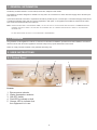
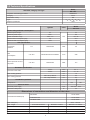
BRITONY SX 14 FF
INSTALLATION, SERVICING AND USER’S MANUAL
Fan Flued Instantaneous Multipoint Water Heater
IMPORTANT: THIS
APPLIANCE IS A DOMESTIC HOT WATER APPLIANCE AND IS INTENDED FOR DOMESTIC USE ONLY
Manufacturers N°
3675031
Country of destination
GB
IE
Model Type
Gas Council N°
Britony SX 14 FF
52 - 980 - 25
c
TABLE OF CONTENTS
1.
1.1
GENERAL INFORMATION
Guarantee
Page. 3
Page. 3
2.
2.1
2.2
2.3
2.4
2.5
USER INSTRUCTIONS
Control Panel
Initial Set-Up
Use
Maintenance
Useful Information
Page. 3
Page. 3
Page. 4
Page. 4
Page. 5
Page. 5
3.
3.1
3.2
3.3
3.4
3.5
3.6
3.7
3.8
INSTALLATION INSTRUCTIONS Page. 6
Description of Appliance
Page. 6
Technical Specifications
Page. 7
Operating Principle
Page. 8
Electrical Circuit Diagram
Page. 8
Appliance DImensions
Page. 9
Clearances
Page. 9
Reference Standards
Page. 10
Installing the Water Heater
Page. 11
4.
4.1
FITTING THE FLUE
Fitting the Coaxial Flue
(Ø 60/100 Horizontal)
Fitting the Coaxial Flue
(Ø 60/100 Vertical)
Fitting the Coaxial Flue
(Ø 80/125 Horizontal/Vertical)
Fitting the Twin Pipe (Ø 80/80)
Permissible Flue Lengths
Flue Types
Page. 15
Page. 16
Page. 18
Page. 18
5.
COMMISSIONING
Page. 19
6.
SERVICING INSTRUCTIONS
Page. 20
7.
7.1
7.1.1
7.2
REPLACEMENT OF PARTS
To Gain General Access
Removing the front panel
Access to the Combustion
Chamber
Removing the burner box
Removing the electrodes
Removing the burner
Removing the manifold
Removing the fan
Removing the air pressure
switch
Check the ∆P with the casing
closed
Acess to the Water Circuit
Drain down
Removing the heat exchanger
Removing the water valve
Access to the Control System
Removing the control box
Remvoing the electrical box
Removing the fuse
Removing the microswitch
Page. 20
Page. 20
Page. 20
4.2
4.3
4.4
4.5
4.6
7.2.1
7.2.2
7.2.3
7.2.4
7.2.5
7.2.6
7.2.7
7.3
7.3.1
7.3.2
7.3.3
7.4
7.4.1
7.4.2
7.4.3
7.4.4
7.5
Access to the Gas System
7.5.1 Removing the gas valve
Page. 13
Page. 13
Page. 14
Page. 21
Page. 21
Page. 21
Page. 22
Page. 22
Page. 23
Page. 23
Page. 23
Page. 24
Page. 24
Page. 24
Page. 25
Page. 26
Page. 26
Page. 26
Page. 27
Page. 27
2
Page. 28
Page. 28
8. FAULT FINDING CHART
Page. 29
9. SHORT SPARES LIST
Page. 31
1. GENERAL INFORMATION
The Britony SX Water Heater is a room sealed, fanned flue, mulitpoint water heater.
The appliance has been designed for domestic use only and to be connected to a mains cold water supply with a minimum pressure of 0.5 bar.
A permanent electrical connection is required and should be provided by use of a fused spur. The electrical supply should be via
a double pole isolating switch with 3mm contact separation in both poles. If the appliance is installed in a bathroom the fused
spur must be located externally to the bathroom.
NOTE: UNDER THE GAS SAFETY AND USE REGS 1984, IT IS THE LAW THAT ALL GAS APPLIANCES ARE INSTALLED BY A CORGI REGISTERED
ENGINEER. FAILURE TO INSTALL THE APPLIANCE IN ACCORDANCE WITH ALL CURRENT REGULATIONS WILL RESULT IN THE GUARANTEE
BECOMING VOID.
IN
HARD WATER AREAS THE USE OF A SCALE REDUCER IS RECOMMENDED.
1.1 Guarantee
The guarantee on this appliance is valid for 12 months from the date of installation, provided it has been installed in accordance
with this manual, with all current regulations and used solely for the purpose described in this manual.
Failure to comply with this will result in the guarantee becoming void.
2. USER INSTRUCTIONS
2.1 Control Panel
2
1
3
FIG. 1
LEGEND
1
2
3
4
5
Burner power selector
Water temperature selector
ON-OFF switch
Red LED to indicate a fault
Orange LED to indicate that
the equipment is in use
3
4
5
FIG. 2
2.2 Initial Set-Up
IMPORTANT:
The installing technician should explain to the user how the water heater works, the safety devices it includes and how
to use it.
Before turning the water heater on, it should be connected to the electrical mains via a double pole isolating switch
with 3mm contact separation in both poles.
• Make sure that gas is supplied to the water heater (valve on gas pipe open) and purge any air as necessary
• Make sure that the electrical supply is turned on.
2.3 Use
Obtaining hot water
To turn on the water heater press the ON-OFF button (3 Fig.2). The water heater will come on automatically whenever a hot
water tap is turned on.
Selecting the power rating
Turn the power selector (Fig. 3) to the desired power rating.
The MAX position represents full power: 100%.
The MIN position represents minimum power: 50%.
FIG. 3
Selecting the hot water temperature
Turn the water temperature selector (Fig. 4) to the desired water temperature.
The MAX position represents maximum temperature (minimum flow of water
through the appliance).
The MIN position represents minimum temperature (maximum flow of water
through the appliance).
FIG. 4
Resetting the water heater
In the event that the water heater locks out due to an ignition fault, the red LED
(B Fig. 5) will light.
Wait for at least three minutes before resetting the appliance by turning the
appliance off, waiting 10 seconds and turning the appliance back on again by
pressing button A, (Fig. 5).
Should the appliance continue to lock out, isolate the electrical supply to the
appliance at the fused spur and contact a local service agent.
A
B
FIG. 5
IMPORTANT:
This water heater is not controlled by a thermostat. The temperature of the water depends on the flow of water
and the power setting. Too much flow will reduce the temperature achieved. Adjust the flow at the tap to
achieve the desired temperature.
Note: It is suggested that both the power rating and the temperature are adjusted to the minimum values necessary to meet your
requirements. In this way energy is saved and the working life of the appliance is extended, reducing the build-up of lime scale in
the heat exchanger.
Stopping the water heater
When you turn off the hot-water taps, the water heater stops automatically.
In order to turn off the water heater, press the ON-OFF button (3 Fig. 2).
4
IMPORTANT:
In the event that there is a risk of the appliance freezing, close the cold water inlet valve and drain the water heater by opening a
hot water tap, see Section 2.5 Useful Information.
2.4 Maintenance
Note: Before carrying out any maintenance or repair work on the appliance, the water heater MUST be disconnected
from the electrical mains and the gas and water isolating valves MUST be closed.
CHAFFOTEAUX & MAURY recommends that the water heater be serviced by authorised personnel once a year.
The checks to be carried out are the following :
• The electrical installation is in good condition (the cable is not worn, there are no deposits of oil or grease on the
electrical connections, etc.);
• Check the appliance for leaks of gas and water;
• The combustion product ducts should be free from obstacles, correctly sealed and in good condition;
• The flow of gas and the gas pressure must be within the indicated values (See 3.2);
• Clean the burner and the heat exchanger.
Cleaning the burner
Remove the burner and clean the nozzles with a soft brush or with compressed air. Do not use chemical products (See 7.2.3);
Remove the ionisation and ignition spark devices in order to clean the tips (See 7.2.2);
Every 3 years the set of electrodes should be replaced.
Cleaning the heat exchanger
Clean the heat exchanger with hot water. If it is very dirty, leave the heat exchanger to soak in hot soapy water.
Refit the heat exchanger using new washers.
Cleaning the casing
Clean the casing with a damp cloth (DO
NOT USE ANY DETERGENTS).
Preventing lime scale build-up
If the appliance is installed in an area where the water is very hard, and over time it is observed that:
•
there is a decrease in the temperature of the hot water, or
•
there is a decrease in the flow of hot water
this means that lime scale has built up in the body of the heater.
In order to reduce this effect, we recommend that the desired water temperature is obtained by adjusting the power and gas controls and the temperature selector, and not by mixing the hot water from the heater with cold water.
In hard water areas a scale reducer is recommended to reduce the likelihood of scale formation in the heat exchanger.
Device for controlling the extraction of combustion products (air pressure switch).
Important : The user is not permitted to tamper with the device in any way. Under no circumstances is it to be disconnected,
modified or replaced by a different piece.
2.5 Useful Information
During cold spells, and if the appliance is situated in a place where it is subject to freezing conditions, the water circuit in the
appliance should be emptied in the following manner:
Turn off the cold-water tap supplying the water heater.
Turn on a hot-water tap which is fed by hot water from the water heater (this tap must be lower than the water heater itself).
Open the drain screw which can be found on the water valve (See 7.3.3).
5
3 INSTALLATION INSTRUCTIONS
3.1 Description of the Appliance
SX water heaters are sealed electronic water heaters, with electronic ignition and ionisation safety devices, they have a modulating burner and are connected to the mains water supply; they provide domestic hot water. Their self-contained combustion
chambers with fans for the intake of external air and the extraction of combustion products, allow them to operate totally independently from the room in which they are installed.
13
12
4
3
5
7
15
6
2
1
9
10
11
8
14
FIG. 5
Main components :
1. FRAME including the bar for suspending the water heater .
2. SEALED CHAMBER BASE, which, together with the casing, forms the combustion chamber
3. PRODUCTS EXTRACTION SET which includes the extractor body, fan, air pressure switch and coaxial outlet duct Ø 60-100
4. FAN for expelling the combustion gases to the outside through the tube Ø60 and to take in air from outside the chamber
5. HEATING BODY made of copper
6. BURNER made of stainless steel and with a blue flame which works with natural gas or Butane/Propane. Distributor fitted with
injectors that correspond to each type of gas
7. ELECTRODES for ignition and flame sensor which works by ionisation
8. GAS VALVE fitted with two safety valves, manual power rating selection, automatic power modulation according to the flow of
water and gradual progressive lighting of the burner.
9. WATER VALVE fitted with an automatic water flow regulator and with a manual temperature selector
10. ELECTRICAL POWER SUPPLY AND CONTROL: Supplies the water heater with 1.5 V from the mains supply at 220-230 V
a.c. Supplies the fan and, through the air pressure meter, controls the extraction of the combustion products.
11. ELECTRONIC CIRCUIT for igniting the flame and controlling it by means of ionisation.
12. AIR PRESSURE SWITCH which cuts off the intake of gas to the burner if waste products are not expelled correctly
13. COAXIAL OUTLET Ø 60-100
14. ELECTRICAL SUPPLY CABLE
15. HEAT EXCHANGER
6
3.2 Technical Specifications
Model
SX 14FF
Standard, Category and Type
Inspection certificate type number
0099BO814
II2H3P
Category
Destination country
GB
C12, C32, C42, C52, C82
Type
Degree of protection
IP44
Symbol
Model
Units
SX 14 FF
Power rating and heat consumption
Nominal power output
Pn
24
Minimum power output
Pmin.
8.9
Power modulation range
Pmin - Pn
KW
8.9 - 24
Nominal heat consumption (nett)
Qn
27.3
Minimum heat consumption (nett)
Qmin
12
Gas specification
Connection
pressure
2H
Natural G20
mbar
20
Gas
consumption
2 H / 2E+
Natural G20 Hi=9.45 kWh/m3
m3/h
2.88
Burner pressure at nominal power
2 H / 2E+
Natural G20
mbar
11.5
∆ 50°C
l/min
2.3 - 7
∆ 25°C
l/min
3.7 - 14
Hot-water specification
Flow rate of the water
Max. working pressure
Min. working pressure
bar
10
Max. Temp. selector
bar
0.5
Min. Temp. selector
bar
0.5
Combustion products
°C
Temperature
196
196
Electrical details
Electrical power supply
V/Hz
220-230V - 50Hz
Maximum intake power
W
55
Dimensions of connections and diameters of the tubes
Connections/Ø inside (mm)
Gas intake
1/2”/Ø 15mm
Cold Water Inlet
1/2”/Ø 15mm
Hot Water Outlet
1/2”/Ø 15mm
Flue outlet (mm)
Flue Length
Ø 60 - 100 mm
Ø 60/100 Horizontal
Maximum 3 metres
Minimum 0.37 metres
Ø 60/100 Vertical
Maximum 4 metres
Minimum 1.5 metres
Ø 80/125 Horizontal
Maximum 6 metres
Minimum 0.37 metres
Ø 80/125 Horizontal
Maximum 6 metres
Minimum 1.5 metres
7
3.3 Operating Principle
1.- Gas inlet
2.- Cold water inlet
3.- Gas filter
4.- Lower body
5.- Upper body
6.- Water regulator
7.- Test nipple
8.- Water filter
9.- Power selector
10.- Solenoid-valve
11.- Injector
12.- Distributor
13.- Main body
14.- Electrode set
15.- Power supply circuit and control of extraction
16.- Burner
17.- Heating body
18.- Fan assembly
19.- Air pressure switch
20.- Ignition box and ionisation safety unit
21.- Microswitch
22.- Distributor connector
23.- Combustion chamber
24.- Flue Connection Ø60-100
25.- Electrical supply cable
24
18
23
19
15
17
16
14
12
20
11
22
7
6
13
25
21
3
1
10
2
8
4
9
FIG. 6
5
3.4 Electrical Circuit Diagram
8
1
4
9
10
3
1.- ON/OFF Switch
2.- Supply connector
3.- Solenoid-valve
4.- Microswitch
5.- Power supply circuit and
control of extraction
6.- Air pressure switch
7.- Fan
8.- Ionisation electrode
9.- Confirmation electrode
10.- Spark electrode
11.- Red LED to indicate a fault
12.- Burner operation indicator
(LED)
2
Rele(Blanco)
G (Negro)
Presostato aire(Rojo)
Rele(Blanco)
Transparente
Transparente
Presostato aire(Rojo)
7
V-(Negro)
Rojo
V+(Rojo)
5
SW (Naranja)
SW (Naranja)
SV (Verde)
11
12
6
FIG. 7
8
3.5 Appliance Dimensions
Agujero
Hole ø 110
G
F
W
Tubo ø 100
Tube
E
X
L
B
O
H
Q
P
M
N
MODEL
14 litres
C
D
A
FIG. 8
Dimensions (mm)
Weight
(kg)
A
B
C
D
E
F
G
H
L
M
N
O
P
Q
W
X
16
330
595
230
247
60/100
34
122
230
513
50
61.5
592
75
14.5
138
143
3.6 Clearances
FIG. 9
9
3.7 Reference Standards
In the United Kingdom, the installation and initial start up of
the water heater must be by a CORGI Registered installer
in accordance with the installation standards curently in
effect, as well as with any and all local health and safety
standards i.e. CORGI.
Q
Q
I
Q
D,E
F
In the Republic of Ireland the installation and initial start up
of the appliance must be carried out by a Competent Person
in accordance with the current edition of I.S.813 “Domestic
Gas Installations” and the current Building Regulations, reference should also be made the the current ETCI rules for
electrical installation.
J
B
G
A
I
The installation of this appliance must be in accordance
with the relevant requirements of the Local Building
Regulations, the current I.E.E. Wiring Regulations, the bylaws of the local water authority. In Scotland, in accordance
with the Building Standards (Scotland) Regulation and
Health and Safety document No. 635, “Elelectricity at Work
Regulations 1989” and in the Republic of Ireland with the current edition of I.S. 813 and the Local Building Regulations
(IE).
N
C
L
M
N
H
H
M
K
FIG. 10
The minimum acceptable clearances are shown below:
- A Directly below an opening, window, etc
300 mm
300 mm
- B Above an opening, window, etc
- C Horizontally to an opening, window, etc
300 mm
- D Below gutters, soils pipes or drain pipes
75 mm
- E Below eaves
200 mm
200 mm
- F Below balconies or car port roof
- G From a vertical drain pipe or soil pipe
150 mm
- H From an internal or external corner
300 mm
- I Above ground roof or balcony level
300 mm
- J From a surface facing the terminal
600 mm
- K From a terminal facing the terminal
1200 mm
- L From an opening in the car port into the dwelling 1200 mm
- M Vertically from a terminal on the same wall 1500 mm
- N Horizontally from a terminal on the same wall 300 mm
- Q Fixed by flue terminal
C.O.S.H.H.
Materials used in the manufacture of this appliance are nonhazardous and no special precautions are required when
servicing.
Codes of Practice
Installation should also comply with the following British
Standards Codes of Practice:
BS 5546:1990
Installation of hot water supplies for
domestic purposes
BS 5440-1:2000 Flues
BS 5440-2:2000 Air Supply
BS 6891:1989
Installation of low pressure gas pipe up
to 28mm
IEE Wiring Regulations
BS 7671:2001
BS 5482:1994
Installation of L.P.G.
Installation of gas-fired hot water
BS 6798:1987
boilers of rated input not exceeding
60 kW
NOTE: THE
It may be necessary to protect the terminal with a guard.
Reference should be made to the Building Regulations for guidance.
and in the Republic of Ireland in accordance with the following
codes of practice:
I.S. 813
FLUE MUST NOT BE INSTALLED IN A PLACE LIKELY TO
CAUSE A NUISANCE.
Domestic Gas Installations
Flue
Detailed information on flue assembly can be found in Section
4 “Fitting the Flue”.
The appliance must be installed so that the flue terminal is
exposed to the free passage of external air at all times and
must not be installed in a place likely to cause nuisance. It
must not be allowed to discharge into another room or space
such as an outhouse or closed lean-to.
The terminal should be located with due regard for the damage or discolouration that might occur to buildings in the vicinity and consideration must also be given to adjacent boundaries.
In cold or humid weather, water vapour may condense on
leaving the flue terminal. The effect of such “pluming” must be
considered.
10
3.8 Installing the Water Heater
The appliance must be provided with a means of isolation. If
installed in a bathroom, the means of isolation must be external
to the bathroom or a double pole cord switch fitted.
The following elements are supplied with the heater :
1x
1x
1x
1x
1x
Cold water inlet pipe
Cold water inlet tap
Flexible hot-water outlet tube
Twin flue air inlet adaptor
Gas inlet tap
2x
2x
1x
1x
Plastic wall plugs
Screw hooks
Gas inlet pipe
Restrictor
Assorted washers
Acceptable methods of connection are:
• A switched double pole fused spur with 3mm contact
separation on all poles.
The dimensions for installing the appliance are detailed in
Sections 3.5 and 3.6 (page 9).
• A double pole switch where the supply must be suitably
fused 3A.
Siting the Appliance
• An unswitched socket outlet complying with BS 1363.
The location chosen for the appliance must permit the provision
of a satisfactory flue termination (see Fig. 10, Section 3.7). The
location must also permit adequate space for servicing and air
circulation around the appliance (see Fig. 9, Section 3.6).
The appliance may be installed in any room or internal space,
although particular attention is drawn to the current requirements of the current edition of BS7671, in Scotland, the electrical provisions of the Building Standards applicable in Scotland,
and in Ireland in line with the electrical provisions of I.S. 813,
with respect to the installation of a heater in a room or internal
space containing a bath or shower.
A three core cable should be used and a heat resistant cable of
0.75 mm2 (24 x 0.2 mm) is considered suitable.
Removing the Outer Case
Remove the gas and water control knobs;
Loosen the screw behind the control knob that secures the outer
case;
Release the two locks on the top of the casing and remove the
case (See also Section 7.1.1, page 20).
Where a room sealed appliance is installed in a room containing a bath or shower, any electrical switch or appliance control
using main electricity should be situated so that it cannot be
touched by a person using the bath or shower.
Wall Mounting
Where the installation of the appliance will be in an unusual
location, special procedures may be necessary, the current edition of BS 5546 should be consulted.
Connecting the Heater to the Water and Gas Supplies
Fix the two screw-in hooks to the wall and hang the water heater
on them.
In the event that the appliance is to be installed in a timber
framed building, it should be fitted in accordance with the British
Gas Document ‘Guide for Gas Installations in Timber
Framed Housing’ reference DM2. If in doubt, advice must be
sought from British Gas.
Before connecting up the appliance it is necessary to thoroughly flush and purge the water and gas pipes in order to remove
filings or other waste from them;
Connect the water heater using the corresponding washers and
connectors which are supplied in the bag of accessories;
Place the casing back on and secure it in place;
Replace the gas knob and the temperature selector knob;
Gas Supply
Sealing the Water Circuit
An adequate sized gas meter must be connected to the service
pipe. Where necessary the local gas supplier will arrange for
the existing meter to be checked or for a suitable meter to be fitted.
Installation pipes should be fitted in accordance with BS 6891.
Pipework from the meter must be of adequate size. Pipes of a
smaller size than the gas connection must not be used.
The complete installation must be tested for gas soundness and
purged in accordance with the current edition of BS 6891.
Open the water inlet tap into the appliance by turning the water
inlet tap on the heater fully on. Bleed any air from the water
pipes by opening all the taps: hot and cold. Then turn off all the
taps and check for watertightness.
Air Supply
Connecting the Water Heater to the Electrical Mains
The appliance does not require any purpose provided ventilation.
The water heater is fitted with an electrical supply cable for a
220-230V~50Hz mains supply. It is to be connected to a singlephase power supply with an earth.
In order to protect the heater it is necessary to have a bipolar
switch with a minimum opening distance of 3 mm.
Sealing the Gas Circuit
IMPORTANT!
Test for soundness in accordance with current regulations.
Electrical Supply
The appliance must be earthed.
IMPORTANT : Whenever carrying out an operation on the
electrical installation of the heater, make sure that the
heater is disconnected from the mains power supply
The new power cable is to have the same specifications as the
one originally installed in the heater.
The means to isolate the power supply should be easily accessible.
The installation must be undertaken by a competent electrician
and should be in accordance with the current edition of BS
7671.
Particular attention should be paid to cross bonding.
11
3.8 Installing the Water Heater
Purging the Gas Supply
Once all the above checks are complete, it will be necessary to
purge the gas supply of air. Do not under any circumstances
attempt to purge the gas pipe of air by continually pressing the
On/Off button to reset. If it is necessary to do this, you must
wait at least three minutes between each press of the On/Off
button.
Completion
Once installation is complete, commission the appliance as
instucted in Section 5, page 19).
Instruct the end user on the following:
•
How to switch off the appliance quickly and indicate the
position of the electrical supply isolator.
•
Explain to the end user that if the appliance is not to be
used for long periods that it is advisable to drain the
appliance to prevent damage in the event of it freezing.
•
Advise the end user that to ensure safe and effective
operation, the appliance must be serviced once a year by a
CORGI registered gas engineer.
•
Finally, leave these instructions with the end user.
12
4. FITTING THE FLUE
The water heater must only be installed with a flue supplied by the manufacturer.
These kits are supplied separately to the appliance in order to respond to different installation solutions. For more information
with regard to the inlet/outlet accessories consult the flue brochure and the following instructions. The water heater is supplied
ready for connection to a concentric gas intake and exhaust duct system.
WARNING!!
The exhaust gas ducts should not be in contact with or close to inflammable material and should not pass through building structures or walls made
of inflammable material.
When replacing an old appliance, the flue must be changed.
IMPORTANT!!
Ensure that the flue is not blocked.
Ensure that the exhaust gas ducts do not
have leaks
Ø 60/100 mm
Fig. 11
4.1 Fitting the Coaxial Flue (Ø 60/100 Horizontal)
CONTENTS:
1X SILICONE O-RING (60mm)
1X ELBOW (90 )
2X WALL SEALS (INTERNAL & EXTERNAL)
1X FLUE PIPE INCLUDING TERMINAL (1 METRE - 60/100)
2X FLUE CLAMPS
4X SCREWS
2x Seals
Once the water heater has been positioned on the wall, insert
the elbow into the socket and rotate to the required position.
NOTE: It is possible to rotate the elbow 360o on its vertical axis.
O
If necessary, fit the restrictor ring (see Fig. 12 and Table on
Page 18).
Coaxial
Using the flue clamp, seals and screws supplied (Figs. 11 &
13) secure the elbow to the boiler.
The 1 metre horizontal flue kit (3318000) supplied is suitable
for an exact X dimension of 823 mm.
Fig 12
WARNING!!
Consult the table on Page 18, to see if a restrictor is
required for the type of flue system being used. Should it
be necessary to fit the restrictor, it must be fitted as shown
in Fig. 12.
Measure the distance from the face of the external wall to the
face of the flue elbow (X - Fig 11), subtract 48 mm from this
measurement, you now have the total length of flue required
(including the terminal), this figure must now be subtracted
from 907mm, you now have the total amount to be cut from the
plain end of the flue.
Cut the flue to the required length ensuring that the distance
between the inner and the outer flue is maintained (Fig 14).
13
4.1 Fitting the Coaxial Flue (Ø 60/100 Horizontal) Continued/......
Clamp
e.g.
X = 508mm - 48mm = 460mm
823 - 460 = 363mm (Length to be cut from the plain
end of the flue).
Ensure that the inner flue is 23mm longer than the outer
flue. See Fig. 14.
Once cut to the required length, ensure that the flue is
free from burrs and reassemble the flue. If fitting the flue
from inside of the building attach the grey outer wall seal
to the flue terminal and push the flue through the hole,
once the wall seal has passed through the hole, pull the
flue back until the seal is flush with the wall.
Alternatively, the flue can be installed from outside of the
building, the grey outer seal being fitted last.
Should the flue require extending, the flue connections are push fit, however, one flue bracket should
be used to secure each metre of flue.
Screws
Seal
23 mm
FIG. 13
L
L
23 mm
1
1
2
2
m
m
23
FIG. 14
4.2 Fitting the Coaxial Flue (Ø 60/100 Vertical)
NOTE: SEE
PAGE
18
FOR MAXIMUM AND MINIMUM FLUE RUNS.
CONTENTS:
1X SILICONE O-RING (60mm)
1X CONICAL ADAPTOR (60/100mm)
1X VERTICAL FLUE KIT (80/125mm)
3X SCREWS
The vertical flue kit is supplied with a specially designed
weather proof terminal fitted, it can be used either with
a flat roof or a pitched roof.
The Vertical flue kits useable lengths with the pitched
roof flashings are indicated in Fig. 15.
Before proceeding to fit the flue, ensure that the maximum flue length has not been exceeded (See the tables
on Page 18) and that all elbows and bends have been
taken into consideration, the maximum flue length is 4
metres, for each additional 90o elbow 1 metre must be
subtracted from the total flue length, and for each 45o
0.5 metres must be subtracted from the total flue length
(the height of the vertical adaptor and a 45o bend
can be seen in Fig. 16).
Fig. 15
Mark the position of the flue hole in the ceiling and/or
roof (see Fig. 15 for distance from wall to the centre of
the flue).
Cut a 120mm diameter hole through the ceiling and/or
roof and fit the flashing plate to the roof.
14
4.2 Fitting the Coaxial Flue (Ø 60/100 Vertical) Continued/......
DO NOT cut the vertical flue kit.
To connect the vertical flue kit directly to the boiler, place the
vertical starter kit (Part No. 3318008) (see Fig. 15) onto the
exhaust manifold and secure with the clamp, fit the
Ø125/100 adaptor onto the vertical starter kit (note: there is
no need to use a clamp to secure this as it is a push fit connection), the vertical flue kit must then be inserted through
the roof flashing from the outside, this will ensure that the
correct clearance above the roof is provided as the terminal
is a fixed height.
Should extensions be required, they are available in 1 metre
(Part No. 3318005), 500mm (Part No. 3318006) and
250mm lengths (Part No. 3318007), they must be connected directly to the vertical starter kit before connecting the
adaptor to allow the vertical flue kit to be fitted. In the event
that extension pieces need to be shortened, they must only
be cut at the male end and it must be ensured that the distance between the inner and outer flue is maintained (Fig.
14).
When utilising the vertical flue system, action must be taken
to ensure that the flue is supported adequately to prevent
the weight being transferred to the appliance flue connection
by using 1 flue bracket per extension.
Fig. 16
When the flue passes through a ceiling or wooden floor,
there must be an air gap of 25mm between any part of the
flue system and any combustible material. The use of a ceiling plate will facilitate this. Also when the flue passes from
one room to another a fire stop must be fitted to prevent the
passage of smoke or fire, irrespective of the structural material through which the flue passes.
4.3 Fitting the Coaxial Flue (Ø 80/125 Horizontal / Vertical)
NOTE: SEE
PAGE
18
FOR MAXIMUM AND MINIMUM FLUE RUNS.
Once the boiler has been positioned on the wall, for horizontal flue runs, insert the Ø60/100 elbow onto the boiler, and connect the elbow to the Ø80/125 adaptor, for
vertical flue runs it is necessary to insert the Ø80/125
adaptor (FIG. 17) (not supplied with flue kit - Part No
3318040) into the boiler flue socket.
Push the adaptor onto the boilers flue connection,
grease the seals then add extensions or elbows as
required, secure the adaptor, using the clamp and
screws provided.
To fit extensions or elbows it is first necessary to ensure
that the lip seal is fitted correctly into the inner flue, once
verified, it is simply necessary to push them together, no
clamps are necessary to secure the flue components.
FIG. 17
Before proceeding to fit the flue, ensure that the maximum flue length has not been exceeded (See the tables
on Page 18) and that all elbows and bends have been
taken into consideration, the maximum flue length is 6
metres, for each additional 90o elbow 1 metre must be
subtracted from the total flue length, and for each 45o
0.5 metres must be subtracted from the total flue length
(the height of the vertical adaptor and a 45o bend
can be seen in Fig. 18 and a 90o bend in Fig. 19).
NOTE: DO NOT
15
CUT THE VERTICAL FLUE KIT.
4.3 Fitting the Coaxial Flue (Ø 60/100 Vertical) Continued/.......
FIG. 18
FIG. 19
4.4 Fitting the Twin Pipe (Ø 80/80)
NOTE: SEE
PAGE
18
FOR MAXIMUM AND MINIMUM FLUE RUNS.
Where it is not possible to terminate the flue within the distance permitted for coaxial flues, the twin flue pipe can be
used by fitting a special adaptor to the flue connector and
using the aperture for the air intake located on top of the
combustion chamber.
WARNING!!
Consult the table on Page 18, to see if a restrictor
is required for the type of flue system being used.
Should it be necessary to fit the restrictor, it must
be fitted as illustrated in Fig. 20.
Always ensure that the flue is adequately supported, avoiding low points. (MTS supply suitable clamps as Part No.
3318015).
To utilise the air intake it is necessary to:
1) Take the air intake cover off
2) Assemble the flange on the header supplied with the
appliance
3) Insert the restrictor if necessary, between the tube and
the elbow
4) Insert the header on the tube or the elbow up until the
lower stop (you do not have to use a washer).
5) Insert the elbow/header in the boiler air intake hole and
fasten it with screws.
Fig. 20
The twin flue pipes can be fitted with or without additional
elbows and need no clamps, simply ensure that the red oring is inserted in the female end of the flue pipe and push
the extension piece fully into the previous section of flue pipe
or elbow, check that the o-ring is not dislodged when assembling the flue.
Twin flue
Twin pipe can also be converted back to Coaxial flue to
enable vertical termination with a coaxial kit by using the
pipe bridge (Twin - Coaxial Adaptor - Part No. 3318033).
When running the twin flue pipe vertically.
16
4.4 Fitting the Twin Pipe (Ø 80/80) Continued/.......
122
200
230 MIN *
132
123,5
When siting the twin flue pipe, the air intake and exhaust terminals must terminate on the same wall, the centres of the
terminals must be a minimum of 280 mm apart and the air
intake must not be sited above the exhaust terminal (refer to
Fig. 23). The air intake pipe can be run horizontally, however, the terminal and the final 1 metre of flue must be installed
with a fall away from the boiler to avoid rain ingress.
It is also strongly recommended that the air intake pipe run
be constructed of insulated pipe to prevent condense forming on the outside of the tube.
Fig. 21
The maximum permissible flue length for twin flue is
dependent on the type of run used.
For flue runs with the intake and exhaust pipes under the
same atmospheric conditions (TYPE 4) the maximum length
is 10 metres (5 metres for the air intake and 5 metres for the
exhaust), for runs with the terminals under different atmospheric conditions (TYPE 5) the exhaust terminal must extend
0.5 metres above the ridge of the roof (this is not obligatory
if the exhaust and air intake pipes are located on the same
side of the building). For TYPE 5 also, the maximum permissible combined length is 10 metres (5 metres for the air
intake and 5 metres for the exhaust).
In the event that twin flue pipes are used, and the water
heater has a side clearance of less than 60mm from the
wall, it is necessary to cut a larger diameter hole for the
flue pipe, this should be ø10 cm, this will then allow for
easier assembly of the air intake elbow and the tube
outside the wall (see Fig. 22).
ø 100
The maximum length is reached by combining the total
lengths of both the air intake and exhaust pipes. Therefore
a maximum length of 10 metres for example, will allow a flue
run of 5 metres for the air intake
and 5 metres for the
o
exhaust pipes, also for each 90 elbow 2.2 metres must be
subtracted from the total length and for each 45o elbow 1.4
metres must be subtracted from the total flue length.
Some of the acceptable flue configurations are detailed on
page 18.
60 mm
For further information relating to flue runs not illustrated,
please contact the Technical Department on 0870 241 8180.
FIG. 22
AIR INTAKE MUST NOT BE
FITTED ABOVE THE EXHAUST
AIR INTAKE
EXHAUST
AIR INTAKE
FIG. 23
17
4.5 Permissible Flue Lengths
SX 14 FF
Exhaust Type
Type 1
Coaxial
Systems
ø 60/100
Type 2
Type 3
Type 1
Coaxial
Systems
ø 80/125
SX 14 FF
Twin Pipe
Systems
ø 80/80
Type 2
Use the
ø 85 mm
Restrictor
Between
0.3 m / 1 m
Between
0 m / 1.5 m
Between
0 m / 1.5 m
Between
0.3 m - 2 m
Between
0m-2m
Do not use the Maximum Flue Reduction for Reduction for
Restrictor
Length
90o Bend
45o Bend
1m-3m
3m
1m
0.5 m
1.5 m - 4 m
4m
1m
0.5 m
1.5 m - 4 m
4m
1m
0.5 m
2m-6m
6m
1m
0.5 m
2m-6m
6m
1m
0.5 m
2m-6m
6m
1m
0.5 m
Type 3
Between
0m-2m
Exhaust Type
Use the
ø ?? mm
Restrictor
Type 4
Between
0m-3m
Between
3 m - 10 m
10 m
1.4 m
2m
Type 5
Between
0m-3m
Between
3 m - 10 m
10 m
1.4 m
2m
Do not use
Maximum
the Restrictor Flue Length
Reduction for Reduction for
90o Bend
45o Bend
The Ø 85 diaphragm is included in the accessories kit with the SX 14FF model.
4.6 Flue Types
TYPE 1
TYPE 2
TYPE 5
TYPE 4
NOTE: DRAWINGS
ARE INDICATIVE OF FLUEING OPTIONS ONLY.
18
TYPE 3
Fig. 24
5. Comissioning
Once the water heater installation has been completed, it is necessary to commision the appliance as follows:
Gas supply installation
Inspect the entire installation including the meter, test for soundness and purge, as described in BS 6891.
Checking electricity supply
Carry out preliminary checks for earth continuity, polarity, resistance to earth and short circuit.
Leave the appliance with the front cover fitted and the mains electrical supply isolated.
Fig. 25
Lighting the boiler
Ensure that the gas and water service valves below the appliance
are open;
Ensure that the gas supply is properly purged as BS 6891;
Open a hot water tap and ensure that all air is purged from the
appliance and the pipes;
Switch on the mains electrical supply, and turn the appliance on
at the On/Off switch;
Turn on a hot water tap;
The appliance will attempt to ignite, should this fail due to air in
the gas pipe, the appliance will lock-out, it will be neccessary to
reset the appliance as explained in Section 2.3 (page 4).
Fig. 26
Setting the gas pressures
Connect a manometer to the test nipple on the gas section (1,
Fig. 25) and check for adequate standing pressure.
Turn on the hot water tap nearest to the water heater and ensure
that the working pressure is that shown in Table A.
Once the working pressure has been established, check that the
burner pressure is that indicated in Table A.
To check the burner pressure, it is necessary to connect a
manometer to the test nipple (2. Fig. 26), should the burner pressure require adjusting, use the screw (3, Fig. 27) to adjust, turn
clockwise to increase the pressure and anti-clockwise to
decrease the pressure.
NOTE: THIS
APPLIANCE IS NOT SUITABLE FOR CONVERTING FROM ONE
GAS GROUP TO ANOTHER, IT IS RECOMMENDED THAT THE CORRECT WATER
HEATER BE ORDERED TO MATCH THE TYPE OF GAS BEING USED.
Fig. 27
TABLE A
Working Pressure
Natural
20 mbar
Burner Pressure
Natural
12.7 mbar
19
6. SERVICING INSTRUCTIONS
A
To ensure efficient safe operation, it is recommended that
the water heater is serviced annually by a competent person.
Before starting any servicing work, ensure both the gas
and electrical supplies to the water heater are isolated
and the water heater is cool.
Before and after servicing, a combustion analysis should be
made via the flue sampling point.
After servicing, preliminary electrical system checks must
be carried out to ensure electrical safety (i.e. polarity, earth
continuity, resistance to earth and short circuit).
FIG. 28
7. REPLACEMENT OF PARTS
FIG. 29
The life of individual components vary and they will need
servicing or replacing as and when faults develop.
The fault finding sequence chart in Section 8 will help to
locate which component is the cause of any malfunction,
and instructions for removal, inspection and replacement of
the individual parts are given in the following pages.
7.1 To Gain General Access
All testing and maintenance operations on the water heater
require the removal of the casing.
7.1.1 Removing the front panel :
1. Unlock the two clamps locking A (see Figs. 28);
2. Remove the control knobs and the screw below (see
Fig. 29).
3. Remove the front panel from the rest of the casing
(see Fig. 30).
FIG. 30
20
7.2 Access to the Combustion Chamber
7.2.1 Removing the burner box
1. Carry out step 7.1.1;
2. Remove the two clips, one on either side of the burner box (Fig. 31 & 32);
4. Pull the burner box towards you
(Fig. 33).
5. Reassemble in reverse order.
B
B
FIG. 32
FIG. 33
3. Remove the screw C from the
manifold (Fig. 35);
4. Pull the electrodes towards you
(Fig. 36).
5. Reassemble in reverse order.
FIG. 31
7.2.2 Removing the electrodes
1. Carry out step 7.1.1 and 7.2.1;
2. Disconnect the electrodes wire
(Fig. 34);
C
FIG. 34
FIG. 35
21
FIG. 36
7.2.3 Removing the burner
1. Carry out step 7.1.1 and 7.2.1;
2. Disconnect the electrodes wire
(Fig. 37);
3. Remove the 2 screws D from the
combustion chamber (Fig. 38);
4. Remove the 2 screws E between
the elbow and the gas valve
(Fig. 39);
D
E
FIG. 37
FIG. 38
FIG. 39
5. Remove the 2 screws F fixing
the burner to the combustion
chamber (Fig. 40).
6. Pull the burner towards you (Fig.
41);
7. Remove the screws G, H, I to
free the burner from the gas
elbow, the electrodes and the
manifold (Fig. 42);
8. Reassemble in reverse order
G
H
I
F
FIG. 40
FIG. 42
FIG. 41
7.2.4 Removing the manifold
1. Carry out step 7.1.1 and 7.2.1;
2. Remove the burner as in step 7.2.3;
3. Remove the 2 screws I between the burner and the manifold (Fig. 43);
4. Remove the 3 screws G & H to free the
manifold from the gas elbow and the electrodes (Fig. 44);
5. Reassemble in reverse order.
G
G
H
H
I
FIG. 44
FIG. 43
22
7.2.5 Removing the fan
1. Carry out step 7.1.1;
2. Remove the fan wires (Fig. 45);
3. Remove air pressure switch connections K (noting position Fig. 43);
4. Remove the screws J & L to free the
fan (Fig. 45, 46, 47 & 48);
K
L
K
4. Pull the fan towards you (Fig.
49);
5. Reassemble in reverse order.
J
FIG. 47
FIG. 46
L
L
FIG. 49
FIG. 48
FIG. 45
7.2.6 Removing the air pressure switch
1. Carry out step 7.1.1;
2. Remove the wires M and air
pressure switch pipes N noting
position (Fig. 50);
M
3. Remove the two screws O (Fig.
51 & 52);
4. Reassemble in reverse order
N
O
FIG. 52
FIG. 50
FIG. 51
7.2.7 Check the ∆P with casing closed
1. Remove the protection cap at the
top of the appliance (Fig. 53);
2. Connect the manometer and
measure the ∆P (Fig. 54);
3. Ensure that the cap is replaced
after measurement.
FIG. 53
FIG. 54
23
7.3 Access to the Water Circuit
Important! Before any component is removed, the water heater must be drained of all water.
7.3.1 Drain down
1.
2.
3.
4.
5.
Carry out step 7.1.1;
Turn OFF the cold water inlet tap on the appliance;
Place a container under screw P (Fig. 55) to catch any water;
Remove the screw P on the water valve (Fig. 55 & 56);
Turn ON the hot water outlet tap.
P
FIG. 55
FIG. 56
7.3.2 Removing the heat exchanger
1. Carry out steps 7.1.1 & 7.3.1;
2. Free the air pressure switch wires
from the heat exchanger by
removing the clip (Fig. 57);
3. Unscrew the nut on the
exchanger hot water outlet (Fig.
58);
4. Unscrew the nut on the
exchanger water inlet (Fig. 59);
FIG. 57
FIG. 58
FIG. 59
5. Remove the two clips between the heat exchanger and the top of the
combustion chamber (Fig. 60 & 61);
6. Pull the exchanger towards you
(Fig. 62);
7. Reassemble in reverse order.
FIG. 60
FIG. 61
24
FIG. 62
7.3.3 Removing the water valve
1. Carry out step 7.1.1;
2. Drain the water heater as in step 7.3.1 by removing the screw P (Fig. 63) after turning OFF the
water inlet tap and turning ON the water outlet
tap;
3. Remove the nut between the water valve and the
heat exchanger (Fig. 64);
P
FIG. 64
FIG. 63
4. Remove the two screws Q (Fig 65 & 66);
5. Pull the water valve toward the right (Fig. 67);
6. Reassemble in reverse order.
Q
Q
FIG. 65
FIG. 66
25
FIG. 67
7.4 Access to the Control System
7.4.1 Removing the control box
1. Carry out step 7.1.1;
2. Disconnect the electrodes wires
(Fig. 68);
3. Remove the gas valve wires
(Fig. 69);
4. Remove the screws R1 & R2
and pull the control box towards
you (Fig. 70)
5. Reassemble in reverse order.
R1
R2
FIG. 68
FIG. 69
Fig. 70
3. Remove connections on the
control box (Fig. 73);
4. Remove the screw R1 to free the
earth connections (Fig. 74);
7.4.2 Removing the electrical box
1. Carry out step 7.1.1;
2. Disconnect the fan and air pressure switch wires (Fig. 71 & 72);
R1
FIG. 71
FIG. 72
FIG. 73
5. Remove the two screws R3 below the appliance and pull the control box
towards you (Fig. 75 & 76)
6. Reassemble in reverse order.
R3
R3
FIG. 75
FIG. 76
26
FIG. 74
7.4.3 Removing the fuse
1. Carry out step 7.1.1;
2. Remove the five screws S on
the electrical box (Fig. 77);
3. Remove electrical box cover
(Fig. 78);
4. Remove the fuse (Fig. 79);
5. Reassemble in reverse order.
S
FIG. 77
FIG. 78
FIG. 79
3. Remove the two screws T (Fig.
81);
4. Pull the microswitch down (Fig.
82);
5. Reassemble in reverse order.
7.4.4 Removing the microswitch
1. Carry out step 7.1.1;
2. Disconnect the microswitch (Fig.
80);
T
FIG. 80
FIG. 81
27
FIG. 82
7.5 Access to the Gas System
7.5.1 Removing the gas valve
1. Carry out steps 7.1.1 & 7.3.1;
2. Remove the microswitch as in
step 7.4.4 (Fig. 83);
3. Disconnect the gas valve (Fig.
84);
FIG. 85
FIG. 84
FIG. 83
5. Remove the 2 screws U between
the electrical box and the gas
valve (Fig. 86);
4. Remove the water valve as in
step 7.3.3 (Fig. 85);
6. Remove the 2 screws E between
the elbow and the gas valve (Fig.
87);
7. Remove the 2 screws V securing
the gas valve on the chassis
(Fig. 88);
U
V
E
FIG. 87
FIG. 86
28
FIG. 88
8. FAULT FINDING CHART
PRELIMARY CHECKS
MAKE SURE THAT:
1 - The mains water supply is turned on
2 - The gas is turned on
3 - The electrical supply is turned on
PRESS THE ON/OFF BUTTON
DRAW OF WATER > 2.3 L/min
HAS THE
MICROSWITCH
CLOSED?
NO
POWER TO
MICROSWITCH?
YES
NO
1 - Check/replace connection cable
2 - Check/replace water group diaphragm
3 - Check/replace the printed circuit board
YES
1 - Replace microswitch
HAS THE FAN
STARTED TO RUN?
NO
MOMENTARY
POWER TO
FAN ?
YES
NO
1 - Check/replace connection cable
2 - Check/replace control box
3 - Check/replace electrical box
YES
1 - Replace fan
HAS THE
IGNITION SEQUENCE
BEGUN ?
NO
YES
IS FAN
RUNNING
CONTINUOUSLY?
YES
IS SPARK
GENERATION
NORMAL ?
1 - Check air pressure switch
2 - Check venturi & pipes
3 - Check fan efficiency
NO
1 - Check ignition electrode cable
2 - Check/replace ignition electrode
3 - Check/replace control box
4 - Check/replace electrical box
NO
1 - Check power supply of gas valve
2 - Check efficiency of gas valve
3 - Replace gas valve
4 - Check/replace control box
5 - Check/replace electrical box
YES
IS THE BURNER
ALIGHT ?
YES
HAS THE
BOILER SAFETY
SHUTDOWN BEEN
ACTIVATED ?
1 - Check if flame strikes detection electrode
2 - Check soft-light gas pressure
3 - Check/replace detection electrode
4 - Check/replace control box
5 - Check/replace electrical box
YES
NO
A
FC P010a
29
A
IS
THERE STILL
A PROBLEM?
FAULTS
YES
POSSIBLE CAUSES
1 Drawing D.H.W:
- check gas pressures
- check water flow rate
- check heat exchanger
insufficient hot water
temperature
NO
2 Drawing D.H.W:
noisy operation
- heat exchanger faulty or lime-scale deposits
- low heating system water pressure
- check gas pressures
Repeated shutdowns
- faulty detection electrodes
- check gas settings
- check flame detection electric circuit
When cold water tap turned off, the water
heater ignites
- drop in pressure in the water mains, with
consequent water hammer
NORMAL
OPERATION
3
4
FC P011
30
9. SHORT SPARES LIST
SHORT LIST
702
103
206
102
216
901
607
601
632
636
616
631
631
633
Description
G.C N° Manf. Pt. N°
Type
FF
100
102
103
200
206
FRONT CASE
KNOB
FACIA
FAN ASSEMBLY
FAN ASSY
FAN ASSY
216
AIR PRESSURE SWITCH
AIR PRESSURE SWITCH
600
601
61400288
61400289
61400261
61401861
61400262
61401809
GAS SECTION
GAS SECTION NAT ASSY
GAS SECTION NAT ASSY
607
616
631
632
633
634
635
636
IGNITION ELECTRODE
700
702
WATER SECTION ASSY
900
901
JIG PLATE & PIPE FITTING
MICRO SWITCH BOX
CABLE
CABLE
ELECTRICAL BOX
CONTROL BOX
FUSE 250V 0.5A - TEMPORIZED
CABLE
DIAPHRAGM
CONNECTION KIT
61400270
61401802
61400271
61400272
61400274
61400298
61400276
61400275
61400290
61400299
61400278
61401808
NAT
NAT
..
.
..
..
..
..
..
.
.
.
.
.
.
.
.
.
.
.
.
..
..
..
31
Manf. date
from
to
03/05
Key N°
FL
U
EN
DO
14
635 634
AND
CONDITIONS
Please read these terms and conditions which are in
addition to any terms and conditions detailed in this book
or any registration card supplied with your appliance.
A charge will be made to the owner of the appliance if:
∑
∑
∑
∑
The reason for any service visit is as a direct result
of a failure to install the appliance in accordance
with the manufacturer’s instructions.
Your installer does not complete the necessary
commissioning process and procedure as detailed in
the Installation and Operating Instructions.
Your appliance is not serviced on or before the 12
month anniversary of installation - this only applies to
appliances with a 2 and 5 year guarantee.
Our service engineer calls as requested and the
failure is a non-manufacturing defect.
Failure to pay an invoice for any such occurence will be
assumed by MTS that you accept that your appliance has
not been installed correctly and understand that any manufacturer’s guarantee has been withdrawn.
OF
GUARANTEE
On the 12 month anniversary of the appliance installation,
you must have it serviced to continue any guarantee
offered into the following year. Failure to do so will invalidate your guarantee and should an MTS engineer be
required to attend and no proof of service documentation
is made available, then MTS will charge.
As part of the commissioning process, it is a legal requirement to register all installations or replacements with
CORGI. Upon registration a “Certification Number” will be
issued followed by a “Declaration of Safety” Certificate.
MTS (GB) Ltd cannot be called upon to carry out any
work under the manufacturer’s guarantee without proof of
registration. The registration number must be quoted
when requesting a service visit, and the “Declaration of
Safety” Certficate subsequently shown to the service
engineer.
If the certificate is not made available, the engineer will
not work on the appliance and a wasted call charge will
be made.
If you have a problem with commissioning on installation, please contact our
Technical Department on 0870 241 8180
Manufacturer: Chaffoteaux & Maury - France
Commercial subsidiary: MTS (GB) Limited, MTS Building, Hughenden Avenue, High Wycombe, Bucks HP13 5FT
1315229c - 03/2005
TERMS