1
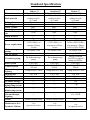
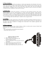
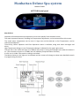
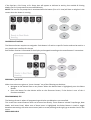
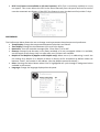
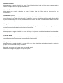
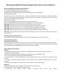
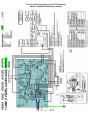
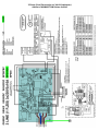
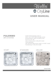
USER MANUAL MANHATTAN SPA SYSTEM - 1x 3HP or 2x2 HP Hydromassage pump INDOOR and OUTDOOR version New GS100/VL260 control system 20 or 36 jets Chromotherapy lamp with 55 LEDs Version: 01.2014 www.wellis.eu Standard Specification Dimensions Shell material Sitting places Reclining places Water volume Net weight Total number of jets Water diverter Air diverter Power requirement Hydromassage pumps Hot air blower Circulation pump Filter system Control system Indoor □ 2130 x 1600 x 750 mm PU reinforced, outdoor acrylic (6,3 mm) 2 persons 1 person 660 l 250 kg Standard □ 2130 x 1600 x 750 mm PU reinforced, outdoor acrylic (6,3 mm) 2 persons 1 person 660 l 260kg Deluxe □ 2130 x 1600 x 750mm PU reinforced, outdoor acrylic (6,3 mm) 2 persons 1 person 660 l 290 kg 20 pc. 20pc. 36pc. ----3pc 3pc optimum 1 Phase 1x25A optimum 1 Phase 1x25A (230V/50Hz); or (230V/50Hz); or minimum 1 Phase minimu1 Phase 1x16A 1x16A --3pc optimum 3 Phase, 3x16A (400V/50Hz); or minimum 1 Phase, 1x25A (230V/50Hz) 1x 2speed, 3 HP 1x 2speed, 3HP 2x 1speed, 2HP no no By hydromassage pump By hydromassage pump 1 set (1pc.) BALBOA GS100 / VL260 1 set (1pc.) BALBOA GS100/ VL260 1pcs 300W Energy-efficient LAING circulation pump (0,1kW/h) 1 set (1pc.) BALBOA BP2100 / TP800 1 lamp with 55 LEDs 1 lamp with 55 LEDs 1 lamp with 55 LEDs 1 pc 3kW --3 pc --- 1 pc 3 kW 1 pc 3 pc --- 1 pc 3kW 1 pc 3 pc 1 pc --- --- 1 pc --- --- --- Chromotherapy lighting Heating unit 1,5” drain connect Headrest Aromatic therapy Ozone generator disinfecting system UV-C lamp disinfecting system Exklusive Chromotherapie Lighting Frame --- --- 12 x 1 LED surface-treated wood surface-treated wood WPC Maintenance-free Synthetic Cabinet 1 set (just one,fix color) 1 set (in optional colors) 1 set (in optional colors) WARRANTY LETTER Serial number:………………………………… Model:.………………………………………… Distributor Retailer Date of buying: _________________________ Date of buying: _________________________ Signature: Signature: (stamp) (stamp) 2014 Wellis Spa Limited Warranty WARRANTY FOR EXPORT Warranty; Limitations of Liability and Damages. Company offers a limited warranty comprised of replacement of faulty parts and offers no reimbursement for labor of repairs outside any abnormal failure rates to be determined by both parties. 5 year on spa shell: Wellis warrants the structure of the Pool Shell against defects in workmanship and material for a period of 5 years, subject to the limitations and conditions listed in this Warranty. 3 years on spa shell surface: The acrylic spa shell is warranted against cracking, blistering or delaminating due to defects in materials or workmanship for three years from the original date of delivery. 2 years on spa plumbing: Spa fittings and plumbing are warranted against leaks due to defects in materials or workmanship for two years from the original date of delivery. There is no labor coverage on internal jet parts replacement, cleaning or adjusting. 2 years on standard and optional spa equipment – Balboa Control Systems, Jet Pump(s), Laing Circulation Pump, Heater, WiFi modul, IR receiver: The spa equipment systems are warranted against failure due to defects in materials or workmanship for two years from the date of delivery. Fuses, bulbs, and seals are not covered. 2 year on Pulsar hydrotherapy system: The factory installed Pulsal hydrotherapy systems are warranted against failure due to defects in materials or workmanship for one year from the original date of delivery. 2 year on spa cabinets/skirts: The factory installed spa cabinets/skirts are warranted against failure due to defects in materials or workmanship for one year from the original date of delivery. 2 year on ozone generator: The ozone generator is warranted against failure due to defects in materials or workmanship for one year from the original date of delivery. 2 year on audio system components: The factory installed audio components (i.e. power supply, speakers, wires, etc.) are warranted against failure due to defects in materials or workmanship for one year from the original date of delivery. There is no in-field labor service on these items. 2 year on LED lights: The factory installed LED lights are warranted against failure due to defects in materials or workmanship for one year from the original date of delivery. 2 year on UV-C sanitizer lamp: The factory installed UV-C sanitizer lamps are warranted against failure due to defects in materials or workmanship for one year from the original date of delivery. 2 year on ISIS Genesis disinfection system: The factory installed ISIS Genesis disinfection systems are warranted against failure due to defects in materials or workmanship for one year from the original date of delivery. 1 year on blower: The blower is warranted against failure due to defects in materials or workmanship for one year from the original date of delivery. 1 year on thermo cover: The thermo cover is warranted against failure due to defects in materials or workmanship for one year from the original date of delivery. 1 year on Wellis Spa Umbrella: The factory installed Wellis Spa Umbrellas are warranted against failure due to defects in materials or workmanship for one year from the original date of delivery. 1 year on LCD TV system: The factory installed LCD TV systems are warranted against failure due to defects in materials or workmanship for one year from the original date of delivery. 90 days on skimmer house: Skimmer houses are subject to water chemistry variation and are warranted for ninety days from the original date of delivery. NO warranty on filters, spa pillows and skimmer house tops. WARRANTY PERFORMANCE 1. This warranty does not cover cleaning or adjusting spa or for customer error in following correct procedures. 2. Wellis Magyarország Kft. reserves the right to substitute a spa or component of equivalent value, either new or factory reconditioned and any such repair or replacement shall assume as its warranty only the remaining portion of the warranty on the original product. 3. Wellis Magyarország Kft. is not liable for any costs associated with in-ground, in-deck, or in-home installations or removal. Costs associated with installations other than standard residential portable spa use will be the sole responsibility of the spa owner. The spa owner is responsible for any freight and/or delivery and set up charges for a replacement spa. 4. The radio reception is not covered under warranty due to the following: The radio signal reception may be impaired by the positioning of the spa next to or near structures, high power lines, main power lines or metallic towers. The signal reception may be impaired if the spa is located near hills or it is in a valley or simply outside the broadcasting range of the radio stations. The position of the spa and radio may be “out of phase with the bandwidth” or the radio frequency. External signal reception assistance may be required and is not part of this warranty. 5. Wellis Magyarország Kft. shall not be liable for any incidental or consequential damages for breach of any expressed or implied warranty, breach of contract, negligence, strict liability, or any other legal theory related to this product. All consequential expenses including loss of use, damages, or contingent liabilities arising out of any alleged deficiencies of the spa are specifically excluded from this warranty. 6. Warranty coverage is only extended to the original buyer. Spas purchased from anyone other than a current Wellis Spas Authorized Dealer are specifically excluded from any warranty coverage. To obtain warranty service, please notify your Wellis Spas Authorized Dealer in writing within 14 days of the problem (with problem details, original proof of purchase). 7. The Authorized Dealer will repair or replace any component found defective under the terms of this warranty – and permitted by Wellis Magyarország Kft. Travelling expenses may apply outside of every European cities. 8. If the Authorized Dealer doesn`t supply the customer with proper service, please notify Wellis Magyarország Kft. by mail within 10 days of the problem. 9. Electrical connection: All electrical connections are required to be done by a qualified electrician solely. The spa has to be connected to separate current circuit equipped with suitable power switch and life safety relay. Omission of these electrical conditions/requirements entails immediate loss of the warranty. 10. Water connection: All water connections are required to be done by a qualified plumber solely. If the spa is placed indoor make allowances for the following special requirements: The water accumulates around the spa so the socket cover has to be in possession of a suitable drainage. This arrangement hinders the water in collecting. 11. Wellis Magyarország Kft. offers a limited warranty as described in the Warranty Letter. 12. Warranty claim is enforceable with this warrant letter. Irregular establishing of this warrant letter doesn`t affect to the validity of warranty obligation. If customer doesn`t get this warrant letter from the Authorized Dealer, it doesn`t affect to the validity of warranty obligation. SPA WARRANTY COVERAGE WILL BE VOID UNDER THE FOLLOWING CONDITIONS 1. If damages caused by inefficient maintance of water and/or chemical dosage. Terms of water hardness (limits): between 6-10 German degrees. 2. If the spa surface or equipment has been damaged or discolored as a result of improper water chemistry maintenance, including sanitizers such as trichlor type chlorine, calcium hypochlorite, sodium hypochlorite, and any other chemicals or a chemical dispenser that may rest on the spa surface. Some household cleaners can damage the spa shell or equipment and will void this warranty completely. Use only products that are recommended for spas. 3. If damage to the spa has resulted from an Act of God, force majeure, moving of the spa, improper installation, unstable power conditions, customer negligence, customer abuse, weather and sunlight damage or damage caused in shipment. 4. If damage to the spa has resulted from operation outside – temperature exceed 45°C. 5. If the spa has been subjected to any alterations, after-market product installations, misuses, abuses, or if any repairs are attempted by anyone other than its authorised dealers. 6. If damage to the spa has resulted from improper use of thermo cover. 7. If damage to the spa has resulted from clogged, dirty and/or sclerosed filter. The spa warranty will be void if the owner does not follow all the instructions in the owners manual regarding the proper use and care of the spa. Warranty doesn`t apply to filters! 8. If damage to the spa has resulted from improper electrical installation, voltage drop, peak voltage and/or operation is outside the pale of + / - 10% voltage range. Electrical conditions: For electrical installation it is required to build a 30mA circuit breaker (life safety relay), which is just connected to the spa (not allowed to connect any other devices). This 30 mA circuit breaker is not permitted to be installed in the same place as the spa. Required to install IEC, RCCB system in spa`s common surroundings. Length of cable is 3 meters at the place of spa installed. It is obligatory to observe all information, details and requirements which are in the product`s installation diagram regarding elelectricity demand and drain installation. These information can be found in the user manual, or able to download from www.wellis.eu. If you didn`t get the document from your dealer, please contact [email protected]. 9. If damage to the spa has resulted from debris in jets (i.e. sand, dirty calcium, leaves etc.). 10. Warranty doesn`t extend to the waste water manifold (drain hose), pillows, filters, bulbs and/or pump sealings. LIMITATIONS The Warranty expressions specified excludes any other implied or oral undertakings. Purchasers also have current rights under statute which will be respected by Wellis Magyarország Kft. After a period of 12 months, for the purpose of assessing Wellis Magyarország Kft. liability, all aspects covered by this Warranty will be treated on a pro-rata basis. Wellis Magyarország Kft. or its agents will not be liable for any incidental or consequential loss or injury. Nor will Wellis Magyarország Kft.be liable for costs associated with but not limited to building alterations or finishes and under no circumstances will be liable for greater expense than the amount paid for the product. THE SPA OWNER MUST DO EVERYTHING STATED IN THE SPA OWNERS MANUAL AND WARRANTY LETTER TO SAFEGUARD AND MAINTAIN THE SPA! MANUFACTURER OF YOUR SPA: Wellis Magyarország Kft. Registered: .................................................................. 1118 Budapest, Budaörsi út 31/c, Hungary; Central premise:..............................................2371 Dabas, Mánteleki út hrsz: 0417 Pf: 7, Hungary AUTHORIZED DEALER OF YOUR SPA Company in charge of your spa Company name: ............................................................................................................................. Registered: ..................................................................................................................................... Central premise:............................................................................................................................. Place of complaint: ........................................................................................................................ E-mail address:............................................................................................................................... Website: ......................................................................................................................................... Phone number: .............................................................................................................................. Fax: ................................................................................................................................................ Person in charge of installation: .................................................................................................... Date of installation: ....................................................................................................................... SERVICE-WORK The announcement date of damage: _____________________________ Date of received goods/parts for repair: _____________________________ Date of the return of repaired goods/parts: ____________________________ Date of site service: _____________________________ Improved error: _____________________________ Mode of repair: _____________________________ Failed component: _____________________________ New deadline for the warranty: __________________________ The announcement date of damage: _____________________________ Date of received goods/parts for repair: _____________________________ Date of the return of repaired goods/parts: _____________________________ Date of site service: _____________________________ Improved error: _____________________________ Mode of repair: _____________________________ Failed component: _____________________________ New deadline for the warranty: _____________________________ The announcement date of damage: _____________________________ Date of received goods/parts for repair: _____________________________ Date of the return of repaired goods/parts: _____________________________ Date of site service: _____________________________ Improved error: _____________________________ Mode of repair: _____________________________ Failed component: _____________________________ New deadline for the warranty: _____________________________ The announcement date of damage: _____________________________ Date of received goods/parts for repair: _____________________________ Date of the return of repaired goods/parts: ____________________________ Date of site service: _____________________________ Improved error: _____________________________ Mode of repair: _____________________________ Failed component: _____________________________ New deadline for the warranty: _____________________________ STAMP STAMP STAMP STAMP CLEANING GENERAL INFORMATION: Water recirculation-filtering The basic conditions for keeping the water of the massage basin clean are the removal of mechanical dirt and the blending of the chemicals in the water with continuous water recirculation. In all our basins appliances comprising of a pump and a filter are used for this purpose. The filter removes the dirt floating in the water or at the surface of the water. Filters with paper or textile filter medium are used for the basins. The dirt settled at the bottom of the basin is filtered out with the aid of the suction and stirring created by the massage pumps. Don't leave the spa expose to the sun without water or the cover, Exposure to direct sunlight can cause solar distress of the shell material. Use and cover spa cover when spa is not in use, whether it is empty or full. Try to deep your spa away form rain, snow, if possible build a gazebo for your spa. 1. 2. 3. 4. Don't attempt to open the electrical control box . There are no user serviceable parts inside. Drain, clean and refill your spa with fresh water on a regular schedule. Clean the filter cartridge at least once per month. Have spa users bathe before entering the spa water, showering without soap prior to enter the spa, and using only the rinse cycle when laundering your bathing suit, will help avoiding detergent and soap residue in spa water. FILTER CARTRIDGE RMOVAL AND CLEANING You spa filter cartridge can become clogged with mineral particles of calcification from hard water. Which may result in reduced water flow. We recommended cleaning you filter cartridge every month. 1.Remove filter lid. 2.Unscrew filter cartridge. 3.Clean with high pressure nozzle to remove all debris clinging to the filter. 4.Soak filter in warm water and Wellis Alga-Sokk to remove all body oils and grime. Never use chlorine to clean the filter! If you use textile filter, you can wash it int he washing machine too. The chemical equilibrium of the water The water of the whirlpool will be clean and clear if its chemical components are in equilibrium. 1. pH-values: The first important indicator is the pH value of the water. pH is measured in a scale between 0-14 where 7 is the neutral value. Below this level the water is acid, above it alkaline. The pH value of the human eye is around 7.5, below 7.2 and above 7.8 the water will sting the eyes of the bather. Experiences have shown that most problems are caused by a too high pH value. An improper value reduces the effect of the disinfectant. 2. Water hardness: Water hardness is determined by the quantity of calcium and magnesium salts dissolved in the water. Hard waters contain too much of these dissolved salts and thus, left alone, scale will form. Scales can cause significant damage both to the walls of the basin, to the piping, filter and to the heating and engineering units. In Hungary waters are medium hard. Water hardness cannot be reduced by the addition of chemicals, but the formation of scales can be prevented. 3. Disinfection: Disinfectant: is the chemical that eliminates or neutralises the microorganisms (bacteria, algae, fungi, viruses) present in the water. Microorganisms are small, microscopic organisms, which cannot be detected with the naked eye and are continuously getting into the water through rain, wind and the body of the bathers. If they are not eliminated they pass from one person to the other through the water (and may cause sickness, infection). Organic matter turns the water of the basin opaque and cloudy. Most often – as we are dealing with warm water basins – bromine or active oxygen is used. 4. Frothing: Froth is the smaller-bigger agglomeration of the bubbles and colloid contaminants found on the surface of the water. It is mostly caused by the mixing of the dirt, cosmetics, body care lotions, etc. that soak out of the human skin and the chemicals. It endangers the conservation of the aesthetic appearance and cleanliness of the water. 5. Water analysers: There are several different types of water analysers, which are mostly used to measure chemical and disinfectant effect. Chemical (pH); Disinfectant (Br, O3) Types: - Box containing tablets and graduated measuring glass. - Litmus paper indicators in a box. Replacing underwater light 1. Turn off thepower on the spa. 2. Remove plastic panel behind where the underwater light is situated. 3. There is a plug with two wires going into the back of the light. 4. Remove this plug by turning anticlockwise. 5. Replace faulty light globe with a new one. 6. Replace parts and put the plastic panel back on. TROUBLESHOOTING Manhattan Indoor&Standard Basic Spa system MVP260 Control Reference Card Non-Circ Operation Initial Start-up When your spa is first actuated, it will go into Priming mode, indicated by “ .” Please see the M-7 Installation Instruction Manual for complete instructions on Power-up and Pump Priming. The Priming mode will last for less than 5 minutes (press "Temp" or "Set" to skip Priming Mode) and then the spa will begin to heat the spa and maintain the water temperature in the Standard mode. Jets Blower Jets Temp Jets Temp Light Light Temp/Set (80°F - 104°F / 26°C - 40°C) Light The start-up temperature is set at 100F°/37°C. The last measured temperature is constantly displayed on the LCD. Note that the last measured spa temperature displayed is current only when the pump has been running for at least 2 minutes. To display the set temperature, press the “Temp” or “Set” pad once. To change the set temperature, press the pad a second time before the LCD stops flashing. Each press of the “Temp” or “Set” pad will continue to either raise or lower the set temperature. If the opposite direction is desired, release the pad and let the display revert to the current water temperature. Press the pad to display the set temperature, and again to make the temperature change in the desired direction. After three seconds, the LCD will stop flashing and display the current spa temperature. Note: If there is not a blower on the system, an alternate panel with separate "Up" and "Down" buttons in place of a "Set" or "Temp" button may be used. Simply press "Up" or "Down" where a "Temp" or "Set" button press is indicated. (Ignore the "direction reversal paragraph.") Press the “Light” button to turn the light on and off. If left on, the light automatically turns off after 4 hours. Mode Mode is changed by pressing the “Temp” or “Set” button, then pressing the “Light” button. Standard Mode is programmed to maintain the desired temperature. Note that the last measured spa temperature displayed is current only when the pump has been running for at least 2 minutes. “ ” will be displayed momentarily when you switch into Standard Mode. Economy Mode heats the spa to the set temperature only during filter cycles. “ ” will display solid when temperature is not current, and will alternate with temperature when temperature is current. Sleep Mode heats the spa to within 20°F/10°C of the set temperature only during filter cycles. “ ” will display solid when temperature is not current, and will alternate with temperature when temperature is current. Preset Filter Cycles The first filter cycle begins 6 minutes after the spa is energized. The second filter cycle begins 12 hours later. Filter duration is programmable for 2, 4, 6, 8 hours or for continuous filtration (indicated by “ ”). The default filter time is 2 hours. To program, press “Temp” or “Set,” then “Jets.” Press “Temp” or “Set” to adjust. Press “Jets” to exit programming. The blower purges for 30 seconds at the beginning of each filter cycle. The low speed of the pump runs during filtration and the ozone generator (if installed) will be enabled. Jets Touch the “Jets” button once to activate the low speed of the pump and again for the high speed. Press the “Jets” button again to turn off the pump. If left running, the low speed of the pump will automatically turn off after 4 hours, and the high speed will automatically turn off after 15 minutes. The low speed of the pump runs when when the blower is on. It may also activate for at least 2 minutes every 30 minutes to detect the spa temperature and then to heat to the set temperature if needed, depending upon mode. When the low speed turns on automatically, it cannot be deactivated from the panel; however, the high speed may be started. Freeze Protection If the temperature sensors detect a drop to below 44°F/6.7°C within the heater, the pump and blower will automatically activate to provide freeze protection. The equipment stays on until 4 minutes after the sensors detect that the spa temperature has risen to 45°F/7.2°C or higher. In colder climates, an optional additional freeze sensor may be added to protect against freeze conditions that may not be sensed by the standard sensors. Aux freeze sensor protection acts similarly except with the temperature thresholds determined by the switch and without a 4-minute delay in turnoff. See your dealer for details. Blower (optional) This button is used to turn the blower on and off. If left on, the blower automatically turns off after 15 minutes. Jets 2 (optional) If your system has a pump 2 installed instead of a blower, it behaves exactly like a blower would. (over) Diagnostic Messages Message Meaning Action Required No message on display. Power has been cut off to the spa. The control panel will be disabled until power returns. Spa settings will be preserved until next power up. Temperature unknown. After the pump has been running for 2 minutes, the temperature will be displayed. “Overheat” - The spa has shut down. One of the sensors has detected 118°F/48°C at the heater. DO NOT ENTER THE WATER. Remove the spa cover and allow water to cool. Once the heater has cooled, reset by pushing any button. If spa does not reset, shut off the power to the spa and call your dealer or service organization. “Overheat” - The spa has shut down. One of the sensors has detected that the spa water is 110°F/43°C. DO NOT ENTER THE WATER. Remove the spa cover and allow water to cool. At 107°F/42°C, the spa should automatically reset. If spa does not reset, shut off the power to the spa and call your dealer or service organization. “Ice” - Potential freeze condition detected. No action required. The pump and blower will automatically activate regardless of spa status. Spa is shut down. The sensor that is plugged into the Sensor “A” jack is not working. If the problem persists, contact your dealer or service organization. (May appear temporarily in an overheat situation and disappear when the heater cools.) Spa is shut down. The sensor that is plugged into the Sensor “B” jack is not working. If the problem persists, contact your dealer or service organization. (May appear temporarily in an overheat situation and disappear when the heater cools.) Sensors are out of balance. If alternating with spa temperature, it may just be a temporary condition. If flashing by itself, spa is shut down. If the problem persists, contact your dealer or service organization. A significant difference between temperature sensors has been detected. This could indicate a flow problem. Check water level in spa. Refill if necessary. If the water level is okay, make sure the pumps have been primed. If problem persists, contact your dealer or service organization. Persistent low flow problems. (Displays on the fifth occurrence of “ ” message within 24 hours.) Heater is shut down, but other spa functions continue to run normally. Follow action required for “ ” message. Heating capability of the spa will not reset automatically; you may press any button to reset. Possible inadequate water, poor flow, or air bubbles in detected in the heater. Spa is shut down for 15 minutes. Check water level in spa. Refill if necessary. If water level is okay, make sure the pumps have been primed. Press any button to reset, or this message will automatically reset within 15 minutes. If problem persists, contact your dealer or service organization. Inadequate water detected in heater. (Displays on third occurrence of “ ” message.) Spa is shut down. Follow action required for “ ” message. Spa will not automatically reset. Press any button to reset. Warning! Shock Hazard! No User Serviceable Parts. Do not attempt service of this control system. Contact your dealer or service organization for assistance. Follow all owner’s manual power connection instructions. Installation must be performed by a licensed electrician and all grounding connections must be properly installed. Manhattan Deluxe Spa system BALBOA TP800 HOT TUB Control panel Main screen SPA STATUS Important information about spa operation can be seen quickly from the Main Screen. The most important features, including Set Temperature adjustment, can be accessed from this screen. The actual water temperature can be seen in large text and the desired, or Set Temperature, can be selected and adjusted. Time-of-day, Ozone operation and Filter Operation status is available, along with other messages and alerts. High Temperature Range vs. Low Temperature Range is indicated in the upper right corner. The Jets Icon in the center will spin on a TP900 if any pump is running and changes color when the heater is on. (The icon does not spin on a TP800, but still indicates pump and heater function.) A Lock icon is visible if the panel or settings are locked. The Menu choices on the right can be selected and the screen will change to show more detailed controls or programming functions. NAVIGATION Navigating the entire menu structure is done with the 5 buttons on the control panel. When a text item changes to white during navigation, that indicates the item is selected for action. Operating or changing a selected item is generally done with the center or “Select” button. The only item that can be changed on the left side of the Main Screen is the Set Temperature. Press the Left Arrow button to change the Set Temperature number to white. The Set Temperature can then be adjusted with the up and down buttons. Pressing the Select button or the Right Arrow button will save the new set temperature. On the right side of the screen, the menu selections can be selected with the Up and Down Buttons. Use the Select Button to choose an item. Selecting one of these items will change to a different screen with additional controls. MESSAGES At the bottom of the screen, messages may appear at various times. Some of these messages must be dismissed by the user. PRESS-AND-HOLD If an Up or Down button is pressed and held when the Set Temperature is selected, the temperature will continue to change until the button is released, or the Temperature Range limits are reached. The Spa Screen shows all available equipment to control, as well as other features, like Invert, in one easyto-navigate screen. The display shows icons that are related to the equipment installed on a particular spa model, so this screen may change depending on the installation. The navigation buttons are used to select an individual device. The device that is chosen is highlighted with a white outline and the text under the icon changes to white. Once a device is selected, it can be controlled using the center Select Button. Some devices, like pumps, may have more than one ON state, so the icon will change to refl ect the state that the equipment is in. Below are some examples of 2-speed Pump indicators. If the Spa has a Circ Pump, a Circ Pump Icon will appear to indicate its activity, but outside of Priming Mode, the Circ Pump cannot be controlled directly. NOTE: The icon for the pump that is associated with the heater (Circ or P1 Low) will have a red glow in the center when the heater is running. ON-PRESS ACTIVATION The Shortcut Screen requires no navigation. Each button is fi xed on a specifi c fuction and can be used as a very simple user interface for the spa. Each button function is illustrated in the display and mapped according to the manufacturer’s instructions. PRESSING A „BUTTON” When instructions are given to “press a button” any of the following can be done: Navigate to the desired item on any Screen. When the desired item is highlighted, press the Select Button. Press the button for that device while on the Shortcuts Screen, if the device is one of the 4 functions available. PROGRAMMING, ETC. The Settings Screen is where all programming and other spa behaviors are controlled. This screen has several features that can be acted on directly. These features include Temp Range, Heat Mode, and Invert Panel. When one of these items is highlighted, the Select Button is used to toggle between two settings. All other menu items (with an arrow pointing to the right) go to another level in the menu. PRESS-AND-HOLD If an Up or Down button is pressed and held when an item in a Menu List is highlighted, the list can be scrolled quickly from top to bottom. The scroll bar on the right side of the screen indicates the relative position of the highlighted item in the list. DUAL TEMPERATURE RANGES (HIGH VS. LOW) This system incorporates two temperature range settings with independent set temperatures. The specific range can be selected on the Settings screen and is visible on the Main Screen in the upper right corner of the display. These ranges can be used for various reasons, with a common use being a “ready to use” setting vs. a “vacation” setting. Each range maintains its own set temperature as programmed by the user. This way, when a range is chosen, the spa will heat to the set temperature associated with that range. High Range can be set between 80°F and 104°F. Low Range can be set between 50°F and 99°F. More specific Temp Ranges may be determined by the Manufacturer. Freeze Protection is active in either range. HEAT MODE – READY VS. REST In order for the spa to heat, a pump needs to circulate water through the heater. The pump that performs this function is known as the “heater pump.” The heater pump can be either a 2-speed pump (Pump 1) or a circulation pump. If the heater pump is a 2-Speed Pump 1, READY Mode will circulate water every 1/2 hour, using Pump 1 Low, in order to maintain a constant water temperature, heat as needed, and refresh the temperature display. This is known as “polling.” REST Mode will only allow heating during programmed filter cycles. Since polling does not occur, the temperature display may not show a current temperature until the heater pump has been running for a minute or two. While Pump 1 High can be turned on and off, Pump 1 Low will run until set temperature is reached, or 1 hour has passed. Circulation Mode If the spa is configured for 24HR circulation, the heater pump generally runs continuously. Since the heater pump is always running, the spa will maintain set temperature and heat as needed in Ready Mode, without polling. In Rest Mode, the spa will only heat to set temperature during programmed filter times, even though the water is being filtered constantly when in Circulation Mode. READY-IN-REST MODE READY/REST appears in the display if the spa is in Rest Mode and the Jets 1 Button is pressed. It is assumed that the spa is being used and will heat to set temperature. While Pump 1 High can be turned on and off, Pump 1 Low will run until set temperature is reached, or 1 hour has passed. After 1 hour, the System will revert to Rest Mode. This mode can also be reset by entering the Settings Menu and changing the Heat Mode. PREPARATION AND FILLING Fill the spa to its correct operating level. Be sure to open all valves and jets in the plumbing system before filling to allow as much air as possible to escape from the plumbing and the control system during the fi lling process. After turning the power on at the main power panel, the top-side panel will display a splash, or startup screen. PRIMING MODE – M019* After the initial start-up sequence, the control will enter Priming Mode and display a Priming Mode screen. Only pump icons appear on the priming mode screen. The system will automatically return to normal heating and filtering at the end of the priming mode, which lasts 4-5 minutes. During the priming mode, the heater is disabled to allow the priming process to be completed without the possibility of energizing the heater under low-flow or no-flow conditions. Nothing comes on automatically, but the pump(s) can be energized by selecting the “Jet” buttons. If the spa has a Circ Pump, it can be turned on and off by pressing the “Circ Pump” button during Priming Mode. In addition, if the spa has a Circ Pump, it can be activated by pressing the dedicated “Light” button during Priming Mode when using a TP800. Manually exit Priming Mode by pressing the “Exit” Button. PRIMING THE PUMPS As soon as the Priming Mode screeen appears on the panel, select the “Jets 1” button once to start Pump 1 in low-speed and then again to switch to high-speed. Also, select the other pumps, to turn them on. The pumps should be running in high-speed to facilitate priming. If the pumps have not primed after 2 minutes, and water is not flowing from the jets in the spa, do not allow the pumps to continue to run. Turn off the pumps and repeat the process. Note: Turning the power off and back on again will initiate a new pump priming session. Sometimes momentarily turning the pump off and on will help it to prime. Do not do this more than 5 times. If the pump(s) will not prime, shut off the power to the spa and call for service. Important: A pump should not be allowed to run without priming for more than 2 minutes. Under NO circumstances should a pump be allowed to run without priming beyond the end of the 4-5 minute priming mode. Doing so may cause damage to the pump and cause the system to energize the heater and go into an overheat condition. EXITING PRIMING MODE You can manually exit Priming Mode by navigating to the “Back” button on the Priming Mode Screen. Note that if you do not manually exit the priming mode as described above, the priming mode will be automatically terminated after 4-5 minutes. Be sure that the pump(s) have been primed by this time. Once the system has exited Priming Mode, the top-side panel will display the Main Screen, but the display will not show the temperature yet, as shown below. This is because the system requires approximately 1 minute of water flowing through the heater to determine the water temperature and display it. PUMPS On the Spa Screen, select a “Jets” button once to turn the pump on or off, and to shift between low- and high-speeds if equipped. If left running, the pump will turn off after a time-out period. The pump 1 lowspeed will time out after 30 minutes. The high-speed will time-out after 15 minutes. On non-circ systems, the low-speed of pump 1 runs when the blower or any other pump is on. If the spa is in Ready Mode, Pump 1 low may also activate for at least 1 minute every 30 minutes to detect the spa temperature (polling) and then to heat to the set temperature if needed. When the low-speed turns on automatically, it cannot be deactivated from the panel, however the high speed may be started. Circulation Pump Modes If the system is equipped with a circ pump, it will be configured to work in one of three different ways: 1. The circ pump operates continuously (24 hours) with the exception of turning off for 30 minutes at a time when the water temperature reaches 3°F (1.5°C) above the set temperature (most likely to happen in very hot climates). 2. The circ pump stays on continuously, regardless of water temperature. 3. A programmable circ pump will come on when the system is checking temperature (polling), during filter cycles, during freeze conditions, or when another pump is on. The specific Circulation Mode that is used has been determined by the Manufacturer and cannot be changed in the field. Other device options may be available, like Blower, Light, Mist, etc. FILTRATION AND OZONE On non-circ systems, Pump 1 low and the ozone generator (if installed) will run during filtration. On circ systems, the ozone will generally run with the circ pump, but can be limited to filtration cycles. The system is factory-programmed with one filter cycle that will run in the evening (assuming the time-ofday is properly set) when energy rates are often lower. The filter time and duration are programmable. A second filter cycle can be enabled as needed. At the start of each filter cycle, the water devices like blower, mist device (if these exist) and other pumps will run briefly to purge the plumbing to maintain good water quality. FREEZE PROTECTION If the temperature sensors within the heater detect a low enough temperature, then the water devices automatically activate to provide freeze protection. The water devices will run either continuously or periodically depending on conditions. In colder climates, an optional additional freeze sensor may be added to protect against freeze conditions that may not be sensed by the standard sensors. Auxiliary freeze sensor protection acts similarly except with the temperature thresholds determined by the switch. See your dealer for details. CLEAN-UP CYCLE (OPTIONAL) When a pump or blower is turned on by a button press, a clean-up cycle begins 30 minutes after the pump or blower is turned off or times out. The pump and the ozone generator (if installed) will run for 30 minutes or more, depending on the system. On some systems, you can change this setting. BE SURE TO SET THE TIME-OF-DAY Setting the time-of-day is important for determining filtration times and other background features. “Set Time” will appear on the display if no time-of-day is set in the memory. On the Settings Screen, select the Time-of-Day line. On the Time-of-Day screen, simply navigate right and left to select the Hour, Minutes, AM/PM and 12/24 Hour segments. Use the Up and Down Buttons to make changes. SAVING SETTINGS The Time-of-Day screen is a simple, editable screen that illustrates a feature of the control that applies to all other editable screens as well. When changes are made, the icon to go “Back” changes to “Save” and a new icon for “Cancel” appears under the Save icon. Navigating to the left will highlight the Save icon, and navigating down from there will allow the user to cancel the pending change. Pressing the “Select” button will save or cancel the changes and go back to the previous screen. Note: If power is interrupted to the system, Time-of-Day will be maintained for several days. MAIN FILTRATION Using the same navigation and adjustment as Setting the Time, Filter Cycles are set using a start time and a duration. Each setting can be adjusted in 15-minute increments. The panel calculates the end time and displays it automatically. FILTER CYCLE 2 – OPTIONAL FILTRATION Filter Cycle 2 is OFF by default. Simply navigate to the Filter Cycle 2 line by pressing the Right Navigation Button, and when “NO” is highlighted, press Up or Down to toggle Filter Cycle 2 on and off. When Filter Cycle 2 is ON, it can be adjusted in the same manner as Filter Cycle 1 by navigating to the right. It is possible to overlap Filter Cycle 1 and Filter Cycle 2, which will shorten overall fi ltration by the overlap amount. CIRCULATION PUMP MODES Some spas may be manufactured with Circ Pump settings that allow programming filtration cycle duration. Some circ Modes are pre-programmed to operate 24 hours a day and are not programmable. Refer to the spa manufacturer’s documentation for any Circ Mode details. PURGE CYCLES In order to maintain sanitary conditions, as well as protect against freezing, secondary water devices will purge water from their respective plumbing by running briefly at the beginning of each filter cycle. If the Filter Cycle 1 duration is set for 24 hours, enabling Filter Cycle 2 will initiate a purge when Filter Cycle 2 is programmed to begin. LIGHT CYCLE OPTION If Light Cycle does not appear in the Settings Menu, the Light Timer feature is not enabled by the manufacturer. When available, the Light Timer is OFF by default. The settings can be edited the same way that Filter Cycles are edited. INVERT PANEL Selecting Invert Panel will flip the display and the buttons so the panel can be easily operated from inside or outside the hot tub. SPECIFIC BUTTONS FOR SPECIFIC DEVICES If the panel has dedicated function buttons (TP800) or the spa has an Auxiliary Panel(s) installed, pressing those buttons will activate the device indicated for that button. These dedicated buttons will operate just like the Spa Screen buttons and the equipment will behave in the same manner with each button press. RESTRICTING OPERATION The control can be restricted to prevent unwanted use or temperature adjustments. Locking the Panel prevents the controller from being used, but all automatic functions are still active. Locking the Settings allows Jets and other features to be used, but the Set Temperature and other programmed settings cannot be adjusted. Settings Lock allows access to a reduced selection of menu items. These include Set Temperature, Invert, Lock, Utilities, Information and Fault Log. They can be seen, but not changed or edited. UNLOCKING An Unlock Sequence using the navigation buttons can be used from the Lock Screen. The Unlock Sequence is the same for both Panel Lock and Settings Lock. HOLD MODE - M037* Hold Mode is used to disable the pumps during service functions like cleaning or replacing the filter. Hold Mode will last for 1 hour unless the mode is exited manually. If spa service will require more than an hour, it may be best to simply shut down power to the spa. *M036 is a Message Code. Codes like this will be seen in the Fault Log DRAIN MODE Some spas have a special feature that allows Pump 1 to be employed when draining the water. When available, this feature is a component of Hold Mode. UTILITIES The Utilities Menu contains the following: A/B Temps: When this is set to On, the temperature display will alternate to display temperature from Sensor A and Sensor B in the heater. Demo Mode: Demo Mode is not always enabled, so it may not appear. This is designed to operate several devices in a sequence in order to demonstrate the various features of a particular hot tub. Fault Log: The Fault Log is a record of the last 24 faults that can be reviewed by a service tech. GFCI Test (Feature not available on CE rated systems.): GFCI Test is not always enabled, so it may not appear. This screen allows the GFCI to be tested manually from the panel and can be used to reset the automatic test feature. If the GFCI Test Feature is reset, the device will trip within 7 days. PREFERENCES The Preferences Menu allows the user to change certain parameters based on personal preference. Temp Display: Change the temperature between Fahrenheit and Celsius. Time Display: Change the clock between 12 hr and 24 hr display. Reminders: Turn the reminder messages (like “Clean Filter”) On or Off. Cleanup: Cleanup Cycle Duration is not always enabled, so it may not appear. When it is available, set the length of time Pump 1 will run after each use. 0-4 hours are available. Dolphin II and Dolphin III (Applies to RF Dolphin only): When set to 0, no addressing is used. Use this setting for a Dolphin II or Dolphin III which is factory set for no address by default. When set between 1 and 7, the number is the address. (See the Dolphin manual for details.) Color: Pressing the Select Button when Color is highlighted will cycle through 5 background colors available in the control. Language: Change the language displayed on the panel. SYTEM INFORMATION The System Information Menu displays various settings and identification of the particular system. As each item in the menu is highlighted, the detail for that item is displayed at the bottom of the screen. Software ID (SSID): Displays the software ID number for the System. System Model: Displays the Model Number of the System. Current Setup: Displays the currently selected Configuration Setup Number. Configuration Signature: Displays the checksum for the system configuration file. Heater Voltage (Feature not used on CE rated systems.): Displays the operating voltage configured for the heater. Heater Wattage as Confi gured in Software (CE Systems Only.): Displays a heater kilowatt rating as programmed into the control system software (1-3 or 3-6). Heater Type: Displays a heater type ID number. Dip Switch Settings: Displays a number that represents the DIP switch positions of S1 on the main circuit board. Panel Version: Displays a number of the software in the topside control panel. UTILITIES – GFCI TEST FEATURE The Ground Fault Circuit Interrupter (GFCI) or Residual Current Detector (RCD) is an important safety device and is required equipment on a hot tub installation. (The GFCI Test Feature is not available on CE rated systems.) Used for verifying a proper installation. Your spa may be equipped with a GFCI Protection feature. If your spa has this feature enabled by the manufacturer, the GFCI Trip Test must occur to allow proper spa function. Within 1 to 7 days after startup, the spa will trip the GFCI to test it. (The number of days is factory programmed.) The GFCI must be reset once it has tripped. After passing the GFCI Trip Test, any subsequent GFCI trips will indicate a ground fault or other unsafe condition and the power to the spa must be shut off until a service person can correct the problem. Warning: The end-user must be trained to expect this one-time test to occur and how to properly reset the GFCI. If freezing conditions exist, the GFCI or RCD should be reset immediately or spa damage could result. CE Product: CE registered systems do not have an RCD Test Feature due to the nature of the electrical service. Some UL registered systems do not have the GFCI Test Feature activated. The end-user must be trained how to properly test and reset the RCD. GENERAL MESSAGES Most messages and alerts will appear at the bottom of the normally used screens. Several alerts and messages may be displayed in a sequence. Some messages can be reset from the panel. Messages that can be reset will appear with a “right arrow” at the end of the message. This message can be selected by navigating to it at pressing the Select button. WATER TEMPERATURE IS UNKNOWN After the pump has been running for 1 minute, the temperature will be displayed. POSSIBLE FREEZING CONDITION A potential freeze condition has been detected, or the Aux Freeze Switch has closed. All water devices are activated. In some cases, pumps may turn on and off and the heater may operate during Freeze Protection. This is an operational message, not an error indication. THE WATER IS TOO HOT – M029 The system has detected a spa water temp of 110°F (43.3°C) or more, and spa functions are disabled. System will auto reset when the spa water temp is below 108°F (42.2°C). Check for extended pump operation or high ambient temp. M0XX numbers are Message Codes. *This message can be reset from the topside panel. HEATER RELATED MESSAGES The water flow is low – M016 There may not be enough water flow through the heater to carry the heat away from the heating element. Heater start up will begin again after about 1 min. See “Flow Related Checks” below. The water flow has failed* – M017 There is not enough water flow through the heater to carry the heat away from the heating element and the heater has been disabled. See “Flow Related Checks” below. After the problem has been resolved, you must press any button to reset and begin heater start up. The heater may be dry* – M028 Possible dry heater, or not enough water in the heater to start it. The spa is shut down for 15 min. Press any button to reset the heater start-up. See “Flow Related Checks” below. The heater is dry* – M027 There is not enough water in the heater to start it. The spa is shut down. After the problem has been resolved, you must clear the message to restart heater start up. See “Flow Related Checks” below. The heater is too hot* – M030 One of the water temp sensors has detected 118°f (47.8°C) in the heater and the spa is shut down. You must clear the message when water is below 108°f (42.2°C). See “Flow Related Checks” below. Flow-Related Checks Check for low water level, suction flow restrictions, closed valves, trapped air, too many closed jets and pump prime. On some systems, even when spa is shut down by an error condition, some equipment may occasionally turn on to continue monitoring temperature or if freeze protection is needed. M0XX numbers are Message Codes. *This message can be reset from the topside panel. SENSOR RELATED MESSAGES Sensors are out of sync – M015 The temperature sensors MAY be out of sync by 2°F or 3°F. Call for Service. Sensors are out of sync -- Call for service* – M026 The temperature sensors ARE out of sync. The fault above has been established for at least 1 hour. Call for Service. Sensor A Fault, Senor B Fault – Sensor A: M031, Sensor B: M032 A temperature sensor or sensor circuit has failed. Call for Service. MISCELLANEOUS MESSAGES Communications error The control panel is not receiving communication from the System. Call for Service. Test software installed The Control System is operating with test software. Call for Service. °F or °C is replaced by °T The Control System is in Test Mode. Call for Service. M0XX numbers are Message Codes. *This message can be reset from the topside panel. SYSTEM RELATED MESSAGES Program memory failure* – M022 At Power-Up, the system has failed the Program Checksum Test. This indicates a problem with the firmware (operation program) and requires a service call. The clock has failed* – M020 Contact your dealer or service organization. Hot fault – M035 A Pump Appears to have been Stuck ON when spa was last powered. POWER DOWN THE SPA. DO NOT ENTER THE WATER. Contact your dealer or service organization. REMINDER MESSAGES General maintenance helps Reminder Messages can be suppressed by using the Preferences Menu. Reminder Messages can be chosen individually by the Manufacturer. They may be disabled entirely, or there may be a limited number of reminders on a specific model. The frequency of each reminder (i.e. 7 days) can be specified by the Manufacturer. Check the pH May appear on a regular schedule, i.e. every 7 days. Check pH with a test kit and adjust pH with the appropriate chemicals. Check the sanitizer May appear on a regular schedule, i.e. every 7 days. Check sanitizer level and other water chemistry with a test kit and adjust with the appropriate chemicals. Clean the filter May appear on a regular schedule, i.e. every 30 days. Clean the filter media as instructed by the manufacturer. Test the GFCI (or RCD) May appear on a regular schedule, i.e. every 30 days. The GFCI or RCD is an important safety device and must be tested on a regular basis to verify its reliability. Every user should be trained to safely test the GFCI or RCD associated with the hot tub installation. A GFCI or RCD will have a TEST and RESET button on it that allows a user to verify proper function. Change the water May appear on a regular schedule, i.e. every 90 days. Change the water in the spa on regular basis to maintain proper chemical balance and sanitary conditions. Clean the cover May appear on a regular schedule, i.e. every 180 days. Vinyl covers should be cleaned and conditioned for maximum life. Treat the wood May appear on a regular schedule, i.e. every 180 days. Wood skirting and furniture should be cleaned and conditioned per the manufacturers instructions for maximum life. Change the filter May appear on a regular schedule, i.e. every 365 days. Filters should be replaced occasionally to maintain proper spa function and sanitary conditions. Reminder messages can be reset from the topside panel. Additional messages may appear on specific systems. Warning! Qualified Technician Required for Service and Installation Basic Installation and Configuration Guidelines Use minimum 6AWG copper conductors only. Torque field connections between 21 and 23 in lbs. Readily accessible disconnecting means to be provided at time of installation. Permanently connected. Connect only to a circuit protected by a Class A Ground Fault Circuit Interrupter (GFCI) or Residual Current Device (RCD) mounted at least 5’ (1.52M) from the inside walls of the spa/hot tub and in line of sight from the equipment compartment. CSA enclosure: Type 2 Refer to Wiring Diagram inside the cover of the control enclosure. Refer to Installation and Safety Instructions provided by the spa manufacturer. Warning: People with infectious diseases should not use a spa or hot tub. Warning: To avoid injury, exercise care when entering or exiting the spa or hot tub. Warning: Do not use a spa or hot tub immediately following strenuous exercise. Warning: Prolonged immersion in a spa or hot tub may be injurious to your health. Warning: Maintain water chemistry in accordance with the Manufacturers instructions. Warning: The equipment and controls shall be located not less than 1.5 meters horizontally from the spa or hot tub. Warning! GFCI or RCD Protection. The Owner should test and reset the GFCI or RCD on a regular basis to verify its function. Warning! Shock Hazard! No User Serviceable Parts. Do not attempt service of this control system. Contact your dealer or service organization for assistance. Follow all owner’s manual power connection instructions. Installation must be performed by a licensed electrician and all grounding connections must be properly installed. CSA Compliance/Conformité Caution: • Test the ground fault circuit interrupter or residual current device before each use of the spa. • Read the instruction manual. • Adequate drainage must be provided if the equipment is to be installed in a pit. • For use only within an enclosure rated CSA Enclosure 3. • Connect only to a circuit protected by a Class A ground fault circuit interrupter or residual current device. • To ensure continued protection against shock hazard, use only identical replacement parts when servicing. • Install a suitably rated suction guard to match the maximum flow rate marked. Warning: • Water temperature in excess of 38°C may be injurious to your health. • Disconnect the electrical power before servicing. • Disconnect the electric power before servicing. Keep access door closed. Piping instructions of MANHATTAN spa 30mA safety relay is need to be installed! Dimension: 2130x1600x750 mm E: Electric terminal facilities through spa cabinet. 3 m cabels are required! Length and cross sections of cabels: Electric condition: 1x16A 3×2,5mm2 MTK cabel is required (230V) (in this case – during usage of 3HP pumps – the heating is not working) In case of full opertaion: 1x25A 3×4mm2 MTK cabel is required (230V) (in this case – during usage of 3HP pumps – the heating is working) In case of sinking just allowed to sinking part which is under the spa`s acrylic-flange. You have to make safe the diversion of inlet water in the deepest point of the inspection pit. The inspection pit has to be aired accordingly (proposal: building in an extractor fan). The inspection pit`s minimum width is 60 cm around the spa. If the spa is placed indoor please make allowances for the following special requirements: The water accumulates around the spa so the socket cover has to be in possession of a suitable drainage. This arrangement hinders the water in collecting. Given sizes above are only information, there may be variant sizes on the grounds of the spa`s manufacturing technique. GS100 Tech Sheet Balboa Water Group System PN 56300 System Model # MP7-GS100-DCA-3.0K Software Version # 41 EPN # 3825 Base PCBA - PN 56301 PCB VS100C - PN 24084 Rev A Base Panels VL200 (Mini) – PN 55123 VL240 (MVP240) – PN 55080 VL260 (MVP260) – PN 55081 VL401 (LCD Lite Duplex) – PN 54665 VL403 (LED Lite Duplex) – PN 54664 Page 1 56300_97_B Basic System Features and Functions Power Requirements • 230VAC, 1~, 16A minimun, 25A optimum 50Hz • 3 wires (line, neutral, ground) System Outputs Setup 1 (As Manufactured) • 230V Pump 1, 2-Speed • 230V Ozone • 10V Spa Light • 230V 3.0kW Heater PN 58202 Basic System Features and Functions Any time you change a DIP Switch, other than A1, you must reset Persistent Memory for your new DIP Switch Settings changes to take effect. If you do not reset Persistent Memory, your system may function improperly. To reset Persistent Memory: • Power down by disconnecting power source from spa. • Put a jumper across J43, covering both pins. (See illustration below) • Power up by connecting power source to spa. • Wait until “ ” is displayed on your panel. • Power down again. • Remove jumper from J43 (May also move to cover 1 pin only) • Power up again. About Persistent Memory and Time of Day Retention: This system uses memory that doesn’t require a battery to store a variety of settings. What we refer to as Persistent Memory stores the filter settings, the set temperature, and the heat mode. Persistent Memory is not used for Time of Day. Only models with a Serial Deluxe panel installed (VS5xxDZ and GS5xxDZ) can display the time. However, during power loss to the spa, the system will lose the correct time, and reset to 12:00 PM when power is restored. Power Up Display Sequence Upon power up, you should see the following on the display: • Three numbers in a row, which are the SSID (the System Software ID). The third display of these numbers is the Software Version, which should match the version of your system. For example, if these three numbers are , that is a VS511SZ at version 38. • Displayed next is: “ ” (indicating the system is configured for a heater between 3 and 6 kW) or “ ” (indicating the system is configured for a heater effectively* between 1 and 3 kW). “ ” should appear for all VS models running at 240VAC. “ ” should appear for all VS models running at 120VAC, as well as all GS models. (*A heater which is rated at 4 kW at 240VAC will function as a 1 kW heater at 120VAC.) • “ ” will appear to signal the start of Priming Mode. At this point, the power up sequence is complete. Refer to the Reference Card for the VS or GS System model of your spa for information about how the spa operates from this point on, including how to adjust the Time of Day if using a Serial Deluxe style panel. J43 TST W3 J1 J1A J43 MEM RESET J6 TEST C G J90 K5 W2 K4 J1 J29 K5 SWITCHBANK A K1 J10 J26 F2 E.GND J13 J60 J22 S1 TST EXT. RLY AUX. F SWITCHBANK A J7 SEN. A J8 SEN. B BALBOA INSTRUMENTS, INC. 2-SPD J44 VS500Z EXT RLY P/N 22972 REV D LINE BLK AC Balboa J2 J43 J6 J58 J57 K3 HI/LOW J8 J13 U4 J1 J11 F4 K2 W1 2 3 J12 VS100 P/N 22964_B MADE IN U.S.A. © 2006 U4 WHT AC S1 J7 J8 SEN. A SEN. B J9 J18 1 K3 K2 NEUTRAL VAC MADE IN U.S.A COPYRIGHT 2005 J43 on VS5xxZ and VS300 Series Main Board Shown. J43 on GS5xxZ Series is located in approximately the same position. HEATER C J18 F2 T0.25A 250V J2A J7 J20 G J12 K8 J50 C G FUSE 3A 250V C G C G C G W4 W7 K9 T1 OZONE J23 RST J6 J43 C C F1 G G PUMP J20 C S1 TST W1 SWITCHBANK A F4 FUSE .3A 250V J29 G J6 J46 F7 J50 K1 J47 J17/26 J23 E.GND K6 FUSE 20A 250V SWITCHBANK A J43 on VS100/GS100 Series Main Board Shown. Wiring Configuration and DIP Settings Setup 1 (As Manufactured) • 3.0kW @ 230VAC Heater • VL260 Main Panel PN 56300 CONTROL PANEL TO J1 PUMP TIMEOUTS TABLE SWITCH 5 SWITCH 9 OFF OFF ON OFF OFF ON ON ON TORQUE RANGE FOR MAIN TERMINAL BLOCK (TB1): 27-30 IN. LBS. (31.1-34.5 kg cm) 12VAC-A J13 L1 (BRN) GROUND (GRN) LOW SPEED 2 HOURS 2 HOURS 15 MINUTES 30 MINUTES HIGH SPEED 15 MINUTES 30 MINUTES 15 MINUTES 30 MINUTES F1 K2 K3 J9 20A 250V J29 J23 OZONE 115V 115V NEU (BLU) ALL UNUSED SWITCHES SHOULD BE OFF K6 HI/LOW J8 J3 K4 SENSOR B GROUND - TERRE - ERDE GELB/GRUN - JAUNE/VERT YELLOW/GREEN K1 VS100C P/N 24084_A J90 J26 USE COPPER CONDUCTORS ONLY. EMPLOYER UNIQUEMENT DES CONDUCTEURS DE CUIVRE. SENSOR A HEATER 3.0 KW @ 230VAC HEIZELEMENT RADIATEUR FOR SUPPLY CONNECTIONS, USE CONDUCTORS SIZED ON THE BASIS OF 60°C AMPACITY BUT RATED MINIMUM OF 90°C. LOCATION J23 J29 J20 J11 J7 J1 J18 K5 230V J10 BONDING GROUND (INSTALLED) AUX F J22 T1 J57 TEST MODE ON* P1, LT, TEMP DOWN, TEMP UP MINI PANEL N/A MUST BE OFF SEE PUMP TABLE 50HZ OPERATION STANDARD MODE ONLY DEGREES CELSIUS SEE PUMP TABLE LOW AMP - NO HEAT W/P1 HI J27 *SWITCH 1 IS NORMALLY OFF 1 2 3 4 5 6 7 8 9 10 J20 LIGHT ON F5 3A 250V J28 TEST MODE OFF* UNUSED, P1, TEMP, LIGHT DUPLEX PANEL N/A MUST BE OFF SEE PUMP TABLE 60HZ OPERATION STD, ECON, SLEEP ALLOWED DEGREES FAHRENHEIT SEE PUMP TABLE HIGH AMP - HEAT W/P1 HI ON POSITION TB1 DIP SWITCH # F2 0.125A 250V OFF POSITION J12 J43 MEM RESET J6 TEST 12VAC-B 12-10-12 PUMP 1 GS100 HEATER • 230V Pump 1, 2-Speed • 10V Spa Light • 230V Ozone (with Pump 1 Low) DEVICE NETZSTROMVERSORGUNG 2-GESCHW.-PUMPE 1 ALIMENTATION POMPE 1 A 2 VITESSES 2-SPEED PUMP 1 OZONGENERATOR GENERATOROZONE OZONE GENERATOR BELEUCHTUNG ECLAIRAGE BAIN HYDRO SPA LIGHT WARNING: Main Power to system should be turned OFF BEFORE adjusting DIP switches. WARNING: Persistent Memory (J43) must be RESET to allow new DIP switch settings to take effect. (See Persistent Memory page) Board Connector Key , g 3=Temp Down 4=Light Up 4=Temp 1 1 2 3 4 4 2 Neutral (Common) Ground 3 2 Typically Line voltage Typically Line voltage for 2-speed pumps Panel Button Positions Panel Button Assignments 1=Unused 1=Pump 1 2=Light 2=Pump 1 1 p 3 Note flat sides in connector 4 DIP Switches and Jumpers Definitions SSID 100 59 41 Base Model VS100 DIP Switch Key A1 Test Mode (normally OFF) A2 “ON” position: Button layout will be: Pump 1, Light, Temp Down, Temp Up * “OFF” position: Button layout will be: Unused, Pump 1, Temp, Light A3 “ON” position: use Mini Panel * “OFF” position: use Lite Duplex or Digital Duplex panel A4 N/A (must be OFF) A5 Pump 1 timeout, see Table 1 Table 1 Pump 1 Timeouts A6 “ON” position: 50Hz operation “OFF” position: 60Hz operation A5 A9 Low-spd Hi-spd A7 “ON” position: Standard mode only OFF OFF 2 hours 15 min “OFF” position: Std/Ecn/Sleep mode changes allowed ON OFF 2 hours 30 min A8 “ON” position: temperature is displayed in degrees Celsius OFF ON 15 min 15 min “OFF” position: temperature is displayed in degrees Fahrenheit ON ON 30 min 30 min A9 Pump 1 timeout, see Table 1 A10 “ON” position: heater is disabled while the high-speed pump is running (low amperage mode) “OFF” position: heater can run while the high-speed pump is running (high amperage mode) * Panels with button layout are not compatible when A2 or A3 is ON. Note: No blower or second pump available. Jumper Key J43 When jumper is placed on 2 pins during power-up, system will reset persistent memory. Leave on 1 pin only to enable persistent memory feature. WARNING: •Setting DIP switches incorrectly may cause abnormal system behavior and/or damage to system components. •Refer to Switchbank illustration on Wiring Configuration page for correct settings for this system. •Contact Balboa if you require additional configuration pages added to this tech sheet. Panel Button Positions A3: OFF 1 1 2 A3:ON 3 1 2 3 4 4 4 Panel Button Assignments 1=Unused 3=Temp 4=Light 1=Pump 1 2=Light 3=Temp Down 4=Temp Up A2: OFF 2=Pump 1 A2:ON 3 2 Ozone Connections Ozone Connector Voltage: The VS100 circuit board is factory configured to deliver a preset voltage of 120V to the on-board ozone connector (J29). Balboa Ozone Generator: The board is set up to operate a 120V ozone generator; the connector on the ozone generator is likely to be configured correctly, but should be compared to the illustration below. Note: A special tool is required to remove the pins from the connector body once they are snapped in place. Check with your Balboa Account Manager for information on purchasing a pin-removal tool. Balboa Ozone connector configuration for 230VAC 50Hz: L Black or Brown Line Conductor Empty White or Blue Neutral Conductor Empty N Flat sides of sockets as shown F1 20A 250V J29 J23 PUMP 1 Line - Black or Brown conductor Not used Neutral - White or Blue conductor Not used OZONE K4 K1 Duplex Panel Configurations SETUP (AS MANUFACTURED) Heat Jets Cool Light DIP switch A3 must be OFF Warm VL403 (Lite Digital) PN 54664 with Overlay PN 11884 • Connects to Main Panel terminal J1 Heat Jets Cool Light Warm VL401 (Lite Lite Digital) PN 54665 with Overlay PN 11885 • Connects to Main Panel terminal J1 Jets Light Cool Warm OPTIONAL PANELS DIP switch A3 must be ON VL200 (Mini Panel) PN 55123 with Overlay PN 11852 • Connects to Main Panel terminal J1 Jets Light Cool Warm VL240 (MVP240) PN 55080 with Overlay PN 11745 • Connects to Main Panel terminal J1 VL260 (MVP260) PN 55081 with Overlay PN 11746 • Connects to Main Panel terminal J1 Jets Light Cool Warm 1 Phase (Line) Connection to 1x25A (minimum) Advice to MANHATTAN Deluxe modell 3 Phase (Line) Connection to 3x16A (optimum) Advice to MANHATTAN Deluxe modell