1
"x
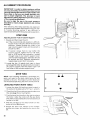
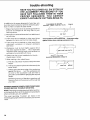
Save This Manual
For Future Reference
I
gJ _A/ S
owners
monuol
MODEL NO.
113.198410
10" DELUXE ELECTRONIC
RADIAL SAW WITH
44" CABINET AND
2 DOORS
MODEL
113,198610
OR
t13.198610
10" DELUXE ELECTRONIC
RADIAL SAW WITH
44" CABINET AND
6 DRAWERS
Serial
Number
Model and serial numlc_rs
may b_ found at the rear of
the bas_.
You should record both
model and serial number in
a safe place for future us_.
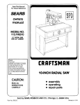
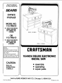
MODEL
113.198410
CRRFTSMRN
IO-INCH DELUXEELECTRONIC
RADIAL SAW
CAUTION:
READALL
INSTRUCTIONS
CAREFULLY
• assembly
• operating
• repair parts
Sold by SEARS,ROEBUCKAND CO., Chicago,
Part No. SP5013
IL. 60684 U.SJK.
Printed in U.S.A
FULL ONE YEAR WARRANTY ON CRAFTSMAN
If within one year from the date of purchase,
workmanship,
Sears
will
WARRANTY
SERVICE
CENTER/DEPARTMENT
repair
this Craftsman
RADIAL SAW
Radial Saw fails due to a defect
in material
or
it, tree of charge.
IS AVAILABLE
THROUGHOUT
BY SIMPLY
CONTACTING
THE UNITED
STATES.
THE
NEAREST
SEARS
SERVICE
This warranty applies only while this produc! is used in the United States.
This warranty gives you specific legal rights and you may also have other rights which vary from state to state.
SEARS, ROEBUCK
GENERAL
SAFETY
AND CO., DEPT. 698/731A
Sears Tower, Chicago, IL 60684
INSTRUCTIONS
1. KNOW YOUR POWER TOOL
Read and understand the owner's manual and
labels affixed to the tool. Learn its application
and limitations as well as the specific potential
hazards peculiar to this tool.
2. GROUND ALL TOOLS
This tool is equipped
with an approved
3-conductor cord and a 3-prong grounding type
plug to fit the proper grounding type receptacle.
The green conductor in the cord is the grounding
wire. Never connect the green wire to a live
terminal.
3. KEEP GUARDS IN PLACE,
in working order, and in proper adjustment and
alignment.
4. REMOVE ADJUSTING KEYS AND WRENCHES
Form habit of checking to see that keys and
adjusting wrenches are removed from tool before
turning it on.
5. KEEP WORK AREA CLEAN
Cluttered areas and benches invite accidents.
Floor must not be slippery due to wax or sawdust.
6. AVOID DANGEROUS ENVIRONMENT
Don't use power tools in damp or wet locations or
expose them to rain. Keep work area well lighted.
Provide adequate surrounding
work space.
7. KEEP CHILDREN AWAY
All visitors should be kept a safe distance from
work area.
8. MAKE WORKSHOP CHILD-PROOF
-- with padlocks, master switches, or by removing
starter keys.
9. DON'T FORCE TOOL
It will do the job better and safer at the rate for
which it was designed.
10. USE RIGHT TOOL
Don't force tool or attachment to do a job it was
not designed for.
11. WEAR PROPER APPAREL
Do not wear loose clothing, gloves, neckties or
jewelry (rings, wrist watches) to get caught in
moving parts. Nonslip footwear is recommended.
Wear protective hair covering to contain long
hair. Roll long sleeves above the elbow.
12. USE SAFETY GOGGLES (Head Protection)
Wear Safety goggles (must comply with ANSI
Z87.1) at all times. Everyday eyeglasses only
have impact resistant
lenses, they are NOT
13.
14.
15.
16.
17.
18.
19.
20.
21.
22.
FOR POWER
TOOLS
safety glasses. Also, use face or dust mask if
cutting operation is dusty, and ear protectors
(plugs or muffs) during extended periods of
operation.
SECURE WORK
Use clamps or a vise to hold work when practical.
It's safer than using your hand, frees both hands
to operate tool.
DON'T OVERREACH
Keep proper footing and balance at all times.
MAINTAIN TOOLS WITH CARE
Keep tools sharp and clean for best and safest
performances. Follow instructions for lubricating
and changing accessories.
DISCONNECT
TOOLS
before servicing;
when changing accessories
such as blades, bits, cutters, etc.
AVOID ACCIDENTAL STARTING
Make sure switch is in "OFF" position before
plugging in.
USE RECOMMENDED
ACCESSORIES
Consult the owner's manual for recommended
accessories. Follow the instructions that accompany the accessories. The use of improper accessories may cause hazards.
NEVER STAND ON TOOL
Serious injury could occur if the tool is tipped or
if the cutting tool is accidentally contacted. Do
not store materials above or near the tool such
that it is necessary to stand on the tool to reach
them.
CHECK DAMAGED PARTS
Before further use of the tool, a guard or other
part that is damaged should be carefully checked
to ensure that it will operate properly and perform
its intended function. Check for alignment of
moving parts, binding of moving parts, breakage
of parts, mounting, and any other conditions that
may effect its operation. A guard or other part
that id damaged should be properly repaired or
replaced.
DIRECTION OF FEED
Feed work into a blade or cutter against the
direction of rotation of the blade or cutter only.
NEVER LEAVE TOOL RUNNING UNATTENDED
Turn power off. Don't leave tool until it comes to
a complete stop.
additional instructions
for radial arm saws
.e..d
3=
BEFORE
USING
€_
e--
THE SAW:
WARNING: TO AVOID MISTAKES THAT COULD
RESULT IN SERIOUS, PERMANENT INJURY, DO
NOT CONNECT POWER CORD UNTIL THE FOLLOWING STEPS HAVE BEEN SATISFACTORILY
COMPLETED:
1. Assembly
and alignment.
(See pages 12-31)
2. Examination and operating familiarity with ONOFF switch, elevation hand wheel, swivel lock,
bevel lock and rip lock, guard clamp screw,
spreader and anti-kickback
device and miter
lock. (See pages 37, 38 & 39.)
3. Review and understanding
of all safety instructions and operating procedures throughout the
manual.
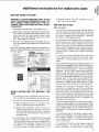
Read the following danger labels which appear on
the front of the radial arm saw base assembly, motor
and saw guard:
FOB
1
YOUR
Read
an€
before
2
s_,ely
ANSI Z87 1
6
USe
hands
he*
"PUSH
Never
reach
WHEN
RIPPING
SAFETY:
uncle(stand
3perating
Wear
3 Keep
4. Know
5
OWN
_
owner's
_anua_
-- -
machine
goggles
Ou{
o1
to
avoid
STfC
K
around
compqying
wilh
path
o¢ saw
"KICKBACKS.
blade
• for
qarrow
Ihe
saw
TO AVOID m.'NAW=Y WORKm_OE
_
_
DA_R
AT C,tn_
Returp
8fief
carriaQe
e_h
cros_
I_ the full
cul
type
befo(e
Ddiusllng
rear
posi_on
o_ration
of se_mcing
Know
1,
this
Read
2
Properly
tool.
tool:
and
Saw,
in
ttodes.
Under,land
Owners
guard
all
Manual
the
cuf_ng
warnlng_
and
wilh
an(3 instructlon_
recommended
3
Provtde
aupporl
proper
4
Positlo_
the
Ing
Ihe
construct
fence
workpl_e
to the
the
_ool
tef'_ and
yoke
SO this
the
lance;
or
an
per
o_
accea-
cutting
_rm
clamping
label
fa_n
au xill_ry
Owner's
Man-
ual
.__
5
--
b_hind power
With
the
key
1_
o 3_f
_
removed,
by hand
INSTALLING
OR
lance
off Ihe by aw+tch
mov
1urn
qo make
cutting
sure
It do_a
no_
strike
guard,
fence
or any
other
saw
fl
parts
WHEN
SAW
fence,
EACH USE
Plan your work.
-- To avoid injury from accidental starting, always
remove the plug from the outlet, turn the switch
off and remove the switch key before removing
the guard, changing the cutting tool, changing
the setup or making adjustments.
To avoid injury from blade contact, slips, shocks,
thrown pieces, etc., check the saw to make sure
that no parts are missing or broken, bent, or have
failed in any way, or any electrical component
fails to perform properly. Shut off power switch,
pull the plug from the outlet and replace damaged,
missing and/or failed parts before resuming
operation.
To avoid injury from electrical shock, make sure
your fingers do not contact the terminals when
installing or removing the plug to or from a live
outlet.
work
s shulof,po*ermad ai_ow
_aw b_.d_Io
stop
BEFORE
workpiece,
blade
? Never
perlorm
any opef|l_on
'FREEHANO
'
8
expected
contact
with the
table or part of your body.
MOVING
[[0,_,=_
THE
1. To avoid injury from unexpected carriage travel,
lock the rip lock handle before moving the saw.
2. To avoid injury from unexpected
saw movement:
(a) Bolt the saw to the floor if it tends to slip,
walk, or slide during normal operation.
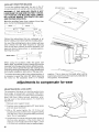
(b) When table extensions
over 24" wide are
added to either side of the saw, make sure
you either bolt the saw to the floor or support
the outer end of the extension from the floor
as appropriate.
3. To avoid injury from unexpected
carriage
travel
adjust
leveling
feet so the arm tilts
slightly
downward
to the rear so that the carriage
will not
roll forward
due to gravity.
Forward
drift of the
carriage
on an improperly
leveled
saw could
cause the blade to lunge forward
due to un-
Check the fence for proper workpiece support. To
avoid fence breakage which could result in thrown
workpieces and blade contact, do not use fences
made of particle
board or other composite
materials - use 3/4" thick lumber long enough to
extend in one piece from end to end of the saw
table, and tall enough to be at least even with the
top of the workpiece. Replace any fence where
existing slots in the fence have weakened the
fence or can snag the workpiece during ripping
operations. Always check table locks to make
sure any new fence is held securely (see page 27).
Choose your cutting tool carefully. Many saw
accidents are caused by use of the wrong type
blade, dull, badly set, improperly sharpened cutting tools, gum or resin adhering to the cutting
tools, and by blade misalignment
with the saw
fence. Such conditions can cause the material to
stick, jam (stall the saw), throw or "kickback" the
workpiece at the operator.
To avoid cutting tool failure and thrown shrapnel
(broken pieces of blade), use only blades or other
cutting tools marked for operating speeds 3450
rpm or higher. Never use a cutting tool larger in
diameter than the diameter for which the saw was
designed.
To avoid jamming of the blade, thrown workpieces, and damage to the blade collars, never
use a broken, warped, or unbalanced blade. Do
not overtighten arbor nut. Use arbor wrenches to
"snug" it securely.
To avoid injury from accidental blade contact by
the workpiece or the operator do not perform
layout, assembly, or setup work on the table
while
the cutting
tool is rotating.
The rotating
tool could cut and throw
anything
hitting
the
blade
causing
the saw to unexpectedly
come
forward.
--
--
of a second
injury.
severe, permanent
Do not cycle the motor switch "ON" and "OFF"
rapidly,
as this might
cause
the sawblade
to
loosen.
In the event this should ever occur, turn
the switch off, allow the sawblade
to come to a
complete
stop, and remove
the switch
key. To
avoid damage
to the blade and flange, retighten
the arbor nut normally,
not excessively.
--
--To
avoid injury
from
thrown
objects,
slips or
jamming
of the blade due to pinching
of the blade
by shifting
boards:
(a) Do not leavea long board unsupported
spring
of the board causes it to twist
from the table.
to inflict
If your saw makes an unfamiliar
noise or if it
vibrates excessively,
stop the operation
immediately. Do not restart until the source
has been
located
and the problem
corrected.
Use the right guard. To avoid losing control of the
workpiece,
hitting the cutting tool, or being struck
by thrown pieces, never do any cutting unless the
proper guard (with all its parts in place) is installed
and adjusted
properly.
To avoid injury from thrown
pieces, slips, blade
contact,
or jamming
of the workpiece,
make sure
no play exists between
the column
and column
support
or in the carriage
and that the arm, yoke,
bevel locks/clamps
are tight.
is sufficient
so the
or rise
(b) Check to be sure that pieces will not fall off
the table once they have been cut.
Never perform any operation
freehand.
Injury can
occur from blade contact
or thrown pieces when
the workpiece
is torn from the hands. "Freehand"
means feeding the sawblade
into a workpiece
or
feeding the workpiece
into the sawblade
or other
cutting tool without using the fence or some other
proper
device
to prevent
the workpiece
from
twisting
and binding on the cutting tool during the
cutting
operation.
(c) Provide support
for the workpiece,
based on
its size and the type
of operation
to be
performed.
(See basic saw operation
page
4O.)
-- To avoid accidental
blade contact, avoid awkward
hand positions
where a sudden slip causes a hand
to move toward
the sawblade
or other cutting
tool. Do not place fingers
or hand on the workpiece or table that is in the path of the sawblade.
(d) Never use another person as a substitute
fora
table extension,
or as an additional
support
for a workpiece
to assist in feeding, supporting, or pulling the workpiece.
-- To avoid being pulled into the back of the blade
before you can let go or react, never reach in back
of, or around the cutting
tool, with either hand to
hold down the workpiece
or for any reason.
(e) Never cut workpieces
placed
stacked
on top of each other.
slide on each other.
--
WEAR
side to side or
The pieces can
YOUR
-- The operation
of any power tool can result in
foreign objects being thrown into the eyes, which
can result in permanent
eye damage. Always wear
safety goggles complying
with ANSI Z87.1 (shown
on package).
Safety
goggles
are available
at
Sears retail catalog
stores.
Use of goggles
or
glasses not in compliance
with ANSI Z87.1 could
result in severe injury from breakage
of the eye
protection.
-- To avoid injury from uncontrollable
reaction
or
thrown
objects,
never turn the saw "ON" before
clearing
the table or work surface of all objects
(tools, scraps of wood, etc.) except the properly
supported
workpiece
and related feed or support
devices for the operation
planned.
WHENEVER
THE
SAW
IS RUNNING
-- Always keep alert. Do not allow familiarity
(gained
from frequent
use of your saw) to cause a careless
mistake. Always remember
that a careless fraction
4
To avoid injury from unexpected
starting,
never
attempt
to free a stalled
sawblade
without
first
turning
the saw "OFF" and removing
the switch
key. If the sawblade
is stalled or jammed,
shut the
saw "OFF",
remove the switch
key, remove the
workpiece,
check for looseness
in clamps,
arm
and carriage,
check the sawblade
squareness
to
the table surface and to the fence, and check for
heel (see page 29). Adjust as indicated.
-- To avoid injury from falling
parts or from falling
into the saw, never climb on or near the saw when
its power is "ON". Never leave the saw area when
power
is "ON",
or before
the cutting
tool has
come to a complete
stop.
-- To avoid unauthorized
saw use, remove the switch
key and put the key away before leaving the saw
area.
BEFORE STARTING
A RIPPING
TYPE CUT
To avoid injury from being struck by a thrown
workpiece,
position the saw so neither you, a
helper, or a casual observer is forced to stand in
line with the sawblade or workpiece.
Whenever
possible, use the "in-rip"
position.
(See
page 44.) This provides
maximum
clearance
for
feeding
by hand, push stick, or push block as
appropriate.
-- To avoid thrown workpieces
or being pulled into
the saw before you can react, push the workpiece
fromthenoseside(oppositethesawdustexhaust
chute) of the guard. Note the warningon the
guard.
--To
avoid
kickbacks
never feed a workpiece
through
the saw with another
piece
(butting
second
piece against trailing
end of piece
cut) even if of the same thickness,
-- To keep control of your workpiece,
shorter than the blade diameter.
--
-- Toavoidinjuryfromthrownpieces,slips,orjams,
theworkpiecemustbehelddownonthetableand
againstthefence.Planyour handplacementsto
safelyfeed the workpieceinto the cutting tool.
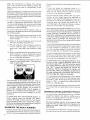
Featherboards
canalsohelpkeeptheworkagainst
thefence.Afeatherboardis madeofsolid I_Jmher
persketch.
--_ - jj
-- To avoid
'2._,'' _ i_--- _KE-RF ABOUT
accidental
blade
contact,
" - _
"_
never position
the guard
or anti-kickback
assembly
power "ON" or the blade spinning.
with
the
--
-- To avoid injury from kickback,
make sure by trial
before
starting
the cut that the anti-kickback
pawls will stop the kickback
once it has started.
Make sure points of pawls are sharp. (See page
39.) Warning:
Use extra care for non-thru
cuts
because
the anti-kickback
pawls cannot
always
grab the irregular surface created by the operation.
INSPECT
YOUR
WORKPIECE
-- To keep thesawblade
from rising up on
workpiece
and throwing
it back at the
when sawing 1/4" or thinner
materials,
normal
ripping
procedures
except set
into the table top at least 1/8".
top of the
operator,
follow all
sawblade
-- To avoid kickback,
use extra care when ripping
wood that has a twisted
grain or is twisted
or
bowed - it may rock on the table and/or
pinch the
sawblade.
If the workpiece
cannot be made stable
against the fence and table top, do not cut it with a
radial arm saw.
--
To avoid blade contact
and/or
kickback,
use a
push stick when ripping
short (10 to 12 inches
long) or narrow
(2 to 6-1/2 inches wide) workpieces. Use a push block as illustrated
on page 43
for pieces
3/8 to 2 inches
wide or, wherever
possible,
place the wider section
of the board
between the fence and the blade.
never rip work
-_=
--Plastic
and composition
(like particle
board)
materials
may be cut on your saw. However, since
these are often quite hard and slippery,
the antikickback
pawls may not stop a kickback.
To get
best performance,
rip with the finished
side down
(next to the table) and the roughest
side up, and
be especially
attentive
to follow proper set up and
cutting
procedures.
-- When properly
adjusted
to just clear the workpiece, the guard nose will help keep the workpiece
down on the table. To prevent
injury from the
workpiece
rising from the table, thrown
chips
from the workpiece
or blade, or hand slippage
towards
the front of the blade, position
the nose
guard to just clear the workpiece.
(See page 39)
-- To maximize
protection
from the rear of the blade
and avoid injury from kickbacks,
adjust the antikickback
and spreader
devices
as instructed.
(See page 31 & 39.)
"_
oo .,_
For rip or rip-type
cuts, the trailing
end of the
workpiece
to which a push stick or push board is
applied
must be square
(perpendicular
to the
fence and table top) so that feed pressure applied
to the workpiece
by the push stick or push block
will not cause the workpiece
to come away from
the fence or rise from the table and possibly
cause
a kickback.
WHILE
DOING
A RIP TYPE
OPERATION
Never reach around the blade to the
to touch
the portion
of workpiece
blade until the whole workpiece
has
beyond and clear of the blade. Your
cause a kickback
which could strike
pull your hand into the rear (outfeed
blade before you can let go or react.
outfeed side
beyond
the
been pushed
touch could
someone
or
side)
of the
-- Position
your body at the nose (in-feed)
side of
the guard. Start and complete
the cut from that
same side. This will require
added table support
for tong or wide workpieces
that extend beyond
the length
or width of the saw table to prevent
workpiece
from being thrown as it falls from the
table.
--
Never apply the feed force to the section
of the
workpiece
that will become
the cutoff
(free)
piece. Feed force when ripping
must always be
applied
between
the sawblade
and the fence so
that the slot cut by the blade (kerf) will not be
pinched
shut on the blade causing
a kickback.
Never touch the piece that has been cut off until
the blade has come to a complete
stop.
--Keep
pushing
the section
of the workplece
between
the blade and the fence until the piece
has been pushed
completely
past the blade, so
the blade will not grab the piece and throw it back
at the operator.
BEFORE
DOING
A CROSSCUT
_"._--
being
TYPE
CUT
--To
avoid
blade
contact,
do not perform
any
operation
that requires
the cutting
tool to extend
beyond the edges of the table used forsupporting
the workpiece.
--To
maximize
protection
from accidental
blade
contact
and reduce risk of jamming
objects
into
the guard,
place guard in a horizontal
position
and adjust anti-kickback
pawls to just clear the
top of the fence or the workpiece,
whichever
is
higher.
The anti-kickback
pawl assembly
will
provide additional guarding
front of the blade.
from contact with the
--To
prevent
the cutting
tool from grabbing
the
table or workpiece
and being propelled
toward
you, never lower a revolving
cutting
tool into the
table or a workpiece
without
first locking
the rip
lock handle and clamping
the workpiece
in place.
Release
the handle
only
after
having
firmly
grasped
the carriage
handle.
-- To avoid blade contact orinjuryfrom
athrown
cut
off piece, never use a length stop on the cut off
end or edge of theworkpiece.
Never hang onto or
touch the cut off piece of the workpiecewhile
the
power is "ON" and/or the sawblade
is rotating.
To
prevent pinching
that could cause the piece to be
thrown,
the cut off piece must never be confined,
pushed,
or grabbed
while the blade is spinning.
INSPECT
YOUR
-- Always
return
the carriage
to the full rearward
position
behind
the fence at the completion
of
each crosscut
type operation.
Never remove your
hand from the yoke handle unless the carriage
is
in this position.
Otherwise,
the cutting
tool may
climb
up on the workpiece
and be propelled
toward you.
BEFORE
DOING
The use of grinding
wheels, abrasive
or cut off
wheels, or wire wheels, can be dangerous
and are
not recommended.
Such devices can break explosively
injury.
--Always
position
start with the carriage
behind the fence before
TYPE CUT
in the
turning
throw
shrapnel,
causing
severe
Using a drill chuck. To avoid injury from sudden
bending
or breaking
of a drill bit, do not install or
use twist drills longer than 7" in length or extending more than 6" beyond the chuck jaws. Do not
install or use any reduced
shank drill except the
spade
type (1" diameter
or smaller).
Use for
drilling
wood or plastic only - bit speed cannot be
properly
adjusted
for other materials.
Do not use
twist drills larger than 1/2" in diameter.
full rear
the saw
On.
--
and
The sawblade,
dado, or other cutting tool must be
removed
from the saw arbor
before
using the
accessory
shaft.
Never operate
the saw with
cutting
tools
(including
sanding
accessories
or
buffing)
instal led on both ends of the saw arbor to
avoid being
pulled
into moving
parts by hair,
threads,
clothing,
etc. Make sure the unused
arbor is always covered by a guard, the arm, or the
screw cap.
WORKPIECE
A CROSSCUT
ACCESSORIES
To avoid injury from unanticipated
hazards, use
only recommended
accessories
as listed on page
57.
--To
avoid
injury from
thrown
objects,
slips or
jamming
of the blade, make sure the workpiece
wilt fit the supports
(fence, table, fixtures
or jigs)
so it will not twist, rock or otherwise
bind on the
cutting
too!. Make sure there is no sawdust
or
other foreign material between the workpiece
and
its support.
WHILE
USING
Never push the carriage
and blade backwards
into the work to do a crosscutting
type operation.
The cutting
tool can throw
the work
over the
fence, striking someone
or causing you to fall into
the blade.
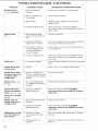
glossary of terms for woodworking
Anti-Kickback Pawls (AKB)
Device which, when properly adjusted, is designed
to stop the workpiece from being kicked back at the
operator during ripping operations. See illustrations
on pages 31 & 39.
A sticky,
sap based
residue
from
wood
products.
Heel
Misalignment
of the blade.
See page
30.
In-Rip
Arbor
The shaft
Gum
on which
a cutting
tool
Positioning
the blade parallel to the fence with the
motor toward the front of the saw. See illustration
on
page 44.
is mounted.
Crosscut
A cutting
or shaping
width of the workpiece.
40-42.
operation
made
See illustrations
across
the
on pages
The amount
of material
removed
through
cut or the slot produced
non-through
or partial cut.
Dado
A non-through
notch or trough
cut which produces
in the workpiece.
a square
sided
Featherboard
A device which
can assist
during rip type operations.
Kerf
in guiding
workpieces
Freehand
Performing
a cut without
the use of fence (guide),
hold down or other proper
device to prevent
the
workpiece
from twisting
during
the cutting
operation. Twisting
of the workpiece
can cause it to be
thrown
or kicked back by a radial saw.
by the blade
by the blade
in a
in a
Kickback
An uncontrolled
grabbing
and throwing of the workpiece back toward the operator
during
a rip type
operation.
Leading
End
The end of the workpiece
which, during a rip type
operation,
is pushed into the cutting
tool first.
Molding
A non-through
cut which produces
a special shape
in the workpiece
used for joining
or decoration.
Outrip
Positioningthe bladeparallelto the fencewith the
motor towardthe rearof the sawproducingmaximumrippingcapacity.Seeillustrationon page42.
PushStick
A deviceusedto feedtheworkpiecethroughthesaw
duringnarrowrippingtypeoperationsso the operator'shandsarekeptwellawayfromthe blade.See
page43.
Push Block
A device used for ripping type operations
too narrow
to allow use of a push stick. See page 43.
Rabbet
A notch
in the edge
that has hardened.
Ripping
A cutting
piece.
operation
Revolutions
along
Per Minute
The number of turns
in one minute.
the
length
of the work-
(RPM)
completed
by a spinning
object
electrical
POWER
The area of the workpiece
or table top directly
in line
with either the travel of the blade or the part of the
workpiece
which
will be, or has been, cut by the
blade.
Set
The distance
that the tip of the sawblade
tooth
bent (or set) outward
from the face of the blade.
SUPPLY
Throwing
kickback.
used in this saw is a capacitor-start,
type having the following
specifica-
Rated H P....................................
Maximum
Developed
H.P ....................
Voltage .................................
Amperes
.................................
Hertz (cycles) ................................
Phase ....................................
RPM ......................................
Rotation
of Blade Arbor
...............
of small
pieces
in a manner
similar
to a
o
Thru-Sawing
End
The workpiece
operation.
end last cut by the blade
in a ripping
Workpiece
The item on which
the cutting
operation
is being
performed.
The surfaces
of a workpiece
are commonly referred to as faces, ends, and edges.
connections
POWER CORD IS WORN OR CUT, OR DAMAGED
IN ANY WAY, HAVE IT REPLACED IMMEDIATELY.
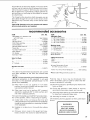
1. Motor Specifications
The A-C motor
non-reversible
tions:
is
Throw-Back
Trailing
sap base substance
Path
Any cutting
operation
where
the blade extends
completely
through
the thickness
of the workpiece.
of a workpiece.
Resin
A sticky,
Sawblade
1.5
2.75
120/240
11/5.5
60
Single
3450
Clockwise
WARNING:
TO AVOID
ELECTRICAL
HAZARDS,
FIRE HAZARDS,
OR DAMAGE TO THE TOOL, USE
PROPER
CIRCUIT
PROTECTION.
YOUR SAW IS
WIRED AT THE FACTORY
FOR 120V OPERATION.
CONNECT
TO A 120V, 15-AMP, BRANCH CIRCUIT
AND
USE A 15-AMP,
TIME
DELAY
FUSE
OR
CIRCUIT
BREAKER.
IF THE MOTOR
IS REWIRED
FOR 240V OPERATION,
CONNECTTO
A CIRCUIT
PROTECTED
BY 15-AMP, DUAL ELEMENT
TIMEDELAY FUSE OR CIRCUIT
BREAKER.
IF NOT PROPERLY
GROUNDED
THIS
POWER
TOOL
CAN
CAUSE
ELECTRICAL
SHOCK
PARTICULARLY
WHEN USED IN DAMP LOCATIONS
IN PROXIMITY
TO PLUMBING.
IF AN
ELECTRICAL
SHOCK
OCCURS
THERE IS ALSO
THE POTENTIAL
OF A SECONDARY
HAZARD
SUCH
AS YOUR
HANDS
CONTACTING
THE
SAWBLADE.
NOT ALL OUTLETS
ARE PROPERLY
GROUNDED.
TO AVOID
SHOCK
OR FIRE,
IF
If you are not sure that
grounded,
have it checked
your outlet
by a qualified
If your unit is for use on less than
plug that looks like below.
3-PRONG
is properly
electrician.
150 volts
it has a
PLUG
PROPERLY
GROUNDED
OUTLET
GROUNDING
PRONG
This power tool is equipped with a 3-conductor cord
and grounding
type plug which has a grounding
prong, listed by Underwriters'
Laboratories.
The
ground conductor has a green jacket and is attached
to the tool housing at one end and to the ground
prong in the attachment plug at the other end.
This plug requires a mating 3-conductor
type outlet as shown above.
grounded
WARNING: TO MAINTAIN PROPER TOOL GROUNDING WHENEVER THE OUTLET YOU ARE PLANNING TO USE FOR THIS POWER TOOL IS OF THE
TWO PRONG TYPE, DO NOT REMOVE OR ALTER
THE GROUNDING PRONG IN ANY MANNER. USE
AN ADAPTER AS SHOWN AND ALWAYS CONNECT THE GROUNDING
PRONG TO KNOWN
GROUND.
It is recommended
that you have a qualified
electrician replace
the two prong outlet with a properly
grounded
three prong outlet.
b. Using
a small screwdriver,
switch
to 240V position.
cover panel.
DUAL
An adapter as shown below is available
for connecting plug to 2-prong
receptacles.
The green grounding lead extending
from the adapter
must be connected to a permanent
ground such as to a properly
grounded
outlet box.
slide dual voltage
Then replace
motor
VOLTAGE
SWITCH
L
GROUNDING LUG
ADAPTER
/
"\ _
3-PRONG
PLUG
MAKE
_r_/._.._,_
SURE
KNOWN
THIS
IS
GROUND
__ONNECTED
TO
A
RECEPTACLE
WARNING: THE ADAPTER ILLUSTRATED IS FOR
USE ONLY IF YOU ALREADY HAVE A PROPERLY
GROUNDED 2-PRONG RECEPTACLE.
ELECTRICAL
CONNECTIONS
WARNING: CHANGES IN ELECTRICAL CONNECTIONS SHOULD BE MADE BY A QUALIFIED
ELECTRICIAN.
240V
PLUG
& RECEPTACLE
Under
normal
home workshop
usage, and if
proper
(full) voltage
is supplied
to the motor,
your
saw will operate
efficiently
on 120V, as
connected
at the factory.
However,
if any of the
following
conditions
exists, it will be advisable
for you to reconnect
the motor for 240V operation - to obtain the efficiency
and performance
for which your saw is designed:
(1) Heavy-duty
(2) Either
circuit
an undersized
oran overloaded
serving the saw motor.
a. Remove
motor.
for 120V A.C.
motor
cover
panel
b. Using
small
screwdriver,
switch
to 120V position.
cover panel.
c. Use 120V power
3. Connection
a. Remove
motor.
ADAPTER
IS
AVAILABLE
FOR
THIS TYPE PLUG
d. Plug your
receptacle.
branch
The procedures for changing the motor voltage
(factory set for 120V) are described below. Whenever changing the switch position from 120V to
240V or vice-versa, make certain that all necessary steps (including proper fusing of the branch
circuit) are completed.
2. Connections
GROUNDED
OUTLET
BOX
operations.
(3) Low voltage
supplied
by the power source,
which the power company
cannot correct.
b.
power
cord plug with a (3
plug (see illustration
below).
cord white and black leads,
two "hot" plug blades - and
cord grounding
wire to the
GROUNDING
BLADE
IS
LONGEST
OF 3 BLADES
1. Changing Motor Voltage
a,
c. Replace
the 120V
blade) 240V 15 Amp
Connect
the power
respectively,
to the
connect
the power
plug ground
prong.
cord
at
blade
end
of
slide
dual voltage
Then replace
motor
furnished
with your
saw.
for 240V A.C.
motor
cover
panel
at
blade
end
of
saw
into
a 240V,
15-Amp,
3-blade
e. Make certain
the receptacle
is connected
to a
240V A-C power supply through
a 240V branch
circuit
having
at least a 15-amp
capacity
and
protected
by a 15-amp time-delay
fuse or circuit
breaker.
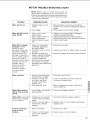
MOTOR
SAFETY
PROTECTION
CAUTION:
TO AVOID
MOTOR
DAMAGE
THIS
MOTOR SHOULD BE BLOWN OUT OR VACUUMED
FREQUENTLY
TO PREVENT
SAWDUST
BUILDUP
WHICH WILL INTERFERE
WITH NORMAL MOTOR
VENTILATION.
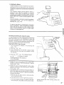
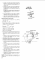
Your saw is equipped
with a manual-reset
thermaloverload
protector
designed
to open the power line
circuit
when the motor temperature
exceeds a safe
level, motor is overloaded
or a low voltage condition
exists.
1
_
)MANUAL
RESET
BUTTON
1. If the protector
opens the line and stops the saw
motor,
immediately
turn the saw switch "OFF",
remove the key and allow motor time to cool.
tages not more than 10% above or below the
nameplate
voltage.
Heavy
loads,
however,
require that voltage at motor terminals
equals
the voltage specified
on nameplate.
2. After cooling
to a safe operating
temperature,
the overload
protector
can be closed manually
by pushing
the red button
on the top of the
motor.
If the red button will not click into place
immediately,
the motor is still too hot and must
be allowed to cool for a while longer.
5. Most motor troubles
may be traced to loose or
incorrect
connections,
overloading,
reduced
input
voltage
(such
as small size wire in the
supply
circuit)
or to overly long supply
circuit
wire. Always
check
the connections,
the load
and the supply
circuit
whenever
motor fails to
perform
satisfactorily.
Check
wire sizes and
length with the Wire Size Chart below.
If the motor,
after hard,
long use trips
the
overload
protector,
the time equal to the thermal
build up before the trip may be needed to cool
the motor before the overload
protector
can be
reset. An audible
click will indicate
protector
is
closed (reset).
WIRE
The use of any extension
cord will cause some loss
of power. To keep this to a minimum
and to prevent
over-heating
and motor
burn-out,
use the table
below to determine
the minimum
wire size (A.W.G.)
extension
cord. Use only 3 wire extension
cords
which have 3 prong grounding
type plugs and 3-pole
receptacles
which accept the tools plug.
3. As soon as the red button will click into running
position, the saw may be started and operated
normally.
4. Frequent "blowing" of fuses or tripping
breakers may result if:
SIZES
of circuit
(a) MOTOR IS OVERLOADED
- Overloading
can
occur
if you feed too rapidly
or if saw is
misaligned
so that the blade heels (pg. 29)
(b) MOTOR CIRCUIT
IS FUSED DIFFERENTLY
FROM RECOMMENDATIONSAlways follow
instructions
for the proper fuse/breaker.
Do
not use a fuse/breaker
of greater
capacity
without
consulting
a qualified
electrician.
CAUTION:
For circuits that are farther away from
electrical service box, the wire size must be increased
proportionately
in order to deliver ample voltage to
the saw motor.
Length
of the
Conductor
Wire Sizes
(American
Wire
240V
(c) LOW VOLTAGE
- Although
the motor
is
designed
for operation
on the voltage
and
frequency
specified
on motor
nameplate,
normal
loads will be handled
safely on vol-
0 - 50 Feet
50 - 100 Feet
Over 100 Feet
Required
Gage Number)
Lines
120V Lines
No. 16
_
No. 14
14
No. 12
t
No.
No. 12
8
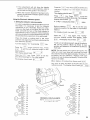
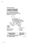
location and function of controls
DIGITAL
PANEL
ON-OFF
BLADE
READOUT
RIP LOCK
HANDLE
SWITCH
GUARD
. YOKE
HANDLE
MITER
LOCK
HANDLE
AKB/SPREADER
WING SCREW
GUARD
CLAMP
SCREW
TABLELOCK
HANDLES
OOTACTUATOR
SWIVEL
LOCK
HANDLE
°i
i..u
t..3
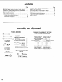
contents
Guarantee
Page
2
....................................
General Safety Instructions for Power Tools .... 2
Additional Safety Instructions for Radial Saws .. 3
Glossary
Electrical
of Terms for Woodworking
Connections
........................
...........
Assembly and Alignment .....................
Unpacking and Preassembly ................
Alignment Procedure .......................
6
7
10
11
26
Page
Location
and Function
of Controls
............
40
46
50
Maintenance
.................
56
Recommended
Accessories ...................
Repair Parts .................................
57
58
and Lubrication
assembly and alignment
TOOLS
NEEDED
FRAMING
@
Check
MEDIUM
CHECKING
INSIDE
SCREWDRIVER
REAR
7/16" WRENCH
1/2" WRENCH
3/4" WRENCH
3/4" SOCKET
9/16" SOCKET
7/16" SOCKE'f
#2 PHILLIPS
SCREWDRIVER
FRAMING
SQUARE
PENCIL
SOCKET
SOCKET
lo
EXTENSION
WRENCH
1/8" HEX "L" WRENCH
3/16" HEX "L" WRENCH
36
Basic Saw Operations ........................
Adjustments to Compensate for Wear .........
Trouble Shooting ............................
DRAW
TABLE
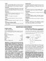
EDGE
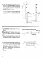
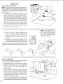
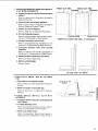
SQUARE MUST BE TRUE.
its accuracy
ACCURACY
OF SQUARE
OF
FRONT
(FENCE,
SPACER
AND
BOARDS
REMOVED)
LINE
ON
/
THIS
EDGE
_
OF
as illustrated
CHECKING
OUTSIDE
below.
ACCURACY
OF SQUARE
OF
TABLE
BACK
LIGHT
ALONG
SHOULD
BE NO GAP
OR
OVERLAP
HERE
WHEN
SQUARE
IS FLIPPED
OVER
IN DOTTED
POSITION
_
FENCE
_
/t
I
/
DRAW
I_JL_TABLE
_
_
LIGHT
ALONG
i
LINE
ON
THIS
EDGE
SHOULD
BE NO GAP
OR
OVERLAP
HERE
WHEN
SQUARE
IS FLIPPED
OVER
IN DOTTED
POSITION
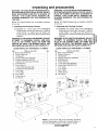
unpacking and preassembly
WARNING: TO AVOID INJURY FROM UNEXPECTED STARTING OR ELECTRICAL SHOCK, DO NOT
PLUG THE POWER CORD INTO A SOURCE OF
POWER.
THIS CORD
MUST
REMAIN
UNPLUGGED WHENEVER YOU ARE WORKING ON
THE SAW.
WARNING: TO AVOID INJURY FROM UNEXPECTED STARTING OR ELECTRICAL SHOCK, DO NOT
PLUG THE POWER CORD INTO A SOURCE OF
POWER.
THIS CORD
MUST
REMAIN
UNPLUGGED WHENEVER YOU ARE WORKING ON
THE SAW.
Model 113.198410 Radial Saw is shipped
in one box.
Model 113.198610 Radial Saw is shipped
in one box.
complete
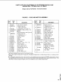
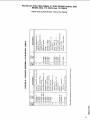
1. Unpacking and Checking Contents
1. Unpacking and Checking Contents
(a) Separate all "loose parts from packaging
materials and check each item with "Table of
Loose Parts" to make sure all items are
accounted for, before discarding any packing
material.
WARNING: IF ANY PARTS ARE MISSING, DO NOT
ATTEMPT
TO ASSEMBLE RADIAL ARM SAW,
PLUG IN THE POWER CORD, OR TURN THE
SWITCH ON UNTIL THE MISSING PARTS ARE
OBTAINED AND ARE INSTALLED CORRECTLY.
Table
A
B
C
D
E
F
G
H
I
J
K
L
M
N
O
of Loose
Parts
Basic Saw Assembly ...................
Owner's Manual .......................
Handwheel ............................
Cabinet Assembly #507487 .............
Drawer Assembly #507537 .............
Caster/Foot Assembly #507538 .........
Shaft Wrench .........................
Arbor Wrench .........................
Loose Parts Bag #507488 ..............
Loose Parts Bag #507532 ..............
Trim Caps ............................
Trim Ledge ...........................
Rear Table ............................
Table Spacer ..........................
Rip Fence .............................
(a) Separate all "loose parts from packaging
materials and check each item with "Table of
Loose Parts" to make sure all items are
accounted for, before discarding any packing -m
e"
t.. ,
material._
_= ,-WARNING: IF ANY PARTS ARE MISSING, DO NOT
ATTEMPT TO ASSEMBLE RADIAL ARM SAW,
PLUG IN THE POWER CORD, OR TURN THE
SWITCH ON UNTIL THE MISSING PARTS ARE
OBTAINED AND ARE INSTALLED CORRECTLY.
._
E ==
_
ra_
<:
LOOSE PARTS LIST FOR MODEL 113.198410
LOOSE PARTS LIST FOR MODEL 113.198610
Item
complete
Qty.
Item
1
1
1
1
1
1
1
1
t
1
2
1
1
!
1
A
B
C
D
E
F
G
H
I
J
K
L
M
Table
of Loose
Parts
Basic Saw Assembly ...................
Owner's Manual .......................
Handwheel ............................
Cabinet Assembly #507490 .............
Shaft Wrench .........................
Arbor Wrench .........................
Loose Parts Bag #507491 ..............
Loose Parts Bag #507532 ..............
Trim Caps ............................
Trim Ledge ...........................
Rear Table ............................
Table Spacer ..........................
Rip Fence .............................
Qty.
1
1
1
1
1
1
1
1
2
1
1
1
1
o
0
NOTE: Loose Parts Bag and Assembly Numbers
refer to three digits, underlined in example below, or
the I.D. Number printed on each bag or carton.
X04507488H000
'11
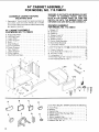
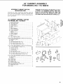
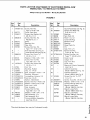
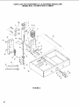
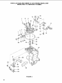
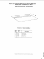
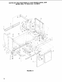
44" CABINET ASSEMBLY
FOR MODEL NO. 113.198610
WARNING: IF ANY PARTS ARE MISSING, DO NOT
ATTEMPT TO ASSEMBLE RADIAL ARM SAW,
PLUG IN THE POWER CORD, OR TURN THE
SWITCH ON UNTIL THE MISSING PARTS ARE
OBTAINED AND ARE INSTALLED CORRECTLY,
ASSEMBLE
CABINET BEFORE
MOUNTING
SAW
1. Separate all "loose" parts from packing materials
and check each item with "Parts List" to make
sure all items are accounted
for before discarding
any packing
material.
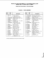
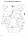
44" CABINET
FOR MODEL
A
B
C
D
E
F
G
H
I
J
K
L
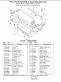
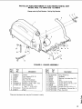
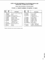
DRAWER ASSEMBLY
FOR MODEL NO. 113.198610
ASSEMBLY
NO. 113.198610
Right Side Panel ............................
Left Side Panel .............................
Lower Shelf ................................
Under Support
.............................
Skirt .......................................
Shelf Stiffener
..............................
Corner Bracket .............................
Lower Support
.............................
Rear Support ...............................
Upper Support
.............................
Front Support
..............................
Shelf Stiffener
Rear .........................
1
1
1
1
2
1
4
1
3
1
1
1
J
I
L
M
N
O
P
Q
R
S
T
Drawer 10". ................................
Drawer 6" . ................................
Drawer 3". .................................
Drawer Front 10". ..........................
Orawer Front 6" . ...........................
Drawer Front 3". ...........................
Center Slide Brackets ......................
Stand Slide Brackets .......................
Lubrication
Packet ..........................
Loose
U
V
W
X
Y
Z
Parts
Bag No. 507488
Drawer Fastener
Truss Head Bolt
Hex Nut 1/4-20
Lockwasher
1/4
Pan Head Type
Pan Head Screw
contains
2
2
2
2
2
2
12
12
2
the following:
...........................
1/4-20 x 1/2 ...............
............................
...........................
"BT" Screw 1/4-14 x 1/2 ......
No. 10 x 1 ..................
48
82
82
82
8
6
O.P.Q
T
W
X
Y
Z
U
G
A
F
B
C
D
Loose
E
12
F
G
H
A.
B.
C.
D.
E.
F.
G.
H.
Parts
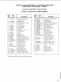
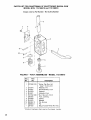
Bag No. 507664
contains
the following:
Yoke Plug ..................................
Battery
....................................
Switch Key .................................
Blade Guard Rear Bumper Pad ..............
Plastic Plug ................................
Motor Support Cap .........................
Pan Head Screw 10-32 x 1/2 ................
Washer Ext. No. 10 .........................
1
1
1
1
4
1
1
1
CASTER/FOOT
ASSEMBLY
NO. 50753____8
A R.H. Foot Assembly .........................
B L.H. Foot Assembly .........................
C Caster .....................................
Loose
D
E
F
F
G
H
I
Parts
Bag No. 50752___2
contains
1
1
4
the following:
Slotted Truss Head Bolt 1/4-20 x 7/16 .......
Truss Head Bolt 1/4-20 x 1 ..................
Hex Nut 1/4-20 ............................
Hex Nut 1/2-13 .............................
Lockwasher
1/4 ............................
Spacer .....................................
Foot-Leveling
..............................
20
2
18
2
18
2
2
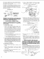
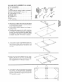
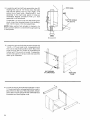
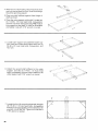
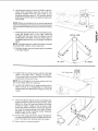
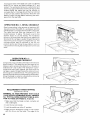
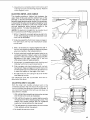
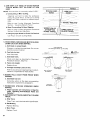
2. After layout of stand parts, take the lower shelf
and turn upside down on floor. Small front flange
should
be pointing
upward.
3. Place one shelf
shelf as shown.
stiffener
against
front
flange
E_
of
4. Place the under support on the shelf. Locate two
(2) 1/4-20 x 1/2 truss head bolts, Iockwashers
and hex nuts from loose parts bag #488. Attach
the supports
to the shelf in holes as illustrated
and tighten nuts with 7/16" wrench or socket.
5. Locate lower support
and assemble
lower support, shelf and under shelf support
with four (4)
1/4-20 x 1/2 truss head bolts, Iockwashers,
and
hex nuts.
i
6. Attach
the second
shelf
stiffener
to the
under
support.
Use two (2) 1/4-20 x 1/2 truss head
bolts, Iockwashers,
and hex nuts to fasten to the
under support
with 7/16" wrench
or socket.
7. Locate the four (4) corner brackets and use eight
(8) 1/4-20 x 1/2 truss head bolts, Iockwashers
and hex nuts to mount the corner brackets to the
shelf AS ILLUSTRATED.
Tighten
the nuts with a
7/16" wrench or socket.
13
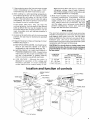
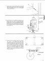
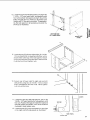
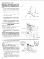
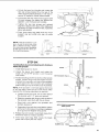
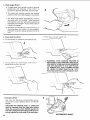
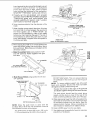
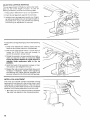
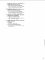
8. Locate the right and left foot assemblies, two (2)
leveling feet, two (2) 1/2-13 hex nuts, the right
and left side panels, and four (4) 1/4-20 x 7/16
slotted truss head bolts. Attach theR.H, foot
assembly to the right side panel in holes as
illustrated.
Repeat procedure
with L.H. foot
assembly to left side panel.
J
SIDE
PANEL
SLOTTED SCREW
1/4-20x 7/16
Thread the 1/2-13 hex nuts onto the leveling feet
studs. Insert the threaded studs of the leveling
feet into the tubes in the foot assemblies.
NOTE: Make certain foot actuator is locked in its
down position before it is inserted through opening
in side panels.
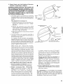
9. Locate the right and left side panels and eight (8)
1/4-20 x 1/2 truss head bolts, Iockwashers
and
hex nuts to attach side panels to shelf. Mount the
bolts through
the four holes as illustrated
and
tighten with 7/16 wrench or socket. To assemble,
lay the side panel on its back side and stand the
shelf up as illustrated.
s
/
BOTTOM SIDE
OF LOWER SHELF
RIGHT SIDE
PANEL
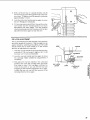
10. Locate the two (2) skirts and the eight (8) 1/4-20x
1/2 truss head bolts, Iockwashers
and hex nuts to
attach them to the top of the side panels. Attach
one to the front and one to the rear of the stand as
illustrated
and hand
tighten
nuts.
\.\
\
14
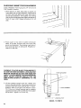
11.Securerearof lowershelf to right sideandleft
sidepanelsusingtwo (2)1/4-20x 1/2trusshead
bolts, Iockwashersand hexnuts. Handtighten
nutsonlyatthis time.
l'_
SIDE
J
12. Lay the stand on the backside, locate two (2)
spacers, two (2) 1/4-20 x 1"truss head bolts,
Iockwashers and hex nuts. Assemble the spacers
between each of the foot assemblies and the
lower shelf on each side with one (1) truss head
bolt, Iockwasher and hex nut each as illustrated.
Hand tighten nut.
PANEL
SHELF
1/4-20
x 1
SPACER
13. Locate
the four (4) swivel
casters
and sixteen
(16) 1/4-20
x 7/16 slotted
truss
head
bolts,
Iockwashers,
and hex nuts. Line up the caster
with the matching
holes in lower shelf and corner
bracket
(shaded
area). Attach
the caster with
four (4) slotted
truss head bolts, Iockwashers
and hex nuts and tighten
by hand as illustrated.
When all four bolts are installed
use a regular
screwdriver
and a 7/16"
wrench
or socket
to
tighten securely.
Repeat procedure
for the three
remaining
casters.
l
1/4"-20 x 7/16"
LOCKWASHER
HEX
NUT
r--
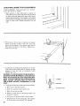
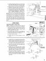
CHECKING
CABINET
FOR SQUARENESS
ii
TOOLS NEEDED: Framing square, 3/4" wrench and
7/16" wrench or socket.
1. With cabinet on back side place a square on
lower shelf next to right side panel. Adjust stand
so both right side panel and lower shelf touch
square (as illustrated). Then tighten nut holding
rear of shelf to side panel and right side spacer to
front of lower shelf. Repeat procedure for left
side.
2. Place
stand
panel
front
cedure
square at top side of cabinet
and adjust
so square
touches
both skirt and side
(as illustrated).
Then tighten
right side of
and rear skirts to side panel. Repeat profor left side.
WARNING: TO AVOID INJURY FROM UNEXPECTED SAW OR WORK MOVEMENT, LEVELING FEET
MUST BE ADJUSTED SO THAT SAW DOES NOT
ROCK. TO AVOID UNEXPECTED CARRIAGE MOVEMENT, ADJUST LEVELING FEET SO THAT THE
ARM SLOPES SLIGHTLY DOWNWARD
TO THE
REAR.
FOOT
ACTUATOR
3. Lift the cabinet
upright
onto the casters
and
move to desired location.
Press down on the foot
actuator
pedal and lock leveling feet in "down"
position.
With a 3/4 open end wrench
loosen
1/2-13 hex nut. Adjust
leveling feet by rotating
counterclockwise
until foot lifts the front caster
off the floor - tighten
1/2-13 hex nut.
HEX
NUT
LEVELING
FOOT
MODEL 113.198610
16
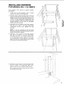
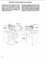
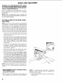
INSTALLING
FOR MODEL
Tools needed:
screwdriver.
1. Locate
support,
7/16"
DRAWERS
NO. 113.198610
wrench
or socket,
one (1) front
support,
one
and three (3) rear supports.
medium
(1)
upper
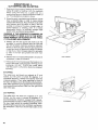
2. Slide the upper support
into the top of the front
support
so the top and side holes line up. Then
assemble to the front and rear skirts with four (4)
1/4-20 x 1/2 truss head bolts, Iockwashers,
and
hex nuts. Position
bolts from bottom
side with
threads
upwards
on front skirt as illustrated.
Tighten
hex nuts securely.
r-,//
NOTE:
It may be necessary
to tilt
backwards
to tighten the bolts holding
support to the lower support.
E==
/
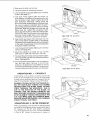
3. Assemble
the front support
to the lower support
with two (2) 1/4-20
x 1/2 truss
head
bolts,
Iockwashers
and hex nuts. Tighten
hex nuts
securely.
the stand
the center
4. Assemble a rear support to the lower support
with two (2) 1/4-20 x 1/2 truss head bolts,
Iockwashers and hex nuts. Tighten nuts securely.
Do not assemble the rear support to the upper
support at this time. These holes are used in Step
#6 to attach the stand slide bracket.
/
(3
5. Assemble
four
(4)
washers,
a rear support
to each side panel with
1/4-20
x 1/2 truss head bolts,
lockand hex nuts. Tighten
nuts securely.
Rear support
must touch
line up with front holes.
lower
shelf
for holes to
17
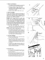
6. Locate the twelve (12) stand slide brackets,
twenty-four
(24) truss head bolts, Iockwashers
and hex nuts. Assemble the stand slide brackets
on the rear supports and inside of the side panels
in holes as illustrated. Assemble the stand slide
brackets on the center and rear supports in holes
as illustrated starting at the top.
o_
The rear mounting hole in the stand slide bracket
is slightly enlarged and must be mounted to the
rear support for stand slide stops to work. Tighten
nuts securely.
TO
7. Locate the twelve (12) center slide brackets and
the two (2) lubrication packets. Lubricate upper
& lower channel on all twelve (12) center slide
brackets,
CABINET
SLIDE
BRACKETS
STOP
TO THIS
SIDE
REAR
NOTE: In order for drawer stops to work, the center
slide bracket must be assembled as illustrated.
Failure to do so may result in drawer sliding off slide
brackets.
8. Insert center slide brackets into the stand slide
brackets. Center slide brackets should snap over
front stop when pushed on stand slide bracket.
9. Locate the metal drawer, drawer fronts and the
bag of drawer front push-in type fasteners. Slide
drawer fronts onto appropriate size drawer. Make
sure the drawer front tabs engage the metal
drawer edges. Align holes and install push-in
type fasteners to assemble front to metal drawer.
Be sure all fasteners clamp the drawer front
firmly to the metal drawer.
10. Set drawer
page 24.
18
assemblies
aside until called for on
DRAWER
/
/
STOP
TO THIS
SIDE
STOP
44" CABINET ASSEMBLY
FOR MODEL NO. 113.198410
ASSEMBLE
CABINET
MOUNTING
BEFORE
Separate
all "loose"
parts from
and check each item with "Parts
all items are accounted
pack_ng material.
44" CABINET
FOR MODEL
A
B
C
D
E
F
G
H
I
J
K
L
AH
packing
materials
List" to make sure
for before
ASSEMBLY
WARNING:
IF ANY PARTS ARE MISSING,
DO NOT
ATTEMPT
TO ASSEMBLE
RADIAL
ARM SAW,
PLUG
IN THE POWER
CORD,
OR TURN
THE
SWITCH
ON UNTIL
THE MISSING
PARTS ARE
OBTAINED
ARE ARE INSTALLED
CORRECTLY.
SAW
discarding
any
#507490
NO. 113.198410
Right Side Panel .........................
Left Side Panel ...........................
Lower Shelf ..............................
Under Support
...........................
Skirt .....................................
Shelf Stiffener
...........................
Corner Brackets
.........................
1
1
1
1
2
1
4
Lower Support
...........................
Spacer
..................................
Upper Support
...........................
Front Support ............................
Door ....................................
Shelf Stiffener
Rear ......................
1
2
1
1
2
1
Loose Parts Bag #507533 contains
the following:
M Magnetic
Catch ..........................
N Hinge
...................................
O Pan Head Screw #6 x 1/2 .................
P Pan Head Screw #10 x 1/2 ................
Q Pan Head Screw #6-32 x 3/8 ..............
2
4
4
8
4
Loose Parts Bag #507491 contains
the following:
R Truss Head Bolt 1/4-20 x 1/2 .............
S Hex Nut 1/4-20 ..........................
T Lockwasher
1/4 .........................
66
66
66
U
V
W
X
Leveling
Foot ............................
Hex Jam Nut 1/2-13 ......................
Pan Head Type"BT"
Screw 14 x 1/2 .......
Pan Head Sheet Metal Screw #10 x 1 ......
4
8
8
6
Loose Parts Bag #507532 contains
the following:
Y Yoke Plug ...............................
Z Battery
..................................
AA Switch Key ..............................
AB Guard Pad ...............................
AC Plastic Plug ..............................
AD Mot.or Support
Cap .......................
AE Pan Head Screw 10-32 x 1/2 ..............
AF Washer Ext. #10 ..........................
AG Cover ...................................
1
1
1
1
4
1
1
1
2
¢
/
G
L_
jJ
Z
AB
AA
AF
AC
AD
AG
AE
19
2.Afterlayoutofstandparts,takethe bottomshelf
andturn upsidedownonfloor.Smallfrontflange
shouldbe pointingupward.
3. Place one shelf stiffener
shelf as shown.
r
against front flange of
4. Place the under support on the shelf. Locate two
(2) 1/4-20 x 1/2 truss head bolts, Iockwashers
and hex nuts from loose parts bag #488. Attach
the supports
to the shelf in holes as illustrated
and tighten nuts with 7/16" wrench or socket.
5. Locate lower support
and assemble
lower support, shelf and under shelf support
with four (4)
1/4-20 xl/2
truss head bolts, Iockwashers,
and
hex nuts.
_C_J
6. Attach
the second
shelf stiffener
to the under
support.
Use two (2) 1/4-20 x 1/2 truss head
bolts, Iockwashers,
and hex nuts to fasten to the
under support
with 7/16" wrench
or socket.
7. Locate the four (4) corner brackets and use eight
(8) 1/4-20 x 1/2 truss head bolts, Iockwashers
and hex nuts to mount the corner brackets
to the
shelf AS ILLUSTRATED.
Tighten
the nuts with a
7/16" wrench or socket.
20
-,
8. Locate the right and left side panels and eight (8)
1/4-20 x 1/2 truss head bolts, Iockwashers and
hex nuts to attach side panels to shelf. Mount the
bolts through the four holes as illustrated and
tighten with 7/16 wrench or socket. To assemble,
lay the side panel on its backside and stand the
shelf up as illustrated.
,t_
BOTTOM SIDE
OF LOWER SHELF
Em_
RIGHT SIDE
PANEL
9. Locate the two (2) skirts and theeight
(8) 1/4-20 x
1/2 truss head bolts, Iockwashers
and hex nuts to
attach them to the top of the side panels. Attach
one to the front and one to the rear of the stand as
illustrated
and hand tighten nuts.
10. Secure rear of lower shelf to right side and left
side panels using two (2) 1/4-20 x 1/2 truss head
bolts, Iockwashers
and hex nuts. Hand tighten
nuts only at this time.
COVER
/
11. Locate the right and left side spacers, the six (6)
1/4-20 x 1/2 truss head bolts, Iockwashers,
and
hex nuts. Position the spacer inside the right and
left side panels and fasten in the three holes as
illustrated.
Hand tighten nuts.
r-
SPACER
1
12. Locate the two (2) covers and attach to openings
in the right and left side panels as illustrated.
\
1/4 -20
SIDE
x 3/4
PANEL
.21
CHECKING
CABINET
TOOLS
NEEDED:
and 7/16" wrench
FOR SQUARENESS
Framing
or socket.
square,
3/4"
wrench
1. With cabinet
on back side place a square
on
lower shelf next to right side panel. Adjust stand
so both right side panel and lower shelf touch
square (as illustrated).
Then tighten nut holding
rear of shelf to side panel and right side spacer to
front of lower shelf. Repeat
procedure
for left
side.
2. Place square at top side of cabinet
and adjust
stand
so square
touches
both skirt and side
panel (as illustrated).
Then tighten
right side of
front and rear skirts to side panel. Repeat procedure for left side.
3. Locate four (4) leveling and eight (8) 1/2-13 hex
nuts. Attach the leveling feet to bottom of side
panels in front and rear as illustrated.
Hand
tighten hex nuts.
WARNING: TO AVOID INJURY FROM UNEXPECTED SAW OR WORK MOVEMENT, LEVELING FEET
MUST BE ADJUSTED SO THAT SAW DOES NOT
ROCK. TO AVOID UNEXPECTED CARRIAGE MOVEMENT, ADJUST LEVELING FEET SO THAT THE
ARM SLOPES SLIGHTLY DOWNWARD TO THE
REAR.
4. To adjust
a. Move
leveling
feet so the saw will set properly:
saw to desired
wrench
location.
b. With
3/4"
loosen
c. Back
off top nut by hand.
d. Raise
using
or lower foot
3/4" wrench.
e. Snug
top nut against
]
bottom
by adjusting
inside
bottom
nut
of leg by hand.
f. Adjust all four feet as necessary,
all four bottom nuts using a 3/4"
22
nut.
then tighten
wrench.
J_
LEVELING
FOOT
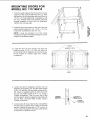
MOUNTING DOORS FOR
MODEL NO. 113.198410
1. Slide the upper support
into the top of the center
support
so the top and side holes line up. Then
assemble
to the front and rear skirts with four (4)
1/4-20 x 1/2 truss head bolts, Iockwashers,
and
hex nuts. Position
bolts from bottom
side with
threads
upwards
on front skirt as illustrated.
Tighten
hex nuts securely.
2. Assemble
the front support
to the lower and the
upper supports
with four (4) 1/4-20 x 1/2 truss
head bolts, Iockwashers,
and hex nuts.
NOTE:
It may be necessary
backwards
to tighten the bolts
support
to the lower support.
to tilt
holding
E=r
the stand
the center
t,e _
_
3. Locate the four (4) door hinges
and eight (8)
plastite
screws
10-14 x 1/2. Lay out doors on
floor side by side to establish
left and right side.
Mount
hinges
on outside
edge
with phillips
screwdriver.
HINGES
_/
MAGNETIC
CATCH
_r
DOORS
4. Locate the two (2) magnetic catches, two (2)
magnetic stop plates, four (4) pan head screws
6-19 x 1/2, and four (4) pan head screws 6-32 x
3/8. Attach a magnetic catch to each door with
two (2) pan head screws 6-19 x 1/2, using a
Phillips screwdriver. Then on each side of the
center support, attach a magnetic stop plate with
two (2) 6-32 x 3/8 pan head screws, using a
Phillips screwdriver.
O
CENTER
SUPPORT
o
MAGNETIC
STOP PLATE
_
o
"_
_
SCREW
6-32 x3/8
5. Locate eight (8) truss head bolts, Iockwashers
and hex nuts to attach
door hinges to the side
panels. Tighten
hex nuts with a 7/16" wrench or
socket. Adjust stop plate if necessary
with phillips
screwdriver
for desired closure.
23
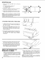
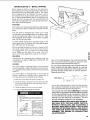
MOUNTING
1. From loose
hardware:
SAW
parts bag #488, find the following
8 - Truss Head Bolts 1/4-20 x 1/2
8 - Lockwashers External 1/4
8- Hex Nuts 1/4-20
T.uss.EAOBO,TIf
2. Place saw on cabinet so that holes in bottom
saw line up with holes in top of cabinet.
3. Install
bolts, Iockwashers,
and nuts
Tighten
securely
using a 7/16" wrench
of
as shown.
or socket.
4_"
"_"
sws'
Ill
° // °!1
HEX NUT
NOTE: It may be necessary to loosen the bolts
holding the skirt to the side panel of the cabinet if the
holes do not line up. Once mounting bolt is in place
retighten cabinet bolts securely.
ATTACHING
TRIM
CAPS
& TRIM
LEDGE
1. Locate the two (2) trim caps, the trim ledge, the
six (6) type "B" #10 x 1 screws and eight (8) type
BT 1/4 x 1/2 screws.
TRIM
LEDGE
2. Place the trim ledge against the bottom of the
base using four (4) type "B" metal screws, secure
the trim ledge to the base from below using a
phillips screwdriver.
3. Then reach through the base from behind the
front table board and secure the trim ledge with
four (4) type "BT" screws using a phillips
screwdriver.
4. Position the trim caps in place and hold in place
with type B metal screw from the bottom side.
5. Then reach through the base from behind the
front table board and secure the trim cap with
two (2) type "BT" screws using a phillips screwdriver. Repeat procedure for other side.
TRIM
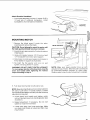
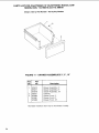
INSTALLING
DRAWERS
MODEL NO. 113.198610
FOR
1. Slide center slide brackets
so they extend about
6" beyond front of stand. Position the 10" drawer
on bottom
slides
and engage
center
slide
brackets.
Push drawer closed to engage drawer
slide catches.
2. Repeat
24
assembly
for 6 inch
CAF
and 3 inch
drawers.
3. Open each drawer to check drawer stops. If
drawer slides past stop, use a screwdriver
to
bend the stop tab further out on drawer slide.
Recheck drawer to insure drawer stop works. Do
not over bend drawer stop.
NOTE: To remove a drawer, use a screwdriver
through the side of the slide to push the drawer slide
stop tab back to free the drawer.
Attach Elevation Handwheel
1. From loose parts bag, find one (1) screw 10-32 x
1/2 and one (1) external Iockwasher.
Install
handwheel to front of base as illustrated.
ELEVATION
HANDWHEEL
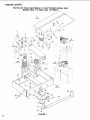
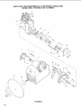
MOUNTING
1. Remove
wrenches
MOTOR
the blade
guard.
Locate
and remove the blade.
CAUTION:
13o not attempt
the blade guard and blade
the
to mount the motor
have been removed.
2. Elevatethe
arm approximately
shipping
pad.
3. Using a 3/4 socket remove
I/2" flat washer from motor
2 inches
arbor
until
to remove
1/2-13 lock nut and
pivot support.
4. Slide motor on motor pivot support
until
firmly seated on support
as illustrated.
motor
5. Re-install
the flat washer
tighten until snug with 3/4"
nut
and lock
socket.
is
and
_-
WARNING:
DO NOT OVER TIGHTEN
LOCKNUT.
To insure proper function of the bevel lock, move the
bevel lock handle while tightening
the Iocknut.
Adjust according to Step 6.
6. Push bevel
lock handlel
[
NOTE:
Make
sure bevel encoder
lines up with
actuator
on top of motor. Bevel encoder
cord should
be positioned
between
actuator
on motor
plate.
Slide encoder to top of scale if adjustment
is needed.
to left side to lock.
NOTE: Bevel lock handle should not contact extreme
left side of yoke when in locked
position.
If bevel
lock handle is permitted
to contact yoke the following
adjustment
is required.
a. Unlock
bevel lock handle
and tighten
motor
Iocknut. Recheck bevel lock handle position
(see
illustration).
b. Repeat
tighten
adjustment
if necessary.
or motor will not index.
Do
not
over
c. Locate yoke plug from loose parts bag. Make
sure bevel lock handle is locked and then snap
plug in place.
25
ALIGNMENT
PROCEDURE
IMPORTANT: In order to obtain maximum cutting
accuracy and safety, the following six steps must be
carefully followed. Become thoroughly familiar with
these steps so that you can always maintain your
saw in proper alignment. The accuracy of each
adjustment is always dependent upon the accuracy
of the preceeding adjustment.
Be sure to align the saw in the exact sequence
described to insure proper alignment and cutting
accuracy.
o
O
o
_
After following
the 6 step assembly
and alignment
procedure
and the Basic Saw operation
section refer
to Trouble
Shooting
section
if any difficulty
is
experienced
when performing
any sawing operation.
STEP
Adjusting
Column
1. Elevate
ONE
Tube in Column
and then
lower
Support
the arm.
(a) If the column
binds and elevation
is difficult,
loosen the four (4) bolts, with 9/16 socket and
extention,
located
through
the holes in the
rear column
support
cover until movement
is
smooth
but firm.
/
(b) If column
moves
front
to rear within
the
column
support,
tighten
the four (4) bolts,
with a 9/16 socket
and extension,
located
through
holes in rear column
support
cover
until movement
disappears.
Elevation
should
be smooth
and firm. Recheck
adjustments,
repeat steps (a) and (b) if necessary.
2. Locate the four (4) plastic
hole caps in loose
parts bag #532. After all adjustments
are made to
the column
support
insert the plastic caps in all
four holes in rear column
support
cover.
STEP TWO
o
NOTE: The following
adjustment,
performed
properly, will result in the work table being flat and
parallel
to the arm. This helps insure the blade will
cut the same depth along the entire crosscut
travel.
LEVELING
FRONT
WORK
@
®
@
TABLE
1. Loosen the three (3) leveling
screws located
the center of the table with a 1/8" hex'L'wrench.
2. Check the five (5) mounting
screws
they are snug. Do not over tighten.
in
®
®
to make sure
3. Push the bevel lock handle to the right to release
the motor.
Index the motor with the saw blade
end of the motor shaft down and lock bevel lock
handle to the left.
4. Slide the carriage
so the motor
center of front table board.
5. Unlock
position
left.
the miter
as shown,
lock handle
and position
shaft
MITER
LOCK
HANDLE
is in the
in the unindex
the arm to the
/ I
26
o
-lb -Ib
6. Lay the arbor wrench on the work tableunderthe
motor shaft. Carefully lower the arm with the
elevation handle until the motor shaft is just
touching the arbor wrench. The wrench should
slide back and forth with only slight contact with
motor shaft.
NOTE: When moving the arm from the left side to the
right it is necessary to move the motor along the arm
to check the front table at several points from front to
back.
7. Starting from the left side of the front table board,
move the Radial Arm to the right checking
the table with the arbor wrench to determine the
lowest spot in the table. Once the lowest spot in
the table is determined, you can begin to level the
table.
RADIAL ARM
--_E
/%
E==
ooi=I:
/
NOTE: For safety reasons, stops have been
to prevent 360 ° rotation
of the radial arm.
provided
8. Position the arm over the lowest spot in the table
and repeat Step 6.
€
-
45° LEFT_""_7
REAR
TABLE
BOARD
_
T
_
9. Tighten the mounting
screws located at the high
spots in the table with a Phillips
screwdriver.
Then recheck the entire table. Make sure center
leveling hex screws are loose.
NOTE: Do not change this elevation
entire work table has been adjusted.
setting
until the
10. Lay the rear table board on edge across the front
table to serve as a straightedge
to determine
whether the front table board is high or low at its
center.
11. If the front table is high at center, first tighten the
center hold down screw until table is level - then
tighten the three (3) leveling screws until those
screws are tight. If table is low at center, first
loosen the center holddown screw, then tighten
the three (3) leveling screws until table is level.
Retighten the center holddown screw. Recheck
table to make sure it is level.
12. Position the rip (guide) fence, spacer board and
rear table board behind the front table board, and
push front table lock handles down as shown.
13. Return
motor
to vertical
position.
27
Adjusting front table lock handles
WARNING:
TO
BREAKAGE, OR
TABLE BOARD
TABLE BOARDS
PLACE.
AVOID SUDDEN
SLIPPAGE,
THROWING OF PARTS, FRONT
LOCK HANDLE
MUST LOCK
AND RIP FENCE SECURELY IN
1. To adjust the table board clamps check by
pulling up on rip fence. There should be enough
pressure to keep the rip fence from pulling up. To
adjust the pressure on the clamp:
a. Lift front
table lock
pressure
on boards.
handles
b. Loosen
the two eccentric
located
at the rear of the
7/16" wrench
or socket.
up
to
release
spacer
clamps
table top with a
c. Rotate the spacer toward the rear table board.
Tighten
spacer with 7/16" wrench
or socket.
Repeat procedure
for clamp on other side.
/
d. Push down on front lock handles and recheck
pressure
by pulling up on rip fence. If rip fence
is too loose, repeat adjustment.
STEP THREE
Squaring Crosscut Travel
NOTE: This adjustment
helps ensure the blade
accurately travels square to the rip fence.
1. Index arm at 0° miter and lock.
SHAFT
2. Install saw blade as shown. Motor shaft has left
handed threads - turn nut counterclockwise
to
tighten.
CAUTION: Do not overtighten arbor nut. Use arbor
wrench to "snug" nut in place. Overtightening could
distort the blade collars and cause blade to wobble.
3. Lower arm until saw blade just clears the front
table. Be sure the miter lock handle and the bevel
lock handle are locked.
\
4. Placea framing square on the table as shown and
position the blade and square until the leg of the
square just contacts a tooth of the blade. Mark
this tooth with a pencil.
NOTE: The framing (or combination)
square must
be "true" - see start of "Assembly and Alignment"
section on page 10 for checking method.
5. When the carriage is moved back and forth on
the arm, the marked tooth should just touch the
square at all points. If marked tooth moves into
square or away from square the following adjustments are required.
(a) Loosen the four (4) 1/4-20 socket set screws
on both sides of the front column support (2
on each side) with a 1/8" Hex "L" wrench as
illustrated on next page.
(b)
28
Move the arm in the proper direction
to make
marked tooth follow edge of square when the
saw blade is moved along arm in a "crosscut"
manner.
BEVEL LOCK
HANDLE
MARKED
TOOTH
MITER LOCK
HANDLE
(c) Carefully retighten uppertwo (2) 1/4-20 socket
set screws alternating from left side to right
side so as not to force arm out of adjustment.
FOUR
HEAD
(d) Recheck blade travel. Adjust arm position as
needed by readjusting upper screws only.
SOCKET
SCREWS
(e) Once arm position is good, tighten lower 1/420 socket set screws. Do not overtighten.
Check elevating handwheel for ease of rotation. If rotating handwheel is difficult,
readjust socket set screw tightness as needed.
NOTE: The life of your saw table will be lengthened
considerably if you will cover the front table with a
fitted piece of 1/4 inch plywood. This should be
tacked in place for easy replacement. Use of such a
cover will allow you to do all cutting into the cover,
rather than your table top. This will help prevent
dulling of the saw blade and striking table mounting
hardware. Place tacks out of the path of the saw
blade.
,=8:
STEP FOUR
Squaring Saw Blade to (Work) Table
NOTE: If alignment procedure step two was not
performed, this adjustment cannot be accomplished.
1. Place a framing square on the table with the short
leg against the saw blade. Do not allow the
square to rest against a "set-out" tooth; it must
rest flat against the blade side.
2. If the square does not touch the saw blade as
shown (with square held firm against table top)
the following adjustments are required.
(a) Tighten
rip lock handle.
(b) Unlock
motor.
bevel lock handle.
SQUARE
\
II1
Do not un-index
BEVEL
RIP F:ENCE
HAND_
(c) Loosen the four (4) socket set screws located
behind yoke as illustrated with a 1/8" Hex "L"
wrench. Rotate motor while holding square
firmly against saw blade and table top until
the square touches the sawblade as shown.
(d)
Lock bevel lock handle. Recheck alignment
to
make sure blade did not move when bevel
lock handle was locked.
(e) Tighten the four socket set screws. Unlock
bevel lock handle, unindex the motor, reindex
and relock the bevel lock handle. Recheck
alignment
again. If blade is not square to
table, return to step (c) and repeat.
(f) To assure the blade is square to the table,
elevate the arm enough to bevel the motor to
45 ° stop. Then return to 0 ° position, lower the
arm and lock bevel lock handle. Recheck
alignment.
I
t_J
_
_
WRONG
FOUR
HEAD
SOCKET
SCREWS
WRONG
SQUARE
I
TABLE
I
SQUARE
TABLE
RIGHT
MOTOR
SQUARE
TABLE
29
STEP
Squaring
Blade
FIVE
to Rip Fence
NOTE: If alignment
procedure
steps three and four
were not performed,
this adjustment
step cannot be
accomplished.
This adjustment
helps avoid binding
(kickbacks)
or splintering
of wood surface, or burning of the kerf.
1. Position
carriage
as shown and tighten
rip lock
handle.
Place a framing
square against
the rip
fence and the saw blade, as shown. The long leg
of the square must be held firmly against both the
fence and the table top, and the short leg must
not touch any of the "out-set"
teeth on the saw
blade. Check at several points of blade rotation.
\
FRAMING
SQUARE
2. If the square does not touch the blade at both of
the two points as shown, a heel condition
exists.
3. To correct
"heel"
condition,
(a) Unlock
swivel
lock
proceed
as follows:
handle.
NOTE:
(b) Using a 1/8" Hex "L" wrench
loosen the four
socket
set screws
located
through
access
holes on bottom side of yoke as illustrated.
(c) Rotate the yoke assembly
properly.
(d)
until blade is aligned
Lock swivel lock handleand
retighten
the four
(4) socket set screws. Recheck for heel. If heel
condition
exists, return to step (b) and repeat.
NOTE: This alignment
set both yoke indexing
rip
procedure
positions
FENCE
will simultaneously
for blade in and out
FENCE
FENCE
]
1"
-SO'UARE
....
._
h-SQUARE-----,i_
L
SQUARE
/ _R
IG_T
L_
WRONG
/
This adjustment
helps avoid the grabbing
of the wood during edging operations.
or throwing
1. With sawblade
in 90 ° crosscut
position,
elevate
saw, then rotate motor
to its vertical
position
(blade
parallel
to table top). Lock bevel lock
handle
and be sure swivel
lock handle
is in
locked position.
2. Check blade for bevel heel by positioning
square
perpendicular
to fence and between
blade and
table as shown.
Lower arm until face of blade
rests on square. Be sure square
of blade and not on a "set-out"
result in a false measurement.
MO_TOR
L_
Bevel Heel Adjustment
is resting on face
tooth as this will
3. If there is a visible gap between saw blade face
and the edge of the square, a bevel heel condition
exists and the following
adjustment
is necessary.
It may be necessary
to use
pliers to grip the short end of the
Hex "L" wrench to loosen or tighten
the socket
cap screws. Remember
to wear eye protection
when performing
this procedure.
a.
b,
Unlock the bevel lock handle and loosen the
two cap screws located thru the rear of the
motor support (see illustration). A 1/8" hex "L"
wrench is needed to loosen these screws.
Lift or lower the rear of the motor support
the gap between
the blade and square
appears. Lock the bevel lock handles.
until
dis-
_YOKE
c. Tighten the two cap screws and recheck
alignment between the face of the blade and
the square. If a gap condition exists, repeat the
above adjustment.
MOTOR
SUPPORT
_AP SCREWS
d. From loose parts bag #532 find the motor
support cap and install into rear of motor
support.
E==
SQUARE
NOTE: It may be necessary to use
pliers to grip the short end of the
Hex "L" wrench to loosen or tighten
the socket cap screws. Remember
to wear eye protection when performing this procedure.
/
RIGHT
WRONG
WRONG
TABLE
STEP
SIX
Installing Blade Guard and Adjusting Anti-Kickback
Pawls and Spreader
1. Install
blade
guard
GUARD-_-_-_-
i
on motor.
2. Unlock
the swivel lock handle
blade into the IN-RIP
position.
lock handle.
and
Lock
rotate
the
the swivel
ANTIKICKBACK
PAWLS
J_
3. Position blade against fence and lock the rip lock
handle. Loosen wing screw and lower the antikickback
bar assembly
until side of the spreader
is flush against the fence and the anti-kickback
pawl is resting on top of the fence (as illustrated).
SPREADER
FENCE
\_
NOTE: If the spreader
is not flush against the fence
or will not easily clear the top of the fence when
lowered,
the following
adjustment
is required.
TABLE
it'
/
/
a. Loosen the two hex nuts, one on each side of
the spreader with 1/2" open end wrench.
b. Slide the spreader with fingers until the side of
the spreader
rests flush with the rip fence.
c. Snug
both nuts
recheck alignment.
against
the
spreader
and
ANTIKICKBACK/SPREADER
WING SCREW
d. If spreader aligns with fence and blade, tighten
with wrench and raise anti-kickback
spreader
up to guard and retighten
wing screw.
4. Release rip lock
fence and rotate
5. From
guard
loose parts
rear bumper
handle, move blade
to crosscut
position.
bag #532, locate
pad and install.
away
from
the
blade
\,
BUMPER
TAB
/
PAD
FENCE
\
_
ANTIKICKBACK
ANTIKICKBACK
BAR
PAWLS
31
location and function of the electronic indicator system
BATTERY STORAGE
COMPARTMENT
(ON SIDE)
FUNCTION
ON/OFF
ELECTRONIC
MEASUREMENT
Digital
Readout
LOCK
REMOVE
YELLOW
KEY
BEVEL ANGLE
FUNCTION
KEY
MITER
FUNCTION
KEY
RIP POSITION
FUNCTION
BLADE ELEVATION
FUNCTION
KEY
REFERENCE
SET KEY
KEY
ANGLE
DIGITAL
TO
INDICATORS
READOUT
DISPLAY
KEY
Display
The liquid crystal display (LCD) on this saw gives
the user the ability to accurately
position
the saw
blade and make precision
adjustments
to the blade
position.
The four functions
displayed
on the saw
are:
Rip position
- displays
the distance
the blade is from
the rip fence when the unit is in the in-rip or out-rip
position.
Zero is normally
set with the blade contacting the front face of the rip fence.
Bevel
blade
blade
A digital readout display shows the
of the blade in decimals.
If you need
numbers
to fraction
values, there
chart provided
on page 35 of this
reference.
angle - displays
the bevel angle
has been set. Zero is normally
in the vertical.
at which
set with
the
the
Elevation
- displays
the vertical height of the blade
above the table top. Zero is normally
set with the tips
of the blade teeth touching
the table top.
Miler angle - displays
the miter angle at which the
blade has been set. Zero is normally
set with the
blade in the cross-cut
position
square
to the rip
fence.
Function
Keys
The six keys located to the right of the display screen
are the function
keys. They are used to select the
indicator
that is to be displayed
or adjusted to set the
indicator
value to zero, orto turn the display "On" or
"Off".
Key -- Turns
the display
"On"
or "Off".
The display
also shows
which
displayed,
either BEV, ELE, MIT,
minus sign will display
when the
negative
(less than the "Zero" set
elevation
or miter.
function
is being
RIP, or O-RIP. A
numeric
value is
position)
in bevel,
NOTE:
In order to extend the battery
life, the LC
display
on this unit automatically
shuts "Off" after
approximately
three (3) minutes
if no movement
of
Bevel, Miter, Rip, or Elevation
have occurred.
The
display
will return showing
the correct
readout
by
pressing
_
yoke
assembly
"off"
can
. Any rapid
when
result
in
movement
the digital
[
bevel angle
Key -- Selects
elevation
Key -- Sets or re-sets
to zero.
Key -- Selects
32
miter
(BEV)
(ELE)
display.
the selected
angle
(MIT)
Key -- Selects in-rip or out-rip
(RIP or O-RIP) display.
display
readout
function
display.
display
is turned "on". If this occurs,
to reset the reference
positions.
Battery
of the motor
EE.EEJ
/
Key -- Selects
present position
to convert these
is a conversion
manual for your
display
when
is
the
I
it is necessary
Compartment
The LC display and indicator
system is powered
by a
6 volt, size J, alkaline battery. The battery is installed
in the battery compartment
located on the left side
wall of the indicator
display casing. Once the battery
has been correctly
installed,
the electronic
indicator
system will continuously
monitor
and store the saw
blade position
information
whether
the display
is
"On" or "Off".
1. Installing the Battery
Install the battery into the compartment
as shown.
The bottom rear tab of the battery should be held
inside the compartment by the bottom wall of the
casing.
BATTERY
The indicator
display should appear within a
second or two after the battery is correctly
installed. If the display remains blank, remove
and reinstall the battery. If the display still remains
blank, refer to the trouble shooting guide in this
manual.
Once the display
is activated,
install
compartment
cover.
Turn
off the
pressing the o_,_o_ key.
the battery
display
by
L_
To remove the battery compartment
cover use a
small screwdriver.
Insert screwdriver
between
cover and arm prying
up at the middle
of the
cover. To remove battery, push in on upper edge
of battery to disengage
tab.
t,-O
,..J
Checking
and Setting
the Angle
Encoders
In order to obtain accurate readings when performing
bevel and miter cuts, it is necessary
to align the
electronic
encoders
which sense the blade angle
position.
The following
procedures
should
be followed to properly
make these adjustments.
Aligning
the Miter Angle
1. Turn the electronic
[o,toF_ key.
2. Pr'es-sthe
Encoder
display
on by pressing
the
_MITE"It key.
3. Ensure that the arm is at the 90 ° crosscut
index
position
and that the miter lock handle is in the
_ock position.
4. Press
be:
the
,EFSCT key.
.0] (Refer
I'"
Shooting
section
not as illustrated.)
The
displayshould
to Trouble
if the display
is
i
5. Rotate the arm to the right side 45 ° miter index
position.
Lock arm in this index position.
Display
should read " 45.0".
6. Rotate
the arm
to the left side
position.
Lock arm in this index
should read "-45.0".
45 ° miter
position.
o__
@o
index
Display
7. If the display does not read correctly
at either or
both of the right and left index positions,
adjustment of the miter encoder
is required
using the
following
procedure.
a Remove the arm rear cover
two mounting
screws.
b. Index
the arm to the 45 ° right
c. The miter angle
rear of the arm,
encoder
mounted
by removing
miter
the
position.
is located
inside the
on the column
tube
directly
below
illustration).
the
miter
locking
clamp
(see
33"
Loosen the miter angle encoder mounting
bracket by backing the mounting screws off
until the encoder will rotate slightly on the
column tube.
d.
e. Rotate the encoder on the tube by tapping the
encoder lightly until the display reads "45.0".
Do not force or hit the encoder to make this
adjustment.
LINE UP
WITH HOLE
f. Re-tighten the encoder mounting screws and
re-check the encoder display using steps 1
through 6 above.
g. If the adjustment will not align the display
readings to the miter index positions, refer to
the trouble shooting guide in this manual.
h. When the encoder alignment has been completed, reinstall the arm rear cover to the arm.
Aligning the Bevel Angle Encoder
1. Turn
the
the
electronic
_
2. Press
"On"
by
pressing
key.
[BEVELkey.
the
3. Ensure
position
handle
that the motor is at the 0° bevel index
(blade vertical)
and that the bevel lock
is in the locked position.
4. Pressthe
play
display
_iR_FSET!_
key. Thedis-
should
be:
.Ev
.0
(Refer to the Trouble
Shooting
section
of the manual if the display is not as illustrated.)
5. Unlock the motor by pushing the bevel lock knob
to the far right. Rotate the motor to the 45 ° bevel
index position
and lock. Display should now read
"45.0".
ALIGNING
MOTOR
SCREWS
SUPPORT
BEVEL
ENCODER
SCALE
a. Unlock
the motor and rotate the motor to the
90 ° bevel index position
and lock. Display
should now read "90.00".
6. If the display does not read correctly,
adjustment
of the bevel angle encoder is required.
Follow the
procedure
outlined
to correct
this alignment.
a. Set the motor to the 45 ° bevel index position.
Be sure that the bevel lock handle is in locked
position.
b. The bevel angle encoder
is located
between
the motor support
and the yoke casting.
(See
Ilustration)
c. Loosen
the bevel angle
encoder
aligning
screws slightly,
until the bevel encoder
reader
will slide along the scale.
d. Move
reads
make
the encoder
reader until
the display
"45.0". Do not force or hit the encoder to
this adjustment.
e. Retighten
the encoder
aligning
screws
and
recheck
the encoder
display
using steps 1
through
5.a. above.
NOTE:
It may be necessary
through
"e" more than once
adjustments.
34
to repeat
steps "a"
when making
small
YOKE
CASTING
Pressthe key.
Presstose, thezero
f. If the adjustment will not align the display
readout to the bevel index positions, refer to
the trouble shooting guide in this manual
reference
readout.
This
g. When the encoder alignment has been completed, the electronic indicator system should
be ready for use.
Using the Electronic Indicator System
1. Setting the indicator
reference points.
the display
"On"
tho
by pressing
bevel displav
readout. should
This
read:
reference
Press the [_'TER]I key. Press
_
zero reference
angle for the miter
should
read:
to set
readout.
_,T
display
the
[,,,
is displayed,
should
to set the
The indicator
.00!
press
_]
again.
_
key to set
for the blade in-rip
now
_
display
elevation
.00 !
read:
should
[_,sET! , the display
read: I",_
the zero
location
.00]
key
again.
should
now
appear.
Press
read:
[o-,,,
.00
should
The
"O-Rip"
To set out-rip reference
point, swivel theyoketo
the out-rip
position.
Move rip fence to rear
position
and measure 10 inches from rip fence's
front side.
NOTE: The saw will be very close to this point. The
radial arm rear travel stop will not allow the blade
any closer to fence than approximately
10 inches. To
accurately
set the reference,
measure
with tape
measure or ruler to determine
exactly !0 inches from
fence to the blade.
.0 1
BEy
[EL_
display
indicator
for the
blade
key. Press
[_
location
for in-riD.
Press
key.
angle
read:
the
Press
_
zero reference
The
a, ,efooo,,oo
ke . ress
to set the zero
This display
_
should
Before
pressing
reference
location
readout.
Place the blade
or cutting
tool in the exact
position
and angle that you have selected
as the
zero reference
position.
Turn
for
display
If "O-Rip"
In order to establish the starting location
point of
the blade, it is necessary
to set the indicator
references
at zero. Normally,
these zero references are the front of the fence, the top of the
table, and with the face of the blade square to
both of these surfaces.
However,
many instances
will require selection
of the reference
points to fit
the woodworking
operations
to be performed.
location
the
.0]
When
blade
key once
reference
is 10 inches
from
to zero and then
point. The display
fence,
push
--_
_
a second
time to set
should read [o-,,p
I0.00]
.06
.09
.03
.12
FENCE
_
.19
.16
.22
.25
DECIMAL
NOTE:
EQUIVALENTS
All
to
the
decimals
nearest
are
rounded
.01
inch.
35
location and function
WARNING: FOR YOUR OWN SAFETY ALWAYS
LOCK THE SWITCH "OFF" WHEN SAW IS NOT IN
USE. REMOVE KEY AND KEEP IT IN A SAFE
PLACE . . . ALSO IN THE EVENT OF A POWER
FAILURE, TURN SWITCH OFF. LOCK IT AND
REMOVE THE KEY. THIS WILL PREVENT THE
SAW FROM STARTING UP AGAIN WHEN THE
POWER COMES BACK ON.
DIGITAL
of controls
WARNING: THE SAWBLADE, DADO, OR CUTTING
TOOL MUST BE REMOVED FROM THE SAW
ARBOR BEFORE USING THE ACCESSORY SHAFT,
NEVER OPERATE THE SAW WITH CUTTING
TOOLS (INCLUDING
SANDING ACCESSORIES)
INSTALLED ON BOTH ENDS OF THE SAW ARBOR.
MAKE SURE THE UNUSED ARBOR IS ALWAYS
COVERED BY A GUARD, A CAP, OR THE ARM.
READOUT
RIP LOCK
ON-OFF
BLADE
GUARD
YOKE
HANDLE
MITER
LOCK
HANDLE
AKB/SPREADER
WlNG SCREW
GUARD
CLAMP
SCREW
\
TABLELOCK
HANDLES
_T ACTUATOR
36
HANDLE
SWITCH
SWIVEL
LOCK
HANDLE
Depth of Cut (Elevation)
a. The diagram shows the elevation crank which
is used to raise and lower the saw blade.
b. Clockwise
rotation
raises the blade . . .
counterclockwise
rotation
lowers it. One
complete turn of the handle will raise or lower
the saw blade 1/16 inch.
c. Handle can be folded
in when not in use.
2. Angle of Cut (Miter)
Proper Indexing Method woodworking
equipment
Radial Saw, acquire the
direction only, whenever
preparation for a different
Experienced operators of
such as this Craftsman
habit of indexing in one
a new setting is made in
operation.
Example: When moving the arm to a miter index
position move it slightly past the desired index
position, then return to the index position carefully
to index and lock. Yoke indexing and bevel indexing
can be accomplished
in a similar manner. This
indexing technique tends to neutralize any stresses
impaired upon saw components and contributes to
the high degree of accuracy the saw is capable of
producing when operated expertly.
MITER
2
LOCK
\
...J
a. The miter lock handle locks, unlocks and
indexes the arm for left and right miter cuts.
NOTE: For safety reasons stops have been provided
to prevent 360 ° rotation of the radial arm.
b. The radial arm has positive index positions
at
0 ° and 45 ° left and right. The arm is rotated by
pulling the miter lock handle from left to right
and releasing
the index pin. Move the arm to
the desired
miter angle and push the miter
lock handle back to the lock position.
,
SWIVEL
LOCK
HANDLE
Yoke Swivel (Ripping)
a. Swivel lock handle is to lock, unlock and index
the yoke swivel adjustment.
b. The yoke swivel index pin automatically
indexes the yoke at 90 ° position. Pull the
swivel lock handle forward to unlock the yoke,
continue to pull this handle until the index pin
is released.
C.
The swivel lock handle locks the yoke to the
carriage in any position. Pull the handle forward to release the yoke; push the handle
rearward to secure the yoke.
4
4. Rip Position Lock
a. The rip lock handle is pushed rearward to lock
the carriage on the radial arm and pulled
forward to release it.
b.
When performing
crosscutting
operations,
the
rip lock handle must be released so the carriage
is free to travel along the arm. The lock handle
should be tightened
until the operator
is ready
to grasp the yoke handle and make a cut.
37
5. Blade Angle (Bevel)
a. A single bevel lock handle is used in angular
positioning
and indexing of the motor, to
provide the desired saw blade (bevel) angle.
5
b. The bevel lock handle controls the angular
position of the motor with respect to horizontal.
C.
d°
The bevel lock handle automatically
indexes
the motor at 0 °, 45 ° and 90 ° . Slide the bevel
lock handle to the far right while positioning
the blade, then release it. At any other position
it does not engage.
The bevel lock handle also locks the motor to
the yoke when the motor is in any position.
Pull lever to right to release and push to left to
lock.
c. Push
6. Power Switch and Key
a. To turn switch on, insert key into switch lock.
lever in to turn switch
I \\
\\
'\
off.
\
\
\
b. To turn switch on, insert finger
switch lever and pull end out.
under
•
end of
d. WARNING:
THIS LOCKING
FEATURE IS
PROVIDED TO HELP PREVENT UNAUTHORIZED USE OFYOUR SAW. ALWAYS REMOVE
THE KEY AND KEEP IT IN A SAFE PLACE.
TO REMOVE KEY, HOLD THUMB ON END
OF LEVER TO KEEP SWITCH
IN "OFF"
POSITION AND PULL KEY STRAIGHT OUT.
\
\
7. Accessory
Shaft
Use only the following
recommended
sories:
Drill chuck,
Sanding
drum, and
adapter.
accesRouter
CAUTION:
The sawblade,
dado, or cutting tool
must be removed
from the saw arbor
before
using the accessory
shaft, NEVER operate
the
saw with cutting tools (including
sanding accessories) installed
on both ends of the saw arbor.
38
ACCESSORY
SHAFT
8. Blade Guard and Anti-Kickback/Spreader
Assembly- Positioningfor Ripping.
WARNING:NEVERPOSITIONTHE GUARDOR
ANTI-KICKBACK/SPREADER
ASSEMBLYWITH
THESAWRUNNING.
NEVERPOSITIONTHEANTIKICKBACK/SPREADER
ASSEMBLY
BYGRASPING
8
GUARD
CLAMP
SCREW
THE PAWLS OR SPREADER.
TO MAINTAIN
SPREADER ALIGNMENT, USE THE TAB LOCATED
ON THE ANTI-KICKBACK
BAR.
WORK
a. The blade guard is positioned
by loosening
the guard clamp screw and rotating
the guard
so that the "nose" just clears the workpiece
as
shown.
PIECE
M,,,MUM
-{
zt
INFEED
DIRECTION
OUTFEED
SIDE
I_
NOSE OF
GUARD
This adjustment is necessary to:
1) Protect the operator from accidentally contacting the sawblade from the "infeed"
direction.
ANTIKICKBACKiSPR
WING
SCREW
2) Prevent the workpiece from being lifted
from the table by the sawblade thus minimizing lifting or fluttering (particularly with
thin and/or light workpieces).
3) Minimizesawdust
the operator.
b.
GUARD
CLAMP
SCREW
/
/
.m"_
from being thrown toward
The anti-kickback
and spreader
assembly
adjustable
to accommodate
the thickness
the board being ripped.
Make sure by trial - without
saw running
before starting
the cut that the anti-kickback
pawls will stop a kickback
once it nas started.
Insert workpiece
alongside
spreader
under
outer set of pawls by approaching
pawls in the
feed direction.
Push workpiece
sharply
in the
direction
of a kickback
(opposite
direction
of
feed). Readjust
pawls if they do not stop the
kickback
motion by biting into the workpiece.
If the workpiece
does not feed smoothly
under
the pawls, the spreader
may be set too deeply.
Loosen
the wing screw,
raise the spreader
slightly,
retighten
the screw,
recheck
workpiece in-feed and kickback
pawl function.
when
properly
made
will:
1 ) Reduce possibility of kickbacks by preventing the kerf from closing
on the sawblade.
2) Prevent "wrong-way
feed".
"Wrong-way
feed" is feeding the workpiece
- when the
sawblade
is in a rip position
- into the out
feed side of the cutting
tool (sawblade,
dado, molding
head, etc.), the side containing the anti-kickback
pawls/spreader.
This
can be extremely
hazardous
because
the
sawblade may grab the workpiece
and throw
=.
is
of
For ripping,
the anti-kickback
and spreader
assembly
is positioned
by loosening
the wing
screw and, with the tab provided,
positioning
the anti-kickback
and spreader assembly
until
the pawls assume approximately
the position
shown. Tighten
the wing screw.
These adjustments
EADER
SPREADER
ANTIKICKBACK
/
/
PAWL
D,.EC ,O.
OF
FEED
DIRECTION
OF
ANTIKICKBACK
KICKBACK
PAWL
POSITION
it violently
toward
the nose of the guard
(infeed
side of the tool)
possibly
pulling
your hand with it before you can react. See
Danger
label on outfeed side of the guard
just below the dust elbow.
"Wrong-way
feed" differs from kickback". A
"kickback"
is generated
by the sides (one or
both)
of the teeth,
because
of binding
between
the fence (heel), pinching
of the
sides
of the sawbtade
(failure
to use
spreader),
a dull blade, and/or
inadequate
set of teeth of sawblade.
3) Act as a partial guard regarding accidental
contact
with the sawblade
side when
at the outfeed
ripping.
For crosscutting
the anti-kickback
and spreader
assembly
is positioned
by loosening
wing screw.
With the tab provided
position
the anti-kickback
spreaders
assembly
until the pawls just clear the
workpiece
or fence which ever is higher.
39
basic saw operation
WARNING: TO AVOID MISTAKES THAT COULD
CAUSE SERIOUS PERMANENT INJURY, OBSERVE
ALL THE FOLLOWING INSTRUCTIONS
IN ADDITION TO THOSE ON PAGES 2-6.
Basic saw operations are summarized in six categories, explained and illustrated in the following
paragraphs.
NOTE: Refer to paragraphs under "Location
and
Function of Controls" for illustrations and description of controls. Page 36.
CUTTING
A KERF IN THE WORK TABLE
AND FENCE
NOTE: The life of your saw table will be lengthened
considerably
if you will cover the front table with a
fitted
piece of 1/4 inch plywood.
This should
be
tacked in place for easy replacement.
Use of such a
cover will allow you to do all cutting
into the cover,
rather than your table top. This will help prevent
dulling of the saw blade and striking table mounting
hardware.
Place tacks out of the path of the sawblade.
1. Elevate arm so that the blade
fence
and then push the
rearward
position.
clears
motor
the top of the
to its most
2. Lower the arm so that the blade just clears the
rear table. Note: The rear table should be at the
same level as the front table (see "Leveling
Front
Work Table".
page 26). If front table cover is
used, set blade so that it just clears the front table
board cover.
3. Lock the rip lock handle and check to make sure
carriage
is locked
in place.
Plug saw into a
grounded
outlet.
(See section
titled, "Electrical
Connections",
page 7.)
4. Insert
the yellow
key into switch
and, while
holding
the yoke handle, turn the switch on.
5. With the motor
on, turn the elevation
handle
counterclockwise
to lower the sawblade
to where
it just cuts into the table approximately
1/32 to
1/16 inch deep. While holding
the yoke handle
and with motor still on, unlock the rip lock handle
and then pull the motor forward
and out to the
front stop on the arm. This will allow the blade to
cut through
the fence and to curashallow
kerf in
the table 1/32 to 1/16 inch deep to provide for the
blade cutting completely
through the workpiece.
NOTE: A kerf will have to be cut into the table prior to
making any thru cutting operation using this procedure.
REQUIREMENTS
TYPE OPERATIONS
(Operations
1 through
FOR
CROSSCUTTING
4)
Always
position
the workpiece
firmly
against
rip
fence (guide) and lay it flat on work table surface.
48
NOTE:
To maintain
table
strength,
workpiece
stability,
control
forward
motor
of carriage,
and
avoid accidents,
always:
1. Use only blades
undamaged.
that are sharp,
correctly
set and
2. Make sure the arbor nut is snug.
3. Clamp
the guard
in a horizontal
4. Lock the swivel lock handle.
locked. (See page 37.)
position.
Make sure it is firmly
5. Hold work firmly
against
table and fence.
To
avoid tipping
or throwing
of workpieces
thicker
than the fence is high, install a higher fence (at
least workpiece
thickness).
Always
place the
fence in the most forward
position
(farthest
from
the column
support)
compatible
with the workpiece being processed
and the operation
being
performed.
With the carriage
fully retracted,
the
blade
must not contact
the workpiece
when
placed against the fence, within the stated capacities of your saw. Do not confine the cutoff piece
with your hand, length stop or any other item.
The blade could throw it, causing
an accident.
(SEE
ITEM
"10"
AT
LEFT)
6. Keep hands well away from saw blade. Do not
place hands where sudden blade or workpiece
movement could cause hand to slip into the path
of the blade. Always keep the hand holding the
workpiece visible at all times.
7. Lock the bevel lock handle. Make sure it si firmly
locked. (See page 38.)
8. Adjust the elevation so blade will cut into the
table cover or table not more than 1/32 inch.
9. To adjust the anti-kickback
and spreader
bly so the pawls just clear the workpiece
fence. (See page 39.)
assemand the
10. Pull saw forward just enough to cut the lumber in
two, and then return
the saw to its full rear
position.
It is dangerous
to pull blade too far out
beyond the piece being cut. When it is returned
it
can pick up the board and throw it over the fence.
OPERATION
f,D
IMPROPER
(SEE ITEM
"10"
AT
LEFT)
NO. 1 - CROSSCUT
Crosscutting
is the process
of sawing
across the
width
of the workpiece
by pulling
the saw blade
through
it and using the fence as a support
for the
edge of the workpiece.
Never crosscut
free-hand.
WARNING:
YOU WILL NOTICE THAT WHEN PULLING THE SAW BLADE
TOWARD
YOU DURING
CROSSCUTTING
THE BLADE
TENDS
TO FEED
ITSELF
THROUGH
THE WORKPIEOE.
THIS
IS
DUE TO THE ROTATION
OF THE BLADE.
TO
CONTROL
THIS YOU SHOULD
DEVELOP
THE
HABIT HOLDING
YOUR RIGHT FOREARM
IN LINE
WITH THE ARM OF THE SAW THROUGHOUT
THE
CUT. ALSO MAKE SURE THE CARRIAGE
BEARINGS ARE ADJUSTED
PROPERLY
SO CARRIAGE
DOESN'T TRAVEL TOO FREELY.
OPERATION
NO. 2 - MITER
CROSSCUT
Miter crosscutting
is the process of sawing across
t_e width of a workpiece
at any angle other than a
90 ° (square)
cut. The 45 ° miter angle is a popular
one, since two boards cut to 45 ° can be assembled
to form a 90 ° corner
for producing
a square
or
41
rectangular frame. The radial arm is set to a desired
angle of cut, swivel and bevel settings at 0 ° and
locked. The workpiece being cut is positioned and
held firmly against the fence and the carriage pulled
forward along the radial arm just far enough to
complete the cut. Carriage should then be returned
to the full rear position and locked. Allow the saw
blade to come to a stop before removing the workpiece from the saw table.
OPERATION
NO.
3 - BEVEL
CROSSCUT
Bevel crosscutting
is the process of sawing
at 90 °
(square)
across the width of a workpiece
with the
saw blade set to an angle other than 90 ° to the table.
The radial
arm and yoke are indexed
at 0 ° and
locked
securely
in place. The bevel is set to the
desired
angle of cut and locked.
The workpiece
being cut is positioned
and held firmly against the
fence and the carriage
is pulled forward
along the
radial arm just far enough
to complete
the cut. The
carriage
should
then be returned
to the full rear
position
and locked. Allow the saw blade to come to
a stop before removing
the workpieces
from the saw
table.
OPERATION
NO. 4 COMPOUND
CROSSCUT
Compound
crosscut
is the combination
of miter and
bevel crosscut.
The radial arm and the angle of the
blade are set to produce
the desired cut - the yoke is
indexed
at 0 ° and locked. The workpiece
is positioned
and held firmly
against
the fence and the
carriage
is pulled forward
along the radial arm just
far enough
to complete
the cut. The carriage
should
then be returned
to the full rear position
and locked.
Allow the blade to come to a stop before removing
the workpieces
from the saw table.
REQUIREMENT
WHEN
RIPPING
(Operations 5 and 6)
WARNING: TO AVOID MISTAKES THAT COULD
CAUSE SERIOUS PERMANENT INJURY, OBSERVE
ALL THE FOLLOWING INSTRUCTIONS
IN ADDITION TO THOSE ON PAGES 43, 44 and 45.
1. Make sure that the blade is sharp, correctly
and undamaged.
set
2. Lock the rip lock handle.
3. Lock the radial arm at the 0 ° position.
4. Make sure the workpiece is kept in firm contact
with the fence and the table. The edge of the
42
board against the fence must be straight
and will
not catch on kerfs in the fencefor workpieces
thicker
than the fence is high, install
a higher
fence (at least the thickness
of the workpiece).
N EVER RIP "FR EEHAN D" (without
aid of fence).
5. Properly
set the anti-kickback
and spreader
assembly. Observe INSTRUCTIONS
in paragraph
"Positioning
guard
and
anti-kickback
and
spreader
assembly
for ripping"
under "Location
and Function
of Controls"
page 39.
6. Never rip pieces
blade.
shorter
than
the diameter
of the
SLIGHTLY
THICKNESS
3/4
7. When ripping narrow stock (less than 6 inches
but more than 2 inches between the guard and
the fence (guide) use a "PUSH STICK" (as
shown) so the workpiece is clear of the blade
before your hand reaches the guard. The end of
the workpiece to which the push stick or push
block (see below) is applied must be square to
the fence and table.
UP TO 3/8" ---
PUSH
NOTE:
LESS THAN
OF WORKPIECE
STICK
All dimensions
in inches.
8. When ripping stock 3/8" to 2" or less between the
guard and fence (guide) use an auxiliary fence
and push block. Make these work helpers to the
dimension shown.
2" OR LESS
a. Make the auxiliary fence using a piece of 3/8"
and 3/4" plywood. Fasten together with glue
and nails.
O
OO Q._
3/4" PLYWOOD
THIS FACE AND THIS
EDGE MUST
BE PARALLEL
PUSH
3/8"
PLYWOOD
b. Make the push block using
3/4" plywood.
a piece
THESE
EDGES
MUST
BE PARALLEL
3/4"
of 3/8"
and
DO NOT USE NAILS. This is to prevent dulling
the sawblade in the event you cut into the push
block.
NOTE: To insure reliable support use only push
block and auxiliary
fences that have not been
damaged by blade contact during use.
Position the handle at the edge of the plywood
and fasten together with glue and wood screws.
PLYWOOD
1-1/4 X 1-1/4
/
3/8
The push block should feed the stock being
ripped until the stock is clear of the rear of the
blade, and then pulled back with use of the grip.
2-1/2
5-1/8
3/8" PLYWOOD
2-1/2
.
3/8
NOTE:
All dimensions
3/8
in inches
NOTE:
Since the push
block
is used
auxiliary
fence the 4-3/4 inch dimension
held identical
on both of the pieces.
The small
2-1/2 inch
AUXILIARY
FENCE
BLOCK
with the
must be
piece of wood 3/8 inch x 3/8 inch
should be GLUED to the plywood...
When ripping narrower than 3/8 inch position the
saw blade to remove the narrow strip from edge
of workpiece furthest from the fence. (See out
ripping section below) Follow procedures
as
above based on distance from blade to fence.
10. Keep
x
HANDS
away
from
11. Saw blade must be parallel
possibility
of kickbacks.
the saw blade.
to fence
to minimize
43
OPERATION
NO. 5 OUT-RIPPING
AND IN-RIPPING
1. Ripping is the process of sawing the workpiece
along its length by feeding it into the sawblade
when using the fence as a guide and as a
positioning device to obtain the desired width of
cut. The sawblade is parallel to fence.
2. Since the work is pushed along the fence, it must
have a straight edge in order to make sliding
contact with the fence. Also, the work must make
solid contact with the table, so that it will not
wobble or kickback. Provide a straight edge, to
avoid kickback or binding, even if it means
temporarily
nailing
an auxiliary straight edge
board to the workpiece being ripped.
WARNING: IF THE WORKPIECE IS WARPED, DO
NOT ATTEMPT TO MAKE A CUT IF THE WORKPIECE WOBBLES OR ROTATES ON THE TABLE.
IT COULD BIND AND KICKBACK.
3. Always use the saw guard and make sure the
spreader is correctly aligned with the kerf and
the anti-kickback
pawls are properly adjusted.
Wood cut with the grain tends to spring the kerf
closed and bind the blade and cause a kickback
or slip of your hand. Always adjust the spreader
to ride in the kerf and prevent the kerf from
closing.
4. Stand a little to one side of the blade to be clear of
workpiece in case of kickback.
OUT-RIPPING
5. Always push the workpiece past the blade so it is
clear of the blade. This procedure will help avoid
kickbacks.
DO NOT TOUCH the cutoff piece
until the power is off and the blade has stopped
spinning.
IN-RIPPING
The radial arm and bevel are indexed at 0 ° and
locked, but the yoke is turned 90 degrees in a
clockwise direction (viewed from above) from the
crosscut position. Thus, when standing in front of
the saw, the blade would be rotating counterclockwise. After positioning the guard and anti-kickback
mechanism the workpiece is fed from the right-hand
side of the saw.
OUT-RIPPING
The radial arm and bevel are indexed at 0 ° and
locked, but the yoke is turned 90 degrees in a
counterclockwise
direction
(viewed from above),
from the crosscut position. When standing in front of
the saw, blade would be rotating clockwise. After
positioning the guard and anti-kickback
mechanism
the workpiece is fed from the left-hand side of the
saw.
44
IN-RIPPING
OPERATION
NO. 6- BEVEL RIPPING
Bevel ripping
is either in-ripping
or out-ripping
as
described
above, except the saw blade is tilted out of
perpendicular
to the saw table surface.
The radial
arm is indexed at 0 ° and locked, the bevel is set to
the desired bevel angle and the yoke is positioned
for ,n-ripping
(saw blade at rear) or outripping
(saw
blade at front),
as required.
All requirements
and
observations
applicable
to normal ripping operations
also apply to bevel ripping.
DADOING
Instructions
for operating
are contained
in Owner's
dado.
the different
dado blades
Manual furnished
with the
The saw arbor is designed
for a dado up to 13/16
inches wide. Using a wider dado on the arbor could
cause the dado and arbor
nut to spin off. Take
several passes of the dado if cut required
is greater
than 13/16 of an inch wide.
For best results and to avoid excessive
load on the
motor never cut a 13/16 of an inch wide dado deeper
than 3/8 of an inch in one pass.
When installing
the dado on the arbor, always install
the inside "loose
collar"
first to ensure good arbor
nut engagement.
Do not install the outside
blade
collar. Make sure the arbor nut is snug. Install the
arbor nut directly
against the outside of the dado.
cq:
o0
MOLDING
.i
Instructions
for operating
the molding
contained
in an Owner's
Manual furnished
molding
head.
head
with
are
the
EDGING
Use of the dado or molding
head in the horizontal
position
(parallel to table) requires the proper accessory guard be used. (See recommended
accessories
page 57.)
Use of the dado or molding
head in the horizontal
position
requires
an auxiliary
fence (page 46), or
that the radial arm be positioned
as follows:
1. Miter
the arm to the left approximately
all steps outlined
4. A copy
of the label
on motor
label.
reads as follows:
I[DANGERJ
Know
this
tool:
1.
Read and Understand
all warnings
saw,
in Owner's
Manual
and with
sorles.
2.
Properly
tO01.
guard
the cutting
-
-
Rc 3_"
[t
I
and instructions
on
recommended
acces-
3
Provide
$upporL
proper
4
Position
the
For use of the molding head or drum sander with saw
arbor vertical the rear table requires an opening
(next to rear face of fence) for arbor clearance. Cut
opening directly below arbor in vertical position.
Opening should be:
REARTABLE
_
_1 b3"_
3-1/2"j_
_
30 ° .
2. Swivel the motor until bottom of motor is parallel
to and facing the rip fence and operating
instructions label is visible.
3. Follow
Use of the molding head in the horizontal position
also requires the proper accessory guard be used
(see recommended accessories page 57).
_
16-1,2"
_
F
Use of the molding head in the horizontal position
also requires the proper accessory guard be used
(see recommended accessories page 57).
For top side use of the dado (rabbeting) or molding
head in the in-rip position locate the desired position
on the area and lock the rip lock handle. Lower the
arm into the fence very slowly, remove only as much
material from the fence as is necessary. This will
provide maximum support for the workpiece.
workplece
cuifing
tool
ing the arm lo the 1ell and
clamping
the yoke SO this
babel faces
the fence;
or
construct
an
auxiliary
fence per Owner's
Manual
behind
the fence by mov5. With power off the switch
key removed,
turn
cutting
tool by hand to make sure
it does ornotany slrike
fence
other guard.
saw
parts.
[E_,6,_s
WARNING: NEVER USE A DADO HEAD OR MOLDING HEAD WITH THE SAW ARBOR VERTICAL
WITHOUT
INSTALLING
AND ADJUSTING
A
MOLDING HEAD/DADO
GUARD. FOR TOP-SIDE
DADOING OR MOLDING INSTALL AND ADJUST
THE SAWBLADE GUARO AND ANTI-KICKBACK
ASSEMBLY FOR RIPPING OR CROSSCUTTING
AS APPROPRIATE.
45
AUXILIARYFENCEFORMOLDING
To use
crosscut
the molding
head with the arm
position
an auxiliary
fence must
in the 0 °
be used.
AUXILIARY
FENCE
SPACER
TABLE
//
WARNING:
IF THE AUXILIARY
FENCE
IS NOT
USED WHEN THE SAWARM
ISIN THE0 ° CROSSCUT POSITION,
THE MOLDING
HEAD CANNOT
BE LOCATED
BEHIND
THE FENCE
FOR SAFE
AND PROPER OPERATION.
Make the auxiliary
fence
pine. Cut to the following
--18-3/4"
--1
from a piece
dimensions.
_'_18"1/4"
_i
of knot
REAR
TABLE
free
i
3/4"
Follow
the instructions
that are contained
Owner's
Manual furnished
with the molding
in an
head.
For use of the molding
head or drum sander with saw
arbor vertical
the rear table requires
an opening
(next to rear face of fence) for arbor clearance.
Cut
opening
directly
below arbor
in vertical
position.
Opening
should be:
H
F
When
using the accessory
shaft, the guard,
saw
blade, dado, mold head or other cutting tool must be
removed from the saw arbor before using the accessory shaft. Never operate the saw with cutting tools
(including
sanding accessories,
buffing wheels and
drill chuck)
installed
on both ends of the saw arbor.
To use the accessory
shaft in the vertical position
it
is necessry
to swivel the motor 90 ° before beveling
the motor
so the accessory
shaft is in vertical
adjustments
ADJUSTING
BEVEL
LOCK
LEVER
motor
2. Position
motor
and lock bevel
support
cover.
at approximately
lock lever.
30 ° bevel angle
3. With a 3/4 socket
tighten
the 1/2-13
hex nut
located at the back of the motor support
casting
untilthe
motor can no longer be easily moved by
hand. Do not overtighten.
4. Unlock bevel lock leverand
move motor to any of
the five index positions.
If the motor does not
index secu rely the adjustment
is too tight. Loosen
1/2-13 hex nut until bevel index pin seats properly.
46
,
i
position. This is done so the blade arbor will be
positioned under the arm for maximum protection to
the operator. As illustrated.
to compensate
The purpose
of this lever is to lock the motor at any
bevel angle. An adjustment
is required
if the motor
can be easily moved by hand when lever is locked or
bevel lock lever offers
minimal
resistance
when
moving
lever to the locked position.
To make this
adjustment:
1. Remove
\
for wear
5. Adjustment is complete when both locking and
indexing functions are working properly. Replace
motor support cover.
ADJUSTING
SWIVEL
LOCK
HANDLE
This handle provides a friction lock between the
upper face of the yoke and the bottom face of the
carriage. It should eliminate any play or rotation
between these two parts when locked. An adjustment
is required if the yoke can be easily rotated by hand
when handle is locked or yoke lock handle offers
minimal resistance when moving handle to the
locked position. To make this adjustment:
(NOTE: On electronic models the rip encoder
be removed first with Phillips screwdriver.)
must
1. With a 1/2 wrench or socket remove six (6) 5/1618 hex head tapping screws and separate track
from arm as illustrated.
2. Slide yoke assembly
line with track until
end of track.
\
from track. Keep carriage
in
rip lock mechanism
clears
3. With a 15/16 wrench or socket tighten the 5/8-1 1
hex nut until maximum effort is required to place
yoke lock handle in the locked position.
4. Unlock yoke lock handle and swivel yoke to an
unindexed position. Return yoke to an indexed
position. If the yoke does not index securely the
adjustment is too tight. Loosen 5/8-11 hex nut
until swivel index pin seats properly.
5. Adjustment is complete when both locking
indexing functions are working properly.
and
#,
6. Slide carriage onto track starting with rip lock
mechanism. Keep carriage in line with track until
all of the bearings are on the track. Be careful not
to catch the wipers on the edge of the track.
6@
7. Re-attach track to arm using six (6) 5/16-18 hex
head tapping screws.
(On electronic units the rip encoder
attached at this time.)
ADJUSTING
must be re-
ARM TO COLUMN
With the miter lock handle unlocked and in the
unindexed position the arm should fit snugly to the
column tube and not allow any vertical movement. If
you can move the end of the arm up and down an
adjustment is needed.
©
1. With a#2 phillips screwdriver remove two screws
and the rear arm cover as illustrated.
2. With a 9/16 inch wrench or socket tighten evenly
the top two 3/8-16 hex head tapping screws. The
bottom
two screws
should
also be tightened
evenly but not as tight as the top screws.
3. This adjustment
is correct when
firmly without
vertical movement.
4. Re-install
t_,
.=_._
the arm moves
the rear arm cover.
47
ADJUSTINGCARRIAGEBEARINGS
The carriage
should roll freely but with some resistance for the entire
length
of travel.
To test for
bearing
looseness,
perform the following
steps.
1. Place yoke
in either
2. Push the carriage
the in-rip
back
or out-rip
against
position.
the rear stop.
3. Hold the front carriage
bearing with your fingers
as tight as possible
and pull carriage
forward
at
the same time. If you can prevent
the bearing
from turning
an adjustment
is required.
To adjust the carriage bearings perform the following
steps.
1. Clean and lubricate the bearing races and the
bead on which they ride prior to adjustment.
2. With a 9/16 inch wrench and a 1/2 inch wrench
loosen the 5/16-18 hex nuts just enough to
permit the eccentric screw to turn.
3. Rotate the eccentric screws a partial turn (left or
right) as required to take up looseness. Both
screws should be adjusted an equal amount to
maintain blade squareness table in the rip
positions.
4. Hold the head of the eccentric screws in their
new position and retighten the nuts.
5. Repeat the test procedure described above and
re-adjust if necessary. NOTE: Over tightening
the bearings will cause difficult operation and
severely reduce the life of the track and bearings.
MITER
LOCK
ADJUSTMENT
The miter lock handle operates
adjustable
locking
bands which lock the arm to the column tube in both
indexed and unindexed
positions.
If the arm can be
easily moved by hand when locked in an unindexed
position
the following
adjustment
must be made.
1. Movethe
the miter
48
arm to an unindexed
position
lock handle in the unlocked
and leave
position.
MITER LOCK
HANDLE
j--
(
2. With a 3/16 inch hex "L" wrench
find the 1/4-20
hex socket cap screw through
the hole in the rear
arm cover. To tighten turn the wrench clockwise
approximately
1/4 turn.
3. Lock the miter lock handle and try again
the arm. Readjust
if necessary.
to move
°
@
°
4. If it becomes extremely
difficult
to push the miter
lock handle into the locked position
too much
adjustment
has been made. Turn the wrench
counterclockwise
one half the amount of the last
adjustment
and try again to lock the arm.
RIP LOCK
ADJUSTMENT
The rip lock handle locks the carriage
in any position
along the length of the track, If the carriage
can be
easily moved by pushing
and pulling
on the yoke
handle
when the rip lock handle is in the locked
position
an adjustment
is required.
ARM
TRACK
1. Hold the rip lock handle in the unlocked
position
and with a 7/16 inch wrench
tighten
the 1/4-20
hex lock nut 1/4 turn as illustrated.
2. Lock the rip lock handle and try again to move
the carriage.
Make additional
adjustments
if
necessary.
3. Now place the rip lock handle in the unlocked
position
and move the carriage
back and forth
from stop to stop. If the carriage
is difficult
to
move at any point or you can feel the rip lock
dragging
on the track the adjustment
is too tight.
Loosen the hex nut one half the amount
of the
last adjustment
_LOCKNUT
III,!
RIP LOCK
LEVER
SPR_N_wASHE
CAM
R
CARRIAGE
BOLT
and try again.
49
trouble-shooting
HAVE YOU FOLLOWED
ALL SIX STEPS OF
THE ALIGNMENT
PROCEDURE?
IF YOU
HAVE NOT FOLLOWED
THEM
IN THEIR
PROPER
SEQUENCE,
YOU
CANNOT
EXPECT
A CCURA TE CUTTING
RESUL TS.
In addition
to the proper alignment
of your saw, you
must also become familiar
with the following
practices in order to expect the best results.
1. Edge of workpiece
which is placed
must be as straight
as the long
framing
square.
against fence
side of your
THIS EDGE OF BOARD
AGAINST FENCE FOR ALL CUTS
/J
/
" 1
I
2. Workpiece
must be as flat as the front table board
on your saw.
3. There must be no sawdust or other wood chips
between the fence and the front table board.
4. There must
underneath
and fence.
5. Workpiece
and down
important
workpiece
6. Always
Always
7. When
be no sawdust
or other
workpiece
or between
against
fence
over end for end..,
when making
keep same edge
successive
cuts.
wood chips
workpiece
\
!
must be held tightly
against
fence
against the table..,
this is especially
when making
angle cuts because the
has a tendency
to move.
use the correct
keep it sharp.
making
a four
b. The top and bottom
same length.
sawblade
sided
a. The two side pieces
length.
for the job...
PENCIL LINE FOR
GAUGING REQUIRED LENGTH
frame:
must be exactly
pieces
the same
must be exactly
the
c. Always place the same edge of the workpiece
against
the fence..,
turn the workpiece
end
for end for the successive
cuts and mark a
pencil line on the table for gauging the required
length.
Deviation
from any of the above practices
will
have an effect on the accuracy
of the cuts that
you make.
WARNING: REMOVE POWER CORD FROM POWER
SOURCE BEFORE TROUBLE SHOOTING.
NOTE: Changing one adjustment will effect another,
so it is best to perform all of the alignment procedures
when correcting any one problem.
The usual operating "troubles"
are listed in the
following paragraphs with the necessary corrections
listed.
50
Turn workpiece
FENCE
_T
SCRA
1. RADIAL SAW DOES NOT MAKE ACCURATE
or 45 ° MITER CROSSCUTS.
0°
a. Looseness between column tube and column
support.
Align as described
Section Step One.
in Alignment
FINISH
CUT END
FINISH
_ SQUARE
/
,
CUT END
SQUARE
/
Procedure
//
,
'_\'\\
b. Crosscut travel not properly adjusted.
j;
Refer to Step Three in Alignment Procedure
Section Squaring Crosscut Travel.
'
,t/
\_
I
'\\ I
c. Column is Loose in Support.
Refer to Step One in Alignment
'/i
Procedure.
t
d. Arm Not Indexing Properly.
Refer to Adjusting Miter Lock Handle in Adjustments to Compensate for Wear section.
FENCE
EDGE
FENCE
FINISH CUT LOOKS LIKE THIS-
EDGE
0 ° CROSSCUT
e. Carriage Assembly Loose on Arm.
Refer to Carriage Bearing Adjustment in adjustment to Compensate for Wear Sections.
f. Looseness
Assembly,
between
Yoke
and
I
Carriage
Refer to "Swivel Lock Handle" adjustment in
adjustment to Compensate for Wear Section.
g. Sawdust between Work Piece and Fence.
Keep Front Work Table Clean.
h. Rip Fence Not Straight.
Replace Fence.
I
.I.Ll,l,l,F,[.I
..1
....
1,1_"
OR LIKE THIS - 45 ° MITER
2. SAW
TOP.
CUTS
a. Work
AT ANGLE
- NOT
table is not properly
90 ° TO TABLE
leveled.
Refer to Step Two under Alignment
Section.
b. Blade
not square
Refer to Step
Section.
to work
Four
table
in Alignment
Procedure
SHOULD BE 90°
ANGLE
\
top.
Procedure
SQUARE
3. BLADE
ANGLE
ACCURATE.
(BEVEL)
CUTS
NOT
I
I--
a. Corrective Action is the same as paragraph 2A
and B above,
b. Carriage Bearings Loose.
Refer to adjusting carriage bearing in adjustments to compensate for wear section.
c. Bevel Lock Handle Loose.
Refer to Adjustment
Bevel Lock Handle in
Adjustment to Compensate for Wear Section.
51
4. SAW KERF (CUT EDGE) OF STOCK ROUGH
-TOOTH
MARKS LEFT ON EDGE OF SAW
KERF.
NOTE: This condition
a, Crosscutting
is commonly
:
-
called "HEEL".
ROUGH
KERF
:
FENCE
J__-
WIDE
CU'[
or Miter Culling.
"Heeling"
will tend to slide the workpiece
along the guide fence, as the cut is being
made, and make a square cut almost impossible.
Refer to step 5 under Alignment
Procedure
Section -"Squaring
Blade to Fence."
b. Bevel Crosscutting
Or Bevel Ripping.
Refer to Step 5 Under Alignment
Section Vertical Hee! Adjusting.
c. Using Improper
Blade for Finish Cut Desired.
Use Proper Smooth Cutting
5. WOOD
DOWN
Procedure
Sharpen
severely
b. Feed
Slow
- BLADE
OF t
TRAVEL//t
t BLADE
TRAVE_L
SLOWS
board.
IN RIP POSITION
or replace the saw blade.
warped material.
Do not use
TOP
FENCE
rate Ioo fast.
VIEW
WITH
ARM
90 ° TO
THE
FENCE
__
Feed Rate.
c. Saw blade
heels.
___
Check
and align as described
Procedure
Section,
Step Five.
d. Fence
in Alignment
fence.
e. Carriage
Assembly
NOT PARALLEL
WITH FENCE
Loose on Arm.
Refer to adjusting
carriage
bearings
in adjustments to compensate
for wear section.
6. BOARD
PULLS
RIPPING.
a. Saw Blade
AWAY
FROM
FENCE
WHEN
I
STRIKES
SPREADER
WHEN
a. Adjust spreader
per instructions
in Step Six
under "Adjusting
Anti-Kickback
Pawls and
Spreader".
8. SAW DOES NOT TRAVEL SMOOTHLY
ON ARM
TRACK.
a. Dirty Track.
Track,
and Lubricate
b. Bad Bearing.
Bearing.
c. Worn Track.
Replace
FENCE
action
is the same as preceding
explained
in paragraph
c.
7. WORKPIECE
RIPPING.
Replace
HEEL TO LEFT:
INCORRECT
HEEL TO RIGHT:
INCORRECT
has heel.
Corrective
instructions
Clean
¢--._--_ g LA DE
not straight.
Replace
52
ATTEMPTED
Blade.
BINDS, SMOKES AND MOTOR
OR STOPS WHEN RIPPING.
a. Dull blade or warped
-
Track.
with Light
Grease.
i
I
CORRECT
i
9. CLAMPING
FORCE
NOT
SUFFICIENT
MITER ANGLES OTHER THAN 45 °.
a, Miter Lock Handle
requires
AT
Adjustment.
Refer to Adjusting
Miter Lock Handle in Adjustments to Compensate
for Wear Section.
10. CLAMPING
FORCE NOT SUFFICIENT
BEVEL ANGLES OTHER THAN 45 ° .
AT
a. Bevel Lock Handle Requires adjusting.
Refer to Adjusting Bevel Lock Handle in Adjustments to Compensate for Wear Section.
11. DEPTH OF CUT VARIES FROM ONE END OF
WORK PIECE TO THE OTHER.
a. Table Top not parallel with Arm.
Refer to Leveling worktable
Alignment Procedure Section.
12. BLADE TENDS TO ADVANCE
LUMBER TOO FAST.
in Step
Two
THROUGH
a. Dull Blade.
Replace or sharpen blade.
b. Not advancing Saw Blade properly.
Draw Saw Blade across lumber with a slow
and steady pull.
t=m
,4-
€
€
io
G
k-
53
TROUBLE
PROB'EM ]
SHOOTING
PROBABLE
GUIDE
- ELECTRONICS
SUGGESTED
CAUSE
CORRECTIVE
ACTION
i
No display when
is pressed.
1. Battery incorrectly
installed.
'2. Battery contacts
or corroded.
- Adjust
dirty
- Clean
3. Battery dead.
4. Indicator
Display
'1. Normal
;
battery
unit.
shows
or
,
display
failure.
display
when
is first installed
display
in compartment.
contacts.
- Have electronics
checked
technician.
Repair service
Sears Store.
,- No action
by qualified
available
at nearest
required.
in
Indicator
selected
for
display was not ref-set.
4. Indicator
battery
position
- Replace battery. Battery is 6 volt, size J,
alkaline type.
3. Poor battery contact
to
indicator
display leads
causing
intermittent
power to display.
I
battery
failure.
Follow procedure
for setting reference
this manual.
Reference
set to zero.
points
Clean battery contacts.
in compartment.
position
Adjust
- Have electronics
checked
technician.
Repair service
Sears store.
i
battery
by qualified
service
available
at nearest
i
Display
dim.
1. Low battery
- Replace
type.
voltage.
i
1
Display blanks
a few minutes.
after
i Display blanks when
!moving carriage, then
Ire-appears when
_motion stops.
Display
or
shows
EEE.E
--]
Display will reset to
zero but immediately
1. Normal.
1,
- Press
Normal.
Indicator
will,
at times, not display while
blade position
is changing
rapidly.
1. Arm or carriage
moved
too rapidly for indicator
monitor.
1.
should
size J alkaline
return.
- Reset affected
indicators
zero reference.
to
- Select proper function.
function
is 6 volt,
required.
1. Wrong indicator
selected.
by qualified
available at nearest
Encoder
or indicator
display defective.
- Have electronics checked by qualified
technician. Repair service available at nearest
Sears store.
Indicator
not set to
zero reference
at index
points.
- Set zero
Manual.
reference
per instructions
in Owners
- Set zero
Manual.
reference
per instructions
in Owners
2. Angle encoder
adjusted.
54
- No action
key. Display
- Have electronics
checked
technician.
Repair service
Sears store.
2.
Display does not read
0 ° or 45 ° at bevel or
miter indexes.
I0"_
Battery
1. Encoder
or indicator
display defective.
shows IEEEE or _
when arm or carriage
!moved.
i Display does not
i change when arm or
carriage moved.
battery.
not
in
MOTOR
TROUBLE-SHOOTING
CHART
NOTE:
Motors
used on wood-working
tools
are
particularly
susceptible
to the accumulation
of
sawdust and wood chips and should be blown out or
"vacuumed"
frequently
to prevent interference
with
normal motor ventilation.
TROUBLE
PROBABLE
Motor will not run.
!. Protector
broken.
CAUSE
SUGGESTED
open; circuit
REMEDY
1. Reset protector by pushing on red button,
located on top of motor (indicated by audible
check).
2. Check power line for proper voltage.
2. Low voltage.
Motor will not run and
fuses "BLOW".
1. Short circuit in line,
cord or plug.
2. Short circuit in motor or
loose connections.
3. Incorrect fuses in power
line.
1. Inspect line, cord and plug for damaged
insulation
and shorted wires.
2. Inspect all terminals
in motor for loose or
shorted terminals
or worn insulation
on wires.
3. Install correct fuses.
Motor fails to develop
full power. (Power
output of motor
decreases
rapidly with
decrease
in voltage at
motor terminals.
For
example:
a reduction
of
10% in voltage causes a
reduction
of 19% in
Power line overloaded
with lights, appliances
and other motors.
. Undersize
wires or circuit
too long.
3. General
overloading
of
power company's
facilities
(in many sections
of the
country,
demand
for
electrical
power exceeds
the capacity
of existing
generating
and distribution
systems.)
1. Reduce
maximum
power output
of which the motor is
capable, while a
reduction
of 20% in
voltage causes a
reduction
of 36% in
maximum
power
output.)
Motor overheats.
.
1. Excessive
feed rate when
crosscutting
or ripping.
2. Improper
cooling.
(Air
circulation
restricted
through
motor due to
sawdust,
etc.)
3. Saw blade has "heel".
the line load.
2. Increase wire sizes, or reduce length of wiring.
3. Request a voltage check from power company.
1. Slow
down
rate of feed.
2. Clean out sawdust
circulation
through
to provide
motor.
_3. Refer to Alignment
manual Step Five.
Procedure
normal
Section
air
of
i
Motor starts slowly or
fails to come up to full
speed.
Motor
blown
circuit
stalls (resulting
fuses or tripped
breakers).
Frequent opening
fuses or circuit
breakers.
of
in
1. Low Voltage - will not trip
starting switch.
1. Correct
low voltage
1. Voltage too low to permit
motor to reach operating
speed.
2. Fuses or circuit
breakers
do not have sufficient
capacity.
1. Correct
the low line voltage
1.
Motor
overloaded.
2. Fuses or circuit
breakers
do not have sufficient
capacity.
2. Replace
capacity
condition.
fuses or circuit
units.
P
condition.
breakers
with
proper
1. Reduce motor load.
2. Replace fuses or circuit
breakers.
55
maintenance and lubrication
MAINTENANCE
WARNING:
FOR YOUR OWN SAFETY, TURN
POWER SWITCH "OFF'AND REMOVE PLUG FROM
POWER SOURCE OUTLET BEFORE MAINTAINING
OR LUBRICATING
YOUR SAW.
When you receive your new Craftsman radial saw, it
requires no lubrication.
The radial saw has been
partially aligned and all bearings are lubricated and
sealed for life. In time, however, in order to keep your
saw in perfect working order and accurate, it will be
necessary to lubricate and realign. In fact your radial
saw needs more of a cleaning than a lubrication.
PERIODICALLY
LUBRICATE
THESE POINTS
Use SAE No. 10W-30 automotive engine oil and refer
to parts list for locations. Apply a few drops of oil
along the swivel index pin and the bevel index pin
only if the pins have a tendency to stick. Swivel to
in-rip or out-rip for easy access to the swivel index
pin. Bevel saw to 45 ° and bevel index pin can be
easily accessed behind the yoke as illustrated.
Make sure the teeth of the ANTIKICKBACK
pawls
(key #9 on p. 68) are always sharp. If they become
dull they must be replaced. With a 1/2 inch wrench or
socket remove the 5/16 hex nut and old pawls.
Reassemble new pawls and spreader to antikickback
bar. Check spreader for proper alignment and correct
if necessary. (Follow procedure on page 31 .)
CLEANING
Periodically
remove any heavy build-up
of sawdust
that may accumulate
on the saw. The absorbing
tendency
of sawdust will draw lubricants
away from
the areas where they are needed. Clean the carriage
bearings
and trackig
surfaces.
If packed
sawdust
and grease accumulate
repeatedly
on carriage bearings and track inspect the wipers (key #4 p. 64) for
wear and replace if necessary.
(For access to wipers
see "Swivel
lock adjustment"
p. 47.)
CAUTION: To avoid motor damage the motor should
be blown out or vacuumed frequently to prevent
sawdust build-up which will interfere with normal
motor ventilation.
Lubricate
the bearing points where the arm attaches
to the column
tube. With a #2 phillips
screwdriver
remove two screws and the rear arm cover for access
to these points. Be careful not to get lubricant
on the
locking
rings as this will adversely
affect the miter
locking
function.
Lubricate
the cam surfaces
LUBRICATION
Your saw is precision
built and should
be kept
properly
lubricated.
Before describing
the various
points which may periodically
require lubrication,
IT
IS MORE
IMPORTANT
TO FIRST MENTION
THE
POINTS
WHICH SHOULD
NOT BE LUBRICATED.
NO LUBRICATION
REQUIRED
Do not lubricate
the carriage
ball bearings
or motor
bearings
as these are sealed
ball bearings
and
require
no added
lubrication.
Do not lubricate
between the miter locking
rings and the column tube
(keys #5 & 9, p. 60).
NOTE: Apply a few drops of oil to the actuator
foot
rod where it is inserted through the foot rod assembly
on the leveling foot actuator
(key #3, p. 68).
56
LOCKING
RING
of the rip lock assembly.
A light film of oil should be wiped on the
column
tube to lubricate
the fit between
tube and column support.
With elevation
arm to upper limit. Completely
collapse
pulling down on top flange as illustrated
to column tube.
face of the
the column
crank raise
bellows
by
for access
The thread on the elevation shaft assembly can be
lubricated through the oil hole in the center of the
radial arm cap. Lubricate ramp on the swivel index
spring.
CAUTION: Excessive oil at any location will attract
airborne dust particles and sawdust.
recommended
ITEM
CAT.
Sawblades
with
Caster
(10"
diameter
5/8" hole) ......................
..................................
See Catalog
9-22254
Drum ............................
9-25246
Sanding
Drill Chuck
and
Key ........................
Dust Collector
........................
Molding
Guard
Taper
NO.
with
Head
Jig
Auxiliary
8".
9-2980
See Catalog
...................
9-29523
.................................
Table
Cover
9-3233
.................
See Catalog
Miter Square .............................
Pin Router ...............................
9-32056
9-32765
Extension
9-32787
Table
..........................
Satin Cut Dado
7". ......................................
8". ......................................
8" Carbide ................................
9-3257
9-3253
9-3264
accessories
ITEM
Adjustable
Dado
7", 24 Tooth Carbide
7", 32 Tooth Carbide
7", 16 Tooth Carbide
8", 48 Tooth Carbide
8".
Cut
Dado
9-3214
9-3217
9-3218
Cabinet Accessories
Shelf ....................................
Door ....................................
3 Drawer Set .............................
9-22251
9-22252
9-22253
Retractable
90 ° Crosscut
Guard
Only)
..................
9-29009
9-32475
The above recommended
accessories
and were available
at the time this
printed.
are current
manual
was
*NOTE: This lower ret ractable_:j uard is designed to provide
additional
protection
to the operator
in an axial
direction
to the sawblade
(perpendicular
to the
plane of the sawblade).
(a) When
NOT in the cut (guards
in full
position
(touching
the table) and carriage
rear position
behind fence):
down
in full
(b) When saw is set up to perform
90 ° crosscut
operations
(sawblade
90 ° to table surface
and
arm in 90 ° crosscut
position).
guard will NOT provide proteceither crosscutting
or ripping:
(a) Axially when in the cut, because the inner and
outer guards ride on top of the fence or workpiece
during the cutting operation,
exposing
the teeth
of the sawblade;
(b) Radially
:eeth);
9-3261
9-3262
9-3263
9-32708
9-22723
9-4952
Power
The lower retractable
tion to the operator,
NO.
Sanding Wheel, 10" . .......................
Blade Stabilizer
............................
(For
.....................................
.......................
.......................
.......................
......................
Molding Heads
7", Bits not included
........................
7", 27 Piece Set ............................
7", 15 Piece Set ............................
*eLower
Standard
CAT.
(in a direction
in line with
• Meets
Tool
Know
OSHA
How
Handbook
Requirements
.......
See Catalog
as of 8-73
Potential
risks of injury may be introduced
if the
lower retractable
guard is used for other than 90 °
crosscut
operations,
including:
(a) Becoming
caughtorjammed
fence or table;
in prior
kerfs in the
(b) Giving
the operator
a false sense of security
when performing
miter, bevel, and rip cuts;
(c) Jamming
when setting-up,
and while
for bevel and compound
miter cuts.
(d) Jamming
for certain
The following
Guard:
warning
in-rip
appears
operating,
cm _,--
cuts.
on the Lower
,-.:-
Outer
.___=,
r
_E
WARNING:
TO AVOID INJURY
SHUT OFF POWER
BEFORE CLEARING
A
JAMMED
LOWER GUARD
the cutting
(c) Obliquely
(at an angle to the guard and sawblade), between the axial and radial directions.
i
57
repair
parts
PARTS
LIST FOR CRAFTSMAN
10" ELECTRONIC
RADIAL
MODEL NOS. 113,198410 and 113.198610
SAW
10
(SEE
FIG,
6)
15
16
_
©_
.....
26
/
1
22
28
25
I
27
36
(SEE
FIG.
iJ
\\
33
49
30
2)
(SEE
(SEE FIGS.
3 & 4)
FIG,
10)
\
31
FIG.
8)
52
/
2O
8
(SEE
FIG. 2)
4a._,,
26
47
45
39
FIGURE
58
1
PARTS
LIST FOR CRAFTSMAN
10" ELECTRONIC
RADIAL
MODEL NOS. 113.198410 and 113.198610
SAW
Always order by Part Number - Not by Key Number
FIGURE
Key
No.
1
2
3
Part
No.
ST D601103
815773
815857-1
808380-6
5
6
7
8
815710
815649
815820
813785
9
10
1!
806828-2
12
13
60128
815797
14
141594-31
15
16
17
18
19
20
21
22
23
24
25
26
27
37384
815762
815989
STD532512
815834
STD551225
STD541025
815990
STD522506
STD551012
STD541425
815832
815797
28
29
446188
815939
815986
30
*Standard
Hardware
Key
No.
Description
1
Part
No.
Description
31
32
815856-1
33
34
35
36
37
38
39
40
41
42
815980
60208
815774
816114
815764
802279-8
802955-7
62410
815869
STD611010
Cap, Trim L.H.
*Screw, Pan Rec,
43
STD601103
Type "B" No. 10 x 1
*Screw, Pan Rec. Hd.
Washer, 17/64 x 5/8 x 1/32
Screw, Pan Hd. Rec.
Type AB 1/4 x 1-1/4
Screw, Hex Socket Set
1/4-20 x 1-1/4
Nut, Tee
44
45
46
47
48
815753
815922
815881
815766
Bushing,
Rubber
Clip, "U" 1/4-20
*Bolt, Carriage
1/4-20 x 1-1/4
Bushing,
Eccentric
Lockwasher,
External
1/4
*Nut, Hex 1/4-20
Button, Table Slide
*Screw, Hex Hd. 1/4-20 x 5/8
*Washer
17/64 x 9/16 x 1/32
*Nut, Lock 1/4-20
Rod, Actuator
Screw, Pan Hd. Rec.
Type AB 1/4 x 1-1/4
Washer,
17/64 x 3/4 x 1/16
Rail Assembly,
L.H.
Rail Assembly,
R.H.
Yoke and Motor Assembly
(see Figs. 3 & 4)
49
*Screw,
Type
Cover,
Screw,
3/8-16
Pan Rec.
T 10-32 x 3/8
Rear Arm
Hex Washer Hd.
x 1-1/2
Screw, Pan Rec. Hd.
Plastite No. 8 x 1
Strap
Bearing,
Arm
Cap, Arm
*Screw, Pan Rec. Hd.
Type "TT" 10-32 x 7/8
Arm Assembly
(see Fig. 5)
Table Boards Set (see Fig. 6)
*Screw, Pan Cross Ty T
1/4-20 x 1-1/4
Item may be Purchased
50
m
51
815935
52
53
805589-5
STD551010
SP5013
507488
507532
507491
507532
Guard Assembly
(see Fig. 8)
Screw, Hex Wash Hd.
5/16-18 x 1-1/4
Bushing
Nut, Push 1/4
Rivet 1/4 x 1/2
Cord with Plug
Bracket,
Pivot
Bushing
Ring, Push-On
Pin
Type "T" #10-32
Cover, Lever
x 3/8
Ledge, Trim
Cap, Trim R.H.
Lever, Lock
Base and Column
Assembly
(see Fig. 2)
Cabinet
Assembly,
Model 198410 (see Fig. 10)
Cabinet
Assembly,
Model 198610 (see Fig. 9)
Screw, Pan Hd. Ty "BT"
1/4 x 1/2
Screw, Truss Hd. 1/4-20 x 1/2
*Washer,
13/64 x 7/16 x 1/16
Owners
Bag of
(Model
Bag of
(Model
Bag of
(Model
Bag of
(Model
Manual (Not
Loose Parts
198610) (Not
Loose Parts
198610 (Not
Loose Parts
198410) (Not
Loose Parts
198410)
Ills.)
Ills.)
Ills.)
Ills.)
(Not Ills.)
Locally.
59
PARTS
LIST FOR CRAFTSMAN
10" ELECTRONIC
RADIAL
MODEL NOS. 113.198410 and 113.198610
SAW
6
J%
8
1
_
!1
22
4O
12
\\
14
"
19
34
>
17
18
28
20
16
21
27
28
46
29
3O
24
J
2O
/
16
26
25
FIGURE
60
2
23
PARTS
LIST FOR CRAFTSMAN
10" ELECTRONIC
RADIAL
MODEL NOS. 113.198410 and 113.198610
Always
order by Part Number
FIGURE
Part
No.
Key
No.
1 815857-1
2
3
i815649
1141594-31
4
5
6
7
8
:815774
i815702
i60208
1815763
!816845-1
11
12
13
14
15
16
815672
330751
815754
815770
60531
815690
2 - BASE
Hd.
Bearing,
Arm
*Screw, Socket Hd. Cap
1/4-20 x 1-1/4
Rivet, 1/4 x 1/2
Lock Assembly
Nut, Push 1/4
Latch Arm
Screw, Soc. Hd. Ty "T"
1/4-20 x 3/4
Tube
Fastener
Bellows,
Tube
Gib, Column
Tube
Screw, Locking
Set 1/4-20
Support,
Column
Tube
STD581043
63500
*Ring, Retaining
7/16
Washer, Thrust
.502 x .927 x .031
17
18
19
63618
63614
STD523106
Gear, Pinion
Bearing
Lift Shaft
*Screw,
Hex Hd.
5/16-18 x 5/8
20
21
22
23
815772
STD582050
815699
STD511105
Bushing,
Elevation
*Ring, Retaining
1/2
Shaft, Elevating
Crank
*Screw,
Pan Hd. 10-32 x 1/2
*Standard
Hardware
Item
may be Purchased
- Not by Key Number
COLUMN
Key
No.
Description
Screw, Hex Washer
3/8-16 x 1-1/2
AND
SAW
ASSEMBLY
Part
No.
24
25
26
27
28
29
30
31
32
33
34
35
36
37
STD551210
815707
804182
STD551031
STD551131
STD541031
815646
805049-1
STD541450
63615
815700
815826
815771
STD610803
38
39
815749
816273
40
41
815864
STD601103
42
43
44
45
46
816102
3540
63062
39711
9416187
Description
*Lockwasher,
Handwheel
External
#10
*Ring, Retaining
*Washer,
21/64 x 3/4 x 1/16
*Lockwasher,
External 5/16
*Nut, Hex 5/16-18
Base Assembly
Key, Square 1/8 x 3/8
*Nut, Lock 1/2-13
Gear, Bevel
Shaft, Elevating
Actuator,
Elevation
Nut, Elevation
*Screw, Pan Rec. Hd.
Type "AB" #8 x 3/8
Encoder,
Elevation
Screw, Truss Rec. Hd.
1/4-20 x 1/2
Cover,
*Screw,
Column
Support
Pan Rec. Hd.
Type "T" 10-32
Plug
Wrench,
Arbor
Wrench,
Shaft
x 3/8
Washer, Keyed
Screw, Hex Hal. Ty "T"
5/16-18 x 3/4
Locally.
61
PARTS
LIST FOR CRAFTSMAN
10" ELECTRONIC
RADIAL
MODEL NOS. 113.198410 and 113.198610
SAW
6
8
9
I
//
1o
/
11
12
13
14
\
18
22
20
31
13
J
%
29
28
27
33
24
4/
25
FIGURE
62
3
PARTS
LIST FOR CRAFTSMAN
10" ELECTRONIC
RADIAL
MODEL NOS. 113.198410 and 113.198610
SAW
Always order by Part Number - Not by Key Number
FIGURE
Key
No.
Part
No.
1
2
815803
810214-2
3
4
5
6
7
815798
STD551012
816263
8
9
10
11
12
13
14
15
16
17
18
19
20
815682
815683
815776
815678
815679-1
805561-10
815791
815677
815813
815836
815685
815799
815686
808380-6
3 - YOKE AND MOTOR
Description
Cap, Motor Support
Screw, Low Hd.,
Cap 1/4-20 x 5/8
Lockwasher, Hi Collar 1/4
*Washer, 17/64 x 9/16 x 1/16
eMotor
Yoke Assembly (see Figure 4)
Screw, Pan Hd.,
Plastite No. 8 x 1
Cover, Handle
Handle
Grip
Washer, Shaft
Pin, Index
Washer, .505 x 7/8 x 1/16
Spring, Bevel
Lever, Bevel Lock
*Nut, Square 1/2-13
Wedge, Bevel Spring
Cover, Yoke
Plug, Yoke
Knob, Bevel Lock
ASSEMBLY
Key
No.
Part
No.
21
8O8380-2
22
9420474
23
24
25
26
815676
455734
815674
810214-2
27
28
29
30
815751
815673
815802
STD510802
31 STD541450
32 162498
33 9-32531
9-32668
34
30495
Description
Screw, Pan Hd.,
Plastite No. 8 x 3/8
Screw, Hex Hd.
Type "T" 10-32 x 1/2
Shaft Support
Pin, Roll 1/8 x 3/4
Plate, Adjustment
Screw, Low Hd.,
Cap 1/4-20 x 5/8
Encoder, Bevel
Plate, Index
Guide, Bevel Reader
*Screw, Pan Rec. Hd.
Type "T" 8-32 x 5/16
*Nut Lock 1/2-13
Collar, Blade
tBlade 20T Carbide
(Model 113.198610)
tBlade, Saw
(Model 113.198410)
Nut, Shaft
*Standard Hardware Item may be Purchased Locally.
1-Stock Item may be Secured Through the Hardware Department of Most Sears Retail or Catalog Order
Houses.
eAny attempt to repair this motor may result in unit misalignment and create a HAZARD unless repair is done
by a qualified service technician. Do not loosen the three screws holding the motor support to the motor. This
assembly is factory al:gned. Repair service is available at your nearest Sears Store.
6@
PARTS
LIST
FOR CRAFTSMAN
10" ELECTRONIC
RADIAL
MODEL
NOS. 113.198410
and 113.198610
SAW
9
7
\
17
/
2
3
4
1
18
19
23
38
39
27
/
29
FIGURE
64
4
PARTS
LIST
FOR CRAFTSMAN
10" ELECTRONIC
RADIAL
MODEL
NOS. 113.198410
and 113.198610
SAW
Always order by Part Number - Not by Key Number
FIGURE
Key
No.
Part
No,
!
810214-3
2
3
4
5
6
7
8
STD315485
STD551031
815808
815689
STD551062
815827
STD600803
11
12
13
14
815817
STD541462
62636
815693
STD541425
273229
15
16
17
18
19
20
816497
815671
815804
815692
STD532507
808380-2
*Standard
Hardware
4 - YOKE
Key
No.
Description
Screw, Low Hd.
Cap 5/16-18 x 7/8
*Bearing, Ball .3150 I.D.
*Washer, 21/64 x 5/8 x 1/32
Wiper, Track
Carriage
*Washer, .630 x 1-1/8 x 3/32
Actuator, Rip
*Screw, Pan Rec. Hd.
Type "T" 8-32 x 3/8
Nut, Sq. Lock
"Nut, Lock 5/8-11
Nut, Sq. 1/4-20
Bracket, Rip Lock
[*Nut, Lock 1/4-20
Screw, Hex Hd.
Type "T" 1/4-20 x 1/2
Spring, Rip Lock
Cam, Rip Lock
Knob, Rip Lock
Lever, Rip Lock
*Bolt, Carriage 1/4-20 x 3/4
Screw, Pan Hd.,
Plastite No. 8 x 3/8
Item may be Purchased
ASSEMBLY
Part
No.
21
22
23
24
25
26
STD541231
STD551131
815691
STD551012
815798
810214-2
27
28
815645
STD510803
29 815681
30 815849
31 109529
32 _815679
33 1815680
34 [9420474
35
36
37
38
815694
STD551031
63777
6O438
39
815807
Description
*Nut, Hex Jam 5/16-18
*Lockwasher, External 5/16
Ring, Yoke Index
*Washer, 17/64 x 7/16 x 1/32
Lockwasher, High Collar 1/4
Screw, Low Hd.,
Cap 1/4-20 x 5/8
Yoke
*Screw, Pan Rec. Hd.
8-32 x 3/8
Knob, Swivel Lock
Lever, Swivel
Nut, Square 5/8-11
Pin, Index
Spring, Swivel
Screw, Hex Type "T"
10-32 x 1/2
Stud, Yoke Clamp
Washer, 21/64 x 3/4 x 1/16
Bearing, Carriage
Washer, No. 2 Carriage
Bearing
Screw, Eccentric
Locally.
6@
n
°m
65 ""
PARTS
LIST FOR CRAFTSMAN
10" ELECTRONIC
RADIAL
MODEL NOS. 113.198410 and 113.198610
Always
order by Part Number
SAW
- Not by Key Number
9
10
14
15 16
23
/
22
19
FIGURE
Part
No.
!Key
No.
1
2
3
4
5
815688
815809
815774
815790
STD601103
6
7
815703
815856
8
9
10
11
12
13
14
815779
815741
STD363539
815735
815704
STD551208
STD600803
15
16
17
18
19
20
815775
815863
815976
815938
815789
816206
*Standard
66
5 - ARM
ASSEMBLY
Key
No.
Description
Arm, Radial
Cable
Rivet, 1/4 x 1/2
Actuator
Assembly
*Screw, Pan Rec.
Type "T" 10-32 x 3/8
Knob, Miter Lock
Screw, Hex Washer Hd.
5/16-18 x 3/4
Bushing
Controls,
R.S.
eBattery
Lid, Battery Access
Housing,
Switch
*Lockwasher,
Internal #8
*Screw, Pan Rec. Hd.
Type "T" #8-32 x 3/8
Switch,
Locking
Key, Switch
Bezel, Switch
Pad, Guard
Relief Strain
Part
No.
21
STD601 103
22
23
24
25
815750
815784
816178
815856
26
27
28
29
30
815867
815708
STD551 010
815752
808380-9
31
32
33
34
815868
37818
815670
60419
Relief,
Relief,
35
36
37
38
815783
60208
60468
60337
Label, Trim R.H.
Push Nut, 1/4
Clip, Cord
Hardwareltem
may be Purchased
Description
*Screw, Pan Rec. Hd.
Type "T" #10-32 x 3/8
Encoder,
Rip
Label, Trim L.H.
Sleeve, Rubber
Screw, Hex Washer Hd.
5/16-18 x 3/4
*Spring,
Compression
Spring,
Miter Lock
*Washer 13/64 x 5/8 x 1/32
Encoder
Miter
Screw, Pan Rec. Hd.
Plastite #10-14 x 5/16
Arm, Carriage
Support
Screw, Pan Rec. Hd.
Plastite #8 x 1/2
Bushing
Screw, Pan Hd.
Type
Locall,
• Can also usethese
Eveready
#539
Rayovac #867
Duracel#7K67
Strain
Strain
battery
"T" 10-32 x 7/8
numbers:
PARTS
LIST FOR CRAFTSMAN
10" ELECTRONIC
RADIAL
MODEL NOS. 113.198410 and 113.198610
SAW
Always order by Part Number - Not by Key Number
1
FIGURE
Key
No.
1
2
3
4
6 - TABLE
Part
No.
815757
815755
815758
815756
*Standard
Hardware
ASSEMBLY
Description
Table, Rear
Table Spacer
Fence, Rip
Table, Front
Item
may be Purchased
Locally.
67
PARTS
LIST
FOR CRAFTSMAN
10" ELECTRONIC
RADIAL
MODEL
NOS. 113,198410
and 113.198610
Always
order by Part Number
- Not by Key Number
]
FIGURE
7 - FOOT
Key
No.
Part
No.
1
STD601103
2
3
4
5
6
7
8
9
10
11
--
815874
815877
815879
815871
STD541250
803835
815878
815875
803927-3
808503-1
507522
*Standard
68
ASSEMBLIES
Hardware
- MODEL
113.198610
Description
*Screw, Pan Rec. Hd.
Type T 10-32 x 3/8
Retainer, Pin
Rod Assembly, Foot
Support
Actuator, Foot
*Nut, Hex Jam 1/2-13
Foot, Leveling
Spring
Washer
Pin, Groove
Pin
Bag of Loose Parts (Not Ills.)
Item may be Purchased
Locally.
SAW
PARTS
LIST FOR CRAFTSMAN
10" ELECTRONIC
RADIAL
MODEL NOS. 113.198410 and 113.198610
SAW
Always order by Part Number - Not by Key Number
7
5
\
4
1
8
10
9
9
11
12
9
14
FIGURE
Key
No.
Part
No.
1
2
3
4
5
6
7
816264-1
120399
63258
63541
815816
STD551010
ST D601103
8
9
STD541231
815815
*Standard
Hardware
8 - GUARD
Key
No.
Description
Guard
*Nut, Square 5/16-18
Elbow, Dust
Bar, Anti-Kickback
Guide, Anti-Kickback
*Washer, 13/64 x 5/8 x 1/32
*Screw, Pan Hd.
Type "T" 10-32 x 3/8
*Nut, Hex Jam 5/6-18
Pawl
Item may be Purchased
10
11
12
13
14
15
16
17
18
19
9
13
ASSEMBLY
Part
No.
STD581050
6327O
816341
60435
816070
166785-3
63538
STD510805
STD551208
STD541008
Description
*Ring, Retaining
Spreader
Bearing
(Includes
Key #10)
Grip
Screw, Guard Clamp
Screw, Wing 5/16-18 x 2-3/4
Clamp, Guard
*Screw, Pan Hd. 8-32 x 1/2
*Lockwasher,
External
No. 8
*Nut, Hex 8-32
Locally.
69
PARTS
LIST
FOR CRAFTSMAN
10" ELECTRONIC
RADIAL
MODEL
NOS. 113.198410
and 113.198610
gJ
/
\
/
\
!
70
SAW
PARTS
LIST FOR CRAFTSMAN
10" ELECTRONIC
RADIAL
MODEL NOS. 113.198410 and 113.198610
SAW
Always order by Part Number - Not by Key Number
•
.m
5
!?!
0
u.
_.z
I
_
<_
o_c
_°
Q_
_
I
_0_
__
03
03
I-
u.I
Z
0
0
.._1
X
o
('kl
O
03
,,,
c
O
om
O.
"."
=_
",r--
_
_--
(D
(D
C
__
(D *--,
_
C
CO
-r':
---
_ _ __-
_
o_
m
I.I.
O0
O0
O0
Z
f-
13._
_._ _ o_
_
O0
O0
O0
__
F_
_
CO0"]
m
-r0___
O0
c
...,.,
O9
2-
71
PARTS
LIST FOR CRAFTSMAN
10" ELECTRONIC
RADIAL
MODEL NOS. 113.198410 and 113.198610
SAW
10
5
4
\
/
/
i
I
/
L
//'
/
19
4
3
/
21
19
/
;4_
19
19
18
FIGURE
72
10
PARTS
LIST FOR CRAFTSMAN
10" ELECTRONIC
RADIAL
MODEL NOS. 113.198410 and 113,198610
SAW
Always order by Part Number - Not by Key Number
FIGURE
Key
No.
Part
No.
1
2
3
4
5
6
7
8
9
805589-5
815898
STD541025
STD551225
815893
815891
815886
815933
816274
10
11
12
13
815906
STD541250
816111
815941
*Standard Hardware
10 - CABINET
ASSEMBLY
Description
Screw, Truss Hd. 1/4-20 x 1/2
Skirt
*Nut, Hex 1/4-20
*Lockwasher, External 1/4
Support, Upper
Support, Lower
Support, Front Center
Catch, Magnetic
Screw, Pan Hd.
Plastite 6-10 x 1/2
Panel, R.H. Side
*Nut, Hex Jam 1/2-13
Cover
Spacer
Item may be Purchased
FOR MODEL
Key
No,
Part
No.
14
15
16
803835
815934
816274-1
17
18
19
20
21
22
23
815882
815942
815993
815991
815905
815889
STD600603
24
--
816336
507533
113.198410
Description
Foot, Leveling
Hinge, Door
Screw, Pan Hd.
Plastite 10-10 x 1/2
Door, Cabinet
Stiffener, Shelf
Support, Caster
Support, Under
Panel, L.H. Side
Shelf, Lower
*Screw, Pan Hd.
Type "T" 6-32 x 3/8
Stiffener - Shelf Rear
Bag of Loose Parts (Not Ills.)
Locally.
6@
.m
73
PARTS
LIST FOR CRAFTSMAN
10" ELECTRONIC
RADIAL
MODEL NOS. 113.198410 and 113.198610
Always
order by Part Number
SAW
- Not by Key Number
3
\
\
FIGURE
11 - DRAWER
Key
No.
Part
No.
1
1815912
2
3
815917
815919
330751
815923
815901
815902
*Standard
74
Hardware
ASSEMBLIES
3", 6", 10"
Description
Drawer Assembly, 3"
Drawer Assembly, 6"
Drawer Assembly, 10"
Fastener
Drawer Front, 3"
Drawer Front, 6"
Drawer Front, 10"
Item may be Purchased
Locally.
NOTES
75
r
-_ F
owners
manual
SERVICE
MODEL NO.
113.198410
10" DELUXE ELECTRONIC
RADIAL SAW WITH
44" CABINET AND
2 DOORS
OR
113.198610
10" DELUXE ELECTRONIC
RADIAL SAW WITH
44" CABINET AND
6 DRAWERS
HOW TO ORDER
REPAIRPARTS
l O-INCH DELUXEELECTRONIC
RADIAL SAW
Now that you have purchased
your flO-inch electronic radial
saw, should a need ever exist for repair parts or service, simply
contact any Scars Scrvice Center and most Scars, Roebuck and
Co. stores. B_ sure to provide all pertinent facts when you call or
visit.
The model number of your 10-inch electronic radial saw will be
found on a plate attached to your saw, at the I_rt-hand side of
the bas_.
WHEN ORDERING REPAIR PARTS,ALWAYS GIVE THEFOLLOWING
INFORMATION:
PARTNUMBER
PARTDESCRIPTION
MODEL NUMBER
113.198410
OR
113.198610
NAME OF ITEM
DELUXE ELECTRONIC
10-INCH RADIAL SAW
All parts listed may be ordered from any Scars Scn/ice Center
and most Scars store's. If the parts you need are not stocked
locally, your order will Ic_ electronically
transmitted
to a Scars
Repair Parts Distribution Center for handling.
J
Sold by SEARS,ROEBUCKAND CO., Chicago,
Part No. SP5013
Form No. SP5013-3
IL. 60684 U.S.A.
Printed in U.S.A. 3/87