1
i/SaveFor Future
ThisReference
Manual _'_''\
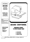
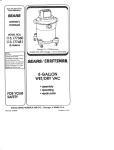
MODEL NO,
113,244501
10-INCH
BAND SAW
Se;iot.....
Number
Model and serial numbers
may be found on the back
of the saw
You should record both
modet and serial number in
a safe place for future use
/
FOR YOUR
SAFETY:
READ ALL
INSTRUCTIONS
CAREFULLY
O-IN©H
e assembUy
® operating
repair parts
../
j
SEARS, ROEBUCK AND CO., Hoffmann Estates, IL 60179 U.S.A.
Part No_ SP5640
Printed in Taiwan
FULL
ONE
YEAR
WARRANT
ONCRAFrSMA.
BENCHTOP
TOOLS
If this Band Saw fails due to a defect in material or workmanship, within one years from the
date of purchase, RETURN IT TO THE NEAREST SEARS SERVICE CENTER IN THE UNITED
STATES, and Sears will repair it, free of charge.
If this Band Saw is used for commercial or rental purposes, this warranty will apply for ninety
days from the date of purchase.
This warranty applies only while this product is in the United States,
This warranty gives you specific legal rights, and you may also have other rights which vary
from state to state.
Sears, Roebuck and Co., D/817 WA Hoffman Estates, IL 60179
'
._
i ,,,,,,,,,,i,,,
,,, i,iH,
Safety Instructions
Safety is a combination of common sense, staying
alert and knowing how your band saw works. Read
this manual to understand this saw.
Safety Signal Words
DANGER: means if the safety information is not followed someone will be seriously injured or killed
WARNING: means if the safety information is not followed someone could be seriously injured or killed.
CAUTION: means if the safety information is not followed someone might be injured_
BEFORE
USING THE SAW:
for Band Saw
• Assembly and alignment. (See pages 7-13).
• Learn the use and function of the ON-OFF
switch, table lock knob, blade guides, backup
bearings, upper slide lock knob, blade guard,
tension catch, and tracking screw. (See pages
14 & 15)
• Review and understand all of the safety instruction and operating procedures in this manual
• Review the maintenance methods for this saw.
(See page 19)
Read the following WARNING labels found on the
front of the saw:
WARNING: To avoid mistakes that could cause
serious, permanent Injury, do not plug the saw
in until the following steps are completed,
WARNING
WHEN INSTALLING
DANGER
OR MOVING THE SAW.
AVOID DANGEROUS ENVIRONMENT Use the saw
in a dry, indoor place protected from rain, Keep work
area well lighted.
To avoid injury from unexpected saw movement:
• Put the saw on a firm level surface where there is
plenty of room for handling and properly supporting the workpiece
• Support the saw so the table is level and the saw
does not rock.
• Bolt the saw to the support surface if it tends to
slip, walk, or slide during operations like cutting
long, heavy boards.
• Turn saw off and unplug cord before moving the
saw.
To avoid injury or death from electrical shock:
• GROUND THE SAW This saw has an approved
3-conductor cord and a 3-prong grounding type
plug Use only 3-wire, grounded outlets rated
120 volts, 15 amperes (amps). The green conductor in the cord is the grounding wire_ To avoid
electrocution,
NEVER
connect
the green
wire to a live terminal
• Make sure your fingers do not touch the plug's
metal prongs when plugging or' unplugging the
saw,.
NEVER STAND ON TOOL. Serious injury could
occur if the tool tips or you accidentally hit the cutting
tool, Do not store anything above or near the tool
where anyone might stand on the tool to reach them.
BEFORE
EACH USE:
Inspect your saw.
DISCONNECT THE SAW To avoid injury from accidental starting, unplug the saw, turn the switch off
and remove the switch key before changing the
setup, opening covers, removing guards, or' blade_
CHECK FOR DAMAGED PARTS. Check for:
, alignment of moving parts,
o binding of moving parts,
o broken parts,
• stable mounting, and
- any other conditions that may affect the way the
saw works.
If anypartis missing,bent,or brokenin anyway,or
anyelectricalpartdoesn'tworkproperly,
turnthesaw
off andunplugthe saw REPLACEdamaged,missing,or failedpartsbeforeusingthesawagain
MAINTAIN
TOOLSWiTHCAREKeepthesawclean
for bestandsafestperformanceFollowinstructions
forlubricating
REMOVEADJUSTINGKEYSAND WRENCHES
fromtoo!beforeturningit on
To avoid injury from jams, slips or thrown pieces:
• Choose the right size and style blade for the
material and the type of cutting you plan to do
• USE ONLY RECOMMENDED
ACCESSORIES
(See page 18) Consult this owner's manual for
recommended accessories
FoIlow the instructions that come with the accessories The use of
improper accessories may cause risk of injury to
persons
• Make sure the blade teeth point downward,
toward the table
Dress for safety,
WEAR
YOUR
Any power saw can throw foreign objects into the
eyes This can cause permanent eye damage Wear
safety goggles (not glasses) that comply with ANSI
Z871 (shown on package)
Everyday eyeglasses
have only impact resistant lenses They are not safety glasses Safety goggles are available at Sears
retait catalog stores Glasses or goggles not in c0m_
pliance with ANSI Z87 ! could seriously hurt you
when they break
• Do not wear Ioose clothing, gloves, neckties or
jewelry (rings, wrist watches)
They can get
caught and draw you into moving parts
• Make sure the blade guides and thrust bearings
are properly adjusted
• Wear nonslip footwear
• Make sure the blade tension is properly adjusted,
• Roll long sleeves above the elbow
. Make sure the table lock knob is tight and no
parts have excessive play
. To avoid accidental blade contact, minimize
blade breakage and provide maximum blade
support, always adjust the upper blade guide and
blade guard to just clear the workpiece
• KEEP WORK AREA CLEAN Cluttered areas
and benches invite accidents Floor must not be
slippery
• Noise levels vary widely To avoid possible hearing damage, wear ear plugs or muffs when using
your saw for hours at a time
To avoid burns or other fire damage, rlever use the
saw near flammable liquids, vapors or gases
• Tie back long hair
• For dusty operations wear a dust mask along
with the safety goggles
Inspect your workpiece_
Make sure there are no nails or foreign objects in the
part of the workpiece to be cut
Use extra caution with large, very small
ward workpieces:
or awk-
• Use extra supports (tables, saw horses, blocks.
etc ) for any workpieces large enough to tip when
not held down to the table top
Plan ahead to protect your eyes,
hands, face, ears.
KNOW YOUR SAW Read and understand the
owner's manual and labels affixed to the tool_ Learn
its application and limitations as well as the specific
potential hazards peculiar to this tool
To avoid injury from accidental contact with moving
parts, don't do layout, assembly, or setup work on the
saw while any parts are moving.
AVOID ACCIDENTAL STARTING Make sure switch
is "OFF" before plugging saw into a power outlet
Plan your work.
• USE THE RIGHT TOOL Don't force tool or
attachment to do a job it was not designed to do
• Use this band saw to cut onty wood, wood like
products, and plastics
• NEVER use another person as a substitute for a
table extension, or as additional support for a
workpiece that is longer or wider then the basic
saw table, or to help feed, support or pull the
workpiece
• When cutting irregularly shaped workpieces, plan
your work so it will not pinch the blade. A piece
of molding, for example, must lay flat or be held
by a fixture or jig that will not let it twist, rock or
slip while being cut
. Properly support round materiat such as dowel
rods, or tubing They have a tendency to roll during a cut, causing the blade to "bite" To avoid
this, always use a "V" block or clamp the work to
the miter gage
• Cut only one workpiece at a time
• Clear everything except the workpiece and related support devices off the table before turning
the saw on
Plan the way you will hold the workpiece
start to finish,
from
Do not hand hold pieces so small that your fingers
will go under the blade guard Use jigs or fixtures to
hold the work and keep your hands away from the
blade
Avoid awkward operations and hand positions where
a sudden slip could cause fingers or hand to move
into the blade
DON'T OVERREACH
WHENEVER
Keep good footing and balance
SAW
IS RUNNING.
Before freeing any jammed material:
• Turn switch "OFF"
• Remove switch key
. Unplug the saw
. Wait for all moving parts to stop
When backing up the
bind in the kerf (cut).
sawdust
clogging up
blade comes out of the
• Turn switch "OFF"
workpiece, the blade may
This is usually caused by
the kerr or because the
guides. If this happens:
° Remove switch key
WARNING: Don't let familiarity (gained from
frequent use of your band saw) cause a
careless mistake. A careless fraction of a
second is enough to cause a severe injury.
Before starting your cut, watch the saw while it runs If it
makes an unfamiliar noise or vibrates a tot, stop immediately Turn the saw off Unplug the saw Do not restart
until finding and correcting the problem
KEEP CHILDREN AWAY Keep all visitors a safe distance from the saw Make sure bystanders are clear of
the saw and workpiece
DON'T FORCE TOOL. It will do the job better and safer
at its designed rate Feed the workpiece into the saw
blade only fast enough to let it cut without bogging
down or binding
• Unplug saw
• Wait for all moving parts to stop
• Open band saw cover
• Stick flat blade screwdriver
kerf
or wedge into the
• Turn the upper wheel by hand while backing up
the workpiece
Before removing loose pieces from the table, turn
saw off and wait for all moving parts to stop.
BEFORE
LEAVING
THE SAW:
Wait for a!l moving parts to stop
Make workshop
child-proof.
Lock the shop
Disconnect master switches
Remove the yellow
switch key Store it away from children and others not
qualified to use the tool
gnossaty of terms for woodworking
Beveling
An angle cutting operation through the face of the
board
Crosscut
A cutting operation made across the width of the
workpiece
Compound Cutting
A simultaneous bevel and miter cutting operation
FPM
Feet per minute Used in reference to surface speed
of blade
Freehand (as used for band saw)
Performing a cut without the workpiece properly supported on the work table
Gum
A sticky, sap-based residue from wood products
Kerf
The material removed by the blade in a through cut or
the slot produced by the blade in a non-through or
partial cut
Leading End
The end of the workpiece which is pushed into the
cutting tool first
Mitering
An angle cutting operation made across the width of
the workpiece
Push Stick
A device used to feed the workpiece through the saw
during narrow ripping type operations so the operatot's hands are kept well away from the blade.
Resaw
A cutting operation to reduce the thickness of the
workpiece to make thinner pieces
Resin
A sticky, sap-based substance that has dried
Ripping
A cutting operation along the length of the workpiece
Sawblade Path
The area of the worktable or workpiece directly in line
with the saw blade
Set
The distance the tip of the saw blade tooth is bent
outward from the face of the blade
Tracking
Adjusting the upper wheel so the bandsaw blade runs
in the center of the wheels
Trailing End
The workpiece end last cut by the saw blade
Workpiece
The item or] which the cutting operation is being performed The surfaces of a workpiece are commonly
referred to as faces, ends, and edges
Worktable
The surface on which the wofkpiece rests while performing a cutting operation
motor specifications and eRectrBcan
requBrements
This machine is designed to use, and is equipped with,
a 1725 RPM motor It is wired for operation on 120
volts, 60 Hz., alternating current (TOOL MUST NOT
BE CONVERTED TO OPERATE ON 230 VOLT)..
For replacement motor refer to parts list in this manual.
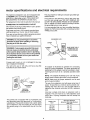
CONNECTING TO POWER SUPPLY OUTLET
This machine must be grounded while in use to protect
the operator from electric shock.
Plug power cord into a 120V properly grounded type
outlet protected by a 15-amp fuse or circuit breaker.
This plug requires a mating 3-conductor grounded type
outlet as shown.
If the outlet you are planning to use for this power tool
is of the two prong type, DO NOT REMOVE OR
ALTER THE GROUNDING PRONG iN ANY MANNER
Use an adapter as shown below and always connect
the grounding tug to a known ground.
It is recommended that you have a qualified electrician
replace the TWO prong outlet with a properly grounded
THREE prong outlet.
if you are not sure that your outlet is property grounded,
have it checked by a quafified electrician.
GROUNDING
WARNING: Do not permit fingers to touch the
terminals of plugs when installing or removing
the plug to or from the outlet.
WARNING: If not properly grounded this power
tool can cause an electrical shock, particularly
when used in damp locations close to plumbing,
If an electrical shock occurs there is the potential
of a secondary hazard such as your hands contacting the saw blade.
PLUG
//,')_
I _.
LUG
_-_
_
CONNECTED
"
"_
TO A
2-PRONG
RECEPTACLE
ADAPTER
If power cord is worn or cut, or damaged in any way,
have it replaced immediately.
Your unit is for use on !20 volts, and has a plug that
looks like the one shown below
An adapter as illustrated is available for connecting
plugs to 2-prong receptacles. The green grounding lug
extending from the adapter must be connected to a permanent ground such as to a properly grounded outlet
box
NOTE: The adapter illustrated is for use only if you
already have a properly grounded 2-prong receptacle.
3-PRONG
PLUG
PRONG
PROPER_
GROUNDED
3-PRONG OUTLET
This power toot is equipped with a 3-conductor cord
and grounding type plug approved by Underwriters'
Laboratories. The ground conductor has a green jacket
and is attached to the tool housing at one end and to
the ground prong in the attachment plug at the other
end
NOTE: Make sure the proper extension cord is used
and is in good condition
The use of any extension cord will cause some loss of
power. To keep this to a minimum and to prevent overheating and motor burn-out, use the table below to
determine the minimum wire size (A.W.,G) extension
cord
Use only a single cord when an extension cord is
required.. The cord must be a 3 wire extension cord
which has a 3-prong receptacle that will accept the
tools plug.
Length of the
Cord
25 Feet
50 Feet
100 Feet
Wire Sizes Required
(American Wtre Gage Number)
120V Lines
No.. t6
No. 16
No. 16
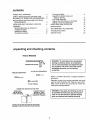
contents
POWER TOOL WARRANTY .....................................
2
SAFETY INSTRUCTIONS FOR BAND SAW .............. 2
GLOSSARY OF TERMS FOR WOODWORKING .... 4
MOTOR SPECIFICATIONS
REQUIREMENTS
............
AND ELECTRICAL
.............................................
5
UNPACKING AND CHECKING CONTENTS .......... 6
ASSEMBLY
Mounting Band Saw to Workbench ................
Installing the Table ...............................
Installing the Blade ........................................
Tensioning the Blade .....................................
7
8
9
10
Tracking the Blade ..............................................
Adjusting the Blade Guides and
Back-Up Bearing ....................................
Final Table Assembly ...........................................
Aligning the Table Square to the Blade ............
Getting to Knew your Band Saw ..........................
BASIC BAND SAW OPERATION ......................
1!
12
12
13
15
MAINTENANCE .........................................
18
RECOMMENDED
18
ACCESSORIES
...................
TROUBLESHOOTING
......................
REPAIR PARTS ............................
11
19
20
unpacking and checking contents
TOOLS
NEEDED
[,','",q", I"
• =- i'"1"_"_"'_"
COMBINATION
'
SQ
WARNING: To avoid injury from unexpected
starting or electrical shock, do not plug the
saw in until all assembly and alignment steps
are complete. The power cord must remain
unplugged whenever you are working
on the saw.
#2 PHILLIPS SCREWDRIVER
MEDIUM SCREWDRIVER
Model 113244501
one carton
1/2 INCH WRENCH
COMBINATION
DRAW-LIGHT
LINE ON BOARD
SQUARE
Band Saw is shipped complete in
Separate all parts from packing materials and check
each item with illustration and "Table of Loose Parts"
Make certain all items are accounted for, before discarding any packing material
MUST BE TRUE
STRAIGHT EDGE OF
BOARD 314"THICK
ALONO
1.,S
SHOULD BE NO GAP OR OVERLAP HERE WHEN
SQUARE tS FLIPPED OVER IN DOn"ED POSITION
WARNING: tf any parts are missing, do not try
to assemble the band saw, plug in the power
cord, or turn the switch on until the missing
parts are obtained and installed correctly,
ITEM
TABLE OF LOOSE PARTS
QTY.
=
A
B
C
D
C
Basic saw assembly ............................
Owners Manual .....................................
Saw Table ...........................................
1
1
t
Loose Parts Bag
Containing the following parts:
Key Switch .........................................
Wing Nut t/4-20 x 5/8 ..........................
Screw, Truss Hdo 1/4-20 ..................
Wrench, Hex "L" 1/8 .........................
Bevel Indicator
Screw, Pan Cross 10-32 x 3/8 ............
Washer 17/64 x 1 x 1/16 .....................
Bolt, Carriage I/4-20 x 1....................
Knob ......................................................
Clip Hose ..............................................
1
1
1
1
1
1
1
1
1
1
....................................
assernbBy
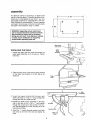
MOUNTING BAND SAW TO WORKBENCH
If band saw is to be used in a permanent location, it
should be fastened securely to a firm supporting surface such as a workbench
NOTE: All bolts should be inserted from the top
tnstall the washers and nuts from the underside of the
bench
If mounting to a workbench, holes should be drilled
through supporting surface of the workbench using
dimensions illustrated,
1 Each leg should be bolted securely using 5/16"
diameter machine screws, Iockwashers, and 5/16"
hex nuts (not included)Screw
length should be
1-3/4" plus the thickness of the bench top,
2 Locate and mark the holes where band saw is to
be mounted
5"'
3/8" DIAMETER
(4) HOLES
3 Drill (4) 3/8" diameter holes through workbench,,
4, Place band saw on workbench aligning
feet with holes drilled in workbench
holes in
5 Insert all four 5/16" screws and tighten,
i
i
i ii 1,1,,
CLAMPING
, ii ,,11,i,l,ll,llr
BANDSAW TO WORKBENCH
The Band Saw can be clamped directly to a workbench LJsingtwo (2) or more "C" clamps on base of
unit
"C" Clamp
Workbench
assembOy
An alternate method of mounting is to fasten band
saw to a mounting board The board should be of sufficient size to avoid tipping el saw while in use Any
good grade of plywood or chipboard with a 3/4" minimum thickness is recommended, (Thinner chipboard
can break ) Once the saw is mounted, securely clamp
the board to the workbench using "C" ;:lamps
24
MIN
......
.......
t
18' MIN,
WARNING: Supporting surface where band
saw is mounted should be examined carefully
after mounting to insure that no movement
during use can result, tf any tipping or walking
is noted, secure workbench or supporting
surface before operating band saw.
Upper Slide
Lock Knob
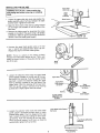
INSTALLING
THE TABLE
Upper
Guide
Assembly
1 Loosen the upper slide lock knob and position the
upper guide assembly atl of the way up Tighten
lock knob
2 Open the front cover of the saw by pulling forward
on the finger hold located on the left side of the
band saw
Finger
Ho_d
3 Locate the square hole behind the lower right
wheet and insert a 1/4-20 x 1" long carriage bolt
through this hole from inside the saw
4" Position the table-trunnion assembly on the back
side of the saw so the 1/4-20 x l" boit extends
through the curved slot in the trunnion The trunnion should engage the curved mounting rib on the
back side of the saw
5, Install the t" outside diameter washer and table
lock knob to the end of the bolt and tighten by
hand
,
[
Trunnion
Trunnion Slots
Table Lock
Knob
/
!o
INSTALLING
THE BLADE
Upper Slide
Lock Knob
and unplug saw before removing or installing
I blade°
ARNING:Turn off saw, remove switch key
Upper
Guide
AssembI
I Loosen the upper slide lock knob and position the
guide assembly about half way between the table
and the frame Tighten the !ock knob
2 Open th_ front cover of the saw by pulling forward
on the finger hold located on the left side of the
band saw
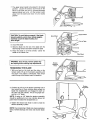
3 Remove the blade guard by loosening the screw
located on the side of the guard using a #2 phiffips
screwdriver Slide the guard up and pull forward to
remove it from the blade guide support
4 Unscrew the upper blade guides using a !/8 inch
hex "L" wrench and separate them about I/8 inch
Repeat this step for the lower blade guides
NOTE: There is a patch on the blade guide(s)
threads that makes them difficult to turn This is necessary to prevent rotation of the guides during operation of the saw
Guide
Blade
_'_'_"(_
i
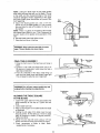
5 Loosen the setscrew which locks the upper blade
guide support (located on the left side of the support behind the bearing) Push the support all the
way back Loosen the setscrew holding the upper
back-up bearing (Located on the right side of the
upper slide) Push the bearing all the way back
With the guide support and back-up bearing
pushed back, slightly tighten both set screws
, ilillilill
illiq;
lil/
i
lii
liiiiiiilll
,
Upper Slide _
Upper Blade
Guide Support
Set Screw
Upper
k-Up Bearing
Set Screw
Bac Blade
Bearing
BLADE GUARD
Guide Support
REMOVED FOR
CLARITY
= m.llJ
i.=..,i
== N.=..,,I
6 Loosen the setscrew which locks the lower blade
guide support (accessed through notch in frame
located below table) Push the support all the way
back Loosen the setscrew holding the lower backup bearing Push the bearing all the way back
With the guide support and back-up bearing
pushed back, tighten both set screws,
=,,.
Set Screw
L
P
LowerBack-UpBearing
.....
Table Removed For
Visual Clarity
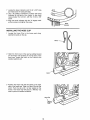
7 The upper wheel needs to be placed in its lowest
position
Locate the tension lock knob on the
back of the saw and turn it counterclockwise
approximately
two turns Lift the tension catch
away from the teeth and move it to its lowest
position
Tension
Catch
illlll.......................................
CAUTION: To avoid being scraped, if the blade
should suddenly uncoil, wear safety goggles.
Carefully uncoil the blade holding it at
arms length.
Drive Wheel!
TensionWheel
Slot in Table
8 Uncoil the blade
1
9_ Slide the blade into the slot of the table with the
teeth facing forward and down toward the table
10 Place the blade on all three wheels Center the
blade on the rubber tires
r Wheel
ill,,!lii,l,l,,,llll,i
WARNING: Turn off saw, remove switch key
and unplug before making arty adjustments.
Tension
/
Aot..,,ng
TENSIONING THE BLADE
1._With one hand on the knob and the other on the
tension catch, lift up on the tension assembly until
the slack in the blade is eliminated. Note which
notch the top of the tension catch is closest to.
Tension
Lock Knob
2_ Continue to pult up on the tension assembly until it
has moved two or three notches above where the
blade first straightened out. Engage the teeth on
the catch into the notches. This is the proper tension for a !/4" blade.
NOTE: If using an 1/8" blade the tension assembly
should be positioned one to two notches above the
point where the blade first straightened out.
3. Tighten the tension lock knob in order to hold the
tension assembly in place,
NOTE: Over tensioning of blade carl cause excessive
wear of wheel bearings and motor and shorten blade
life.
10
]
WARNING:
and
unplug Turn
before
offmaking
saw, remove
any adjustments°
switch key
TRACKING
J
|
Tracking Adjustment
Set Screw
THE BLADE
Blade tension must be properly adjusted before
tracking the blade.
1 Slowly turn the upper wheel clockwise by hand
and watch the blade on the tire If the blade moves
away from the center of the tire the tracking will
have to be adjusted
2 Insert a 1/8" hex wrench into the tracking adjustment screw located on the back of the saw behind
the upper wheel
3 a If the blade moved toward the front of the saw
turn the adjustment screw in (clockwise) while
turning the wheel by hand, until the blade rides
in the center of the tire
b If the blade moved away from the front of the
saw turn the adjustment screw out (counter
clockwise) while turning the wheel by hand, until
the blade rides in the center of the tire
4 Check the position of the btade on the other tires
The blade should be completely on the tire If not,
adjust the tracking until the blade is on all three
tires
5 Rotate the upper wheel by hand in a clockwise
direction for a few more turns Make sure the blade
stays in the same location on the tires Readjust if
necessary, until blade is tracking properly
m
ii M
I'll I I'I'IH'II,
II
WARNING: Turn off saw, remove switch key
and unplug before making any adjustments.
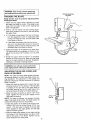
ADJUSTING THE BLADE GUIDES
BACK-UP BEARING
]
J
AND
NOTE: The upper and lower blade guides and backup bearings support the band saw blade during cutting operations
The adjustment of the guides and
bearings should be checked whenever a different
blade is installed
1 Ad)ust the back-up bearing first Loosen the rear
set screw using a 1/8" hex wrench (This set screw
is located on the right side of the upper slide for
the upper bearing and on the right side of the
frame just below the table for the lower bearing )
2 Move the back-up bearing to within 1/32" of the
b{ade Tighten the rear set screw Repeat on the
other back-up bearing
NOTE: The back-up bearing is to support the back
edge of the blade while cutting The blade should not
contact the bearings when you stop cutting
3 Adjust the position of the blade guide support next
Loosen the front set screw using a 1/8" hex
wrench (This set screw is located on the left side
of the support for the upper guides and the right
side for the lower guides )
Thrust
Bearing
4 Slide the b_ade guide support on the shaft until the
front edge of the blade guides are about 1/32"
behind the gullet of the blade Tighten the set
screw Repeat for the other guide
11
NOTE: Letting the blade teeth hit the blade guides
while using the band saw will ruin the blade° The set
of the teeth and the sharpened edge of the teeth
would be damaged Proper adjustment of the upper
and lower blade guide assemblies wil! prevent this
from happening
5 Adjust the blade guides last Use a 1/8" hex
wrench to turn the blade guides in or out to where
they just clear the side of the blade Do this for all
four guides
NOTE: There is a patch on the blade guide threads
that makes them difficult to turn This is necessary to
prevent rotation of the guides during operation of the
Saw
Biade
saw
6 Reinstall blade guard and tighten screw
7 Close the front cover of the saw
Blade
Guides
WARNINGI Never start the saw with the cover
pen. Thrown blades can cause injury,
,_.._ Truss Head
Screw
FINAL TABLE ASSEMBLY
1 Close the front cover of the band saw and snap in
place
2, Locate a 1/4-20 x 5/8 truss head screw, and a 1/420 wing nut in loose parts Insert screw into hole in
table top as illustrated
3 From the underside of the table, install wing nut
onto the truss head screw and tighten finger tight
This will keep the table flat and in alignment
Nut
unplug
before making
adjustments.
WARNING:Turn
off saw,any
remove
switch key and
Combination
ALIGNING THE TABLE SQUARE
TO THE BLADE
1 Loosen the upper slide lock knob and position the
guide assembly all the way up Tighten the lock
knob
2 Loosen table lock knob
3 Place a small square on the table beside the blade
as illustrated,
4 Holding the teft edge of the table (near the zero
stop set screw), tilt the table up or down to align
tabte 90 degrees to blade (0 degree position)
Tighten lock knob
5 Adjust the zero stop set screw using a 1/8" hex
wrench until the set screw just touches the frame
6 Check squareness of blade to table Make
readjustments if necessary
Zero Stop
Screw
12
7 Locatethe bevelindicatorand 10-32x 3/8"long
panheadscrewin loosepartsbag,
8 Usea #2 phillipsscrewdriver
to attachthe bevel
indicatorto the backof the frame,in the small
recessbelowthe trunnion,with the 10-32x 3/8"
screw
9 Alignthebevelindicatorwiththe "0"degreemark
onthetrunnionandtightenthescrew
,I,I
,.dlc o.
....i i ul, ll,, i,Ul ,i,
INSTALLING
!
THE HOSE CLIP
Locate the Hose Clip in the loose parts
Identify the barbs on the clip
bag
Barbs
2, Open the front cover of the saw by pulling forward
on the finger hold located on the left side of the
band saw, Locate the notch in the Frame at the
sawdust ejection port
Notch
3 Position the Hose Clip with the barbs to the back
side of the band saw Slide the Hose Clip into the
notch Push the clip until it is fully seated on the
Frame The Hose Clip will secure a Wet/Dry vac
hose in place for sawdust collection,
Hose Clip
13
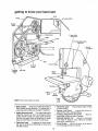
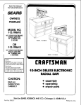
getting to know your band saw
Cover
Frame
9 Wrench Holder
Tension
Catch
2 Upper Slide
Lock Knob
. Table
Tracking Adjustment
Set Screw
5 Tension
Lock Knob
8 Cover Hinges
10 On-Off
Switch
7 Sawdust
Ejection
Port
Hose Clip
1 Blade
Guides
4 Beve
Scale
Bevel
indicator
3 Table
Lock
Knob
NOTE: Cover shown open for clarity
..................................................
=r,H,,=l=
=ll,i H=
=
1,. Blade Guides..
Supports the blade and keeps it
from twisting during operation, An adjustment is
necessary when blades are changed or replaced
ii
H
=H==
,i
=
ill=
,i,i
=f,l=
................
4, Tilt (bevel) scale •
Shows degree table is t/Ited
for bevel cutting
5 Tension Lock Knob • • controls the amount of
blade tension when changing blades
6 Tracking Adjustment Set Screw _ ,, adjust to
keep blade running in center of wheels,
7 Sawdust Ejection Port
, sawdust is eliminated
from inside of machine Also. makes an exceJlent
hook-up for a Wet/Dry vac
8 Cover Hinges
allows front cover to be opened
for making adjustments to machine
2. Upper slide lock knob
, The upper' blade guide
assembly should just clear the workpiece while
cutting Always adjust the upper guide assembly
and lock the upper slide by tightening the upper
slide lock knob before turning on the band saw,
3 Table lock knob , , Loosening the knob allows
the table to be tilted and tightening the knob locks
the table in place.
14
9 WrenchHolder Keeps1/8"Hex'L" Wrench
conveniently
locatedforbladeguideadjustments
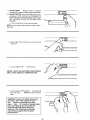
10 ON-OFFSWITCH.TheOn-OffSwitchhasa locking feature THIS FEATURE IS INTENDED TO
HELP PREVENT UNAUTHORIZED AND POSSIBLY HAZARDOUS USE BY CHILDREN AND
OTHERS
a To turn machine on, insert key into switch
NOTE: Key is made of yellow plastic; locate in Ioose
parts bag
b Insert finger under switch lever and putt end of
switch out
c To turn machine OFF
PUSH lever in
NEVER LEAVE THE MACHINE
UNATTENDED
UNTIL IT HAS COME TO A COMPLETE STOP.
.....
i,
i,
,
d To lock switch in OFF position . hold switch IN
with one hand
REMOVE key with other
hand
WARNING: For your own safety, always lock
the switch "OFF" when machine is not in
use.,,
remove key and keep it in a safe
place.,, also. ,, in the event of a power failure
(all of your lights go out) turn switch off. _.
remove the key and store it away from
band saw. This will prevent the machine
from starting up again when the power
comes back onr
\
\
15
,i
iiiii
Basic Saw Operations
BEFORE
• To avoid accidental blade contact, minimize btz
breakage and provide maximum blade supp_
always adjust the upper blade guide and bla,
guard to just clear the workpiece
EACH USE:
Inspect your saw.
DISCONNECT THE SAW To avoid injury from accidental starting, unplug the saw, turn the switch off
and remove the switch key before changing the
setup, opening covers, removing guards, or blade
• KEEP WORK AREA CLEAN Cluttered areas an
benches invite accidents Floor must not be slip
pery
To avoid burns or other fire damage, never use the saw
near flammable liquids, vapors or gases
CHECK FOR DAMAGED PARTS. Check for:
• alignment of moving paris,
Plan ahead to protect your eyes, hands,
face, ears.
• binding of moving parts,
• broken parts,
• stable mounting, and
• any other conditions that may affect the way the
saw works.
If any part is missing, bent, or broken in any way, or
any electrical part doesn't work properly, turn the saw
off and unplug the saw REPLACE damaged, missing, or failed parts before using the saw again
MAINTAIN TOOLS WITH CARE Keep the saw clean
for best and safest performance
KNOW YOUR SAW Read and understand the owner's
manual and labels affixed to the tool Learn its applica:
tion and limitations as well as the specific potential hazards peculiar to this tool
To avoid injury from accidental contact ,with moving
parts, don't do layout, assembly, or setup work on the
saw while any parts are moving
AVOID ACCIDENTAL STARTING Make sure switch is
"OFF" before plugging saw into a power outlet
Plan your work.
• USE THE RIGHT TOOL Don't force tool or attachment to do a job it was not designed to do
REMOVE ADJUSTING
KEYS AND WRENCHE, S
from tool before turning it on
• Use this band saw to cut only wood, wood like
products, and plastics
To avoid injury from jams, slips or thrown pieces:
• Choose the right size and style blade for the
material and the type of cutting you plan to do
• USE ONLY RECOMMENDED ACCESSORIES
(See page 18) Consult this owner's manual for
recommended accessories Follow the instructions that come with the accessories The use of
improper accessories may cause risk of injury to
persons.
• Make sure the blade teeth point downward,
toward the table
Dress for safety.
Any power saw can throw foreign objects into the eyes
This can cause permanent eye damage Wear safety
goggles (not glasses) that comply with ANSI Z87 1
(shown on package) Everyday eyeglasses have only
impact resistant lenses The are not safety glasses
Safety goggles are available at Sears retail catalog
stores Glasses or goggles not in compliance with ANSI
Z87.1 could seriously hurt you when they break
• Make sure the blade guides and thrust bearings
are properly adjusted
• Do not wear loose clothing, gloves, neckties or
jewelry (rings, wrist watches) They can get caught
and draw you into moving parts
• Make sure the blade tension is properly
adjusted
• Wear nonslip footwear
. Make sure the table lock knob is tight and no
parts have excessive play
- Roll long sleeves above the elbow
• Tie back long hair
16
WHENEVER
• Noise levels vary widely To avoid possible hearing damage, wear ear plugs or muffs when using
your saw tot hours at a time
SAW iS RUNNING.
WARNING: Don't let familiarity (gained from
frequent use of your band saw) cause a careless mistake. A careless fraction of a second is
enough to cause a severe injury.
• For dusty operations, wear a dust mask along
with the safety goggles
Inspect your workpiece,
Make sure there are no nails or toreign objects in the
part of the workpiece to be cut
Before starting your cut, watch the saw while it runs If it
makes an unfamiliar noise or vibrates a lot, stop immediately, Turn the saw off Unplug the saw Do not restart
unlit finding and correcting the problem
Use extra caution with large, very small or awkward
workpieces:
KEEP CHILDREN AWAY Keep all visitors a safe distance from the saw Make sure bystanders are clear of
the saw and workpiece
• Use extra supports (tables, saw horses, blocks,
etc ) for any workpiece large enough to tip when
not held down to the table top
• NEVER use another person as a substitute
table extension, or as additional support
workpiece that is longer or wider then the
saw table, or to help feed, support or pull the
piece
DONT FORCE TOOL It will do the job better and safer
at its designed rate Feed the workpiece into the saw
blade only fast enough to let it cut without bogging
down or binding
for a
for a
basic
work-
Before freeing any jammed material:
• Turn switch "OFF"
• When cutting irregularly shaped workpieces, plan
your work so it will not pinch the blade A piece of
molding, for exampfe, must lay flat or be held by a
fixture or jig that will not let it twist, rock or slip while
being cut
• Remove switch key
• Unplug the saw
• Wait for all moving parts to stop
Properly support round materiai such as dowel
rods, or tubing They have a tendency to roll during
a cut, causing the blade to "bite" To avoid this,
atways use a 'V' block or clamp the work to the
table
When backing up the workpiece, the blade may
bind in the kerf (cut). This is usually caused by
sawdust clogging up the kerf or because the blade
comes out of the guides. If this happens:
• Turn switch "OFF"
• Cut only one workpiece at a time
• Remove switch key
• Clear everything except the workpiece and retated
support devices off the table before turning the
saw
, Unplug saw
• Wait for all moving parts to stop
on
- Open band saw cover
• Stick flat blade screwdriver or wedge into the kerf,
Plan the way you will hold the workpiece from start
to finish.
• Turn the upper wheel by hand while backing up the
workpiece
Do not hand hold pieces so small that your fingers will
go under the blade guard Use jigs or fixtures to hold
the work and keep your hands away from the blade
Before removing loose pieces from the table, turn
saw off and wait for all moving parts to stop.
Avoid awkward operations and hand positiondwhere a
sudden slip could cause fingers or hand to move into
the blade
BEFORE LEAVING THE SAW:
DON T OVERREACH
Wait for all moving parts to stop
Make workshop child-proof Lock the shop Disconnect
master switches Remove the yellow switch Key Store
it away from children and others not qualified to use the
tool.
Keep good footing and balance
17
Saw
Kerr
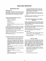
basic band saw operation
Workplece
A band saw is basically a "curve cutting" machine It
is also used for straight-line cutting operations such
as cross cutting, ripping, mitering, beveling, compound cutting, and resawmg
It is not capable of
doing inside cutting,
?
This band saw is designed to cut wood and wood
like products only,
For general type
by pushing and
time Don't try to
the blade without
or twist the blade
Pattern Line
scroll cutting, follow the pattern lines
turning the workpiece at the same
turn the workpiece while engaged in
pushing it; the workpiece could bind
Blade
RIGHT
- Planning ahead by turning workpiece for
cutting a curve
NOTE: Blade guard is raised and right hand removed
for clarity of picture only
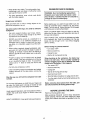
A curve cut is best performed by keeping the pattern
line in line with the blade while turning the workpiece
before the radius of the curve is cut,. The blade
should cut in the middle of the pattern line (saw kerf)
since wood cutting band saw blades are thin
Workptece
NOTE: Blade guard is raised and right hand removed
for clarity of picture only
Pattern Line
Blade
WRONG
- Not planning ahead for cutting a curve
could bind or twist blade if workpiece is forced
NOTE: Blade guard is raised and right hand removed
for clarity of picture only
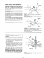
WARNING: To avoid blade contact, adjUst the
upper guide assembly to just clear the
workpiece,
Workplece
\
l r, Use both hands while feeding the work into the
blade, Hold the workpiece firmly against the table,
Use gentle pressure Do not force the work, but
allow the blade to cuL
Blade
2 The smallest diameter' circle that can be cut out is
, determined by the width of the blade,, A 1/4" wide
blade will cut a minimum diameter' of approximately 1-1/2" A 1/8" wide blade will cut a minimum
diameter of approximately 1/2",
Relief Cuts
Relief cuts are made when an intricate curve (too
small a radius for the blade) is to be cut buL A relief
cut is made by cutting through the scrap section of
workpiece to curve in pattern line, then carefully
backing blade out Several relief cuts should be made
for intricate curves, then follow pattern line as sections are cut off of curve "relieving" blade pressure,
/
PatternLine
NOTE: Blade guard is raised and right hand removed
for clarity of picture only,
18
maintenance
WARNING: For your own safety, turn switch
"OFF", remove switch key and remove plug
from power outlet before maintaining
or lubricating your band saw.
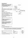
Wiring Diagram
{ co,a ,lo,
t
TIRES
Pitch and sawdust that accumulates
on the tires
should be removed with a stiff brush or scraped off
with a piece of wood Do not use a sharp knife or any
kind of solvent
White
While
GENERAL
Black
Keep your Band Saw clean
Remove sawdust from the inside frequently
.J__Green
Do not allow pitch to accumulate on the table, blade
guides,
or thrust bearings
Clean them with
Craftsman Gum and Pitch Remover
Ground
Screw
Apply a thin coat of automobile-type wax to the table
top so the wood slides easily while cutting Also apply
wax to the inside surfaces of the trunnion
MOTOR/ELECTRICAL
Frequently vacuum or blow out any sawdust from the
motor
or damaged in any way, have it
f WARNING:
If the power cord is worn, cut,
replaced immediately.
WARNING: To avoid fire or electrocution,
reassemble electric parts with only approved
service parts. Reassemble exactly as
originally assembled.
LUBRICATION
A!t of the BALL BEARINGS are permanently lubricated They require no further lubrication
_,
i
i
IM I1,,I,'
III
I_
It1
III
I
I
sears recommends the following
Ir
I
IIII
'1 I
accessories
Sears may recommend other accessories not listed in
manual
Item
See your nearest Sears Store or Catalog Department
for other accessories
Blades (56-7/8" length) .........................
Do not use any accessory unless you have received
and read complete instructions for its use
Cat. No.
Miter Gauge
_)-24214
...............................................
Leg Set
Power Toot Handbook
See Catalog
...................................................
19
..............................
9-22244
9-29117
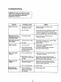
troubleshooting
WARNING: For your own safety, turn switch
"OFF", remove switch key and remove plug
from power outlet before readjusting or
aligning your band saw.
PROBABLE CAUSE
TROUBLE
Motor will not run.
t
REMEDY
1 Replace damaged parts before using
Band Saw again
Damaged On-Off switch
Damaged power cord
2 Consult Sears Service, Any attempt to repair this
motor may create a HAZARD unless repair
is done by a qualified service technician Repair
service is available at your nearest Sears Store.
2 Motor Damaged,
Blade does not run in
the approximate center
of the upper wheel.
1 Not tracking properly
Band Saw slows down
when cutting.
1, Cutting too small a radius
.
Adjust tracking, see Assembly Section,
"Tracking the Blade"
Stop feeding, and back up the material slightly,
until the band saw speeds up,
Replace blade,
2 Dutl blade,
mm
Blades breaking=
1, Too much tension,
v
Saw is noisy when
running.
Kink in blade caused by
cutting too small a radius
or turning the material too
fast when cutting
1 Too much blade tension
2, Blade guides and back_up
bearings are in contact with
the blade.
Blade will not cut
straight.
Blade guides will
not stay in position
14 Adjust tension, See Assembly section
"Tensioning The Blade,"
2, Use correct cutting technique° See Basic
Band Saw Operation Section.
.,
Adjust blade tension. See Assembly section
"Tensioning The Blade"
.
Adjust upper and lower blade guides and
bearings. See assembly section "Adjusting the
Blade Guides and Back-up Beating,"
1 Blade guides and bearings
not, properly adjusted.
Adjust upper and lower' blade guides and
bearings See Assembly section "Adjusting
Guides and Back-up Bearing,."
2, Worn or damaged blade,
Replace blade
1, Replace blade guides,
Patch on blade guide
threads has deteriorated
allowing them to rotate
with the blade,
20
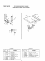
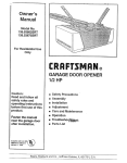
repair parts
FOR
10-INCH
BAND
SAW
113.244501
Always order by Part Number - Not by Key Number
2
4
4
5
6
FIGURE
NO
Part
No.
1
2
820286
ST D601103
3
817899
4
5
6
7
STD502502
820279
820281
820284
1
Description
i,in,,ll,,=
Guard Blade
. Scr Pan HD TY "TT"
10-32 x 3/8
Scr Soc Set 1/2 Dog Pt
1/4-20 x 1/2
" Scr Soc Set 1/4-20 x 114
Support Guide
Shaft w/Bearing
Slide Upper
FIGURE 2
Pad
Key
NO,,,II,
1
2
3
4
5
6
u
Description
No,
60323
817935
820874
817915
815865_2
817149
, i, i1,,
i,i, i....
i,i i i1,1
,lilt
Scr Truss 1/4-20 x 5/8
Table
Nut Wing Low Profile I/4-20
Trunnion
Scr Hx Hd TYTT 1/4_20 x 5/8
Scr Locking Set 1/4-20
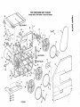
FOR 10-INCH
BAND SAW 113.244501
Always order by Part Number-
40
Not by Key Number
=m=lm
:E FIGURE 2
45
_,..1
23
9
18
.,
.
_
6
6
7
_
10
"_"
11
SEE 24
FIGURE 1
"_l
to
46
SEE FIGURE 1
7
\_
_
12
10
6
32
23
22
15
31
48
6
11
14
13
FIGURE 3
....
[
47
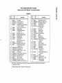
FOR IO-INCH
BAND SAW 113.244501
Always order by Part Number-
Not by Key Number
FIGURE 3
Key
No
Part
1
3
4
820288
STD541031
STD551131
820269
5
6
7
816087
818146
820266
Description
=nil
8
9
10
11
12
9-28137
9-26653
817911
817453-2
821725
!3
14
15
817943
STD551037
820277
16
17
18
19
20
21
22
23
24
25
STD541025
STD551225
STD551025
820265
STD522507
STD551210
STD541110
820264
STD532510
STD502502
n,,
Pin Hinge
Nut, Hex 5/16-18
Lockwasher 5/16
Support Wheel (Includes Key
No?s 2, 3 & 23)
ScrTr Cr Hd 1/4-20 x 1/2
Washer Nylon
Wheel tdler (Includes
Key No, 10)
* Wrench, Hex L 1/8
tBand Saw Blade 56-7/8
BandsawTire
Retaining Ring
Cover Front
(includes Key No. 46)
* NUt 3/8-16 L.H.
* Washer 3/8 x 3/4 x 1/32
Wheel Drive (Includes
Key No. 10)
* NUt, Hex 1/4-20
* Lockwasher 1/4
*Washer 17/64 x 1 x 1/16
Foot Frame
* Screw Hex Hd 1/4-20 x 3/4
* Lockwasher Int NtO
* Nut, Hex 10-32
Shaft - Wheel
* Belt Crge 1/4-20xl
*Screw Soc. Set t/4-20 x 1/4
Key
No
Pad
26
27
28
29
3O
820272
STD532525
820088
817944
STD511103
31
32
33
34
35
36
37
38
820493
816464
813989-1
STD375006
820273
9-22256
816113
STD600803
39
4O
41
42
43
44
820274
61400
817149
820276
69164
STD512505
45
82I 679
46
47
48
-
821157
STD551237 ', Gasket
Lockwasher 3!8
821288
Washer 1/2 x I x ,039
SP5640
Owners Manual
(Not tUustrated)
NO,
Description
t_
,mn,,,n,,=l
Spring Blade Tension
* Bolt Crge 1/4-20 x 2-1/2
Catch Blade Tension
Indicator Bevel
* Screw Pan HD
! 0-32 x 3/8
Clip Hose
Latch Cover
Cord w/Plug
* Connector Wire
Motor
t Key Switch
Switch Locking
* Screw Pan HD TY 'TF"
8-32 x 3/8
Capacitor
Knob 1-3/8 Dia.
Screw Lock Set 1/4-20
Plate Cover
Relief-Strain
Screw Pan HD
1/4-20 x 1/2
Frame (includes Key No,'s
2, 3 & 23)
-t-Stock item - May Be Secured Through The Hardware Department Of Most Sears Retail Stores Or
Catalog Order Houses.
* Standard Hardware item - May Be Purchased Locally.
1
For the repair or replacement parts you need
Call 7 am - 7 pm, 7 days a week
t -800-366-PART
(1-800-365-7278)
MODEL NO.
For in-home major brand repair service
Call 24 hours a day, 7 days a week
t =800=4=REPAIR
(1-800-473-7247)
The model number of your
10-Inch Band Saw will be
found on a plate located on
the back of the Band Saw
below the motor.
When requesting service or
ordedng parts, always
provide the following
Information:
°
*
•
•
Product Type
Model Number
Part Number
Part Description
For the location of a
Sears Repair Service Center in your area
Call 24 hours a day, 7 days a week
1 =800..488-
t 222
For information on purchasing a Sears
Maintenance Agreement or to inquire
about an existing Agreement
Ca!l 9 am - 5 prn, Monday-Saturday
t =800=827=6655
j
America's
Repair
Specialists
SEARS, ROEBUCK AND CO., Hoffmann
Part No, SP5640
Form No, SP5640 -t
j
Estates, IL 60179 U.S.A.
Printed in Taiwan 3/96