1
OB230-1.qxp
02.5.28 7:36 PM
Page 1
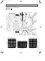
SPLIT-TYPE, HEAT PUMP AIR CONDITIONERS
No. OB230
REVISED EDITION-A
SERVICE MANUAL
Wireless type
Models
MSZ-A09RV MSZ-A12RV -
MUZ-A09RV MUZ-A12RV -
E1
(WH)●
E1
E1
(WH)●
E1
CONTENTS
1. TECHNICAL CHANGES ···································2
2. PART NAMES AND FUNCTIONS······················4
3. SPECIFICATION·················································6
4. NOISE CRITERIA CURVES ·······························8
5. OUTLINES AND DIMENSIONS ·························9
6. WIRING DIAGRAM ··········································10
7. REFRIGERANT SYSTEM DIAGRAM ··············12
8. PERFORMANCE CURVES ······························13
9. MICROPROCESSOR CONTROL ····················23
10. SERVICE FUNCTIONS·····································38
11. TROUBLESHOOTING ······································40
12. DISASSEMBLY INSTRUCTIONS·····················57
13. PARTS LIST······················································61
Revision:
● A number of drainage holes of MUZ-A09RV- E1 and MUZ-A12RV- E1 has been increased.
● Compressors of MUZ-A09RV- E1 and MUZ-A12RV- E1 has been changed.(SNB092FBA ➔ SNB092FJAH)
● SPECIFICATION, OUTLINES AND DIMENSIONS and PARTS LIST have been partially modified.
● Please void OB230.
OB230-1.qxp
02.5.28 7:36 PM
1
Page 2
TECHNICAL CHANGES
INFORMATION FOR THE AIR CONDITIONER WITH R410A REFRIGERANT
• This room air conditioner adopts R410A of HFC refrigerant which never destroys the ozone layer.
Pay attention following points.
1 As R410A working pressure is 1.6 times higher than that of R22 of previous refrigerant, dedicated tools and piping are
required.
2 R410A is more affected by water and contaminations than R22. Keep R410A away from water and contaminations during
storage and while installing.
3 Use clean dedicated piping materials for R410A only which are strong enough against R410A pressure. Never use any
current pipes designed for R22.
4 Composition change may occur in R410A since it is a mixed refrigerant. When charging, charge liquid refrigerant to prevent
composition change.
New refrigerant
Previous refrigerant
R410A
R22
Refrigerant
Composition (Ratio)
HFC-32: HFC-125 (50%:50%)
R22 (100%)
Refrigerant handling
Pseudo-azeotropic refrigerant
Single refrigerant
Not included
Included
Chlorine
A1/A1
A1
72.6
86.5
Boiling point (:)
-51.4
-40.8
Steam pressure [25:](Mpa)
1.557
0.94
Refrigerant
Safety group (ASHRAE)
Molecular weight
64
44.4
Non combustible
Non combustible
ODP w1
0
0.055
GWP w2
1730
1700
From liquid phase in cylinder
Gas phase
Possible
Possible
Kind
Incompatible oil
Compatible oil
Color
Non
Light yellow
Non
Non
Saturated steam density [25:](Kg/K)
Combustibility
Refrigerant charge method
Lubricant
Additional charge on leakage
Smell
w1 :Ozone Destruction Parameter : based on CFC-11
w2 :Global Warmth Parameter
: based on CO2
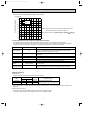
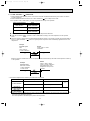
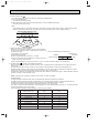
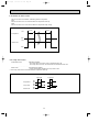
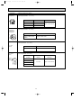
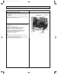
Compressor
New Specification
Current Specification
The incompatible lubricant easily separates from refrigerant
and is in the upper layer inside the suction muffler.
Raising position of the oil back hole enables to back the
lubricant of the upper layer to the compressor.
Since refrigerant and lubricant are compatible each, lubricant
backs to the compressor through the lower position oil back
hole.
Suction muffler
Suction muffler
Compressor
Oil back hole
Compressor
Lubricant
Oil back hole
Lubricant /Refrigerant
Refrigerant
NOTE : The unit of pressure has been changed to MPa on the international system of units(SI unit system).
f [Gauge])
The conversion factor is: 1(MPa [Gauge]) =10.2(kgf/f
2
02.5.28 7:36 PM
Page 3
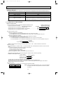
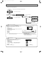
Conversion chart of refrigerant temperature and pressure
(MPa [Gauge])
4.0
Saturated liquid pressure
OB230-1.qxp
3.5
R410A
3.0
R22
2.5
2.0
NOTE : The unit of pressure has been changed to MPa on the
international system of units(SI unit system).
1.5
1.0
f [Gauge])
The conversion factor is: 1(MPa [Gauge]) =10.2(kgf/f
0.5
0.0
-0.5
-30 -20 -10
0
10
20
30
40
50
60
(;)
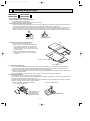
1.Tools dedicated for the air conditioner with R410A refrigerant
The following tools are required for R410A refrigerant. Some R22 tools can be substituted for R410A tools.
The diameter of the service port on the outdoor unit operation valve has been changed to prevent improper refrigerant
charging. Cap size has also been changed from 7/16 UNF with 20 threads to 1/2 UNF with 20 threads.
R410A tools
Description
Can R22 tools be used?
Gauge manifold
No
Charge hose
No
Gas leak detector
No
Torque wrench
Yes
Flare tool
Yes
Flare gauge
Vacuum pump
adapter
Electronic scale for
refrigerant charging
R410A pressures beyonds the measurement range of R22
gauges. Port diameters have been changed to prevent other kinds of
refrigerant from being charged into the units.
Hose material and cap size have been changed to improve the pressure
resistance.
Dedicated for HFC refrigerant.
1/4 and 3/8 wrenches can be used for both R22 and R410A units.
Clamp bar hole has been enlarged to reinforce the spring strength in the tool.
Newly required
Newly required
Newly required
No : Not Substitutable for R410A
Provided for flaring work (to be used with R22 flare tool).
Provided to prevent the back flow of oil. This adapter enables you to use
vacuum pumps.
It is difficult to measure R410A with a charging cylinder because the
refrigerant bubbles due to high pressure and high-speed vaporization
Yes : Substitutable for R410A
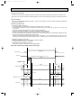
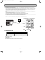
2.Refrigerant piping
1 Specifications
Use the refrigerant pipes that meet the following specifications.
Outside diameter
mm
inch
Wall
thickness
For liquid
6.35
1/4
0.8 mm
Heat resisting foam plastic
For gas
9.52
3/8
0.8 mm
Specific gravity 0.045 Thickness 8 mm
Pipe
Insulation material
• Use a copper pipe or a copper-alloy seamless pipe with a thickness of 0.7 mm or less, as the pressure resistance is in
sufficient.
2 Flaring work and flare nut
Flaring work for R410A pipes differs from that for the existing refrigerant pipes.
For details of flaring work, refer to Installation manual “6-1 FLARING WORK”.
3
OB230-1.qxp
02.5.28 7:36 PM
Page 4
3 Optional extension pipe for R410A
3m
5m
7m
10m
12m
([6.35/[9.52)
([6.35/[9.52)
([6.35/[9.52)
([6.35/[9.52)
([6.35/[9.52)
MAC-A00PI
MAC-A01PI
MAC-A02PI
MAC-A03PI
MAC-A04PI
3.Refrigerant oil
Apply the special refrigeration oil (accessories) to the flare and the union seat surfaces.
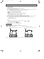
4.Air purge
Use the vacuum pump for air purging for the purpose of environmental protection.
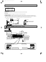
5.Additional charge
For additional charging, charge the refrigerant from liquid phase of the gas cylinder. If the refrigerant is charged from the
gas phase, composition change may occur in the refrigerant inside the cylinder and the outdoor unit. However, charging the
liquid refrigerant all at once may cause the compressor to be locked. Thus, charge the refrigerant slowly.
Gas cylinder
Outdoor unit
Valve
Refrigerant gas cylinder
for R410A with siphon
Liquid
Electronic scale for refrigerant charging
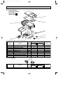
2
PART NAMES AND FUNCTIONS
MSZ-A09RV- E1
MSZ-A12RV- E1
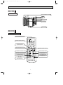
INDOOR UNIT
Grille
Air cleaning
filter(white bellows
type)
Air inlet
Deodorizing filter
(gray sponge type)
to Breaker
Air filter
Power supply cord
Front panel
Remote control
receiving section
Vertical vanes
Horizontal vane
Remote
controller
Operation section
Display section
(When the grille is opened)
Power monitor lamp
Emergency operation switch
Receiving section
4
OB230-1.qxp
02.5.28 7:36 PM
Page 5
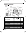
MUZ-A09RV- E1
MUZ-A12RV- E1
OUTDOOR UNIT
Air inlet (back and side)
Piping
Drain hose
Air outlet
Drain outlet
MSZ-A09RV- E1
MSZ-A12RV- E1
REMOTE CONTROLLER
Signal transmitting section
Operation display section
AM
PM
CLOCK
6 00 1 1 00
OPERATE /STOP
(ON /OFF)button
ON/OFF
TOO
WARM
TOO
COOL
OPERATION SELECT button
TEMPERATURE buttons
MODE I FEEL COOL DRY HEAT
FAN
VANE
ECONO COOL
SWING
START
STOP
FAN SPEED CONTROL button
VANE CONTROL button
ECONO COOL button
ON-TIMER button
CLOCK SET button
SWING button
OFF-TIMER button
HR. CLOCK MIN.
HR. button
MIN. button
(TIME SET button)
RESET
5
RESET button
OB230-1.qxp
3
02.5.28 7:36 PM
Page 6
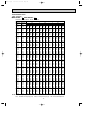
SPECIFICATION
Indoor model
Function
MSZ-A09RV - E1
Heating
Cooling
MSZ-A12RV - E1
Heating
Cooling
Power supply
Single phase
220-240V,50Hz
3.6 (0.9-4.8)
2.6 (0.9-3.3)
540
516
—
1.2
Single phase
220-240V,50Hz
4.8 (0.9-6.1)
3.4 (0.9-3.8)
642
588
—
1.6
10
10
7.25 - 6.65
5.60 - 5.13
1220 (250 - 1580) 1580 (250 - 2050)
kW
Capacity
K /h
Air flow(High)
R/h
Dehumidification
A
Power outlet
A
Running current
W
Power input
A(kW)
Auxiliary heater
%
Power factor
A
Starting current
A
Fan motor current
Model
Winding
"
resistance(at20:)
mm
Dimensions WOHOD
kg
Weight
Air direction
dB
Sound level (High)
rpm
Fan speed (High)
Fan speed regulator
k"
RT11(at25:)
k"
Thermistor RT12(at25:)
k"
RT13(at25:)
Outdoor model
Capacity Outdoor air flow
K /h
A
Electrical Compressor motor current
data
A
Fan motor current
Coefficient of performance(C.O.P)
Model
W
Output
Winding
"
resistance(at20:)
Model
Winding
"
resistance(at20:)
mm
Dimensions WOHOD
kg
Weight
dB
Sound level
rpm
Fan speed
Fan speed regulator
Refrigerant filling
kg
capacity(R410A)
cc
Refrigerating oil (Model)
k"
RT61(at100:)
k"
Thermistor RT62(at0:)
k"
RT64(at50:)
Special
remarks
Fan
motor
Compressor
Special
remarks
Fan
motor
Electrical
data
Capacity
NOTE : Test conditions.
Cooling : Indoor
Outdoor
Heating : Indoor
Outdoor
DB27:
DB35:
DB 20:
DB 7:
4.55-4.17
990 (250-1650)
3.67-3.37
800 (250-1180)
—
99
4.55 - 4.17
0.17
RC4V19-BA
WHT-BLK 292.4
BLK-RED 324.6
850O278O191
10
5
—
99
7.25 - 6.65
0.19
RC4V19-BA
WHT-BLK 292.4
BLK-RED 324.6
850O278O191
10
5
35
950
36
920
3
10
10
10
MUZ-A09RV 1440
6.9
1530
7.4
3
10
10
10
MUZ-A12RV 1440
7.4
3.64
2.79
E1
0.27-0.25
3.25
39
1100
39
1020
E1
1530
8.1
0.27-0.25
3.04
SNB092FJAH
700
U-V 0.93
U-W 0.93
V-W 0.93
RA6V28-CA
WHT-BLK 197
BLK-RED 315 YLW-BLK 13
710(+69)o540o255
34
47
45
700
670
SNB092FJAH
900
U-V 0.93
U-W 0.93
V-W 0.93
RA6V28-CA
WHT-BLK 197
BLK-RED 315 YLW-BLK 13
710(+69)o540o255
34
48
46
700
670
2
2
1.10
1.10
450 (NEO22)
13.4
32.6
17
WB19:
WB24:
WB -:
WB 6:
6
450 (NEO22)
13.4
32.6
17
OB230-1.qxp
02.5.28 7:36 PM
Page 7
Specifications and rating conditions of main electric parts
INDOOR UNIT
MSZ-A09RV
Model
Item
MSZ-A12RV
1.5+ 440V
Indoor fan capacitor
MP24GA 12V 300"
Vane motor
Varistor
ERZV10D471
(NR11)
S201DH1Y
Semiconductor relay
4P
Terminal block
Relay (compressor)
JM1aN-ZTMP-DC12V
(52C)
Terminal block thermal Fuse
93.5:5A 250V
Indoor fan motor thermal fuse
136:i3: 2A
Fuse
250V 3.15A
(F11)
OUTDOOR UNIT
MUZ-A09RV
Model
Item
MUZ-A12RV
Smoothing capacitor
(C61,C62)
500+ 450V
(C65)
1.8+ 440V
Outdoor fan capacitor
Current transformer
Fuse
RR-18
(CT61)
250V 2A
(F801, F901)
Reactor
13A 1.0mH
(L64)
Noise filter
EM43240
Current detecting resistor (R61, 62, 64)
50m" 5W
Current limiting resistor
100" 20W
(R65)
4P
Terminal block
PS21101-AL / PS21204-A
Intelligent power module
Relay
(X61)
G4U-1-E
Relay
(X62)
G4U-1-E
LB6 250V AC
R.V. coil
PMA10001
Power factor controll module
G4A-1A-P-PS
Rush current limiting relay
7
4
02.5.28 7:36 PM
NOISE CRITERIA CURVES
MSZ-A09RV- E1
OCTAVE BAND SOUND PRESSURE LEVEL, dB re 0.0002 MICRO BAR
Page 8
MSZ-A12RV- E1
SPL(dB(A))
HEATING
35
HEATING
COOLING
36
COOLING
Test conditions.
Cooling : DB27:
Heating : DB20:
90
LINE
WB19:
WB -:
80
70
NC-70
60
NC-60
50
NC-50
40
NC-40
30
NC-30
20
10
APPROXIMATE
TERESHOLD OF
HEARING FOR
CONTINUOUS
NOISE
NC-20
125
250
500
1000
2000
4000
NC-70
60
NC-60
50
NC-50
40
NC-40
30
NC-30
20
8000
APPROXIMATE
TERESHOLD OF
HEARING FOR
CONTINUOUS
NOISE
63
2000
4000
NOTCH
SPL(dB(A))
48
COOLING
45
COOLING
46
WB24:
WB 6:
OCTAVE BAND SOUND PRESSURE LEVEL, dB re 0.0002 MICRO BAR
OCTAVE BAND SOUND PRESSURE LEVEL, dB re 0.0002 MICRO BAR
1000
HEATING
60
NC-60
50
NC-50
40
NC-40
30
NC-30
NC-20
500
1000
2000
4000
8000
Test conditions.
Cooling :DB35:
Heating :DB 7:
90
8000
8
WB24:
WB 6:
70
NC-70
60
NC-60
50
NC-50
40
NC-40
30
NC-30
20
APPROXIMATE
TERESHOLD OF
HEARING FOR
CONTINUOUS
NOISE
63
125
NC-20
250
500
1000
2000
4000
BAND CENTER FREQUENCIES, Hz
BAND CENTER FREQUENCIES, Hz
LINE
80
10
250
500
47
NC-70
125
250
MUZ-A12RV- E1
LINE
70
63
125
BAND CENTER FREQUENCIES, Hz
80
10
NC-20
HEATING
APPROXIMATE
TERESHOLD OF
HEARING FOR
CONTINUOUS
NOISE
WB19:
WB -:
70
SPL(dB(A))
90
20
39
NOTCH
Test conditions.
Cooling :DB35:
Heating :DB 7:
LINE
80
BAND CENTER FREQUENCIES, Hz
MUZ-A09RV- E1
SPL(dB(A))
Test conditions.
Cooling : DB27:
Heating : DB20:
90
10
63
NOTCH
NOTCH
OCTAVE BAND SOUND PRESSURE LEVEL, dB re 0.0002 MICRO BAR
OB230-1.qxp
8000
02.5.28 7:36 PM
OUTLINES AND DIMENSIONS
MSZ-A09RV- E1
MSZ-A12RV- E1
82
169
4.5
5
Page 9
Installation plate
231.5
INDOOR UNIT
Indoor unit
271
OB230-1.qxp
81.5
326
42
2.5
41
818
116.5
326
Wall hole [65
5
850
629
{
100
Air in
56
Installation plate
7 or more
278
189
165
Drain hose [16
(Connected part O.D)
Insulation [28
67
17.5
78
Air out
Power supply cord
Lead to right 1.0m
Lead to left 0.3m
160
56
Liquid line [6.35-0.5m
Gas line [9.52-0.43m
Insulation [37 O.D
[21 I.D
MUZ-A09RV- E1
MUZ-A12RV- E1
REQUIRED SPACE
OUTDOOR UNIT
495
100
32.4
Air in
255
127
92
35.4
265
Drainage hole [28
Drainage hole [28
Drainage hole [28
285
320
367
Air in
Drainage hole [28
100mm or more
Wireless remote controller
mm
If a front side or both sides
is vacant. an upper side of
a unit has only to be vacant
100mm.
ore
mm
100
or m
or m
ore
If both sides or back
side is vacant. only
to be free 500mm in
front of a unit
350
re
0mm
o
or m
50
4 holes 10o21
40
Air out
32.5
33
Service panel
20
18
Liquid refrigerant pipe joint
Refrigerant pipe (flared) [6.35
155
90
270
10
3543-
540
Handle
105
69
265
138
500
Service port
Bolt pitch for installation
710
9
Gas refrigerant pipe joint
Refrigerant pipe (flared) [9.52
mm
or m
ore
OB230-1.qxp
02.5.28 7:36 PM
6
Page 10
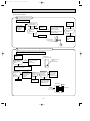
WIRING DIAGRAM
MSZ-A09RV-
MSZ-A12RV-
E1
MODELS WIRING DIAGRAM
E1
INDOOR UNIT
TO OUTDOOR
UNIT
CONNECTING
12V
L
TB
BRN
HIC1
BRN
3
BLU
1
BLU
2
WHT
N
3
CN201
3
2
1
BLU
BLU
GRN/YLW
GRN/YLW
POWER
SUPPLY
CORD
~/N 220-240V
50Hz
4
TRANS
CN
1J1
F11
LD101T
CN
151
10
C11
SR141
GREEN SIGN
MONITOR
MV1
MV2
NAME
RECEIVER
P.C.BOARD
C11
INDOOR FAN CAPACITOR
F11
FUSE (3.15A)
F12
THERMAL FUSE (93:)
HIC1
DC/DC CONVERTER
MF
INDOOR FAN MOTOR
MV1
VANE MOTOR (HORIZONTAL)
MV2
VANE MOTOR (VERTICAL)
NR11
RT11
RT12
NAME
NAME
VARISTOR
SR141
SOLID STATE RELAY
ROOM TEMPERATURE
TB
TERMINAL BLOCK
THERMISTOR
52C
CONTACTOR
INDOOR COIL
THERMISTOR (MAIN)
RT13
SYMBOL
INDOOR COIL
THERMISTOR (SUB)
NOTE:1. About the outdoor side electric wiring refer to the outdoor unit electric wiring diagram for servicing.
2. Use copper conductors only. (For field wiring)
3. Symbols below indicate.
/: Terminal block,
: Connector
10
1
2
3
MF
4
5
6
RT11
REMOTE
CONTROLLER
SYMBOL
YLW
RED
5
CIRCUIT BREAKER
GRY
WHT
CN211
CN
ELECTRONIC CONTROL P.C. BOARD 111
P.C.BOARD
BLK
BRN
1
2
3
POWER MONITOR,
PE
SYMBOL
RT12
CN112
3
CN
121
NR11
52C
BLU
11
RT13
1
RED
F12
220-240V~ 2
4
3
2
02.5.28 7:36 PM
MUZ-A09RV-
Page 11
E1
MUZ-A12RV-
MODELS WIRING DIAGRAM
E1
OUTDOOR UNIT
~
TB2
CN
911
3
2
1
X61
X62
1 2 3 4 5 6
21S4
C61
+
C62
+
U
F801
P
TRANS
R64
N
ELECTRONIC
CONTROL
P.C BOARD
5
CN601
1 2 3
MF61
GRY
1
2
TAB76 BLK
CN912
3
2
1
TAB75 GRY
L64
R62
IC950
BLU
+
LEV
GRN/YLW
6
5
4
3
2
1
LD65
BLK
LD66
V
LD67
W
IPM
1
2
BLK
WHT
RED
2
3
RT64
1
BLK
TAB71
-
R61
6
WHT
BLU
~
CN642
N
2 1
LD61
CN641
WHT
RELAY
P.C
BOARD
ORG
WHT
BLK
RED
YLW
TB1
3
RED
220-240V ~ 2
4
F901
CN913
TAB62
TAB61
12V
WHT
C65
L61
SSR61
TAB72
CT61
LD-E
DSA61
GRN
BLU
4
PFC
RED
LDNF1
LDNF2
BLU
CN914
X64
R65
TAB69
LD62
CN724
WHT
CN778 CN779
TAB68
CN726
L63
CN771
NOISE FILTER P.C BOARD
NR61
OB230-1.qxp
RT61
W
RT62
V
MC
FROM INDOOR UNIT
CONNECTING
U
SYMBOL
CT61
NAME
CURRENT TRANSFORMER
C61,C62 SMOOTHING CAPACITOR
SYMBOL
NAME
SYMBOL
NAME
L63
COIL
R64
CURRENT-DETECTING RESISTOR
L64
REACTOR
R65
CURRENT-LIMITING RESISTOR
COMPRESSOR
SSR61
SOLID STATE RELAY
C65
OUTDOOR FAN CAPACITOR MC
DSA61
SURGE ABSORBER
MF61
OUTDOOR FAN MOTOR (INNER FUSE) TB1, TB2 TERMINAL BLOCK
F801
FUSE (2A)
NR61
VARISTOR
F901
FUSE (2A)
PFC
POWER FACTOR CONTROL MODULE X64
IC950
DC/DC CONVERTER
RT61
DISCHARGE TEMPERATURE THERMISTOR
IPM
INTELLIGENT POWER MODULE RT62
LEV
EXPANSION VALVE COIL
RT64
FIN TEMPERATURE THERMISTOR
L61
CMC COIL
R61,62
CURRENT-DETECTING RESISTOR
DEFROST THERMISTOR
NOTE:1. About the indoor side electric wiring refer to the indoor unit electric wiring diagram for servicing.
2.Use copper conductors only. (For field wiring)
3. Symbols below indicate.
/: Terminal block,
: Connector
11
X61, X62 RELAY
21S4
RELAY
R.V. COIL
(COOLING TURN ON)
OB230-1.qxp
7
02.5.28 7:36 PM
Page 12
REFRIGERANT SYSTEM DIAGRAM
Unit : mm
MSZ-A09RV - E1
MSZ-A12RV - E1
MUZ-A09RV - E1
MUZ-A12RV - E1
4-way valve
INDOOR UNIT
Refrigerant pipe [9.52
(Option)
Indoor
heat
exchanger
Indoor coil
thermistor
RT12(main)
Distributor
OUTDOOR UNIT
Muffler
Stop valve
(with service port)
Flared connection
Discharge
thermistor
RT61
Indoor coil
thermistor
RT13(sub)
Outdoor
heat
exchanger
Maffler
Compressor
Defrost
thermistor
RT62
Room temperature
thermistor
RT11
Accumulator
Capillary tube
(2 pcs)
[3.0o[2.0o300
Expansion
valve
Flared connection
Capillary tube
[3.0o[2.0o200
Stop valve
Refrigerant pipe [6.35
(Option)
Refrigerant flow in cooling
Refrigerant flow in heating
MAX. REFRIGERANT PIPING LENGTH
Model
Additional piping
Max. length :mm
A
Gas
Liquid
MSZ-A09RV- E1
MSZ-A12RV- E1
12
9.52
6.35
Piping size O.D : mm
Length of connecting pipe : m
Indoor unit
Outdoor unit
Liquid: 0.5
Gas : 0.43
0
MAX. HEIGHT DIFFERENCE
Indoor
unit
Height difference should be within
w Max. Height
5m regardless of which unit,
difference 8m
indoor or outdoor position is high.
Refrigerant Piping
Max. length
A
Outdoor unit
ADDITIONAL REFRIGERANT CHARGE (R410A:g)
Model
Outdoor unit precharged
MSZ-A09RV- E1
MSZ-A12RV- E1
1100
Refrigerant piping length (one way)
7m
8m
9m
10m
11m
12m
0
30
60
90
120
150
Calculation : Xg=30g /m✕ (A-7)m
For additional charging, charge the refrigerant from liquid phase of the gas cylinder.
If the refrigerant inside the cylinder and the outdoor unit.
However, charging the liquid refrigerant all at once may cause the compressor to be locked.
Thus, charge the refrigerant slowly.
12
OB230-1.qxp
02.5.28 7:36 PM
8
Page 13
PERFORMANCE CURVES
MSZ-A09RV - E1 MUZ-A12RV - E1
MSZ-A12RV - E1 MUZ-A12RV - E1
The standard data contained in these specifications apply only to the operation of the air conditioner under normal conditions.
Since operating conditions vary according to the areas where these units are installed. The following information has been
provided to clarify the operating characteristics of the air conditioner under the conditions indicated by the performance curve.
(1) GUARANTEED VOLTAGE
198 ~ 264V, 50Hz
(2) AIR FLOW
Air flow should be set at MAX.
(3) MAIN READINGS
(1) Indoor intake air wet-bulb temperature
(2) Indoor discharge air wet-bulb temperature
(3) Outdoor intake air dry-bulb temperature
(4) Total input
(5) Indoor intake air dry-bulb temperature
(6) Outdoor intake air wet-bulb temperature
(7) Total input
::WB
::WB
::DB
:W
::DB
::WB
:W
}
}
Cooling
Heating
Indoor air wet-bulb temperature difference on the left side of the chart on page 14 and 15 shows the difference between
the indoor intake air wet-bulb temperature and the indoor discharge air wet-bulb temperature for your reference at service.
How to measure the indoor air wet-bulb temperature difference
1.
2.
3.
4.
5.
6.
7.
Attach at least 2 sets of wet-and dry-bulb thermometers to the indoor air intake as shown in the figure, and at least 2 sets
of wet-and dry-bulb thermometers to the indoor air outlet. The thermometers must be attached to the position where air
speed is high.
Attach at least 2 sets of dry-bulb thermometers to the outdoor air intake.
Cover the thermometers to prevent direct rays of the sun.
Check that the air filter is cleaned.
Open windows and doors of room.
Press the EMERGENCY OPERATION switch once (twice) to start the EMERGENCY COOL (HEAT) MODE.
When system stabilizes after more than 15 minutes, measure temperature and take an average temperature.
10 minutes later, measure temperature again and check that the temperature does not change.
OUTDOOR UNIT
INDOOR UNIT
13
OB230-1.qxp
02.5.28 7:36 PM
Page 14
7.4
8.5
6.9
7.9
6.3
7.3
5.8
6.7
5.3
6.1
4.8
5.5
MSZ-A09RV- E1
MSZ-A12RV- E1
Cooling capacity
MUZ-A09RV - E1
MUZ-A09RV - E1
Correction of Cooling capacity
Correction of total input
2.0
Capacity correction factors
Capacity correction factors
1.5
1.0
0.5
0.0
0
50
100
150(Hz)
1.5
1.0
0.5
0
The operational frequency of compressor
150(Hz)
MUZ-A12RV - E1
Correction of Cooling capacity
Correction of total input
1.5
2.0
Capacity correction factors
Capacity correction factors
100
The operational frequency of compressor
MUZ-A12RV - E1
1.0
0.5
0.0
0
50
50
100
150(Hz)
The operational frequency of compressor
1.5
1.0
0.5
0
50
100
150(Hz)
The operational frequency of compressor
14
02.5.28 7:36 PM
Page 15
Heating capacity
23.4
18.8
21.1
16.7
18.7
14.6
16.4
12.5
14.1
MUZ-A09RV - E1
MUZ-A09RV - E1
Correction of Heating capacity
Correction of total input
1.5
1.5
Capacity correction factors
25.8
20.9
1.0
0.5
0.0
0
50
100
150(Hz)
1.0
0.5
0
The operational frequency of compressor
MUZ-A12RV - E1
100
150(Hz)
MUZ-A12RV - E1
Correction of Heating capacity
Correction of total input
1.5
1.5
1.0
0.5
0.0
0
50
The operational frequency of compressor
Capacity correction factors
28.1
23.0
Capacity correction factors
30.4
25.1
Capacity correction factors
27.1
MSZ-A12RV- E1
NOTE:The above curves are for the heating operation without any frost.
MSZ-A09RV- E1
OB230-1.qxp
50
100
150(Hz)
The operational frequency of compressor
1.0
0.5
0
50
100
150(Hz)
The operational frequency of compressor
15
OB230-1.qxp
02.5.28 7:36 PM
Page 16
OUTDOOR LOW PRESSURE AND OUTDOOR UNIT CURRENT
How to operate with fixed operational frequency of the compressor.
1. Press the EMERGENCY OPERATION switch on the front of the indoor unit , and select either the COOL mode or the
HEAT mode before starting to operate the air conditioner.
2. The compressor starts up.
The operational frequency of the compressor is 83Hz in the COOL mode and 58Hz in the HEAT mode.
3. The fan speed of the indoor unit is High.
4. This operation continues for 30minutes.
5. In order to release this operation, press the EMERGENCY OPERATION switch again, press any button on the remote
controller.
NOTE : The unit of pressure has been changed to MPa on the international system of units(SI unit system).
f [Gauge])
The conversion factor is: 1(MPa [Gauge]) =10.2(kgf/f
COOL operation
1 Both indoor and outdoor unit are under the same temperature/humidity condition.
Dry-bulb temperature
Relative
20
25
30
2 Air flow should be set at High.
humidity(%)
50
60
70
3 Operational frequency : 83Hz
MUZ-A09RV - E1
MUZ-A09RV - E1
(Reference)
(kgf/F [Gauge]) (MPa [Gauge])
12
11
10
9
8
7
5
1.3
62Hz
Outdoor unit current (A)
Outdoor low pressure
13
1.2
1.1
1.0
0.9
0.8
0.7
15
18 20
50
25
60
30 32
70(%)
4
240V
3
2
1
15
35(:
Ambient temperature(:)
Ambient humidity(%)
9
8
7
6
1.2
Outdoor unit current (A)
Outdoor low pressure
10
30 32
70(%)
25
60
35(:)
MUZ-A12RV - E1
MUZ-A12RV - E1
11
18 20
50
Ambient temperature(:)
Ambient humidity(%)
(Reference)
(kgf/F [Gauge]) (MPa [Gauge])
12
53Hz
220V
62Hz
62Hz
1.1
1.0
0.9
0.8
7
220V
6
83Hz
240V
5
4
0.7
0.6
15
18 20
50
25
60
30 32
70(%)
3
15
35(:
Ambient temperature(:)
Ambient humidity(%)
18 20
50
25
60
30 32 35(:)
70(%)
Ambient temperature(:)
Ambient humidity(%)
16
02.5.28 7:36 PM
Page 17
HEAT operation
Condition Indoor : Dry bulb temperature 20.0:
Wet bulb temperature 14.5:
Outdoor : Dry bulb temperature 2 7 15 20.0:
Wet bulb temperature 1 6 12 14.5:
MUZ-A12RV - E1
MUZ-A09RV - E1
6.0
5.5
220V
5.0
58Hz
4.5
240V
4.0
3.5
3.0
2
5
10
15
20
25
Outdoor unit current (A)
6.0
Outdoor unit current (A)
OB230-1.qxp
5.5
5.0
220V
58Hz
4.5
240V
4.0
3.5
3.0
Ambient temperature(:)
2
5
10
15
20
Ambient temperature(:)
17
25
OB230-1.qxp
02.5.28 7:36 PM
Page 18
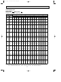
PERFORMANCE DATA
COOL operation
MSZ-A09RV - E1 MUZ-A09RV - E1
CAPACITY : 2.6 kW INPUT : 800 W SHF : 0.74
OUTDOOR DB(:)
INDOOR INDOOR
21
25
27
30
DB(:) WB(:)
Q SHC SHF INPUT Q SHC SHF INPUT Q SHC SHF INPUT Q SHC SHF INPUT
21
18
3.06 1.71 0.56 640 2.93 1.64 0.56 672 2.81 1.57 0.56 704 2.70 1.51 0.56 736
21
20
3.19 1.40 0.44 672 3.06 1.34 0.44 712 2.96 1.30 0.44 728 2.86 1.26 0.44 760
22
18
3.06 1.83 0.60 640 2.93 1.76 0.60 672 2.81 1.68 0.60 704 2.70 1.62 0.60 736
22
20
3.19 1.53 0.48 672 3.06 1.47 0.48 712 2.96 1.42 0.48 728 2.86 1.37 0.48 760
22
22
3.32 1.19 0.36 696 3.20 1.15 0.36 740 3.12 1.12 0.36 760 2.99 1.08 0.36 792
23
18
3.06 1.96 0.64 640 2.93 1.87 0.64 672 2.81 1.80 0.64 704 2.70 1.73 0.64 736
23
20
3.19 1.66 0.52 672 3.06 1.59 0.52 712 2.96 1.54 0.52 728 2.86 1.49 0.52 760
23
22
3.32 1.33 0.40 696 3.20 1.28 0.40 740 3.12 1.25 0.40 760 2.99 1.20 0.40 792
24
18
3.06 2.08 0.68 640 2.93 1.99 0.68 672 2.81 1.91 0.68 704 2.70 1.84 0.68 736
24
20
3.19 1.78 0.56 672 3.06 1.71 0.56 712 2.96 1.66 0.56 728 2.86 1.60 0.56 760
24
22
3.32 1.46 0.44 696 3.20 1.41 0.44 740 3.12 1.37 0.44 760 2.99 1.32 0.44 792
24
24
3.48 1.11 0.32 728 3.35 1.07 0.32 768 3.28 1.05 0.32 792 3.17 1.02 0.32 832
25
18
3.06 2.20 0.72 640 2.93 2.11 0.72 672 2.81 2.02 0.72 704 2.70 1.95 0.72 736
25
20
3.19 1.91 0.60 672 3.06 1.83 0.60 712 2.96 1.78 0.60 728 2.86 1.72 0.60 760
25
22
3.32 1.59 0.48 696 3.20 1.54 0.48 740 3.12 1.50 0.48 760 2.99 1.44 0.48 792
25
24
3.48 1.25 0.36 728 3.35 1.21 0.36 768 3.28 1.18 0.36 792 3.17 1.14 0.36 832
26
18
3.06 2.32 0.76 640 2.93 2.22 0.76 672 2.81 2.13 0.76 704 2.70 2.06 0.76 736
26
20
3.19 2.04 0.64 672 3.06 1.96 0.64 712 2.96 1.90 0.64 728 2.86 1.83 0.64 760
26
22
3.32 1.72 0.52 696 3.20 1.66 0.52 740 3.12 1.62 0.52 760 2.99 1.55 0.52 792
26
24
3.48 1.39 0.40 728 3.35 1.34 0.40 768 3.28 1.31 0.40 792 3.17 1.27 0.40 832
26
26
3.59 1.00 0.28 768 3.48 0.98 0.28 808 3.43 0.96 0.28 832 3.33 0.93 0.28 856
27
18
3.06 2.44 0.80 640 2.93 2.34 0.80 672 2.81 2.25 0.80 704 2.70 2.16 0.80 736
27
20
3.19 2.17 0.68 672 3.06 2.08 0.68 712 2.96 2.02 0.68 728 2.86 1.94 0.68 760
27
22
3.32 1.86 0.56 696 3.20 1.79 0.56 740 3.12 1.75 0.56 760 2.99 1.67 0.56 792
27
24
3.48 1.53 0.44 728 3.35 1.48 0.44 768 3.28 1.44 0.44 792 3.17 1.40 0.44 832
27
26
3.59 1.15 0.32 768 3.48 1.11 0.32 808 3.43 1.10 0.32 832 3.33 1.06 0.32 856
28
18
3.06 2.57 0.84 640 2.93 2.46 0.84 672 2.81 2.36 0.84 704 2.70 2.27 0.84 736
28
20
3.19 2.29 0.72 672 3.06 2.20 0.72 712 2.96 2.13 0.72 728 2.86 2.06 0.72 760
28
22
3.32 1.99 0.60 696 3.20 1.92 0.60 740 3.12 1.87 0.60 760 2.99 1.79 0.60 792
28
24
3.48 1.67 0.48 728 3.35 1.61 0.48 768 3.28 1.57 0.48 792 3.17 1.52 0.48 832
28
26
3.59 1.29 0.36 768 3.48 1.25 0.36 808 3.43 1.24 0.36 832 3.33 1.20 0.36 856
29
18
3.06 2.69 0.88 640 2.93 2.57 0.88 672 2.81 2.47 0.88 704 2.70 2.38 0.88 736
29
20
3.19 2.42 0.76 672 3.06 2.32 0.76 712 2.96 2.25 0.76 728 2.86 2.17 0.76 760
29
22
3.32 2.12 0.64 696 3.20 2.05 0.64 740 3.12 2.00 0.64 760 2.99 1.91 0.64 792
29
24
3.48 1.81 0.52 728 3.35 1.74 0.52 768 3.28 1.70 0.52 792 3.17 1.65 0.52 832
29
26
3.59 1.44 0.40 768 3.48 1.39 0.40 808 3.43 1.37 0.40 832 3.33 1.33 0.40 856
30
18
3.06 2.81 0.92 640 2.93 2.69 0.92 672 2.81 2.58 0.92 704 2.70 2.49 0.92 736
30
20
3.19 2.55 0.80 672 3.06 2.44 0.80 712 2.96 2.37 0.80 728 2.86 2.29 0.80 760
30
22
3.32 2.25 0.68 696 3.20 2.17 0.68 740 3.12 2.12 0.68 760 2.99 2.03 0.68 792
30
24
3.48 1.95 0.56 728 3.35 1.88 0.56 768 3.28 1.83 0.56 792 3.17 1.78 0.56 832
30
26
3.59 1.58 0.44 768 3.48 1.53 0.44 808 3.43 1.51 0.44 832 3.33 1.46 0.44 856
31
18
3.06 2.93 0.96 640 2.93 2.81 0.96 672 2.81 2.70 0.96 704 2.70 2.60 0.96 736
31
20
3.19 2.68 0.84 672 3.06 2.57 0.84 712 2.96 2.49 0.84 728 2.86 2.40 0.84 760
31
22
3.32 2.39 0.72 696 3.20 2.30 0.72 740 3.12 2.25 0.72 760 2.99 2.15 0.72 792
31
24
3.48 2.09 0.60 728 3.35 2.01 0.60 768 3.28 1.97 0.60 792 3.17 1.90 0.60 832
31
26
3.59 1.72 0.48 768 3.48 1.67 0.48 808 3.43 1.65 0.48 832 3.33 1.60 0.48 856
32
18
3.06 3.06 1.00 640 2.93 2.93 1.00 672 2.81 2.81 1.00 704 2.70 2.70 1.00 736
32
20
3.19 2.80 0.88 672 3.06 2.69 0.88 712 2.96 2.61 0.88 728 2.86 2.52 0.88 760
32
22
3.32 2.52 0.76 696 3.20 2.43 0.76 740 3.12 2.37 0.76 760 2.99 2.27 0.76 792
32
24
3.48 2.23 0.64 728 3.35 2.15 0.64 768 3.28 2.10 0.64 792 3.17 2.03 0.64 832
32
26
3.59 1.87 0.52 768 3.48 1.81 0.52 808 3.43 1.78 0.52 832 3.33 1.73 0.52 856
NOTE
Q : Total capacity (kW)
SHC : Sensible heat capacity (kW)
SHF : Sensible heat factor
INPUT : Total power input (W)
18
DB : Dry-bulb temperature
WB : Wet-bulb temperature
OB230-1.qxp
02.5.28 7:36 PM
Page 19
PERFORMANCE DATA
COOL operation
MSZ-A09RV - E1 MUZ-A09RV - E1
CAPACITY : 2.6 kW INPUT : 800 W SHF : 0.74
OUTDOOR DB(:)
INDOOR INDOOR
35
40
DB(:)
WB(:)
Q SHC SHF INPUT Q SHC SHF INPUT
21
18
2.55 1.43 0.56 784 2.34 1.31 0.56 832
21
20
2.68 1.18 0.44 816 2.50 1.10 0.44 856
22
18
2.55 1.53 0.60 784 2.34 1.40 0.60 832
22
20
2.68 1.29 0.48 816 2.50 1.20 0.48 856
22
22
2.83 1.02 0.36 848 2.65 0.95 0.36 896
23
18
2.55 1.63 0.64 784 2.34 1.50 0.64 832
23
20
2.68 1.39 0.52 816 2.50 1.30 0.52 856
23
22
2.83 1.13 0.40 848 2.65 1.06 0.40 896
24
18
2.55 1.73 0.68 784 2.34 1.59 0.68 832
24
20
2.68 1.50 0.56 816 2.50 1.40 0.56 856
24
22
2.83 1.25 0.44 848 2.65 1.17 0.44 896
24
24
2.99 0.96 0.32 880 2.81 0.90 0.32 920
25
18
2.55 1.83 0.72 784 2.34 1.68 0.72 832
25
20
2.68 1.61 0.60 816 2.50 1.50 0.60 856
25
22
2.83 1.36 0.48 848 2.65 1.27 0.48 896
25
24
2.99 1.08 0.36 880 2.81 1.01 0.36 920
26
18
2.55 1.94 0.76 784 2.34 1.78 0.76 832
26
20
2.68 1.71 0.64 816 2.50 1.60 0.64 856
26
22
2.83 1.47 0.52 848 2.65 1.38 0.52 896
26
24
2.99 1.20 0.40 880 2.81 1.12 0.40 920
26
26
3.15 0.88 0.28 912 2.96 0.83 0.28 952
27
18
2.55 2.04 0.80 784 2.34 1.87 0.80 832
27
20
2.68 1.82 0.68 816 2.50 1.70 0.68 856
27
22
2.83 1.59 0.56 848 2.65 1.49 0.56 896
27
24
2.99 1.32 0.44 880 2.81 1.24 0.44 920
27
26
3.15 1.01 0.32 912 2.96 0.95 0.32 952
28
18
2.55 2.14 0.84 784 2.34 1.97 0.84 832
28
20
2.68 1.93 0.72 816 2.50 1.80 0.72 856
28
22
2.83 1.70 0.60 848 2.65 1.59 0.60 896
28
24
2.99 1.44 0.48 880 2.81 1.35 0.48 920
28
26
3.15 1.13 0.36 912 2.96 1.07 0.36 952
29
18
2.55 2.24 0.88 784 2.34 2.06 0.88 832
29
20
2.68 2.04 0.76 816 2.50 1.90 0.76 856
29
22
2.83 1.81 0.64 848 2.65 1.70 0.64 896
29
24
2.99 1.55 0.52 880 2.81 1.46 0.52 920
29
26
3.15 1.26 0.40 912 2.96 1.19 0.40 952
30
18
2.55 2.34 0.92 784 2.34 2.15 0.92 832
30
20
2.68 2.14 0.80 816 2.50 2.00 0.80 856
30
22
2.83 1.93 0.68 848 2.65 1.80 0.68 896
30
24
2.99 1.67 0.56 880 2.81 1.57 0.56 920
30
26
3.15 1.38 0.44 912 2.96 1.30 0.44 952
31
18
2.55 2.45 0.96 784 2.34 2.25 0.96 832
31
20
2.68 2.25 0.84 816 2.50 2.10 0.84 856
31
22
2.83 2.04 0.72 848 2.65 1.91 0.72 896
31
24
2.99 1.79 0.60 880 2.81 1.68 0.60 920
31
26
3.15 1.51 0.48 912 2.96 1.42 0.48 952
32
18
2.55 2.55 1.00 784 2.34 2.34 1.00 832
32
20
2.68 2.36 0.88 816 2.50 2.20 0.88 856
32
22
2.83 2.15 0.76 848 2.65 2.02 0.76 896
32
24
2.99 1.91 0.64 880 2.81 1.80 0.64 920
32
26
3.15 1.64 0.52 912 2.96 1.54 0.52 952
NOTE
Q : Total capacity (kW)
SHC : Sensible heat capacity (kW)
SHF : Sensible heat factor
INPUT : Total power input (W)
19
Q
2.25
2.41
2.25
2.41
2.56
2.25
2.41
2.56
2.25
2.41
2.56
2.73
2.25
2.41
2.56
2.73
2.25
2.41
2.56
2.73
2.87
2.25
2.41
2.56
2.73
2.87
2.25
2.41
2.56
2.73
2.87
2.25
2.41
2.56
2.73
2.87
2.25
2.41
2.56
2.73
2.87
2.25
2.41
2.56
2.73
2.87
2.25
2.41
2.56
2.73
2.87
SHC
1.26
1.06
1.35
1.15
0.92
1.44
1.25
1.02
1.53
1.35
1.13
0.87
1.62
1.44
1.23
0.98
1.71
1.54
1.33
1.09
0.80
1.80
1.64
1.43
1.20
0.92
1.89
1.73
1.54
1.31
1.03
1.98
1.83
1.64
1.42
1.15
2.07
1.92
1.74
1.53
1.26
2.16
2.02
1.84
1.64
1.38
2.25
2.12
1.95
1.75
1.49
43
SHF INPUT
0.56 848
0.44 880
0.60 848
0.48 880
0.36 912
0.64 848
0.52 880
0.40 912
0.68 848
0.56 880
0.44 912
0.32 940
0.72 848
0.60 880
0.48 912
0.36 940
0.76 848
0.64 880
0.52 912
0.40 940
0.28 972
0.80 848
0.68 880
0.56 912
0.44 940
0.32 972
0.84 848
0.72 880
0.60 912
0.48 940
0.36 972
0.88 848
0.76 880
0.64 912
0.52 940
0.40 972
0.92 848
0.80 880
0.68 912
0.56 940
0.44 972
0.96 848
0.84 880
0.72 912
0.60 940
0.48 972
1.00 848
0.88 880
0.76 912
0.64 940
0.52 972
DB : Dry-bulb temperature
WB : Wet-bulb temperature
OB230-1.qxp
02.5.28 7:36 PM
Page 20
PERFORMANCE DATA
COOL operation
MSZ-A12RV - E1 MUZ-A12RV - E1
CAPACITY : 3.4 kW INPUT : 1220 W SHF : 0.69
OUTDOOR DB(:)
INDOOR INDOOR
21
25
27
30
DB(:) WB(:)
Q SHC SHF INPUT Q SHC SHF INPUT Q SHC SHF INPUT Q SHC SHF INPUT
21
18
4.00 2.04 0.51 976 3.83 1.95 0.51 1025 3.67 1.87 0.51 1074 3.54 1.80 0.51 1122
21
20
4.17 1.62 0.39 1025 4.00 1.56 0.39 1086 3.88 1.51 0.39 1110 3.74 1.46 0.39 1159
22
18
4.00 2.20 0.55 976 3.83 2.10 0.55 1025 3.67 2.02 0.55 1074 3.54 1.94 0.55 1122
22
20
4.17 1.79 0.43 1025 4.00 1.72 0.43 1086 3.88 1.67 0.43 1110 3.74 1.61 0.43 1159
22
22
4.34 1.34 0.31 1061 4.18 1.30 0.31 1129 4.08 1.26 0.31 1159 3.91 1.21 0.31 1208
23
18
4.00 2.36 0.59 976 3.83 2.26 0.59 1025 3.67 2.17 0.59 1074 3.54 2.09 0.59 1122
23
20
4.17 1.96 0.47 1025 4.00 1.88 0.47 1086 3.88 1.82 0.47 1110 3.74 1.76 0.47 1159
23
22
4.34 1.52 0.35 1061 4.18 1.46 0.35 1129 4.08 1.43 0.35 1159 3.91 1.37 0.35 1208
24
18
4.00 2.52 0.63 976 3.83 2.41 0.63 1025 3.67 2.31 0.63 1074 3.54 2.23 0.63 1122
24
20
4.17 2.12 0.51 1025 4.00 2.04 0.51 1086 3.88 1.98 0.51 1110 3.74 1.91 0.51 1159
24
22
4.34 1.69 0.39 1061 4.18 1.63 0.39 1129 4.08 1.59 0.39 1159 3.91 1.52 0.39 1208
24
24
4.56 1.23 0.27 1110 4.39 1.18 0.27 1171 4.28 1.16 0.27 1208 4.15 1.12 0.27 1269
25
18
4.00 2.68 0.67 976 3.83 2.56 0.67 1025 3.67 2.46 0.67 1074 3.54 2.37 0.67 1122
25
20
4.17 2.29 0.55 1025 4.00 2.20 0.55 1086 3.88 2.13 0.55 1110 3.74 2.06 0.55 1159
25
22
4.34 1.86 0.43 1061 4.18 1.80 0.43 1129 4.08 1.75 0.43 1159 3.91 1.68 0.43 1208
25
24
4.56 1.41 0.31 1110 4.39 1.36 0.31 1171 4.28 1.33 0.31 1208 4.15 1.29 0.31 1269
26
18
4.00 2.84 0.71 976 3.83 2.72 0.71 1025 3.67 2.61 0.71 1074 3.54 2.51 0.71 1122
26
20
4.17 2.46 0.59 1025 4.00 2.36 0.59 1086 3.88 2.29 0.59 1110 3.74 2.21 0.59 1159
26
22
4.34 2.04 0.47 1061 4.18 1.97 0.47 1129 4.08 1.92 0.47 1159 3.91 1.84 0.47 1208
26
24
4.56 1.59 0.35 1110 4.39 1.54 0.35 1171 4.28 1.50 0.35 1208 4.15 1.45 0.35 1269
26
26
4.69 1.08 0.23 1171 4.56 1.05 0.23 1232 4.49 1.03 0.23 1269 4.35 1.00 0.23 1305
27
18
4.00 3.00 0.75 976 3.83 2.87 0.75 1025 3.67 2.75 0.75 1074 3.54 2.65 0.75 1122
27
20
4.17 2.62 0.63 1025 4.00 2.52 0.63 1086 3.88 2.44 0.63 1110 3.74 2.36 0.63 1159
27
22
4.34 2.21 0.51 1061 4.18 2.13 0.51 1129 4.08 2.08 0.51 1159 3.91 1.99 0.51 1208
27
24
4.56 1.78 0.39 1110 4.39 1.71 0.39 1171 4.28 1.67 0.39 1208 4.15 1.62 0.39 1269
27
26
4.69 1.27 0.27 1171 4.56 1.23 0.27 1232 4.49 1.21 0.27 1269 4.35 1.18 0.27 1305
28
18
4.00 3.16 0.79 976 3.83 3.02 0.79 1025 3.67 2.90 0.79 1074 3.54 2.79 0.79 1122
28
20
4.17 2.79 0.67 1025 4.00 2.68 0.67 1086 3.88 2.60 0.67 1110 3.74 2.51 0.67 1159
28
22
4.34 2.38 0.55 1061 4.18 2.30 0.55 1129 4.08 2.24 0.55 1159 3.91 2.15 0.55 1208
28
24
4.56 1.96 0.43 1110 4.39 1.89 0.43 1171 4.28 1.84 0.43 1208 4.15 1.78 0.43 1269
28
26
4.69 1.45 0.31 1171 4.56 1.41 0.31 1232 4.49 1.39 0.31 1269 4.35 1.35 0.31 1305
29
18
4.00 3.32 0.83 976 3.83 3.17 0.83 1025 3.67 3.05 0.83 1074 3.54 2.93 0.83 1122
29
20
4.17 2.96 0.71 1025 4.00 2.84 0.71 1086 3.88 2.75 0.71 1110 3.74 2.66 0.71 1159
29
22
4.34 2.56 0.59 1061 4.18 2.47 0.59 1129 4.08 2.41 0.59 1159 3.91 2.31 0.59 1208
29
24
4.56 2.14 0.47 1110 4.39 2.06 0.47 1171 4.28 2.01 0.47 1208 4.15 1.95 0.47 1269
29
26
4.69 1.64 0.35 1171 4.56 1.59 0.35 1232 4.49 1.57 0.35 1269 4.35 1.52 0.35 1305
30
18
4.00 3.48 0.87 976 3.83 3.33 0.87 1025 3.67 3.19 0.87 1074 3.54 3.08 0.87 1122
30
20
4.17 3.12 0.75 1025 4.00 3.00 0.75 1086 3.88 2.91 0.75 1110 3.74 2.81 0.75 1159
30
22
4.34 2.73 0.63 1061 4.18 2.63 0.63 1129 4.08 2.57 0.63 1159 3.91 2.46 0.63 1208
30
24
4.56 2.32 0.51 1110 4.39 2.24 0.51 1171 4.28 2.18 0.51 1208 4.15 2.12 0.51 1269
30
26
4.69 1.83 0.39 1171 4.56 1.78 0.39 1232 4.49 1.75 0.39 1269 4.35 1.70 0.39 1305
31
18
4.00 3.64 0.91 976 3.83 3.48 0.91 1025 3.67 3.34 0.91 1074 3.54 3.22 0.91 1122
31
20
4.17 3.29 0.79 1025 4.00 3.16 0.79 1086 3.88 3.06 0.79 1110 3.74 2.95 0.79 1159
31
22
4.34 2.90 0.67 1061 4.18 2.80 0.67 1129 4.08 2.73 0.67 1159 3.91 2.62 0.67 1208
31
24
4.56 2.51 0.55 1110 4.39 2.41 0.55 1171 4.28 2.36 0.55 1208 4.15 2.28 0.55 1269
31
26
4.69 2.02 0.43 1171 4.56 1.96 0.43 1232 4.49 1.93 0.43 1269 4.35 1.87 0.43 1305
32
18
4.00 3.80 0.95 976 3.83 3.63 0.95 1025 3.67 3.49 0.95 1074 3.54 3.36 0.95 1122
32
20
4.17 3.46 0.83 1025 4.00 3.32 0.83 1086 3.88 3.22 0.83 1110 3.74 3.10 0.83 1159
32
22
4.34 3.08 0.71 1061 4.18 2.97 0.71 1129 4.08 2.90 0.71 1159 3.91 2.78 0.71 1208
32
24
4.56 2.69 0.59 1110 4.39 2.59 0.59 1171 4.28 2.53 0.59 1208 4.15 2.45 0.59 1269
32
26
4.69 2.21 0.47 1171 4.56 2.14 0.47 1232 4.49 2.11 0.47 1269 4.35 2.05 0.47 1305
NOTE
Q : Total capacity (kW)
SHC : Sensible heat capacity (kW)
SHF : Sensible heat factor
INPUT : Total power input (W)
20
DB : Dry-bulb temperature
WB : Wet-bulb temperature
OB230-1.qxp
02.5.28 7:36 PM
Page 21
PERFORMANCE DATA
COOL operation
MSZ-A12RV - E1 MUZ-A12RV - E1
CAPACITY : 3.4 kW INPUT : 1220 W SHF : 0.69
OUTDOOR DB(:)
INDOOR INDOOR
35
40
DB(:)
WB(:)
Q SHC SHF INPUT Q SHC SHF INPUT
21
18
3.33 1.70 0.51 1196 3.06 1.56 0.51 1269
21
20
3.50 1.37 0.39 1244 3.26 1.27 0.39 1305
22
18
3.33 1.83 0.55 1196 3.06 1.68 0.55 1269
22
20
3.50 1.51 0.43 1244 3.26 1.40 0.43 1305
22
22
3.71 1.15 0.31 1293 3.47 1.08 0.31 1366
23
18
3.33 1.97 0.59 1196 3.06 1.81 0.59 1269
23
20
3.50 1.65 0.47 1244 3.26 1.53 0.47 1305
23
22
3.71 1.30 0.35 1293 3.47 1.21 0.35 1366
24
18
3.33 2.10 0.63 1196 3.06 1.93 0.63 1269
24
20
3.50 1.79 0.51 1244 3.26 1.66 0.51 1305
24
22
3.71 1.45 0.39 1293 3.47 1.35 0.39 1366
24
24
3.91 1.06 0.27 1342 3.67 0.99 0.27 1403
25
18
3.33 2.23 0.67 1196 3.06 2.05 0.67 1269
25
20
3.50 1.93 0.55 1244 3.26 1.80 0.55 1305
25
22
3.71 1.59 0.43 1293 3.47 1.49 0.43 1366
25
24
3.91 1.21 0.31 1342 3.67 1.14 0.31 1403
26
18
3.33 2.37 0.71 1196 3.06 2.17 0.71 1269
26
20
3.50 2.07 0.59 1244 3.26 1.93 0.59 1305
26
22
3.71 1.74 0.47 1293 3.47 1.63 0.47 1366
26
24
3.91 1.37 0.35 1342 3.67 1.29 0.35 1403
26
26
4.11 0.95 0.23 1391 3.88 0.89 0.23 1452
27
18
3.33 2.50 0.75 1196 3.06 2.30 0.75 1269
27
20
3.50 2.21 0.63 1244 3.26 2.06 0.63 1305
27
22
3.71 1.89 0.51 1293 3.47 1.77 0.51 1366
27
24
3.91 1.52 0.39 1342 3.67 1.43 0.39 1403
27
26
4.11 1.11 0.27 1391 3.88 1.05 0.27 1452
28
18
3.33 2.63 0.79 1196 3.06 2.42 0.79 1269
28
20
3.50 2.35 0.67 1244 3.26 2.19 0.67 1305
28
22
3.71 2.04 0.55 1293 3.47 1.91 0.55 1366
28
24
3.91 1.68 0.43 1342 3.67 1.58 0.43 1403
28
26
4.11 1.28 0.31 1391 3.88 1.20 0.31 1452
29
18
3.33 2.77 0.83 1196 3.06 2.54 0.83 1269
29
20
3.50 2.49 0.71 1244 3.26 2.32 0.71 1305
29
22
3.71 2.19 0.59 1293 3.47 2.05 0.59 1366
29
24
3.91 1.84 0.47 1342 3.67 1.73 0.47 1403
29
26
4.11 1.44 0.35 1391 3.88 1.36 0.35 1452
30
18
3.33 2.90 0.87 1196 3.06 2.66 0.87 1269
30
20
3.50 2.63 0.75 1244 3.26 2.45 0.75 1305
30
22
3.71 2.33 0.63 1293 3.47 2.18 0.63 1366
30
24
3.91 1.99 0.51 1342 3.67 1.87 0.51 1403
30
26
4.11 1.60 0.39 1391 3.88 1.51 0.39 1452
31
18
3.33 3.03 0.91 1196 3.06 2.78 0.91 1269
31
20
3.50 2.77 0.79 1244 3.26 2.58 0.79 1305
31
22
3.71 2.48 0.67 1293 3.47 2.32 0.67 1366
31
24
3.91 2.15 0.55 1342 3.67 2.02 0.55 1403
31
26
4.11 1.77 0.43 1391 3.88 1.67 0.43 1452
32
18
3.33 3.17 0.95 1196 3.06 2.91 0.95 1269
32
20
3.50 2.91 0.83 1244 3.26 2.71 0.83 1305
32
22
3.71 2.63 0.71 1293 3.47 2.46 0.71 1366
32
24
3.91 2.31 0.59 1342 3.67 2.17 0.59 1403
32
26
4.11 1.93 0.47 1391 3.88 1.82 0.47 1452
NOTE
Q : Total capacity (kW)
SHC : Sensible heat capacity (kW)
SHF : Sensible heat factor
INPUT : Total power input (W)
21
Q
2.94
3.15
2.94
3.15
3.35
2.94
3.15
3.35
2.94
3.15
3.35
3.57
2.94
3.15
3.35
3.57
2.94
3.15
3.35
3.57
3.76
2.94
3.15
3.35
3.57
3.76
2.94
3.15
3.35
3.57
3.76
2.94
3.15
3.35
3.57
3.76
2.94
3.15
3.35
3.57
3.76
2.94
3.15
3.35
3.57
3.76
2.94
3.15
3.35
3.57
3.76
SHC
1.50
1.23
1.62
1.35
1.04
1.74
1.48
1.17
1.85
1.60
1.31
0.96
1.97
1.73
1.44
1.11
2.09
1.86
1.57
1.25
0.86
2.21
1.98
1.71
1.39
1.01
2.32
2.11
1.84
1.54
1.16
2.44
2.23
1.98
1.68
1.31
2.56
2.36
2.11
1.82
1.47
2.68
2.48
2.24
1.96
1.62
2.79
2.61
2.38
2.11
1.77
43
SHF INPUT
0.51 1293
0.39 1342
0.55 1293
0.43 1342
0.31 1391
0.59 1293
0.47 1342
0.35 1391
0.63 1293
0.51 1342
0.39 1391
0.27 1434
0.67 1293
0.55 1342
0.43 1391
0.31 1434
0.71 1293
0.59 1342
0.47 1391
0.35 1434
0.23 1482
0.75 1293
0.63 1342
0.51 1391
0.39 1434
0.27 1482
0.79 1293
0.67 1342
0.55 1391
0.43 1434
0.31 1482
0.83 1293
0.71 1342
0.59 1391
0.47 1434
0.35 1482
0.87 1293
0.75 1342
0.63 1391
0.51 1434
0.39 1482
0.91 1293
0.79 1342
0.67 1391
0.55 1434
0.43 1482
0.95 1293
0.83 1342
0.71 1391
0.59 1434
0.47 1482
DB : Dry-bulb temperature
WB : Wet-bulb temperature
OB230-1.qxp
02.5.28 7:36 PM
Page 22
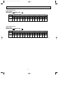
PERFORMANCE DATA
HEAT operation
MSZ-A09RV - E1 MUZ-A09RV - E1
CAPACITY : 3.6 kW INPUT : 990 W
OUTDOOR WB(:)
INDOOR
-10
-5
0
5
10
15
20
DB(:)
Q INPUT Q INPUT Q INPUT Q INPUT Q INPUT Q INPUT Q INPUT
15
2.27 644 2.74 772 3.20 871 3.67 941 4.14 1000 4.57 1030 5.04 1049
21
2.16 693 2.59 822 3.06 911 3.49 980 3.96 1030 4.39 1059 4.84 1099
26
1.94 743 2.41 871 2.84 960 3.31 1030 3.78 1079 4.21 1109 4.68 1139
PERFORMANCE DATA
HEAT operation
MSZ-A12RV - E1 MUZ-A12RV - E1
CAPACITY : 4.8 kW INPUT : 1580 W
OUTDOOR WB(:)
INDOOR
-10
-5
0
5
10
15
20
DB(:)
Q INPUT Q INPUT Q INPUT Q INPUT Q INPUT Q INPUT Q INPUT
15
3.02 1027 3.65 1232 4.27 1390 4.90 1501 5.52 1596 6.10 1643 6.72 1675
21
2.88 1106 3.46 1311 4.08 1454 4.66 1564 5.28 1643 5.86 1691 6.46 1754
26
2.59 1185 3.22 1390 3.79 1533 4.42 1643 5.04 1722 5.62 1770 6.24 1817
NOTE
Q :Total capacity (kW) INPUT:Total power input (W) DB : Dry-bulb temperature WB: Wet-bulb temperature
22
OB230-1.qxp
02.5.28 7:36 PM
9
Page 23
MICROPROCESSOR CONTROL
MSZ-A09RV- E1 MUZ-A09RV- E1
MSZ-A12RV- E1 MUZ-A12RV- E1
Once the controls are set, the same operation mode can be repeated by simply turning the OPERATE/STOP(ON/OFF) button
ON.
Indoor unit receives the signal with a beep tone.
When the system turns off, 3-minute time delay will operate to protect system from overload and compressor will not restart for
3 minutes.
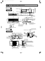
WIRELESS REMOTE CONTROLLER
Signal transmitting section
Operation display section
AM
PM
CLOCK
6 00 1 1 00
OPERATE /STOP
(ON /OFF)button
ON/OFF
TOO
WARM
TOO
COOL
OPERATION SELECT button
TEMPERATURE buttons
MODE I FEEL COOL DRY HEAT
FAN
VANE
ECONO COOL
SWING
START
STOP
VANE CONTROL button
FAN SPEED CONTROL button
ECONO COOL button
ON-TIMER button
CLOCK SET button
HR. button
MIN. button
(TIME SET button)
SWING button
OFF-TIMER button
HR. CLOCK MIN.
RESET button
RESET
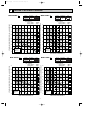
INDOOR UNIT DISPLAY SECTION
GREEN SIGN
GREEN SIGN shows the current room temperature and set temperature.
The room temperature indicated on the temperature monitor lamp may not be exactly the same as the actual room
temperature.
Available the set temperature range is 16:~31:, however, indication range of temperature monitor lamp is 21:~30:.
The set temperature (lighting) and room temperature (blinking) are displayed.
1.When the room temperature or set temperature is out of the indication range
If the set temperature is lower than 21:, indicating lamp at 21: is lighting. And if the room temperature is lower
than 21:, indicating lamp at 21: is blinking.
If the set temperature is higher than 30:, indicating lamp at 30: is lighting. And if the room temperature is higher
than 30:, indicating lamp at 30: is blinking.
(Example) When the set temperature is 28:, indicating lamp at 28:
is lighting.
When the room temperature is 30: or higher, indicating
lamp at 30: is blinking.
Lighting lamp shows Blinking lamp shows
the set temperature the room temperature
GREEN SIGN
21 22 23 24 25 26 27 28 29 30
2.When the room temperature or set temperature is within the indication range
(Example) When the set temperature is 26:, indicating lamp at 26:
is lighting.
When the room temperature is 27.5: or higher and lower
than 28.5:, indicating lamp at 28: is blinking.
Lighting lamp shows Blinking lamp shows
the set temperature the room temperature
GREEN SIGN
21 22 23 24 25 26 27 28 29 30
w When the set temperature and room temperature are the same, corresponding indicating lamp is lighting.
NOTE:
When the unit is not operating
: Both POWER MONITOR lamp and green sign lamps are off.
When ON- Timer is set
: POWER MONITOR lamp is on. All green sign lamps are off.
When OFF- Timer is set
: The lamp indication is as same as ordinary operation.
23
OB230-1.qxp
02.5.28 7:36 PM
Page 24
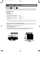
9-1. “I FEEL CONTROL” (
) OPERATION
1. Press OPERATE/STOP(ON/OFF) button on the remote controller. POWER MONITOR lamp of the indoor unit will turn
on with a beep tone.
2. Press OPERATION SELECT button to set “I FEEL CONTROL”(
) Then a beep tone is heard.
3. The operation mode is determined by the room temperature at start-up of the operation.
Initial room temperature
Mode
more than 25:
COOL mode of
"I FEEL CONTROL"
23: to 25:
DRY mode of
"I FEEL CONTROL"
less than 23:
HEAT mode of
"I FEEL CONTROL"
● Once the mode is fixed, the mode will not change by room temperature afterwards.
● Under the ON-TIMER (
) operation, mode is determined according to the room temperature as the operation
starts.
● When the system is stopped with the OPERATE/STOP(ON/OFF) button on the remote controller, and restarted within 2
hours in “I FEEL CONTROL” (
temperature.
) mode, the system operates in previous mode automatically regardless of the room
Example
Restart
COOL mode of “I FEEL
CONTROL”
Previous operation
COOL mode of
“I FEEL CONTROL”
When the system is restarted after 2 hours, the operation mode is determined by the initial room temperature at start-up
of the operation.
Example
Previous operation COOL mode of
“I FEEL CONTROL”
or COOL mode
Restart
COOL or DRY or HEAT
mode of “I FEEL CONTROL”
that determined by room
temperature start-up of the
operation.
4. The initial set temperature is decided by the initial room temperature.
Model
Initial room temperature
COOL mode of
"I FEEL CONTROL"
26: or more
Initial set temperature
24:
❈1
26: or less
Initial room temperatureminus 2:
DRY mode of
"I FEEL CONTROL"
23: to 25:
Initial room temperatureminus 2:
HEAT mode of
"I FEEL CONTROL"
23: or less
26:
❈1 When the system is restarted with the remote controller, the system operates with the previous set temperature regardless of the room temperature at restart.
The set temperature is calculated by the previous set temperature.
24
OB230-1.qxp
02.5.28 7:36 PM
Page 25
5. TEMPERATURE buttons
In “I FEEL CONTROL” (h)mode, set temperature is decided by the microprocessor based on the room temperature.
In addition, set temperature is controlled by TOO WARM or TOO COOL buttons when you feel too cool or too warm.
Pressing the TOO WARM or TOO COOL button emits a beep tone.
● Fuzzy control
When the TOO COOL or TOO WARM button is pressed, the microprocessor changes the set temperature, considering
the room temperature, the frequency of pressing TOO COOL or TOO WARM button and the user’s preference to heat or
cold. So this is called “Fuzzy control”, and works only in “I FEEL CONTROL” mode.
In DRY mode of “I FEEL CONTROL”, the set temperature doesn’t change.
▼ TOO
COOL … To raise the set temperature 1 ~ 2 degrees (: )
▲ TOO
WARM … To lower the set temperature 1 ~ 2 degrees (:)
9-1-1. Cool mode of “I FEEL CONTROL”
Difference between room
temperature and set temperature during operation.
1. Following are the fan speed in AUTO.
Fan speed
Temperature difference
Room temperature minus set temperature: 2 degrees or more ·································High
Room temperature minus set temperature: 1 degree or more and less than 2 degrees ··········Med.
2 deg. 4 deg.
Room temperature minus set temperature: less than 1 degree ·································Low
1.5 deg.
1
deg.
2. Time control
When the three conditions below have been satisfied for 1 hour and 45 minutes, compressor stops for 3 minutes.
(1).Compressor has been continuously operating.
(2).Indoor fan speed is Low or Med.
(3).Room temperature is below 26:.
When compressor turns off half way,.the accumulated time is cancelled.
When compressor turns on again, time counting starts from the beginning.
When the indoor fan speed becomes High or the room temperature exceeds 26:, time counting stops temporarily.
After, when the above conditions are satisfied again, time counting restarts.
The indoor fan operates at set speed.
3. Coil frost prevention mode
The operational frequency of the compressor is controlled based on the temperature of the indoor coil thermistor(RT12).
Temperature of indoor coil thermistor:Th
Operation frequency
approx. 8°C or above
normal
approx. 6°C to 8°C
fixed
approx. 3°C to 6°C
lower at the rate of 3Hz/min
approx. 3°C or below
lower at the rate of 6Hz/min
Compressor is turned OFF for 5 minutes when temperature of indoor
coil thermistor continues approx. 3°C or below for 5 minutes or more.
• The indoor fan maintains the actual speed of the moment.
9-1-2. DRY mode of “I FEEL CONTROL”
The system for dry operation uses the same refrigerant circuit as the cooling circuit.
The compressor and the indoor fan are controlled by the temperature.
By such controls, indoor flow amounts will be reduced in order to lower humidity without much room temperature
decrease.
The operation of the compressor and indoor fan is as follows.
Compressor operates by temperature control and time control.
1 Set temperature is controlled to fall 2°C as initial set temperature.
2 Indoor fan and outdoor fan operate in the same cycle as the compressor.
3 Operational frequency control of compressor is fixed 30Hz.
NOTE ● Coil frost prevention during DRY mode of “I FEEL CONTROL”
The operation is same as coil frost prevention during COOL mode of “I FEEL CONTROL” .
25
OB230-1.qxp
02.5.28 7:36 PM
Page 26
Defrosting in DRY mode
The operational frequency of the compressor is controlled based on the temperature of the indoor coil thermistor (RT12).
Temperature of indoor coil thermistor:RT12
Operation frequency
approx. 8°C or above
normal
approx. 6°C to 8°C
fixed
approx. 3°C to 6°C
lower at the rate of 3Hz/min
approx. 3°C or below
lower at the rate of 6Hz/min
Compressor is turned OFF for 5 minutes when temperature of indoor
coil thermistor continues approx. 3°C or below for 5 minutes or more.
The indoor fan maintains the actual speed of the moment. However, it changes to Low speed when the compressor stops.
9-1-3. HEAT mode of “I FEEL CONTROL”
1. Indoor fan speed control
(1) Indoor fan operates at the set speed by FAN SPEED CONTROL button.
In Auto the fan speed is as follows.
Fan speed
Initial temperature difference
Set temperature minus room temperature: 2 degrees or more················································· High
Set temperature minus room temperature: Between 1 and 2 degrees ····································· Med.
Set temperature minus room temperature: less than 1 degree················································· Low
Difference between room
temperature and set temperature during operation
2 deg. 4 deg.
1 deg. 1.7 deg.
(2) Cold air prevention control
1 When the compressor is not operating,
(1) if the temperature of indoor coil thermistor RT12 is 18°C or less, the fan stops.
(2) if the temperature of indoor coil thermistor RT12 is more than 18°C, the fan operates at Very Low.
2 When the compressor is operating,
(1) if the temperature of RT12 is 22°C or more, the fan operates at set speed.
(2) if the temperature of RT12 is less than 22°C and
(1) if the temperature of room temperature thermistor RT11 is 15°C or less, the fan stops.
(2) if the temperature of room temperature thermistor RT11 is more than 15°C, the fan operates at Very Low.
Released
Cold Air Prevention
RT12
Fan speed
Set speed
Very Low or stop
18: 22:
NOTE : At initial and after defrosting, when the RT12 is from 18: to 22:, Cold Air Prevention control works.
(3) Warm air control.
When the following any condition of 1(a. ~ d.) and the condition of 2 are satisfied at the same time, warm air control
works.
1 a.) when the operation mode has been changed to HEAT mode
b.) when cold air prevention has been released
c.) when defrosting has been finished
d.) when the compressor starts in HEAT mode
2 When the temperature of indoor coil thermistor RT12 is less than 37°C.
When warm air control works, the fan speed changes as follows to blow out warm air gradually.
Gradation of fan speed in initial
<Time condition>
<Indoor fan speed>
less than 2 minutes
2 minutes to 4 minutes
more than 4 minutes
Low
Med.
High
The upper limit of the fan speed in MANUAL is the set speed.
The upper limit of the fan speed in AUTO is the speed decided by indoor fan speed control.
When the temperature of RT12 has been 37°C or more, or when the set speed has been changed, this control is
released and the fan speed is the set speed.
(4) Flow soft control
When the thermostat (compressor) is off, the indoor fan operates as follows.
Compressor
OFF
ON
Fan
Very Low
Set speed
NOTE : When the thermostat(compressor) turns on, the fan will operate
at set speed. But until cold air prevention and warm air control
is released.
26
OB230-1.qxp
02.5.28 7:36 PM
Page 27
2. High pressure protection
In HEAT mode and manually-operated HEAT mode, the indoor coil thermistor detects the temperature at the indoor heat
exchanger and controls the compressor rotational frequency to prevent the condensing pressure from increasing excessively.
3. Overload starting
When the room temperature thermistor reads 18°C or above, the compressor runs with its maximum frequency regulated for
3 minutes after the start-up.
4. Defrosting in HEAT mode
(1) Starting conditions of defrosting
a) The defrost thermistor attached to the outdoor heat exchanger read -3°C or below.
b) The cumulative operation time of the compressor has reached any of the set values: 30, 40, 45, 55, 65, 75, 85, 95, 105,
115 minutes.
c) More than 5 minutes have passed since the start-up of the compressor.
When the above three conditions, a), b), and c), are satisfied, the defrosting starts.
wSet value of compressor operation time(hereinafter referred to as defrost interval)
The first defrost interval is 40 minutes long, and the second 45 minutes long.The third and subsequent intervals are set to
be longer, and less frequent, depending on defrosting time.
The third and subsequent defrost intervals follow any of the three patterns …5 or 10 minutes longer, the same, or 5 or 10
minutes shorter compared with the previous defrost interval … with the longest 115 minutes and the shortest 30 minutes.
(2) Releasing conditions of defrosting
Defrosting is released when any of the following condition is satisfied:
a) The defrost thermistor reads 13°C or above.
b) Defrosting time has exceeded 10 minutes.
c) Some other mode than HEAT mode is set during defrosting.
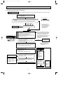
Time chart of defrosting in HEAT mode (reverse type)
Horizontal
Vertical vanes
Normal
Indoor fan
Normal
Very Low (temperature of indoor coil thermistor > 18:)
STOP
Normal
30
seconds
<outdoor unit>
MAX Hz
MAX Hz
100Hz
Compressor normal
1
30
second seconds
30
seconds
5 seconds
1
1
second second
5
seconds
Outdoor fan moter
Normal
Normal
OFF
4-way valve
ON
ON
OFF
27
OB230-1.qxp
02.5.28 7:36 PM
9-2. COOL (
Page 28
) OPERATION
(1) Press OPERATE/STOP(ON/OFF) button.POWER MONITOR lamp of the indoor unit turns on with a beep tone.
(2) Select COOL mode with the OPERATION SELECT button.
(3) Press TEMPERATURE buttons (TOO WARM or TOO COOL button)to select the desired temperature.
The setting range is 16 ~ 31°C
✻ Indoor fan continues to operate regardless of thermostat’s OFF-ON.
✻ Coil frost prevention is same as COOL mode of “I FEEL CONTROL”.
) OPERATION
(1) Press OPERATE/STOP(ON/OFF) button.
POWER MONITOR lamp of the indoor unit turns on with a beep
tone.
(2) Select DRY mode with the OPERATION SELECT button.
(3) The microprocessor reads the room temperature and determines
the set temperature. Set temperature is as shown on the right
chart.
(4) DRY operation will not work when the room temperature is
13°C or below.
30
Set temperature
9-3. DRY (
Set temperature and
: initial room temperature in dry mode
35
25
20
15
10
) OPERATION
10
15
20
25
30
(1) Press OPERATE/STOP(ON/OFF) button.
Initial room temperature
POWER MONITOR lamp of the indoor unit turns on with a beep
tone.
(2) Select HEAT mode with the OPERATION SELECT button.
(3) Press TEMPERATURE buttons (TOO WARM or TOO COOL button) to select the desired temperature.
The setting range is 16 ~ 31°C.
9-4. HEAT (
35 :
9-5. FAN MOTOR CONTROL
1. Rotational frequency feedback control
The indoor fan motor is equipped with a rotational frequency sensor, and outputs signal to the microprocessor to feedback the rotational frequency. Comparing the current rotational frequency with the target rotational frequency
(High,Med.,Low) the microprocessor controls SR141 and adjusts fan motor electric current to make the current rotational
frequency close to the target rotational frequency. With this control, when the fan speed is switched, the rotational frequency changes smoothly.
High
High
Med.
Low
2. Fan motor lock-up protection
When the rotational frequency feedback signal is not output for 12 seconds, (or when the microprocessor cannot detect
the signal for 12 seconds) the fan motor is regarded locked-up. Then the electric current to the fan motor is shut off. 3
minutes later, the electric current is applied to the fan motor again. During the fan motor lock-up, the POWER MONITOR
lamp flashes to show the fan motor abnormality. (See page 42.)
28
OB230-1.qxp
02.5.28 7:36 PM
Page 29
9-6. AUTO VANE OPERATION
1. Vane motor drive
These models are equipped with a stepping motor for the horizontal vane. The rotating direction, speed, and angle of the
motor are controlled by pulse signals (approx. 12V) transmitted from indoor microprocessor.
2. The horizontal vane angle and mode changes as follows by pressing the VANE CONTROL button.
3. Positioning
The vane is once pressed to the vane stopper below to confirm the standard position and then set to the desired angle.
The positioning is decided as follows.
(a) When the OPERATE / STOP(ON / OFF) button is pressed.(POWER ON/OFF)
(b) When the vane control is changed AUTO to MANUAL.
(c) When the SWING is finished.
(d) When the test run starts.
(e) When the power supply turns ON.
4. VANE AUTO (
) mode
In VANE AUTO mode, the microprocessor automatically determines the vane angle and operation to make the optimum
room-temperature distribution.
(1) In COOL and DRY operation
Vane angle is fixed to Angle 1.
Vane angle is fixed to Angle 4.
(2) In HEAT operation
5. Dew prevention
During COOL or DRY operation with the vane angle at Angle 4 or 5 when the compressor cumulative operation time
exceeds 1 hour, the vane angle automatically changes to Angle 1 for dew prevention.
6 SWING MODE (
)
By pressing the SWING button, vane swings horizontally. The remote controller displays “ ”.
SWING MODE is cancelled when any of the following operations are performed.
● The unit is turned off.
The vertical vanes will return to their positions just before the swing operation was started.
● The operation mode(AUTO, COOL, DRY or HEAT)is changed.
The vertical vanes will return to their positions just before the swing operation was started.
● The SWING button is pressed.
The vertical vanes stop at the position when the button is pressed.
29
OB230-1.qxp
02.5.30 11:20 AM
Page 30
7 Horizontal AIR FLOW ( )
The vertical vane angle changes as follows by pressing the SWING button.
● Press the SWING button.
The vertical vanes begin moving.
● When the vertical vanes move to the desired position, press the SWING button again.
The vertical vanes stop moving.
NOTE
If the SWING button is not pressed again within 30 seconds in COOL or DRY mode or within 1 minute in HEAT mode
after the vertical vanes start moving, the vertical vanes will automatically return to their original positions.
Horizontal AIR FLOW blowing range
About 100COOL and DRY
About 150HEAT
8. Cold air prevention in HEAT operation.
When any of the following conditions occurs in HEAT operation,
the vane angle changes to Angle 1 automatically to prevent cold Indoor coil thermistor RT12 temperature
air blowing on users.
① Compressor is not operating.
Horizontal vane
➁ Defrosting is performed.
Released
Set position
➂ Indoor coil thermistor RT12 reads 24: or below.
Cold Air Prevention
Angle 1
➃ Indoor coil thermistor RT12 temperature is raising from 24°C or
24:
28:
below, but it does not exceed 28:.
NOTE: If the temperature of RT12 reads from 24: to 28: at the air conditioner starting, this control works.
9. ECONO COOL (
) operation (ECONOmical operation)
When the ECONO COOL button is pressed in COOL mode, set temperature is automatically set 2°C higher than that in
COOL mode.
Also the horizontal vane swings in various cycle according to the temperature of indoor heat exchanger(RT12).
SWING operation makes you feel cooler than set temperature. So, even though the set temperature is higher than that in
COOL mode, the air conditioner can keep comfort. As a result, energy can be saved.
ECONO COOL operation is cancelled when the ECONO COOL button is pressed once again or VANE CONTROL button is
pressed or change to other operation mode.
NOTE : ECONO COOL operation not work in COOL mode of “I FEEL CONTROL”.
SWING operation
In swing operation of ECONO COOL mode, the initial air flow direction is adjusted to “Horizontal”.
According to the temperature of indoor coil thermistor RT12 at starting of this operation, next downward blow time is
decided. Then when the downward blow has been finished, next horizontal blow time is decided.
For initial 10 minutes the swing operation is performed in table G~H for quick cooling.
Also, after 10 minutes when the difference of set temperature and room temperature is more than 2:, the swing operation
is performed in table D~H for more cooling.
The air conditioner repeats the swing operation in various cycle as follows.
Temperature of indoor
coil thermistor RT12
Downward blow time
(sec.)
Horizontal blow time
(sec.)
15°C or less
2
23
15°C to 17°C
5
20
D
17°C to 18°C
18°C to 20°C
8
11
17
14
E
20°C to 21°C
14
11
F
G
21°C to 22°C
17
8
22°C to 24°C
5
H
more than 24°C
20
23
A
B
C
30
2
OB230-2.qxp
02.5.28 7:37 PM
Page 31
9-7. TIMER OPERATION
1. How to set the timer
(1) Press OPERATE/STOP(ON/OFF) button to start the air conditioner.
(2) Check that the current time is set correctly.
NOTE : Timer operation will not work without setting the current time. Initially “AM0:00” blinks at the current time display
of TIME MONITOR, so set the current time correctly with CLOCK SET button.
(3) Press ON or OFF TIMER buttons to select the operation.
“
” button... AUTO START operation (ON timer)
“
” button... AUTO STOP operation (OFF timer)
(4) Press HR. and MIN. button to set the timer. Time setting is 10-minute units.
HR. and MIN. button will work when “
” or “
” mark is flashing.
These marks disappear in 1 minute.
After setting the ON timer, check that POWER MONITOR lamp of the indoor unit lights.
NOTE1 : Be sure to place the remote controller at the position where its signal can reach the air conditioner even during
TIMER operation, or the set time may deviate within the range of about 10 minutes.
NOTE2 : Reset the timer in the following cases, or the set time may deviate and other malfunctions may occur.
● A power failure occurs.
● The circuit breaker functions.
2. Cancel
TIMER setting can be cancelled with the ON or OFF TIMER buttons. (“
To cancel the ON timer, press the “
” or “
”)
” button.
To cancel the OFF timer, press the “
” button.
TIMER is cancelled and the display of set time disappears.
PROGRAM TIMER
● The OFF timer and ON timer can be used in combination.
●“
” and “
” display shows the order of the OFF timer and ON timer operation.
(Example 2) The current time is 11:00 AM.
(Example 1) The current time is 8:00 PM.
The unit turns on at 5:00 PM, and off at 9:00 PM.
The unit turns off at 11:00 PM, and on at 6:00 AM.
NOTE : TIMER setting will be cancelled by power failure or breaker functioning.
31
OB230-2.qxp
02.5.28 7:37 PM
Page 32
9-8. EMERGENCY-TEST OPERATION
In case of test run operation or emergency operation, use the EMERGENCY OPERATION switch on the front of the
indoor unit. Emergency operation is available when the remote controller is missing, has failed or the batteries of remote
controller run down. The unit will start and the POWER MONITOR lamp will light.
The first 30 minutes of operation is the test run operation. This operation is for servicing. The indoor fan speed runs at
High speed and the system is in continuous operation. (The thermostat is ON.)
After 30 minutes of test run operation the system shifts to EMERGENCY COOL/HEAT MODE with a set temperature of
24°C.
The fan speed shifts to Med. speed.
The coil frost prevention works even in emergency operation, and defrosting too.
In the test run or emergency operation, the horizontal vane operates in VANE AUTO mode.
Emergency operation continues until the EMERGENCY OPERATION switch is pressed once or twice or the unit receives
any signal from the remote controller. In case of latter normal operation will start.
NOTE : Do not press the EMERGENCY OPERATION switch during normal operation.
Lighting lamp shows
the set temperature
Blinking lamp shows
the room temperature
GREEN SIGN
Press once
< Cooling >
EMERGENCY
OPERATION switch
Press again
< Heating >
Press once again
< Stop >
Light up
9-9. POWER MONITOR LAMP
Color of the lamp
RED
ORANGE
GREEN
Operating condition
The unit operates at high power.
The unit operates at middle power.
The unit operates with energy-saving.
The color of POWER MONITOR lamp is GREEN in any of the following cases.
• When ON-timer is standby
• In DRY operation
• In EMERGENCY operation
• When defrosting of the outdoor unit is being done in HEAT operation
32
21 22 23 24 25 26 27 28 29 30
GREEN SIGN
21 22 23 24 25 26 27 28 29 30
GREEN SIGN
21 22 23 24 25 26 27 28 29 30
Blinking light
OB230-2.qxp
02.5.28 7:37 PM
Page 33
9-10. Operational frequency control of outdoor unit
1. Outline
The operational frequency is decided by following the procedures below:
First, set the target operational frequency based on the difference between the room temperature and the set temperature.
Second, regulate the target operational frequency by discharge temperature protection, high pressure protection, electric
current protection and overload protection and also by the maximum/minimum frequency.
(1) maximum/ minimum frequency in each operation mode.
COOL (indoor fan speed : High)
Model
HEAT
Minimum
Rating
Maximum
Minimum
Rating
Maximum
DRY
frequency
frequency
frequency
frequency
frequency
frequency
MSZ-A09RV
15
53
80
16
67
98
22/27
MSZ-A12RV
15
82
88
16
98
115
22/27
w The maximum frequency in COOL mode is limited according to operation hours, as shown below.
Maximum
frequency
frequency
Rating or under-rating frequency
1Hr
Time
(2) Frequency change speed
During increasing frequency
Operational frequency
MUZ-A09RV-
E1
MUZ-A12RV-
10Hz to 14Hz
0.5 sec./Hz
15Hz to 79Hz
5 sec./Hz
80Hz to 150Hz
0.5 sec./Hz
E1
During decreasing frequency
Operational frequency
MUZ-A09RV-
E1
MUZ-A12RV-
10Hz to 42Hz
1 sec./Hz
43Hz to 150Hz
0.5 sec./Hz
33
E1
OB230-2.qxp
02.5.28 7:37 PM
Page 34
9-11 .Electronic expansion valve control (LEV control)
(1)Outline of LEV control
The LEV basic control is comprised of setting LEV opening degree to the standard opening degrees set for each operational frequency of the compressor. However, when any change in indoor/outdoor temperatures or other factors cause air
conditioning load fluctuation, the LEV control also works to correct LEV opening degree based on discharge temperature
(Shell temperature) of the compressor, developing the unit’s performance.
general operation
standard
specification
(2)Specification of LEV control
Control range
from min. 33 pulse to max. 500 pulse.
Actuating speed
LEV opens 40 pulse/sec. and close 90 pulse/sec.
Opening degree adjustment
LEV opening degree is always adjusted in opening direction.
(When reducing the opening degree, LEV is once overclosed, and then adjusted to the proper degree by opening.
Unit OFF
LEV remains at max. opening degree (reaches max. opening
degree approx. 15 minutes after compressor stops)
Remote controller ON
LEV is positioned. (first full-closed at zero pulse and then
positioned.)
During 2 to 15 minutes after compressor starts
Opening degree is adjusted according to standard opening
degree.
(Standard opening degree is set for each rotational frequency of compressor)
More than 15 minutes have passed since compressor
start-up
LEV opening degree is corrected to get target discharge
temperature of compressor.
(For discharge temperature lower than target temperature,
LEV is corrected in closing direction.)
(For discharge temperature higher than target temperature,
LEV is corrected in opening direction.)
wIt may take more than 30 minutes to reach target temperature, depending on operating conditions.
Thermostat OFF
LEV starts to open every 3 pulse/sec.
from
the same opening degree as that when the Unit turned IFF
(and becomes full-opened after approx. 15 minutes.)
Thermostat ON
LEV is controlled in the same way as that is after the compressor has started up.
Defrosting in HEAT mode
LEV is adjusted to open 350 pulse.
34
02.5.28 7:37 PM
Page 35
(3) Time chart
Air conditioner ON
Air conditioner OFF
(thirmostat off)
LEV opening degree
Positioning
Standard
opening
degree
Opening degree is
corrected according
to discharge
temperature
Commanded
to open
Time
15 min.
The operational frequency of the compressor
ON
OFF Time
(4) Control data
(a) Reference value of target discharge temperature
(Cooling :/Heating :)
A
B
C
D
E
F
58/49
60/58
68/67
70/70
72/72
72/72
LEV opening degree
OB230-2.qxp
06
05
04
03
02
01
F
E
D
C
B
A(target discharge temperature)
30
50
70
90
110
130 (Hz)
The operational frequency of the compressor
In COOL mode, the two indoor coil thermistor (one main and one sub) sense temperature ununiformity (super heat) at the
heat exchanger, and when temperature difference have developed, the indoor coil thermistors adjust LEV opening to get
approximate 10 degrees lower temperature than the target temperature in the table above, thus diminishing super heat.
(b) Reference value of LEV standard degree opening
(COOL/HEAT pulse)
01
02
03
04
05
06
110/80 150/100 200/120 200/130 200/130 200/130
35
OB230-2.qxp
02.5.28 7:37 PM
Page 36
9-12.Outdoor fan motor control
The AC fan motor turns ON/OFF, interlocking with the compressor.
[ON]
The AC fan motor turns on 5 seconds before the compressor starts up.
[OFF]
The AC fan motor turns off 15 seconds after the compressor stops running.
5 sec.
ON
15 sec.
Compressor
OFF
ON
Outdoor fan
OFF
9-13. 4-way valve control
COOL&DRY mode . . . . . . . . . ON(voltage applied)
The 4-way valve turns ON as soon as thermostat turns ON.
The 4-way valve turns OFF 15 minutes after the thermostat turns OFF.
HEAT mode . . . . . . . . . . . . . . . OFF(voltage not applied)
During normal HEAT operation the 4-way valve is OFF.
w The 4-way valve does not turn ON before the compressor starts up.
Compressor
ON
OFF
4-way valve
ON
OFF
Outdoor fan
ON
OFF
<COOL>
<HEAT>
5 seconds
5 seconds
36
OB230-2.qxp
02.5.28 7:37 PM
Page 37
9-14. Indoor fan motor control
The detected rotational frequency of the fan motor is feed backed to the microprocessor and then the microprocessor works
to keep the rotational frequency at a fixed value against load fluctuation.
(1) Circuit block diagram
SSR output
every 100Hz pulse output
Microprocessor
AC motor
AC motor
actuator (SSR)
220~240V AC
Rotational frequency
Rotational
frequency
sensor
part
controller board
Output
Input
(2) Control system
<Output side>
The microprocessor outputs pulse
every 100Hz (every 50Hz in half wave).
(Fan speed varies according to the
time span between a Zero-cross point
on the commercial wave and a pulse
out put point.)
The microprocessor drives SSR on
relay P.C. board.
Controlled voltage
is applied to AC
fan motor.
<Input side>
The microprocessor detects rotational
frequency of AC fan motor, using Hall
element in AC fan motor.
The microprocessor adjusts rotational
frequency.
If feed backed pulses are not detected for 12
seconds, fan motor becomes abnormal and
indoor POWER MONITOR lamp flashes to
show abnormality.
37
OB230-2.qxp
02.5.28 7:37 PM
10
Page 38
SERVICE FUNCTIONS
MSZ-A09RV - E1 MUZ-A09RV - E1
MSZ-A12RV - E1 MUZ-A12RV - E1
10-1. CHANGE IN DEFROST SETTING
<JP7> When the JP7 wire of the outdoor electronic control P.C. board is cut, the defrost temperature will be changed.
(Refer to page 55.)
Jumper wire
Change point
Deforst finish temperature changes from 13: to 15:.
JP7
10-2. TIMER SHORT MODE
For service, set time can be shortened by short circuit of JPG and JPS the electronic control P.C. board.
The time will be shortened as follows. (Refer to page 54.)
Set time : 1 minute ➔ 1-second
Set time : 3 minute ➔ 3-second (It takes 3 minutes for the compressor to start operation. However, the starting time is
shortened by short circuit of JPG and JPS.)
10-3. P.C. BOARD MODIFICATION FOR INDIVIDUAL OPERATION
A maximum of 4 indoor units with wireless remote controllers can be used in a room. In this case, to operate each indoor
unit individually by each remote controller, P.C. boards of remote controller must be modified according to the indoor unit
number.
How to modify the remote controller P.C. board
Remove batteries before modification.
The board has a print as shown below;
NOTE : Fore re-modelling, take out the batteries at first.
After finish re-modelling, put back the batteries then push the RESET-button.
The P.C. board has the print “J1” and “J2”. Jumper wires are mounted to each “J1” and “J2”.Cut “J1” and “J2” according to
the number of indoor unit as shown in Table 1.
After modification, push the RESET. button near the MIN-button on the remote controller.
Table1.
No.1
No.2
No.3
No.4
unit
unit
unit
unit
1 unit operation
No modification
2 unit operation
Same as at left
Cut J1
3 unit operation
Same as at left
Same as at left
Cut J2
4 unit operation
Same as at left
Same as at left
Same as at left
Cut both J1 and J2
How to set the remote controller exclusively for particular indoor unit
After you turn the breaker ON, the first remote controller that sends the signal to the indoor unit will be regarded as the
remote controller for the indoor unit.
The indoor unit will only accepts the signal from the remote controller that has been assigned to the indoor unit once they
are set.
The setting will be cancelled if the breaker has turned off, or the power supply has shut down.
Please conduct the above setting once again after the power has restored.
38
OB230-2.qxp
02.5.30 11:19 AM
Page 39
10-4. AUTO RESTART FUNCTION
When the indoor unit is controlled with the remote controller, the operation mode, the set temperature, and the fan speed
are memorized by the indoor electronic control P.C.board. The “AUTO RESTART FUNCTION” sets to work the moment
the power has restored after power failure, then, the unit will restart automatically. If the unit is operated in “I FEEL CONTROL.” mode before power failure, the operation is not memorized. In “I FEEL CONTROL.” mode, the operation is decided by the initial room temperature at (re)start.
How to set “AUTO RESTART FUNCTION”
1Turn off the main power for the unit.
2Remove the indoor electronic control P.C. board and the display P.C.board.(See page 57.)
3Pull the indoor electronic control P.C. board forward and cut the RESISTOR JR07 on it.
C11
CN
21
1
CN201
CN121
SW
IC101
CN112
CN111
52C
CN151
JR07
Operation
1If the main power (220-240V AC) has been cut, the operation settings remain.
2After the power is restored, the unit restarts automatically according to the memory.(However, it takes at least 3 minutes
for the compressor to start running.)
NOTE:
•The operation settings are memorized when 10 seconds have passed after the indoor unit was operated with the remote
controller.
•If the main power is turned off or a power failure occurs while AUTO START/STOP timer is active, the timer setting is
cancelled.
•If the unit has been off with the remote controller before power failure, the auto restart function does not work as the
power button of the remote controller is off.
•To prevent breaker off due to the rush of starting current, systematize other home appliances not to turn on at the same
time.
•When some air conditioners are connected to the same supply system, if they are operated before power failure, the
starting current of all the compressors may flow simultaneously at restart.
Therefore, the special counter-measures are required to prevent the main voltage-drop or the rush of the starting current
by adding to the system that allows the units to start one by one.
39
OB230-2.qxp
11
02.5.28 7:37 PM
Page 40
TROUBLESHOOTING
MSZ-A09RV - E1 MUZ-A09RV - E1
MSZ-A12RV - E1 MUZ-A12RV - E1
11-1. Cautions on troubleshooting
1. Before troubleshooting, check the following:
1) Check the power supply voltage.
2) Check the indoor/outdoor connecting wire for mis-wiring.
2. Take care the following during servicing.
1) Before servicing the air conditioner, be sure to first turn off the remote controller to stop the unit, and then after confirming the horizontal vane is closed, turn off the breaker and / or disconnect the power plug.
2) Be sure to unplug the power cord before removing the front panel, the cabinet, the top panel, and the P.C. boards.
3) When removing the P.C. board, hold the edge of the board with care NOT to apply stress on the components.
4) When connecting or disconnecting the connectors, hold the housing of the connector, DO NOT pull the lead wires.
Housing point
Lead wiring
3. Caution for the outdoor unit repair service
1) Do not load on the P.C.board cover.
2) Since every P.C.board circuit links directly with
power supply 220~240V AC, do not short the
P.C.board and metal section on servicing. Also
if touch the parts on the P.C.board, it may cause
an electric shock.
3) When closing the P.C.board cover, prevent a
foreign matter or dust from coming inside the
P.C.board.
Cover
Electronic control P.C. board
Relay P.C. board
3. Troubleshooting procedure
1) First, check if the POWER MONITOR lamp on the indoor unit is flashing on and off to indicate an abnormality. To
make sure, check how many times the abnormality indication is flashing on and off before starting service work.
2) Before servicing check that the connector and terminal are connected properly.
3) If the P.C. board is supposed to be defective, check the copper foil pattern for disconnection and the components for
bursting and discoloration.
4) When troubleshooting, refer to the flow chart on page 41 and the check table on page 42 and 43.
4. How to replace batteries
Weak batteries may cause the remote controller malfunction.
In this case, the remote controller can not be repaired only by the battery replacement. To operate the remote controller
normally, replace the batteries in the following order.
This remote controller has the RESET button. After refilling new batteries, press the RESET button with tip end of ball
point pen or the like, and then use the remote controller.
2 Press the RESET button.
1 Remove the back lid and replace batteries.
Then re-attach the back lid.
Insert the negative pole
of the batteries first.
Check if the polarity of
the battereis is correct.
40
RESET button
OB230-2.qxp
02.5.28 7:37 PM
Page 41
11-2. Troubleshooting procedure
The following procedure facilitates identifying defective points.
The abnormalities in
can be located in the Troubleshooting check table on page 42~43.
Operation start
Indoor unit dose
not respond to
remote controller.
Indoor unit does not respond to
remote controller. In addition,
operation Power monitor lamp
dose not light up, with emergency operation switch ON.
Power monitor
lamp flashes.
3 time flash
2.5 seconds OFF
Indoor fan motor
dose not run.
Refer to G ‘Check of
indoor electronic control
P.C. board’ on page 49.
1-time flash
2.5 seconds
or
0.5 seconds
OFF
2 time flash
2.5 seconds OFF
Cause:indoor/outdoor
unit
· Mis-wiring
· Serial signal error
Refer to
‘Checking serial
signal error’ on
page 44.
Refer H ‘Check of indoor
electronic P.C. board’ on
page 50.
Cause: in Indoor unit
· Main indoor coil thermistor abnormality
· Room temperature
thermistor abnormality
· Sub indoor coil thermistor abnormality
Check :
indoor/outdoor
Mis-wiring on
page 44.
Refer to F ‘Check of
indoor fan motor’ on
page 49.
5-time flash
2.5 seconds OFF
6-time flash
2.5 seconds OFF
12-time flash
2.5seconds OFF
Check :
· Main indoor coil
thermistor
· Room temperature
thermistor
· Sub indoor coil
thermistor
7 time flash
2.5 seconds OFF
Cause: in outdoor unit
· Outdoor power system abnormality
· Outdoor unit temperature thermistor
abnormality
·Outdoor converter
power system abnormality.
Cause: in outdoor unit
· Outdoor control system
error
Refer to I
‘Check of outdoor thermistors’
on page 50.
Check :
Outdoor
electronic
control P.C.
board.
Inverter/Compressor
Refer to A ~ E
‘Compressor’ on
page 47 and 48.
Refer to A ~ E
‘Transistor module’
on page 47 and 48.
wIn case of serial signal
error, the mis-wiring
indication will appear
by turning the power
off and then turning it
back on.
Refer to L 'Check
of power supply' on
page 52.
Refer to J ‘Check
of R.V. coil’ on page
51.
Refer to K ‘Check
of outdoor fan
motor’ on page 51.
Refer to N ‘Check of electronic control P.C. board in
the outdoor unit’ on page 52.
Outdoor electronic
control P.C. board.
41
Refer to P ‘Check of
linear expansion valve
(LEV)’ on page 53.
OB230-2.qxp
02.5.28 7:37 PM
Page 42
1. Troubleshooting check table
MSZ-A09RV - E1
MSZ-A12RV - E1
(Indoor unit troubleshooting check table)
flash
· Flashing of the POWER MONITOR lamp indicates possible abnormalities.
· The POWER MONITOR lamp is lighting during normal operation.
No.
Symptom
Outdoor unit
does not
operate
Detection method
Checkpoint
repeated flashes
every 0.5 seconds
POWER MONITOR lamp
Mis-Wiring
Abnormal point
When indoor electronic control P.C. board does not
receive serial signals for 4 to 5 seconds with
OPERATION/STOP(ON/OFF) button of remote
controller ON and 52C relay ON for the first time,
NOTE: In case of serial signal error, mis-wiring
indication will appear by turning power off and
then turning it back on.
Refer to 'Checking
serial signal error' on
page 44.
1-time flash
2.5 seconds OFF
Serial signal
When indoor electronic control P.C. board does not
receive serial signals from outdoor unit for 4 to 5
seconds.
2-time flash
2.5 seconds OFF
Main indoor coil
thermistor
Sub indoor coil
thermistor
Room
temperature
thermistor
Indoor electronic control P.C. board constantly
detects resistance every 8 seconds.
When thermistor shorts or opens.
3-time flash
2.5 seconds OFF
Indoor fan motor
5-time flash
2.5 seconds OFF
6-time flash
2.5 seconds OFF
1
w2
w3
w4
5
When rotational frequency feedback signal is not
emit during 12-second indoor fan operation.
Refer to F "Check of
indoor fan motor" on
page 49.
Outdoor power
system
When compressor has stopped due to overcurrent
protection or start-up failure protection 3 times in a
row within 1 min. after start-up.
Refer to "How to
check
inverter/compressor"
on page 47.
Outdoor
thermistors
<Thermistor short>
Thermistors are abnormal when they short after
compressor start-up.
<Thermistor open>
Thermistors are abnormal when they open after
compressor start-up.
However, discharge temperature thermistor is
abnormal when open circuit is detected more than
10 min. after compressor start-up.
· Shortage of
refrigerant
· Outdoor electronic
control P.C. board
6
7
8
Refer to the
characteristics of main
indoor coil thermistor,
sub indoor coil
thermistor and room
temperature on page
54.
Refer to I "Check
of outdoor
thermistors" on
page 50.
7-time flash
2.5 seconds OFF
Outdoor control
system
When nonvolatile memory data cannot be read properly
on outdoor electronic control P.C. board, outdoor unit
stops and restarts 3 minutes later,
Replace outdoor
electronic control P.C.
board.
12-time flash
2.5 seconds OFF
Converter power
system
When the converter protective suspension within 1
minute after start-up of the converter is operated 5
times successively.
Also bus-bar voltage malfunction (140V or less or 400V
or more) within 1 minute after start-up of the converter
has happened 5 times successively.
Refer to N "Check of
outdoor electronic
control P.C.board" on
page 52.
wWhen the indoor unit has started operation and the above detection method has detected an abnormality (the first detection
after the power ON), the electronic control P.C. board turns OFF the 52C and the indoor fan motor with the operation indicator lamp lighting.
When the 52C and the indoor fan motor are turned ON again 3 minutes later and the same abnormality is detected (a second detection of the above abnormality after the power ON), the control P.C. board turns OFF the 52C and the indoor fan
motor with the operation indicator lamp flashing.
However, the first detection is cleared in case the power is turned OFF after the first detection.
42
OB230-2.qxp
02.5.28 7:37 PM
Page 43
(Outdoor LED indication table)
MUZ-A09RV - E1
MUZ-A12RV - E1
NOTE 1. The location of LED is illustrated at the right figure.
2. LED lights up during normal operation.
No.
1
Symptom
Outdoor unit
does not
operate
LED indication
2
NOTE:
For abnormality
location, refer to
'Indoor
troubleshooting
check table' on
page 43.
3
4
5
6
Abnormal point
Converter power
1-time flash every system
2.5 seconds
2-time flash
'Outdoor unit 2.5 seconds OFF
stops and
3-time flash
restarts 3
min. later' is 2.5 seconds OFF
repeated
Detection method
8
Outdoor unit
operates (at
low
frequency)
12
PFC
Flashing
LED
Checkpoint
Outdoor power
system
When compressor has stopped by overcurrent protection or
start-up failure protection within 1 min. after compressor startup 3 times in a row, compressor stops and then restarts 3 min.
later.
· Refer to 'Checking inverter/
compressor on page 47.
Outdoor
thermistors
When discharge temperature thermistor or fin temperature
thermistor shorts or opens during compressor running,
compressor stops and restarts 3 min. later.
· Refer to I 'Check of outdoor
thermistors' on page 50.
Outdoor control
system
When nonvolatile memory date cannot be read properly,
compressor stops and restarts 3 min. later.
Replace outdoor electronic control
P.C. board.
Over current
protection
When 19A current flows into power transistor, compressor
stops and restarts 3 min. later,
Refer to A-E in 'How to check
inverter/ compressor' on page 47~ 48.
Discharge
temperature
overheat
protection
When discharge temperature thermistor exceeds 116:,
compressor stops and restarts 3 min. later.
(Compressor restarts when discharge temperature thermistor
reads 100: or below.)
· Check refrigerant circuit and
refrigerant amount.
· Refer to I'Check of outdoor
thermistor' on page 50.
High pressure
5-time flash
2.5 seconds OFF protection
When indoor coil thermistor exceeds 75:, compressor stops
and restarts 3 min. later.
7-time flash
Mis-start up
2.5 seconds OFF protection
When switching from forced drive to normal drive
(synchronised operation by a position detectable signal) failed
5 times successively at compressor start-up.
Restart-up after suspension when miss start-up or abnormal
position detecting within 10 seconds after start-up.
8-time flash
Position detection
2.5 seconds OFF protection
When the position detectable signal is not input during normal
starting up (synchronised operation by a position detectable
signal) after 10 seconds of compressor operation.
9
10
IPM
When the converter protective suspension within 1 minute after
· Refer to N 'Check of electronic
start-up of the converter is operated 5 times successively.
control P.C. board on page 52.
Also bus-bat voltage malfunction (140V or less or 400V or
more) within 1 minute after- start-up of the converter has
happened 5 times successively.
Fin temperature
When temperature at heat sink exceeds 88: or outdoor
4-time flash
2.5 seconds OFF thermistor overheat electronic control P.C. board exceeds 67:, compressor stops
protection
and restarts 3 min. later.
7
11
<Outdoor electronic control P.C. board>
Frequency drop by When current from power outlet exceeds 10. A, compressor
1-time flash
2.5 seconds OFF current protection frequency lowers.
Frequency drop by When indoor coil thermistor exceeds 55: in HEAT mode,
3-time flash
compressor frequency lowers.
2.5 seconds OFF high pressure
protection
· Check around outdoor unit.
· Check outdoor unit air passage.
· Check refrigerant circuit and
refrigerant amount.
· Check stop valve.
Check and replace as follows.
1 Check the compressor connecting lead
wire between connector and transistor
module.
2 Check outdoor electronic control
P.C. board. (Position detecting circuit
IPM, Micro computer, etc)
3 Compressor replacement
Refer to A~E Inverter Compressor
simple check method on page 47 and 48.
The unit is normal, but check the
following.
· Check if indoor filters are clogged
· Check if refrigerant is short.
· Check if indoor/outdoor unit air
outlets are short cycled.
Frequency drop by When indoor coil thermistor reads 8: or below in COOL mode,
defrosting in COOL compressor frequency lowers.
mode
13
14
15
Outdoor unit
operates
4-time flash
Frequency drop by, When discharge temperature thermistor exceeds 111:,
2.5 seconds OFF discharge
compressor frequency lowers.
temperature
protection
Refer to I 'Check of outdoor
thermistors' on page 50.
5-time flash
Outdoor
2.5 seconds OFF thermistors
Defrost thermistor
Refer to I 'Check of outdoor
thermistors' on page 50.
low discharge
7-time flash
2.5 seconds OFF temperature
protection
When discharge temperature has been 50: or below for 20
min.
· Refer to P 'Check of LEV' on
page 53.
· Check refrigerant circuit and
refrigerant amount.
Converter
8-time flash
2.5 seconds OFF protection
When the converter suspends for protection
•Response abnormal suspension
•Bus-bar voltage abnormal suspension
•Converter overcurrent/ over voltage protective suspension
•Converter current detection abnormal suspension
•Converter zero cross abnormal suspension
· Refer to N 'Check of electronic
control P.C. board on page 52.
9-time flash
Inverter check
2.5 seconds OFF mode
When disconnecting the compressor connector, going to
inverter check mode.
· Refer to A~E Inverter Compressor
simple check method on page 47
and 48.
16
17
When defrost thermistor short or open.
w In this case, compressor continues running.
43
OB230-2.qxp
02.5.28 7:37 PM
Page 44
2. Checking mis-wiring and serial signal error.
Outdoor unit does not operate. When the POWER MONITOR lamp (on the left-hand side) flashes on and off continuously
or only once.
1. Turn OFF power supply.
2. Turn ON power supply.
3. Press the EMERGENCY OPERATION switch.
ON 2.5 seconds OFF ON
Is the self-check function of indoor unit indicated when relay 52C turns ON
3min. later?
wShort circuit of JPS (one-hour short circuit jumber cable) and JPG (GND
resistance) enables self-check function to be indicated within 3 min.
Serial signal error indication
Mis-wiring indication
Correct wiring
Yes
w1 If there is any error in
serial signal system, the
mis-wiring indication will
appear by turning the
power off and then
turning it back
Is there indoor-outdoor mis-wiring,
poor contact, or disconnection?
No
A
Turn off power supply and confirm that indoor-outdoor
wiring is correct.
Short-circuit indoor terminal block N and 3.
B While pressing OPERATE-STOP(ON/OFF) button on
remote controller, press RESET button.
(The above procedure allows Power monitor lamp to
indicate the failure-mode) w2
Does Power monitor lamp (on the right-hand
side) flash on and off when
OPERATE/STOP(ON/OFF) button on remote
controller is pressed?
Green Sign
21 22 23 24 25 26 27 28 29 30
flash
w2 Mis-wiring may damage the electronic
control P.C. board during the operation in
the left. Be sure to confirm the wiring is
correct before the operation starts.
w The serial signal indication on the Power
monitor lamp (right side) facilitates
checking abnormality, based on the
failure-mode
No
(light up or OFF)
w3 Replace indoor
electronic control
P.C. board.
Yes
Open-circuit indoor terminal block N and 3,
Check if there is amplitude of 5 to 10VDC between outdoor
terminal block N and 3 (for confirmation of serial signal)
and if there is 220-240V AC between 2 and N.
1. Unplug the power cord.
2. Disconnect the connector between compressor and IPM.
3. Plug the power cord.
4. Press EMERGENCY OPERATION switch.
Yes
Replace in-out connecting
wire.
No
· Main circuit
· Reactor
No
· Noise filter P.C.
board
defective
· Connection of
connector
Is there approx. 220-240V AC between outdoor
terminal block 2 and 1 ?
Yes
Is there 370V DC between both ends of
smoothing capacitor(C62) on the electronic
control P.C. board?
Yes
Replace outdoor electronic control P.C. board.
44
w3 Be sure to release the
failure-mode recall function
after checking.
A
· Turn off invertercontrolled
lighting
equipment.
· Plug the power
cord.
· Press
EMERGENCY
OPERATION
switch.
Is mis-wiring or
· Keep the unit
serial signal error
away from
No fluorescent
indicated when
relay 52C turns
light.
ON 3 min. later?
· Attach a filter
to lightintercepting
Yes
part.
B
OB230-2.qxp
02.5.28 7:37 PM
Page 45
3. Trouble shooting procedure of main parts
(Simple check method of main parts)
MSZ-A09RV - E1 MUZ-A09RV - E1
MSZ-A12RV - E1 MUZ-A12RV - E1
Part name
Checking method and criterion
Room temperature
thermistor(RT11)
Indoor coil thermistor
(RT12,RT13)
Disconnect the connector and measure the resistance with a tester.
(Part temperature : 10:~30:)
Normal
Abnormal
8k"~20K"
Open or short circuit
Disconnect the connector and measure the resistance with a tester.
(Part temperature : -10:~40:)
Defrost
thermistor
(RT62)
Normal
Abnormal
5k"~55K"
Open or short circuit
Disconnect the connector and measure the resistance with a tester.
Before measurement, hold the thermistor with your hands to warm it up.
(Part temperature : 20:~40:)
Discharge
temperature
thermistor
(RT61)
Normal
Abnormal
100k"~250K"
Open or short circuit
Disconnect the connector and measure the resistance with a tester.
(Part temperature : -10:~80:)
Fin temperature
thermistor
(RT64)
2
Abnormal
5k"~30K"
Open or short circuit
Disconnect the connector and measure the resistance between the terminals with a tester.
(Winding temperature : -10:~40:)
Compressor
(MC)
WHT
Normal
RED BLK
3
1
W
V
Normal
Abnormal
0.82"~1.01"
Open or short circuit
U
Compressor motor
Measure the resistance between the terminals with a tester.
(Winding temperature : 10:~30:)
Indoor fan
motor(MF)
WHT
RED
BLK
Terminal
1
2
3
Normal
(CN211)
WHT-BLK
280"~304"
BLK-RED
311"~338"
45
Abnormal
Open or short circuit
OB230-2.qxp
02.5.28 7:37 PM
Part name
Checking method and criterion
Measure the resistance between the terminals with a tester.
(Winding temperature : -10:~40:)
Outdoor fan
motor(MF61)
YLW
RED
ORN
WHT
P
BLK
Page 46
Terminal
Normal
WHT-BLK
173.7'~212.6'
BLK-RED
277.8'~339.9'
YLW-BLK
11.4'~14.1'
Open or short circuit
Measure the resistance between the RED terminal and the other ones.
(Winding temperature : 20:~30:)
Horizontal vane
motor(MV1)
Vertical vane
motor(MV2)
Normal
PNK
Abnormal
Abnormal
ROTOR
approx. 300' in each
phase
ORN
RED
YLW
Open or short circuit.
BLU
Measure the resistance between the terminals with a tester.
(Part temperature : -10:~40:)
R.V. coil
(21S4)
Normal
Abnormal
Open or short circuit.
882'~1079'
Measure the resistance with a tester.
(Part temperature : -10:~40:)
Linear expansion valve
(LEV)
Normal
Abnormal
42'~52'
Open or short circuit
(CN724)
LEV
WHT-RED
BLU3
RED-ORN
YLW5
BRN2
WHT6
RED1
ORG4
Terminal
YLW-BRN
BRN-BLU
46
OB230-2.qxp
02.5.28 7:37 PM
Page 47
(How to check inverter/compressor)
Start
Disconnect the connector between compressor and IPM.
Check voltage
between terminals.
Are voltages
balanced?
See A 'Check of open phase.'
No
Check resistance of IPM.
Yes
Yes
Check
compressor.
See B 'Check of IPM.'
Is resistance
infinite?
Outdoor electronic control
P.C. board is defective.
See C 'Check of compressor.'
No
(0~several ")
Replace outdoor electronic control P.C. board
and IPM.
IPM is defective.
A
Check of open phase
●Be sure to use the analog voltmeter for measurement
●Disconnect the connector between compressor and IPM , activate
the inverter and measure the balance of voltage between
terminals.
Output voltage : 120V
<Outdoor electronic control P.C. board>
IPM
<< Operation method>>
Start heating opration by pressing the Emergency operation switch
on the indoor unit. (test-run mode)
<<Measurement point>>
at 3 points
BLK-WHT
BLK-RED
WHT-RED
NOTE
B
Measure AC voltage, at 3 points more than one minute ofter
the outdoor fan motor starts running.
LED
PFC
flash
9 flashes
2.5 seconds OFF
Note 1. Output voltage changes depending power supply
voltage. (Max. i10%)
2. Measure by analogue tester.
3. During the measurement, LED in the outdoor electronic
control P.C. board flashes 9 times.
Check of IPM
●Disconnect the connector between compressor and IPM, and
measure resistance between terminals on the IPM.
<<Measurement point>>
at 6 points
BLK-WHT, WHT-BLK
BLK-RED, RED-BLK
w Measure resistance between
WHT-RED, RED-WHT
at 6 points the lead wires at 3 points
<<Judgment>>
Infinite ["]···········normal
0~dozens of ······abnormal (short)
ohmmeter indication
"
X1
Normal
(infinite)
"
X1
47
Abnormal
(0~dozens of ")
OB230-2.qxp
02.5.28 7:37 PM
C
Page 48
Check of compressor
See D 'Check of compressor winding'.
Check resistance of compressor.
Is resistance
1~several " at -10:
~ 40: of winding
temperature?
No
Compressor is short or
open.
Replace compressor.
Yes
Check compressor operation time.
Does compressor run
continuously?
See E ' Check of compressor operation time,'
No
Compressor is layer short
or lock-out.
Refrigerant circuit is
defective.
Replace compressor.
Check refrigerant circuit.
Yes
Ok
D
Check of compressor winding
● Disconnect the connector between compressor and IPM, and
measure resistance between the compressor terminals.
<<Measurement point>>
at 3 points
BLK-WHT
BLK-RED
w Measure resistace between the
WHT-RED
lead wires at 3 points.
<<Judgment>>
0.82 to 1.01" at -10: to 40: of part temperature.
0["] ···············abnormal [short]
Infinite["] ·······abnormal [open]
NOTE 1.Be sure to zero the ohmmeter before measurement.
2.Winding resistance for each phase is 0.45" at 20:.
WHT
Ohmmeter indication
2
RED BLK
3
1
W
"
X1
Normal
(1~several " )
V
U
Compressor motor
"
X1
Abnormal
(0" ····· short)
X1
Abnormal
(infinite····· open)
"
E
Check of compressor operation time
●Connect the compressor and activate the inverter. Then measure
the time until the inverter stops due to overcurrent.
<<Operation method>>
Start heating or cooling operation by pressing the emergency
operation switch on the indoor unit. (Test-run mode)
<<Measurement>>
Measure the time from the start of outdoor fan running till the
stop of the inverter due to overcurrent.
<<Judgment>>
For reference
0~10 seconds·····················abnormal (short)
10~60 seconds···················abnormal (compressor lock-out)
60 seconds~5 minutes·······abnormal (refrigerant circuit defect)
more than 5 minutes···········normal
48
0 sec.
10 sec.
Outdoor fan starts
Abnormal
(Compressor short circuit or layer short)
Abnormal
(Compressor lock-out)
60 sec.
Abnormal
(refrigerant circuit defect, etc.)
5 min.
Normal
OB230-2.qxp
02.5.28 7:37 PM
Page 49
(How to check main parts)
F
Check of indoor fan motor
Indoor fan does not operate.
Replace indoor
fan motor.
Are lead wires
disconnected?
Turn off power
supply and check
connector CN
211 visually.
Re-connect
lead wires.
Yes
No
Is soldered
point
abnormal?
No
Disconnect lead wires from
CN 211 on indoor electronic
control P.C. board.
Measure resistance
between lead wire 1 and 3
and then 2 and 3.
Yes
Is resistance
0" (short) or "
(open) ?
No
Yes
Re-solder it.
Replace indoor
electronic
control P.C.
board.
CN211
Indoor electronic
control P.C. board
3
2
1
fan
motor
G
Check of remote controller and indoor electronic control P.C. board.
Indoor unit operates by pressing the emergency operation switch.
Check the model
name of remote
controller.
(
No
(not clear)
Is LCD display on
remote controller
visible?
Back side of
remote controller
)
Model name and
part No.
are witten here.
Replace batteries and
then press RESET
button.
See page 40.
Yes
Remove batteries, then set them back
and press the reset button.
Does the unit
operate with
remote
controller?
Yes
Ok
No
Tune a radio in
to AM and press
OPERATE/STOP
(ON/OFF)button
on remote
controller.
Is noise
heard from
the radio?
Yes
No
Replace remote
controller.
Are there any
fluorescent lights
of inverter or
radio start type
within 1 meter?
Replace the indoor
No electronic control
P.C. board with
power monitor,
receiver P.C. board.
Yes
●Re-install the unit
away from the lights.
●Attach a filter to lightintercepting part.
light-interception
ihdication board
Remote
controller
49
1
2
3
4
5
LD101
1
2
3 Indoor electronic
control P.C. board
4
5
OB230-2.qxp
02.5.28 7:37 PM
H
Page 50
Check of indoor electronic P.C. board
The unit does not operate with the remote controller. The POWER MONITOR lamp does not light up either,
with the Emergency operation switch on.
Check both “parts side”
and “pattern side” of indoor
electronic control P.C.
board visually.
Turn off the power supply.
Remove indoor fan motor connector CN211 and vane motor connector CN151 Indoor electronic
control P.C. board
from the indoor electronic control P.C. board and turn on the power supply.
1
3
Does the unit operate with the remote controller?
Does the POWER MONITOR lamp light up by
pressing the emergency operation switch?
Yes
N
2
3
No
Replace the vane motor.
Yes
Yes
No
Is fuse(F11) blown?
No
Is varistor(NR11) burnt?
Replace the
indoor electronic
control P.C. board.
No
Yes
Yes
Replace the varistor.
Replace the fan motor.
Fuse (F11)
No
Be sure to check both fuse
and varistor in any case.
Be sure to check both resistance.
Is winding resistance
of fan motor 0 "?
Terminal
block
Replace the fuse.
Is winding resistance
of vane motor 0 "?
Varistor (NR11)
Thermal fuse connector
Indoor electronic
control P.C. board
I
Check of outdoor thermistors
Thermistors in the outdoor unit are abnormal.
●Disconnect the connectors CN 641 and CN 642 from the outdoor electronic control P.C. board.
(Check the characteristics of each thermistor.)
(Defrost thermistor)
1 Connect CN 641 and
CN 642.
2 Disconnect the
connector between
compressor and IPM.
Measure
resistance
between CN
6411 and 2.
(
Discharge
temperature
thermistor
)
Replace the outdoor
electronic control P.C.
board.
Replace the
thermistor.
No
Measure
resistance
between CN
6413 and 4.
(
Fin
temperature
thermistor
Does the resistance
of thermistor have
the characteristics
on page 55?
Turn on power
supply to indoor
unit and press
Yes emergency
operation switch.
)
Measure
resistance
between CN
6421 and 2.
No
Does the unit operate
10 minutes or more?
Yes
Is LED in the outdoor
electronic control P.C.
board flashing 5
minutes?
No
Re-connect the
connector.
50
Yes
OB230-2.qxp
02.5.28 7:37 PM
J
Page 51
Check of R.V. coil
Heating operation works when cooling is expected.
• If the connector CN 913 is connected or the R.V. coil is open, the voltage occurs
between the terminals even when the control is OFF.
Disconnect connector between
compressor and IPM.
Replace the R.V.
coil.
No
3 min. after power turns on, is there voltage of 220-240V
AC between CN 913 1 and 2 on relay P.C. board ?
Turn on power supply to indoor
unit, and press emergency
operation switch to heating
operation.
Approx. 1V
DC voltage
occurs.
Yes
Is there voltage of 0V between CN 912 1 (+)and 2 (-)
on relay P.C. board?
Replace the
outdoor electrinic
control P.C. board.
Yes
Replace the relay P.C. board.
Outdoor terminal block TB1
N
Indoor -outdoor
connecting
wire
Cooling operation works when heating is expected.
1
2
2
3
•First, measure resistance of the R.V. coil to check if it is defective or not.
• If the connector CN 913 is connected or the R.V. coil is open, the voltage occurs
between the terminals even when the control is OFF.
CN913
Relay P.C. board
· Replace the lead
wires of R.V. coil.
· Re-connect
connector.
· Replace the 4-way
valve.
Disconnect connector between
compressor and IPM.
Yes
3 min. after power turns on, is there voltage of 220240V AC between CN 913 1 and 2 on relay P.C.
Turn on power to indoor unit, and
press emergency operation switch
to cooling opeation.
4-way valve
AC 220-240V
No
Is there voltage of 1V DC between CN 912 1 (+)and 2
(-) on relay P.C. board?
No
The voltage
is 0V
Yes
Replace the
outdoor electrinic
control P.C. board.
Replace the relay P.C. board.
K
Check of outdoor fan motor
Fan
motor
Outdoor fan motor does not work.
1 2 3
4 5 6
Disconnect connector
CN 771 on relay P.C.
board.
Disconnect connector
between compressor
and IPM.
Turn on power supply
to indoor unit, and
press emergency
operation switch.
CN771
Relay P.C. board
3 minutes after power
turns on, is there voltage
of 220-240V AC between
outdoor terminal block 2
and N?
No
· Press emergency operation
switch again to check if 52C
relay works.
· Re-connect connecting wire
of indoor and outdoor unit.
· Replace the indoor electronic
control P.C. board.
Replace the
relay P.C.
board.
Outdoor terminal block TB1
Indoor-outdoor
connecting
wire
N
2
3
Yes
Is there voltage of
approx. 220-240V AC
either between 2 and 3
or between 2 and 4 or
between 2 and 5 at
CN 771?
3 minites after
power turns on,
measure voltage
between terminals
of CN 771.
51
No
Yes
· Replace the lead
wires of outdoor fan
motor.
· Re-connect
connector CN 771
· Replace the outdoor
fan motor.
OB230-2.qxp
02.5.28 7:37 PM
Page 52
(How to check power supply and others)
L
Check of power supply
· Press emergency operation
switch again to check if 52C
relay works.
· Re-connect connecting wire
of indoor and outdoor unit.
· Replace the indoor electronic
control P.C. board.
Inverter does not work.
Disconnect connector between compressor and IPM.
Turn on power supply to indoor unit and press
emergency operation switch.
No
3 minutes after power turns on, is there voltage of
approx. 220-240V AC between outdoor terminal block
2and N?
Yes
Is there approx. 370V DC between both ends of smoothing
capacitor (C62) on outdoor electronic control P.C. board?
No
· Press emergency operation switch again to check if 52C
relay works.
· Re-connect connecting wire of indoor and outdoor unit.
· Replace the indoor electronic control P.C. board.
·
·
·
·
Main circuit
Reactor
Noise filter P.C. board
Connection of connector
defective
Yes
No
Dose LED light up or flash on outdoor electronic control
P.C. board.?
Replace the outdoor electronic control P.C. board.
370V DC
Yes
Dose LED flash or light up on outdoor electronic control
P.C. board.?
Light up
Ok
(+)
Repair according to the LED indication.
M
(-)
C62
Flash
Outdoor electronic control P.C. board
Check of thermal fuse
Unplug the power cord.
Is resistance ∞ between connector CN 201 1 on indoor
electronic control P.C. board and terminal block N?
Yes
Replace thermal fuse.
No
Indoor electronic
control P.C. board.
Ok
CN201
N
LED
Check of outdoor electronic control P.C. board
Cooling/heating does not operate. (Speed of compressor rotation does not inclease.)
Check the connecting CN911 in the relay P.C. board and
CN726 in the outdoor electronic control P.C. board.
Turn on power supply to indoor unit, and
press emergency operation switch.
Does the outdoor unit fan operate
nomally?
Yes
Check LED indication in the outdoor
electronic control P.C. board.
No
Check the outdoor fan motor.
(Refer to page 46.)
Except 8-time flashing
Check the applicable parts by
LED indication.
8-time flashing
Converter protect
suspension.
Replace the outdoor electronic control P.C. board.
52
OB230-2.qxp
02.5.28 7:37 PM
O
Page 53
Check of rush current limiting circuit
Outdoor unit does not operate or stops immediately due to overcurrent.
NOTE : When the current limiting resistor is open, the rush current limiting relay
may not be working properly. There fore confirm the limiting resistor
works properly after replacing it.
Start
No ∞
Does current limiting resistor detect 10"?
Replace current limiting resistor.
Yes
Ok
P
Check of linear expansion valve (LEV)
Heating/Cooling do not operate.
❈After you have followed the entire flow chart of "Check of linear expansion valve (LEV)", be sure to follow the procedure below.
1Press EMERGENCY OPERATION switch.
2Unplug the power cord and then plug it again.
3Press RESET button on remote controller.
• Press RESET button, while pressing OPERATION SELECT button on remote controller.
(All displays on operational display section are ON.)
• With remote controller set toward the indoor unit, press OPERATE/STOP(ON/OFF)
button and confirm one beep tone.
• With remote controller set toward the indoor unit, OPERATE/STOP(ON/OFF) button and
confirm two beep tones.
LEV operates in full-opening
direction.
Do you hear LEV "click,
click·······"?
Do you touch LEV and
feel it vibrate?
Yes
Ok
No
· Is LEV connector connected?
· Is LEV coil properly fixed to the body?
No
· Re-connect the connector.
· Properly fix LEV coil to the body.
Yes
Does the resistance of LEV coil
have the characteristics?
Yes
Replace outdoor
electronic control P.C.
board.
No
Replace LEV.
(coil defect)
Confirm again
that LEV is
operating.
Yes
Characteristics of LEV coil
LEV (CN 724)
WHT(6)–RED(1)
RED(1)–ORE(4)
YLW(5)–BRN(2)
BRN(2)–BLU(3)
resistance
39"~56"
Do you hear LEV
"click, click·········"?
No
Replace LEV.
53
Yes
Ok
OB230-2.qxp
02.5.28 7:37 PM
Page 54
TEST POINT DIAGRAM AND VOLTAGE
MSZ-A09RV - E1
MSZ-A12RV - E1
Indoor electronic control P.C. board
Varistor (NR11)
{ +--
}
Fan motor
power supply
}
Power supply
input 220240V AC
Room temperature
thermistor (RT11)
Timer short
mode point
Main indoor coil
thermistor (RT12)
Sub indoor coil
thermistor (RT13)
Emergency
operation switch
+
--
}
5V DC
Indoor coil thermistor (RT12, 13)
Room temperature thermistor (RT11)
40
How to set “Auto restart function”
Cut the Resistor JR07.(Refer page 39.)
')
Resistance (k'
12V DC
Fuse 250V AC 3.15A
30
20
10
0
0 10 20 30 40 50 60
;)
Temperature (;
54
OB230-2.qxp
02.5.28 7:37 PM
Page 55
Outdoor electronic control P.C.board
MUZ-A09RV - E1
MUZ-A12RV - E1
5V DC
15V DC
370V DC
(C62)
220-240V AC
LED monitor lamp
Power supply
zero crossing
signal 220240V AC
(CN726)
12V DC
BACK
Connector for
indoor/outdoor communication
LEV
connector
(CN724)
FRONT
Fin
temperature
thermistor(RT64)
CN642
Defrost
thermistor
(RT62)
CN641
Discharge
temperature
thermistor(RT61)
Defrost thermistor(RT62)
100
200
90
180
60
600
50
40
30
20
10
0
-20
-10
0
10 20 30
Temperature(:)
40
140
Resistance(k")
70
500
400
300
120
100
80
60
200
40
100
20
0
Fin temperature thermistor(RT64)
160
Discharge temperature thermistor(RT61)
700
Resistance(k")
Resistance(k")
80
Jumper wire for
change in defrost
setting(JP7).
(Refer to page 38.)
0
10
20
30
40
50
60
70
80
90 100 110 120
Temperature(:)
55
0
0
10 20 30 40 50 60 70 80
Temperature(:)
OB230-2.qxp
02.5.28 7:37 PM
Page 56
MUZ-A09RV - E1
MUZ-A12RV - E1
BACK
220-240V AC
Noise filter P.C board
FRONT
Relay P.C board
220-240V AC
FRONT
Outdoor fan motor
220-240V AC
BACK
R.V. coil
220-240V AC
56
Power supply zero crossing
signal 220-240V AC (CN911)
OB230-2.qxp
02.5.28 7:37 PM
12
Page 57
DISASSEMBLY INSTRUCTIONS
<"Terminal with lock mechanism" Detaching points>
In case of terminal with lock mechanism, detach the terminal as shown below.
There are two types ( Refer to (1) and (2)) of the terminal with lock mechanism.
The terminal with no lock mechanism can be removed by pulling it out.
Check the shape of the terminal and work.
(1) Slide the sleeve and check if there is a locking lever or not.
(2) The terminal with this connector is a terminal
with lock mechanism.
Sleeve
Locking lever
1Slide the sleeve.
2Pull the terminal while
pushing the locking
lever.
1Hold the sleeve, and
pull out the terminal
slowly.
Connector
12-1. MSZ-A09RV - E1 MSZ-A12RV - E1
INDOOR UNIT
OPERATING PROCEDURE
PHOTOS
1. Removing the front panel
(1) Remove the screw caps of the front panel.
Remove the screws.
(2) Pull the panel down to your side slightly and unhook the
catches at the top.
Photo 1
Front panel
Screws
2. Removing the electronic control P.C. board and the
display P.C. board.
Photo 2
(1) Remove the front panel. (Refer to 1)
(2) Remove the screw of the electrical cover.
Remove the electrical cover.
(3) Remove the terminal cover.
Remove the screw of the terminal block.
(4) Remove the cord clamp.
(5) Remove the screw of the ground wire.
(6) Disconnect all the connectors and all the lead wires on the
electronic control P.C. board.
(7) Remove the electronic control P.C. board and the display
P.C. board.
Ground
Fan motor connector
Terminal block
cover
Room temperature
thermistor connector
Indoor electronic
control P.C.board
Vane motor
connector
Cord clamp
Terminal block
cover screw
57
OB230-2.qxp
02.5.28 7:37 PM
Page 58
OPERATING PROCEDURE
PHOTOS
3. Removing the electrical box
(1)
(2)
(3)
(4)
Remove the front panel. (Refer to 1)
Remove the electrical cover.
Disconnect the connector of the indoor coil thermistor.
Disconnect the motor connector (CN211) and the vane
motor connector (CN151) on the electronic control P.C.
board.
(5) Remove the screw fixing the electrical box, remove the
electrical box.
Photo 3
Electrical box
screw
4. Removing the vane motor
Photo 4
(1) Remove the front panel.
(2) Remove the screws (both upper and lower) of the vane
motor, disconnect the connector.
(3) Remove the vane motor.
Vane motor
screws
Drain hose
Vane motor
5. Removing the line flow fan and the indoor fan motor
(1) Remove the front panel. (Refer to 1)
(2) Remove the electrical box.
(3) Pull out the drain hose from the nozzle assembly, remove
the nozzle assembly.
(4) Remove the screws fixing the fan motor.
(5) Remove the screws fixing the left side of the heat
exchanger.
(6) Lifting the left side of the heat exchanger.
(7) Remove the hexagon socket set screws.
(8) Remove the fan motor, and remove the line flow fan.
Photo 5
The screws
fixing the
left side of
the heat
exchanger
Indoor coil
thermistor
Fan motor
screws
58
OB230-2.qxp
02.5.28 7:37 PM
Page 59
12-2. MUZ-A09RV - E1 MUZ-A12RV - E1
OUTDOOR UNIT
OPERATING PROCEDURE
PHOTOS
1. Removing the cabinet
(1)
(2)
(3)
(4)
Remove the screws fixing the top panel and top panel.
Remove the screws fixing the service panel.
Pull down the service panel and remove it from the cabinet.
Remove the screws fixing the cabinet.
Photo 2
Screws
Photo 1
Screws
Screws
Hook
Screws
2. Removing the inverter assembly
(1) Remove the top panel, the service panel and the cabinet.
(2) Disconnect the connectors (CN641),(CN642),(CN601) and
(CN724) on the electronic control P.C. board.
(3) Remove the connectors (CN771) and (CN913) on the relay
P.C. board.
(4) Remove the lead wires from the reactor(L64) on the TB2.
(5) Remove the screws fixing the relay panel.
Cover
screw
Screws
Photo 3
3. Removing the electronic control P.C. board
(1) Remove the top panel, service panel and the cabinet.
(Refer to 1)
(2) Remove the cover.
(3) Remove all the connectors and the terminals on the control
P.C. board.
(4) Remove the connector from the compressor.
(5) Remove the screws fixing the PFC and IPM.
(6) Remove the electronic control P.C. board from the heat
sink.
4. Removing the relay P.C. board
(1) Remove the top panel, the service panel and the cabinet.
(Refer to 1)
(2) Remove all the connectors and the terminals on relay P.C.
board.
(3) Remove the relay P.C. board.
Connector
Photo 4
Electronic control P.C. board
5. Removing the noise filter P.C. board
Relay P.C. board
(1) Remove the top panel, the service panel and the cabinet.
(Refer to 1)
(2) Remove the electronic control P.C. board and relay P.C.
board.
(3) Remove all the connectors and the terminals on noise filter
P.C. board.
(4) Remove the ground wire screwed down on the relay panel.
(5) Remove the noise filter P.C. board.
Screws
Screws
Heat sink
Noise filter P.C. board
59
OB230-2.qxp
02.5.28 7:37 PM
Page 60
PHOTOS
OPERATING PROCEDURE
6. Removing the outdoor fan motor
(1) Remove the top panel, the service panel and the cabinet.
(Refer to 1)
(2) Disconnect the connector remove the clamp of fan motor
lead wire.
(3) Remove the propeller fan nut and remove the propeller fan.
Photo 5
Set screws for
outdoor fan motor
Lead clamps
(4) Remove screws fixing the fan motor.
7. Removing the compressor
(1) Remove the top panel, the service panel and the cabinet.
(Refer to 1)
(2) Remove the soundproof felt.
(3) Remove the terminal cover on the compressor.
(4) Remove the electrical assembly. (Refer to 2)
(5) Recover gas from the refrigerant circuit.
(6) Disconnect the welded part of the discharge pipe.
(7) Disconnect the welded part of the suction pipe.
(8) Remove nuts fixing the compressor.
(9) Remove the compressor.
NOTE
● Before using a burner, reclaim gas from the pipes until the
pressure gauge shows 0 kg/cm2 (0MPa).
● Use the burner under the condition that gas can be recovered
even when the inner pressure rises by heat.
60
Propeller fan nut
Propeller fan
Compressor nuts
Welded
sections
OB230-3.qxp
02.5.28 7:38 PM
13
Page 61
PARTS LIST
MSZ-A09RV - E1 (WH)
MSZ-A12RV - E1 (WH)
13-1. INDOOR UNIT STRUCTURAL PARTS
13-2. INDOOR UNIT HEAT EXCHANGER
1
2
12
3
13
4
5
14
SCREW
CAP
11
6
CATCH
10
9
7
8
13-1. INDOOR UNIT STRUCTURAL PARTS
Symbol
NO.
Part No.
Part Name
Q'ty/unit
in Wiring MSZ-A09RV(WH)
Diagram
E1
MSZ-A12RV(WH)
E1
Remarks
1
E02 408 970 INSTALLATION PLATE
1
1
2
E02 411 234 BOX (WH)
1
1
3
E02 409 976 CORNER BOX LEFT (WH)
1
1
4
E02 409 000 FRONT PANEL (WH)
1
1
5
E02 409 067 SCREW CAP (WH)
2
2
2PCS/SET
6
E02 408 142 CATCH
3
3
3PCS/SET
7
E02 409 010 GRILLE (WH)
1
1
8
E02 410 100 AIR FILTER
2
2
9
E02 409 975 CORNER BOX RIGHT (WH)
1
1
10
-
DEODORIZING FILTER
1
1
11
-
AIR CLEANING FILTER
1
1
12 E02 448 620 INDOOR HEAT EXCHANGER
13 E02 151 666 UNION (GAS)
1
1
1
1
{9.52
14 E02 151 667 UNION (LIQUID)
1
1
{6.35
See page 65.
(MAC-1800DF)
See page 65.
(MAC-1300FT)
13-2. INDOOR UNIT HEAT EXCHANGER
61
OB230-3.qxp
02.5.28 7:38 PM
Page 62
MSZ-A09RV - E1 (WH)
MSZ-A12RV - E1 (WH)
13-3. INDOOR UNIT ELECTRICAL PARTS
19
1
18
13-4. ACCESSORY AND
REMOTE CONTROLLER PARTS
2
22
SLEEVE
BEARING
23
14
3
4
17
12
13
ROOM TEMPERATURE
THERMISTOR
5
16
6
11
10
7
FUSE
9
8
VARISTOR
15
13-3. INDOOR UNIT ELECTRICAL PARTS
Part numbers that are circled are not shown in the illustration.
Symbol
NO.
Part No.
Part Name
Q'ty/unit
in Wiring MSZ-A09RV(WH)
Diagram
E1
MSZ-A12RV(WH)
1
E02 408 509 BEARING MOUNT
1
1
2
E02 001 504 SLEEVE BEARING
1
1
3
E02 408 302 LINE FLOW FAN
1
1
4
E02 408 702 DRAIN HOSE
1
1
5
E02 448 235 NOZZLE (WH)
1
1
6
E02 409 040 VANE UPPER (WH)
1
1
7
E02 409 041 VANE LOWER (WH)
1
1
8
E02 127 382 FUSE
F11
1
1
9
E02 336 385 VARISTOR
NR11
1
1
Remarks
E1
3.15A
1
1
UP & DOWN
11 E02 408 303 VANE MOTOR (HORIZONTAL)
MV1
1
1
UP & DOWN
12 E02 448 303 VANE MOTOR (VERTICAL)
MV2
1
1
RIGHT & LEFT
MF
1
1
RC4V19 -
2
2
10 E02 408 034 VANE CRANK SET
13 E02 151 300 INDOOR FAN MOTOR
14 E02 151 505 FAN MOTOR RUBBER MOUNT
15
1
E02 448 452 ELECTRIC CONTROL P.C.BOARD
1
E02 449 452 ELECTRIC CONTROL P.C.BOARD
1
1
RT11
1
1
TB
1
1
RT12, 13
1
1
1
1
RIGHT & LEFT
1
1
93;
1
1
1
1
16 E02 408 329 GREEN SIGN P.C.BOARD
17 E02 408 308 ROOM TEMPERATURE THERMISTOR
18 E02 448 375 TERMINAL BLOCK
19 E02 448 307 INDOOR COIL THERMISTOR
20 E02 448 034 VANE MOTOR SUPPROT SET
21 E02 408 381 THERMAL FUSE
F12
13-4. ACCESSORY AND REMOTE CONTROLLER PARTS
22 E02 448 426
23 E02 141 083
2PES/SET
AUTO RESTART
Including RECEIVER P.C. BOARD
AUTO RESTART
Including RECEIVER P.C. BOARD
REMOTE CONTROLLER
REMOTE CONTROLLER HOLDER
62
3P
OB230-3.qxp
02.5.28 7:38 PM
Page 63
13-5. OUTDOOR UNIT STRUCTURAL PARTS
MUZ-A09RV - E1
MUZ-A12RV - E1
16
17
1
15
14
13
2
3
12
11
4
5
7
6
8
10
9
Part numbers that are circled are not shown in the illustration.
Symbol
NO.
Part No.
Part Name
in Wiring
Diagram
Q'ty/unit
MUZ-A09RVMUZ-A12RV-
1
M21 75K 297 TOP PANEL
1
2
T2W E56 515 MOTOR SUPPORT
1
3
T2W E57 630 OUTDOOR HEAT EXCHANGER
1
4
T2W E56 521 GRILLE
1
5
T2W E45 232 FRONT PANEL
1
6
M21 21J 501 PROPELLER FAN
1
7
T2W E93 290 BASE
1
8
T92 510 280 COMPRESSOR
9
M21 69A 662 STOP VALVE (LIQUID)
E1
Remarks
E1
1
SNB092FJAH
1
{6.35
10 M21 69A 661 STOP VALVE (GAS)
1
{9.52
11 M21 40L 245 SERVICE PANEL
1
12 T2W E56 531 BACK PANEL
1
13 T2W E56 645 PIPE ASSEMBLY
1
14 M21 68V 961 4-WAY VALVE
1
15 M21 20A 523 CONDENSER NET
1
16 T2W E56 293 SEPARATOR
1
MC
EXP. VALVE, CAPILLARY
1
RA6V28-
18 M21 K89 936 CAPILLARY TUBE
2
2PC/SET{3.0✕{2.0✕300
19 T2W E56 943 MUFFLER
1
20 T2W E57 943 MUFFLER SPECIAL
1
17 T2W E56 301 OUTDOOR FAN MOTOR
MF61
When servicing , cut the tube to the proper length as shown in the REFRIGERANT SYSTEM DIAGRAM.
See page 12.
63
OB230-3.qxp
02.5.28 7:38 PM
Page 64
13-6. OUTDOOR UNIT
ELECTRICAL PARTS
MUZ-A09RV - E1
MUZ-A12RV - E1
8
7
1
6
5
4
2
3
Part number that is circled is not shown in the illustration.
Symbol
NO.
Part No.
Part Name
Diagram
1
M21 90A 308 FIN TEMPERATURE THERMISTOR
2
T2W E56 331 REACTOR
3
T2W E56 424 NOISE FILTER P.C BOARD
4
T2W E45 376 TERMINAL BLOCK
5
T2W E56 389 R.V. COIL
6
T2W E56 309 THERMISTOR SET
7
8
9
Q'ty/unit
in Wiring
Remarks
MUZ-A09RV-
MUZ-A12RV-
RT64
1
1
L64
1
1
1
1
TB1
1
1
21S4
1
1
RT61,62
1
1
T2W E56 441 RELAY P.C BOARD
1
1
T2W E56 451 ELECTRIC CONTROL P.C BOARD
1
T2W E56 376 TERMINAL BLOCK
DISCHARGE, DEFROST
1
1
TB2
10
Symbol
Part No.
E1
1
T2W E57 451 ELECTRIC CONTROL P.C BOARD
13-7. ACCESSORY
NO.
E1
Part Name
Q'ty/unit
in Wiring
Diagram
Remarks
MUZ-A09RV1
10 T2W E71 704 DRAIN SOCKET ASSY
64
E1
MUZ-A12RV1
E1
DRAIN SOCKET 1ps
DRAI N CAP 3pcs
OB230-3.qxp
02.5.28 7:38 PM
Page 65
13-8. AIR CLEANING FILTER
,
● AIR CLEANING FILTER removes fine dust of 0.01 micron from air by means of static electricity.
● Normal life of AIR CLEANING FILTER is 4 months. However, when it becomes dirty, replace it as soon as possible.
● Clogged AIR CLEANING FILTER may reduce the air conditioner capacity or cause frost on the air outlet.
● DO NOT reuse AIR CLEANING FILTER even if it is washed.
● DO NOT remove or attach AIR CLEANING FILTER during unit operation.
Model
MSZ-A09RV MSZ-A12RV -
E1
E1
Part No.
MAC-1300FT
13-9. DEODORIZING FILTER
●
●
●
●
DEODORIZING FILTER removes ammonia and hydrogen sulfide emitted from tobacco, and odors of pets.
Clean DEODORIZING FILTER every two weeks. If the filter is particularly dirty, clean the filter more often.
For cleaning, soak the filter in warm water for a while, and then wash and rinse it. Dry the filter in the shade thoroughly.
When the filter color is still dark even after cleaning, replace the filter with a new one.
Replace the filter at least once a year.
Model
MSZ-A09RV MSZ-A12RV -
Part No.
E1
MAC-1800DF
E1
,,,,,
● DEODORIZING FILTER and AIR CLEANING FILTER can be attached on either side.
65
OB230-3.qxp
02.5.28 7:38 PM
Page 66
HEAD OFFICE: MITSUBISHI DENKI BLDG.,2-2-3, MARUNOUCHI, CHIYODA-KU, TOKYO100-8310, JAPAN
C Copyright 1999 MITSUBISHI ELECTRIC ENGINEERING CO.,LTD
Distributed in May 2002. No.OB230 REVISED EDITION-A
Distributed in Mar. 1999. MEE No. OB230 244
Made in Japan
New publication, effective May 2002
Specifications subject to change without notice.