1
OB245-1.qxp
3/3/00 11:22 AM
Page 1
2000
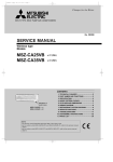
SPLIT-TYPE, HEAT PUMP AIR CONDITIONERS
No. OB245
SERVICE MANUAL
Wireless type
Models
MSZ-G09SV MSZ-G12SV -
E1
(WH)
●
E1
(WH)
●
MUZ-G09SV MUZ-G12SV -
E1
E1
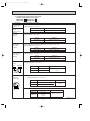
CONTENTS
1. PART NAMES AND FUNCTIONS······················2
2. SPECIFICATION·················································4
3. NOISE CRITERIA CURVES ·······························6
4. OUTLINES AND DIMENSIONS ·························7
5. WIRING DIAGRAM ············································9
6. REFRIGERANT SYSTEM DIAGRAM ··············12
7. PERFORMANCE CURVES ······························14
8. MICROPROCESSOR CONTROL ····················24
9. SERVICE FUNCTIONS ····································38
10. TROUBLESHOOTING······································40
11. DISASSEMBLY INSTRUCTIONS·····················58
12. PARTS LIST······················································62
13. OPTIONAL PARTS···········································66
OB245-1.qxp
1
3/3/00 11:22 AM
Page 2
PART NAMES AND FUNCTIONS
MSZ-G09SV- E1
MSZ-G12SV- E1
INDOOR UNIT
Grille
Air cleaning
filter(white bellows
type)
Air inlet
Deodorizing filter
(gray sponge type)
to Breaker
Air filter
Power supply cord
Front panel
Remote control
receiving section
Vertical vanes
Horizontal vane
Remote
controller
Operation section
Display section
(When the grille is open)
Operation Indicator lamp
Receiving section
Emergency operation switch
MUZ-G09SV- E1
MUZ-G12SV- E1
OUTDOOR UNIT
Air inlet
Piping
Drain hose
Air outlet
Drain outlet
2
OB245-1.qxp
3/3/00 11:22 AM
Page 3
MSZ-G09SV- E1
MSZ-G12SV- E1
REMOTE CONTROLLER
Signal transmitting section
Operation display section
AM
OPERATE /STOP
(ON /OFF)button
PM
CLOCK
6 00 1 1 00
ON/OFF
TOO
WARM
TOO
COOL
OPERATION SELECT button
TEMPERATURE buttons
MODE I FEEL COOL DRY HEAT
FAN
VANE
ECONO COOL
SWING
START
STOP
VANE CONTROL button
FAN SPEED CONTROL button
ECONO COOL button
ON-TIMER button
CLOCK SET button
SWING button
OFF-TIMER button
HR. CLOCK MIN.
HR. button
MIN. button
(TIME SET button)
RESET
3
RESET button
OB245-1.qxp
2
3/3/00 11:22 AM
Page 4
SPECIFICATION
Indoor model
Function
Power supply
kW
Capacity
K /h
Air flow(Hi)
R/h
Dehumidification
A
Power outlet
A
Running current
W
Power input
A(kW)
Auxiliary heater
%
Power factor
A
Starting current
A
Fan motor current
Model
Winding
"
resistance(at20:)
mm
Dimensions WOHOD
kg
Weight
Air direction
dB(A)
Sound level (Hi)
rpm
Fan speed (Hi)
Fan speed regulator
k"
RT11(at25:)
k"
Thermistor RT12(at25:)
k"
RT13(at25:)
Outdoor model
Capacity Outdoor air flow
K /h
A
Electrical Compressor motor current
data
A
Fan motor current
Coefficient of performance(C.O.P)
Model
W
Output
Winding
"
resistance(at20:)
Model
Winding
"
resistance(at20:)
mm
Dimensions WOHOD
kg
Weight
dB(A)
Sound level
rpm
Fan speed
Fan speed regulator
Refrigerant filling
kg
capacity(R-22)
cc
Refrigerating oil (Model)
k"
RT61(at100:)
k"
Thermistor RT62(at0:)
k"
RT64(at70:)
Special
remarks
Compressor
Fan
motor
Special
remarks
3.6 (1.4-5.1)
504
—
2.6 (1.3-3.1)
474
1.2
MSZ-G12SV - E1
Cooling
Heating
Single phase
230V,50Hz
3.5 (0.9-4.0)
4.8 (0.9-6.2)
588
642
—
1.6
10
10
5.50
1140 (430 - 1300)
4.54
940 (440 - 1120)
6.20
1290 (290 - 1390)
—
90
5.50
0.17
RC4V19WHT-BLK 292
BLK-RED 325
850O278O191
9
5
Fan
motor
Electrical
data
Capacity
MSZ-G09SV - E1
Cooling
Heating
Single phase
230V,50Hz
35
1000
36
950
3
10
10
10
MUZ-G09SV - E1
1500
5.08
4.12
0.25
3.16
2.77
KHV-104FGK
900
U-V 2.14
U-W 2.14
V-W 2.14
7.40
1540 (290 - 2090)
—
90
7.40
0.19
RC4V19WHT-BLK 292
BLK-RED 325
850O278O191
10
5
39
1020
1100
3
10
10
10
MUZ-G12SV 1560
5.67
E1
6.87
0.34
2.71
3.12
SHV-130FEA
1100
U-V 0.45
U-W 0.45
V-W 0.45
RA6V18WHT-BLK 279
BLK-RED 198
710(+69)o540o255
28
45
600
1
RA6V28WHT-BLK 201
BLK-RED 350
710(+69)o540o255
34
48
720
1
0.75
1.10
270 (MS56)
13.4
33.2
7.9
350 (MS56)
13.4
33.2
7.9
NOTE : Test conditions are based on ISO (Refrigerant piping length (one way): 5m)
Cooling : Indoor DB27: WB19:
Outdoor DB35: WB24:
Heating : Indoor DB 20: WB -:
Outdoor DB 7: WB 6:
4
OB245-1.qxp
3/3/00 11:22 AM
Page 5
Specifications and rating conditions of main electric parts
INDOOR UNIT
Model
Item
MSZ-G09SV -
E1
MSZ-G12SV -
Indoor fan capacitor
(C11)
1.5+ 440V
Fuse
(F11)
250V 3.15A
Thermal fuse
(F12)
Vane motor
93.5:5A 250V
MP24GA 12V 300"
(MV1, MV2)
Varistor
Solid state relay
(NR11)
ERZV10D471
(SR141)
S201DH1Y
Terminal block
Contactor
E1
(TB)
5P
(52C)
JM1aN-ZTMP-DC12V
136:i3: 2A
Indoor fan motor thermal fuse
OUTDOOR UNIT
Model
Item
Current transformer
MUZ-G09SV -
MUZ-G12SV -
E1
(CT61)
RR-18
Power-facrtor capacitor
(C61)
100+ 420V
165+ 420V
Smoothing capacitor
(C63)
1500+ 420V
2500+ 420V
Outdoor fan capacitor
Diode stack
(C65)
1.8+ 440V
(DS61, DS62)
S25VB80
Fuse
(F801)
250V 2A
Fuse
(F901)
250V 1A
Expansion valve coil
(LEV)
Reactor
(L61)
8A 8mH
15A 4.3mH
Current-detecting resistor (R61, R62)
70m" 5W
100m" 5W
Current-limiting resistor
10" 15W
Solid state relay
(R64)
LAM-MD12ME 12VDC
(SSR61)
10" 20W
TLP3506
Terminal block
(TB2)
4P
Outdoor fan relay
(X61)
G5S-1
Current-limiting relay
R.V. coil
Noise filter
Transistor module
(X64)
G4A-1A
(21S4)
LB8 220-240V AC
EM43261
EM43262
QM15TG-9B
QM20TG-9B
5
E1
OB245-1.qxp
3
3/3/00 11:23 AM
Page 6
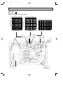
NOISE CRITERIA CURVES
MSZ-G09SV- E1
MUZ-G09SV- E1
NOTCH
Hi
FUNCTION
SPL(dB(A))
NOTCH
LINE
COOLING
Hi
36
Test conditions,
Cooling : DB 27: WB 19:
Heating : DB 20: WB - :
NC-70
60
NC-60
50
NC-50
40
NC-40
30
NC-30
APPROXIMATE
THRESHOLD OF
HEARING FOR
CONTINUOUS
NOISE
63
NC-20
125
250
500
1000
2000
4000
OCTAVE BAND SOUND PRESSURE LEVEL, dB re 0.002 MICRO BAR
OCTAVE BAND SOUND PRESSURE LEVEL, dB re 0.002 MICRO BAR
70
80
70
NC-70
60
NC-60
50
NC-50
40
NC-40
30
NC-30
20
10
8000
APPROXIMATE
THRESHOLD OF
HEARING FOR
CONTINUOUS
NOISE
63
125
NC-20
250
BAND CENTER FREQUENCIES, Hz
1000
2000
4000
8000
MUZ-G12SV- E1
NOTCH
Hi
FUNCTION
SPL(dB(A))
NOTCH
LINE
COOLING
Hi
39
FUNCTION
SPL(dB(A))
LINE
COOLING
48
HEATING
HEATING
Test conditions,
Cooling : DB 27: WB 19:
Heating : DB 20: WB - :
Test conditions,
Cooling : DB 35: WB 24:
Heating : DB 7: WB 6:
90
90
80
70
NC-70
60
NC-60
50
NC-50
40
NC-40
30
NC-30
APPROXIMATE
THRESHOLD OF
HEARING FOR
CONTINUOUS
NOISE
63
125
NC-20
250
500
1000
2000
4000
OCTAVE BAND SOUND PRESSURE LEVEL, dB re 0.002 MICRO BAR
OCTAVE BAND SOUND PRESSURE LEVEL, dB re 0.002 MICRO BAR
500
BAND CENTER FREQUENCIES, Hz
MSZ-G12SV- E1
10
45
90
80
20
LINE
Test conditions,
Cooling : DB 35: WB 24:
Heating : DB 7: WB 6:
90
10
SPL(dB(A))
COOLING
HEATING
HEATING
20
FUNCTION
80
70
NC-70
60
NC-60
50
NC-50
40
NC-40
30
NC-30
20
10
8000
BAND CENTER FREQUENCIES, Hz
APPROXIMATE
THRESHOLD OF
HEARING FOR
CONTINUOUS
NOISE
63
125
NC-20
250
500
1000
2000
4000
BAND CENTER FREQUENCIES, Hz
6
8000
OB245-1.qxp
3/3/00 11:23 AM
4
Page 7
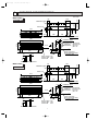
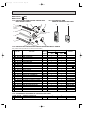
OUTLINES AND DIMENSIONS
Unit: mm
169
4.5
82
INDOOR UNIT
231.5
Installation plate
Indoor unit
271
MSZ-G09SV- E1
81.5
326
42
2.5
41
818
116.5
326
Wall hole [65
5
850
165
17.5
Liquid line [6.35-0.5m
Gas line
[9.52-0.43m
Insulation [37 O.D.
[21 I.D.
Drain hose [16
(Connected part O.D.)
Insulation [28
67
Air out
Power supply cord
Lead to right 1.0m
Lead to left
0.3m
160
56
100
629
{
7 or more
278
Air in
56
Installation plate
189
78
Wireless remote controller
4.5
169
231.5
Installation plate
INDOOR UNIT
Indoor unit
271
82
MSZ-G12SV- E1
81.5
326
42
2.5
41
818
116.5
326
Wall hole [65
5
850
56
629
165
17.5
160
56
100
Air in
Air out
Power supply cord
Lead to right 1.0m
Lead to left
0.3m
Wireless remote controller
7
Installation plate
{
7 or more
278
189
67
78
Liquid line [6.35-0.5m
Gas line
[9.52-0.43m
Insulation [37 O.D.
[21 I.D.
Drain hose [16
(Connected part O.D.)
Insulation [28
OB245-1.qxp
3/3/00 11:23 AM
Page 8
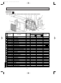
MUZ-G09SV- E1 MUZ-G12SV- E1
Unit: mm
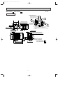
OUTDOOR UNIT
Even if the right/ left sides or
back side are vacant, the top
has to be at least 100mm
unobstructed.
Basically
unobstructed
REQUIRED SPACE
100
mm
Drainage holes [28
32.4
Drainage holes [28
285
320
255
127
92
265
Air in
Drainage holes [28
e
mm
100
or
or m
350
mm
Service panel
20
18
Liquid refrigerant pipe joint
Refrigerant pipe (flared) [6.35
155
90
270
10
3543-
540
Handle
105
Gas refrigerant pipe joint
Refrigerant pipe (flared)
[9.52 (MUZ-G09SV - E1 )
Service port
[12.7 (MUZ-G12SV - E1 )
69
265
or m
ore
W A In case of poorly-ventilated place, the front or the back
has to be at least 200 mm unobstructed.
W B The wall may get dirty in case the air is discharged
toward it.
32.5
40
Air out
or m
or m
However, either the
left/ right sides or
back side should
be unobstructed.
WA
WB
33
4 holes 10o21
ore
mm
100
ore
367
Air in
WA
138
500
Bolt pitch for installation
710
8
3/3/00 11:23 AM
5
Page 9
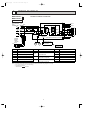
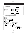
WIRING DIAGRAM
MSZ-G09SVMSZ-G12SV-
MODELS WIRING DIAGRAM
E1
E1
INDOOR UNIT
TO OUTDOOR
UNIT
CONNECTING
12V
L
TB
BRN
WHT
N
1
BLU
2
3
CN201
3
2
1
BLU
BLU
4
52C
TRANS
GRN/YLW
10
CN
121
C11
F11
LD101T
CN
151
NR11
SR141
BLK
3
MV1
BRN
1
2
3
WHT
RED
CN211
CN
ELECTRONIC CONTROL P.C. BOARD 111
RECEIVER
P.C. BOARD
REMOTE
CONTROLLER
CIRCUIT BREAKER
NAME
SYMBOL
NAME
SYMBOL
NAME
VARISTOR
SR141
SOLID STATE RELAY
ROOM TEMPERATURE
TB
TERMINAL BLOCK
THERMAL FUSE (93:)
THERMISTOR
52C
CONTACTOR
HIC1
DC/DC CONVERTER
INDOOR COIL
MF
INDOOR FAN MOTOR(INNER FUSE)
MV1
VANE MOTOR (HORIZONTAL)
MV2
VANE MOTOR (VERTICAL)
C11
INDOOR FAN CAPACITOR
F11
FUSE (3.15A)
F12
NR11
RT11
RT12
THERMISTOR (MAIN)
RT13
INDOOR COIL
THERMISTOR (SUB)
NOTE:1. About the outdoor side electric wiring refer to the outdoor unit electric wiring diagram for servicing.
2. Use copper conductors only. (For field wiring)
3. Symbols below indicate.
/: Terminal block,
: Connector
9
1
2
3
MF
4
5
6
RT11
5
MV2
GRY
YLW
POWER MONITOR,
PE
SYMBOL
RT12
CN112
BLU
BLU
POWER
SUPPLY
CORD
~/N 230V
50Hz
RT13
1
RED
F12
230V~ 2
4
3
2
HIC1
BRN
3
GRN/YLW
OB245-1.qxp
OB245-1.qxp
3/3/00 11:23 AM
MUZ-G09SV-
Page 10
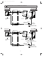
MODEL WIRING DIAGRAM
E1
OUTDOOR UNIT
LDE2
MF61
CN641
1 2 3 4
F801
TR
V
W
EWPBWP EVP BVP EUP BUP
U
BLK
1 2 3
RED
WHT V
W
21S4: heating ON
FROM INDOOR UNIT
CONNECTING
P
WHT
RED
CN722
CN601
3 2 1
N
BLK
WHT
21S4
ELECTRONIC
CONTROL
P.C. BOARD
RED
GRN/YLW
MC
U
RT61 RT62
NAME
SYMBOL
X61
CN771 6 5 4 3 2 1
RED
CN721 2 1
3
R61
BUN
R64
BLU
RELAY
P.C. BOARD
C65
TAB
67
BLU
BLU
TAB64
LEV
1 2
CN724
CN642
F901 LD62
WHT
WHT
T801
6
LD64
BLK
N
-
ORN
4
2
TAB63
YLW
BVN
3
X64
230V ~
TB2
3
RED
C61
4
TAB68
SSR61
12V
TAB65 LDE1
GRN
YLW
RED
C63 +
YLW
RT64
CY63
NOISE FILTER
P.C. BOARD
TAB66
RED
RED
+
BLU
~) (+))
- ~
BLK ( ) (
BLK
TAB69
CT61
(
L61
BLK
~
- ~
( ) (+)
( ) ( )
WHT
CY64
L62
CY62 CY61
ORN
CN725
DS62
RED
DS61
CN723
NR61
GRN
EUN BWN
DSA61
NAME
SYMBOL
NAME
SYMBOL
CT61
CURRENT TRANSFORMER
L61
REACTOR
SSR61
SOLID STATE RELAY
C61
POWER-FACTOR CAPACITOR L62
CMC COIL
TB2
TERMINAL BLOCK
C63
SMOOTHING CAPACITOR
COMPRESSOR
TR
POWER TRANSISTOR MODULE
C65
OUTDOOR FAN CAPACITOR MF61
CY61~64 CAPACITOR
DSA61
SURGE ABSORBER
DS61,62 DIODE STACK
MC
OUTDOOR FAN MOTOR(INNER PROTECTOR) T801
TRANCEFORMER
NR61
VARISTOR
X61
OUTDOOR FAN RELAY
RT61
DEFROST THERMISTOR
X64
CURRENT-LIMITING RELAY
RT62
DISCHARGE TEMPERATURE THERMISTOR 21S4
F801
FUSE (2A)
RT64
FIN TEMPERATURE THERMISTOR
F901
FUSE (1A)
R61
CURRENT-DETECTING RESISTOR
LEV
EXPANSION VALVE COIL
R64
CURRENT-LIMITING RESISTOR
NOTE:1. About the indoor side electric wiring refer to the indoor unit electric wiring diagram for servicing.
2.Use copper conductors only. (For field wiring)
3. Symbols below indicate.
/: Terminal block,
: Connector
10
R.V. COIL
3/3/00 11:23 AM
MUZ-G12SV-
Page 11
MODEL WIRING DIAGRAM
E1
OUTDOOR UNIT
LDE2
GRN
21S4
FROM INDOOR UNIT
CONNECTING
RT64
MF61
F801
R61
P
TR
U
V
W
BLK
CN641
1 2 3 4
1 2 3
BLK
EWP BWP EVP BVP EUP BUP
BUN
N
WHT
RED
CN601
3 2 1
BLU
GRN/YLW
3
ELECTRONIC
CONTROL
P.C. BOARD
CN722
CN771 6 5 4 3 2 1
RED
CN721 2 1
X61
C65
RELAY
P.C BOARD
CN724
TAB
67
CN723
BLU
RED
WHT V
W
21S4: heating ON
MC
U
RT61 RT62
NAME
SYMBOL
1 2
CN642
F901 LD62
WHT
N
WHT
TAB64
LEV
6
LD64
BLK
2
ORN
TAB68
T801
-
WHT
4
230V ~
TAB65 LDE1
GRN
TAB63
YLW
-
C61
4
R62
YLW
YLW
R64
X64
TB2
3
RED
RED
RED
C63 +
+
BLU
3
CT61
SSR61
12V
BLK
BVN
WHT
~
- ~
L61
~
- ~
( ) (+)
( ) ( )
TAB69
BLU
NOISE FILTER
P.C. BOARD TAB66
BLK
( ) (+)
BLK ( ) ( ) RED
RED
CY63
L63
CY64
L62
CY62 CY61
ORN
CN725
DS62
RED
DS61
EUN BWN
DSA61
NR61
OB245-1.qxp
CT61
CURRENT TRANSFORMER
C61
NAME
SYMBOL
NAME
SYMBOL
REACTOR
SSR61
SOLID STATE RELAY
POWER-FACTOR CAPACITOR L62, 63
CMC COIL
TB2
TERMINAL BLOCK
C63
SMOOTHING CAPACITOR
COMPRESSOR
TR
POWER TRANSISTOR MODULE
C65
OUTDOOR FAN CAPACITOR MF61
CY61~64 CAPACITOR
DSA61
SURGE ABSORBER
DS61,62 DIODE STACK
L61
MC
OUTDOOR FAN MOTOR(INNER PROTECTOR) T801
TRANCEFORMER
NR61
VARISTOR
X61
OUTDOOR FAN RELAY
RT61
DEFROST THERMISTOR
X64
CURRENT-LIMITING RELAY
RT62
DISCHARGE TEMPERATURE THERMISTOR 21S4
F801
FUSE (2A)
RT64
FIN TEMPERATURE THERMISTOR
F901
FUSE (1A)
R61, 62
CURRENT-DETECTING RESISTOR
LEV
EXPANSION VALVE COIL
R64
CURRENT-LIMITING RESISTOR
NOTE:1. About the indoor side electric wiring refer to the indoor unit electric wiring diagram for servicing.
2.Use copper conductors only. (For field wiring)
3. Symbols below indicate.
/: Terminal block,
: Connector
11
R.V. COIL
OB245-1.qxp
6
3/3/00 11:23 AM
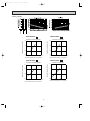
Page 12
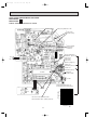
REFRIGERANT SYSTEM DIAGRAM
Unit : mm
MSZ-G09SV -
INDOOR UNIT
Indoor
heat
exchanger
MUZ-G09SV - E1
E1
Refrigerant pipe [9.52
(Option)
(with heat insulator)
Indoor coil
thermistor
RT12(main)
OUTDOOR UNIT
4-way valve
Muffler
Stop valve
(with service port)
Flared connection
Discharge
thermistor
RT62
Indoor coil
thermistor
RT13(sub)
Maffler
Outdoor
heat
exchanger
Compressor
Defrost
thermistor
RT61
Room temperature
thermistor
RT11
Accumulator
Expansion
Capillary tube valve
[3.0✕[1.8✕400
Flared connection
Refrigerant pipe
(Option) [6.35
(with heat insulator)
R.V. coil
heating ON
cooling OFF
Stop valve
(with strainar)
Refrigerant flow in cooling
Refrigerant flow in heating
Unit : mm
MSZ-G12SV -
INDOOR UNIT
Indoor
heat
exchanger
MUZ-G12SV - E1
E1
Refrigerant pipe [12.7
(Option)
(with heat insulator)
Indoor coil
thermistor
RT12(main)
OUTDOOR UNIT
4-way valve
Muffler
Stop valve
(with service port)
Flared connection
Discharge
thermistor
RT62
Indoor coil
thermistor
RT13(sub)
Maffler
Outdoor
heat
exchanger
Compressor
Defrost
thermistor
RT61
Room temperature
thermistor
RT11
Accumulator
Capillary
tube
[3.0✕[2.0✕300
Expansion
Capillary tube valve
[3.0✕[2.0✕200
Flared connection
Refrigerant pipe
(Option) [6.35
(with heat insulator)
Capillary
tube
[3.0✕[2.0✕300
Stop valve
(with strainar)
R.V. coil
heating ON
cooling OFF
Refrigerant flow in cooling
Refrigerant flow in heating
12
OB245-1.qxp
3/3/00 11:23 AM
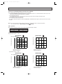
Page 13
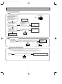
MAX. REFRIGERANT PIPING LENGTH
Refrigerant piping
Piping size O.D : mm
Max. length : m
Model
MSZ-G09SV -
E1
MSZ-G12SV -
E1
A
Gas
12
9.52
15
12.7
Length of connecting pipe : m
Liquid
Indoor unit
6.35
Gas 0.43
Liquid 0.5
Outdoor unit
MAX. HEIGHT DIFFERENCE
Indoor
unit
w Max. Height
difference 8m
(MSZ-G09SV- E1 )
w Max. Height
difference 10m
(MSZ-G12SV- E1 )
Refrigerant Piping
Max. length
A
Outdoor unit
w Height difference should be within
8m(MSZ-G09SV- E1 )/ 10m(MSZ-G12SV- E1 )
regardless of which unit,
indoor or outdoor position is high.
ADDITIONAL REFRIGERANT CHARGE (R-22:g)
Model
Refrigerant piping length (one way)
Outdoor unit
precharged
5m
6m
7m
8m
9m
10m
11m
12m
MSZ-G09SV -
E1
750
0
30
60
90
120
150
180
210
MSZ-G12SV -
E1
1100
0
30
60
90
120
150
180
210
13m
14m
15m
240
270
300
Calculation : Xg=30g/mo(Refrigerant piping length(m) - 5)
13
OB245-1.qxp
7
3/3/00 11:23 AM
Page 14
PERFORMANCE CURVES
MSZ-G09SV - E1
MSZ-G12SV - E1
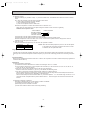
The standard data contained in these specifications apply only to the operation of the air conditioner under normal conditions.
Since operating conditions vary according to the areas where these units are installed. The following information has been
provided to clarify the operating characteristics of the air conditioner under the conditions indicated by the performance curve.
(1) GUARANTEED VOLTAGE
Rated voltage : ±10% (207 ~ 253V),50Hz
(2) AIR FLOW
Air flow should be set at MAX.
(3) MAIN READINGS
(1) Indoor intake air wet-bulb temperature
(2) Indoor outlet air wet-bulb temperature
(3) Outdoor intake air dry-bulb temperature
(4) Total input
(5) Indoor intake air dry-bulb temperature
(6) Outdoor intake air wet-bulb temperature
(7) Total input
::WB
::WB
::DB
:W
::DB
::WB
:W
}
}
Cooling
Heating
Indoor air wet/dry-bulb temperature difference on the left side of the chart on page 15 and 16 shows the difference
between the indoor intake air wet/dry-bulb temperature and the indoor outlet air wet/dry-bulb temperature for your reference at service.
How to measure the indoor air wet-bulb/ dry-bulb temperature difference
1.
2.
3.
4.
5.
6.
7.
Attach at least 2 sets of wet-and dry-bulb thermometers to the indoor air intake as shown in the figure, and at least 2 sets
of wet-and dry-bulb thermometers to the indoor air outlet. The thermometers must be attached to the position where air
speed is high.
Attach at least 2 sets of wet-and dry-bulb thermometers to the outdoor air intake.
Cover the thermometers to prevent direct rays of the sun.
Check that the air filter is cleaned.
Open windows and doors of room.
Press the EMERGENCY OPERATION switch once (twice) to start the EMERGENCY COOL (HEAT) MODE.
When system stabilizes after more than 15 minutes, measure temperature and take an average temperature.
10 minutes later, measure temperature again and check that the temperature does not change.
OUTDOOR UNIT
INDOOR UNIT
14
3/3/00 11:23 AM
Page 15
11.5
11.6
10.5
10.6
9.6
9.6
8.6
8.7
7.7
7.8
6.8
6.9
MSZ-G12SV- E1
Cooling capacity
MSZ-G09SV- E1
MUZ-G09SV - E1
MUZ-G09SV - E1
Correction of Cooling capacity
Correction of total input
1.5
Capacity correction factors
Capacity correction factors
1.5
1.0
0.5
0.0
0
50
100
1.0
0.5
0.0
0
150(Hz)
The operational frequency of compressor
100
150(Hz)
MUZ-G12SV - E1
Correction of total input
Correction of Cooling capacity
1.5
Capacity correction factors
1.5
1.0
0.5
0.0
0
50
The operational frequency of compressor
MUZ-G12SV - E1
Capacity correction factors
OB245-1.qxp
50
100
150(Hz)
1.0
0.5
0.0
0
50
100
150
The operational frequency of compressor
The operational frequency of compressor
15
OB245-1.qxp
3/3/00 11:23 AM
Page 16
Heating capacity
28.0
29.3
25.9
27.1
23.7
24.8
21.6
22.6
19.4
20.3
17.2
18.1
15.1
15.8
12.9
13.5
MSZ-G09SV- E1
MSZ-G12SV- E1
NOTE:The above curves are for the heating operation without any frost.
MUZ-G09SV - E1
MUZ-G09SV - E1
Correction of Heating capacity
Correction of total input
1.5
Capacity correction factors
Capacity correction factors
1.5
1.0
0.5
0.0
0
50
100
1.0
0.5
0.0
0
150(Hz)
The operational frequency of compressor
150(Hz)
MUZ-G12SV - E1
MUZ-G12SV - E1
Correction of total input
1.5
1.5
Capacity correction factors
Capacity correction factors
100
The operational frequency of compressor
Correction of Heating capacity
1.0
0.5
0.0
0
50
50
100
150(Hz)
The operational frequency of compressor
1.0
0.5
0.0
0
50
100
150(Hz)
The operational frequency of compressor
16
3/3/00 11:24 AM
Page 17
OUTDOOR LOW PRESSURE AND OUTDOOR UNIT CURRENT
How to operate with fixed operational frequency of the compressor.
1. Press the EMERGENCY OPERATION switch on the front of the indoor unit , and select either the COOL mode or the
HEAT mode before starting to operate the air conditioner.
2. The compressor starts up.
The operational frequency of the compressor is 82Hz in the COOL mode and 58Hz in the HEAT mode.
3. The fan speed of the indoor unit is Hi.
4. This operation continues for 30minutes.
5. In order to release this operation, press the EMERGENCY OPERATION switch again, press any button on the remote
controller.
NOTE : The unit of pressure has been changed to MPa on the international system of units(SI unit system).
f [Gauge])
The conversion factor is: 1(MPa [Gauge]) =10.2(kgf/f
COOL operation
1 Both indoor and outdoor unit are under the same temperature/humidity condition.
Dry-bulb temperature
20
25
30
2 Air flow should be set at Hi.
Relative humidity(%)
50
60
70
3 Operational frequency : 79Hz
MUZ-G09SV - E1
MUZ-G09SV - E1
8
0.8
7
0.7
6
0.6
5
0.5
4
0.4
3
0.3
2
0.2
15
Outdoor unit current (A)
Outdoor low pressure
(kgf/F [Gauge])(MPa [Gauge])
79Hz
18 20
50
25
60
30 32
70(%)
7
6
79Hz
5
230V
4
3
15
35(:)
Ambient temperature(:)
Ambient humidity(%)
18 20
50
25
60
30 32 35(:)
70(%)
Ambient temperature(:)
Ambient humidity(%)
Operational frequency : 85Hz
MUZ-G12SV - E1
MUZ-G12SV - E1
8
0.8
7
0.7
Outdoor unit current (A)
(kgf/F [Gauge])(MPa [Gauge])
Outdoor low pressure
OB245-1.qxp
85Hz
6
0.6
5
0.5
4
0.4
3
0.3
2
0.2
15
18 20
50
25
60
Ambient temperature(:)
Ambient humidity(%)
30 32
70(%)
7
5
4
3
15
35(:)
85Hz
230V
6
18 20
50
25
60
Ambient temperature(:)
Ambient humidity(%)
17
30 32 35(:)
70(%)
OB245-1.qxp
3/3/00 11:24 AM
Page 18
HEAT operation
Condition Indoor : Dry bulb temperature 20.0:
Wet bulb temperature 14.5:
Outdoor : Dry bulb temperature 2 7 15 20.0:
Wet bulb temperature 1 6 12 14.5:
MUZ-G09SV - E1
MUZ-G12SV - E1
6.0
5.5
5.0
58Hz
230V
4.5
4.0
3.5
3.0
2
5
10
15
20
Ambient temperature(:)
25
Outdoor unit current (A)
Outdoor unit current (A)
6.0
5.5
5.0
58Hz
230V
4.5
4.0
3.5
3.0
2
5
10
15
20
Ambient temperature(:)
18
25
OB245-1.qxp
3/3/00 11:24 AM
Page 19
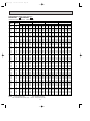
PERFORMANCE DATA COOL operation
MSZ-G09SV - E1 MUZ-G09SV - E1
CAPACITY:2.6(KW) SHF:0.68
INDOOR INDOOR
DB(;)
WB(;)
21
21
22
22
22
23
23
23
24
24
24
24
25
25
25
25
26
26
26
26
26
27
27
27
27
27
28
28
28
28
28
29
29
29
29
29
30
30
30
30
30
31
31
31
31
31
32
32
32
32
32
NOTE
18
20
18
20
22
18
20
22
18
20
22
24
18
20
22
24
18
20
22
24
26
18
20
22
24
26
18
20
22
24
26
18
20
22
24
26
18
20
22
24
26
18
20
22
24
26
18
20
22
24
26
Q
3.06
3.19
3.06
3.19
3.32
3.06
3.19
3.32
3.06
3.19
3.32
3.48
3.06
3.19
3.32
3.48
3.06
3.19
3.32
3.48
3.59
3.06
3.19
3.32
3.48
3.59
3.06
3.19
3.32
3.48
3.59
3.06
3.19
3.32
3.48
3.59
3.06
3.19
3.32
3.48
3.59
3.06
3.19
3.32
3.48
3.59
3.06
3.19
3.32
3.48
3.59
SHC
1.53
1.21
1.65
1.34
0.99
1.77
1.47
1.13
1.89
1.59
1.26
0.91
2.02
1.72
1.39
1.05
2.14
1.85
1.52
1.18
0.79
2.26
1.97
1.66
1.32
0.93
2.38
2.10
1.79
1.46
1.08
2.51
2.23
1.92
1.60
1.22
2.63
2.36
2.06
1.74
1.36
2.75
2.48
2.19
1.88
1.51
2.87
2.61
2.32
2.02
1.65
INPUT:940(W)
OUTDOOR
21
25
SHF INPUT Q SHC SHF INPUT
0.50 752 2.93 1.46 0.50 790
0.38 790 3.06 1.16 0.38 837
0.54 752 2.93 1.58 0.54 790
0.42 790 3.06 1.28 0.42 837
0.30 818 3.20 0.96 0.30 870
0.58 752 2.93 1.70 0.58 790
0.46 790 3.06 1.41 0.46 837
0.34 818 3.20 1.09 0.34 870
0.62 752 2.93 1.81 0.62 790
0.50 790 3.06 1.53 0.50 837
0.38 818 3.20 1.22 0.38 870
0.26 855 3.35 0.87 0.26 902
0.66 752 2.93 1.93 0.66 790
0.54 790 3.06 1.65 0.54 837
0.42 818 3.20 1.34 0.42 870
0.30 855 3.35 1.01 0.30 902
0.70 752 2.93 2.05 0.70 790
0.58 790 3.06 1.77 0.58 837
0.46 818 3.20 1.47 0.46 870
0.34 855 3.35 1.14 0.34 902
0.22 902 3.48 0.77 0.22 949
0.74 752 2.93 2.16 0.74 790
0.62 790 3.06 1.89 0.62 837
0.50 818 3.20 1.60 0.50 870
0.38 855 3.35 1.27 0.38 902
0.26 902 3.48 0.91 0.26 949
0.78 752 2.93 2.28 0.78 790
0.66 790 3.06 2.02 0.66 837
0.54 818 3.20 1.73 0.54 870
0.42 855 3.35 1.41 0.42 902
0.30 902 3.48 1.05 0.30 949
0.82 752 2.93 2.40 0.82 790
0.70 790 3.06 2.14 0.70 837
0.58 818 3.20 1.85 0.58 870
0.46 855 3.35 1.54 0.46 902
0.34 902 3.48 1.18 0.34 949
0.86 752 2.93 2.52 0.86 790
0.74 790 3.06 2.26 0.74 837
0.62 818 3.20 1.98 0.62 870
0.50 855 3.35 1.68 0.50 902
0.38 902 3.48 1.32 0.38 949
0.90 752 2.93 2.63 0.90 790
0.78 790 3.06 2.38 0.78 837
0.66 818 3.20 2.11 0.66 870
0.54 855 3.35 1.81 0.54 902
0.42 902 3.48 1.46 0.42 949
0.94 752 2.93 2.75 0.94 790
0.82 790 3.06 2.51 0.82 837
0.70 818 3.20 2.24 0.70 870
0.58 855 3.35 1.95 0.58 902
0.46 902 3.48 1.60 0.46 949
Q :Total capacity (kW)
SHC :Sensible heat capacity (kW)
DB(;)
Q
2.81
2.96
2.81
2.96
3.12
2.81
2.96
3.12
2.81
2.96
3.12
3.28
2.81
2.96
3.12
3.28
2.81
2.96
3.12
3.28
3.43
2.81
2.96
3.12
3.28
3.43
2.81
2.96
3.12
3.28
3.43
2.81
2.96
3.12
3.28
3.43
2.81
2.96
3.12
3.28
3.43
2.81
2.96
3.12
3.28
3.43
2.81
2.96
3.12
3.28
3.43
SHF :Sensible heat factor
INPUT :Total power input (W)
19
SHC
1.40
1.13
1.52
1.24
0.94
1.63
1.36
1.06
1.74
1.48
1.19
0.85
1.85
1.60
1.31
0.98
1.97
1.72
1.44
1.11
0.76
2.08
1.84
1.56
1.24
0.89
2.19
1.96
1.68
1.38
1.03
2.30
2.07
1.81
1.51
1.17
2.41
2.19
1.93
1.64
1.30
2.53
2.31
2.06
1.77
1.44
2.64
2.43
2.18
1.90
1.58
27
30
SHF INPUT Q SHC SHF INPUT
0.50 827 2.70 1.35 0.50 865
0.38 855 2.86 1.09 0.38 893
0.54 827 2.70 1.46 0.54 865
0.42 855 2.86 1.20 0.42 893
0.30 893 2.99 0.90 0.30 931
0.58 827 2.70 1.57 0.58 865
0.46 855 2.86 1.32 0.46 893
0.34 893 2.99 1.02 0.34 931
0.62 827 2.70 1.68 0.62 865
0.50 855 2.86 1.43 0.50 893
0.38 893 2.99 1.14 0.38 931
0.26 931 3.17 0.82 0.26 978
0.66 827 2.70 1.78 0.66 865
0.54 855 2.86 1.54 0.54 893
0.42 893 2.99 1.26 0.42 931
0.30 931 3.17 0.95 0.30 978
0.70 827 2.70 1.89 0.70 865
0.58 855 2.86 1.66 0.58 893
0.46 893 2.99 1.38 0.46 931
0.34 931 3.17 1.08 0.34 978
0.22 978 3.33 0.73 0.22 1006
0.74 827 2.70 2.00 0.74 865
0.62 855 2.86 1.77 0.62 893
0.50 893 2.99 1.50 0.50 931
0.38 931 3.17 1.21 0.38 978
0.26 978 3.33 0.87 0.26 1006
0.78 827 2.70 2.11 0.78 865
0.66 855 2.86 1.89 0.66 893
0.54 893 2.99 1.61 0.54 931
0.42 931 3.17 1.33 0.42 978
0.30 978 3.33 1.00 0.30 1006
0.82 827 2.70 2.22 0.82 865
0.70 855 2.86 2.00 0.70 893
0.58 893 2.99 1.73 0.58 931
0.46 931 3.17 1.46 0.46 978
0.34 978 3.33 1.13 0.34 1006
0.86 827 2.70 2.33 0.86 865
0.74 855 2.86 2.12 0.74 893
0.62 893 2.99 1.85 0.62 931
0.50 931 3.17 1.59 0.50 978
0.38 978 3.33 1.26 0.38 1006
0.90 827 2.70 2.43 0.90 865
0.78 855 2.86 2.23 0.78 893
0.66 893 2.99 1.97 0.66 931
0.54 931 3.17 1.71 0.54 978
0.42 978 3.33 1.40 0.42 1006
0.94 827 2.70 2.54 0.94 865
0.82 855 2.86 2.35 0.82 893
0.70 893 2.99 2.09 0.70 931
0.58 931 3.17 1.84 0.58 978
0.46 978 3.33 1.53 0.46 1006
OB245-1.qxp
3/3/00 11:24 AM
Page 20
PERFORMANCE DATA COOL operation
MSZ-G09SV - E1 MUZ-G09SV - E1
CAPACITY:2.6(KW)
INDOOR INDOOR
DB(;)
WB(;)
21
21
22
22
22
23
23
23
24
24
24
24
25
25
25
25
26
26
26
26
26
27
27
27
27
27
28
28
28
28
28
29
29
29
29
29
30
30
30
30
30
31
31
31
31
31
32
32
32
32
32
NOTE
18
20
18
20
22
18
20
22
18
20
22
24
18
20
22
24
18
20
22
24
26
18
20
22
24
26
18
20
22
24
26
18
20
22
24
26
18
20
22
24
26
18
20
22
24
26
18
20
22
24
26
SHF:0.68
Q
2.55
2.68
2.55
2.68
2.83
2.55
2.68
2.83
2.55
2.68
2.83
2.99
2.55
2.68
2.83
2.99
2.55
2.68
2.83
2.99
3.15
2.55
2.68
2.83
2.99
3.15
2.55
2.68
2.83
2.99
3.15
2.55
2.68
2.83
2.99
3.15
2.55
2.68
2.83
2.99
3.15
2.55
2.68
2.83
2.99
3.15
2.55
2.68
2.83
2.99
3.15
INPUT:940(W)
OUTDOOR
35
40
SHC SHF INPUT Q SHC SHF INPUT
1.27 0.50 921 2.34 1.17 0.50 978
1.02 0.38 959 2.50 0.95 0.38 1006
1.38 0.54 921 2.34 1.26 0.54 978
1.12 0.42 959 2.50 1.05 0.42 1006
0.85 0.30 996 2.65 0.80 0.30 1053
1.48 0.58 921 2.34 1.36 0.58 978
1.23 0.46 959 2.50 1.15 0.46 1006
0.96 0.34 996 2.65 0.90 0.34 1053
1.58 0.62 921 2.34 1.45 0.62 978
1.34 0.50 959 2.50 1.25 0.50 1006
1.08 0.38 996 2.65 1.01 0.38 1053
0.78 0.26 1034 2.81 0.73 0.26 1081
1.68 0.66 921 2.34 1.54 0.66 978
1.45 0.54 959 2.50 1.35 0.54 1006
1.19 0.42 996 2.65 1.11 0.42 1053
0.90 0.30 1034 2.81 0.84 0.30 1081
1.78 0.70 921 2.34 1.64 0.70 978
1.55 0.58 959 2.50 1.45 0.58 1006
1.30 0.46 996 2.65 1.22 0.46 1053
1.02 0.34 1034 2.81 0.95 0.34 1081
0.69 0.22 1072 2.96 0.65 0.22 1119
1.89 0.74 921 2.34 1.73 0.74 978
1.66 0.62 959 2.50 1.55 0.62 1006
1.42 0.50 996 2.65 1.33 0.50 1053
1.14 0.38 1034 2.81 1.07 0.38 1081
0.82 0.26 1072 2.96 0.77 0.26 1119
1.99 0.78 921 2.34 1.83 0.78 978
1.77 0.66 959 2.50 1.65 0.66 1006
1.53 0.54 996 2.65 1.43 0.54 1053
1.26 0.42 1034 2.81 1.18 0.42 1081
0.94 0.30 1072 2.96 0.89 0.30 1119
2.09 0.82 921 2.34 1.92 0.82 978
1.87 0.70 959 2.50 1.75 0.70 1006
1.64 0.58 996 2.65 1.54 0.58 1053
1.38 0.46 1034 2.81 1.29 0.46 1081
1.07 0.34 1072 2.96 1.01 0.34 1119
2.19 0.86 921 2.34 2.01 0.86 978
1.98 0.74 959 2.50 1.85 0.74 1006
1.76 0.62 996 2.65 1.64 0.62 1053
1.50 0.50 1034 2.81 1.40 0.50 1081
1.20 0.38 1072 2.96 1.13 0.38 1119
2.29 0.90 921 2.34 2.11 0.90 978
2.09 0.78 959 2.50 1.95 0.78 1006
1.87 0.66 996 2.65 1.75 0.66 1053
1.61 0.54 1034 2.81 1.52 0.54 1081
1.32 0.42 1072 2.96 1.24 0.42 1119
2.40 0.94 921 2.34 2.20 0.94 978
2.20 0.82 959 2.50 2.05 0.82 1006
1.98 0.70 996 2.65 1.86 0.70 1053
1.73 0.58 1034 2.81 1.63 0.58 1081
1.45 0.46 1072 2.96 1.36 0.46 1119
Q :Total capacity (kW)
SHC :Sensible heat capacity (kW)
SHF :Sensible heat factor
INPUT :Total power input (W)
20
DB(;)
Q
2.25
2.41
2.25
2.41
2.56
2.25
2.41
2.56
2.25
2.41
2.56
2.73
2.25
2.41
2.56
2.73
2.25
2.41
2.56
2.73
2.87
2.25
2.41
2.56
2.73
2.87
2.25
2.41
2.56
2.73
2.87
2.25
2.41
2.56
2.73
2.87
2.25
2.41
2.56
2.73
2.87
2.25
2.41
2.56
2.73
2.87
2.25
2.41
2.56
2.73
2.87
SHC
1.12
0.91
1.21
1.01
0.77
1.30
1.11
0.87
1.39
1.20
0.97
0.71
1.48
1.30
1.08
0.82
1.57
1.39
1.18
0.93
0.63
1.66
1.49
1.28
1.04
0.75
1.75
1.59
1.38
1.15
0.86
1.84
1.68
1.49
1.26
0.98
1.93
1.78
1.59
1.37
1.09
2.02
1.88
1.69
1.47
1.21
2.11
1.97
1.79
1.58
1.32
43
46
SHF INPUT Q SHC SHF INPUT
0.50 996 2.16 1.08 0.50 1015
0.38 1034 2.31 0.88 0.38 1062
0.54 996 2.16 1.17 0.54 1015
0.42 1034 2.31 0.97 0.42 1062
0.30 1072 2.47 0.74 0.30 1090
0.58 996 2.16 1.25 0.58 1015
0.46 1034 2.31 1.06 0.46 1062
0.34 1072 2.47 0.84 0.34 1090
0.62 996 2.16 1.34 0.62 1015
0.50 1034 2.31 1.16 0.50 1062
0.38 1072 2.47 0.94 0.38 1090
0.26 1105 2.65 0.69 0.26 1128
0.66 996 2.16 1.42 0.66 1015
0.54 1034 2.31 1.25 0.54 1062
0.42 1072 2.47 1.04 0.42 1090
0.30 1105 2.65 0.80 0.30 1128
0.70 996 2.16 1.51 0.70 1015
0.58 1034 2.31 1.34 0.58 1062
0.46 1072 2.47 1.14 0.46 1090
0.34 1105 2.65 0.90 0.34 1128
0.22 1142 2.78 0.61 0.22 1166
0.74 996 2.16 1.60 0.74 1015
0.62 1034 2.31 1.43 0.62 1062
0.50 1072 2.47 1.24 0.50 1090
0.38 1105 2.65 1.01 0.38 1128
0.26 1142 2.78 0.72 0.26 1166
0.78 996 2.16 1.68 0.78 1015
0.66 1034 2.31 1.53 0.66 1062
0.54 1072 2.47 1.33 0.54 1090
0.42 1105 2.65 1.11 0.42 1128
0.30 1142 2.78 0.83 0.30 1166
0.82 996 2.16 1.77 0.82 1015
0.70 1034 2.31 1.62 0.70 1062
0.58 1072 2.47 1.43 0.58 1090
0.46 1105 2.65 1.22 0.46 1128
0.34 1142 2.78 0.95 0.34 1166
0.86 996 2.16 1.86 0.86 1015
0.74 1034 2.31 1.71 0.74 1062
0.62 1072 2.47 1.53 0.62 1090
0.50 1105 2.65 1.33 0.50 1128
0.38 1142 2.78 1.06 0.38 1166
0.90 996 2.16 1.94 0.90 1015
0.78 1034 2.31 1.80 0.78 1062
0.66 1072 2.47 1.63 0.66 1090
0.54 1105 2.65 1.43 0.54 1128
0.42 1142 2.78 1.17 0.42 1166
0.94 996 2.16 2.03 0.94 1015
0.82 1034 2.31 1.90 0.82 1062
0.70 1072 2.47 1.73 0.70 1090
0.58 1105 2.65 1.54 0.58 1128
0.46 1142 2.78 1.28 0.46 1166
OB245-1.qxp
3/3/00 11:24 AM
Page 21
PERFORMANCE DATA COOL operation
MSZ-G12SV - E1 MUZ-G12SV - E1
CAPACITY:3.5(KW)
INDOOR INDOOR
DB(;)
WB(;)
21
21
22
22
22
23
23
23
24
24
24
24
25
25
25
25
26
26
26
26
26
27
27
27
27
27
28
28
28
28
28
29
29
29
29
29
30
30
30
30
30
31
31
31
31
31
32
32
32
32
32
NOTE
18
20
18
20
22
18
20
22
18
20
22
24
18
20
22
24
18
20
22
24
26
18
20
22
24
26
18
20
22
24
26
18
20
22
24
26
18
20
22
24
26
18
20
22
24
26
18
20
22
24
26
SHF:0.67
Q
4.11
4.29
4.11
4.29
4.46
4.11
4.29
4.46
4.11
4.29
4.46
4.69
4.11
4.29
4.46
4.69
4.11
4.29
4.46
4.69
4.83
4.11
4.29
4.46
4.69
4.83
4.11
4.29
4.46
4.69
4.83
4.11
4.29
4.46
4.69
4.83
4.11
4.29
4.46
4.69
4.83
4.11
4.29
4.46
4.69
4.83
4.11
4.29
4.46
4.69
4.83
INPUT:1290(W)
OUTDOOR DB(;)
21
25
27
30
SHC SHF INPUT Q SHC SHF INPUT Q SHC SHF INPUT Q SHC SHF INPUT
2.02 0.49 1032 3.94 1.93 0.49 1084 3.78 1.85 0.49 1135 3.64 1.78 0.49 1187
1.59 0.37 1084 4.11 1.52 0.37 1148 3.99 1.48 0.37 1174 3.85 1.42 0.37 1226
2.18 0.53 1032 3.94 2.09 0.53 1084 3.78 2.00 0.53 1135 3.64 1.93 0.53 1187
1.76 0.41 1084 4.11 1.69 0.41 1148 3.99 1.64 0.41 1174 3.85 1.58 0.41 1226
1.29 0.29 1122 4.31 1.25 0.29 1193 4.20 1.22 0.29 1226 4.03 1.17 0.29 1277
2.34 0.57 1032 3.94 2.24 0.57 1084 3.78 2.15 0.57 1135 3.64 2.07 0.57 1187
1.93 0.45 1084 4.11 1.85 0.45 1148 3.99 1.80 0.45 1174 3.85 1.73 0.45 1226
1.47 0.33 1122 4.31 1.42 0.33 1193 4.20 1.39 0.33 1226 4.03 1.33 0.33 1277
2.51 0.61 1032 3.94 2.40 0.61 1084 3.78 2.31 0.61 1135 3.64 2.22 0.61 1187
2.10 0.49 1084 4.11 2.02 0.49 1148 3.99 1.96 0.49 1174 3.85 1.89 0.49 1226
1.65 0.37 1122 4.31 1.59 0.37 1193 4.20 1.55 0.37 1226 4.03 1.49 0.37 1277
1.17 0.25 1174 4.52 1.13 0.25 1238 4.41 1.10 0.25 1277 4.27 1.07 0.25 1342
2.67 0.65 1032 3.94 2.56 0.65 1084 3.78 2.46 0.65 1135 3.64 2.37 0.65 1187
2.27 0.53 1084 4.11 2.18 0.53 1148 3.99 2.11 0.53 1174 3.85 2.04 0.53 1226
1.83 0.41 1122 4.31 1.77 0.41 1193 4.20 1.72 0.41 1226 4.03 1.65 0.41 1277
1.36 0.29 1174 4.52 1.31 0.29 1238 4.41 1.28 0.29 1277 4.27 1.24 0.29 1342
2.84 0.69 1032 3.94 2.72 0.69 1084 3.78 2.61 0.69 1135 3.64 2.51 0.69 1187
2.44 0.57 1084 4.11 2.34 0.57 1148 3.99 2.27 0.57 1174 3.85 2.19 0.57 1226
2.01 0.45 1122 4.31 1.94 0.45 1193 4.20 1.89 0.45 1226 4.03 1.81 0.45 1277
1.55 0.33 1174 4.52 1.49 0.33 1238 4.41 1.46 0.33 1277 4.27 1.41 0.33 1342
1.01 0.21 1238 4.69 0.98 0.21 1303 4.62 0.97 0.21 1342 4.48 0.94 0.21 1380
3.00 0.73 1032 3.94 2.87 0.73 1084 3.78 2.76 0.73 1135 3.64 2.66 0.73 1187
2.62 0.61 1084 4.11 2.51 0.61 1148 3.99 2.43 0.61 1174 3.85 2.35 0.61 1226
2.19 0.49 1122 4.31 2.11 0.49 1193 4.20 2.06 0.49 1226 4.03 1.97 0.49 1277
1.74 0.37 1174 4.52 1.67 0.37 1238 4.41 1.63 0.37 1277 4.27 1.58 0.37 1342
1.21 0.25 1238 4.69 1.17 0.25 1303 4.62 1.16 0.25 1342 4.48 1.12 0.25 1380
3.17 0.77 1032 3.94 3.03 0.77 1084 3.78 2.91 0.77 1135 3.64 2.80 0.77 1187
2.79 0.65 1084 4.11 2.67 0.65 1148 3.99 2.59 0.65 1174 3.85 2.50 0.65 1226
2.37 0.53 1122 4.31 2.28 0.53 1193 4.20 2.23 0.53 1226 4.03 2.13 0.53 1277
1.92 0.41 1174 4.52 1.85 0.41 1238 4.41 1.81 0.41 1277 4.27 1.75 0.41 1342
1.40 0.29 1238 4.69 1.36 0.29 1303 4.62 1.34 0.29 1342 4.48 1.30 0.29 1380
3.33 0.81 1032 3.94 3.19 0.81 1084 3.78 3.06 0.81 1135 3.64 2.95 0.81 1187
2.96 0.69 1084 4.11 2.84 0.69 1148 3.99 2.75 0.69 1174 3.85 2.66 0.69 1226
2.54 0.57 1122 4.31 2.45 0.57 1193 4.20 2.39 0.57 1226 4.03 2.29 0.57 1277
2.11 0.45 1174 4.52 2.03 0.45 1238 4.41 1.98 0.45 1277 4.27 1.92 0.45 1342
1.59 0.33 1238 4.69 1.55 0.33 1303 4.62 1.52 0.33 1342 4.48 1.48 0.33 1380
3.50 0.85 1032 3.94 3.35 0.85 1084 3.78 3.21 0.85 1135 3.64 3.09 0.85 1187
3.13 0.73 1084 4.11 3.00 0.73 1148 3.99 2.91 0.73 1174 3.85 2.81 0.73 1226
2.72 0.61 1122 4.31 2.63 0.61 1193 4.20 2.56 0.61 1226 4.03 2.46 0.61 1277
2.30 0.49 1174 4.52 2.21 0.49 1238 4.41 2.16 0.49 1277 4.27 2.09 0.49 1342
1.79 0.37 1238 4.69 1.74 0.37 1303 4.62 1.71 0.37 1342 4.48 1.66 0.37 1380
3.66 0.89 1032 3.94 3.50 0.89 1084 3.78 3.36 0.89 1135 3.64 3.24 0.89 1187
3.30 0.77 1084 4.11 3.17 0.77 1148 3.99 3.07 0.77 1174 3.85 2.96 0.77 1226
2.90 0.65 1122 4.31 2.80 0.65 1193 4.20 2.73 0.65 1226 4.03 2.62 0.65 1277
2.49 0.53 1174 4.52 2.39 0.53 1238 4.41 2.34 0.53 1277 4.27 2.26 0.53 1342
1.98 0.41 1238 4.69 1.92 0.41 1303 4.62 1.89 0.41 1342 4.48 1.84 0.41 1380
3.82 0.93 1032 3.94 3.66 0.93 1084 3.78 3.52 0.93 1135 3.64 3.39 0.93 1187
3.47 0.81 1084 4.11 3.33 0.81 1148 3.99 3.23 0.81 1174 3.85 3.12 0.81 1226
3.08 0.69 1122 4.31 2.97 0.69 1193 4.20 2.90 0.69 1226 4.03 2.78 0.69 1277
2.67 0.57 1174 4.52 2.57 0.57 1238 4.41 2.51 0.57 1277 4.27 2.43 0.57 1342
2.17 0.45 1238 4.69 2.11 0.45 1303 4.62 2.08 0.45 1342 4.48 2.02 0.45 1380
Q :Total capacity (kW)
SHC :Sensible heat capacity (kW)
SHF :Sensible heat factor
INPUT :Total power input (W)
21
OB245-1.qxp
3/3/00 11:24 AM
Page 22
PERFORMANCE DATA COOL operation
MSZ-G12SV - E1 MUZ-G12SV - E1
CAPACITY:3.5(KW)
INDOOR INDOOR
DB(;)
WB(;)
21
21
22
22
22
23
23
23
24
24
24
24
25
25
25
25
26
26
26
26
26
27
27
27
27
27
28
28
28
28
28
29
29
29
29
29
30
30
30
30
30
31
31
31
31
31
32
32
32
32
32
NOTE
18
20
18
20
22
18
20
22
18
20
22
24
18
20
22
24
18
20
22
24
26
18
20
22
24
26
18
20
22
24
26
18
20
22
24
26
18
20
22
24
26
18
20
22
24
26
18
20
22
24
26
SHF:0.67
Q
3.43
3.61
3.43
3.61
3.82
3.43
3.61
3.82
3.43
3.61
3.82
4.03
3.43
3.61
3.82
4.03
3.43
3.61
3.82
4.03
4.24
3.43
3.61
3.82
4.03
4.24
3.43
3.61
3.82
4.03
4.24
3.43
3.61
3.82
4.03
4.24
3.43
3.61
3.82
4.03
4.24
3.43
3.61
3.82
4.03
4.24
3.43
3.61
3.82
4.03
4.24
INPUT:1290(W)
OUTDOOR DB(;)
35
40
43
46
SHC SHF INPUT Q SHC SHF INPUT Q SHC SHF INPUT Q SHC SHF INPUT
1.68 0.49 1264 3.15 1.54 0.49 1342 3.03 1.48 0.49 1367 2.91 1.42 0.49 1393
1.33 0.37 1316 3.36 1.24 0.37 1380 3.24 1.20 0.37 1419 3.12 1.15 0.37 1458
1.82 0.53 1264 3.15 1.67 0.53 1342 3.03 1.60 0.53 1367 2.91 1.54 0.53 1393
1.48 0.41 1316 3.36 1.38 0.41 1380 3.24 1.33 0.41 1419 3.12 1.28 0.41 1458
1.11 0.29 1367 3.57 1.04 0.29 1445 3.45 1.00 0.29 1471 3.33 0.96 0.29 1496
1.96 0.57 1264 3.15 1.80 0.57 1342 3.03 1.73 0.57 1367 2.91 1.66 0.57 1393
1.62 0.45 1316 3.36 1.51 0.45 1380 3.24 1.46 0.45 1419 3.12 1.40 0.45 1458
1.26 0.33 1367 3.57 1.18 0.33 1445 3.45 1.14 0.33 1471 3.33 1.10 0.33 1496
2.09 0.61 1264 3.15 1.92 0.61 1342 3.03 1.85 0.61 1367 2.91 1.77 0.61 1393
1.77 0.49 1316 3.36 1.65 0.49 1380 3.24 1.59 0.49 1419 3.12 1.53 0.49 1458
1.41 0.37 1367 3.57 1.32 0.37 1445 3.45 1.28 0.37 1471 3.33 1.23 0.37 1496
1.01 0.25 1419 3.78 0.95 0.25 1484 3.68 0.92 0.25 1516 3.57 0.89 0.25 1548
2.23 0.65 1264 3.15 2.05 0.65 1342 3.03 1.97 0.65 1367 2.91 1.89 0.65 1393
1.91 0.53 1316 3.36 1.78 0.53 1380 3.24 1.72 0.53 1419 3.12 1.65 0.53 1458
1.56 0.41 1367 3.57 1.46 0.41 1445 3.45 1.41 0.41 1471 3.33 1.36 0.41 1496
1.17 0.29 1419 3.78 1.10 0.29 1484 3.68 1.07 0.29 1516 3.57 1.04 0.29 1548
2.37 0.69 1264 3.15 2.17 0.69 1342 3.03 2.09 0.69 1367 2.91 2.00 0.69 1393
2.05 0.57 1316 3.36 1.92 0.57 1380 3.24 1.85 0.57 1419 3.12 1.78 0.57 1458
1.72 0.45 1367 3.57 1.61 0.45 1445 3.45 1.55 0.45 1471 3.33 1.50 0.45 1496
1.33 0.33 1419 3.78 1.25 0.33 1484 3.68 1.21 0.33 1516 3.57 1.18 0.33 1548
0.89 0.21 1471 3.99 0.84 0.21 1535 3.87 0.81 0.21 1567 3.75 0.79 0.21 1600
2.50 0.73 1264 3.15 2.30 0.73 1342 3.03 2.21 0.73 1367 2.91 2.12 0.73 1393
2.20 0.61 1316 3.36 2.05 0.61 1380 3.24 1.97 0.61 1419 3.12 1.90 0.61 1458
1.87 0.49 1367 3.57 1.75 0.49 1445 3.45 1.69 0.49 1471 3.33 1.63 0.49 1496
1.49 0.37 1419 3.78 1.40 0.37 1484 3.68 1.36 0.37 1516 3.57 1.32 0.37 1548
1.06 0.25 1471 3.99 1.00 0.25 1535 3.87 0.97 0.25 1567 3.75 0.94 0.25 1600
2.64 0.77 1264 3.15 2.43 0.77 1342 3.03 2.33 0.77 1367 2.91 2.24 0.77 1393
2.34 0.65 1316 3.36 2.18 0.65 1380 3.24 2.10 0.65 1419 3.12 2.02 0.65 1458
2.02 0.53 1367 3.57 1.89 0.53 1445 3.45 1.83 0.53 1471 3.33 1.76 0.53 1496
1.65 0.41 1419 3.78 1.55 0.41 1484 3.68 1.51 0.41 1516 3.57 1.46 0.41 1548
1.23 0.29 1471 3.99 1.16 0.29 1535 3.87 1.12 0.29 1567 3.75 1.09 0.29 1600
2.78 0.81 1264 3.15 2.55 0.81 1342 3.03 2.45 0.81 1367 2.91 2.35 0.81 1393
2.49 0.69 1316 3.36 2.32 0.69 1380 3.24 2.23 0.69 1419 3.12 2.15 0.69 1458
2.17 0.57 1367 3.57 2.03 0.57 1445 3.45 1.97 0.57 1471 3.33 1.90 0.57 1496
1.81 0.45 1419 3.78 1.70 0.45 1484 3.68 1.65 0.45 1516 3.57 1.61 0.45 1548
1.40 0.33 1471 3.99 1.32 0.33 1535 3.87 1.28 0.33 1567 3.75 1.24 0.33 1600
2.92 0.85 1264 3.15 2.68 0.85 1342 3.03 2.57 0.85 1367 2.91 2.47 0.85 1393
2.63 0.73 1316 3.36 2.45 0.73 1380 3.24 2.36 0.73 1419 3.12 2.27 0.73 1458
2.33 0.61 1367 3.57 2.18 0.61 1445 3.45 2.10 0.61 1471 3.33 2.03 0.61 1496
1.97 0.49 1419 3.78 1.85 0.49 1484 3.68 1.80 0.49 1516 3.57 1.75 0.49 1548
1.57 0.37 1471 3.99 1.48 0.37 1535 3.87 1.43 0.37 1567 3.75 1.39 0.37 1600
3.05 0.89 1264 3.15 2.80 0.89 1342 3.03 2.69 0.89 1367 2.91 2.59 0.89 1393
2.78 0.77 1316 3.36 2.59 0.77 1380 3.24 2.49 0.77 1419 3.12 2.40 0.77 1458
2.48 0.65 1367 3.57 2.32 0.65 1445 3.45 2.24 0.65 1471 3.33 2.16 0.65 1496
2.13 0.53 1419 3.78 2.00 0.53 1484 3.68 1.95 0.53 1516 3.57 1.89 0.53 1548
1.74 0.41 1471 3.99 1.64 0.41 1535 3.87 1.59 0.41 1567 3.75 1.54 0.41 1600
3.19 0.93 1264 3.15 2.93 0.93 1342 3.03 2.82 0.93 1367 2.91 2.70 0.93 1393
2.92 0.81 1316 3.36 2.72 0.81 1380 3.24 2.62 0.81 1419 3.12 2.52 0.81 1458
2.63 0.69 1367 3.57 2.46 0.69 1445 3.45 2.38 0.69 1471 3.33 2.29 0.69 1496
2.29 0.57 1419 3.78 2.15 0.57 1484 3.68 2.09 0.57 1516 3.57 2.03 0.57 1548
1.91 0.45 1471 3.99 1.80 0.45 1535 3.87 1.74 0.45 1567 3.75 1.69 0.45 1600
Q :Total capacity (kW)
SHC :Sensible heat capacity (kW)
SHF :Sensible heat factor
INPUT :Total power input (W)
22
OB245-1.qxp
3/3/00 11:24 AM
Page 23
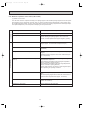
PERFORMANCE DATA
HEAT operation
MSZ-G09SV - E1 MUZ-G09SV - E1
CAPACITY:3.6(KW)
INDOOR
DB(;)
15
21
26
INPUT:1140(W)
OUTDOOR DB(;)
-10
-5
0
5
10
15
20
Q INPUT Q INPUT Q INPUT Q INPUT Q INPUT Q INPUT Q INPUT
2.27 741 2.74 889 3.20 1003 3.67 1083 4.14 1151 4.57 1186 5.04 1208
2.16 798 2.59 946 3.06 1049 3.49 1129 3.96 1186 4.39 1220 4.84 1265
1.94 855 2.41 1003 2.84 1106 3.31 1186 3.78 1243 4.21 1277 4.68 1311
MSZ-G12SV - E1 MUZ-G12SV - E1
CAPACITY:4.8(KW)
INDOOR
DB(;)
15
21
26
INPUT:1540(W)
OUTDOOR DB(;)
-10
-5
0
5
10
15
20
Q INPUT Q INPUT Q INPUT Q INPUT Q INPUT Q INPUT Q INPUT
3.02 1001 3.65 1201 4.27 1355 4.90 1463 5.52 1555 6.10 1602 6.72 1632
2.88 1078 3.46 1278 4.08 1417 4.66 1525 5.28 1602 5.86 1648 6.46 1709
2.59 1155 3.22 1355 3.79 1494 4.42 1602 5.04 1679 5.62 1725 6.24 1771
NOTE
Q :Total capacity (kW)
INPUT :Total power input (W)
23
OB245-1.qxp
8
3/3/00 11:24 AM
Page 24
MICROPROCESSOR CONTROL
MSZ-G09SV- E1
MSZ-G12SV- E1
WIRELESS REMOTE CONTROLLER
Signal transmitting section
Once the operation mode are set, the same operation mode can
be repeated by simply turning the OPERATE/STOP(ON/OFF)
button ON.
Indoor unit receives the signal with a beep tone.
When the system turns off, 3-minute time delay will operate to
protect system from overload and compressor will not restart for
3 minutes.
8-1. “I FEEL CONTROL” (
Operation display section
AM
PM
CLOCK
6 00 1 1 00
OPERATE /STOP
(ON /OFF)button
ON/OFF
TOO
WARM
TOO
COOL
OPERATION SELECT button
) OPERATION
1. Press OPERATE/STOP(ON/OFF) button on the remote
controller. OPERATION INDICATOR lamp of the indoor
unit will turn on with a beep tone.
2. Select “I FEEL CONTROL”(
) mode with the OPERATION SELECT button.
3. The operation mode is determined by the room temperature at start-up of the operation.
TEMPERATURE buttons
MODE I FEEL COOL DRY HEAT
FAN
VANE
ECONO COOL
SWING
START
STOP
VANE CONTROL button
FAN SPEED CONTROL button
ECONO COOL button
Initial room temperature
Mode
25: or more
COOL mode of
"I FEEL CONTROL"
23: to 25:
DRY mode of
"I FEEL CONTROL"
less than 23:
HEAT mode of
"I FEEL CONTROL"
SWING button
ON-TIMER button
CLOCK SET button
OFF-TIMER button
HR. CLOCK MIN.
HR. button
MIN. button
(TIME SET button)
RESET button
RESET
● Once the mode is fixed, the mode does not change by
room temperature afterwards.
INDOOR UNIT DISPLAY SECTION
● Under the ON-TIMER (
) operation, mode is determined according to the room temperature at set time the
operation starts.
● When the system is stopped on the remote controller, and
Operation Indicator lamp
The operation indicator at the right side of the indoor unit
indicates the operation state.
restarted within 2 hours in “I FEEL CONTROL” (
)
mode, the system operates in previous mode automatically regardless of the room temperature.
lighting
Operation
Indicator
Indication
not lighting
Operation state
This shows that the
air conditioner is
operating to reach
the target temperature.
Please wait until the
target temperature is
obtained.
This shows that the
room temperature is
approaching the
target temperature.
Difference
betweeen set
temperature
and room
temperature
Example
Previous operation
COOL mode of
“I FEEL CONTROL” or
COOL mode
Restart
COOL mode of “I
FEEL CONTROL”
Approx. 2 :
or more
When the system is restarted after 2 hours and more, the
operation mode is determined by the room temperature
at start-up of the operation.
Restart
Approx. 2 :
or less
Example
Previous operation
COOL mode of “I FEEL
CONTROL” or COOL
mode
24
COOL or DRY or
HEAT mode of “I
FEEL CONTROL”
that determined
by room temperature at start-up of
the operation.
OB245-1.qxp
3/3/00 11:24 AM
Page 25
4. The initial set temperature is decided by the initial room temperature.
Model
Initial room temperature
COOL mode of
"I FEEL CONTROL"
26: or more
Initial set temperature
24:
❈1
26: to 26:
Initial room temperature minus 2:
DRY mode of
"I FEEL CONTROL"
23: to 25:
Initial room temperature minus 2:
HEAT mode of
"I FEEL CONTROL"
less than 23:
26:
❈1 When the system is restarted with the remote controller, the system operates with the previous set temperature regardless of the room temperature at restart.
The set temperature is calculated by the previous set temperature.
5. TEMPERATURE buttons
In “I FEEL CONTROL” (h)mode, set temperature is decided by the microprocessor based on the room temperature.
In addition, set temperature can be controlled by TOO WARM or TOO COOL buttons when you feel too cool or too warm.
Each time the TOO WARM or TOO COOL button is speed, the indoor unit receives the signal emits a beep tone.
● Fuzzy control
When the TOO COOL or TOO WARM button is pressed, the microprocessor changes the set temperature, considering the room temperature, the frequency of pressing TOO COOL or TOO WARM button and the user’s preference to
heat or cool. So this is called “Fuzzy control”, and works only in “I FEEL CONTROL” mode.
In DRY mode of “I FEEL CONTROL”, the set temperature doesn’t change.
▼ TOO
COOL … To raise the set temperature 1 ~ 2 degrees (:)
▲ TOO
WARM … To lower the set temperature 1 ~ 2 degrees (:)
— Cool mode of “I FEEL CONTROL” —
1. Indoor fan speed control
Indoor fan operates continuously at the set speed by FAN SPEED CONTROL button
regardless of the thermostat’s OFF-ON.
In AUTO the fan speed is as follows.
Initial temperature difference
Fan speed
Difference between room
temperature and set temperature during operation.
Room temperature minus set temperature: 2 degrees or moreover································· Hi
Room temperature minus set temperature: Between 1 and 2 degrees ··························· Me
2 deg. 4 deg.
Room temperature minus set temperature: less than 1 degree········································ Lo
1 deg. 1.7 deg.
2. Coil frost prevention
1 Temperature control
The operational frequency of the compressor is controlled based on the temperature of the indoor coil thermistor(RT12).
Temperature of indoor coil thermistor:RT12
Operation frequency
approx. 8°C or above
normal
approx. 6°C to 8°C
fixed
approx. 3°C to 6°C
lower at the rate of 3Hz/min.
approx. 3°C or below
lower at the rate of 6Hz/min
Compressor is turned OFF for 5 minutes when left temperature
continues for 5 minutes or more.
• The indoor fan maintains the actual speed of the moment.
2 Time control
When the three conditions as follows have been satisfied for 1 hour and 45 minutes, compressor stops for 3 minutes.
The indoor fan operates at set speed.
a. Compressor has been continuously operating.
b. Indoor fan speed is Lo or Me
c. Room temperature is below 26:.
When compressor stops, the accumulated time is cancelled. When compressor restarts, time counting starts from the
beginning.
Time counting also stops temporarily when the indoor fan speed becomes Hi or the room temperature exceeds 26:.
However, when two of the above conditions(b and c.) are satisfied again. Time accumulation is resumed.
25
OB245-1.qxp
3/3/00 11:24 AM
Page 26
—DRY mode of “I FEEL CONTROL”—
The system for dry operation uses the same refrigerant circuit as the cooling circuit.
The compressor and the indoor fan are controlled by the room temperature.
By such controls, indoor flow amounts will be reduced in order to lower humidity without much room temperature decrease.
1. The operation of the compressor and indoor fan/ outdoor fan
Compressor operates by temperature control and time control.
1 Set temperature is controlled to fall 2°C as initial set temperature.
2 Indoor fan and outdoor fan operate in the same cycle as the compressor.
3 Operational frequency control of compressor is fixed 30Hz.
NOTE ● Coil frost prevention during DRY mode of “I FEEL CONTROL”
The operation is same as coil frost prevention during COOL mode of “I FEEL CONTROL” .
3. Coil frost prevention
The operational frequency of the compressor is controlled based on the temperature of the indoor coil thermistor (RT12).
Temperature of indoor coil thermistor:RT12
Operation frequency
approx. 8°C or above
normal
approx. 6°C to 8°C
fixed
approx. 3°C to 6°C
lower at the rate of 3Hz/min.
approx. 3°C or below
lower at the rate of 6Hz/min.
Compressor is turned OFF for 5 minutes when left temperature continues for 5 minutes or more.
The indoor fan maintains the actual speed of the moment. However, it changes to Lo speed when the compressor stops.
— HEAT mode of “I FEEL CONTROL” —
1. Indoor fan speed control
(1) Indoor fan operates at the set speed by FAN SPEED CONTROL button.
In Auto the fan speed is as follows.
Fan speed
Initial temperature difference
Set temperature minus room temperature: 2 degrees or more············································ Hi
Set temperature minus room temperature: Between 1 and 2 degrees ···························· Me
Set temperature minus room temperature: less than 1 degree················································· Lo
Difference between room
temperature and set temperature during operation
2 deg. 4 deg.
1 deg. 1.7 deg.
(2) Cold air prevention control
1 When the compressor is not operating,
(1) if the temperature of indoor coil thermistor RT12 is 18°C or less, the fan stops.
(2) if the temperature of indoor coil thermistor RT12 is more than 18°C, the fan operates at VLo.
2 When the compressor is operating,
(1) if the temperature of RT12 is 22°C or more, the fan operates at set speed.
(2) if the temperature of RT12 is less than 22°C and
(1) if the temperature of room temperature thermistor RT11 is 15°C or less, the fan stops.
(2) if the temperature of room temperature thermistor RT11 is more than 15°C, the fan operates at VLo.
Indoor coil thermistor
RT12 temperature
Released
Cold Air Prevention
RT12
Fan speed
Set speed
VLo or stop
18: 22:
NOTE : If the temperature of RT12 reads from 18: to 22: at the air conditioner starting and also after defrosting, this
control works.
26
OB245-1.qxp
3/3/00 11:24 AM
Page 27
(3) Warm air control.
When the following any condition of 1(a. ~ d.) and the condition of 2 are satisfied at the same time, warm air control
works.
1 a.) when the operation mode has been changed to HEAT mode
b.) when cold air prevention has been released
c.) when defrosting has been finished
d.) when the compressor starts in HEAT mode
2 When the temperature of indoor coil thermistor RT12 is less than 37°C.
When warm air control works, the fan speed changes as follows to blow out warm air gradually.
Gradation of fan speed in initial
<Time condition>
<Indoor fan speed>
less than 2 minutes
2 minutes to 4 minutes
more than 4 minutes
Lo
Me
Hi
The upper limit of the fan speed in MANUAL is the set speed.
The upper limit of the fan speed in AUTO is the speed decided by indoor fan speed control.
When the temperature of RT12 has been 37°C or more, or when the set speed has been changed, this control is
released and the fan speed is the set speed.
(4) Flow soft control
When the thermostat (compressor) is off, the indoor fan operates as follows.
Compressor
OFF
ON
Fan
VLo
Set speed
NOTE : When the thermostat(compressor) turns on, the fan will operate
at set speed. But until cold air prevention and warm air control
is released, the fan speed follow them.
2. High pressure protection
In HEAT mode and manually-operated HEAT mode, the indoor coil thermistor detects the temperature at the indoor heat
exchanger and controls the compressor rotational frequency to prevent the condensing pressure from increasing excessively.
3. Overload starting
When the room temperature thermistor reads 18°C or above, the compressor runs with its maximum frequency regulated for
3 minutes after the start-up.
4. Defrosting
(1) Starting conditions of defrosting
a) The defrost thermistor attached to the outdoor heat exchanger read -3°C or below.
b) The cumulative operation time of the compressor has reached any of the set values: 35, 40, 45, 50, 55, 60, 65, 70,
75, 80, 85, 90, 95, 100, 105 minutes.
c) More than 5 minutes have passed since the start-up of the compressor.
When the above three conditions, a), b), and c), are satisfied, the defrosting starts.
w Set value of compressor operation time(hereinafter referred to as defrost interval)
The first defrost interval is 32 minutes long, and the second 35 minutes long.The third and subsequent intervals are
set to be longer, and less frequent, depending on defrosting time.
The third and subsequent defrost intervals follow any of the three patterns …5 or 10 minutes longer, the same, or 5 or
10 minutes shorter compared with the previous defrost interval … with the longest 115 minutes and the shortest 30
minutes.
(2) Releasing conditions of defrosting
Defrosting is released when any of the following condition is satisfied:
a) The defrost thermistor reads 13°C or above.
b) Defrosting time has exceeded 10 minutes.
c) Some other mode than HEAT mode is set during defrosting.
27
OB245-1.qxp
3/3/00 11:24 AM
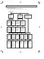
Page 28
Time chart of defrost in HEAT mode (reverse type)
horizontal
Vertical vane
normal
normal
Indoor fan
VLo (temperature of indoor coil thermistor > 18:)
STOP
normal
30
seconds
<outdoor unit>
105Hz (MSZ-G09SV)
125Hz (MSZ-G12SV)
MAX Hz
MAX Hz
Compressor normal
1
30
second seconds
30
seconds
5 seconds
1
second
5
seconds
Outdoor fan motor
normal
normal
OFF
R.V. coil
(21S4)
8-2. COOL (
ON
ON
OFF
) OPERATION
(1) Press OPERATE/STOP(ON/OFF) button. OPERATION INDICATOR lamp of the indoor unit turns on with a beep tone.
(2) Select COOL mode with the OPERATION SELECT button.
(3) Press TEMPERATURE buttons (TOO WARM or TOO COOL button)to select the desired temperature.
The setting range is 16 ~ 31°C
✻ Indoor fan continues to operate regardless of thermostat’s OFF-ON
✻ Coil frost prevention is same as COOL mode of “I FEEL CONTROL”
) OPERATION
(1) Press OPERATE/STOP(ON/OFF) button.
OPERATION INDICATOR lamp of the indoor unit turns on with a
beep tone.
(2) Select DRY mode with the OPERATION SELECT button.
(3) The microprocessor reads the room temperature and determines
the set temperature. Set temperature is as shown on the right
chart.
(4) DRY operation will not function when the room temperature is
13°C or below.
(5) In DRY operation the fan speed Hi or Me notch is lower than that
in COOL operation, but the fan speed Lo notch is same in DRY
and COOL operation.
30
Set temperature
8-3. DRY (
Set temperature and
: initial room temperature in dry mode
35
25
20
15
10
10
28
15
20
25
30
Initial room temperature
35 :
OB245-1.qxp
3/3/00 11:24 AM
8-4. HEAT (
Page 29
) OPERATION
(1) Press OPERATE/STOP(ON/OFF) button.
OPERATION INDICATOR lamp of the indoor unit turns on with a beep tone.
(2) Select HEAT mode with the OPERATION SELECT button.
(3) Press TEMPERATURE buttons (TOO WARM or TOO COOL button) to select the desired temperature.
The setting range is 16 ~ 31°C.
(4) Indoor fan speed control, high pressure protection, defrosting, 4-way valve control are the same as HEAT mode of “I
FEEL CONTROL”
8-5. FAN MOTOR CONTROL
1. Rotational frequency feedback control
The indoor fan motor is equipped with a rotational frequency sensor, and outputs signal to the microprocessor to feedback the rotational frequency. Comparing the current rotational frequency with the target rotational frequency (Hi,Me,Lo)
the microprocessor controls SR141 and adjusts fan motor electric current to make the current rotational frequency close
to the target rotational frequency. With this control, when the fan speed is switched, the rotational frequency changes
smoothly.
2. Fan motor lock-up protection
When the rotational frequency feedback signal is not output for 12 seconds, (or when the microprocessor cannot detect
the signal for 12 seconds) the fan motor is regarded locked-up. Then the electric current to the fan motor is shut off. 3
minutes later, the electric current is applied to the fan motor again. During the fan motor lock-up, the OPERATION INDICATOR lamp flashes on and off to show the fan motor abnormality. (See page 42.)
8-6. AUTO VANE OPERATION
(1) Vane motor drive
These models are equipped with a stepping motor for the horizontal vane. The rotating direction, speed, and angle of
the motor are controlled by pulse signals (approx. 12V) transmitted from indoor microprocessor.
VANE
(2) The horizontal vane angle and mode changes as follows by pressing the VANE CONTROL (
) button.
(3) Positioning
The vane is once pressed to the vane stopper below to confirm the standard position and then set to the desired angle.
Confirming of standard position is performed in case of follows.
(a) When the OPERATE/STOP(ON/OFF) button is pressed.
(b) When the vane control is changed AUTO to MANUAL.
(c) When the SWING is finished.
(d) When the test run starts.
(e) When the power supply turns ON.
(4) VANE AUTO (
) mode
In VANE AUTO mode, the microprocessor automatically determines the vane angle and operation to make the optimum
room-temperature distribution.
(1) In COOL and DRY operation
Vane angle is fixed to Angle 1.
Vane angle is fixed to Angle 4.
(2) In HEAT operation
29
OB245-1.qxp
3/3/00 11:24 AM
Page 30
(5) Dew prevention
During COOL or DRY operation with the vane angle at Angle 4 or 5 when the compressor cumulative operation time
exceeds 1 hour, the vane angle automatically changes to Angle 1 for dew prevention.
(6) SWING MODE (
)
SWING
By pressing the SWING button (
),vane swings horizontally. The remote controller displays “
SWING MODE is cancelled when any of the following operations are performed.
● The unit is turned off.
The vertical vane will return to their positions just before the swing operation was started.
● The operation mode(AUTO, COOL, DRY or HEAT)is changed.
The vertical vane will return to their positions just before the swing operation was started.
”.
SWING
●
The SWING button (
) is pressed.
The vertical vane stop at the position when the button is pressed.
(7) Horizontal AIR FLOW (
)
SWING
The auto vane angle changes as follows by pressing the SWING button (
).
SWING
●
Press the SWING button (
).
The vertical vane begin moving.
●
When the vane move to the desired position, press the SWING button (
The vane stop moving.
SWING
)again.
NOTE
SWING
If the SWING button (
) is not pressed again within 30 seconds in COOL or DRY mode or within 1 minute in HEAT
mode after the vane start moving, the vane will automatically return to their original positions.
Horizontal AIR FLOW blowing range
About 100COOL and DRY
About 150HEAT
(8) Cold air prevention in HEAT mode.
When any of the following conditions occurs in HEAT mode, the auto vane angle changes to Angle 1 automatically to
prevent cold air blowing on users.
① Compressor is not operating.
➁ Defrosting is performed.
➂ Indoor coil thermistor RT12 reads 24: or below.
➃ Indoor coil thermistor RT12 temperature is raising from 24°C or below, but it does not exceed 28:.
30
OB245-2.qxp
3/3/00 11:25 AM
Page 31
(8) ECONO COOL (
) operation (ECONOmical operation)
When the ECONO COOL button is pressed in COOL mode, set temperature is automatically set 2°C higher than that
in COOL mode.
Also the horizontal vane swings in various cycle according to the temperature of indoor heat exchanger(RT12).
SWING operation makes you feel cooler than set temperature. So, even though the set temperature is higher than that
in COOL mode, the air conditioner can keep comfort. As a result, energy can be saved.
NOTE : ECONO COOL operation not work in COOL mode of “I FEEL CONTROL”.
SWING operation
In swing operation of ECONO COOL operation air flow is initially blew out upward(levelly).
According to the temperature of indoor coil thermistor RT12 at starting of this operation, next downward blow time is
decided. Then when the downward blow has been finished, next upward blow time is decided.
For initial 10 min. the swing operation is performed in table G~H for quick cooling(but G : RT 12 is 24: or less).
Also, after 10 min. when the difference of set temperature and room temperature is more than 2 degrees, the swing
operation is performed in table D~H for more cooling(but D: RT12 is 20: or less).
The air conditioner repeats the swing operation in various cycle as follows.
Upward(level) blow time
(sec.)
Temperature of indoor
coil thermistor RT12
Downward blow time
(sec.)
15°C or less
2
23
15°C to 17°C
5
20
D
17°C to 18°C
18°C to 20°C
8
11
17
14
E
20°C to 21°C
14
11
F
G
21°C to 22°C
17
8
22°C to 24°C
H
more than 24°C
20
23
2
A
B
C
5
8-7. TIMER OPERATION
1. How to set the timer
(1) Press OPERATE/STOP(ON/OFF) button to start the air conditioner.
(2) Check that the current time is set correctly.
NOTE : Timer operation will not work without setting the current time. Initially “AM0:00” blinks at the current time display
of TIME MONITOR, so set the current time correctly with CLOCK SET button.
(3) Press ON or OFF TIMER buttons to select the operation.
“
” button... AUTO START operation (ON timer)
“
” button... AUTO STOP operation (OFF timer)
(4) Press HR. and MIN. button to set the timer. Time setting is 10-minute units.
HR. and MIN. button will work when “
” or “
” mark is flashing.
These marks disappear in 1 minute.
After setting the ON timer, check that OPERATION INDICATOR lamp of the indoor unit lights.
NOTE1 : Be sure to place the remote controller at the position where its signal can reach the air conditioner even during
TIMER operation, or the set time may deviate within the range of about 10 minutes.
NOTE2 : Reset the timer in the following cases, or the set time may deviate and other malfunctions may occur.
● A power failure occurs.
● The circuit breaker functions.
2. Cancel
TIMER setting can be cancelled with the ON or OFF TIMER buttons. (“
To cancel the ON timer, press the “
” button.
To cancel the OFF timer, press the “
” button.
TIMER is cancelled and the display of set time disappears.
31
” or “
”)
OB245-2.qxp
3/3/00 11:25 AM
Page 32
PROGRAM TIMER
● The OFF timer and ON timer can be used in combination.
●“
” and “
” display shows the order of the OFF timer and ON timer operation.
(Example 2) The current time is 11:00 AM.
(Example 1) The current time is 8:00 PM.
The unit turns on at 5:00 PM, and off at 9:00 PM.
The unit turns off at 11:00 PM, and on at 6:00 AM.
NOTE : TIMER setting will be cancelled by power failure or breaker functioning.
8-8. EMERGENCY-TEST OPERATION
When the remote controller is missing, has failed or the batteries run down, use the EMERGENCY OPERATION switch on
the front of the indoor unit. The unit will start and the OPERATION INDICATOR lamp will light.
The first 30 minutes of operation is the test run operation. This operation is for servicing. The indoor fan speed runs at Hi
notch and the system is in continuous operation. (The thermostat is ON)
After 30 minutes of test run operation the system shifts to EMERGENCY COOL, HEAT MODE with a set temperature of
24°C.
The fan speed shifts to Me notch.
This operation continues until the EMERGENCY OPERATION switch button is pressed once or twice or the unit receives
any signal from the remote controller. In case of latter normal operation will start.
The coil frost prevention works even in this operation, and defrosting too.
In the test run or emergency operation, the horizontal vane operates in VANE AUTO mode.
NOTE : Do not press the EMERGENCY OPERATION switch during normal operation.
OPERATION INDICATOR lamp
Press once <Cool>
EMERGENCY
OPERATION switch
Press again <Heat>
Press once again <Stop>
lighting
not lighting
32
OB245-2.qxp
3/3/00 11:25 AM
Page 33
8-9. Operational frequency control of outdoor unit
1. Outline
The operational frequency is decided by following:
First, set the target operational frequency based on the difference between the room temperature and the set temperature.
Second, regulate the target operational frequency by discharge temperature protection, high pressure protection, electric
current protection and overload protection and also by the maximum/minimum frequency.
(1) Maximum/minimum frequency in each operation mode.
HEAT
COOL
Applied
model
minimum
frequency
rating
frequency
minimum
frequency
maximum
frequency
rating
frequency
maximum
frequency
DRY
MSZ-G09SV-
E1
45
79
92
45
95
105
45
MSZ-G12SV-
E1
15
85
105
15
96
125
30
w The maximum frequency in COOL mode varies according to operation hours, as shown below.
w However, it is under 79Hz(MSZ-G09SV)/ 85Hz(MSZ-G12SV) when indoor fan speed set to MANUAL Lo or AUTO Lo.
Maximum
frequency
Frequency
Rating or under-rating frequency
1Hr
Time: T
(2) Frequency change speed
During increasing frequency
Operational frequency
MUZ-G09SV-
E1
MUZ-G12SV-
10Hz~14Hz
0.5 sec./Hz
15Hz~79Hz
10 sec./Hz
80Hz~150Hz
0.5 sec./Hz
E1
During decreasing frequency
Operational frequency
MUZ-G09SV-
E1
MUZ-G12SV-
10Hz~42Hz
1 sec./Hz
43Hz~150Hz
0.5 sec./Hz
33
E1
OB245-2.qxp
3/3/00 11:25 AM
Page 34
8-10. Electronic expansion valve control (LEV control)
(1) Outline of LEV control
general operation
standard
specification
The LEV basic control is comprised of setting LEV opening degree to the standard opening degrees set for each operational frequency of the compressor. However, when any change in indoor/outdoor temperatures or other factors cause
air conditioning load fluctuation, the LEV control also works to correct LEV opening degree based on discharge temperature (Shell temperature) of the compressor, developing the unit’s performance.
Control range
from min. 33 pulse to max. 350 pulse.
Actuating speed
LEV opens 40 pulse/sec. and close 90 pulse/sec.
Opening degree adjustment
LEV opening degree is always adjusted in opening direction.
(When reducing the opening degree, LEV is once overclosed, and then adjusted to the proper degree by opening.
Unit OFF
LEV remains at max. opening degree (reaches max. opening
degree approx. 15 minutes after compressor stops)
Remote controller ON
LEV is positioned. (first full-closed at zero pulse and then
positioned.)
During 2 to 13 minutes after compressor starts
Opening degree is adjusted according to standard opening
degree.
(Standard opening degree is set for each rotational frequency of compressor)
More than 13 minutes have passed since compressor
start-up
LEV opening degree is corrected to get target discharge
temperature of compressor.
(For discharge temperature lower than target temperature,
LEV is corrected in closing direction.)
(For discharge temperature higher than target temperature,
LEV is corrected in opening direction.)
wIt may take more than 30 minutes to reach target temperature, depending on operating conditions.
Thermostat OFF
LEV starts to open every 3 pulse/sec.
from
the same opening degree as that when the Unit turned OFF
(and becomes full-opened after approx. 15 minutes.)
Thermostat ON
LEV is controlled in the same way as that is after the compressor has started up.
Defrosting in HEAT mode
LEV is adjusted to open 350 pulse.
34
3/3/00 11:25 AM
Page 35
(2) Time chart
Air conditioner ON
Air conditioner OFF
(thermostat off)
LEV opening degree
Positioning
Opening degree is
corrected according
to discharge
temperature.
Standard
opening
degree
Commanded
to open
Time
13 min.
The operational frequency
of the compressor
ON
OFF Time
(3) Control data
(a) Reference value of target discharge temperature
(Cooling :/ Heating :)
A
B
C
D
E
F
MSZ-G09SV-
E1
58/49
63/58
69/66
74/71
74/76
74/78
MSZ-G12SV-
E1
57/48
60/57
67/66
75/71
78/76
78/78
LEV opening degree
OB245-2.qxp
06
05
04
03
02
01
F
E
D
C
B
A(target discharge temperature)
30
50
70
90
110
130 (Hz)
The operational frequency of the compressor
In COOL mode, the two indoor coil thermistor (one main and one sub) sense temperature ununiformity (super heat)
at the heat exchanger, And when temperature difference have developed, the indoor coil thermistors adjust LEV
opening to get approximate 10 degrees lower temperature than the target temperature in the table above, thus
diminishing super heat.
(b) Reference value of LEV standard degree opening
(COOL/ HEAT pulse)
01
02
03
04
05
06
MSZ-G09SV-
E1
150/70
MSZ-G12SV-
E1
160/90 190/120 200/140 220/160 240/180 255/200
170/90 180/110 190/140 200/150 200/160
35
OB245-2.qxp
3/3/00 11:25 AM
Page 36
8-11. Outdoor fan motor control
The AC fan motor turns ON/OFF, interlocking with the compressor.
[ON]
The AC fan motor turns on 5 seconds before the compressor starts up.
[OFF]
The AC fan motor turns off 15 seconds after the compressor stops running.
ON
5 sec.
15 sec.
Compressor
OFF
ON
Outdoor fan
OFF
8-12. 4-way valve control
COOL&DRY mode . . . . . . . OFF(Voltage is not supplied from relay P.C. board to R.V. Coil.)
. . . . . . . . . . . . . . . . . . . . . . During normal COOL operation the 4-way valve is OFF.
HEAT mode . . . . . . . . . . . . ON(Voltage is supplied from relay P.C. board to R.V. Coil.)
. . . . . . . . . . . . . . . . . . . . . . The 4-way valve is ON as soon as thermostat turns ON.
. . . . . . . . . . . . . . . . . . . . . . The 4-way valve is OFF 15 minutes after the thermostat turns OFF.
w The 4-way valve isn’t ON before the compressor starts up.
<COOL>
<HEAT>
5 seconds
Compressor
ON
OFF
4-way valve
ON
OFF
Outdoor fan
ON
OFF
5 seconds
36
OB245-2.qxp
3/3/00 11:25 AM
Page 37
8-13. Indoor fan motor control
The detected rotational frequency of the fan motor is feed backed to the microprocessor and then the microprocessor
works to keep the rotational frequency at a fixed value against load fluctuation.
(1) Circuit block diagram
Solid state
relay output
every 100Hz pulse output
AC motor
AC motor
actuator
(Solid state relay)
Microprocessor
230V AC
Rotational frequency
rotational
frequency
sensor
part
Controller board
output
input
(2) Control system
<Output side>
The microprocessor outputs pulse
every 100Hz (every 50Hz in half wave).
(Fan speed varies according to the
time span between a Zero-cross point
on the commercial wave and a pulse
out put point.)
The microprocessor drives solid
state relay on
relay P.C. board.
Controlled voltage
is applied to AC
fan motor.
<Input side>
The microprocessor detects rotational
frequency of AC fan motor, using Hall
element in AC fan motor.
The microprocessor adjusts rotational frequency.
If feed backed pulses are not detected for 12
seconds, fan motor becomes abnormal and
indoor OPERATION INDICATOR lamp flashes
to show abnormality.
37
OB245-2.qxp
3/3/00 11:25 AM
9
Page 38
SERVICE FUNCTIONS
MSZ-G09SV - A1
MSZ-G12SV - A1
9-1. CHANGE IN DEFROST SETTING
<JS> When the JS wire of the outdoor electronic control P.C. board is cut, the defrost temperature will be changed.
(Refer to page 55.)
Jumper wire
JS
Change point
Deforst finish temperature changes from 13: to 15:.
9-2. TIMER SHORT MODE
For service, set time can be shortened by short circuit of JPS on and the electronic control P.C. board.
The time will be shortened as follows.
3-minute delay : 3-minute ➔ 3-second.
AUTO START : 1 hour ➔ 1-minute
Short the connector during the timer mode.
AUTO STOP : 1 hour ➔ 1-minute
}
9-3. P.C. BOARD MODIFICATION FOR INDIVIDUAL OPERATION
A maximum of 4 indoor units with wireless remote controllers can be used in a room. In this case, to operate each indoor
unit individually by each remote controller, P.C. boards of remote controller must be modified according to the indoor unit
number.
How to modify the remote controller P.C. board
Remove batteries before modification.
The board has a print as shown below;
NOTE : For remodelling, take out the batteries at first.
After finish remodelling, put back the batteries then push the RESET-button.
The P.C. board has the print “J1” and “J2”. Jumper wires are mounted to each “J1” and “J2”.Cut “J1” and “J2” according
to the number of indoor unit as shown in Table 1.
After modification, push the RESET. button near the MIN-button on the remote controller.
Table1.
No.1
No.2
No.3
No.4
unit
unit
unit
unit
1 unit operation
No modification
2 unit operation
Same as at left
Cut J1
3 unit operation
Same as at left
Same as at left
Cut J2
4 unit operation
Same as at left
Same as at left
Same as at left
Cut both J1 and J2
NOTE : At power supply failure or installation, indoor unit deletes the memory about remote controller. When
the power supply is turned on and indoor unit receives the first signals from the remote controller, the
remote controller number is designated as the indoor unit number. Therefore at and after the second
time indoor unit accepts the remote controller of the initial setting number.
At setting - error, turn the power supply off to cancel the individual operation and then turn the power
supply on to restart the setting.
38
OB245-2.qxp
3/3/00 11:25 AM
Page 39
9-4. AUTO RESTART FUNCTION
When the indoor unit is controlled with the remote controller, the operation mode, the set temperature, and the fan speed
are memorized by the indoor electronic control P.C.board. The “AUTO RESTART FUNCTION” sets to work the moment
the power has restored after power failure. Then, the unit will restart automatically. However if the unit is operated in “I
FEEL CONTROL.” mode before power failure, the operation is not memorized. In “I FEEL CONTROL.” mode, the operation is decided by the initial room temperature.
How to set “AUTO RESTART FUNCTION”
1Turn off the main power for the unit.
2Pull out the indoor electronic control P.C. board and the display P.C.board.(See page 58.)
3Cut the RESISTOR JR07 on the indoor electronic control P.C. board.
C11
CN
21
1
CN201
CN121
SW
IC101
CN112
CN111
52C
CN151
JR07
Operation
1If the main power (230V AC) has been cut, the operation settings remain.
2After the power is restored, the unit restarts automatically according to the memory.(However, it takes at least 3 minutes
for the compressor to start running.)
NOTE:
•The operation settings are memorized when 10 seconds have passed after the indoor unit was operated with the remote
controller.
•If the main power is turned off or a power failure occurs while AUTO START/STOP timer is active, the timer setting is
cancelled.
•If the unit has been off with the remote controller before power failure, the auto restart function does not work as the
power button of the remote controller is off.
•To prevent breaker off due to the rush of starting current, systematize other home appliances not to turn on at the same
time.
•When some air conditioners are connected to the same supply system, if they are operated before power failure, the
starting current of all the compressors may flow simultaneously at restart.
Therefore, the special counter-measures are required to prevent the main voltage-drop or the rush of the starting current
by adding to the system that allows the units to start one by one.
39
OB245-2.qxp
10
3/3/00 11:25 AM
Page 40
TROUBLESHOOTING
MSZ-G09SV - E1
MSZ-G12SV - E1
11-1. Cautions on troubleshooting
1. Before troubleshooting, check the following:
1) Check the power supply voltage.
2) Check the indoor/outdoor connecting wire for mis-wiring.
2. Take care the following during servicing.
1) Before servicing the air conditioner, be sure to first turn off the remote controller to stop the unit, and then after confirming the horizontal vane is closed, turn off the breaker and / or disconnect the power plug.
2) Be sure to unplug the power cord before removing the front panel, the cabinet, the top panel, and the electronic control P.C. board.
3) When removing the electronic control P.C. board, hold the edge of the board with care NOT to apply stress on the
components.
4) When connecting or disconnecting the connectors, hold the housing of the connector. DO NOT pull the lead wires.
3. Troubleshooting procedure
1) First, check if the OPERATION INDICATOR lamp on the indoor unit is flashing on and off to indicate an abnormality.
To make sure, check how many times the abnormality indication is flashing on and off before starting service work.
2) Before servicing check that the connector and terminal are connected properly.
3) If the electronic control P.C. board is supposed to be defective, check the copper foil pattern for disconnection and the
components for bursting and discoloration.
4) When troubleshooting, refer to the flow chart on page 41 and the check table on page 42 and 43.
4. How to replace batteries
Weak batteries may cause the remote controller malfunction.
In this case, the remote controller can not be repaired only by the battery replacement. To operate the remote controller
normally, replace the batteries in the following order.
This remote controller has the RESET button. After refilling new batteries, press the RESET button with tip end of ball
point pen or the like, and then use the remote controller.
40
OB245-2.qxp
3/3/00 11:26 AM
Page 41
10-2. Troubleshooting procedure
The following procedure facilitates identifying defective points.
Details of OPERATION INDICATOR lamp flashing can be located on page 42 and 43.
Start
Indoor unit
operates.
Outdoor unit
doesn't
operate.
Indoor unit
does'nt receive
the signal from
remote controller.
OPERATION INDICATOR
lamp on the indoor unit is
flashing on and off.
Outdoor unit
operates in
only Test Run
operation.
Outdoor unit
does'nt
operate
even in
Test Run
operation.
Indoor unit
operates, when
the EMERGENCY
OPERATION
switch is pressed.
Indoor unit
doesn't operate,
when the
EMERGENCY
OPERATION
switch is pressed.
Check room
temperature
thermistor.
Refer to
"Test point
diagram and
voltage" on
page 54.
Refr to A
"How to check
inverter/
compressor"
on page 47.
Refer to H
"Check of
remote controller
and receiver
P.C. board"
on page 49.
Refer to I
"Check of indoor
electronic control
P.C. board"
on page 50.
2-time flash
3-time flash
1-time flash
Cause:
Cause:
Cause: Indoor/
Indoor unit
Indoor unit
Outdoor unit
• Trouble of
• Trouble of
• Mis-wiring
room temperindoor fan
• Serial signal
ature/
indoor
motor
error
coil thermistor
Refer to 10-2.2
"Checking
mis-wiring and
serial signal
errer"
on page 44.
Check room
temperature
thermistor and
indoor coil
thermistor.
Refer to
"Test point
diagram and
voltage"
on page 54.
Refer to G
"Check of
indoor fan
motor"
on page 49.
5-time flash
Cause:
Outdoor unit
• Outdoor
power
system
abnormality
6-time flash
Cause:
Outdoor unit
• Trouble of
thermistor
in outdoor
unit
Refer to A
"How to check
inverter/
compressor"
on page 47.
Refer to J
"Check of
outdoor
thermistors"
on page 50.
41
7-time flash
Cause:
Outdoor unit
• Trouble of
outdoor
control
system
Replace the
outdoor
electronic
control
P.C. board.
OB245-2.qxp
3/3/00 11:26 AM
Page 42
1. Troubleshooting check table
MSZ-G09SV - E1
MSZ-G12SV - E1
(Indoor unit troubleshooting check table)
flashing
Operation
Indicator
· Flashing of the operation indicator lamp (on the left-hand side) indicates possible abnormalities.
· The operation indicator lamp (on the left-hand side) is lighting during normal operation.
No.
Symptom
Outdoor unit
does not
operate
Detection method
Checkpoint
repeated flashes
every 0.5 seconds
Operation indicator lamp
Mis-Wiring
Abnormal point
When indoor electronic control P.C. board does not
receive serial signals for 4 to 5 seconds with
OPERATION/ STOP(ON/ OFF) button of remote
controller ON and 52C relay ON for the first time.
NOTE: In case of serial signal error, mis-wiring
indication will appear by turning power off
and then turning it back on.
Refer to 'Checking
serial signal error' on
page 44.
1-time flash
2.5 seconds OFF
Serial signal
When indoor electronic control P.C. board does not
receive serial signals from outdoor unit for 4 to 5
seconds,
2-time flash
2.5 seconds OFF
Indoor coil
thermistor
Auxiliary indoor
coil thermistor
Room
temperature
thermistor
Indoor electronic control P.C. board constantly
detects resistance every 8 seconds.
When thermistor shorts or opens.
3-time flash
2.5 seconds OFF
Indoor fan motor
5-time flash
2.5 seconds OFF
6-time flash
2.5 seconds OFF
1
w2
w3
w4
5
When rotational frequency feedback signal is not
emit during 12-second indoor fan operation.
Refer to G "Check of
indoor fan motor" on
page 49.
Outdoor power
system
When compressor has stopped due to over current
protection or start-up failure protection 3 times in a
row within 1 minute after start-up.
Refer to A "How to
check inverter/
compressor" on page
47.
Outdoor
thermistors
<Thermistor short>
Thermistors are abnormal when they short after
compressor start-up.
<Thermistor open>
Thermistors are abnormal when they open after
compressor start-up.
However, discharge temperature thermistor is
abnormal when open circuit is detected more than
10 minutes after compressor start-up.
· Shortage of
refrigerant
· Outdoor electronic
control P.C. board
When nonvolatile memory data cannot be read properly
on outdoor control P.C. board, outdoor unit stops and
restarts 3 minutes later.
Replace outdoor
electronic control P.C.
board.
6
7
7-time flash
2.5 seconds OFF
Refer to the
characteristics of
indoor coil thermistor,
auxiliary indoor coil
thermistor, and room
temperature thermistor
on page 54.
Outdoor control
system
Refer to J "Check
of outdoor
thermistors" on
page 50.
w When the indoor unit has started operation and the above detection method has detected an abnormality (the first detection
after the power ON), the electronic control P.C. board turns OFF the 52C and the indoor fan motor with the operation indicator lamp lighting.
When the 52C and the indoor fan motor are turned ON again 3 minutes later and the same abnormality is detected (a second detection of the above abnormality after the power ON), the control P.C. board turns OFF the 52C and the indoor fan
motor with the operation indicator lamp flashing.
However, the first detection is cleared in case the power is turned OFF after the first detection.
42
OB245-2.qxp
3/3/00 11:26 AM
Page 43
(Outdoor LED indication table)
MUZ-G09SV - E1
MUZ-G12SV - E1
<Outdoor electronic control P.C. board>
LED
NOTE 1. The location of LED is illustrated at the right figure.
2. LED lights up during normal operation.
Transistor
module
Hybrid
IC
flashing
transformer
No.
1
Symptom
Outdoor unit
does not
operate
LED indication
2
NOTE:
For abnormality
location, refer to
'Indoor
troubleshooting
check table' on
page 41.
3
4
5
6
'Outdoor unit
stops and
restarts 3
minutes later'
is repeated
7
Outdoor unit
operates (at
low
frequency)
Checkpoint
· Refer to 'Checking serial signal
error' on page 44.
· Refer to M 'Check of power supply'
on page 52.
Outdoor power
system
When compressor has stopped by over current protection
within 1 minute after compressor start-up 3 times in a row,
compressor stops and then restarts 3 minutes later.
· Refer to A 'How to check inverter/
compressor' on page 47.
Outdoor
thermistors
When discharge temperature thermistor or fin temperature
thermistor shorts or opens during compressor running,
compressor stops and restarts 3 minutes later.
· Refer to J 'Check of outdoor
thermistors' on page 50.
Outdoor control
system
When nonvolatile memory date cannot be read properly,
compressor stops and restarts 3 minutes later.
Replace outdoor electronic control
P.C. board.
Over current
2-time flash
2.5 seconds OFF protection
When 19A(MUZ-G09SV)/ 29A(MUZ-G12SV) current flows into Refer to A 'How to check inverter/
power transistor, compressor stops and restarts 3 minutes later. compressor on page 47.
3-time flash
Discharge
2.5 seconds OFF temperature
overheat
protection
When discharge temperature thermistor exceeds 116:,
compressor stops and restarts 3 minutes later.
(Compressor restarts when discharge temperature thermistor
reads 100: or below.)
· Check refrigerant circuit and
refrigerant amount.
· Refer to J 'Check of outdoor
thermistors' on page 50.
4-time flash
Fin temperature
2.5 seconds OFF thermistor overheat
protection
When temperature at heat sink exceeds 78:(MUZ-G09SV)/
80:(MUZ-G12SV) or outdoor electronic control P.C. board
exceeds 68:(MUZ-G09SV)/ 78:(MUZ-G12SV), compressor
stops and restarts 3 minutes later.
When indoor coil thermistor exceeds 75:, compressor stops
and restarts 3 minutes later.
· Check around outdoor unit.
· Check outdoor unit air passage.
Frequency drop by When current from power outlet exceeds 8A(MUZ-G09SV)/
1-time flash
2-5 seconds OFF current protection 9A(MUZ-G12SV), compressor frequency lowers.
3-time flash
Frequency drop by When indoor coil thermistor exceeds 55: in HEAT mode,
2-5 seconds OFF high pressure
compressor frequency lowers.
protection
10
· Check refrigerant circuit and
refrigerant amount.
· Check stop valve.
The unit is normal, but check the
following.
· Check if indoor filters are clogged
· Check if refrigerant is short.
· Check if indoor/outdoor unit air
outlets are short cycled.
Frequency drop by When indoor coil thermistor reads 8: or below in COOL mode,
defrosting in COOL compressor frequency lowers.
mode
4-time flash
Frequency drop by, When discharge temperature thermistor exceeds 111:,
2-5 seconds OFF discharge
compressor frequency lowers.
temperature
protection.
11
12
Detection method
When serial signal stops from indoor unit for 60 seconds,
compressor stops and then restarts 3 minutes later.
5-time flash
High pressure
2.5 seconds OFF protection
8
9
Abnormal point
1-time flash every Serial signal
2.5 seconds
Outdoor unit
operates
5-time flash
Outdoor
2-5 seconds OFF thermistors.
Defrost thermistor.
When defrost thermistor short or open.
w In this case, compressor continues running.
Refer to J 'Check of outdoor
thermistors' on page 50.
13
6-time flash
Power factor
2-5 seconds OFF detection
When power factor of compressor is not detected.
w In this case, compressor continues running.
Check compressor wiring.
14
7-time flash
Low discharge
2-5 seconds OFF temperature
protection
When discharge temperature has been 50: or below for 20
minutes.
· Refer to P 'Check of LEV' on
page 53.
· Check refrigerant circuit and
refrigerant amount.
The flashing frequency shows the number of times the LED blinks after every 2.5-second OFF.
(Example) When the flashing frequency is “2”.
0.5-second ON
ON
2.5-second OFF
2.5-second OFF
OFF
43
0.5-second ON
OB245-2.qxp
3/3/00 11:26 AM
Page 44
2. Checking mis-wiring and serial signal error
Outdoor unit does not operate. When the OPERATION INDICATOR lamp (on the left-hand side) flashes on and off
continuously or only once.
1. Turn OFF the power supply.
2. Turn ON the power supply.
3. Press the EMERGENCY OPERATION switch.
ON 2.5 seconds OFF ON
Is the self-check function of indoor unit indicated when 52C turns ON
3 minutes later? w1
Short circuit of JPG and JPS on the indoor electronic control P.C. board
enables self-check to be displayed in 3 seconds.
(
)
Serial signal error indication
w1 If there is any error in
serial signal system, the
mis-wiring indication will
appear by turning the
power OFF and then
turning it back.
Mis-wiring indication
Repair wiring.
Yes
Is there indoor-outdoor mis-wiring,
poor contact, or wire disconnection?
No
A
Turn OFF the power supply and confirm that indooroutdoor wiring is correct.
Short-circuit indoor terminal block N and 3.
B While pressing OPERATE-STOP(ON/ OFF) button on
the remote controller, press the RESET button.
(The above procedure allows OPERATION INDICATOR
lamp to indicate the failure-mode.) w2
w2 Mis-wiring may damage indoor the
electronic control P.C. board during the
operation in the left. Be sure to confirm
the wiring is correct before the operation
starts.
flashing
Does the OPERATION INDICATOR lamp flash
on and off when OPERATE/STOP(ON/OFF)
button on the remote controller is pressed?
Operation
Indicator
No
(light up or OFF)
w3 Replace the
indoor electronic
control P.C.
board.
Yes
Open-circuit indoor terminal block N and 3,
Check if there is amplitude of 5 to 10V DC between
outdoor terminal block N and 3(for confirmation of serial
signal) and if there is 230V AC between 2 and N.
1. Turn OFF the power supply.
2. Disconnect the connector between the compressor and
the transistor module.
3.Turn ON the power supply.
4. Press the EMERGENCY OPERATION switch.
w3 Be sure to release the failure-mode
recall function after checking.
Procedure of release of failure-mode
1 Press the EMERGENCY
OPERATION switch.
2 Turn OFF the power supply and
then turn ON again.
3 Press the RESET button on the
remote controller.
A
Yes
w3 Replace the outdoor
electronic control P.C.
board.
Yes
w3 · Reactor
· Diode stack
No
· Power-factor
defective
capacitor
· Smoothing
capacitor
· Fuse
Yes
Is there approx. 325V DC between TAB 63(+) and
TAB 64(-) on outdoor electronic control P.C.
board?
No
Is there 325V DC between both ends of
smoothing capacitor (C63) in the main circuit?
Yes
Is there approx. 230V AC between outdoor
terminal block 2 and N when EMERGENCY
OPERATION switch is pressed 3 minutes after
turn OFF the power supply and then turn ON
again?
No
w3 Rectify in-out connecting wire.
44
· Turn OFF inverter-controlled lighting
equipment.
· Turn OFF the power supply and then
turn ON again.
· Press the EMERGENCY
OPERATION switch.
Is mis-wiring or
· Re-install the
serial signal error
unit away
No from light.
indicated when
52C turns ON 3
· Attach a filter
minutes later?
on receiving
part.
Yes
B
3/3/00 11:26 AM
Page 45
3. Trouble shooting procedure of main parts
(Simple check method of main parts)
MSZ-G09SV - E1 MUZ-G09SV - E1
MSZ-G12SV - E1 MUZ-G12SV - E1
Part name
Room temperature thermistor
(RT11)
Checking method and criterion
Disconnect the connector and measure the resistance with a tester.
(Part temperature : 10:~30:)
Indoor coil thermistor
(RT12, RT13)
Defrost
thermistor
(RT61)
Abnormal
8k"~20K"
Open or short circuit
Normal
Abnormal
5k"~55K"
Open or short circuit
Disconnect the connector and measure the resistance with a tester.
Before measurement, hold the thermistor with your hands to warm it up.
(Part temperature : 20:~40:)
Fin temperature
thermistor
(RT64)
Normal
Abnormal
100k"~250K"
Open or short circuit
Disconnect the connector and measure the resistance with a tester.
(Part temperature : -10:~80:)
Normal
Abnormal
5k"~30K"
Open or short circuit
Disconnect the connector and measure the resistance between the terminals with a tester.
(Winding temperature : -10:~40:)
Compressor
(MC)
WHT
Normal
Disconnect the connector and measure the resistance with a tester.
(Part temperature : -10:~40:)
Discharge
temperature
thermistor
(RT62)
RED BLK
2
3
V
Normal
Abnormal
MUZ-G09SV
1.88"~2.31"
Open or short
MUZ-G12SV
0.39"~0.50"
circuit
1
W
U
Compressor motor
MAIN
Measure the resistance between the terminals with a tester.
(Winding temperature : 10:~30:)
Motor part
Indoor fan
motor (MF)
AUX.
(CN211)
Normal
WHT-BLK
280"~304"
BLK-RED
311"~338"
Abnormal
Open or short
circuit.
Sensor part
WHT
F
BLK
BRN
YLW
GRY
RED
OB245-2.qxp
Measure the voltage Power ON.
Normal
BRN-YLW
4.5 ~ 5.5V
YLW-GRY
(When fan revolved one time)
0V➔5V➔0V
(Approx.)
Abnormal
Remain 0V or 5V
F:INNER FUSE
45
OB245-2.qxp
3/3/00 11:27 AM
Part name
Page 46
Checking method and criterion
Outdoor fan
motor (MF61)
Measure the resistance between the terminals with a tester.
(Winding temperature : -10:~40:)
Normal
abnormal
P
BLK
MUZ-G09SV
MUZ-G12SV
WHT-BLK
246"~302"
177"~217"
BLK-RED
174"~214"
308"~378"
RED WHT
Measure the resistance between the RED terminal and the other ones.
(Winding temperature : 10:~30:)
Vane motor
(MV1, MV2)
PNK
ROTOR
Normal
Abnormal
approx. 282~306" in
each phase
ORN
RED
YLW
Open or short circuit
BLU
Measure the resistance between the terminals with a tester.
(Part temperature : -10:~40:)
R.V. coil
(21S4)
Abnormal
Normal
2.6k"~3.3k"
Expansion valve
(LEV)
LEV
Open or short circuit
Measure the resistance with a tester.
(Part temperature : -10:~40:)
Normal
Abnormal
39"~56"
Open or short circuit
(CN724)
WHT-RED
BLU3
RED-ORN
YLW5
BRN2
WHT6
RED1
ORG4
Open or short
circuit
YLW-BRN
BRN-BLU
P:INNER PROTECTOR
46
OB245-2.qxp
3/3/00 11:27 AM
A
Page 47
How to check inverter/ compressor
Disconnect the connector
between compressor and
transistor module.
Check the voltage
between terminals.
Are voltages
balanced?
See B 'Check of open phase' on page 47.
No
Check the resistance of transistor module.
See C 'Check of transistor module' on page 47.
Yes
Check the
compressor.
See D 'Check of compressor' on page 48.
Yes
Is resistance
infinite?
Replace the outdoor
electronic control P.C.
board.
No
(0~several ")
Replace the transistor
module.
B
Check of open phase
●Be sure to use the analog voltmeter for measurement.
●With the connector between compressor and transistor module
disconnected, activate the inverter and measure the balance of
voltage between terminals.
Model
MSZ-G09SV- A1
MSZ-G12SV- A1
Operation
mode
Operational
frequency
[Hz]
Output
voltage
[V]
COOL
HEAT
COOL
HEAT
79
58
85
58
190
155
190
155
Voltmeter indication
BLK-WHT
BLK-RED
ACV
ACV
300
<< Operation method>>
Start heating operation by pressing the EMERGENCY OPERATION switch
on the indoor unit. (test-run mode)
<<Measurement point>>
at 3 points
BLK-WHT
w Measure AC voltage between
BLK-RED
the lead wires at 3 points.
WHT-RED
<<Judgment>>
Balanced································normal
Unbalanced···························abnomal (open phase)
Shutdown by overcurrent·······abnormal (short)
NOTE 1. Measure AC voltage, at 3 points more than one minute after the
outdoor fan motor starts running.
2. The output voltage values in above table have tolerance withinJi20%.
C
WHT-RED
ACV
300
BLK-WHT
BLK-RED
ACV
300
WHT-RED
ACV
ACV
300
300
Normal
(Balanced)
300
Abnormal
(unbalanced)
Check of transistor module
●Disconnect the connector between compressor and transistor
module, and measure resistance between terminals on the
transistor module.
<<Measurement point>>
at 6 points
BLK-WHT, WHT-BLK
w Measure resistance between
BLK-RED, RED-BLK
the lead wires at 3 points
WHT-RED, RED-WHT
ohmmeter indication
"
X1
normal
(infinite)
"
<<Judgment>>
Infinite ["]···········normal
0~dozens of ······abnormal (short)
X1
47
abnormal
(0~dozens of ")
OB245-2.qxp
3/3/00 11:27 AM
D
Page 48
Check of compressor
Start
E 'Check of compressor
winding' on page 48.
Is compressor normal?
No
Replace the compressor.
Yes
F 'Check of compressor
operation time' on page
48. Does the compressor
operate continuously?
Yes
No
Ok
E
Is the compressor
operation time more than
10 seconds?
Replace the compressor.
Yes
Check the refrigerant circuit.
Check of compressor winding
● Disconnect the connector between compressor and transistor module,
and measure resistance between the compressor terminals.
<<Measurement point>>
at 3 points
BLK-WHT
BLK-RED
w Measure resistance between the
WHT-RED
lead wires at 3 points.
<<Judgment>>
1.88 to 2.31"(MUZ-G09SV)/ 0.39 to 0.50"(MUZ-G12SV)at -10:
to 40: of part temperature
0["] ···············abnormal [short]
Infinite["] ·······abnormal [open]
NOTE 1. Be sure to zero the ohmmeter before measurement.
2. Winding resistance for each phase is 2.14"(MUZ-G09SV)/
0.45"(MUZ-G12SV)at 20:.
F
No
WHT
Ohmmeter indication
RED BLK
2
3
1
W
"
X1
normal
(1~several ")
V
U
Compressor motor
"
X1
abnormal
(0" ····· short)
X1
abnormal
(infinite····· open)
"
Check of compressor operation time
●Connect the compressor and activate the inverter. Then measure
the time until the inverter stops due to over current.
<<Operation method>>
Start heating or cooling operation by pressing the EMERGENCY
OPERATION switch on the indoor unit. (Test-run mode)
<<Measurement>>
Measure the time from the start of outdoor fan running till the
stop of the inverter due to over current.
<<Judgment>>
For reference
0~10 seconds·····················abnormal (short)
10~60 seconds···················abnormal (compressor lock-out)
60 seconds~5 minutes·······abnormal (refrigerant circuit defect)
more than 5 minutes···········normal
48
0 sec.
10 sec.
Outdoor fan starts
Abnormal
(Compressor winding short or layer short)
Abnormal
(Compressor lock-out)
60 sec.
Abnormal
(Refrigerant circuit defect, etc.)
5 min.
Normal
OB245-2.qxp
3/3/00 11:27 AM
Page 49
(How to check main parts)
G
Check of indoor fan motor.
Indoor fan does not operate.
Replace the
indoor fan motor.
Yes(0 or ∞)
Disconnect lead wires from
CN 211 on indoor electronic
control P.C. board.
Measure resistance
between lead wire 1 and 3
and then 2 and 3.
Turn OFF the
power supply and
Yes
check the connector
CN 211 visually.
Is resistance
0"(short circuit) or
∞(open circuit)?
No(othes)
Replace the
indoor
electronic
control P.C.
board.
CN211
Indoor electronic
control P.C. board
3
2
1
Fan
motor
H
Check of remote controller and power monitor, receiver P.C. board.
Indoor unit operates by pressing the EMERGENCY OPERATION switch,
but does not operate with the remote controller.
W Check if the remote controller is exclusive for this air conditioner.
Switch on the
remote controller.
No
(not clear)
Is LED display on
remote controller
visible?
Replace batteries and
then press RESET
button.
See page 40.
Yes
Remove batteries and set them back.
Check again if indoor unit operates
with remote controller.
Does the unit
operate with
remote
controller?
Yes
Ok
No
Tune a radio in to
AM and press
OPERATE/STOP
(ON/OFF) button
on remote
controller.
Is noise
heard from
the radio?
No
Replace the
remote
controller.
Yes
Are there any
fluorescent lights
of inverter or
radio start type
within 1 meter?
Replace the indoor
No electronic control
P.C. board with
power monitor,
receiver P.C. board.
Yes
●Re-install the unit
away from the lights.
●Attach a filter on
receiving part.
Power monitor,
receiver P.C. board
Remote
controller
49
1
2
3
4
5
LD101T
1
2
3 Indoor electronic
control P.C. board
4
5
OB245-2.qxp
3/3/00 11:27 AM
I
Page 50
Check of indoor electronic control P.C. board
The unit does not operate with the remote controller.
The OPERATION INDICATOR lamp does not light up either, with the EMERGENCY OPERATION switch ON.
Check both “parts side”
and “pattern side” of indoor
electronic control P.C.
board visually.
Turn OFF the power supply.
Remove indoor fan motor connector CN211 and vane motor connector CN151 Indoor electronic
control P.C. board
from the indoor electronic control P.C. board and turn ON the power supply.
1
3
Does the unit operate with the remote controller?
Does the OPERATION INDICATOR lamp light up
by pressing the EMERGENCY OPERATION switch?
No
Turn OFF the
power supply.
Replace the vane motor.
Varistor (NR11)
Yes
No
Yes
Is fuse (F11) blown?
No
Is varistor (NR11) burnt?
No
Replace the
indoor electronic
control P.C. board.
No
Yes
Yes
Replace the varistor.
Replace the fan motor .
Fuse (F11)
Terminal
block
Replace the fuse.
Be sure to check both fuse
and varistor in any case.
Be sure to check both resistance.
Is winding resistance
of fan motor 0 "?
N
2
3
Yes
Turn OFF the
power supply.
Is winding resistance
of vane motor 0 "?
Indoor electronic
control P.C. board
J
Check of outdoor thermistors
The thermistors in the outdoor unit are abnormal.
●Disconnect the connectors CN 641 and CN 642 from the outdoor electronic control P.C. board.
(Check the characteristics of each thermistor.)
(Defrost thermistor)
1 Connect CN 641 and
CN 642.
2 Disconnect the
connector between
the compressor and
transistor module.
Measure
resistance
between CN
6411 and 2.
(
)
Discharge
temperature
thermistor
Measure
resistance
between CN
6413 and 4.
As per the
characteristics
on page 55?
No
(
Fin
temperature
thermistor
)
Yes
Turn ON the
power supply to
indoor unit and
press the
EMERGENCY
OPERATION
switch.
Replace the
thermistor.
Replace the outdoor
electronic control
P.C. board.
No
Does the unit
operate 10 minutes
or more?
Yes
Is LED in the
outdoor electronic
control P.C. board
flashing 5 minutes?
Measure
resistance
between CN
6421 and 2.
No
Reconnect the
connector.
50
Thermal fuse connector
Yes
OB245-2.qxp
3/3/00 11:27 AM
K
Page 51
Check of R.V. coil
Cooling operates when heating is expected.
● First, measure resistance of the R.V. coil to check if it is defective or not.
● If the connector CN 721 is not connected or the R.V. coil is open, the voltage occurs between the terminals even when
the control is OFF.
R.V. coil
230V AC
Outdoor terminal block
2
N
In-out
connecting
wire
CN721
Relay P.C. board
2
3
3 minutes after
power ON, is there
voltage of 230V AC
between CN 721 1
and 2 on the relay
P.C. board?
Disconnect the connector between the
compressor and transistor module.
Turn ON the power supply to indoor unit,
and press twice (heating) the
EMERGENCY OPERATION switch.
1
No
Replace the
relay P.C. board.
Yes
Replace the
R.V. coil.
L
Check of outdoor fan motor
Outdoor fan motor does not work.
Disconnect the connector CN 771 on the relay P.C.
board.
Disconnect the connector between compressor and
transistor module.
Turn ON the power supply to indoor unit and press
the EMERGENCY OPERATION switch.
Repair in -out
connecting wire.
Yes
3 minutes after power
ON, is there voltage of
230V AC between
outdoor terminal block
2 and N?
Press the
EMERGENCY
OPERATION switch
again.
Does the 52C work?
No
No
Replace the indoor
electronic control
P.C. board.
Yes
Outdoor terminal block
In-out
connecting
wire
Is there voltage of
approx. 230V AC either
between 1 and 3 or
between 3 and 5 at CN
771?
Fan
motor
N
2
Yes
3
1 2 3
4 5 6
Replace the
outdoor fan motor.
CN771
Relay P.C. board
51
No
Replace the
relay P.C. board.
OB245-2.qxp
3/3/00 11:27 AM
Page 52
(How to check power supply and others)
M
Check of power supply.
Inverter does not work.
Outdoor terminal block
Disconnect the connector
between compressor and
transistor module.
Turn ON power supply to indoor
unit and press EMERGENCY
OPERATION switch.
In-out
connecting
wire
Repair wiring.
N
2
3
Yes
3 minutes after power
ON, is there voltage of
approx. 230V AC
between outdoor
terminal block 2and N?
No
Press the
EMERGENCY
OPERATION switch
again.
Does the 52C work?
No
Replace the indoor
electronic control
P.C. board.
No
Replace the outdoor
electronic control P.C.
board.
Yes
Is there voltage of
approx. 340V DC
between TAB 64(-) and
TAB 63(+)?
Yes
Dose LED light up or
flash?
Yes
No
Ok
Check the electric
parts in main circuit.
N
Check of thermal fuse
Turn OFF the
power supply.
Is resistance ∞ between the connector CN 201 1 on indoor
electronic control P.C. board and the terminal block N?
Yes
Replace the
thermal fuse (F12).
No
Indoor electronic
control P.C. board
Ok
CN201
O
Check of rush current limiting circuit
Outdoor unit does not operate at all or stops immediately due to over current.
NOTE : When the current limiting resistor is open, the rush current limiting relay may not be working
properly. Therefore confirm the limiting resistor works properly after replacing it.
Start
Does current limiting resistor (R64) detect 10"?
Yes
Ok
52
No ∞
Replace the current limiting resistor (R64).
OB245-2.qxp
3/3/00 11:27 AM
P
Page 53
Check of linear expansion valve (LEV)
Heating/ Cooling do not operate.
1Press the EMERGENCY OPERATION switch.
2Turn OFF the power supply.
3Turn ON the power supply.
With remote controller set toward the indoor unit,
press OPERATE/ STOP(ON/ OFF)
button and confirm one beep tone.
LEV operates in full-opening
direction.
Do you hear LEV "click,
click·······"?
Do you touch LEV and
feel it vibrate?
Yes
Ok
No
Is LEV coil properly fixed to
the body?
No
Properly fix LEV coil to
the body.
Yes
Is LEV coil resistance as per
characterictics below?
Yes
Replace the outdoor
electronic control P.C.
board.
Confirm again that LEV
is operating.
No
Replace the
LEV coil.
Do you hear LEV
"click, click·········"?
Characteristics of LEV coil
LEV (CN 724)
WHT–RED
RED–ORN
YLW–BRN
BRN–BLU
Resistance
No
39"~56"
Replace the LEV.
53
Yes
Ok
OB245-2.qxp
3/3/00 11:27 AM
Page 54
TEST POINT DIAGRAM AND VOLTAGE
MSZ-G09SV - E1
MSZ-G12SV - E1
Indoor electronic control P.C. board
Varistor (NR11)
}
Fan motor
power supply
}
Power supply
input 220240V AC
Room temperature
thermistor (RT11)
{ +--
Timer short
mode point
(JPG, JPS)
(Refer to page 44.)
Indoor coil
thermistor (RT12)
Indoor coil
thermistor (RT13)
Emergency
operation switch
+
--
+ --
}
5V DC
}
Indoor coil thermistor (RT12, 13)
Room temperature thermistor (RT11)
40
4V DC
How to set “Auto restart function”
Cut the Resistor JR07. (Refer page 39.)
')
Resistance (k'
12V
DC
Fuse (F11) 250V AC 3.15A
30
20
10
0
0 10 20 30 40 50 60
;)
Temperature (;
54
OB245-2.qxp
3/3/00 1:20 PM
Page 55
MUZ-G09SV - E1
MUZ-G12SV - E1
Outdoor electronic control P.C. board
Defrost thermistor(RT61)
Fin temperature thermistor(RT64)
100
180
90
160
80
140
70
700
60
600
120
100
80
60
50
40
30
40
20
20
10
0
0
10 20 30 40 50 60 70 80
Temperature(:)
0
-20
500
400
300
200
100
0
-10
0
10 20 30
Temperature(:)
40
Discharge
Fin
Defrost
temperature
temperature
thermistor thermistor
thermistor (RT64) (RT61)
(RT62)
0
10
20
30
40
50
60
70
80
90 100 110 120
Temperature(:)
LEV
LED
connector monitor
(CN724) lamp
}
325V DC
Discharge temperature thermistor(RT62)
Resistance(k")
Resistance(k")
Resistance(k")
200
-- +
Connector for
indoor/outdoor communication
(CN601)
BLK
WHT RED
Transistor module
measurement point
Jumper wire for
change in defrost
setting (JS)
(Refer to page 38.)
55
OB245-2.qxp
3/3/00 11:29 AM
Page 56
MUZ-G09SV - E1
Noise filter P.C. board
Current -limiting relay
(X64)
Surge absorber
(DSA61)
}
Varistor (NR61)
230V AC
Varistor (NR61)
230V AC
MUZ-G12SV - E1
Noise filter P.C. board
Current -limiting relay (X64)
Surge absorber
(DSA61)
}
56
OB245-2.qxp
3/3/00 11:29 AM
Page 57
MUZ-G09SV - E1
MUZ-G12SV - E1
Relay P.C. board
R.V. coil(21S4)
230V AC
Outdoor fan motor (MF61)
230V AC
57
OB245-2.qxp
11
3/3/00 11:29 AM
Page 58
DISASSEMBLY INSTRUCTIONS
<"Terminal with lock mechanism" Detaching points>
In case of terminal with lock mechanism, detach the terminal as shown below.
There are two types ( Refer to (1) and (2)) of the terminal with lock mechanism.
The terminal with no lock mechanism can be removed by pulling it out.
Check the shape of the terminal and work.
(1) Slide the sleeve and check if there is a locking lever or not.
(2) The terminal with this connector is a terminal
with lock mechanism
Sleeve
Locking lever
1Slide the sleeve.
2Pull the terminal while
pushing the locking
lever.
1Hold the sleeve, and
pull out the terminal
slowly.
Connector
11-1. MSZ-G09SV - E1 MSZ-G12SV - E1
INDOOR UNIT
OPERATING PROCEDURE
PHOTOS
1. Removing the front panel
Photo 1
(1) Remove the screw caps of the front panel.
Remove the screws.
(2) Pull the panel down to your side slightly and unhook the
catches at the top.
Front panel
Screws
2. Removing the electronic control P.C. board and the
display P.C. board
(1) Remove the front panel. (Refer to 1)
(2) Remove the screw of the electrical cover.
Remove the electrical cover.
(3) Remove the V.A. clamp.
(4) Remove the cord clamp.
(5) Remove the screw of the terminal block.
(6) Remove the screw of the ground wire.
(7) Disconnect all the connectors and all the lead wires on the
electronic control P.C. board.
(8) Remove the R.L holder.
(9) Remove the electronic control P.C. board and the display
P.C. board.
Photo 2
Screw of the ground wire
Fan motor connector
V.A. clamp
Room temperature
thermistor connector
Indoor electronic
control P.C. board
Vane motor
connector
Screw of the V.A. clamp
Cord clamp
R.L holder
58
OB245-2.qxp
3/3/00 11:30 AM
Page 59
OPERATING PROCEDURE
PHOTOS
3. Removing the electrical box
(1)
(2)
(3)
(4)
(5)
(6)
(7)
(8)
Remove the front panel. (Refer to 1)
Remove the electrical cover. (Refer to 2)
Disconnect the connector of the indoor coil thermistor.
Disconnect the motor connector (CN211 and CN121) and
the vane motor connector (CN151) on the electronic
control P.C. board.
Remove the screw of ground wire.
Remove the fan motor lead wire and indoor coil thermistor
from the electrical box.
Remove the lead wire of vane motor from the bottom of
electrical box.
Remove the screw fixing the electrical box, remove the
electrical box.
4. Removing the vane motor
(1) Remove the front panel.
(2) Remove the screws of the vane motor, disconnect the vane
motor connectors from the electronic control P.C. board.
(3) Disconnect the R.L. holder.
(4) Pull out the drain hose from the nozzle assembly, remove
the nozzle assembly.
(5) Remove the vane motors.
Photo 3
Screw of the ground wire
Screw of the
electrical box
Photo 4
Photo 5
Screws of the
vane motor
Vane motors
5. Removing the line flow fan and the indoor fan motor
(1) Remove the front panel. (Refer to 1)
(2) Remove the electrical box. (Refer to 3)
(3) Pull out the drain hose from the nozzle assembly, remove
the nozzle assembly.
(4) Remove the hexagon socket set screw from the line flow
fan.
(5) Remove the screws fixing the fan motor, remove the fan
motor.
(6) Remove the screws fixing the left side of the heat
exchanger.
(7) Lifting the left side of the heat exchanger.
(8) Remove the line flow fan.
Drain hose
Photo 7
Indoor coil
thermistor
Photo 6
screws of the fan motor
Screws fixing the left
side of the
heat
exchanger
59
OB245-2.qxp
3/3/00 11:30 AM
Page 60
11-2. MUZ-G09SV - E1 MUZ-G12SV - E1
OUTDOOR UNIT
OPERATING PROCEDURE
PHOTOS
1. Removing the cabinet
(1) Remove the screws fixing the service panel.
(2) Pull down the service panel and remove it from the cabinet.
(3) Remove the screws fixing the cabinet and top panel.
Photo 2
Photo 1
Screws of the
top panel
Screws
of the
service
panel
Top panel
Screws of the
service panel
Cabinet
Hooks
Screws of
the cabinet
2. Removing the inverter assembly
(1) Remove the service panel, top panel and the cabinet.
(Refer to 1)
(2) Disconnect the connectors (CN641, CN642, CN601 and
CN724) on the electronic control P.C. board.
(3) Remove the connectors (CN771 and CN721) on the relay
P.C. board.
(4) Remove the screws fixing the inverter assembly.
(5) Remove the compressor connector.
(6) Remove the inverter assembly.
Photo 3
Screws of the
inverter assembly
3. Removing the noise filter P.C. board
(1) Remove the service panel, top panel and the cabinet.
(Refer to 1)
(2) Remove all the connectors and the terminals on the noise filter P.C. board.
(3) Remove the screw of ground wire on the relay panel.
(4) Remove the hook of T.B. support. Then, remove the noise
filter P.C. board.
Connector
4. Removing the relay P.C. board
(1) Remove the service panel, top panel and the cabinet.
(Refer to 1)
(2) Remove all the connectors and the terminals on the relay
P.C. board.
(3) Remove the hook of T.B. support. Then, remove the relay
P.C. board.
Photo 4
Screws of the
heat sink
5. Removing the electronic control P.C. board
(1) Remove the service panel, top panel and the cabinet.
(Refer to 1)
(2) Remove the inverter assembly.
(3) Remove the terminal of diode stack.
(4) Remove all the connectors and the terminals on the electronic control P.C. board.
(5) Remove the screws fixing the P.B. support.
(6) Pull up the heat sink and remove the electronic control P.C.
board from the relay panel.
(7) Remove the screws fixing the heat sink and the transistor
module.
(8) Remove the electronic control P.C. board from the heat
sink.
60
Hooks
OB245-3.qxp
3/3/00 11:37 AM
Page 61
PHOTOS
OPERATING PROCEDURE
6. Removing the outdoor fan motor
(1) Remove the service panel, top panel and the cabinet.
(Refer to 1)
(2) Disconnect the connector remove the clamp of fan motor
lead wire.
(3) Remove the propeller fan nut and remove the propeller fan.
Photo 5
Set screws of the
outdoor fan motor
Lead clamps
(4) Remove screws fixing the outdoor fan motor.
7. Removing the compressor
(1) Remove the service panel, top panel and the cabinet.
(Refer to 1)
(2) Remove the soundproof felt.
(3) Remove the terminal cover on the compressor.
(4) Remove the electrical assembly. (Refer to 2)
(5) Release gas from the refrigerant circuit.
(6) Disconnect the welded part of the discharge pipe.
(7) Disconnect the welded part of the suction pipe.
(8) Remove nuts fixing the compressor.
(9) Remove the compressor.
Propeller fan
Propeller fan
nut
Welded
parts
Compressor set nuts
61
OB245-3.qxp
3/3/00 11:37 AM
Page 62
PARTS LIST
12
MSZ-G09SV - E1 (WH)
MSZ-G12SV - E1 (WH)
12-1. INDOOR UNIT STRUCTURAL PARTS
4 (w)
12-2. INDOOR UNIT HEAT EXCHANGER
5
10
1
6
9
SCREW
CAP
11
7
13 (w)
15
14
12
CATCH
2
8
3 (w)
(w) These figures show about MSZ-G12SV.
12-1. INDOOR UNIT STRUCTURAL PARTS
Symbol
NO.
Part No.
Part Name
Q'ty/unit
in Wiring MSZ-G09SV(WH)
Diagram
E1
MSZ-G12SV(WH)
1
E02 424 000 FRONT PANEL (WH)
1
1
2
E02 424 010 GRILLE (WH)
1
1
E02 408 100 AIR FILTER
2
3
4
E02 410 100 AIR FILTER
E1
Remarks
2
1
E02 409 234 BOX (WH)
E02 411 234 BOX (WH)
1
5
E02 408 970 INSTALLATION PLATE
1
1
6
E02 409 067 SCREW CAP (WH)
2
2
2PCS/SET
7
E02 408 142 CATCH
3
3
3PCS/SET
8
E02 424 020 DECORATION COVER (WH)
1
1
1
1
1
1
1
1
1
1
9 E02 409 975 CORNER BOX RIGHT (WH)
10 E02 409 976 CORNER BOX LEFT (WH)
AIR CLEANING FILTER
11
12
-
DEODORIZING FILTER
See page 66.
(MAC-1300FT)
See page 66.
(MAC-1800DF)
12-2. INDOOR UNIT HEAT EXCHANGER
13
1
E02 518 620 INDOOR HEAT EXCHANGER
1
E02 448 620 INDOOR HEAT EXCHANGER
1
14 E02 151 667 UNION (LIQUID)
E02 151 666 UNION (GAS)
15
E02 155 666 UNION (GAS)
1
1
{9.52
1
62
{6.35
{12.7
OB245-3.qxp
3/3/00 11:38 AM
Page 63
MSZ-G09SV - E1 (WH)
MSZ-G12SV - E1 (WH)
12-4. ACCESSORY AND
REMOTE CONTROLLER PART
12-3. INDOOR UNIT FUNCTIONAL PARTS AND
ELECTRICAL PARTS
10
11
13
14
9
22
23
5
SLEEVE
BEARING
4
12
7
ROOM TEMPERATURE
THERMISTOR
8
1
6
17
2
3
FUSE
21
20
VARISTOR
16
15
12-3. INDOOR UNIT FUNCTIONAL PARTS AND ELECTRICAL PARTS
Part numbers that are circled are not shown in the illustration.
NO.
Part No.
Part Name
Symbol
Q'ty/unit
in Wiring MSZ-G09SV- E1 MSZ-G12SV(WH)
(WH)
Diagram
Remarks
E1
1
E02 448 235 NOZZLE (WH)
1
1
2
E02 409 040 VANE UPPER (WH)
1
1
3
E02 409 041 VANE LOWER (WH)
1
1
4
E02 408 702 DRAIN HOSE
1
1
5
E02 001 504 SLEEVE BEARING
1
1
6
E02 408 303 VANE MOTOR (HORIZONTAL)
MV1
1
1
UP & DOWN
7
E02 448 303 VANE MOTOR (VERTICAL)
MV2
1
1
RIGHT & LEFT
8
E02 151 300 INDOOR FAN MOTOR
MF
1
1
RC4V19 -
9
E02 151 505 FAN MOTOR RUBBER MOUNT
2
2
2PES/SET
1
1
10 E02 408 302 LINE FLOW FAN
11 E02 408 509 BEARING MOUNT
12 E02 408 308 ROOM TEMPERATURE THERMISTOR
13 E02 448 307 INDOOR COIL THERMISTOR
14 E02 448 375 TERMINAL BLOCK
15
1
1
RT11
1
1
RT12, 13
1
1
TB
1
1
E02 518 452 ELECTRONIC CONTROL P.C. BOARD
1
E02 519 452 ELECTRONIC CONTROL P.C. BOARD
3P
AUTO RESTART
1
AUTO RESTART
16 E02 424 395 POWER SUPPLY CORD
1
1
17 E02 408 034 VANE CLANK SET
1
1
UP & DOWN
18 E02 448 034 VANE MOTOR SUPPORT SET
1
1
RIGHT & LEFT
19 E02 408 381 THERMAL FUSE
F12
1
1
93:
20 E02 127 382 FUSE
F11
1
1
3.15A
NR11
1
1
1
1
1
1
21 E02 336 385 VARISTOR
12-4. ACCESSORY AND REMOTE CONTROLLER PART
22 E02 448 426
23 E02 141 083
REMOTE CONTROLLER
REMOTE CONTROLLER HOLDER
63
OB245-3.qxp
3/3/00 11:38 AM
Page 64
MUZ-G09SV - E1
MUZ-G12SV - E1
12-5. OUTDOOR UNIT STRUCTURAL PARTS AND FUNCTIONAL PARTS
5
7
8
17
11
9
12
3
10
2
4
13
1
6
16
14
15
Part numbers that are circled are not shown in the illustration.
Symbol
NO.
Part No.
Part Name
in Wiring
Diagram
1
2
3
4
5
6
7
8
9
10
11
12
13
14
15
16
17
18
19
20
T2W E56
T2W E45
T2W E66
T2W E56
M21 40L
M21 32E
M21 21G
M21 21J
T2W E66
T2W E68
M21 47J
M21 50L
M21 85A
M21 45G
T2W E66
T2W E68
M21 21J
M21 20A
T2W E66
M21 56T
M21 21J
M21 00A
M21 00L
T92 518
T92 501
M21 54A
M21 62L
M21 20A
M21 LV0
M21 00G
M21 22A
T2W E66
M21 00E
521
232
531
531
245
297
297
501
301
301
515
515
293
293
630
630
961
961
645
645
662
661
661
272
280
290
523
523
936
943
943
943
943
GRILLE
FRONT PANEL
BACK PANEL
BACK PANEL
SERVICE PANEL
TOP PANEL
TOP PANEL
PROPELLER FAN
OUTDOOR FAN MOTOR
OUTDOOR FAN MOTOR
MOTOR SUPPORT
MOTOR SUPPORT
SEPARATOR
SEPARATOR
OUTDOOR HEAT EXCHANGER
OUTDOOR HEAT EXCHANGER
4-WAY VALVE
4-WAY VALVE
EXPANSION VALVE
EXPANSION VALVE
STOP VALVE (LIQUID)
STOP VALVE (GAS)
STOP VALVE (GAS)
COMPRESSOR
COMPRESSOR
BASE
CONDENSER NET
CONDENSER NET
CAPILLARY TUBE
MUFFLER
MUFFLER
MUFFLER SPECIAL
MUFFLER SPECIAL
Q'ty/unit
MUZ-G09SV1
1
1
1
1
MF
MF
1
1
E1
MUZ-G12SV-
Remarks
E1
1
1
1
1
1
1
1
RA6V18RA6V28-
1
1
1
1
1
1
1
1
1
1
1
1
1
EXPVALVE ,CAPILLARY
EXPVALVE ,CAPILLARY
1
MC
MC
1
1
1
1
1
1
2
1
1
1
1
When servicing, cut the tube to the proper length as shownin the REFRIGERANT SYSTEM DIAGRAM see page 12.
64
KHV-104FGK
SHV-130FEA
{3.0✕{2.0✕400
OB245-3.qxp
3/3/00 11:38 AM
Page 65
MUZ-G09SV - E1
MUZ-G12SV - E1
12-6. OUTDOOR UNIT
ELECTRICAL PARTS
1
2
11
4
10
9
12
7
8
6
13
3
Part number that is circled is not shown in the illustration.
NO.
1
2
3
4
5
6
7
8
9
10
11
12
13
14
Part No.
T2W E45
T2W E66
T2W E68
T2W E66
T2W E68
T2W E45
T2W A79
T2W E66
M21 21L
T2W E66
M21 21A
T2W E66
T2W E68
T2W E66
T2W E68
M21 00J
M21 PG2
M21 43A
M21 61A
T2W E66
T2W E66
447
451
451
424
424
376
382
389
307
337
337
356
356
357
357
361
361
307
307
441
382
Symbol
Q'ty/unit
in Wiring
Remarks
MUZ-G09SV- E1 MUZ-G12SV- E1
Diagram
DIODE STACK
DS61, DS62
2
2
ELECTRONIC CONTROL P.C. BOARD
1
ELECTRONIC CONTROL P.C. BOARD
1
NOISE FILTER P.C. BOARD
1
NOISE FILTER P.C. BOARD
1
TB2
TERMINAL BLOCK
1
1
F801
FUSE
1
1
250V/2A
21S4
R.V. COIL
1
1
RT64
FIN TEMPERATURE THERMISTOR
1
1
L61
REACTOR
1
L61
REACTOR
1
C61
POWER-FACTOR CAPACITOR
1
100+/420V
C61
POWER-FACTOR CAPACITOR
1
165+/420V
C63
SMOOTHING CAPACITOR
1
1500+/420V
C63
SMOOTHING CAPACITOR
1
2500+/420V
R64
CURRENT-LIMITING RESISTOR
1
10"/20W
R64
CURRENT-LIMITING RESISTOR
1
RT61,62
THERMISTOR SET
1
RT61,62
THERMISTOR SET
1
RELAY P.C. BOARD
1
1
F901
FUSE
1
1
250V/ 1A
Part Name
65
OB245-3.qxp
13
3/3/00 11:38 AM
Page 66
OPTIONAL PARTS
13-1. AIR CLEANING FILTER
,
● AIR CLEANING FILTER removes fine dust of 0.01 micron from air by means of static electricity.
● Normal life of AIR CLEANING FILTER is 4 months. However, when it becomes dirty, replace it as soon as possible.
● Clogged AIR CLEANING FILTER may reduce the air conditioner capacity or cause frost on the air outlet.
● DO NOT reuse AIR CLEANING FILTER even if it is washed.
● DO NOT remove or attach AIR CLEANING FILTER during unit operation.
Model
MSZ-G09SV -
E1
MSZ-G12SV -
E1
Part No.
MAC-1300FT
13-2. DEODORIZING FILTER
●
●
●
●
DEODORIZING FILTER removes ammonia and hydrogen sulfide emitted from tobacco, and odor of pets.
Clean DEODORIZING FILTER every two weeks. If the filter is particularly dirty, clean the filter more often.
For cleaning, soak the filter in warm water for a while, and then wash and rinse it. Dry the filter in the shade thoroughly.
When the filter color is still dark even after cleaning, replace the filter with a new one.
Replace the filter at least once a year.
Model
MSZ-G09SV -
E1
MSZ-G12SV -
Part No.
MAC-1800DF
E1
,,,,,
● DEODORIZING FILTER and AIR CLEANING FILTER can be attached on either side.
66
OB245-3.qxp
3/3/00 11:38 AM
Page 67
OB245-3.qxp
3/3/00 11:38 AM
Page 68
HEAD OFFICE MITSUBISHI DENKI BLDG.MARUNOUCHI TOKYO100-8310 TELEX J24532 CABLE MELCO TOKYO
C Copyright 2000 MITSUBISHI ELECTRIC ENGINEERING CO.,LTD
Issued in. Mar. 2000 No. OB245 243
Printed in Japan
New publication, effective Mar. 2000
Specifications subject to change without notice.