1
Operating Manual
Model 6010/6011/6012/6013
Highspeed Programmable Attenuator
Before use
Thank you for your purchase of the Highspeed Programmable Attenuator model 6010/6011/6012/6013.
Please check the following prior to use of this equipment.
1. Ambient temperature and ventilation
The operating temperature of this equipment is 0°C to +40°C. Be careful not to obstruct air flow by
placing objects near the cover's ventilation hole and fan.
2. Power supply voltage
Check the power supply voltage before connecting the power cord of this equipment to a power outlet.
This equipment may be used with power supply voltage of 90 to 130V or 180 to 250V.
equipment may fail if the power supply voltage is outside of these ranges.
3. Do not apply excessive voltage levels
Do not apply a voltage level exceeding ±20V to the TRIG IN input or READ CLOCK IN input.
4. Power cable
To avoid electric shock, use the provided power cable and connect it to a 3-prong power outlet.
5. Accessories
Please check that you received the following accessories:
1 Operating manual
1 Power cord
1 Fuse
1 Software Installation CD
1 RS-232C cable
I
The
Table of Contents
1.Overview
1
2.Specifications
2
2.1
Performance
2
2.2
External appearance and dimensions drawing
5
3.Description of panels
6
3.1 Front panel
6
3.2 Rear panel
8
4.Operation
9
4.1
Manual and program mode
9
4.2
ATTEN
9
4.3
FILTER
10
4.4
READ CLOCK
10
4.5
PRGM LENGTH
10
4.6
PAUSE TIME
11
4.7
READ MODE
12
4.8
SET UP
13
4.9
Set menu table
14
4.10
14
List of abbreviations
5.Attenuation profile creation software
15
5.1
System configuration
15
5.2
Installation and start-up
15
5.3
Menu structure
15
5.4
Operation
17
6.Remote interface
28
6.1
RS-232C protocol
28
6.2
GPIB protocol
29
6.3
Command list
30
6.4
Example program
31
II
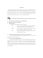
1. Overview
The Highspeed Programmable Attenuator Models 6010/6011/6012/6013, the 6010 series, provide
attenuation of up to 80dB in steps of 0.05 dB and a minimum program step time of 2µs. The four models
cover a wide frequency range of 1.5GHz – 13.5GHz. The 6010 series offers high accuracy, stability and
many features, yet are easy to use.
Due to the favorable price/performance ratio, the
6010/6011/6012/6013 attenuators are put to use in a diverse range of applications.
Features:
2 µs per word maximum switching speed (program readout clock speed) when in program
mode
Wide attenuation range of 80dB for program and manual mode
Minimum attenuation step size of 0.05dB
Program run modes
The program can be executed in free run, burst, or gate mode.
FREE
The program comprising of attenuation data and Pause information is
run continuously without the need of external trigger signals.
BURST
Each rising edge of the trigger signal applied to TRIG IN triggers
execution of the program memory. Pause Time is ignored.
GATE
The program (readout period) followed by the pause time is run while
the TRIG IN signal is TTL high.
Pause Time can be defined by number of clock cycles or by absolute time value
The Pause Time is the time interval in between program steps. It can be set in one-clock
increments or as a time value in 100 µs steps.
Software for creation of attenuation profiles
The 6010 series includes software to create and edit attenuation profiles and transfer the
attenuation data points via the RS-232C interface to the instrument’s internal memory (RS-232C
communication cable is included.)
The Software is intuitive and Windows98/Me/2000/XP/Vista
compatible. The program’s large capacity and high resolution (memory depth of 128k words, 8 bits per
word) and support of clock frequency of up to 500 kHz makes the 6010 series an ideal tool for a broad
range of applications.
1
2. Specifications
2.1 Performance
Model 6010
Model 6011
1.5 to 4.5 GHz
3.0 to 9.0 GHz
< 1.5 @ 2 to 4 GHz
< 1.7 @ 4 to 8 GHz
< 2.0 @ 1.5 to 4.5 GHz
< 2.2 @ 3 to 9 GHz
Insertion loss
< 2.3 dB @ 2 to 4 GHz
< 3.0 dB @ 4 to 8 GHz
(0 dB setting)
< 2.6 dB @ 1.5 to 4.5 GHz
< 3.3 dB @ 3 to 9 GHz
Model 6012
Model 6013
4.5 to 13.5 GHz
1.95 to 5.85 GHz
< 1.8 @ 6 to 12 GHz
< 1.6 @ 2.6 to 5.2 GHz
< 2.2 @ 4.5 to 13.5 GHz
< 2.1 @ 1.95 to 5.85 GHz
Insertion loss
< 3.5 dB @ 6 to 12 GHz
< 2.6 dB @ 2.6 to 5.2 GHz
(0dB setting)
< 3.8 dB @ 4.5 to 13.5 GHz
< 2.9 dB @ 1.95 to 5.85 GHz
Frequency range
VSWR
Frequency range
VSWR
Attenuator
Setting range
0 to 80 dB
Setting resolution
0.05 dB
Accuracy
±0.5dB @ 0 to 10dB
(at center of frequency range
and +10dBm input)
±0.8dB @ >10 to 30dB
±1.0dB @ >30 to 50dB
±1.5dB @ >50 to 64dB
±2.0dB @ >64 to 74dB
±3.0dB @ >74 to 80dB
Impedance
50 Ω nominal
Filter
1 µs to 3 ms, 1-3 step
Maximum input level
100 mW, either CW or peak power
Input damage level
0.8W average power
20W peak power of 1 µs pulse
Input/output connectors
SMA
Readout clock input
Input level
TTL
Maximum frequency
500 kHz
Input impedance
10 kΩ ±5%
Minimum pulse width
200 ns (for TTL low and high)
2
Input damage level
±20V (DC + peak AC)
Connector
BNC
Trigger input
Input level
TTL
Input impedance
10 kΩ ±5%
Minimum pulse width
> 1 µs
Input damage level
±20V (DC + peak AC)
Connector
BNC
SYNC output
Output level
TTL
Rise / Fall time
< 100ns
Output impedance
approximately 100 Ω
Connector
BNC
Functions
Attenuation mode
Manual and Program
Program mode
Program length
8 to 131072 words, (can be set in one word steps)
Readout clock
Internal clock
100 Hz to 500 kHz, 1-2-5 step
External clock
DC to 500 kHz
Pause Time
Clock setting
0 to 65535 clocks adjustable in 1 clock cycle increments
Time setting
0 to 6.5535sec (in 100µs increments)
Program execution mode
Non volatile program memory
Free, Burst, Gate
Program data is automatically saved when power is turned off.
Software for creating attenuation programs
3
Supported OS
Windows98/Me/2000/XP/Vista
Waveform creation
Standard waveforms
Sine, Triangle, Square, Ramp, sin x/x, (1-ε-ax),
ε-ax and DC
Parameters
Data length, Amplitude, Offset, Number of Cycles, Phase, Duty Cycle
(only Square wave), Zero cross (only sinX / X), Damp Factor
Straight line
Connect two or multiple points with a straight line
Math Functions
+, -, ×, Clipping, Absolute, Mirror, Resize, Offset
Editing options
Cut, Copy, Paste, Undo, Delete
File menu
New, Open, Close, Save, Save as, Data import,
Data export, Print, Printer setup, Transmit, Exit
Other
Display
LCD (backlit. 2 rows of 20 characters)
Interface
RS-232C
Baud rate
GPIB
Standard
2,400 to 57,600
Standard
General
Operating temperature
0 to 40°C (Specifications guaranteed at 23 ±5°C)
Operating humidity
less than 40°C / 80%RH (Guaranteed at less than 28°C / 80%RH)
Storage temperature
-10 to +60°C / less than 80%RH
Power Supply
90 to 132VAC / 180 to 250VAC
(selectable by a switch located on rear panel)
Weight
approx. 10 lbs (4.5kg)
Dimensions
8.11” (W) × 4.53” (H) × 14.18”(D) (excluding projections)
260 (W) × 115 (H) × 360 (D) mm (excluding projections)
Standard accessories
Operating manual (1pc), Power cord (1pc), Fuse (1pc),
Installation CD for creating attenuation profiles (1pc), RS-232C cable (1pc)
4
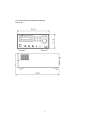
2.2 External appearance and dimensions drawing
Units in mm
5
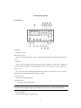
3. Description of panels
3.1 Front panel
①POWER
- Main power switch.
②READ CLOCK IN
- READ CLOCK input terminal. Apply an external clock signal with a maximum of 500 kHz to this
input.
③TRIG IN
- Apply a TTL level trigger signal to this terminal when in BURST or GATE mode. Readout of
attenuation data is triggered by rising edge (BURST mode) or when signal is TTL high (GATE mode).
④SYNC OUT
- TTL level Output signal, indicates start of readout period when in program mode. The Sync signal is
programmable, see DLxxxx command in chapter 6 for details
⑤ATTEN IN/OUT
- Attenuator's input/output terminal.
⑥ATTEN OUT/IN
-
Attenuator's output/input terminal.
CAUTION: Do NOT apply an input signal to both ATTEN IN/OUT terminals at the same time.
:⑦ATTEN MODE
- Key for selecting manual or program mode.
6
⑧READ CLOCK
- Key for selection of program memory read clock frequency.
⑨READ MODE
- Key for selecting BURST, GATE or FREE program execution mode.
⑩ATTEN
- Key for setting attenuation values in manual mode.
⑪PROGM LENGTH
- Key for setting the program memory length.
⑫SET UP
- Key for interface configuration.
⑬FILTER
- Key for setup of attenuator switching response time.
⑭PAUSE TIME
- Used for setting of program pause time.
⑮ENTER
- Used to confirm front panel entries
⑯
- Move cursor left.
⑰
- Move cursor right.
⑱ROTARY KNOB
- Increases or decreases the displayed numeric value.
Turn clockwise to increase and
counterclockwise to decrease values.
⑲LIQUID CRYSTAL DISPLAY
- Letters can be displayed in two lines (up to 20 letters per line). The settings of all parameters such
as ATTN MODE, READ CLOCK, PROGM LENGTH, READ MODE and FILTER are displayed.
7
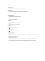
3.2 Rear panel
①AC line input
- Connector for supplying AC power to the instrument. Use the provided power cord to connect to a
power outlet. The AC voltage range is 90 - 130V or 180 - 250V. Make sure that the supplied
voltage is within this range. The AC receptacle also incorporates a fuse holder. Use a slow blow
fuse of 1.5A for 90 - 130VAC, or a slow blow fuse of 0.8A for 180 - 250VAC operation.
②AC line voltage select switch
- The switch is used to select 90 - 130VAC or 180 - 250VAC operation. Make sure your selection
matches the supply voltage in your area
③Earth terminal for protection
- For safety reasons, if the power outlet is not of 3-prong type, make sure to connect this terminal to
Earth Ground.
④Fan motor
-
Do not obstruct the airflow by placing objects in the vicinity of the vent hole.
⑤RS-232C
- Connector for RS232C communication. Communication with a PC is performed at 2,400 - 57,600
bps.
⑥GPIB
- Connector for GPIB communication.
8
4. Operation
4.1 Manual and program mode
- Select the attenuator control mode. The cursor on the screen moves to [MANUAL] or [PRGM] at
positions indicated below when the <ATTN MODE> key is pressed.
[MANUAL] mode screen
MANUAL 23.45dB
10μs
[PRGM] mode screen
PRGM 500KHz L:131072
P:6.5535s FREE 10μs
- Toggle between [MANUAL] and [PRGM] mode by turning the rotary knob
① [MANUAL] mode
The attenuation value set by <ATTEN> remains active.
② [PRGM] mode
The attenuation value is controlled by the program stored in internal program memory.
A program of up to 128K words can be stored. (An attenuation program can be created and
downloaded to the instrument’s memory using the provided attenuation program software or by
sending remote commands and data from a custom program)
4.2 ATTEN
- Set the attenuation level. The cursor moves to the xx.xx dB position when the <ATTEN> key is
pressed. This is valid in [MANUAL] mode only.
MANUAL 23.45dB
10μs
- Adjust the attenuation value within the range of 0.00dB - 80.00dB using the cursors and rotary knob.
Press the < key to move towards the most significant digit and press the > key to move towards the
least significant digit.
9
4.3 FILTER
- Set the attenuator switching response time. The cursor moves to the position indicated below when
the <FILTER> key is pressed. This parameter can be set in either [MANUAL] mode or [PRGM]
mode.
[MANUAL] mode example:
MANUAL 23.45dB
10μs
[PRGM] mode example:
PRGM 500KHz L:131072
P:6.5535s FREE 10μs
- Filter Response time can be entered in 1-3 steps in the range of 1 µs – 3 ms using the rotary knob.
Note: Use the built-in filter to reduce switching transients. To set the filter response time appropriately in
relationship to the readout clock, a value of 1/2 to 1/8 of the clock period is recommended.
4.4 READ CLOCK
- Select the program memory read clock. The cursor moves to the position indicated below when the
<READ CLOCK> key is pressed. This parameter is valid in [PRGM] mode only.
PRGM 500KHz L:131072
P:6.5535s FREE 10μs
- [MANU], [EXT], [100Hz] - [500kHz] can be selected using the rotary knob.
① When [MANU] is selected, one clock cycle can be generated by pressing the <ENTER> key.
② When [EXT] is selected, the signal applied to terminal READ CLOCK IN is used as the clock.
③ When the range of [100Hz] - [500kHz] is selected, the internally generated clock is used.
4.5 PRGM LENGTH
- Set the program memory length. The cursor moves to the position indicated below when the
<PRGM LENGTH> key is pressed. This is valid in the [PRGM] mode only.
10
PRGM 500KHz L:131072
P:6.5535s FREE 10μs
-
Move the cursor using cursor keys, and set a value in the range of 8 - 131072 using the rotary knob.
It is provided, however, that the upper limit depends on the date length in the program memory.
- Press the < key to move towards the most significant digit and press the > key to mode towards the
least significant digit.
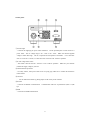
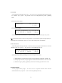
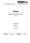
4.6 PAUSE TIME
- The pause time is defined as the interval between readout periods. The first pause time is the time
interval between the first and second readout period.
Figure 1: Readout period and Pause time
The screen below appears when the PAUSE TIME key is pressed. Highlight and select one of the
parameters [TIME], [CLOCK] or [OFF]. The current setup is displayed in the right upper part of the
screen. This parameter is valid in the [PRGM] mode only.
PAUSE:
TIME
TIME
CLOCK
0.0000s
OFF
Note: During the Pause time, the last attenuation value in the program remains active.
① When [TIME] is selected, the main screen is displayed and the cursor moves to the position
indicated below.
PRGM 500KHz L:131072
P:6.5535s FREE 10μs
- Move the cursor using the cursor keys and set a value in the range of 0 s - 6.5535 s using the rotary
knob. The cursor moves towards the most significant digit when < is pressed and towards the least
significant digit when the > key is pressed. Values can be set with 100 µs resolution.
11
② When [CLOCK] is selected the main screen is displayed and the cursor moves to the position
indicated below.
PRGM 500KHz L:131072
P:6.5535s FREE 10μs
- Move the cursor using the cursor keys and set a value in the range of 0 - 65535 using the rotary knob.
The cursor moves towards the most significant digit when < is pressed and towards the least significant
digit when the > key is pressed.
- Note: The applicable clock signal is what was selected by READ CLOCK.
③ When [OFF] is selected, the main screen is displayed.
PRGM 500KHz L:131072
P:6.5535s FREE 10μs
- Setting the Pause time to OFF is equivalent to setting the parameters [TIME] or [CLOCK] to zero.
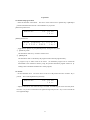
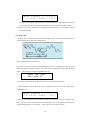
4.7 READ MODE
- Select the program read mode. The cursor moves to the position indicated below when the <READ
MODE> key is pressed. This is valid in [PRGM] mode only.
PRGM 500KHz L:131072
P:6.5535s FREE 10μs
- Select one of 3 possible modes [FREE], [GATE] and [BURST] using the rotary knob.
Figure 2: Readout period and Pause time for the 3 operating modes
12
① When [FREE] is selected, the program is read (i.e., run) and a delay of the pause time is created.
This is repeated continuously.
② When [GATE] is selected, the program read and pause times are repeated while the signal input to
terminal TRIG IN is TTL High or while the <ENTER> is pressed (and held).
③ When [BURST] is selected, program read is executed at the rising edge of the signal applied to
terminal TRIG IN or when the <ENTER> key is pressed. The pause time value is ignored.
4.8 SET UP
① The setup is used for the configuration of communication parameters. The screen below appears
when the <SET UP> key is pressed.
SET UP:
RS232C GPIB EXIT
②When RS-232C is selected, the following screen is displayed.
Select the baud rate of RS-232C using the rotary knob and confirm with the <ENTER> key.
(2400, 4800, 9600, 19200, 38400, 57600)
SET UP - RS232C
BaudRate: 57600
③When GPIB is selected, the following screen is displayed.
Select the GPIB address (0 - 30) using the rotary knob and confirm with the <ENTER> key.
SET UP - GPIB
ADDRESS: 10
13
4.9 Setup menu table
ATTEN MODE
MANUAL
ATTEN
PRGM
READ CLOCK
PRGM LENGTH
PAUSE TIME
TIME
CLOCK
OFF
READ MODE
FILTER
SET UP
RS232C
GPIB
4.10 List of abbreviations
ATTEN‥ ‥ ‥ ‥ ‥ Attenuator
PRGM‥ ‥ ‥ ‥ ‥ ‥ Program
Trig‥ ‥ ‥ ‥ ‥ ‥ Trigger
Sync‥ ‥ ‥ ‥ ‥ ‥ Synchronize
14
5. Software for creating attenuation profiles
5.1 Minimum system requirements
- Windows PC with Windows 98/NT/2000/XP/Vista
- CD-ROM drive
- RS-232C port (for data transfer)
5.2 Installation and start-up
① Start SETUP.exe contained on the CD-ROM. The setup utility will start. For installation, follow
the on-screen instructions.
② Start MAS800.EXE. The attenuation program software will be launched
5.3 Menu structure
FILE
NEW
Open...
Close...
Save
Save As...
Data Import...
Data Export...
Printer Setup...
Print
Transmit...
Exit
Edit
Undo
Cut
Copy
Paste
Delete
15
View
Horizontal Zoom
Zoom In
Zoom Out
Zoom Min
Zoom Max
Vertecal Zoom
Zoom In
Zoom Out
Zoom Min
Zoom Max
Time
X Scale
Length
Ampl
Y Scale
Full Scale
Math
Add Wave Form
Add Wave Buffer
Sub Wave Form
Sub Wave Buffer
Mul Wave Form
Mul Wave Buffer
Clipping
Abs
Mirror
Horizontal
Offset
Vertical
Smooth
Resize
Options
Free Hand
Line
Select
Select All
Wave Form...
Tool Bar
Status Bar
View Window
Help
About
16
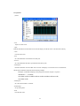
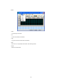
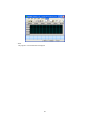
5.4 Operation
(1) File
- New
Open a new edit screen.
- Open
Read the attenuation waveform data from a File and display it in the edit screen. The file format is binary.
- Close
Close the edit screen.
- Save
Save the attenuation waveform data to a binary file
- Save As…
Save the attenuation data with a specified file name (binary file)
- Data Import…
Read the attenuation waveform data from a text file and display it on the edit screen. The attenuation
data must be formatted as illustrated in the following example:
Example: 1000 kHz sampling clock (program readout), length = 10 points
SAMPLING = 1.000KHz,,
20.00dB,20.00dB,20.00dB,20.00dB,20.00dB,60.00dB,60.00dB,60.00dB,
60.00dB,60.00dB,
- Data Export…
Save the waveform data to a text file.
- Printer Setup…
Set up of the printer.
- Print
Print the edit screen.
17
- Transmit…
Transfer the attenuation data to the 6010/6011/6012/6013
- COM Port
Configure your PC’s COM Port
- Baud Rate
Select the baud (transfer) rate.
- Data Length
Set the data size to be transferred (8 – 131072 words).
- Filter
Select the attenuator switching response time.
- Read Clock
Select the program memory read clock rate.
- Read Mode
Select the program read mode.
- Pause time
Select and set the pause time between readout periods.
18
(2)Edit
- Undo
Cancel the previous action.
- Cut
Cut the selected data to the buffer.
- Copy
Copy the selected waveform data to the buffer.
- Paste
Paste the cut or copied data in the buffer to the selected position.
- Delete
Delete the selected data.
19
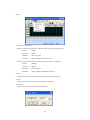
(3)View
- Horizontal / Vertical Zoom
Enlarge or reduce the horizontal axis, with the left end of the screen as the reference.
Zoom In
--- Enlarge
Zoom Out
--- Reduce.
Zoom Max
--- Maximum zoom
Zoom Min
--- Show complete time base (no zoom)
Enlarge or reduce the vertical axis, with the center of the screen as the reference.
Zoom In
--- Enlarge
Zoom Out
--- Reduce
Zoom Max
--- Maximum zoom
Zoom Min
--- Show complete 0-80 dB scale (no zoom)
- X Scale
Toggle the units of the horizontal axis between time and number of data points.
- Y Scale
Toggle the units of the vertical axis between dB and % of full scale.
- Select Scale
Change setting of scale in Hz (readout clock frequency)
20
(4)Math
- Add Wave Form
Add a standard waveform, to the wave form in the editing window.
- Add Wave Buffer
Add the cut or copied data in the buffer to the specified waveform.
- Sub Wave Form
Subtract a standard waveform from the wave form in the editing window
- Sub Wave Buffer
Subtract the cut or copied data in the buffer from the specified waveform.
- Mul Wave Form
Multiply a standard waveform with the waveform in the editing window
- Mul Wave Buffer
Multiply the cut or copied data in the buffer with the specified waveform.
To perform the above Add/Subtract/Multiply operations, do the following:
a) Select the mathematical operation you want to perform
b)Using the mouse, highlight the area of the waveform in the editing window to which you want to apply
the selected operation.
21
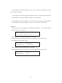
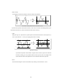
-Clipping
Limit (clip) the waveform to the limit points (Y1, Y2) within the horizontal range defined by (X1, X2)
‚w‚P
‚w‚Q
‚w‚P
‚x‚P
‚x‚P
‚x‚Q
‚x‚Q
‚w‚Q
The waveform before and after clipping
To perform this operation: Select Clipping. Click on the waveform in the editing window, press and
hold the left mouse key, define a horizontal line then release the mouse key.
- Abs (absolute value)
Apply the operation abs(f(x)) to the graph f(x) between X1 and X2
‚w‚P
‚w‚Q
‚w‚P
‚x‚P
‚w‚Q
‚x‚P
The waveform before and after applying the abs (fx(x)) operation
To perform this operation: Select Abs. Click on the waveform in the editing window, press and hold
the left mouse key, define a horizontal line then release the mouse key.
- Mirror/Horizontal
On the graph f(x) between X1 and X2, reflect f(x) about a vertical line located at X1 + ½*(X2-X1)
‚w‚P
‚w‚Q
‚w‚P
‚w‚Q
gg
The waveform is being reflected about a vertical line
To perform this operation: Select Mirror/Horizontal from the menu. Click on the waveform in the
editing window, press and hold the left mouse key, create a white space centered around the vertical line
and release the mouse key
22
- Mirror/Vertical
On the graph f(x) between X1 and X2, reflect f(x) about a horizontal line
‚w‚Q
‚w‚P
‚w‚Q
‚w‚P
g
The waveform is being reflected about a horizontal line (x-axis)
To perform this operation: Select Mirror/Vertical. Click on the waveform in the editing window, press
and hold the left mouse key, define a horizontal line then release mouse key
- Offset
Bring the range (X1, X2) between 2 specified points in the horizontal direction to the end point (Y1)
in the vertical direction. You may see clipping if the offset is too large.
‚w‚P
‚w‚Q
‚w‚P
‚x @‚l‚`‚w
‚w‚Q
‚x @‚l‚`‚w
‚x‚P
‚x‚P
‚x @‚l‚h‚m
‚x @‚l‚h‚m
Apply offset to waveform
To perform this operation: Select Offset. Using the mouse, describe a square area around the
waveform, working your way from the bottom to the top of the screen. The height of the
square defines the offset value applied to the curve within the width of the square box
- Resize
Resize the data along the vertical or horizontal axis by selecting a value between 0 - 99.9%.
23
The data will be compressed according to the factor selected.
Example: The maximum amplitude of a sine wave profile is 20dB. By selecting 50 for the Y size, all
amplitude values will be decreased by 50% and the maximum amplitude will be 10 dB. The time axis will
be adjusted accordingly
(5) Option
- Free Hand
This mode is for free-hand drawing of attenuation profiles. Press and hold down the left mouse button
to draw.
Drawing terminates when the mouse button is released.
The free hand waveform is
automatically connected to the existing waveform.
Or: Modify an existing waveform by clicking on the waveform, then dragging it to a new area.
- Line
Draw straight lines by clicking in the waveform window once, then move the cursor and left click
again.
Drawing terminates when the mouse button is released.
24
The straight line waveform is
automatically connected to the existing waveform.
Or: Modify an existing waveform by clicking on the waveform, then dragging it to a new area.
- Select
Select a portion of the wave that is the object of the edit or arithmetic operation.
- Select All
The entire waveform is selected.
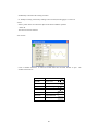
- Wave Forms
Create a standard waveform.
It cannot be created unless the waveform window is open.
standard waveforms are:
SIN
Sine wave
SQUARE
Square wave
TRIANGLE
Triangle wave
RAMP
Synchronizing
SIN(X)/X
Sinc function
EXP RISE
Exponential rise
EXP FALL
Exponential fall
DC
DC voltage
25
The
Parameter
Setting range
LENGTH [W] (number of data)
8 – 131072
All waveforms
1 – 100
All except DC
AMPL [dB] (amplitude)
0 – 80 dB
All waveforms
OFFSET [dB] (offset)
0 – 80dB
All except of DC
PHASE [deg] (phase)
0 – 360°
All except of DC
CYCLES (cycle)
DUTY [%]
(duty cycle)
ZERO CROSS
DAMP FACT (attenuation)
0.01 – 99.99%
0 – 100
-15 - +15
Applicable waveform
SQUARE and TRIANGLE
Sin(X)/X
EXP RISE and EXP FALL
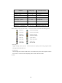
Select whether or not to select the toolbar. Icons in the tool bar correspond to the following menu.
File: New
Zoom in horizontally
File: Open
Zoom out horizontally
File: Save
Zoom in vertically
Edit: Undo
Zoom out vertically
Edit: Cut
Option: Select
Edit: Copy
Option: Free Hand
Edit: Paste
Option: Line
Edit: Delete
File: Transmit
- Status Bar
Toggle the display of the status bar. When the status bar is displayed, the current grid point and the
time appear underneath the screen.
- View Window
Turn the display of the bottom window on/off. This window always shows the complete waveform
and is useful as a reference when manipulating the waveform in the main window.
(6) Help
26
- About
The program’s version information is displayed.
27
6. Remote interface
6.1 RS232C protocol
Configuration of RS232 interface:
Transfer rate:
2400/4800/9600/19200/38400/57600
Stop bit:
1 bit
Character length:
8 bits
XON-OFF:
None
Parity:
None
Note: The supplied R232C cable is configured as cross or null-modem over cable
Command syntax and protocol
See section 6.3 for a complete list of commands. A command consists of the ASCII letters for the command
and a data part. There is no blank between the command and the data part. Some commands do not contain
a data part. The data parts are ASCII characters. All commands must be terminated with CRLF (carriage
return/line feed).
The transmission of each command must be preceded by a “CY” handshake. The computer program must
send the ASCII character 'C' to the 6010. Then the 6010 attenuator responds by sending 'Y' followed by
CRLF. Only after successful exchange of this handshake will a command be accepted by the attenuator.
Upon receipt of a valid command, the 6010 responds with a string “OK”, followed by CRLF. The sequence
for a command transmission is:
PC
"C"
6010
------>
<------
"RCL1KHZ”+CRLF
"Y"+CRLF
------>
<------
"OK"+CRLF
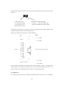
Download command DLxxxx
The DLxxxx command can be used to transfer a block of arbitrary attenuation data to the instrument using
a single command. xxxx is a decimal value between 8 – 131071 and denotes the length or number of
attenuation data points to be transmitted. The attenuation data will be transmitted immediately following
the DLxxx command. As with the other commands, the DLxxxx command must be preceded by a “CY”
handshake. The data are terminated by CRLF and the attenuator will acknowledge receipt of the data with
‘OK’. If data transmission was unsuccessful, the instrument will respond with ‘ERR’.
28
Each attenuation value is represented by one 16 bit word. The hexadecimal code for this word is coded as
followed:
8640
Controls the SyncOut
8h: Sync pulse TTL High
Fh: Sync pulse TTL Low
Other values are not used
Attenuation value: three Hex digits.
Conversion: = Real ATT level(dB)/0.05
1h represents 0.05dB, 640h represents 80dB
Each data word is transferred in the order of Low Byte first, High byte second. 80dB or 8640h would be
transmitted as 4086h. (Note: h denotes hexadecimal value)
Sequence for transmission of an arbitrary waveform data block:
PC
6010
"C"
------>
<-- "Y"+CRLF
"DL10;"
------>
<-- "Y"+CRLF
8064
80C8
8064
80C8
8064
F0C8
F064
F0C8
F064
10words
Actual transfer: 6480h, 80C8h…
F0C8
CR LF
"C"
------>
<-- "Y"+CRLF
"LEN10”+CRLF ---->
<-- "OK"+CRLF
In this example, the attenuation level toggles between 5 dB and 10dB for 10 times. Assuming that the
sample clock was set to 1KHZ, each value is held for 1ms and the total execution time is 10ms.
The
Sync pulse will be TTL: high during the first 5ms and TTL low during the last 5ms.
6.2 GPIB protocol
The command syntax and protocol is identical to the RS232 interface except for the “CY” handshake,
29
which is not used. CRLF (EOI) is transmitted as a termination string.
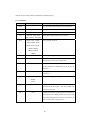
6.3 Command list
Command
Data part
MAN
---
The control mode of the attenuator is set to MANUAL
PRG
---
The control mode of the attenuator is set to PROGRAM
– 80.00
Set the attenuation level when in MANUAL mode.
ATT
FLT
0.00
1US, 3US, 10US, 30US,
Explanation
Change filter constant (units are in µs and ms).
100US, 300US, 1MS, 3MS
RCL
MANU, EXT, 100HZ ,
Set the program read clock.
200HZ, 500HZ, 1KHZ,
2KHZ, 5KHZ, 10KHZ ,
20KHZ, 50KHZ,
100KHZ,200KHZ ,
500KHZ
LEN
PTI
8 –
131072
0.000S – 6.5535S
Set the program length.
Set the pause time. If PTI is not set, this parameter will
automatically be set to zero (no pause time)
PCL
0 – 65535
Set the pause time is in number of clocks. If PCL is not
set, this parameter will automatically be set to zero (no
pause time)
POF
---
Pause period is turned off (identical to setting PCL or
PTI to zero).
MOD
FREE
Specify how the program is triggered.
BURST
GATE
RMT
---
When the instrument is set to remote mode, it cannot be
operated from the front panel. Push the "ENTER" key
to return to local mode.
DL
xxxx;
Configure the length of the data block to be transferred to
the instrument. xxxx should generally be set to the same
value as the LEN parameter, however it is possible to set
LEN to a value equal or less than xxxx
30
6.4 Example program
Below is a code sample created with Visual Basic 6.0. The complete Visual Basic project, including the
executable, can be downloaded from the B+K Precision website at www.bkprecision.com.
Dim CrLf As String
CrLf = Chr$(&HD) + Chr$(&HA)
Dim Buffer(1) As Byte
******* transmit DL8 command to prepare for transmission of 8 word data block ****
*******Function Call WaitRes() receives 3 bytes, in this case ‘Y’+ CRLF **********
MSComm1.Output = "C"
Call WaitRes(3)
MSComm1.Output = "DL8;"
Call WaitRes(3)
**** transmit 8 attenuation values of type word **********
**** set the Sync pulse, move high byte to low byte and low byte to high byte position *****
For i = 1 To 8
If Check1(i) = 1 Then sync = "8" Else sync = "F"
s = sync + Right$("000" + Hex$(TextATT(i) / 0.05), 3)
Buffer(0) = Val("&h" + Left(s, 2))
Buffer(1) = Val("&h" + Right(s, 2))
For j = 1 To Word(i)
MSComm1.Output = Buffer
Next
Next
MSComm1.Output = CrLf
******set the program length to 8 *************
**Function Call WaitRes() receives 3 and 4 bytes respectively, in this case ‘Y’+ CRLF and OK’+ CRLF*
Call WaitRes(4)
MSComm1.Output = "C"
Call WaitRes(3)
MSComm1.Output = "LEN" + CStr(dl) + CrLf
Call WaitRes(4)
31
1
Service Information
Warranty Service: Please return the product in the original packaging with proof of purchase to the
address below. Clearly state in writing the performance problem, how to recreate it, and return any leads,
probes, connectors and accessories that you are using with the device.
Non-warranty Service: Return the product in the original packaging to the address below. Clearly state
in writing the performance problem, how to recreate the problem, and return any leads, probes,
connectors and accessories that you are using with the device. Customers not on an open account must
include payment in the form of a money order or credit card. For the most current repair charges please
visit www.bkprecision.com and click on “service/repair”.
Return all merchandise to B&K Precision Corp. with pre-paid shipping. The flat-rate repair charge for
Non-Warranty Service does not include return shipping. Return shipping to locations in North American
is included for Warranty Service. For overnight shipments and non-North American shipping fees please
contact B&K Precision Corp.
B&K Precision Corp.
22820 Savi Ranch Parkway
Yorba Linda, CA 92887
www.bkprecision.com
714-921-9095
Include with the returned instrument your complete return shipping address, contact name, phone
number and description of problem.
Limited One-Year Warranty
B&K Precision Corp. warrants to the original purchaser that its products and the component parts thereof
will be free from defects in workmanship and materials for a period of one year from date of purchase.
B&K Precision Corp. will, without charge, repair or replace, at its option, a defective product or
component parts. The returned product must be accompanied by proof of the purchase date in the form of
a sales receipt.
To obtain warranty coverage in the U.S.A., this product must be registered by completing a warranty
registration form on www.bkprecision.com within fifteen (15) days of purchase.
Exclusions: This warranty does not apply in the event of misuse or abuse of the product or as a
result of unauthorized alterations or repairs. The warranty is void if the serial number is altered,
defaced or removed.
B&K Precision Corp. shall not be liable for any consequential damages, including without limitation
damages resulting from loss of use. Some states do not allow limitations of incidental or consequential
damages, so the above limitation or exclusion may not apply to you.
This warranty gives you specific rights and you may have other rights, which vary from state to state.
B&K Precision Corp.
22820 Savi Ranch Parkway
Yorba Linda, CA 92887
www.bkprecision.com
714-921-9095
1
OM-0712 Rev. 1.01
B&K Precision Corp.
Printed in Japan
22820 Savi Ranch Parkway
© 2007 B&K Precision Corp.
Yorba Linda, CA 92887, USA
TEL: 714-921-9095
www.bkprecision.com
1