1
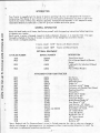
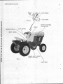
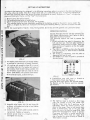
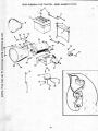
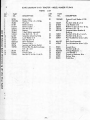
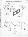
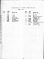
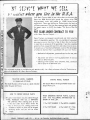
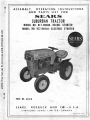
ASSEMBLY, OPERATING INSTRUCTIONS
AND PARTS LIST FOR
another free manual from www.searstractormanuals.com
SIEArt, S
SUBURBAN TRACTOR
MODEL NO. 917.99400 - RECOIL STARTER
MODEL NO. 917.99410 - ELECTRIC STARTER
SEARS
ROEBUCK AND CO.
PART NO. 6547H
SEARS, ROEBUCK AND CO.-U.S.A.
SIMPSONS-SEARS LIMITED-CANADA
PRINTED IN U.S.A.
TABLE OF CONTENTS
PAGE
DESCRIPTION
INTRODUCTION GENERAL INFORMATION OPTIONAL EQUIPMENT another free manual from www.searstractormanuals.com
PARTS IDENTIFICATION OPERATING CONTROLS
STARTER GENERATOR BELT 9
3
WHEEL WEIGHTS
9
3
STARTER AIR CLEANER
Recoil Starter Electric Starter SEAT POSITION 6
TO START ENGINE 6
WINTER CARE 6
TIRES 6
STORAGE INSTRUCTIONS 7
TROUBLE SHOOTING 7
HARD TO START
BELT ADJUSTMENT
8
11
11
ENGINE LACKS POWER PARTS LIST 8
10
10
ENGINE OVER HEATS 8
BRAKE ADJUSTMENT .
BRAKE LOCK 7
10
10
TRANSAXLE LUBRICATION 10
GENERAL LUBRICATION CHART 9
IMPORTANT BATTERY CARE
7
9
OPERATE TRACTOR ENGINE LUBRICATION
9
TOWING TRACTOR 5
BEFORE STARTING ENGINE
AIR CLEANER 5
PAGE
3
4
BATTERY INSTALLATION DESCRIPTION
HOW TO ORDER REPAIR PARTS 11,
11
12 thru 21
22
•
—2
SEARS
another free manual from www.searstractormanuals.com
ROEBL,K AND CO
. . . WE GUARANTEE the Sears Tractor to be free from defects in materials
and workmanship for a period of one (1) year from date of sale. This also includes
the gasoline engine which is warranted for a period of one (1) year by the gasoline
Should a defect appear within the guarantee period, we will, at our option, either
repair or replace the defective part without cost to you.
This guarantee does not cover free repair, replacement, or installation of parts
worn through normal use or to parts damaged due to accident, negligence, abuse
or improper use, or if the Tractor has been altered or adjusted by other than our
qualified serviceman.
We do not authorize any person or representative to make any other guarantee
or to assume for us any liability in connection with the sale of the Sears Tractor
other than those contained herein. Any agreements outside of or contradictory
to the foregoing shall be void and of no effect. This guarantee applies only to
those machines sold and operated in the United States and Canada.
INTRODUCTION
Your Tractor is ruggedly built for plenty of stamina and long life. You will delighted with its ease in
maneuvering. The design of your Tractor will give you the superior performance you have a right to demand of any tractor of this size. Properly adjusted, maintained and operated, it will respond to every
reasonable demand you make upon it, and will give you reliable service for years.
another free manual from www.searstractormanuals.com
GENERAL INFORMATION
Keep this book handy at all times, familiarize yourself with the operating instructions before beginning
to operate your tractor.
Each tractor is given a thorough inspection before shipment, however, it is important that it be again
thoroughly checked at the time of receipt, to ascertain if any damage has occurred in transit.
Your tractor is shipped complete.
1 Carton 634X1 10 HP Tractor with Electric Starter
1 Carton 634X9 10HP
Tractor with Recoil Starter
OPTIONAL EQUIPMENT
CATALOG NUMBER
BUNDLE NUMBER
9931
9934
606X80
634X4
9939
634X8
9960
626X6
DESCRIPTION
Three Point Hitch
Kit to Convert Recoil to Electric
Starter
Lighting Kit for Suburban W/Recoil
Starter
Pair of Wheel Weights
ATTACHMENTS FOR YOUR TRACTOR
Dis Harrow
606X4
9813
Drag Harrow
606X7
9814
Adjustable Foot
606X8
9815
Sweep- 14"
606X18
9816
Cultivator with 6" Sweep
606X5
9817
Cultivator with Double Point Shovel
606X6
9818
Weeding Hoes-Pair
606X12
9819
Hillers-Pair
606X13
9820
Shank and 6" Sweep
606X14
9821
Rotary Tiller 30"
634X12
9835
Front End Weight
606X31
9841
Middle Buster Blade 10"
575X81
5320
Corn Shovel 5" X 8"
575X83
5322
Leaf Mulcher - 42" Mower
606X52
9911
Replacement Blade 42" Mower
606X55
9912
Dump Rake with Teeth
575X66 and 606X58
9914
42" Grader Blade
9915
634X11
Cutter
Bar Mower
9918
606X78
Moldboard
Plow 8"
9927
606X73
42"
Rotary
Mower
9930
606X77
Snow Thrower
9932
634X5
Buldozer 42"
9938
634X6
Sears, Roebuck and Co. Simpsons-Sears Limited in Canada reserves the right to make any changes in
design and changes or improvements on its implements without imposing any obligation to install the
same upon its implements heretofore manufactured.
—3—
PARTS IDENTIFICATION
another free manual from www.searstractormanuals.com
FOOT PEDAL
— FOOT REST
FIG. B
CHOKE
IGNITION SWITCH
REMOTE CONTROL
(throttle lever)
LIGHT SWITCH
SHIFT LEVER
RANGE SHIFT LEVER
(High-Low Range)
FIG. A
FOOT REST
SETTING UP INSTRUCTIONS
A number at the beginning of a paragraph in the following instructions refers to an arrow in the adjoining figure except when otherwise stated. When R.H. (Right Hand) and L.H. (Left Hand) are used, it should be understood to
to mean from a position behind and facing the tractor (or direction of travel). Reference to "front" indicates the
engine and hood end of tractor, and the "rear" the transmission.
Remove carton from around tractor.
Cut banding holding tractor to crate bottom.
Check tire pressure, front tires 15 pounds, rear 8 pounds.
This suburban tractor has been completely assembled at the factory, except for the electric star-:-ar model. The
battery is shipped dry. Below are instructions for filling and installing battery. Lubricate the tractor and add
fuel.
NOTE: Use a good grade of regular, clean, fresh gasoline. Do not mix oil with gasoline. See Lubrication Chart.
another free manual from www.searstractormanuals.com
1.
2.
3.
4.
OPERATING CONTROLS
Become thoroughly familiar with the operating controls before starting engine. See Figures A and B,
Page 4 for location of controls.
The following controls are used to operate the
tractor:
1. Clutch and brake foot pedal is located on the
left side foot rest. The foot pedal operates a
combination brake and drive clutch. There are
three positions of operation on the foot pedal.
See Figure B.
a. The clutch is in DRIVE position when the pedal
is all the way out (i.e. when the foot is removed
from the pedal).
b. The clutch is in NEUTRAL when the pedal is
depressed half way or more.
c. The BRAKE is on when the pedal is pressed all
the way forward.
FIG. C
0
1. Fill battery with electrolyte and charge battery
as outlined in instructions in battery container.
2. Lift cowling and assemble clamp (B) to one of
two battery bolts (A). Flat washer and wing nut
above clamp. Hook the bolt clamp assembly into
rear of battery support and turn clamp to side,as
shown. Slide battery into position with terminals to center of tractor, as shown in Fig. C.
Oman C n 111.
Ofmlual
SPUD IN MPH
0
O 0 1.9
1.4 3.6
e
2.4
5.9
e
95.2.3
14.1.41.
Su. INOMICK a CO
i“ us, •
FIG. E
111.1.— A
2. Transmission gear shift lever is located at
front centcr of seat. See Figure A.
The gear shift lever selects the Forward speeds,
the Neutral, and the Reverse positions required.
See Fi g ure E.
FIG. F
FIG. D
3. Assemble other battery bolt (A) and clamp (B)
as shown, with washer and wing nut and tighten
wing nuts securely.
4. Connect starter switch cable (covered cable) to
(+) terminal. Tighten nut securely.
5. Connect ground strap to (—) negative terminal,
and tighten nut securely.
— 5—
3. The high-low range is located on R.H. frame
side just forward of R.H. rear fender. The
high-low range lever has 3 positions up for
high-range, center for neutral position, and
down for low range. There is two neutral positions in transmission, one on the gear shift
lever and, one on the high-low range lever. Both
levers must be engaged for tractor to operate.
Place gear shift lever in neutral position for
starting tractor. Place high low range lever
also in neutral for easier pushing of tractor or
when tractor is towed.
BEFORE STARTING ENGINE
LIFT COWLING
another free manual from www.searstractormanuals.com
1. To lift cowling, grasp each side of cowling,
at rear and pull outward and upward Lift
cowl ing to its extreme open position.
FIG. I
FOR RECOIL STARTER
1. Advance throttle lever to about 1/2 throttle.
2. Turn key clockwise to on position.
re (I) and
3. Grasp recoil starter handle See Figure
pull sharply to start engine. Do not allow
starter rope to snap back. Repeat until engine starts. Move choke control in about 2/3 of
the way. Gradually push control in as engine
warms up, before applying load.
NOTE: If engine does not start after serveral
pulls push in choke control. Check to see that
fuel shut off valve is open, fuel in tank and the
ignition key is turned on.
FIG. G
2. Engine crankcase is shipped with oil ready
for use. However check oil level before starting. If necessary, add oil to bring oil level up
to the fuel mark on the dip stick. Dipstick
must be screwed in tight for checking oil
level, and tractor should be level. NOTE: Do
not fill above full mark on dipstick. Engine
must be stopped when checking oil level. Refer to engine manual for grade and type of oil
to use.
3. Fill fuel tank with regular grade of clean
fresh gasoline, and open fuel shutt off valve
located near carburetor.
CAUTION: Before starting the engine, check to
see that the controls are as follows:
4. Transmiss ion gear shift lever must be in
neutral. Neutral is when gear shift lever is
free to move forward and backwards. It will
operate simi I iar to an automobile See Figure H.
FOR ELECTRIC STARTER
1. Advance throttle lever to about 1/2 throttle..
2. Pull choke control out to full choke position.
3. The ignition and starter key is located on L.H.
side of dashboard. Turn key clockwise to engage starter. When engine starts release key.
After engine starts push in choke control as engine warms up. Let engine warm up before applying load.
CAUTION: Do not run starter continuiously for more
then 30 seconds at a time.
If after several attempts, engine does not start, move
throttle control lever to FAST position. Wait for two
minutes and try again.
4.. After engine starts, move engine control lever
to FAST position.
FOR ALL MODELS
1. Engine speed between FAST and SLOW positions may be varied as desired.
2. To stop engine turn key in a counter clockwise
direction to off position. Key can be removed so
that children cannot start tractor.
FIG. H
TO START ENGINE
1. Pull out choke control to full choke position,
to start cold engine.
—6—
another free manual from www.searstractormanuals.com
TO OPERATE TRACTOR
ENGINE LUBRICATION
1. Try your tractor in a large, open space. Learn
start,
stop and reverse.
to
2. Start the engine and put the remote control
lever at about 1/2 throttle. Push down on foot
pedal, move gear shift lever and range lever to
speed desired. Release foot pedal slowly, and
tractor will start to move. After foot pedal is
fully released (clutch engaged) move remote
control lever to fast psoition. If ground travel
is too fast, depress foot pedal and shift to a
slower ground travel speed. Always select a
ground travel speed so that engine is not overloaded.
Do not shift gears while tractor is moving.
Important: Do not attempt to make any turns at
high speed or when operating on a hillside. Reduce speed when on hillsides so that if wheel strikes a hole, rut or ditch tractor will not tip.
Never release clutch quickly with remote control
position
(full throttle).
fast
at
If tractor becomes mired or in a hole try to back
than
drive forward.
out
rather
To stop tractor, push foot pedal all the way down,
move gear shift lever to neutral, set brake lock
and release foot pedal. Always check to make
sure brake lock will hold tractor secure. Shut off
and remove key from switch.
This will.prevent unauthorized children from start
ing tractor. Never leave engine running with tracor unattended.
TRANSAXLE LUBRICATION
1. Change oil in crankcase after first 2 hours of
operation Engine should be warm when oil is
changed.
2. To drain oil, unscrew pipe cap at lower front
end of engine and catcn usea oil in suitable
container. See Figure K.
3. Refill engine crankcase with oilasinstructed
under "Before Starting the Engine". Check oil
level after each five hours of operation and add
oil, if necessary, to bring to correct level.
4. After first oil change, oil should be changed
atter each 25 hours of operation.
LUBRICATION CHART
FIG. J
• 1. Check oil in transaxle every 50 hours of operation.
2. Change oil in transaxle after 500 hours of operation: To drain oil unscrew drain plug on
lower L.H. side of transaxle, and catch oil in
suitable container, see Figure J.
3. To fill transaxle use 5 qts. of Allstate SAE 30
motor oil for service MM or MS. Fill through
filler plug as shown in figure J, NOTE: Rear
wheel is shown removed for illustration.
4. To check oil level, remove filler plug from
transaxle. Oil level should be even with this
plug.
There are only 5 grease fittings on this tractor:
1. Grease front spindles and wheels every five
hours. Two slots of grease each fitting.
2. Grease steering sector every 5 hours, two
shots of grease.
3. Check oil in engine crankcase at least every
5 hours of operation. Change oil every 25
hours of normal operation, in extremely dirty or
dusty conditions change oil every 15 to 20
hours of operation.
4. Check oil in transaxle every 50 hours of operation. Change oil in transaxle every 500 hours
of operation.
serveral drops of oil to all pivot points
5. Apply
every 5 hours of operation.
BELT ADJUSTMENT
IDLER BRACKET
FRAME
_ IDLER PULLEY
BELT
62-"
another free manual from www.searstractormanuals.com
FLAT IDLER
FOOT PEDAL
1. Loosen bolt in flat idler and frame, and push idler and bolt down in slot of frame until center of idler
pulley on idler bracket (just back of engine) is 6-12 inches above frame as shown. Tighten bolt in
flat idler and frame securely.
NOTE: Foot pedal should be in vertical or just back of vertical position with clutch engaged. New
belts will stretch after a few hours of operation, then after initial stretch, adjustment is
seldom necessary, so adjust belt after 1st 10 hours of operation.
IDLER PULLEY
FLANGED NUT
TURNBUCKLE
41"
BRAKE LOCK
FOOT PEDAL
BRAKE ADJUSTMENT
To adjust brake, loosen nut back of turnbuckle and turn turnbuckle (clockwise when standing in front
of tractor) one turn at a time until foot pedal has between 4 to 4''2 inches of travel from clutch engageed to full brake position, or center of idler is about 4 1 4 to 4 1 2 above frame as shown.
Tab on idler bracket will deflect belt slightly. Tighten jam nut against turnbuckle to lock turnbuckle
in position. Keep brake properly adjusted especially in hilly terrain.
BRAKE LOCK
The flanged nut is adjustable forward or backward on rear brake rod so that lock assembly will hold
brake full on when parking lock is pulled up (lock position). Tighten jam nut against flanged nut to
lock flange nut in position. As brake band wears, flanged nut will have to be readjusted.
another free manual from www.searstractormanuals.com
MAINTENANCE AND SERVICE
FIG. N
FIG. L
STARTER GENERATOR BELT
AIR CLEANER
1. Remove 3 screws (A) holding belt guard to engine.
2. Loosen bolt (B) in generator adjusting strap
and generator, move starter generator back to
tighten belt and tighten bolt (B) securely.
Belt should be tight enough to prevent belt
tractor.
when
starting
slippage
Clean air cleaner periodically. To clean carburetor
air cleaner remove wing nut that holds air filter
cover to bracket and remove cover.
1. Pull element trom bracket.
2. Tap element lightly to dislodge any dirt etc.
which has accumulated on element. Compressed
air may also be used to clean air cleaner. Blow air from center to outside. This is a dry
type air cleaner, so do not oil or wash in gasoline or other solvent.
3. Clean cover and bracket and replace element.
Wing nut must be kept tight. If air cleaner becomes to dirty/ engine will not receive sufficient air to run properly, At the start of each
season it is recommended that a new element
be instal led.
WHEEL WEIGHTS:
Rear wheel weights are available where extra
draw bar pull is desired. When attaching weight to
the wheel the convex side should be out. Insert
the bolts from the outside through the holes, which
have a deep recess on the concave (inner) side,
and holes in wheel disc Another wheel weight can
be added by placing nut in hex recess of first
weight and bolt second weight to first. WHE EL
WEIGHTS ARE VERY ESSENTIAL FOR ADDED
TRACTION. THIS IS ESPECIALLY TRUE FOR
ALL TILLAGE TOOLS SUCH AS PLOW ETC. AND
WITH SNOWPLOW - BULLDOZER.
TOWING TRACTOR
Place gear shift lever and range lever in neutral
position. Tractor can then be towed at a reasonable
safe speed.
FIG. M
STARTER AIR CLEANER
Keep starter air cleaner clean on recoil models,
and screen clean on electric models. This is necessary so that engines will have proper cooling. Remove polyurethane cleaner from around starter on
recoil models end top lightly. Knead in hands to remove all dirt and larger particles of foreign matter.
Compressed air can also be used to clean element.
Replace air
cleaner
around starter.
FIG. 0
SEAT POSITION
The seat may be moved towards the front or rear
to give the most comfortable riding position. To
move the seat, loosen the nut beneath the seat
spring and slide the seat to the position required.
Tighten the nut making sure that the seat has not
twisted out of alignment with the seat spring.
-9-
IMPORTANT - BATTERY CARE
TIRES
Proper attention to the battery on units so equipped
is of the utmost importance.
Keep tires inflated to 15 pounds of air in front, 8
pounds in rear. To repair a punctured tire, front
wheel may be removed by unscrewing cap screw
from front spindle and sliding washer and front
wheel complete with tire from spindle. NOTE:
Bolt on L.H. front wheel has L.H. threads. Remove
rear wheel by unscrewing three hub bolts from
wheel and hub. A local automobile repair station
can repair tire in same manner cs an automobile.
Your battery is of the some high standard as is
used in automobiles. Unfortunately it does not have
the advantage of automatic attention by the service
station attendant as the one in your car.
another free manual from www.searstractormanuals.com
The following points are recorded to help remind you
to provide attention to the battery and gain full
advantage of the usable life built into the battery
and avoid costly replacements.
STORAGE INSTRUCTIONS
In the event your tractor is to be inoperative for
periods in excess of 30 days - prepare for storage
as outlined below:
1. Check solution level in battery at least once
each week. Add distilled water when required
to retain the level of 3/16" over the separators.
After adding water, run the engine so that the
generator charge will mix the solution. Do not
over fill - retain 3/16" solution above plated.
2.
Keep the battery clean. Remove any collection
of grease or other substance from the top of
the battery.
3.
Keep top of battery clean and dry at all times.
4.
Keep battery snug in its cradle or holder.
5.
Keep vent caps tight and small vent holes in
caps open.
6.
If battery should become discharged or fall
below a specific gravity of 1.225 remove battery
and have it recharged.
1. Drain gas tank.
3.
Do not save or store gasoline over winter.
1. Just as your automobile needs professional
mechanical maintenance from time to time,
so does your air cooled engine. Cleaning and
adjustment of the carburetor and periodic replacement of the spark plug and ignition points
is made necessary by NORMAL use.
COMMENDED.
2.
WINTER CARE
Professional air cooled engine service is as
close as your nearest Sears Store.
3. A yearly check up or tune up by Sears is a
good idea to avoid breakdowns or delays ...
Do it each fall, then you're ready for spring.
We even prepare it for storage for you.
1. If unit is not used regularly during winter
months it should be removed and stored in
a cool, dry place.
If unit is used only infrequently during winter
months check at least once each thirty days to
be sure a full charge is maintained.
HOW TO START IF BATTERY IS LOW
1. The quickest and best method is to use jumper
cables from your 12 Volt automobile battery to
the tractor battery.
CAUTION: Be sure to connect jumper cable from
(+) positive terminal of automobile battery to (.-)
positive terminal of tractor battery. Connect remaining jumper cable to negative terminals of both
batteries.
3. A battery not fully charged can freeze resulting in the necessity to replace.
4.
Drain carburetor by allowing engine to run out of gasoline. Then push in drain valve under carburetor bowl
to remove all gasoline from carburetor. Evaporating
gasoline will leave gum deposits if not drain completely. These deposits make fuel systems inoperative resulting in a hard or non-starting engine when again
used.
GENERAL
7. When recharging, request service station to
SLOW CHARGE the battery at a rate of 2
to 3 amperes. FAST CHARGING IS NOT RE-
2.
2.
A safe rule is to charge the battery monthly
or at least test and recharge if below 1.225
specific gravity.
If jumper cables are not available belt guard assembly and starter-generator belt can be removed
from engine. A piece of rope about 3 ft. long can
be used to start engine. Fie a knot at one end of
ropeand a piece of woos at the other end of the.rope
(to use as a handle). Wrap rope around pulley a.la
pull rope sharply to start engine. This method will
start engine but will not charge battery. Do not
attempt to enstall belt with engine running. We advise the use of jumper cables or remove and charge
battery. If belt has been removed, replace belt and
adjust tension properly. Replace belt guard.
Please remember the necessity of proper winter
care for the battery. Batteries not in use for several
months and not kept fully charged produce a sulphation of the plates which cannot be removed by
recharging.
Your guarantee is intended to provide you adequate
protection. It does not, however, cover recharging
or damage resulting from lack of care, freezing or
inability to perform after winter or long storage
periods without proper attention.
-10-
TROUBLE SHOOTING
HARD TO START
another free manual from www.searstractormanuals.com
No gasoline
in
fuel
tank
or
carburetor.
Fill fuel tank: open fuel shut off valve. Check
fuel line, fuel strainer and carburetor. Remove
fuel strainer and clean. Clean fuel line and
carburetor.
Fuel strainer, or fuel line clogged
Drain fuel from tank and carburetor. Refill
with fresh clean gasoline. Remove and dry
spark plug and reset plug gap. Replace wire
on spark plug.
Water in gasoline or old fuel.
Remove plug, clean and reset plug gap, or inplug.
spark
stall
new
Spark plug wire off at spark plug
Spark plug dirty
Improperly choked, not fully choked or flooded
engine
Check choke if not fully choking correct, Flooded engine, push in choke, open throttle and
crank engine to clear out gas.
Dirty carburetor air filter
Remove air filter and tap to remove dust and
dirt, -clean with compressed air. Install new
air cleaner once each year. Check carburetor
adjustment, see engine manual. Turn on ignition key.
Carburetor out of adjustment
Ignition switch off
Check points, condensor plug, soil or loose
wires.
Poor ignition
ENGINE OVERHEATS
Clean polyurethane cleaner around starter or
screen over starter. Be sure fins on cylinder
head and around cylinder are clean.
Fill to level indicated on dip stick.
Do not over fill engine.
Correct carburetor adjustment.
See Engine Manual
Dirty starter, air cleaner or screen
Check oil level in crankcase.
Lean Mixture
ENGINE LACKS POWER
Engine overloaded
Shift to a lower gear or reduce load.
Dirty carburetor, air cleaner. Improper carburetor adjustment
Clean or replace air cleaner. Adjust. See engine manual.
Fauity ingition
Check points, spark plug condensor, coil and
Poor compression
loose wires. See Dealer to check compression.
Belt slips
Tighten drive belt.
—11—
SEARS SUBURBAN
10
HP TRACTOR -- MODEL
NUMBERS 917.99400 & 917.99410
A
A
16
D
another free manual from www.searstractormanuals.com
15
14
14
13
./
NIVV1A/14/14/.
Y
D
17
29
18
1
32
21
t,20
1H
22
26
25
ce
24
23
27
R
70
'`' 69
68
33
34
66 0
65
71
64 63
37
58-4
60-6
-Ca 59
50-""
.,c,
T
43
51
"45
40
38
42
44
44V-
60
0,62
,"
59-45,°
55
56
54
48
53
/1..
4 (19,_
52 51
'K
OPQRST
,
73 c)
Cn 74
91
03
c94
77
53Cn
90O
3 T ©89 ©
86
87 88 4rip
._ 95
76 (SV?
92
78
96 53 i3/9
4;n? 92
O
90
85
82
'‘gB)
53 53
90 10190
-12-
O
90
O
89
90
SEARS SUBURBAN 10 H.P. TRACTOR -- MODEL NUMBERS 917.99400 AND 917.99410
PARTS LIST
another free manual from www.searstractormanuals.com
KEY
NO.
PART
NO.
1
2
3
4
5
6
7
8
9
10
11
12
13
14
6357H
634A15
1685H
19141607
3578H
6463H
6465H
6464H
5913H
5798H
6466H
634A36
15
16
17
18
19
20
21
22
23
24
25
26
28
29
6420H
3662H
5780H
5807H
6536H
6541H
5794H
5790H
6496H
5781H
9396E
634A20
6481H
6480H
634A21
29
634A53
30
31
32
33
634A30
634A31
6430H
6458H
34
6457H
35
36
37
38
39
40
41
42
43
44
45
46
47
119
49
50
634A29
6431H
634A19
6426H
271.501
456121
663511
09151811
6479H
120395
122320
6376H
338H
4760H
5920H
6427H
27.
DESCRIPTION
Hood Ornament
Cowling top Assembly
Lock Nut 5/16 - 18
Washer 7/16 x 1 x 7 Ga.
Cowling Pivot Bolt
Dashboard
Dashboard Panel R.H.
Dashboard Panel L.H.
Key Set
Ignition Switch
Choke Control
Remote Control
Tank Fuel (See Engine Book)
Strap Fuel Tank (See Engine
Book)
Dashboard Brace
Grill Retainer
Grill Front Upper
Grill Panel
Shorting Wire
Tie
Grill Retainer - Lower
Grill Side
Grill Frame
Grill Front - Lower
Sq. Key 1/4"
Engine Pulley W/Set Screw
Belt Guide Einger- Lower
Belt Guide Finger - Upper
En gine 10 H.P. Craftsman Elec.
Start
Engine 10 H.P. Craftsman Recoil
Start
Engine Tie Bracket
Tank and Battery Support Assembly
Cover L.H.
Tank and Battery Support Bracket
R.H.
Tank and Battery Support Bracket
L.H.
Idler Bracket - Support Weldment
Cover R.H.
Chassis Assembly W/Bearings
Drawbar
Hex Nut 7 /16 - 14
Lock Washer 7/16
Flat Idler
Washer .469 I.D. x 1-1/8 x 11 Ga.
Belt Guide Finger
Washer 15/32 x 59/64 x 16Ga.
Hex Bolt 7/16 - 14 x 2 - !'2
Tire 4.80 / 4.00 x 8 - 2 PLY
Tube 4.00 x 8 W/Straight Stem
Front Wheel
Flanged Bearing
Dust Cap Outer
—13—
KEY
NO.
PART
NO.
51
52
53
54
55
56
57
58
59
60
61
62
63
64
65
66
67
68
09132507
120369
273589
634A1.1
4761H
634A32
428721
6855M
19262014
1309H
98000071
19090814
4764H
606A226
4759H
6476H
634A26
634A28
69
70
71
72
73
74
6485H
6433H
9943M
2987H
120375
115321
75
76
77
78
79
80
8.1
82
83
84
85
86
122145
120272
122007
120918
122126
120233
120233
04850616
120233
122119
122307
102583
87
17900806
88
141526
89
90
91
92
93
94
95
96
97
120361
120377
453692
273588
456121
120394
432226
120316
271501
6547H
DESCRIPTION
Washer 13/32x1-9/16 x 7 Ga.
Hex Nut 3/8 - 24
Lock Washer 3/8
Spindle - R.H.
Tie Rod & Joints
Spindle Complete - L. H.
Hex Bolt 5/8-11 x 4-1/2
Grease Fitting
Washer 13/16 x 1-1/4 x 34 Ga.
Bearing
E Ring Truarc #5133 - 75
Washer 9/32 x 1/2 x 14 Ga.
Huglock Nut 5/8-11
Front Axle W/Bearings
Drag Link Arm
Drag Link & Joints
Engine Mount Assembly
Front Channel Cover & Weld
Bolts
Hinge
Front Channel Cover Support
Woodruff Key 1/4 x 3/4
Plug Button
Hex Nut 1/4 - 20
Hex Socket Headless Set Screw
C.P. 5/16-18 x 5/16
Hex Bolt 3/8-16 x 1-1/4 H.T.
HexBolt5/16-18x1
Hex Bolt 5/16 - 18 x 3/4
Hex Bolt 3/8-16 x 1 - 1/2
Hex Bolt 3/8 - 16 x 7/8
Hex Bolt 3/8-16 x 1
Hex Bolt 3/8 - 16 x 1
Hex Bolt 3/8 - 16 x 1 L.H.
Hex Bolt 3/8 - 16 x 1
Hex Bolt 3/8 - 16 x 3/4
Hex Bolt 7/16 - 14 x 2
Hex Socket Headless Set
Screw C.P. 5/16 - 18 x 5/8
Truss Hd. Cross Recess
Thread Cutting Screw #8-32
x 3/8 Type 1 C.P.
Truss Hd. Machine Screw #10
-24 x 3/8
Hex Nut #10 - 24
Hex Nut 3/8 - 16 NC
Lock Washer 1/4
Lock Washer 5/16
Lock Washer 7'16
Washer 13/32 x 13/16 x 16 Ga.
Lock Washer #10
Hex Nut 5/16 -18
Hex Nut 7/16 - 14
Instruction Sheet for
917.99400 and 917.99410
10 HP Suburban Tractos
SEARS SUBURBAN 10 HP TRACTOR -- MODEL NUMBERS
917.99400 & 917.99410
4
17
19
16
18
20
-1--
another free manual from www.searstractormanuals.com
14
/
1
21
—4
-§P1-7- _- --_-.
cZZD / 11
I 5
;3' 13 \
\
4
6
sio
r-
9
i
•
I
i ,
1
ti i8 t\ -'1,
7
7
, ,
--/--1
1
I
I
13
61
L.-
22
60
-4_
12
29
31
,/ 23
28
36 -.4)
Mg"
"±i 27
u
-'25
I
0-15
v26
Y
37
--38
V--
39
A
B
50
49
8 CP
C58
3 8
GO 6 3 O
© 6 5 5 5
C
D
V51 I5
64?
4
13
66
ir&
64
E
2
jr5
F
©
3
54 55
4R)
38
0
55
G
5 9
55
-14-
H
If
56
Qit
62
0
57
47
14
SEARS SUBURBAN 10 H.P. TRACTOR -- MODEL NUMBER 917.99400 AND 917.99410
PARTS LIST
KEY
NO.
another free manual from www.searstractormanuals.com
1
2
3
4
5
6
7
8
9
PART
NO.
6368H
6740H
98000071
19252016
5138H
5949H
6468H
626A31.
115321
10
105111
11
12
13
14
15
16
17
18
19
20
21
22
23
24
25
26
27
28
29
30
634A33
5070H
5124H
98000072
9858M1
4382H
6483H
6412H
1199M
6436H
6422H
634A19
6426H
6477H
456723
6459H
6442H
4766H
6364H
634A14
6435H
6474H
6842M
DESCRIPTION
Decorative Insert
Rubber "0" Ring
E Ring Truarc #5133-75
Washer 49/64 x 1-1/4 x 16 Ga.
Steering Wheel
Rubber Bushing
Bearing
Steering Arm
Hex Socket Headless Set Screw
C.P. 5/16-18 x 5/16
Sq. lid. Set Screw C.P. 5/16-18x
3/8
X2
A.12
33
•
Brake Arm Assembly
Foot Rest
Foot Rest Pad
E Ring Truarc #5133 - 62
Woodruff Key 3/16 x 5/8
Pedal Cover
Seat Pad
Foot Pedal Shaft
Seat
Fender - L.H.
Seat Spring
Chassis Assembly W/Bearings
Drawbar
Range Shift Rod
Cotter Pin 3/16 x 1
Transmission Bracket
Shift Rod Bracket
Bearing
Control Knob
Hanger - Rear
Fender- R.H.
V Belt (ground drive)
GreaseFlifirig-
KEY
NO.
34
35
36
37
38
39
40
41
42
PART
NO.
634A13
634A16
19292016
122150
273589
5089H
4700A
633A23
634A22
43
64611-I
44
45
120371
5808H
46
47
48
1297H1
1296H
9418248
49
50
51
52
53
54
55
56
57
58
59
60
61
62
63
64
65
66
120917
120915
122253
122267
122119
120233
120377
122007
1304H
19171911
120394
19211610
192116.12
273588
456122
456121
120378
271501
DESCRIPTION
Steering Gear Sector and Arm
Steering Shaft and Pinion
Washer 57/64 x 1-1/4 x 16 Ga.
Hex Bolt 3/8-16 x 1-3/8
Lock Washer 3/8
Wheel Hub- Rear
Sq. Key 1/4"
Transmission
Belt Guide
Transmission Pulley
Hex Nut 1/2-20
Tire 7.50 x 12 2 Ply Turf
Saver Tread
Disc Wheel 12 x 5 JA rind
Tube 600 X 12 W/Straight Stem
Truss Hd. Cross Recess Thread
Cutting Screw #10-24 x 7/16
Sq. Neck Carriage Bolt Y2-13 x 1-1/4
Sq. Neck Carriage Bolt 3/8-16 x 1
Hex Bolt 7/16-14 x 1
Hex Bolt 7/16 - 14 x 1-1/4
Hex Bolt 3/8 - 16 x 3/4
Hex Bolt 3/8-16 x 1
Hex Nut 3/8 - 16
Hex Bolt 5/16-18 x
Hub Bolt
Washer 17/32 x 1-3/16 x 11 Ga.
Washer 13/32 x 13/16 x 16 Ga.
Washer 41/64 x 1 x 10 Ga.
Washer 21/32 x 1 x 12 Ga.
Lock Washer 5/16
Lock Washer 1/2
Lock Washer 7/16
Hex Nut Y2-13
Hex Nut 7/16 - 14
SEARS SUBURBAN 10 FfP TRACTOR -- MODEL NUMBERS 917.99400 & 917.99410
21
3
E
33 Y
34
23
another free manual from www.searstractormanuals.com
-
26
m
25
)k
': •--.-' ----1--
4 48
1 ID, 0
15 /
1
, ,
14
1
-
A
35
B
C
38
39
36 c
34
37 Ccff-; 4
36
40
D
E
42
41
4fl)50
O
43
F
G H
44
46 47 49
O45
-I
3
, 1211
0
),
10
"40
9
•
SEARS SUBURBAN 10 H.P. TRACTOR -- MODEL NUMBER 917.99400 & 917.99410
PARTS
KEY
NO.
another free manual from www.searstractormanuals.com
><
- --
PART
NO.
3
4
5
6
7
8
9
6636H
634A24 -177923
9416771.
6406H
6486H
456723
626A31
122320
10
11
12
120395
6479H
09151811
13
14
15
16
17
18
19
20
21
22
?3
24
25
6635H
456121
271501
120371
6461H
634A33
98000072
6412H
4382H
6407H
6417H
124829
6408H
DESCRIPTION
Idler
Idler Bracket and Pin
Cotter Pin 1/8 x 3/4
Nylock Nut 3/8-24
Clutch Rod
Spring
Cotter Pin 3/16 x 1
Steering Arm
Finished Hex Bolt 7/36-14x
2-1/2
Washer 15/32 x 59/64 x 16 Ga.
Belt Guide Finger
Washer .469 I.D. x 1-1/8 x 11
Ga.
Flat Idler
Lock Washer 7/16
Hex Nut 7/16-14
Hex Nut '/2 - 20
Transmission Pulley
Brake Arm Assembly
E Ring Truarc #5133 - 62
Foot Pedal Shaft
Pedal Cover
Brake Rod-Front
Turnbuckle
Hex Jam Nut 3/8-16
Brake Rod-Rear
LIST
KEY
NO.
PART
NO.
26
27
28
29
30
31
32
6000H
4379H
6482H
6415H
634A27
634A25
2228M
33
34
35
36
37
634A23
6416H
122126
27 3589
120394
38
39
40
41
5948H
5999H
120377
17210612
42
110356
43
44
45
46
120375
122007
120376
105111
47
115321
48
49
9858M1
05080404
50
453692
DESCRIPTION
Large Flange Nut
Shift Handle Grip
Brake Lining
Brake Drum
Parking Lock Assembly
Brake Bracket Assembly
Woodruff Key 3/16 x 34
H.T.
Brake Band And Lining
Brake Rod Guide
Hex Bolt 3/8-16 x 7/8
Lock Washer 3'8
Washer 13/32 x 13,r 16 x
16 Ga.
Shoulder Bolt
Spring Washer
Hex Nut 3/8 - 16
Flat Hd. Machine Screw
Undercut 3/8-16 x 3/4
Sq. Neck Carriage '4-20
x
Hex Nut 1/4 - 20
Hex Bolt 5/16 - 18 x
Hex Nut 5/16 - 18
Sq. Hd. Set Screw C.P.
5/16-18 x 3'8
Hex Socket Headless Set
Screw C.P. 5/16-18x5/16
Nylock
Woodruff Key 3 /16 x 5/8
Rivet Brass Tubular #4
x 4
Lock Washer 1/4
SEARS SUBURBAN 10 HP TRACTOR -- MODEL NUMBER 917.99410
if
6
cif9 — - 3
another free manual from www.searstractormanuals.com
2 \
12
10 11
14
13
CP.
27 22
\
19
0/
28
00,
29 -\
30
26
2
25
22
32
31
V
35
—18—
•
SEARS SUBURBAN 10 H.P. TRACTOR -- MODEL NUMBER 917.99410
another free manual from www.searstractormanuals.com
PARTS
KEY
NO.
PART
NO.
1
2
3
4
5
6
7
8
9
10
11
12
13
14
15
16
5072H
19091216
3748M
5110H
6121H1
120375
51111-11
3754H1
120233
6419H
273589
120377
606A325
6593H
5797H
132900
17
18
19
5913H
6534H
122052
LIST
KEY
NO.
DESCRIPTION
Battery Bolt
Washer 17/64 x 1/4 x 16 qu..
Wing Nut
Battery Clamp
Battery Cable
Hex Nut 1/4-20
Battery
V Belt (Motor- generator)
Hex Bolt 3/8 - 16 x 1
Generator Adjusting Strap
Lock Washer 3/8
Hex Nut 3/8- 16
Motor Generator
Battery Cable, x
Ignition and Starter Switch
Slotted Rd. Hd. Machine Screw
#10 - 32 x 3/8
Key Set
Ground Cable
Hex Bolt 5/16-18x 1-1/4 H.T.
—19—
PART
NO.
DESCRIPTION
20
11050600
21
22
23
24
25
120229
273588
120393
120376
606A361
26
27
28
122027
122007
445957
29
30
606A327
453049
External Lock Washer #1120
-00
Hex Bolt 5/36-18 x 7/8
Lock Washer 5/16
Washer 11/32 x 1J/16 x 16 Ga.
Hex Nut 5/16 - 18
Generator Mount Bracket &
Bushing
Hex Bolt 5/16-18 x 1-1/4 H.T.
Hex Bolt 5/16-18 x 1/4
Pan Hd. Machine Screw'/a-28 x
3/8
Belt Guard Assembly
Pan Hd. Machine Screw 1/4-20 x
31
32
33
34
35
36
37
5959H
120706
606A190
453692
5803H
653SH
5804H
Ground Wire
Hex Bolt 1/4-20 x 1/2
Voltage Regulator
Lock Washer 1/4
Ground to Generator Wire
Battery Wire
Field Wire
another free manual from www.searstractormanuals.com
SEARS SUBURBAN 10 HP TRACTOR -- MODEL NUMBER 917.99410
A.V71709110g
:ammo
1:1
SEARS
TO THE PURCHASER...
Below is listed the model number of
TRACTOR GUARANTEE
your Sears Tractor as well as the date
of your purchase. Keep this certificate
with your valuable papers. This information
will prove helpful should you need to -wail
yourself of your guarantee rights or if
you need to order repair parts during the
ISSUED TO
years of service which have been built
another free manual from www.searstractormanuals.com
into this fine piece of equipment.
MODEL NUMBER
DATE OF SALE
IM41110kitirit
;A
7:giewpotivAolowiffitrz.:
lo.KAeofrp*non.
s''
t#11WMIltalifiCANNItgi . Alitattler
4
,10Mar
REMEMBER ...
ONLY SEARS HAS IT
A NATIONWIDE SERVICE ORGANIZATION
COAST TO COAST
FACTORY APPROVED PARTS AND
EXPERT FACTORY TRAINED MEN
"'"fi Off.:61111AstiiWz.
W.,014:40
geW
SERVICE CONTRACT
A modern low cost, full protection Service Contract is available on this product,
coverage up to two full years if desired. No examination necessary if purchased
within 30 days of original Tractor purchase. Contact your nearest Sears Store.
STORE STAMP
,
SEARS SUBURBAN 10 H. P. TRACTOR -- MODEL NO. 917.99410
PARTS
another free manual from www.searstractormanuals.com
KEY
NO.
1
2
3
4
5
6
7
8
9
PART
NO.
6541H
6540H
6539H
6538H
5740H
5731H
5735H
6440M
120361
DESCRIPTION
Tie
Lead Wire
Lead Wire
Lead Wire
Wire Connector
Head Light Bracket
Light Switch
Tail Light Bracket
Hex Nut #10 -24
LIST
KEY
NO.
PART
NO.
10
187463
11
12
6537H
120272
13
14
15
16
17
273588
120376
6651H
5734H
19161004
18
19
5732H
5736H
DESCRIPTION
Truss Hd. Slotted Screw
#10 - 24 x Y2
Tail Light
Truss Hd. Slotted Machine
Screw 5/16 - 18 x 1
Lock Washer 5/16
Hex Nut 5/16 - 18
Sealed Beam
Head Light
Pan Hd. Thread Cutting Screw
Type 1 #10-24x 1/4
Grill Light Panel
Light Panel Edging
SUY: elr WRIT WIF SELL
1 tiller where you live in the
another free manual from www.searstractormanuals.com
ire.
Your Sears Tractor takes on new value when you discover that
Sears has 2000 Service units around the country using 7500
fully-equipped trucks and staffed by 10,000 factory-trained
technicians. These men are Service Professionals who back up
all Sears guarantees. They use Sears approved parts and methods
for expert repairs to fulfill the pledge: "We Service What We
Sell".
PUT SEARS UNDER CONTRACT TO YOU
with a Sears Service Contract Sears. Tractors are designed, manufactured and field tested for
years of dependable operation. Yet, any mechanical equipment
may require service from time to time. A Sears Service Contract
is more than an extension of the guarantee. It provides complete
protection from unexpected repair bills and undue inconvenience.
It assures you of maximum performance. Look at the advantages
of a Service Contract that is purchased with your new Tractor.
* Mechanical adjustment, parts and service for one year.
* Adjustment and service involving ,replacement of worn as
well as defective parts.
* Cleaning of fuel system, tank, carburetor, lines, crankcase
and oil pump at no additional cost.
This unlimited coverage is available for only pennies a day. Let a Sears salesman or Service Technician explain all the benefits of a Sears Service Contract.
TRACTOR MODEL NUMBERS
917.99400 AND 917.99410
The Model Number will be found on a plate attached
under the gear shift lever.
ENGINE MODEL NUMBER
See Engine Manual for Engine Model Number and
Engine Parts List.
HOW TO ORDER REPAIR PARTS
All parts listed herein may be ordered through
'TARS, ROEBUCK AND CO. or SIMPSONS\RS LIMITED. When ordering parts by mail
the mail order house which serves the
-story in which you live, selling prices will
Tnished on request or parts will be shipped
t irevailing prices and you will be billed
do
Jingly.
WHEN ORDERING REPAIR PARTS, ALWAYS
GIVE THE FOLLOWING INFORMATION AS
SHOWN IN THIS LIST.
1. The PART NUMBER 3. The MODEL NUMBER
2. The PART NAME
4.The NAME OF ITEMTractor.
SEARS, ROEBUCK AND CO. -- U.S.A.—IN CANADA, SIMPSONS-SEARS LIMITED