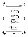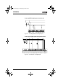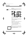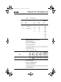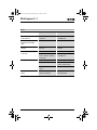
1
EZ500_700.book Page 1 Tuesday, May 3, 2005 5:15 PM EZ500/700 Series User Manual April 2005 Re-Order from OmegamationTM 1-888-55-66342 1-888-55-OMEGA omegamation.com MN05013003E For more information visit: www.EatonElectrical.com EZ500_700.book Page 2 Tuesday, May 3, 2005 5:15 PM EZ500_700.book Page I Tuesday, May 3, 2005 5:15 PM Warning! Dangerous electrical voltage! Before commencing the installation • Disconnect the power supply of the device. • Ensure that devices cannot be accidentally restarted. • Verify isolation from the supply. • Short circuit to earth. • Cover or enclose neighboring units that are live. • Follow the engineering instructions (AWA) of the device concerned. • Only suitably qualified personnel in accordance with EN 50110-1/-2 (VDE 0105 Part 100) may work on this device/system. • Before installation and before touching the device ensure that you are free of electrostatic charge. Eaton Safety instructions • The functional earth (FE) must be connected to the protective earth (PE) or to the potential equalization. The system installer is responsible for implementing this connection. • Connecting cables and signal lines should be installed so that inductive or capacitive MN05013003E interference does not impair the automation functions. • Install automation devices and related operating elements in such a way that they are well protected against unintentional operation. • Suitable safety hardware and software measures should be implemented for the I/O interface so that a line or wire breakage on the signal side does not result in undefined states in the automation devices. • Ensure a reliable electrical isolation of the low voltage for the 24 volt supply. Only use power supply units complying with IEC 60364-4-41 (VDE 0100 Part 410) or HD 384.4.41 S2. • Deviations of the mains voltage from the rated value must not exceed the tolerance limits given in the specifications, otherwise this may cause malfunction and dangerous operation. • Emergency stop devices complying with IEC/EN 60204-1 must be effective in all operating modes of the automation devices. Unlatching the emergency-stop devices must not cause restart. For more information visit: www.EatonElectrical.com I EZ500_700.book Page II Tuesday, May 3, 2005 5:15 PM • Devices that are designed for mounting in housings or control cabinets must only be operated and controlled after they have been installed with the housing closed. Desktop or portable units must only be operated and controlled in enclosed housings. • Wherever faults in the automation system may cause damage to persons or property, external measures must be implemented to ensure a safe operating state in the event of a fault or malfunction (for example, by means of separate limit switches, mechanical interlocks etc.). • Measures should be taken to ensure the proper restart of programs interrupted after a voltage dip or failure. This should not cause dangerous operating states even for a short time. If necessary, emergency-stop devices should be implemented. II MN05013004E For more information visit: www.EatonElectrical.com MN05013003E EZ500_700.book Page 1 Tuesday, May 3, 2005 5:15 PM Contents 1 MN05013003E About This Manual Device designation Writing conventions 9 9 10 EZ Target readership Proper use – Improper use Overview Modelse – Type reference EZ operation – Buttons – Moving through menus and choosing values – Selecting main and system menu – EZ Status display – Status display for local expansion – Advanced Status display – EZ LED display – Menu structure – Selecting or toggling between menu items – Cursor display – Setting values 11 11 11 11 12 15 17 18 18 18 19 20 20 21 21 22 27 27 28 For more information visit: www.EatonElectrical.com 1 EZ500_700.book Page 2 Tuesday, May 3, 2005 5:15 PM 2 3 2 Installation Mounting Connecting the expansion device Terminals – Tools – Cable cross-sections Connecting the power supply – Cable protection – Supplying AC units – Supplying DC units Connecting the inputs – Connecting EZ AC digital inputs – Connecting EZ DC digital inputs – Connecting EZ DC analog inputs – Connecting high-speed counters and frequency generators Connecting the outputs – Connecting relay outputs – Connecting transistor outputs Expanding inputs/outputs – Local expansion – Remote expansion Connecting bus systems 49 51 52 54 57 57 58 60 Commissioning Switching on Setting the menu language EZ operating modes Creating your first circuit diagram – Circuit diagram display – From the first contact to the output coil – Wiring – Testing the circuit diagram – Deleting the circuit diagram – Fast circuit diagram entry 61 61 62 63 64 66 67 68 69 71 71 For more information visit: www.EatonElectrical.com 29 29 32 33 33 33 33 33 34 35 37 37 42 44 MN05013003E EZ500_700.book Page 3 Tuesday, May 3, 2005 5:15 PM 4 MN05013003E Wiring with EZ Operation of EZ – Buttons for editing circuit diagrams and function relays – Operation – Relay, function relays – Saving and loading circuit diagrams Working with contacts and relays – Input and output contacts – Creating and modifying connections – Inserting and deleting a rung – Switching with the cursor buttons – Checking the circuit diagram – Coil functions Function relays – Example with function relay timer and counter relay Analog value comparator/threshold value switch – Circuit diagram display with analog value comparator – Parameter display in RUN mode – Resolution of the analog inputs – Function of the analog value comparator Counters – Function of the counter function relay High-speed counters, EZ-DA, EZ-DC – Frequency counters – High-speed counter Text display – Wiring a text display – Retention – Scaling – Function – Text entry – Character set – Entering a setpoint in a display For more information visit: www.EatonElectrical.com 73 73 73 74 77 80 80 81 84 86 87 88 89 95 96 102 103 105 105 106 114 118 122 122 128 134 135 135 136 136 137 137 138 3 EZ500_700.book Page 4 Tuesday, May 3, 2005 5:15 PM 7-day time switch – Parameter display and parameter set for 7-day time switch: – Changing time switch channel – Function of the 7-day time switch Operating hours counter – Value range of the operating hours counter – Accuracy of the operating hours counter – Function of the operating hours counter function block Timing relays – Parameter display and parameter set for a timing relay: – Retention – Timing relay modes – Time range – Function of the timing relay function block – Timing relay examples Jumps – Function – Power flow display Year time switch – Wiring of a year time switch – Parameter display and parameter set for the year time switch: – Changing time switch channel – Entry rules – Function of the year time switch Master reset – Operating modes – Function of the master reset function relay 4 For more information visit: www.EatonElectrical.com 140 140 141 142 145 146 146 146 150 150 151 152 152 155 163 166 166 167 169 169 170 171 171 173 176 177 177 MN05013003E EZ500_700.book Page 5 Tuesday, May 3, 2005 5:15 PM 5 MN05013003E Basic circuits – Negation (contact) – Negation (coil) – Maintained contact – Series circuit – Parallel circuit – Parallel circuit operating like a series connection of make contacts – Parallel circuit operating like a series connection of break contacts – Two-way circuit – Self-latching – Impulse relay – Cycle pulse on rising edge – Cycle pulse on falling edge Example circuits – Star-delta starting – 4x shift register – Running light – Stairwell lighting 182 182 183 184 184 185 186 186 188 192 194 EZ Settings Password protection – Password setup – Selecting the scope of the password – Activating the password – Unlocking EZ – Changing or deleting the password range Changing the menu language Changing parameters – Adjustable parameters for function relays Setting date, time and daylight saving time – Setting the time – Setting summer time start and end – Setting summer time start and end – Summer time start and end, setting the rule Activating debounce (input delay) – Activating debounce (input delay) – Deactivating debounce (input delay) 199 199 200 201 202 203 204 205 206 207 209 209 210 211 211 218 219 219 For more information visit: www.EatonElectrical.com 178 178 179 179 179 180 181 5 EZ500_700.book Page 6 Tuesday, May 3, 2005 5:15 PM Activating and deactivating the P buttons – Activating the P buttons – Function of the P buttons – Deactivating the P buttons Startup behavior – Setting the startup behavior – Behavior when the circuit diagram is deleted – Behavior during upload/download to card or PC – Possible faults – Card mode behavior Setting the cycle time Retention (non-volatile data storage) – Permissible markers and function relays – Setting retentive behavior – Deleting retentive actual values – Transferring retentive behavior – Changing the operating mode or the circuit diagram – Changing the startup behavior in the SYSTEM menu Displaying device information 6 For more information visit: www.EatonElectrical.com 220 220 220 221 221 221 222 222 223 223 225 226 226 226 228 228 229 229 230 MN05013003E EZ500_700.book Page 7 Tuesday, May 3, 2005 5:15 PM 6 7 MN05013003E Inside EZ EZ circuit diagram cycle – EZ operation and effects on circuit diagram creation Delay times for inputs and outputs – Delay times with EZ-DA and EZ-DC basic units – Delay time with EZ-AB, EZ-AC basic units – Delay times for the analog inputs of EZ-AB, EZ-DA and EZ-DC Monitoring of short-circuit/overload with EZ..-D.-T.. Expanding EZ700 – How is an expansion unit recognized – Transfer behavior – Function monitoring of expansion units Saving and loading circuit diagrams – EZ…-..-..X – Interface Memory card – Loading or saving circuit diagrams EZSoft Overview with stand-alone display/operating unit Device version What Happens If ...? Messages from the EZ system Possible situations when creating circuit diagrams Event For more information visit: www.EatonElectrical.com 231 231 232 234 234 236 237 238 239 240 240 241 242 242 242 244 245 248 249 250 251 251 252 254 7 EZ500_700.book Page 8 Tuesday, May 3, 2005 5:15 PM 8 Appendix Dimensions Technical Data – General – Special approvals – Power supply – Inputs – Relay outputs – Transistor outputs List of the function relays – Usable contacts – Available function relays – Names of relays – Names of function relay – Name of function block inputs (constants, operands) – Memory card attributes 255 255 258 258 260 261 262 268 270 273 273 274 275 275 Glossary 277 Index 281 For more information visit: www.EatonElectrical.com 276 276 MN05013003E EZ500_700.book Page 9 Tuesday, May 3, 2005 5:15 PM About This Manual This manual describes the installation, commissioning and programming (circuit diagram generation) of the EZ500 and EZ700 control relay. Specialist electrical training is needed for commissioning and creating circuit diagrams. When active components such as motors or pressure cylinders are controlled, parts of the system can be damaged and persons put at risk if the device is connected or programmed incorrectly. Device designation This manual uses the following abbreviated designations for different EZ models: EZ512-..-..., EZ7..-..-... Type designation of the control relay, the dots represent placeholders for all characters used. EZ500 for EZ512-AB-..., EZ512-AC-..., EZ512-DA-... and EZ512-DC-... EZ700 for EZ719-AB-..., EZ719-AC-..., EZ719-DA-..., EZ719-DC-... and EZ721-DC-... EZ-AB for EZ512-AB-... EZ719-AB-... EZ-AC for EZ512-AC-... EZ618-AC-RE and EZ719-AC-... EZ-DA for EZ512-DA-... EZ719-DA-... EZ-DC for EZ512-DC-... EZ6..-DC-..., EZ719-DC-... and EZ721-DC-... MN05013003E For more information visit: www.EatonElectrical.com 9 EZ500_700.book Page 10 Tuesday, May 3, 2005 5:15 PM About This Manual EZ-E for EZ2.._RE, EZ618-AC-RE, EZ618-DC-RE and EZ620-DC-TE EZSoft for EZSoftBasic and EZSoft Writing conventions Symbols used in this manual have the following meanings: X indicates actions to be taken. Attention! Warns of a hazardous situation that could result in damage to the product or components. Caution! Warns of the possibility of serious damage and slight injury. Warning! Warns of the possibility of a hazardous situation that could result in major damage and serious or fatal injury or even death. J Indicates interesting tips and additional information For greater clarity, the name of the current chapter is shown in the header of the left-hand page and the name of the current section in the header of the right-hand page. Pages at the start of a chapter and empty pages at the end of a chapter are exceptions. 10 MN05013003E For more information visit: www.EatonElectrical.com MN05013003E EZ500_700.book Page 11 Tuesday, May 3, 2005 5:15 PM 1 Target readership EZ EZ must only be installed and connected up by trained electricians or other persons who are familiar with the installation of electrical equipment. Specialist electrical training is needed for commissioning and creating circuit diagrams. When active components such as motors or pressure cylinders are controlled, parts of the system can be damaged and persons put at risk if EZ is connected or programmed incorrectly. Proper use EZ is a programmable switching and control device and is used as a replacement for relay and contactor control circuits. EZ may only be operated when it has been correctly and properly installed. • EZ is designed to be installed in an enclosure, switch cabinet or service distribution board. Both the power feed and the signal terminals must be laid and covered so as to prevent accidental contact. • The installation must comply with regulations for electromagnetic compatibility (EMC). • The starting up of EZ should not cause any hazards arising from controlled devices, such as unexpected motor startups or power ups. Improper use EZ should not be used as a substitute for safety-related controls such as burner or crane controls, emergency-stop or two-hand safety controls. MN05013003E For more information visit: www.EatonElectrical.com 11 EZ500_700.book Page 12 Tuesday, May 3, 2005 5:15 PM EZ Overview 2 3 4 1 2 5 10 POW 6 BUS POWER COM-ERR 7 ADR ERR 8 MS NS Figure 1: 12 9 EZ basic units and expansion devices For more information visit: www.EatonElectrical.com MN05013003E EZ500_700.book Page 13 Tuesday, May 3, 2005 5:15 PM Overview Legend for figure 1: EZ500 basic unit EZ700 I/O expansion EZ202-RE output expansion EZ200-EZ coupling device EZ-LINK-DS data connector EZ204-DP PROFIBUS-DP slave gateway EZ205-ASI AS-Interface slave gateway EZ221-CO CANopen gateway EZ222-DN DeviceNet gateway EZ700 basic unit EZ is an electronic control relay with logic functions, timer, counter and time switch functions. It is also a control and input device in one that can perform many different tasks in domestic applications as well as in machine building and plant construction. Circuit diagrams are connected up using ladder diagrams, and each element is entered directly via the EZ display. For example, you can: • • • • • • • • • • • • • MN05013003E Connect make and break contacts in series and in parallel Connect output relays and markers, Use outputs as relays, impulse relays or latching relays Use multi-function timing relays with different functions Use up and down counters, Count high-speed counter pulses Measure frequencies Process analog inputs, EZ-AB, EZ-DA, EZ-DC, (EZ512..: two analog inputs, EZ700: four analog inputs) Display any texts with variables, enter setpoints Use year time switches, 7-day time switches, EZ…-..-.C(X), Count operating hours (four retentive operating hours counters integrated) Track the flow of current in the circuit diagram Load, save and password-protect circuit diagrams For more information visit: www.EatonElectrical.com 13 EZ500_700.book Page 14 Tuesday, May 3, 2005 5:15 PM EZ If you prefer to wire up EZ from a PC, then use EZSoft. EZSoft allows you to create and test your circuit diagram on the PC. EZSoft is also used to print out your circuit diagram in DIN, ANSI or EZ format. 14 For more information visit: www.EatonElectrical.com MN05013003E EZ500_700.book Page 15 Tuesday, May 3, 2005 5:15 PM Overview Models EZ basic units at a glance 햲 DEL 햳 ALT 햸 햴 햵 ESC DEL OK ALT 햶 ESC Figure 2: MN05013003E OK 햷 Models Power supply Inputs Status LED Buttons Interface socket for memory card or PC connection Outputs LCD display For more information visit: www.EatonElectrical.com 15 EZ500_700.book Page 16 Tuesday, May 3, 2005 5:15 PM EZ EZ basic units with stand-alone EZD-80.., EZD-CP4-500 HMI unit 1 2 3 4 3 Figure 3: 16 Overview with stand-alone HMI unit EZ500 basic units EZ700 basic units EZD device Power supply/communication module with EZD-CP4-500 interface cable For more information visit: www.EatonElectrical.com MN05013003E EZ500_700.book Page 17 Tuesday, May 3, 2005 5:15 PM Overview Type reference EZ x xx -xx-x x x LCD display: X = No display Time switch: C = Available; E = Expansion Output type: R = Relay (max. 8 A) T = Transistor (0.5 A, parallel connection possible up to 2 A) Supply voltage, device and inputs AB = 24 V AC (2, (4) inputs, also usable as 0 to 10 V analog inputs) AC = 100, 120, 230, 240 V AC DC = 24 V DC (2 (4) inputs, also usable as 0 to 10 V analog inputs) DA = 12 V DC (2 (4) inputs, also usable as 0 to 10 V analog inputs) Number of inputs/outputs (+ expansion) 12 = 8 I/4 O 18 = 12 I/6 O 19 = 12 I/6 O + expansion 20 = 12 I/8 O 21 = 12 I/8 O + expansion Rating class (RC) and space unit (SU) 2 = 35.5 mm (SU) 5 = 71.5 mm (4 SU), RC = 4 or 5 6, 7= 107.5 mm (6 SU), RC = 6 or 7 EZ control relay MN05013003E For more information visit: www.EatonElectrical.com 17 EZ500_700.book Page 18 Tuesday, May 3, 2005 5:15 PM EZ EZ operation Buttons ALT DEL DEL: Delete object in circuit diagram ALT: Special functions in circuit diagram, Status display Cursor buttons ú í ÍÚ: OK ESC Move cursor Select menu items Set contact numbers, contacts and values OK: Next menu level, Save your entry ESC: Previous menu level, Cancel Moving through menus and choosing values Show System menu and Go to next menu level Select menu item Store your entry Return to last menu level Cancel your entry since the last OK ÍÚ ú í Change menu item Change value Change position P button function (if enabled): ú í 18 Input P1 Input P3 Í Input P2 Ú Input P4 For more information visit: www.EatonElectrical.com MN05013003E EZ500_700.book Page 19 Tuesday, May 3, 2005 5:15 PM Overview Selecting main and system menu Status display EZ500: 8 inputs, 4 outputs I .2..5..... P1.2 MO 02:00 RS ..34 . RUN MO .2 6.. Current selection flashes in the EZ menu Clock menu on devices with clock and No password PROGRAM... STOPå RUN PARAMETER INFO... SET CLOCK SECURITY... SYSTEM... LANGUAGE... 1st menu level 1st menu level Main menu EZ500 or EZ700 System menu SECURITY... SYSTEM... LANGUAGE... CONFIGURATOR The CONFIGURATOR menu appears if a configurable expansion module is connected such as EZ204-DP (PROFIBUS-DP bus gateway) MN05013003E For more information visit: www.EatonElectrical.com 19 EZ500_700.book Page 20 Tuesday, May 3, 2005 5:15 PM EZ Toggling between weekday, time display and date display (only on devices with clock) .2..5....... PMO 11:50 ..34 RUN .2..5....... P01.04.2004 ..34 RUN EZ Status display .2..5....... PMO 11:50 Q ..34..STOP Inputs Weekday/Time Outputs 1.......9... RS .2..5...... P01.04.2002 Q ..34..STOP EZ500: input 1 to 8, EZ700: input 1 to 12 AC P- MO 10:42 1.....7. RUN On: 1, 2, 3, 4 /Off:… or Weekday/Date RUN/STOP mode EZ500: output 1 to 4, EZ700: output 1 to 6 or 8 Status display for local expansion Inputs Expansion Weekday/Time Outputs 1.......9... RS AC P- MO 10:42 1.....7. RUN or Weekday/Date On: 1, 2, 3, 4/Off:… RS = Expansion functioning correctly 20 For more information visit: www.EatonElectrical.com MN05013003E EZ500_700.book Page 21 Tuesday, May 3, 2005 5:15 PM Overview Advanced Status display 12...6.89... Retention/Debounce RE I AC P- 17.03.04 ST 123.5.78 RUN RE I AC DC GW ST AC expansion ok/P buttons Startup behavior : : : : : Retention switched on Debounce switched on AC expansion functioning correctly DC expansion functioning correctly Bus coupling module detected GW flashes: Only EZ200-EZ detected. I/O expansion not detected. 17.03.04 Display of actual device date : When the power supply is switched on, EZ switches to STOP mode EZ LED display EZ512-..-..X, EZ700 and EZ-E feature an LED on the front indicating the status of the power supply as well as whether RUN or STOP mode is active (J figure 2, page 15). MN05013003E LED OFF No power supply LED continuously lit Power supply present, STOP mode LED flashing Power supply present, RUN mode For more information visit: www.EatonElectrical.com 21 EZ500_700.book Page 22 Tuesday, May 3, 2005 5:15 PM EZ Menu structure Main menu without password protection XYou access the main menu by pressing OK. STOP: Circuit diagram display Main menu PROGRAM....Æ STOP å RUN PARAMETER INFO... æ SET CLOCK.. PROGRAM... DELETE PROG CARD The arrows indicate that there are more than four menus. Circuit diagram Parameter display SAVE CANCEL PROGRAM... DELETE PROG CARD... PROGRAM... DELETE PROG CARD... DELETE ? DEVICE-CARD CARD-DEVICE DELETE CARD DEVICE-CARD CARD-DEVICE DELETE CARD DEVICE-CARDE CARD-DEVICE DELETE CARD 22 Parameters For more information visit: www.EatonElectrical.com REPLACE ? REPLACE ? DELETE ? MN05013003E EZ500_700.book Page 23 Tuesday, May 3, 2005 5:15 PM Overview Main menu PROGRAM....Æ STOP RUN å PARAMETER INFO... æ SET CLOCK.. PROGRAM....Æ STOP RUN å PARAMETER... INFO... æ SET CLOCK.. PROGRAM....Æ STOP RUN å PARAMETER... INFO... æ SET CLOCK.. PROGRAM... STOP RUN Æ PARAMETER INFO... SET CLOCK.æ MN05013003E Parameter display T1 X T2 Ü C1 N O1 S + M:S + + + T1 X S + S1 10.000 S2 +0 T: Information display of the device DC TC LCD OS: 1.00.027 CRC: 02752 Display for date and time setting SET CLOCK.. SUMMER TIME.. HH:MM DD.MM YEAR --:---.-____ For more information visit: www.EatonElectrical.com HH:MM DD.MM YEAR 14:23 17.03 2004 23 EZ500_700.book Page 24 Tuesday, May 3, 2005 5:15 PM EZ Main menu Only one selection is possible. PROGRAM... STOP RUN Æ PARAMETER... INFO... SET CLOCK.æ SET CLOCK.. SUMMER TIME. SET CLOCK.. SUMMER TIME. SET CLOCK.. SUMMER TIME. SET CLOCK.. SUMMER TIME. 24 NONE RULE... EU GB US åÆ NONE RULE... EU GB US Æ æ æ SUMMER START SUMMER END AM WD: --Æ --DD.MM:00.00æ HH:MM:00:00 DIFF: 0:00 NONE RULE... EU GB US Æ å NONE RULE... EU GB US Æ å æ SUMMER START SUMMER END SUMMER START SUMMER END æ For more information visit: www.EatonElectrical.com AM WD: --Æ --DD.MM:00.00æ HH:MM:00:00 DIFF: 0:00 MN05013003E EZ500_700.book Page 25 Tuesday, May 3, 2005 5:15 PM Overview Main menu with password protection Main menu Unlocking EZ Password entry PASSWORD.. Æ STOP RUN å PARAMETER... INFO... æ SET CLOCK.. DELETE ALL Password Example: Password only on program Four wrong entries (if enabled) Status display PASSWORD... STOP RUN å Correct entry EZ System menu The System menu is accessed by simultaneously pressing DEL and ALT. Password setup System menu Password entry SECURITY... SYSTEM... LANGUAGE... CONFIGURATOR Change/ delete password MN05013003E PASSWORD... RANGE... ENTER PASSW: XXXX CHANGE PW ACTIVATE PW ACTIVATE PW CHANGE PW ENTER PASSW: XXXX CHANGE PW ACTIVATE PW PASSWORD... RANGE... PROGRAM å Æ PARAMETER TIME MODE æ INTERFACE DEL PROG PROGRAM å Æ PARAMETER å TIME å MODE æ INTERFACE å DEL PROG å For more information visit: www.EatonElectrical.com 25 EZ500_700.book Page 26 Tuesday, May 3, 2005 5:15 PM EZ System menu SECURITY... SYSTEM... LANGUAGE... CONFIGURATOR DEBOUNCE å P-BUTTONS RUN MODE å CARD MODE SECURITY... SYSTEM... LANGUAGE... CONFIGURATOR ENGLISH Æ DEUTSCH å FRANCAIS ESPANOL æ ITALIANO PORTUGUES NEDERLANDS SVENSKA POLSKI TURKCE CESKY MAGYAR SECURITY... SYSTEM... LANGUAGE... CONFIGURATOR 26 Only one selection is possible. The further menus depend on the connected expansion device For more information visit: www.EatonElectrical.com MN05013003E EZ500_700.book Page 27 Tuesday, May 3, 2005 5:15 PM Overview Selecting or toggling between menu items Cursor Í Ú PROGRAM... STOP PARAMETER INFO Select or toggle Cursor display MN05013003E HH:MM DD.MM YEAR '4:23 17.03 2004 HH:MM DD.MM YEAR 14:23 17.03 2004 The cursor flashes. Full cursor Ê/: • Move cursor with ú í, • in circuit diagram also with Í Ú Value M/ M • Change position with ú í • Change values with Í Ú Flashing values/menus are shown in gray in this manual. For more information visit: www.EatonElectrical.com 27 EZ500_700.book Page 28 Tuesday, May 3, 2005 5:15 PM EZ Setting values HH:MM DD.MM YEAR 14:23 17.03 2004 Values Digits Current value at the position (can be changed, Cursor = 3) 28 Select value Í Ú Select digit ú í Change value at digit ÍÚ Store entries Retain previous value For more information visit: www.EatonElectrical.com MN05013003E EZ500_700.book Page 29 Tuesday, May 3, 2005 5:15 PM 2 Installation EZ must only be installed and wired up by trained electricians or other persons familiar with the installation of electrical equipment. Danger of electric shock Never carry out electrical work on the device while the power supply is switched on. Always follow the safety rules: • • • • Switch off and isolate Secure against reclosing Ensure that the device is no longer live Cover adjacent live parts EZ is installed in the following order: • • • • • Mounting If necessary connect devices together Mounting Wiring up the inputs Wiring up the outputs Connecting the power supply Install EZ in a control cabinet, service distribution board or in an enclosure so that the power feed and terminal connections cannot be touched accidentally during operation. Clip EZ onto a DIN EN 50022 top-hat rail or fix EZ in place using fixing brackets. EZ can be mounted vertically or horizontally. J MN05013003E When using EZ with expansion units, connect the expansion concerned before mounting (J page 32). For more information visit: www.EatonElectrical.com 29 EZ500_700.book Page 30 Tuesday, May 3, 2005 5:15 PM Installation 30 For ease of wiring, leave a gap of at least 30 mm between EZ terminals and the wall or adjacent devices. 30 30 30 Figure 1: 1 Clearances to EZ Mounting on top-hat rail XHook EZ to the top edge of the top-hat rail and hinge into place while pressing down slightly. Press the device lightly downwards and against the top-hat rail until it snaps over the lower edge of the top-hat rail. EZ will clip into place and will be secured by the built-in spring mechanism. XCheck that the device is seated firmly. EZ is mounted vertically on a top-hat rail in the same way. 2 30 For more information visit: www.EatonElectrical.com MN05013003E EZ500_700.book Page 31 Tuesday, May 3, 2005 5:15 PM Mounting Using a mounting plate Mounting on a mounting plate requires the use of fixing brackets which are fixed to the back of EZ. The fixing brackets are available as an accessory. EZ700: Fasten each device with at least three fixing brackets. EZ200-EZ: EZ500: EZ700: Figure 2: MN05013003E Using a mounting plate For more information visit: www.EatonElectrical.com 31 EZ500_700.book Page 32 Tuesday, May 3, 2005 5:15 PM Installation Connecting the expansion device 1 2 4 3 Figure 3: 32 Connecting expansion units For more information visit: www.EatonElectrical.com MN05013003E EZ500_700.book Page 33 Tuesday, May 3, 2005 5:15 PM Terminals XOpen the EZ-LINK connections on the side of both EZ devices. XFit the EZ-LINK data connector EZ-LINK-DS in the opening provided on the expansion device. XPlug the devices together. XProceed in the reverse order to dismantle the device. Terminals Tools Slot-head screwdriver, width 3.5 mm, tightening torque 0.6 Nm. Cable cross-sections • Solid: 0.2 to 4 mm2 • Flexible with ferrule: 0.2 to 2.5 mm2 Connecting the power supply J The required connection data for device types, EZ-AB with 24 V AC, EZ-AC with standard voltages of 100 V AC, EZDA with 12 V DC and EZ-DC with 24 V DC are provided in the section “Technical Data”, page 258. The EZ500 and EZ700 basic units run a system test for two seconds after the power supply has been switched on. Either RUN or STOP mode will be activated after these two seconds, depending on the default setting. Cable protection Connect on EZ cable protection (F1) rated for at least 1 A (slow). MN05013003E For more information visit: www.EatonElectrical.com 33 EZ500_700.book Page 34 Tuesday, May 3, 2005 5:15 PM Installation Supplying AC units Supplying AC basic units EZ…-AB-RC(RCX), EZ…-AC-R(RC, RCX) L N F1 L Figure 4: N N Power supply on the AC basic units Supplying AC expansion units EZ…-AC-.E L N F1 E+ E- Figure 5: 34 R1 ... R12 L N N Power supply on the AC expansion units For more information visit: www.EatonElectrical.com MN05013003E EZ500_700.book Page 35 Tuesday, May 3, 2005 5:15 PM Connecting the power supply Applies to EZ-AC devices with a power supply greater than 24 V AC: • The voltage terminals for phase L and neutral conductor N have been reversed. • This enables the EZ interface (for memory card or PC connection) to have the full connection voltage of the phase conductor (100 to 240 V AC). • There is a danger of electric shock if the connection at the EZ interface is not properly connected or if conductive objects are inserted into the socket. Attention! A short current surge will be produced when switching on for the first time. Do not switch on EZ by means of reed contacts since these may burn or melt. Supplying DC units Supplying DC basic units EZ…-DA-RC(X), EZ…-DC-R(RC,RCX) L01⫹ L01⫺ F1 +...V 0 V 0V DC : +24 V DA : +12 V Figure 6: MN05013003E Power supply on the DC basic units For more information visit: www.EatonElectrical.com 35 EZ500_700.book Page 36 Tuesday, May 3, 2005 5:15 PM Installation Supplying DC expansion units EZ…-DC-.E L01+ L01F1 E+ E- Figure 7: J R1 ... R12 24V 0V 0V 24 V Power supply on the DC expansion units EZ-DC and EZ-DA are protected against reverse polarity. To ensure that EZ works correctly, ensure that the polarity of each terminal is correct. Cable protection Connect on EZ a cable protection (F1) rated for at least 1 A (slow). J 36 When EZ is switched on for the first time, its power supply circuit behaves like a capacitor. Use an appropriate device for switching on the power supply and do not use any reed relay contacts or proximity switches. For more information visit: www.EatonElectrical.com MN05013003E EZ500_700.book Page 37 Tuesday, May 3, 2005 5:15 PM Connecting the inputs Connecting the inputs EZ inputs switch electronically. Once you have connected a contact via an input terminal, you can reuse it as a contact in your EZ circuit diagram as often as you like. L +24 V S1 N 0V I1 I1 Figure 8: i1 Connecting the inputs Connect to the EZ input terminals contacts such as pushbuttons, switches, relay or contactor contacts, proximity switches (three-wire). Connecting EZ AC digital inputs Caution! Connect the inputs for AC devices in compliance with the safety regulations of the VDE, IEC, UL and CSA. Use the same phase conductor for the input power feed, otherwise EZ will not detect the switching level and may be damaged or destroyed by overvoltage. MN05013003E For more information visit: www.EatonElectrical.com 37 EZ500_700.book Page 38 Tuesday, May 3, 2005 5:15 PM Installation Connecting EZ AC digital inputs on the basic unit L N F1 L Figure 9: N N l1 I2 I7 Connecting EZ-AC and EZ-AB digital inputs Connecting AC digital inputs on the expansion device L N F1 E+ E- Figure 10: 38 R1 R2 R3 R4 R5 R6 R7 R8 R9 R10 R11 R12 L N N Connecting EZ...-AC-E digital inputs For more information visit: www.EatonElectrical.com MN05013003E EZ500_700.book Page 39 Tuesday, May 3, 2005 5:15 PM Connecting the inputs Table 1: EZ-AB input signal values Input signal voltage range Input current OFF signal ON signal 0 to 6 V AC 14 to 26.4 V AC 4 mA at 24 V AC EZ500/ EZ700 I1 to I6 I7, I8 greater than 7 V AC or greater than 9.5 V DC 2 mA with 24 V AC and 24 V DC EZ700 I9, I10 14 to 26.4 V AC 4 mA at 24 V AC I11, I12 greater than 7 V AC or greater than 9.5 V DC 2 mA with 24 V AC and 24 V DC Table 2: EZ-AC input signals Input signal voltage range EZ500/ EZ700 I1 to I6 OFF signal ON signal 0 to 40 V 79 to 264 V Input current 0.5 mA at 230 V AC/0.25 mA at 115 V AC I7, I8 6 mA at 230 V AC/4 mA at 115 V EZ700 I9 to I12 EZ600 R1 to R12 0.5 mA at 230 V AC/0.25 mA at 115 V AC Cable lengths Severe interference can cause a “1” signal on the inputs without a proper signal being applied. Observe therefore the following maximum cable lengths: I1 to I6 40 m without additional circuit I7, I8 100 m without additional circuit I9 to I12 40 m without additional circuit R1 to R12 MN05013003E For more information visit: www.EatonElectrical.com 39 EZ500_700.book Page 40 Tuesday, May 3, 2005 5:15 PM Installation For longer lengths connect in series a diode (e.g. 1N4007) for 1 A, min. 1000 V reverse voltage, to the EZ input. Ensure that the diode is pointing towards the input as shown in the circuit diagram, otherwise EZ will not detect the 1 state. L N F1 L Figure 11: N N I1 AC input with suppression diode for EZ-AC and EZ-AB EZ-AC: Inputs I7 and I8 have a higher input current on the EZ-AC. Neon bulbs with a maximum residual current of 2 mA/1 mA at 230 V/115 V can be connected to I7 and I8. J Always use neon bulbs that are operated with a separate N connection. Caution! Do not use reed relay contacts at I7, I8. These may burn or melt due to the high inrush current of I7, I8. Two-wire proximity switches have a residual current with the “0” state. If this residual current is too high, the EZ input may only detect a “1” signal. Therefore, use inputs I7 and I8. An additional input circuit is required if more inputs are used. 40 For more information visit: www.EatonElectrical.com MN05013003E EZ500_700.book Page 41 Tuesday, May 3, 2005 5:15 PM Connecting the inputs Increasing the input current The following input circuit can be used in order to prevent interference and also when using two-wire proximity switches: L N F1 100 nF/275 V h L Figure 12: J N N I1 Increasing the input current When using a 100 nF capacitor the drop-off time of the input increases by 80 (66.6) ms at 50 (60) Hz. A resistor can be connected in series with the circuit shown in order to restrict the inrush current. L N F1 1 kO L Figure 13: MN05013003E N N 100 nF/275 V h I1 Limitation of the input current with a resistor For more information visit: www.EatonElectrical.com 41 EZ500_700.book Page 42 Tuesday, May 3, 2005 5:15 PM Installation Complete devices for increasing the input current are available under the type reference EZ256-HCI. L N F1 L N N Figure 14: J 1 I1 N EZ with EZ256-HCI The increased capacitance increases the drop-off time by approx. 40 ms. Connecting EZ DC digital inputs Use input terminals I1 to I12, R1 to R12 to connect pushbutton actuators, switches or 3 or 4-wire proximity switches. Given the high residual current, do not use 2-wire proximity switches. 42 For more information visit: www.EatonElectrical.com MN05013003E EZ500_700.book Page 43 Tuesday, May 3, 2005 5:15 PM Connecting the inputs Connecting DC digital inputs on the basic unit L01⫹ L01⫺ F1 +...V 0V l1 I2 I7 DC : +24 V DA : +12 V Figure 15: Connecting EZ-DC, EZ-DA digital inputs Connecting DC digital inputs on the expansion device +24 V 0V F1 E+ E- R1 R2 R3 R4 R5 R6 R7 R8 R9 R10 R11 R12 +24V 0V 0V Input 24 V 24 V EZ…-DC-.D Figure 16: MN05013003E Connecting EZ...-DC-E digital inputs For more information visit: www.EatonElectrical.com 43 EZ500_700.book Page 44 Tuesday, May 3, 2005 5:15 PM Installation Table 3: EZ-DC input signals Input signal voltage range Input current OFF signal ON signal 0 to 5 V 15 to 28.8 V 3.3 mA at 24 V DC EZ500/ EZ700 I1 to I6 I7, I8 greater than 8 V DC 2.2 mA at 24 V EZ700 I9, I10 15 to 28.8 V 3.3 mA at 24 V DC I11, I12 greater than 8 V DC 2.2 mA at 24 V R1 to R12 15 to 28.8 V 3.3 mA at 24 V DC EZ600 Table 4: EZ-DA input signals Input signal voltage range OFF signal ON signal 0 to 4 V DC 8 to 15.6 V DC Input current EZ500/ EZ700 I1 to I6 3.3 mA at 12 V I7, I8 1.1 mA at 12 V EZ700 I9, I10 3.3 mA at 12 V I11, I12 1.1 mA at 12 V Connecting EZ DC analog inputs The EZ-AB, EZ-DA and EZ-DC basic units are provided with analog inputs. Inputs I7 and I8, and if present I11 and I12, can be used to connect analog voltages ranging from 0 V to 10 V. A simple additional circuit also allows the analog evaluation of currents from 0 to 20 mA. The analog input signals are converted to 10-bit digital signals. The following applies: • 0 V DC corresponds to a digital 0. • 5 V DC corresponds to a digital value of 512. • 10 V DC corresponds to a digital value of 1023. 44 For more information visit: www.EatonElectrical.com MN05013003E EZ500_700.book Page 45 Tuesday, May 3, 2005 5:15 PM Connecting the inputs Caution! Analog signals are more sensitive to interference than digital signals. Consequently, greater care must be taken when laying and connecting the signal lines. Incorrect switching states may occur if they are not connected correctly. Safety measures with analog signals XUse shielded twisted pair cables to prevent interference with the analog signals. XFor short cable lengths, ground the shield at both ends using a large contact area. If the cable length exceeds 30 m or so, grounding at both ends can result in equalization currents between the two grounding points and thus in the interference of analog signals. In this case, only ground the cable at one end. XDo not lay signal lines parallel to power cables. XConnect inductive loads to be switched via the EZ outputs to a separate power feed, or use a suppressor circuit for motors and valves. If loads such as motors, solenoid valves or contactors are operated with EZ via the same power feed, switching may result in interference on the analog input signals. The following four circuits contain examples of applications for analog value processing. Caution! Ensure that the reference potential is connected. Connect the 0 V of the power supply unit for the different setpoint potentiometers and sensors shown in the examples to the 0 V and neutral conductor terminal (EZ-AB) of the EZ power feed. Otherwise incorrect switching states may occur if they are not connected correctly. MN05013003E For more information visit: www.EatonElectrical.com 45 EZ500_700.book Page 46 Tuesday, May 3, 2005 5:15 PM Installation Power supply of EZ-AB devices and analog inputs With EZ-AB devices that process analog signals, the device must be fed via a transformer so that the device is isolated from the mains supply. The neutral conductor and the reference potential of the DC power feed of analog sensors must be electrically connected. J Ensure that the common reference potential is grounded or monitored by a ground fault monitoring device. Observe the requirements of the relevant regulations. L1 N ~ 0V +12 V L01h F1 N01 h L Figure 17: 46 N N I1 I7 I8 EZ-AB analog input, connection of reference potentials For more information visit: www.EatonElectrical.com MN05013003E EZ500_700.book Page 47 Tuesday, May 3, 2005 5:15 PM Connecting the inputs Analog setpoint potentiometer, EZ-AB, EZ-DA, EZ-DC ~ F1 0V +...V L Figure 18: 0V N +12 V I7 0V N Analog setpoint potentiometer with own power feed Use a potentiometer with a resistance of 0.25 W. 1 kΩ, e.g. 1 kΩ, EZ-DC analog setpoint potentiometer L01⫹ L01⫺ 1.3 kO/0.25 W F1 1 kO/0.25 W +...V 0 V 0V I7 DC : +24 V DA : +12 V Figure 19: MN05013003E Analog setpoint potentiometer with 24 V DC power feed For more information visit: www.EatonElectrical.com 47 EZ500_700.book Page 48 Tuesday, May 3, 2005 5:15 PM Installation Brightness sensor, EZ-AB, EZ-DA, EZ-DC ~ 12 V 0...10 V F1 0V 0V +...V L 0V N Figure 20: +12 V I7 0V N Connection of a brightness sensor, analog input Temperature sensor, EZ-DA, EZ-DC +24 V –0 V Out 0...10 V F1 +...V L Figure 21: 48 0V N 0V N –35...55 ˚C I7 Connection of the temperature sensor, analog input For more information visit: www.EatonElectrical.com MN05013003E EZ500_700.book Page 49 Tuesday, May 3, 2005 5:15 PM Connecting the inputs 20 mA sensor 4 to 20 mA (0 to 20 mA) sensors can be connected easily without any problem using an external 500 Ω resistor. L01⫹ L01⫺ 햲 F1 4...20 mA 500 +...V 0V 0V I7 DC : +24 V DA : +12 V Figure 22: Connection 0 (4) to 20 mA sensor output, analog input Analog sensor The following values apply: • 4 mA = 1.9 V • 10 mA = 4.8 V • 20 mA = 9.5 V (Based on U = R × I = 478 Ω × 10 mA ~ 4.8 V). Connecting high-speed counters and frequency generators High-speed counter signals and frequencies on the EZ-DA and EZ-DC can be counted accurately on inputs I1 to I4 independently of the cycle time. These inputs are permanently assigned to counters. The following applies: • I1 = C13 high-speed up/down counter • I2 = C14 high-speed up/down counter MN05013003E For more information visit: www.EatonElectrical.com 49 EZ500_700.book Page 50 Tuesday, May 3, 2005 5:15 PM Installation • I3 = C15 frequency counter • I4 = C16 frequency counter Pulse shape of count signals: EZ processes square wave signals. Mark-to-space ratio of count signals: We recommend a mark-to-space ratio of 1:1. If this is not the case: The minimum pulse or pause duration is 0.5 ms. tmin = 0.5 × (1/fmax) tmin = minimum time of the pulse or pause duration fmax = maximum count frequency (1 kHz) L01 + L01 – L02 + F1 ...V 0V 0V I1 I2 I3 I4 I5 I6 24 V H Figure 23: 50 Connecting high-speed counters and frequency generators For more information visit: www.EatonElectrical.com MN05013003E EZ500_700.book Page 51 Tuesday, May 3, 2005 5:15 PM Connecting the outputs J Inputs that are used as high-speed counter inputs should not be used in the circuit diagram as contacts. If the counter frequency is high: Not all the signals of the high-speed counter can be monitored for processing in the circuit diagram. EZ will only process a randomly logged state. Connecting the outputs The Q outputs function inside EZ as isolated contacts. Q1 1 Figure 24: 2 Output Q The associated relay coils are controlled in the EZ circuit diagram via the following outputs. • Q1 to Q4 and Q1 to Q8 (Q6), basic units • S1 to S8 (S6), expansion devices You can use the signal states of the outputs as make or break contacts in the EZ circuit diagram to provide additional switching conditions. The relay or transistor outputs are used to switch loads such as fluorescent tubes, filament bulbs, contactors, relays or motors. Check the technical thresholds and data of the outputs before installation (J section “Technical Data”, page 258). MN05013003E For more information visit: www.EatonElectrical.com 51 EZ500_700.book Page 52 Tuesday, May 3, 2005 5:15 PM Installation Connecting relay outputs EZ512-..-R.. 1 2 1 Q1 1 2 2 Q3 Q2 1 2 L R Q4 24 V H 8 A 115 V h 8 A 230 V h 8 A 10 000 000 2A 2A 2A 1000 W 0 V H, N 10 x 58 W 25 000 F 8 A/B 16 L1, L2, L3 (115/230 V h) + 24 V H Figure 25: EZ512-..-R.. relay outputs EZ7..-..-R.. and 1 2 Q1 1 2 Q2 1 2 Q3 1 2 Q4 1 2 Q5 EZ202-RE 1 2 1 Q6 S1 10 000 000 1 2 S2 10 000 000 0 V H, N 0 V H, N F 8 A/B 16 F 8 A/B 16 L1, L2, L3 (115/230 V h) + 24 V H L1, L2, L3 (115/230 V h) + 24 V H Figure 26: 52 2 EZ7..-..-R.. relay outputs and EZ202-RE For more information visit: www.EatonElectrical.com MN05013003E EZ500_700.book Page 53 Tuesday, May 3, 2005 5:15 PM Connecting the outputs EZ618-..-RE 1 2 S1 1 2 S2 1 2 S3 1 2 1 2 S4 S5 1 2 S6 10 000 000 R 24 V H 8 A 115 V h 8 A 230 V h 8 A 2A 2A 2A 1000 W 0 V H, N 10 x 58 W 25 000 F 8 A/B 16 L1, L2, L3 (115/230 V h) + 24 V H Figure 27: EZ618-..-RE.. relay outputs Unlike the inputs, the outputs can be connected to different phases. Warning! Do not exceed the maximum voltage of 250 V AC on a relay contact. If the voltage exceeds this threshold, flashover may occur at the contact, resulting in damage to the device or a connected load. MN05013003E For more information visit: www.EatonElectrical.com 53 EZ500_700.book Page 54 Tuesday, May 3, 2005 5:15 PM Installation Connecting transistor outputs EZ512-..-T.. +24 VQ 0 VQ Q1 Q2 Q3 Q4 F10 A 0VH f 2.5 A + 24 V H 20.4 – 28.8 V H Figure 28: 24 V R L 0.5 A 0.5 A 5 W/24 V EZ512-..-T.. transistor outputs EZ7..-..-T.. +24 VQ 0 VQ Q1 Q2 Q3 Q4 Q5 Q6 Q7 Q8 F10 A 0VH R f 2.5 A + 24 V H (20.4 – 28.8 V H) 24 V H 0.5 A 0.5 A 5 W/24 V Figure 29: 54 EZ7..-..-T.. transistor outputs For more information visit: www.EatonElectrical.com MN05013003E EZ500_700.book Page 55 Tuesday, May 3, 2005 5:15 PM Connecting the outputs EZ620-..-TE S1 S2 S3 S4 S5 S6 S7 S8 +24 VQ 0VQ F10 A 0VH R + 24 V H (20.4 – 28.8 V H) 24 V H 0.5 A 0.5 A f 2.5 A 5 W/24 V Figure 30: EZ620-..-TE transistor outputs Parallel connection: Up to four outputs can be connected in parallel in order to increase the power. The output current will increase in this case to a maximum of 2 A. Caution! Outputs may only be connected in parallel within a group (Q1 to Q4 or Q5 to Q8, S1 to S4 or S5 to S8), such as Q1 and Q3 or Q5, Q7 and Q8. Outputs connected in parallel must be switched at the same time. Caution! Please note the following when switching off inductive loads. Suppressed inductive loads cause less interference in the entire electrical system. For optimum suppression the suppressor circuits are best connected directly to the inductive load. MN05013003E For more information visit: www.EatonElectrical.com 55 EZ500_700.book Page 56 Tuesday, May 3, 2005 5:15 PM Installation If inductive loads are not suppressed, the following applies: Several inductive loads should not be switched off simultaneously to avoid overheating the driver blocks in the worst possible case. If in the event of an emergency stop the +24 V DC power supply is to be switched off by means of a contact, and if this would mean switching off more than one controlled output with an inductive load, then you must provide suppressor circuits for these loads (see the following diagrams). + 24 V H Q.. Uemax < Uz < 33 V Q.. 0VH 0VH Figure 31: Inductive load with suppressor circuit Behavior with short-circuit/overload Should a short circuit or overload occur on a transistor output, this output will switch off. The output will switch on up to maximum temperature after the cooling time has elapsed. This time depends on the ambient temperature and the current involved. If the fault condition persists, the output will keep switching off and on until the fault is corrected or until the power supply is switched off (J section “Monitoring of shortcircuit/overload with EZ..-D.-T..”, page 238). 56 For more information visit: www.EatonElectrical.com MN05013003E EZ500_700.book Page 57 Tuesday, May 3, 2005 5:15 PM Expanding inputs/outputs Expanding inputs/outputs You can add expansion units to the following EZ models in order to increase the number of inputs and outputs: Expandable EZ basic units Expansion units EZ7..-..-R.. EZ7..-..-T.. EZ618-..-RE 115/230 V AC power supply • 12 AC inputs, • 6 relay outputs 24 V DC power supply • 12 DC inputs, • 6 relay outputs EZ620-..-TE • 12 DC inputs, • 8 transistor outputs EZ202-RE 2 relay outputs Special expansion units see current catalog Local expansion Local expansion units are connected directly next to the basic unit. XConnect the EZ expansion unit via the EZ-LINK connection. EZ-LINK EZ719-… EZ721-… Figure 32: MN05013003E EZ6…-TE EZ6…-RE EZ200-EZ Connecting local expansion with EZ For more information visit: www.EatonElectrical.com 57 EZ500_700.book Page 58 Tuesday, May 3, 2005 5:15 PM Installation Warning! The following electrical isolation is implemented between the EZ7..-..-.C. basic unit and the expansion device (isolation always in local connection of expansion unit) • Basic isolation 400 V AC (+10 %) • Safe isolation 240 V AC (+10 %) Units may be destroyed if the value 400 V AC +10 % is exceeded, and may cause the malfunction of the entire system or machine! J Basic unit and expansion unit can be provided with different DC power supplies. Remote expansion Remote expansion units can be installed and run up to 30 m away from the basic unit. Warning! The two-wire or multi-core cable between units must have the necessary insulation voltage required for the installation environment concerned. In the event of a fault (ground leakage, short-circuit) serious damage or injury to persons may otherwise occur. A cable such as NYM-0 with a rated operational voltage of Ue = 300/500 V AC is normally sufficient. 58 For more information visit: www.EatonElectrical.com MN05013003E EZ500_700.book Page 59 Tuesday, May 3, 2005 5:15 PM Expanding inputs/outputs E+ E– EZ6…-RE EZ6…-TE EZ719-… EZ721-… EZ200-EZ E+ E– Ue = 300/500 V EZ…-AC-…E Figure 33: J MN05013003E Connecting remote expansion units to EZ Terminals E+ and E- of the EZ200-EZ are protected against short-circuits and polarity reversal. Functionality is only ensured if “E+” is connected with “E+” and “E-” with “E-”. For more information visit: www.EatonElectrical.com 59 EZ500_700.book Page 60 Tuesday, May 3, 2005 5:15 PM Installation Connecting bus systems The EZ-LINK connection is designed to allow bus connections, apart from I/O expansions. Special bus connection devices are available for the bus systems in use. J Only one device (expansion device or bus connection) can be connected to the EZ-LINK connection. At present, EZ700 can communicate with the following bus systems or networks: • • • • AS-Interface (Actuator-Sensor Interface) PROFIBUS-DP CANopen DeviceNet The different bus systems offer different functions. The following applies: • As a minimum data exchange, the input data R1 to R16 and output data S1 to S8 can be exchanged, provided that the bus system supports this. • If the bus system or bus gateway is capable of this, function block, date, time parameters can be read and written via the bus. The states of inputs, outputs, markers can be read. J The range and the functions of the bus gateways are being continually further developed. The current Eaton product line catalog and the Internet online catalog contain those bus gateways that are currently available. 60 For more information visit: www.EatonElectrical.com MN05013003E EZ500_700.book Page 61 Tuesday, May 3, 2005 5:15 PM Switching on 3 Switching on Commissioning Before switching on EZ, check that you have connected the power supply terminals and inputs correctly: • 24 V AC model EZ-AB – Terminal L: Phase conductor L – Terminal N: Neutral conductor N – Terminals I1 to I12: Actuation via same phase conductor L • 230 V AC model EZ-AC – Terminal L: Phase conductor L – Terminal N: Neutral conductor N – Terminals I1 to I12, R1 to R12: Actuation via phase conductor L • 12 V DC model – Terminal +12 V: Voltage +12 V – Terminal 0 V: 0 V voltage – Terminals I1 to I12: Actuation via same +12V • 24 V DC model – Terminal +24 V: +24 V voltage – Terminal 0 V: 0 V voltage – Terminals I1 to I12, R1 to R12: Actuation via the same +24 V If you have already integrated EZ into a system, secure any parts of the system connected to the working area to prevent access and ensure that no-one can be injured if, for example, motors start up unexpectedly. MN05013003E For more information visit: www.EatonElectrical.com 61 EZ500_700.book Page 62 Tuesday, May 3, 2005 5:15 PM Commissioning Setting the menu language ENGLISH DEUTSCH å FRANCAIS ESPANOL When you switch on EZ for the first time, you will be asked to select the menu language. XUse the cursor buttons Í or Ú to select the language required. – English – German – French – Spanish – Italian – Portuguese – Dutch – Swedish – Polish – Turkish – Czech – Hungarian XPress OK to confirm your choice and press ESC to exit the menu. EZ will then switch to the Status display. J You can change the language setting at a later time (J section “Changing the menu language”, page 205). If you do not set the language, EZ will display this menu and wait for you to select a language every time you switch on. 62 For more information visit: www.EatonElectrical.com MN05013003E EZ500_700.book Page 63 Tuesday, May 3, 2005 5:15 PM EZ operating modes EZ operating modes EZ has two operating modes - RUN and STOP. In RUN mode EZ continuously processes a stored circuit diagram until you select STOP or disconnect the power. The circuit diagram, parameters and the EZ settings are retained in the event of a power failure. All you will have to do is reset the real-time clock after the back-up time has elapsed. Circuit diagram entry is only possible in STOP mode. Caution! In RUN mode EZ will immediately run the saved circuit diagram in the unit when the power supply is switched on. This will happen unless STOP mode was set as startup mode. In RUN mode outputs are activated according to the switch logic of the circuit diagram. When a memory card with a circuit diagram is fitted in an EZ model with an LCD display, this circuit diagram will not start automatically if there is circuit diagram in the device. The circuit diagram must first be transferred from the memory card to the EZ unit. In RUN mode EZ-X models load the circuit diagram on the memory card automatically and run it immediately. MN05013003E For more information visit: www.EatonElectrical.com 63 EZ500_700.book Page 64 Tuesday, May 3, 2005 5:15 PM Commissioning Creating your first circuit diagram The following small circuit diagram takes you step by step through wiring up your first EZ circuit diagram. In this way you will learn all the rules, quickly enabling you to use EZ for your own projects. As with conventional wiring, you use contacts and relays in the EZ circuit diagram. With EZ, however, you no longer have to connect up components individually. At the push of a few buttons, the EZ circuit diagram produces all the wiring. All you have to do is then connect any switches, sensors, lamps or contactors you wish to use. L01+ F1 S1 K1 S2 K1 H1 L01- Figure 1: Lamp controller with relays In the following example, EZ carries out all the wiring and performs the tasks of the circuit diagram shown below. 64 For more information visit: www.EatonElectrical.com MN05013003E EZ500_700.book Page 65 Tuesday, May 3, 2005 5:15 PM Creating your first circuit diagram L01+ L01F1 S1 +24V 0V S2 I1 I2 Q1 2 1 H1 L01- Figure 2: ........... I MO 02:00 .......STOP J MN05013003E Lamp controller with EZ Starting point: the Status display When you switch on EZ, it opens the Status display immediately to show the switching state of the inputs and outputs. It also indicates whether EZ is already running a circuit diagram. The examples were written without the use of expansion units. If an expansion unit is connected, the Status display will first show the status of the basic unit and then the status of the expansion unit before showing the first selection menu. For more information visit: www.EatonElectrical.com 65 EZ500_700.book Page 66 Tuesday, May 3, 2005 5:15 PM Commissioning PROGRAM... STOP å RUN PARAMETER INFO J XPress OK to switch to the main menu. Press OK to switch to the next menu level, and press ESC to move one level back. OK has two other functions: • Press OK to save modified settings. • In the circuit diagram, you can also press OK to insert and modify contacts and relay coils. In this case EZ must be in STOP mode. XPress OK 2 × to enter the circuit diagram display via menu items PROGRAM… J PROGRAM. This is where you will create the circuit diagram. Circuit diagram display The circuit diagram display is currently empty. The cursor flashes at the top left, which is where you will start to wire your circuit diagram. EZ will automatically propose the first contact I1.  êê M êê êê êêê êê êê êê êêê m l êê L êê êê êêê êê êê êê êêê I1-I2----ÄQ1 66 Use the ÍÚ ú í cursor buttons to move the cursor over the invisible circuit diagram grid. The first three double columns are the contact fields and the right-hand columns form the coil field. Each line is a rung. EZ automatically energizes the first contact to voltage. XNow try to wire up the following EZ circuit diagram. Switches S1 and S2 are at the input. I1 and I2 are the contacts for the input terminals. Relay K1 is represented by the relay coil ÄQ1. The symbol Ä identifies the coil's function, in this case a relay coil acting as a contactor. Q1 is one of up to eight EZ output relays in the basic unit. For more information visit: www.EatonElectrical.com MN05013003E EZ500_700.book Page 67 Tuesday, May 3, 2005 5:15 PM Creating your first circuit diagram From the first contact to the output coil With EZ, you work from the input to the output. The first input contact is I1. XPress OK. I1 êê êê êêê EZ inserts the first contact I1 at the cursor position. XThe I flashes and can be changed, for example, to a P for a button input by using the cursor buttons Í or Ú. However, nothing needs to be changed at this point. XPress OK 2 ×, to move the cursor across the 1 to the second contact field. You could also move the cursor to the next contact field using the cursor button í. I1 I1 êê êêê XPress OK. Again, EZ creates a contact I1 at the cursor position. Change the contact number to I2 so that break contact S2 can be connected to input terminal I2. XPress OK so that the cursor jumps to the next position and use cursor buttons Í or Ú to change the number to 2. J I1-I2  MN05013003E Press DEL to delete a contact at the cursor position. XPress OK to move the cursor to the third contact field. You do not need a third switch contact, so you can now wire the contacts directly to the coil field. For more information visit: www.EatonElectrical.com 67 EZ500_700.book Page 68 Tuesday, May 3, 2005 5:15 PM Commissioning Wiring EZ displays a small arrow in the circuit diagram for creating the wiring. Press ALT to activate the arrow and press the cursor buttons ÍÚ ú í to move it. J ALT also has two other functions depending on the cursor position: • From the left contact field, press ALT to insert a new, empty rung. • The contact under the cursor can be changed between a make and break contact by pressing the ALT button. êêMêê êêê m ll êêL êêê J The wiring arrow works between contacts and relays. When you move the arrow onto a contact or relay coil, it changes back to the cursor and can be reactivated if required. EZ automatically wires adjacent contacts in a rung up to the coil. XPress ALT to wire the cursor from I2 through to the coil field. I1-I2l The cursor changes into a flashing wiring arrow and automatically jumps to the next logical wiring position. êê êê êê êêê XPress the cursor button í. Contact I2 will be connected up to the coil field. êê êê êê êêê êê êê êê êêê J You can use the DEL button to erase a connection at the cursor or arrow position. Where connections intersect, the vertical connections are deleted first, then, if you press DEL again, the horizontal connections are deleted. XPress the cursor button í once more. The cursor will move to the coil field. 68 For more information visit: www.EatonElectrical.com MN05013003E EZ500_700.book Page 69 Tuesday, May 3, 2005 5:15 PM Creating your first circuit diagram I1-I2----ÄQ1 I1-I2----ÄQ1 XPress OK. EZ will insert relay coil Q1. The specified coil function Ä and the output relay Q1 are correct and do not have to be changed. Your first working EZ circuit diagram now looks like this: Press ESC to leave the circuit diagram display. The menu shown appears. SAVE XPress OK. CANCEL The circuit diagram is now automatically saved. CANCEL exits the circuit diagram. Changes that have been made to the circuit diagram are not saved. J EZ saves all the necessary circuit diagram and program data retentively in the internal data memory. Once you have connected buttons S1 and S2, you can test your circuit diagram straight away. Testing the circuit diagram PROGRAM....Æ STOP å RUN PARAMETER.. INFO... æ XSwitch with ESC to the main menu and select the STOP å RUN menu option. With STOP RUN å and STOP å the RUN or STOP operating modes. RUN you switch to EZ is in RUN mode if the tick is present at the corresponding menu item. i.e. STOP RUN å. J MN05013003E The tick next to a menu item indicates which operating mode or function is currently active. For more information visit: www.EatonElectrical.com 69 EZ500_700.book Page 70 Tuesday, May 3, 2005 5:15 PM Commissioning PROGRAM....Æ STOP RUN å PARAMETER.. INFO... æ 12.......... I MO 02:00 1....... RUN XPress OK. The tick changes to STOP RUN å The Status display shows the current mode and the switching states of the inputs and outputs. XChange to the Status display by pressing ESC and press pushbutton actuator S1. The contacts for inputs I1 and I2 are activated and relay Q1 picks up. Power flow display EZ allows you to check rungs in RUN mode. This means that you can check your circuit diagram via the built-in power flow display while it is being processed by EZ. I1-I2----ÄQ1 XSwitch to the circuit diagram display (confirm PROGRAM menu with OK) and actuate pushbutton S1. The relay picks up and EZ displays the power flow. I1-I2----ÄQ1 XPress pushbutton actuator S2, that has been connected as a break contact. The rung is interrupted and relay Q1 drops out. Press ESC to return to the Status display. J A circuit diagram does not have to be completed before you can test parts of it with EZ. EZ simply ignores any incomplete wiring that is not yet working and only uses the finished wiring. 70 For more information visit: www.EatonElectrical.com MN05013003E EZ500_700.book Page 71 Tuesday, May 3, 2005 5:15 PM Creating your first circuit diagram Deleting the circuit diagram XSwitch EZ to STOP mode. The display shows STOP å RUN. J PROGRAM DELETE PROG EZ must be in STOP mode in order to extend, delete or modify the circuit diagram. XUse PROGRAM... to switch from the main menu to the next menu level. XSelect DELETE PROGRAM EZ will display the prompt DELETE? XPress OK to delete the program or ESC to cancel. Press ESC to return to the Status display. Fast circuit diagram entry You can create a circuit diagram in several ways. The first option is to enter the elements in the circuit and then to wire all the elements together. The other option is to use the enhanced operator guidance of EZ and create the circuit diagram in one go, from the first contact through to the last coil. If you use the first option, you will have to select some of the elements in order to create and connect up your circuit diagram. The second, faster option is what you learned in the example. In this case you create the entire rung from left to right. MN05013003E For more information visit: www.EatonElectrical.com 71 EZ500_700.book Page 72 Tuesday, May 3, 2005 5:15 PM EZ500_700.book Page 73 Tuesday, May 3, 2005 5:15 PM 4 Wiring with EZ By working through the example in chapter 3 you should now have gained an initial impression of just how simple it is to create a circuit diagram in EZ. This chapter describes the full range of EZ functions and provides further examples of how to use EZ. Operation of EZ Buttons for editing circuit diagrams and function relays Delete rung, contact, relay or empty rung in the circuit diagram Toggle between break and make contact Connect contacts, relays and rungs Add rungs ÍÚ ú í Change value Move cursor up and down Change position Move cursor to left and right Cursor buttons set as P buttons: ú í Input P1, Input P3, Í Ú Input P2 Input P4 Undo setting since previous OK Exit current display or menu Change, add contact/relay Save setting MN05013003E For more information visit: www.EatonElectrical.com 73 EZ500_700.book Page 74 Tuesday, May 3, 2005 5:15 PM Wiring with EZ Operation The cursor buttons in the EZ circuit diagram perform three functions. The current mode is indicated by the appearance of the flashing cursor. • Move • Enter • Connect â In Move mode you can use ÍÚ ú í to move the cursor around the circuit diagram in order to select a rung, contact or relay coil. I 1 change a value at the current cursor position. If you press Use OK to switch to Entry mode so that you can enter or ESC in Entry mode, EZ will undo the most recent changes. l relays. Press ALT again to return to Move. Press ALT to switch to Connect mode for wiring contacts and Press ESC to leave the circuit diagram and parameter display. J EZ performs many of these cursor movements automatically. For example, EZ switches the cursor to Move mode if no further entries or connections are possible at the selected cursor position. Opening the parameter display for function relays with contacts or coils If you specify the contact or coil of a function relay in Entry mode, EZ automatically switches from the contact number to the function relay parameter display when you press OK. Press í to switch to the next contact or coil field without entering any parameters. Program A program is a sequence of commands which EZ executes cyclically in RUN mode. An EZ program consists of the necessary settings for the device, password, system settings, a circuit diagram and/or function relays. 74 For more information visit: www.EatonElectrical.com MN05013003E EZ500_700.book Page 75 Tuesday, May 3, 2005 5:15 PM Operation of EZ Circuit diagram The circuit diagram is that part of the program where the contacts are connected together. In RUN mode a coil is switched on and off in accordance with the current flow and the coil function specified. Function relays Function relays are program elements with special functions. Example: timing relays, time switches, counters. Function relays are elements provided with or without contacts and coils as required. In RUN mode the function relays are processed according to the circuit diagram and the results are updated accordingly. Examples: Timing relay = function relay with contacts and coils Time switch = function relay with contacts Relay Relays are switching devices which are electronically simulated in EZ. They actuate their contacts according to their designated function. A relay consists of at least a coil and a contact. Contacts You modify the current flow with the contacts in the EZ circuit diagram. Contacts such as make contacts carry a 1 signal when closed and 0 when open. Every contact in the EZ circuit diagram can be defined as either a make contact or a break contact. MN05013003E For more information visit: www.EatonElectrical.com 75 EZ500_700.book Page 76 Tuesday, May 3, 2005 5:15 PM Wiring with EZ Coils Coils are the actuating mechanisms of relays. In RUN mode, the results of the wiring are sent to the coils, which switch on or off accordingly. Coils can have seven different coil functions. Table 5: Usable contacts Contact EZ representation Make contact Open in the rest state I, Q, M, N, A, Ö, Y, C, T, O, P, :, Break contact Closed in the rest state i, q, m, N, a, ö, Y, c, t, O, p, D, D, S, R, Z S, R, Z EZ works with different contacts, which can be used in any order in the contact fields of the circuit diagram. Table 6: Contact type Contacts Make contact Break contact EZ500 EZ700 Page A a A1…A16 A1…A16 102 Counter function relay C c C1…C16 C1…C16 114 Text marker function relay D D D1…D16 D1…D16 134 7-day time switch function relay Ö ö Ö1…Ö8 Ö1…Ö8 140 EZ input terminal I i I1…I8 I1…I12 81 0 signal I13 I13 Expansion status – I14 241 Analog value comparator function relay I16 I15…I16 241 Marker (auxiliary relay) M m M1…M16 M1…M16 89 Marker (auxiliary relay) N N N1…N16 N1…N16 89 Operating hours counter O O O1…O4 O1…O4 145 Cursor button P p P1…P4 P1…P4 87 EZ output Q q Q1…Q4 Q1…Q8 81 Short-circuit/overload 76 For more information visit: www.EatonElectrical.com MN05013003E EZ500_700.book Page 77 Tuesday, May 3, 2005 5:15 PM Operation of EZ Contact type Make contact Break contact EZ500 EZ700 Page R R – R1…R12 81 R R – R15…R16 241 S S S1…S8 (as marker) S1…S8 89 Timing function relay T t T1…T16 T1…T16 150 Jump label : – :1…:8 :1…:8 166 Year time switch Y Y Y1…Y8 Y1…Y8 169 Master reset, (central reset) Z Z Z1…Z3 Z1…Z3 176 Expansion input terminal Short-circuit/overload with expansion EZ output (expansion or S auxiliary marker) Relay, function relays EZ has nine different types of relay for wiring in a circuit diagram. Relays EZ display EZ500 EZ700 Coil function Parame ters A A1…A16 A1…A16 – Counter function relays C C1…C16 C1…C16 Text marker function relays D D1…D16 D1…D16 Ö Ö1…Ö4 Ö1…Ö4 – Markers (auxiliary relay) M M1…M16 M1…M16 – Markers (auxiliary relay) N N1…N16 N1…N16 – Operating hours counters O O1…O4 O1…O4 EZ output relays Q Q1…Q8 Q1…Q8 – S S1…S8 (as marker) S1…S8 – T T1…T16 T1…T16 Analog value comparator function relays 7-day time switch function relays EZ output relay expansion, auxiliary markers Timer function relays MN05013003E For more information visit: www.EatonElectrical.com 77 EZ500_700.book Page 78 Tuesday, May 3, 2005 5:15 PM Wiring with EZ Relays EZ display EZ500 EZ700 Coil function Parame ters Conditional jump : :1…:8 :1…:8 – Year time switch Y Y1…Y8 Y1…Y8 – Master reset, (central reset) Z Z1…Z3 Z1…Z3 – You can set the switching behavior of these relays by means of the coil functions and parameters selected. The options for setting output and marker relays are listed with the description of each coil function. The coil functions and parameters are listed with the description of each function relay. Circuit diagram display In the EZ circuit diagram, contacts and coils are connected up from left to right - from the contact to the coil. The circuit diagram is created on a hidden wiring grid containing contact fields, coil fields and rungs. It is then wired up with connections. • You can add switch contacts in the three contact fields. EZ adds the first energized contact field automatically. • You add the relay coil to be controlled together with its function and designation in the coil field. • Every line in the circuit diagram forms a rung. Up to 128 rungs can be wired in a circuit diagram. 78 For more information visit: www.EatonElectrical.com MN05013003E EZ500_700.book Page 79 Tuesday, May 3, 2005 5:15 PM Operation of EZ Contact fields Coil field I1-I2uT1-ÄQ1 Rungs/ Current paths Q1-Ö1kêê êêê êê êê êê êêê êê êê êê êêê Rungs • Connections are used to produce the electrical contact between switch contacts and the coils. They can be created across several rungs. Each point of intersection is a connection. J MN05013003E The circuit diagram display performs two functions: • In STOP mode it is used to edit the circuit diagram. • In RUN mode it is used to check the circuit diagram using the Power flow display. For more information visit: www.EatonElectrical.com 79 EZ500_700.book Page 80 Tuesday, May 3, 2005 5:15 PM Wiring with EZ Saving and loading circuit diagrams There are two ways of saving circuit diagrams in EZ externally: • By saving to a memory card • By saving to a PC running EZSoft. Once they have been saved, programs can be reloaded into EZ, edited and run. All circuit diagram data is saved in EZ. In the event of a power failure the data will be retained until the next time it is overwritten or deleted. Memory card Each EZ-M-32K memory card contains a circuit diagram which is inserted into the EZ interface. The program is stored retentively on the memory card. The way the memory card works and a description of how to transfer a program to the card is given in section “Memory card” on page 244. EZSoft EZSoft is a PC program with which you can create, store, test (simulate) and manage EZ circuit diagrams. Completed circuit diagrams are transferred between your PC and EZ via the connecting cable. Once you have transferred a circuit diagram, simply run EZ straight from your PC. Details on the program and transferring circuit diagrams are given in section “EZSoft” from page 248. Working with contacts and relays 80 In EZ circuit diagrams, the switches, buttons and relays of conventional circuit diagrams are connected up using input contacts and relay coils. For more information visit: www.EatonElectrical.com MN05013003E EZ500_700.book Page 81 Tuesday, May 3, 2005 5:15 PM Working with contacts and relays Conventional circuit EZ circuit diagram EZ terminal S1 K1 S2 K1 H1 Connect make contact S1 to input terminal I2 Connect make contact S2 to EZ input terminal I3 Connect load H1 to EZ output Q4 S1 or S2 switches on H1. EZ circuit diagram I2u------ÄQ4 I3k Input and output contacts First specify which input and output terminals you wish to use in your circuit. Depending on the type and configuration, EZ has 8, 12 or 24 input terminals and 4, 6, 8, 10 or 16 outputs. The signal states on the input terminals are detected in the circuit diagram with the input contacts I1 to I12. R1 to R12 are the input contacts of the expansion. In the circuit diagram the outputs are controlled via the corresponding output relay coils Q1 to Q8 or S1 to S8 (expansion). I2 Entering and changing contacts and relay coils A switch contact is selected in EZ via the contact name and contact number. Contact name Contact number ÄQ4 A relay coil is defined by its coil function, name and number. Coil function Relay name Relay number MN05013003E For more information visit: www.EatonElectrical.com 81 EZ500_700.book Page 82 Tuesday, May 3, 2005 5:15 PM Wiring with EZ J A full list of all the contacts and relays is given in the overview starting on page 76. I1 The value to be changed flashes. Values for contacts and coil fields are changed in Entry mode. J If the field is empty, EZ will enter contact I1 or the coil ÄQ1. XMove the cursor using the buttons ú í ÍÚ to a contact or coil field. XPress OK to switch to Entry mode. XUse ú í to select the position you wish to change, or press OK to jump to the next position. XUse ÍÚ to modify the value of the position. 82 For more information visit: www.EatonElectrical.com MN05013003E EZ500_700.book Page 83 Tuesday, May 3, 2005 5:15 PM Working with contacts and relays Change ÄQ1 to ÄQ8 in the coil field Change I1 to I2 in the contact field I1 Q í or M OK I1 2 3 Í I2 ÄQ1 Å è N 4 È Ö . S A Y C T O P : D S R 5 ä . R . . ú ÄQ1 M í or 2 N OK 3 T 5 C O : Ú ÄQ8 4 . . D . Z 1 S 1 ÄQ1 . 2 2 í or OK í or OK Z EZ will leave Entry mode when you press ú í or OK to leave a contact field or coil field. Deleting contacts and relay coils XMove the cursor using the buttons ú í ÍÚ to a contact or coil field. XPress DEL. The contact or the relay coil will be deleted, together with any connections. Changing make contacts to break contacts Every switch contact in the EZ circuit diagram can be defined as either a make contact or a break contact. MN05013003E For more information visit: www.EatonElectrical.com 83 EZ500_700.book Page 84 Tuesday, May 3, 2005 5:15 PM Wiring with EZ XSwitch to Entry mode and move the cursor over the contact name. XPress ALT. The make contact will change to a break contact. XPress OK 2 × to confirm the change. I2u------ÄQ4 I3k I2u------ÄQ4 i3k I2u------ÄQ4 i3kê 2× Figure 39: l Changing contact I3 from make to break Creating and modifying connections Switch contacts and relay coils are connected with the wiring arrow in Connect mode. EZ displays the cursor in this mode as an arrow. XUse ú í ÍÚ to move the cursor onto the contact field or coil field from which you wish to create a connection. J Do not position the cursor on the first contact field. At this position the ALT button has a different function (Insert rung). XPress ALT to switch to Connect mode. XUse ú í to move the diagonal arrow between the contact fields and coil fields and ÍÚ to move between rungs. XPress ALT to leave Connect mode. EZ will leave the mode automatically when you move the diagonal arrow onto a contact field or coil field which has already been assigned. J 84 In a rung, EZ automatically connects switch contacts and the connection to the relay coil if there are no empty fields in-between. For more information visit: www.EatonElectrical.com MN05013003E EZ500_700.book Page 85 Tuesday, May 3, 2005 5:15 PM Working with contacts and relays I1-Q4-i3o z-----k hI2-I4-ÄQ2 I1-Q4-i3-ÄM1 I2-I4-M1-ÄQ2 Never work backwards. You will learn why wiring backwards does not work in section “Example: Do not wire backwards” from page 233. When wiring more than three contacts in series, use an M or N marker. Deleting connections XMove the cursor onto the contact field or coil field to the right of the connection that you want to delete. Press ALT to switch to Connect mode. XPress DEL. EZ will delete a connection. Closed adjacent connections will be retained. If several rungs are connected to one another, EZ first deletes the vertical connection. If you press DEL again, it will delete the horizontal connection as well. J You cannot delete connections that EZ has created automatically. Close the delete operation with ALT or by moving the cursor to a contact or coil field. MN05013003E For more information visit: www.EatonElectrical.com 85 EZ500_700.book Page 86 Tuesday, May 3, 2005 5:15 PM Wiring with EZ Inserting and deleting a rung The EZ circuit diagram shows four of the 128 rungs in the display at the same time. If you move the cursor past the top or bottom of the display, EZ automatically scrolls up or down the display to show hidden rungs – even empty ones. A new rung is added below the last connection or inserted above the cursor position: I2u------ÄQ4 I3k I2u------ÄQ4  n I3k XPosition the cursor on the first contact field of an empty rung. XPress ALT. The existing rung with all its additional connections is “shifted” downwards. The cursor is then positioned directly in the new rung. Deleting a rung EZ will only remove empty rungs, i.e. those without contacts or coils. XDelete all the contacts and relay coils from the rung. XPosition the cursor on the first contact field of the empty rung. XPress DEL. The subsequent rung(s) will be “pulled up” and any existing links between rungs will be retained. 86 For more information visit: www.EatonElectrical.com MN05013003E EZ500_700.book Page 87 Tuesday, May 3, 2005 5:15 PM Working with contacts and relays Switching with the cursor buttons With EZ, you can also use the four cursor buttons as hardwired inputs in the circuit diagram. P2 P1 P3 P4 The buttons are wired in the circuit diagram as contacts P1 to P4. The P buttons can be activated and deactivated in the System menu. The P buttons can also be used for testing circuits or manual operation. These button functions are also useful for servicing and commissioning purposes. I1u------SQ1 P2k I2u------RQ1 Example 1: A lamp at output relay Q1 is switched on and off via inputs I1 and I2 or using cursor buttons Í Ú. P4k I5-------ÄM1 I1-m1u---ÄQ1 P1-M1k Example 2 Terminal I1 is used to control output relay Q1. Terminal I5 switches to Cursor button mode and deactivates rung I1 via M1. J ............ I FR 15:59 P2 ........STOP MN05013003E The P buttons are only detected as switches in the Status menu. The cursor buttons are used for other functions in the menus, the power flow display and in the text display. The Status menu display shows whether the P buttons are used in the circuit diagram. • • • • P: button function wired and active. P2: button function wired, active and P2 button Í pressed. P-: button function wired and not active. Empty field: P buttons not used. For more information visit: www.EatonElectrical.com 87 EZ500_700.book Page 88 Tuesday, May 3, 2005 5:15 PM Wiring with EZ Checking the circuit diagram EZ contains a built-in measuring device enabling you to monitor the switching states of contacts and relay coils during operation. I2---u---ÄQ4 I3---k XComplete the small parallel connection and switch EZ to RUN mode via the main menu. XReturn to the circuit diagram display. You are now unable to edit the circuit diagram. J If you switch to the circuit diagram display and are unable to modify a circuit diagram, first check whether EZ is in STOP mode. The circuit diagram display performs two functions depending on the mode: • STOP: Creation of the circuit diagram • RUN: Power flow display I2---U---ÄQ4 I3---k XSwitch on I3. In the power flow display, energized connections are thicker than non-energized connections. You can follow energized connections across all rungs by scrolling the display up and down. J 88 The power flow display will not show signal fluctuations in the millisecond range. This is due to the inherent delay factor of LCD displays. For more information visit: www.EatonElectrical.com MN05013003E EZ500_700.book Page 89 Tuesday, May 3, 2005 5:15 PM Working with contacts and relays Coil functions You can set the coil function to determine the switching behavior of relay coils. The following coil functions are available for relays Q, M, S, D, “:”: Table 7: Circuit diagram symbol Coil function EZ display Coil function Example Ä Contactor function ÄQ1, ÄD2, ÄS4, Å Contactor function with negated result ÅQ1, ÅD2, ÅS4 è Cycle pulse with falling edge èQ3, èM4, èD8, È Cycle pulse with rising edge ÈQ4, ÈM5, ÈD7, ä Impulse relay function äQ3, äM4, äD8, S Set (latching) SQ8, SM2, SD3, R Reset (unlatching) RQ4, RM5, RD7, Ä:1, ÄM7 èS7 ÈS3 äS7 SS4 RS3 Marker relays M and N are used as a flag. The S relay can be used as the output of an expansion unit or as a marker if no expansion unit is connected. The only difference between them and the output relay Q is that they have no output terminals. J MN05013003E The coil functions of the function relays are described in the descriptions for the appropriate relays. For more information visit: www.EatonElectrical.com 89 EZ500_700.book Page 90 Tuesday, May 3, 2005 5:15 PM Wiring with EZ The coil functions Ä, Å, è, È, (contactor, contactor negated, cycle pulse negative, rising edge) must only be used once for each relay coil. The last coil in the circuit diagram determines the status of the relay. J When controlling a contactor or relay, the control coil is only present once. If you are creating parallel circuits, use Set, Reset as a coil function. Rules for wiring relay coils To ensure a clear overview of all relay states only assign the same coil function once to a relay (ä, S, R). However, retentive coil functions such as ä, S, R can be used several times if required by the circuit diagram logic. Exception: When using jumps to structure a circuit diagram, this coil function can also be used effectively several times. Relay with contactor function Ä The output signal follows immediately after the input signal and the relay acts as a contactor. on on Figure 40: Signal diagram of contactor function Representation in EZ: • • • • • 90 Output relays Q: ÄQ1 to ÄQ8 (depending on type) Markers M, N: ÄM1 to ÄM16, ÄN1 to ÄN16 Function relays (Text) D: ÄD1 to ÄD16 Output relays S: ÄS1 to ÄS8 Jumps: Ä:1 to Ä:8 For more information visit: www.EatonElectrical.com MN05013003E EZ500_700.book Page 91 Tuesday, May 3, 2005 5:15 PM Working with contacts and relays Contactor function with negated result (inverse contactor function) Å The output signal is simply an inversion of the input signal; the relay operates like a contactor with contacts that have been negated. If the coil is triggered with the 1 state, the coil switches its make contacts to the 0 state. on on Figure 41: Signal diagram of inverse contactor function Representation in EZ • • • • • Output relays Q: ÅQ1 to ÅQ8 (depending on type) Markers M, N: ÅM1 to ÅM16, ÅN1 to ÅN16 Function relays (Text) D: ÅD1 to ÅD16 Output relays S: ÅS1 to ÅS8 Jumps: Å:1 to Å:8 Falling edge evaluation (cycle pulse) è This function is used if the coil is only meant to switch on a falling edge. With a change in the coil state from 1 to 0, the coil switches its make contacts to the 1 state for one cycle. on on Figure 42: MN05013003E Signal diagram of cycle pulse with falling edge For more information visit: www.EatonElectrical.com 91 EZ500_700.book Page 92 Tuesday, May 3, 2005 5:15 PM Wiring with EZ Representation in EZ: • Markers M, N: èM1 to èM16, èN1 to èN16 • Jumps: è:1 to è:8 J Physical outputs should not be used as a cycle pulse is generated. Rising edge evaluation (cycle pulse) È This function is used if the coil is only meant to switch on a rising edge. With a change in the coil state from 0 to 1, the coil switches its make contacts to the 1 state for one cycle. on on Figure 43: Signal diagram of cycle pulse with rising edge Representation in EZ: • Markers M, N: ÈM1 to ÈM16, ÈN1 to ÈN16 • Jumps: È:1 to È:8 J 92 Physical outputs should not be used as a cycle pulse is generated. For more information visit: www.EatonElectrical.com MN05013003E EZ500_700.book Page 93 Tuesday, May 3, 2005 5:15 PM Working with contacts and relays Impulse relay ä The relay coil switches whenever the input signal changes from 0 to 1. The relay behaves like an impulse relay. on on Figure 44: Signal diagram of impulse relay Representation in EZ: • • • • J MN05013003E Output relays Q: äQ1 to äQ8 (depending on type) Markers M: äM1 to äM16 Function relays (Text) D: äD1 to äD8 Relays S: äS1 to äS8 A coil is automatically switched off if the power fails and if STOP mode is active. Exception: Retentive coils retain signal 1 (J section “Retention (non-volatile data storage)” from page 226). For more information visit: www.EatonElectrical.com 93 EZ500_700.book Page 94 Tuesday, May 3, 2005 5:15 PM Wiring with EZ Latching relay The “latch” and “unlatch” relay functions are used in pairs. The relay picks up when latched and remains in this state until it is reset by the “unlatch” function. : S R on on on A Figure 45: B C Latching relay signal diagram • Range A: The Set coil and the Reset coil are triggered at different times • Range B: Reset coil is triggered at the same time as the Set coil • Range C: Power supply switched off Representation in EZ: • Q output relays: SQ1 to SQ8, RQ1 to RQ8 (depending on type) • M markers: SM1 to SM16, RM1 to RM16 • (Text) D function relays: SD1 to SD8, RD1 to RD8 • S relays:SS1 to SS8, RS1 to RS8 Use each of the two relay functions S and R once only per relay. I1-I2----SQ1 If both coils are triggered at the same time, priority is given to the coil further down in the circuit diagram. This is shown in the above signal diagram in section B. I2-------RQ1 94 For more information visit: www.EatonElectrical.com MN05013003E EZ500_700.book Page 95 Tuesday, May 3, 2005 5:15 PM Function relays J Function relays A latched relay is automatically switched off if the power fails or if the device is in STOP mode. Exception: Retentive coils retain signal 1 (J section “Retention (non-volatile data storage)”, page 226). Function relays allow you to simulate the functions of different conventional control engineering devices in your circuit diagram. EZ provides the following function relays: Table 8: Function relays EZ circuit diagram symbol Function relays A1, A2 Analog value comparator, threshold value switch (only useful for devices with an analog input) C1, CC1, DC1, RC1 Counter relay, up/down counter, highspeed counter, frequency counter D2, ÄD2 Text, output user-defined texts, enter values Ö1, Ö2 Time switch, weekday/time O1, ÄO2 Operating hours counter with limit value entry. T1, Timing relay, on-delayed Timing relay, on-delayed with random switching TT1, RT1, HT1 X, ?X T1, TT1, RT1, HT1 â, ?â T6, TT6, RT6, HT6 Xâ, ?Xâ Timing relay, on/off-delayed Timing relay, on/off-delayed with random switching T2, Timing relay, single pulse TT2, RT2, HT2 ü MN05013003E Timing relay, off-delayed Timing relay, off-delayed with random switching For more information visit: www.EatonElectrical.com 95 EZ500_700.book Page 96 Tuesday, May 3, 2005 5:15 PM Wiring with EZ EZ circuit diagram symbol Function relays T3, Timing relay, flashing TT3, RT3, HT3 Ü :2, Jump Y3 Year time switch, date Z1, Z3 Master reset, central reset of outputs, markers Ä:2 A function relay is started via its relay coil or by evaluating a parameter. It switches the contact of the function relay according to its function and the set parameters. J Current actual values are cleared if the power supply is switched off or if EZ is switched to STOP mode. Exception: Retentive coils keep their logic state (J section “Retention (non-volatile data storage)”, page 226). Attention! The following applies to RUN mode: EZ processes the function relays after a pass through the circuit diagram. The last state of the coils is used for this. Only use the coil of a function relay once. Exception: When working with jumps, the same coil can be used several times. Example with function relay timer and counter relay A warning light flashes when the counter reaches 10. The example shows function relays C1 and T1. The S1 pushbutton actuator is used for the count signal. The S2 pushbutton actuator resets counter P1. 96 For more information visit: www.EatonElectrical.com MN05013003E EZ500_700.book Page 97 Tuesday, May 3, 2005 5:15 PM Function relays L01+ P1 S2 S1 K1T R C P1 H1 K1T L01– 2s Counter Value 10 Figure 46: I5-------CC1 I6-------RC1 C1-------TT1 T1-------ÄQ1 Hard-wiring with relays The wiring of the EZ relay looks as follows. L01+ L01– S1 +24 V 0 V 1 S2 I5 I6 2 Q1 H1 L01– Figure 47: EZ wiring and circuit diagram The counter P1 is called C1 in EZ. The timing relay K1T is called T1 in EZ. MN05013003E For more information visit: www.EatonElectrical.com 97 EZ500_700.book Page 98 Tuesday, May 3, 2005 5:15 PM Wiring with EZ I5-------CC1 J XComplete the circuit diagram up to CC1. CC1 is the count coil of the counter 1 function relay. Press OK to call up the EZ parameter display. XMove the cursor onto the 1 of CC1 and press OK. The parameter set for the counter is displayed. C1 N S C1 N S 00000 + C1 N + C1 N + S S 98 +0 + 00010 00010 XPress the cursor button until the cursor is on the plus sign on the right of the S (setpoint). XPress the OK button. XPress the í button. XUse í to move the cursor onto the tens digit. XUse Í Ú to modify the value of the digit. XConfirm the value input with OK. For more information visit: www.EatonElectrical.com MN05013003E EZ500_700.book Page 99 Tuesday, May 3, 2005 5:15 PM Function relays I5-------CC1 ê J I5-------CC1 I6-------RC1 XPress ESC to return to the circuit diagram, the setpoint 0010 will be stored. EZ has specific parameter displays for function relays. The meaning of these parameters is explained under each relay type. XEnter the circuit diagram up to coil TT1 of the timing relay. Set the parameter for T1. C1-------TT1 T1 X I1 I2 T: T1 Ü I1 I2 T: T1 Ü I1 I2 T: T1 Ü I1 I2 MN05013003E T: +0 S + S + S + S + +0 +0 The timing relay works like a flashing relay. The EZ symbol for the flasher/blink relay is Ü. It is set at the top left of the parameter display. S means here the Seconds time base. XSelect the Ü symbol by pressing the Ú button. +0 +0 XUse the í button to move to the first time setpoint I1. +0 00.000 XPress the OK button. XPress the í button. +0 For more information visit: www.EatonElectrical.com 99 EZ500_700.book Page 100 Tuesday, May 3, 2005 5:15 PM Wiring with EZ T1 Ü I1 I2 T: T1 Ü I1 I2 T: S 01.000 + +0 S 01.000 XUse the Í Ú ú í buttons to enter the value 01.000. XConfirm with OK. The time setpoint I1 for the pause time is 1 s + 00.500 XUse the Ú button to enter the value of the second setpoint I2. XSet this value to 0.5 s. This is the time value for the pulse time. XPress ESC to leave the parameter entry. The values are now stored. I5-------CC1 XComplete the circuit diagram. I6-------RC1 C1-------TT1 T1-------ÄQ1 XPress the ESC button. XPress OK to store the circuit diagram. XTest the circuit diagram using the power flow display. XSwitch EZ to RUN mode and return to the circuit diagram. SAVE CANCEL Each parameter set can be displayed using the power flow display for the circuit diagram. XMove the cursor onto C1 and press OK. C1 N S 0010 + The parameter set for the counter is displayed with actual and setpoint values. XSwitch the input I5. The actual value changes. # C:0000 100 For more information visit: www.EatonElectrical.com MN05013003E EZ500_700.book Page 101 Tuesday, May 3, 2005 5:15 PM Function relays C1 N S + 0010 This is represented in the EZ parameter display. In the last line C: 0007 the counter actual value is = 7. # C:0007 C1 N S + 0010 If the actual value is greater than or equal to the setpoint (10), the left character on the bottom row will change to â. The contact of counter C1 switches. The counter contact triggers the timing relay. This causes the warning light to flash at output Q1. â C:0010 I5-------CC1 Power flow of the circuit diagram I6-------RC1 C1=======TT1 T1=======ÄQ1 T1 Ü S1 S2 S 00.500 + 00.250 â T:00.200 Doubling the flashing frequency: XIn the power flow display select T1. XPress OK. XChange the set time I1 to 00.500 and I2 to 00.250 (0.5 and 0.25 s). XThe set time will be accepted as soon as you press OK. The character on the left of the bottom row will indicate whether the contact has switched or not. • # Contact has not switched (make contact open). • â Contact has switched (make contact closed). You can also modify parameter settings via the PARAMETER menu option. J MN05013003E If you want to prevent other people from modifying the parameters, change the access enable symbol from + to – when creating the circuit diagram and setting parameters. You can then protect the circuit diagram with a password. For more information visit: www.EatonElectrical.com 101 EZ500_700.book Page 102 Tuesday, May 3, 2005 5:15 PM Wiring with EZ Analog value comparator/ threshold value switch EZ provides 16 analog comparators A1 to A16 for use as required. These can also be used as threshold value switches or comparators. An analog value comparator or threshold value switch enables you to compare analog input values with a setpoint, the actual value of another function relay or another analog input. This enables you to implement small controller tasks such as two-point controllers very easily. All EZ-AB, EZ-DA and EZ-DC devices are provided with analog inputs. • The analog inputs of the EZ500 are I7 and I8. • The analog inputs of the EZ700 are I7, I8, I11 and I12 The following comparisons are possible: Value at function relay value input I11 102 Comparator functions Mode selection at the function relay Value at function relay value input I2 Analog input I7, I8, I11, I12 Analog input I7, I8, I11, I12 Setpoint 0000 to 9999 Setpoint 0000 to 9999 Actual value of counter relay C1 to C16 Actual value of counter relay C1 to C16 Actual value of timing relay T1 to T16 Actual value of timing relay T1 to T16 Less than LT Less than/equal to LE Equal to EQ Greater than/equal to GE Greater than GT For more information visit: www.EatonElectrical.com MN05013003E EZ500_700.book Page 103 Tuesday, May 3, 2005 5:15 PM Analog value comparator/threshold value Table 9: Comparison examples: A1 function relay Value input I1 A1 function relay Value input I2 I7 GE (greater than/equal to) I8 I7 LE (less than/equal to) I8 I7 GE (greater than/equal to) Setpoint I7 LE (less than/equal to) Setpoint I8 GE (greater than/equal to) Setpoint I8 LE (less than/equal to) Setpoint I1uA1----SQ1 hA2----RQ1 A3-------ÄM1 Circuit diagram display with analog value comparator Analog value comparators are integrated as contacts in the circuit diagram. In the circuit diagram above, I1 enables both analog value comparators. If a value goes below the set value, A1 switches output Q1. If another value exceeds the set value, A2 deactivates output Q1. A3 switches marker M1 on and off. A1 EQ I1 +0 Æ +0 æ F1 +0 F2 +0 I2 OS HY MN05013003E + Table 10: Parameter display and parameter set for analog value comparator: A1 Analog value comparator function relay 1 EQ Equal mode The function relay has the following modes: • LT: less than • LE: less than/equal to • EQ: equal to • GE: great than/equal to • GT:greater than + + +0 +0 - appears in the PARAMETER menu. does not appear in the PARAMETER menu. For more information visit: www.EatonElectrical.com 103 EZ500_700.book Page 104 Tuesday, May 3, 2005 5:15 PM Wiring with EZ I1 Comparison value 1 (positive value I7, I8, I11, I12, actual value T1 to T16, C1 to C16) F1 Gain factor for I1 (I1 = F1 × actual value at I1); F1 = positive value from 0 to 9999 I2 Comparison value 2 (positive value I7, I8, I11, I12, actual value T1 to T16, C1 to C16) F2 Gain factor for I2 (I2 = F2 × actual value at I2); F2 = positive value from 0 to 9999 OS Offset for the value of I1 (I1 = OS + + actual value at I1); OS = positive value from 0 to 9999 HY Switching hysteresis for value I2 Value HY applies both to positive and negative hysteresis. • I2 = Actual value at I2 + HY; • I2 = Actual value at I2 - HY; • HY= positive value from 0 to 9999 J Work normally with analog inputs and setpoints as the parameters for the analog value comparator. J The analog value comparator for EZ500 and EZ700 operates internally in the value range: –2147483648 to +2147483647 This ensures that the correct value is always calculated. This is important for multiplying values (I1 × F1 or I2 × F2). Example: I1 = 9999, F1 = 9999 I1 × F1 = 99980001 The result is within the value range. J 104 If no value is entered at F1 or F2, only the value at I1 and I2 is used (no multiplication). For more information visit: www.EatonElectrical.com MN05013003E EZ500_700.book Page 105 Tuesday, May 3, 2005 5:15 PM Analog value comparator/threshold value J If the value of a control relay exceeds the value 9999, the value of the counter is shown in the display of the analog value comparator minus 10000. Example: Counter actual value =10233 Display of the analog value comparator: 233 (10000 is displayed as 0). Parameter display in RUN mode Parameter display and parameter set for analog value comparator in RUN mode with the display of the actual values: A1 EQ I1 0249 I2 0350 OS 0000 F1 F2 HY 0000 0000 0025 + Æ æ Actual value, e.g.: analog input Factor is not used Actual comparison value, e.g.: constant Factor is not used Offset is not used The switching hysteresis is +/– 25 Resolution of the analog inputs The analog inputs I7, I8, and on the EZ700 I11, I12 have the following resolution. The analog signal from 0 to 10 V DC is converted to a 10-bit digital value from 0 to 1023. A digital value of 100 represents an analog value of 1.0 V (exactly 0.98 V). MN05013003E For more information visit: www.EatonElectrical.com 105 EZ500_700.book Page 106 Tuesday, May 3, 2005 5:15 PM Wiring with EZ U [V] 10.0 5.0 0 Figure 48: 512 1023 Resolution of the analog inputs Function of the analog value comparator J The GT, GE, LT, and LE comparison functions only differ in the fact that GE and LE also switch when the value is equal to the setpoint. EZ500 and EZ700 feature five comparison modes so that all analog value comparators are compatible between models. Caution! Analog signals are more sensitive to interference than digital signals. Consequently, more care must be taken when laying and connecting the signal lines. Set the switching hysteresis to a value so that interference signals will not cause accidental switching. A value of 0.2 V (value 20 without gain) must be observed as a safety value. A1 LT I7 Æ I2 0100 æ F1 F2 OS HY 106 + I1 +0 +0 Function of the Less than comparison Parameter display and parameter set for Less than analog value comparator. +0 0025 For more information visit: www.EatonElectrical.com MN05013003E EZ500_700.book Page 107 Tuesday, May 3, 2005 5:15 PM Analog value comparator/threshold value A1-------ÄQ1 J Circuit diagram with analog value comparator. The values F1 +0, F2 +0 and OS +0 were not defined. A gain is not used with any values. No offset is used. 1 2 3 4 on off Figure 49: Signal diagram of analog value comparator in Less than mode 1: actual value at I7 2: setpoint plus hysteresis value 3: setpoint 4: setpoint minus hysteresis The make contact switches off when the actual value at I7 exceeds the setpoint plus hysteresis. If the actual value at I7 falls below the setpoint, the make contact switches on. A2 LE + I1 I7 Æ I2 0100 æ F1 F2 OS HY MN05013003E +0 +0 Function of the Less than/equal to comparison Parameter display and parameter set for Less than and equal to analog value comparator. +0 0025 For more information visit: www.EatonElectrical.com 107 EZ500_700.book Page 108 Tuesday, May 3, 2005 5:15 PM Wiring with EZ A2-------ÄQ1 J Circuit diagram with analog value comparator. The values F1 +0, F2 +0 and OS +0 were not defined. No values are used with a gain factor, and no offset is used. 1 2 3 4 on off Figure 50: Signal diagram of analog value comparator in Less than/equal to mode 1: actual value at I7 2: setpoint plus hysteresis value 3: setpoint 4: setpoint minus hysteresis The make contact switches off when the actual value at I7 exceeds the setpoint plus hysteresis. If the actual value at I7 equals or falls below the setpoint, the make contact switches on. A8 EQ I1 I8 Æ I2 3000 æ F1 F2 OS HY 108 + 0010 +0 Function of the Equal to comparison Parameter display and parameter set for Equal analog value comparator. +0 0250 For more information visit: www.EatonElectrical.com MN05013003E EZ500_700.book Page 109 Tuesday, May 3, 2005 5:15 PM Analog value comparator/threshold value A8-------ÄQ3 J Circuit diagram with analog value comparator. The values F2 +0 and OS +0 were not defined. No values are used with a gain factor, and no offset is used. A gain factor of 10 is used with the analog value at I8. The hysteresis is adjusted accordingly. 1 2 3 4 on off Figure 51: Signal diagram of analog value comparator in Equal to mode 1: actual value at I8, multiplied with gain factor F2 2: setpoint plus hysteresis value 3: setpoint 4: setpoint minus hysteresis The make contact switches on if the actual value at I8 (multiplied by F1) reaches the configured setpoint. If the value exceeds the setpoint plus hysteresis, the make contact switches off. If the actual value at I8 (multiplied by F1) falls to the setpoint, the make contact switches on. If the actual value falls below the setpoint minus hysteresis, the make contact switches off. MN05013003E For more information visit: www.EatonElectrical.com 109 EZ500_700.book Page 110 Tuesday, May 3, 2005 5:15 PM Wiring with EZ A5 GE + I1 I7 Æ I2 0100 æ F1 F2 OS +0 +0 Example: Function of the Greater than/equal to comparison Parameter display and parameter set for Greater than/equal to analog value comparator. +0 A5-------ÄQ1 J Circuit diagram with analog value comparator. The values F1 +0, F2 +0 and OS +0 were not defined. No values are used with a gain factor, and no offset is used. 1 2 3 4 on off Figure 52: Signal diagram of analog value comparator in Greater than/equal to mode 1: actual value at I7 2: setpoint plus hysteresis value 3: setpoint 4: setpoint minus hysteresis The make contact switches if the actual value at I7 is equal to the setpoint. The make contact switches off when the actual value at I7 falls below the setpoint minus hysteresis. 110 For more information visit: www.EatonElectrical.com MN05013003E EZ500_700.book Page 111 Tuesday, May 3, 2005 5:15 PM Analog value comparator/threshold value A4 GT + I1 I7 Æ I2 0100 æ F1 F2 OS HY +0 +0 Example: Function of the Greater than comparison Parameter display and parameter set for Greater than analog value comparator. +0 0025 A4-------ÄQ1 J Circuit diagram with analog value comparator. The values F1 +0, F2 +0 and OS +0 were not defined. No values are used with a gain factor, and no offset is used. 1 2 3 4 on off Figure 53: Signal diagram of analog value comparator in Greater than mode 1: actual value at I7 2: setpoint plus hysteresis value 3: setpoint 4: setpoint minus hysteresis The make contact switches if the actual value at I7 reaches the setpoint. The make contact switches off when the actual value at I7 falls below the setpoint minus hysteresis. MN05013003E For more information visit: www.EatonElectrical.com 111 EZ500_700.book Page 112 Tuesday, May 3, 2005 5:15 PM Wiring with EZ I5uA1----SQ1 hA2u---RQ1 i5---k Example: Analog value comparator as two-step controller If, for example, the temperature goes below a value, A1 switches on the output Q1 with the enable input I5. If the temperature exceeds the set value, A2 will switch off. If there is no enable signal, output Q1 will always be switched off by I5. Parameter settings of both analog value comparators: Switching on A1 LT I7 Æ I2 0500 æ F2 OS HY hI7u---RQ1 i5---k + I1 F1 I5uA1----SQ1 Switch off +0 +0 +0 A2 GT I7 Æ I2 0550 æ F1 F2 OS +0 + I1 HY +0 +0 +0 0015 A simple circuit can be implemented if a switching point of the controller is assigned to the digital switching point of the analog input. This switching point has a 8 V DC (EZ-DA, EZDC) and 9.5 V (EZ-AB) signal. Parameter settings: Switching on A1 LT + I1 I7 Æ I2 0500 æ F1 F2 OS HY 112 Switch off +0 +0 The switch point is implemented via I7 (digital switching signal). +0 +0 For more information visit: www.EatonElectrical.com MN05013003E EZ500_700.book Page 113 Tuesday, May 3, 2005 5:15 PM Analog value comparator/threshold value A6-------ÄN1 A7-------ÄN2 A8-------ÄN3 Example: analog value comparator, detection of operating states Several analog value comparators can be used to evaluate different operating states. In this case 3 different operating states are evaluated. Parameter settings of three analog value comparators: First operating state A6 EQ + I1 I7 Æ I2 0500 æ F1 F2 OS HY +0 +0 +0 0025 Second operating state A7 EQ I7 Æ I2 0700 æ F1 F2 OS HY MN05013003E + I1 +0 +0 +0 0025 Third operating state A8 EQ + I1 I7 Æ I2 0850 æ F1 F2 OS HY For more information visit: www.EatonElectrical.com +0 +0 +0 0025 113 EZ500_700.book Page 114 Tuesday, May 3, 2005 5:15 PM Wiring with EZ A1-------ÄM9 A1 LT + I1 I7 Æ I2 I8 æ F1 F2 OS HY +0 +0 Example: analog value comparator, comparison of two analog values To compare two analog values, you can use the following circuit. In this case, the comparison determines whether I7 is less than I8. Parameter settings of the analog value comparator +0 0025 Counters EZ provides 16 up/down counters C1 to C16 for use as required. The counter relays allow you to count events. You can define an upper threshold value as a comparison value. The contact will switch according to the actual value. High-speed counters, frequency counters up to 1 kHz counter frequency. EZ-DA and EZ-DC feature four high-speed counters C13 to C16. The function is defined by the mode selected. The counter input is connected directly to a digital input. The highspeed digital inputs are I1 to I4. Possible applications include the counting of components, lengths, events and frequency measurement. J 114 If required, the same counters can also be used for retentive data. For more information visit: www.EatonElectrical.com MN05013003E EZ500_700.book Page 115 Tuesday, May 3, 2005 5:15 PM Counters Table 11: Counter modes Counters Mode C1 to C12 N Up/down counters C13, C14 N or H Up/down counters or high-speed up counters (EZ-DA, EZ-DC) C15, C16 N or F Up/down counters or frequency counters (EZ-DA, EZ-DC) Wiring of a counter You integrate a counter into your circuit in the form of a contact and coil. The counter relay has different coils. J To prevent unpredictable switching states, use each coil of a relay once only in the circuit diagram. Do not use the input of a high-speed counter as a contact in the circuit diagram. If the counter frequency is too high only a random input value will be used in the circuit diagram. I5-------CC2 I6-------DC2 I7-------RC2 C2-------SM9 EZ circuit diagram with counter relay The coils and contacts have the following meanings: Contact C1 to C16 MN05013003E Coil The contact switches if the actual value is greater than or equal to the setpoint. For more information visit: www.EatonElectrical.com 115 EZ500_700.book Page 116 Tuesday, May 3, 2005 5:15 PM Wiring with EZ Coil Contact C2 N S 00000 + CC1 to CC16 Counter input, rising edge counts DC1 to DC16 Counting direction • Coil not triggered: up counting. • Coil triggered: down counting. RC1 to RC16 Reset, coil triggered: actual value reset to 00000 Parameter display and parameter set for the counter relay: C2 Counter function relay number 2 N • Mode N: up/down counter • Mode H: high-speed up/down counter. • Mode F: frequency counter + • • S Setpoint, constant from 00000 to 32000 + - appears in the PARAMETER menu. does not appear in the PARAMETER menu. In the parameter display of a counter relay you change the mode, the setpoint and the enable of the parameter display. Value range The counter relay counts between 0 and 32000. Behavior when value range is reached The EZ control relay is in RUN mode. If the value of 32000 is reached, this value will be retained until the count direction is changed. If the value of 00000 is reached, this value will be retained until the count direction is changed. 116 For more information visit: www.EatonElectrical.com MN05013003E EZ500_700.book Page 117 Tuesday, May 3, 2005 5:15 PM Counters Parameter display in RUN mode: C1 N S 00309 # C:00042 + Current setpoint, constant (0309) # Contact has not switched. â Contact has switched. Actual value (00042) Retention Counter relays can be operated with retentive actual values. You can select the retentive counter relays in the SYSTEM… J RETENTION… menu. C5 to C7, C8 and C13 to C16 can be selected. If a counter relay is retentive, the actual value is retained when the operating mode changes from RUN to STOP as well as when the power supply is switched off. When EZ is restarted in RUN mode, the counter relay continues with the retentively stored actual value. Determining counter frequency The maximum counter frequency depends on the length of the circuit diagram in EZ. The number of contacts, coils and rungs used determines the run time (cycle time) required to process the EZ circuit diagram. Example: When using EZ512-DC-TC with only three rungs for counting, resetting and outputting the result via the output, the counter frequency may be 100 Hz. The maximum counter frequency depends on the maximum cycle time. The following formula is used to determine the maximum counter frequency: fc = 1 2 × tc × 0.8 fc = maximum counter frequency tc = maximum cycle time 0.8 = Correction factor MN05013003E For more information visit: www.EatonElectrical.com 117 EZ500_700.book Page 118 Tuesday, May 3, 2005 5:15 PM Wiring with EZ Example The maximum cycle time is tc = 4000 µs (4 ms). fc = 1 2 × 4 ms × 0.8 = 100 Hz Function of the counter function relay : on 1 on 2 A on B C D 3 4 5 6 0 1 2 3 4 5 6 7 8 on Figure 54: Signal diagram 1: Count pulses at the count coil CC… 2: Count direction, direction coil DC… 3: Reset signal at the reset coil RC… 4: Counter setpoint (the setpoint in the figure = 6) 5: actual value of the counter 6: contact of the counter, C • Range A: The relay contact of counter C with setpoint value 6 switches when the actual value is 6. • Range B: If the counting direction is reversed B, the contact is reset when the actual value is 5. • Range C: Without count pulses the current actual value is retained. • Range D: The reset coil resets the counter to 0. 118 For more information visit: www.EatonElectrical.com MN05013003E EZ500_700.book Page 119 Tuesday, May 3, 2005 5:15 PM Counters Example: counters, counting unit quantities, manual counter value reset The input I6 contains the necessary counter information and controls the count coil CC1 of counter 1. Q4 is activated if the setpoint is reached. Q4 remains switched on until I7 resets counter C1 to zero with the RC1 coil. Circuit diagram display I6-------CC1 C1-------ÄQ4 I7-Q4----RC1 Parameter settings of the C1 counter C1 N S 00100 + Example: counting unit quantities, automatic counter value reset The input I6 contains the necessary counter information and controls the count coil CC2 of counter 2. M8 will be switched on for one program cycle if the setpoint is reached. The counter C2 is automatically set to zero by the Reset coil RC2. Circuit diagram display I6-------CC2 C2------uÄM8 hRC2 MN05013003E Parameter settings of the C2 counter C2 N S 01000 For more information visit: www.EatonElectrical.com + 119 EZ500_700.book Page 120 Tuesday, May 3, 2005 5:15 PM Wiring with EZ Example of a two counter cascade Another counter is added to the previous example. As the contact of counter C2 is only set to 1 for one program cycle, the carry of counter C2 is transferred to counter C3. The counter C3 prevents further counting when its setpoint is reached. Circuit diagram display I6-c3----CC2 C2------uÄM8 dRC2 Parameter settings of the C2 counter C2 N S 01000 + hCC3 C3-------ÄQ2 I8-Q2----RC3 25000 pulses are counted. 25 × 1000 = 25000 Parameter settings of the C3 counter C3 N S 00025 + Example: up/down counting with a scan for actual value = zero The input I6 contains the necessary counter information and controls the count coil CC6 of counter 6. Marker N2 is set if the setpoint is reached. Marker N2 controls the direction coil DC6 of counter C6. If N2 is 1 (activated), counter C6 counts down. If the actual value of the counter is 00000, the analog value 120 For more information visit: www.EatonElectrical.com MN05013003E EZ500_700.book Page 121 Tuesday, May 3, 2005 5:15 PM Counters comparator A6 resets marker N2. The direction coil DC6 of counter C6 is reset. The counter C6 only operates as an up counter. Circuit diagram display I6-------CC6 C6-------SN2 N2-------DC6 Parameter settings of counter C6 C6 N S 01000 + A6-N2----RN2 Parameter settings of analog value comparator A6 A6 EQ C6 Æ I2 0000 æ F1 F2 OS HY J + I1 +0 +0 +0 +0 The above example scans the value zero. However, any permissible value within the range of the analog value comparator function block can be entered. Example: counter with retentive actual value Select a retentive counter if you wish to retain the actual value of a counter, even after a power failure or a change from RUN to STOP. XSelect the required counter in the SYSTEM… J RETENTION… menu. MN05013003E For more information visit: www.EatonElectrical.com 121 EZ500_700.book Page 122 Tuesday, May 3, 2005 5:15 PM Wiring with EZ M 9 - M12 Æ M13 - M16 The example shows the counters C5 to C7 as retentive counters. Circuit diagram display N 9 - N16 C 5 - C 7 åæ I6-------CC5 C13 - C16 I8-Q3----RC5 C 8 T 7 T 8 C5-------ÄQ3 Parameter settings of counter C5 C5 N S 00565 + The counter has the value 450 before the power supply is switched off. T13 - T16 D 1 - D 8 U 햲 Figure 55: 햲 Retentive counter The numerical value 450 is retained even after a power outage. U = supply voltage of the device High-speed counters, EZDA, EZ-DC EZ provides various high-speed counter functions. These counter function blocks are coupled directly to digital inputs. The following functions are possible: • Frequency counters: C15 and C16 • High-speed counters: C13 and C14. Frequency counters EZ provides two frequency counters C15 and C16 for use as required. The frequency counters can be used for measuring frequencies. The high-speed frequency counters are permanently connected to the digital inputs I3 and I4. Frequency counters C15 and C16 can be used for determining motor speeds, volume measurement using volume meters or the running of a motor. 122 For more information visit: www.EatonElectrical.com MN05013003E EZ500_700.book Page 123 Tuesday, May 3, 2005 5:15 PM High-speed counters, EZ-DA, EZ-DC The frequency counter allows you to enter an upper threshold value as a comparison value. The C15 and C16 frequency counters are not dependent on the cycle time. Counter frequency and pulse shape The maximum counter frequency is 1 kHz. The minimum counter frequency is 4 Hz. The signals must be square waves. We recommend a markto-space ratio of 1:1. If this is not the case: The minimum mark-to-space ratio is 0.5 ms. tmin = 0.5 ×. 1 fmax tmin = minimum time of the pulse or pause duration fmax = maximum count frequency (1 kHz) J Frequency counters operate independently of the program cycle time. The result of the actual value setpoint comparison is only transferred once every program cycle for processing in the circuit diagram. The reaction time in relation to the setpoint/actual value comparison can therefore be up to one cycle. Measurement method The pulses on the input are counted for one second irrespective of the cycle time, and the frequency is determined. The measurement result is provided as an actual value. Wiring of a frequency counter The following assignment of the digital inputs apply. • I3 counter input for frequency counter C15 • I4 counter input for frequency counter C16. MN05013003E For more information visit: www.EatonElectrical.com 123 EZ500_700.book Page 124 Tuesday, May 3, 2005 5:15 PM Wiring with EZ J ---------CC15 C15-------SQ3 I8-------- If you use C15 or C16 as frequency counters, coils DC15 or DC16 will have no function. The counter signals are transferred directly from the digital inputs I3 and I4 to the counters. A frequency counter measures the actual value and does not measure a direction. You only integrate a frequency counter into your circuit in the form of a contact and enable coil. The coils and contacts have the following meanings: Contact RC15 C15 C16 J C15 F S 124 00200 + Coil to The contact switches if the actual value is greater than or equal to the setpoint. CC15, CC16 Enable of the frequency counter on “1” state, coil activated RC15, RC16 Reset, coil triggered: actual value reset to 00000 The frequency counter can also be enabled specifically for a special operating state. This has the advantage that the cycle time of the device is only burdened with the frequency measurement when it is taking place. If the frequency counter is not enabled, the cycle time of the device is shorter. Parameter display and parameter set for frequency counter: C15 Counter function relay number 15 F Mode F: frequency counter + • • S Setpoint, constant from 00000 to 01000 (32000 is a possible setting, the maximum frequency is 1 kHz) + - appears in the PARAMETER menu. does not appear in the PARAMETER menu. For more information visit: www.EatonElectrical.com MN05013003E EZ500_700.book Page 125 Tuesday, May 3, 2005 5:15 PM High-speed counters, EZ-DA, EZ-DC In the parameter display of a counter relay you change the mode, the setpoint and the enable of the parameter display. Value range The counter relay counts between 4 and 1000 [Hz]. Parameter display in RUN mode: C15 F S 00200 # C:00153 + Current setpoint, constant (0309) # Contact has not switched. â Contact has switched. Actual value (0153) Retention Setting retention on the frequency counter serves no purpose since the frequency is continuously remeasured. MN05013003E For more information visit: www.EatonElectrical.com 125 EZ500_700.book Page 126 Tuesday, May 3, 2005 5:15 PM Wiring with EZ Function of the frequency counter 1 2 B A D C 3 4 5 tg tg tg tg Figure 56: tg tg tg tg tg Signal diagram of the frequency counter 1: counter input I3 or I4 2: upper setpoint 3: enable coil CC… 4: reset coil RC… 5: contact (make contact) C... upper setpoint value reached. tg: gate time for the frequency measurement • Range A: the counter is enabled. Contact C15 (C16) switches after a frequency above the setpoint was measured for the first time. • Range B: If the actual value falls below the setpoint, the contact is reset. The removal of the enable signal resets the actual value to zero. • Range C: the counter is enabled. After a frequency above the setpoint was measured for the first time, contact C15 (C16) switches. • Range D: The reset coil resets the actual value to zero. 126 For more information visit: www.EatonElectrical.com MN05013003E EZ500_700.book Page 127 Tuesday, May 3, 2005 5:15 PM High-speed counters, EZ-DA, EZ-DC Example: frequency counter Frequency counters with different switch points The frequency measured at input I3 is to be classified in different value ranges. The analog value comparator is used as an additional comparison option. The counter is enabled via marker N3. The value 900 or higher is detected by frequency counter C15 as the upper limit value. This triggers the coil of marker N4. If the frequency is higher than 600 Hz, analog value comparator A1 indicates this and triggers marker N5. If the frequency is higher than 400 Hz, analog value comparator A2 indicates this and triggers marker N6. Circuit diagram display N3-------CC15 C15-------ÄN4 A1-------ÄN5 Parameter settings of the counter C15 C15 F S 00900 + A2-------ÄN6 Parameter settings of the analog value comparator A1 A1 GE I1 C15 I2 0600 F1 F2 OS HY MN05013003E +0 +0 +0 +0 + Æ æ Parameter settings of the analog value comparator A2 A2 GE I1 C15 F1 +0 F2 +0 I2 OS HY For more information visit: www.EatonElectrical.com 0400 + Æ æ +0 +0 127 EZ500_700.book Page 128 Tuesday, May 3, 2005 5:15 PM Wiring with EZ High-speed counter You can use the high-speed counters to count high frequency signals reliably. EZ provides two high-speed up/down counters C13 and C14 for use as required. The high-speed counter inputs are permanently connected to the digital inputs I1 and I2. These counter relays allow you to count events independently of the cycle time. The high-speed counters allow you to enter an upper threshold value as a comparison value. The C13 and C14 high-speed counters are not dependent on the cycle time. Counter frequency and pulse shape The maximum counter frequency is 1 kHz. The signals must be square waves. We recommend a markto-space ratio of 1:1. If this is not the case: The minimum mark-to-space ratio is 0.5 ms. tmin = 0.5 ×. 1 fmax tmin = minimum time of the pulse or pause duration fmax = maximum count frequency (1 kHz) J High-speed counters operate independently of the program cycle time. The result of the actual value setpoint comparison is only transferred once every program cycle for processing in the circuit diagram. The reaction time in relation to the setpoint/actual value comparison can therefore be up to one cycle in length. Wiring of a high-speed counter The following assignment of the digital inputs apply. • I1: high-speed counter input for counter C13. • I2: high-speed counter input for counter C14. 128 For more information visit: www.EatonElectrical.com MN05013003E EZ500_700.book Page 129 Tuesday, May 3, 2005 5:15 PM High-speed counters, EZ-DA, EZ-DC J ---------CC13 C13-------SN3 I6-------DC13 I8-C13----RC13 If you use C13 or C14 as high-speed counters you must enable them with the coil CC13 or CC14 accordingly. You integrate a high-speed counter into your circuit in the form of a contact and coil. . The coils and contacts have the following meanings: Contact C13 C14 J C13 H S MN05013003E 00950 + Coil to The contact switches if the actual value is greater than or equal to the setpoint. CC13, CC14 Enable of the high-speed counter on 1 signal coil activated DC13, DC14 Counting direction • Status 0, not activated, up counting. • Status 1, activated, down counting. RC13, RC14 Reset, coil triggered: actual value reset to 00000 The high-speed counter can also be enabled specifically for a special operating state. This has the advantage that the cycle time of the device is only burdened with the counting when it is taking place. If the high-speed counter is not enabled, the cycle time of the device is shorter. Parameter display and parameter set for the high-speed counter: C13 Counter function relay number 13 H H high-speed counter mode (H = high speed) + • • S Setpoint, constant from 00000 to 32000 + - appears in the PARAMETER menu. does not appear in the PARAMETER menu. For more information visit: www.EatonElectrical.com 129 EZ500_700.book Page 130 Tuesday, May 3, 2005 5:15 PM Wiring with EZ In the parameter display of a counter relay you change the mode, the setpoint and the enable of the parameter display. Value range The counter relay counts between 0 and 32000. Behavior when value range is reached The EZ control relay is in RUN mode. The value is retained if the counter reaches 32000. If the counter counts down and reaches 0, this value is retained. Parameter display in RUN mode: C13 H S 00950 # C:00877 + Current setpoint, constant (1250) # Contact has not switched. â Contact has switched. Actual value (877) Retention The high-speed counter can be run with the retentive actual value. You can select the retentive counter relays in the SYSTEM… J RETENTION… menu. C5 to C7, C8 and C13 to C16 can be selected. If a counter relay is retentive, the actual value is retained when the operating mode changes from RUN to STOP as well as when the power supply is switched off. When EZ is restarted in RUN mode, the counter relay continues with the retentively stored actual value. 130 For more information visit: www.EatonElectrical.com MN05013003E EZ500_700.book Page 131 Tuesday, May 3, 2005 5:15 PM High-speed counters, EZ-DA, EZ-DC Function of the high-speed counter function block 1 ......... ......... ......... 2 4 3 3 2 1 0 A B C D E F 4 5 6 7 Figure 57: Signal diagram of the high-speed counter 1: count pulses at counter input I1(I2) 2: setpoint of the counter 3: actual value of the counter 4: enable of the counter, CC13 (CC14) 5: count direction, direction coil DC13 (DC14) 6: reset coil of the counter RC13 (RC14) MN05013003E For more information visit: www.EatonElectrical.com 131 EZ500_700.book Page 132 Tuesday, May 3, 2005 5:15 PM Wiring with EZ 7: contact of the counter, C13 (C14) • Range A: The relay contact C13 (C14) of the counter with setpoint value 512 switches as soon as the actual value is 512. • Range B: When new count pulses or the counter enable are not present, the actual value is retained. • Range C: If the count direction is reversed DC13 (DC14), the contact is reset when the actual value is 511. • Range D: the count direction is set to up counting • Range E: The Reset coil RC13 (RC14) resets the counter to 0. No pulses are counted. • Range F: the Reset coil is not active, pulses are counted. J In the examples it must be remembered that there may be a time difference of up to one program cycle between the setpoint/actual value comparison and the processing of the result. This may cause deviations in values. Example: counting measuring pulses and setting an output Measuring pulses can represent lengths, rotations, angles or other values. These program sections are required for applications involving the filling of sacks, bags or the cutting of foil. The count signals are continuously present at I1. The highspeed counter C13 counts these pulses. The counter is automatically set to zero if the actual value equals the setpoint. Contact C13 is then set for one program cycle. The output Q3 is set at the same time. This is then reset by input I8. Circuit diagram display N1-------CC13 C13-------SQ13 C13-------RC13 Parameter settings of the C13 counter C13 H S 1000 + I8-------RQ13 132 For more information visit: www.EatonElectrical.com MN05013003E EZ500_700.book Page 133 Tuesday, May 3, 2005 5:15 PM High-speed counters, EZ-DA, EZ-DC Example running motors or spindles in parallel. Applications may involve motion control with the parallel control of two drives. Only certain deviations are permissible so that the mechanical system does not jam. These tasks can be implemented with the following solution. I8 starts the drives. I7 and I6 carry the feedback signals of the motor-protective circuit-breakers. The drives are stopped if a motor-protective circuit-breaker trips. The analog value comparators control the difference of the path distance. The appropriate drive is stopped temporarily if one path distance is outside of the set tolerance. The coils and contacts have the following meanings: • M8 = enable for all drives • Q1 = drive 1, counter drive 1 is connected with input I1 and this with high-speed counter C13. • Q2 = drive 2, counter drive 2 is connected with input I2 and this with high-speed counter C14. • A1 = comparison, if C13 is less than C14, drive 2 is too fast. • A2 = comparison, if C14 is less than C13, drive 1 is too fast. • A3 = comparison, if C13 and C14 are equal, both drives can be activated. • The hysteresis value of A1, A2 and A3 depends on the resolution of the transducer and the mechanical system. Circuit diagram display I8-I7-I6-ÄM8 M8ua2u---ÄQ1 dA3k Parameter settings of the counter C13 C13 H S +0 + da1u---ÄQ2 hA3k --------uCC13 hCC14 MN05013003E For more information visit: www.EatonElectrical.com 133 EZ500_700.book Page 134 Tuesday, May 3, 2005 5:15 PM Wiring with EZ Parameter settings of the counter C14 C14 H S +0 + Parameter setting of analog value comparators A1 and A2 A1 LT I1 Æ C14 æ F1 +0 F2 +0 I2 OS HY + C13 +0 0015 A2 LT + I1 C14 Æ I2 C13 æ F1 F2 OS HY +0 +0 +0 0015 Parameter settings A3 A1 EQ I1 C13 Æ I2 C14 æ F1 F2 OS HY Text display 134 + +0 +0 +0 0020 EZ500 and EZ700 can display up to 16 user-defined texts. These texts can be triggered by the actual values of function relays such as timing relays, counters, operating hours counters, analog value comparators, date, time or scaled analog values. The setpoints of timing relays, counters, operating hours counters, analog value comparators can be modified when the text is displayed. The texts are saved in the EZSoft file or on the EZ-M-32K memory card for EZ500 and EZ700. For more information visit: www.EatonElectrical.com MN05013003E EZ500_700.book Page 135 Tuesday, May 3, 2005 5:15 PM Text display Wiring a text display i5-------ÄD2 You integrate a text display into your circuit in the form of a contact and coil. D2u------ÄT5 The coils and contacts have the following meanings: i6-------ÄD3 D3k Contact D1 Coil to D16 Coil of the corresponding text display is triggered Ä, Å, è, ^, ä, S, R D1 to D16 If a coil is triggered, the text is shown in the display. The text display does not have a parameter display in the PARAMETER menu. Retention The texts D1 to D8 can be operated with retentive actual values (contacts). If the text displays are retentive, the actual value is retained when the operating mode changes from RUN to STOP as well as when the power supply is switched off. When EZ is restarted in RUN mode, the text displays D1 to D8 continue with the retentively stored actual value. MN05013003E For more information visit: www.EatonElectrical.com 135 EZ500_700.book Page 136 Tuesday, May 3, 2005 5:15 PM Wiring with EZ Example of a text display: SWITCH; The text display can display the following: CONTROL; DISPLAY; EASY! EASY! RUNTIME M:S T1 :012:46 C1 :0355 PRODUCED ST Line 1, 12 characters Line 2, 12 characters, a setpoint or actual value Line 3, 12 characters, a setpoint or actual value Line 4, 12 characters Scaling The values of the analog inputs can be scaled. Range Selectable display range Example 0 to 10 V 0 to 9999 0000 to 0100 0 to 10 V ± 999 –025 to 050 0 to 10 V ± 9.9 –5.0 to 5.0 Function The D (D = “Display”) text display function relay works in the circuit diagram like a normal M marker. A “1” signal at the coil will cause a stored text to be displayed in the EZ display line. For this to take place, the EZ must be in RUN mode and the Status display must be activated before the text is displayed. D2 to D16: If several texts are present and are triggered, each text is automatically displayed in turn every 4 s. This process will be repeated until • No other text display function block is set to “1”. • STOP mode is selected. • EZ's power supply is no longer present. 136 For more information visit: www.EatonElectrical.com MN05013003E EZ500_700.book Page 137 Tuesday, May 3, 2005 5:15 PM Text display • The OK or DEL + ALT buttons are used to switch to a menu. • A setpoint is entered. • The text for D1 is displayed. D1: D1 is designed as an alarm text. If D1 is activated, the text assigned to it will be displayed until • • • • The coil D1 is reset to 0. STOP mode is selected. EZ's power supply is no longer present. The OK or DEL + ALT buttons are used to switch to a menu. Character set All ASCII characters in upper and lower case are permissible. • ABCDEFGHIJKLMNOPQRSTUVWXYZ • abcdefghijklmnopqrstuvwxyz The following special characters are permissible: ! „“ # $ % & ’ () * + , – ./0 1 2 3 4 5 6 7 8 9 Counter with actual value QUANTITY TEMPERATURE !COUNTING! IN PCE:0042 Figure 58: MN05013003E Analog input scaled as temperature value OUT -010 DEG +018 DEG HEAT.. D1 as error message on fuse failure FUSE FAILURE HOUSE 1 Text output examples For more information visit: www.EatonElectrical.com 137 EZ500_700.book Page 138 Tuesday, May 3, 2005 5:15 PM Wiring with EZ Entering a setpoint in a display A text can contain two values such as actual values and setpoints of function relays, analog input values and time and date. The position of setpoints and actual values is fixed to the center of lines 2 and 3. The length depends on the value to be displayed. Setpoint entries in the text display are useful if the PARAMETER menu is not available for display or entry. Also when the operator is to be shown which setpoint is being modified. RUNTIME M:S T1 :012:46 C1 :0355 PRODUCED ST Line 1 Line 2, setpoint can be edited Line 3, setpoint can be edited Line 4 J The corresponding text function block must be displayed in order to change a setpoint. The setpoint must be a constant. J When values are being entered, the text is retained statically on the display. The actual values are updated. The example shows the following. The setpoint of timing relay T1 is to be changed from 12 minutes to 15 minutes. • Line 2: setpoint of timing relay T1, can be edited. • Line 3: actual value of timing relay T1. STIR S : M:S The text is displayed. 012:00 ACT: 008:33 BREAD ROLLS 138 For more information visit: www.EatonElectrical.com MN05013003E EZ500_700.book Page 139 Tuesday, May 3, 2005 5:15 PM Text display STIR S : M:S 012:00 XPressing the ALT button will cause the cursor to jump to the first editable value. ACT: 008:33 In this operating mode, you can use the cursor buttons ÍÚ to move between different editable constants. STIR XPress the OK button, the cursor will jump to the highest digit of the constant to be modified. S : M:S 012:00 BREAD ROLLS In this operating mode use the cursor buttons ÍÚ to modify the value. Use the cursor buttons ú í to move between digits. STIR Use the OK button to accept the modified value. Use the ESC button to abort the entry and leave the previous value. ACT: 008:33 S : M:S 015:00 ACT: 008:34 BREAD ROLLS STIR S : M:S 015:00 ACT: 008:34 BREAD ROLLS STIR S : M:S XPress the OK button, the cursor will move from constant to constant. The modified value is accepted. Press the ESC button to leave Entry mode. 015:00 ACT: 008:34 BREAD ROLLS MN05013003E For more information visit: www.EatonElectrical.com 139 EZ500_700.book Page 140 Tuesday, May 3, 2005 5:15 PM Wiring with EZ 7-day time switch EZ500 and EZ700 with type suffix EZ…-..-.C. are provided with a real-time clock. The time switches can only be used effectively in these devices. J The procedure for setting the time is described under section “Setting date, time and daylight saving time” on page 209. EZ offers eight 7-day time switches Ö1 to Ö8 for up to 32 switch times. Each time switch has four channels which you can use to set four on and off times. The channels are set via the parameter display. The timer has a back-up battery. This means that it will continue to run in the event of a power failure, although the time switch relays will not switch. When the timer is disconnected from the power supply, the contacts remain open. Information on the battery back-up time are provided on page 260. Ö1u------ÄQ1 Ö2k A 7-day time switch can be integrated into your circuit in the form of a contact. Contact Ö1 Ö1 A D SU OFF --:-- ON 140 + --:-- Coil to Ö8 Contact of the 7-day time switch Parameter display and parameter set for 7-day time switch: Ö1 7-day time switch function relay 1 A,B, C,D Time switch channels + • • D Day setting, from -- to -- ON On time OFF Off time + - appears in the PARAMETER menu, does not appear in the PARAMETER menu. For more information visit: www.EatonElectrical.com MN05013003E EZ500_700.book Page 141 Tuesday, May 3, 2005 5:15 PM 7-day time switch The parameter display for a 7-day time switch is used to modify the weekdays, the on time, the off time and enable of the parameter display. Table 12: On and off times Parameters Meaning Meaningful values Day of the week Monday to Sunday MO, TU, WE, TH, FR, SA, SU, -- On time Hours: Minutes: No time set at “--:--” 00:00 to 23:59, --:-- Off time Hours: Minutes: No time set at “--:--” 00:00 to 23:59, --:-- Parameter display in RUN mode: Ö1 A 11:30 + D MO-FR OFF 19:30 â ON 06:45 Selected channel, current time (only in RUN) Weekday(s) from - to On time Off time # Contact has not switched. â Contact has switched. Changing time switch channel You can change time switch channel in either RUN or STOP mode by selecting the channel required with the cursor buttons ÍÚ. Ö1 A 11:30 + D MO-FR OFF 19:30 â ON MN05013003E 06:45 Example: The parameter display of the 7-day time switch is active. The cursor is flashing on channel A. For more information visit: www.EatonElectrical.com 141 EZ500_700.book Page 142 Tuesday, May 3, 2005 5:15 PM Wiring with EZ Ö1 B 11:30 + D SA OFF 15:00 â ON 06:45 XPress the Í button to move the cursor to channel B. Press the í button to reach any value that can be edited. Function of the 7-day time switch The following examples illustrate the function of the 7-day time switch. Work days example The time switch Ö1 switches on Monday to Friday between 6:30 and 9:00 and between 17:00 and 22:30. Ö1 A D MO-FR OFF 09:00 ON + 06:30 Figure 59: Ö1 B D MO-FR OFF 22:30 ON + 17:00 Work days signal diagram Weekends example Time switch Ö2 switches on at 16:00 on Friday and switches off at 6:00 on Monday. Ö2 A D FR OFF --:-- ON 142 16:00 + Ö2 B D ON OFF MO + --:-- 06:00 For more information visit: www.EatonElectrical.com MN05013003E EZ500_700.book Page 143 Tuesday, May 3, 2005 5:15 PM 7-day time switch Figure 60: Weekend switching signal diagram Night switching example Time switch Ö3 switches on at 22:00 on Monday and switches off at 6:00 on Tuesday. Ö3 D D MO OFF 06:00 ON 22:00 Figure 61: J + Night switching signal diagram If the off time is before the on time, EZ will switch off on the following day. Time overlaps example The time settings of a time switch overlap. The clock switches on at 16:00 on Monday, whereas on Tuesday and Wednesday it switches on at 10:00. On Monday to Wednesday the off time is 22:00. Ö4 A D MO-WE OFF 22:00 ON MN05013003E 16:00 + Ö4 B D ON OFF + TU-WE 10:00 00:00 For more information visit: www.EatonElectrical.com 143 EZ500_700.book Page 144 Tuesday, May 3, 2005 5:15 PM Wiring with EZ Figure 62: J Time overlaps signal diagram On and off times always follow the channel which switches first. Power failure example The power is removed between 15:00 and 17:00. The relay drops out and remains off, even after the power returns, since the first off time was at 16:00. Ö4 A D MO-SU OFF 16:00 ON J + 12:00 Ö4 B D ON OFF + MO-SU 12:00 18:00 When it is switched on, EZ always updates the switching state on the basis of all the available switching time settings. 24 hour switching example The time switch is to switch for 24 hours. On time at 0:00 on Monday and off time at 0:00 on Tuesday. Ö1 A D MO OFF --:-- ON 144 00:00 + Ö1 B D TU OFF 00:00 ON + --:-- For more information visit: www.EatonElectrical.com MN05013003E EZ500_700.book Page 145 Tuesday, May 3, 2005 5:15 PM Operating hours counter Operating hours counter EZ provides 4 independent operating hours counters. These operating hours counters enable you to record the operating hours of systems, machines and machine parts. An adjustable setpoint can be selected within the value range. In this way, maintenance times can be logged and reported. The counter states are retained even when the device is switched off. As long as the count coil of the operating hours counter is active, EZ counts the hours in second cycles. I2-------ÄO1 O1uI8----RO1 h------TT1 T1-------ÄQ3 O4 S 000000 O: + You integrate an operating hours counter into your circuit in the form of a contact and coil. Contact O1 Coil to O4 ÄO1 to ÄO4 Count coil of the operating hours counter RO1 to RO4 Reset coil of the operating hours counter Parameter display and parameter set for the operating hours counter function block: O4 Operating hours counter number 4 + • • S Setpoint in hours O: Actual value of the operating hours counter in hours [h] + - appears in the parameter display appears in the parameter display In the parameter display of an operating hours counter you change the setpoint in hours and the enable of the parameter display. MN05013003E For more information visit: www.EatonElectrical.com 145 EZ500_700.book Page 146 Tuesday, May 3, 2005 5:15 PM Wiring with EZ Parameter display in RUN mode: O1 + S 001000 # O:000309 Set time in hours Actual time in hours # Contact has not switched. â Contact has switched. Value range of the operating hours counter The operating hours counter counts in the range from 0 hours to way over 100 years. Accuracy of the operating hours counter The operating hours counter counts in seconds. When the device is switched off, up to 999 ms can be lost. Function of the operating hours counter function block When the coil of the O operating hours counter is set to 1, the counter increments its actual value by 1 (basic pulse: 1 second). If the actual value of the operating hours counter reaches the setpoint of S, the contact O... switches for as long as the actual value is greater than or equal to the setpoint. The actual value is kept stored in the device until the Reset coil RO... is triggered. The actual value is then set to zero. 146 For more information visit: www.EatonElectrical.com MN05013003E EZ500_700.book Page 147 Tuesday, May 3, 2005 5:15 PM Operating hours counter J Operating mode change RUN, STOP, power On, Off, Delete program, Change program, Load new program. All these functions do not clear the actual value of the operating hours counter. Example: operating hours counter Operating hours counter for the operating time of a machine. The time in which a machine (EZ) is energized is to be measured. Circuit diagram display ---------ÄO1 Parameter settings of operating hours counter O1 O1 S 000000 + Example: maintenance meters for different machine areas Machine areas have to be maintained after different times have elapsed. Markers N1 and N2 are the on markers of two different machine areas. These markers control the associated operating hours counters. Output Q4 switches on a warning light if the setpoint of an operating hours counter has been reached. A keyswitch at input I8 resets the associated operating hours counter after maintenance has been completed. Circuit diagram display N1-------ÄO2 N2-------ÄO3 O2u------ÄQ4 Parameter settings of operating hours counter O2 O2 S 000500 + O3k I8uO2----RO2 hO3----RO3 MN05013003E For more information visit: www.EatonElectrical.com 147 EZ500_700.book Page 148 Tuesday, May 3, 2005 5:15 PM Wiring with EZ Parameter settings of operating hours counter O3 O3 S 000800 + Example maintenance meter for different machine sections, with text output The entire machine operating time is to be counted. Machine areas have to be maintained after different times have elapsed. Markers N1 and N2 are the On markers of two different machine areas. These markers control the associated operating hours counters. Output Q4 switches on a warning light if the setpoint of an operating hours counter has been reached. This should flash. A keyswitch at input I8 resets the associated operating hours counter after maintenance has been completed. The entire machine operation time is to be displayed continuously. The run time of the machine sections should only be displayed once the maintenance interval has elapsed. Circuit diagram display ---------ÄO1 O1-------ÄD4 N1-------ÄO2 Parameter settings of operating hours counter O1 O1 S 000000 + N2-------ÄO3 O2u------TT4 O3k T4-------ÄQ4 O2uI8----RO2 h------ÄD2 O3uI8----RO3 h------ÄD3 148 For more information visit: www.EatonElectrical.com MN05013003E EZ500_700.book Page 149 Tuesday, May 3, 2005 5:15 PM Operating hours counter Parameter settings of operating hours counter O2 O2 S 000500 + Parameter setting of timing relay T1 T1 Ü I1 I2 S 02.000 + 01.500 T: Text of text display D3 O3 S 000800 MAINTENANCE REQUIRED HRS:000501 MACHINE 01 Text of text display D4 RUNTIME HRS:000800 HRS:001955 MACHINE 02 + Text of text display D2 MAINTENANCE REQUIRED MN05013003E Parameter settings of operating hours counter O3 MACHINE For more information visit: www.EatonElectrical.com 149 EZ500_700.book Page 150 Tuesday, May 3, 2005 5:15 PM Wiring with EZ Timing relays EZ provides 16 timing relays T1 to T16 for use as required. A timing relay is used to change the switching duration and the make and break times of a switch contact. The delay times can be configured between 2 ms and 99 h 59 min. You can use positive values, values of analog inputs, actual values of counter relays and timing relays. You can also use EZ as a multi-function relay in the application. EZ is more flexible than any hard-wired timing relay since you can wire all the functions at the push of a button as well as program additional functions. J I1-I4----TT1 T1-------ÄQ3 The “flash” function starts on EZ500 and EZ700 with the pulse. If required, the same timing relays can also be used for retentive data. You integrate a timing relay into your circuit in the form of a contact and coil. Contact T1 J T1 X I1 I2 150 S 00.000 00.000 T: + Coil to T16 Contact of a timing relay TT1 to TT16 Enable, timing relay trigger RT1 to RT16 Reset coil of the timing relay HT1 to HT16 Stop coil of the timing relay (H = Stop , S means the Set coil function) To prevent unpredictable switching states, use each coil of a relay once only in the circuit diagram. Parameter display and parameter set for a timing relay: T1 Timing relay number 1 X On-delayed mode S Time range in seconds + • • + - appears in the PARAMETER menu. does not appear in the PARAMETER menu. For more information visit: www.EatonElectrical.com MN05013003E EZ500_700.book Page 151 Tuesday, May 3, 2005 5:15 PM Timing relays I1 Time setpoint 1: • Positive value, I7, I8, I11, I12 • Actual value T1 to T16, C1 to C16 I2 Time setpoint 2 (with timing relay with 2 setpoints): • Positive value, I7, I8, I11, I12 • Actual value T1 to T16, C1 to C16 T: Display of actual value in RUN mode In the parameter display of a timing relay you can change the mode, the time base, the time setpoint 1, time setpoint 2 (if necessary) and the enable of the parameter display. Parameter display in RUN mode: T1 X I1 I2 S 10.000 00.000 # T:03.305 + Mode, time base Time setpoint 1 Time setpoint 2 Actual value of elapsed time # Contact has not switched. â Contact has switched. Retention Timing relays can be run with retentive actual values. Select the number of retentive timing relays in the SYSTEM… J RETENTION… menu. T7, T8, T13 to T16 can be used as retentive timing relays. If a timing relay is retentive, the actual value is retained when the operating mode is changed from RUN to STOP and when the power supply is switched off. When EZ is restarted in RUN mode, the timing relay continues with the retentively stored actual value. MN05013003E For more information visit: www.EatonElectrical.com 151 EZ500_700.book Page 152 Tuesday, May 3, 2005 5:15 PM Wiring with EZ J When EZ is restarted, the status of the trigger pulse must be the same as on disconnection. Status 1 with all operating modes: • on-delayed, • single pulse, • flashing. Status 0 with all operating modes: off-delayed. Status 1 or 0 (as with disconnection): on-delayed Timing relay modes Parameters Switch function X Switch with on-delay ?X Switch with on-delay and random time range â Switch with off-delay ?â Switch with off-delay and random time range Xâ On- and off-delayed, two time setpoints ?Xâ On- and off-delayed switching with random time, 2 time setpoints ü Single pulse switching Ü Flash switching, mark-to-space ratio = 1:1, 2 time setpoints Ü Flash switching, mark-to-space ratio ≠ 1:1, 2 time setpoints Time range 152 Parameters Time range and setpoint time Resolution S Seconds: 0.000 to 99.999 s 1 ms M:S 00:00 Minutes: Seconds 00:00 to 99:59 1s H:M 00:00 Hours: Minutes, 00:00 to 99:59 1 min. 00.000 For more information visit: www.EatonElectrical.com MN05013003E EZ500_700.book Page 153 Tuesday, May 3, 2005 5:15 PM Timing relays J Minimum time setting: If a time value is less than EZ's cycle time, the elapsed time will not be recognized until the next cycle. This may cause unforeseeable switching states. Variable values as time setpoint (I7, I8, I11, I12, actual value T1 to T16, C1 to C16) J If the value of the variable is greater than the maximum permissible value of the configured time range, the maximum value of the time range will be used as the setpoint. J You can only use analog values as setpoints if the value of the analog input is stable. Fluctuating analog values reduce the reproducibility of the time value. The following conversion rules apply if you are using variable values such as an analog input: s time base Equation: Time setpoint = ( Value × 10) in [ms] MN05013003E Value, e.g. analog input Time setpoint in [s] 0 00.000 100 01.000 300 03.000 500 05.000 1023 10.230 For more information visit: www.EatonElectrical.com 153 EZ500_700.book Page 154 Tuesday, May 3, 2005 5:15 PM Wiring with EZ M:S time base Rule: Time setpoint = Value divided by 60, Integer result = Number of minutes, remainder is the number of seconds Value, e.g. analog input Time setpoint in [M:S] 0 00:00 100 01:40 300 05:00 500 08:20 1023 17:03 Time base H:M Rule: Time setpoint = Value divided by 60 Integer result = Number of hours, remainder is the number of minutes 154 Value, e.g. analog input Time setpoint in [H:M] 0 00:00 100 01:40 300 05:00 606 10:06 1023 17:03 For more information visit: www.EatonElectrical.com MN05013003E EZ500_700.book Page 155 Tuesday, May 3, 2005 5:15 PM Timing relays Function of the timing relay function block Timing relay, on-delayed with and without random switching Random switching: The contact of the timing relay switches randomly within the setpoint value range. 1 2 3 4 t ts A Figure 63: B t1 + t2 = ts C Signal diagram of timing relay, on-delayed (with and without random switching) 1: trigger coil TTx 2: Stop coil HTx 3: Reset coil RTx 4: switch contact (make contact) Tx ts: setpoint time • Range A: The set time elapses normally. • Range B: The entered setpoint does not elapse normally because the trigger coil drops out prematurely. • Range C: The Stop coil stops the time from elapsing. MN05013003E For more information visit: www.EatonElectrical.com 155 EZ500_700.book Page 156 Tuesday, May 3, 2005 5:15 PM Wiring with EZ 1 2 3 4 ts Figure 64: tF ts D E ts F Signal diagram of timing relay, on-delayed (with and without random switching) • Range D: The Stop coil is inoperative after the time has elapsed. • Range E: The Reset coil resets the relay and the contact. • Range F: The Reset coil resets the time during the timeout sequence. After the Reset coil drops out, the time elapses normally. 156 For more information visit: www.EatonElectrical.com MN05013003E EZ500_700.book Page 157 Tuesday, May 3, 2005 5:15 PM Timing relays Timing relay, off-delayed with and without random switching Random switching: The contact of the timing relay switches randomly within the setpoint value range. 1 2 3 4 A Figure 65: ts t1 + t 2 = t s B C ts t D Signal diagram of timing relay, off-delayed (with and without random switching) 1: trigger coil TTx 2: Stop coil HTx 3: Reset coil RTx 4: switch contact (make contact) Tx ts: setpoint time • Range A: The time elapses after the trigger coil is deactivated. • Range B: The Stop coil stops the time from elapsing. • Range C: The Reset coil resets the relay and the contact. After the Reset coil drops out, the relay continues to work normally. • Range D: The Reset coil resets the relay and the contact when the function block is timing out. MN05013003E For more information visit: www.EatonElectrical.com 157 EZ500_700.book Page 158 Tuesday, May 3, 2005 5:15 PM Wiring with EZ 1 2 3 4 t1 E Figure 66: ts Signal diagram of timing relay, off-delayed (with/without random switching with retriggering) Range E: The Trigger coil drops out twice. The actual time t1 is cleared and the set time ts elapses completely (retriggerable switch function). 158 For more information visit: www.EatonElectrical.com MN05013003E EZ500_700.book Page 159 Tuesday, May 3, 2005 5:15 PM Timing relays Timing relay, on-delayed and off-delayed with and without random switching Time value I1: On-delayed time Time value I2: Off-delayed time Random switching: The contact of the timing relay switches randomly within the setpoint value ranges. 1 2 3 4 ts1 Figure 67: A ts2 t B t1 + t2 = ts1 ts2 C ts1 D ts2 Signal diagram of timing relay, on- and off-delayed 1 1: trigger coil TTx 2: Stop coil HTx 3: Reset coil RTx 4: switch contact (make contact) Tx ts1: pick-up time ts2: drop-out time • Range A: The relay processes the two times without any interruption. • Range B: The trigger coil drops out before the on-delay is reached. • Range C: The Stop coil stops the timeout of the on-delay. • Range D: The Stop coil has no effect in this range. MN05013003E For more information visit: www.EatonElectrical.com 159 EZ500_700.book Page 160 Tuesday, May 3, 2005 5:15 PM Wiring with EZ 1 2 3 4 ts1 t1 + t2 = ts2 E Figure 68: ts1 t F ts1 G ts2 Signal diagram of timing relay, on- and off-delayed 2 • Range E: The Stop coil stops the timeout of the off-delay. • Range F: The Reset coil resets the relay after the on delay has elapsed • Range G: The Reset coil resets the relay and the contact while the on delay is timing out. After the Reset coil drops out, the time elapses normally. 1 2 3 4 ts1 Figure 69: t H Signal diagram of timing relay, on- and off-delayed 3 • Range H: The Reset signal interrupts the timing out of the set time. 160 For more information visit: www.EatonElectrical.com MN05013003E EZ500_700.book Page 161 Tuesday, May 3, 2005 5:15 PM Timing relays Timing relay, single pulse 1 2 3 4 ts ts B A Figure 70: t1 + t2 = ts C Signal diagram of timing relay, single pulse 1 1: trigger coil TTx 2: Stop coil HTx 3: Reset coil RTx 4: switch contact (make contact) Tx • Range A: The trigger signal is short and is lengthened • Range B: The Trigger signal is longer than the set time. • Range C: The Stop coil interrupts the timing out of the set time. 1 2 3 4 t t D Figure 71: ts E Signal diagram of timing relay, single pulse 2 • Range D: The Reset coil resets the timing relay. • Range E: The Reset coil resets the timing relay. The Trigger coil is still activated after the Reset coil has been deactivated and the time is still running. MN05013003E For more information visit: www.EatonElectrical.com 161 EZ500_700.book Page 162 Tuesday, May 3, 2005 5:15 PM Wiring with EZ Timing relay, flashing You can set the mark-to-space ratio to 1:1 or ≠ 1:1. Time value I1: Pulse time Time value I2: Pause time Mark-to-space ratio = 1:1 flashing: S1 equals S2 Mark-to-space ratio ≠ 1:1 flashing: S1 does not equal S2 1 2 3 4 ts1 ts2 ts1 A Figure 72: ts2 ts1 t ts2 ts1 ts2 ts1 t1 + B t2 = ts2 ts1 ts2 C Timing relay signal diagram, flashing 1: trigger coil TTx 2: Stop coil HTx 3: Reset coil RTx 4: switch contact (make contact) Tx • Range A: The relay flashes for as long as the Trigger coil is activated. • Range B: The Stop coil interrupts the timing out of the set time. • Range C: The Reset coil resets the relay. 162 For more information visit: www.EatonElectrical.com MN05013003E EZ500_700.book Page 163 Tuesday, May 3, 2005 5:15 PM Timing relays Timing relay examples Example: timing relay, on-delayed In this example a conveyor starts 10 s after the system is powered up. Circuit diagram display I5-------TT1 T1-------ÄQ1 Parameter settings of timing relay T1 T1 X I1 I2 S 10.000 + Example: timing relay, off-delayed The off-delayed function is used to implement a rundown time on the conveyor if required. Circuit diagram display I6-------TT2 T2-------ÄQ2 Parameter settings of timing relay T2 T2 â I1 I2 S 30.000 + Example: timing relay, on- and off-delayed The on/off-delayed function is used to implement the delay of both the startup and the shutdown if required. Circuit diagram display I6-------TT3 T3-------ÄQ3 MN05013003E Parameter settings of timing relay T3 T3 Xâ I1 I2 S 10.000 + 30.000 For more information visit: www.EatonElectrical.com 163 EZ500_700.book Page 164 Tuesday, May 3, 2005 5:15 PM Wiring with EZ Example: timing relay, single pulse The input pulses present may vary in length. These pulses must be normalized to the same length. The Single pulse function can be used very simply to implement this. Circuit diagram display I7-------TT4 T4-------ÄQ4 Parameter settings of timing relay T4 T4 ü I1 I2 S 10.000 + Example: timing relay, flashing This example shows a continuous flash pulse function. Outputs Q3 or Q4 flash according to the marker states of M8 or M9. Circuit diagram display ---------TT5 T5uM8----ÄQ3 hM9----ÄQ4 Parameter settings of timing relay T5 T5 Ü I1 I2 S 02.000 + 01.000 Example: on-delayed timing relay with retentive actual value Select a retentive timing relay if you wish to retain the actual value of a timing relay, even after a power failure or a change from RUN to STOP. 164 For more information visit: www.EatonElectrical.com MN05013003E EZ500_700.book Page 165 Tuesday, May 3, 2005 5:15 PM Timing relays M 9 - M12 åÆ M13 - M16 N 9 - N16 C 5 - C 7 C 8 C13 - C16 T 7 T 8 T13 - T16 D 1 - D 8 æ å å XSelect the required timing relay in the SYSTEM…J RETENTION… menu. The example shows the timing relays T7, T8 as retentive timing relays. Markers M9 to M12 were also selected as retentive. Circuit diagram display Parameter settings of timing relay T8 M9-------TT8 T8 X T8-------ÄQ1 I1 I2 M:S + 15:00 1 2 3 t1 Figure 73: + t2 = ts Function the circuit 1: power supply 2: status of marker M9 and thus trigger signal T8 3: status of make contact T8 MN05013003E For more information visit: www.EatonElectrical.com 165 EZ500_700.book Page 166 Tuesday, May 3, 2005 5:15 PM Wiring with EZ Jumps Jumps can be used to optimize the structure of a circuit diagram or to implement the function of a selector switch. Jumps can be used for example to select whether manual/ automatic operation or other machine programs are to be set. I2-------Ä:1 ---------Ä:2 :1 T1-------ÄQ3 You integrate :1 jumps into your circuit in the form of a contact and coil. Jumps consist of a jump location and a jump label. Contact Coil :1 to :8 (can only be used as first leftmost contact) Ä:1 to Ä:8 Function If the jump coil is triggered, the rungs after the jump coil are no longer processed. The states of the coils before the jump will be retained, unless they are overwritten in rungs that were not missed by the jump. Jumps are always made forwards, i.e. the jump ends on the first contact with the same number as that of the coil. • Coil = jump when 1 • Contact only at the first leftmost contact = Jump label The Jump label contact point is always set to “1”. J Backward jumps are not possible with EZ due to the way it operates. If the jump label does not come after the jump coil, the jump will be made to the end of the circuit diagram. The last rung will also be skipped. Multiple use of the same jump coil and jump contact is possible as long as this is implemented in pairs, i.e.: Coil Ä:1/jumped section/Contact:1, Coil Ä:1/jumped section/Contact:1 etc. 166 For more information visit: www.EatonElectrical.com MN05013003E EZ500_700.book Page 167 Tuesday, May 3, 2005 5:15 PM Jumps Attention! The states of jumped rungs are retained. The time value of timing relays that have been started will continue to run. Power flow display Jumped sections are indicated by the coils in the power flow display. All coils after the jump coil are shown with the symbol : of the jump coil. Example A selector switch allows two different sequences to be set. • Sequence 1: Switch on Motor 1 immediately. • Sequence 2: Switch on Guard 2, Wait time, then switch on Motor 1. Contacts and relays used: • • • • • • • • MN05013003E I1 sequence 1 I2 sequence 2 I3 guard 2 moved out I12 motor-protective circuit-breaker switched on Q1 motor 1 Q2 guard 2 T1 wait time 30.00 s, on-delayed D1 text “Motor-protective circuit-breaker tripped” For more information visit: www.EatonElectrical.com 167 EZ500_700.book Page 168 Tuesday, May 3, 2005 5:15 PM Wiring with EZ Circuit diagram: Power flow display: I1 selected: I1-------Ä:1 I1-------Ä:1 :1 :1 I2-------Ä:2 --------uÄQ1 hRQ2 ---------Ä:8 :2-------ÄQ2 Q2-I3----TT2 T2-------ÄQ1 :8 i12-------ÄD1 168 I2------- : --------uÄQ1 hRQ2 ---------Ä:8 :2------- : Q2-I3---- : T2------- : :8 i12-------ÄD1 Section from jump label 1 processed. Jump to label 8. Section to jump label 8 skipped. Jump label 8, circuit diagram processed from this point on. For more information visit: www.EatonElectrical.com MN05013003E EZ500_700.book Page 169 Tuesday, May 3, 2005 5:15 PM Year time switch Year time switch EZ500 and EZ700 devices with the type designation EZ...-..-.C. are equipped with an integrated real-time clock that you can use as a 7-day time switch and year time switch. If you have to implement special on and off switching functions on public holidays, vacations, company holidays, school holidays and special events, these can be implemented easily with the year time switch. J The procedure for setting the time is described under section “Setting date, time and daylight saving time”, page 209. EZ offers eight year time switches Y1 to Y8 for up to 32 switch times. Each time switch has four channels which you can use to set four different on and off times. The channels are set via the parameter display. The time and date are backed up in the event of a power supply failure and continue to run. This means that it will continue to run in the event of a power failure, although the time switch relays will not switch. When EZ is in a deenergized state, the timer contacts remain open. Refer to section “Technical Data”, page 260 for information on the buffer time. J The clock module integrated in EZ works within the date range 01.01.2000 to 31.12.2099. Wiring of a year time switch Y1u------ÄQ1 A year time switch can be integrated into your circuit in the form of a contact. Ö1-Y3----ÄQ2 The coils and contacts have the following meanings: Y2k Contact Y1 MN05013003E to Y8 Coil Contact of the year time switch For more information visit: www.EatonElectrical.com 169 EZ500_700.book Page 170 Tuesday, May 3, 2005 5:15 PM Wiring with EZ Y1 A ON + --.--.-- OFF --.--.-- Parameter display and parameter set for the year time switch: Y1 Year time switch function relay 1 A,B, C,D Time switch channels + • • ON On date: day, month, year (two-digit 2004 = 04) OFF Off date: day, month, year (two-digit 2004 = 04) + - appears in the PARAMETER menu. does not appear in the PARAMETER menu. The parameter display for a year time switch is used to modify the on time, the off time and the enable of the parameter display. Table 13: On and off times Parameters Meaning Meaningful values xx.--.00 Date, day 01 to 31 --.xx.00 Month 01 to 12 --.--.00 Year, two-digit 00 to 99 Parameter display in RUN mode: Y1 ON A + 01.01.04 OFF 31.12.04 â 170 Selected channel On time Off time # Contact has not switched. â Contact has switched. For more information visit: www.EatonElectrical.com MN05013003E EZ500_700.book Page 171 Tuesday, May 3, 2005 5:15 PM Year time switch Changing time switch channel You can change time switch channel in either RUN or STOP mode by selecting the channel required with the cursor buttons ÍÚ. Y4 A ON + 01.01.04 OFF 31.03.04 Example: The display on the left shows the parameter display of a year time switch. The cursor is flashing on channel A. â Y4 B ON + 01.10.04 OFF 31.12.04 XPress the Í button to move the cursor to channel B. Press the í button to reach any value that can be edited. # J Important input rules. The year time switch only operates properly by observing the following rules. The on year must not be later than the off year. ON and OFF times must have the same parameters. Example: ON = Year, OFF = Year; ON = Year/Month, OFF = Year/Month Entry rules The following nine entry rules are possible. Display format: XX = digit used Y1 ON A + XX.--.-- OFF XX.--.-- MN05013003E Rule 1 ON: Day OFF: Day For more information visit: www.EatonElectrical.com 171 EZ500_700.book Page 172 Tuesday, May 3, 2005 5:15 PM Wiring with EZ Y1 ON A + --.XX.-- Rule 2 ON: Month OFF --.XX.-- OFF: Month Y1 Rule 3 ON: Year ON A + --.--.XX OFF --.--.XX OFF: Year Y1 Rule 4 ON: Day/month ON A + XX.XX.-- OFF XX.XX.-- OFF: Day/month Y1 Rule 5 ON: Month/year ON A + --.XX.XX OFF --.XX.XX OFF: Month/year Y1 Rule 6 ON: Day/month/year ON A + XX.XX.XX OFF XX.XX.XX OFF: Day/month/year Y1 Rule 7 Two-channel ON A + XX.XX.-- OFF --.--.-- Y1 ON B + Channel A ON: Day/month Channel B OFF: Day/month --.--.-- OFF XX.XX.-- 172 For more information visit: www.EatonElectrical.com MN05013003E EZ500_700.book Page 173 Tuesday, May 3, 2005 5:15 PM Year time switch Y1 ON B + XX.XX.XX OFF --.--.XX Y1 ON D + --.--.XX OFF XX.XX.XX Rule 8 Two-channel Channel ON: Day/month/year Channel D OFF: Day/month/year With this rule, the same year number must be entered in each channel in the ON and OFF entry area. Rule 9 Overlapping channels: The first ON date switches on and the first OFF date switches off. Function of the year time switch The year time switch can switch ranges, individual days, months, years or combinations of all three. Years ON: 2002 to OFF: 2010 means: Switch on at 00:00 on 01.01.2002 and switch off at 00:00 on 01.01.2011. Months ON: 04 to OFF: 10 means: Switch on at 00:00 on 1 April and switch off at 00:00 on 1 November Days ON: 02 to OFF: 25 means: Switch on at 00:00 on day 2 and switch off at 00:00 day 26 J MN05013003E Avoid incomplete entries. It hinders transparency and leads to unwanted functions. For more information visit: www.EatonElectrical.com 173 EZ500_700.book Page 174 Tuesday, May 3, 2005 5:15 PM Wiring with EZ Example : Selecting year range The year time switch Y1 is required to switch on at 00:00 on 1 January 2004 and switch off at 23:59 on 31 December 2005. Circuit diagram display Y1-------ÄQ1 Parameter settings for the year time switch Y1 Y1 ON A + --.--.04 OFF --.--.05 Example: Selecting month ranges The year time switch Y2 is required to switch on at 00:00 on 1 March and switch off at 23:59 on 30 September. Circuit diagram display Y2-------ÄQ1 Parameter settings for the year time switch Y2 Y2 ON A + __.03.-- OFF --.09.-- Example :Selecting day ranges The year time switch Y3 is required to switch on at 00:00 on day 1 of each month and switch off at 23:59 on day 28 of each month. Circuit diagram display Y3-------ÄQ1 Parameter settings for the year time switch Y3 Y3 ON A + 01.--.-- OFF 28.--.-- 174 For more information visit: www.EatonElectrical.com MN05013003E EZ500_700.book Page 175 Tuesday, May 3, 2005 5:15 PM Year time switch Example : Selecting public holidays The year time switch Y4 is required to switch on at 00:00 on day 25.12 of each year and switch off at 23:59 on day 26.12 of each year. “Christmas program” Circuit diagram display Y4-------ÄQ1 Parameter settings for the year time switch Y4 Y4 A ON + 25.12.-- OFF 26.12.-- Example: Selecting a time range The year time switch Y1 is required to switch on at 00:00 on day 02.05 of each year and switch off at 23:59 on day 31.10 of each year. “Open air season” Circuit diagram display Y1-------ÄQ1 Parameter settings for the year time switch Y1 Y1 A ON + 02.05.-- OFF --.--.-- Y1 ON B + --.--.-- OFF 31.10.-- Example: Overlapping ranges The year time switch Y1 channel C switches on at 00:00 on day 3 of months 5, 6, 7, 8, 9, 10 and remains on until 23:59 on day 25 of these months. The year time switch Y1 channel D switches on at 00:00 on day 2 of the months 6, 7, 8, 9, 10, 11, 12 and remains on until 23:59 on day 17 of these months. MN05013003E For more information visit: www.EatonElectrical.com 175 EZ500_700.book Page 176 Tuesday, May 3, 2005 5:15 PM Wiring with EZ Circuit diagram display Y1-------ÄQ1 Parameter settings for the year time switch Y1 Y1 ON C + 03.05.-- OFF 25.10.-- Y1 ON D + 02.06.-- OFF 17.12.-- Total number of channels and behavior of the contact Y1: The time switch will switch on at 00:00 from 3 May and off at 23:59 on 25 May. In June, July, August, September, October, the time switch will switch on at 00:00 on day 2 of the month and switch off at 23:59 on day 17. In November and December, the time switch will switch on at 00:00 on day 2 of the month and switch off at 23:59 on day 17. Master reset The master reset function relay enables you to set with one command the status of the markers and all outputs to “0”. Depending on the operating mode of this function relay, it is possible to reset the outputs only, or the markers only, or both. Three function blocks are available. N8-------ÄZ1 Q3-------ÄZ2 I8-------ÄZ3 Z1-Z2-Z3-ÅQ2 Wiring of the master reset function relay You integrate a master reset function relay into your circuit in the form of a contact and coil. The coils and contacts have the following meanings: Contact Z1 Coil to Z3 Contact of the master reset ÄZ1 176 to ÄZ3 Coil of the master reset For more information visit: www.EatonElectrical.com MN05013003E EZ500_700.book Page 177 Tuesday, May 3, 2005 5:15 PM Master reset Operating modes The different coils of the master reset have different operating modes • Z1: For Q outputs: controls outputs Q1 to Q8 and S1 to S8. • Z2: For markers M, N: controls the marker range M1 to M16 and N1 to N16. • Z3: for outputs and markers: controls Q1 to Q8, S1 to S8, M1 to M16 and N1 to N16. Function of the master reset function relay A rising edge or the 1 signal on the coil will reset the outputs or markers to 0, depending on the operating mode set. The location of the coil in the circuit diagram is of no importance. The master reset always has the highest priority. The contacts Z1 to Z3 follow the status of their own coil. I8-------ÈZ1 I5-------ÄQ1 I2-M1-T1-SS3 M3uC1----SQ3 M4b I8-------ÈZ2 I5-------ÄM1 I2-M1-T1-SN3 M3uC1----SM8 M4b MN05013003E Example: resetting outputs All outputs that you have used can be reset to 0 with one command. A rising edge at the coil of Z1 will cause all Q and S outputs to be reset. Example: resetting markers All markers that you have used can be reset to 0 with one command. A rising edge at the coil of Z2 will cause all markers M and N to be reset. For more information visit: www.EatonElectrical.com 177 EZ500_700.book Page 178 Tuesday, May 3, 2005 5:15 PM Wiring with EZ I8-------ÈZ3 I5-------ÄQ1 I2-M1-T1-SS3 M3uC1----SQ3 M4b Example: resetting outputs and markers All outputs and markers that you have used can be reset to 0 with one command. A rising edge at the coil of Z3 will cause all Q and S outputs and all M and N markers to be reset. I1-------ÄM1 I7-C2-T1-SN3 T3-A1----SM8 M4-A5----SN8 Basic circuits The values in the logic table have the following meanings For switch contacts: • 0 = make contact open, break contact closed • 1 = make contact closed, break contact open For Q…: relay coils • 0 = coil not energized • 1 = coil energized Negation (contact) Negation means that the contact opens rather than closes when it is actuated (NOT circuit). i1-------ÄQ1 In the EZ circuit diagram, press the ALT button to toggle contact I1 between break and make contact. Table 14: 178 Negation I1 Q1 1 0 0 1 For more information visit: www.EatonElectrical.com MN05013003E EZ500_700.book Page 179 Tuesday, May 3, 2005 5:15 PM Basic circuits Negation (coil) Negation means in this case that the coil opens when the make contact is actuated (NOT circuit). I1-------ÅQ1 In the EZ circuit diagram example, you only change the coil function Table 15: Negation I1 Q1 1 0 0 1 Maintained contact ---------ÄQ1 To energize a relay coil continuously, make a connection of all contact fields from the coil to the leftmost position. Table 16: Maintained contact --- Q1 … 1 Series circuit I1-I2-I3-ÄQ1 Q1 is controlled by a series circuit consisting of three make contacts (AND circuit). i1-i2-i3-ÄQ2 Q2 is controlled by a series circuit consisting of three break contacts (NOR circuit). In the EZ circuit diagram, you can connect up to three make or break contacts in series within a rung. Use M marker relays if you need to connect more than three make contacts in series. MN05013003E For more information visit: www.EatonElectrical.com 179 EZ500_700.book Page 180 Tuesday, May 3, 2005 5:15 PM Wiring with EZ Table 17: Series circuit I1 I2 I3 Q1 Q2 0 0 0 0 1 0 0 1 0 0 0 1 0 0 0 0 1 1 0 0 1 0 0 0 0 1 0 1 0 0 1 1 0 0 0 1 1 1 1 0 Parallel circuit I1u------ÄQ1 Q1 is controlled by a parallel circuit consisting of several make contacts (OR circuit). I3k A parallel circuit of break contacts controls Q2 (NAND circuit). I2s Table 18: i1u------ÄQ2 I1 I2 I3 Q1 Q2 i3k 0 0 0 0 1 0 0 1 1 1 0 1 0 1 1 0 1 1 1 1 1 0 0 1 1 1 0 1 1 1 1 1 0 1 1 1 1 1 1 0 i2s 180 Parallel circuit For more information visit: www.EatonElectrical.com MN05013003E EZ500_700.book Page 181 Tuesday, May 3, 2005 5:15 PM Basic circuits Parallel circuit operating like a series connection of make contacts I1u------ÅQ1 i2s I3s I4s I5k A series circuit with more than three contacts (make contacts) can be implemented with a parallel circuit of break contacts on a negated coil. In the EZ circuit diagram you can switch as many rungs in parallel as you have rungs available. Table 19: MN05013003E Parallel connection of break contacts on a negated coil I1 I2 I3 I4 I5 Q1 0 0 0 0 0 0 0 0 0 0 1 0 0 0 0 1 0 0 0 0 0 1 1 0 0 0 1 0 0 0 0 0 1 0 1 0 0 0 1 1 0 0 0 0 1 1 1 0 0 1 0 0 0 0 0 1 0 0 1 0 0 1 0 1 0 0 0 1 0 1 1 0 0 1 1 0 0 0 … … … … … 0 … … … … … 0 1 1 1 1 1 1 For more information visit: www.EatonElectrical.com 181 EZ500_700.book Page 182 Tuesday, May 3, 2005 5:15 PM Wiring with EZ Parallel circuit operating like a series connection of break contacts I1u------ÅQ1 I2s I3s A series circuit with more than three contacts (break contacts) can be implemented with a parallel connection of make contacts on a negated coil. In the EZ circuit diagram you can switch as many rungs in parallel as you have rungs available. I4s I5k Table 20: Parallel connection of make contacts on a negated coil I1 I2 I3 I4 I5 Q1 0 0 0 0 0 1 0 0 0 0 1 0 0 0 0 1 0 0 0 0 0 1 1 0 0 0 1 0 0 0 0 0 1 0 1 0 0 0 1 1 0 0 0 0 1 1 1 0 0 1 0 0 0 0 0 1 0 0 1 0 … … … … … 0 … … … … … 0 1 1 1 1 1 0 Two-way circuit I1-i2u---ÄQ1 i1-I2k 182 A two-way circuit is made in EZ using two series connections that are combined to form a parallel circuit (XOR). An XOR circuit stands for an “Exclusive Or” circuit. The coil is only energized if one contact is activated. For more information visit: www.EatonElectrical.com MN05013003E EZ500_700.book Page 183 Tuesday, May 3, 2005 5:15 PM Basic circuits Table 21: Two-way circuit (XOR) I1 I2 Q1 0 0 0 0 1 1 1 0 1 1 1 0 Self-latching I1uI2----ÄQ1 Q1k S1 make contact at I1 S2 break contact at I2 A combination of a series and parallel connection is used to wire a latching circuit. Latching is established by contact Q1 which is connected in parallel to I1. If I1 is actuated and reopened, the current flows via contact Q1 until I2 is actuated. Table 22: Self-latching I1 I2 Contact Q1 Coil Q1 0 0 0 0 0 1 0 0 1 0 0 0 1 1 0 1 0 0 1 0 0 1 1 1 1 0 1 0 1 1 1 1 Latching circuits are used to switch machines on and off. The machine is switched on at the input terminals via make contact S1 and is switched off via break contact S2. MN05013003E For more information visit: www.EatonElectrical.com 183 EZ500_700.book Page 184 Tuesday, May 3, 2005 5:15 PM Wiring with EZ S2 breaks the connection to the control voltage in order to switch off the machine. This ensures that the machine can be switched off, even in the event of a wire break. I2 is always closed when not actuated. I1-------SQ1 i2-------RQ1 S1 make contact at I1 S2 break contact at I2 A self-latching circuit with wire break monitoring can alternatively be wired using the Set and Reset coil functions. If I1 is activated, coil Q1 latches. I2 executes the break contact signal from S2 and does not switch until S2 is actuated. In this way, the machine is switched off if or when a wire breaks. Make sure that both coils are wired up in the correct order in the EZ circuit diagram: first wire the S coil and then the R coil. This will ensure that the machine will be switched off when I2 is actuated, even if I1 is switched on. Impulse relay I1-------äQ1 An impulse relay is often used for controlling lighting such as for stairwell lighting. Table 23: Impulse relay I1 Status of Q1 Q1 0 0 0 0 1 1 1 0 1 1 1 0 S1 make contact at I1 Cycle pulse on rising edge I1-------ÈQ1 You can create a cycle pulse on a rising edge if you use the appropriate coil function. This is very useful for count pulses, jump pulses. S1 make contact at I1 184 For more information visit: www.EatonElectrical.com MN05013003E EZ500_700.book Page 185 Tuesday, May 3, 2005 5:15 PM Basic circuits Table 24: Cycle pulse on rising edge I1 Status of Q1 cycle n Status of Q1 cycle n + 1 0 0 0 1 1 0 0 0 0 Cycle pulse on falling edge I1-------èQ1 You can create a cycle pulse on a falling edge if you use the appropriate coil function. This is very useful for count pulses, jump pulses. S1 make contact at I1 MN05013003E Table 25: Cycle pulse on falling edge I1 Status of Q1 cycle n Status of Q1 cycle n + 1 1 0 0 0 1 0 1 0 0 For more information visit: www.EatonElectrical.com 185 EZ500_700.book Page 186 Tuesday, May 3, 2005 5:15 PM Wiring with EZ Example circuits Star-delta starting You can implement two star-delta circuits with EZ. The advantage of EZ is that you can select any changeover time between star and delta contactors and any wait time between switching off the star contactor and switching on the delta contactor. L S1 S2 K1M K3M K1M K1T K1M K1T K5M K3M K3M K5M N Figure 74: 186 Star-delta circuit with conventional contactors For more information visit: www.EatonElectrical.com MN05013003E EZ500_700.book Page 187 Tuesday, May 3, 2005 5:15 PM Example circuits L N S1 K1M S2 I1 L N Q2 Q1 1 K1M 2 K3M 1 2 K5M N Figure 75: MN05013003E Star-delta circuit with EZ For more information visit: www.EatonElectrical.com 187 EZ500_700.book Page 188 Tuesday, May 3, 2005 5:15 PM Wiring with EZ I1u------TT1 dt1----ÄQ1 dT1----TT2 hT2----ÄQ2 Function of the EZ circuit diagram: Start/stop of the circuit with the external pushbutton actuators S1 and S2. The mains contactor starts the timing relay in EZ. • • • • • I1: Mains contactor switched on Q1: Star contactor ON Q2: Delta contactor ON T1: Star-delta changeover time (10 to 30 s, X) T2: Wait time between star off, delta on (30, 40, 50, 60 ms, X) If your EZ has an integral time switch, you can combine stardelta starting with the time switch function. In this case, use EZ to switch the mains contactor as well. 4x shift register You can use a shift register for storing an item of information, such as for the sorting of parts into good and bad, for two, three or four transport steps further on. A shift pulse and the value (0 or 1) to be shifted are needed for the shift register. The shift register's Reset input is used to clear any values that are no longer needed. The values in the shift register go through the register in the order: 1st, 2nd, 3rd, 4th storage location. PULSE VALUE RESET 1 2 3 4 Storage positions Figure 76: 188 Block diagram of the 4x shift register For more information visit: www.EatonElectrical.com MN05013003E EZ500_700.book Page 189 Tuesday, May 3, 2005 5:15 PM Example circuits Table 26: Pulse Shift register Value Storage position 1 2 3 4 1 1 1 0 0 0 2 0 0 1 0 0 3 0 0 0 1 0 4 1 1 0 0 1 5 0 0 1 0 0 0 0 0 0 Reset = 1 Assign the information “bad” to value 0. If the shift register is cleared accidentally, no bad parts are used further. • • • • • • • • • MN05013003E I1: Shift pulse (PULSE) I2: Information (good/bad) to be shifted (VALUE) I3: Clear content of the shift register (RESET) M1: 1st storage location M2: 2nd storage location M3: 3rd storage location M4: 4th storage location M7: Marker relay for cycle pulse M8: Cyclical pulse for shift pulse For more information visit: www.EatonElectrical.com 189 EZ500_700.book Page 190 Tuesday, May 3, 2005 5:15 PM Wiring with EZ I1um7----ÄM8 Generate shift pulse M8uM3----SM4 Set 4th storage location Clear 4th storage location Set 3rd storage location Clear 3rd storage location Set 2nd storage location Clear 2nd storage location Set 1st storage location Clear 1st storage location Clear all storage locations h------ÄM7 dm3----RM4 dM2----SM3 dm2----RM3 dM1----SM2 dm1----RM2 dI2----SM1 hi2----RM1 I3------uRM1 dRM2 dRM3 hRM4 Figure 77: EZ circuit diagram shift register How does the shift register work? The shift pulse is activated for exactly one cycle. To do this, the shift pulse is generated by evaluating the change from I1 OFF to I1 ON – the rising edge. In this way, therefore, the cyclical processing of EZ is used to trigger the shift pulse. When I1 is activated for the first time, the marker relay break contact M7 is closed during the first pass through the cycle. Thus, the series circuit consisting of I1, break contact M7 (closed) and M8 is activated. Although M7 is now also activated, this does not yet have any effect on contact M7. The contact of M8 (make contact) was still open during the first cycle so a shift pulse cannot yet be generated. When the relay coil M8 is activated, EZ transfers the result to the contacts. 190 For more information visit: www.EatonElectrical.com MN05013003E EZ500_700.book Page 191 Tuesday, May 3, 2005 5:15 PM Example circuits In the second cycle break contact M7 is open. The series circuit is opened. The contact M8 is activated from the result of the first cycle. Now, all the storage locations are either set or reset in accordance with the series circuit. If the relay coils were activated, EZ transfers the result to the contacts. M8 is now open again. No new pulse can be formed until I1 has opened, since M7 is open for as long as I1 is closed. How does the value reach the shift register? When shift pulse M8 = ON, the state of I2 (VALUE) is transferred to storage location M1. If I2 is activated, M1 is set. If I2 is deactivated, M1 is deactivated via break contact I2. How is the result shifted? EZ activates the coils in accordance with the rung and its result, from top to bottom. M4 assumes the value of M3 (value 0 or 1) before M3 assumes the value of M2. M3 assumes the value of M2, M2 the value of M1 and M1 the value of I2. Why are the values not constantly overwritten? In this example, the coils are controlled only by the S and R functions, i.e. the values are retained in on or off states even though the coil is not constantly activated. The state of the coil changes only if the rung up to the coil is activated. In this circuit, the marker relay is therefore either set or reset. The rungs of the coils (storage locations) are only activated via M8 for one cycle. The result of activating the coils is stored in EZ until a new pulse changes the state of the coils. MN05013003E For more information visit: www.EatonElectrical.com 191 EZ500_700.book Page 192 Tuesday, May 3, 2005 5:15 PM Wiring with EZ How are all the storage locations cleared? When I3 is activated, all the R coils of storage locations M1 to M4 are reset, i.e. the coils are deactivated. Since the reset was entered at the end of the circuit diagram, the reset function has priority over the set function. How can the value of a storage location be transferred? Use the make or break contact of storage locations M1 to M4 and wire them to an output relay or in the circuit diagram according to the task required. Running light An automatic running light can be created by slightly modifying the shift register circuit. One relay is always switched on. It starts at Q1, runs through to Q4 and then starts again at Q1. The marker relays for storage locations M1 to M4 are replaced by relays Q1 to Q4. T1 Ü I1 I2 S 00.500 00.500 + The shift pulse I1 has been automated by the flasher relay T1. The cycle pulse M8 remains as it is. On the first pass, the value is switched on once by break contact M9. If Q1 is set, M9 is switched on. Once Q4 (the last storage location) has been switched on, the value is passed back to Q1. Try changing the times. 192 For more information visit: www.EatonElectrical.com MN05013003E EZ500_700.book Page 193 Tuesday, May 3, 2005 5:15 PM Example circuits ---------TT1 T1um7----ÄM8 h------ÄM7 Q1-------SM9 M8uQ3----SQ4 dQ4----RQ4 dQ2----SQ3 dQ3----RQ3 dQ1----SQ2 dQ2----RQ2 dQ4u---SQ1 dm9k hQ1----RQ1 Figure 78: MN05013003E Flasher relay Generate shift pulse Clear first value Set 4th storage location Clear 4th storage location Set 3rd storage location Clear 3rd storage location Set 2nd storage location Clear 2nd storage location Set 1st storage location Enter first value (=1) Clear 1st storage location EZ run light circuit diagram For more information visit: www.EatonElectrical.com 193 EZ500_700.book Page 194 Tuesday, May 3, 2005 5:15 PM Wiring with EZ Stairwell lighting For a conventional circuit you would need at least five space units in the distribution board, i.e. one impulse relay, two timing relays and two auxiliary relays. EZ requires only four space units. A fully functioning stairwell lighting system can be set up with five terminals and the EZ circuit diagram. S1 S2 H1 H2 S3 H3 L N K3T K1 K2T Figure 79: J 194 K4 K3T 5s K4 K2T K5 K1 K5 K5 K5 6 min Conventional stairwell lighting Up to twelve such stairwell circuits can be implemented with one EZ device. For more information visit: www.EatonElectrical.com MN05013003E EZ500_700.book Page 195 Tuesday, May 3, 2005 5:15 PM Example circuits S1 S2 H1 H2 S3 H3 L N L N I1 Q1 1 Figure 80: 2 Stairwell lighting with EZ Button pressed briefly Light ON or OFF. The impulse relay function will even switch off Continuous lighting. Light off after 6 min. with Continuous lighting this function is not active. Button pressed for more than 5 s MN05013003E Continuous lighting For more information visit: www.EatonElectrical.com 195 EZ500_700.book Page 196 Tuesday, May 3, 2005 5:15 PM Wiring with EZ The EZ circuit diagram for the The enhanced EZ circuit diagram: functions described above looks after four hours, the continuous like this: lighting is also switched off. I1-------TT2 I1------uTT1 I1u------äQ1 T2-------SM1 Q1-m1----TT3 T3s T2-------SM1 T3k q1-------RM1 hTT2 T1u------äQ1 T4k Q1um1----TT3 h------TT4 q1-------RM1 Figure 81: EZ circuit diagram stairwell lighting Meaning of the contacts and relays used: • I1: ON/OFF pushbutton • Q1: Output relay for light ON/OFF • M1: Marker relay. This is used to block the “switch off automatically after 6 minutes” function for continuous lighting. • T1 Cycle pulse for switching Q1 on and off, ( ü, single-pulse with value 00.00 s) • T2 Scan to determine how long the button was pressed. If pressed longer than 5 s, continuous lighting is switched on (X, on-delayed, value 5 s). • T3 switch off after a lighting time of 6 min. (X, on-delayed, value 6:00 min.). • T4 Switch off after 4 hours continuous lighting (X, ondelayed, value 4:00 h). If you are using an EZ with a time switch, you can define both the stairwell lighting and the continuous lighting periods via the time switch. 196 For more information visit: www.EatonElectrical.com MN05013003E EZ500_700.book Page 197 Tuesday, May 3, 2005 5:15 PM Example circuits If you use an EZ with analog inputs, you can optimize the stairwell lighting with a brightness sensor to suit the lighting conditions. MN05013003E For more information visit: www.EatonElectrical.com 197 EZ500_700.book Page 198 Tuesday, May 3, 2005 5:15 PM EZ500_700.book Page 199 Tuesday, May 3, 2005 5:15 PM 5 EZ Settings Settings can only be carried out on EZ models provided with buttons and LCD display. EZSoft can be used to set all models via the software. Password protection The EZ can be protected by a password against unauthorized access. In this case the password consists of a value between 0001 and 9999. The number combination 0000 is used to delete a password. J Factory setting: 0000, no password present and none active, circuit diagram area selected. Password protection inhibits access to selected areas. The System menu is always protected when a password is activated. The password can protect the following entries and areas: • • • • • • • • MN05013003E Start or modification of the program Transfer of a circuit diagram from and to the memory card Change of the RUN or STOP mode. Calling and modification of function block parameters All settings of the real-time clock. Modifications of all system parameters. Communication with the individual device. Switching off the password delete function. For more information visit: www.EatonElectrical.com 199 EZ500_700.book Page 200 Tuesday, May 3, 2005 5:15 PM EZ Settings J A password that has been entered in EZ is transferred to the memory card together with the circuit diagram, irrespective of whether it was activated or not. If this EZ circuit diagram is loaded back from the memory card, the password will also be transferred to EZ and is activated immediately. Password setup A password can be set up via the System menu in either RUN or STOP mode. You cannot change to the System menu if a password is already activated. XPress DEL and ALT to call up the System menu. XSelect the menu option SECURITY… to enter the password. XPress the OK button and move to the PASSWORD… menu. XIf you press the OK button again, you will access the password entry area. ENTER PASSW âXXX ENTER PASSW 0042 If no password has been entered, EZ changes directly to the password display and displays for XXXX characters: No password present. XPress OK, four zeros will appear XSet the password using the cursor buttons: – ú í select position in the password, – ÍÚ set a value between 0 to 9. XSave the new password by pressing OK. Use OK to exit the password display and proceed with ESC and Ú to the RANGE… menu. The scope of the password has not yet been defined. The password is now valid but not yet activated. 200 For more information visit: www.EatonElectrical.com MN05013003E EZ500_700.book Page 201 Tuesday, May 3, 2005 5:15 PM Password protection Selecting the scope of the password CIRC.DIAG.åÆ PARAMETER CLOCK OPRTNG MODEæ XPress the OK button. XSelect the function or the menu to be protected. XPress the OK button in order to protect the function or menu (tick = protected). INTERFACE DELETE FUNCT J Standard protection encompasses the programs and circuit diagram. At least one function or menu must be protected. • CIRCUIT DIAG: The password is effective on the program with circuit diagram and non-enabled function relays. • PARAMETER: The PARAMETER menu is protected. • CLOCK: Date and time are protected with the password. • OPRTNG MODE: The toggling of the RUN or STOP operating mode is protected. • INTERFACE: The interface is disabled for access with EZSoft. • DELETE FUNCT: The question DELETE PROG? will appear on the device after four incorrect password entries have been made. This prompt is not displayed if selected. However, it is no longer possible to make changes in protected areas if you forget the password. MN05013003E For more information visit: www.EatonElectrical.com 201 EZ500_700.book Page 202 Tuesday, May 3, 2005 5:15 PM EZ Settings Activating the password You can activate a valid password in three different ways: • automatically when EZ is switched on again • automatically after a protected circuit diagram is loaded • via the password menu XPress DEL and ALT to call up the System menu. XOpen the password menu via the SECURITY… menu EZ will only show this menu if a password is present. CHANGE PW ACTIVATE J Make a note of the password before you activate it. If the password is no longer known, EZ can be unlocked (DELETE FUNCT is not active), but the circuit diagram and data settings are lost. The interface must not be disabled. Attention! If the password is unknown or lost, and the password delete function is not activated: The unit can only be reset to the factory setting by the manufacturer. The program and all data are lost. XSelect ACTIVATE PW and press OK. The password is now active. EZ changes back automatically to the Status display. You must unlock EZ with the password before you carry out a protected function, enter a protected menu or the System menu. 202 For more information visit: www.EatonElectrical.com MN05013003E EZ500_700.book Page 203 Tuesday, May 3, 2005 5:15 PM Password protection Unlocking EZ Unlocking EZ will deactivate the password. You can reactivate password protection later via the Password menu or by switching the power supply off and on again. PASSWORD... STOP RUN å XPress OK to switch to the main menu. The PASSWORD… entry will flash. XPress OK to enter the password entry menu. PASSWORD... INFO J ENTER PASSW XXXX If EZ shows PROGRAM… in the main menu instead of PASSWORD…, this means that there is no password protection active. EZ will display the password entry field. XSet the password using the cursor buttons: XConfirm with OK. If the password is correct, EZ will switch automatically to the Status display. PROGRAM... The PROGRAM… menu option is now accessible so that you can edit your circuit diagram. PARAMETER The System menu is also accessible. STOP INFO MN05013003E For more information visit: www.EatonElectrical.com 203 EZ500_700.book Page 204 Tuesday, May 3, 2005 5:15 PM EZ Settings Changing or deleting the password range XUnlock EZ. XPress DEL and ALT to call up the System menu. XOpen the password menu via the menu option SECURITY JPASSWORD… The CHANGE PW entry will flash. CHANGE PW ACTIVATE PW ENTER PASSW XXXX ENTER PASSW 1789 EZ will only show this menu if a password is present. XPress OK to enter the password entry menu. XPress OK to move to the 4-digit entry field. XFour zeros will be displayed XModify the four password digits using the cursor buttons. XConfirm with OK. Press ESC to exit the security area. ENTER PASSW 0000 Deleting Use number combination 0000 to delete a password. If a password has not been entered already, EZ will show four XXXX. Password incorrect or no longer known If you no longer know the exact password, you can try to reenter the password several times. J ENTER PASSW XXXX 204 The DELETE FUNCT function has not been deactivated. Have you entered an incorrect password? XRe-enter the password. For more information visit: www.EatonElectrical.com MN05013003E EZ500_700.book Page 205 Tuesday, May 3, 2005 5:15 PM Changing the menu language After the fourth entry attempt EZ will ask whether you wish to delete the circuit diagram and data. DELETE ? XPress – ESC: Circuit diagram, data or password are not deleted. – OK: Circuit diagram, data and password are deleted. EZ will return to the Status display. J If you no longer know the exact password, you can press OK to unlock the protected EZ. The saved circuit diagram and all function relay parameters will be lost. Pressing ESC will retain the circuit diagram and data. You can then make another four attempts to enter the password. Changing the menu language MN05013003E EZ500 and EZ700 provide twelve menu languages which are set as required via the System menu. Language LCD display English ENGLISH German DEUTSCH French FRANCAIS Spanish ESPANOL Italian ITALIANO Portuguese PORTUGUES Dutch NEDERLANDS Swedish SVENSKA Polish POLSKI Turkish TURKCE Czech CESKY Hungarian MAGYAR For more information visit: www.EatonElectrical.com 205 EZ500_700.book Page 206 Tuesday, May 3, 2005 5:15 PM EZ Settings J Language selection is only possible if EZ is not passwordprotected. XPress DEL and ALT to call up the System menu. XSelect LANGUAGE… to change the menu language. ENGLISH DEUTSCH FRANCAIS å ESPANOL ITALIANO Æ The language selection for the first entry ENGLISH is displayed. æ XUse Í or Ú to select the new menu language, e.g. Italian (ITALIANO). XConfirm with OK. ITALIANO is assigned a tick. XExit the menu with ESC. PORTUGUES NEDERLANDS SVENSKA POLSKI TURKCE CESKY MAGYAR EZ will now show the new menu language. SICUREZZA SISTEMA... Press ESC to return to the Status display. LINGUA MENU CONFIGURA... Changing parameters EZ allows you to change function relay parameters such as timing relay setpoint values and counter setpoints without having to call up the circuit diagram. This is possible regardless of whether EZ is running a program or is in STOP mode. XPress OK to switch to the main menu. XStart the parameter display by selecting PARAMETER. 206 For more information visit: www.EatonElectrical.com MN05013003E EZ500_700.book Page 207 Tuesday, May 3, 2005 5:15 PM Changing parameters T3 Ü T8 X C4 N S + M:S + The following preconditions must be fulfilled in order for a parameter set to be displayed: + • A function relay must have been included in the circuit diagram. • The PARAMETER menu must be available. • The parameter set must have been enabled for access, indicated by the + character at the bottom right of the display. + O3 Ö2 + A3 LT + A1 EQ + J T3 Ü I1 I2 T: All function relays are displayed as a list. S 02.030 05.000 + You can enable or disable parameter access using the “+” or “–” parameter set characters respectively in the circuit diagram. XSelect the required function block with Í or Ú . XPress the OK button. XUse the cursor buttons Í or Ú to select the parameter required. XChange the values for a parameter set: – Press OK to enter the Entry mode. – Press ú í to change decimal place – Press ÍÚ to change the value of a decimal place – Press OK to save constants or – Press ESC to retain previous setting. Press ESC to leave the parameter display. Adjustable parameters for function relays You can also modify the function relay parameters used in the circuit diagram in the PARAMETER menu. Adjustable setpoint values are: • With all function relays the setpoints • On and off times with time switches. MN05013003E For more information visit: www.EatonElectrical.com 207 EZ500_700.book Page 208 Tuesday, May 3, 2005 5:15 PM EZ Settings In RUN mode EZ operates with a new setpoint as soon as it has been modified in the parameter display and saved with OK. Example: Changing switch times for outdoor lighting The outdoor lighting of a building is automatically switched on from 19:00 to 23:30 Mondays to Fridays in the EZ circuit diagram. Ö1 A 15:21 + The parameter set for the time switch function relay 1 is saved in channel A and looks like this. ON From the following weekend, the outdoor lighting is now also required to switch on between 19:00 and 22:00 on Saturdays. D MO-FR OFF 23:30 19:00 XSelect PARAMETER from the main menu. The first parameter set is displayed. Ö1 B 15:21 + XUse Í or Ú to scroll through the parameter sets until channel A of time switch 1 is displayed. XPress Í to select the next empty parameter set, in this case channel B of time switch 1. ON The current time is 15:21. D -- OFF 00:00 00:00 Ö1 B 15:21 + D SA OFF 00:00 ON 00:00 Ö1 B 15:21 + D SA OFF 00:00 ON 208 19:00 XChange the value for the day interval from MO to SA: – ú í Move between the parameters – ÍÚ Change value. XPress OK to acknowledge the value SA. XChange the ON value to 19:00. XMove to the value of ON XPress OK. – ú í Move between the parameters – ÍÚ Change value. XPress OK to acknowledge the value 19:00. For more information visit: www.EatonElectrical.com MN05013003E EZ500_700.book Page 209 Tuesday, May 3, 2005 5:15 PM Setting date, time and daylight saving Ö1 B 15:21 + D SA OFF 22:00 ON 19:00 XSet the switching off time to 22:00. XPress OK. EZ will save the new parameters. The cursor will remain in the contact field on channel identifier B. Press ESC to leave the parameter display. The time switch will now also switch on at 19:00 on Saturdays and switch off at 22:00. Setting date, time and daylight saving time The EZ500 and EZ700 devices are equipped with a real-time clock with date and time functions. The type reference is EZ…-..-.C. The time switch function relays can thus be used to implement time switch applications. J Factory setting: SA 0:01 01.05.2004 Setting the time If the clock has not yet been set or if the device is switched on after the buffer time has elapsed, the clock starts with the setting “SA 0:01 01.05.2004”. The EZ clock operates with date and time so the hour, minute, day, month and year must all be set. XSelect SET CLOCK… from the main menu. SET CLOCK This will open the menu for setting the time. SUMMER TIME MN05013003E XSelect SET CLOCK and confirm with OK. For more information visit: www.EatonElectrical.com 209 EZ500_700.book Page 210 Tuesday, May 3, 2005 5:15 PM EZ Settings HH:MM: 18:24 DD.MM: 01.05 YEAR : 2004 XSet the values for time, day, month and year. XPress the OK button to access the Entry mode. – ú í Move between the parameters – ÍÚ Change the value of a parameter – OK Save day and time – ESC Retain previous setting. Press ESC to leave the time setting display. Setting summer time start and end Most EZ models are fitted with a real-time clock. The clock has various possibilities for starting and ending the summer time (DST) setting. These are subject to different legal requirements in the EU, GB and USA. J Factory setting: No automatic DST setting present You can make the following settings: • NONE: no DST setting rule. • RULE: a user-defined date for the DST change • EU: date defined by the European Union; Start: last Sunday in March; End: last Sunday in October: • GB: date defined in Great Britain; Start: last Sunday in March; End: fourth Sunday in October. • US: date defined in the United States of America: Start: first Sunday in April; End: last Sunday in October. The following applies to all legally stipulated DST settings: Summer time start: On the day of time change, the clock moves forward one hour at 2:00 to 3:00. Summer time end: On the day of time change, the clock moves back one hour at 3:00 to 2:00. Select SET CLOCK… from the main menu. 210 For more information visit: www.EatonElectrical.com MN05013003E EZ500_700.book Page 211 Tuesday, May 3, 2005 5:15 PM Setting date, time and daylight saving This will open the menu for setting the time. SET CLOCK XSelect the SUMMER TIME menu option. SUMMER TIME Setting summer time start and end EZ shows you the options for the DST change. The standard setting is NONE for automatic DST changeover (Tick at NONE). J NONE RULE... EU åÆ GB æ NONE Æ US RULE... EU GB US å æ The start and end of summer time can only be set in STOP mode. XSelect the required DST version and press the OK button. The rule for the European Union (EU) has been selected. Summer time start and end, setting the rule If you wish to enter your own date, it is important to know what settings are possible. The start and end of summer time is a complex calculation procedure throughout the world. For this reason, the standard rules for the EU, US, GB are provided in EZ. MN05013003E For more information visit: www.EatonElectrical.com 211 EZ500_700.book Page 212 Tuesday, May 3, 2005 5:15 PM EZ Settings The following rules normally apply: Table 27: DST setting rule When Weekday ON WD How Date -- J table 28 Rule 1: change on a special date -- -- Rule 2: change on a defined day in the month • • • • • 1st (first) 2nd (second) 3rd (third) 4th (fourth) L. (last) • • • • • • • SU (Sunday) MO (Monday) TU (Tuesday) WE (Wednesday) TH (Thursday) FR (Friday) SA (Saturday) MONTH J table 281) Rule 3: change on a defined day after or before a date 1st (first) • • • • • • • SU (Sunday) MO (Monday) TU (Tuesday) WE (Wednesday) TH (Thursday) FR (Friday) SA (Saturday) • AFTER THE • BEFORE THE J table 28 1) Apart from day definitions 212 For more information visit: www.EatonElectrical.com MN05013003E EZ500_700.book Page 213 Tuesday, May 3, 2005 5:15 PM Setting date, time and daylight saving Table 28: Date parameters Day Month Hour Minute Time difference DD. MM HH: MM H:M • • • • • • • • • • • • • • • • • • • • • • • • • • • • • • • • • 1st 2nd … 31st 1 (January) 2 (February) … 12 (December) 00 01 02 03 … 23 00 01 02 03 04 … 59 + 3:00 + 2:30 + 2:00 + 1:30 + 1:00 + 0:30 – 0:30 – 1:00 – 1:30 – 2:00 – 2:30 – 3:00 Example with EU (European Union) End of summer time Menu in EZ SUMMER END: The following rule applies: The clock goes back one hour (-1:00) to 2:00 at 3:00 on the last Sunday in October. Table 29: When Weekday How WD ON L. (last) SU (Sunday) MONTH EU summer time end Day Month Hour Minute Time difference DD. MM HH: MM H:M -- 10 (October) 03 00 - 1:00 Start of summer time Menu in EZ SUMMER START: The following rule applies: The clock goes forward one hour (+1:00) to 3:00 at 2:00 on the last Sunday in March. MN05013003E For more information visit: www.EatonElectrical.com 213 EZ500_700.book Page 214 Tuesday, May 3, 2005 5:15 PM EZ Settings Table 30: When Weekday How WD ON L. (last) SU (Sunday) MONTH EU summer time start Day Month Hour Minute Time difference DD. MM HH: MM H:M -- 03 (March) 02 00 + 1:00 The following start and times for summer time normally apply throughout the world (as at beginning of 2004): Table 31: Summer time rules Country/ Region Summer time start Summer time end Start time) End time2) Brazil, Rio de Janeiro 1st Sunday in November 1st Sunday after the 15th February 00:00 00:00 Chile, Santiago 1st Sunday after 8th October 1st Sunday after 8th March 00:00 00:00 USA/Antarctic, McMurdo 1st Sunday in October 1st Sunday after 15th March 02:00 02:00 Chatham Islands 1st Sunday in October 1st Sunday after 15th March 02:45 03:45 New Zealand 1st Sunday in October 1st Sunday after 15th March 02:00 03:00 Chile, Easter Islands 1st Saturday after 8th October 1st Saturday after 8th March 22:00 22:00 USA/Antarctic, Palmer 1st Sunday after 9th October 1st Sunday after 9th March 00:00 00:00 Iran3) 1st day of Favardin 30th day of Shahrivar 00:00 00:00 Jordan Last Thursday in March Last Thursday in September 00:00 01:00 Israel Special rules according to the Hebrew calendar 01:00 01:00 Last Sunday in October 02:004) 02:00 Australia, Howe Islands 214 Last Sunday in March For more information visit: www.EatonElectrical.com MN05013003E EZ500_700.book Page 215 Tuesday, May 3, 2005 5:15 PM Setting date, time and daylight saving Country/ Region Summer time start Summer time end Start time) End time2) Australia Last Sunday in October Last Sunday in March 02:00 03:00 Georgia Last Sunday in March Last Sunday in October 00:00 00:00 Azerbaijan Last Sunday in March Last Sunday in October 01:00 01:00 Kirgistan Last Sunday in March Last Sunday in October 02:30 02:30 Syria 1st April 1st October 00:00 00:00 Iraq 1st April 1st October 03:00 04:00 Pakistan 1st Sunday after the 2nd April 1st Saturday in October 00:00 00:00 Namibia 1st Sunday in September 1st Sunday in April 02:00 02:00 Paraguay 1st Sunday in September 1st Sunday in April 02:00 00:00 Canada, Newfoundland 1st Sunday in April Last Sunday in October 00:01 00:01 1) 2) 3) 4) NONE RULE... EU GB US MN05013003E Æ Relevant local time to which the clock should be set forward. Relevant local time to which the clock should be set back. Persian calendar Summer time = standard time + 0.5 hours XSelect the RULE menu. XPress the OK button. æ For more information visit: www.EatonElectrical.com 215 EZ500_700.book Page 216 Tuesday, May 3, 2005 5:15 PM EZ Settings SUMMER START SUMMER END The two SUMMER START (start of summer time) and SUMMER END (end of summer time) menus are shown. SUMMER START: set the DST time for the start of summer. SUMMER END: set the DST time for the end of summer. J If a standard rule has been selected, this will be accepted as the rule. This menu appears for entering the required time settings: DAY WD: L.Æ SU MONTH DD.MM:--.03æ HH:MM:02:00 DIFF: +1:00 Rule for day, 1st, 2nd, 3rd, 4th, Lst. Weekday Rule 2 MONTH, AFTER, BEFORE Date, day, month Time, hour, minute Time difference, summer time always + x:xx Time difference, winter time always - x:xx Enter summer time start. SUMMER START SUMMER END XPress OK to reach Entry mode for the summer time start rule. The following menu appears: DAY WD: L.Æ SU This will open the menu for setting the time. XSet the values for DST time change. MONTH DD.MM:--.03æ HH:MM:02:00 DIFF: +1:00 216 For more information visit: www.EatonElectrical.com MN05013003E EZ500_700.book Page 217 Tuesday, May 3, 2005 5:15 PM Setting date, time and daylight saving XPress the OK button to access the Entry mode. – ÍÚ Select required value. – ú í Move between the places. – ÍÚ Change the value of a parameter – OK Save value. – ESC Retain previous setting. Press ESC to leave the DST setting display. The above rule is the EU rule for the start of summer time. J The menu for the end of summer time has the same structure. The values are now entered accordingly. J The DIFF time difference value can be modified both for the summer time setting and the winter time setting. The value is always the same. Summer time means a positive value + X:XX. Winter time means a negative value – X:XX. J Behavior on 29 February If the time change is set for 29.02. at HH.MM, the switch time for years that are not leap years will occur on 01.03 at HH.MM. The switch time minus the time difference should not go into 28.02. The following applies: 0:15 is put back by –30 min. New time: 28.02. 23:45 MN05013003E For more information visit: www.EatonElectrical.com 217 EZ500_700.book Page 218 Tuesday, May 3, 2005 5:15 PM EZ Settings J Behavior for summer time end on 01.01. If 01.01. is selected for the end of summer time, ensure the following: The DST time minus the time difference should not go into 31.12. Otherwise the time will continue to run until the set time minus the time difference is 0:00 on the 01.01. The time will then continue to run with 0:00. J Setting the time manually within the summer time end setting: At 3:00 on summer time end the time is to be put back by one hour to 2:00. The clock is set at 1:30 to 3:05. EZ will interpret this as 3:05 winter time. A time change will not be carried out. Activating debounce (input delay) Input signals can be evaluated by EZ with an input delay. This enables, for example, the trouble-free evaluation of switches and pushbutton actuators subject to contact bounce. J Factory setting: Debounce is activated. High-speed counter functions are evaluated independently of the debounce function. In many applications, however, very short input signals have to be monitored. In this case, the debounce function can be switched off. XPress DEL and ALT to call up the System menu. XSelect the SYSTEM menu. 218 For more information visit: www.EatonElectrical.com MN05013003E EZ500_700.book Page 219 Tuesday, May 3, 2005 5:15 PM Activating debounce (input delay) DEBOUNCE P BUTTONS RUN MODE CARD MODE DEBOUNCE P BUTTONS RUN MODE CARD MODE J If EZ is password-protected you cannot open the System menu until you have “unlocked” it. Æ The input delay (debounce) is set with the DEBOUNCE menu item. æ åÆ æ Activating debounce (input delay) If a tick å is next to DEBOUNCE; this means that the Debounce function has been switched on. If this is not so, proceed as follows: XSelect DEBOUNCE and press OK. Debounce mode will be activated and the display will show DEBOUNCE å. Press ESC to return to the Status display. Deactivating debounce (input delay) If EZ is showing DEBOUNCE in the display, this means that Debounce mode has already been deactivated. XOtherwise select DEBOUNCE å and press OK. If Debounce mode is deactivated the display will show DEBOUNCE. J MN05013003E How EZ input and output signals are processed internally is explained in section “Delay times for inputs and outputs”, from page 234. For more information visit: www.EatonElectrical.com 219 EZ500_700.book Page 220 Tuesday, May 3, 2005 5:15 PM EZ Settings Activating and deactivating the P buttons Even though the cursor buttons (P buttons) have been set as pushbutton actuator inputs in the circuit diagram, this function is not activated automatically. This prevents any unauthorized use of the cursor buttons. The P buttons can be activated in the System menu. J If EZ is password-protected you cannot open the System menu until you have “unlocked” it. J Factory setting: The P buttons are not activated. The P buttons are activated and deactivated via the P BUTTONS menu. DEBOUNCE P BUTTONS RUN MODE CARD MODE DEBOUNCE åÆ æ åÆ P BUTTONS å RUN MODE CARD MODE XPress DEL and ALT to call up the System menu. XSelect the SYSTEM menu. XMove the cursor to the P BUTTONS menu. æ Activating the P buttons If EZ is displaying P BUTTONS buttons are active. å, this means that the P XOtherwise select P BUTTONS and press OK. EZ changes the display to P BUTTONS å and the P buttons are activated. XPress ESC to return to the Status display. Function of the P buttons The P buttons are only active in the Status display. In this display you can use the P buttons to activate inputs in your circuit diagram. J 220 If a text is displayed, the P buttons only function if a value entry is not carried out. For more information visit: www.EatonElectrical.com MN05013003E EZ500_700.book Page 221 Tuesday, May 3, 2005 5:15 PM Startup behavior Deactivating the P buttons XSelect P BUTTONS å and press OK. EZ changes the display to P BUTTONS and the P buttons are deactivated. J Startup behavior When deleting a circuit diagram in EZ500, the P buttons are deactivated automatically. If a circuit diagram is loaded from the memory card or from EZSoft, the status set there is also transferred. The startup behavior is an important aid during the commissioning phase. The circuit diagram which EZ contains is not yet fully wired up, or the system or machine is in a state which EZ is not permitted to control. The outputs should not be controlled when EZ is switched on. Setting the startup behavior J The EZ models without a display can only be started in RUN mode. Requirement: EZ must contain a valid circuit diagram. J Factory setting: RUN mode is activated. Switch to the System menu. J If EZ is password-protected, the System menu can only be accessed after EZ has first been “unlocked” (J section “Unlocking EZ”, from page 203). Specify the operating mode which EZ must use when the power supply is switched on. MN05013003E For more information visit: www.EatonElectrical.com 221 EZ500_700.book Page 222 Tuesday, May 3, 2005 5:15 PM EZ Settings Activating RUN mode Displayed as EZ RUNMODE å, this means that EZ will start in RUN mode when the power supply is switched on. DEBOUNCE åÆ RUN MODE å DEBOUNCE åÆ RUNMODE å P BUTTONS CARD MODE P BUTTONS CARD MODE XOtherwise select RUN MODE and press OK. RUN mode is activated. æ æ XPress ESC to return to the Status display. Deactivating RUN mode XSelect RUN MODE å. Press the OK button. The RUN mode function is deactivated. EZ is factory set with the display showing RUN MODE å, which means that EZ starts in RUN mode when the power supply is switched on. Table 32: Startup behavior Startup behavior Menu displayed Status of EZ after startup EZ starts in STOP mode RUN MODE EZ is in STOP mode EZ starts in RUN mode RUN MODEå EZ is in RUN mode Behavior when the circuit diagram is deleted The setting for the startup behavior is an EZ device function. When the circuit diagram is deleted this does not result in the loss of the setting selected. Behavior during upload/download to card or PC When a valid circuit diagram is transferred from EZ to a memory card or the PC or vice versa, the setting is still retained. J 222 The EZ models without a display can only be started in RUN mode. For more information visit: www.EatonElectrical.com MN05013003E EZ500_700.book Page 223 Tuesday, May 3, 2005 5:15 PM Startup behavior Possible faults EZ will not start in RUN mode: • EZ does not contain a program. • You have put EZ in STOP mode (RUN MODE menu displayed). Card mode behavior The startup behavior using a memory card is for applications where unskilled personnel have to change the memory card with EZ de-energized. EZ only starts in the RUN mode if a memory card with a valid program is inserted. If the program on the memory card is different to the program in EZ, the program from the card is loaded into EZ and EZ starts in RUN mode. J Factory setting: Card mode is not activated. XSwitch to the System menu. J If EZ is password-protected, the System menu can only be accessed after EZ has first been “unlocked” (J section “Unlocking EZ”, from page 203). Activation of card mode Displayed in EZ as CARD MODE å, this means that when the power supply is switched on, EZ will only start in RUN mode if a memory card with a valid program has been inserted. DEBOUNCE åÆ RUN MODE å P BUTTONS CARD MODE åæ MN05013003E XOtherwise select CARD MODE and press the OK button. EZ will start up with the program on the card. XPress ESC to return to the Status display. For more information visit: www.EatonElectrical.com 223 EZ500_700.book Page 224 Tuesday, May 3, 2005 5:15 PM EZ Settings J Card mode only functions with the EZ-M-32K memory card. Previous memory cards did not support this function. DEBOUNCE åÆ Deactivating card mode XSelect CARD MODE å and press the OK button. RUN MODE å The Card mode function is deactivated. P BUTTONS CARD MODE æ EZ is factory set with the display showing CARD MODE, which means that EZ without a memory card starts in RUN mode when the supply voltage is applied. 224 For more information visit: www.EatonElectrical.com MN05013003E EZ500_700.book Page 225 Tuesday, May 3, 2005 5:15 PM Setting the cycle time Setting the cycle time EZ allows you to fix the cycle time. To do this, move to the SYSTEM menu and from there to the CYCLE TIME.. menu J P BUTTONS Æ CARD MODE å RUN MODE å CYCLE TIME.æ CYCLE TIME 00 MS CYCLE TIME 35 MS J Factory setting: The cycle time is set to 00 ms. The cycle time can only be set in STOP mode. EZ is in STOP mode. XSelect CYCLE TIME and press OK. The following menu appears: XPress OK. You can now enter the set cycle time. • ú í Move between the parameters • ÍÚ Change value. XPress OK to acknowledge the value: e.g. 35 ms. The minimum set cycle time is 35 ms. The cycle time can be lengthened if EZ requires more time to process the program. The entry of a set cycle time is only useful in applications involving two-step controllers or similar functions. With a cycle time setting of 00 ms, EZ will process the circuit diagram and the program at the fastest possible speed. (see also inside EZ.. Cycle time) Set cycle time value range: between 00 and 60 ms. MN05013003E For more information visit: www.EatonElectrical.com 225 EZ500_700.book Page 226 Tuesday, May 3, 2005 5:15 PM EZ Settings Retention (non-volatile data storage) It is a requirement of system and machine controllers for operating states or actual values to have retentive settings. What this means is that the values will be retained safely even after the supply voltage to a machine or system has been switched off, and will also be retained until the next time the actual value is overwritten. J Factory setting: The retention function is not activated. Permissible markers and function relays It is possible to retentively store (non-volatile memory) the actual values (status) of markers, timing relays and up/down counters. The following markers and function relays can be set to have retentive actual values: • • • • Markers M9 to M12, M13 to M16, N9 to N16 Up/down counters: C5, C6, C7, C8, C13 to C16 Text function relays: D1 to D8 Timing relays: T7, T8, T13 to T16 Attention! The retentive data is kept every time the power supply is switched off. Data security is assured for 1000000 write cycles. Setting retentive behavior Requirement: EZ must be in STOP mode. XSwitch to the System menu. J 226 If EZ is password-protected, the System menu can only be accessed after EZ has first been “unlocked” (J section “Unlocking EZ”, from page 203). For more information visit: www.EatonElectrical.com MN05013003E EZ500_700.book Page 227 Tuesday, May 3, 2005 5:15 PM Retention (non-volatile data storage) RUN MODE CARD MODE åÆ CYCLE TIME. RETENTION..æ M 9 - M12 åÆ M13 - M16 N 9 - N16 C 5 - C 7 åæ C 8 C13 - C16 å XSwitch to STOP mode. XSwitch to the System menu. XMove to the SYSTEM menu and continue to the RETENTION… menu. XPress the OK button. The first screen display is the selection of the marker range. XÍÚ Select a range. XPress OK to select the marker, the function relay or the range that is to be retentive (tick on the line). Press ESC to exit the entry for the retentive ranges. D 1 - D 8 T7 T8 T13 - T16 M 9 - M12 åÆ M13 - M16 N 9 - N16 C 5 - C 7 åæ C 8 C13 - C16 D 1 - D 8 T 7 T 8 T13 - T16 MN05013003E å å Example: M9 to M12, counters C5 to C7, C8 as well as timing relays T7 and T8 are retentive. Indicated by the tick on the line. The default setting of EZ is selected so that no retentive data is selected. In this setting, EZ works without retentive actual values if a valid circuit diagram is present. When EZ is in STOP mode or has been switched to a de-energized state, all actual values are cleared. å For more information visit: www.EatonElectrical.com 227 EZ500_700.book Page 228 Tuesday, May 3, 2005 5:15 PM EZ Settings Deleting retentive actual values The retentive actual values are cleared if the following is fulfilled (applies only in STOP mode): • When the circuit diagram is transferred from EZSoft or the memory card to the EZ control relay, the retentive actual values are reset to 0. This also applies when there is no program on the memory card. In this case the old circuit diagram is retained in EZ. • When the selected retentive markers, function relays or text display are deactivated. • When the circuit diagram is deleted via the DELETE FUNCT menu. The operating hours counters are always retentive. The actual values can only be reset by means of a special reset operation from the circuit diagram. Transferring retentive behavior The setting for retentive behavior is a circuit diagram setting; in other words, the retention setting is on the memory and is transferred with the circuit diagram when uploading or downloading from the PC. 228 For more information visit: www.EatonElectrical.com MN05013003E EZ500_700.book Page 229 Tuesday, May 3, 2005 5:15 PM Retention (non-volatile data storage) Changing the operating mode or the circuit diagram When the operating mode is changed or the EZ circuit diagram is modified, the retentive data is normally saved together with their actual values. The actual values of relays no longer being used are also retained. Changing the operating mode If you change from RUN to STOP and then back to RUN, the actual values of the retentive data will be retained. Modifying the EZ circuit diagram If a modification is made to the EZ circuit diagram, the actual values will be retained. Attention! Even if the markers and function relays that were retentive are deleted from the circuit diagram, the retentive actual values remain when changing from STOP to RUN, and when switching the device off and on. Should these relays be used again in the circuit diagram, they will still have their former actual values. Changing the startup behavior in the SYSTEM menu The retentive actual values in EZ will be retained irrespective of the RUN MODE or STOP MODE settings. MN05013003E For more information visit: www.EatonElectrical.com 229 EZ500_700.book Page 230 Tuesday, May 3, 2005 5:15 PM EZ Settings Displaying device information Device information is provided for service tasks and for determining the capability of the device concerned. This function is only available with devices featuring a display. Exception: Terminal mode with the EZD. EZ enables the display of the following device information: • • • • • • AC, AB (AC voltage) or DA, DC (DC voltage), T (transistor output) or R (relay output) C (clock provided) LCD (display provided) OS: 1.10.204 (operating system version) CRC: 25825 (Checksum of the operating system is only displayed in STOP mode). • Program name if this was assigned in EZSoft. XSwitch to the main menu. J PROGRAM... Æ STOP å RUN PARAMETER... INFO... SET CLOCK.. The device information is always available. The password does not prevent access. XSelect the main menu. XUse the Ú cursor button to select the INFO... menu XPress the OK button. æ This will display all device information. DC TC LCD OS: 1.00.027 CRC: 02752 Press ESC to exit the display. PROGRAM_0815 230 For more information visit: www.EatonElectrical.com MN05013003E EZ500_700.book Page 231 Tuesday, May 3, 2005 5:15 PM 6 EZ circuit diagram cycle Inside EZ In conventional control systems, a relay or contactor control processes all the rungs in parallel. The speed with which a contactor switches in this case depends on the components used, and ranges from 15 to 40 ms for relay pick-up and drop-out. With EZ the circuit diagram is processed with a microprocessor that simulates the contacts and relays of the circuit concerned and thus processes all switching operations considerably faster. Depending on its size, the EZ circuit diagram is processed cyclically every 2 to 40 ms. During this time, EZ passes through five segments in succession. How EZ evaluates the circuit diagram: Rungs Segment 1 1 2 3 4 2 3 4 5 I1-I4-Ö1-TT2 I2-I3----RT2 T2-u-----ÄQ1 P1-kêê êêê … I1-q1-j--ÄQ8 In the first three segments EZ evaluates the contact fields in succession. As it does so, EZ also checks whether the contacts are connected in parallel or series and stores the switching states of all the contact fields. In the fourth segment, EZ assigns the new switching states to all the coils in one pass. MN05013003E For more information visit: www.EatonElectrical.com 231 EZ500_700.book Page 232 Tuesday, May 3, 2005 5:15 PM Inside EZ The fifth segment is outside the circuit diagram and EZ uses it to establish contact to the “outside world”: The output relays Q1 to Q... are switched and inputs I1 to I.. are read again. EZ also copies all the new switching states to the status image register. EZ only uses this status image for one cycle. This ensures that each rung is evaluated with the same switching states for one cycle, even if the input signals at I1 to I12, for example, change their status several times within a cycle. Evaluation in the circuit diagram and high-speed counter functions When using high-speed counter functions, the signal state is continuously counted or measured irrespective of the processing of the circuit diagram. (C13, C14 high-speed up/ down counters, C15, C16 frequency counters) EZ operation and effects on circuit diagram creation EZ evaluates the circuit diagram in these five segments in succession. You should therefore remember two points when you create your circuit diagrams: • The changeover of a relay coil does not change the switching state of an associated contact until the next cycle starts. • Always wire forwards, upwards or downwards. Never wire backwards. 232 For more information visit: www.EatonElectrical.com MN05013003E EZ500_700.book Page 233 Tuesday, May 3, 2005 5:15 PM EZ circuit diagram cycle I1uI2----ÄQ1 Q1k Example: switching in the next cycle Start condition: • I1, I2 switched on • Q1 switched off. This is the circuit diagram of a self-latching circuit. If I1 and I2 are closed, the switching state of relay coil ÄQ1 is latched via contact Q1. • 1st cycle: Inputs I1 and I2 are switched on. Coil ÄQ1 picks up. • Contact Q1 remains switched off since EZ evaluates from left to right. • 2nd cycle: The self-latching function now becomes active. EZ has transferred the coil states to contact Q1 at the end of the first cycle. Example: Do not wire backwards This example is shown in section “Creating and modifying connections”. It was used there to illustrate how NOT to do it. I1-Q4-i3o z-----k hI2-I4-ÄQ2 I1-Q4-i3-ÄM1 I2-I4-M1-ÄQ2 MN05013003E In the third rung, EZ finds a connection to the second rung in which the first contact field is empty. The output relay is not switched. When wiring more than three contacts in series, use one of the marker relays. For more information visit: www.EatonElectrical.com 233 EZ500_700.book Page 234 Tuesday, May 3, 2005 5:15 PM Inside EZ Delay times for inputs and outputs The time from reading the inputs and outputs to switching contacts in the circuit diagram can be set in EZ via the delay time. This function is useful, for example, in order to ensure a clean switching signal despite contact bounce. S1 0V Figure 82: I1 EZ input assigned with a switch EZ-DC, EZ-DA, EZ-AB and EZ-AC units function with different input voltages and therefore also have different evaluation characteristics and delay times. Delay times with EZ-DA and EZ-DC basic units The delay time for DC signals is 20 ms. S1 1 0 1 B B 0 Figure 83: 234 A C Delay times of EZ-DC and EZ-DA basic units For more information visit: www.EatonElectrical.com MN05013003E EZ500_700.book Page 235 Tuesday, May 3, 2005 5:15 PM Delay times for inputs and outputs An input signal S1 must therefore be 15 V or 8 V (EZ-DA) for at least 20 ms on the input terminal before the switch contact will change from 0 to 1 (range A). If applicable, this time must also include the cycle time (range B) since EZ does not detect the signal until the start of a cycle. The same time delay (range C) applies when the signal drops out from 1 to 0. If the debounce is switched off, EZ responds to an input signal after just 0.25 ms. S1 1 0 1 0 Figure 84: B A B C Switching behavior with input debounce disabled Typical delay times with the debounce delay switched off are: • On delay for I1 to I12: – 0.25 ms (DC), – 0.3 ms (EZ-DA) • Off delay for – I1 to I6 and I9 to I12: 0.4 ms (EZ-DC), 0.3 ms (EZ-DA) – I7 and I8: 0.2 ms (DC), 0.35 ms (EZ-DA) J MN05013003E Ensure clean input signals when the debounce is deactivated as EZ reacts even to very short signals. For more information visit: www.EatonElectrical.com 235 EZ500_700.book Page 236 Tuesday, May 3, 2005 5:15 PM Inside EZ Delay time with EZ-AB, EZ-AC basic units The input delay with AC voltage signals depends on the frequency. The appropriate values for 60 Hz are given in brackets. • On delay – 80 ms at 50 Hz, – 66 ms at 60 Hz, • Off delay for – I1 to I6 and I9 to I12: 80 ms (66 ms) – I7 and I8: 160 ms (150 ms) with EZ-AB – I7 and I8: 80 ms (66 ms) with EZ-AC S1 1 2 1 A Figure 85: 2 B On delay for EZ-AC, EZ-AB If the debounce is switched on, EZ checks at 40 ms (33 ms) intervals whether there is a half-wave present at an input terminal (1st and 2nd pulses in A). If EZ detects two pulses in succession, the device switches on the corresponding input internally. The input is switched off again as soon as EZ does not detect two successive half-waves (1st and 2nd pulses in B). S1 1 1 A Figure 86: 236 1 2 B Pushbutton with bounce For more information visit: www.EatonElectrical.com MN05013003E EZ500_700.book Page 237 Tuesday, May 3, 2005 5:15 PM Delay times for inputs and outputs If a button or switch bounces (A), the delay time may be extended by 40 ms (33 ms) (A). If the debounce delay is switched off, the delay time is reduced. • On delay 20 ms (16.6 ms) • Off delay for I1 to I6 and I9 to I12: 20 ms (16.6 ms) • Off delay for I7 and I8: 100 ms (100 ms) with EZ-AB, EZ-AC S1 Figure 87: 1 1 A B On and off delays EZ switches the contact as soon as it detects a pulse (A). If no pulse is detected, EZ switches off the contact (B). J The procedure for changing the delay times is described in section “Activating debounce (input delay)” on page 218. Delay times for the analog inputs of EZ-AB, EZ-DA and EZ-DC The analog input values are read at 1 ms intervals. The values are continuously smoothed so that the analog values do not fluctuate excessively and remain clean. At the start of the circuit diagram cycle, the currently available analog values that have been smoothed are provided for processing in the circuit diagram. MN05013003E For more information visit: www.EatonElectrical.com 237 EZ500_700.book Page 238 Tuesday, May 3, 2005 5:15 PM Inside EZ Monitoring of short-circuit/ overload with EZ..-D.-T.. Depending on the type of EZ in use, it is possible to use the internal inputs I15 and I16, R15, R16 to monitor for shortcircuits or overloads on an output. • EZ512-...-T..: I16 = Group fault alarm for outputs Q1 to Q4. • EZ721.-..-T..: – I16 = Group fault alarm for outputs Q1 to Q4. – I15 = Group fault alarm for outputs Q5 to Q8. • EZ620-D.-TE: – R16 = Group fault alarm for outputs S1 to S4. – R16 = Group fault alarm for outputs S5 to S8. Table 33: Status of error outputs State of outputs Status I15 or I16, R15 or R16 No fault found 0 = switched off (make contact) At least one output has a fault 1 = switched on (make contact) The following examples are for I16 = Q1 to Q4. I15 indicates in the same way short-circuits and overloads on Q5 to Q8. I1-m16----ÄQ1 I16-------SM16 I1-m16----ÄQ1 I16-------SM16 M16-------ÄQ4 238 Example 1: Output with fault indication The circuit diagram functions as follows: If a transistor output reports a fault, M16 is set by I16. The break contact of M16 switches off output Q1. M16 can be cleared by resetting the EZ power supply. Example 2: Output of operating state The circuit functions as described in Example 1. An additional feature is that when an overload is detected, the indicator light at Q4 is actuated. If Q4 has an overload, it would 'pulse'. For more information visit: www.EatonElectrical.com MN05013003E EZ500_700.book Page 239 Tuesday, May 3, 2005 5:15 PM Expanding EZ700 I1-m16----ÄQ1 I16-------SM16 M16-------TT8 T8-------RM16 M16-------ÄQ4 Expanding EZ700 Example 3: Automatic reset of error signal The circuit diagram functions in the same way as Example 2. In addition the marker M16 is reset every 60 seconds by timing relay T8 (on-delayed, 60 s). Should I16 remain at 1, M16 will continue to be set. Q1 is set briefly to 1 until I16 switches off again. You can expand EZ700 with EZ618-..-RE, EZ202-RE or EZ620-D.-TE modules locally or use the EZ200-EZ coupling module for remote expansion. For this first install the units and connect the inputs and outputs (J chapter “Installation”, page 29). You process the inputs of the expansion devices as contacts in the EZ circuit diagram in the same way as you process the inputs of the basic unit. The input contacts are assigned the operand identifiers R1 to R12. R15 and R16 are the group fault alarms of the transistor expansion unit (J section “Monitoring of short-circuit/ overload with EZ..-D.-T..”, page 238). The outputs are processed as relay coils or contacts like the outputs in the basic unit. The output relays are S1 to S8. J EZ618-..-RE provides the outputs S1 to S6. The other outputs S7, S8 can be used as markers. The following bus modules can also be connected: • • • • MN05013003E EZ205-ASI (AS-Interface), EZ204-DP (PROFIBUS-DP), EZ221-CO (CANopen) or EZ222-DN (DeviceNet). For more information visit: www.EatonElectrical.com 239 EZ500_700.book Page 240 Tuesday, May 3, 2005 5:15 PM Inside EZ These modules offer considerably more functions than simple I/O expansion modules. Depending on type, all the data of the program can be read and setpoints can be written. The functions of the individual devices are described in the relevant documentation. How is an expansion unit recognized EZ checks cyclically whether a device is sending data on EZ-LINK. Transfer behavior The input and output data of the expansion units is transferred serially in both directions. Take into account the modified reaction times of the inputs and outputs of the expansion units: Input and output reaction times of expansion units The debounce setting has no effect on the expansion unit. Transfer times for input and output signals: • Local expansion Time for inputs R1 to R12: 30 ms + 1 cycle • Time for outputs S1 to S6 (S8): 15 ms + 1 cycle • Remote expansion Time for inputs R1 to R12: 80 ms + 1 cycle • Time for outputs S1 to S6 (S8): 40 ms + 1 cycle 240 For more information visit: www.EatonElectrical.com MN05013003E EZ500_700.book Page 241 Tuesday, May 3, 2005 5:15 PM Expanding EZ700 Function monitoring of expansion units If the power supply of the expansion unit is not present, no connection can be established between it and basic unit. The expansion inputs R1 to R12, R15, R16 are incorrectly processed in the basic unit and show status 0. It cannot be assured that the outputs S1 to S8 are transferred to the expansion unit. Warning! Ensure the continuous monitoring of EZ expansion devices in order to prevent switching faults in machines or systems. The status of the internal input I14 of the basic unit signals the status of the expansion device: • I14 = “0”: expansion unit is functional • I14 = “1”: expansion unit is not functional J I14-m1----Ä:8 ---------SM1 I14--------Ä:8 I1uI2----ÄQ1 Q1k :8 MN05013003E When the power supply is switched on, basic units and expansion devices may require different power up times to reach full functionality. If the basic unit is powered up faster, the internal monitoring input I14 will have status 1, indicating that an expansion device is not functional. Example The expansion unit may be powered up later than the basic unit. This means that the basic unit is switched to RUN when an expansion unit is missing. The following EZ circuit diagram detects if the expansion unit is functional or not functional. As long as I14 is 1, the remaining circuit diagram is skipped. If I14 is 0, the circuit diagram is processed. If the expansion unit drops out for any reason, the circuit diagram is skipped. M1 detects whether the circuit diagram was processed for at least one cycle after the power supply is switched on. If the circuit diagram is skipped, all the outputs retain their previous state. The next example should be used if this is not desired. For more information visit: www.EatonElectrical.com 241 EZ500_700.book Page 242 Tuesday, May 3, 2005 5:15 PM Inside EZ Example with LCD output and reset of the outputs I14-m1----Ä:1 ---------SM1 I14--------Ä:1 I2uI3----ÄQ1 Q1k -----------Ä:8 :1------uÄD1 :8 hRQ1 Saving and loading circuit diagrams You can either use the EZ interface to save circuit diagrams to a memory card or use EZSoft and a transmission cable to transfer them to a PC. EZ…-..-..X EZ models without a keypad can be loaded with a circuit diagram via EZSoft or automatically from the fitted memory card every time the power supply is switched on. Interface The EZ interface is covered. 242 For more information visit: www.EatonElectrical.com MN05013003E EZ500_700.book Page 243 Tuesday, May 3, 2005 5:15 PM Saving and loading circuit diagrams DANGER of electric shock with EZ-AC units! If the voltage terminals for phase (L) and neutral conductor (N) are reversed, the connected 230 V/115 V voltage will be present at the EZ interface. There is a danger of electric shock if the plug is not properly connected or if conductive objects are inserted into the socket. Figure 88: Do not touch the interface XCarefully remove the cover with a screwdriver. Figure 89: Remove the cover To close the slot again, push the cover back onto the slot. MN05013003E For more information visit: www.EatonElectrical.com 243 EZ500_700.book Page 244 Tuesday, May 3, 2005 5:15 PM Inside EZ Memory card The card is available as an accessory EZ-M-32K for EZ500 and EZ700. Circuit diagrams with all the data can be transferred to the EZ500 and EZ700 from the EZ-M-32K memory card. A transfer, however, in the other direction is not possible. Each memory card can hold one EZ circuit diagram. Information stored on the memory card is “non-volatile” and thus you can use the card to archive, transfer and copy circuit diagrams. On the memory card you can save • • • • the circuit diagram all parameter sets of the function relays all display texts with functions the system settings, – debounce – P buttons – password – retention on/off, • card start • summer time start/end time settings XInsert the memory card in the open interface slot. EZ500 (EZ-M-32K): EZ700 (EZ-M-32K): 2 2 1 1 Figure 90: 244 Inserting the memory card For more information visit: www.EatonElectrical.com MN05013003E EZ500_700.book Page 245 Tuesday, May 3, 2005 5:15 PM Memory card J With EZ you can insert and remove the memory card even if the power feed is switched on, without the risk of losing data. Loading or saving circuit diagrams You can only transfer circuit diagrams in STOP mode. Behavior of EZ device without integrated keypad, display when loading the memory card If a memory card is inserted in EZ variants without an onboard keypad and LCD, the circuit diagram is automatically transferred from the memory card to the EZ…-..-..X when the power supply is switched on. If the memory card contains an invalid circuit diagram, the circuit diagram installed in the EZ is retained. MN05013003E For more information visit: www.EatonElectrical.com 245 EZ500_700.book Page 246 Tuesday, May 3, 2005 5:15 PM Inside EZ J EZ-M-32K The memory card is detected when the card is inserted and you move from the main menu to the program menu. As read access to the EZ-M-32K card is possible, the card can only be removed in the Status display. This ensures that the correct card is always detected. Only the EZ-M-32K memory card can be written to. PROGRAM DELETE PROG CARD XSwitch to STOP mode. XSelect PROGRAM… from the main menu. XSelect the CARD… menu option. The CARD… menu option will only appear if you have inserted a functional memory card. DEVICE-CARD CARD-DEVICE DELETE CARD J You can transfer a circuit diagram from EZ to the card and from the card to the EZ memory or delete the content of the card. If the operating voltage fails during communication with the card, repeat the last step since EZ may not have transferred or deleted all the data. After transmission, remove the memory card and close the cover. REPLACE ? Saving a circuit diagram to the card XSelect DEVICE-CARD. XConfirm the prompt with OK to delete the contents of the memory card and replace it with the EZ circuit diagram. Press ESC to cancel. 246 For more information visit: www.EatonElectrical.com MN05013003E EZ500_700.book Page 247 Tuesday, May 3, 2005 5:15 PM Memory card DEVICE-CARD CARD-DEVICE DELETE CARD Loading a circuit diagram from the card XSelect the CARD J DEVICE menu option. XPress OK to confirm the prompt if you want to delete the EZ memory and replace it with the card content. Press ESC to go back one menu. Attention! Once you have started the CARD J DEVICE transfer, the following operation is initiated: • The RAM of the device is loaded from the card. • The internal program memory is cleared. • The data is written from the card to the internal retentive program memory. This is carried out in blocks. A complete program is not transferred to the RAM for space reasons. If an invalid program or an interruption occurs during the read or write operation, EZ500 or EZ700 loses the program in the internal memory. DELETE ? MN05013003E Deleting a circuit diagram on the card XSelect the DELETE CARD menu option. XPress OK to confirm the prompt and to delete the card content. Press ESC to cancel. For more information visit: www.EatonElectrical.com 247 EZ500_700.book Page 248 Tuesday, May 3, 2005 5:15 PM Inside EZ EZSoft EZSoft is a PC program with which you can create, store, test (simulate) and manage EZ circuit diagrams. J You should only transfer data between the PC and EZ using the special PC interface cable, which is available as an optional accessory EZ-PC-CAB. DANGER of electric shock with EZ-AC units! Only the EZ-PC CAB cable will guarantee reliable electrical isolation from the interface voltage. EZ-PC-CAB Figure 91: Plug in the EZ-PC-CAB XConnect the PC cable to the serial PC interface. XInsert the EZ plug in the opened interface. XActivate the Status display on the EZ J EZ cannot exchange data with the PC while the circuit diagram display is on screen. Use EZSoft to transfer circuit diagrams from your PC to EZ and vice versa. Switch EZ to RUN mode from the PC to test the program using the current wiring. EZSoft provides extensive help on how to use the software. XStart EZSoft and click on Help. The help provides all the additional information about EZSoft that you will need. 248 For more information visit: www.EatonElectrical.com MN05013003E EZ500_700.book Page 249 Tuesday, May 3, 2005 5:15 PM Overview with stand-alone display INVALID PROG If there are transmission problems, EZ will display the INVALID PROG message. XCheck whether the circuit diagram is suitable for the destination device. J If the operating voltage fails during communication with the PC, repeat the last step. It is possible that not all the data was transferred between the PC and EZ. EZ-PC-CA B Figure 92: Removing the EZ-PC-CAB XAfter transmission, remove the cable and close the cover. Overview with stand-alone display/operating unit EZ500 and EZ700 can be operated with a stand-alone display/operating unit. In this configuration, all the display information is transferred via the EZ interface. This has the advantage that EZ can be operated remotely. The texts in EZ are backlit and displayed on the front of the operator or control panel in twice the size. The display/ operating unit provides protection to IP65. MN05013003E For more information visit: www.EatonElectrical.com 249 EZ500_700.book Page 250 Tuesday, May 3, 2005 5:15 PM Inside EZ If a display/operating unit with a keypad is used, EZ can be programmed and assigned parameters from “outside”. J Card mode operation is not possible when using a standalone display/operating unit. The interface can only be used once. The EZD-80 (IP65 display unit), EZD-80-B (IP65 display/ operating unit) with the EZD-CP4-500 power supply/ communication unit are currently available for use as standalone display/operating units. J Device version The EZD-CP4 communication unit establishes permanent communication with the EZ control relay. This increases EZ's cycle time, and must be taken into account during engineering. Every EZ has the device version number printed on the left of the device housing. The device version is indicated by the first two digits of the device number. DC 20.4 …28.8 V 3W 01-900000042 Figure 93: Example of device version This device is of device version 01. The device version provides useful service information about the hardware version and the version of the operating system.The device version is important for selecting the correct control relay for EZSoft. 250 For more information visit: www.EatonElectrical.com MN05013003E EZ500_700.book Page 251 Tuesday, May 3, 2005 5:15 PM 7 What Happens If ...? You may sometimes find that EZ does not do exactly what you expect. If this happens, read through the following notes which are intended to help you solve some of the problems you may encounter. You can use the power flow display in EZ to check the logic operations in the EZ circuit diagram with reference to the switching states of contacts and relays. Only qualified persons should test EZ voltages while the device is in operation. Messages from the EZ system EZ system messages on the LCD Explanation Remedy No display Power supply interrupted Switch on the power supply EZ LCD faulty Replace EZ Self-test aborted Replace EZ Memory card removed or not inserted correctly before saving Insert memory card Memory card faulty Replace memory card EZ is faulty Replace EZ The memory for storing the retentive values or the EZ circuit diagram memory is faulty. Replace EZ Continuous display TEST: AC TEST: EEPROM TEST: DISPLAY TEST: CLOCK ERROR: I2C ERROR: EEPROM MN05013003E For more information visit: www.EatonElectrical.com 251 EZ500_700.book Page 252 Tuesday, May 3, 2005 5:15 PM What Happens If ...? EZ system messages on the LCD Explanation Remedy ERROR: CLOCK Clock error Replace EZ ERROR: LCD LCD is faulty Replace EZ ERROR: ACLOW Incorrect AC voltage Test the voltage EZ is faulty Replace EZ Possible situations when creating circuit diagrams Possible situations when creating circuit diagrams Explanation Remedy Cannot enter contact or relay in circuit diagram EZ is in RUN mode Select STOP mode Time switch switches at wrong times Incorrect time or time switch parameters Check time and parameters Message when using a memory card PROG INVALID EZ memory card contains no circuit diagram Change the version of EZ or change the circuit diagram on the memory card Circuit diagram on the memory card uses contacts/relays that EZ does not recognize Power flow display does not show changes to the rungs EZ is in STOP mode Select RUN mode Association/connection not fulfilled Check the circuit diagram and parameter sets and modify as required Relay does not activate coil Incorrect parameter values/time • Analog value comparison is incorrect • Time value of timing relay is incorrect • Function of timing relay is incorrect Relay Q or M does not pick up 252 Relay coil has been wired up several times For more information visit: www.EatonElectrical.com Check coil field entries MN05013003E EZ500_700.book Page 253 Tuesday, May 3, 2005 5:15 PM Possible situations when creating circuit Possible situations when creating circuit diagrams Explanation Remedy Input not detected Loose terminal contact Check installation instructions, check external wiring No voltage to switch/button Broken wire Relay output Q does not switch and activate the load EZ input is faulty Replace EZ EZ in STOP mode Select RUN mode No voltage at relay contact Check installation instructions, check external wiring EZ power supply interrupted EZ circuit diagram does not activate relay output Broken wire EZ relay is faulty MN05013003E For more information visit: www.EatonElectrical.com Replace EZ 253 EZ500_700.book Page 254 Tuesday, May 3, 2005 5:15 PM What Happens If ...? Event Event Explanation Remedy The actual values are not being stored retentively. Retention has not been switched on. Switch on retention in the SYSTEM menu. The RETENTION... menu is not displayed in the SYSTEM menu. EZ is in RUN mode Select STOP mode The SYSTEM menu is not displayed. This EZ model does not have this menu. Exchange EZ if you need retention EZ starts only in operating mode STOP No circuit diagram in EZ Load, input circuit diagram Startup behavior is set to the function "Startup in operating mode STOP". Set the startup behavior in the SYSTEM menu. LCD display showing nothing No power supply Switch on the power supply EZ is faulty Press the OK button. If no menu appears, replace the EZ. Text displayed with too many spaces Enter text or do not select EZ200-EZ bus coupler detected without I/O expansion Connect I/O expansion to external EZ-LINK GW flashes on the Status display 254 For more information visit: www.EatonElectrical.com MN05013003E EZ500_700.book Page 255 Tuesday, May 3, 2005 5:15 PM Appendix Dimensions 45 110 90 102 7.5 4.5 M4 7.5 47.5 35.5 56.5 58 Figure 94: MN05013003E Dimensions of EZ200 in mm (for dimensions in inches see page 257, table 34) For more information visit: www.EatonElectrical.com 255 EZ500_700.book Page 256 Tuesday, May 3, 2005 5:15 PM Appendix 45 110 90 50 102 10.75 4.5 M4 47.5 35.75 56.5 71.5 58 Figure 95: 256 Dimensions of EZ512-… in mm (for dimensions in inches see page 257, table 34) For more information visit: www.EatonElectrical.com MN05013003E EZ500_700.book Page 257 Tuesday, May 3, 2005 5:15 PM Dimensions 16.25 75 16.25 45 110 90 102 M4 4.5 47.5 107.5 56.5 58 MN05013003E Figure 96: Dimensions of EZ700 in mm (for dimensions in inches see table 34) Table 34: Dimensions in inches mm inches mm inches 4.5 0.177 56.5 2.22 7.5 0.295 58 2.28 10.75 4.23 71.5 2.81 16.25 0.64 75 2.95 35.5 1.4 90 3.54 35.75 1.41 102 4.01 45 1.77 107.5 4.23 47.5 1.87 110 4.33 50 1.97 For more information visit: www.EatonElectrical.com 257 EZ500_700.book Page 258 Tuesday, May 3, 2005 5:15 PM Appendix Technical Data General EZ… EZ200 EZ512 EZ700 [mm] 35.5 × 90 × 56.5 71.5 × 90 × 56.5 107.5 × 90 × 56.5 [inches] 1.4 × 3.54 × 2.08 2.81 × 3.54 × 2.08 4.23 × 3.54 × 2.08 2 space units wide 4 SU (space units) wide 6 SU (space units) wide [g] 70 200 300 [lb] 0.154 0.441 0.661 Dimensions W × H × D Space units (SU) width Weight Mounting DIN 50022, 35 mm rail or screw mounting with 3 ZB101-GF1 fixing brackets (accessories); with EZ200 only 2 fixing brackets required. Climatic environmental conditions (Cold to IEC 60068-2-1, Heat to IEC 60068-2-2) Ambient temperature Installed horizontally/vertically –25 to 55 °C, –13 to 131 °F Condensation Prevent condensation with suitable measures LCD display (reliably legible) 0 to 55 °C, 32 to 131 °F Storage/transport temperature –40 to +70 °C, –40 to 158 °F Relative humidity (IEC 60 068-2-30) 5 to 95 %, non-condensing Air pressure (operation) 795 to 1080 hPa Corrosion resistance IEC 60 068-2-42 SO2 10 cm3/m3, 4 days IEC 60 068-2-43 H2S 1 cm3/m3, 4 days Inflammability class to UL 94 V0 Ambient mechanical conditions Pollution degree 2 Degree of protection (EN 50178, IEC 60529, VBG4) IP 20 258 For more information visit: www.EatonElectrical.com MN05013003E EZ500_700.book Page 259 Tuesday, May 3, 2005 5:15 PM Technical Data Oscillations (IEC 60068-2-6) 10 to 57 Hz (constant amplitude 0.15 mm) 57 to 150 Hz (constant acceleration 2 g) Shock (IEC 60068-2-27) 18 shocks (semi-sinusoidal 15 g/11 ms) Drop (IEC 60068-2-31) Drop height 50 mm Free fall, packed (IEC 60068-2-32) 1m Electromagnetic compatibility (EMC) Electrostatic discharge (ESD), (IEC/EN 61 000-4-2, severity level 3) 8 kV air discharge, 6 kV contact discharge Electromagnetic fields (RFI), (IEC/EN 61000-4-3) Field strength 10 V/m Emitted interference Interference immunity (EN 55011, EN 55022) IEC 61000-6-1,2,3,4 Class B Fast transient burst (IEC/EN 61000-4-4, severity level 3) 2 kV power cables, 2 kV signal cables High-energy pulses (surge) EZ-AC (IEC/EN 61000-4-5) 2 kV power cable symmetrical Surge EZ-DA, EZ-DC, EZ-AB (IEC/EN 61000-4-5, severity level 2) 0.5 kV power cable symmetrical Line-conducted interference (IEC/EN 61 000-4-6) 10 V Dielectric strength Clearance and creepage distances EN 50178, UL 508, CSA C22.2, No 142 Dielectric strength EN 50178 Overvoltage category/pollution degree II/2 Tools and cable cross-sections Solid min. 0.2 mm2, max. 4 mm2/AWG: 22 – 12 Flexible with ferrule min. 0.2 mm2, max. 2.5 mm2 /AWG:22 – 12 Factory wiring: to AWG 30 Slot-head screwdriver, width 3.5 × 0.8 mm Tightening torque 0.6 Nm MN05013003E For more information visit: www.EatonElectrical.com 259 EZ500_700.book Page 260 Tuesday, May 3, 2005 5:15 PM Appendix Backup/accuracy of real-time clock (only with EZ-C) Clock battery back-up 200 180 160 140 120 a 100 80 60 40 20 0 25˚C 55˚C 0 1 2 3 4 5 6 7 8 9 10 11 12 13 14 15 16 17 18 19 20 b = backup time in hours = service life in years Accuracy of the real-time clock Normally ± 5 s/day, ~ ±0.5 h/year Repetition accuracy of timing relays Accuracy of timing relays ± 1 % of value Resolution Range “s” 10 ms Range “M:S” 1s Range “H:M” 1 min. Retentive memory Write cycles of the retentive memory (minimum) 1000000 Rungs (basic units) EZ512, EZ700 128 Special approvals CSA Hazardous Locations CLASS I Division 2 Groups A, B, C and D Temperature Code T3C –160 °C in 55 °C ambient. (testing in progress) 260 For more information visit: www.EatonElectrical.com MN05013003E EZ500_700.book Page 261 Tuesday, May 3, 2005 5:15 PM Technical Data Power supply EZ512-AC-…, EZ719-AC-…, EZ512-AB-…, EZ719-AB-… EZ512-AB-…, EZ719-AB-… EZ512-AC-…, EZ719-AC-… 24 V AC 100/110/115/120/230/240 V AC +10/–15 % 20.4 to 26.4 V AC +10/–15 % 85 to 264 V AC Frequency, rated value, tolerance 50/60 Hz, ± 5 % 50/60 Hz, ±5 % Input current consumption EZ512-AB-… EZ719-AB-… EZ512-AB-… EZ719-AB-... Rated value (sinusoidal) Operating range at 115/120 V AC 60 Hz Normally 40 mA/70 mA at 230/240 V AC 50 Hz Normally 20 mA/35 mA at 24 V AC 50/60 Hz Normally 200 mA/normally 300 mA Voltage dips 20 ms, IEC/EN 61131-2 20 ms, IEC/EN 61131-2 Power loss EZ512-AB-… EZ719-AB-... EZ512-AC-… EZ719-AC-… at 115/120 V AC Normally 5 VA/normally 10 VA at 230/240 V AC Normally 5 VA/normally 10 VA at 24 V AC Normally 5 VA/normally 7 VA EZ512-DA-…, EZ719-DA-..., EZ512-DC-…, EZ719-DC-…, EZ721-DC-… EZ512-DA-…, EZ719-DA-… EZ512-DC-…, EZ719-DC-…, EZ721-DC-… Rated value 12 V DC, +30 %, –15 % 24 V DC, +20 %, –15 % Permissible range 10.2 to 15.6 V DC 20.4 to 28.8 Rated voltage Residual ripple 5% Input current at rated voltage MN05013003E 5% EZ512-DA-… EZ719-DA-… EZ512-DC-… EZ7..-DC-… Normally 140 mA/normally 200 mA Normally 80 mA/normally 140 mA For more information visit: www.EatonElectrical.com 261 EZ500_700.book Page 262 Tuesday, May 3, 2005 5:15 PM Appendix EZ512-DA-…, EZ719-DA-… EZ512-DC-…, EZ719-DC-…, EZ721-DC-… Voltage dips 10 ms, IEC/EN 61131-2 Power loss EZ512-DA-… EZ719-DA-… EZ512-DC-… EZ7..-DC-… Normally 2 mA/3.5 mA Normally 2 W/normally 3.5 W Inputs EZ-512-AB-…, EZ719-AB-… EZ-512-AB-… EZ719-AB-... Number 8 12 Status display LCD (if provided) LCD (if provided) 2 inputs (I7, I8) usable as analog inputs 4 inputs (I7, I8, I11, I12) usable as analog inputs To power supply No No Between each other No No To the outputs Yes Yes 24 V AC 24 V AC 0 signal 0 to 6 V AC 0 to 6 V AC 1 signal (I7, I8) >8V AC, > 11 V DC (I1 to I6, I9 to I12)14 to 26.4 V AC (I7, I8, I11, I12) >8 V AC, >11 V DC (I1 to I6, I9 to I10) 14 to 26.4 V AC Rated frequency 50/60 Hz 50/60 Hz Input current on 1 signal I1 to I6 (EZ719.. also I9 to I10) 4 mA at 24 V AC 50 Hz 4 mA at 24 V AC, 50 Hz Input current on 1 signal I7, I8, (EZ719.. also I11, I12) 2 mA at 24 V AC, 50 Hz 2 mA at 24 V DC 2 mA at 24 V AC, 50 Hz 2 mA at 24 V DC Digital inputs 24 V AC Electrical isolation Rated voltage L (sinusoidal) 262 For more information visit: www.EatonElectrical.com MN05013003E EZ500_700.book Page 263 Tuesday, May 3, 2005 5:15 PM Technical Data EZ-512-AB-… EZ719-AB-... Delay time for 0 to 1 and 1 to 0 for I1 to I8, EZ719… also I9 to I12 Debounce ON 80 ms (50 Hz), 662/3 ms (60 Hz) 80 ms (50 Hz), 662/3 ms (60 Hz) Debounce OFF 20 ms (50 Hz), 162/3 ms (60 Hz) 20 ms (50 Hz), 162/3 ms (60 Hz) Max. permissible cable length (per input) I1 to I8, (with EZ719… also I9 to I10) Normally 40 m Normally 40 m EZ-512-AC-…, EZ618-AC-.E, EZ719-AC-… EZ-512-AC-… EZ618-AC-.E, EZ719-AC-... Number 8 12 Status display LCD (if provided) LCD (if provided) To power supply No No Between each other No No To the outputs Yes Yes 0 signal 0 to 40 V AC 0 to 40 V AC 1 signal 79 to 264 V AC 79 to 264 V AC 50/60 Hz 50/60 Hz Digital inputs 115/230 V AC Electrical isolation Rated voltage L (sinusoidal) Rated frequency MN05013003E For more information visit: www.EatonElectrical.com 263 EZ500_700.book Page 264 Tuesday, May 3, 2005 5:15 PM Appendix EZ-512-AC-… EZ618-AC-.E, EZ719-AC-... Input current with 1 signal R1 to R12, I1 to I6 (EZ71. also I9 to I12) 6 × 0.5 mA at 230 V AC 50 Hz, 6 × 0.25 mA at 115 V AC 60 Hz 10 × (12) 0.5 mA at 230 V AC, 50 Hz 10 × (12) × 0.25 mA at 115 V AC, 60 Hz Input current on 1 signal I7, I8 2 × 6 mA at 230 V AC 50 Hz, 2 × 4 mA at 115 V AC 60 Hz 2 × 6 mA at 230 V AC 50 Hz, 2 × 4 mA at 115 V AC 60 Hz Delay time for 0 to 1 and 1 to 0 for I1 to I6, I9 to I12 Debounce ON 80 ms (50 Hz), 662/3 ms (60 Hz) 80 ms (50 Hz), 662/3 ms (60 Hz) Debounce OFF (also R1 to R12) 20 ms (50 Hz), 162/3 ms (60 Hz) 20 ms (50 Hz), 162/3 ms (60 Hz) Debounce ON 160 ms (50 Hz), 150 ms (60 Hz) 80 ms (50 Hz),662/3 ms (60 Hz) Debounce OFF 100 ms (50 Hz/60 Hz) 20 ms (50 Hz), 162/3 ms (60 Hz) Debounce ON 80 ms (50 Hz), 662/3 ms (60 Hz) 80 ms (50 Hz), 662/3 ms (60 Hz) Debounce OFF 20 ms (50 Hz), 162/3 ms (60 Hz) 20 ms (50 Hz), 162/3 ms (60 Hz) Delay time I7, I8 for 1 to 0 Delay time I7, I8 for 0 to 1 Max. permissible cable length (per input) I1 to I6, R1 to R12 (with EZ719-.. also I9 to I12) Normally 40 m Normally 40 m I7, I8 Normally 100 m Normally 100 m EZ512-DA-…, EZ719-DA-... EZ512-DA-… EZ719-DA-… 8 12 2 inputs (I7, I8) usable as analog inputs 4 inputs (I7, I8, I11, I12) usable as analog inputs Digital inputs Number 264 For more information visit: www.EatonElectrical.com MN05013003E EZ500_700.book Page 265 Tuesday, May 3, 2005 5:15 PM Technical Data EZ512-DA-… EZ719-DA-… LCD (if provided) LCD (if provided) To power supply No No Between each other No No To the outputs Yes Yes Rated value 12 V DC 12 V DC 0 signal 4 V DC (I1 to I8) 4 V DC (I1 to I12) 1 signal 8 V DC (I1 to I8) 8 V DC (I1 to I12) 3.3 mA at 12 V DC (I1 to I6) 3.3 mA at 12 V DC (I1 to I6, I9 to I12) 1.1 mA at 12 V DC 1.1 mA at 12 V DC Debounce ON 20 ms 20 ms Debounce OFF Normally 0.3 ms (I1 to I16) Normally 0.35 ms (I7, I8) Normally 0.3 ms (I1 to I6, I9, I10) Normally 0.35 ms (I7, I8, I11, I12) Debounce ON 20 ms 20 ms Debounce OFF Normally 0.3 ms (I1 to I16) Normally 0.15 ms (I7, I8) Normally 0.4 ms (I1 to I6, I9 to I10) Normally 0.2 ms (I7, I8, I11, I12) 100 m 100 m Status display Electrical isolation Rated voltage Input current on 1 signal I7, I8 Delay time for 0 to 1 Delay time for 1 to 0 Cable length (unshielded) EZ512-DC-…, EZ6..-DC-.E, EZ7..-DC-EZ512-DC-… EZ6..-DC-.E EZ7..-DC-… 8 12 12 Digital inputs Number 2 inputs (I7, I8) usable as analog inputs MN05013003E For more information visit: www.EatonElectrical.com 4 inputs (I7, I8, I11, I12) usable as analog inputs 265 EZ500_700.book Page 266 Tuesday, May 3, 2005 5:15 PM Appendix EZ512-DC-… Status display EZ6..-DC-.E EZ7..-DC-… LCD (if provided) Electrical isolation To power supply No No No Between each other No No No To the outputs Yes Yes Yes Rated value 24 V DC 24 V DC 24 V DC 0 signal < 5 V DC (I1 to I8) < 5 V DC (R1 to R12) < 5 V DC (I1 to I12) 1 signal > 8 V DC (I7, I8) Rated voltage Input current on 1 signal I7, I8 (EZ7..-DC-.. also I11, I12) > 8 V DC (I7, I8, I11, I12) > 15 V DC (I1 to I6) > 15 V DC (R1 to R12) > 15 V DC (I1 to I6, I9, I10) 3.3 mA at 24 V DC (I1 to I6) 3.3 mA at 24 V DC (R1 to R12) 3.3 mA at 24 V DC (I1 to I6, I9, I10) 2.2 mA at 24 V DC 2.2 mA at 24 V DC Delay time for 0 to 1 Debounce ON 20 ms Debounce OFF EZ512.DC-.. I1 to I8 EZ6..-DC-.. R1 to R12 EZ7.._DC-.. I1 to I12 Normally 0.25 ms 20 ms 20 ms Delay time for 1 to 0 Debounce ON 20 ms 20 ms 20 ms Debounce OFF • Normally 0.4 ms (I1 to I16) • Normally 0.2 ms (I7, I8) Normally 0.4 ms (R1 to R12) • Normally 0.4 ms (I1 to I6, I9, I10) • Normally 0.2 ms (I7, I8, I11, I12) Cable length (unshielded) 100 m 100 m 100 m 266 For more information visit: www.EatonElectrical.com MN05013003E EZ500_700.book Page 267 Tuesday, May 3, 2005 5:15 PM Technical Data High-speed counter inputs, I1 to I4 EZ512-DA-…, EZ512DC-…, EZ719-DA-…, EZ719-DC-…, EZ721DC-… 4 Number Cable length (shielded) m 20 kHz <1 High-speed up and down counters Counting frequency Pulse shape Square wave Mark-to-space ratio 1:1 Frequency counters Counting frequency kHz <1 Pulse shape Square wave Mark-to-space ratio 1:1 EZ512-AB-…, EZ512-DA-…, EZ512-DC-… EZ719-AB-…, EZ719-DA-…, EZ719-DC-…, EZ721-DC-… 2 4 To power supply No No To the digital inputs No No To the outputs Yes Yes Input type DC voltage DC voltage Signal range 0 to 10 V DC 0 to 10 V DC Resolution analog 10 mV 10 mV Resolution digital 0.01 (10-bit, 1 to 1023) 0.01 (10-bit, 0 to 1023) Input impedance 11.2 kΩ 11.2 kΩ Two EZ devices ±% of actual value ±3 % of actual value Within a single device ± 2 % of actual value (I7, I8), ± 0.12 V Analog input I7, I8, I11, I12 Number Electrical isolation Accuracy of MN05013003E For more information visit: www.EatonElectrical.com 267 EZ500_700.book Page 268 Tuesday, May 3, 2005 5:15 PM Appendix EZ512-AB-…, EZ512-DA-…, EZ512-DC-… EZ719-AB-…, EZ719-DA-…, EZ719-DC-…, EZ721-DC-… Conversion time, analog/digital Debounce ON: 20 ms Debounce OFF: every cycle Input current at 10 V DC 1 mA 1 mA Cable length (shielded) 30 m 30 m Relay outputs EZ512-..-R…, EZ618-..-RE/EZ719-..-R.., EZ202-RE EZ512-…-R… EZ618-..-RE/ EZ719-..-R.. EZ202-RE Number 4 6 2 Type of outputs Relay In groups of 1 1 2 Connection of outputs in parallel to increase the output Not permissible Protection for an output relay Miniature circuit-breaker B16 or 8 A fuse (slow) Potential isolation to mains supply, inputs Yes 300 V AC (safe isolation) 600 V AC (basic isolation) Mechanical lifespan (switching operations) 10 × 106 Contacts relays Conventional therm. current 8 A (10 A UL) Recommended for load > 500 mA, 12 V AC/DC Short-circuit resistance cos ϕ = 1 16 A characteristic B (B16) at 600 A Short-circuit resistance cos ϕ = 0.5 to 0.7 16 A characteristic B (B16) at 900 A Rated impulse withstand voltage Uimp contact coil 6 kV Rated insulation voltage Ui 268 For more information visit: www.EatonElectrical.com MN05013003E EZ500_700.book Page 269 Tuesday, May 3, 2005 5:15 PM Technical Data EZ512-…-R… Rated operational voltage Ue 250 V AC Safe isolation to EN 50178 between coil and contact 300 V AC Safe isolation to EN 50178 between two contacts 300 V AC EZ618-..-RE/ EZ719-..-R.. EZ202-RE Making capacity AC-15 250 V AC, 3 A (600 Ops/ h) 300000 operations DC-13 L/R 150 ms 24 V DC, 1 A (500 Ops/h) 200000 operations Breaking capacity AC-15 250 V AC, 3 A (600 Ops/ h) 300 000 operations DC-13 L/R 150 ms 24 V DC, 1 A (500 Ops/h) 200 000 operations Filament lamp load 1000 W at 230/240 V AC/25000 operations 500 W at 115/120 V AC/25000 operations Fluorescent tube with ballast 10 × 58 W at 230/240 V AC/25000 operations Conventional fluorescent tube, compensated 1 × 58 W at 230/240 V AC/25000 operations Fluorescent tube, uncompensated 10 × 58 W at 230/240 V AC/25000 operations Operating frequency, relays Mechanical switching operations 10 million (1 × 10⁷) Mechanical switching frequency 10 Hz Resistive lamp load 2 Hz Inductive load 0.5 Hz MN05013003E For more information visit: www.EatonElectrical.com 269 EZ500_700.book Page 270 Tuesday, May 3, 2005 5:15 PM Appendix UL/CSA Uninterrupted current at 240 V AC/24 V DC 10/8 A AC Control Circuit Rating Codes (Utilization category) B300 Light Pilot Duty Max. rated operational voltage 300 V AC Max. thermal continuous current cos ϕ = 1 with B300 5A Maximum make/break capacity cos ϕ ≠ 1(Make/break) with B300 3600/360 VA Control Circuit Rating Codes (Utilization category) R300 Light Pilot Duty Max. rated operational voltage 300 V DC Max. thermal uninterrupted current with R300 1A Maximum make/break capacity with R300 28/28 VA DC Transistor outputs EZ-512-D.-T…, EZ620-DC-.E, EZ72… EZ512-D.-T… EZ620-DC-.E, EZ72… Number of outputs 4 8 Contacts Semiconductors Semiconductors Rated voltage Ue 24 V DC 24 V DC 20.4 to 28.8 V DC 20.4 to 28.8 V DC Permissible range Residual ripple 5% 5% Supply current 0 signal Normally 9 mA/max. 16 mA Normally 18 mA/max. 32 mA 1 signal Normally 12 mA, max. 22 mA Normally 24 mA, max. 44 mA Reverse polarity protection Yes, caution! If voltage is applied to the outputs when the polarity of the power supply is reversed, this will result in a short circuit. Potential isolation to mains supply, inputs Yes Yes Rated current Ie on 1 signal max. 0.5 A DC max. 0.5 A DC Lamp load 5 Watts without RV 5 Watts without RV 270 For more information visit: www.EatonElectrical.com MN05013003E EZ500_700.book Page 271 Tuesday, May 3, 2005 5:15 PM Technical Data EZ512-D.-T… EZ620-DC-.E, EZ72… < 0.1 mA < 0.1 mA On 0 signal with ext. load < 10 MΩ 2.5 V 2.5 V On 1 signal, Ie = 0.5 A U = Ue – 1 V U = Ue – 1 V Residual current at state 0 per channel Max. output voltage Short-circuit protection Yes, thermal (detected via diagnostics input I16, I15; R16;R15) Short-circuit tripping current for Ra 10 mΩ 0.7 A Ie 2 A per output Max. total short-circuit current 8A 16 A Peak short-circuit current 16 A 32 A Thermal cutout Yes Yes Max. switching frequency with constant resistive load RL < 100 kΩ: operations/hour 40000 (depends on program and load) Parallel connection of outputs with resistive load; inductive load with external suppression circuit (see page 56) combination within a group Group 1: Q1 to Q4 MN05013003E • Group 1: Q1 to Q4, S1 to S4 • Group 2: Q5 to Q8, S5 to S8 For more information visit: www.EatonElectrical.com 271 EZ500_700.book Page 272 Tuesday, May 3, 2005 5:15 PM Appendix EZ512-D.-T… EZ620-DC-.E, EZ72… Number of outputs max. 4 max. 4 Total maximum current 2.0 A, Attention! Outputs must be actuated simultaneously and for the same time duration. LCD display (if provided) Status display of the outputs Inductive load (without external suppressor circuit) General explanations: T0.95 = time in milliseconds until 95 % of the stationary current is reached. T0.95 ≈ 3 × T0.65 = 3 × L R Utilization category in groups for: • • • • Q1 to Q4, Q5 to Q8, S1 to S4, S5 to S8. T0.95 = 1 ms R = 48 Ω L = 16 mH Utilization factor DC13 T0.95 = 72 ms R = 48 Ω L = 1.15 H Utilization factor g = 0.25 Relative duty factor % 100 Maximum switching frequency f = 0.5 Hz Maximum duty factor DF = 50 % Operations/h 1500 g = 0.25 Relative duty factor % 100 Maximum switching frequency f = 0.5 Hz Maximum duty factor D = 50 % Operations/h 1500 Other inductive loads: 272 For more information visit: www.EatonElectrical.com MN05013003E EZ500_700.book Page 273 Tuesday, May 3, 2005 5:15 PM List of the function relays T0.95 = 15 ms R = 48 Ω L = 0.24 H Utilization factor g = 0.25 Relative duty factor % 100 Maximum switching frequency f = 0.5 Hz Maximum duty factor DF = 50 % Operations/h 1500 Inductive load with external suppressor circuit for each load (see section “Connecting transistor outputs” on page 54) g=1 Utilization factor Relative duty factor % 100 Max. switching frequency Max. duty factor Operations/h Depends on the suppressor circuit List of the function relays Usable contacts Contact type Make contact Break contact EZ500 EZ700 Page Analog value comparator function relay A a A1…A16 A1…A16 102 Counter relay contact C c C1…C16 C1…C16 114 Text display function relay D D D1…D16 D1…D16 134 7-day time switch function relay Ö ö Ö1…Ö8 Ö1…Ö8 140 EZ input terminal I i I1…I8 I1…I12 81 0 signal I13 I13 Expansion status – I14 241 Short-circuit/overload I16 I15…I16 238 89 Marker (auxiliary relay) M m M1…M16 M1…M16 Marker (auxiliary relay) N N N1…N16 N1…N16 Operating hours counter O O O1…O4 O1…O4 145 Cursor button P p P1…P4 P1…P4 87 MN05013003E For more information visit: www.EatonElectrical.com 273 EZ500_700.book Page 274 Tuesday, May 3, 2005 5:15 PM Appendix Contact type Make contact Break contact EZ500 EZ700 Page EZ output Q q Q1…Q4 Q1…Q8 81 Expansion input terminal R R – R1…R12 81 Short-circuit/overload with expansion R R – R15…R16 238 EZ output (expansion or S auxiliary marker) S S S1…S8 S1…S8 89 Timing function relay T t T1…T16 T1…T16 150 Jump label : – :1…:8 :1…:8 166 Year time switch Y Y Y1…Y8 Y1…Y8 169 Master reset, (central reset) Z Z Z1…Z3 Z1…Z3 176 (as marker) Available function relays Relay EZ display EZ500 EZ700 Coil function Parame ters Analog value comparator function relay A A1…A16 A1…A16 – Counter relay contact C C1…C16 C1…C16 Text marker function relays D D1…D16 D1…D16 7-day time switch function relay Ö Ö1…Ö8 Ö1…Ö8 – Marker (auxiliary relay) M M1…M16 M1…M16 – Marker (auxiliary relay) N N1…N16 N1…N16 – Operating hours counter O O1…O4 O1…O4 EZ output relay Q Q1…Q4 Q1…Q8 – EZ output relay expansion, auxiliary marker S S1…S8 S1…S8 – Timer function relay T T1…T16 274 (as marker) T1…T16 For more information visit: www.EatonElectrical.com MN05013003E EZ500_700.book Page 275 Tuesday, May 3, 2005 5:15 PM List of the function relays Relay EZ display EZ500 EZ700 Coil function Parame ters Conditional jump : :1…:8 :1…:8 – Year time switch Y Y1…Y4 Y1…Y4 – Master reset, (central reset) Z Z1…Z8 Z1…Z8 – Names of relays Relay Meaning of abbreviation Function relay designation Page A Analog value comparator Analog value comparator 102 C counter Counter 114 D display Text display 134 Ö (week, Software) 7-day time switch 140 O operating time Operating hours counter 145 T timing relay Timing relay 150 Y year Year time switch 169 Z zero reset, Master reset 176 Names of function relay Function relay coil Meaning of abbreviation Description C count input Counter input, counter D direction input Counter direction, counter H hold, stop Stopping of timing relay, stop, timing relay R reset Reset of actual value to zero, operating hours counters, counters, text displays, timing relays T trigger Timing coil, timing relay MN05013003E For more information visit: www.EatonElectrical.com 275 EZ500_700.book Page 276 Tuesday, May 3, 2005 5:15 PM Appendix Name of function block inputs (constants, operands) Input Meaning of abbreviation Description F1 Factor 1 Gain factor for I1 (I1 = F1 × Value) F2 Factor 2 Gain factor for I2 (I2 = F2 × Value) HY Hysteresis Switching hysteresis for value I2 (Value HY applies to positive and negative hysteresis.) D Day Day I1 Input 1 1st setpoint, comparison value I2 Input 2 2nd setpoint, comparison value S Setpoint Setpoint, limit value Memory card attributes 276 Type of memory card EZ500 EZ700 read write read write M-32K For more information visit: www.EatonElectrical.com MN05013003E EZ500_700.book Page 277 Tuesday, May 3, 2005 5:15 PM Glossary Analog input The device EZ-AB, EZ-DA and EZ-DC are provided with the two (EZ500) and four (EZ700) analog inputs I7, I8 and I11,I12. The input voltage range is 0 V to 10 V. The measuring data is evaluated with the integrated function relays. Circuit diagram elements As in conventional wiring, the circuit diagram is made up of circuit elements. These include input, output and marker relays, plus function relays and P buttons. Connect mode Connect mode is used to wire up the circuit elements in your EZ circuit diagram. Contact behavior The contact behavior of any circuit element can be defined as either a break contact or a make contact. Break contact elements are identified by a line above the identifier (Exception: jump). Entry mode Entry mode is used to input or modify values when creating circuit diagrams or setting parameters, for example. Function relays Function relays can be used for complex control tasks. EZ features the following function relays: • • • • • • • • MN05013003E Timing relay 7-day time switch Year time switch Counter, up/down, high-speed, frequency Analog value comparator/threshold value switch Operating hours counter Master reset Text marker relay For more information visit: www.EatonElectrical.com 277 EZ500_700.book Page 278 Tuesday, May 3, 2005 5:15 PM Glossary Impulse relay An impulse relay is a relay which changes its switching state and retains its new state (latched) when a voltage is applied to the relay coil for a short time. Input The inputs are used to connect up external contacts. In the circuit diagram, inputs are evaluated via contacts I1 to I12 and R1 to R12. EZ-AB, EZ-DA and EZ-DC can also receive analog data via the inputs I7, I8 and I11, I 12. Interface The EZ interface is used to exchange and save circuit diagrams to a memory card or PC. Each memory card contains one circuit diagram and its associated EZ settings. The EZSoft software allows you to control EZ from your PC which is connected using the EZ-PC-CAB cable. Local expansion I/O expansion with the expansion unit (e.g. EZ620-DC-TE) installed directly on the basic unit. The connector is always supplied with the expansion unit. Memory card The memory card is used to store your EZ circuit diagram, together with its parameter and EZ settings. The data on the memory card will be retained, even if the power supply fails or is switched off. The memory card is inserted into the interface slot on the EZ device. Mode 278 EZ has two operating modes: RUN and STOP. RUN mode is used to process your circuit diagram (with the controller running continuously). In STOP mode you can create your circuit diagrams. For more information visit: www.EatonElectrical.com MN05013003E EZ500_700.book Page 279 Tuesday, May 3, 2005 5:15 PM Operating buttons EZ has eight operating buttons. These are used to select menu functions and create circuit diagrams. The large round button in the middle is used to move the cursor. DEL, ALT, ESC and OK all perform additional functions. Output You can connect various loads to the four EZ outputs, such as contactors, lamps and motors. In the EZ circuit diagram the outputs are controlled via the corresponding output relay coils Q1 to Q8 or S1 to S8. P buttons The P buttons can be used to simulate four additional inputs which are controlled directly by the four cursor buttons, rather than via external contacts. The switch contacts of P buttons are connected up in the circuit diagram. Parameters Parameters enable the user to set the behavior of a function relay. Possible values include switching times or counter setpoints. They are set in the parameter display. Power supply EZ-AB is supplied with an 24 V AC supply. The terminals are labelled “L” and “N”. EZ-AC is powered by AC voltage at 85 to 264 V AC, 50/60 Hz. The terminals are labelled “L” and “N”. EZ-DA is supplied with a 12 V DC supply. The terminals are labelled +12 V and 0 V. EZ-DC is powered by DC voltage at 24 V DC. The terminals are labelled “+24 V” and “0 V”. The terminals for the power feed are the first three terminals on the input side. MN05013003E For more information visit: www.EatonElectrical.com 279 EZ500_700.book Page 280 Tuesday, May 3, 2005 5:15 PM Glossary Remote expansion I/O expansion with the expansion unit (e.g. EZ620-DC-TE) installed up to 30 m away from the basic unit. The EZ200-EZ coupling unit is fitted to the basic unit. The input and output data is exchanged between expansion and basic unit via a two-wire cable. Retention Data is retained even after the EZ power supply is switched off (retentive data) The following data is retentive: • • • • • • EZ circuit diagram Parameters, setpoint values Texts System settings Password Actual values of marker relays, timing relays, counters (selectable) Retentive data See Retention. Rungs Each line in the circuit diagram is a rung. EZ500 and EZ700 can take 128 rungs. 280 For more information visit: www.EatonElectrical.com MN05013003E EZ500_700.book Page 281 Tuesday, May 3, 2005 5:15 PM Index 7-day time switch Compatibility of parameters .......................... 282 MN05013003E A Ambient conditions ............................................... 258 Analog Comparing two values .................................. 114 Input ........................................................44, 277 Input power supply ......................................... 46 Input, resolution ............................................ 105 Setpoint potentiometer ................................... 47 Signals ............................................................ 45 Value comparator ......................................... 102 Value comparator, two-step controller .......... 112 Value scaling ................................................ 136 Analog input, power supply .................................... 46 AND circuit ........................................................... 179 Approvals ............................................................. 260 B Basic circuit Maintained contact ....................................... 179 Negation ...............................................178, 179 Parallel circuit ............................................... 180 Self-latching .................................................. 183 Series circuit ................................................. 179 Two-way circuit ............................................. 182 Basic circuits ........................................................ 178 Break contact .................................................76, 273 Inverting .......................................................... 83 Bus system ............................................................ 60 Button ALT ................................................................. 68 DEL ................................................................. 68 OK ............................................................66, 74 For more information visit: www.EatonElectrical.com 281 EZ500_700.book Page 282 Tuesday, May 3, 2005 5:15 PM Index Buttons ................................................................... 18 Buttons for circuit diagram editing .......................... 73 C 282 Cable cross-sections .............................................. 33 Cable lengths ......................................................... 39 Cable protection ...............................................33, 36 Cables .................................................................... 33 Changing channel (7-day time switch) ................. 141 Changing channel (year time switch) ................... 171 Changing the language ........................................ 205 Circuit diagram ....................................................... 75 Checking ......................................................... 88 Coil field .......................................................... 78 Contact fields .................................................. 78 Creation, error handling ................................ 252 Cycle ............................................................. 231 Deleting .......................................................... 71 Display ......................................................66, 78 Elements...... ................................................. 277 Enter ................................................................64 Evaluation.......................................................232 EZ operation................................................... 232 Fast entry ........................................................ 71 Grid ...........................................................66, 78 Internal processing ....................................... 231 Load ........................................80, 242, 247, 248 Operating buttons ........................................... 73 Overview ......................................................... 78 Rungs ............................................................. 78 Saving ............................ 80, 242, 245, 246, 248 Testing ......................................................69, 88 Wiring .......................................................68, 84 Clock accuracy ..................................................... 260 Clock battery backup time .................................... 260 Clock, backup time ............................................... 260 Coil ......................................................................... 76 Coil field ................................................................. 78 For more information visit: www.EatonElectrical.com MN05013003E EZ500_700.book Page 283 Tuesday, May 3, 2005 5:15 PM Coil function Contactor ........................................................ 90 Impulse relay .................................................. 93 Latching relay ................................................. 94 Negate ............................................................ 91 Overview ......................................................... 89 Commissioning ...................................................... 61 Comparator functions ........................................... 102 Compare function Equal to ........................................................ 108 Greater than ................................................. 111 Greater than/equal to .................................... 110 Less than ...................................................... 106 Less than/equal to ........................................ 107 Two analog values ........................................ 114 Connect mode ...................................................... 277 Connecting 20 mA sensor ................................................. 49 AC voltage ...................................................... 34 Analog inputs .................................................. 44 Analog setpoint potentiometer ........................ 47 Brightness sensor .....................................47, 48 Bus system ..................................................... 60 Contactors and relays ..................................... 51 DC voltage ...................................................... 35 Digital input ..................................................... 42 Expansion device ........................................... 32 Frequency generators .................................... 49 High-speed counters ...................................... 49 Input ................................................................ 37 Neon bulbs ..................................................... 40 Output ............................................................. 51 Power supply .................................................. 33 Proximity switch .............................................. 42 Pushbutton actuators and switches ................ 42 Relay outputs .................................................. 52 Temperature sensor ....................................... 48 Connecting AC ....................................................... 34 MN05013003E For more information visit: www.EatonElectrical.com 283 EZ500_700.book Page 284 Tuesday, May 3, 2005 5:15 PM Index Connecting DC voltage .......................................... 35 Connecting frequency generators .......................... 49 Connecting the brightness sensor ......................... 48 Connecting the setpoint potentiometer .................. 47 Connection cross-sections ..................................... 33 Connections Deleting .......................................................... 85 Contact .............................................................75, 80 Behavior ....................................................... 277 Fields .............................................................. 78 First ................................................................. 67 List of all ....................................................... 273 Contact type ........................................................... 83 Change ........................................................... 81 Cursor buttons ................................................ 87 Deleting .......................................................... 83 Enter ............................................................... 81 Inverting .......................................................... 68 Overview ......................................................... 76 Contactor function, inverse .................................... 91 Counter relay ....................................................... 114 Parameters ...........................................125, 130 Counter value automatic reset ............................. 119 Counter value manual reset ................................. 119 Counters ......................................................114, 119 Cascading ..................................................... 120 Counting frequency ...................................... 117 Frequency ..................................................... 122 High-speed .............................................49, 128 High-speed, circuit diagram evaluation ........ 232 Maintenance ................................................. 147 Operating hours ............................................ 145 Retentive actual value .................................. 121 Scan for actual value = zero ......................... 120 Unit quantities ............................................... 119 Counting unit quantities ....................................... 119 284 For more information visit: www.EatonElectrical.com MN05013003E EZ500_700.book Page 285 Tuesday, May 3, 2005 5:15 PM Current Input ..........................................................39, 44 Input current, increasing ................................. 41 Cursor buttons .................................................18, 87 Activate ......................................................... 220 Deactivate ..................................................... 221 See P buttons ............................................... 279 Cursor display ..................................................27, 74 Cycle .................................................................... 231 Cycle pulse ..................................... 91, 92, 184, 185 MN05013003E D Date setting .......................................................... 209 Delay times For EZ-AB, EZ-DA, EZ-DC ........................... 237 For EZ-AC, EZ-AB ........................................ 236 For EZ-DA, EZ-DC ....................................... 234 Inputs and outputs ........................................ 234 Deleting retentive actual values ........................... 228 Detecting operating states ................................... 113 Device information ............................................... 230 Device version ..................................................... 250 Dielectric strength ................................................ 259 Dimensions .......................................................... 255 Display and operating unit ................................... 249 DST setting .......................................................... 210 E Edge Falling ........................................................... 185 Falling, evaluate ............................................. 91 Rising ............................................................ 184 Rising, evaluate .............................................. 92 Electromagnetic compatibility (EMC) ................... 259 Entry mode ........................................................... 277 Error handling During circuit diagram creation ..................... 252 What happens If ...? ...................................... 251 With events ................................................... 254 For more information visit: www.EatonElectrical.com 285 EZ500_700.book Page 286 Tuesday, May 3, 2005 5:15 PM Index Example circuits ................................................... 186 Expanding EZ ...................................................... 239 Expansion ............................................................ 239 Connecting ..................................................... 32 Detecting ...................................................... 240 Local ............................................................. 278 Monitoring ..................................................... 241 Remote ......................................................... 280 Transfer behavior ......................................... 240 Expansion units ...................................................... 57 EZ overview .......................................................15, 16 EZSoft ..............................................................80, 248 F 286 Fixing brackets ....................................................... 31 Flashing ............................................................... 162 Frequency counters ............................................. 122 Function block inputs, list of names ..................... 276 Function relays ...............................................75, 277 Counter, high-speed ..................................... 128 Counters ....................................................... 114 Example .......................................................... 96 Frequency counters ...................................... 122 List ................................................................ 273 List of all ....................................................... 274 List of names ................................................ 275 Master reset .................................................. 176 Operating hours counter ............................... 145 Overview ......................................................... 95 Parameters ................................................... 207 Retention ...................................................... 226 Text display .................................................. 134 Time switch ...........................................140, 169 Timing relays ................................................ 150 For more information visit: www.EatonElectrical.com MN05013003E EZ500_700.book Page 287 Tuesday, May 3, 2005 5:15 PM MN05013003E I Improper use .......................................................... 11 Impulse relay ..........................................93, 184, 278 Input ..................................................................... 278 Analog resolution .......................................... 105 Analog, power supply ..................................... 46 Connecting ...............................................37, 42 Connecting analog inputs ............................... 44 Contact ........................................................... 81 Current ......................................................39, 44 Current, increasing ......................................... 41 Delay setting ................................................. 218 Delay times ................................................... 234 Expanding ....................................................... 57 Reaction time ................................................ 240 Technical data .............................................. 262 Terminals ........................................................ 81 Voltage range ...........................................39, 44 Inrush current limitation .......................................... 41 Inserting a new rung .............................................. 68 Inside ................................................................... 231 Installation .............................................................. 29 Interface .......................................................242, 278 Interference ............................................................ 39 Inverting ................................................................. 83 J Jumps .................................................................. 166 L Latching relay ......................................................... 94 LED display ............................................................ 21 List Contacts ....................................................... 273 Function relays ............................................. 274 Relay ............................................................ 275 For more information visit: www.EatonElectrical.com 287 EZ500_700.book Page 288 Tuesday, May 3, 2005 5:15 PM Index 288 M Main menu Overview ......................................................... 22 Selection ......................................................... 19 Maintenance meters ............................................ 147 Make contact ..................................................76, 273 Inverting .......................................................... 83 Marker relay ...................................................89, 233 Markers .................................................................. 89 Master reset ......................................................... 176 Memory card ..........................................80, 244, 278 Deleting ........................................................ 247 Inserting ........................................................ 244 Reading ........................................................ 247 Writing .......................................................... 246 Menu Changing menu level ...................................... 66 Changing the language ................................ 205 Guidance ........................................................ 18 Language setting ............................................ 62 Selecting main menu ...................................... 19 System menu selection .................................. 19 Message INVALID PROG ....................................249, 252 System .......................................................... 251 Mode .................................................................... 278 Changing ........................................................ 69 Monitoring of expansion unit ................................ 241 Mounting ................................................................ 29 Screw fixing .................................................... 31 Top-hat rail ..................................................... 30 N NAND circuit ........................................................ 180 Neon bulbs ............................................................. 40 NOT circuit ...................................................178, 179 For more information visit: www.EatonElectrical.com MN05013003E EZ500_700.book Page 289 Tuesday, May 3, 2005 5:15 PM O MN05013003E Operating buttons ..........................................73, 279 Operating hours counter ...................................... 145 Operating modes ................................................... 63 Operating unit ...................................................... 249 Operation ...................................................18, 73, 74 OR circuit ............................................................. 180 Output .................................................................. 279 Connecting ..................................................... 51 Connecting relay outputs ................................ 52 Contact ........................................................... 81 Delay times ................................................... 234 Expanding ....................................................... 57 Reaction time ................................................ 240 Relay .............................................................. 81 Reset ............................................................ 177 Overload ................................................................ 56 Monitoring with EZ..-D.-T.. ............................ 238 Overview ................................................................ 12 For more information visit: www.EatonElectrical.com 289 EZ500_700.book Page 290 Tuesday, May 3, 2005 5:15 PM Index P 290 P buttons .............................................................. 279 Activate ......................................................... 220 Activating and deactivating ........................... 220 Deactivate ..................................................... 221 See Cursor buttons ......................................... 87 Parameter display .................................................. 74 Timing relays ........................................125, 130 Parameters .......................................................... 279 Change ......................................................... 206 Changing the switching time ......................... 208 Display .......................................................... 207 Function relays ............................................. 207 Inhibit access ................................................ 207 Power flow display ........................................ 101 Password Activate ......................................................... 202 Change ......................................................... 204 Deactivate, see Unlocking EZ ...................... 203 Deleting ........................................................ 204 Protection ..................................................... 199 Protection removal ........................................ 204 Scope ........................................................... 201 Setup ............................................................ 200 PC connection ...................................................... 248 Power flow display ...................................70, 88, 101 Power supply .................................................33, 279 AC voltage ...................................................... 34 Analog input .................................................... 46 DC voltage ...................................................... 35 Technical data .............................................. 261 Program ................................................................. 74 Proper use ............................................................. 11 For more information visit: www.EatonElectrical.com MN05013003E EZ500_700.book Page 291 Tuesday, May 3, 2005 5:15 PM R MN05013003E Reaction time for I/O ............................................ 240 Reed relay contacts ............................................... 40 Relay ................................................................75, 80 Connecting analog outputs ............................. 52 Contactor function .......................................... 90 Impulse ........................................................... 93 List of all ....................................................... 275 Name .............................................................. 81 Negate ............................................................ 91 Number ........................................................... 81 Output, technical data ................................... 268 Reset .............................................................. 94 Set .................................................................. 94 Timing ........................................................... 150 Relay coil Change ........................................................... 81 Coil function ..............................................81, 89 Deleting .......................................................... 83 Enter .........................................................69, 81 Relays Overview ......................................................... 77 Reset ...................................................................... 94 Reset markers ...................................................... 177 Reset, master ....................................................... 176 Retention ......................................................226, 280 Memory ......................................................... 260 Permissible markers and function relays ...... 226 Retention (non-volatile data storage) ................... 226 Retentive actual value, deleting ........................... 228 Retentive behavior On circuit diagram transfer ........................... 229 Setting .......................................................... 226 Transfer ........................................................ 228 RUN, start behavior ............................................... 63 RUN/STOP changeover ......................................... 69 For more information visit: www.EatonElectrical.com 291 EZ500_700.book Page 292 Tuesday, May 3, 2005 5:15 PM Index Rungs ................................................................... 280 Add new .......................................................... 68 Change ........................................................... 84 Creating .......................................................... 84 Deleting .......................................................... 86 Insert ............................................................... 86 Position in circuit diagram ............................... 78 Running light ........................................................ 192 S 292 Scaling ................................................................. 136 Selecting the System menu ................................... 19 Self-latching ......................................................... 183 Sensor (20 mA) connection ................................... 49 Set .......................................................................... 94 Setpoints .............................................................. 207 Setting summer time rule ..................................... 211 Setting the cycle time ........................................... 225 Setting the time .................................................... 209 Settings ................................................................ 199 Shift register ......................................................... 188 Short-circuit ............................................................ 56 Monitoring with EZ..-D.-T.. ............................ 238 Signals, analog ...................................................... 45 Single pulse ......................................................... 161 Stairwell lighting ................................................... 194 Star-delta starting ................................................. 186 Startup behavior ...........................................221, 223 After the circuit diagram is deleted ............... 222 Basic setting .........................................222, 224 Card .............................................................. 223 Possible faults .............................................. 223 Setting .......................................................... 221 With upload/download to card or PC ............ 222 Status display ...................................................19, 20 Status image register ........................................... 232 Switch contact ........................................................ 80 Contact name ................................................. 81 Contact number .............................................. 81 Switching on ........................................................... 61 For more information visit: www.EatonElectrical.com MN05013003E EZ500_700.book Page 293 Tuesday, May 3, 2005 5:15 PM MN05013003E T Target readership ................................................... 11 Technical data ...................................................... 258 General ......................................................... 258 Inputs ............................................................ 262 Power supply ................................................ 261 Relay output ................................................. 268 Transistor output ........................................... 270 Temperature sensor connection ............................ 48 Terminals ............................................................... 33 Text display .......................................................... 134 Threshold value switch ........................................ 102 Tightening torque ................................................... 33 Time switch .......................................................... 140 7-day ............................................................. 140 Changing channel .................................141, 171 Examples ...................................................... 142 Year .............................................................. 169 Timing relays ........................................................ 150 Flashing ........................................................ 162 Off-delayed ................................................... 157 On/off delayed .............................................. 159 On-delayed ................................................... 155 Operating modes .......................................... 152 Single pulse .................................................. 161 Time units ..................................................... 152 Top-hat rail ............................................................. 30 Transfer behavior, expansion devices ................. 240 Transfer cable ...................................................... 248 Transistor output, technical data .......................... 270 Two-step controllers ............................................. 112 Two-wire proximity switches .................................. 41 Type reference ....................................................... 17 U Unlocking EZ ........................................................ 203 Use, improper ........................................................ 11 Use, proper ............................................................ 11 Using a mounting plate .......................................... 31 For more information visit: www.EatonElectrical.com 293 EZ500_700.book Page 294 Tuesday, May 3, 2005 5:15 PM Index 294 V Value entry ............................................................. 18 Voltage range, input .........................................39, 44 W Weekday setting .................................................. 209 What happens If ...? ............................................. 251 Wiring ..................................................................... 73 Backwards .................................................... 233 Deleting .......................................................... 68 Enter ............................................................... 68 Wiring rules ............................................................ 90 X XOR circuit ........................................................... 182 Y Year time switch ................................................... 169 For more information visit: www.EatonElectrical.com MN05013003E EZ500_700.book Page 1 Tuesday, May 3, 2005 5:15 PM EZ500_700.book Page 2 Tuesday, May 3, 2005 5:15 PM Re-Order from OmegamationTM 1-888-55-66342 1-888-55-OMEGA omegamation.com Eaton Electrical 1000 Cherrington Parkway Moon Township, PA 15108-4312 USA Tel: 1-800-525-2000 www.EatonElectrical.com © 2005 Eaton Corporation All Rights Reserved Printed in USA Publication No. MN05013003E April 2005