1
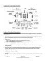
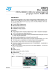
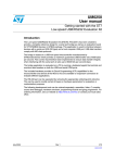
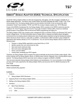
GPS2058 Module Evaluation Kit
User Manual
April, 2008
Rev 1.3
Table of Contents
Page
2
3
3
4
4
5
5
7
8
Topic
Introduction
Kit Contents
Getting Started – Quick Guide
Description of Contents
Minimum System Requirements
Evaluation Kit Component Diagram
Features/Functional Descriptions
Procedure for Establishing an RS-232 Connection
FAQ
Introduction
The GPS2058EVK evaluation kit provides a complete hardware and software platform to test and evaluate the
DeLorme GPS2058 GPS receiver module for integration into custom applications. This kit contains all the
components of a complete GPS receiver system and may also be used as a reference design. All of the necessary
components to evaluate the GPS2058 module, including development board, antenna, and cables are included. A
copy of DeLorme Street Atlas® USA 2008 is also provided to demonstrate how seamlessly the evaluation kit can
interface with software mapping products for use as a GPS navigation system.
This user guide describes the hardware items supplied with the evaluation kit and provides guidelines on the set-up
and operation of the kit. We recommend that you familiarize yourself with the features before applying power and
operating the unit.
Technical information and performance characteristics relating to the GPS2058 module can be found in the
GPS2058 technical specification on our website: http://www.delorme.com/gpsmodules
This guide is intended to provide you with detailed information on how to use this kit with the DeLorme GPS2058
module, however, this kit has also been designed to support future generations of DeLorme modules. Throughout
this document the convention used to identify features that are not used with the GPS2058 module will be identified
as “future” features to simplify the documentation. When new modules are released, additional documentation will
be made available to describe these features.
Rev. 1.3
Page 2 of 8
http://www.delorme.com/gpsmodules
4/25/2008
Kit Contents
Your GPS2058EVK kit contains the following:
1. GPS2058 evaluation board with module, in plastic case
2. Active antenna
3. USB cable
4. 120/220V wall adapter
5. 12V auto adapter
6. Street Atlas USA® 2008 DVD
Getting Started – Quick Guide
1) Verify all kit contents are present.
2) Install Evaluation kit demonstration software (downloaded with this document)
3) Plug the antenna into the antenna connector. Ensure you have a sky view with the antenna for proper
signal reception.
4) Connect the USB cable between the evaluation kit and the PC.
5) Turn on the evaluation kit power. The right LED shows green.
6) The left LED should be flashing red once per second while acquiring a signal.
7) An initial fix should be achieved in approximately 1 minute or less. It may take longer if the antenna view of
the sky is blocked. If no fix is achieved, refer to the troubleshooting section. A fix is achieved when the
Status LED alternates between green and yellow once per second.
Rev. 1.3
Page 3 of 8
http://www.delorme.com/gpsmodules
4/25/2008
Description of Contents
•
GPS2058EVK evaluation board with module
The development board with GPS module is housed in a plastic case. You can open the lid to access the
module and internal connectors, batteries, and switches. The following resources are available on the unit:
• Dual RS232 level serial data I/O ports
• USB port
• Backup battery power source for standby mode demonstration
• Regulated DC power supply to the GPS2058
• GPS and Power Status indicator LEDs on the front panel
• User connectors
•
GPS antenna
The antenna is an active type with powered pre-amp, magnetic base, and RF cable (RG-316) already
terminated with the required SMA connector for the unit. The supplied active antenna is biased at +3.0 VDC,
though the GPS2058 is designed to work with a broad range of active antenna supply voltages – up to 5.0V.
•
USB cable
A USB cable is provided to interface between the development unit and your PC. This cable is terminated at
both ends with connectors to match the PC USB I/O and the type B connector on the evaluation kit.
•
120/240V power adapter
DC power for the development unit can be provided by the AC converter. The AC converter operates from a
nominal 120/240 VAC input and provides a 6 VDC at 500mA output.
•
12V DC power adapter
A car power adapter (12 V) suitable for use with a cigarette lighter socket is provided for road testing.
Minimum System Requirements
To Install the Street Atlas® USA software or the evaluation kit demo software the following system requirements
must be met:
Operating System:
• Microsoft® Windows® Vista™ Home Basic/Home Premium/Ultimate/Business with 512 MB RAM
• Microsoft Windows XP (Service Pack 1 and later) with 128 MB RAM (256 MB recommended)
• Microsoft Windows 2000 (Service Pack 3 and higher) with 64 MB RAM (256 MB recommended)
Laptop or PC Hardware:
• Intel® Pentium 300 MHz or higher processor (600 MHZ recommended)
• 700MB of available hard-disk space required (only if Street Atlas USA® is installed)
• DVD-ROM Drive
• Minimum of one serial port (if your PC only has USB, a USB serial adapter can be used)
For additional details about the Street Atlas USA® software, refer to the program help.
Rev. 1.3
Page 4 of 8
http://www.delorme.com/gpsmodules
4/25/2008
Layout and Component Location
Features/Functional Descriptions
The evaluation kit is self-contained and portable with a minimum number of external connections. You can operate
the kit using a USB cable to the host computer and an active RF antenna (supplied) in a minimum configuration.
Other kit features:
•
DC Options: The kit may be powered from the 12V Car adapter, 120/240V DC adapter, USB power, or two AA
Batteries. Note that only one power source is necessary for the kit to function.
•
Power Switch
• When on without batteries, the entire unit is powered from DC or USB.
• When off without batteries, the entire unit is off.
• When on with batteries only, the entire unit is powered from the batteries.
• When off with batteries only, the module is placed in standby mode.
•
USB: Low-speed USB 2.0, standard Type B connector. The primary interface to a PC and kit may be powered
from the USB port.
•
RS232: Two ports; one for standard NMEA GPS messaging and one for debug messages. Baud rates are
selectable using the inside DIP switch. RS232 ports may be switched between DCE & DTE connections
through the front panel switches.
•
JTAG Interface: For factory updates
•
Standard RF connector, SMA type: Although one is supplied, it fits many available active RF antennas. Limited
to 150mA.
Rev. 1.3
Page 5 of 8
http://www.delorme.com/gpsmodules
4/25/2008
•
Power Indicator (right-side Bi-color LED)
• DC On, Battery Good = Green
• DC On, Battery Weak = Yellow-Orange
• DC Off or not present, Battery Weak = Red
• Other conditions = No indication
•
Reset Switch: Available from the front panel. Signals a reset directly to the module; observable on the User
Connectors (Refer to schematic).
•
Battery Holder: 2 AA in coin-type holder (end-to-end), accessible under the lid.
•
User Connector: Accessible under the lid for probing and or custom development. One connector is 20 pins
and one is 24 pins; both are shrouded headers The headers expose 24 user I/O pins (with some restrictions), 7
DC voltages, multiple ground connections, and five special functions. Refer to the schematic for detailed
description of each pin function.
•
3-Pin Header: Used to select module type (affects positions 2 and 3 of the DIP Switch).
•
DIP Switch functions (0 = Open, 1 = Closed, X = Don’t Care) [default configuration = all open]
• Switch 1,2,3,4,5 = For future features.
•
GPS Signal Indicator (left Bi-color LED), signaled from the module
• PPS available (acquiring) = Flashing Red
• Track Lock = Green
• Track and PPS = Yellow-Orange
• A normal sequence will be flashing red during acquisition followed by green alternating with yellow-orange
every second once a fix is achieved.
Rev. 1.3
Page 6 of 8
http://www.delorme.com/gpsmodules
4/25/2008
Procedure for establishing RS-232 serial connections
NMEA Port
1) Disconnect the USB connection (the NMEA and USB share UART0 and may conflict with each other).
2) Connect External AC Adapter as power source.
3) Connect the antenna.
4) Power on the kit.
5) Connect the RS-232 serial cable to the NMEA port (at the back of the EVK).
6) Ensure the NMEA DTC/DTE switch on the left is in the correct position for the cable. Left position for
straight-thru cable, right position for a switch-cable.
7) Ensure all 5 dip switches on SW5 are OFF.
8) Ensure no jumpers are in place on J11 or J12.
9) Open ‘HyperTerminal’ on your PC or Laptop.
a. Enter a new connection name, e.g.; “GPS2058_NMEA”.
b. In the “Connect To” dialog box, open the drop-down for “connect using:” and select the appropriate
COM port for your connection.
c. Set the port settings to 4800-8-N-1, no flow control, click OK
10) You should now see streaming NMEA messages!
11) You may also open the DeLorme GPS Module Eval Kit Software:
a. Click on “Initialize GPS” button, (3rd down on the right, looks like earth with 4 satellites around it)
b. Choose “generic NMEA” device
c. Select the appropriate COM port
d. Settings 4800,8,N,1
e. Click Finish
12) You should now also see streaming NMEA Messages in the “Receiving Data” window, and be able to view
other tabs such as the satellite status.
DeBug Port
1) The USB connection may be left intact (the Debug port uses UART1 and will not conflict with USB)
2) Connect External AC Adapter as power source, or use USB power.
3) Connect the antenna
4) Power on the kit
5) Connect the RS-232 serial cable to the Debug port (towards the front of the EVK)
6) Ensure the Debug DTC/DTE switch on the right is in the correct position for the cable. Left position for
straight-thru cable, right position for a switch-cable.
7) Ensure all 5 dip switches on SW5 are OFF
8) Ensure no jumpers are in place on J11 or J12
9) Open ‘HyperTerminal’ on your PC or Laptop
a. Enter a new connection name, e.g.; “GPS2058_Debug”
b. In the “Connect To” dialog box, open the drop-down for “connect using:” and select the appropriate
COM port for your connection.
c. Set the port settings to 38400-8-N-1, no flow control, click OK
10) You should now see streaming debug messages!
Serial Connections - Sending NMEA commands with Hyperterminal
The best way to send NMEA commands with HyperTerminal is to create a text file with the NMEA commands on
separate lines (be sure to hit <return> at the end of each line, which is equivalent to <cr><lf>). Once the test file is
created open HyperTerminal and establish the connection, to send the command choose ‘Transfer – Send Text
File…’ and browse to find the command file.
Rev. 1.3
Page 7 of 8
http://www.delorme.com/gpsmodules
4/25/2008
+
FAQ
Q: Why don’t the LEDs light up when I apply power?
A: If you’re using either USB or external DC, the power LED (on the right) should be illuminated. If the batteries are
inserted, this won’t be illuminated unless the batteries are low. If power is OK, then the GPS LED (on the left)
should be pulsing about once per second. If this LED is not pulsing, check the module alignment– see “How are
modules aligned” below.
Q: Why can’t I get a fix?
A: Check the LEDs first! (See question immediately above.) The color of the GPS LED is important: red-to-off
means the module is hunting, orange-to-green means a fix is achieved. After three minutes, if no fix is achieved
(and the GPS LED is pulsing), then check the antenna. The connection should be tight and the position of the
antenna should have a relatively unobstructed sky view. In general, reductions in signal strength still permit a fix
though it takes a little longer to achieve TTFF (time to first fix). However once a fix is achieved, the link should
remain relatively stable. Using the provided evaluation kit demo software you can also check the signal-to-noise
levels of the individual satellite signals – they need to be greater than 25dB in order to obtain an initial fix. Good
SNR values are in the range of 30-45dB or higher. If you are still unable to obtain a fix the best thing to do is to go
outside with an unobstructed sky view and test it there initially to eliminate other variables.
Q: How does weather and environment affect GPS signal reception?
A: In general, a GPS fix can be achieved in a variety of circumstances; however, certain atmospheric disturbances
can create scattering which reduces the quality of the signal. Moisture can play a role– rain, for example, is not
always a problem, though dense clouds can be. Other factors, such as solar flares, can cause difficulties. It is
important to note the environmental conditions when evaluating any GPS solution.
Q: Where do I place the antenna?
A: Examples are on the roof of a car or the dashboard, if the sky view is clear. Indoors, it’s best to place the
antenna near a window. A window view, however, will limit the geometry of the GPS constellation and give poor
accuracy, or a 3-D fix may not be obtainable if 4 satellites are not visible. For both automotive and indoor usage,
the type of glass, particularly metalized glass, may affect the performance. Setting the antenna on a windowsill may
not be enough of a sky view to obtain a fix, and even if a fix is obtained the accuracy may not be that good since
most of the sky view will be blocked. Remember – the position fix is triangulated from the satellite signals, so the
wider the constellation view, the better the accuracy.
Q: How are modules aligned and how do I change modules?
A: The GPS2058 module comes pre-installed onto an adapter board that fits into the evaluation kit. Alignment
between the adapter card and the spring loaded contacts in the evaluation kit is very good, but occasionally the
adapter can be slightly misaligned. You can loosen the screws for the adapter card and shift the adapter slightly
and re-snug the screws to adjust alignment.
Q: Why can’t I establish a USB connection: “USB Device Not Recognized”
A: Early versions of the evaluation kit may be sensitive to low/reduced USB voltages, and if your laptop or PC USB
voltage levels are about 4.75v or less the kit may not be recognized as an Earthmate GPS device. The short term
fix is to use the supplied wall power adapter even when USB is connected. For the long term fix, please contact us
at [email protected] for a replacement or the instructions on how to change one component to overcome
this problem.
Q: Why won’t the module respond to commands sent across the serial connection?
A: Some kits are more sensitive to this than others and the problem stems from a component that has a normal
variation in input leakage that robs current from the signal path. If you are experiencing this issue please contact us
at [email protected] for the instructions on correcting this problem.
Rev. 1.3
Page 8 of 8
http://www.delorme.com/gpsmodules
4/25/2008
5
3
12V
J1
8
Vcc
OUT
1
2
SYNC
3
INH
4
COMP
FB
5
VREF
6
GND
7
DC Power Jack
D2
3V3
C33
1000pF
C1
10uF
SW1
D3
MA2YD2100L
D4
MA2YD2100L
1
2
R4 62K
3V3
L2
U2
15uH
R5
100K
1%
+
C4
47uF
Low ESR
7
LX
OUT
8
5
SHDN
FB
1
2
LBI
LBO
3
REF
GND
6
E
R6
62K
Q1
2N3906
1%
2xAA_Coin
MA22D1500L
1
J2
R3
3K3
R8
82
C3
22pF
Off/Standby
D10
VBATT
R2
5K6
R37
100
E-L5970D
MA2YD2100L
EXT3V3
22uH
MA2YD2100L
USB5V
2
L1
U1
D1
1
2
3
E
4
C5
1uF
R38
100
C6
10uF
C34
1000pF
4
C7
L6920DB
R7
100
+
C8
47uF
Low ESR
0.1uF
C9
1uF
STDBYIN_WAKEUP
D5
BRPG1211C
G
4
Main Power Slide Switch
1
R1
4K7
R
D
POWER LED:
GREEN = DC On, Battery Good
YELLOW = DC On, Battery Low
RED = No DC, Battery Low
2
D
3
C2
220pF
On/Wakeup
When batteries are present, the main
switch operates as Wakeup-Standby.
Without batteries, it acts as On-Off.
VADC
3V3
20-pin developer's connector
1
J12
HEADER 1x2
nSTDBYI
BOOTEN
AIN1
AIN3
2
J12 provides an easy way to
access the VADC and 3V3
supplies but should not
be jumpered.
Mod14_rsvd
PPS
nRESET
1
3
5
7
9
11
13
15
17
19
2
4
6
8
10
12
14
16
18
20
24
22
20
18
16
14
12
10
8
6
4
2
Mod37_rsvd
TRACKLED
UART1RX
UART0RX
GPIO2_B
GPIO0
GPIO2_A
USBDP
nSTDBYO
Wakeup
AIN0
AIN2
Mod13_rsvd
Mod15_rsvd
USBOE
USBRST
HEADER_10x2
USB5V
12V
C
J3
23
21
19
17
15
13
11
9
7
5
3
1
Wakeup
Mod36_rsvd
UART1TX
UART0TX
GPIO3_B
GPIO1
GPIO3_A
USBDN
R9
10K
1
3
5
7
9
11
13
15
17
19
2
4
6
8
10
12
14
16
18
20
nJTRST
JTDI
JTMS
JTCK
nRESET
JTDO
HEADER_10x2_RA
HEADER_12x2
VBATT
B
JTAG Port
J5
J4
C
3V3
24-pin developer's connector
EXT3V3
3V3
VOUT
B
Connectors J4, J5 and J6 are shown as oriented in the evaluation kit.
Note: GPIO2_A/B & GPIO3_A/B are selected
from J10A (left module connector) and J10B
(right module connector) via switch on GPS2058
module adaptor card; switch-down selects
GPIOx_A and switch-up selects GPIOx_B
3V3
SW2
R10
10K
nRESET
Pushbutton_RESET
A
nRESET
C10
A
0.1uF
DeLorme, Yarmouth, ME
Title
Size
B
Date:
5
4
3
2
drawn by JP/Hardware
DeLorme GPS Module Evaluation Kit, Main Power and Connectors page
Document Number
DeLORME_GPS_MODULE_EVK1_SCHEMATIC
Wednesday, April 23, 2008
Sheet
1
Rev
C
1
of
2
3
2
1
USB5V
C21 & C22 provide
decoupling for
U5 pins 1 & 34
DCE
8
5
4
9
5
NMEA: 4800 8-N-1
(default rate)
6
7
8
9
C2-
3
V+
2
DCE
17
16
8
9
3
4
C17
C18
0.1uF
0.1uF
C1+
C16
0.1uF
C1SHDN
V-
EN
T1OUT
R1IN
T2OUT
R2IN
2
4
20
nSTDBYO
R11
180
1
T1IN
R1OUT
13
15
UART0TX
UART0RX
T2IN
R2OUT
12
10
UART1TX
UART1RX
D6
BAS16
D8
BAS16
D7
BAS16
18
17
16
15
14
13
11
10
PB0/AIN0
PB1/AIN1
PB2/AIN2
PB3/AIN3
PB4/AIN4/IT5
PB5/AIN5/IT6
PB6/AIN6/IT7
PB7/AIN7/IT8
7
6
5
USBOE
PC0/RDI
PC1/TDO
PC2/USBOE
VDD
VDDA
VPP/TEST
1
34
12
R13
10K
R21
OSCOUT
2
OSCIN
3
RESET
8
USBVCC
33
USBDM
USBDP
32
31
C19
470
C22
C23
0.1uF
0.1uF
4_7uF
Note for Rev. C:
L3 is replaced by R35
5.6pF
Y1
24MHz
C20
USBRST
R14
C21
D
R22
2M2
5.6pF
1K5
R15
24
R19
24
R16
24
R20
24
ST72F63BK2
R17
ST3222E or MAX3222
R17-R18 are 24
not populated
Short Handle Slide
R18
24
C24
C25
22pF
22pF
VOUT VADC 3V3
J10A
RS232_Dsub-9
R28
2K2
10K
C28
C29
0.1uF
3V3
0.1uF
GPS LED:
GREEN = Track Lock
YELLOW = Track + PPS
RED = PPS only
D9
BRPG1211C
R30
1K
C30
3V3
B
R31
R34
120
Q3
1K
22K
Mod13_rsvd
Mod14_rsvd
Mod15_rsvd
PPS
USBDP
USBDN
GPIO2_A
GPIO3_A
R
R32
82
R29
Q2
2N3904
1uF
G
4
VOUT
1
R27
STDBYIN_WAKEUP
nSTDBYO
nSTDBYI
Wakeup
nRESET
AIN0
AIN1
AIN2
AIN3
nSTDBYO
nSTDBYI
Wakeup
nRESET
2
DEBUG: 38.4K 8-N-1
3
C
DTE
5
6
7
SW4
1
C2+
C15
0.1uF
Short Handle Slide
RS232_Dsub-9
J7
0.1uF
U4
19
3
PA0/MCO
PA1/SDA/ICCDATA
PA2/SCL/ICCCLK
PA3/EXTCLK
PA4/ICAP1/IT1
PA5/ICAP2/IT2
PA6/OCMP1/IT3
PA7/OCMP2/IT4
0.033
2
2
C14
29
28
24
23
22
21
20
19
VSSA
VSS
DTE
18
D
1
R12
10K
30
4
7
3V3
VCC
6
SW3
GND
J6
R35
Q4
2N3904
R33
GPIO0
GPIO1
GPIO2_B
GPIO3_B
JTCK
JTMS
JTDI
JTDO
nJTRST
UART0RX
UART0TX
UART1RX
UART1TX
TRACKLED
Mod36_rsvd
Mod37_rsvd
BOOTEN
2N3904 1K
SW5
R36
10K
O1 2 3 4 5
F
F
R35
10K
GPIO2
GPIO3
UART0RX
UART0TX
UART1RX
UART1TX
5PST_DIP
(Reserved)
SW5: Open = Off
(Switches default off)
BOOTEN
3V3
U3
A
nSTDBYO
Note: GPIO2 & GPIO3 can be switched between
J10A (left module connector) and J10B (right
module connector) via switch on GPS2058
module adaptor card
1
IN
3
INH
C11
1uF
BYP
1
SMA_RF_CONN
L4
100nH
Coplanar Waveguide, Z=50ohms,
for Module Pin 19 (RF Signal)
referred to Module Pins 18 & 20
(RF Grounds), extending from
J10B to J8
5
4
3
2
C31-C32 and L4-L6 are
placed as close to the
module pins as possible.
LD2985BM30R
Antenna Power
OUT 5
GND
J11
HEADER_1x3
2
1
2
3
J8
Note: Antenna Power is not available
at headers J3 or J4 because of the
potential for noise injection into
the active antenna network.
0.1uF
2.2uF
C31
1000pF
4
3
Left Module Connector
1
2
3
4
5
6
7
8
9
10
11
12
13
14
15
16
17
18
19
20
GND, Pin 1
VCC IN, Pin 2
nSTDBYO, Pin 3
nSTDBYI, Pin 4
Wakeup, Pin 5
nRESET, Pin 6
AIN0, Pin 7
AIN1, Pin 8
AIN2, Pin 9
AIN3, Pin 10
VADC, Pin 11
VOUT, Pin 12
(Reserved), Pin 13
(Reserved), Pin 14
(Reserved), Pin 15
PPS, Pin 16
USBDP, Pin 17
USBDN, Pin 18
GPIO2/I2C_CK, Pin 19
GPIO3/I2C_D, Pin 20
1
2
3
4
5
6
7
8
9
10
11
12
13
14
15
16
17
18
19
20
GPIO0/SPIMISO, Pin 21
GPIO1/SPIMOSI, Pin 22
GPIO2/SPI_CK, Pin 23
GPIO3/SPI_SS, Pin 24
JTCK, Pin 25
JTMS, Pin 26
JTDI, Pin 27
JTDO, Pin 28
nJTRST, Pin 29
U0RX, Pin 30
U0TX, Pin 31
U1RX, Pin 32
U1TX, Pin 33
TRACKLED, Pin 34
(Reserved), Pin 35
(Reserved), Pin 36
BOOTEN, Pin 37
RF-GND, Pin 38
RF-IN, Pin 39
RF-GND, Pin 40
J10B
C32
L6
100pF
100nH
2
C
B
Right Module Connector
A
Title
Size
B
Date:
5
USB_TypeB
27nH
DeLorme, Yarmouth, ME
C13
J9
L5
4
C12
1
U5
4
4
3
5
drawn by JP/Hardware
DeLorme GPS Module Evaluation Kit, Module and Communications page
Document Number
DeLORME_GPS_MODULE_EVK1_SCHEMATIC
Wednesday, April 23, 2008
Sheet
1
Rev
C
2
of
2
5
4
3
2
1
RF-GND
RF-IN
RF-GND
BOOTEN
Mod36_rsvd
Mod35_rsvd
TRACKLED
U1TX
U1RX
U0TX
TP1
TP2
R2 0.1
R1
VCC Out
1
2
3
4
5
6
7
8
9
10
GND
VCC IN
nSTDBYO
nSTDBYI
WAKEUP
nRESET
AIN0
AIN1
AIN2
AIN3
U0RX
nJTRST
JTDO
JTDI
JTMS
JTCK
USBDN
USBDP
GPIO5/CANTX
GPIO4/CANRX
VADC
V18
Mod13_rsvd
Mod14_rsvd
Mod15_rsvd
PPS
GPIO0/SPIMISO
GPIO1/SPIMOSI
GPIO2/SPI_CK/I2C_CK
GPIO3/SPI_SS/I2C_D
GND
VCC In
nSTDBYO
nSTDBYI
Wakeup
nRESET
AIN0
AIN1
AIN2
AIN3
C1 10
40
39
38
37
36
35
34
33
32
31
30
29
28
27
26
25
24
23
22
21
GPS2058
SW1
11
12
13
14
15
16
17
18
19
20
10nF
U0RX
nJRST
JTDO
JTDI
JTMS
JTCK
30
29
28
27
26
25
24
23
22
21
B
1
DPDT Slide
GPIO1/SPIMOSI
GPIO0/SPIMISO
B
GPIO2/I2C_CK
GPIO3/I2C_D
TP3
V18
Test Point
R3 0.1
GPIO2/SPI_CK
GPIO2/SPI_CK/I2C_CK
1
2
3
4
R4 10
SPI GPIO3/SPI_SS
GPIO5/CANTX
GPIO4/CANRX
TP4
Test Point
C
I2C
GPIO3/SPI_SS/I2C_D
VADC
Mod13_rsvd
Mod14_rsvd
Mod15_rsvd
PPS
USBDP
USBDN
PCB Contacts
RF-GND, Pin 40
RF-IN, Pin 39
RF-GND, Pin 38
BOOTEN, Pin 37
(Reserved), Pin 36
(Reserved), Pin 35
TRACKLED, Pin 34
U1TX, Pin 33
U1RX, Pin 32
U0TX, Pin 31
U0RX, Pin 30
nJTRST, Pin 29
JTDO, Pin 28
JTDI, Pin 27
JTMS, Pin 26
JTCK, Pin 25
GPIO3/SPI_SS, Pin 24
GPIO2/SPI_CK, Pin 23
GPIO1/SPIMOSI, Pin 22
GPIO0/SPIMISO, Pin 21
PCB Contacts
1
C
1
2
3
4
5
6
7
8
9
10
11
12
13
14
15
16
17
18
19
20
1
Test Point
1
J10
GND, Pin 1
VCC IN, Pin 2
nSTDBYO, Pin 3
nSTDBYI, Pin 4
Wakeup, Pin 5
nRESET, Pin 6
AIN0, Pin 7
AIN1, Pin 8
AIN2, Pin 9
AIN3, Pin 10
VADC, Pin 11
VCC OUT, Pin 12
(Reserved), Pin 13
(Reserved), Pin 14
(Reserved), Pin 15
PPS, Pin 16
USBDP, Pin 17
USBDN, Pin 18
GPIO2/I2C_CK, Pin 19
GPIO3/I2C_D, Pin 20
J11
RF-GND2
RF-IN
RF-GND1
BOOTEN
Mod36_rsvd
Mod35_rsvd
TRACKLED
U1TX/BOOTTX
U1RX/BOOTRX
U0TX/BOOT0
U1
Test Point
D
40
39
38
37
36
35
34
33
32
31
D
D1
MMBZ5222BLT1G
C2
J1 provides access to
V18 (Pin1,2) and CAN (Pin3,4)
0.1uF
J1
Header_4pos
A
A
MC/JP
Title
Size
B
Date:
5
4
3
2
GPS2058 Module Adapter PCB
Document Number
DeLORME_GPS2058_EVK_Adapter
Wednesday, April 23, 2008
Rev
C
Sheet
1
1
of
1