1
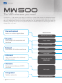
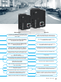
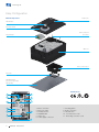
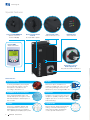
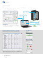
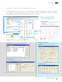
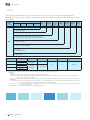
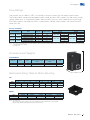
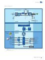
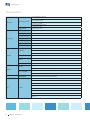
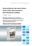
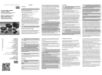
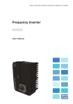
Motors | Automation | Energy | Transmission & Distribution | Coatings MW500 Decentralized VSD MotorDrive www.weg.net The VSD wherever you need The MW500 is a high performance product dedicated for induction motor control, with embedded features and a high protection degree of IP66 / NEMA 4X which allow decentralized installation directly on the motor or on a wall. Designed exclusively for industrial or professional use, the decentralized WEG VSD adds a great deal of flexibility, allowing the user to install the product near to the controlled motor, thus eliminating the necessity of long cables and panels. Decentralized Indoor or outdoor applications Characteristics Motor or wall assembly Flexible Wide range of accessories and functions Plug-in module Flash memory module Robust IP66/NEMA 4X outdoor enclosure SoftPLC Increasing the ruggedness and durability Efficient High performance for machines and processes Functions to streamline operation and performance Reliable Same trustworthiness of WEG products WEG quality Integrated Fieldbus networks 2 MW500 - MotorDrive Communication networks www.weg.net Advantages Benefits It is possible for the MW500 to be assembled on a wall or, using the terminal box coupling directly over the W22 or W21 motors. Makes the commissioning easy, saving space and cabling, in other words, reducing cost for all installation. The optional communication network and I/O modules are fast and easily to be installed, allowing adaptation of the standard VSD to each application. Time saving, standardization and optimized costs according to the necessity. Within seconds, it is possible to download the SoftPLC program and parameters setup from a MW500 to others without powering them up. Fast, easy and reliable programming for manufacturers that produce machines in large scale. Built-in PLC (SoftPLC), allowing the VSD, motor and application to work in an interactive way. It allows the user to implement customized logic and applications. It eliminates the necessity of an external PLC, reducing costs, optimizing space and simplifying the system. Complete protection against contact with internal live parts, avoiding the entrance of dust or water coming from jets. Panel not required, reducing the installation costs. PID: process control. Sleep: disables the VSD automatically. Energy saving. Flying start: allows to start a motor that was running freely, accelerating it from the speed at which it was running. It allows fast operating response of the machine and prevents occasional mechanical breakdowns. Ride through: keeps the VSD in operation during voltage dips. It prevents machine stoppage and downtime. 100% of the VSDs are tested with load at the factory under rated conditions. High reliability. Protection against ground fault, short circuit, over temperature and others. It prevents damage to the inverter which can be caused by adverse situations, normally external factors. Thermal protection of IGBTs based on manufacturer curve. Conformal Coating (Tropicalization) as Standard. Classified as 3C2 according to IEC 60721-3-3. VSD lifetime is extended: protection against chemically active substances, related to contamination from the atmosphere. CANopen, DeviceNet, Profibus-DP and Modbus-RTU. Full integration with process network. MW500 - MotorDrive 3 www.weg.net Easy Configuration Main Components Frontal cover LED indicators Disconnect switch Motor connection box screws Plug-in module Main case Motor connection box Motor seal Wall adapter plate (accessory not provided with the drive) Certifications 11 1 2 10 9 3 4 5 8 6 7 4 MW500 - MotorDrive 1 - Motor connection 2 - Motor PTC input 3 - S10 dip-switches 4 - Simplified label 5 - Plug-in slot 6 - Power supply connection 7 - Grouding points 8 - Brake connection 9 - LED indicators 10 - Connection box screw 11 - Grounding connection screw www.weg.net Applications Centrifugal pumps Compressors Process pumps Fans/exhaust fans Mixers/bottlers Washers/driers Conveyor belts General machinery Up to 50 ºC on motor mounting MW500 - MotorDrive 5 www.weg.net Special Features Conector IP66/NEMA 4X Special conector for Remote HMI (M8) Analog Potentiometer Built-In No need HMI to operate Fins Instead of Fan Reduce maintenance cost LED Indicators Status indication Remote HMI Simple and intuitive Switch-Disconnector Built-In (Optional) Easy and safe machine maintenance Characteristics = Bus connection DC (frame B only) = Connection for brake resistor Increasing the lifetime, protecting the electronic boards against corrosive atmospheres. Classified as 3C2 according to IEC 60721-3-3. S/L2 With C2/C3 options, the VSD faces a Power supply T/L3 redution in the EMC level, some cases even more, taking advantage of the motor and VSD distance, thus increasing the EMC class. IP66/NEMA 4X Protection Degree Black Color Key to the decentralized solution, the IP66 provides protection against contact with internal live parts and the ingress of dust or water. The black color increases the enclosure dissipation capability, helping the drive support up to 50 °C on motor mounting without derating. SoftPLC SuperDrive G2 Functions to streamline operation and increase performance, in many cases eliminating the necessity of an external PLC, optimizing and simplifying the system. Special software, allowing the parameter setting, command and monitoring of MW500 Keypad (remote) VSD, in this last option, simulating an oscilloscope with Trend function. DC- Precharge R/L1 RFI filter Recfilter Disconnect switch BR PE Breaking IGBT RFI Filter DC+ DC link capacitors bank Conformal Coating Inverter IGBT Cur POWER CONTROL PLUG-IN MODULE 2) XC10 MW500 - MotorDrive Supplies for electronics and interfaces between power and control CPU 32 bits "RISC" PC 6 CONTROL Software WLP SuperDrive1) Modbus Modbus Digital input (DI1 to DI4)1) RS485 Interfaces (RS232, RS485 or USB) User’s Plug-in Card EEPROM (memory www.weg.net MORE savings! Space saving and flexible solution Increased ruggedness Cost savings on cables Reduced installation costs Easy commissioning Panel not required + costs Up to space 40% of cost reduction www.weg.net SuperDrive G2 Software application to program, control and monitor WEG VSDs. To connect MW500 to a computer it is necessary to use a plug-in module. USB plug-in module Friendly environment FREE download at www.weg.net Trend Function Online graphic monitoring of parameters/variables JJ Possibility to export an image with the respective graph based upon the selected period JJ Changing and Monitoring Parameters in a List/Table Parameter settings can be stored in a computer file format. Status Monitoring Operation with HMI Online parameter editing. JJ JJ 8 pload/download parameters from the PC to the MW500 and vice U versa Offline editing of the parameters stored on the PC MW500 - MotorDrive www.weg.net SoftPLC - Built-In in the Standard Product Functionalities of a PLC available as standard, allowing the creation of applications. The WLP software and the SoftPLC functionality are a smart and simple way to make your MW500, motor and application work together. Plug-in module required to connect with a computer. Easy programming: Ladder Speed reference Contacts and coils Trace Function JJ Online graphic monitoring of parameters/ variables JJ Configurable up to six channels Comparators and math functions Counters and timers FREE download at www.weg.net PID User block protected by password Online Monitoring Parameters/Variables List Enable/Disable I/Os It simplifies and speeds up the validation of the application. Parameter Edition For changing the parameters values. I/Os Monitoring MW500 - MotorDrive 9 www.weg.net Coding The MW500 code identifies its construction characteristics, nominal current, voltage range and optionals. Using the smart code, it is possible to select the MW500 required for your application simple and quickly. Product and series MW500 Model identification Frame size Rated current N° of phases Rated voltage A 02P6 T 4 Braking1) Degree of protection¹) Conducted emission level¹) Disconnect switch Terminal box adaptor Hardware version Software version DB 66 C2 DS A56 H00 --- Check table below NB = without dynamic braking DB = with dynamic braking 66 = IP66/NEMA 4X Blank = with no RFI filter C2 = according to category 2 of IEC 61800-3 standard, with internal RFI flter C3 = according to category 3 of IEC 61800-3 standard, with internal RFI flter MW500 Blank = without disconnect switch DS = with disconnect switch A56 = 56 mm motor terminal box adaptor A70 = 70 mm motor terminal box adaptor Blank = standard H00 = without plug-in module Blank = standard Sx = special software Frame sizes A A B Output current Input Power supply voltage 04P3 = 4.3 A S = single phase power supply 2 = 200... 240 V T = three-phase power supply 4 = 380... 480 V 06P0 = 6.0 A 02P6 = 2.6 A 04P3 = 4.3 A 06P5 = 6.5 A Braking Degree of protection Conducted emission level2) DB 66 Blank or C2 10P0 = 10 A Notes: 1) To know which models have these options in the standard product the above table should be checked. 2) RFI filter. Categories: - Category C1: inverters with voltages below 1,000 V, for use in the First Environment. - Category C2: inverters with voltages below 1,000 V, with plugs or mobile installation, when used in the “First Environment”, must be installed and started-up by a qualified professional. - Category C3: inverters with voltages below 1,000 V, developed for use in the Second Environment and not designed for use in the “First Environment”. Environments: - First Environment: environments that include household installations, such as buildings directly connected, without intermediate transformer, to a lowvoltage power supply grid, which supplies buildings used for domestic purposes. - Second Environment: includes all the buildings other than those directly connected to a low-voltage power supply grid, which supplies buildings used for domestic purposes. For the RFI filters of external installations, refer to the MW500 user manual. 10 MW500 - MotorDrive www.weg.net Drive Ratings The correct way to select a VSD is matching its output current with the motor rated current. The tables below present the expected motor power for each VSD model. Use the motor power ratings below only as a guidance. Motor rated currents may vary with speed and manufacturer. IEC motor powers are based on WEG 4-pole motors; NEMA motor powers are based on NEC table 430-150. Ratings and Models Power supply In (V) Single-phase 200-240 Three-phase 380-480 Three-phase 380-480 Maximum motor power1) Model Frame size Output current (A) MW500 A 04P3 S2 DB 66 A2) 4.3 MW500 A 06P0 S2 DB 66 A2) 6.0 MW500 A 02P6 T4 DB 66 A2) 2.6 1.1 MW500 A 04P3 T4 DB 66 A2) 4.3 1.5 MW500 B 06P0 T4 DB 66 B 6.5 MW500 B 10P0 T4 DB 66 B 10 IEC (kW) NEMA (HP) 0.75 50 Hz - 230 V 50 Hz - 415 V 1 60 Hz - 230 V 1.1 1.5 1.5 2 60 Hz - 460 V 2.2 3 4 5 Notes: 1) U se motor power ratings below only as a guidance. Motors are rated for 400 V, 50 Hz, 4-pole. The right way to size a VSD is matching its output current with the rated motor current. 2) Coming soon. Dimensions and Weights IP66/NEMA 4X Frame size H mm (in) W mm (in) D (without disconnect switch) mm (in) D (with disconnect switch) mm (in) Weight Kg (lb) A1) 240 (9.45) 165 (6.50) 125 (4.92) 172 (6.77) 3,7 (9.14) B 269 (10.61) 269 (10.61) 141 (5.55) 188 (7.39) 5,3 (11.68) H Note: 1) Coming soon. D Mechanical Sizing Table for Motor Mounting W IEC 56 mm 70 mm Frame 71 80 90 100 112 A1) ü ü ü ü ü ü ü ü B 110 mm 132 160 180 ü Note: 1) Coming soon. NEMA 56 mm 70 mm 110 mm Frame 143T/145T 182T/184T 213T/215T A1) ü ü ü B ü ü ü 254T/256T 284T/286T Notes: 1 ) Coming soon. Motor frame size for W22 and W21 series: Standard Efficiency (IE1), High Efficiency (IE2), Premium Efficiency (IE3), Multimounting (standards and compact versions). MW500 - MotorDrive 11 www.weg.net Accessories and Optionals The MW500 VSD was developed to meet the hardware configurations required by a wide range of applications. The table below presents the available options: Option Type1) RFI filter Optional Braking IGBT Optional Disconnect switch Optional Wall mounting kit Accessory Description Used to reduce the disturbance conducted from the CFW500 to the power supply, in the high frequency band (>150 kHz), according to standards 61800-3 and EN 55011 Used in high-inertia applications for the fast stop of the motor by means of an external braking resistance. Resistance not included. For the calculation of the braking resistance, refer to the MW500 user manual A disconnect switch built-in the product for easy and safe maintenance. This optional makes the VSD IP65 An adaptation plate for assemble the drive on the wall For more information please check the user manual Optional item code2) Accessory model Available C2 or C3 - Factory installation only DB - Factory installation only DS - Factory installation only MW500 - KCFB User installation - Motor mounting kit Accessory An adaptation box for assemble the drive on the motor. For more information please check the user manual - I/O expansion modules (plug-in)3) Accessory Used to configure the I/O points according to the needs of the application/machine - Communication module (plug-in)3) Accessory Used for the communication of the MW500 with the main networks of the market (fieldbus) - Flash memory module (plug-in)3) Accessory Remote HMI Accessory Cables for remote HMI Accessory Used to download the programming of a MW500 to others without having to power them up Used to transfer the operation to the panel door or machine console. Maximum distance of 10 m. Degree of protection IP54 Special cable desing using M8-DB9 connector with 0.5 m, or using the same cables of CFW the MW500 to the remote HMI (CFW500-HMIR) MW500 - KAIM - A55 MW500 - KAIM - B56 MW500 - KAIM - B70 CFW500-IOS CFW500-IOD CFW500-IOAD CFW500-IOR CFW500-CUSB (USB) CFW500-CCAN (CANopen /DeviceNet) CFW500-CRS232 CFW500-CRS485 CFW500-CPDP (Profibus-DP) User installation - - - CFW500-MMF - - CFW500-HMIR - - MW500-CCHMIR0.5M CFW500-CCHMIRXM, where cables with lengths (X) of 1, 2, 3, 5, 7.5 and 10 meters - Plug-In Modules Specification3) Plug-in module IOS IOD IOAD IOR CUSB CCAN CRS232 CRS485 CPDP Inputs Outputs Digital Analog Analog Digital relay 4 8 6 5 4 2 2 4 2 1 1 3 1 1 1 1 2 1 1 1 2 1 1 1 1 1 1 1 1 1 4 1 1 1 2 1 Functions Digital transistor 1 4 3 1 1 1 1 1 1 USB port 1 - CANopen/ DeviceNet Fieldbus networks Power supply RS232 RS485 Profibus-DP 10 V 24 V 1 - 1 1 1 1 1 1 1 2 1 1 1 1 1 1 1 1 1 - 1 1 1 1 1 1 1 1 1 1 - Notes: 1) Optional: hardware resources added to the MW500 in the manufacturing process accessory = hardware resource requested as a separated item. 2) Request the product according to the code available on page 10. 3) A ll models of plug-in modules have at least one RS485 port. The CRS485 plug-in module has two RS485 ports. The MW500 allows installing one plug-in module per unit. Step by Step 1 - Remove cover 12 MW500 - MotorDrive 2 - Insert accessory 3 - Close cover Simple! www.weg.net Block Diagram = Bus connection DC (frame B only) = Connection for brake resistor Recfilter Disconnect switch PE Breaking IGBT T/L3 BR DC- U/T1 V/T2 W/T3 DC link capacitors bank RFI filter S/L2 DC+ Precharge R/L1 Power supply Motor Inverter with IGBT’s Current feedback Dedicate knob for reference POWER CONTROL Supplies for electronics and interfaces between power and control CPU 32 bits "RISC" EEPROM (memory) CONTROL PLUG-IN MODULE MW500 Keypad (remote)2) XC10 PC Software WLP SuperDrive1) Modbus Modbus RS485 Interfaces (RS232, RS485 or USB) Power supply 10 V Power supply 24 V Analog output (AO1)1) User’s Plug-in Card Digital output DO1 (RL1) Digital input (DI1 to DI4)1) Digital output DO2 (TR)1) Analog input (AI1)1) Accessory Memory card (Mcard) Notes: 1) The number of analog/digital inputs/outputs, as well as other resources, may vary according to the plug-in module used. Table 7.1 provides a list of the available plug-ins. For further information, refer to the guide supplied with the accessory or the CD-ROM. 2) Not provided with the product. MW500 - MotorDrive 13 www.weg.net Technical Data 1-phase, 200-240 V ac (+10%-15%) 0.75 and 1.1 kW (1 and 1.5 HP) Voltage and power range Power supply 1-phase/3-phase, 200-240 V ac (+10%-15%) 0.25 to 3 HP (0.25 to 2.2 kW) 3-phase, 200-240 V ac (+10%-15%) 2 to 7.5 HP (1.5 to 5.5 kW) 3-phase, 380-480 V ac (+10%-15%) 1.1 to 4 kW (1.5 to 5 HP) Motor connection Supply frequency 50/60 Hz (48 Hz to 62 Hz) Voltage 3-phase, 0-100% of supplied voltage Output frequency 0 a 500 Hz Displacement power factor >0.97 Overload capacity 1.5 x In (drive) for 1 minute every 6 minutes Switching frequency Default 5 kHz (selectable 2.5 to 15 kHz) Aceleration time 0.1 to 999s Deceleration time 0.1 to 999s 40 ºC - for wall mounting installation Temperature 50 ºC - for motor mounting installation using self-ventilation 2% of current derating for each ºC above the specific operating temperature, limited to an increase of 10 ºC Environment Humidity 5% to 95% non-condensing Up to 1,000 m - rated conditions Altitude 1,000 m to 4,000 m - 1% of current derating for each 100 m above 1,000 m of altitude Protection degree IP66/NEMA 4X (the disconnect switch is IP65) Speed regulation: 1% of the rated speed (with slip compensation) V/f control Speed variation range: 1:20 Performance Speed regulation: 1% of the rated speed Vector control (VVW) Speed variation range: 1:30 Braking methods DC current applied to motor dynamic braking Available as standard for frame size B. For frame size A “DB” models has to be used. An extra resistor must be fitted in for dynamic braking capability Overcurrent/phase-phase short circuit in the output Overcurrent/phase-ground short circuit in the output Under/overvoltage Overtemperature in the heatsink Safety Protection Overload in the motor Overload in the power module (IGBTs) External alarm / fault Setting error 14 MW500 - MotorDrive www.weg.net Technical Data - Standards Modbus-RTU All plug-in modules for RS485 and CFW500-CRS232 for RS232 Profibus-DP Plug-in module CFW500-CPDP DeviceNet Plug-in module CFW500-CCAN CANopen Plug-in module CFW500-CCAN AC input chokes For reducing THD AC output chokes For longer motor cables UL 508C Power conversion equipment. UL 840 Insulation coordination including clearances and creepage distances for electrical equipment. EN 61800-5-1 Safety requirements electrical, thermal and energy. EN 50178 Electronic equipment for use in power installations. EN 60204-1 Safety of machinery. Electrical equipment of machines. Part 1: General requirements. Note: For the machine to comply with this standard, the manufacturer of the machine is responsible for installing an emergency stop device and equipment to disconnect the input power supply. EN 60146 (IEC 146) Semiconductor converters. EN 61800-2 Adjustable speed electrical power drive systems - Part 2: General requirements - Rating specifcations for low voltage adjustable frequency AC power drive systems. EN 61800-3 Adjustable speed electrical power drive systems - Part 3: EMC product standard including specifc test methods. EN 55011 Limits and methods of measurement of radio disturbance characteristics of industrial, scientifc and medical (ISM) radio-frequency equipment. CISPR 11 Industrial, scientifc and medical (ISM) radio-frequency equipment - Electromagnetic disturbance characteristics Limits and methods of measurement. EN 61000-4-2 Electromagnetic compatibility (EMC) - Part 4: Testing and measurement techniques - Section 2: Electrostatic discharge immunity test. EN 61000-4-3 Electromagnetic compatibility (EMC) - Part 4: Testing and measurement techniques - Section 3: Radiated, radio-frequency, electromagnetic feld immunity test. EN 61000-4-4 Electromagnetic compatibility (EMC) - Part 4: Testing and measurement techniques - Section 4: Electrical fast transient/ burst immunity test. EN 61000-4-5 Electromagnetic compatibility (EMC) - Part 4: Testing and measurement techniques - Section 5: Surge immunity test. EN 61000-4-6 Electromagnetic compatibility (EMC) - Part 4: Testing and measurement techniques - Section 6: Immunity to conducted disturbances, induced by radio-frequency fields. EN 60529 Degrees of protection provided by enclosures (IP code). UL 50 Enclosures for electrical equipment. Communication Chokes (external as accessory) Safety standards Electromagnetic Compatibility (EMC) Standards Mechanical construction standards MW500 - MotorDrive 15 WEG Worldwide Operations WEG PINTURAS - Pulverlux Buenos Aires Phone: +54 11 4299 8000 [email protected] AUSTRALIA WEG AUSTRALIA Victoria Phone: +61 3 9765 4600 [email protected] www.weg.net/au AUSTRIA WATT DRIVE - WEG Group Markt Piesting Phone: +43 2633 404 0 [email protected] www.wattdrive.com BELGIUM WEG BENELUX Nivelles - Belgium Phone: +32 67 88 84 20 [email protected] www.weg.net/be BRAZIL WEG EQUIPAMENTOS ELÉTRICOS Jaraguá do Sul - Santa Catarina Phone: +55 47 3276-4002 [email protected] www.weg.net/br CHILE WEG CHILE Santiago Phone: +56 2 784 8900 [email protected] www.weg.net/cl ECUADOR WEG ECUADOR Quito Phone: 5144 339/342/317 [email protected] www.weg.net/ec MALAYSIA WATT EURO-DRIVE - WEG Group Shah Alam - Selangor Phone: 603 78591626 [email protected] www.wattdrive.com SINGAPORE WATT EURO-DRIVE - WEG Group Singapore Phone: +65 6 862 2220 [email protected] www.wattdrive.com FRANCE WEG FRANCE Saint Quentin Fallavier - Lyon Phone: +33 4 74 99 11 35 [email protected] www.weg.net/fr MEXICO WEG MEXICO Huehuetoca Phone: +52 55 5321 4231 [email protected] www.weg.net/mx WEG SINGAPORE Singapore Phone: +65 68589081 [email protected] www.weg.net/sg GERMANY WEG GERMANY Kerpen Phone: +49 2237 9291 0 [email protected] www.weg.net/de VOLTRAN - WEG Group Tizayuca - Hidalgo Phone: +52 77 5350 9354 www.voltran.com.mx WEG BALINGEN Balingen Phone: +49 7433 9041 0 [email protected] www.weg-antriebe.de GHANA ZEST ELECTRIC GHANA WEG Group Accra Phone: +233 30 27 664 90 [email protected] www.zestghana.com.gh INDIA WEG Electric India Bangalore - Karnataka Phone: +91 80 4128 2007 [email protected] www.weg.net/in WEG INDUSTRIES INDIA Hosur - Tamil Nadu Phone: +91 4344 301 577 [email protected] www.weg.net/in CHINA WEG NANTONG Nantong - Jiangsu Phone: +86 0513 8598 9333 [email protected] www.weg.net/cn ITALY WEG ITALIA Cinisello Balsamo - Milano Phone: +39 02 6129 3535 [email protected] www.weg.net/it COLOMBIA WEG COLOMBIA Bogotá Phone: +57 1 416 0166 [email protected] www.weg.net/co JAPAN WEG ELECTRIC MOTORS JAPAN Yokohama City - Kanagawa Phone: +81 45 550 3030 [email protected] www.weg.net/jp NETHERLANDS WEG NETHERLANDS Oldenzaal - Overijssel Phone: +31 541 571 080 [email protected] www.weg.net/nl PERU WEG PERU Lima Phone:+51 1 209 7600 [email protected] www.weg.net/pe PORTUGAL WEG EURO Maia - Porto Phone: +351 22 9477705 [email protected] www.weg.net/pt RUSSIA and CIS WEG ELECTRIC CIS Saint Petersburg Phone: +7 812 363 2172 [email protected] www.weg.net/ru SOUTH AFRICA ZEST ELECTRIC MOTORS WEG Group Johannesburg Phone: +27 11 723 6000 [email protected] www.zest.co.za SCANDINAVIA WEG SCANDINAVIA Mölnlycke - Sweden Phone: +46 31 888 000 [email protected] www.weg.net/se UK WEG ELECTRIC MOTORS U.K. Redditch - Worcestershire Phone: +44 1527 513 800 [email protected] www.weg.net/uk UNITED ARAB EMIRATES WEG MIDDLE EAST Dubai Phone: +971 4 813 0800 [email protected] www.weg.net/ae USA WEG ELECTRIC Duluth - Georgia Phone: +1 678 249 2000 [email protected] www.weg.net/us ELECTRIC MACHINERY WEG Group Minneapolis - Minnesota Phone: +1 612 378 8000 www.electricmachinery.com VENEZUELA WEG INDUSTRIAS VENEZUELA Valencia - Carabobo Phone: +58 241 821 0582 [email protected] www.weg.net/ve SPAIN WEG IBERIA Madrid Phone: +34 91 655 30 08 [email protected] www.weg.net/es For those countries where there is not a WEG own operation, find our local distributor at www.weg.net. WEG Group - Automation Business Unit Jaraguá do Sul - SC - Brazil Phone: +55 47 3276 4000 [email protected] www.weg.net Cod: 50051392 | Rev: 00 | Date (m/y): 11/2014 The values shown are subject to change without prior notice. ARGENTINA WEG EQUIPAMIENTOS ELECTRICOS San Francisco - Cordoba Phone: +54 3564 421 484 [email protected] www.weg.net/ar