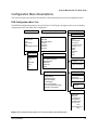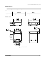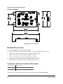
1
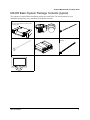
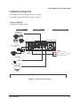
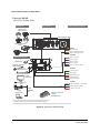
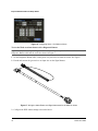
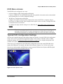
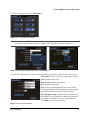
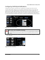
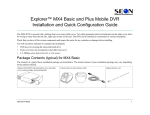
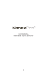
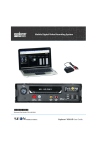
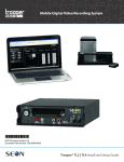
Explorer® MX-HD Basic and Plus Mobile DVR Install and Setup Guide Use this guide to install and configure the Seon Explorer MX-HD DVR. The DVR requires configuration as part of the install process. The Explorer MX-HD DVR is secured with a locking front cover and a cable cover. Two cable grommets (and two knockouts) on the cable cover allow for wiring to enter from the left side, right side, or back of the unit. The DVR can be installed horizontally or vertically. 700-0159 R003 *700-0159* 1 Explorer MX-HD Install and Setup Guide Guide Contents Tools and Equipment, on page 2 MX-HD Basic System Package Contents (typical), on page 3 MX-HD Plus System Package Contents (typical), on page 4 Installation Diagrams, on page 5 Installation Best Practices, on page 7 DVR and Component Installation, on page 8 Other Accessories, on page 13 Hardware Installation Final Checklist, on page 14 DVR Menu Access, on page 15 Typical DVR Configuration Settings, on page 15 vMax Web Laptop Configuration, on page 26 DVR Configuration Uploads, on page 30 Updating the Firmware, on page 38 Configuring DVR Email Notifications, on page 39 Configuration Menu Descriptions, on page 41 Dimensions, on page 67 Related Documents, on page 68 Customer Service Contact Information, on page 68 Tools and Equipment This DVR system must be installed by a professional installer. A professional installer has the experience and equipment to install and configure this DVR system to run properly. Check that you have all the system components and inspect the units for any scratches or damage before installing. Keys included in package contents: • • DVR keys for securing the removable hard drive Front cover keys for securing the removable front cover Configuration equipment: 2 • For on-screen configuration: portable video monitor and trackball mouse • For vMax® Web configuration: laptop and an Ethernet cable. 700-0159 R003 Explorer MX-HD Install and Setup Guide MX-HD Basic System Package Contents (typical) The contents of a typical Basic installation package are listed below. The actual contents of your installation package may vary, depending on the options selected. Explorer MX-HD DVR with locking front cover and cable cover, drive, and mounting plate Cameras (up to 5) and extension cables Ignition harness wire Alarm button and cable Power over Ethernet Injector POE (optional) Control Cable (Smart-Link to POE, optional) Portable video monitor (optional) 700-0159 R003 3 Explorer MX-HD Install and Setup Guide MX-HD Plus System Package Contents (typical) The additional items for a typical Plus installation package are shown below. The actual contents of your installation package may vary, depending on the options selected. Smart-Link™ module for signal interfaces Smart-Link-to-DVR connection harness (identical connectors) GPS receiver Alarm input harness Signal harness Control Cable (XELR-8 to POE Injector, optional). RGY Illuminator (optional, and expansion cable, not shown) Diagnostic Button (optional, and expansion cable, not shown) XELR-8 Inertia sensor (optional) Smart-Reach Lite (optional) Portable video monitor (optional) 4 700-0159 R003 Explorer MX-HD Install and Setup Guide Installation Diagrams To install the typical MX-HD Basic system, see Figure 1. To install the typical MX-HD Plus system, see Figure 2. Explorer® MX-HD Typical Basic System Setup Peripherals Vehicle Electrical Interface Seon System Supports Four Analog Cameras MX-HD DVR Rear Panel Power over Ethernet Injector CHW HD Camera Laptop Config (Optional) 5A POWER Vehicle + 12V (red) 1A Vehicle Switched + 12V (yellow) 3 wires Battery Negative (black) Alarm Button Portable Video Monitor *1 *1 The portable video monitor can be used from the front or back panel DVR connectors. Figure 1 Typical Basic System Setup 700-0159 R003 5 Explorer MX-HD Install and Setup Guide Explorer® MX-HD Typical Plus System Setup Peripherals Vehicle Electrical Interface Seon System Supports Four Analog Cameras MX-HD DVR Rear Panel Power over Ethernet Switch SPEED Red - Not used Green - Speed sensor high Black - Speed sensor low 3 wires CHW HD Camera ALARMS Optional Accessories Alarm 1 (orange) Alarm 2 (blue) Alarm 3 (violet) GPS Receiver *1 Alarm 4 (gray) Diagnostic Indicator/ Alarm Button *3 Alarm 1-4 Ground (black) 4 wires or RGY Illuminator *3 SIGNALS Smart-Link Left Turn (black) 8 wires Stop (green) Portable Video Monitor*2 To DVR VIDEO OUT Brake Signal (red) 5 wires Warning (brown) Right Turn (white) 1A Smart-Reach Lite (Wi-fi) Vehicle Switched + 12V (yellow) 3 wires Laptop Configuration POWER To DVR ETHERNET Input Battery Negative (black) 5A Vehicle + 12V (red) XELR-8 Inertia Sensor To DVR CONTROL Input *1 For ease of installation and better speed tracking, Seon recommends using a GPS receiver. *2 The portable video monitor can be used from the front or back panel DVR connectors. *3 The Diagnostic Indicator/Alarm Button and RGY Illuminator Display are not interchangeable, a different Smart-Link unit is required to use either one. Figure 2 Typical Plus System Setup 6 700-0159 R003 Explorer MX-HD Install and Setup Guide Installation Best Practices CAUTION: Heat or Moisture Damage Risk Do not install the DVR in a location where the unit is exposed to excessive heat or moisture. Installation close to extreme heat or moisture will void the product warranty. Route the wiring and cables away from sharp edges that might damage the insulation. Avoid sharp bends in the cable. Contact Seon before attaching the DVR to other equipment in the vehicle. The MX-HD DVR is secured with a security front cover and a cable cover. Two cable grommets (and two knockouts) on the cable cover allow wiring to enter from the left side, right side, or back of the unit. The DVR can be installed either horizontally or vertically but not upside down. Before installing the MX-HD DVR, keep in mind that a well-ventilated location and sufficient clearance around the unit are key factors in performance and maintenance. See Table 1 for information on installation requirements. Table 1 Choosing a Location and Other Installation Requirements Ventilated location Install the DVR away from any sort of heat outlet, heater, or AC blower. Do not operate the DVR in a closed-in area or restrict ventilation in any way. The DVR requires air circulation to maintain optimum operating temperature and provide best performance. Mount to secure surfaces only Do not mount the DVR to a plastic panel or other surface that is subject to constant vibration. Avoid exposing the DVR to excessive heat and moisture. Mounting orientation Mount the DVR in either a horizontal or vertical orientation, or hung right side up but not upside down. Clearance around the DVR Allow sufficient clearance of at least six (6) inches in front of the DVR and two (2) inches on each side for removal of the security front cover and easy access to the hard drives and USB ports. Allow sufficient clearance behind the DVR for camera cables, mounting cables, Ethernet cables, and power cables. Mounting cables The radius for the mounting cables will be dictated by the cable cover. The rearmost surface of the cable cover will be about 3 inches from the back of the DVR to allow camera cables to bend over each other. Ethernet cables Avoid right angle bends in the Ethernet cables. Power cables Provide enough slack on the power cable to prevent any force from being exerted on the connectors. A single 4-inch diameter loop is sufficient. 700-0159 R003 7 Explorer MX-HD Install and Setup Guide DVR and Component Installation DVR Installation The DVR typically ships with the locking front cover on and the mounting plate and cable cover off. To install the MX-HD DVR: 1 Select an appropriate mounting location and orientation, either horizontal or vertical but not upside down. For the dimensions and location of the mounting holes, see Figure 87, Dimensions, on page 67. 2 Unlock the door lock and remove the front cover from the unit to access the front panel. Verify there is a hard drive inside the DVR. 3 Determine where the wiring and camera cables will enter the unit: on the left side, right side, or back. 4 Remove the necessary knockout (s), insert plugs and cable grommets. DVR hard drive Door lock Locking front cover (reversible) Cable grommets Mounting plate Cable cover Knockouts Figure 3 MX-HD DVR components 5 Use the mounting plate to mark the desired position of the DVR and drill the four mounting holes. The flange secures to the front of the DVR, the tray spring tab attaches to rear. 6 Fasten the mounting plate to the mounting surface with the four #10 × ¾ sheet metal screws or #10 × 1" self-drilling screws. See Figure 4. 8 700-0159 R003 Explorer MX-HD Install and Setup Guide Figure 4 DVR Attaching to Mounting Plate 7 Secure the DVR to the mounting plate with the two screws. 8 Connect the necessary components. Camera Installation Install the cameras according to the product documentation that is included with the camera. CAUTION: Wiring Damage Route the wiring and cables away from sharp edges that might damage the insulation. Avoid sharp bends in the cable. Feed the cables through the large cable grommets one at a time, or cut a space from the edge of the cable cover to the grommet and slide the cables into the grommet. The Seon CHW HD camera requires power over Ethernet and that power is supplied by the Seon POE Injector or Switch. See the Seon POE Injector Installation Guide 700-0166 or the Seon POE Switch Installation Guide 700-0193 for details on connecting the POE to the camera and DVR. CAUTION: POE Damage The Seon POE Injector or Switch is designed for SEON Smart-Reach Lite and CHW Series HD camera products only. Connecting other devices to the Seon POE Injector/Switch will void the warranty and damage the POE Injector/Switch, the device, or both. The POE Injector/ Switch supports only 12VDC. Seon is not responsible for any damage caused by product misuse. 700-0159 R003 9 Explorer MX-HD Install and Setup Guide MX-HD Basic: Alarm Button Installation To install the alarm button: 1 Mount the alarm button into a ½" hole and attach to the alarm input harness using the micro-fit connectors. 2 Attach the black wire of the alarm button to the black wire of the alarm input harness. 3 Attach the blue wire of the alarm button to the red wire in the alarm input harness. 4 Connect the alarm input connector to the ALARM input on the DVR. Figure 5 Alarm Button and Alarm Input Harness MX-HD Plus: Smart-Link Installation Important: • • Choose a dry location with easy access to the electrical panel and cable connections to mount the Smart-Link. Always use the supplied fuses to provide over-current protection on the system wiring. The harness kit includes two fuses for the two 12 VDC lines required to complete this installation. To mount the Smart-Link: 1 Mount the Smart-Link using the four #10 × ¾" sheet metal screws or the four #10 × ¾" self-drilling screws. For the Smart-Link’s dimensions, see Figure 88, Smart-Link Module, on page 68. 2 Connect the constant (red), switched (yellow) 12 VDC lines, fuses, and ground wires as shown in Figure 1. 3 Connect all other optional items such as GPS, G Sensor, alarms, signals, or speed to Smart-Link. CAUTION: Power Connections Connect the constant power and ground wires as close to the battery as possible. Ensure the connections are safe and secure to reduce potential corrosion or wear that may compromise performance. 10 700-0159 R003 Explorer MX-HD Install and Setup Guide Wake on Alarm Feature Wiring (Optional) CAUTION The Wake on Alarm starts booting up the DVR when an alarm is detected. The DVR takes about 1 minute to boot up before it can begin recording. It cannot instantly capture the alarm event. When the Wake on Alarm function is enabled, if alarm 0 is triggered, the system powers up and starts recording. The system takes about one minute to power up and start recording, depending on environment conditions. This circuit activates with the application of 12 volts to the red wire in the two pin Alarm 0 socket on the back of the DVR. To wire the Wake on Alarm feature: 1 Connect the DVR’s back panel alarm input harness connection (2 pin) so that pin 1 (red wire) is toggled to a 12-to-24 VDC source to trigger power. 2 Connect or remove the black wire of the alarm input harness. 3 In the DVR Alarm Settings configuration menu, configure as follows: • Select Alarm 0 • Set the Alarm Duration (1, 5, or 10 minutes) • Set the Alarm Input: • If programming this line as normally open (N.O.), the red wire can attach directly to the 12V trigger, no further connections are required. For example, if the alarm input was connected to interior lights of the vehicle, the wake function would occur if the lights were turned on. If the lights remain on, the DVR will still only record for the duration specified in the Alarm menu. • If programming this line as normally closed (N.C.) the red wire must remain at ground when off and trigger on with 12V. For example, if the alarm input was connected to interior lights of the vehicle, the wake function would occur if the lights were turned on. If the lights remain on, the DVR will continue to record, repeatedly triggering Alarm 0. Do not use this setting if e-mails are to be sent based on Alarm 0. This input CANNOT be left floating, and must be pulled back to a 0 VDC low condition via external resistor or relay. • Set the pre-alarm record duration (Off, 5 sec, 10 sec.) • Set the Email option (On, Off) • Set the Wake option to On 700-0159 R003 11 Explorer MX-HD Install and Setup Guide Figure 6 Configuring Alarm 1 for Wake on Alarm To wire the Wake on Alarm feature with a Diagnostic Button: Important: If you are using the Diagnostic Button and cable, and require the Wake on Alarm feature, the Diagnostic Button cable must be rewired as shown in Figure 7. 1 On the Diagnostic Button cable, cut the green wire just before it enters the socket. See Figure 7. 2 Extend and connect the green wire to an input wire on the Signal harness. Figure 7 Wiring the Alarm Button and Signal harnesses for the Wake on Alarm 3 Configure the DVR Alarm settings as described above. 12 700-0159 R003 Explorer MX-HD Install and Setup Guide Diagnostic Button Installation (Optional) When installed, press the Diagnostic Button to cause an alarm event to be recorded by the DVR. To install the Diagnostic Button, see the Diagnostic Button Installation Guide, part number 700-0142. RGY Illuminator Installation (Optional) When installed, the RGY Illuminator LED displays DVR status conditions. To install the RGY Illuminator, see the RGY Illuminator Installation Guide, document number 700-0139. For 12 Volt Installations Only CAUTION: Adverse operation of the DVR Seon does not recommend extending the power cable. Power drops created by additional wiring can cause adverse operation of the DVR. However, if a power cable extension is required, ensure that the voltage drop does not exceed 1.0 volt by using the correct cable size. See Table 2. Connections for power cables should be soldered and sealed to prevent corrosion and voltage drop across connections. Once complete, ensure the DVR’s voltage display is above 11 VDC with the vehicle off and the DVR recording. Important: Both the power and ground wires must be of increased gauge. Table 2 12 Volt Installation Cable Length and Size Cable length Cable size Voltage drop 20 ft. extension 12 AWG 0.65 VDC 20 ft. extension 10 AWG 0.50 VDC 40 ft. extension 10 AWG 0.79 VDC 40 ft. extension 8 AWG 0.52 VDC Other Accessories • • • • • GPS Receiver Installation – for more information, see the product documentation. XELR-8 Inertia Sensor – for more information, see the product documentation. Portable video monitor – for more information, see the product documentation. Smart-Reach Wireless Network – contact your sales representative at Seon Design for wireless network options. CAN Network – contact your sales representative at Seon Design to discuss the CAN interface. 700-0159 R003 13 Explorer MX-HD Install and Setup Guide Hardware Installation Final Checklist Harnesses (camera, recorder, and accessories) Check that the cables and the harnesses are properly secured. Check that sharp metal edges are not touching the cables or harnesses. Check that the connections are solid (no shorts). Cameras Check for tight mount. Check the internal harness connections. Check that the lid is properly seated on the gasket and lens boot and secured tightly. Check camera(s) field of view. DVR Check for tight mounting of hardware. Confirm that the cable grommet is properly installed. Check that all connections are tight. System Install the fuses. Plug the portable video monitor into the DVR. Power up the DVR from the vehicle ignition. Configure the DVR to required specifications locally using the trackball mouse and monitor, or remotely by accessing vMax Web over the internet using a PC. See Typical DVR Configuration Settings, on page 15. Confirm the LAN, HDD, and PWR status indicators on the DVR front panel work properly. Confirm that all the cameras and audio sources are operating properly. Test audio/video record and test audio/video playback. Reformat the hard drives by navigating to Main Menu > Configuration > System > Program Update > Format. A warning message appears, “Formatting the Hard Drive will erase all data. Do you wish to continue?” Click Yes. Once formatting of the hard drive is completed, a confirmation message appears, “Hard drive format completed. Click OK.” Exit the configuration setting menu and system setup is complete. Fasten and lock the front cover. Secure the cable cover on the DVR using the screws provided. 14 700-0159 R003 Explorer MX-HD Install and Setup Guide DVR Menu Access The MX-HD can be configured in two ways: • On Screen Display (OSD) Configuration and Playback Connect to VIDEO OUT on the MX-HD front panel with a portable video monitor and use the trackball mouse pointing device to set the configuration settings. • Web Browser Configuration and Playback Configure the network connection on the computer, then connect the DVR to a computer using an RJ-45 cross-over Ethernet cable. (Newer laptops do not require a cross-over cable.) Configure the DVR via the Web browser user interface. To configure the laptop network settings to use vMax Web, See vMax Web Laptop Configuration, on page 26. Important: The default network settings allow for connection to a laptop computer for configuration and usage of the DVR only. For remote network access, consult with your IT staff or a Seon Design representative to configure the DVR to be on the same subnet as the laptop. Typical DVR Configuration Settings Once the unit is installed and power and cabling settings are complete, set up the DVR in the configuration menus. These are the typical DVR configuration settings. If the customer or installer wishes to further modify the settings, see Configuration Menu Descriptions, on page 41 for a complete description of all available menu options. These steps cover configuration in the DVR OSD. Configuration can be done in the DVR OSD with a monitor and USB mouse or remotely with vMax Web in Internet Explorer 8 or 9 (32 bit version only). On power-up, with a monitor and USB mouse connected to the DVR, the Seon Explorer MX-HD splash screen appears briefly before the DVR enters live view. Figure 8 MX-HD Splash Screen 700-0159 R003 15 Explorer MX-HD Install and Setup Guide During recording and live viewing, the screen information is dynamic and can include the overlay text items shown in Figure 9. The high definition camera does not display on the analog camera output from the DVR to the monitor. Recordings made with the high definition camera can be played back in 2 ways: • • in vMax Web, if the DVR is connected to a network via the POE Switch in vMax View, from the extracted hard drive The screen items can be configured in the main menu. Figure 9 On-Screen Display during Live Viewing and Recording Basic DVR configuration settings: 1 In the live view, right click anywhere to show the DVR Main menu. Left click on Configuration. Figure 10 Main Menu 16 700-0159 R003 Explorer MX-HD Install and Setup Guide 2 In the Configuration menu, click Time/Date. Figure 11 Configuration Main Menu Note: To enter data in OSD fields, click with the mouse to display a keyboard. Use the on screen popup keyboard to select letters or numbers to input to fields. Examples are shown in Figure 12. Figure 12 On-screen Keyboard with Text or with Numbers 3 In the Time and Date menu, select the following fields to show time and date for the video overlays: Time Format: Choose 12 or 24 hour time display format. Time: Input the correct time. Date Format: Select the date format. Date: Input the correct date. Note: If GPS is installed and GPS time is selected in the Alarm/Signal Speed and GPS settings then the date and time automatically update when the GPS detects satellites. Auto Daylight Saving: should be left On and dates left as default unless in a geographic area that does not subscribe to daylight savings such as Arizona or Saskatchewan. Click Back to save the menu settings. Figure 13 Time and Date Menu 700-0159 R003 17 Explorer MX-HD Install and Setup Guide 4 In the Configuration menu, click Titles/Display. 5 In the Titles and Display menu, enter vehicle ID and camera output labels to display on overlay and menus. Main Title: Enter the bus number. Main Title Display: Leave On to display. Camera 1-4: Select camera titles that reflect the views they are recording. Typical camera titles are: • Front • Step • Mid • Rear • Stop Arm Click Back to save the menu settings. Figure 14 Titles and Display Menu 6 In the Titles and Display menu, click Monitor Settings. 7 In the Monitor Settings menu, select options to provide monitor display for the camera output. Front Default Setting: Choose a monitor view setting which will display all the cameras you have connected. Rear Default Setting: If needed, choose a monitor view setting which will display from the DVR’s rear Video Out socket. Display Switch: Leave On to display the time and date. Switch To: If a rear view camera is installed, select the channel that will display the rear camera view when the following alarm or signal setting triggers the switch. Switch On: Select the switch type (alarm or signal) that will play the rear view camera in the selected channel. Alarm: Select the specific alarm or signal that will trigger the rear view camera display. Click Back to save the menu settings. Figure 15 Monitor Settings Menu 8 In the Titles and Display menu, click Diagnostic Display. 18 700-0159 R003 Explorer MX-HD Install and Setup Guide 9 In the Diagnostic Display menu, select options to display as overlays in the play view. The diagnostic display options are a customer preference. Leave all these settings On. Internal Temperature Display: For temperature measurement display, leave on default F for Fahrenheit (USA) or choose C for Celsius (Canada). Click Back to save the menu settings. Figure 16 Diagnostic Display Menu 10 In the Configuration menu, click Record. 11 In the Record menu, set up record and power delay timers. Repeat Record: Leave at default for the hard drive to loop and record over the first recordings when it is full. Record Delay On Time: Leave at default to let the bus voltage settle after the bus starts up to prevent voltage drops affecting the DVR. Record Delay Off Time: Set to 10-20 minutes to keep the DVR and cameras on after the ignition turns off to record the bus post-trip check. Power Delay Off Time: This starts up after Record Delay Off time ends. If Wi-fi is used, set to 2 hours or more. If no Wi-fi, leave at default. Alarm Partition Size: Leave Off unless instructed otherwise. Click Back to save the menu settings. Figure 17 Recording Settings Menu 700-0159 R003 19 Explorer MX-HD Install and Setup Guide 12 In the Recording Settings menu, click Camera. This example has four interior cameras with microphones. New titles will display here as well as in the play view overlays. Speed: Leave the channel speed at default settings unless you have special requirements. Set any unused cameras’ speed to Off, so the DVR will not generate video loss events. Resolution: Leave the channel resolution at default settings unless you have special requirements. Quality: Leave the channel quality at default settings unless you have special requirements. Audio: Leave audio settings On unless the camera is mounted on the exterior of the vehicle. Click Back to save the menu settings. Figure 18 Camera Settings Menus CAUTION: Video Loss Events When a DVR is installed with less than the full complement of cameras connected, unused camera input settings must be disabled to prevent the DVR from generating Video Loss (VLoss) events for those camera inputs. In the DVR Configuration menus, disable unused camera inputs as follows: • Record Settings menu: Camera Speed OFF, Camera Audio OFF (to save disk space) • Record2 Settings menu: Camera Speed OFF • Alarms/Signals menu: Channel Speed OFF 13 In the Recording Settings menu, click Record2. Turn off the Camera Speed settings for any unused cameras. 14 In the Recording Settings menu, click Timers only if you have a specific requirement for timers. Leave the Enable Timers setting set to Off, unless instructed otherwise and provided specific start and end timer information. The timer function can only operate when the ignition is on. It cannot be set to record when the vehicle is off. Figure 19 Timer Settings Menu 20 700-0159 R003 Explorer MX-HD Install and Setup Guide 15 In the Recording Settings menu, click HD Camera. Leave the camera settings at defaults unless you have special requirements. Do not adjust the Advanced Settings unless specifically instructed to do so. Click Back Figure 20 HD Camera Settings Menu 16 In the Configuration menu, click Alarm/Signal. 17 In the Alarms and Signals menu, click Signals. Label: For signals 1-5, labels are provided for left turn, stop, brake, warning light, and right turn. The labels can be edited and changed. Signals 6-10 are available for advanced signal wiring if required. Maximum 3 character labels. Level: Set all signal levels as required. Choose Active High if the circuit you are installing into rests at 0 VDC and goes to 12 VDC when active. Choose Active Low if the circuit rests at 12 VDC and drops to 0 VDC when active. Alarm: If a signal is used to trigger an alarm, that alarm’s input must also be set up in the Alarms menu. Click Back to save the menu settings. Figure 21 Signals 1 to 5 Menu The DVR signal harness has 5 dedicated signal input wire connections: • LT - black wire • STP - green wire • BRK - red wire • WRN - brown wire • RT - white wire 700-0159 R003 21 Explorer MX-HD Install and Setup Guide 18 In the Alarms and Signals menu, click Alarms. CAUTION: Select Menu Options for Each Alarm From the Alarm drop down list, when any alarm (ALM 1, ALM 2, ALM 3, or ALM 4) is selected, ALL of the settings on the Alarm Settings menu must be configured for that alarm. Configure settings for each alarm. Alarm: Alarm 1 comes from the DVR alarm button. Alarm 2-4 can come from signals. Duration: Applies to Alarm 1 only. Set the Duration for how long the DVR will record video flagged as an alarm. Speed, Quality, and Resolution: For each alarm, select higher settings for better video while the alarm is recording. Turn off unused channels to avoid DVR video loss events. Input: Applies to Alarm 1 only. Choose Normally Open or Normally Closed, depending on the switch type used. Pre-Alarm: Select how many seconds of pre-alarm video is included in the flagged alarm recording. Email: Leave at default unless instructed otherwise. Wake: Leave at default unless instructed otherwise. Click Back to save the menu settings. Figure 22 Alarm Settings Menu 19 In the Alarms and Signals menu, click Speed. Speed Display: If GPS is installed, select GPS. GPS sensors are replacing the vehicle speed sensor calibration system. Speed Units: Choose MPH for US or KPH for Canada. Click Calibrate if Pulse is selected from Speed Display. Click Back to save the menu settings. Figure 23 Speed Settings Menu 22 700-0159 R003 Explorer MX-HD Install and Setup Guide 20 In the Alarms and Signals menu, click GPS. GPS Display: If a GPS receiver is installed, select On to display the coordinates on the play view overlay. GPS Time: Select On to have the play view overlay time set by the GPS. UTC Reference: Set the time zone: • -4 Atlantic • -5 Eastern • -6 Central • -7 Mountain • -8 Pacific Fencing Alarm: If required, set to On to display the Geo-Fencing options. Choose Circle or Rectangle coordinate style. Enter latitude and longitude coordinates to define the fence. Click Back to save the menu settings. Format the drive after GPS settings are complete. Figure 24 GPS Settings Menu CAUTION: Recording over Multiple GPS UTC Reference Settings Whenever the GPS UTC reference setting is edited, format the DVR hard drive before the DVR starts recording. This is to prevent the DVR from accidentally recording over the same time period in different time zones. That can happen if a DVR records for a while in the default Eastern UTC reference setting but the DVR is installed in a Central or other western time zone. After installing and configuring, if the bus is driven out of the garage and the GPS detects satellites and resets the time, it can attempt to record the same existing time stamp and cause errors on playback. 700-0159 R003 23 Explorer MX-HD Install and Setup Guide 21 In the Configuration menu, click Network to edit the Network Settings menu. Setting Type: Leave at default Static IP setting. Use the IP address shown to communicate with the DVR over the internet with vMax Web. If the DVR is attached to a Wi-fi bridge, change these settings to those supplied by the system administrator. If the IP information is changed and saved in a configuration file for upload to other DVRs, their settings will have to be updated as well. See DVR Configuration Uploads, on page 30. Click Back to save the menu settings. Figure 25 Network Settings Menu 22 In the Network Settings menu, click User Levels to assign users access permissions. Users logging on to the DVR locally or remotely should have password control to protect the DVR from being accidentally reconfigured. Leave the default Admin user and add other users with access levels as needed. Enter user names, passwords, and assign levels. • Admin level user has complete DVR control. • Configure level cannot edit user levels or IP settings. • Playback level can only view and archive recordings. Click Back to save the menu settings. Figure 26 Network Settings Menu CAUTION: DVR Password Security The default password is 11111111. For security purposes, Seon recommends that the user default login and system settings passwords should be changed. Seon is not responsible if the password is lost or forgotten. 23 In the Configuration menu, click System and in System Settings menu, configure as follows. Disk Full, HD Failure: Leave Off unless your network is configured to receive emails from the DVR. Password Enable: Leave Off unless instructed otherwise. Audio Output Channel: Select the audio channel that will be available from the audio RCA port on the front of the DVR. vMax Web Timeout: Set to 10 minutes. Click Back to save the menu settings. Figure 27 System Settings Menu 24 700-0159 R003 Explorer MX-HD Install and Setup Guide 24 In the System Settings menus click Program Update and in the Program Update menu, store the DVR configuration as a file to upload to other DVRs. Select USB Device as the file saving destination. Plug a USB memory device into the front of the DVR. Click Store to save the file on the USB memory device. Load: For details on uploading configurations to the DVR, see DVR Configuration Uploads, on page 30. Update: Firmware updates can also be delivered by a USB device. The DVR will reboot when done. Format: Format the hard drive when the configuration is complete and before final delivery of the installation to the customer. Click Back to save the menu settings. Figure 28 Program Update Menu 700-0159 R003 25 Explorer MX-HD Install and Setup Guide vMax Web Laptop Configuration The MX-HD DVR can be managed via the vMax Web internet portal. Microsoft® Internet Explorer® 7.0 or higher 32 bit version is required. Make sure the DVR and other system components are already installed and configured in order to access the DVR via vMax Web. Connect the laptop to the DVR using an RJ-45 Ethernet cable. To configure your laptop: Configure your laptop to obtain IP addresses automatically using DHCP (Dynamic Host Configuration Protocol). If it is not configured to DHCP, or you need to verify the setting, then follow these steps to configure your laptop. 25 Navigate to Windows Local Area Connection properties in Windows 7 or XP as follows: Windows 7: click Start > Control Panel > Network and Internet > Network and Sharing > Local Area Connection. Windows XP: click Start > Control Panel > Network Connections > Local Area Connection. The Local Area Connection Status window appears. Figure 29 Local Area Connection Properties window 26 In the Local Area Connection Status window, click on Properties. 26 700-0159 R003 Explorer MX-HD Install and Setup Guide The Local Area Connection Properties window appears. Figure 30 Local Area Connection Properties window 27 In the Local Area Connection Properties window, select the current Internet Protocol Version, (in Windows XP select Internet Protocol (TCP/IPv4)), and then click Properties. The Internet Protocol Version Properties window appears Figure 31 Internet Protocol Properties window 28 In the Internet Protocol Properties window, select Obtain an IP Address Automatically and click OK. 700-0159 R003 27 Explorer MX-HD Install and Setup Guide Connecting the DVR to the Laptop To connect the DVR to the laptop: 1 Connect one end of the Ethernet cable to a network port on the laptop. Connect the other end to a network port on the DVR. 2 The laptop uses Automatic Private IP Addressing (APIPA)1 to select an IP address. This process may take up to 90 seconds. 3 Once connected, the laptop Local Area Connection should report limited connectivity using an Automatic Private IP Address. Confirm by opening your network connections as shown in Figure 32. Figure 32 Limited Connectivity In very rare instances, the laptop may select the same IP address, http://169.254.1.1, used by the DVR and cause a conflict. If this is the case, manually set the laptop IP address to http://169.254.1.2, as shown in Figure 33. Figure 33 IP Address 1.APIPA is a feature available since Windows 98 that allows for devices to provide their own IP address when there is no DHCP server present. 28 700-0159 R003 Explorer MX-HD Install and Setup Guide 4 Open Internet Explorer, and in the address bar, type in the DVR default IP address: http://169.254.1.1. 5 Press Enter. The Login Screen appears as shown in Figure 34. Figure 34 Login Screen 6 At the login prompt, enter the following credentials to access the internet browser user interface. The user name is case sensitive. Default User name:Admin Default Password: 11111111 CAUTION: DVR Password Security The default password is 11111111. For security purposes, Seon recommends that the user default login and system settings passwords should be changed. Seon is not responsible if the password is lost or forgotten. 7 Click OK or press Enter on the keyboard to display the vMax Web interface live view screen. 700-0159 R003 29 Explorer MX-HD Install and Setup Guide DVR Configuration Uploads A configuration file is uploaded to a DVR when the DVR is first installed or when settings need to be changed on multiple DVRs in a fleet. Configuration files can be uploaded at the DVR with a USB drive or over the network using vMax Web or vMax Commander applications. To upload configurations with vMax Commander, see the vMax Commander Installation and Configuration Guide (700-0100). USB Memory Device to DVR Configuration Upload This method requires physical access to the DVR, a portable video monitor, and a USB mouse. To load a configuration update to the DVR, the USB memory device must be formatted by a Windows®based computer using the FAT32 file format. To upload a configuration update on the MX-HD via USB: 1 Copy the configuration file to the root of the USB memory device folder. Important: For USB uploading, the configuration file name can have no more than four characters. Example: MXHD.seon. 2 Power up the DVR using the vehicle ignition. 3 Connect the portable video monitor and USB mouse. 4 Insert the USB memory device into the USB port on the DVR. 5 In the DVR on screen display, double right click to open the menu, click Configuration, and then click System. Figure 35 Main Menu and Configuration Menu 30 700-0159 R003 Explorer MX-HD Install and Setup Guide 6 In the System Settings menu click Program Update. Figure 36 System Settings Menu 7 From the Load Configuration menu, select the file to upload. Figure 37 Program Update Menu Select File Important: The Load Configuration drop down list displays alphabetically the first ten configuration files on the USB memory device. Only file names with 4 or less characters can be displayed. 8 From Include Network, select whether or not to overwrite the existing DVR network settings with the new configuration settings. The default setting of No keeps your existing network settings. CAUTION: DVR Communication Disruption Risk Avoid unintentionally changing the DVR network settings when uploading a new configuration. When saving or changing network settings, communication with the DVR can be disrupted. 700-0159 R003 31 Explorer MX-HD Install and Setup Guide Figure 38 Program Update Menu Include Network 9 Click Load. Figure 39 Program Update Menu Load 10 In the Confirmation window, click Yes to proceed or No to cancel. Figure 40 Confirm Configuration Load 32 700-0159 R003 Explorer MX-HD Install and Setup Guide 11 Click Back in the Program Update and then System Settings menus to save and exit the menus. Figure 41 Click Back to Save Configuration 12 From the Configuration menu, click Title/Display, and in the Titles and Display menu, update the text in the Main_Title field. Figure 42 Titles and Display Menu, Enter Main Title 13 Click Back to save. 14 Remove the USB memory device. Turn off the DVR, restart the DVR, and confirm that the new configuration settings have been applied. 700-0159 R003 33 Explorer MX-HD Install and Setup Guide Uploading Configuration Files to DVR via vMax Web To remotely install a configuration update, the configuration file (received from Seon or created and saved from a DVR in your network) must be on a computer with network access to the DVR and with Internet Explorer 8 or 9 (32 bit version only) to access vMax Web. To upload a configuration update on the MX-HD via vMax Web: 1 On a computer, copy the DVR configuration file. 2 Power up the DVR using the vehicle ignition. 3 Open Internet Explorer, and in the address bar, type in the DVR IP address. The default IP address is http://169.254.1.1. 4 If necessary, agree to Windows Run Add-On requests. 5 At the login prompt, enter a user name and password. User names and passwords are case sensitive. Figure 43 vMax Web Login CAUTION: DVR Password Security The default password is 11111111. For security purposes, Seon recommends that the user default login and system settings passwords should be changed. Seon is not responsible if the password is lost or forgotten. 6 Click OK. vMax Web opens with the DVR cameras displaying in Live view. Figure 44 vMax Web Live View 34 700-0159 R003 Explorer MX-HD Install and Setup Guide 7 Select the Configuration tab. 8 On the Configuration tab, click the System icon. Figure 45 vMax Web System Settings 9 In the Program Update Settings area, the default (cleared) Include Network Settings check box setting keeps your existing network settings during the configuration upload. Select the Include Network Settings check box only if you need to overwrite the existing DVR network settings with the new configuration settings. CAUTION: Risk of Network Settings Loss Configurations uploaded to the DVR with vMax Web do not get written to the DVR until it powers down and restarts. If anyone edits the DVR settings locally after this configuration is uploaded but before the DVR is restarted, the settings uploaded from vMax Web will be lost. Figure 46 vMax Web System Configuration Program Update Settings 10 In the Program Update Settings area, below the Load Configuration from File field, select Browse to open the computer search window. Figure 47 vMax Web Program Update Settings 700-0159 R003 35 Explorer MX-HD Install and Setup Guide 11 In the computer file search window, navigate to the configuration file and click Open. Figure 48 Windows File Search Important: For consistency, Seon recommends that the configuration upload file name should be kept to four characters maximum (****.seon) in the event that the file needs to be loaded to the DVR from the USB port. The DVR USB upload interface supports only four characters in the file name. The configuration file name and location appear in the location field. Figure 49 vMax Web Load Configuration from File 12 Beside the Load Configuration from File field, click Load. 13 In the Message from web page dialog, click OK to start the configuration upload. Figure 50 Loading Confirmation 14 If necessary, agree to Windows Run Add-On requests. 15 When the progress bar shows the update is 100% complete, click OK. Figure 51 Loading Complete 36 700-0159 R003 Explorer MX-HD Install and Setup Guide 16 In the Titles/Display menu, update the text in the Main_Title field. Figure 52 vMax Web Titles and Display Menu 17 Click Save to save the settings to the DVR. 18 Power down and restart the DVR. 19 Login with vMax Web and refresh the vMax Web browser view. 20 Confirm that the new configuration settings are in place. 700-0159 R003 37 Explorer MX-HD Install and Setup Guide Updating the Firmware The firmware version is displayed on the top right corner of every menu. The firmware update must be obtained from Seon Design. To install a firmware update, a USB memory device must be formatted by a Windows®-based computer using the FAT file format. Load the Program Update file onto the USB memory device. CAUTION: Equipment damage Do not remove power while updating the DVR firmware. Equipment damage may result. To install a firmware update on the MX-HD: 1 Power up the DVR using the vehicle ignition. 2 Insert the USB memory device with the new firmware version into the USB port on the DVR. 3 After the DVR has started, go to the System Settings menu > Program Update. 4 Click Update. Figure 53 Updating DVR Firmware Dialog Box 5 In the confirmation window, click Yes to proceed or No to cancel. 6 Once the update is finished, the DVR will automatically restart when the ignition is on. Important: On restarting, the DVR will take up to 3 minutes to load as it completes the upgrade process. Wait until the DVR finishes loading. Remove the USB memory device. 38 700-0159 R003 Explorer MX-HD Install and Setup Guide Configuring DVR Email Notifications If required by the customer, Seon DVRs can be configured to send emails when certain events are recorded. With the DVR configured to use Seon Design’s Smart-Reach® wireless system, alarms and system events can trigger email notifications. Emails will be sent when the DVR is within range of a Smart-Reach access point. When the DVR is in range of the network, the alarm recording can be viewed or the event can be addressed. Typically a dedicated server is required to support network email addresses. 1 In the vMax Web Network Email settings window, populate the E-mail configuration fields as required. Figure 54 System E-mail settings CAUTION: DVR Password Security The default password is 11111111. For security purposes, Seon recommends that the user default login and system settings passwords should be changed. Seon is not responsible if the password is lost or forgotten. 2 In the Alarm configuration menu, select the E-mail check box for each alarm configuration requiring email notification. Figure 55 Alarm Email Setting 700-0159 R003 39 Explorer MX-HD Install and Setup Guide 3 In the System menu, select E-mail from the Disk Full and HD Failure drop down menus. Figure 56 EX/TR series DVR Configure tab 4 Click Save. If the configured alarm or system events occur, the email will be sent when the DVR is within range of a Smart-Reach access point. 40 700-0159 R003 Explorer MX-HD Install and Setup Guide Configuration Menu Descriptions This section describes the functions and defaults of the fields and options on each configuration menu. DVR Configuration Menu Tree The MX-HD configuration menu tree shown in Figure 57 and Figure 58 applies to the on screen display configuration and to the vMax Web configuration. Time/Date Title/Display Alarm/Signal Alarms Time Format Time Date Format Date Auto Daylight Savings DST Settings Start Date From To End Date From To Main Title Main Title Display Camera 1 Camera 2 Camera 3 Camera 4 Monitor Settings Front Default Settings Rear Default Settings Display Switch Switch To Switch On Alarm Diagnostic Display Voltage Display Time/Date Display HDD Size Display % Full Display Alarm Count Display Internal Temperature Display Hard Drive Temperature Alarm Alarm Duration Alarm Input Pre-Alarm Record Channel (1 – 4) Speed Quality Resolution Email Wake Signals (1 – 10) Label/Level/Alarm Speed Speed Display Speed Units Speed Pulse Count Calibrate GPS GPS Display GPS Time UTC Reference Fencing Alarm Coordinate Style Top Left: LAT : Long Bottom Right: LAT : Long Figure 57 Configuration Main Menu for On Screen Display and Web Browser 700-0159 R003 41 Explorer MX-HD Install and Setup Guide . Record Repeat Record Record Delay-On Time Record Delay-Off Time Power Delay-Off Time Alarm Partition Size Overwrite Alarm Protection Setting Type IP Address Subnet Mask Default Gateway DNS Server MAC Address Camera Channel/Speed/Quality/ Resolution Audio Recording 1/2/3/4 User Levels (1- 6) Name/Password/Level DDNS Settings Channel/Speed/Quality/ Resolution Day/Start/End/Set HD Camera Title Enable Mode Frame rate Quality Audio Disk Full HD Failure Password Enable Password Audio Output Channel vMax Web Timeout Program Update Record 2 Timer (1 – 10) System Network DDNS Server User Name Password Record ID FQDN Host Name Load Configuration from USB Include Network Store Default Configuration to USB Firmware Update Format Hard Drive Load Store Update Format Email Test Camera Connection SMTP Server SMTP Port Password User Name Pasword Sender Email Receiver Email Subject Advanced Settings One Touch DVR Camera Net IP Address Mask HD Camera IP Address HTTP Port One-Touch Download Download All Alarm Data From: Date : Time To : Date : Time Load HD Default Test Camera Connection Figure 58 Configuration Main Menu for On Screen Display and Web Browser 42 700-0159 R003 Explorer MX-HD Install and Setup Guide Time and Date Menu Use the Time and Date menu to set the time and date settings and Auto Daylight Savings settings. Figure 59 Time and Date Menu Table 3 Time and Date Configuration Items Menu Item Description Values [Default] Time Format Set the time in 12-hour or 24-hour format. [12 Hour], 24 Hour Time Set the time for the DVR. 12:00 am to 11:59 pm for 12 Hour format, 00:00 to 23:59 for 24 Hour format Date Format Set the preferred date format. [mm-dd-yyyy], dd-mm-yyyy, yyyy-mm-dd Date Set the date for the DVR. Depends on selected Date Format setting. Auto Daylight Saving Auto Daylight Saving set to On automatically adjusts the internal clock to daylight saving time. The times and dates can be adjusted as required. [On], Off 700-0159 R003 43 Explorer MX-HD Install and Setup Guide DST (Daylight Savings Time) Settings Menu Configure the start date or end date settings for daylight savings. The DST Settings sub-menu is shown in Figure 60. Figure 60 DST Settings Menu Table 4 DST Settings Configuration Items Menu Item Description Values [Default] Start Date Set the week, day, and month for daylight saving to start. [2nd Sunday Mar] From Set the time for daylight saving to start. [02:00 AM] To Set the time for daylight saving to end. [03:00 AM] End Date Set the week, day, and month for daylight saving to end and return to Standard Time. [1st Sunday Nov] From Set the time for daylight saving to start. [02:00 AM] To Set the time for daylight saving to end. [01:00 AM] 44 700-0159 R003 Explorer MX-HD Install and Setup Guide Titles and Display Menu Use the Titles and Display menu to set the main title, camera titles, and other camera view overlay options. Figure 61 Titles and Display Menu Table 5 Titles and Display Configuration Items Menu Item Description Value [Default] Main Title Set a title. [Main_Title] Maximum 32 characters Main Title Display Show or hide the main title display. [On], Off Camera 1 to Camera 4 Set a title. For the HD camera title and other settings, see the HD Camera Settings Menu, on page 57. [Camera01] to [Camera04] Maximum 8 characters 700-0159 R003 45 Explorer MX-HD Install and Setup Guide Monitor Settings Menu Use the Monitor Settings menu to set monitor default and alarm trigger views. Figure 62 Diagnostic Display Menu Table 6 Diagnostic Display Configuration Items Menu Item Description Value [Default] Front Default Setting Set the view (after power up) for the monitor connected to VIDEO OUT on the front panel. [Quad], CH 1, CH 2, CH 3, CH 4 Rear Default Setting Set the view for a monitor connected to VIDEO OUT on the rear panel. [Front], CH 1, CH 2, CH 3, CH 4, Off Display Switch Show or hide the time/date display. [On], Off Switch To When Display Switch is set to On, set the rear monitor view. [Front], CH1, CH2, CH3, CH4, Sequence Switch On When Display Switch is set to On, set the trigger that will make the rear monitor switch to the view selected in Switch To setting. [Alarm], Signal, Timer Alarm (Signal or Timer) When Display Switch is set to On, set which specific trigger will make the rear monitor switch from the default setting. For example, ALM1 will make the rear monitor switch to the view selected in the Switch To option for the duration of ALM1. [ALM 1], ALM2, ALM 3, ALM4 46 700-0159 R003 Explorer MX-HD Install and Setup Guide Diagnostic Display Menu Use the Diagnostic Display menu to set various diagnostic options to display on the camera view overlays. Figure 63 Diagnostic Display Menu Table 7 Diagnostic Display Configuration Items Menu Item Description Value [Default] Voltage Display Display the system input voltage. [On], Off Time/Date Display Display the time/date display. [On], Off HDD Size Display Display the hard drive size. [On], Off % Full Display Display the percentage of the hard drive space used. [On], Off Alarm Count Display Display the current alarm count (1 to 9). Alarm count resets to 0 when the DVR is restarted. [On], Off Internal Temperature Display Display the ambient temperature inside the DVR. C (Celsius), [F (Fahrenheit)], Off Hard Drive Temperature: nn Displays the temperature inside the hard drive. C (Celsius) [F (Fahrenheit)], Off 700-0159 R003 47 Explorer MX-HD Install and Setup Guide Alarms and Signals Menu Use the Alarms and Signals menu to set the options and actions that occur when an external alarm is received by the DVR. Usually, a driver-activated switch or other external device causes the alarm. Figure 64 Alarms and Signals Menu Alarm Settings Menus Select an alarm (1-4) from the menu and configure it as required. Figure 65 Alarm Settings Menus Table 8 Alarm Settings Configuration Items Menu Item Description Value [Default] Alarm ALM 1 to ALM 4 are available. [ALM 1], ALM 2, ALM 3, ALM4 Alarm Duration The alarm duration is the length of time after an alarm has been received that the video is recorded at the alarm speed and quality. 0, [5], 10, 30 sec, 1, 3, 5, 10, 15, 20, 30, 45 min Alarm Input Available only for Alarm 1. Set the alarm input to normally open or normally closed. [N.O.], N.C. Pre-Alarm Record Set the DVR to record alarm data (trigger, time, duration, and pre-alarm time) with the alarm event. [Off], 5 sec, 10 sec Per channel 1–4: Displays the Channel number, Speed, Quality, and Resolution for each channel. Set at Record setting defaults. 48 700-0159 R003 Explorer MX-HD Install and Setup Guide Table 8 Alarm Settings Configuration Items Menu Item Description Value [Default] Speed Set the recording speed, in frames per second, to the desired setting. A DVR usually records in a mode that conserves hard drive space, but increases video speed and quality for a short duration to record an alarm event. Off, 1, 5, 7.5, 10, [15], 30 FPS Quality The DVR offers a range of quality settings from 1 low to 4 high. See Recording Capacity for DVR Hard Drive Storage, on page 4. 1, 2, [3], 4 Resolution Set the recording resolution, in pixels, to one of three different levels. The higher the recording resolution, the better the picture looks, but the shorter the recording time on a hard drive. [720 × 480] 720 × 240 360 × 240 E-mail This feature requires network connectivity. Sends alarm information to a designated e-mail receiver. Set e-mail address in E-mail Settings Menu, on page 65. [Off], On Wake When enabled, this feature causes the system to power up and start recording when Alarm 1 is triggered. The system takes about one minute to power up and start recording, depending on environment conditions. [Off], On Configure Alarm 1 as follows: • In “Alarm Input”, set Alarm 1 to N.C. • In “Alarm Duration” select one minute or greater. Wire Alarm 1 as follows: • Connect the DVR’s back panel alarm connection (2 pin) so that pin 1 (red wire) is toggled to a 12V to 24V source to trigger power. • The black wire of the alarm harness can be connected to Ground, or removed. IMPORTANT: If you are using the alarm button and cable, and wish to use the Wake feature, the alarm button cable must be rewired as follows: • • 700-0159 R003 On the alarm button cable, cut the green wire just before it enters the socket. Extend and connect the green wire from the alarm button cable to an input wire on the signal input harness. 49 Explorer MX-HD Install and Setup Guide Signals Menus Use the Signals menu to configure signals and the actions they generate. The MX-HD supports 10 independent signals. The first five are designated as follows: LT (left turn signal), STP (stop), BRK (brake), WRN (warning lights), and RT (right turn signal). The last five can be set for other functions. All of these signals can be used to indicate the status of any indicator, using a maximum of 3 characters. Figure 66 Signals 1 to 10 Menus Table 9 Signals 1 to 5 Configuration Items Menu Item Description Value [Default] Signal 1 On screen display text for left turn signal. LT, maximum 3 characters Signal 2 On screen display text for stop signal. STP, maximum 3 characters Signal 3 On screen display text for brake signal. BRK, maximum 3 characters Signal 4 On screen display text for warning lights signal. WRN, maximum 3 characters Signal 5 On screen display text for right turn signal. RT, maximum 3 characters Signal 6 User generated on-screen display text. S06, maximum 3 characters Signal 7 S07, maximum 3 characters Signal 8 S08, maximum 3 characters Signal 9 S09, maximum 3 characters Signal 10 S10, maximum 3 characters Level Indicates the activation level for the signal. • (1-5) If Active High is selected, 12 VDC applied to a signal causes the text to be displayed. • (1-5) If Active Low is selected, 0 VDC applied to a signal causes the text to be displayed. • (6-10) CAN gets a signal from the CAN bus. • (6-10) J1708 gets signals from the vehicle ECU [Active H], Active L, CAN, J1708 Alarm When the alarm setting is enabled, signals can trigger an alarm. See Alarm Settings Menus, on page 48. [Off], Alm 1, Alm 2, Alm 3, Alm 4 50 700-0159 R003 Explorer MX-HD Install and Setup Guide Speed Settings Menu Use the Speed Settings menu to set the options for recording speed data. Figure 67 Speed Settings Menu Figure 68 Table 10 Speed Settings Configuration Items Table 11 Menu Item Description Value [Default] Speed Display If speed is being recorded, select the desired input type to obtain the speed: • a GPS receiver • a pulse counting input GPS, [Pulse] Speed Units If the speed is being recorded from the GPS receiver or a Pulse input, the desired speed display units must be selected. Selecting MPH converts the GPS signal to display speed in miles per hour. [MPH] - Miles per hour KPH - Kilometers per hour KTS - Knots Speed Pulse Count The DVR records vehicle speed by counting the number of pulses received either from a vehicle speed sensor or a vehicle Transmission Control Module (TCM). Calibrate the DVR to the vehicle’s speed signal by driving for one mile or kilometer in Calibration Mode. The DVR counts the pulses from the speed sensor and then converts a pulse rate into speed. The actual distance driven during calibration determines the unit of the speed. For example, to have speed recorded in MPH, drive for one mile in Calibration Mode. To have speed recorded in KPH, drive for one kilometer. The speed pulse count increments as the vehicle travels. [3600], maximum 6 characters Calibrate When calibrating speed, it is best to use known road markers to determine a mile, as reading the odometer may introduce errors. • Press Calibrate to begin calibration. • Press Stop after driving exactly one mile. * The Geo-fencing rectangular area is defined by the top left and bottom right coordinates. If other coordinates are entered, such as top right and bottom left, inaccurate results may be generated. 700-0159 R003 51 Explorer MX-HD Install and Setup Guide GPS Settings Menu Use the GPS Settings menu to configure how GPS data is displayed. Figure 69 GPS Settings Menu Table 12 GPS Settings Menu Items Menu Item Description Value [Default] GPS Display Show or hide the GPS display. With a GPS module connected to the DVR, the latitude and longitude of the vehicle location are displayed. [On], Off GPS Time Show or hide the GPS time. [Off], On UTC Reference UTC refers to the atomic clock standard in Greenwich, England. The DVR location is a certain time difference from UTC time. Determine your time difference from UTC time and select this time. • For example, Eastern Standard Time is –5 hours from UTC time. • Pacific Standard Time is –8 hours from UTC time. –12 [–5] to –1, 0, +1 to +12 Fencing (Geo-fencing) Alarm Using GPS, geo-fencing lets the administrator set a designated geographic radius. If the vehicle deviates from this area, the DVR sounds an alarm. Enable or disable the fencing alarm to record an alarm or not. [Off], ALM 1, ALM 2, ALM 3, ALM 4 Coordinate Style: Circle Set the coordinate style to a circle. Enter information for LAT and LONG, as displayed in Figure 69. [Circle], Rectangle Circle Center: LAT Set the latitude to 0° 00.00.00’ through 90° 00.00.00’. [0 0.0 0 N] Circle Center: LONG Set the longitude 0° 00.00.00’ through 180° 00.00.00’. [0 0.0 0 E] Distance If the coordinate style is circle, this option defines the radius. [1] to 999 Units Set the units in miles or kilometers. [Miles] KM Coordinate Style: Rectangle Set the coordinate style to a rectangle. Enter information for Top Left: LAT and LONG and Bottom Right: LAT and LONG appear, as displayed in Figure 69. Top Left: LAT * Set the latitude to 0° 00.0000’ through 90° 00.0000’. [0 0.0 0 N] Top Left: LONG * Set the longitude to 0° 00.00.00’ through 180° 00.00.00’. [0 0.0 0 E] 52 700-0159 R003 Explorer MX-HD Install and Setup Guide Table 12 GPS Settings Menu Items Menu Item Description Value [Default] Bottom Right: LAT * Set the latitude to 0° 00.00.00’ through 90° 00.00.00’. [0 0.0 0 N] Bottom Right: LONG * Set the longitude to 0° 00.00.00’ through 180° 00.00.00’. [0 0.0 0 E] * The Geo-fencing rectangular area is defined by the top left and bottom right coordinates. If other coordinates are entered, such as top right and bottom left, inaccurate results may be generated. Recording Settings Menu Use the Recording Settings menu to set the resolution, camera speed in frames per second (FPS), image quality, Record Delay-On and Record Delay-Off times, and other recording options. Figure 70 Recording Settings Menu Table 13 Record Configuration Items Menu Item Description Value [Default] Repeat Record Enables recording over older video data once the hard drive is full. • When On, at 100%, the on screen display HD Used message shows “N/A Repeating”. The DVR continues recording overwriting the first recorded data. • When Off, at 100%, the on screen display HD Used message shows “100%. The DVR stops recording. [On], Off Record Delay-On Time Enables a time delay after switched power to the DVR is turned on. 0, [30 sec], 1, 5, 10, 20, 30, 45, 60 min Record Delay-Off Time Enables a time delay to continue recording after the switched power to the DVR is turned off. 0, [15], 30 sec, 1, 5, 10, 20, 30, 45, 60 min Power Delay-Off Time Enables a time delay after the record delay-off time expires to keep the DVR on but not recording. The control connector on the DVR back panel remains active to allow peripherals such as Smart-Reach to be powered up during the power delay time. 0, [15], 30 sec, 1, 5, 10, 20, 30, 45, 60 min, 2, 4 hours Alarm Partition Size Enables a portion of the hard drive to be reserved for alarm data that needs to be protected and not erased by the Repeat Record function. [Off], 10, 20, 30, 40% Overwrite Alarm Partition When an Alarm Partition size is selected, enable or disable recording over older protected alarms once the alarm partition is full. [Off], On 700-0159 R003 53 Explorer MX-HD Install and Setup Guide Camera Settings Menus Use the Camera Settings menus to set the FPS, picture quality, recording resolution, and audio recording for up to 4 standard analog cameras. Figure 71 Camera Settings Menu Table 14 Camera Settings Configuration Items Menu Item Description Value [Default] Speed Set the camera frame rate. The MX-HD has a maximum available frame rate of 120 frames per second available which can be distributed between up to 4 cameras. Off, 1, 5, 7.5, 10, [15], 30 fps Quality Set the picture quality option. The DVR uses H.264 video compression to extend the recording time on the hard drive. See Estimated Recording Time tables in the Explorer MX-HD DVR User Guide, 700-0160. 1, 2, [3], 4 Resolution Set the recording resolution in pixels. The higher the recording resolution, the shorter the recording time on the hard drive. [720 × 480], 720 × 240, 360 × 240 Audio Recording Enables audio recording for the input channel. Off, [On] 54 700-0159 R003 Explorer MX-HD Install and Setup Guide Record 2 Settings Menus Built-in dual technology allows the recording of two information streams, one designed for high resolution playback on a PC, and the other for real-time viewing over a low bandwidth network, such as a cellular link. In the event of an emergency, access the video on-line with a cell phone or PDA via your cell network plan to assess the situation. The Record 2 settings are less than the highest setting for speed and quality of the primary recording stream. Use the Record 2 Settings menus to set the FPS, picture quality, and recording resolution for up to 4 standard analog cameras. Figure 72 Record 2 Settings Menu 1-4 Table 15 Record 2 Settings Configuration Items Menu Item Description Value [Default] Speed Set the camera frame rate. The MX-HD has a maximum available frame rate of 120 frames per second available which can be distributed between up to 4 cameras. Off, 1, 5, 7.5, 10, [15], 30 fps Quality Set the picture quality option. The DVR uses H.264 video compression to extend the recording time on the hard drive. See Estimated Recording Time tables in the Explorer MX-HD DVR User Guide, 700-0160. 1, 2, [3], 4 Resolution Set the recording resolution in pixels. The higher the recording resolution, the shorter the recording time on the hard drive. 720 × 480, 720 × 240, [360 × 240] 700-0159 R003 55 Explorer MX-HD Install and Setup Guide Timer Settings Menus Use the Timer Settings menu to change the timer schedules to turn the DVR on and off independently of the vehicle ignition. The DVR supports ten independent timers that can be used to control when and how the DVR records. Figure 73 Timer Settings Menus Table 16 Timer Settings (1 to 10) Menu Item Description Value [Default] Enable Timers Enables preset times for recording. [Off], On Day Set the timer to record on a specific day, daily, every weekday (WDY), or only on the weekend (WND). DLY, [WLY], WND, SUN, MON, TUE, WED, THU, FRI, SAT Start Set in 12-hour format. • Set in 24-hour format. • Set in 12-hour format. • Set in 24-hour format. • Enables and disables the timer. [Off], On End Set 56 [12:00 AM] to 11:59 PM for 12 hr format, 00:00 to 23:59 for 24 hr format [12:00 AM] to 11:59P for 12 hr format, 00:00 to 23:59 for 24 hr format 700-0159 R003 Explorer MX-HD Install and Setup Guide HD Camera Settings Menu Use the HD Camera menu to change the CHW camera settings to meet different video recording requirements. Figure 74 HD Camera Settings Menu Table 17 HD Camera Settings Menu Item Description Value [Default] Title Enter a camera title. [HD Cam] Maximum 8 characters Enable Select to enable or disable the camera to record video. [On], Off Mode Select the recording mode. [Record], Record2 Frame Rate Depending on the mode selected, select a frame rate for the camera. When Record2 mode is selected, 5 is the maximum frame rate available. Record: 5, 10, [15], 30 fps Record2: 1, [5] fps Quality Depending on the mode selected, select a recording quality for the camera. When Record2 mode is selected, 3 is the maximum recording quality available. See Estimated Recording Time tables in the MX-HD User Guide. Record: 1, 2, [3], 4 Record2: 1, [2], 3 Audio Not available. [Off] Test Camera Connection Click to test camera connection. Green = working Red = not working. 700-0159 R003 57 Explorer MX-HD Install and Setup Guide Advanced Settings Menu CAUTION: HD Camera Network Contact Seon Support if you wish to edit settings on this menu. Improper editing may cause network communication problems. The Advanced Settings menu is used to change the IP subnet address that the DVR monitors to receive HD camera data. These IP settings should only be changed if the HD camera subnet conflicts with the DVR network subnet. If the IP address in this menu is edited, the IP address stored on the camera must be similarly changed. Important: In order for the DVR to communicate with other network equipment, the IP Addresses, Subnet Mask, and HTTP port must be set correctly. If not set correctly, communication failure including loss of recording will result. Tip: Contact Customer Service for help performing any additional configurations such as changing the HD Camera Advanced settings. Figure 75 Advanced HD Camera Settings Menu Table 18 Timer Settings 1 to 10) Menu Item Description Value [Default] DVR Camera-Net IP Address Enter the DVR’s subnet IP address for communicating with the attached HD camera. [172.30.1.100] Maximum 12 characters Mask Enter a subnet mask, (12 characters maximum). The DVR uses the Mask to auto-complete the common segments of the HD Camera IP Address. [255.255.255.0] HD Camera IP Address Enter the attached HD camera’s subnet IP address (12 characters maximum). [172.30.1.1] HTTP Port Enter an HTTP port. [80], 1025 to 65535 HD Cam Defaults Click to reload the default settings for the IP addresses, subnet mask, and HTTP port, and the HD Camera menu settings. See Figure 75 Test Camera Connection Click to test camera connection. Green = working Red = not working. 58 700-0159 R003 Explorer MX-HD Install and Setup Guide Network Settings Menu The Explorer MX-HD DVR has a built-in Ethernet interface for connecting to any of the following: • • HD camera for high definition recording PC computer with IE 8 for vMax Web DVR access • Smart-Reach® mobile wireless bridge equipment (analog cameras only) See Installation Diagrams, on page 5. CAUTION: Network Configuration To connect using the network connection, each host (computer) connected to the network must have a unique IP address. A qualified IT administrator is required to provide information about the network settings and to configure the Network settings, DDNS settings, and E-mail settings. To perform any configuration, assign an IP address, reset the Smart-Reach Mobile wireless bridge, or other operating information, contact Seon Technical Support. Use the Network settings menu to set the network communication parameters necessary to use the SmartReach Mobile wireless bridge equipment and Ethernet on the Explorer MX-HD. Figure 76 Network Settings Menu Table 19 Network Settings Configuration Items Menu Item Description Value [Default] Setting Type For network settings, consult your IT administrator to configure the setting type and IP address. Off, [Static IP], (a permanent address on the Internet assigned by the network administrator), DHCP (Dynamic Host Configuration Protocol) automates the assignment of IP addresses in a network If DHCP is used, the subnet mask, default gateway and DNS server are configured automatically. IP Address Uses an IP address composed of four octets separated by decimals. [169.254.1.1] Subnet Mask Enter the network subnet mask as determined by a qualified network expert. [255.255.0.0] 700-0159 R003 59 Explorer MX-HD Install and Setup Guide Table 19 Network Settings Configuration Items Menu Item Description Value [Default] Default Gateway Gateway address uniquely identifies a host or computer on the LAN which connects the subnet to other networks. Enter the default gateway as determined by a qualified network expert or network administrator. [169.254.1.1] DNS Server Uses an IP address composed of four octets separated by decimals. See DDNS (Dynamic Domain Name Server) Settings, on page 61. 0.0.0.0 MAC (Media Access Control) Address (fixed) The DVR’s unique hardware number. User Levels Menu Figure 77 User Levels Menu CAUTION: DVR Password Security The default password is 11111111. For security purposes, Seon recommends that the user default login and system settings passwords should be changed. Seon is not responsible if the password is lost or forgotten. Set up to enable multiple users to access the DVR with vMax Web View with various permission levels. Table 20 User Levels Configuration Items Menu Item Description Value [Default] Name Six user names can be configured to have remote access to the DVR. These are case sensitive. [Admin] for User 1 [Blank] for User 2 to 6, Maximum 8 characters Password Set the password for each individual user. [11111111] Maximum 8 characters Level Each user is assigned a specific access level. Three levels are [Admin] for User 1, supported: [Playback] for User 2 to 6 • playback - allows the user to play and archive recorded video and view live video. • configure - allows the user playback rights plus DVR configuration. • administrator - allows user full rights to the DVR setting. User 1 (User 2 to 6) 60 700-0159 R003 Explorer MX-HD Install and Setup Guide DDNS (Dynamic Domain Name Server) Settings [ Figure 78 DDNS Settings Menu Table 21 DDNS Settings Configuration Items Menu Item Description Value [Default] DDNS (Dynamic Domain Name Server) DynDNS currently supported. Maximum 64 characters User Name Set the user name. Maximum 32 characters Password Set the password. Maximum 32 characters Record ID This is typically a numeric string. Maximum 16 characters FQDN Host Name The fully qualified domain name for the host. I.e. mydvr.myname.dyndns.com Maximum 64 characters 700-0159 R003 61 Explorer MX-HD Install and Setup Guide System Settings Menu The System Settings menu allows control of system level settings and functions that should only be accessed by authorized individuals. CAUTION: DVR Password Security The default password is 11111111. For security purposes, Seon recommends that the user default login and system settings passwords should be changed. Seon is not responsible if the password is lost or forgotten. Figure 79 System Settings Menu Table 22 System Settings Configuration Items Menu Item Description Value [Default] Disk Full Set to send e-mail notification when the disk is full. [Off], E-mail HD Failure Set to send e-mail notification if the hard drive fails. [Off], E-mail Password Enable If set to On, the STOP/TEMP PWR button on the DVR is locked out and requires a password. [Off], On Password The password is maximum eight digits. [11111111], 00000000 to 99999999 Audio Output Channel Select the audio output channel that is output on the Audio RCA output on the front of the DVR. [1], 2, 3, 4 vMax Web Timeout Set the amount of time after the last user action when vMax Web will log the user out and close. Off, 5 min, [10 min], 20 min, 30 min, 45 min, 1 hr 62 700-0159 R003 Explorer MX-HD Install and Setup Guide Program Update Menu Figure 80 Program Update Menu The Program Update menu enables users to update the internal firmware and to store and load the DVR configuration. Table 23 Program Update Configuration Items Menu Item Description Value [Default] Load Configuration Load the configuration settings from a USB device. MEM1 and MEM2 are customized configuration settings. The drop down list will only show the most recent 10 configuration files on the USB device. [Default], MEM1, MEM2 Include Network Select whether or not to include network settings when uploading a configuration to the DVR. [No}, Yes Store Current Configuration Store the DVR configuration settings to a USB device. [USB Device], MEM1, MEM2 File Name Set the file name of the configuration file you are saving. [SEO1] Maximum 4 characters Load Load the new DVR configuration settings. Store Store the DVR’s configuration to a USB device. Update Upgrade the firmware. See Updating the Firmware, on page 38. Format Format the hard drive. 700-0159 R003 63 Explorer MX-HD Install and Setup Guide Figure 81 Load Configuration: Warning Message Figure 82 Store DVR Configuration to USB Device Message Figure 83 Update DVR Firmware Message 64 700-0159 R003 Explorer MX-HD Install and Setup Guide Figure 84 Formatting the Hard Drive Message E-mail Settings Menu The E-mail Settings feature requires network connectivity. See Network Settings Menu, on page 59. Figure 85 Email Settings Table 24 Email Settings Configuration Items Menu Item Description Value [Default] SMTP Server Set the server name. Maximum 32 characters SMTP Port Set the SMTP port. [25], 1 through 9999 Authentication Set the authentication. Login, [None] User Name Set the user name, when Login is selected. Maximum 32 characters Password Set the password, when Login is selected. Maximum 32 characters Sender Set the sender e-mail. Maximum 64 characters Receiver Set the receiver e-mail. Maximum 32 characters, separate multiple addresses with , or ; Subject Set the subject. Maximum 32 characters 700-0159 R003 65 Explorer MX-HD Install and Setup Guide One-Touch Settings Menu Use the ONE TOUCH button when a video monitor is unavailable. Use One-Touch download for downloading specific alarm or event information to a USB memory device via the USB port. One-Touch download is available when the DVR is in live, playback, or record mode. Use the ONE TOUCH button on the DVR. Recommendation: Using the One-Touch to archive several minutes or hours of video may take a long time. For large volume video transfers, retrieve the DVR hard drive from the DVR and view the video playback via the vMax software. Figure 86 One-Touch Settings Menu Table 25 One-Touch Setting Configuration Items Menu Item Description Value [Default] One-Touch Download Set the video type to be downloaded. [Alarms], Today, Time, Clip From Date Set the month, day, and year. From Time Set the time 12 AM to 11 PM for 12 hour format and 00 to 23 for 24 hour format. Depends on the hard drive data. To Date Set the month, day, and year. To Time Set the time 12 AM to 11 PM for 12 hour format and 00 to 23 for 24 hour format. 66 700-0159 R003 Explorer MX-HD Install and Setup Guide Dimensions Important: Specifications are subject to change without notice. Table 26 Physical Specifications Smart-Link Weight and Material 9 oz (255 g), steel, powder coated black paint MX-HD 5.3 lb (2.4 kg) including lockbox, steel, powder coated black paint MX-HD DVR 11 9 16 " 3 7 16 " 183 247 13 2 16 " 72 7 1 16 " 1 54" 1 2 16 " 37 134 52 3 44" 120 7 38" 98 Figure 87 MX-HD DVR 700-0159 R003 67 Explorer MX-HD Install and Setup Guide Smart-Link Module 4 in 16 83 mm 3 5 in 16 58 mm 2 4 in 16 134 mm 5 14 in 16 150 mm 5 Figure 88 Smart-Link Module Related Documents For more information, see the following user guides: • • • • • • Explorer MX-HD Basic and Plus Mobile DVR User Guide, document number 700-0160 CHW Series Camera Installation Guide, document number 700-0149 POE Switch Installation Guide, document number 700-0193 POE Injector Installation Guide, document number 700-0166 Diagnostic Button Installation Guide, document number 700-0142 RGY Illuminator Installation Guide, document number 700-0139 Customer Service Contact Information Toll free telephone 1-877-630-7366 Telephone 604-941-0880 Email [email protected] © October 2012. Seon Design Inc. All rights reserved. Printed in Canada www.seon.com 68 700-0159 R003