1
Chev
rolet
Cama
ro SS
Lysho
Supe lm Twin-S
r
c
Insta charger Sy rew
llation
stem
*
I
n
struc
2010
tions
-2011
Mode
6.2L
l Yea
L
r
S
3
/
50 Sta
L
9
9
te Sm
o
g Leg
al PEN
*Lega
l in Ca
li
fornia
DING
only f
or rac
ing ve
hicle
s whic
h
may n
ever
be us
ed
upon
a high
wa
y
1650 Pacific Avenue, Channel Islands CA 93033-9901
Phone: 805 247-0226 • Fax: 805 247-0669 • www.lysholm.us
i
P/N: 4LGE020-010 v3.1, 2012-03-12
© 2012 Lysholm
All Rights Reserved, Intl. Copr. Secured
FOREWORD
T
his manual provides information on the installation, maintenance and service
of the Lysholm supercharger kit expressly designed for this vehicle. All information, illustrations and specifications contained herein are based on the latest product information available at the time of this publication. Changes to the
manual may be made at any time without notice. Contact Lysholm for any additional information regarding this kit and any of these modifications at (805) 2470226 8:00am-4:30pm PST.
Take note of the following before proceeding:
2.
3.
4.
5.
1. Proper installation of this supercharger kit requires general automotive mechanic knowledge and experience. Please browse through
each step of this instruction manual prior to beginning the installation
to determine if you should refer the job to a professional installer/
technician. Please contact your dealer or Lysholm for possible
installers in your area.
This product was designed for use on stock (un-modified, OEM) vehicles.
The PCM (computer), engine, transmission, drive axle ratios and tire O.D. must
be stock. If the vehicle or engine has been modified in any way, check with
Lysholm prior to installation and use of this product.
Use only premium grade fuel with a minimum of 91 octane (R+M/2).
Always listen for any sign of detonation (knocking/pinging) and discontinue hard
use (no boost) until the problem is resolved.
Lysholm is not responsible for any clutch, transmission, drive-line or engine
damage.
Exclusions from Lysholm warranty coverage considerations
include, but not limited to:
1. Neglect, abuse, lack of maintenance, abnormal operation or improper installation.
2. Continued operation with an impaired vehicle or sub-system.
3. The combined use of Lysholm components with other modifications such as,
but not limited to, exhaust headers, aftermarket camshafts, nitrous oxide, third
party PCM programming or other such changes.
©2011 Lysholm
All rights reserved. No part of this publication may be reproduced, transmitted, transcribed, or translated
into another language in any form, by any means without written permission of Lysholm.
P/N: 4LGE020-010 v3.1, 2012-03-12
© 2012 Lysholm
All Rights Reserved, Intl. Copr. Secured
i
TABLE OF CONTENTS
FOREWORD. . . . . . . . . . . . . . . . . . . . . . . . . . . . . . . . . . . . . . . . . . . . . . . . . . . . . . . . . . . . . . . . i
TABLE OF CONTENTS. . . . . . . . . . . . . . . . . . . . . . . . . . . . . . . . . . . . . . . . . . . . . . . . . . . . . . . ii
COPYRIGHT NOTICE . . . . . . . . . . . . . . . . . . . . . . . . . . . . . . . . . . . . . . . . . . . . . . . . . . . . . . . . iii
CHEVROLET CAMARO SS Installation Instructions. . . . . . . . . . . . . . . . . . . . . . . . v
PARTS LIST, PN 2310160 ('10 - '11 CAMARO SS 6.2L) . . . . . . . . . . . . . . . . . . . . . . . . . . . . . vi
PARTS LIST, PN 2310180 ('10 - '11 CAMARO SS 6.2L "TUNER KIT") . . . . . . . . . . . . . . . . . viii
1.
PREPARATION \ REMOVAL. . . . . . . . . . . . . . . . . . . . . . . . . . . . . . . . . . . . . . . . . . . . . . . 1
2.
DAMPER/CRANK PINNING. . . . . . . . . . . . . . . . . . . . . . . . . . . . . . . . . . . . . . . . . . . . . . . 21
3.
INSTALLATION PREPARATION. . . . . . . . . . . . . . . . . . . . . . . . . . . . . . . . . . . . . . . . . . . . 25
4.
WATER COOLER INSTALLATION. . . . . . . . . . . . . . . . . . . . . . . . . . . . . . . . . . . . . . . . . . 31
5.
WATER PUMP INSTALLATION . . . . . . . . . . . . . . . . . . . . . . . . . . . . . . . . . . . . . . . . . . . . 39
6.
WINDSHIELD WASHER RESERVIOR INSTALLATION . . . . . . . . . . . . . . . . . . . . . . . . . 45
7.
FEAD ASSY INSTALLATION . . . . . . . . . . . . . . . . . . . . . . . . . . . . . . . . . . . . . . . . . . . . . . 49
8.
SUPERCHARGER INSTALLATION. . . . . . . . . . . . . . . . . . . . . . . . . . . . . . . . . . . . . . . . . 57
9.
AIR BOX AND FILTER INSTALL . . . . . . . . . . . . . . . . . . . . . . . . . . . . . . . . . . . . . . . . . . . 75
10. FINAL COMPONENT INSTALLATION. . . . . . . . . . . . . . . . . . . . . . . . . . . . . . . . . . . . . . . 79
11. REFLASH COMPUTER . . . . . . . . . . . . . . . . . . . . . . . . . . . . . . . . . . . . . . . . . . . . . . . . . . 83
12. FINAL ASSEMBLY AND CHECK . . . . . . . . . . . . . . . . . . . . . . . . . . . . . . . . . . . . . . . . . . . 89
ii
P/N: 4LGE020-010 v3.1, 2012-03-12
© 2012 Lysholm
All Rights Reserved, Intl. Copr. Secured
COPYRIGHT NOTICE
This product is protected by state common law, copyright and/or patent. All legal rights
therein are reserved. The design, layout, dimensions, geometry and engineering features
shown in this product are the exclusive property of Lysholm. This product may not
be copied or duplicated in whole or part, abstractly or fundamentally, intentionally or
fortuitously, nor shall any design, dimension, or other information be incorporated into
any product or apparatus without prior written consent of Lysholm.
P/N: 4LGE020-010 v3.1, 2012-03-12
© 2012 Lysholm
All Rights Reserved, Intl. Copr. Secured
iii
CHEVROLET CAMARO SS
Installation Instructions
Congratulations on selecting the best performing and best backed automotive
supercharger available today... the Lysholm® Supercharger!
Before beginning this installation, please read through this entire instruction booklet and the Street
Supercharger System Owner’s Manual which includes the Automotive Limited Warranties Program
and the Warranty Registration form.
Lysholm supercharger systems are performance improving devices. In most cases, increases in torque of
30‑35% and horsepower of 35-45% can be expected with the boost levels specified by Lysholm. This product is intended for use on healthy, well maintained engines. Installation on a worn-out or damaged engine
is not recommended and may result in failure of the engine as well as the supercharger. Lysholm is not
responsible for engine damage.
Installation on new vehicles will not harm or adversely affect the break-in period so long as factory break-in
procedures are followed.
For best performance and continued durability, please take note of the following key
points:
1.
2.
3.
4.
Use only premium grade fuel 91 octane or higher (R+M/2).
The engine must have stock compression ratio.
If the engine has been modified in any way, check with Lysholm prior to using this product.
Always listen for any sign of detonation (pinging) and discontinue hard use (no boost) until problem
is resolved.
5. Before beginning installation, replace all spark plugs that are older than 1 year or 10,000 miles with
original heat range plugs as specified by the manufacturer and reset timing to factory specifications
(follow the procedures indicated within the factory repair manual and/or as indicated on the factory
underhood emissions tag). Do not use platinum spark plugs unless they are original equipment.
Change spark plugs every at least 15,000 miles and spark plug wires at least every 50,000 miles.
TOOL & SUPPLY REQUIREMENTS:
• Factory Repair Manual
• 3/8” Socket and Drive Set: SAE & Metric
• 1/2” Socket and Drive Set: SAE & Metric
• Adjustable Wrench • Open End Wrenches: 3/8”, 7/16”, 1/2”, 9/16”
• Flat #2 Screwdriver
• Phillips #2 Screwdriver
• Drill Motor
• 1/8”, 3/16”, 1/4”,"5/16, 27/64” Drill Bits
• 3/16” Allen Wrench
• Wire Strippers and Crimpers
• Utility Knife
If your vehicle has in excess of 15,000 miles since its last
spark plug change, then you will also need:
• Spark Plug Socket
• NEW Spark Plugs
iv
P/N: 4LGE020-010 v3.1, 2012-03-12
© 2012 Lysholm
All Rights Reserved, Intl. Copr. Secured
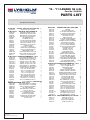
'10 - '11 CAMARO SS 6.2L
Part No. 2310160
parts list
IMPORTANT:
PART NO.
Before beginning installation, verify that all parts are included in the kit. Report any shortages or
damaged parts immediately.
DESCRIPTION
QTY
2L218-060 S/C ASY, 2300 LYS, GM LS 821/823
2L036-365-01
PULLEY, 6-RIB, 3.65, LYSHOLM
4LGE112-010 AIR INLET, ASY, CAMARO SS
7PS500-400
REDUCER, SILICONE, 5.0-4.0, BL
7R002-064
#64 SAE TYPE F SS HOSE CLAMP
7R002-080
#80 SAE TYPE F SS HOSE CLAMP
4LGE012-010
BOX, AIR INLET, 2010 CAMARO, L
7C040-008
M4-.7X8MM SCHD SS
7J250-001
1/4 WASHER, SAE, PLTD
7F250-021
1/4-20 NYLOCK NUT ZINC PLATED
7A250-053
1/4-20 X .50 BHCS TORX SECURI
8H040-400
AIR FILTER, 4" FLANGE, 12" LON
7PS400-225
BUMP SLEEVE, "4 X 2.25, BLACK
7U030-030
1/4" VACUUM HOSE
7P125-109
FTG, 1/8NPT - 1/4 BARB, AL
7P250-045P
1/4 MALE NPT X 3/8 MALE BARB N
7A250-050
1/4-20 X .50 SHCS GR8 ZINC PLT
7J006-093
6MM WASHER, PLATED
4LGE010-050
BRKT, UPPER, AIR BOX, 2010 CAM
4LGE010-060
BRKT, LOWER, AIR BOX, 2010 CAM
8A003-121
MAF, 3.8 I.D., LS LYSHOLM, BLK
4LGE116-010 DRIVE ASY,CAMARO SS, '10-'11
4LGE010-021
PLATE, TENSR, MOUNTING, LS LYS
4LGE010-031
MNTG PLT, IDLER, LS CAMARO LYS
2A017-878-10
SPACER, .875 OD X 3.221 L, ANO
2A017-750-10
SPACER, .75OD X 1.360 L, ANOD.
2A017-878-11
SPACER, .875 OD X .754 L, ANOD
2A017-875-26
SPACER, .875 OD X .404 ID X .085
4LGE017-011
SPCR, IDLER PILOT, LS CAMARO L
4LGE010-041
SUPPORT BRKT, CYL HEAD, LS CAM
4FA016-150
IDLER PULY,6RIB 3.5" FLANGED
7C080-120
M8 X 1.25 X 120 HXHD Zn PLT
7C010-040
M10 X 1.5 X 40 HXHD CL8.8 ZN
7C010-055
M10 X 1.5 X 50 HXHD CL10.9
7C010-090
M10 X 1.5 X 90 HXHD CL8.8
7C010-120
M10 X 1.50 X 120 HXHD, CL10.9
7J010-002
10mm WASHER, ZINC PLATED
2A046-073
BELT, 6 RIB X 107.32 EFFECT. L
7G010-005
NUT, PEM, M10 X 1.5, ZINC SEL
7C080-008
M8 X 1.25 X 8MM BHCS, ZINC, CL
1
1
1
1
3
1
1
2
4
4
4
1
1
3
1
1
3
3
1
1
1
1
1
1
2
3
5
1
2
1
2
3
3
4
1
2
10
1
4
1
7J312-000
5/16 FLAT WASHER-SAE44GE155-030
REMOTE W.WASHER ASSY, '10-'11 1
4GE010-080
BRKT, WSHR RESVR, 2010 CAMARO
1
4GE010-090
BRKT, REMOTE FILL, 2010 CAMARO
1
4GE055-010
TANK "A", WSHR FLUID INTEGRAL,
1
4GE055-020
CAP, THRD UNVENTED
1
4GE055-030
TANK, REMOTE FILL WSHR FLUID,
1
7A250-063
1/4-20 X .63 HHCS SS
6
7E010-050
#12 X 1/2 SHEET METAL SCREW
5
7J250-001
1/4 WASHER, SAE, PLTD
6
7P375-625
3/8 NPT X 5/8 HOSE BARB
1
7R002-010
#10 SAE TYPE F SS HOSE CLAMP
2
7R007-002
NYLON RATCHET CLAMP .90"
2
7U033-000
5/8" PCV HOSE
2
P/N: 4LGE020-010 v3.1, 2012-03-12
© 2012 Lysholm
All Rights Reserved, Intl. Copr. Secured
PART NO.
DESCRIPTION
QTY
8N107-005
WATER PUMP ASSY, 5GPM UNIV 1
5W001-002
FUSE TAP
1
5W001-032
1/4" PLASTIC WIRE LOOM
60
5W001-009
16-14GA MALE SLIDE INSULATED
1
5W001-013
14-16 GA BUTT CONN BLU INSUL
4
5W001-015
FUSE, BLADE TYPE 20 AMP
1
5W001-022
T-TAP CONN,14-16 AWG
1
5W001-024
MINI ATC FUSE TAP
1
5W001-041
12-10GA MALE SLIDE INSULATED
2
5W001-043
12-10GA X 1/4" RING TERMINAL
3
5W001-050
HARNESS, FUEL INJ PLUG W/WIRES
1
5W001-014
FUSE HOLDER 10 GA WIRE
1
7A250-050
1/4-20 X .50 SHCS GR8 ZINC PLT
2
7E010-075
#12 X 3/4" SHT METL SCRW HEX
3
7F250-021
1/4-20 NYLOCK NUT ZINC PLATED
2
7J250-001
1/4 WASHER, SAE, PLTD
2
7U100-044
TIE WRAP, 4" NYLON
4
7U100-055
TIE WRAP, 7.5" NYLON
6
8F001-403
PUMP, WATER, BOSCH
1
8F101-320
WATER PUMP RELAY ASSY
1
8N010-060
BRACKET, BOSCH WATER PUMP
1
5W001-011
16-14 GA RING TERM .26" HOLE
2
5W001-017
12-10GA X 3/8" RING TERMINAL
1
5W001-037
12-10 GA BUTT CON, SHRNK TYPE
2
5W001-040
12-10GA FEMALE SLIDE INSULATED
2
5W001-007
3/16" HEAT-SHRINK TUBING
0.83333
5W001-025
FEM SLIDE,INSUL,MINI,22-16AWG
1
4LGE155-010SUPPORT ASY,CAMARO SS, '10-'11 1
4LGE010-070
SHIELD, HEAT, IGN COIL, 2010 C
1
7C060-020
M6 X 10 X 20MM HHCS ZN
1
7J006-093
6MM WASHER, PLATED
6
5W001-030
1 1/2" HEAT SHRINK
1
5W001-082
SLEEVE, FLEX BRAID .75" NOM
4
5W001-090
HARNESS, ETC EXT, CAMARO SS
1
5W001-091
HARNESS, MAF/IAT BRKOUT, CAMAR
1
4LGE014-010
RELOCATION ASSY, HTR HOSE , CA
1
4LGE010-080
COVER, COIL BRKT, PASS, CAMAR
1
7U031-018
5/16 EFI FUEL HSE HI-PSR
3.5
7U031-018
5/16 EFI FUEL HSE HI-PSR
1.8
7R004-003
STEPLESS CLAMP, 145-70
4
4GR110-110
ASSY, DAMPER PIN, LS1-LS2-LS6
1
7A250-050
1/4-20 X 50 SHCS GR8 ZINC PLT
3
7J250-001
1/4 WASHER, SAE, PLTD
6
7F250-021
1/4-20 NYLOCK NUT ZINC PLATED
3
7C060-028
STANDOFF, M6 X 10 M/F, 1175L
2
7C060-027
M6 X 10 X 25 BUTN HD ZN PLT
2
7C060-031
M6 X 10 X 30 BUTN HD ZN PLT
2
7C060-017
M6 X 10 X 16 BUTN HD ZN PLT
2
7J012-009
WASHER, #12 INT TOOTH LOCK
2
2A017-501-175
SPACER, 50 OD X 25 ID X 175
2
7P312-020
5/16 FORD 90º FUEL FTG PLSTC
2
4LGE145-010
FUEL FEED HOSE ASY, LYSH 62L
1
4GR110-110 ASSY, DAMPER PIN, LS1-LS2-LS6 1
4GR010-110
GUIDE, DWL PIN IST, C5
1
7C016-010
BOLT, OEM LS1, M16-2.0
1
7C016-100
BOLT,M16-2.0X100MM SHCS
1
7U250-019
DOWEL PIN,1/4D X 1/2L
1
v
'10 - '11 CAMARO SS 6.2L
Part No. 2310160
parts list (cont'd)
IMPORTANT:
PART NO.
Before beginning installation, verify that all parts are included in the kit. Report any shortages or
damaged parts immediately.
DESCRIPTION
QTY
PART NO.
DESCRIPTION
QTY
8N106-180 WATER COOLER ASSY, LYSH CAM SS1
8N006-020
WATER COOLER, DUAL PASS
1
8N010-380
BRKT, PASS, HEAT EXCHGR, 2010
1
8N010-390
BRKT, DRVR, HEAT EXCHGR, 2010
1
7R007-001
NYLON RATCHET CLAMP 1-1/8"
2
7U038-012
HOSE, 3/4 DIA 90º, 4 X 12 LEGS
2
7J250-001
1/4 WASHER, SAE, PLTD
4
7A250-051
1/4-20 X .50 HHCS GR5 ZINC PLT
4
8N105-210 WATER TANK ASSY, LYSH CAM SS 1
7U038-000
3/4" HEATER HOSE
10
7R007-001
NYLON RATCHET CLAMP 1-1/8"
12
7U038-012
HOSE, 3/4 DIA 90º, 4 X 12 LEGS
1
7P375-075
3/4" HOSE BARB UNION, BRASS
3
7P500-075
1/2NPT X 3/4 HOSE FIT STRT NIC
1
7P500-034
1/2NPT X 3/4 BARB 90º, NICKEL
1
8N056-060
SURGE TANK, PLASTIC
1
8N055-050
PLASTIC CAP, SURGE TANK
1
8N010-400
BRKT, MTG, SURGE TANK, '10 CAM
1
8N055-030
TANK, WATER, TRIANGLE SHAPE
1
4CK010-060
BRKT,WATER TANK MTG, JGC
1
7E010-075
#12 X 3/4" SHT METL SCRW HEX
4
7J250-001
1/4 WASHER, SAE, PLTD
9
7P500-026
1/2NPT X 3/4 BARB 90º BRASS
2
7A250-050
1/4-20 X .50 SHCS GR8 ZINC PLT
2
7A250-051
1/4-20 X .50 HHCS GR5 ZINC PLT
4
8N010-410
BRKT, MTG, BOSCH H20 PMP, 10 C
1
7A250-039
1/4-20 X .375 BHCS
2
009028
S/C LUBE, LYSHOLM 1600/2300
1
5A003-060
TUNER, SCT, GM
1
vi
P/N: 4LGE020-010 v3.1, 2012-03-12
© 2012 Lysholm
All Rights Reserved, Intl. Copr. Secured
'10 - '11 CAMARO SS (TUNER KIT)
Part No. 2310180
parts list
IMPORTANT:
PART NO.
Before beginning installation, verify that all parts are included in the kit. Report any shortages or
damaged parts immediately.
DESCRIPTION
QTY
2L218-070 S/C ASY, TUNER 2300 LYS,LS 821/8231
2L036-365-01
PULLEY, 6-RIB, 3.65, LYSHOLM
1
4LGE112-010 INLET AIR, ASY, CAMARO SS 1
7PS500-400
REDUCER, SILICONE, 5.0-4.0, BL
1
7R002-064
#64 SAE TYPE F SS HOSE CLAMP
3
7R002-080
#80 SAE TYPE F SS HOSE CLAMP
1
4LGE012-010
BOX, AIR INLET, 2010 CAMARO, L
1
7C040-008
M4-.7X8MM SCHD SS
2
7J250-001
1/4 WASHER, SAE, PLTD
4
7F250-021
1/4-20 NYLOCK NUT ZINC PLATED
4
7A250-053
1/4-20 X .50 BHCS TORX SECURI
4
8H040-400
AIR FILTER, 4" FLANGE, 12" LON
1
7PS400-225
BUMP SLEEVE, "4 X 2.25, BLACK
1
7U030-030
1/4" VACUUM HOSE
3
7P125-109
FTG, 1/8NPT - 1/4 BARB, AL
1
7P250-045P
1/4 MALE NPT X 3/8 MALE BARB N
1
7A250-050
1/4-20 X .50 SHCS GR8 ZINC PLT
3
7J006-093
6MM WASHER, PLATED
3
4LGE010-050
BRKT, UPPER, AIR BOX, 2010 CAM
1
4LGE010-060
BRKT, LOWER, AIR BOX, 2010 CAM
1
8A003-121
MAF, 3.8 I.D., LS LYSHOLM, BLK
1
4LGE116-010 DRIVE ASY,CAMARO SS, '10-'11
1
4LGE010-021
PLATE, TENSR, MOUNTING, LS LYS
1
4LGE010-031
MNTG PLT, IDLER, LS CAMARO LYS
1
2A017-878-10
SPACER, .875 OD X 3.221 L, ANO
2
2A017-750-10
SPACER, .75OD X 1.360 L, ANOD.
3
2A017-878-11
SPACER, .875 OD X .754 L, ANOD
5
2A017-875-26
SPACER, .875 OD X .404 ID X .085
1
4LGE017-011
SPCR, IDLER PILOT, LS CAMARO L
2
4LGE010-041
SUPPORT BRKT, CYL HEAD, LS CAM
1
4FA016-150
IDLER PULY,6RIB 3.5" FLANGED
2
7C080-120
M8 X 1.25 X 120 HXHD Zn PLT
3
7C010-040
M10 X 1.5 X 40 HXHD CL8.8 ZN
3
7C010-055
M10 X 1.5 X 50 HXHD CL10.9
4
7C010-090
M10 X 1.5 X 90 HXHD CL8.8
1
7C010-120
M10 X 1.50 X 120 HXHD, CL10.9
2
7J010-002
10mm WASHER, ZINC PLATED
10
2A046-073
BELT, 6 RIB X 107.32 EFFECT. L
1
7G010-005
NUT, PEM, M10 X 1.5, ZINC SEL
4
7C080-008
M8 X 1.25 X 8MM BHCS, ZINC, CL
1
7J312-000
5/16 FLAT WASHER-SAE
4
4GE155-030 REMOTE W.WASHER ASSY, '10-'11 1
4GE010-080
BRKT, WSHR RESVR, 2010 CAMARO
1
4GE010-090
BRKT, REMOTE FILL, 2010 CAMARO
1
4GE055-010
TANK "A", WSHR FLUID INTEGRAL,
1
4GE055-020
CAP, THRD UNVENTED 1
4GE055-030
TANK, REMOTE FILL WSHR FLUID,
1
7A250-063
1/4-20 X .63 HHCS SS
6
7E010-050
#12 X 1/2 SHEET METAL SCREW
5
7J250-001
1/4 WASHER, SAE, PLTD
6
7P375-625
3/8 NPT X 5/8 HOSE BARB
1
7R002-010
#10 SAE TYPE F SS HOSE CLAMP
2
7R007-002
NYLON RATCHET CLAMP .90"
2
7U033-000
5/8" PCV HOSE
2
P/N: 4LGE020-010 v3.1, 2012-03-12
© 2012 Lysholm
All Rights Reserved, Intl. Copr. Secured
PART NO.
DESCRIPTION
QTY
8N107-005
WATER PUMP ASSY, 5GPM UNIV 1
5W001-002
FUSE TAP
1
5W001-032
1/4" PLASTIC WIRE LOOM
60
5W001-009
16-14GA MALE SLIDE INSULATED
1
5W001-013
14-16 GA BUTT CONN BLU INSUL
4
5W001-015
FUSE, BLADE TYPE 20 AMP
1
5W001-022
T-TAP CONN,14-16 AWG
1
5W001-024
MINI ATC FUSE TAP
1
5W001-041
12-10GA MALE SLIDE INSULATED
2
5W001-043
12-10GA X 1/4" RING TERMINAL
3
5W001-050
HARNESS, FUEL INJ PLUG W/WIRES
1
5W001-014
FUSE HOLDER 10 GA WIRE
1
7A250-050
1/4-20 X .50 SHCS GR8 ZINC PLT
2
7E010-075
#12 X 3/4" SHT METL SCRW HEX
3
7F250-021
1/4-20 NYLOCK NUT ZINC PLATED
2
7J250-001
1/4 WASHER, SAE, PLTD
2
7U100-044
TIE WRAP, 4" NYLON
4
7U100-055
TIE WRAP, 7.5" NYLON
6
8F001-403
PUMP, WATER, BOSCH
1
8F101-320
WATER PUMP RELAY ASSY
1
8N010-060
BRACKET, BOSCH WATER PUMP
1
5W001-011
16-14 GA RING TERM .26" HOLE
2
5W001-017
12-10GA X 3/8" RING TERMINAL
1
5W001-037
12-10 GA BUTT CON, SHRNK TYPE
2
5W001-040
12-10GA FEMALE SLIDE INSULATED
2
5W001-007
3/16" HEAT-SHRINK TUBING
0.83333
5W001-025
FEM SLIDE,INSUL,MINI,22-16AWG
1
4LGE155-010SUPPORT ASY,CAMARO SS, '10-'11 1
4LGE010-070
SHIELD, HEAT, IGN COIL, 2010 C
1
7C060-020
M6 X 10 X 20MM HHCS ZN
1
7J006-093
6MM WASHER, PLATED
6
5W001-030
1 1/2" HEAT SHRINK
1
5W001-082
SLEEVE, FLEX BRAID .75" NOM
4
5W001-090
HARNESS, ETC EXT, CAMARO SS
1
5W001-091
HARNESS, MAF/IAT BRKOUT, CAMAR
1
4LGE014-010
RELOCATION ASSY, HTR HOSE , CA
1
4LGE010-080
COVER, COIL BRKT, PASS, CAMAR
1
7U031-018
5/16 EFI FUEL HSE HI-PSR
3.5
7U031-018
5/16 EFI FUEL HSE HI-PSR
1.8
7R004-003
STEPLESS CLAMP, 145-70
4
4GR110-110
ASSY, DAMPER PIN, LS1-LS2-LS6
1
7A250-050
1/4-20 X 50 SHCS GR8 ZINC PLT
3
7J250-001
1/4 WASHER, SAE, PLTD
6
7F250-021
1/4-20 NYLOCK NUT ZINC PLATED
3
7C060-028
STANDOFF, M6 X 10 M/F, 1175L
2
7C060-027
M6 X 10 X 25 BUTN HD ZN PLT
2
7C060-031
M6 X 10 X 30 BUTN HD ZN PLT
2
7C060-017
M6 X 10 X 16 BUTN HD ZN PLT
2
7J012-009
WASHER, #12 INT TOOTH LOCK
2
2A017-501-175
SPACER, 50 OD X 25 ID X 175
2
7P312-020
5/16 FORD 90º FUEL FTG PLSTC
2
4LGE145-010
FUEL FEED HOSE ASY, LYSH 62L
1
4GR110-110 ASSY, DAMPER PIN, LS1-LS2-LS6 1
4GR010-110
GUIDE, DWL PIN IST, C5
1
7C016-010
BOLT, OEM LS1, M16-2.0
1
7C016-100
BOLT,M16-2.0X100MM SHCS
1
7U250-019
DOWEL PIN,1/4D X 1/2L
1
vii
'10 - '11 CAMARO SS (TUNER KIT)
Part No. 2310180
parts list
IMPORTANT:
PART NO.
(cont'd)
Before beginning installation, verify that all parts are included in the kit. Report any shortages or
damaged parts immediately.
DESCRIPTION
QTY
PART NO.
DESCRIPTION
QTY
8N106-180 WATER COOLER ASSY, LYSH CAM SS1
8N006-020
WATER COOLER, DUAL PASS
1
8N010-380
BRKT, PASS, HEAT EXCHGR, 2010
1
8N010-390
BRKT, DRVR, HEAT EXCHGR, 2010
1
7R007-001
NYLON RATCHET CLAMP 1-1/8"
2
7U038-012
HOSE, 3/4 DIA 90º, 4 X 12 LEGS
2
7J250-001
1/4 WASHER, SAE, PLTD
4
7A250-051
1/4-20 X .50 HHCS GR5 ZINC PLT
4
8N105-210 WATER TANK ASSY, LYSH CAM SS 1
7U038-000
3/4" HEATER HOSE
10
7R007-001
NYLON RATCHET CLAMP 1-1/8"
12
7U038-012
HOSE, 3/4 DIA 90º, 4 X 12 LEGS
1
7P375-075
3/4" HOSE BARB UNION, BRASS
3
7P500-075
1/2NPT X 3/4 HOSE FIT STRT NIC
1
7P500-034
1/2NPT X 3/4 BARB 90º, NICKEL
1
8N056-060
SURGE TANK, PLASTIC
1
8N055-050
PLASTIC CAP, SURGE TANK
1
8N010-400
BRKT, MTG, SURGE TANK, '10 CAM
1
8N055-030
TANK, WATER, TRIANGLE SHAPE
1
4CK010-060
BRKT,WATER TANK MTG, JGC
1
7E010-075
#12 X 3/4" SHT METL SCRW HEX
4
7J250-001
1/4 WASHER, SAE, PLTD
9
7P500-026
1/2NPT X 3/4 BARB 90º BRASS
2
7A250-050
1/4-20 X .50 SHCS GR8 ZINC PLT
2
7A250-051
1/4-20 X .50 HHCS GR5 ZINC PLT
4
8N010-410
BRKT, MTG, BOSCH H20 PMP, 10 C
1
7A250-039
1/4-20 X .375 BHCS
2
009028
S/C LUBE, LYSHOLM 1600/2300
1
viii
P/N: 4LGE020-010 v3.1, 2012-03-12
© 2012 Lysholm
All Rights Reserved, Intl. Copr. Secured
P/N: 4LGE020-010 v3.1, 2012-03-12
© 2012 Lysholm
All Rights Reserved, Intl. Copr. Secured
ix
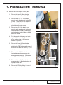
1. PREPaRATION / Removal
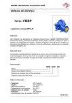
A. Remove the Front Bumper Cover (FBC):
1. Remove the two (2) 10mm-headed
screws from the bottom of the FBC.
2. Remove three (3) T20 Torx screws
securing each splash guard to the FBC
(6 total). These screws are located in
the wheel wells just forward of the front
wheels along the outer edge.
3. Remove two (2) of the plastic pins
securing each splash guard to the inner
fender structure (4 total). One is adjacent to the strut and the other is directly
above the wheel.
Fig 1A
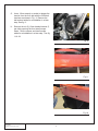
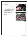
4. Pull the splash shield away so it rests
against the tire, revealing the fasteners
at the leading edge of the fender as
shown in Figure 1A.
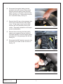
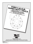
5. Remove the four (4) 10mm-headed
screws and one (1) 7mm-headed screw
attaching the FBC to the leading edge of
the fender on each side (See fig. 1B, LH
side shown).
10MM SCREWS
6. Disconnect the FBC electrical connector
located between the passenger side
driving light and headlight. Access the
connector via the wheel well.
7MM SCREW
7. Remove the two (2) 10mm-headed
screws and six (6) plastic pins along the
top edge of the FBC.
8. Remove the FBC by sliding it forward
and away from the car.
Fig 1B
1
P/N: 4LGE020-010 v3.1, 2012-03-12
© 2012 Lysholm
All Rights Reserved, Intl. Copr. Secured
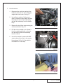
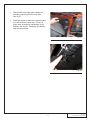
B. Disconnect the negative battery terminal
(located in the trunk) using a 10mm socket.
Remove the trunk carpet, loosen the large
plastic wing nut in the center of the floor and
lift the trunk floor out. Remove the tire repair
kit to reveal the battery. See fig 1C.
C. Remove the oil fill cap on the passenger side
valve cover to allow removal of the engine
cover. Lift the engine cover from the front
and then pull it out toward the front of the
vehicle. Temporarily reinstall the oil fill cap to
prevent contamination.
Fig 1C
D. Remove the nut securing the black plastic
engine cover support to the rear section of
the intake manifold. Pivot the support upward
and snap it off of the passenger side fuel rail.
See fig 1D.
E. Disconnect the MAF electrical connector from
the meter in the intake air tube as shown in
See fig. 1E.
Fig 1D
Fig 1E
P/N: 4LGE020-010 v3.1, 2012-03-12
© 2012 Lysholm
All Rights Reserved, Intl. Copr. Secured
2
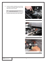
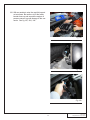
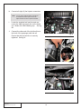
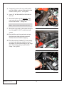
F. Air inlet removal
1. Disconnect the vent line running to the
intake air tube from the front of the passenger side valve cover. See fig 1F.
2. Use an 8mm socket or flat-tip screwdriver to loosen the hose clamp securing
the intake air tube to the throttle body
and pull the tube away from the throttle
body.
3. Remove the two 10mm nuts securing the
air box as shown in Fig. 1G.
Fig 1F
4. Pull the air box straight up to release it
from the retaining grommet on the bottom and remove the entire assembly
from the vehicle.
10MM NUTS
5. Use a 7mm socket to remove the MAF
sensor element from the air box assembly as shown in Fig. 1H. Set aside for
reinstallation in a later step
Fig 1G
Fig 1H
3
P/N: 4LGE020-010 v3.1, 2012-03-12
© 2012 Lysholm
All Rights Reserved, Intl. Copr. Secured
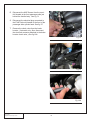
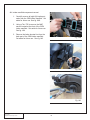
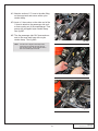
G. Use a 15mm wrench or socket to release the
tension from the 6-rib belt with the OEM belt
tensioner as shown in Fig. 1I. Remove the
belt and set aside for reinstallation in a later
step. See fig 1I.
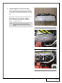
H. Remove the six (6) 13mm-headed screws (3
per side) securing the front steel bumper
beam. Set the screws and steel bumper
aside for reinstallation in a later step. See fig
1J & 1K.
Fig 1I
Fig 1J
Fig 1K
P/N: 4LGE020-010 v3.1, 2012-03-12
© 2012 Lysholm
All Rights Reserved, Intl. Copr. Secured
4
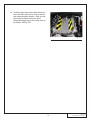
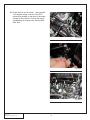
I.
Remove the driver side upper radiator air
shroud by removing the two body clips.
See fig 1L.
J. Drain the engine coolant into a clean container to be reused in a later step. There is a
drain valve at the driver side bottom of the
radiator. See fig 1M. Removing the radiator
cap will improve flow.
Fig 1L
Fig 1M
5
P/N: 4LGE020-010 v3.1, 2012-03-12
© 2012 Lysholm
All Rights Reserved, Intl. Copr. Secured
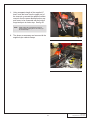
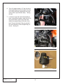
K. Once the coolant is drained, remove the factory clamps securing the heater hoses at the
water pump and the firewall.
NOTE: It may be easier to remove the clamps at the firewall after intake manifold removal.
L. Set hoses aside as they will not be reused.
Fig 1N
Fig 1O
Fig 1P
P/N: 4LGE020-010 v3.1, 2012-03-12
© 2012 Lysholm
All Rights Reserved, Intl. Copr. Secured
6
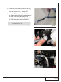
M. Washer reservior removal
1. Locate the windshield washer reservoir
(under the driver side headlight) and disconnect the electrical connector from the
pump.
2. Drain the reservoir by removing the
pump from its grommet and retaining
saddle and catching the fluid in a large,
clean open container or funnel as shown
in Fig 1Q. Keep the fluid for later reuse.
3. Remove the washer hose from the 90º
fitting near the pump and free it from the
attachment points on the reservoir.
4. Remove the grommet from the reservoir
and retain for later use.
Fig 1Q
5. Remove the three (3) 13mm-headed
screws mounting the windshield washer
reservoir and set the reservoir aside.
See fig 1R. It will be replaced in a later
step. Set one (1) of the 13mm headed
screws aside for future use.
Fig 1R
7
P/N: 4LGE020-010 v3.1, 2012-03-12
© 2012 Lysholm
All Rights Reserved, Intl. Copr. Secured
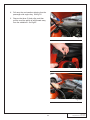
N. Disconnect the driver-side main coil bracket
harness by releasing the green clip lock and
separating the connector by lifting the connector tab. See fig 1S, 1T.
O. Disconnect the four (4) driver-side spark plug
wires from the bottom of each ignition coil.
See fig 1U.
Fig 1S
Fig 1T
Fig 1U
P/N: 4LGE020-010 v3.1, 2012-03-12
© 2012 Lysholm
All Rights Reserved, Intl. Copr. Secured
8
P. Remove the five (5) fasteners securing the
driver-side coil bracket to the valve cover.
Remove coil pack assembly and set aside for
future use. See fig 1V, 1W.
Q. Remove the engine cover pedestal fastener
from the driver-side valve cover and set aside
for future use. See fig 1X.
Fig 1V
Fig 1W
Fig 1X
9
P/N: 4LGE020-010 v3.1, 2012-03-12
© 2012 Lysholm
All Rights Reserved, Intl. Copr. Secured
R. Disconnect the MAP Sensor from the manifold located at the front passenger-side just
behind the throttle body. See fig 1Y.
S. Disconnect the electrical plug connected to
the EVAP Solenoid located to the front of the
passenger-side cylinder head. See fig 1Z.
T. Remove the check valve from the brake
booster. (Automatic only: Also, disconnect
the electrical connector attached to the brake
booster check valve.) See fig 1AA.
Fig 1Y
Fig 1Z
Fig 1AA
P/N: 4LGE020-010 v3.1, 2012-03-12
© 2012 Lysholm
All Rights Reserved, Intl. Copr. Secured
10
U. Disconnect both ends of the EVAP Line that
runs from the EVAP solenoid to the intake
manifold, just behind the driver-side of the
throttle body. Set aside for future use. See fig
1AB & 1AC.
V. Disconnect the electrical connector attached
to the passenger-side of the throttle body.
See fig 1AD.
Fig 1AB
Fig 1AC
Fig 1AD
11
P/N: 4LGE020-010 v3.1, 2012-03-12
© 2012 Lysholm
All Rights Reserved, Intl. Copr. Secured
W. Throttle body removal
1. Remove the four (4) 10mm headed
screws securing the throttle body to the
manifold. See fig 1AE.
2. Remove the throttle body and green
throttle body seal from intake manifold.
Set aside throttle body, hardware and
seal for future use. See fig 1AF.
X
Disconnect both ends of the the breather line
that attaches to the passenger side of the
intake manifold just behind the throttle body.
See fig 1AG.
Fig 1AE
1. (Manual transmission) Attach to lifter valley cover.
2. (Automatic transmission) Attach to driverside valve cover.
Fig 1AF
Fig 1AG
P/N: 4LGE020-010 v3.1, 2012-03-12
© 2012 Lysholm
All Rights Reserved, Intl. Copr. Secured
12
Y. Remove the two (2) 15mm headed screws
securing the belt tensioner to the water pump
just in front of the passenger cylinder head.
Remove and set tensioner aside for future
use. See fig 1AH, 1AI.
Z. Remove 15mm headed screw securing EVAP
solenoid bracket to front of the passenger
side cylinder head. Set bracket aside for
future use. See fig 1AJ.
Fig 1AH
Fig 1AI
Fig 1AJ
13
P/N: 4LGE020-010 v3.1, 2012-03-12
© 2012 Lysholm
All Rights Reserved, Intl. Copr. Secured
AA.Remove the 15mm headed nut securing the
engine ground wire to the stud mounted on
the front of the passenger side cylinder head,
near the exhaust manifold. See fig 1AK, 1AL.
AB.Remove the 15mm headed engine ground
stud from the passenger side cylinder head
and save for future use. See fig 1AM.
Fig 1AK
Fig 1AL
Fig 1AM
P/N: 4LGE020-010 v3.1, 2012-03-12
© 2012 Lysholm
All Rights Reserved, Intl. Copr. Secured
14
NOTE: Caution should be used when working on the fuel
system. Fuel may be under high pressure. Fuel system work should be performed in a well ventilated
area free of any possible ignition source. It is recom
mended that you have a fire extinguisher nearby.
AC.Remove the fuel tank cap. Relieve the fuel
system pressure at the fuel rail by carefully
depressing the schrader valve. Use a rag to
cover the valve to avoid fuel spray. See fig
1AN.
Fig 1AN
AD.Disconnect the eight (8) fuel injector wiring
clips from the injectors. See fig 1AO.
AE.Remove the fuel feed line assembly as follows:
1. Remove the safety clip from the 3/8 fuel
feed line located on the side of the passenger strut tower below the ABS module.
2 Disconnect the 3/8 fuel feed line and the
5/16 EVAP Quick disconnect fittings from
the feed lines on the side of the passenger strut tower using the appropriate disconnect tools.
Fig 1AO
3. Remove the nut securing the fuel feed
line to the front passenger side fuel rail
stud.
4. Remove the safety clip and disconnect
the fuel feed line where it attaches to the
fuel rail assembly on the manifold using
the appropriate disconnect tool. Take
care to absorb any fuel spillage.
Fig 1AP
15
P/N: 4LGE020-010 v3.1, 2012-03-12
© 2012 Lysholm
All Rights Reserved, Intl. Copr. Secured
AF. Remove the eight (8) forward most of the ten
(10) 8mm headed screws securing the intake
manifold to the cylinder heads. To simplify
removal of the intake manifold, use tape to
temporarily hold the rear two screws in an
elevated position. See fig 1AS.
Fig 1AQ
Fig 1AR
Fig 1AS
P/N: 4LGE020-010 v3.1, 2012-03-12
© 2012 Lysholm
All Rights Reserved, Intl. Copr. Secured
16
AG.With an assistant, raise the manifold up and
out as shown. Be cautious to lift the brake
booster hose up and around the engine oil
pressure sensor to avoid damage to the connector. See fig 1AT, 1AU, 1AV.
Fig 1AT
Fig 1AU
Fig 1AV
17
P/N: 4LGE020-010 v3.1, 2012-03-12
© 2012 Lysholm
All Rights Reserved, Intl. Copr. Secured
AH.Intake manifold component removal
1. Carefully remove all eight (8) intake port
seals from the OEM intake manifold. Set
aside for future use. See fig 1AW.
2. Using a Torx T25 to remove the MAP
sensor located at the front of the OEM
intake manifold. Set aside for future use.
See fig 1AX.
3. Remove the brake booster line from the
back port of the OEM intake manifold.
Set aside for future use. See fig 1AY.
Fig 1AW
Fig 1AX
Fig 1AY
P/N: 4LGE020-010 v3.1, 2012-03-12
© 2012 Lysholm
All Rights Reserved, Intl. Copr. Secured
18
AI. Carefully clean the cylinder head mating surfaces and lifter valley cover using a vacuum
and carburetor/brake cleaner. Wipe dry and
ensure that no debris enters the ports.
Temporarily apply tape to the intake ports on
the heads. See fig 1AZ.
Fig 1AZ
19
P/N: 4LGE020-010 v3.1, 2012-03-12
© 2012 Lysholm
All Rights Reserved, Intl. Copr. Secured
P/N: 4LGE020-010 v3.1, 2012-03-12
© 2012 Lysholm
All Rights Reserved, Intl. Copr. Secured
20
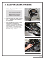
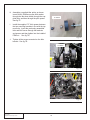
2. Damper/crank pinning
A. Lock the engine from rotating and remove the
OEM damper pulley bolt.
NOTE: Automatic transmission cars can lock the engine
through the trans inspection cover with a 15/16"
open end wrench to one of the torque converter
mounting bosses on the flex plate.
Manual transmission cars place car in 6th gear
with wheels on the ground and apply parking
brake.
B. Remove the factory crank damper bolt using a
15/16" or 24mm socket. Set bolt aside as it
will not be reused.
Fig 2A
C. Install the supplied drill guide with the raised
section piloting in the damper bore.
Temporarily secure in place by installing the
supplied socket head cap screw. Do not overtighten the screw as it may distort the drill
guide (its purpose is just to hold the guide in
place while drilling). See fig 2C.
Fig 2B
Fig 2C
21
P/N: 4LGE020-010 v3.1, 2012-03-12
© 2012 Lysholm
All Rights Reserved, Intl. Copr. Secured
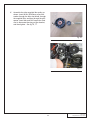
D. Mark a ¼” drill bit with tape or use a drill stop
at a point 1-3/16” (~1.2") minimum from the
tip of the drill. See fig 2D.
E. Using an angle drill or small drill motor, drill
into the crankshaft/damper hub assembly
through the bushing in the drill guide, taking
care to keep the tool perpendicular to the
damper. Stop when the tape reaches the front
of the drill guide. This should yield a hole
depth of at least ½”.
F. Remove the socket head cap screw and drill
guide. Carefully remove any metal chips from
the area with compressed air. The drilled 1/4"
hole should appear as in Fig. 2E.
Fig 2D
G. Install the supplied Ø1/4" x 1/2" long dowel
pin into the drilled hole with the chamfered
end pointed toward the front of the vehicle.
See fig 2F.
H. Verify that the dowel pin is recessed slightly
from the machined portion of the damper
face.
Fig 2E
Fig 2F
P/N: 4LGE020-010 v3.1, 2012-03-12
© 2012 Lysholm
All Rights Reserved, Intl. Copr. Secured
22
I.
Install the supplied new OEM damper retaining bolt as follows:
1. Lightly coat the threads of the new
retaining bolt with red thread locker.
Install and torque to 37 ft-lb. See fig 2G.
2. Using a ½” drive or larger breaker bar,
tighten the retaining bolt an additional
120º or torque to 250 ft-lb. See fig 2H.
J. Automatic Transmission: “Unlock” the
engine from turning by removing the previously-installed wrench holding the flex plate
and replace the inspection cover.
Fig 2G
Manual Transmission: Place the transmission in Neutral.
Fig 2H
23
P/N: 4LGE020-010 v3.1, 2012-03-12
© 2012 Lysholm
All Rights Reserved, Intl. Copr. Secured
P/N: 4LGE020-010 v3.1, 2012-03-12
© 2012 Lysholm
All Rights Reserved, Intl. Copr. Secured
24
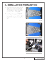
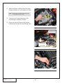
3. INSTALLATION PREPaRATION
A. Using a criss cross pattern starting from the
center, remove one at a time the ten (10)
13mm headed screws securing the valley
cover plate. Replace with the supplied M8
button head screws. See fig 3A, 3B.
B. Install the previously removed OEM MAP
sensor on to the front of the supercharger
lower manifold, and secure with the supplied
M6x1.0x16MM using a 4mm Allen key. See
fig 3C.
Fig 3A
Fig 3B
Fig 3C
25
P/N: 4LGE020-010 v3.1, 2012-03-12
© 2012 Lysholm
All Rights Reserved, Intl. Copr. Secured
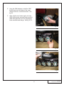
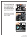
C. Install the supplied replacement heater coolant pipe assembly to heater core and water
pump with supplied clamps and elbows as
shown. See fig 3D, 3E.
D. Apply a light coat of clean engine oil to the
previously removed OEM throttle body seal
and install it into the flange of the supercharger inlet duct. See fig 3F.
Fig 3D
Fig 3E
Fig 3F
P/N: 4LGE020-010 v3.1, 2012-03-12
© 2012 Lysholm
All Rights Reserved, Intl. Copr. Secured
26
E. Using the OEM hardware, install the OEM
throttle body onto the flange of the supercharger inlet duct, oriented as shown. See
fig 3G.
F. Apply a light coat of clean engine oil to the
eight (8) previously removed intake manifold
seals and install them into the supercharger
lower manifold intake flange. See fig 3H, 3I.
Fig 3G
Fig 3H
Fig 3I
27
P/N: 4LGE020-010 v3.1, 2012-03-12
© 2012 Lysholm
All Rights Reserved, Intl. Copr. Secured
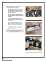
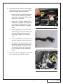
G. Locate the previously removed coil pack
assembly and modify as follows:
1. Unclip the wiring harness conduit from
the coil bracket. Removing the ignition
coil adjacent to the main plug will aid in
removal. See fig 3J.
2. Locate the supplied coil bracket relocation heat shield and place on coil bracket
as shown.
3. Transfer the three (3) holes from the
relocation heat shield onto the coil bracket. See fig 3K.
Fig 3J
4. Using a 5/16” drill bit, drill through the
three (3) marked locations on the coil
bracket. The main connector plug may
need to be removed to avoid damage
during drilling. Remove burrs/sharp
edges. See fig 3L.
NOTE: Use of a sharp drill and proper lubrication will aid in
drilling through the steel OEM bracket.
Fig 3K
Fig 3L
P/N: 4LGE020-010 v3.1, 2012-03-12
© 2012 Lysholm
All Rights Reserved, Intl. Copr. Secured
28
H. Using the supplied ¼-20x.5 screws with
washers, attach the relocation heat shield to
the coil bracket assembly as shown using the
¼-20 nylock nuts on the bottom side. See fig
3M.
I.
Install the relocation bracket assembly to the
driver side valve cover using a supplied
M6x1.0x20mm screw and two (2) factory
screws. See fig 3N, 3O.
NOTE: Slight adjustment of the factory A/C line may be
required for adequate clearance around the spark
plug wires.
Fig3M
Fig 3N
Fig 3O
29
P/N: 4LGE020-010 v3.1, 2012-03-12
© 2012 Lysholm
All Rights Reserved, Intl. Copr. Secured
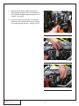
J. Reconnect the factory spark plug wires to
their respective ignition coil. You should hear
two (2) distinct clicks ensuring a positive connection. See fig 3P.
K. Reconnect the driver-side main coil bracket
harness at the connector and secure connection with the green clip lock. See fig 3Q, 3R.
Fig 3P
Fig 3Q
Fig 3R
P/N: 4LGE020-010 v3.1, 2012-03-12
© 2012 Lysholm
All Rights Reserved, Intl. Copr. Secured
30
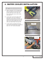
4. Water cooler INSTALLATION
NOTE: Refer to fig 4T for general CAC layout and hose routing.
A. Attach a supplied 4"x12" 90º molded rubber
hose to the upper port of the water cooler
pointing uphill back into the engine bay.
Secure with supplied nylon ratchet clamp.
See fig 4B, 4C.
B. Locate another 4"x12" 90º molded rubber
hose and trim 1.50” from the short leg.
Discard the trimmed portion of the hose and
attach the short leg to the bottom port of the
water cooler, facing straight down. Secure
with nylon ratchet clamp. See fig 4A, 4B.
Fig 4A
UPPER PORT
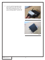
C. Loosely attach the supplied left and right
water cooler mounting brackets using the hex
head ¼-20 x 0.5” screws with washers.
Fig 4B
UPPER PORT
Fig 4C
31
P/N: 4LGE020-010 v3.1, 2012-03-12
© 2012 Lysholm
All Rights Reserved, Intl. Copr. Secured
D. While lining up each bracket with the front
bumper mounting holes, re-install the front
metal bumper beam with factory hardware,
sandwiching the water cooler support brackets in between. Tighten all six (6) factory fasteners at this time. See fig 4D, 4E, 4F.
Fig 4D
Fig 4E
Fig 4F
P/N: 4LGE020-010 v3.1, 2012-03-12
© 2012 Lysholm
All Rights Reserved, Intl. Copr. Secured
32
E. Adjust the height of the water cooler so that it
is parallel to, and suspended above the lower
support rail. Tighten the ¼-20 x 0.5” hardware. See fig 4G, 4H, 4I.
Fig 4G
Fig 4H
Fig 4I
33
P/N: 4LGE020-010 v3.1, 2012-03-12
© 2012 Lysholm
All Rights Reserved, Intl. Copr. Secured
F. Locate the supplied triangle shaped water
reservoir and two (2) ½ NPT 90º elbow fittings, and then assemble as shown. Use
¼-20x.5 screws with washers to secure the
reservoir mounting bracket. See fig 4J, 4K.
Fig 4J
Fig 4K
P/N: 4LGE020-010 v3.1, 2012-03-12
© 2012 Lysholm
All Rights Reserved, Intl. Copr. Secured
34
G. Position reservoir assembly on the passenger
side frame seam in approximate position
shown. Mark the mounting bracket hole locations and drill with an 11/64” drill bit. See fig
4L, 4M.
H. Using two (2) #12 sheet metal screws, attach
the reservoir to the frame rail. See fig 4N.
Fig 4L
Fig 4M
Fig 4N
35
P/N: 4LGE020-010 v3.1, 2012-03-12
© 2012 Lysholm
All Rights Reserved, Intl. Copr. Secured
I.
Locate a long length of supplied ¾” hose and
route the hose from the bottom port of the
previously installed reservoir up and over the
lower radiator core support and then across
to the driver side to be connected with the
water pump at a later step. See fig 4O, 4P,
4Q.
Fig 4O
Fig 4P
Fig 4Q
P/N: 4LGE020-010 v3.1, 2012-03-12
© 2012 Lysholm
All Rights Reserved, Intl. Copr. Secured
36
J. Using a separate length of the supplied ¾”
hose, route the hose from the upper port of
the reservoir up around the radiator overflow
reservoir thru the power distribution box support frame, to be connected with the bottom
surge tank port at a later step. See fig 4R.
NOTE: "Uphill" routing with no sharp bends of the hose
sections will aid in purging air from the cooling system at initial startup.
K. Trim hoses as necessary and secure with the
supplied nylon ratchet clamps.
Fig 4R
Fig 4S
37
P/N: 4LGE020-010 v3.1, 2012-03-12
© 2012 Lysholm
All Rights Reserved, Intl. Copr. Secured
SURGE TANK (8N056-050),
TOP VIEW
1/2 NPT TO 3/4" HOSE
BARB (7P500-075)
8N101-390 CHARGE AIR
COOLER (INTEGRATED
WITH SUPERCHARGER
ASSEMBLY)
90°1/2 NPT TO 3/4"
HOSE BARB
(7P500-034)
[FITTING ON
BOTTOM OF TANK]
7U038-012
3/4 MOLDED HOSE
4X12
3/4" HOSE
(7U038-000)
3/4" HOSE
(7P038-000)
3/4" HOSE UNION (7P375-075)
LOW TEMP
RADIATOR
7U038-012
3/4 MOLDED HOSE
4X12
(8N006-020)
90°1/2 NPT TO
3/4" HOSE
BARB
(7P500-026)
WATER RESERVOIR
(8N055-030)
3/4" HOSE
(7U038-000)
WATER PUMP
(8F001-403)
Fig 4T: CAC HOSE ROUTING DIAGRAM
P/N: 4LGE020-010 v3.1, 2012-03-12
© 2012 Lysholm
All Rights Reserved, Intl. Copr. Secured
38
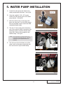
5. WATER PUMP INSTALLATION
A. Locate the water pump and attach to the
water pump bracket as shown. See fig 5A.
PUMP OUTLET
B. Using the supplied ¼-20 x .50” screws,
secure the water pump mount to the water
pump bracket. See fig 5B.
C. Mount the water pump to the driver side
frame rail using one (1) of the OEM screws
that was originally used to mount the OEM
windshield washer bottle.
PUMP INLET
D. Trim the ¾” hose coming from the bottom
port of the reservoir (that is mounted on the
passenger side) to connect with the water
pump inlet. Secure with a supplied nylon
ratchet clamp. See fig 5C.
Fig 5A
NOTE: Ensure that there are no pinched sections in the
hose attached to the inlet of the pump. Pump inlet
restrictions may cause significant reduction in
pump flow.
E. Trim the hose from the bottom port of the
water cooler to the water pump outlet and
then secure with a nylon ratchet clamp.
TRIM HOSES TO
LENGTH
SECURE WITH
FACTORY
HARDWARE
Fig 5B
SECURE WITH
CLAMPS
Fig 5C
39
P/N: 4LGE020-010 v3.1, 2012-03-12
© 2012 Lysholm
All Rights Reserved, Intl. Copr. Secured
F. Locate the 12-gage ground strap with two (2)
eyelets attached and cut one (1) end off.
Then connect a female spade connector as
shown. See fig 5D.
G. Replace the 16-gage ground wire from the
#86 pin position of the supplied relay assembly with the modified 12-gage supplied wire.
H. Locate the 10-gage fuse holder assembly
and cut the wire in the middle as shown.
Attach a ring terminal to one end and a
female spade connector on the opposite end.
See fig 5E.
I.
Fig 5D
Replace the 12-gage short red wire from the
#30 pin position of the supplied relay assembly with the modified 10-gage fuse assembly.
See fig 5F.
J. Install 20 amp fuse in fuse holder.
Fig 5E
Fig 5F
P/N: 4LGE020-010 v3.1, 2012-03-12
© 2012 Lysholm
All Rights Reserved, Intl. Copr. Secured
40
K. Position relay on the passenger side upper
radiator core support, adjacent to the coolant
fill tube. Mark the position and drill a hole
using an 11/64” drill bit. See fig 5G.
L. Using #12 sheet metal screws, attach the
relay ground and mount the relay. See fig
5H.
DRILL 11/64"
NOTE: Use a multimeter to verify a positive ground connection. If necessary remove the paint in the localized area of the ground connection.
Fig 5G
M. Route and trim the yellow relay wire to the
#20 fuse (Engine power) on the power distribution block. Using a fuse tap, connect the
wire to the fuse as shown. See fig 5I, 5J.
Fig 5H
Fig 5I
41
P/N: 4LGE020-010 v3.1, 2012-03-12
© 2012 Lysholm
All Rights Reserved, Intl. Copr. Secured
N. Using the OEM 13mm headed nut from the
power distribution block, secure the fused
wire. See fig 5J.
O. Run the water pump power wire (long red 16
gage) down the side of the radiator, under the
radiator core support to the water pump on
the driver side. Secure with tie wraps and
split loom. See fig 5K.
Fig 5J
Fig 5K
P/N: 4LGE020-010 v3.1, 2012-03-12
© 2012 Lysholm
All Rights Reserved, Intl. Copr. Secured
42
P. Use a butt connector to connect the power
wire to the supplied water pump connector.
Attach the other lead from the water pump
connector to a suitable ground (OEM horn
mounting screw) as pictured.
Q. Connect the connector to the water pump.
See fig 5M.
Fig 5L
Fig 5M
43
P/N: 4LGE020-010 v3.1, 2012-03-12
© 2012 Lysholm
All Rights Reserved, Intl. Copr. Secured
P/N: 4LGE020-010 v3.1, 2012-03-12
© 2012 Lysholm
All Rights Reserved, Intl. Copr. Secured
44
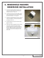
6. Windshield Washer
Reservoir INSTALLATION
A. Locate the supplied washer fluid tank and
ensure that the straight 5/8” barb fitting is
installed as shown in Fig. 6A.
B. Install the previously-removed OEM washer
pump and grommet into the similar location
on the new reservoir. See fig. 6B.
C. Install the supplied bracket onto the reservoir
using the supplied ¼-20 bolts and washers
as shown in Fig. 6A.
D. Install the plain cap onto the reservoir and
tighten securely.
Fig 6A
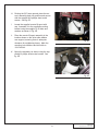
E. Place the reservoir assembly onto the driver
side frame rail with the bracket seating
squarely against the underside as shown in
Fig. 6D. Mark the position of the three (3)
mounting holes onto the underside of the
frame rail.
Fig 6B
45
P/N: 4LGE020-010 v3.1, 2012-03-12
© 2012 Lysholm
All Rights Reserved, Intl. Copr. Secured
F. Set the reservoir assembly aside and drill in
the three marked locations with an 11/64” –
3/16” drill bit. See fig. 6C.
G. Attach the supplied 5/8” hose to the barb on
top of the reservoir and secure with a supplied hose clamp.
DRILL 11/64"
Fig 6C
P/N: 4LGE020-010 v3.1, 2012-03-12
© 2012 Lysholm
All Rights Reserved, Intl. Copr. Secured
46
H. Routing the 5/8” hose upward, place the reservoir assembly back into position and secure
with the supplied #12 phillips sheet metal
screws. See fig. 6D.
I.
Locate the supplied remote fill spout with
cap. Assemble it to the supplied mounting
bracket using the supplied ¼-20 bolts and
washers as shown in Fig. 6E.
J. Place the remote fill spout assembly in the
location shown on the driver side radiator
core support, ensuring there is adequate
clearance for neighboring hoses. Mark the
mounting hole locations and drill with an
11/64” drill bit.
Fig 6D
K. Mount the assembly as shown using the supplied #12 phillips sheet metal screws. See
fig. 6E.
Fig 6E
47
P/N: 4LGE020-010 v3.1, 2012-03-12
© 2012 Lysholm
All Rights Reserved, Intl. Copr. Secured
L. Trim the 5/8” hose as necessary and connect
it to the bottom of the remote fill spout, securing it with the included clamps. See fig. 6F.
M. Reconnect the OEM electrical connector to
the washer pump.
N. Reconnect the washer fluid feed hose to the
washer pump.
Fig 6F
P/N: 4LGE020-010 v3.1, 2012-03-12
© 2012 Lysholm
All Rights Reserved, Intl. Copr. Secured
48
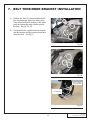
7. Belt tensioner BRACKET INSTALLATIOn
A. Remove the three (3) 10mm headed screws
from the passenger side of the water pump.
Clean all mounting bolt surfaces of the water
pump and passenger side cylinder head at
this time. See fig. 7A, 7B.
B. Pre-assemble the supplied tensioner bracket
and idler bracket using the spacers and hardware as shown. See fig 7C.
Fig 7A
Fig 7B
M10 X 1.5 X 50MM
W/ .75" SPACERS
M8 X 1.25 X 120MM
W/ 1.36" SPACERS
Fig 7C
49
P/N: 4LGE020-010 v3.1, 2012-03-12
© 2012 Lysholm
All Rights Reserved, Intl. Copr. Secured
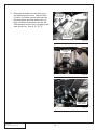
C. Mount the assembly onto the water pump
and OEM tensioner mount. Start the three
(3) M8x1.25x120mm screws that insert into
the water pump, and then start the two (2)
M10x1.5x50mm screws that insert into the
OEM tensioner mount. Don’t not tighten hardware at this time. See fig 7D, 7E, 7F.
M10 X 1.5 X 50MM
W/ .75" SPACERS
ATTACH HERE
M8 X 1.25 X 120MM
W/ 1.36" SPACERS
ATTACH HERE
Fig 7D
OEM TENSIONER
MOUNTS
Fig 7E
LOOSELY START
THESE SCREWS
Fig 7F
P/N: 4LGE020-010 v3.1, 2012-03-12
© 2012 Lysholm
All Rights Reserved, Intl. Copr. Secured
50
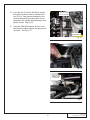
D. Insert the two (2) M10x1.50x120mm screws
through the tensioner plate to sandwich the
two (2) 3.22” long spacers between the tensioner plate and the grounding plate on the
passenger side cylinder head as shown, then
tighten screws. See fig 7G.
M10 X 1.5 X 120MM
W/ 3.22" SPACERS
E. Using the OEM M10 fastener and nut, reattach harness support clamps and ground wire
as shown. See fig 7H, 7I.
GROUNDING PLATE
Fig 7G
Fig 7H
ATTACH GROUND
TERMINAL W/ NUT
ON BACKSIDE
Fig 7I
51
P/N: 4LGE020-010 v3.1, 2012-03-12
© 2012 Lysholm
All Rights Reserved, Intl. Copr. Secured
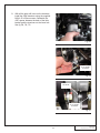
F. Mount OEM EVAP solenoid and bracket
using the supplied M8x1.25 x 8mm button
head with supplied washer to the ground
plate, as shown. See fig 7K.
M8X1.25X8MM
W/ WASHER
Fig 7J: EVAP Solenoid and bracket shown
mounted to ground plate.
Fig 7K
GROUND WIRE
Fig 7L
P/N: 4LGE020-010 v3.1, 2012-03-12
© 2012 Lysholm
All Rights Reserved, Intl. Copr. Secured
52
G. With all the bolts still loose on the brackets,
install the OEM tensioner using the supplied
M10x1.50 x 50mm screws. Sandwich the
.085” spacer between the back of the idler
bracket and the tensioner on the lower bolt.
See fig 7M, 7N, 7O.
Fig 7M
M10X1.5X50MM
W/ WASHER
Fig 7N
.085 SPACER
M10X1.5X50MM
W/ WASHER
Fig 7O
53
P/N: 4LGE020-010 v3.1, 2012-03-12
© 2012 Lysholm
All Rights Reserved, Intl. Copr. Secured
H. Assemble a supplied idler pulley as shown:
Insert M10x1.50x90mm screw with washer
through the idler dust shield, through the supplied idler, and then through the pilot spacer.
See fig 7P.
I.
.75" SPACER
Install the supplied .75” thick spacer between
the two mounting brackets in line with the top
most hole. Insert the previously assembled
idler and M10 screw through the brackets
and spacer and then tighten into the installed
PEM nut. See fig 7Q.
Fig 7P
J. Tighten all the screws mounted on the idler
bracket. See fig 7R.
.75" SPACER
Fig 7Q
Fig 7R
P/N: 4LGE020-010 v3.1, 2012-03-12
© 2012 Lysholm
All Rights Reserved, Intl. Copr. Secured
54
K. Assemble the other supplied idler pulley as
shown: Insert M10x1.50x50mm screw with
washer through the idler dust shield, through
the supplied idler, and then through the pilot
spacer. Insert idler and M10 screw thru hole
next to thermostat housing on idler bracket,
and then tighten. See fig 7S, 7T.
Fig 7S
Fig 7T
55
P/N: 4LGE020-010 v3.1, 2012-03-12
© 2012 Lysholm
All Rights Reserved, Intl. Copr. Secured
P/N: 4LGE020-010 v3.1, 2012-03-12
© 2012 Lysholm
All Rights Reserved, Intl. Copr. Secured
56
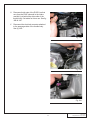
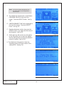
8. SUPERCHARGER INSTALLATIOn
A. Prior to installing the supercharger onto the
engine, be sure to move all electrical and
hoses clear of the cylinder head surfaces for
the supercharger to sit in.
ETC CONNECTOR
B. Attach the supplied ETC (Electronic Throttle
Control) extension and MAF/IAT harness to
the OEM harness conectors. Route the IAT
connector to the rear of the engine to be connected at a later point. See fig 8A, 8B, 8C.
Fig 8A
MAF CONNECTOR
Fig 8B
IAT CONNECTOR
Fig 8C
57
P/N: 4LGE020-010 v3.1, 2012-03-12
© 2012 Lysholm
All Rights Reserved, Intl. Copr. Secured
C. With an assistant, carefully lower the supercharger assembly on to the engine as shown.
NOTE: Remove tape from intake ports if previously used
to seal cylinder heads from debris.
D. Connect the IAT sensor harness as the
supercharger is lowered into place.
E. Ensure the vacuum lines are not pinched
between the cowl and the supercharger inlet.
Fig 8D
[OPTIONAL] BOOST
REFERENCE PORT
W/ FITTING INSTALLED
TO PASSENGER SIDE
TO DRIVER SIDE
Fig 8E
Fig 8F
P/N: 4LGE020-010 v3.1, 2012-03-12
© 2012 Lysholm
All Rights Reserved, Intl. Copr. Secured
58
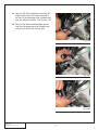
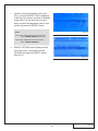
F. The supercharger should come to rest on the
pre-installed alignment guides which will prevent the supercharger from moving forward or
backward. Once it is seated in this position,
insert the remaining of the ten (10) M6x1.0 x
75mm long screws (five (5) per side) and
start each of them through the manifold.
Once each screw has been started by hand,
torque all ten (10) M6 screws to 95-100 in/lbs
evenly in a criss cross pattern starting from
the center and going outward. See fig 8F,
8G, 8H.
Fig 8G
G. Slide the OEM injector harness below the
injector connectors, as close to the manifold
as possible. Be sure to route the electrical
injector connectors under and out around the
harness to ensure that the connections have
adequate slack. See fig 8I.
Fig 8H
TUCK WIRING
HARNESS BELOW
INJECTOR
TERMINALS
Fig 8I
59
P/N: 4LGE020-010 v3.1, 2012-03-12
© 2012 Lysholm
All Rights Reserved, Intl. Copr. Secured
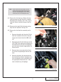
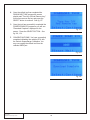
H. Connect all eight (8) fuel injector connectors.
NOTE: You may need to rotate the injector under the fuel
rail to slide the connector up and onto the fuel
injector connector to ensure a positive connection.
I.
Locate the supplied fuel feed line and connect to the hard fuel supply line on the frame
rail. Retain with OEM retaining clip. See fig
8K.
J. Connect the other end of the fuel feed line to
the back of the passenger side fuel rail.
Ensure that the fuel feed line is securely
tightened. See fig 8L.
Fig 8J
Fig 8K
Fig 8L
P/N: 4LGE020-010 v3.1, 2012-03-12
© 2012 Lysholm
All Rights Reserved, Intl. Copr. Secured
60
K. Modify the EVAP line that runs from the passenger side strut tower to the inlet side (black
side) of the EVAP solenoid as follows:
1. Remove the 45º quick disconnect fitting
from the factory evap line by carefully
cutting the hose along the fitting using a
utility knife. See fig 8N.
2. Using a 41.5" length of supplied 5/16"
emissions hose, attach the supplied 90º
quick disconnect fitting to one end and
secure using a supplied 14.5 stepless
clamp.
Fig 8M
3. On the opposite end of the 5/16" hose
attach the previously removed 45º quick
disconnect fitting to the hose and sercure using a supplied 14.5 stepless
clamp.
4. Connect the EVAP line to the line on the
frame rail, adjacent to the fuel feed line.
5. Route the line toward the rear of the car
around the coolant lines located at the
fire wall and back up to the front of the
vehicle along the fuel rail. Secure the
line as necessary with the supplied tie
wraps.
Fig 8N
L. Connect the 45º quick disconnect to the inlet
side (black side) of the EVAP solenoid.
Fig 8O
61
P/N: 4LGE020-010 v3.1, 2012-03-12
© 2012 Lysholm
All Rights Reserved, Intl. Copr. Secured
M. Connect the MAP sensor connector to the
MAP sensor at the front of the lower manifold. See fig 8P.
N. Connect the EVAP connector to the EVAP
solenoid. See fig 8Q.
O. Connect the ETC extension harness to the
throttle body. See fig 8R.
Fig 8P
Fig 8Q
Fig 8R
P/N: 4LGE020-010 v3.1, 2012-03-12
© 2012 Lysholm
All Rights Reserved, Intl. Copr. Secured
62
P. Locate the supplied serpentine belt and route
it as shown. See fig 8S, 8T.
Q. Cut a 13” long section of the supplied ¾”
heater hose, and then attach a ¾” union on
both sides. Secure with nylon ratchet clamps.
R. Attach one end of the previously assembled
hose to the water cooler outlet hose then
secure with a nylon ratchet clamp. See fig
8U.
Fig 8S
Fig 8T
Fig 8U
63
P/N: 4LGE020-010 v3.1, 2012-03-12
© 2012 Lysholm
All Rights Reserved, Intl. Copr. Secured
S. Trim to fit approximately 4.5” from the driver
side supercharger hose and attach the other
end of the previously assembled hose then
secure with a nylon ratchet clamp. See fig
8V, 8W.
T. Locate the surge tank and nickel plated fittings. Using thread sealant, attach the 90º fitting to the bottom of the surge tank then
attach the straight fitting to the side of the
tank. Ensure the bottom fitting is pointed in
the same direction as the straight fitting as
shown. See fig 8X.
Fig 8V
Fig 8W
Fig 8X
P/N: 4LGE020-010 v3.1, 2012-03-12
© 2012 Lysholm
All Rights Reserved, Intl. Copr. Secured
64
U. Pull away the cowl weather stripping from the
passenger side engine bay. See fig 8Y.
V. Remove the three (3) body clips, and then
pull the cowl trim panel up and forward away
from the windshield. See fig 8Z.
Fig 8Y
Fig 8Z
Fig 8AA
65
P/N: 4LGE020-010 v3.1, 2012-03-12
© 2012 Lysholm
All Rights Reserved, Intl. Copr. Secured
W. Temporarily position the surge tank bracket
onto the vehicle as shown and mark the hole
locations with a punch. See fig 8AB.
X. Use a 1/4” drill bit and drill out the holes on
the cowl.
Y. Mount the bracket on the underside of the
cowl using the two (2) supplied ¼-20x.375"
button head screws. See fig 8AC.
NOTE: Do not use washer under the button head screws.
Fig 8AB
Z. Mount the surge tank to the bracket using the
two (2) supplied ¼-20-.5" socket head cap
screws.
AA.Re-install the cowl trim panel and re-insert
the three body clips previously removed.
Reattach the cowl weather stripping.
AB.Trim the previously installed ¾” hose coming
up from under the power distribution block
and attach it to the bottom fitting on the surge
tank. Secure hose using a nylon ratchet
clamp. See fig 8AD.
Fig 8AC
Fig 8AD
P/N: 4LGE020-010 v3.1, 2012-03-12
© 2012 Lysholm
All Rights Reserved, Intl. Copr. Secured
66
AC.Attach a section of ¾” hose to the side fitting
on the surge tank and secure with a nylon
ratchet clamp.
AD.Insert a ¾ hose union on the other end of the
¾ hose to attach to the passenger side cooler hose coming out of the supercharger. Then
secure with a supplied nylon ratchet clamp.
See fig 8AE.
AE.Trim the passenger side CAC hose and connect to the surge tank hose with a nylon
ratchet clamp. See fig 8AG.
Fig 8AE
NOTE: Trim the hoses to length such that they travel in
smooth arcs free from kinks and away from hot
parts and sharp edges. Ensure adequate slack to
allow for moderate engine movement.
Fig 8AF
Fig 8AG
67
P/N: 4LGE020-010 v3.1, 2012-03-12
© 2012 Lysholm
All Rights Reserved, Intl. Copr. Secured
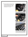
AF. Locate the supplied MAF housing, and install
the previously removed OEM MAF sensor
module into the housing using the supplied
M4x.7x8mm screws. Be sure to align the
flow direction arrow printed on the MAF sensor with the MAF housing, and that they point
toward the throttle body once installed.
Confirm that the supplied 1/4NPT X 3/8 barb
and 1/8NPT x 1/4 barb fittings are securely
installed in the MAF housing with proper
thread sealant. See fig 8AH.
AG.Using the supplied 4” hump hose coupler
with two (2) supplied #64 hose clamps,
attach the MAF housing to the throttle body
and orient as shown. See fig 8AI.
Fig 8AH
TO PASSENGER
VALVE COVER
BREATHER
NOTE: Failure to properly install this device can result in
engine damage or poor fuel economy.
AH.Locate a piece of 1/4" vacuum line and connect one end to the lower port on the bypass
actuator (marked with "P") and route it behind
the supercharger and thru to the MAF housing. Connect hose to the aluminum fitting
adjacent to the MAF sensor mount.
TO BYPASS
ACTUATOR "P" PORT
AI. Locate the previously installed MAF/IAT harness. Ensure the IAT connector end of the
harness is cleanly routed along the driverside
fuel rail and back toward the IAT sensor
located on the passenger-side rear of the
lower supercharger manifold just below the
bypass actuator. Confirm the connector is
attached to the IAT sensor.
Fig 8AI
AK. Connect the MAF connector of the MAF/IAT
harness to the MAF sensor installed in the
housing.
P/N: 4LGE020-010 v3.1, 2012-03-12
© 2012 Lysholm
All Rights Reserved, Intl. Copr. Secured
MAF CONNECTOR
68
AL. Locate the OEM EVAP line that was originally
attached to the EVAP solenoid and the intake
manifold behind the throttle body. Using a
utility knife, carefully cut the nylon tubing and
remove the 90º fitting. See fig 8AJ.
AM.Cut a 23” long section of the supplied 5/16”
fuel hose.
AN.Insert a supplied 14.5 stepless clamp on one
end of the hose and attach the 90º fitting.
Secure the fitting by compressing the clamp
ear. Install the connector on the gray side of
the EVAP solenoid as shown. See fig 8AK.
Fig 8AJ
Fig 8AK
Fig 8AL
69
P/N: 4LGE020-010 v3.1, 2012-03-12
© 2012 Lysholm
All Rights Reserved, Intl. Copr. Secured
AO.Route the free end as shown. Using another
14.5 stepless clamp, connect to the 5/16”
elbow fitting located on the back of the supercharger on the inlet duct. Secure the line by
compressing the clamps ears. See fig 8AM,
8AN, 8AO.
Fig 8AM
Fig 8AN
Fig 8AO
P/N: 4LGE020-010 v3.1, 2012-03-12
© 2012 Lysholm
All Rights Reserved, Intl. Copr. Secured
70
AP. Locate the OEM brake booster line and trim
the end without the check valve approx. 1.25"
from the bend as shown. See fig 8AP.
AQ.Insert the OEM check valve end back onto
the brake booster. Attach the modified end of
the hose to the brass barb fitting on the
supercharger inlet. Secure the hose using
the OEM hose clamp. See fig 8AP, 8AR.
AUTOMATIC ONLY: Reconnect the electrical connector to
the brake booster check valve.
Fig 8AP
Fig 8AQ
Fig 8AR
71
P/N: 4LGE020-010 v3.1, 2012-03-12
© 2012 Lysholm
All Rights Reserved, Intl. Copr. Secured
AR.Cut a length of supplied 3/8” hose and attach
one end to the crankcase breather port on
the front of the passenger side valve cover.
Route across and connect the other end to
the 3/8 barb fitting installed on the MAF housing. See fig 8AS, 8AT.
Fig 8AS
Fig 8AT
P/N: 4LGE020-010 v3.1, 2012-03-12
© 2012 Lysholm
All Rights Reserved, Intl. Copr. Secured
72
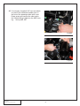
AS.Locate a length of supplied 3/8” hose.
1. Manual Transmisson:
Attach one end of the hose to the crankcase port on the lifter valley plate.
Route the hose alongside the passenger
side fuel rail around the back of the
supercharger.
2. Automatic Transmission:
Attach one end of the hose to the rear
vent port on the driverside valve cover
AT. Connect the other end to the 3/8” elbow fitting on the inlet duct (adjacent to the brake
booster fitting). See fig 8AV.
Fig 8AU
Fig 8AV
73
P/N: 4LGE020-010 v3.1, 2012-03-12
© 2012 Lysholm
All Rights Reserved, Intl. Copr. Secured
P/N: 4LGE020-010 v3.1, 2012-03-12
© 2012 Lysholm
All Rights Reserved, Intl. Copr. Secured
74
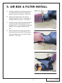
9. AIR BOX & FILTER INSTALL
A. Locate the supplied air box and conical air filter. Attach the filter using the included hose
clamp to the air box as shown. See fig 9A.
B. Attach the pedestal mount to the air box
using the supplied 1/4-20 x .5" hardware. Do
not tighten screw at this time. See fig 9B.
C. Locate the air box bracket support and attach
to the side of the air box using the two (2)
supplied 1/4-20 x .5" socket head screws and
washers. Do not tighten hardware at this
time.
Fig 9A
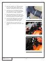
D. Remove the rubber mounting gromets and
metal shield from lower half of the factory air
box and reinstall them in the air box bracket
as shown. See fig 9C.
Fig 9B
Fig 9C
75
P/N: 4LGE020-010 v3.1, 2012-03-12
© 2012 Lysholm
All Rights Reserved, Intl. Copr. Secured
E. Attach the supplied 5” to 4” reducing coupler
to the air box with supplied clamps. Do not
tighten the included hose clamps at this time.
F. Lower the air box in to position by inserting
the air filter down in front of the splash guard
in the OEM air box location. See fig 9E.
G. Align the pedestal mount to the bottom support grommet on the frame rail, while inserting
the reducing coupler in to the MAF housing.
H. Ensure that the OEM rubber mounts on the
air box bracket are aligned with the OEM
mount studs located on the inner fender.
I.
Fig 9D
Using the OEM nuts, secure the air box
bracket to the inner fender mount studs. See
fig 9F.
Fig 9E
Fig 9F
P/N: 4LGE020-010 v3.1, 2012-03-12
© 2012 Lysholm
All Rights Reserved, Intl. Copr. Secured
76
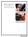
J. Tighten the two (2) 1/4-20 screws securing
the air box to the air box bracket, as well as
the 1/4-20 screw securing the pedestal mount
to the air box. See fig 9G, 9H.
K. Tighten the hose clamps attaching the reducing coupler to the air box and the MAF housing.
Fig 9G
Fig 9H
77
P/N: 4LGE020-010 v3.1, 2012-03-12
© 2012 Lysholm
All Rights Reserved, Intl. Copr. Secured
P/N: 4LGE020-010 v3.1, 2012-03-12
© 2012 Lysholm
All Rights Reserved, Intl. Copr. Secured
78
10. Final COMPONENT INSTALLATION
A. Reinstall the Front Bumper Cover (FBC) in
reverse order from removal making sure to
reinstall:
1. Two (2) 10mm-headed screws through
the bottom of the FBC.
2. The FBC electrical connector located
between the passenger side driving light
and headlight. Access the connector via
the wheel well.
3. Four (4) 10mm-headed screws and one
(1) 7mm-headed screw attaching the
FBC to the leading edge of the fender on
each side (8 and 2 total).
Fig 10A
4. Three (3) T20 Torx screws securing each
splash guard to the FBC (6 total). These
screws are located in the wheel wells
just forward of the front wheels along the
outer edge.
5. Two (2) plastic pins securing each
splash guard to the inner fender structure (4 total). One is adjacent to the
strut and the other is directly above the
wheel.
Fig 10B
6. Two (2) 10mm-headed screws and six
(6) plastic pins along the top edge of the
FBC.
B. Slowly refill the engine coolant through the
spout located at the top of the radiator, allowing any air to escape as the radiator fills. Fill
the engine coolant reservoir about 2/3 full.
Squeezing the upper radiator hose and the
air bleed hose, while you fill the radiator, will
aid with purging out the air from the system.
C. Using the washer fluid previously drained, fill
the washer fluid via the new remote fill spout.
Fill only so that the lower tank is filled.
Fig 10C
79
P/N: 4LGE020-010 v3.1, 2012-03-12
© 2012 Lysholm
All Rights Reserved, Intl. Copr. Secured
D. Fill the charge cooler system with a 75/25
water/antifreeze mixture through the top
opening on the surge tank. Fill slowly letting
air to purge out as the system is filled.
Reconnect the negative battery cable and
turn the key to the ON position (DO NOT
ATTEMPT TO START THE ENGINE). Make
sure that the water pump is operating and
that coolant is flowing through the surge tank.
Add coolant as needed. Check all fittings for
leaks. If the coolant is not flowing, remove
the charge cooler supply hose and lower until
coolant flows out of the hose. If necessary,
provide light suction to the hose to help prime
the pump. Verify coolant flow. Do not let the
pump run for more than 30 seconds without
coolant flow. Continue to check and fill the
system until the level stabilizes.
P/N: 4LGE020-010 v3.1, 2012-03-12
© 2012 Lysholm
All Rights Reserved, Intl. Copr. Secured
Fig 10E
80
E. Install supplied passenger coil cover as follows.
M6X1.0X25MM
M6X1.0X30MM
1. Remove the two (2) lower mounting
screws securing the #2 and #6 cylinder
coil packs to the coil mounting bracket on
the passenger side valve cover.
2. Install the two (2) supplied male/female
M6 standoffs in the lower mounting holes
of the #2 and #6 cylinder coil packs. See
fig 10F.
M6 STANDOFFS
3. Remove the four (4) upper mounting
screws securing the #2, #4, #6, and #8
cylinder coil packs to the coil mounting
bracket on the passenger side valve
cover. See fig 10F.
Fig 10F
4. Install the two (2) supplied M6x1.0x25mm
button head screws into the upper coil
pack mounting holes for cylinders #4 and
#8. See fig 10F.
5. Locate two (2) M6x1.0x30mm, two (2)
small diameter M6 washers, two (2) .175
spacers, two (2) spacer retaining washers, and aluminum coil cover.
M6X1.0X30MM, .175" SPACER AND
INTERNAL TOOTH LOCK WASHER
6. Install the M6x1.0x30mm screws with
small diameter M6 washers through the
two upper holes of the supplied coil cover
from the front, then from the back side,
install the .175 spacers followed by the
spacer retaining washers. See fig 10G.
Fig 10G
M6X1.0X30MM
7. Remove the oil fill cap, and install assembled coil cover as shown.
8. Thread the two (2) M6x1.0x30mm screws
into the upper holes in the OEM coil pack
mounting bracket and the two (2)
M6x1.0x16mm screws with small diameter M6 washers into the lower holes
threading into the previously installed
standoffs. See fig 10H.
M6X1.0X16MM
9. Reinstall oil cap, and check that all hoses
and wires are free from any sharp edges.
Fig 10H
81
P/N: 4LGE020-010 v3.1, 2012-03-12
© 2012 Lysholm
All Rights Reserved, Intl. Copr. Secured
P/N: 4LGE020-010 v3.1, 2012-03-12
© 2012 Lysholm
All Rights Reserved, Intl. Copr. Secured
82
11. Reflash Computer
IMPORTANT!
To ensure trouble-free programming of your vehicle’s computer:
• Make sure the vehicle's battery is sufficiently charged.
• Turn off all accessories and close doors to prevent unnecessary drain on the battery.
• Locate “exterior” fuse panel and remove Qty 1 INFO, Qty 1 RADIO and Qty 1RADIO AMP labeled fuses. (If applicable)
• Do not attempt to program your vehicle while a battery charger is connected
• Improper battery voltage will result in failure of the programming process.
• Do not disconnect the cable or turn off the ignition during programming.
NOTE: • All vehicles equipped with On-star that have
aftermarket stereos will experience problems
with the ability to re-program the vehicle’s ECM.
It is necessary to disconnect the aftermarket stereo from the factory wiring harness before continuing with the programming procedure.
ARROW KEYS
CANCEL
• Do not disturb the cable or turn the ignition off
during this time. If the programming is disrupted,
the computer will not start or run your vehicle!
SELECT
Fig. 11A
OBD2 CONNECTOR
A. Reconnect the battery if previously disconnected.
B. Locate the vehicle’s OBD2 connector
located under the dash on the driver
side of the vehicle. See fig 11B.
Fig 11B
C. Attach the OBD2 connector from the
Flash tool that is provided in the kit to
the vehicle’s OBD2 port. Make sure
this connector is seated all the way in
the vehicle’s OBD2 port. You don’t
want this connector to disconnect during programming or damage may
occur to the vehicle’s ECM. See fig
11C.
Fig 11C
83
P/N: 4LGE020-010 v3.1, 2012-03-12
© 2012 Lysholm
All Rights Reserved, Intl. Copr. Secured
NOTE: If you have any questions throughout this procedure, please contact our service department for
further assistance.
D. The reflash tool should power up and display
PROGRAM VEHICLE at the top of the
screen. Press the SELECT button. See fig
11D.
Fig 11D
E. PREPROGRAMED TUNE will be displayed at
the top of the screen. Press the SELECT
button. See fig 11E.
F. Read the disclaimer entirely, then press the
SELECT button if you agree with the terms of
the disclaimer. See fig 11F.
Fig 11E
G. At this point you will need to turn the ignition
to the ON position (do not start the vehicle).
Set the parking brake and press the SELECT
button to continue. See fig 11G.
H. The reflash tool will proceed to check the
Operating System (OS) part number of the
vehicles ECU. See fig 11H.
Fig 11F
Fig 11G
Fig 11H
P/N: 4LGE020-010 v3.1, 2012-03-12
© 2012 Lysholm
All Rights Reserved, Intl. Copr. Secured
84
I.
Once the tool has identified the OS of the
ECU, you will see SELECT AUTO displayed
at the top of the screen, and a list of available
tunes below. Use the arrow keys (up and
down) to select the appropriate tune for your
vehicle and press the SELECT button.
NOTE:
Fig 11I
If the vehicle is equipped with an automatic transmission,
select: "Lysholm Camaro A6" (see Fig 11I)
If the vehicle is equipped with a manual transmission,
select: "Lysholm Camaro M6"
J. ADJUST OPTIONS will be displayed at the
top of the screen. Arrow down to SKIP
OPTIONS and press the SELECT button.
See Fig 11J
Fig 11J
85
P/N: 4LGE020-010 v3.1, 2012-03-12
© 2012 Lysholm
All Rights Reserved, Intl. Copr. Secured
K. PROGRAM VEHICLE will be displayed at the
top of the screen. At this time make sure you
have turned off any additional accessories
that may cause unnecessary draw on the
vehicles battery (headlights, radio, etc.).Press
the SELECT button to proceed with BEGIN
PROGRAM. See Fig 11K
L. Automatic vehicles will require a second
selection. See Fig 11L.
Fig 11K
NOTE: Once the programming sequence has been started use care NOT to disturb the cable, or turn the
ignition or any accessories on or off during this
time. Throughout the programming sequence it is
normal for the Reflash tool to AUTOMATICALLY
cycle the vehicles power on and off. If the programming is disrupted, permanent damage to the
vehicles computer may result!
Fig 11L
Fig 11M
Fig 11N
P/N: 4LGE020-010 v3.1, 2012-03-12
© 2012 Lysholm
All Rights Reserved, Intl. Copr. Secured
86
M. The reflash tool will then automatically proceed through the following screens during the
programming process. See fig 11M thru 11S.
i. Unlock ECU
ii. Upload ECU
iii. Setup Device
iv. Make Adjustments
v. Calculate Checksums
vi. Unlock ECU
vii. Download tune
Fig 11O
Fig 11P
Fig 11Q
Fig 11R
Fig 11S
87
P/N: 4LGE020-010 v3.1, 2012-03-12
© 2012 Lysholm
All Rights Reserved, Intl. Copr. Secured
N. Once the reflash tool has completed the
DOWNLOAD TUNE process the screen
should read "Turn Key Off And Remove key."
At this time remove the key and press the
SELECT button to continue. See fig 11T.
O. Once the tool has successfully completed the
POWER DOWN ECU sequence you will see
"Download Complete" displayed on the
screen. Press the SELECT BUTTON. See
fig 11U, 11V.
Fig 11T
P. CONGRATULATIONS! You have successfuly
completed reflashing the vehicles ECU with
the Vortech Supercharger Calibration. You
may now unplug the reflash tool from the
vehicles OBD2 port.
Fig 11U
Fig 11V
P/N: 4LGE020-010 v3.1, 2012-03-12
© 2012 Lysholm
All Rights Reserved, Intl. Copr. Secured
88
12. FINAL CHECK
WARNING: Do not attempt to operate the vehicle until all components are installed and all
operations are completed including the final check.
A. If your vehicle has gone over 15,000 miles since its last spark plug
change, you will need to change the spark plugs now before test driving the vehicle.
B. Check all fitting, nuts, bolts and clamps for tightness. Pay particular
attention to oil and fuel lines around moving parts, sharp edges and
exhaust system parts. Make sure all wires and lines are properly
secured with clamps or tie-wraps.
C. Check all fluid levels, making sure that your fuel tank is filled with 91
octane or higher fuel before commencing test drive.
D. With the radiator cap still off, start the engine and allow to idle a few
minutes, then shut-off.
E. Re-check to be sure that no hoses, wires, etc. are near exhaust components, sharp edges or moving parts. Look also for any signs of fluid
leakage.
F. With the radiator cap removed, start the engine and allow to idle bringing the engine up to operating temperature. Watch the fluid level at
the radiator spout and fill as necessary.
G. Once the engine is up to normal operating temperature you can shut
the car off and replace the radiator cap. Check the overflow reservior
level and fill as necessary.
H. Check the CAC cooling system level and fill / purge as necessary. The
CAC surge tank should be 2/3 - 3/4 full after proper air purge. Do not
overfill.
I.
PLEASE TAKE SPECIAL NOTE: operating the vehicle without ALL the
subassemblies completely and properly installed may cause FAILURE
OF MAJOR COMPONENTS.
J. Test drive the vehicle.
K. Always listen carefully for engine detonation. Discontinue heavy throttle usage if detonation is heard.
L. Read the STREET SUPERCHARGER SYSTEM OWNER’S MANUAL
AND RETURN THE WARRANTY REGISTRATION FORM within thirty
(30) days of purchasing your supercharger system to qualify.
89
P/N: 4LGE020-010 v3.1, 2012-03-12
© 2012 Lysholm
All Rights Reserved, Intl. Copr. Secured
LYSHOLM SUPERCHARGER INTERNAL LUBRICATION
FLUID CHECK
This supercharger has been factory pre-filled with special
Lysholm synthetic lubricant. Oil does not need to be added
to a brand new unit; however a fluid level check should be
performed.
Prior to operating the supercharger on the vehicle and after
installation onto the vehicle:
Check the supercharger fluid level via the factory installed
dipstick located on the top of the supercharger case. Do not
operate the supercharger without it.
Fluid level checking procedure:
1. Ensure that the fiber sealing washer is located on the
dipstick base.
2. Thread the clean dipstick into the unit until it seats.
3. Once the dipstick has seated, remove the dipstick
from the unit. Fluid should register in the crosshatched area on the dipstick.
4. DO NOT OVERFILL!!! Drain excess fluid from the
unit if it is above the maximum level on the dipstick.
Check the supercharger fluid level using the dipstick (or sight
glass if equipped) at least every 5,000 miles.
The supercharger fluid must then be changed at least every
30,000 miles.
i. Drain the fluid, re-fill the unit only with 5.4 oz. (6.7oz for
3.3L) of Lysholm supplied lubricating fluid.
ii. Confirm proper oil level using the dipstick. DO NOT
OVERFILL!!
WARNING: P/N: 4LGE020-010 v3.1, 2012-03-12
© 2012 Lysholm
All Rights Reserved, Intl. Copr. Secured
Use of any other fluid other than the special Lysholm lubricant will
void the warranty and may cause component failure.
90
1650 Pacific Avenue, Channel Islands CA 93033-9901
Phone: 805 247-0226 • Fax: 805 247-0669 • www.lysholm.us
91
P/N: 4LGE020-010 v3.1, 2012-03-12
© 2012 Lysholm
All Rights Reserved, Intl. Copr. Secured