1
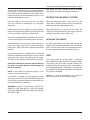
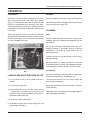
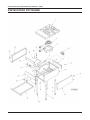
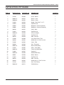
INSTALLATION, OPERATION, SERVICE &
PARTS MANUAL
FOR STOCK POT RANGE
MODELS VSP100, VSP200 & VSP300
MODEL VSP100
VULCAN-HART
FORM 30780 (3-92)
COMPANY,
P.O.
BOX
696,
LOUISVILLE,
KY
40201-0696,
TEL. (502) 7 7 8 - 2 7 9 1
STOCK POT INSTALLATION, OPERATION, SERVICE & PARTS
IMPORTANT FOR YOUR SAFETY
THIS MANUAL HAS BEEN PREPARED FOR PERSONNEL QUALIFIED TO INSTALL GAS
EQUIPMENT, WHO SHOULD PERFORM THE INITIAL FIELD START-UP AND ADJUSTMENTS
OF THE EQUIPMENT COVERED BY THIS MANUAL.
POST IN A PROMINENT LOCATION THE INSTRUCTIONS TO BE FOLLOWED IN THE
EVENT THE SMELL OF GAS IS DETECTED. THIS INFORMATION CAN BE OBTAINED
FROM THE LOCAL GAS SUPPLIER.
IMPORTANT
IN THE EVENT A GAS ODOR IS DETECTED, SHUT
DOWN UNITS AT MAIN SHUTOFF VALVE AND
CONTACT THE LOCAL GAS COMPANY OR GAS
SUPPLIER FOR SERVICE.
FOR YOUR SAFETY
DO NOT STORE OR USE GASOLINE OR OTHER
FLAMMABLE VAPORS OR LIQUIDS IN THE
VICINITY OF THIS OR ANY OTHER APPLIANCE.
WARNING
IMPROPER INSTALLATION, ADJUSTMENT,
ALTERATION OR MODIFICATION, SERVICE OR
MAINTENANCE CAN CAUSE PROPERTY DAMAGE,
INJURY OR DEATH. READ THE INSTALLATION,
OPERATING AND MAINTENANCE INSTRUCTIONS
THOROUGHLY BEFORE INSTALLING OR
SERVICING THIS EQUIPMENT.
IN THE EVENT OF A POWER FAILURE, DO NOT
ATTEMPT TO OPERATE THIS DEVICE.
–2–
STOCK POT INSTALLATION, OPERATION, SERVICE & PARTS
INSTALLATION, OPERATION, SERVICE & PARTS MANUAL
STOCK POT RANGES
MODELS VSP100, VSP200 & VSP300
INDEX
PLEASE KEEP THIS MANUAL FOR FUTURE REFERENCE
Your Vulcan Stock Pot Range is produced with quality
workmanship and material. Proper installation, usage
and maintenance of your range will result in many years
of satisfactory performance.
DESCRIPTION
The manufacturer suggests that you thoroughly read this
entire manual and carefully follow all of the instructions
provided.
PAGE
INDEX
3
INSTALLATION
4-6
UNCRATING
4
LOCATION
4
INSTALLATION CODES AND STANDARDS
4
GAS CONNECTIONS
4-5
TESTING THE GAS SUPPLY SYSTEM
5
LEVELING THE RANGE
5
VENT
5
ADJUSTMENTS
6
OPERATION
7
CONTROLS
7
LIGHTING AND SHUTTING DOWN PILOTS
7
CLEANING
7
MAINTENANCE
8
LUBRICATION
8
SERVICE
8
TROUBLESHOOTING
8
REPLACEMENT PARTS LIST
9-11
–3–
STOCK POT INSTALLATION, OPERATION, SERVICE & PARTS
INSTALLATION
NOTE: When installing this appliance, the bottom area
of the range should remain open to allow air circulation
for the gas burner. NEVER BLOCK THE BOTTOM
AREA OF THE RANGE.
Do not permit fans to blow directly at the range, and
whenever possible, avoid open windows next to the
range sides or back. Avoid wall type fans which create
air cross currents within the room.
UNCRATING
INSTALLATION CODES AND STANDARDS
This stock pot range was inspected before leaving
the factory. The transportation company assumes full
responsibility for safe delivery upon acceptance of the
shipment. Immediately after uncrating, check for possible shipping damage. If the range is found to be
damaged after unpacking, save the packaging material
and contact the carrier within 15 days of delivery.
For proper installation procedures, refer to:
United States
1. State and local codes.
2. National Fuel Gas Code, ANSI-Z223 1 (latest edition). Copies may be obtained from The American
Gas Association, 1515 Wilson Blvd Arlington, VA
22209.
Before installing, verify that the type of gas supply (natural or propane) agrees with the specifications on the
rating plate located on the back of the range. If the supply
and equipment requirements do not agree, do not
proceed with the installation Contact your dealer or
Vulcan-Hart Company immediately.
Canada
1. Local codes.
2. CAN/CGA-B149.1 Installation for Natural Gas
Burning Appliances and Equipment (latest edition).
LOCATION
3. CAN/CGA B149.2 Installation for Propane Burning
Appliances and Equipment (latest edition). Copies
may be obtained from The Canadian Gas Association, 55 Scarsdale Road, Don Mills, Ontario, Canada
MSB 2R3.
This range is design certified for installation in noncombustible locations only.
The equipment area must be kept free and clear of
combustible substances.
The range, when installed, must have a minimum
clearance of 6" at the sides and 6" at the rear from
combustible and non-combustible construction.
GAS CONNECTIONS
CAUTION: All gas supply connections and any pipe
joint compound used must be resistant to the action
of propane gases.
The installation location must allow adequate clearances for servicing and proper operation. A minimum
front clearance of 24" is required.
The Model VSP100 Range has one burner, Model
VSP200 has two burners, and Model VSP300 has three
burners. On all models, each burner has an individual
gas connection.
The range must be installed so that the flow of combustion and ventilation air will not be obstructed. Adequate
clearance for air openings into the combustion chamber
must be provided. Make sure there is an adequate
supply of air in the room to allow for combustion of the
gas at the burners.
–4–
STOCK POT INSTALLATION, OPERATION, SERVICE & PARTS
After piping has been checked for leaks, all piping
receiving gas should be fully purged to remove air.
The gas inlet is located at the rear and lower left side
of the range. To ensure maximum operating efficiency,
the range must be connected with a gas supply line as
large or larger ID (net inside diameter) than the 3⁄4" gas
pipe inlet provided on the range.
TESTING THE GAS SUPPLY SYSTEM
Pipe gas supply to the range. Make sure the pipes
are clean and free of obstructions, dirt, and piping
compound.
When test pressures exceed 1⁄2 psig (3.45 k Pa), the
range and its individual shutoff valve must be disconnected from the gas supply piping system.
Codes require that a gas shutoff valve be installed in
the gas line ahead of the range. Be sure the gas shutoff
valve is accessible in the final installed location.
When test pressure are 1⁄2 psig (3.45 k Pa) or less, the
range must be isolated from the gas supply system by
closing its individual manual shutoff valve.
All ranges are equipped with fixed orifices for use with
natural or propane gas and no adjustment is necessary.
LEVELING THE RANGE
Standard orifices are set at 5" W.C. (Water Column) for
natural gas supply, and 10" W.C. (Water Column) for
propane gas supply. No further adjustment should be
required.
Once gas connections have been made, position the
range in its final installation location. Place a carpenters
level on the top grate and turn the adjustable feet to
level the range from side-to-side and front-to-back.
A gas pressure regulator is supplied with the range and
must be installed on the manifold pipe at the rear of the
range when the range is connected to the gas supply.
The arrow on the regulator shows direction of gas flow.
CAUTION: Installing the pressure regulator with the
gas flow in the wrong direction could damage the
pressure regulator.
NOTE: If the proper gas pressure regulator is not
installed, it will void the warranty.
A leak limiter is supplied with every regulator to allow
excess gas pressure to escape. Do not obstruct the leak
limiter on the gas pressure regulator as obstruction may
cause the regulator to malfunction.
WARNING: PRIOR TO LIGHTING, CHECK ALL
JOINTS IN THE GAS SUPPLY LINE FOR LEAKS.
USE SOAP AND WATER SOLUTION. DO NOT USE
AN OPEN FLAME.
–5–
VENT
The range should be located under a ventilation
hood. Construction and installation of ventilating hoods
must comply with local codes and with National Fire
Protection Association Standard #96, “Vapor Removal
from Cooking Equipment” (latest edition), available from
the National Fire Protection Association, Battery March
Park, Quincy, MA 02269.
Adequate air should be provided in the kitchen to
replace air taken out by the ventilating system.
STOCK POT INSTALLATION, OPERATION, SERVICE & PARTS
ADJUSTMENTS
Air Supply
Pilot Adjustment
Air supply is controlled by an air shutter on the front of
each burner. Increase the air shutter openings until the
flame on the burner begins to “lift.” Then close the air
shutter slightly and lock it in place. A yellow streaming
flame is an indication of insufficient air and can result in
carbon accumulation in the flame chamber. To correct
this condition, increase the air shutter opening. Excessive air will cause flames to lift off a burner when cold or
may cause flash-back during normal cycling of the range,
particularly when propane gas is used.
Turn burner valves on to remove air from the line. Turn
burner valves off when gas begins to flow. Wait 5 minutes
and light pilot. Adjust pilot to 1⁄4" flame by rotating pilot
valve adjusting screw (Fig. 1) clockwise to decrease and
counterclockwise to increase flame.
Burner Adjustment
The efficiency of the range depends on the proper
balance between the supply of air and volume of gas so
that complete combustion is achieved. Whenever this
balance is disturbed, poor operating characteristics and
excessive gas consumption occur. Contact a qualified
servicer to make this adjustment.
Fig. 1
–6–
STOCK POT INSTALLATION, OPERATION, SERVICE & PARTS
OPERATION
CONTROLS
Shutdown
The burner is in two sections, controlled by two heavy
duty infinite control valves. The center “Star” section
(Fig. 2) is one separate burner with an input of 55,000
BTU/hr. It is controlled by the right burner valve knob.
The outer circle of the burner (Fig. 2) is the other separate
55,000 BTU/hr input burner, controlled by the left burner
valve knob.
For daily shutdown, turn burner valves to OFF position.
These two separate burners provide heat flexibility.
With one burner off and the second burner set low, or up
to both burners full on, you can move from low simmer
on up to 110,000 BTU/hr input.
Daily
For seasonal shutdown, extinguish pilot and turn burner
valves and main gas supply OFF.
CLEANING
Stainless steel should be cleaned with a damp cloth.
Stubborn soil may be removed with detergent. (Do not
use “Dawn”.)
Do not use scouring powder except with great care.
Scouring powder is extremely difficult to remove
completely. It can build up accumulations that will
damage the finish.
Painted surfaces may be cleaned with a cloth using a
detergent solution.
All places where oil, grease or food can accumulate
must be kept clean at all times. Use a detergent solution,
rinse thoroughly, and wipe dry with a soft clean cloth.
As Required
Fig. 2
LIGHTING AND SHUTTING DOWN PILOTS
When cool, periodically remove grates and clean area
around and under burners, including drip tray.
1. Turn all burner valves to OFF position and wait 5
minutes.
The capacity of the drip tray is 33⁄4 quarts. Empty drip
tray and clean periodically.
2. Turn main gas supply ON.
When cool, thoroughly clean burners, ports and burner
throats (venturi).
3. Light standing pilot with a lit taper. Adjust pilot to
1
⁄4" high flame, if necessary, by turning pilot valve
adjusting screw counterclockwise to increase or
clockwise to decrease flame.
4. Turn burner valve to ON position.
5. If pilot does not light, turn main gas supply OFF and
repeat Steps 1 through 4.
–7–
Keep pilots clean and adjusted at the proper height to
ensure complete combustion.
STOCK POT INSTALLATION, OPERATION, SERVICE & PARTS
MAINTENANCE
LUBRICATION
All valves and thermostats must be checked and
lubricated periodically. Contact your Vulcan-Hart
authorized servicer.
Contact personnel qualified to install and repair gas
equipment for all other maintenance.
SERVICE
SHUTOFF VALVE
PRESSURE REGULATOR
The gas shutoff valve is located to the rear of the range
and is used to shut the range down when gas components require servicing. This valve is also used to turn
off all gas to the range when the range is being shut down
for an extended period of time.
The pressure regulator is located at the rear of the
range downstream of the shutoff valve. Turn off the main
gas supply upstream of the shutoff valve and pressure
regulator before servicing the pressure regulator, then
remove the shutoff valve and pressure regulator.
Turn off the main gas supply upstream of the shutoff
valve before servicing the valve.
TROUBLESHOOTING
PROBLEM
PROBABLE CAUSES
Pilot outage
Pilot flame too low.
Restriction in pilot orifice.
Restriction in pilot valve.
Improper burner combustion
Improper ventilation.
Poor Ignition
Insufficient gas input.
Poor air-gas adjustment.
Restriction in pilot orifice.
Restriction in main burner ignition port.
Restriction in control valve.
Restriction in gas orifice.
–8–
STOCK POT INSTALLATION, OPERATION, SERVICE & PARTS
REPLACEMENT PARTS LIST
REPLACEMENT PARTS ORDERING
The following information must accompany a replacements parts order or it cannot be filled.
A.
B.
C.
D.
Model and style or serial number.
Type of gas (natural or propane).
Voltage and phase.
Appliance finish, permafinish, stainless steel, etc (if applicable to part to be replaced).
Use rating plate located on back of range to help you obtain the information listed above. This plate will provide all
the necessary information required by the service agency.
Parts may be ordered only from your authorized parts and service depot. For assistance in locating your nearest
authorized parts and service depot, contact:
Product Service Department
Vulcan-Hart Company
2006 Northwestern Pkwy.
Louisville, KY 40203
FAX# (502) 778-8510
ALL SERVICE PERSONNEL
WHEN SERVICING THIS EQUIPMENT, USE ONLY
CONTROLS ORIGINALLY SUPPLIED ON THIS EQUIPMENT BY
VULCAN-HART COMPANY.
DO NOT SUBSTITUTE.
SUBSTITUTION OF CONTROLS AS STATED ABOVE
WILL AUTOMATICALLY VOID THIS WARRANTY
AND THE CERTIFICATION ASSOCIATED WITH THIS EQUIPMENT.
–9–
STOCK POT INSTALLATION, OPERATION, SERVICE & PARTS
VSP100 STOCK POT RANGE
– 10 –
STOCK POT INSTALLATION, OPERATION, SERVICE & PARTS
VSP100 STOCK POT RANGE
ITEM NO.
NEW PART NO.
OLD PART NO.
DESCRIPTION
QUANTITY
1
715183
843750
Grate - Burner
1
2
760631-A
843751
Burner - Inner
1
3
760630-A
843752
Burner - Outer
1
4
719959
843753
Nipple - Black Pipe 3⁄4 x 171⁄2
1
5
719874
843754
Pop Rivet 1/8
2
6
720064
843755
Regulator - Pressure (Natural)
1
7
720065
843756
Regulator - Pressure (Propane)
1
8
760758
843757
Panel - Back
1
9
719874
843754
Pop Rivet 1/8
2
10
760603-A
843758
Chassis (Single)
1
11
719874
843754
Pop Rivet 1/8
4
12
760759
843759
Side - Plant-On
13
719280
843760
1
1
Leg - Black Pipe 1 ⁄4 Dia.
1
4
14
730228
843761
Screw 10-24 x ⁄2 Phil. Pan Hd.
4
15
719285
843762
Insert - Foot
4
16
730509
843763
Clip - Tinnerman
2
17
760627-A
843764
Drip Pan Weld Assy.
1
18
719255
843765
Knob - Valve (Red)
2
19
760624-A
843766
Front Panel Weld Assy.
1
20
719004
843767
Coupling 1⁄4
1
21
760620-A
843768
Manifold Sub Assy.
1
22
760851
843769
Baffle - Burner
1
23
719874
843754
Pop Rivet 1/8
2
24
760759
843759
Side - Plant-On
1
1
25
730228
843761
Screw 10-24 x ⁄2 Phil. Pan Hd.
2
26
715194
843770
Clip - Pilot Tubing
2
27
760619-A
843771
Pilot Sub Assy.
1
– 11 –
THIS
PAGE
INTENTIONALLY
LEFT
BLANK