1
-( I. It Ii
~
"
~
~
~
.
1ft
..,.
~
o
q
~LD""
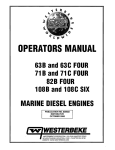
SERVICE MANUAL
FOR THE
82B FOUR MARINE DIESEL ENGINE
AND THE
25KW-60Hz BED /20KW-50Hz BED
MARINE DIESEL GENERATORS
SINGLE PHASE & THREE PHASE
PUBLICATION NO. 040485
EDITION ONE
NOVEMBER 1998
~r~ 'WESTERBEKE
~
WESTERBEKECORPORATION
MYLES STANDISH INDUSTRIAL PARK
150 JOHN HANCOCK ROAD, TAUNTON, MA 02780-7319
N~A Member NmioMl Marine Manufacture" Associatwn
•
CALIFORNIA
PROPOSITION 65 WARNING
Diesel engine exhaust and some
of its constituents are known to
the State of California to cause
cancer, birth defects, and other
reproductive harm.
A
WARNING
Exhaust gasses contain Carbon Monoxide, an odorless and
colorless gas. Carbon Monoxide is poisonous and can cause
unconsciousness and death. Symptoms of Carbon Monoxide
exposure can include:
- Throbbing in Temples
- Dizziness
-Nausea
- Muscular Twitching
-Headache
- Vomiting
- Weakness and Sleepiness -Inability to Think Coherently
IF YOU OR ANYONE ELSE EXPERIENCE ANY OF THESE SYMPTOMS,
GET OUT INTO THE FRESH AIR IMMEDIATELY. If symptoms persist,
seek medical attention. Shut down the unit and do not restart
until it has been inspected and repaired.
SAFETY INSTRUCTIONS
INTRODUCTION
PREVENT BURNS - FIRE
Read this safety manual carefully. Most accidents are
caused byfailure to follow fundamental rules and precautions. Know when dangerous conditions exist and take the
necessary precautions to protect yourself, your personne~
and your machinery.
The following safety instructions are in compliance with the
American Boat and Yacht Council (ABYC) standards.
•
PREVENT ELECTRIC SHOCK
•
A WARNING: Do not touch AC electrical connections
while engine is running, or when connected to shore
power. Lethal voltage is present at these connections!
•
•
•
•
•
•
•
Do not operate this machinery without electrical
enclosures and covers in place.
Shut off electrical power before accessing electrical
equipment.
Use insulated mats whenever working on electrical
equipment.
Make sure your clothing and skin are dry, not damp
(particularly shoes) when handling electrical equipment.
Remove wristwatch and all jewelry when working on
electrical equipment.
Do not connect utility shore power to vessel's AC
circuits, except through a ship-to-shore double throw
transfer switch. Damage to vessel's AC generator may
result if this procedure is not followed.
Electrical shock results from handling a charged capacitor. Discharge capacitor by shorting terminals together.
A WARNING: Fire can cause injury or death!
•
•
•
PREVENT BURNS - EXPLOSION
A WARNING: Explosions from fuel vapors can cause
injury or death!
•
•
PREVENT BURNS - HOT ENGINE
•
•
A WARNING: Do not touch hot engine parts or
exhaust system components. A running engine gets
very hot!
•
Always check the engine coolant level at the coolant
recovery tank.
A WARNING: Steam can cause injury or death!
•
In case of an engine overheat, allow the engine to cool
before touching the engine or checking the coolant.
Prevent flash fires. Do not smoke or permit flames or
sparks to occur near the carburetor, fuel line, filter, fuel
pump, or other potential sources of spilled fuel or fuel
vapors. Use a suitable container to catch all fuel when
removing the fuel line, carburetor, or fuel filters.
Do not operate with a Coast Guard Approved flame
arrester removed. Backfire can cause severe injury or
death.
Do not operate with the air cleaner/silencer removed.
Backfire can cause severe injury or death.
Do not smoke or permit flames or sparks to occur near
the fuel system. Keep the compartment and the
engine/generator clean and free of debris to minimize the
chances of fire. Wipe up all spilled fuel and engine oil.
Be aware - diesel fuel will bum.
•
•
•
•
Follow re-fueling safety instructions. Keep the vessel's
hatches closed when fueling. Open and ventilate cabin
after fueling. Check below for fumes/vapor before running the blower. Run the blower for four minutes before
starting your engine.
All fuel vapors are highly explosive. Use extreme care
when handling and storing fuels. Store fuel in a well-ventilated area away from spark-producing equipment and
out of the reach of children.
Do not fill the fuel tank(s) while the engine is running.
Shut off the fuel service valve at the engine when servicing
the fuel system. Take care in catching any fuel that might
spill. DO NOT allow any smoking, open flames, or other
sources of fire near the fuel system or engine when servicing. Ensure proper ventilation exists when servicing the
fuel system.
Do not alter or modify the fuel system.
Be sure all fuel supplies have a positive shutoff valve.
Be certain fuel line fittings are adequately tightened and
free of leaks.
Make sure a fire extinguisher is installed nearby and is
properly maintained. Be familiar with its proper use.
Extinguishers rated ABC by the NFPA are appropriate
for all applications encountered in this environment.
Engines & Generators
SAFETY INSTRUCTIONS
TOXIC EXHAUST GASES
ACCIDENTAL STARTING
A WARNING: Accidental starting can cause injury
A WARNING: carbon monoxide (CO) is a deadly gas!
or death!
•
Disconnect the battery cables before servicing the engine!
generator. Remove the negative lead first and reconnect
it last.
•
Make certain all personnel are clear of the engine before
starting.
•
Make certain all covers, guards, and hatches are reinstalled before starting the engine.
•
Ensure that the exhaust system is adequate to expel gases
discharged from the engine. Check the exhaust system
regularly for leaks and make sure the exhaust manifolds
are securely attached and no warping exists. Pay close
attention to the manifold, water injection elbow, and
exhaust pipe nipple.
•
Be sure the unit and its surroundings are well ventilated.
•
In addition to routine inspection of the exhaust system,
install a carbon monoxide detector. Consult your boat
builder or dealer for installation of approved detectors.
BATTERY EXPLOSION
•
A WARNING: Battery explosion can cause injury
For additional information refer to ABYC T-22 (educational information on Carbon Monoxide).
or death!
•
•
A WARNING: Carbon monoxide (CO) is an invisible
Do not smoke or allow an open flame near the battery
being serviced. Lead acid batteries emit hydrogen, a
highly explosive gas, which can be ignited by electrical
arcing or by lit tobacco products. Shut off all electrical
equipment in the vicinity to prevent electrical arcing during servicing.
odorless gas. Inhalation produces flu-like symptoms,
nausea or death!
Never connect the negative (-) battery cable to the positive (+) connection tenninal of the starter solenoid. Do
not test the battery condition by shorting the tenninals
together. Sparks could ignite battery gases or fuel vapors.
Ventilate any compartment containing batteries to prevent
accumulation of explosive gases. To avoid sparks, do not
disturb the battery charger connections while the battery
is being charged.
•
Avoid contacting the tenninals with tools, etc., to prevent
burns or sparks that could cause an explosion. Remove
wristwatch, rings, and any other jewelry before handling
the battery.
•
Always turn the battery charger off before disconnecting
the battery connections. Remove the negative lead first
and reconnect it last when disconnecting the battery.
•
Do not use copper tubing in diesel exhaust systems. Diesel
fumes can rapidly destroy copper tubing in exhaust systems. Exhaust sulfur causes rapid deterioration of copper
tubing resulting in exhaust/water leakage.
•
Do not install exhaust outlet where exhaust can be drawn
through portholes, vents, or air conditioners. If the engine
exhaust discharge outlet is near the waterline, water could
enter the exhaust discharge outlet and close or restrict the
flow of exhaust. Avoid overloading the craft.
•
Although diesel engine exhaust gases are not as toxic as
exhaust fumes from gasoline engines, carbon monoxide
gas is present in diesel exhaust fumes. Some of the symptoms or signs of carbon monoxide inhalation or poisoning
are:
Vomiting
Dizziness
Throbbing in temples
Muscular twitching
BATTERY ACID
Intense headache
A WARNING: Sulfuric acid in batteries can cause
Weakness and sleepiness
severe injury or death!
•
AVOID MOVING PARTS
When servicing the battery or checking the electrolyte
level, wear rubber gloves, a rubber apron, and eye protection. Batteries contain sulfuric acid which is destructive.
If it comes in contact with your skin, wash it off at once
with water. Acid may splash on the skin or into the eyes
inadvertently when removing electrolyte caps.
A WARNING: Rotating parts can cause injury
or death!
•
Do not service the engine while it is running. If a situation arises in which it is absolutely necessary to make
operating adjustments, use extreme care to avoid touching
moving parts and hot exhaust system components.
Engines & Generators
ii
SAFETY INSTRUCTIONS
•
•
•
•
ABYC, NFPA AND USCG PUBLICATIONS FOR
INSTALLING DIESEL ENGINES
Do not wear loose clothing or jewelry when servicing
equipment; tie back long hair and avoid wearing loose
jackets, shirts, sleeves, rings, necklaces or bracelets that
could be caught in moving parts.
Read the following ABYC, NFPA and USCG publications
for safety codes and standards. Follow their recommendations when installing your engine.
Make sure all attaching hardware is properly tightened.
Keep protective shields and guards in their respective
places at all times.
ABYC (American Boat and Yacht Council)
"Safety Standards for Small Craft"
Do not check fluid levels or the drive belt's tension while
the engine is operating.
Order from:
ABYC
15 East 26th Street
New York, NY 10010
NFPA (National Fire Protection Association)
"Fire Protection Standard for Motor Craft"
Order from:
Stay clear of the drive shaft and the transmission coupling
when the engine is running; hair and clothing can easily
be caught in these rotating parts.
HAZARDOUS NOISE
A WARNING: High noise levels can cause hearing
National Fire Protection Association
11 Tracy Drive
Avon Industrial Park
Avon, MA 02322
USCG (United States Coast Guard)
"USCG 33CFR183"
loss!
•
Never operate an engine without its muffler installed.
•
Do not run an engine with the air intake (silencer)
removed.
.
•
Do not run engines for long periods with their enclosures
open.
Order from:
U.S. Government Printing Office
Washington, D.C. 20404
A WARNING: 00 not work on machinery when you are
mentally or physically incapacitated by fatigue!
OPERATORS MANUAL
Many of the preceding safety tips and warnings are repeated
in your Operators Manual along with other cautions and
notes to highlight critical information. Read your manual
carefully, maintain your equipment, and follow all safety
procedures.
ENGINE INSTALLATIONS
Preparations to install an engine should begin with a thorough examination of the American Boat and Yacht Council's
(ABYC) standards. These standards are a combination of
sources including the USCG and the NFPA.
Sections of the ABYC standards of particular interest are:
H-2 Ventilation
P-l Exhaust systems
P-4 Inboard engines
E-9 DC Electrical systems
All installations must comply with the Federal Code of
Regulations (FCR).
Engines & Generators
iii
INSTALLATION
When installing WESTERBEKE engines and generators it is important that strict
attention be paid to the following information:
CODES AND REGULATIONS
Strict federal regulations, ABYC guidelines, and safety codes must be complied with
when installing engines and generators in a marine environment.
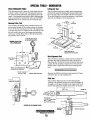
SIPHON-BREAK
For installations where the exhaust manifold/water injected exhaust elbow is close to
or will be below the vessel's waterline, provisions must be made to install a siphonbreak in the raw water supply hose to the exhaust elbow. This hose must be looped a
minimum of 20" above the vessel's waterline. Failure to use a siphon-break when
the exhaust manifold injection port is at or below the load waterline will result in
raw water damage to the engine and posswle flooding of the boat.
EXHAUST SYSTEM
The exhaust hose must be certified for marine use. The system must be designed to
prevent water from entering the exhaust under any sea conditions and at any angle
of the vessels hull.
A detailed 40 page Marine Installation Manual covering gasoline and
diesel, engines and generators, is available from your WESTERBEKE
dealer.
Engines & Generators
iv
TABLE OF CONTENTS
Introduction ................................................................2
Engine Troubleshooting (Chart) ................................. .3
Testing for Overhaul ...................................................7
Engine I Generator Disassembly ................................8
Engine Disassembly ....................................................9
Engine Inspection ..................................................... 14
Engine Assembly .......................................................24
Exhaust ManifoldlHeat Exchanger .......................... .31
Fuel Injection Pump .................................................32
Fuel Injection Pump!Fuellift pump .........................33
Fuel Injectors............................................................34
Fuel System Troubleshooting ...................................36
Glow Plugs ................................................................38
Engine Adjustments ..................................................39
Coolant Circulating Pump ........................................41
Lubricating Oil Pump ................................................42
Oil Pressure ..............................................................43
Starter Motor ...... '" ...................................................45
Tachometer ......... '" ...................................................49
Alternator Testing .....................................................50
Engine Wiring Diagram .............................................52
Engine Wiring Schematic .........................................53
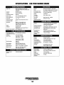
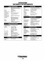
Engine Specifications ...............................................54
Engine Standards and Limits ....................................55
Engine Torque Specifications...................................57
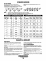
Standard Hardware Torques .....................................58
Generator Information ..............................................59
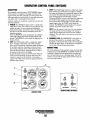
Generator Control Panel SWitches ...........................60
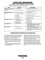
Control Panel Troubleshooting .................................61
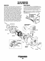
BE Generator ............................................................62
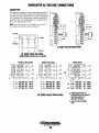
Generator AC Voltage Connections .........................63
Voltage Regulator Adjustments ...............................65
Internal Wiring Schematics......................................66
Internal Wiring Schematics ... ~ ..................................67
BE Troubleshooting ...................................................68
Electronic Governor ...........................................................69
Troubleshooting the Electronic Governor ................70
Shore Power Transfer Switch ...................................71
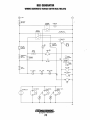
BED Generator Wiring Schematic ............................72
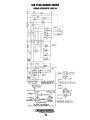
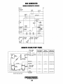
Remote Start/Stop Panel Wiring Diagram ................72
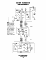
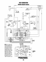
BED Generator Wiring Diagram ................................73
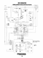
BED Generator Wiring Diagram ................................74
BED Generator Wiring Schematic ............................75
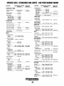
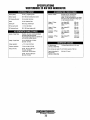
Generator Specifications..........................................76
Special Tools· Generator .........................................78
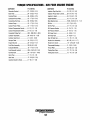
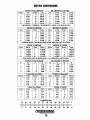
Metric Conversions ..................................................79
Index..........................................................................80
Engines & Generators
1
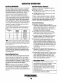
INTRODUCTION
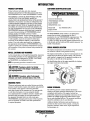
PRODUCT SOFTWARE
CUSTOMER IDENTIFICATION CARD
Product software (tech data, parts lists, manuals,
brochures and catalogs) provided from sources other than
WESTERBEKE are not within WESTERBEKE'S control.
/ ....'WESTERBEKE
I
WESTERBEKE CANNOT BE RESPONSIBLE FOR THE
CONTENT OF SUCH SOFTWARE, MAKES NO
WARRANTIES OR REPRESENTATIONS WITH RESPECT
THERETO, INCLUDING ACCURACY, TIMEUNESS OR
COMPLETENESS THEREOF AND WILL IN NO EVENT
BE UABLE FOR ANY TYPE OF DAMAGE OR INJURY
INCURRED IN CONNECTION WITH OR ARISING OUT
OF THE FURNISHING OR USE OF SUCH SOFTWARE.
Customer Identification
WESTERBEKE OWNER
MAIN STREET
HOMETOWN, USA
Model82B
Expires 9/1/99
WESTERBEKE customers should also keep in mind the
time span between printings ofWESTERBEKE product
software and the unavoidable existence of earlier
WESTERBEKE manuals. Product software provided with
WESTERBEKE products, whether from WESTERBEKE
or other suppliers, must not and cannot be relied upon
exclusively as the definitive authority on the respective
product. It not only makes good sense but is imperative
that appropriate representatives of WESTERBEKE or the
supplier in question be consulted to determine the accuracy
and currentness of the product software being consulted by
the customer.
Ser. #OOOOO-D911
The WESTERBEKE serial number is an alphanumeric
number that can assist in determining the date of
manufacture of your WESTERBEKE engine/generator. The
first character indicates the decade (A=1960s, B=1970s,
C=1980s, D=1990s), the second character represents the year
in the decade, and the fourth and fifth number represents the
month of manufacture.
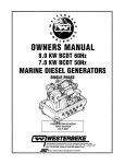
SERIAL NUMBER LOCATION
The engine and generator serial numbers and model numbers
are located on a decal on the generator housing.
NOTES, CAUTIONS AND WARNINGS
The engine serial number can also be found stamped into the
engine block just above the injection pump. The generator
serial number is stamped into the generator housing on the
flat surface on the left side of the generator.
As this manual takes you through the disassembly, inspection
and assembly procedure of your engine/generator, critical
information will be highlighted by NOTES, CAUTIONS,
and WARNINGS. An explanation follows:
An identification plate on the engine manifold also displays
NOTE: An operating procedure essential to note.
the engine model and serial number.
A CAUTION: Procedures, which if not strictly
GENERATOR
10 DECAL
observed, can result in the damage or destruction of
your engine/generator.
MODEL &
SERIAL
NUMBER
A WARNING: Procedures, which if not properly
followed, can result in personal injury or loss of life.
ORDERING PARTS
Whenever replacement parts are needed, always provide the
generator model number, engine serial number, and generator
serial number as they appear on the silver and black
name-plate located on the generator end. You must provide
us with this information so we may properly identify
your engine/generator. In addition, include a complete part
description and part number for each part needed (see
the separately furnished Parts List). Also insist upon
WESTERBEKE packaged parts because will fit or generic
parts are frequently not made to the same specifications
as original equipment.
ENGINE OVERHAUL
The following sections contain detailed information
relating to the proper operation characteristics of the major
components and systems of the engine. Included are
disassembly, inspection and reassembly instructions for the
guidance of suitable equipped and staffed marine engine
service and rebuilding facilities. The necessary procedures
should be undertaken only by such facilities.
Additional detailed information and specifications are
provided in other sections of this manual, covering the
generator, alternator, starter motor, engine adjustments,
cooling pumps, etc.
Engines & Generators
2
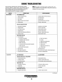
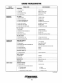
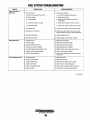
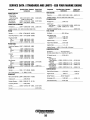
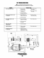
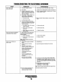
ENGINE TROUBLESHOOTING
The following troubleshooting chart describes certain
problems relating to engine service, the probable causes of
these problems, and the recommendations to overcome
these problems.This chart may be of assistance in
determining the need for an engine overhaul.
PROBLEM
HARD STARTING
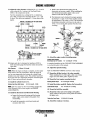
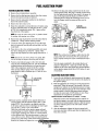
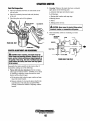
NOTE: The engine's electrical system is protected by a 20ampere manual reset circuit breaker. The preheat solenoid is
mounted on the same bracket.
PROBABLE CAUSE
VERIFICATION/REMEDY
LOW CRANKING SPEED
1. Engine oil viscosity too high.
1. Replace engine oil with less viscous oil.
2. Run-down battery.
2. Recharge battery.
3. Worn battery.
3. Replace battery.
4. Battery terminals loosely connected.
4. Clean terminals and correct cables.
5. Defective starter.
5. Repair or replace starter.
DEFECTIVE INJECTION SYSTEM
1. Air trapped in fuel passage.
1. Bleed air from fuel system.
2. Clogged fuel filter.
2. Clean or replace filter.
3. Low injection pressure.
3. Adjust injection pressure.
4. Inadequate spray.
4. Clean or replace nozzle.
5. Injection pump delivering insufficient fuel.
5. Repair or replace injection pump.
6. Injection too early.
6. Adjust injection timing.
MAIN ENGINE TROUBLES
1. Low compression.
a. Incorrect valve clearance.
a. Adjust valve clearance.
b. Inadequate contact of valve seat.
b. Lap valve.
c. Valve stem seized.
c. Replace valve and valve guide.
d. Broken valve spring.
d. Replace valve spring.
e. Compression leaks through cylinder head gasket.
e. Replace gasket.
/. Piston ring seized.
/. Replace piston and piston ring.
g. Worn piston ring and cylinder.
LOW OUTPUT
g. Overhaul engine.
2. Burnt glow plug.
2. Replace glow plug.
3. Faulty glow plug operation.
3. Correct lead wire connection, check preheat solenoid.
4. Incorrect governor lever position.
4. Set lever to starting position.
LOW COMPRESSION
See HARD STARTING
INJECTION SYSTEM OUT OF ADJUSTMENT
1. Incorrect injection timing.
1. Adjust injection timing.
2. Insufficient injection.
2. Repair or replace injection pump.
3. Low injection pressure.
3. Check injection nozzle and adjust pressure.
INSUFFICIENT FUEL
1. Air trapped in fuel system.
1. Check and retighten connector.
2. Clogged filter.
2. Clean or replace filter.
3. Contaminated fuel tank.
3. Clean tank.
INSUFFICIENT INTAKE AIR
1. Clogged air intake silencer.
1. Clean or replace air cleaner.
(continued)
Engines & Generators
3
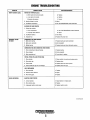
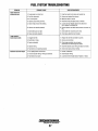
ENGINE TROUBLESHOOTING
PROBABLE CAUSE
PROBLEM
LOW OUTPUT (cont.)
VERIFICATION/REMEDY
OVERHEATING
1. Low coolant level.
EXCESSIVE OIL
CONSUMPTION
1. Add coolant.
2. Loose V-belt.
2. Adjust or replace V-belt.
3. Incorrect injection timing.
3. Adjust injection timing.
4. Low engine oillevel.
6. Add engine oil.
OIL LEAKAGE
1. Defective oil seals.
1. Replace oil seals.
2. Broken gear case gasket.
2. Replace gasket.
3. Loose gear case attaching bolts.
3. Retighten bolts.
4. Loose drain hose attachment.
4. Retighten banjo bolt and secure.
5. Loose oil pipe connector.
5. Retighten oil connections.
6. Broken rocker cover gasket.
6. Replace gasket.
7. Loose rocker cover attaching bolts.
7. Retighten attaching bolts.
OIL LEVEL RISING
1. Dead cylinder,.
1. Check compression.
2. Displaced or twisted connecting rod.
2. Replace connecting rod.
3. Worn piston ring.
3. Replace ring.
4. Worn piston or cylinder.
4. Replace piston and rebore cylinder.
OIL LEVEL FALLING
EXCESSIVE FUEL
CONSUMPTION
1. Defective valve stem seal.
1. Replace valve stem seal.
2. Worn valve and valve guide.
4. Replace a valve and valve guide.
ENGINE BODY TROUBLES
1. Noisy knocking.
1. See KNOCKING.
2. Smoky exhaust.
2. See SMOKY EXHAUST.
3. Moving parts nearly seized or excessively worn.
3. Repair or replace.
4. Poor compression.
4. See LOW COMPRESSION; HARD STARTING.
5. Improper valve timing.
5. Adjust.
6. Improper valve clearance.
6. Adjust.
INSUFFICIENT INTAKE AIR
1. Air intake obstructed.
1. Remove obstruction.
NOZZLE TROUBLES
SMOKY EXHAUST
1. Seized nozzle.
1. Replace.
2. Worn nozzle.
2. Replace.
IMPROPER FUEL
Replace with proper fuel.
FUEL LEAKS
Find fuel leaks.
WHITISH OR PURPLISH
1. Correct oil level.
1. Excessive engine oil.
2. Excessive rise of oil into combustion chamber.
a. Poor piston contact.
a. Check.
b. Seized piston ring.
b. Replace or clean.
c. Excessive piston-to-cylinder clearance.
c. Replace or correct.
(continued)
Engines & Generators
4
ENGINE TROUBLESHOOTING
PROBLEM
SMOKY EXHAUST (coni.)
PROBABLE CAUSE
VERIFICATION/REMEDY
WHITISH OR PURPLISH (coni.)
d. Worn valve stem and valve guide.
d. Replace.
e. Low engine oil viscosity.
e. Replace.
r.
r.
Excessive oil pressure.
Correct.
3. Injection timing is too late.
3. Adjust.
4. Insufficient compression.
4. See LOW COMPRESSION; HARD STARTING.
BLACKISH OR DARK GRAYISH
1. Engine body troubles.
a. Poor compression.
a. See LOW COMPRESSION; HARD STARTING.
b. Improper valve clearance.
ABNORMAL SOUND
OR NOISE
b. Adjust.
2. Insufficient intake air.
2. Clear intake.
3. Improper fuel.
3. Replace with proper fuel.
CRANKSHAFT AND MAIN BEARING
1. Badly worn bearing.
1. Replace bearing and grind crankshaft.
2. Badly worn crankshaft.
2. Grind crankshaft.
3. Melted bearing.
3. Replace bearing and check lubrication system.
CONNECTING ROD AND CONNECTING ROD BEARING
1. Worn connecting rod big end bearing.
1. Replace bearing.
2. Worn crankpin.
2. Grind crankshaft.
3. Bent connecting rod.
3. Correct bend or replace.
PISTON, PISTON PIN, AND PISTON RING
1. Worn cylinder.
1. Rebore cylinder to oversize and replace piston.
2. Worn piston pin.
2. Replace piston.
3. Piston seized.
3. Replace piston and rebore cylinder.
4. Piston seized and ring worn or damaged.
4. Replace piston and rings.
VALVE MECHANISM
ROUGH OPERATION
1. Worn camshaft.
1. Replace.
2. Excessive valve clearance.
2. Adjust.
3. Worn timing gear.
3. Replace.
INJECTION PUMP SYSTEM
1. Uneven injection.
1. Adjust injection or replace parts.
2. Worn delivery valve.
2. Replace.
3. Inadequate injection nozzle spray.
3. Replace injection nozzle.
(continued)
Engines & Generators
5
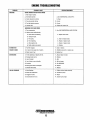
ENGINE TROUBLESHOOTING
PROBLEM
KNOCKING
PROBABLE CAUSE
VERIFICATION/REMEDY
ENGINE KNOCKS WITHOUT MUCH SMOKE
1. Main engine troubles.
a. Overheated cylinder.
a. See OVERHEATING; LOW OUTPUT.
b. Carbon deposits in cylinder.
b. Clean.
2. Too early injection timing.
2. Correct.
3. Too high injection pressure.
3. Correct.
4. Improper fuel.
4. Replace with proper fuel.
KNOCKING WITH DARK SMOKE
1. Poor compression.
1. See LOW COMPRESSION; HARD STARTING.
2. Injection pump malfunctioning.
a. Check valve worn/sticking.
a. Replace check valve.
3. Improper nozzle.
a. Poor spray.
a. Clean or replace nozzle.
b. Poor chattering.
b. Repair or replace nozzle.
C.
After-injection drip.
c. Repair or replace nozzle.
d. Nozzle needle valve seized.
INTERMITIENT
EXHAUST SOUND
OVERHEATING
LOW OIL PRESSURE
d. Replace.
1. Fuel filter clogged.
1. Clean or replace.
2. Air leak in fuel supply side of system.
2. Retighten pipe joints or replace pipe.
3. Water mixed in fuel
3. Replace fuel.
1. V-belt slackening or slippery with oil.
1. Adjust, replace or clean.
2. Damaged water pump.
2. Replace.
3. Lack of coolant
3. Add.
4. Low oil level or poor oil quality.
4. Add or change.
5. Knocking.
5. See KNOCKING.
B. Moving parts seized or damaged.
B. Replace.
7. Defective thermostat.
7. Replace.
1. Wom Bearings.
1. Engine overhaul replace bearings.
2. Relief valve malfunction.
2. Overhaul oil pump.
3. Clogged oil cooler.
3. Repair.
4. Diesel dilution of the oil.
4. Injection pump repair.
Engines & Generators
6
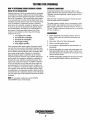
TESTING FOR OVERHAUL
HOW TO DETERMINE ENGINE OVERHAUL PERIOD
Cause of Low Compression
OVERHAUL CONDITIONS
Compression pressure tends to increase a little in a new
engine until piston rings and valve seats have been broken in.
Thereafter, it decreases gradually with the progress of wear
of these parts.
Generally, the time at which an engine should be overhauled
is detennined by various conditions such as lowered engine
power output, decreased compression pressure, and increased
fuel and oil consumption. The lowered engine power output
is not necessarily due to trouble with the engine itself, but is
sometimes caused by injector nozzle wear or injection pump
wear. The decrease in compression pressure is caused by
many factors. It is, therefore, necessary to determine a cause
or causes on the basis of data produced by periodic inspection and maintenance. Oil analysis on a seasonal basis is a
good means of monitoring engine internal wear. When
caused by worn cylinders or piston rings, the following
symptoms will occur:
1
2
3
4
5
When decrease of compression pressure reaches the repair
limit, the engine must be overhauled.
The engine requires overhaul when oil consumption is high,
blowby evident, and compression valves are at minimum or
below. Engine compression should be 30 kg/cm2, 427 psi at
200 rpm. Cylinder compression should not vary by more than
42.7 psi (3.0 kg/Cm2J.
DISASSEMBLY
Low engine power output
Increased fuel consumption
Increased oil consumption
Hard engine starting
Noisy engine operation
1. Before disassembly and cleaning, carefully check for
defects which cannot be found after disassembly and
cleaning.
2. Drain water, fuel and oil before disassembly.
3. Clean or wash the engine exterior.
4. Do not remove or disassemble the parts that require no
disassembly.
These symptoms often appear together. Symptoms 2 and 4
can result also from excessive fuel injection, improper injection timing, and wear of plugs and nozzles. They are caused
also by defective electrical devices such as the battery, alternator, starter and glow plugs. Therefore it is desirable to
judge the optimum engine overhaul time by the lowered
compression pressure caused by worn cylinders and pistons
plus increased oil consumption. Satisfactory combustion is
obtained only under sufficient compression pressure. If an
engine lacks compression pressure, incomplete combustion
of fuel will take place even if other parts of the engine are
operating properly. To determine the period of engine overhaul, it is important to measure the engine compression pressure regularly. At the same time, the engine speed at which
the measurement of compression pressure is made should be
checked because the compression pressure varies with engine
rpm. The engine rpm can be measured at the front end of the
crankshaft.
5. Perform disassembly in a proper order using proper tools.
Keep disassembled parts in order. Apply oil when necessary. Take special care to keep the fuel system parts from
intrusion of dust and dirt.
6. Carefully check gaskets, packings and oil seals even if checking is not specified. Replace with new ones if defective.
NOTE: To test engine compression see the ENGINE
ADJUSTMENT section of this manual.
Engines & Generators
7
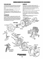
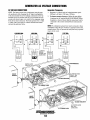
ENGINE/GENERATOR DISASSEMBLY
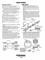
PROPULSION ENGINE
GENERATOR
Unplug the instrument panel wiring harness. Drain the transmission fluid and the transmission oil cooler hoses, Detach
the oil cooler hoses and unbolt the transmission from the
engine.
Drain or pump out all the engine oil and drain the coolant
from the engine and engine hoses.
Disconnect the AC wiring and unplug the engine's DC
wiring harness at the generator control panel. Disconnect the
battery cable connections and the engine ground cables.
Separate the exhaust hose at the water injected elbow and
disconnect the fuel supply and return lines.
NOTE: Label any lines, hoses or cables as you separate them.
For transmission service and maintenance refer to your
transmission manual. To rebuild a transmission contact your
WESTERBEKE dealer or an authorized transmission service
shop.
Drain the engine oil and the coolant from the engine.
Carefully support and then unbolt the generator backend
from the engine. See SPECIAL TOOLS - GENERATOR in
this manual.
Additional generator information will be found in the
GENERATOR section of this manual.
TRANSMISSION
If the transmission is not being rebuilt it should be visually
inspected. Flush out and pressure test the oil cooler and
replace the coolant hoses. Inspect and lubricate the gear shift
linkage and the propeller shaft coupling. Clean and repaint
the transmission and change the transmission fluid. Refer to
TRANSMISSIONS in this manual.
MARINE ENGINE
TABWASHER
THE ENGINE
SHOULD BE
SECURELY
MOUNTED ON
A SUITABLE
ENGINE STAND.
LABEL THE TERMINAL
CONNECTIONS AS
YOU DISCONNECT THE
WIRING HARNESS.
Engines & Generators
8
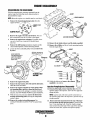
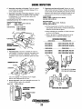
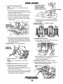
ENGINE DISASSEMBLY
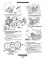
DISASSEMBLING THE MAIN ENGINE
With the transmission/or generator separated from the
engine, begin the following step by step procedure to
disassemble the engine.
NOTE: Mount the engine on a suitable stand or work bench.
1. Remove the transmission damper plate from the
C
engine flywheel.
O~~ ~
i~O~
DAMPER PLATE
BOLTS
o~t~0
2. Remove the engine oil cooler and oil hoses. Note oil
hose connections from the oil cooler to the engine.
3. Remove the engine heat exchanger. If possible, leave
one end of each hose connected to the part being
removed.
4. Remove the bell housing (propulsion engine) and the
circuit breaker/preheat solenoid mounting bracket.
11. Remove the air intake silencer and the intake manifold.
12. Remove the oil filter and the oil cooler mounting bracket
from the engine block.
5. Loosen the front crankshaft pulley bolt and remove the
flywheel.
WHEN REMOVING
THE MOUNTING BOLTS
LOCK THE FLYWHEEL
WITH A RING GEAR
BREAK TOOL
ONE BOLT DEVIATES !J'
FROM THE 6(J' SET UP
3
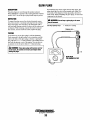
PLUNGER
SPRING _ _
O-RING _ _
PLUG_
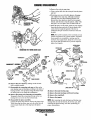
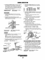
13. Unbolt the elbows and remove the exhaust
manifold in its entirety.
6. Remove the engine back plate.
7. Remove the start motor, drive belt and the alternator.
Label the wires and cables.
OIL
FILTER
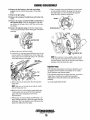
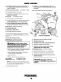
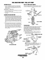
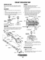
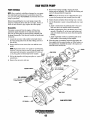
Injection Pumpnnjectors Disassembly
8. Remove the engine mounted raw water pump, adaptor mounting plate, and drive from the front cover.
14. Detach aU the high pressure injection lines from the
injection pump to the injectors. Leave the two upper line
clamps in place.
The drive is removed by turning in a counter clockwise
direction. See RAW WATER PUMP for parts breakdown.
NOTE: Cap the ends of the lines and the connections at
the injection pump and at the injectors to prevent entry of
foreign material.
9. With the hoses disconnected, remove the thermostat
housing and housing gasket, leaving the temperature
sender in place.
10. Remove the coolant recirculating pump. See
COOLANT RECIRCULATING PUMP for parts break-
15. Remove the fuel return line from the top of the injectors and from the fuel injection pump by removing the
four 12 mm attaching bolts. (Note the washer arrangement on fuel return line banjo bolts. Cap all the openings
on the fuel return line, injectors and injection pump.)
down.
Engines & Generators
9
ENGINE DISASSEMBLY
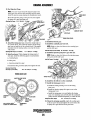
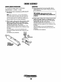
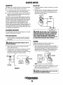
f. Once loosened, remove the holddown nuts and washers and carefully withdraw the pump from the drive
gear and engine so as to avoid losing the injection
pump drive key inside the timing case.
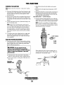
16. Remove the fuel injectors, dust seals and sealing
washers from the cylinder head using a 27mm deep
socket.
17. Remove the glow plugs.
18. Remove the crankcase breather hose and rocker arm
cover.
19. Remove the engine mounted fuel filter and fuel line to
the injection pump. (Note the arrangement of the sealing washers on the banjo bolts at fuel filter and the injection pump.)
20. Remove the injection pump. Scribe the mating marks
on the pump body flange and the timing gear case before
a. Remove the cover and the locknuts.
h. Loosen the two injection pump holddown nuts. Do not
remove entirely. The holddown nut on the engine side
of the pump can be loosened by using a 114" universal
socket and extension with ratchet.
NOTE: If an extractor is not available, replace the nut
on the injection pump shaft loosely and with a nylon
drift and hammer gently tap the injection pump shaft to
dislodge it from the keyed drive gear.
Injection Pump
If the injection pump requires servicing, it should be sent to
an injection service shop that can properly service a KikiZexel-Distributer type injection pump.
If the injection pump does not require servicing, it should be
wiped clean, covered and set aside until reassembly.
Adjustments to timing if needed can be performed after
assembly.
c. Remove the nut and lockwasher from the injection
pump shaft.
See FUEL INJECTION PUMP.
NOTE: Take care not to drop the nut and the washer
into the timing gear case.
d. Place the keyway on the injection pump shaft in the
12:00 position with the aid of the front crankshaft
pulley bolt before attempting to remove the
injection pump.
e. With the use of extractor Mazda tool #49 SE 01 157
apply sufficient pressure to loosen the pump from the
keyed gear. The loose holddown nuts will prevent the
pump from falling from the engine.
Engines & Generators
10
ENGINE DISASSEMBLY
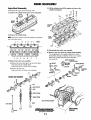
Engine Block Disassembly
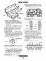
24. Lift the cylinder head off the engine and remove the
cylinder head gasket.
Disassemble the engine in the following order:
21. Remove the cylinder head rocker cover and gasket.
,
~j
ROCKER
COVER
~
®
HEAD
"GASKET
22. Remove the cylinder head.
NOTE: Loosen the cylinder head bolts equally and gradually
and in the order shown.
5
9
13
17
16
12
8
25. Disassemble the rocker arm assembly.
26. Remove each valve from the cylinder head assembly.
Use an appropriate valve spring compressor to aid in
disassembly. Arrange or label the valves so as to replace
them in the cylinder and guide from which they
were removed.
3
6
10
14
18
15
11
7
_®/
.
TAPER PIN RECESS
TAPER PIN HOLE .
23. Remove the rocker arm assembly.
a. Remove the valve stem caps so as not to lose them
when removing the cylinder head.
Label each cap as to which valve it belongs.
b. Remove the push rods.
Label each rod as to which valve it belongs.
~~.
® JAM NUT
SPRING WASHER
~HINGO SC~OP J~;~NING
RO~
ROCKER ARM ASSEMBLY
~BRACKET
..-~~
:¥
t
ROCKER
SPRING
~~
~
~~
VALVE SPRING RETAINER/
PUSHRODS~
OTAPPET
~
Engines & Generators
11
VALVE SPRING
REMOVAL
ENGINE DISASSEMBLY
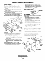
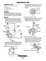
CRANKSHAFT
PULLEY
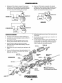
27. Remove the crankshaft pulley bolt with the aid of a 38
mm socket and draw the pulley off the front crankshaft.
--TIMING GEAR
CASE
INJECTION
PUMP DRIVE GEAR
TIMING GEAR COVER
Remove the timing gear cover and remove the injection pump washer, injection pump friction gear and
the injection pump drive gear.
29. Remove the camshaft gear.
a. Wedge a clean cloth between the camshaft gear and the
idler gear; remove the retaining bolt.
b. Remove the retaining plate, friction gear and, using a
suitable bearing puller, the camshaft gear.
30. Remove the idler gear.
REMOVING THE
CAMSHAFT GEAR
a. Remove the attaching nuts, thrust plate, idler gear and
idler gear hub.
31. Remove the crankshaft gear.
a. Remove the wave washer, the friction gear and,
using a suitable puller, remove the crankshaft gear
TIMING GEAR
and its key.
CASE
32. Tum the engine over and remove the oil pan
33. Loosen the oil pump assembly set screw at the side
of the block. Remove the oil pump. For oil pump
details see OIL PUMP.
34. Remove the timing gear case from the front of the
engine block. Discard the old gasket.
35. Remove the camshaft. Keep the engine turned
over when removing the camshaft. This allows the
valve lifters to seat on the block bosses away from
the cam lobes.
TIMING GEAR DIAGRAM
Engines & Generators
12
ENGINE DISASSEMBLY
b. Remove the wrist pin snap rings.
c. Using a nylon drift, drive the wrist pin from the piston
and rod.
d. Protecting your eyes with safety glasses, disengage
and withdraw the snap rings. Although mechanics
generally press out (and sometimes hammer out)
pistons pins, these practices should be discouraged.
Instead, take the time to heat the pistons, either with a
heat gun or on a hot plate. Pins will almost fallout.
e. While the piston is still warm, check for bore integrity.
.Insert the pin from each side. If the pin binds at the
center, the bore might be tapered; if the bore is
misaligned, the pin will click or bind as it enters the
far boss.
NOTE: The number stamped on the rod shank and cap
should correspond to the cylinder number. Sometimes
these numbers are scrambled or missing, and the
mechanic must supply them. Stamp the correct numberson the pads provided and, to prevent confusion,
deface the originals.
PISTON RING
REMOVING THE TIMING GEAR CASE
REAR OIL
SEAL
~ ~~' /~
""'-~"'-"
~~ MAl:
(\~
CRANKSHAFT GEAR ~\J~
SPRING
WASHER
SLiNGE.
CRANKSHAFT
PULL.EY
BEARING
~CAPS
~~~~
~~
~
@. ~~
~~
MAIN BEARINGS
36. Remove the rear oil seal by striking out the old seal
with a suitable mandrel.
37. Disassemble the connecting rod caps and line up the
main bearing caps and bearings according to the order of
bearing numbers. Also properly arrange the thrust washers, taking care not to change the combination.
40. Remove the main bearing caps.
41. Remove the main bearings and thrust bearings.
42. Remove the crankshaft.
43. Remove the tappets.
38. Remove the piston and connecting rod assemblies.
Temporarily install the connecting rod cap on the connecting rod so as to not mix the rods and caps.
39. Disassemble the piston assembly.
NOTE: After removing the main bearings and bearing caps
arrange them in order of removal. Do not mix caps. After
removing the thrust bearings, note their positioning for
proper reinstallation.
a. Using the piston ring remover, remove the piston rings.
While removing the piston rings, note the order they are
removed and which side of the ring faces the piston
crown.
Engines & Generators
13
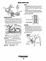
ENGINE INSPECTION
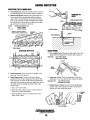
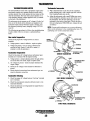
INSPECTING .THE CYLINDER HEAD
1. Visual Inspection. Check the cylinder head for cracks or
any other damage and, if necessary, repair or replace it.
REMOVING THE
INSERT
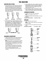
2. Distortion Inspection. Measure the cylinder head surface distortion with a straight edge and the thickness
gauge. Take 6 measuring positions as shown in the diagram. If the distortion exceeds permissible limit, replace
the cylinder head. (The head has no allowance for planing and must be replaced, not renewed.)
Position
1,2
ii, 4, 5, 6
Cylinder Head Distortion Limit
0.004 in (0.10mm)
0.010 in (0.25mm)
SUITABLE PUNCH ~
REMOVE LOCATING DOWELS
BEFORE USING STRAIGHT-EDGE
FEELER GAUGE
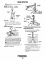
VALVE SPRING
DISTORTION INSPECTION
1. Free Length Check. Measure the free length pf the valve
spring and if free length is less than the limit, replace it.
3
Valve Spring
4--~~~~~~~~~~~~~H-
5
6
-~+-!,:=~~_~~~o......E~~~~:--
1
5
6
Inner 1.654 in (42mm)
Outer2.083 in (52.9mm)
VALVE
SPRING __
2
3. Insert Inspection. Check for cracks or damage on the
insert and, if detected, replace it.
4. Insert Replacement. To remove the insert, place a
suitable drift into the glow plug hole, then tap the drift
with a hammer. To install, set the insert in position and
insert the welch washer into the insert guide hole. Secure
the welch washer by tapping the raised center of the
welch washer.
a Use a new welch washer.
h. Insert the welch washer so that its convex surface is
toward the cylinder head gasket.
c. After installation, check to see if the insert is completely fixed in place.
2. Squareness Check. Check the squareness of the valve
spring and, if it is more than the limit, replace the spring.
Squareness Limit
Inner 0.049 in (1.25mm)
Outer 0.054 in (1.37mm)
3. Fitting Pressure Check. Check the valve spring fitting
pressure with a valve spring tester and, if the pressure is
less than the limit, replace the spring.
90° TEST ANGLE
Engines & Generators
14
ENGINE INSPECTION
NOTE: Measure the fitting pressure after compressing the
spring several times.
Spring Fitting Pressure
Inner
Fitting Length
1.49 in (37.8mm)
Fitting Pressure Limit 24.92 Ib (11.3kg)
VALVE GUIDE
INSTALLER
Outer
1.59 in (40.3mm)
66.36 Ib (30.1 kg)
VALVE SPRING
TESTER~
SPRING FITTING
PRESSURE
HEIGHT ABOVE
THE SPRING SEAT
0.65 in (16.5mm)
--+\---~
I
VALVE GUIDE
1. Inspecting clearance between valve and guide. Set a
dial gauge with a magnet and check the clearance
between the valve stem and the valve guide. If the clearance is more than the limit, replace the valve or valve
guide.
Clearance Limit 0.005 in (0.127 mm )
3. Dimension L. Check the protruding length of the valve
VALVE GUIDE CLEARANCE
stem, if it exceeds the specification, correct it as follows:
Dimension L Standard 1.890 in (48.0 mm)
a. When dimension L becomes larger 0 - 0.0202 in
(0 - 0.5 mm) from the standard, it is still possible to
use both the valve and the cylinder head.
2. Valve guide replacement. To remove the valve guide,
press out the valve guide towards the combustion chamber side, using the valve guide installer (49 0636 165A).
Again using the valve guide installer, press in the valve
guide into the cylinder head until the valve guide height
reaches the indicated scale on the valve guide installer.
VALVE SEAT
. INSERT
NOTE: Be sure to press in the valve guide so that the
inside chamber on the valve guide end faces to the
combustion chamber side. After the pressure fit, check the
length of the protruding portion of the valve guide.
Protrusion Standard
b. When dimension L becomes too large 0.20 - 0.059 in
(0.5 - 1 5 mm) from the standard, adjust the
dimension L to the standard by adding some washers
(inner diameter 0.504 in (12.8 mm), outer diameter
1.535 in (39 mm) between the lower spring seat and
the cylinder head.
0.650 in (16.5mm)
c. When dimension L becomes too large (more than
0.059 in(1.5mm) from the standards, replace the
valve's seat.
Engines & Generators
15
ENGINE INSPECTION
'/:,.,-.. _ SEAT INSERT
J:HECKING VALVE STEM WEAR
VALVE SEAT
d. Check for contact between the valve and valve seat
by applying a thin coat of Prussian Blue (or Redlead)
on the valve seat contact face, then insert the valve into
the valve guide and press fit the valve on the valve seat.
NOTE: Do not rotate the valve!
CONTACT FACE
1. Valve Seat Angle. Valve seat angle is 45° and 30°
respectively for intake and exhaust sides. The standard
contact width of the valve seat is 0.079 in (2.0 mm) for
both intake and exhaust sides. If the valve margin is less
than the permissible limit, replace the valve.
2. Refacing the Valve and Valve Seat. Reface in the following order:
a. Reface the valve with a valve grinder to the specified
angle.
h. Reface the valve seat with a valve seat cutter while
checking the contact between the valve and the valve
seat.
NOTE: Reface the valve seat taking care that the valve
seat contacts the center position of the valve.
Valve Seat Angle
Valve Seat Width
INTAKE
45· Intake, 30· Exhaust
0.079in (2.0mm) Intake and Exhaust
~~
CONTACT FACE
I
...... ··4.5~"'if' ::,.:)""",.\"." .
e. Check if the valve seat contact face contacts the center
position of the valve contact face. If the contact position is not centered, recut and surface the valve seat
and valve.
4. Stem Wear Inspection. If the valve stem is bent or its
diameter is less than the limit, replace the valve.
Stem diameter limit
Intake
Exhaust
1.25 in (31.7 mm)
EXHAUST
0.351 in (8.904 mm)
0.350 in (8.884 mm)
c. Reface the valve and valve seat with a valve tapping
compound.
d. Remeasure dimension "L".
e. Adjust dimension "L" to the standard by adding some
washers between the lower spring seat and cylinder
head.
Engines & Generators
16
ENGINE INSPECTION
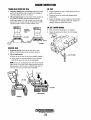
ROCKER ARM
CYLINDER BLOCK
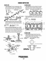
1. Visual Inspection. Check each component part of the
1. VISUal Inspection. Check the cylinder block for cracks
and damage. If necessary, repair or replace it entirely.
rocker arm assembly for cracks or other damage. Check
if the oil passages of the rocker arm ana shaft are clogging and, if necessary, repair or replace the rocker arm.
1m-JAM NUT
SPRING WASHER .
_~~ ~
~>@J ~
Q;;II
A. _____ ADJ. SCREW
~-~BUSHING'~
. .
ROCKER SHAFT ~
SUPPORT ~~
~~
~-_B:e.)e_~
~C>
~o
_~
RETAINING
RING
'Q~e~a~&
w'
JII "
!to If , "
t
ROCKER
_~
BEFORE INSPECTING
\
lr
:o~
Check to see that oil or cooling water passages are not
clogged and, if clogged, remove ~ith compressed air or a
wire probe.
REMOVING LOCATING DOWELS
"
~-CJtt
TAPER PIN RECESS
SPRING
,0 ""~.~~
.
---=-------.... ()
ROCKER ARM ASSEMBLY
2. Distortion Inspection. Check the gasket face distortion
of the cylinder block and if it exceeds the limit, repair or
replace it.
\
Distortion limit: 1,2
0.004 in (0.10mm)
1
3,4,5,6 0.010 in (0.25mm)
SCALLOP
2
2. Inspecting clearance between rocker arm and shaft.
Check the clearance between the rocker arm and shaft
and, if it exceeds the limit, replace the rocker arm bushing or shaft.
Clearance Standard
Limit
6
4----J~~~"""
0.0006 - 0.0024 in (0.016 - O.061mm)
0.0028 in (0.07mm)
3. Rocker Arm Bushing Replacement. Using a suitable
mandrel and press, press out the old bushing. Aligning
the oil passages of the rocker arm bushing, press the new
bushing into the rocker arm. After the rocker arm bushing
has been replaced, ream the bushing bore with a spiral
expansion reamer so that the clearance between the bushing and shaft becomes equal to' the standard clearance.
CYLINDER LINER
1. Wear Inspection. Measure the liner bore at three
positions of upper, middle and lower portions with a
cylinder gauge in X-X and Y-Y directions as shown. If
wearing exceeds the limit, replace the liner.
Cylinder Liner Bore
Wear Limit
3.7412 - 3.7422 in (95.025 - 95.050mm)
0.008 in (0.20 mm)
y
REPLACING
THE BUSHING
X--!+-- --t+--X
x -X IS THE THRUST DIRECTION
~
CYLINDER LINER ~~_~
WEAR INSPECTION
Engines & Generators
17
CYLINDER LINER
ENGINE INSPECTION
2. Cylinder Liner Replacement. Hydraulic press or similar
c. Measure the piston diameter at 90° (perpendicular) to
the pin bore axis and 0.866in (22mm) below the piston
top.
SUB COMBUSTION
device is needed.
a. Attach the cylinder liner puller and installer to the .
lower rim of the cylinder liner, then press out the liner.
CHAMBER
h. Check for scratches on the cylinder block side and, if
any, remove them by using extremely fine emery paper
with engine oil.
c. To install the liner, apply engine oil on the cylinder
block bore and the liner exterior, then set the liner on
the cylinder block. Using the cylinder liner puller and
installer, press the liner into the cylinder block.
NOTE: Press the liner in straight. When press fitting the
liner, keep the pressure within a range of2,200-6,600lb.
Standard Piston Diameter
2. Piston Ring Inspection. Check the piston ring for
Measure the liner protrusion and correct it if necessary.
Protrusion Limits
3.7381 - 3.7399 in (94.967 - 94.993mm)
breaks, seizure and wear and, if any of these conditions
exist, replace the ring. Check the clearance between the
piston ring and the ring groove and, if it exceeds the
limit, replace the ring.
0.0040 - 0 in (0.101 - 0 mm)
LINER
PISTON AND PISTON RING
1. Visual Inspection. Check the sliding surface and
ring groove of the piston for wear, scratches or any
other damage.
a. Inspecting the clearance between the piston and the
cylinder liner.
h. Check the clearance between the piston and the cylinder liner by measuring the cylinder bore and the piston
diameter and, if the clearance exceeds the limit, replace
the cylinder liner and the piston.
PISTON RING
Side Clearance Limit
0.012 in (O.30mm)
3. Inspecting the piston ring end gap. Position the piston
ring into the bottom of the cylinder liner. Measure the
piston ring end gap and, if it exceeds the limit, replace the
ring. Be sure to position the piston ring below the ring
sliding surface of the cylinder liner.
DIAL INDICATOR
GAUGE
Side Clearance 0.0017 - 0.0028 in (0.032 - 0,083 mm)
Piston Ring End Gap Limit
Engines & Generators
18
0.591 in (1.5mm)
ENGINE INSPECTION
CONNECTING ROD
1. Visual Inspection. Check the connecting rod for cracks
PISTON PIN
or other damage and, if necessary, replace it.
CLEARANCE
BETWEEN THE
PISTON PIN AND
SMALL END BUSHING
4. Small end bushing replacement. Using a press, press
out the old bushing. Align the oil passages of the connecting rod and the small end bushing; press in the new bushing to the connecting rod bore. After a small end bushing
has been replaced, ream the bushing bore to obtain the
specified clearance between the small end bushing and
the piston pin.
CONNECTING
ROD
PRESS
LARGE
END
BUSHING
CAP
REMOVING THE
SMALL END
BUSHING
'~.AQIt-- ALIGNING
PRESSING IN
THE NEW
BUSHING
MARKS
SMALL END
OIL HOLES
{7
2. Bend Inspection. Using a connecting rod aligner, check
the bend and twist of the connecting rod and, if exceeding
the limit, repair it with a press or replace it.
Bend Limit
NOTE: When reaming the bushing, correctly insert the
reamer in the bushing. In order to prevent unevenness on
the bushing surface, the reaming should always be made
in the cutting direction. Make certain the reamer is
stopped at different positions at all times.
0.002 in per 3.9 in (0.05 mm per 100 mm)
5. Inspecting connecting rod side play. Check the connecting rod side play with the dial gauge and, if it exceeds the
limit, replace the connecting rod and crankshaft.
Side Play Limit 0.016 in (0.40 mm)
,
3. Inspect the clearance between the piston pin and
smaIl end bushing. Check the clearance between the
piston pin and the small end bushing and, if it exceeds the
limit, replace the piston pin or small bushing.
Clearance Standard:
Clearance Limit:
0.0005 - 0.0015 in (0.012 - 0.039 mm)
0.002 in (0.05 mm)
. CONNECTING ROD
SIDE PLAY TEST
Engines & Generators
19
ENGINE INSPECTION
3. Inspecting crank pin and journal. Support the crank-
6. Inspecting connecting rod bearing. Check the connecting rod bearing for peeling and thennal damage. If it is
shaft on both ends using V-blocks. Measure the diameter
of each crank pin and crankshaft main journal and, if the
diameter is less than the limit, refinish the crank pin and
main journal to size for the next undersize bearing.
severe, replace the bearing.
7. Inspecting connecting rod bearing clearance. Using the
plastigauge, measure the oil clearance of the connecting
rod bearing and, if it exceeds the limit, replace the
connecting rod bearing.
Crank pin diameter
Standard 2.40601 - 2.4065 in (61.112- 61.125 mm)
Wear limit 0.002 in (0.05 mm)
Connecting Rod Cap Torque 56.41- 57.86 ft-Ib (7.8 - 8.0 m-kg)
Main journal diameter
Standard 2.9848 - 2.9853 in (75.812 - 75.825 mm)
Wear limit 0.002 in (0.05 mm)
Connecting Rod Bearing Clearance
Standard:
0.0005 - 0.0012 in (0.012 - 0.031 mm)
Limit:
0.0020 in (0.05mm)
Undersize Bearing:
a. For the measurement on both the crank pin and the
main journal, measure them at vertical and horizontal
directions on front and rear places.
b. When refinishing the crankshaft, it's finish to Rlmm
as shown in the diagram.
0.010 in (0.254 mm)
0.020 in (0.508 mm)
0.030 in (0.762 mm)
c. Refer to the chart for refinishing dimensions of the
crankshaft where an undersize bearing is used.
REFINISHING DIMENSIONS
Undersize bearing
~
0
'
INSPECTING
BEARING CLEARANCE
CRANKSHAFT
'"
0.01 in (0.254 mm)
0.02 in (0.508 mm)
0.D3 in (0.762 mm)
~~
2.9748 - 2.9753 in (75.558 - 75.571 mm)
2.9648 - 2.9675 in (75.304- 75.317 mm)
2.9578 - 2.9554 in (75.050 • 675.063 mm)
Crankpin diameter
Undersize bearing
0.D1 in (0.254 mm)
0.D2 in (0.508 mm)
0.D3 in (0.762 mm)
1. Visual Inspection. Check the crankshaft for cracks or
other damage. If cracking is suspected, thoroughly clean
Main journal diameter
2.3964 - 2.3965 in (60.868·60.871 mm)
2.3874- 2.3865 in (60.604 - 60.617 mm)
2.3760·2.3765 in (60.350·60.363 mm)
the crankshaft and perfonn a magnafiux check of the
crankshaft. If any cracks are detected, replace the crankshaft.
MAGNAFLUX TEST
CRANKSHAFt_
R1'o.146/O.157"(3.71/3.99mm)
R2'O.126/O.142"(3.20/3.61mm)
--
Check for clogging of oil passages and, if clogged,
remove with compressed air or a wire.
2. Runout inspection. Check the crankshaft runout and, if it
exceeds the limit, replace the crankshaft.
Runout Limit
0.0020 in (0.05 mm)
CRANKSHAFT RUNOUT
INSPECTION
INSPECTING THE CRANKSHAFT
RUNOUT
Engines & Generators
20
ENGINE INSPECTION
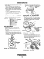
4. Inspecting crankshaft end play. Check the end play of
3. Inspecting camshaft journal. Check the camshaft
journal and, if wearing exceeds the limit, replace the
camshaft.
the crankshaft and, if the end play exceeds the limit,
replace the thrust washer with 0.007 in (0.178 mm) oversize. Crankshaft end play is measured by setting a dial
gauge on the rear end of the crankshaft and moving the
crankshaft in the axial direction.
Crankshaft End Play Standard:
Crankshaft End play limit:
No.1
No.2
NO.3
No.4
0.0055 - 0.0154 in (0.14 - 0.39 mm)
0.0157 in (0.40 mm)
Diameter of Joumal
2.0437 - 2.0449 in (51.910 - 51.940 mm)
2.0339 - 2.0350 in (51.660 - 51.690 mm)
2.0240 - 2.0252 in (51.410 - 51.440 mm)
2.0142 - 2.0154 in (51.160 - 51.190 mm)
Wear Limit
0.008mm
(0.0003 in)
4. Inspecting camshaft oil clearance. Check the clearance
between the camshaft journal and the camshaft support
bore as follows:
a. Measure the camshaft journal diameter and the
camshaft support bore.
MAIN BEARING
1. Inspecting main bearing. Check the main bearing
for peeling, seizure or fusion and, if necessary, replace
the bearing.
b. Calculate the clearance and replace the camshaft or
cylinder block if the clearance exceeds the limit.
2. Inspecting main bearing clearance~ Using the
plastigauge, measure the oil clearance and, if it exceeds
the limit, replace the main bearing.
Oil clearance limit
0.0057 in (0.145 mm)
5. Checking camshaft alignment, and, if it exceeds the
limit, replace the camshaft.
Maximum allowable runout 0.0031 in (0.08 mm)
6. Inspecting camshaft end play.
a. Install the thrust plate, camshaft gear,
PLASTIGAUGE
Lock Bolt Torque (19mm socket)
Oil Clearance Standard:
Oil Clearance Limit:
frictio~ear,
lock plate and camshaft gear lock bolt on the camshaft.
b. Tighten the lock bolt to the specified torque.
46 - 691b/ft (6.4 - 9.5 kg/m)
c. Measure the clearance between the thrust plate and
camshaft gear. If it exceeds the limit, replace the thrust
plate.
0.0023 - 0.0035 in (0.059 - 0.090 mm)
0.005 in (0.12 mm)
End play limit
CAMSHAFT
0.0118 in (0.3 mm)
CAMSHAFT
GEAR
1. Visual Inspection. Check the camshaft for cracks and
damage. If necessary, replace the camshaft.
NOTE: If the damage is slight, you may be able to correct
the camshaft with an oil soaked fine emery grindstone.
Take special care to not damage the original cam form.
2. Inspecting cam height. Measure the cam height and, if it
is less than the limit, replace the camshaft.
Cam height limit:
1.6724 in (42.478 mm)
IDLER GEAR BUSHING AND IDLER GEAR SPINDLE
1. Visual inspection. Check for damage on the bushing
inner surface of the idler gear and the spindle sliding surface and, if necessary, replace the idler gear or spindle.
Check the oil passage for clogging and, if necessary,
clean the passage with compressed air or wire.
INTAKE AND EXHAUST CAM
r::w-
CAM "ElGKT
2. Inspecting clearance between bushing and spindle.
Check the clearance between the idler gear bushing and
the spindle and, if it exceeds the limit, replace the idler
gear or spindle.
INSPECTING THE
CAMSHAFT
_~~~~\1
Clearance Standard:
Clearance Limit:
Engines & Generators
21
0.0013 - 0.0033 in (0.034 - 0.084 mm)
0.006 in (0.15 mm)
ENGINE INSPECTION
TAPPET
1. Visual inspection. Check the tappet for cracks and other
damage and, if damaged replace the tappet. Check for
abnormal wear of the portion of the tappets that contact
with the cam, and if anyone is abnormally worn, replace
the tappet.
2. Inspecting Clearance Between Tappet and Tappet
Bore. Check the clearance between the tappet and tappet
bore and, if the clearance is greater than the limit, replace
the tappet or cylinder block.
CHECKING
.CLEARANCE
Clearance Limit 0.0039 in (0.10 mm)
BETWEEN TUI: I\\f.oi ~l(\\~'t\
BUSHING
AND SPINDLE
CHECKING THE GEARS
1. Visual Inspection. Check each gear (idler gears, injection
pump drive gear, crankshaft gear, camshaft gear) for
cracks or other damage. If necessary, replace as required.
2. Inspecting end play of idler gear. Check the end play of
the idler gear with a dial indicator as shown. If it exceeds
the specified limit, replace the thrust plate or idler gear.
~
TAPPET CLEARANCE .~
.'
..
PUSH RODS
1. Visual Inspection. Check each push rod for damage to
eithfr end. If damage is severe, replace the push rod.
2. Bend Inspection. Check the push rod for bend and, if it
exceeds the limit, replace it. Place the push rod on a flat
surface and measure the clearance between the center of
the push rod and the flat surface. Replace the push rod if
the wear limit is exceeded.
Bend limit: 0.0075 in (0.19 mm)
TESTING THE .
PUSH ROD
JIJ')J,LLUr.ttuo
NOTE: Measure the end play after tightening the idler
gear attaching nuts to the specified torque value.
Thrust plate torque (1fl" socket) 17 - 231t-lb (2.3 - 3.2 kg/m)
Standard end play
0.0059 - 0.0118 in (0.15 - 0.30 mm)
3. Check backlash between gears. Check the backlash
between each gear with a dial indicator.
NOTE: Check the backlash after assuring that the idler
gear end play and the clearance between the idle gear
bushing and spindle are within the standard.
Backlash Standard
Backlash Limit
PUSH RODS
0.0039 - 0.0079 in (0.10·0.20 mm)
0.0118 in (0.30 mm)
Engines & Generators
22
ENGINE INSPECTION
TIMING GEAR COVER OIL SEAL
OIL PAN
1. Inspecting timing gear cover oil seal. Check the timing
gear cover and the lip of the oil seal for any damage. If
necessary, replace the cover or oil seal.
2. Oil seal replacement. To remove the oil seal, use the oil
seal puller and installer and pull out the oil seal. To
install, apply engine oil on the outside of a new oil seal,
then press fit the oil seal with oil seal puller and installer
until the installer comes in contact with the cover.
1. Scrape and clean any dirt or metal particles from the
inside of the oil pan.
2. Check the oil pan for cracks and damaged drain
plug threads
3. Inspect for damage (uneven surface) at the bolt holes
caused by the over torquing of the bolts. surfaces as
required. Repair or replace the oil pan.
OIL JET (UPPER BLOCK)
OIL SEAL
INSTALLER
TOOL
1. Make certain the oil passage is not clogged.
2.
.REAR OIL SEAL
1. Inspecting oil seal. Check the oil seal lip for wear,
fraying or other damage and, if necessary, replace it.
2. Oil seal replacement.
a. Strike out the old rear oil seal with a suitable mandrel.
b. Apply engine oil onto the outside of a new seal and
press fit the seal in the rear oil seal cap equally.
__ OIL JET VALVE
NOTE: In case the crankshaft is worn, the oil seal must be
fitted on the oil seal cap with its fitting position moved by
approximately O.1I81in (3mm) so that the seal does not
touch the worn down portion of the crankshaft.
OIL SEAL
INSTALLATION
REMOVAL
Engines & Gene;ators
23
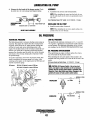
ENGINE ASSEMBLY
Reassembly Precautions
ENGINE ASSEMBLY
• Be careful not to mix bolts and nuts. Metric and S.A.E.
bolts are used on various engine assemblies.
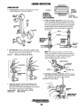
1. Install the valves in cylinder head. Using the valve
spring lifter arm and pivot, assemble the valve, lower
spring seat, oil deflector, inner valve spring, outer valve
spring, upper spring seat and taper sleeve in this order.
• During assembly, recheck clearances and insure that parts
are being assembled in their proper order and facing in the
correct direction in relation to the engine block, such as,
pistons, piston rings, bearings and bearing caps.
NOTE: The oil deflector should be installed on the intake
valve only.
• Apply lubricating oil to moving parts during assembly.
Insure that moving parts, when assembled on the engine,
rotate or slide and are not subject to binding or
excessive tension.
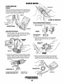
2. Assemble the rocker arm shaft, rocker shaft brackets
and rocker arms. Note that the front end of the rocker
shatt is identified by a pin protruding from the top and a
larger oil hole between the supply holes serving #1 and
#2 rocker arms. This pin fits a slot in the #1 rocker shaft
support which prevents the shaft from turning and cutting
off the lube oil to the rocker arms and valves. Use the following order of assembly:
a. Spring
d. Rocker
b. Rocker
e. Wave washer
f. snap ring
c. Rocker shaft support
• If there are mating marks scribed during disassembly,
reference them correctly for assembly.
• Use new gaskets, lockwashers, O-rings, etc.
• Tighten the holts and nuts on important parts of engine to
specified torques using a reliable torque wrench.
• Use liquid sealants when required on nuts, bolts and
gaskets. Refrain from using tape sealants.
NOTE: Also refer to Sealants and Lubricants in this manual.
,JAM NUT
TAPER
®.
~BUSHING
•
Be aware of these common problems that can occur during
assembly.
Insufficient Lubrication. Heavily oil sliding and
PI~
~
~
~
®
()
#1 ROCKER
_-"'II"IIlIJO
'-.... ...... ./SPRING
~
TAPER PIN RECESS
reciprocating parts, lightly oil head bolts and other fasteners,
except those that penetrate into the water jacket. These
WAVE WASHER
fasteners should be sealed with Permatex No.2 or the
high-tack equivalent.
SNAP
Reversed orientation. Most gaskets, many bolt washers, and
SUPPORT
TAPER PIN HOLE
--RING
all thermostats are asymmetrical.
3. Assemble the connecting rod, piston and piston rings.
Mechanical damage. Run fasteners down in approved
Arrange the piston and the connecting rod as shown and,
torque sequences and in three steps-II2, 213, and 111 torque.
using the piston pin installer, insert the piston pin through
Exceptions are torque-to-yield bolts and rocker arm shaft
the piston and connecting rod until the piston pin (wrist
fasteners. The former are torqued as indicated. The
pin) snap rings can be fitted. Fit the piston pin snap rings
latter-rocker shaft fasteners-should be brought down in very
to their respective grooves. Install the piston rings to ring
small increments, working from the center bolts out. Gaskets,
grooves on the piston with the inscription mark on ring
especially head gaskets, might be damaged during assembly,
upward using a suitable piston ring expander.
I
they should be positioned with great care.
i\~
AT 9(J' INTERVALS
TOP RING & OIL
EXPANDER SPRING
FRONT ...__.......-
FRONT OF PISTON
IS INDICATED BY
A BOSS ON THE
BOTTOM NEAR THE
OIL HOLE
\
•
TOP RING
~SECOND
-_ - 5 ~RING
0.............
CHECK THE PISTON RING
GAPS WITH CARE. NEW
RINGS ARE PACKAGED
WITH DETAILED INSTRUCTIONS
THAT OFTEN SUPERSEDE
THE SERVICE MANUAL.
24
OC~SHAfT/(@4sf5
ENGINE ASSEMBLY
PLACE A HEAW HAMMER AND
GENTLY PRESS DOWN WITH
THE FORCE OF YOUR HAND.
THE ENTIRE SURFACE SHOULD
BE COATED WITH FRESH LUBE OIL.
4. Main Bearings and Bearing Caps.
NOTE: Do not apply oil to the backsides of the main
bearing shells.
a. Fit the main bearings on the cylinder block and the
bearing caps respectively. Check that the oil ways align
perfectly with those in the block.
b. Fit the thrustwashers to the cylinder block so that the
oil grooves on thrustwashers face to crankshaft side.
c. Position the crankshaft to the cylinder block, being
careful not to drop the thrustwashers as the crankshaft
settles into place.
r
1
r
c. Install the caps to the connecting rods, ensuring that
the identification numbers on the cap and connecting
rod are matched.
~
mnN~~
Cap Torque (14 mm socket)
59 - 65 ft-Ib (8.2 - 9.Om-kg)
(install new connecting rod bolts)
THRUST WASHERS
d. Fit the thrust washer to the main bearing cap so that
the oil grooves on thrust washer face to crankshaft
side. Then install the main bearing cap to the cylinder
block with arrow mark of the main bearing cap facing
the crankshaft pulley side.
Main Bearing Cap Torque
8. Installation of the crankshaft.
a. Insert the tappets into the cylinder block. Apply engine
oil to the sliding face of the tappet.
"'-..../
11.0 -11.7 m-kg (80 - 85 ft-Ib)
FITTING THE
BEARING CAPS
b.Insert the camshaft into the cylinder block. Apply oil to
the camshaft joumal and bearing surfaces.
c. Install the camshaft thrust plate.
5.
NOTE: Ensure the crankshaft rotates smoothly after
installing.
Thrust Plate Torque (1/2 in socket) 11.6 -17.4 ft-Ib (1.6 - 2.4 m-kg)
9. Install the idler gear spindle. Align the oil passages of
the idler gear spindle and cylinder block.
6. Install the rear oil seal. Apply oil to the oil seal lip.
7. Install the piston and connecting rod assembly.
a. Place the piston rings so that the ring ends are
properly spaced around the circumference of the piston
as shown on the previous page.
b. Using a ring compressor, fit the piston into the cylinder
in the position as is shown. Apply oil onto the sliding
face of the piston and the cylinder bore.
Engines & Generators
25
ENGINE ASSEMBLY
10. Fuel Injection Pump.
NOTE: It is easier to first install the injection pump to the
timing gear case and the entire assembly onto the engine.
Install the injection pump aligning the identification marks.
Mount the injection pump on the gear case, then tighten
the pump drive gear attaching nuts.
Attaching Nut Torque 29 - 51 Mb (4.0 - 7.0 m/kg)
~'.
,.,-'
"
I
TIMING GEAR COVER
13. Install the friction gear.
14. Install the camshaft gear lock bolt.
11. Install the timing gear case. Attach the straight edge on
the cylinder block, then match the surfaces of the timing
gear case end and that of the cylinder block. If the gasket
protrudes from the mating surface, cut away the excess
with a knife.
Attaching Bolt Torque (1/2 in socket)
NOTE: Wedge a clean cloth between the camshaft gear
and the idler gear.
Lock Bolt Torque (19 mm socket) 46 - 69 ft-Ib (6.4 - 9.5 m-kg)
12 -17 Mb (1.6 - 2.4 m/kg)
15. Install the injection pump drive gear lock nut.
12. Install each gear. While aligning the timing mark of
each gear, install the following gears on each position:
a. Camshaft gear;
b. Idler gears;
c. Injection pump drive gear;
d. Install the idler gear thrust plate, then tighten the nuts.
Idler Gear Thrust Plate
Nut Torque (1/2 in socket)
16.6 - 23.1 ft-Ib (2.3 - 3.2 m-kg)
TIMING GEAR CASE
INJECTION PUMP DRIVE
GEAR
16. Install the oil deflector on the crankshaft.
17. Install the timing gear cover.
a. Install the bearing housing cover on the timing
gear cover.
b. Install the injection pump drive gear cover on the
timing gear cover.
c. Install the timing gear cover and tighten the timing
gear cover attaching nuts and bolts after the crankshaft
pulley has been installed temporarily to center the seal.
Timing Gear Cover Torque
LINE UP
GEAR TIMING
MARKS
KEY IS VERTICAL WHEN
ALIGNING THE TIMING MARKS.
11.6 -17.4 ft-Ib (1.6 - 2.4 m-kg)
18. Mount the oil pump assembly. Apply the sealing agent
on the set screw thread and tighten the screw. Ensure the
oil pump drive gear and the driven gear mesh.
CRANKSHAFT
GEAR
Engines & Generators
26
ENGINE ASSEMBLY
26. Position the cylinder head.
27. Insert the pushrod. Check if the push rod is securely set
in the tappet concavity.
19. Assemble the new gasket set (lower block).
a. Position the gasket ends A on the gaskets B and C.
b. Apply a silicon sealing agent on the mating surfaces of
the gasket and that between the cylinder block and the
timing gear case.
c. Install the lower block making certain the lower block
gasket is perfectly aligned. Tighten the bolts evenly.
. Lower block Bolt Torque(ll2 in socket)
~
~
INCORRECT
TAPPET'
12 - 17 ft-Ib (1.6 - 2.3 m-kg)
20. Install the oil pan gasket and the oil pan (sump).
CAM
Oil Pan Bolts Torque (9116 in socket) 12 -17 ft-Ib (1.6 - 2.3 m-kg)
. 21. Attach the back plate.
Back Plate Torque (9/16 in socket)
28. Position the valve cap on the top of the valve stem. It
should beset squarely on the valve stem.
29. Install the rocker arm assembly onto the cylinder
head. Remember that the end of the rocker shaft having
the pin occupying the slot in #1 rocker support points
toward the front (pulley) end of the engine.
30. Tighten the cylinder head bolts. Tighten the cylinder
head b?lts evenly in the sequence shown. After tightening
the cylInder head bolts, make certain the rocker arms
move smoothly.
23.9 - 35 ft-lb(3.3 • 4.8 m-kg)
22. Install the flywheel. Install the flywheel onto the rear end
of the crankshaft by placing it on the crankshaft and rotating it to properly align the mounting bolt holes. Install the
tabwasher and the attaching bolts. After torquing, bend
one tab against the flat of each attaching bolt.
Flywheel Bolts Torque (19 mm socket) 112 ft-Ib (15.5 m-kg)
Cylinder Head Bolts
Torque (3/4 in socket) 85 - 90 ft-Ib (11.8 -12.5 m-kg)
TABWASHER
23_ Install the raw water pump. Mount the raw water pump
on its adapter plate and assemble it to the engine. Do not
tighten.
24. Install the crankshaft pulley. Apply engine oil onto the
lip of the oil seal. Carefully slide the front crankshaft pulley onto the crankshaft ensuring that the key in the crankshaft and the keyway in the pulley mate properly. Apply
Loctite (high temperature) to the threads of the front
crankshaft pulley holddown bolt when installing it.
Ensure the flat washer is under the head of the bolt.
Front Crankshaft Pulley
Bolt Torque (38 mm socket) 253 - 289 ft-Ib (3~ - 40 m-kg)
--..
Engines & Generators
27
ENGINE ASSEMBLY
31. Adjust the valve clearance. Adjust the No.1, 2,3, and 6
. valves when the No. 1 piston is on Top Dead Center
(IDC) or the compression stroke.
c. Install a new thermostat and gasket (the old
thermostat can become a spare). When installing the
new thermostat and gasket, apply a thin coat of
sealant to both sides of the gasket.
Tum the crankshaft once, setting the No, 4 cylinder piston at TDC (compression) and adjust the No.4, 5, 7, and
8 valves. The valves are numbered 1 - 8 from front of the
engine.
d. The thermostat can be checked for proper operation
by placing it in a pan of cold water and then raising
the temperature of the water to a boil. The thermostat
should open noticeably (with travel on the order of
1/4 in - 112 in) and be fully opened when the water
is boiling.
WHEN NO.4 CYLINDER IS AT TOP DEAD CENTER
I 41NTAKE
4 EXHAUST
31NTAKE
EXHAUST 2
.
AIR BLEED
PETCOCK
/
f EXHAUST
2 INTAKE
I
WATERTEMP
SWITCH
NTAKE 1
~. EXHtUST
WHEN NO.1 CYLINDER IS ~T TOP DEAD CENTER
WATER TEMP
SENDOR
35. Attach the engine coolant circulating pump.
Coolant Pump Assembly
Bolts Torque (use 1/2" socket)
32. Adjust each valve's clearance by inserting a 0.012 in
(0.03 mm) feeler gauge between the rocker arm and the
valve stem.
Valve Clearance
1.6 - 2.3 m-kg (12 - 17 ft-Ib)
A complete breakdown of the COOLANT PUMP ASSEMBLY
is covered elsewhere in this manual.
36. Adjust the injection timing.
0.30 mm (.12 in) cold
Refer to INJECTION TIMING elsewhere in this manual.
NOTE: When the engine overhaul is complete, run the engine
under load to check its peiformance. Allow the engine to
cool to room temperature and retorque the cylinder head
holddown nuts and readjust valves. The cylinder head holddown bolts and valve adjustment should be rechecked again
after 50 hours and periodically thereafter.
37. Mount the oil filter bracket 1 oil cooler assembly.
When installing the new filter apply a thin coat of clean
engine oil to the rubber gasket. TIghten by hand.
33. Install the cylinder head cover.
Mounting Bracket Torque
Cylinder Head Cover Bolts Torque
39. Install the intake manifold. Replace the four gaskets.
38. Mount the front engine mounting bracket.
0.3 - 0.4 m-kg (2 - 3 ft-Ib)
NOTE: After the engine has been reassembled, readjust the
valve clearances with a warm engine, see ENGINE
Intake Manifold Torque
4.6 - 6.8 m-kg (33 - 49 ft-Ib)
11.6 -17.4 ft-Ib (1.6 - 2.4 m-kg)
40. Mount the fuel filter assembly.
ADmSTMENTS.
41. Mount the rocker arm cover using a new gasket.
Apply sealant to that portion of the gasket that contacts
the gasket only.
34. Install the thermostat and thermostat housing.
a. Inspect the thermostat housing and the housing
gasket. Apply some sealant to the gasket when
reassembling.
Rocker Arm Cover Torque
2 - 3 ft-Ib (0.3 - 0.4 m-kg)
42. Attach the crankcase vent hose.
b. Install the temperature switch and sender and
reconnect their wires.
Engines & Generators
28
ENGINE ASSEMBLY
43. Install the fuel injection nozzles and return lines. Use
new sealing washers throughout, in the same order as
51. Install the raw water pump and drive belt. Insure it is
in proper alignment with the crankshaft pulley. Check the
belt tension.
were the old washers.
Injector To Head BoH (27mm deep socket)
43 - 51 f1-lb (6.0 - 7.0 m-kg)
Refer to RAW WATER PUMP for pump breakdown.
See FUEL INJECTORS for more details.
44. Install the glow plugs and connectors. Use anti-seize
compound on the threads.
Glow Plug Torque
7.2 -10.8 f1-lb (1.0 -1.5 m-kg)
To test the glow plugs, see GLOW PLUGS.
45. Connect the fuel line to the engine mounted fuel filter
and the injection pump. Use new sealing washers.
46. Connect the high pressure injector lines from the
injection pump to injectors. Reinstall the line clamp.
Attaching Nuts Torque 18 - 22 f1-lb (2.5 - 3.0 m-kg)
47. Install the bellhousing.
48. Install the air intake silencer.
49. Mount the engine heat exchanger.
The heat exchanger should be serviced when the engine is
overhauled. Refer to HEAT EXCHANGER for service and
inspection.
49. Mount the fuel filter assembly.
Attaching Nuts Torque 33 - 49 f1-lb (4.6 - 6.8 m-kg)
52. Install the oil and water sender and switch.
50. Install the alternator and drive belt.
53. Install the starter motor.
54. Install the breaker panel and the preheat solenoid.
A CAUTION: Connect the alternator properly.
55. Reinstall the engine electrical harness.
Should the polarity be reversed, a powerful current
would flow from the battery into the alternator,
damaging the diodes and wiring harness.
56. Mount the complete exhaust manifold and the
expansion tank to the cylinder head.
Man Hold Mounting Bolts Torque
a. Install the alternator support bolt through the alternator
leg (underside) into the engine casting.
1217 f1-lb (1.6 -2.4 m-kg)
See EXHAUST MANIFOW for service and inspection.
b. Swing the alternator into position on the adjusting
bracket and fasten. Lightly tighten.
57. Assemble the wiring harness and ground wires.
c. Adjust belt tension.
58. Reconnect all DC wiring harness terminals to their
engines components.
d. Tighten both bolts and recheck belt tension.
Support bolt Torque
Adjusting bracket bolt Torque
27 - 38 f1-lbs (3.8 - 5.3 m-kg)
9 -10 f1-lbs (1.2 -1.8 m-kg)
A CAUTION: Check all AC and DC wiring
connections to WESTERBEKE wiring schematics and
diagrams.
NOTE: Make certain the belts are perfectly aligned with
the alternator and engine pulleys. If not, insert or remove
spacers as needed, to align the alternator.
See ALTERNATOR for testing.
Engines & Generators
29
ENGINE ASSEMBLY
MARINE ENGINEJTRANSMISSION
GENERATOR
59. Assemble the damper plate to the flywheel.
59. Mount the generator back end assembly with its
control panel. Reconnect all DC wiring and reconnect
all AC connections.
Damper Plate Torque 14·20 ft·lb (1.7 - 2.7 m-kg)
60. Reinstall the marine transmission and fill with ATF
DextronIII.
A CAUTION: Check all AC and DC wiring
connections to WESTERBEKE wiring schematics and
diagrams.
NOTE: Some transmissions, such as the Borg Warner
Velvet Drive require oil coolers. Oil coolers should be
cleaned, pressure tested and repainted at engine overhaul. The transmission oil cooler hoses should also be
inspected. Refer to the text on Heat Exchangers.
60. Fill the engine cooling system with pre-mixed coolant
(50/50 good quality antifreeze and distilled water).
Fill the engine oil sump to the mark on the dipstick
with lube oil (A.P.I. spec. CF or CG 4).
The engine should be test run under load prior to reinstalling. At this time readjust the valve clearances on the
hot engine.
Allow the engine to cool to room temperature and
retorque the cylinder head bolts and re-check the valve
clearances.
61. Fill the engine cooling system with pre-mixed coolant
(50/50 good quality antifreeze and distilled water).
Fill the engine oil sump to the mark on the dipstick
with lube oil (A.P.I. spec. CF or CG-4).
The engine should be test run under load prior to reinstalling. At this time readjust the valve clearances on the
hot engine.
Allow the engine to cool to room temperature and
retorque the cylinder head bolts and re-check the valve
clearances.
See ENGINE ADJUSTMENTS.
See ENGINE ADJUSTMENTS.
TYPICAL
. TRANSMISSION
OIL COOLERS
Engines & Generators
30
EXHAUST MANIFOLD I HEAT EXCHANGER
EXHAUST MANIFOLD
3. Check the manifold pressure cap. Open the valve by
pulling it and make sure it closes when released. Make
certain the upper and lower seals are in good condition. If
any doubt, replace the cap.
The exhaust manifold, which was disassembled from the
cylinder head, should be inspected before reassembly.
1. Remove the exhaust nipples, elbows and plugs from the
manifold.
2. Examine all parts for defects, corrosion and wear and
replace as needed.
CHECKING THE PRESSURE CAP
RUBBER SEALS
3. Flush out the manifolds interior with a liquid cleaner and
rinse thoroughly with fresh water.
4. Use a pipe cleaner to clear the passage that connects from
the filler neck to the coolant recovery tank tubing.
5. Flush out the coolant recovery tank and its connecting tube.
HEAT EXCHANGER
The heat exchanger should be inspected and serviced during
an engine overhaul.
1. Disconnect the hoses and remove the hose fittings,
petcock, drain plugs and zinc anode. Also, remove the
end fittings and gaskets.
CLEAR THIS PASSAGE
2. Inspect the tube (casing) for wear and dents, if at all
suspect replace the heat exchanger.
3. Clean out any zinc debris and pressure test the coolant
and raw water passages.
4. When reassembling, install new gaskets and O-rings.
Apply some lubricant to the new gaskets and to the
petcocks and fittings as you install them.
5. Install a new zinc anode.
NOTE: All of the above can be accomplished by sending the
heat exchanger to a heat exchanger/radiator service shop.
They will also service transmission and engine oil coolers.
\
REPLACE
GASKETS
6. Repaint the assembled heat exchanger with Westerbeke
heat resistant spray enamel.
7. Reconnect all hoses, replacing them as needed.
8. Refill the system with coolant as detailed above.
ASSEMBLY
1. If the manifold was removed as an assembly and left
intact, it can be replaced on the cylinder head in the
reverse order of removal.
Do not reuse the gaskets; install new ones.
a. Loosely attach the manifold elbows to the cylinder
head using new gaskets. Do not use any gasket sealant
on these gaskets.
b. Gradually tighten each fitting to make sure of proper
alignment of all the parts. This should be done in three
steps.
9. Pressure test system and check for leaks.
REPLACE
HOSES
Manifold Mounting Bolts Torque 12 - 17 ft-Ib (1.6 - 2.4 m-kg)
2. Reinstall the exhaust connections. Use new gasket and
check turbo clamp condition. Replace if suspect..
\CLEAN OUT
DEBRIS
HEAT EXCHANGER
Engines & Generators
31
FUEL INJECTION PUMP
TESTING INJECTION TIMING
11. Remove the plug and sealing washer from the aft center
of the injection pump. The plug is centrally located where
the four high pressure injector lines attach to the pump. In
place of the plug install the Mazda tool #49 9140 074
measuring device. Ensure the measuring device rod contacts the plunger inside the pump and then zero the
gauge.
1. Remove the air intake/silencer assembly.
2. Remove the four high pressure injector lines that connect
between the injection pump and injectors.
3. Remove the bolt and gasket installed on the distributor
head of the injection pump.
4. Remove the valve rocker cover.
S. Rotate the crankshaft in normal direction of rotation using
the front crankshaft pulley nut and place the No. 1 piston
at IDe of its compression stroke. (No.1 piston is first
from the front of the engine).
PLUG AND
v.mIN. WASHER
NOTE: To verify, the rocker arms of No.4 cylinder should
be rocking, one opening, one closing.
6. Remove the snap ring from the end of the rocker shaft at
cylinder No. 1 along with the retaining washer.
7. Loosen the rocker arm adjusting bolt so as to allow the
arm to be removed from the push rod and slide it off the
rocker shaft.
FUEL INJECTION PUMP
8. Press down on the valve and spring assembly and ensure
the valve is hitting the top of the No. 1 piston. Then
remove the cap, keepers and valve springs from the No. 1
valve.
0
NOTE: When setting the dial gauge, confirm that the dial
gauge pointer does not deviate from the scale make of
zero by slightly turning the engine crankshaft from left to
right.
NOTE: Ensure the valve moves freely in its guide. Take
care to not drop the keepers down the push rod hole.
9. Position a dial indicator gauge on the valve stem and,
using the front crankshaft pulley nut, rock the crankshaft
counterclockwise and clockwise to to locate the exact
IDe of the compression stroke for the No. 1 piston.
Then zero the indicator gauge to the valve stem (the
gauge should be able to measure up to 0.3 inch of valve
movement).
Turn the engine crankshaft in the normal direction of
rotation to bring the No. 1 piston up to IDe. The dial
indicator on the valve stem should zero and the indicator
on the injection pump should show 0.039 inches (1 mm)
of movement.
ADJUSTING INJECTION TIMING
1. Loosen the nuts holding the injection pump to the engine.
(The high pressure injector lines should not be attached to
the injection pump.)
2. Make the adjustment by moving by moving the injection
pump itself. When the amount of movement of the measuring device indicator on the injection pump is too large,
first tum the injection pump in the reverse direction of the
engine rotation so that the dial gauge pointer indicates
less than the scale mark of 0.039 inches (1 mm). These
adjustments are to tighten the gear backlash.
~::.-_ _~tf====1~5.21
(0.205mm
in)BTDC
r-
t
Injection Pump Gear Lock Nut Torque 29 - 51 ft-Ib (4.0 - 7.4 m-kg)
10. Slowly turn the crankshaft in the opposite direction of
normal rotation until the indicator reads 0.180 ± .005
inches BIDe. It is advisable to go slightly more than
0.180 inches and then return to that figure to remove gear
lash. The No.1 piston is now at 30° BIDe.
Verify the scribe mark on the injection pump outboard
mounting flange is properly aligned with the scribe mark
on the engine mounting case. At the six o'clock position
on the outboard side of the injection pump is a semi-oval
cover with two screws. Remove this cover and locate the
sealing O-ring and timing washer 0.032 inches in thickness.
Remove this washer and replace the cover. ~
When the amount of the measuring device indicator on
the injection pump is too small, tum the injection pump in
the direction of normal engine rotation so that the measuring device indicator points to the scale mark of 0.039
inches (1 mm).
3. After the adjustment, tighten the injection pump holddown nuts, and then confirm again that the adjustment has
been done correctly.
WESTERBEKE
Engines & Generators
32
FUEL INJECTION PUMP I FUEL LIFT PUMP
CHECKING CAM LIFT
FUEL LIFT PUMP (EARLY MODELS)
1. Turn the crankshaft in the direction of normal engine
rotation and read the maximum value which the dial
indicator pointer on the measuring device shows. This
value is cam lift.
.
The fuel lift pump should be cleaned and repainted. Install a
new filter as illustrated and clean the ground wire terminal.
Amount of Cam
Lin
0.08 in (2.2 mm)
2. After this check, remove the measuring device and install
the plug and sealing washer.
3. Reinstall the 0.032 inch thick timing washer in the injection pump.
BLEEDING THE INJECTION PUMP
{!md.~~VrINICOI\~ING FUEL
1. The injector pump and injector high pressure lines will
have to be bled of air after the lines have been reinstalled.
To bleed the injection pump, first loosen the return connection (a). Then, by priming with the lever on the engine
mounted fuel filter, supply fuel to the injection pump to
remove the air from the injection pump. Continue until
fuel clear of air passes out of the loosened return connection.
2. Next, bleed the high pressure lines by loosening them at
their attachment to the fuel injectors. Loosen the attaching nuts (one to two turns) on all four fuel lines. Tum the
key on and crank the engine with the starter until fuel
spurts by the loosened connections. Stop cranking the
engine. Tighten the attaching nuts and start the engine in
the usual manner.
FILTER
MAGNET __~~-t--~\\
FUEL LIFT PUMP
Troubleshooting
This pump operates during the start sequence when preheat is
pressed. Simulate a start and depress preheat, the pump
should produce a clicking sound indicating the pumping
piston in the pump is working. If no clicking is heard, check
that 12 volts are present at the pump connection and the
pump is properly grounded.
1. Test the pump by connecting a battery and fuel line as
illustrated. Fuel delivery must be 0.5 pints (225 cc) or
more every fifteen seconds.
TESTING THE FUEL PUMP
FUEL LIFT ~UMP""
MEASURING
CYLINDER
-t
SUCTION HEAD
APPROX. 500 mmi
KEROSENE~
KEROSENE-
NOTE: Later model WESTERBEKE engines and genera- .
tors use a solid state fuel lift pump that requires
no maintenance. The above tests can be performed on
these models.
FUEL INJECTION PUMP
FUEL LIFT PUMP
~~~~L~~-~~
~
WESTERBEICE :.-Engines & Generators
33
.
FUEL INJECTORS
REMOVING THE INJECTORS
c. Mount the nozzle and nozzle holder on the nozzle
tester.
NOTE: Injector must be serviced in a "clean room" environment.
d. Use the fuel at the approximate temperature of 68° F
(200 C).
1. Disconnect the high pressure lines from the injectors and
loosen the lines at their attachment to the injection pump
and move them out of the way of the injectors. Avoid
bending the lines.
e. Operate the hand lever of nozzle tester several times to
bleed the air in the nozzle line, then move the hand
lever at intervals of one stroke per second while reading the injection starting pressure.
2. Remove the fuel return line in its entirety from the top of
the injectors. Take care not to lose the two sealing washers and banjo bolt that attaches the fuel return line to each
injector.
Injector Starting Pressure
f. If the fuel injection starting pressure is not within the
specification, it can be adjusted by removing or adding
shims in the injector body to achieve proper pressure.
3. Unscrew the injector from the cylinder head using a suitable 27 mm deep socket.
NOTE: The shims are available in 27 kinds ranging
from 0.5 mm to 1.54 mm at 0.02 increments. An increment of 0.4 mm causes the starting pressure to rise by
approximately 68 Ib/in2 (4.8 kg/cm2).
NOTE: Clean the area around the base of the injector
prior to lifting it out of the cylinder head to help prevent
any rust or debris from falling down into the injector
hole. If the injector will not lift out easily and is held in
by carbon build up or the like, work the injector side to
side with the aid of the socket wrench to free it and then
lift it out.
4.
1,920 Ib/in' (135 kg/em')
The injector seats in the cylinder head on a copper sealing washer. This washer should be removed with the
injector and replaced with a new washer when the injector is reinstalled.
SHIM
!
SHIM THICKNESS
~t
INJECTION TESTING/ADJUSTMENT
0.1 mm
0.2mm
0.3mm
0.5mm
1. Using the nozzle tester, check the spray pattern and injection starting pressure of nozzle and, if it exceeds the limit,
adjust or replace the nozzle. When using nozzle tester,
take the following precautions:
A
CAUTION: The spray injected from the
nozzle is of such velocity that it may penetrate
deeply into the skin of fingers and hands, destroying
tissue. If it enters the bloodstream, it may cause
blood pOisoning.
When replacing the shim, grip the retaining nut in a
vise and remove the body with a wrench. Tighten the
retaining nut to the specified torque.
a. If the diesel fuel of the nozzle tester is discolored,
replace it. At the same time, clean or replace the filter.
b. Set the nozzle tester in a clean place where there is no
dust or dirt.
INJECTOR_
INJECTION
PRESSURE TEST
Engines & Generators
34
FUEL INJECTORS
INSPECTING SPRAY PAnERN
5. Assure the needle valve, when it is pushed in the nozzle
body, comes down into the valve seat by its weight about
0.7092in (18mm). If it does not, replace the assembly.
If any defect is found, always replace the needle valve
and the nozzle body as a unit.
6. Check that there is no flaw or other damage on mating
surfaces and sliding surfaces of the nozzle body and the
needle valve and, if present, replace the nozzle assembly.
1. Operate the hand lever of the nozzle tester at intervals of
one stroke per second to check if the fuel is injected correctly in its axial direction. A nozzle is defective if it
injects fuel in an oblique direction or in several separate
strips. Also, a spray in the form of particles indicates a
defect. These defects may sometimes be caused by clogging with dust and, therefore, all parts should be carefully
cleaned before reassembly.
ASSEMBLING THE INJECTOR
1. Assemble in the reverse order of 4isassembly.
NOTE: After assembling the injector, test it.
2. Tighten the nozzle body on the nozzle holder to the specified torque.
~;.
\~
Nozzle Body Torque (24 mm socket)
\\\\
FAULTY DIRECTION
FAULTY ANGLE
INSTALLING
2. Operate the hand lever to raise the pressure up to 1635
psi (115 kglcm2), which is 280 psi (20 kglcm2) lower than
the starting pressure. If, with pressure applied, fuel does
not drip from the nozzle, oil tightness is satisfactory.
Dripping of fuel with pressure applied, is indicative of
damage to the needle valve or valve body or poor contact
between both. In that event, both needle valve and valve
body should be considered defective and replaced.
.
8.0 -10 IMt (58 -72 kg/m)
1. Install in the reverse order of removal.
NOTE: The copper washers should not be reused. Replace
with new washers.
2. TIghten the nozzle on the cylinder head to the specified
torque.
M
Nozzle Torque (27 mm socket)
43 - 511b/ft (6.0 - 7.0 kg/m)
INJECTOR
RETURN
~:::=._ _ _ lINE
WASHER
CORRECT'M
AFTER IlUP TEST
WRONG
DISASSEMBLY AND INSPECTION
1. Clamp the nozzle holder in a vise, remove the nozzle nut
and disassemble the nozzle body, spring, and needle.
2. Clean the disassembled parts with clean diesel fuel.
ADJUSTING
-----SHIM
SPRING
NOTE: Greatest possible care should be taken in handling
the nozzles as they are precisely machined. The nozzle
and the needle valve are matched parts. Do not mix their
original combinations. Disassemble and wash each nozzle assembly separately.
Carbon deposits on the nozzle body must be removed
with a piece of hard wood. However, it would be advisable not to clean the surrounding area of the nozzle orifice to avoid possible damage to the orifice.
Iron dust on the magnetic filter top must be removed
completely.
~;;q----- NOZZLE
NOZZLE
l-----NUT
~~
Engines & Generators
35
_ _- - WASHERS
FUEL SYSTEM TROUBLESHOOTING
PROBLEM
Engine hard to start or
fails to start
Engine idling too low.
Fuel consumption too high.
PROBABLE CAUSE
VERIFICATION/REMEDY
1. No fuel at injectors.
1. Check causes a through e.
a. No fuel in fuel tank and/or fuel shut off.
a. Fill tank. Open shutoff and bleed system.
b. Fuel filter clogged.
b. Replace filter and bleed.
c. Fuel filter clogged.
c. Bleed pump. Check fittings for suction leak
on fuel supply.
d. Fuel shutoff solenoid not working.
d. Trouble shoot as described in previous section.
e. Injection pump faulty.
e. Inspect pump. Repair or replace pump as needed.
2. Fuel injectors faulty.
2. Remove and test nozzles. Repair nozzles as needed
3. Water and/or air in fuel filters.
3. Remove water and/or bleed air from system. Check
system for leaks and fuel tank for water contamination.
4. Injection timing incorrect.
4. Check and adjust the timing.
5. Glow plugs not working.
5. Check glow plug circuit and repair as needed.
1. Idle speed too low.
1. Adjust idle stop as needed.
2. Fuel filter clogged.
2. Replace filter and bleed fuel system.
3. Incorrect injection pump timing.
3. Check timing and adjust as needed.
4. High pressure injection line leaking.
4. Slacken attaching nut and retighten.
5. Fuel injector leaking at sealing gasket in head.
5. Retighten injector and/or replace sealing washer.
6. Injection nozzle not operating properly.
6. Check nozzle and adjust as needed.
7. Engine air intake obstructed.
7. Check air flow intake silencer and air flow into engine
compartment.
1. Idle speed too high.
1. Check engine speed.
2. Engine air intake restricted.
2. Check intake and correct.
3. Injection timing incorrect.
3. Check timing and readjust pump as needed.
4. Injector nozzle leaking.
4. Tighten nozzle or replace sealing gasket.
5. Injector not operating properly.
5. Remove injector and adjust nozzle spray pressure.
6. Engine overloaded.
6. Check propeller size and engine performance
(continued)
Engines & Generators
36
FUEL SYSTEM TROUBLESHOOTING
PROBABLE CAUSE
PROBLEM
Engine output and
performance poor.
Large amount of
black exhaust smoke.
Abnormal noise from engine
VERIFICATION/REMEDY
1. Purge fuel system and replace with quality fuel.
1. Contaminated or inferior fuel.
2. Fuel filter obstructed.
2. Remove and replace filter element.
3. Air in fuel system.
3. Bleed and check for source.
4. Injection pump timing incorrect.
4. Check the timing and adjust pump as needed.
5. Injector high pressure lines leaking.
5. Loosen and then retighten injector line attachment
nut or replace the complete line.
6. Injectors not operating properly.
6. Remove injectors and adjust spray pressure to proper setting.
7. Shaft stuffing box too tight.
7. Check shaft free movement and for heat.
8. Valves improperly adjusted.
8. Check valve adjustment and maintain.
1. Clogged fuel filter.
1. Replace the fuel filter and bleed the system.
2. Restricted air intake.
2. Remove air obstruction.
3. Engine overloaded.
3. Check engine propeller size and engine
performance no load through fully loaded.
4. Injection timing.
4. Check the injection pump timing and adjust as needed.
5. Fuel injectors not operating properly.
5. Check nozzle spray pressure.setting.
1. Poor quality and/or incorrect fuel.
1. Use No.2 diesel fuel.
2. Incorrect injection timing. Timing too advanced.
2. Check injection timing.
3. Fuel injector stuck open.
3. Locate and remove faulty injector. Replace or rebuild.
Engines & Generators
37
GLOW PLUGS
DESCRIPTION
Re-install the plugs in the engine and test them again. The
plugs should get very hot (at the terminal end) within 20 to
25 seconds. If the plugs don't heat up quickly, check for a
short circuit. When reinstalling the glow plugs, use anti-seize
compound on the threads.
The glow plugs are wired through the preheat solenoid.
When PREHEAT is pressed at the control panel this solenoid
should "click" on and the glow plug should begin to get hot.
INSPECTION
A WARNING: Do not keep a glow plug on for more
To inspect the plug, remove the electrical terminal connections, then unscrew or unclamp each plug from the cylinder
head. Thoroughly clean each plug's tip and threads with a
soft brush and cleaning solution to remove all the carbon and
oil deposits. While cleaning, examine the tip for wear and
burn erosion; if it has eroded too much, replace the plug.
than 30 seconds.
Glow Plug Tightening Torque
7 -11 ft-Ib (1.0 -1.5 m-kg)
TERMINAL END
TESTING
An accurate way to test glow plugs is with an ohmmeter.
Touch one prod to the glow plug's wire connection, and the
other to the body of the glow plug, as shown. A good glow
plug will have a 1.0 - 1.5 ohm resistance. This method can be
used with the plug in or out of the engine. You can also use
an ammeter to test the power drain (8 - 9 amps per plug).
A WARNING: These glow plugs will become very hot
to the touch. Be careful not to bum your fingers when
testing the plugs.
GLOW PLUG
THE OHMMETER TEST
Engines & Generators
38
ENGINE ADJUSTMENTS
VALVE CLEARANCE ADJUSTMENT
8. Adjust each valve's clearance by inserting a 0.012in
(O.03mm) feeler gauge between the rocker arm and the
valve stem. Make sure to adjust all valves when the
engine is cold.
1. Warm the engine to nonnal operating temperature.
2. Pull off the air breather pipe from the rocker cover.
Remove the rocker cover bolts and remove the rocker
cover to expose the rocker shaft and valve assembly.
3. Remove the glow plugs from each of the cylinders to
enable the crankshaft to be easily rotated by hand to position each cylinder for valve adjustment.
Valves are adjusted with the piston in the cylinder being
adjusted at IDC of its compression stroke.
NOTE: Retorque the cylinder head bolts before adjusting the
engine's valves.
4. Loosen the head bolts in the reverse order of tightening.
18
9. Install the cylinder head cover.
17
Head Cover Bolt Torque
2 - 3 It -Ib (0.3 - 0.45 m-kg)
ENGINE COMPRESSION
13
5
9
4
8
12
Check the compression pressure. To do this, warm the
engine, remove all fuel injectors, or glow plugs, disconnect
the fuel shut-off solenoid wire, and install a compression
adapter in the injector hole or glow plug hole. Connect a
compression tester on the adapter and crank the engine with
the starter motor until the pressure reaches a maximum value.
Repeat this process for each cylinder. Look for cylinders with
dramatically (at least 20%) lower compression than the average of the others. Compression pressure should not differ by
more than 42.7 psi (3.0 kglcm2) at 200 rpm.
5. Tighten the head bolts in the order shown.
8590 It ·Ib (11.8 -12.5 m-kg)
Cylinder Head BoltTorque
6. Set the piston of No.1 cylinder to IDC (compression)
and check the valve clearance at each position indicated.
If the clearance is incorrect, adjust to specifications:
Intake - No.1 and No.2 cylinders; and
Exhaust - No. 1 and No.3 cylinders.
7. Turn the crankshaft once, setting the piston of No.4
cylinder at IDC (compression) and adjust to the following specifications:
Intake - No.3 and No.4 cylinders; and
Exhaust - No.2 and No.4 cylinders.
WHEN NO.4 CYLINDER IS AT TOP DEAD CENTER
I
,
41NTAKE 31NTAKE
4 EXHAUST
~
EXHAUST 2
INJECTOR HOLE
OR GLOW PLUG HOLE
Compression pressure standard
Compression pressure limit
427 psi at 200 rpm (30.0 kg/em')
384 psi at 200 rpm (27.0 kg/em')
If a weak cylinder is flanked by healthy cylinder, the problem
is either valve or piston related. Check the valve clearances
for the weak cylinder, adjust as needed and test again.
If the cylinder is still low, apply a small amount of oil into
the cylinder to seal the rings and repeat the test.
If compression comes up - the rings are faulty.
INTAKE 1
I
3 EXHAUST
1 EXHAUST
I
I
I
WHEN NO.1 CYLINDER IS AT TOP DEAD CENTER
Engines & Generators
39
ENGINE ADJUSTMENTS
When servicing the injection pump, the service shop must be
advised if the pump is to be used in a generator application.
The service shop will have to remove and replace the governor spring with a propulsion spring. Once the pump is set to
propulsion specifications, the generator spring is reinstalled
in the-injection pump and the pump remounted on the
engine. The throttle is then set for the proper engine no-load
speed (hertz).
Abnonnally high readings on all cylinders indicates heavy
carbon accumulations, a condition that might be
accompanied by high pressures and noise.
NOTE: In case of severe vibrations and detonation noise, have
the injectors checked and overhauled by an authorized fuel
injection service center. Poor fuel quality, contaminates and
loss of positive fuel pressure to the injection pump will result
in injector faults.
For disassembly, inspection, reassembly and internal
adjustments of the injection pump, it is recommended the
pump be taken to a qualified injection service shop
authorized to service Diesel KiKi injection equipment.
When re-installing the glow plugs use anti-seize compound.
SEnlNG THE IDLE SPEED (PROPULSION ENGINE)
1. Warm the engine to nonnal operating temperature.
2. Stick a piece of suitable reflecting tape on the crankshaft
pulley.
3. Idle the engine.
4. Use the light of a photoelectric strobe type tachometer on
the reflecting tape and compare with the readings on the
electric tachometer.
Nonnal idle speed
650 - 950 rpm
NOTE: The idle speed may vary according to the
transmission and propeller.
ENGINE STOP SOLENOID· PROPULSION/GENERATOR
5. To adjust the engine idle speed, loosen the lock nut of the
idle adjustment bolt and turn the bolt clockwise to
increase idle speed and counterclockwise to reduce.
This solenoid is installed on the top rear of the injection
pump and is activated by 12 VDC electrical current.
NOTE: To service generator applications, refer to the'
GENERATOR section of this manual.
NOTE: Should the engine rpm be in question, verify the
tachometer readings as shown at the instrument panel.
See TACHOMETER.
Troubleshooting
-r-Y/_____
1. The solenoid does not operate when the keys witch is
turned "ON'. (Preheat depressed)
IDLE ADJUSTMENT
OLT
FROM
START
MOTOR
SOLENOID
a. Are the engine batteries turned "ON'?
b. Is the 20 amp circuit breaker set?
c. Is 12 VDC present at the solenoid
connection?
~~.....:./
2. The solenoid does not stop the engine
when the keyswitch is switched "OFF'.
(Stop switch depressed)
ADJUSTING IDLE SPEED
a. Check to see if 12 VDC is still present
SPEED ADJUSTMENT (GENERATOR)
at the solenoid electrical lead with the
key off. (Stop switch depressed)
NOTE: Speed adjustment of the generator (hertz) is controlled
by the electronic governor see ELECTRONIC GOVERNOR
for speed and gain adjustments.
b. Remove solenoid from injection
pump and ensure plunger and spring
in the solenoid are not sticking.
-
i ___
INJECTION PUMP
Engines & Generators
40
SPRING
rPLUNGER
Early Models Without Electronic Governing
Engine speed is maintained by the governor mechanism
inside the fuel injection pump (61.5 - 62.0 hertz at no-load
and 58.5 - 59.0 hertz at full rated generator output). Engine
no-load speed is adjusted by positioning the throttle lever
against the adjustable throttle stop screw, lock wiring it at
that position, and tensioning the throttle stop screw against
the throttle lever and securing it with its lock nut.
'-"'SOLENOID
COOLANT CIRCULATING PUMP
REMOVING THE PUMP
ASSEMBLY
Remove in the following order: coolant (drain as needed);
V-belt; water hoses; water pump attaching nuts; and water
pump.
Assemble the water pump in the reverse order of
disassembly, using the following procedure:
1. Fill lithium grease (lithium base NLGI No.2) into the
following positions.
DISASSEMBLY
• Ball bearings
• Approximately 113 space between both ball bearings
• Space between the ball bearing and water baffle plate.
2. Apply a thin coat of engine oil to the press fit surface
of the water seal and press the larger end into the
proper aperture of the pump using a tubular
mandrel. (Mazda tool # 490636 145).
1. Remove the pump pulley boss by using a support and
press.
2. Remove the bearing shaft from the impeller and bearing
housing by using a support block and press.
3. Remove the snap ring with snap ring pliers and press out
the water pump shaft from the bearings.
SPRING LOADED SEAL
BEARINGS .
TUBULAR
SUPPORT
SEAL
INSPECTION
RETAINING RING
Inspect the shaft, bearings and impeller. Look for cracks and
damage. Check the housing gasket and inspect the rear seals
and small end gaskets. Replace any parts that show wear.
COLLAR TOOL
(490636145)
IMPELLER
NOTE: Do not allow oil- or grease to contaminate the
surfaces of the ceramic ring or the graphite (small end)
of the spring-loaded seal.
3. After the water pump has been assembled, check if the
pump shaft rotates smoothly.
INSTALLING THE PUMP
1. Install in the reverse order of removal.
NOTE: Use a new gasket.
2. After installing the pump, fill the system with coolant and
operate the engine to check for leaks.
Engines & Generators
41
LUBRICATING OIL PUMP
REMOVING THE OIL PUMP
3. Inspect the clearance between the inner rotor and the
outer rotor. Check the clearance between the lobes of the
rotors with a feeler gauge. If the clearance exceeds the
limit, replace
both rotors.
OUTER ROTOR
Remove from the engine in the following order:
1. Oil Pan;
2. Oil Pump Set Screw;
3. Oil Pipe Attaching Bolts; and
4. Oil Pump
INNER ROTOR
DISASSEMBLY
Disassemble in the following order: Oil Pipe and Gasket;
Oil Strainer and Gasket; Oil Pump Cover; Drive Gear (use a
press and suitable mandrel); Inner Rotor and Shaft Assembly;
Outer Rotor; Relief Valve Assembly; and Oil Pump Body.
~~~~'17~TALLY MARKS
INSPECTION
Clearance Limit 0.055 - 0.0100 in (0.14 - 0.25 mm)
1. Visually check the disassembled parts and replace
faulty parts. Check the sliding surface of pump cover
with special care and replace the cover if the surface has
steps or excessive streaks. (Minor steps streaks may be
repaired by rubbing them with a compound on a surface
plate.)
4. Inspect the clearance between the outer rotor and the
pump body. Check the clearance between the outer rotor
and pump body with a feeler gauge. If the clearance
exceeds the limit, replace the rotor or pump body. .
LUBE OIL
PUMP
PUMP SHAFT &
____ ROTORS
OUTER
TORQUEAT
6 - 9 ft /bs
(0.8 - 1.2 m-Kg)
Clearance Limit 0.055 - 0.0100 in (0.14 - 0.25 mm)
5. Check the clearance between the rotor and the pump
cover. Inspect the end float of the rotors. Place a straightedge across the pump body and measure the clearance
between the rotor and straight edge with a feeler gauge. If
the clearance exceeds the limit, replace the drive gear,
drive shaft, inner rotor, outer rotor and pump body.
2. Inspect the clearance between the pump body and the
shaft. Measure the clearance with a dial gauge and magnet base. When the clearance exceeds the limit, replace
the pump drive shaft inner rotor, pump body and drive
gear.
Clearance Limit 0.0024 in - 0.0079 in (0.06 - 0.15 mm)
GAUGE
Clearance Limit
PUMP BODY
Engines & Generators
42
LUBRICATING OIL PUMP
ASSEMBLY
6. Measure the free length of the plunger spring. Check
the relief valve for worn plunger and fatigued spring.
.
7. Assemble in the reverse order of disassembly.
NOTE: When installing the rotors into the body, be sure
that the tally marks on the rotors are positioned toward
the cover.
PLUNGER
;SPRING
PLUNGE,\
J)~
U
MEASURING FREE
LENGTH
. Spring free Limit
1.61 in (40 mm)
Cover TIghtening Torque (7/16" socket) 5.8 - 8.7 n-Ib (0.8 - 1.2 m-kg)
RELIEF VALVE PLUG
.
INSTALLING THE OIL PUMP
1. Install in reverse order of removal.
NOTE: When installing the set screw, apply sealing compound on the set screw threads.
RELIEF VALVE ASSEMBLY
OIL PRESSURE
TESTING OIL PRESSURE
LOW OIL PRESSURE
The lubricating system is a pressure feeding system using an
oil pump. The engine oil is drawn from the oil sump by the
oil pump, which drives the oil, under pressure, through the
oil filter, oil cooler and various lubricating points in the
engine. The oil then returns to the oil sump to repeat the continuous cycle. When the oil pressure exceeds the specified
pressure, the oil pushes open the relief valve in the oil pump
and returns to the oil sump, keeping the oil pressure within
its specified range.
To test the oil pressure, remove the oil pressure sender, then
install a mechanical oil pressure gauge in it's place. After
warming up the engine, set the engine speed at 3600 rpm and
read the oil pressure gauge.
The specified safe minimum oil pressure is 4.3 + 1.4 psi (0.3
+ 0.1 kg/cm2). A gradual loss of oil pressure usually indicates
a worn bearings. For additional information on low oil pressure readings, see the ENGINE TROUBLESHOOTING chart.
Oil Pressure
OIL PRESSURE SWITCH/SENDER
When performing an engine overhaul, replace the oil pressure switch and the oil pressure sender.
When installing the new parts apply a teflon sealant to the
threaded ends being careful not to close off the oil hole in the
sender.
Oil Pressure Sender and SWitch Torque 9 - 13 H-Ib (1.2 -1.8 m-kg)
35.0 IbJin2 (3.8 kg/cm2) or more at 1800 rpm
A
CAUTION: Oil Pressure Switch - Do not use lock
pliers, vise grips or pipe wrenches on the oil pressure
switch. Use the correct socket which is available from
Snap-On, Proto, flew Britain and others. Damage to the
switch will cause oil leaks and/or switch failure.
54.04 IbJin2 (3.8 kg/cm') or more at 3600 rpm
\ ",,/
+
PROPULSION
4
'YO,..
J
OIL
PRESSURE
SENDER
HOLE
+
GENERATOR
Engines & Generators
43
r--_ _~)}--<l~ALLY
FUEL SOLENOID
J..
J
OPEN·
RAW WATER PUMP
5. Remove the housing assembly, releasing the shaft,
bearing and seal assembly. This will allow the bearing and
seal to be disassembled for inspection.
PUMP OVERHAUL
NOTE: Since completely rebuilding a damaged or worn pump
from individually purchased parts would almost match the
price of a new pump, WESTERBEKE recommends that a new
pump be purchased.
NOTE: It may be necessary to use a drift and arbor press
to press the bearing and seal assembly from the shaft.
6. Inspect all parts and replace those showing wear or erosion.
7. Use the illustration to assist in reassembling the raw water
pump.
a. Apply a small amount of petroleum jelly to the seal's
inner race and to the impeller shaft at reassembly.
b. When positioning the cam in the housing use a small
amount of Pennatex #1 on the inner cam surface and
cam screw head; remove any excess from the impeller
housing.
c. Apply a light film of silicon or petroleum jelly to the
inner surface of the housing for the impeller
8. When the pump is assembled, reposition and tighten the
hose nipples into the pump housing, use Teflon sealant on
the nipple thread. Assemble the pump to the engine and
attach the hoses and the belt.
Before disassembling the raw water pump, inspect the
pump by rotating the drive shaft. If it is rough , frozen, or
seems to have excessive play, replace the entire pump.
Disassembly
The pump, as removed from the engine, will have hose
attachment nipples threaded into its inlet and outlet port.
They may be left in place or removed if they interfere with
the pump disassembly. Note the port location and positioning
if removed.
1. Loosen the set screw with an allen wrench and remove
the water pump pulley from the shaft. Taking care not to
lose the key.
2. Remove the four cover screws, the cover and the cover
gasket.
NOTE: Replacement of the cover gasket is recommended;
however; it you are going to reuse it, keep the gasket well
lubricated until the pump is reassembled. If it's allowed
to dry, the gasket will shrink and not be reusable.
3. Pull out the impeller with long nose pliers or a pair
screwdrivers.
4. Remove the cam screw and cam.
HOUSING GASKET
RAW WATER PUMP
Engines & Generators
44
STARTER MOTOR
DESCRIPTION
No-Load Test
The starter can be roughly divided into the following sections:
1. Connect the ammeter, voltmeter, and battery to the starter
•
as illustrated.
2. When the switch is closed, the pinion must protrude and
the starter must run smoothly (at 3000 rpm or more). If
the current or starter speed is out of specification, disassemble the starter and repair it.
•
A motor section which generates a drive power.
An overrunning clutch section which transmits an armature torque, preventing motor overrun after starting.
•
A switch section (solenoid) which is operated when actuating the overrunning clutch through a lever and which
supplies load current to the motor.
The starter is a new type, small, light-weight and is called a
high-speed internal-reduction starter. The pinion shaft is separate from the motor shaft; the pinion slides only on the pinion shaft. A reduction gear is installed between the motor
shaft and a pinion shaft. The pinion sliding part is not
exposed outside the starter so that the pinion may slide
smoothly without becoming fouled with dust and grease. The
motor shaft is supported at both ends on ball bearings. The
lever mechanism, switch and overrunning clutch inner circuit
are identical to conventional ones.
ADJUSTMENT AND REPAIR
A CAUTION: Use thick wires as much as possible and
If any abnormality is found by the following tests, the starter
should be disassembled and repaired.
tighten every tenninal securely. This is a solenoid shifttype starter which makes a rotating sound louder than
that of a direct-drive type starter. When detecting
starter rotation at the pinion tip, be careful not to come
in contact with the pinion gear when it protrudes.
Pinion Gap Inspection
1. Connect a battery (12V) between the starter terminal S
and the starter body, and the pinion drive should rotate
out and stop.
SOLENOID
A CAUTION: Never apply battery voltage for over 10
Perform the following tests. If any test result is not
satisfactory, replace the solenoid assembly.
seconds continuously.
1. Inspect the solenoid for continuity between terminals (+)
2. Lightly push the pinion back and measure the return
stroke (called pinion gap).
3. If the pinion gap is not within the standard range, 0.0197
- 0.0788in (0.5 to 2.Omm), adjust it by increasing or
decreasing the number of shims on the solenoid. The gap
is decreased as the number of shims increases.
and (-) and between terminals S and the body and M and
the body. There should be no continuity found between
terminals S and M. Continuity will be found between terminals S and the body and terminal M and the body.
MULTIMETER
NOTE: Disconnect the wire from terminal M.
D.S2.DMM
2. Connect a battery to the solenoid's terminal S for (+) and
M for (-). Have a switch in the + lead and close it. The
pinion drive should extend fully out.
PINION GAP
A CAUTION: Do not apply battery current for more than
10 seconds when testing the solenoid.
Engines & Generators
45
STARTER MOTOR
4. Return test: With a battery connected to the solenoid
3. Holding test. With a battery connected to the solenoid
terminal S (+) and to the starter body, manually pull out
the pinion fully. The pinion must remain at that position
even when released from holding with your hand.
terminal M (-) and to the starter body, manually pull out
the pinion fully. The pinion must return to its original
position when released from holding by hand.
HOLDING TEST
RETURN TEST
ATTRACTION TEST
7. Pull out the reduction gear lever and lever spring from the
front bracket.
STARTER DISASSEMBLY
1. Disconnect the wire from the solenoid terminal M (-).
8. On the pinion side, pry the snap ring out, and pull out the
pinion and pinion shaft.
2. Loosen the two screws fastening the solenoid. Remove
the solenoid assembly.
9. At each end of the armature, remove the ball bearing with
a bearing puller. It is impossible to replace the ball bearing press-fitted in the front bracket. If that bearing has
worn off, replace the front bracket assembly.
3. Remove the two long through bolts and two screws
fastening the brush holder. Remove the rear bracket.
4. With the brushes pulled away from the armature,
remove the yoke and brush holder assembly. Then pull
the armature out.
TERMINALM
SOLENOID\
5. Remove the cover, pry the snap ring out, and remove the
washer.
~","--","",,"9",",
6. Unscrew the bolts and remove the center bracket. At the
same time, the washers for the pinion shaft end play
adjustment will come off.
INSPECT FOR
WEAR & CHIPPING
BRUSH HOLDER
STARTER MOTOR
~
SNAPRING~ ~_
0
__
~-
,~ ---uiSPECTFOR
r.---."PLAY &NOISE
j
LEVER SPR:G~-
r---~.
I
.'J
NOTE: CLEAN AND INSPECT ALL
COMPONENTS, REPLACE ANY PARTS
THAT APPEAR BURNED OR ARE CORRODED.
YOKE ___
I
l,.....~
PINION SHAFT
Engines & Generators
46
STARTER MOTOR
STARTER INSPECTION
Solenoid
Inspect the solenoid for continuity between terminals S and
M and between terminals S and body. No continuity should
be found between S and M. Continuity should be found
between S and the body and M and the body.
"-
Brush and Brush Holder Inspection
1. Check the brushes. If worn out beyond the service limit,
replace the brushes.
Inspecting The Armature
BRUSHES
1. Check the armature with a growler tester. If it's short
circuited, replace the armature. Also check for insulation
between the commutator and its shaft. If poorly
insulated, replace the armature.
NEW
Brush Height Standard
Brush Height Limit
USED
0.669 in (17 mm)
0.2363 in (6 mm)
2. Check the brush spring tension. A weak or defective
spring will cause excessive brush wear; replace the
springs if suspect.
ARMATURE
CHECK
BRUSH HOLDER
ASSEMBLY
""~"'"~
ARMATURE
2. Measure the commutator O.D. and the depth of undercut.
Repair or replace it if the service limit is exceeded. Also
check the commutator outside surface for dirtiness and
roughness. If rough, polish the commutator with fine
crocus cloth.
3. Check for insulation between the positive brush holder
and holder base. If poorly insulated, replace the holder
assembly. Also check the brush holders for proper staking.
COMMUTATOR 0.0. .
Commutator Outside Diameter Standard
Commutator Outside Diameter Limit
1.523 in (38.7 mm)
-0.039 in (-1.0 mm)
Engines & Generators
47
STARTER MOTOR
Field Coil Inspection
2. Greasing. Whenever the starter has been overhauled,
apply grease to the following parts:
a. Armature shaft gear and reduction gear.
1. Check for insulation between one end (brush) of the
coil and yoke.
b. All bearings.
2. Check for continuity between both ends (brushes)
of the coil
3. Check the poles and coil for tightness.
c. Bearing shaft washers and snap rings.
d. Bearing sleeves.
e. Pinion.
f. Sliding portion of lever.
A
CAUTION: Never smear the starter fitting surface,
terminals, brushes, or commutator with grease.
3. After reassembly, check by conducting a no-load
test again.
ADJUSTING
YiASHER·
GEAR
FILED COIL TEST
SNAP RING.
STARTER ADJUSTMENT AND REASSEMBLY
A CAUTION: Before installing, thoroughly clean the
--~I~-O.5
starter flange and mounting surfaces, remove all Oil, old
paint, and rust. Starter performance largely depends on
the quality of the wiring. Use wire of sufficient size and
grade between the battery and starter and fully tighten
to the terminal.
mm MAX
PINION SHAFT END PLAY
Reassemble the starter assembly in the reverse order of
disassembly, making sure of the following:
1. Pinion shaft end play adjustment. Set the end play
(thrust gap) to between 0.0197 - 0.0788in (0.5 to 2mm)
by inserting an adjusting washer between the center
bracket and the reduction gear.
a. Fit the pinion shaft, reduction gear washer and snap
ring to the center bracket.
b. Measure end play by moving the pinion shaft in the
axial direction. If the end play exceeds 0.0788in
(O.5mm), increase the number of adjusting washers
inserted.
Engines & Generators
48
TACHOMETER
TACHOMETER/HOUR METER
Tachometer Inaccurate
a. With a hand-held tach on the front of the crankshaft
The tachometerlhour meter used in propulsion engine instrument panels contains two separate electrical circuits with a
common ground. One circuit operates the hour meter and the
other the tachometer. The hour meter circuit operates on 12
volts alternator charging voltage supplied to the (+) terminal
on the back of the instrument.
pulley retaining nut or with a strobe-type tach, read the
front crankshaft pulley rpm at idle.
b. Adjust the tachometer with a small Phillips type screwdriver through the calibration access hole in the rear of
the tachometer. Zero the tach and bring it to the rpm
indicated by the strobe or hand tach. (Verify the rpm at
idle and at high speed 3000-3600 rpm). (Adjust the tach
as needed.)
The tachometer circuit operates on AC voltage 6-8 volts, fed
from one of the diodes in the alternator and supplied to the
tachometer input terminal while the engine is running, and
the alternator producing battery charging voltage 13.0-14.8
volts DC.
NOTE: Current model tachometers use a coarse adjustment
dial to set the tachometer to the crankshaft pulley rpms. The
calibrating screw is then used for fine tuning.
The following are procedures to follow when troubleshooting
a fault in either of the two circuits in a tachometerlhour
meter.
Hour meter Inoperative
.Check for the proper DC voltage between (+) and (-)
terminals.
COARSE
ADJUSTMENT
1. Voltage present - meter is defective - repair or replace.
2. Voltage not present - trace (+) and (-) electrical connections for fault. (Jump 12 volts DC to meter (+)
terminal to verify the operation.)
~~-II+1
Tachometer Inoperative
ClJRRENT TACHOMETER
Check for the proper AC voltage between tachometer input
terminal and (-) terminal with the engine running.
TERMINAL
TACHOMETER INPUT
(AC VOLTAGE)
1. Voltage present - attempt adjusting meter through calibration access hole. No results, repair or replace meter.
2. AC voltage not present - check for proper alternator DC
output voltage.
3. Check for AC voltage at tach terminal on alternator to
ground.
4. Check electrical connections from tachometer input terminal to alternator connection.
Tachometer Sticking
1. Check for proper AC voltage between "tach inp." terminal
(-) GROUND
TERMINAL
and (-) terminal.
2. Check for good ground connection between meter (-) terminal and alternator.
3. Check that alternator is well grounded to engine block at
alternator pivot bolt.
(-) GROUND 71
,TERMINAL,.
LIGHT
~!
TACHOMETER INPUT
(AC VOLTAGE)
(+) TERMINAL
EARLY MODEL TACHOMETER
Engines & Generators
49
ALTERNATOR TESTING
DESCRIPTION
1. Start the Engine.
The charging system consists of an alternator with a voltage
regulator, an engine DC wiring harness, a mounted DC circuit breaker and a battery with connecting cables. Because of
the use of integrated circuits (IC's), the electronic voltage
regulator is very compact and is mounted internally or on the
back of the alternator.
2. After a few minutes of running measure the starting battery voltage at the battery terminals using a multi-meter
set on DC volts.
The voltage should be increasing toward 14 volts. If it is,
the alternator is working. Tum to Step 4 .
#14 BROWN ~'==;~-_
I:::"
#14 GREY==~~-+__
MULTIMETER
#14 PURPLE:==~~;;@~;;"l~
to Fuel Solenoid
& Fuel Lin Pump
51 AMP
ALTERNATOR
(GENERATOR)
#14 B~LU~E~~~~~;;;~
#14 PINK
'\'\'---;,"
o,
[14.0)
~~;=#14 BROWN
COM
to Tachomel8r
i~~~~=
1#10'RED
B+OUTPUT
x
to Starter Motor
GROUND
TESTING THE STARTING
BATTERY - ALTERNATOR
(ENGINE RUNNING)
TROUBLESHOOTING
A WARNING: A failed alternator can become very
_ GROUND
hot. Do not touch until the altemator has cooled down.
3. If the starting battery voltage remains around 12 volts
after the engine is started and run for a few minutes, a
problem exists with the alternator or the charging circuit.
This troubleshooting section is to determine if a problem
exists with the charging circuit or with the alternator. If it is
determined that the alternator or voltage regulator is bad, it is
best to have a qualified technician check it out.
a. Turn off the engine. Inspect all wiring and connections.
Ensure that the battery terminals and the engine ground
connections are tight and clean.
The alternator charging circuit charges the starting battery and
the service battery. An isolator with a diode, a solenoid, or a
battery selector switch is usually mounted in the circuit to isolate the batteries so the service battery is not discharged along
with the service battery. If the alternator is charging the starting battery but not the service battery, the problem is in the
service battery charging circuit and not with the alternator.
A CAUTION: To avoid damage to the battery
charging circuit, never shut off the engine battery
switch when the engine is running!
h. If a battery selector switch is in the charging circuit,
ensure that it is on the correct setting.
c. Tum on the ignition switch, but do not start the engine.
Testing the Alternator
A
d. Check the battery voltage. If your battery is in good
condition the reading should be 12 to 13 volts.
WARNING: Before starting the engine make certain
that everyone is clear of moving parts! Keep away from
sheaves and belts during test procedures.
A
WARNING: MULTIMETERS AND DC CIRCUnS:
DC and AC circuits are often mixed together in marine
applications. Always disconnect shore power cords,
isolate DC and AC converters and shut down generators
before performing DC testing. No AC tests should be
made without proper knowledge of AC circuits.
Engines & Generators
50
ALTERNATOR TESTING
Alternator is Working
e. Now check the voltage between the alternator output
tenninal (B+) and ground. If the circuit is good, the
voltage at the alternator should be the same as the battery, or if an isolator is in the circuit the alternator voltage will be zero. If not, a problem exists in the circuit
between the alternator and the battery. Check all the
connections -look for an opening in the charging circuit.
MU LTIMETER
TESTING THE STARTING
BATTERY· ALTERNATOR
(ENGINE RUNNING)
4. Check the voltage of the service battery. This battery
should have a voltage between 13 and 14 volts when the
engine is running. If not, there is a problem in the service
battery charging circuit. Troubleshoot the service battery
charging circuit by checking the wiring and connections,
the solenoid, isolator, battery switch and the battery itself.
!RID
.
G
. MULTIMETER
"
WITCH
COM
!~
/1\-
mID
G
COM
ENGIN E
GROUND
SERVICE
BATIERY
f. Start the engine again. Check the voltage between the
alternator output and ground.
The voltage reading for a properly operating alternator
should be between 13.5 and 14.5 volts. If your alternator is over- or under-charging, have it repaired at a reliable service shop.
TESTING THE SERVICE
BATTERY (ENGINE RUNNING)
A CAUTION: When perfonning tests on the alternator charging circuit do not use a high voltage
tester (i.e. Megger). You can damage the altemator
diodes.
NOTE: Before removing the alternator for repair, use a
voltmeter to ensure that 12 volts DC excitation is present at the EXC terminal if the previous test showed
only battery voltage at the B output terminal.
If 12 volts are not present at the EXC terminal, trace
the wiring looking for breaks and poor connections.
ALTERNATOR INSPECTION
When rebuilding the engine, the alternator should be cleaned
and inspected. The housing can be wiped off with a solvent
and the alternator tenninal studs should be cleaned with a
wire brush. Make certain the studs are tight and clean the
wiring connections that connect to the wiring harness.
Jump the 12 V to the Exc. terminal from a known 12V
source and operate the alternator. If the voltage output
is 13-14 volts, the alternator is o.k. Trace the cause for
12 volts not present at the Exc. terminal.
Turn the rotor pulley by hand. It should tum smoothly.
Depending on when the alternator was last serviced, the
brushes may need replacing. If the alternator is at all suspect,
send it to a service shop for testing and overhaul.
Engines & Generators
51
828 FOUR MARINE ENGINE
WIRING DIAGRAM #039144
"
110 It D
I
,------- ,:~:
,~
I
+~
~~
.
o
ll..illl.U
NOTE .: An on-off switch
should be installed in this
circuit to disconnect the
starter from the battery in
an emergency and when
leaving the boat. Twelve
volt diesel engine starters
typically draw 200 to 300
amps when cranking. A
switch with a continuous
rating of 175 amps at 12
VDC will normally serve
this junction, but a switch
must never be used to
"make" the starter circuit.
$I
"t;
"
,
ADMIRAL
PANEL
ALARM
eUZlnt
''0 liED
L ____________________________
"
~
+
C
CAPTAIN
PANEL
,
r--
~
___________
.11 au
lI.eu
au
1.1
L.:~==:j·~"b·~,t·=~============~
Engines & Generators
52
__l _____
I
828 FOUR MARINE ENGINE
WIRING SCHEMATIC #039144
+
II YDe
START
SOL.
STAun
+---______~r-i-I~'+_------~{M}_--------------~
r---~~--------------------~
------1
I
ALTEIUIATOI
LifT 'UM'
~-;~~-------+~P
tno
FUEL
r-+-+-t----------4..~~._e_II.!.''!.!. 0.'.
IE"DEI
a
:'=' 1'
~
'1:; - - ~~-~~~---~
Pi=. 'I;; ;'j'1P1":i - - ,i='u":; Pi·, ,j':. n·" -
'"
-
- - - - - ',:'i ADMIRAL
PANEL
TACIIOMETEI
S
•••
0.',
tAUG£
.w.
pt.,
""'I·'PI-1
CAPTAIN
PANEL
L. .,
T[ST
ow.
T1
DI
51 AMP
ALTERNATOR
srANDARD ALTERNATOR ON THE
ma~. '~IHi: ii~
IlI:. 828 IlI:.
~PRESTOLITE
72 AMP
ALT
1-__________________
lie BRN
lie GRA
114 PINK
~ UN I VERSAL PROPUI S I ON
PRESTOI I IE 51 AMP
OPTIONAL AI IERNATORS®
mlLdlf O. 1M' ,A's;., ',.:CAw",",.. Wn!,;w··r.':\r • 1'K 1%
9'll
Engines & Generators
53
AI T
SPECIFICATIONS - 828 FOUR MARINE ENGINE
FUEL SYSTEM
ENGINE SPECIFICATIONS
Engine Type
Aspiration
Govemor
Combustion Chamber
Bore &Stroke
Piston Displacement
Firing Order
Direction of Rotation
Compression Ratio
Dimensions
Weight
Inclination
Generator Power Take Off
General
Fuel
Fuel Injection Pump
Fuel Injection Timing
Nozzle
Fuel Filter
(on engine)
Air cleaner
Air Flow
(engine combustion)
Diesel, four-cylinder, four-cycle, fresh
water-cooled, vertical in-line overhead valve
mechanism.
Naturally aspirated
Electronic Goveming.
Swirl type
3.74 x 4.13 inches (95 x 105 mm)
182 cubic inches (2.98 liters)
1-3-4-2
Clockwise, when viewed from the front
21 : 1
Height 27.3 inches (694.0 mm)
Width: 25.5 inches (647.7 mm)
Length: 38.8 inches (985.8 mm)
6781bs (307 kgs)
Continuous 15°
Temporary 25° (not to exceed 20 min.)
40 HP (Maximum)
General
Operating Temperature
Fresh Water Pump
Raw Water Pump
Raw Water Flow,
at 3600 rpm
System Capacity
(coolant)
Compression Pressure
427 psi (30 kglcm2) at 200 rpm
(Limit of difference between
cylinders)
(47.2 psi {3.0 kg/cm 2})
Valve Timing
Intake Opens 17" BTDC
Intake Closes 47° ABDC
Valve Clearance
(engine warm)
Injector Pressure
Engine Timing
Fresh water-cooled block, thermostaticallycontrolled with heat exchanger.
170 -190° F (77 - 88° C)
Centrifugal type, metal impeller, belt-driven
Positive displacement, rubber impeller,
beltr-driven.
19.0 gpm (71.9Ipm) (measured
before discharging into exhaust elbow).
13.0 qts (12.3 liters)
LUBRICATION SYSTEM
General
Oil Filter
Sump Capacity
(not including filter)
Operating Oil Pressure
(engine hot)
Oil Grade
Exhaust Opens 51 ° BBDC
Exhaust Closes 13° ATDC
Intake 45°
Exhaust 30°
Intake 0.012 inches (0.3 mm)
Exhaust 0.012 inches (0.3 mm)
1920 + 71 - 0 psi (135 + 5 - 0 kglcm 2)
Static timed - drop valve method
0.205 ± .005 inches BTDC
Pressure fed system
Full flow, paper element, spin-on type
6.5 U.S. qts (6.15Iiters)
plus filter/cooler assembly
50 - 60 psi (3.5 - 4.2 kglcm 2)
API Specification CF or CG-4,
SAE 30, 10W-30, 15W-40
ELECTRICAL SYSTEM
Starting Battery
Battery capacity
Starter
Starting Aid
Battery Charging
Altemator
EXHAUST EMISSIONS SYSTEMS
Emission Control
Systems
Metal screen type - cleanable
94.6 cfm (2.7 cmm)
COOLING SYSTEM
TUNE-UP SPECIFICATIONS
Valve Seat Angle
Open flow, self priming - 1 bleed point
No.2 diesel oil (cetane rating of 45 or higher)
ZEXEL Model VE Distributor ( Diesel KiKi)
0° TDC (Top Dead Center)
Th rottle type
Spin-on type, full flow
Indirect Fuel Injection
Engines & Generators
54
12-Volt, (-) negative ground
400 - 600 Cold Cranking Amps (CCA)
12-Volt, reduction
Glow plugs, sheathed type
51 Amps
SERVICE DATA I STANDARDS AND LIMITS - 828 FOUR MARINE ENGINE
Component
Specified Value I Standard
inches{mm)
Component
Repair Limit
inches{mm)
Specified Value I Standard
inches{mm)
Repair Limit
inches{mm)
Valve Spring (Inner)
Wire Diameter ............................0.138 (3.5)
Outer Coil Diameter ..................1.083 (27.5)
Free Length ...............................1.736 (44.1) ......................1.654 (42.0)
Fitting Length ............................1.488 (37.8)
Fitting Load ................26.68 - 29.321b (12.1 -13.3Kg) .. 24.921b111.3 kg
Squareness ...........................................................................0.049 (1.25)
Spring Constant... .............113Iblin (2.02Kg/mm)
COMPRESSION I TIMING
Cylinder Compression ..............427 psi at 200 rpm ....................384 psi
Pressure
(30.0 kg/cm')
(27.0 kg/cm')
Difference between ............................42.7 psi
Cylinders (Max)
(3.0 kg/cm')
VALVE TIMING
Intake Valve Opens ......................17· BTDC
Intake Valve Closes .....................47· ABDC
Exhaust Valve Opens ..................51· BBDC
Exhaust Valve Closes .................. 13· ATDC
TIMING GEARS
Backlash Between
Gears in Mesh .............0.0003 - 0.0005 (0.01 - 0.14) ........0.012 (0.3)
CYLINDER HEAD
Idler Gear Bushing
Clearance Between
Bushing and Shaft. ..............0.001 - 0.010 (0.03 - 0.07) .......... 0.0078 (0.2)
Surface Distortion ..............................See Text ..........................0.004 (0.1)
Intake Valve Seat Angle .........................45·
ROCKER ARM
Exhaust Valve Seat Angle ......................30·
Rocker Arm Bore ............0.625 - 0.626 (15.876 - 15.896)
Intake Valve Seat Width ..................0.079 (2.0) ........................0.004 (0.1)
Rocker Arm Shaft
Outer Diameter .......0.6234 - 0.6244 (15.835 - 15.860)
Clearance...................0.0006 - 0.0024 (0.016 - 0.061) ....0.0028 (0.07)
Exhaust Valve Seat Width ...............0.079 (2.0) ........................0.004 (0.1)
Valve Clearance..........................0.012 (0.30) [cold]
(Intake & Exhaust)
TAPPET
VALVES
Outer Diameter..............0.5600 - 0.5610 (14.224 - 14.249)
Valve Head Diameter
(Intake) ............................ 1.59 -1.60 (40.4 - 40.6)
(Exhaust) .......................1.47 - 1.48 (37.40 - 37.60)
Bore in Cylinder Block ..0.5630 - 0.5640 (14.288 -14.319)
Clearance In
Cylinder Block Bore ........ 0.0015 - 0.0037 (0.039 - 0.095) ....0.0039 (0.10)
Valve Head Thickness
(Intake & Exhaust) .........0.059 (1.5) ... 0.039 (1.0)
VALVE CAMSHAFT
Joumal Diameter
No. 1 (Front) ...........2.0437 - 2.0449 (51.910 - 51.940)
No.2 ......................2.0339 - 2.0351 (51.660 - 51.690)
No.3 ........................2.0240 -2.0250 (51.410 - 51.440)
No.4 (Rear) ............2.0142 - 2.0154 (51.160 - 51.190)
Wear Limit... .......................................................................0.0003 (0.008)
Dverall Length
(Intake) .....................................4.508 (114.5)
(Exhaust) ..................................4.512 (114.6)
Valve Stem O.D.
Intake ..........................0.353 - 0.354 (8.955 - 8.980) ......0.351 (8.904)
Exhaust........................0.352 - 0.353 (8.935 - 8.960) ......0.350 (8.884)
Cam Elevation
Intake and Exhaust ................1.6767 (42.580) ................1.6728 (42.478)
Valve Guide
Protrusion from
Cylinder Head .............................0.65 (16.5)
Cylinder Inner Dia.......0.355 - 0.356 (9.018 - 9.040)
Camshaft End Play..........0.0008 - 0.0071 (0.020 - 0.180) .... 0.0118 (0.30)
Camshaft Run-Out ....................................................................0.08 (0.0031)
Stem to Guide Clearance
Intake ....................... 0.0015 - 0.0033 (0.038 - 0.085) ..O.OOSO (0.127)
Exhaust... ...................0.0023 - 0.0041 (0.058 - 0.105) ....0.0050 (0.127)
Camshaft Support Bore
No.1 (Front) ...........2.0473 - 2.0485 (52.000 - 52.030)
No.2 ...................... 2.0374 - 2.0386 (51.750 - 51.780)
No.3 ........................ 2.0280 -2.0290 (51.500 - 51.530)
No. 4(Rear) ............. 2.0177 - 2.0189 (51.250 - 51.280)
Valve Contact Width .........................0.079 (2.0)
Valve Face Angle
Intake ...............................................45·
Exhaust .............................................30·
Oil Clearance ................... 0.0024 - 0.0047 (0.060 - 0.120) ....0.0057 (0.145)
Backlash Between Gears ..0.0039 - 0.0067 (0.10 - 0.17) ...... 0.0118 (0.30)
Dimension L (Sinking) ....................1.890 (48.0) ......................1.949 (49.5)
IDLER GEAR
Valve Spring (Outer)
Wire Diameter. ...........................0.117 (4.5)
Outer Coil Diameter ..................1.496 (38.0)
Free Length ...............................2.193 (55.7) ......................2.083 (52.9)
Fitting Length ............................1.587 (40.3)
Fitting Load ................71.43 -75.401b (32.4 - 34.2Kg) ..66.36Ib (30.1 Kg)
Squareness ...........................................................................0.054 (1.37)
Spring Constant................121Ib1in (2.16Kg/mm)
Boss Bore ......................1.8898 -1.8908 (48.000 - 48.025)
Boss Bore Limit ................0.0079 - 0.0118 (0.20 - 0.30)
Bushing
Inner Diameter ........1.7327 -1.7336 (44.009 - 44.034)
Outer Diameter .......1.8915 -1.8925 (48.043 - 48.068)
Spindle
Length .......................1.1398 - 1.1437 (28.95 - 29.05)
Outer Diameter .......1.7303 -1.7313 (43.950 - 43.975)
Spindle and
Bushing Clearance .........0.0013 - 0.0033 (0.034 - 0.084) ....0.0059 (0.15)
End Play ............................0.0059 - 0.0118 (0.15 - 0.28)
Engines & Generators
55
SERVICE DATA I STANDARDS AND LIMITS • 828 FOUR MARINE ENGINE
Component
Specified Value / Standard
inches(mm)
Repair Limit
inches(mm)
Component
Specified Value / Standard
inches(mm)
Repair Limit
inches(mm)
MAIN BEARING
CONNECTING ROD
Small End Bore
Piston Pin and
Small End Bushing
0.005 - 0.0015 (0.012 - 0.039) 0.0020 (0.05)
Bend and Twist
0.002 in 4 (0.05 in 100)
Side Clearance
0.0094 - 0.0134 (0.239 - 0.340) 0.0157 (0.40)
Small End Bore
1.1816 - 1.1824 (30.012 - 30.033)
Clearance .........................0.0020 - 0.0037 (0.059 - 0.090) ....0.0047 (0.12)
Available Undersize ....0.01. 0.02. 0.03 (0.254. 0.508. 0.762)
CYlINDER BLOCK
Warpage Iimit ..................................0.004 (0.10)
Cylinder Liner
Inner Diameter ........3.7412 - 3.7422 (95.025 - 95.050) .. 0.0079 (0.20)
Protrusion ..............-0.0040 - -0.0000 (-0.101 - -0.000)
CONNECTING ROD BEARING
Oil Clearance ...................0.0014 - 0.0030 (0.036 - 0.076) ...... 0.039 (0.10)
Flywheel to Crankshaft Run-out ...............................................0.0079 (0.20)
Available Undersize ....0.01. 0.02. 0.03 (0.255. 0.508. 0.762)
FUEL SYSTEM
PISTON
Diameter........................3.7381 - 3.7399 (94.967 - 94.993)
Idle Speed ......................................600 - 650 rpm
Piston Ring Hole Bore ..1.1809 - 1.1814 (29.996 - 30.008)
Fuel Injection Pump
Plunger diameter ......................0.393 (10.0)
Gam Lift .......................................0.08 (2.2)
Ring Groove Width
Top ..............................0.0958 - 0.966 (2.433 - 2.453)
Second .......................0.0954 - 0.962 (2.423 - 2.443)
Oil ..............................0.1887 - 0.1895 (4.793 - 4.813)
Injection Timing ..................................O" T.D.C.
Injector Nozzle Diameter.................0.031 (0.80)
PISTON RINGS
Injection Order .................................1 - 3 - 4 - 2
Piston/Liner Clearance ....O.0017 - 0.0028 (0.032 - 0.083)
Width
Top ..............................0.0958 - 0.0966(2.433-2.453)
Second ......................0.0954 - 0.0962 (2.423 - 2.443)
Oil ..............................0.1887 - 0.1895 (4.793 - 4.813)
Injection Pressure .......1920 + 71/-0 psi (135 + 5/-0 kg/cm'
LUBRICATION SYSTEM
Oil Pressure ...............................54 psi (3.8 kg/cm')
Min Safe pressure (idle) ..4.3 ± 1.4 psi (0.3 ± 0.1 kg/cm')
Thickness
Top ..............................0.0930 - 0.938 (2.363 - 2.383)
Second .......................0.0930 - 0.938 (2.363 - 2.383)
Oil ..............................0.1867 - 0.1875 (4.743 - 4.763)
Oil Capacity (sump) ...................... 6.3 Qts (6.0 L)
Oil Pump
Outer Rotor and
Body Clearance ........0.0055 - 0.0100 (0.14 - 0.25)
Rotor Lobe
Clearance .................0.0016 - 0.0059 (0.04 - 0.15)
Rotor End Float... ........0.0016 - 0.0039 (0.04 - 0.10)
Pump Shaft and
Body Clearance ........0.0024 - 0.0079 (0.06 - 0.15)
Side Clearance
Top .............................0.0020 - 0.0070 (0.050 - 0.180) ......0.118 (0.30)
Second ......................0.0016 - 0.0031 (0.040 - 0.080)
Oil ..............................0.0012 - 0.0028 (0.030 - 0.070)
End Gap .............................0.Q157 - 0.0240 (0.40 - 0.60) ........0.0591 (1.5)
PISTON PIN
...... 0.0118 (0.30)
......0.0118 (0.30)
......0.0059 (0.15)
......0.0039 (0.10)
STARTER MOTOR
Diameter........................1.1809 - 1.1811 (29.994 - 30.000)
Depth of Brush Undercut... ..............0.019 (0.5) ........................0.008 (0.2)
Pin to Piston Clearance ............0 - 0006 (0 - 0.016)
Height of Brush .................................0.669 (17) ..........................0.236 (6)
CRANKSHAFT
Spring Pressure .........................43 IbM (3 kg/cm')
Main Joumal diameter..2.9848 - 2.9853 (75.812 - 75.825)
Commutator 0.D.............................1.523 (38.7) ......................-0.039 (-1.0)
Grinding Limit ................................2.955 (75.05)
Pinion Shaft End Play .....................0.0197 (0.5)
Crankpin Diameter. .......2.4060 - 2.4065 (61.112 - 61.125)
Processing Diameter ..................... 0.030 (0.762)
End Play ..........................0.0055 - 0.0154 (0.140 - 0.390) ....0.0157 (0.40)
Run-out .....................................................................................0.0020 (0.05)
Engines & Generators
56
TORQUE SPECIFICATIONS - 828 FOUR MARINE ENGINE
COMPONENT
FHB (M-KG)
COMPONENT
FHB (M-KG)
Alternator Bracket .......................... 27 - 38 (3.8 - 5.3)
Injection Pipe Flare Nut ..................18 - 22 (1.6 - 3.0)
Back Plate ......................................24 - 35 (3.3 - 4.8)
Injection Pump Gear Locknut... ..... 29 - 51 (4.0 - 7.0)
Camshaft Gear ..............................46 - 69 (6.4 - 9.5)
Injector to Head ..............................43 - 51 (6.0 - 7.0)
Camshaft Thrust Plate ....................12 -17 (1.6 - 2.4)
Intake Manifold ..............................12 -17 (1.6 - 2.4)
Connecting Rod Cap ...................... 59 - 65 (8.2- 9.0)
Main Bearing Cap ..........................79.56 - 80.29 (11.0 - 11.7)
Coolant Pump ................................ 12 - 17 (1.6 - 2.4)
Oil Pan ............................................12 -17(1.6- 2.3)
Coolant Pump Pulley ......................12 -17 (1.6 - 2.4)
Oil Pan Pipe ....................................12 - 17 (1.6 - 2.3)
Coolant Temperature Sender ........9 - 13 (1.2 - 1.8)
Oil Pressure Sender ...................... 9 - 13 (1.2 - 1.8)
Coolant Temperature Switch .......... 9 - 13 (1.2 - 1.8)
Oil Pressure Switch ........................ 9 - 13 (1.2 - 1.8)
Crankshaft Pulley Nut ....................253 - 289 (35.0 - 40.0)
Oil Pump Cover ..............................6 - 9 (0.8 - 1.2)
Cylinder Head Bolts ........................ 85 - 90 (11.8 - 12.5)
Oil Pump Pipe ................................6 - 9 (0.8 - 1.2)
Cylinder Head Cover ...................... 2 - 3 (0.3 - 0.45)
Rear Oil Seal Cap ............................11 -15 (1.5 - 2.0)
Damper Plate .................................. 14 - 20 (1.9 - 2.7)
Rocker Arm Assembly .................. 80 - 85 (11.0 - 11.7)
Engine Mounts ..............................23 - 34 (3.2 - 4.7)
Rocker Arm Cover ..........................1.8 - 2.9 (0.25 - 0.40)
Fuel Filter Assembly ......................3349 (4.6 - 6.8)
Thermostat Housing ...................... 2 - 3 (0.3 - 0.45)
Exhaust Manifold ............................12 -17 (1.6 - 2.4)
Thrust Plate ....................................16 - 23 (2.3 - 3.2)
Fuel Solenoid Locknut ..................28.9 - 36.2 (4.0 - 5.0)
Timing Gear Case ..........................12 - 17 (1.6 - 2.4)
Flywheel Bolt ..................................95 - 137 (13.1 - 19.0)
Timing Gear Cover..........................12 - 17 (1.6 - 2.4)
Glow Plug ......................................7 -11 (1.0 -1.5)
Idler Gear ........................................17 - 23 (2.2 - 3.2)
Injection Nozzle to Body ................ 8 - 10 (1.1 - 2.0)
Engines & Generators
57
STANDARD HARDWARE
BOLT HEAD MARKINGS
Metric bolt class numbers identify bolts by their strength with 10.9 the
strongest.
Bolt strength classes are embossed on the head of each bolt.
Customary (inch) bolts are identifed by markings two to grade eight
(strongest). The marks correspond to two marks less than the actual grade,
i.e.; a grade seven bolt will display five embossed marks.
NOTES: 1. Use the torque values listed below when specific torque values are not available.
2. These torques are based on clean, dry threads. Reduce torque by 10% when engine oil is used.
3. Reduce torques by 30% or more, when threading capscrews into aluminum.
STANDARD BOLT &NUT TORQUE SPECIFICATIONS
Capsrew Body Size
(Inches) • (Thread)
SAE Grade 5
Torque
R-Lb (Nm)
SAE Grade 6·7
Torque
FI-Lb(Nm)
1/4 - 20
- 28
8 (11)
10 (14)
10 (14)
5116-18
-24
17 (23)
19 (26)
19 (26)
24(33)
27 (37)
318-16
-24
31 (42)
35 (47)
34 (46)
44 (60)
49 (66)
7116 -14
- 20
49 (66)
55 (75)
55 (75)
70 (95)
78 (106)
1/2 -13
- 20
75 (102)
85 (115)
85 (115)
105 (142)
120 (163)
9/16-12
-18
110 (149)
120 (163)
120 (163)
155 (210)
170 (231)
518-11
-18
150 (203)
170 (231)
167 (226)
210 (285)
240 (325)
314 -10
-16
270 (366)
295 (400)
280 (380)
375 (508)
420 (569)
7/8- 9
-14
395 (536)
435 (590)
440 (597)
605 (820)
675 (915)
1- 8
-14
590 (800)
660 (895)
660 (895)
910 (1234)
990 (1342)
METRIC BOLT &NUT TORQUE SPECIFICATIONS
SAE Grade 8
Torque
A-Lb(Nm)
Boll
12 (16)
14 (19)
Dia.
Wrench Size
Grade 4.6
A-Lb(Nm)
Grade 4.8
A-Lb (Nm)
Grade B.8 - 9.B Grade 10.9
Ft-Lb (Nm)
FI-Lb(Nm)
M3
M4
M5
5.5mm
7mm
8mm
0.3 (0.5)
0.8 (1.1)
1.5 (2.5
0.5 (0.7)
1 (1.5)
2 (3)
1 (1.3)
2 (3)
4.5 (6)
1.5 (2)
3 (4.5)
6.5 (9)
M8
M9
Ml0
10mm
13mm
16mm
3 (4)
7 (9.5)
14 (19)
4 (5.5)
10(13)
18 (25)
7.5 (10)
18 (25)
37 (50)
11 (15)
35 (26)
55 (75)
M12
M14
M16
18mm
21 mm
24mm
26 (35)
37 (50)
59 (80)
33 (45)
55 (75)
85 (115)
63 (85)
103 (140)
159 (215)
97 (130)
151 (205)
232 (315)
M18
M20
M22
27mm
30mm
33mm
81 (110)
118(160)
159 (215)
118 (160)
166 (225)
225 (305)
225 (305)
321 (435)
435 (590)
321 (435)
457 (620)
620 (840)
M24
M27
M30
36mm
41 mm
46mm
203 (275)
295 (400)
402 (545)
288 (390)
417 (565)
568 (770)
553 (750)
811 (1100)
1103 (1495)
789 (1070)
1154 (1565)
1571 (2130)
M33
M36
51 mm
55mm
546 (740)
700 (950)
774 (1050)
992 (1345)
1500 (2035)
1925 (2610)
2139 (2900)
2744 (3720)
NOTE: Formula to convert Ft-Lbs to Nm (Newton Meters) multiply Ft-Lb x 1.356.
SEALANTS &LUBRICANTS
GASKETSJSEALANTS
Oil based PERMATEX #2 and it's HIGH TACK equivalent are excellent all
purpose sealers. They are effective in just about any joint in contact with
coolant, raw water, oil or fuel.
A light coating of OIL or LIQUID TEFLON can be used on rubber gaskets
and O-rings.
LOCTITE hydraulic red sealant should be used on oil adapter hoses and the oil
filter assembly.
Coat both surfaces of the oil pan gasket with high temp RED SILICONE sealer.
When installing gaskets that seal around water (coolant) passages, coat both
sides with WHITE SILICONE grease.
High-copper ADHESIVE SPRAYS are useful for holding gaskets in position during assembly.
Specialized gasket sealers such as HYLOMAR work well in applications requiring non-hardening properties. HYLOMAR is particlarly effective on
copper cylinder-head gaskets as it resists fuel, oil and water.
Use LIQUID TEFLON for sealing pipe plugs and fillings that connect coolant
passages. Do not use tape sealants!
BOLTS & FASTENERS/ASSEMBLIES
Lightly oil head bolts and other fasteners as you assemble them. Bolts and
plugs that penetrate the water jacket should be sealed with PERMATEX #2 or
HIGH TACK.
When assembling the flywheel, coat the bolt threads with LOCTITE blue.
Anti-seize compounds and thread locking adhesives such as LOCTITE protect
threaded components yet allows them to came apart when necessary.
LOCTITE offers levels of locking according to the job.
LITHIUM based grease is waterproof, ideal for water pump bearings and stuffing boxes.
Heavily oil all sliding and reCiprocating components when assembling. Always
use clean engine oil!
Engines & Generators
58
GENERATOR INFORMATION
USE OF ELECTRIC MOTORS
Generator Frequency Adjustment
The power required to start an electric motor is considerably
more than is required to keep it running after it is started.
Some motors require much more current to start them than
others. Split-phase (AC) motors require more current to start,
under similar circumstances, than other types. They are
commonly used on easy-starting loads, such as washing
machines, or where loads are applied after the motor is
started, such as small power tools. Because they require 5 to
7 times as much current to start as to run, their use should be
avoided, whenever possible, if the electric motor is to be driven by a small generator. Capacitor and repulsion-induction
motors require from 2 to 4 times as much current to start as
to run. The current required to start any motor varies with the
load connected to it. An electric motor connected to an air
compressor, for example, will require more current than a
motor to which no load is connected.
In general, the current required to start 115-Volt motors connected to medium starting loads will be approximately as
follows:
Frequency is a direct result of engine/generator speed, as
indicated by the following:
MOTOR SIZE
(HP)
1/6
1/4
1/3
1/2
3/4
1
AMPS FOR
RUNNING
(AMPERES)
3.2
4.6
5.2
7.2
10.2
13
• When the generator is run at 1800 rpm, the AC voltage
output frequency is 60 Hertz.
• When the generator is run at 1500 rpm, the AC voltage
output frequency is 50 Hertz.
Therefore, to change the generator's frequency, the generator's drive engine's speed must be changed. Along with a
reconfiguring of the AC output connections at the generator,
a regulator board voltage output adjustment must also be
made. See ELECTRONIC GOVERNOR in this manual.
Generator Maintenance
• Maintaining reasonable cleanliness is important.
Connections of terminal boards and rectifiers may become
corroded, and insulation surfaces may start conducting if
salts, dust, engine exhaust, carbon, etc. are allowed to
build up. Clogged ventilation openings may cause excessive heating and reduced life of windings.
AMPS FOR
STARTING
(AMPERES)
6.4 to 22.49.2 to 32.210.4 to 72.814.4 to 29.220.4 to 40.826 to 52
• For unusually severe conditions, thin rust-inhibiting
petroleum-base coatings, should be sprayed or brushed
over all surfaces to reduce rusting and corrosion.
• In addition to periodic cleaning, the generator should be
inspected for tightness of all connections, evidence of
overheated terminals and loose or damaged wires.
• The drive discs on single bearing generators should be
checked periodically if possible for tightness of screws
and for any evidence of incipient cracking failure. Discs
should not be allowed to become rusty because rust may
accelerate cracking. The bolts which fasten the drive disc
to the generator shaft must be hardened steel SAE grade
8, identified by 6 radial marks, one at each of the 6 corners of the head.
*NOTE: In the above table the maximum Amps for Starting is
more for some small motors than for larger ones. The reason
for this is that the hardest starting types (split-phase) are not
made in larger sizes.
Because the heavy surge of current needed for starting
motors is required for only an instant, the generator will not
be damaged if it can bring the motor up to speed in a few
seconds. If difficulty is experienced in starting motors, tum
off all other electrical loads and, if possible, reduce the load
on the electric motor.
• The rear armature bearing is lubricated and sealed; no
maintenance is required. However, if the bearing becomes
noisy or rough-sounding, have it replaced.
• Examine bearing at periodic intervals. No side movement
of shaft should be detected when force is applied. if side
motion is detectable, bearings are wearing or wear on
shaft of bearing socket outside bearing has occurred.
Repair must be made quickly or major components will
rub and cause major damage to generator.
Required Operating Speed
Run the generator first with no load applied, then at half the
generator's capacity, and finally loaded to its full capacity as
indicted on the generator's data plate. The output voltage
should be checked periodically to ensure proper operation of
the generating plant and the appliances it supplies. If an AC
voltmeter or ampmeter is not installed to monitor voltage and
load, check it with a portable meter and ampprobe.
Carbon Monoxide Detector - - - - - - - - - - - - ,
WES1ERBEKE recommends mounting a carbon
monoxide detector in the vessels living quarters. Carbon
monoxide, even in small amounts is deadly.
NOTE: When the vessel in which the generator is installed
contains AC equipment of 120 volts only, it is recommended
that the generator's AC terminal block be configured to provide one 120 volt AC hot leg for the vessel's distribution
panel. This will ensure good motor starting response from the
generator.
The presence of carbon monoxide indicates an exhaust
leak from the engine or generator, from the exhaust
elbow/exhaust hose, or that fumes from a nearby vessel
are entering your boat.
If carbon monoxide is present ventilate the area with clean
air and correct the problem immediately!
Engines & Generators
59
GENERATOR CONTROL PANEL SWITCHES
DESCRIPTION
3. START: The START toggle switch is a double pole, single
throw switch. The switch serves two purposes: starting
the engine and defeating of bypassing the engine oil pressure switch. The defeat function turns on the fuel solenoid, instrument power and alternator excitation.
While the PREHEAT switch is still depressed, depressing
the START switch engages the start solenoid. Panel
power and the fuel solenoid will be activated. When the
engine begins to fire, the START switch should be
released. The PREHEAT switch should not be released
until the oil pressure reaches alarm stops.
This manually controlled series ofWESTERBEKE marine
diesel generators is equipped with toggle switches on the
engine control panel and, optionally, at remote panels. The
following instructions and methods of correcting minor problems apply only to such toggle switch controls.
All three switches are momentary contact type and serve the
following functions:
1. PREHEAT: The PREHEAT toggle switch is a double pole,
single throw switch. The switch serves two purposes: preheating the engine for easy starting and defeating of
bypassing the engine oil pressure switch. The defeat function turns on the fuel solenoid, instrument power and
alternator excitation.
When the PREHEAT switch is depressed, the voltmeter,
panel lights, gauges and meters and fuel solenoid will
activate. The PREHEAT switch should be depressed for
twenty seconds.
NOTE: When the engine is shut down, the water temperature gauge and the oil pressure gauge will continue to
register the last temperature and oil pressure readings
displayed. They will return to zero once electrical power
is restored.
4. EMERGENCY STOP: The EMERGENCY stop switch at
the rear of the control box is normally closed. When
depressed, it will open the DC circuit to the control panel
and shut the engine down. As the switch is not toggled it
can be used when performing maintenance.
2. STOP: The STOP toggle switch is a single pole, single
throw, normally closed switch. The switch provides
power to the fuel solenoid, instrument cluster and alternator excitation, after the oil pressure switch has closed
upon starting. Opening of this switch opens the power
circuit to the fuel solenoid, stopping the flow of fuel to
the engine and shuts down the engine.
To stop the engine, depress the STOP switch. When the
STOP switch is depressed, the power feed to the fuel
solenoid is opened, and the fuel flow to the engine is
stopped. The STOP switch should be depressed until the
generator stops rotating.
REMOTE PANEL
For remote operation of the generator system, the same three
switches are used. The PREHEAT and START switches are
connected in parallel with the gauge panel's switches and
serve the same functions as in the gauge panel. The STOP
switch is in series with the gauge panel's STOP switch and
serves the same function.
0
1
2
~
0
STOP
@
RElEASE
STAHlER
~
START
MUST~
3
PRESS
FIRST
~-,
0
CONTROL PANEL
Engines & Generators
60
0
~PRESS
2ND
GENERATOR
0
REMOTE PANEL (OPTIONAL)
CONTROL PANEL TROUBLESHOOTING
MANUAL STARTER DISCONNECT (TOGGLE SWITCHES)
NOTE: The engine control system is protected by a 20 amp manual reset circuit breaker
located on the engine as close as possible to the power source.
Problem
Probable Cause
Verification/Remedy
PREHEAT depressed, no panel indications
electric fuel pump and preheat solenoid
not energized.
cuit
1. Oil Pressure switch.
1. Check switches and/or battery connections.
2. 20 amp circuit breaker tripped.
2. Reset breaker. If it opens again, check preheat solenoid cir-
START SWITCH DEPRESSED, no starter
engagement.
1. Connection to solenoid faulty.
and run circuit for shorts to ground.
1. Check connection.
2. Low DC voltage to solenoid terminal.
2. Check voltage. Jump voltage to S terminal.
3. Faulty switch.
4. Faulty solenoid.
3. Check switch with ohmmeter.
4. Check that 12 volts are present at the solenoid connection.
5. Loose battery connections.
5. Check battery connections.
6 Low battery.
6. Check battery charge state.
1. Faulty fueling system.
1. Check for fuel.
2. Check for air in the fuel system.
2. Allow system to bleed.
3. Faulty fuel lift pump.
3. Replace fuel lift pump.
4. Faulty fuel solenoid.
4. Check fuel solenoid.
1. Faulty alternator drive.
1. Check the drive belt and its tension. Be sure the alternator
NO IGNITION, cranks, does not start.
NOT CHARGING BATTERY
turns freely. Check for loose connections. Check the
output with a voltmeter. Ensure 12V are present at the
regulator terminal.(Exc. Terminal.)
BATTERY RUNS DOWN
1. Oil pressure switch.
1. Observe if the gauges and panel lights are activated when the
engine is not running. Test the oil pressure switch.
2. High resistance leak to ground.
2. Check the wiring. Insert sensitive (0-.25 amp) meter in battery
lines (Do NOT start engine). Remove connections and replace
after short is located.
TROUBLESHOOTING WATER TEMPERATURE AND OIL PRESSURE GAUGES
If the gauge reading is other than what is normally indicated
by the gauge when the instrument panel is energized, the first
step is to check for 12 volts DC between the ignition (B+)
and the Negative (B-) terminals of the gauge.
Assuming that there is 12 volts as required, leave the
instrument panel energized and perform the following steps:
1. Disconnect the sender wire at the gauge and see if the
gauge reads zero, which is the normal reading for this
situation.
2. Connect the sender terminal at the gauge to ground and
see if the gauge reads full scale, which is the normal
reading for this situation.
If both of the above gauge tests are positive, the gauge is
undoubtedly OK and the problem lies either with the
conductor from the sender to the gauge or with the sender.
If either of the above gauge tests are negative, the gauge is
probably defective and should be replaced.
Assuming the gauge is OK, check the conductor from the
sender to the sender terminal at the gauge for continuity.
Check that the engine block is connected to the ground.
Some starters have isolated ground terminals and if the battery is connected to the starter (both plus and minus terminals), the ground side will not necessarily be connected to the
block.
Engines & Generators
61
THE BE GENERATOR
SINGLE AND THREE PHASE
DESCRIPTION
CIRCUIT BREAKER
This generator is a four-pole, brushless, self-excited generator
which requires only the driving force of the engine to produce AC output. The copper and laminated iron in the exciter
stator are responsible for the self-exciting feature of this generator. The magnetic field produced causes an AC voltage to
be induced into the related excitor rotor windings during
rotation. Diodes located in the exciter rotor rectify this voltage to D<; and supply it to the windings of the rotating field.
This creates an electromagnetic field which rotates through
the windings of the main stator, inducing an AC voltage
which is supplied to a load. An AC voltage is produced in the
auxiliary windings of the main stator and is, in turn, supplied
to a voltage regulator. The regulator produces a DC voltage
to further excite the exciter stator windings, enabling the generator to produce a rated AC output. The voltage regulator
senses AC voltage output and adjusts DC excitation to the
exciter stator winding according to amperage load the generator is furnishing. To maintain a constant voltage output.
A circuit breaker is installed on all WESTERBEKE generators. This circuit breaker will automatically disconnect generator power in case of an electrical overload. The circuit
breaker can be manually shut off when servicing the generator to ensure that no power is coming into the boat.
NOTE: This circuit breaker is available as a WESTERBEKE
add-on kit for earlier TlWdel generations; contact your
WESTERBEKE dealer.
PART # CIRCUIT BREAKERS
42702 25Kw 60Hz
42711 20 Kw 60Hz
43271 25Kw 50Hz
42711 20Kw 50Hz
DISC PLATE
Engines & Generators
62
GENERATOR AC VOLTAGE CONNECTIONS
DESCRIPTION
The regulator is equipped with seven numbered terminals (0
to 6) and their related brass jumpers. The illustrations show
connection points and jumpers for the 3 phase configuration
of the generator. The sensing leads connect between pin #1
and pin #2 on the AC terminal block and connection #2 and
#0 on the voltage regulator board.
NOTE: Series Delta requires the installation of a jumper on
the regulator board between terminal B and 10.
170 - 270 V
80 -160 V
--.,160 Hz
__ ..J
CASE GND
U1
'
V1
3 PHASE VOLTAGE REGULATOR
L1
L3
L2
RNAVR
BE THREE PHASE (SIX WIRE)
CONNECTIONS FOR BOTH 60 & 50 HERTZ
PARALLEL WYE (STAR)
SERIES DELTA
SERIES WYE (STAR)
Ll
L - L - 208 VAC 3.8
L - N -120 VAC 1"
L - L - 190 VAC 3,8'
L - N -110 VAC 1.0'
50 Hz .
60 Hz
50 Hz
60 Hz
L - L - 450 VAC 3.
L - N - 265 VAC 1,8'
L - L- 380 VAC 3.0'
L - N - 220 VAC 1.8
60Hz
60 Hz
50Hz
50Hz
BE THREE PHASE (TWELVE WIRE)
Engines & Generators
63
L - L - 240 VAC
L2, L3-N -120 VAC
L - L - 220 VAC
L2, L3-N -110 VAC
2.0'
1.0'
3.8'
1.8'
60Hz
60Hz
50Hz
50Hz
A. SERIES DELTA-Note the
repositioning of the ground
lead from neutral to
generator housing.
J. Jumper using #10 AWG
wire.
GENERATOR AC VOLTAGE CONNECTIONS
AC VOLTAGE CONNECTIONS
Generator Frequency
NOlE The frame ground wire (white/green) must be properly positioned when changing the AC output configuration
of the AC terminal block. For making connections to the AC
terminal block, use terminal ends·for 114 inch studs that will
accept multi strand copper wire siW1 for the amperage rating
from the hot lead connection. The frame ground wire is white
or white with a green strip. It connects between the neutral
stud and the generator frame.
1. Frequency is a direct result of engine/generator speed:
1800 rpm =60 hertz; 1500 rmp =50 hertz.
2. To change generator frequency., follow the step's below:
Configure the AC terminal block for the desired voltage
frequency as shown. Ensure that the case ground wire is
connected to the correct terminal block neutral ground
stud.
120/240V. ~OHz
o
L1
NOTE: The white/green ground wire may be removed in those
installations where the AC circuit has a separate neutral and
ground circuit. This will prevent the unit from being a ground
source in the vessel.
115V 50Hz
230V50Hz
120V60Hz
o
0
L1
0
1Jt)
-=
N
4
L2
0
0
'I
0
L1
®
L1
N
A JUMPER IS
REQUIRED
BETWEEN LOAD
CONNECTIONS.
ILLUSTRATION SHOWS
230V-50Hz
CONNECTIONS.
Engines & Generators
64
VOLTAGE REGULATOR ADJUSTMENTS
Description
Amp-Hertz
The voltage regulator is an advanced design which ensures
optimum AC alternator performance. It is equipped with
complete protection circuitry to guard against operating
conditions that could be detrimental to the AC alternator.
These two adjustments are used in conjunction with the two
protection circuits in the voltage regulator that are indicated
by the illumination of a colored LED lights.
1. Delay¢ overload protection (yellow LED).
2. Low speed protection (red LED).
Both systems have an intervention threshold which can be
adjusted using the respective potentiometer. Each of the two
circuits are able to cause an adequate reduction in excitor
voltage to safeguard the excitor windings and prevent their
overheating.
The overload protection system has a delay which permits
temporary overloading of the generator during times such as
motor start-up or other similar load surge demands. The regulator also has a third LED (green), that glows during generator operation to indicate correct operation of the regulator
with the generator.
This potentiometer is used to adjust output voltage. At proper
engine operating speed the output voltage should be held at
±1 % from a no-load condition to a full rated generator output
and from power factor 1.0 - 0.8 with engine drive speed variations up to -6%.
Prior to starting the engine, turn the VOLT and STAB trimmers (using a mini phillips screwdriver) fully in a counter
clockwise (Minimum) direction until you feel them hit their
stops.
Turn the AMP and HER1Z trimmers completely clockwise
(Maximum) in the same manner.
Setting the Overload Protection
In order to set the AMP overload protection, the alternator
must be loaded to its full output rating.
1. Load the alternator to its rating, then decrease the speed of
the engine by 10.10% (54 Hertz on 60 hertz units, 45
hertz on 50 hertz units).
2. Rotate the AMP adjustment counterclockwise until it hits
its stop. Wait about 15-20 seconds after which the AC output of the alternator should drop and the yellow LED light
should come on.
With the alternator running at no-load, at normal speed, and
with VOLT adjust at minimum, it is possible that output voltage will oscillate. Slowly rotate the VOLT adjust clockwise.
The voltage output of the alternator will increase and stabilize. Increase the voltage to the desired value. In this situation, only the green LED will stay lit.
3. Slowly rotate the AMP adjustment clockwise until the
output voltage increases to approximately 97% of the voltage output at the start of the adjustment. At this point the
yellow LED light should come on.
4. Return to nominal speed, the yellow LED will turn off
and the alternator voltage will rise to its normal value.
Should this not happen, repeat the adjustment.
Stability
NOTE: When changing from 60 hertz to 50 hertz operation,
This potentiometer permits variation of the regulator's
response to generator load changes so as to limit overcompensation and obtain a minimum recovery time to the normal
voltage output.
In order to adjust the regulator stability the alternator must be
running at no-load and the output must be monitored.
Turn the STAB adjust slowly clockwise until the voltage
starts to fluctuate. At this point rotate the STAB adjust counterclockwise until the voltage is stable within 1 or 2 tenths of
a volt.
remove the 60 hertz jumper bar from the regulator board.
Setting the Underspeed Protection
NOTE: If the unit is operating at 60 Hertz ensure that the
jumper strap is in place on the regulator board between the
two 60 Hertz terminals. In order to adjust the underspeed
setting, the alternator should be running at no-load.
1. To adjust the underspeed (low frequency) protection circuit,
lower the engine speed at 90% of its normal running speed
(54 hertz on 60 hertz units, 45 hertz on 50 hertz units.
2. Rotate the Hertz adjustment counterclockwise slowly until
the alternator's AC output voltage starts to decrease and at
the same time the red "LED" light comes on .
3. Increase the engine speed to its normal speed (frequency).
The red "LED" light will go out and the AC voltage output will return to normal.
With the above adjustments made, the regulator should function normally.
.......
~
VOLTAGE REGULATOR DIAGRAM
~
....
~WESTERBEICE
Engines & Generators
65
INTERNAL WIRING SCHEMATICS
SINGLE PHASE
r------------,
EXCITER STATOR
RED
RED
EXCITER
ROTOR
1--- -
I
+
-
--1
STATOR
I
I
1
RED
RED
_____
L_
AUX
WINDINGS
~------~---J
_________ J
AC
TERMINAL
BLOCK,
®
®
W2
V1
U1
RED
3
....
....
....
>o
BLACK
RED
BLUE
GREEN
NOTE: This fuse
may be located
on the regulator.
YELLOW
THREE PHASE
r------------,
6 WIRE RECONNECTABLE
EXCITER STATOR
1.
1------,
r-----~----------, V2 •
1
1 ROTOR FIELD
1
1
1 EXCITER
1
POZI
V2 '
1
1
1
+:
ROTOR
1
a
RESISTER
l
W2
BLACK
I
GREEN
I
I
RED
I f-II_ _ _=-'~
1
1
'-1_ _=-+----1
I
I
BLACK
DIODES
RED
I
I
:z
'":5u
CD
fa
a:
~
fa
a:
'"
FUSE
6.3 AMP
:<:
o
..J
..J
W
>-
~
Hertz
Stab
WI
AUX
WINDINGS
REGULATOR
__
Ec
o
AC
VI TERMINAL
BLOCK
I
I
I
I
I
_ _ _ _ _ _ _ _ .1
_
'VI
GREEN
1 _____ JI
I
L _ _ _ _ _ ~---------L_
STATOR
I
Amp
NOTE: This fuse
may be located
on the regulator. .
Volt
*....
BLUE
YELLOW
Engines & Generators
66
INTERNAL WIRING SCHEMATICS
3 PHASE TWELVE WIRE RECONNECTABLE
1---- 1
I
r-------.,
I
EXCITER STATOR r - - - + - - - - - - - ,
!
II
I
I
+
EXCITER
ROTOR
II
I
I
I
ROTOR FIELD
I
12
-...:1---_____: 1~
3
L-j:r-1IiI
r-+r---'::4~~:--------:'
AC
4 ____+----4 87 TERMINAL
I:!i:~5~;::::::==:::
:
I
6:
:
~~~~~~~!!::::::::
7
I
I
IL
I
I
~.--~2~-+!-------4:11
I
II
STATOR
8
_ _ _ _ _ ....
NOTE: This fuse
may be located
on the regulator.
red
)Q11ow
REGULATOR
BLUE
YELLOW
BE GENERATOR WINDING RESISTANCE VALUES (IN OHMS)
20 & 25 BE
32 BE
18.06
0.68
0.68
18.20
0.72
0.72
1.75
2.01
0.05
0.05
0.98
1-2
3-4
0.05
0.05
1.19
AUXILLARY WINDING
20, 25, &32 BE
THREE PHASE
EXCITER STATOR.
EXCITER ROTOR _
18.20
0.7
0.7
2.01
0.06 (each winding)
0.98
a- b
b-c
ROTATING FIELD
MAIN STATOR
AUXILLARY WINDING
Engines & Generators
67
1
I
green
ROTATING FIELD
MAIN STATOR
2
,I
FUSE
6.3 AMP
EXCITER STATOR
EXCITER ROTOR _ a - b
b-c
BLOCK
,
AUX
~
WINDINGS
SINGLE PHASE
~
~
BE TROUBLESHOOTING
NOTE: AC GENERATOR TROUBLESHOOTING MUST
BE PERFORMED WITH ENGINE OPERATING AT 60 HER1Z.
PROBLEM
PROBABLE CAUSE
No AC voltage output at no load.
1. Short or open in the
main stator winding.
4. Short or open in exciter
stator winding.
2. Shorted pozi-resistor
on exciter rotor.
5. Short or open in rotating
field winding.
3. Four or more shorted or
open diodes on exciter rotor.
Residual voltage produced at no load
15 - 20 vOlls AC.
1. Blown 6 AMP buse fuse
auxiliary circuit feed to AVR.
3. Shorted or open main
stator auxiliary winding.
2. Faulty voltage regulator
1. Open or shorted diodes in
exciter rotor 1 to 3 diodes.
Low AC vO.llage output at no load
60 -100 VAC.
3. Faulty voltage regulator.
2. Open or shorted exciter
rotor winding
High AC output voltage
150 VAC or higher.
1. Faulty voltage regulator.
Unstable voltage output.
1. STB pod on regulator
needs adjustment.
AC voltage drop under load
60 ·100 volts AC.
1. Diode(s) on exciter rotor
breaking down when load is
applied (inductive) 1-3 diodes.
2. Faulty voltage regulator.
r--·----------,
EXCITER
STATOR
RED
rIDJ
ili~
r-----~----------,
I
I
I
I
I
:
EXCITER
ROTOR
I
I
_ _..J
I
RED
ROTOR FIELD
1--- -
1
I
:
-
--1
STATOR
:
RED
REO
I
I
I
AUX
__
__
__
__
_.J~-~-------_ _ _ _L_
______ 1I
L_
w
=
....
CD
§
....
>-
®
W2
REGULATOR
FUSE
U1
RED
ret!
BLACK
CI
areen
~
~eIIz
"now . . .
...
I
~
RED
lIIIIp
~
V1
NOTE: This fuse
may be located .
on the regulator.
BLUE
YELLOW
Engines & Generators
68
GREEN
ELECTRONIC GOVERNOR
Electronic Governor System
•
I
The system is composed of three basic components:
1. Controller. Mounted in the instrument panel.
2. Sensor. Installed on the bellhousing over the flywheel
ring gear.
3. Actuator. Mounted at the front of the engine and
attached with linkage to the throttle arm of the injection
pump.
•
I
1,--.-..,.-----,
~
~~:-=,---,
Controller Adjustment
1. Speed. This adjustment is used to raise or lower the
engine's speed to the desired hertz.
2. Gain. This adjustment affects the reaction time of the
actuator to the generator/engine load changes.
NOTE: A high gain adjustment can induce an oscillating
of the actuator producing a hunting mode. In such cases,
lessen the gain adjustment.
SENSOR
ELECTRONIC GOVERNOR
Calibration
LINEAR ACTUATOR
1. With no power to the governor, adjust the GAIN to 9:00
o'clock.
2. Start the engine and adjust the speed by turning the speed
pot clockwise to desired speed.
KEEP ACTUATOR
LINKAGE WELL
. LUBRICATED
NOTE: Controllers are factory adjusted to minimum rpm.
However. for safety, one should be capable of disabling
the engine if an overspeed should exist.
~~~~
3. At no-load, tum the GAIN potentiometer clockwise until
the engine begins to hunt. if the engine does not hunt,
physically upset the governor linkage.
4. Tum the GAIN potentiometer counterclockwise
until stable.
LINEAR ACTUATOR
TO ELECTRONIC
CONTROLLER
~.
(DC +)114 RED
TO TERMINAL
BOARO 11
RED
'14 BLACK
BLACKIWHITE
Til SENSOR
FLYWHEEL HOUSING
ELECTRONIC GOVERNOR
MAGNETIC SENSOR
(TO LINEAR ACTUATOR
114 PURPLE
PURPLE
114 PURPLE
PURPLE
TERMINAL BOARD #3
LOCKNUT-===..b~ ~F-- O.030in
----
WHITE
6
SENSOR
FLYWHEEL _____ ~ r\"7=\
TEETH
7
v
v
\
SHIELDED
CABLE
!
Engines & Generators
69
l
TO GOVERNOR
CONTROL
J
TROUBLESHOOTING THE ELECTRONIC GOVERNOR
Problem
System appears dead
(Engine runs at idle.)
Probable Cause
VerificationJRemedy
1. Low battery voltage at controller.
1. Check wiring for cause. Check battery state of charge.
2. Stuck linkage.
3. No signal or weak signal from sensor.
(Measure AC voltage from sensor while
engine is running at idle. Voltage should
be 2.5 volts or greater.
4. Check Actuator - depress PREHEAT and
check for battery voltage between
negative black lead at terminal block.
a. Purple lead to black.
2. Lubricate, free up linkage between controller and throttle arm.
3. Check for improperly installed or damaged sensor in flywheel
housing. Replace or adjust.
4. Replace controller if battery voltage is not present at both
leads.
b. Second purple to black.
5. Perform the following check between
terminals at the actuator and the negative
DC lead at the controller terminal block.
(Preheat depressed).
Actuator fully extends when PREHEAT
is depressed and stays extended.
a. Low voltage (1.20-2.0 VDC) at either
actuator connection.
a. Broken actuator lead.
b. Battery voltage at both actuator
connections.
b. Broken actuator lead.
c. Battery voltage at one actuator lead
but not the other.
c. Replace the actuator.
1. Check controller. Lift one of the purple
actuator leads from the terminal block.
Depress PREHEAT.
a. Actuator fully extends.
a. Short in lead to actuator.
b. Actuator does not fully extend and
connections.
b. Replace controller.
NOTE: Release PREHEAT and reconnect
the purple lead.
Actuator hunts (oscillates) and
engine running.
1. Linkage between actuator and throttle
binding.
2. Improper adjustment of GAIN on
controller.
3. Inadequate DC power supply to
controller, complete the following tests:
Connect a DC voltmeter across the
plus and negative leads at the
controller terminal block.
1. LubricateJfree-up.
2. Lessen GAIN adjustment (Recalibrate the Controller).
Lift both purple leads from the
terminal block.
Connect one purple lead to the
C plus terminal and the other to the
DC negative.
Momentarily depress PREHEAT.
The actuator should fully extend.
3. If actuator does not fully extend, check the actuator leads.
If the voltage is less than specified, check for loose or poor
connections, low battery voltage, voltage drop in DC circuit
due to remote panel installation and small wire sizes making
connections.
DC voltage registering on the meter should be:
12 VDC System - 9.6 VDC or higher
24 VDC System -19.2 VDC or higher
NOTE: Reconnect actuator leads properly after making this test
3a. Sensor positioned marginally too far
away from flywheel teeth giving
erratic signal voltage to controller.
3a. Check the position of the sensor.
Engines & Generators
70
SHORE POWER TRANSFER SWITCH
SHORE POWER CONNECTIONS (60 HERTZ)
120 VOLT/60 HZ THREE WIRE CONFIGURATION
Generator
Notice the repositioning of the white wire ground load on the
terminal block to the generator case.
r N G1 4G2 • l
, =-
NOTE: Diagram shows connections for a twowir•• 120" Volt system. For a thr.... wire system
use dotted lines ror the other hot leg.
I
I
I
I
Generator
r
j
Z
I
NOTE: Diagram shoWI connections for a two-
~
/~-- ...
$\
-----t.<3>
<1)i\
L ____ ~
wire, 120-Yolt system trom the generator.
with thre.-wlr •• 120-Volt boat system.
' __ '" /
I
I
I
I
Ship .. to- Shore Switch (3 Pole)
PH 32008
(40Amps/Pol.)
PH 32009
(80 Amps' Pol.)
PH 320'0
Ship-to .. Shor. Switch (3 Pole)
PN 32008
('25 Am",,' Pole)
(40Amp8,pol.)
PH 32133
(200Ampe/PoJ.)
.... - - .....,
'---+-+--+<m
I
:£+--ir---:.;;:::'::=--.N
~~_...: .... /
~~
Ground
(GRN)
Z
If the installer connects shore power to the vessel's AC cir-
r8~~~~~~
POle)
PH 32010
<21
l1
\
II.
Ships Load
:~~~~-VOlt
('25 Ampa' Pole)
PN 32133
(200 Amp./Pole)
Equipment
~
l52 S1 T N·
cuit, this must be done by means of the Shore Power Transfer
Switch. Set the transfer switch shown in the diagrams to the
OFF position. TIlls switch prevents simultaneous connection
of shore power to generator output
Shore Power
SWitching Shore Power to Generator Power
A CAUTION: Damage to the generator can result if
A
utility shore power and generator output are connected
at the same time. This type of generator damage is not
covered under the warranty; it is the installer's responsibility to make sure all AC connections are correct.
before switching shore power to generator power or
rice-versa because voltage surges induced by switching
with heavy AC loads on the vessel being operated may
cause damage to the exciter circuit components in the
generator.
CAUTION: Heavy motor leads should be shut off
Engines & Generators
71
BED GENERATOR
WIRING SCHEMATIC #039422
+ 12VDC
r -,
J : BATTERY
: : SWITCH
START
SOL.
, -,
STARTER
I-----------+-r--I---I--.....' - - - - - - i M l - - - " ' ;
L.':"' __ ,.,j
PREHEAT
SOL.
r-----j
1-----~J~J---4----~
J
1.o. ____ .J
. -,
J )'20A
; . :C.B.
,
0
l
_J
L-_~
-1 STOP
K
_ _ _ _~~~
7
LIFTPUMP
Pl----+
: SWITCH
_J
FUEL SOL.
Ie
K
IS
REMOTE START/STOP PANEL
______________________ 1
A
5A SURGE
22A
3A START
RUN
Models wI
Terminal Blocks
Current Models
w{fwo Relays
Models w/out
Terminal Blocks
I
RED
,--------------------- -.-------------~---- ----- TO TB1-1--4----- TBl-2----r--- to TB1-1-----·to Stop Switch
i__
l
STOP
+
+ #14 BLACK
1A
cO. BLACK
I
I
TB1-Ground--to TB1-Ground-to Panel Ground
I
SWITCH
#22
I
BLACK (
+ #22 RED
G
I
I
#10 RED
,-----'...;.;;..."'-="----,
1_________
1~':.D~H.!.T!:. __ ----------TB2-1-- - - -- to TB2-1----to Preheat Switch
I
:
I TB2-2 ------I to TB2-2----I-to Preheat Switch
'-----1------------------------
,
4APURPLE
PREHEA~ ~5~ ~¥.nw=
SWITCH
3A RUN
I
------1--------------------TBl-3--- ----. to TBl-2 ---- to Preheat Switch
RED
#14 RED #14 RED
~
#14 RED
j
I
II
I
I
I
I
--------------------------------------{-~r~RGE- ------j--- TBl-5 ---.-- to TBl-4---.-to Start Switch
- - - - - - - - - - - - - - - - - - - 15A START
REMOTE PAN!=L REAR VIEW
Engines & Generators
72
BED GENERATOR
WIRING DIAGRAM #039422
AL T""RNATOR _51 A
liFT PUMP
[1,----",
PO"---+--.
~
FUEL SOLENOID
WATER TEMP. SENDER
~
®
r-.
Ii!!
..z
;!
...
'''A
~
...
OIL PRESSURE SW.
OIL PRESS.
SENDER
~
T
v~
~Et.4P.
EXHAUST
... _.u
,-
SW•
• ... ARM
~'n
.,• ..,A/WNT
[J W
r-
T8·2
~
.+_-1=:1>0:..;II~
;::t-...,
'---1:020
~
L~~wi=~~
~ ~
::::::- .....
I.
,J.e:!.
REMOVE THIS ~1Gi0
JUMPER WHEN
,
(6l
CONNECTING A
I~~~-!=-----.
REMO~P~L t~~0~~~~t=f=t----------~
0<
.-~
LL~~ ·'·"'"..,fOil-.=="--+1-+-++__________
',.IIn> K IllIti
"I
'M""
rur
NOTE 2: An on-off switch
should be installed in this
circuit to disconnect the
starter from the battery in
an emergency and when
leaving the boat. Twelve
volt diesel engine starters
typically draw 200 to 300
amps when cranking. A
switClz with a continuous
rating'o!17S'amps at 12
VDC will normally serve
this function, but a switch
must never be used to
"make" Ihe starter circuit.
... ...,
• •••nlt
.~
~
r- -----------
1-----
! ~..1~!
:
I
(!
I
IL
~~ ~T i
~~
.• !~; jlh~
@
. ~~ E.J
.~~
"'-I>+--+...J
---,
=.
i
STOP
SWITCH
I
______________________
73
I
(
.JI
STANDARD
INSTRUMENT
PANEL
BED GENERATOR
WIRING SCHEMATIC #039422 (WITH DUAL RELAYS)
: BATTERY
! SWITCH
STARTER
SOLENOID
r---I
I
I
I
I
I
I
PREHEAT
SOLENOID
r--I
I
I
I
I
L- _
STARTER
M
__ I
GLOWPLUGS
L... _ _ _ I
ALTERNATOR
120 AMP
ICIRCUIT
jBREAKER
r
I
I PREHEAT
SWITCH
L
j
85
86
L
I
I
j
0
K2
30
r
T82-3
START 0
KI
L __ I
I STOP
! SWITCH
L
KI
110 AMP
ICIRCUIT
jBREAKER
30
START
SWITCH
1 EMERGENCY
IT
870
87
~~?b
FUEL PUMP
OIL PRESS.
SW.
EXH. TEMP.
SW.
WATER TEMP.
SW.
o
FUEL SOLENOID
86
HOURMETER
Engines & Generators
74
BED GENERATOR
WIRING DIAGRAM #039422 (WITH DUAL RELAYS)
,~
-
'ltlf) OR.N
.14 PUR
"4 PUR
114 PUR
r>
114 PUR
WATER
L--jl"
L~MP
-
ill..I1.E.B.
~
tl4 PUR
.~
~
~
~
~
:;;;
~QLE~Q
~
Z
~
;
BATTERY SWITCH
19
IQ
:¢; I'ID
110 REI)
110 Oftlrl
:rT
/
V-I
1.: _ _
I
~----------~
.14 PUR/WNT
~Q
:'-~
".oc
~)
~
L
fJWir.AI.
A.e..E..~
~
QI" ~RE~~UBE
~L/P"'
Q
ACTUAIQR
r
~
~
FUE" ~Q"E~QIQ
U
-----"'l
~ ~~
~~
--
\:'
'r
WAlEB TEM~EBAIUBE
=
--
((=f)
II .. RED/PUR
NrrNATUR~®
...
~
~
;
®
QI" eBE~~
ill..I1.E.B.
MQIQR.
112 Y[lIRED
-:'0"'. TO BlOCK :
114 TAN
~
rMIELDED
JJ
r:.
~
tl2 RED
&§JlilLG.
.-
20A ClBCUII
fJ.llltE.
EMERGENcy
-or
SEEHOTIE)~
i=7
~®
.
:
.
~'J
f'.!.:1'-" is
,-~r;;;.
1
112 RED
J
S
E:
.14 RED
~
?~ -'-~
F!..:~
~
~
lIZ
@
L1!::t
~
. -- =~
~
~
HQ~ ~wII~~
.M.E.M.E.B.
114 8RN
"4 PUR
if EXHAU~UBE
'12 REI)
1I ~
0
c
~
E:
~
r1
i:
;
;
~
0
...
~
~
;
114 RED
,-e;
~~
K1_"~~ ~
1 _____ ®; __
~
;
~
~
--
r~
I
,.!!!!.
RED
'---~
BLK
.r-- ~
BLK/WHT
'-~I
)~~
~~
~~
~
~
i
I
I
:; ~
--
~:
. -----------------1
I
:
14011"
lOllED
1
...-...
I
1
:
~
:
I
1
1(0.~ "'" I~
k
'P
o
• ..,..,.. 1
--~
=Vo----.
I
l~"",
..,..,.. I
;
L__________________________________ ..--J
I
h
WAT!!R
OIL
I
I
~ ~ i
10liED/WHT
'4 YEL
I
I
TDP
£QJiIRQ.l..
I
~ If
"~
@
:
:
0'• . , . :
:!
HOUR
VOLT
METER
METER
~
~~
I
I
§QYf.fiJi9..B.
I liQIE.: REMOVE TH I S JU~PER WHEN
II NSTALLI NG ONE RE~OTE ST ART'STOP
PANEL. IF INSTALLING TWO PANELS
: RE~OVE BOTH JU~PERS .
'41111
~
I. R[D/WMT
Engines & Generators
75
.-.AT
I
I
I
I
I
I
ITART
I
I
~
~
I
I
STOP'
I
I
~HNQABQ
INSTBUMENI
UliEJ..
SPECIFICATIONS
WESTERBEKE 25 KW BED GENERATOR
ENGINE SPECIFICATIONS
Engine Type
Aspiration
Govemor
Combustion Chamber
Bore & Stroke
Piston Displacement
Firing Order
Direction of Rotation
Compression Ratio
Dimensions
Weight
Inclination
Generator Power Take Off
FUEL SYSTEM
General
Fuel
Fuel Injection Pump
Fuel Injection Timing
Nozzle
Fuel Filter
(on engine)
Air cleaner
Air Row
(engine combustion)
Diesel, four-cylinder, four-cycle, fresh
water-cooled, vertical in-line overhead valve
mechanism.
Naturally aspirated
Electronic Goveming.
Swirl type
3.74 x4.13 inches (95 x 105 mm)
182 cubic inches (2.98 liters)
1-3-4-2
Clockwise, when viewed from the front
21 : 1
Height 28.6 inches (726.5 mm)
Width: 23.3 inches (591.8 mm)
Length: 44.9 inches (1149.4 mm)
678 Ibs (307 kgs)
Continuous 15°
Temporary. 25° (not to exceed 20 min.)
40 Horsepower ( Maximum)
General
Operating Temperature
Fresh Water Pump
Raw Water Pump
Raw Water Flow,
at 3600 rpm
System Capacity
(coolant)
Compression Pressure
427 psi (30 kg/cm') at 200 rpm
(Limit of difference between
cylinders)
(47.2 psi {3.0 kg/cm'})
Valve Timing
Intake Opens 17° BTDC
Intake Closes 47° ABDC
Valve Clearance
(engine warm)
Injector Pressure
Engine Timing
Fresh water-cooled block, thermostaticallycontrolled with heat exchanger.
170 - 190° F (77 - 88° C)
Centrifugal type, metal impeller, belt-driven
Positive displacement, rubber impeller,
belt-driven.
15.0 gpm (56.7lpm) (measured
before discharging into exhaust elbow).
13.0 qts (12.3 liters)
LUBRICATION SYSTEM
General
Oil Filter
Sump Capacity
(not including filter)
Operating Oil Pressure
(engine hot)
Oil Grade
Exhaust Opens 51 ° BBDC
Exhaust Closes 13° ATDC
Intake 45°
Exhaust 30°
Intake 0.012 inches (0.3 mm)
Exhaust 0.012 inches (0.3 mm)
1920 + 71 - 0 psi (135 + 5 - 0 kg/cm')
Static timed - drop valve method
0.205 ± .005 inches BTDC
Pressure fed system
Full flow, paper element, spin-on type
6.5 U.S. qts (6.15Iiters)
plus filter/cooler assembly
50 - 60 psi (3.5 - 4.2 kg/cm')
API Specification CF or CG-4,
SAE 30, 10W-30, 15W-40
ELECTRICAL SYSTEM
Starting Battery
Battery Capacity
Starter
Starting Aid
EXHAUST EMISSIONS SYSTEMS
Emission Control
Systems
Metal screen type - cleanable
94.6 cfm (2.7 cmm)
COOLING SYSTEM
TUNE-UP SPECIFICATIONS
Valve Seat Angle
Open flow, self priming - 1 bleed point.
No.2 diesel oil (cetane rating of 45 or higher)
ZEXEL Model VE Distributor.
0° TDC (Top Dead Center)
Th rottle type
Spin-on type, full flow
Indirect Fuel Injection
Engines & Generators
76
12-Volt, (-) negative ground
300 - 600 Cold Cranking Amps (CCA)
12-Volt, reduction
Glow plugs, sheathed type
SPECIFICATIONS
WESTERBEKE 25 KW BED GENERATOR
ELECTRICAL SYSTEM
Starting Battery
12-Volt, (-) negative ground
Battery Capacity
400 - 600 Cold Cranking Amps (CCA)
DC Charging A1temator
51 Amp rated, belt-driven
Starter
12-Volt, Reduction Gear
Starting Aid
Glow plugs, sheathed type
DC No-Load Current
± 2% of rated Amps
DC Cranking Current
250 - 300 Amps (engine cold)
AC GENERATOR (THREE PHASE)
AC GENERATOR (SINGLE PHASE)
General - Single Phase
Brushless, four-pole, revolving field Sealed
lubricated single bearing design.
Reconnectable single phase for 120/240 volts
with solid state voltage regulator.
Voltage - Single Phase
120 or 120/240 Volts - 60 Hertz
230 VoUs - 50 Hertz
Voltage regulation:
± 2% no load to full load.
Frequency regulation:
.3 Hertz no load to full load.
Rating (Volts AC)
20 KW - 60 Hertz (1800 rpm)
120 Volts 208 Amps
120/240 Volts 208.109 Amps
General - 3 Phase
Brushless six pole, revolving field.
Sealed lubricated single bearing
design. 12 Lead reconnectable for low voltage
WYE and for Delta. Solid State voltage regulator with protection circuitry.
Voltage - 3 Phase
(60 Hertz)
Low voltage WYE
High voltage WYE
DELTA
208 volts
480 volts
240 volts
Voltage - 3 Phase
(50 Hertz)
High voltage WYE
DELTA
380 volts
240 volts
Amperage - 3 Phase
(60 Hertz)
Low voltage WYE
High voltage WYE
DELTA
86.7 Amps
37.6 Amps
75.2 Amps
Amperage - 3 Phase
(50 Hertz)
High voltage WYE
DELTA
38.0 Amps
65.6 Amps
GENERATOR COOLING
Air Requirements
(60 Hertz at 1800 RPM)
1.0 Power Factor 425 cfm (12.74 cmm)
Note: Increase air supply 15% for 50 Hertz operation 1500 rpm
Engine Combustion Air
Requirements
(60 Hertz at 1800 RPM)
20 KW - 50 Hertz (1500 rpm)
230 Volts 87 Amps
Engines & Generators
77
94.6 cfm (2.7 cmm)
SPECIAL TOOLS • GENERATOR
FIELD FABRICATED TOOLS
Lifting Eye Tool
These drawings provide a means by which simple tools can
be made to assist in the removal of the generator end from
the engine and in the replacement of the generator end on the
engine. A local machine shop should be able to fabricate these
tools at a modest price, but first check with your local WESTERBEKE dealer to see if these tools are on hand for loan.
This tool allows a mechanic to safely remove the generator
end from the engine by attaching this Generator End Lifting
Eye to the four screw holes located under the control panel.
To use this Lifting Eye, remove the generator's control panel
and screw the Lifting Eye to the generator end.
Housing Puller Tool
This tool allows the bearing in the generator housing to be
gently pushed straight off the housing without any twisting.
If a nut of the same specifications as that of the tapped hole
in the pilot tool were to be welded on the end of the eye bolt,
this tool would be able to pull the bearing back into place
without any twisting. Please refer to these drawings before
the generator end is removed.
'1
2-1/2"
(63.5 mm)
4 HOLES
1/4"
(6 mm)
1/2-13 UNC Store-bought
eye bog with tapered tip.
HOUSING PULLER TOOL
(FIELD FABRICATED)
\
I
J
'®
1
\
4"
,
45"
(101.~ mm)---"'"I Taper
2"...J
.....---/---<17-!-.-,\-.----I
r-1--+----\:0
2"
a
/'
;'
/
Center lining eye on
baseplate and weld securely.
I'
Disk Alignment Tool
This tool allows a mechanic to safely remove and install the
generator drive disks by aligning the disks with the Drive
Plate Guide Pin. The Pin screws into the flywheel and acts as
a guide. Also the pin helps to support some of the rotor and
the drive plate's weight while removing or replacing these
parts.
) ,
_
)&/ ..... £)
Weld 1/2-13 UNC Hex Nut
one silfe of this center hole.
to.....t::::===;;;Z===:I
1/2" (12.7 mm) Gia.
Drill Typ. 4 holes
t
OiWmWHHJm
Material: One M8 bolt with the hex head machined off and a
screwdriver slot cut in the machined end.
Material: Cold-rolled Steel
Pilot Tool
The tool below helps keep the rotor from damaging the
windings in the generator housing to be removed straight off
the engine or to be placed straight on the engine. Refer to the
removal and replacement diagram at the bottom of the page.
8"
(203.2 mm)
ROUND TIP
I'
(.li':
=f~F#1
~I
1201
15.5 mm Drill
~<-----(304.8 mm)---------.....po!.
1-1/4" (31.75 mm) Deep
M18 x 1.5 Pilch
Tap 1" (25.4 mm) Deep
PROPER USE OF HOUSING PUllER
Material: Aluminum
Engines & Generators
78
METRIC CONVERSIONS
INCHES TO MILLIMETERS
Inches
mm
1
2
3
4
5
10
25.40
50.80
76.20
101.60
127.00
254.00
15
20
25
30
35
40
MILLIMETERS TO INCHES
mm
Inches
381.00
508.00
635.00
762.00
889.00
1016.00
mm
Inches
mm
Inches
1
2
3
4
5
10
0.0394
0.0787
0.1181
0.1575
0.1969
0.3937
15
20
25
30
35
40
0.5906
0.7874
0.9843
1.1811
1.3780
1.5748
=
=
10 MILLIMETERS 1 CENTIMETER, 100 CENTIMmRS 1 METER
INCHES TO METERS
Inches
Meters
1
2
3
4
5
6
0.0254
0.0508
0.0762
0.1016
0.1270
0.1524
Inches
METERS TO INCHES
Meters
Meters
7
8
9
10
11
12
=39.37 INCHES (3.3 FEET)
Inches
0.1
0.2
0.3
0.4
0.5
0.6
0.1778
0.2032
0.2286
0.2540
0.2794
0.3048
3.937
7.874
11.811
15.748
19.685
23.622
Meters
Inches
0.7
0.8
0.9
1.0
1.1
1.2
27.559
31.496
35.433
39.370
43.307
47.244
TO CONVERT MmRS TO CENTIMETERS, MOVE DECIMAL POINT TWO PLACES TO THE RIGHT
YARDS TO METERS
METERS TO YARDS
Yards
Meters
Yards
Meters
Meters
Yards
Meters
1
2
3
4
5
0.91440
1.82880
2.74320
3.65760
4.57200
6
7
8
9
10
5.48640
6.40080
7.31520
8.22960
9.14400
1
2
3
4
5
1.09361
2.18723
3.28084
4.37445
5.46807
6
7
8
9
10
MOVE DECIMAL POINT FOR HIGHER VAlUES -
kg
1
2
3
4
5
0.454
0.907
1.361
1.814
2.268
Gallons
Liters
Ib
6
7
8
9
10
KILOGRAMS TO POUNDS
kg
kg
Ib
kg
Ib
2.722
3.175
3.629
4.082
4.536
1
2
3
4
5
2.205
4.409
6.614
8.818
11.023
6
7
8
9
10
13.228
15.432
17.637
19.842
22.046
LITERS TO GALLONS
GALLONS TO LITERS
1
2
3
4
5
3.79
7.57
11.36
15.14
18.93
Gallons
Liters
Liters
Gallons
10
20
30
40
50
37.86
75.71
113.57
151.42
189.28
1
2
5
10
20
0.26
0.53
1.32
2.64
5.28
1
2
3
4
5
Liters
0.47
0.95
1.42
1.89
2.37
Liters
60
90
120
150
180
Pints
Liters
6
7
8
9
10
2.84
3.31
3.79
4.26
4.73
Liters
1
2
3
4
5
Pints
Liters
2.11
4.23
6.34
8.45
10.57
6
7
8
9
'10
TEMPERATURE
32
I
I
0
40
I
I
5
50
I
I
10
60
I
I
15
70
I
I
20
Gallons
15.66
23.77
31.32
39.62
47.54
LITERS TO PINTS
PINTS TO LITERS
Pints
6.56168
7.65529
8.74891
9.84252
10.93614
e.g. 6,000 MmRS = 6,561.68 YARDS
POUNDS TO KILOGRAMS
Ib
Yards
75
I
I
25
85
I
I
30
95
I
I
35
Engines & Generators
79
105 140
I
I
I
I
40 60
175 212
I
I
I
I
80 100
Pints
12.68
14.79
16.91
19.02
21.13
OF
°C
INDEX
AC Voltage Connections .................53, 63
Alternator Testing .........................50
Camshaft ................................21
Compression-Engine .......................39
Connecting Rod .......................... 19
Control Panel Troubleshooting ...............61
Coolant Circulating pump .................. .41
Crankshaft ...............................20
Cylinder Block ........................... 17
Cylinder Head Bolt Pattern .............. .27,35
Cylinder Liner ........................... .17
Electronic Governor .......................69
Electronic Governor Troubleshooting ..........70
Raw Water Pump .......................44
Rear Oil Seal .......................... 23
Reassembly ............................ 23
Rocker Arm .......................... .17
Specifications ......................... .54
Standards and Limits ..................... 55
Starter Motor ..........................45
Stop Solenoid ......................... .40
Tappets ............................... 22
Thermostat ............................28
Timing Gears Cover ..................... 23
Timing Gears ....................... 12, 22
Testing for Overhaul ......................7
Torque Specifications .................... 57
Troubleshooting ........................ .3
Valve Clearance ..................... 28, 39
Valve Guide ........................... 15
Valve Seat ............................ .16
Valve Spring .......................... .14
Valve Spring Removal .................... 11
Wiring Diagram ....................... .52
Wiring Schematic .......................53
Exhaust Manifold ........................ .31
Frequency - Adjustment .................. 50, 53
Fuel Injection Pump ................... .32, 33
Fuel Injectors ......................... 34, 35
Fuel Lift Pump .......................... .33
Fuel System Troubleshooting ............... .36
Engine
Adjustments ....................... .39,40
Assembly ............................. 24
Camshaft ..............................21
Checking - gears ........................ 22
Coolant Pump ......................... .41
Compression .......................... .39
Connecting Rod ........................ 19
Crankshaft ............................20
Cylinder Block ......................... 17
Cylinder Head Bolt Pattern ................27
Cylinder Liner ......................... .17
Disassembly ............................ 8
Exhaust Manifold ....................... 31
Fuel Injection Pump .................... .32
Fuel Injectors ......................... .34
Fuel Lift Pump ........................ .33
Glow Plugs - Testing .................... .38
Heat Exchanger ........................ .31
Injection Pump ....................9, 10, 32
Injection Timing ....................... .32
Injectors ............................. .34
Inspection . . . . . . . . . . . . . . . . . . . . . . . . . . . . .14
Low Oil Pressure ...................... .43
Lubricating Oil Pump ................... .42
Main Bearing ..........................21
Oil Jet (Upper Block) ................... .23
Oil Pan ...............................23
Oil Pressure .......................... .43
Oil Pressure Switch/Sender ............... .43
Overhaul ........................... '" .7
Piston and Piston Ring ................... 18
Push Rod ............................. 22
Generator
AC Voltage Connections ............... 63, 64
BE Single and Three Phase ................ 62
Circuit Breaker ......................... 62
Control Panel Switches ................... 60
Control Panel Troubleshooting ............. 61
Disassembly ............................ 8
Electronic Governor .....................69
Electronic Governor Troubleshooting ........ 70
Frequency - Adjustment .................. 59
Information ............................ 59
Maintenance ...........................59
Overload Protection Setting ................ 65
Remote Start/Stop Panel (diagram) .......60, 72
Shore Power Transfer Switch ..............71
Special Tools ...........................78
Specifications ..........................76
Troubleshooting ........................68
Engines & Generators
80
INDEX
Wiring Diagram ........................73
Wiring Schematic .......................72
Glow Plugs - Testing ...................... .38
Heat Exchanger .......................... .31
Injection Pump .........................9, 10
Injection Timing ......................... .32
Injectors ............................... .32
L Dimension ............................. 15
Lubricating Oil Pump ..................... .42
Metric Conversion Chart ....................79
Oil Pressure ............................. .43
Oil Pressure Testing ...................... .43
Tappets .................................22
Testing for Overhaul ........................7
Timing Gear Cover ........................ 23
Timing Gear ............................ .12
Torques
Standard Hardware ...................... 58
Specifications .......................... 57
Westerbeke Components ..................68
Transmission - Oil Coolers .................. 30
Transmission-Service ....................... 8
Troubleshooting
BE Generator .......................... 68
Control Panel .......................... 61
Electronic Governor ..................... 70
Engine ................................ 3
Fuel System ........................... 36
Valve Clearance ....................... .28, 39
Valve Guide ............................. 15
Valve Seat .............................. .16
Valve Spring ............................ .14
Voltage Regulator ......................... 65
Pumps
Coolant Circulating ..................... .41
Fuel Lift .............................. 31
Injection .............................. 30
Raw Water (Overhaul) ................... .44
Raw Water Pump ........................ .44
Rear Oil Seal .............................23
Remote Start/Stop Panel (diagram) ............72
Sealants and Lubricants ..................... 58
Shore Power Transfer Switch ................71
Special Tools - Generator ...................76
Specifications - Engines .................... 54
Specifications - Generators ..................74
Standard Hardware ........................ 58
Standards and Limits ....................... 55
Starter Motor ............................ .45
Starter Motor - Adjustment and Repair ........ .45
Tachometer ............................. .49
Wiring Diagrams/ Schematics
Generator #039422 (diagram) ...........73, 74
82B Four Engine #039144 (diagram) ........52
82b Four Engine #039144 (schematic) ....... 53
BE Single Phase (schematic) ...............66
BE Three Phase 12 wire (schematic) ......... 67
BE Three Phase 6 wire(schematic) ....... 63,66
Remote Stop/Start Panel(diagram) ...........72
Generator #038422 (schematic) .............72
Engines & Generators
81
~r"9Y" rWESTERBEKE
~
1008 WMDW 12/98
WESTERBEKECORPORATION
MYLES STANDISH INDUSTRIAL PARK
150 JOHN HANCOCK ROAD, TAUNTON, MA 02780-7319