1
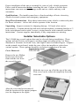
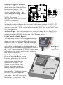
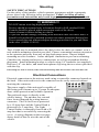
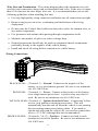
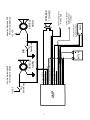
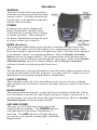
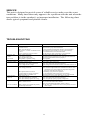
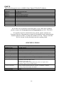
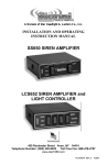
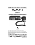
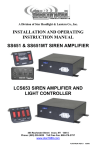
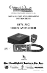
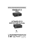
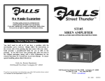
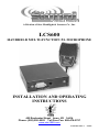
A Division of Star Headlight & Lantern Co., Inc.
LCS600
HANDHELD MULTI-FUNCTION PA MICROPHONE
INSTALLATION AND OPERATING
INSTRUCTIONS
455 Rochester Street Avon, NY 14414
Phone: (585) 226-9025 Toll Free Fax: 888-478-2797
www.star1889.com
PLITSTR53 REV. C
4/22/05
INSTALLATION INFORMATION
MODEL:
SERIAL NO:
PURCHASE DATE:
LCS600
OPTIONS
DEALER:
POS
INSTALLATION DATE:
Radio Repeat
Aux Switching
INSTALLER:
Standard
or
NEG
Relay Control
Air Horn Sound
ALT
Model and serial number located on bottom of unit
TABLE OF CONTENTS
GENERAL DESCRIPTION
INSTALLATION
SAFETY PRECAUTIONS
UNPACKING
INSTALLER-SELECTABLE OPTIONS
MOUNTING
ELECTRICAL CONNECTIONS
WIRING DIAGRAM
OPERATION
GENERAL
POWER
SELECTOR SWITCH
HORN
PA
LIGHT CONTROL
RADIO REPEAT
LED INDICATORS
SERVICE
TROUBLESHOOTING
PARTS
RETURN
SPECIFICATIONS
LIMITED WARRANTY
1
2-7
2
2
2-3
4
4-7
7
8
8
8
8
8
8
8
8
8
9-11
9
10
10
10
11
NOTICE
Due to continuous product improvements, we must reserve the right to change any specifications and information, contained in this manual
at any time without notice. Signal Vehicle Products, Inc. makes no warranty of any kind with regard to this manual, including, but not
limited to, the implied warranties of merchantability and fitness for a particular purpose. Signal Vehicle Products, Inc. shall not be liable for
errors contained herein or for incidental or consequential damages in connection with the furnishing, performance, or use of this manual.
GENERAL DESCRIPTION
The LCS600 microphone control head features Public Address function, Air Horn
tone, and either Radio Repeat function or a 20 Amp Light Control relay. Also
included are LED indicators for Power and Auxiliary function (Light Control or
Radio Repeat function). The remote mount amplifier powers one 100 Watt siren
speaker and includes the Light Control relay wiring and a remote Air Horn tone
input with positive and negative switching options.
-1-
Proper installation of the unit is essential for years of safe, reliable operation.
Please read all instruction before installing the unit. Failure to follow these
instructions can cause serious damage to the unit or vehicle and may void
warranties.
Qualifications - The installer must have a firm knowledge of basic electricity,
vehicle electrical systems and emergency equipment.
Keep These Instructions - Keep these instructions in the vehicle or other safe place
for future reference. Advise the vehicle operator of the location.
Unpacking - Inspect contents for shipping damage. If found, alert carrier
immediately. Contents should include unit with microphone, mounting bracket w/ 2
bolts, microphone bracket with 2 screws, wiring harness with connector and these
instructions. Contact supplier immediately if any components are missing.
Installer Selectable Options
The LCS600 has several options that can be selected during installation. These
options include Positive or Negative auxiliary input activation of the Air Horn,
Standard or Alternate Air Horn Tone, and Light Control or Radio Repeat. Jumpers
on the printed circuit board, inside the case, allow the installer to select these
various options. These options should be set before installation of the unit.
Cover Removal –
Remove the two Philips
head screws from the
front and the two from
the rear of the unit.
Slide the top cover up off of the top of the unit.
This cover can be removed completely from the
siren unit.
After the cover has been removed,
find the location of the option jumpers
(see the diagram to the right).
-2-
Positive or Negative Air Horn
Activation – The green wire
allows activation of the Air Horn
by an external source. This
input is usually wired into the
vehicle horn ring switch. The
wiring diagram on page 7 shows
two connection examples.
NOTE: Permanent
disconnection of the vehicle horn
is NOT recommended.
JUMPERS
AUX
OPTIONS
The unit is factory shipped with the horn option (AUX) defaulted to activation by
applying a positive voltage to the wire (your vehicle horn switches +12VDC). To
activate the Air Horn by connecting to ground or negative (your horn is Ground-side
switched), move the "AUX" option jumper from the "POS" pins to the "NEG" pins.
(See diagram above).
Air Horn Tone – This unit comes with the option to change the Air Horn Tone to
an alternate “flatter” tone. If you wish to change the tone, remove the “TONE”
jumper from the OPTIONS jumper pins. (See diagram above).
Light Control or Radio Repeat –
This unit has a button on the microphone that can
be used to activate your warning lights (up to 20
amps) or it can be used to broadcast the two-way
radio over your P.A. speaker. The unit is shipped
with the defaulted option being Light Control. If
you wish to use the button on your microphone to
instead activate the Radio Repeat Function, remove
the “RAD” jumper from the OPTIONS jumper pins
and connect your radio’s speaker wires to the two
blue wires from this unit.
Radio Repeat Volume Control –
If you are using the Radio Repeat
Function, please note the location
of the volume control
potentiometer inside the case
(pictured to the right). The
volume level is pre-set at the
factory, but it may need to be
initially adjusted with a small
screwdriver after the siren has
been installed. The Radio Repeat
level will vary based upon the
input levels of the signal from
your radio. Once this is set upon
installation, in most cases it will
not need further adjustments.
-3-
Mounting
SAFETY PRECAUTIONS
For the safety of the installer, vehicle operator, passengers and the community
please observe the following safety precautions. Failure to follow all safety
precautions and instructions may result in property damage, injury or death.
!!! WARNING !!!
DO NOT mount in air bag deployment area.
Devices should be mounted only in locations listed in SAE standard J1849.
Controls should be placed within convenient reach of the driver.
Assure clearances before drilling in vehicle.
To prevent internal damage, mounting bolts must not enter case more than 1/4".
Sound levels produced by attached speakers can cause permanent hearing loss.
Never operate this unit without adequate hearing protection for you and others
in the area. (OSHA 1910.95)
The LCS600 may be mounted above the dash, below the dash, on a tunnel, or in a
rack with the mounting u-bracket provided. Choose a mounting location convenient
to the operator and away from any air bag deployment areas. Inspect behind
mounting area for clearance. Assure adequate ventilation to prevent overheating.
Consider wire routing and access to connections, as well as microphone bracket
placement. Install mounting bracket to vehicle using 1/4" hardware (not supplied).
Drill two 1/8" size holes, and install microphone clip using the two screws provided
with the clip.
If mounting in a rack or console, make sure that mounting bolts do not enter case more than 1/4".
Electrical Connections
Electrical connections to the unit are made using a removable connector located on
the back. If the unit needs service the connector can be easily removed without
unwiring the connector.
The power supply of the unit must be capable of
delivering peak currents up to 35 amps for adequate
short circuit protection and reliable operation.
The preferred source is directly at the
vehicle battery. The unit has two external
fuses located beneath the wiring harness
connector. The PA/Air Horn is protected
by a 15-Amp fuse and the Control Head is
protected by a 2 amp fuse. The Light
Control feature is internally fused with a 20
amp fuse that is accessible by removing the
cover. A wiring diagram on the next page
shows detail of how to wire the unit to the
vehicle.
-4-
Wire Size and Termination - The wiring diagram shows the minimum wire size
used for each connection, along with recommended lead color. If the wire is longer
than 10 ft. then use the next larger wire size. It is recommended that you use the
following guidelines when installing this unit:
• Use only high quality crimp connectors and make sure all connections are tight.
• Route wiring to prevent wear, overheating and interference with air bag
deployment.
• Do not route the Control Head cable near the police radio, the antenna wire, or
any strobe components.
• Use grommets and sealant when passing through compartment walls.
• Minimize the number of splices to reduce voltage drop.
• Ground connections should only be made to substantial chassis components,
preferably directly to the negative of the vehicle battery.
• Install and check all wiring before connection to vehicle battery.
Wiring Connections:
3 2 1
6 5 4
9 8 7
12 11 10
BLACK LEAD: (Terminal 2) – Ground: Connect to the negative of the
battery, or to a good chassis ground. Be sure to use minimum
size #14 AWG wire.
RED LEAD: (Terminal 1) – Power: Connect to the positive of the battery,
or to a high current power buss. A power relay may also be
used. Be sure to use minimum size #14 AWG wire.
YELLOW LEAD: (Terminal 4) – Ignition Switched Power: Connect the Yellow
wire to your ignition switched power source. This will
automatically turn the unit off when the vehicle is not running,
thus preventing unnecessary battery drain. If you need to
operate this unit with the vehicle off, you need to connect this
wire to +12 VDC (although this not recommended).
BROWN LEADS: (Terminals 7 & 12) – Speakers: Connect one lead to each
terminal or lead of the speaker. Be sure to use minimum size
#14 AWG wire.
-5-
Optional Wiring Connections:
ORANGE LEAD: (Terminal 9) – Light Control Power Input: If you will be
using the Light Control feature (instead off the Radio Repeat)
connect the Orange lead to the positive of the battery, or to a
high current power buss capable of supplying up to 20 amps of
power. Be sure to use minimum size #14 AWG wire.
Please Note: If you wish to use this feature you must leave the
“RAD” option jumper in place. (Refer to
Installer Selectable Options section for jumper
details.)
WHITE w/ORANGE STRIPE: (Terminal 8) – Light Control Power Output: If
you will be using the Light Control feature (instead off the
Radio Repeat) connect the White w/Orange stripe wire to the
light(s) you wish to control (up to 20 amps). Be sure to use
minimum size #14 AWG wire.
Please Note: If you wish to use this feature you must leave the
“RAD” option jumper in place. (Refer to
Installer Selectable Options section for jumper
details.)
BLUE LEADS: (Terminals 3 & 6) – Radio: Used for radio repeat. Connect
one blue lead to each terminal of the radio speaker or output
connector of the radio. Most radio outputs are isolated, in
which case polarity would not be important. Radios with
polarity sensitive outputs should be connected w/ the blue wire
from pin 6 to the positive radio output, and the blue wire from
pin 3 to the negative radio output. Use #18 AWG wire.
Please Note: If you wish to use this feature you must remove
the “RAD” option jumper. (Refer to Installer
Selectable Options section for jumper details.)
GREEN LEAD: (Terminal 10) - Used for remote Air Horn control. Connect to
the horn ring circuit or a remote switch. Circuit may be
positive or negative with proper jumper selection. (Refer to
Installer Selectable Options section for jumper details.)
NOTE: Cut lead short if not used & insulate w/ electrical
tape.
Testing - Test all of the functions after installation to assure proper operation. Test
vehicle operation to assure no damage to vehicle.
-6-
-7-
AMP
VEHICLE
HORN
5 - No Connection
4 - Yellow (#18 AWG)
3 - Blue (#18 AWG) <Optional>
2 - Black (#14 AWG)
1 - Red (#14 AWG)
Horn
Switch/Relay
OR
BATTERY
+
11 - No Connection
10 - Green (#18 AWG)
9 - Orange (#14 AWG) <Optional>
8 - White w/Orange Stripe (#14 AWG) <Optional>
7 - Brown (#14 AWG)
6 - Blue (#18 AWG) <Optional>
12 - Brown (#14 AWG)
Horn
Switch/Relay
+12 VDC
Positive Switching AUX
Horn Jumper Selected
Connect to Ignition
Switched Power
(+12 VDC)
Connect to Optional
Warning Light
+
RADIO
Connect the Blue wires to
the terminals of speaker or
to the output jack of radio
+
SPEAKER
11 OHMS
VEHICLE
HORN
Negative Switching AUX
Horn Jumper Selected
+12 VDC
Operation
GENERAL
This unit is designed for easy operation
under the stress associated with operating
a motor vehicle. All of the functions are
located right on the hand-held controller
and are easily accessible.
POWER
In order for the unit to function, the
Rotary Thumbwheel On/Off/Volume
switch must be in turned ON by rotating
it counter-clockwise. When turned on,
the Rotary Thumbwheel can also be used
to set the volume level of the PA.
HORN (Air Horn)
This momentary push-button switch provides a simulated air-horn tone while
pressed. This can be used to either replace, or to supplement the normal vehicle
horn and is useful at intersections or in high noise areas. This tone can be changed
to an alternate “flatter” tone during installation. (Refer to Installer Selectable
Options section for jumper details). The activation of the Air Horn may also be
triggered by your Horn Ring switch through the Green wire. (Refer to the Installer
Selectable Options section for jumper settings and the Wiring Connections
sections for details on hooking up the Green wire.)
PA
The attached noise-canceling microphone is used for public address operation when
its push-to-talk button on the side is pressed. You can set the PA volume to a level
appropriate to the situation using the Rotary Thumbwheel.
LIGHT CONTROL
The red button on the side of the microphone can be used to activate a warning
light. Simply press the button to activate your light, and press it again to deactivate
the light.
RADIO REPEAT
This optional function amplifies a radio input for re-broadcast outside the vehicle.
Press the button to activate the radio Repeat, and press it again to deactivate it. To
use this feature, you must de-activate the Light Control feature. (Refer to Installer
Selectable Options section for jumper details).
LED INDICATORS
There-are two LED indicators on the front of the
control head (microphone). The POWER indicator
will light whenever the Rotary Thumbwheel is
turned on. The AUX indicator will light whenever
you activate your external warning light or the Radio
Repeat feature.
-8-
SERVICE
This unit is designed to provide years of reliable service under even the worst
conditions. Many times there may appear to be a problem with the unit when the
true problem is in the speaker(s) or improper installation. The following chart
shows typical symptoms and possible causes.
TROUBLESHOOTING
Symptom
Possible Cause
No power
Power switch not turned on
Connector loose
Siren 15A fuse blown
Do not have +12VDC on Red & Yellow
wires
Loose connection at power source
High voltage protection
No tone - PA
Low voltage protection
works
Microphone button stuck
Bad speaker or speaker wiring
No sound
No PA
PA volume not set properly
Distorted sound
Speaker assembly loose
Intermittent Aux. Input connection
Low or high vehicle voltage
Intermittent sound High voltage protection
Low voltage protection
Horn function
stuck on
Microphone button activation
Circuit breaker in supply connection
Shorted speaker or speaker wire
Horn switch stuck
Aux. Input improperly connected
Aux. Input Polarity Option set wrong
No Radio
Unit not connected to radio
Radio volume too low
No or Low Radio
Radio outputs not isolated and polarity
hooked up backwards
Check
Turn Thumb Wheel
Do you hear a "pop" when turned on?
Is power hooked up backwards? Positive ground vehicle?
Do mounting bolts protrude too far into siren housing?
Is an external fuse or circuit breaker used?
Are the negative leads connected to a good ground?
The input voltage must be less than 16 volts.
The input must be greater than 10V with the siren turned on.
Does microphone button release properly?
Check speaker
Have you tried turning the PA volume control?
Is the speaker bell or tip loose?
Is the Aux. Input used and wired properly?
Input voltage must be between 10 & 16 volts while siren is on.
Is the vehicle voltage regulator working properly?
Is the connector tight on the back of the unit? Is there a loose
connection on a power lead? The input must be greater
than 10V with the siren turned on.
Is something lying on the microphone?
Is a circuit breaker used with at least a 30A rating?
Does the speaker have water damage, or is a wire pinched?
Does the horn switch return fully when released?
Is the Aux. Input used and wired properly?
Is the AUX jumper option properly configured?
Is the radio connected properly to the unit?
Can you hear the radio in the vehicle?
Have you tried turning the Radio volume control?
Are the radio wires connected to the correct polarity from the
radio output?
-9-
PARTS
The following parts are available from Signal Vehicle Products:
Part
Description
S30235-17P
Siren Top Cover
P30234-17P
Siren Bottom Mounting Plate
SWH-75
Wiring Harness
P30069-38
Microphone Bracket with Screws
P30056-16
1/4-20 x 3/8" Hex Locking Bolt
P30028-6
15 Amp Automotive Fuse
P30028-16
2 Amp Automotive Fuse
P30028-1
20 Amp Automotive Fuse
LCS600-CH
Noise Canceling Microphone and Hand Held Control Head
P30147-44P
Mounting Bracket
P30052-30
Case Screws
If you have any questions concerning this or any other SVP product,
please contact our Customer Service Department at (585) 226-9025.
If a product must be returned for any reason, please contact our
Customer Service Department to obtain a Returned Goods Authorization
number (RGA#) before you ship the product to SVP. Please write the
RGA# clearly on the package near the mailing label.
SPECIFICATIONS
Input Voltage
Input Current
Standby Current
Audio Frequency
Audio Output
Output Power
10 - 16 VDC (negative ground)
8.0 Amps @ 13.6 VDC (100W speaker)
Less than 150 mA
200Hz - 10 kHz + 3db
40 watts @13.6 VDC (100W speaker)
105 WATTS RMS MAX. @ 15.0 VDC (100W speaker)
Air Horn Frequency
High Voltage Protection
Short Circuit Current
Operating Temperature
Controls
675Hz - 1633Hz (variable)
16 - 18 VDC will cause siren output to cease, resumes at normal voltage
30 AMPS (supply circuit must be capable of supplying this)
-15° F to +140°F
Rotary Thumb Wheel - On/Off/Volume
Momentary push-button Horn switch
Momentary push-button PA
Auxiliary input (jumper programmable) for positive or negative horn
Pushbutton Light Control or Radio Repeat
Detachable, 12-pin, positive locking connector with pigtail leads.
Positive, Ignition Switched Positive, Negative, (2) Speaker, (2) Radio,
Auxiliary, Light Control Input and Output
6" Wide, 6-1/2" Deep, 2" High
2.2 lbs.
Connections
(12-Pin Connector)
Size
Shipping Weight
-10-
LIMITED WARRANTY
Signal Vehicle Products warrants this new product to be free from defects in
material and workmanship, under normal use and service, for a period of one (1)
year from the date of delivery to the first user-purchaser.
During this warranty period the obligation of Signal Vehicle Products is limited to
repairing or replacing, as Signal Vehicle Products may elect, any part or parts of
such product which after examination by Signal Vehicle Products is determined to
be defective in material and/or workmanship.
This warranty does not cover labor charges for removal or re-installation of the
product. Fuses and lamps are not covered under this warranty.
This warranty does not extend to any unit that has been subjected to abuse, misuse,
improper installation or which has not been adequately maintained, nor to units
which have problems related to service or modification at any facility other than the
manufacturer.
THERE ARE NO OTHER WARRANTIES, EXPRESSED OR IMPLIED,
INCLUDING BUT NOT LIMITED TO, ANY IMPLIED WARRANTIES OF
MERCHANTABILITY OR FITNESS FOR A PARTICULAR PURPOSE. IN NO
EVENT SHALL SIGNAL VEHICLE PRODUCTS BE LIABLE FOR ANY LOSS OF
PROFITS OR ANY INDIRECT OR CONSEQUENTIAL DAMAGES ARISING OUT
OF ANY SUCH DEFECT IN MATERIALS OR WORKMANSHIP.
A Division of Star Headlight & Lantern Co., Inc.
455 Rochester Street Avon, NY 14414
Phone: (585) 226-9025 Toll Free Fax: 888-478-2797
www.star1889.com
-11-