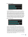
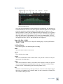
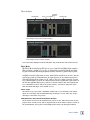
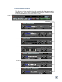
1
™
USER’S GUIDE
Pro Audio Lab
™
Precision Audio Analysis and Sound
Generation Laboratory
Plug-in for Mackie Digital Mixers
Read This First: Mackie Designs Plug-in Software License
Please read this license carefully before using the accompanying Software. By downloading and using the
Software, you are agreeing to be bound by the terms of this license. Software as used herein means all computer
code (both source and object) including, but not limited to, all interfaces, navigational devices, search engines,
databases, menus, menu structures or arrangements, drivers, development tools, icons, operational instructions,
scripts, commands, and syntax, whether created, or licensed from third parties by Mackie Designs, including all
associated documentation.
1. Software License. Any Software whether on disk, in read-only memory, or on any other media, and related
documents are licensed to you by Mackie Designs. You own the disk(s) on which the Software is recorded but
Mackie Designs and/or Mackie Designs’ Licensor(s) retain all rights, title, and interest to the Software and related documentation. This License allows you to use the Software on a single computer and make one copy of the
Software in machine-readable form for backup purposes only. You must reproduce on such copy Mackie Designs’
copyright notice and any other proprietary legend on the original copy of the Software.
2. Restrictions on Software Use. The Software contains copyrighted material, trade secrets and other proprietary material and in order to protect them you may not decompile, reverse engineer, disassemble or otherwise
reduce the Software to human-perceivable form, or in any way analyze or utilize in a manner inconsistent with
this license, or allow a third party to do so. You may not modify, network, rent, lease, loan, distribute, create
derivative works, or use the Software to create a compilation based upon the Software in whole or in part. You
may not electronically transmit the Software from one computer to another over a network or other means of
transmission.
3. Support. You acknowledge and agree that Mackie Designs may not offer any technical support in the use of
the Software.
4. Termination. This License is effective until terminated. You may terminate this License at any time by destroying the Software and related documentation and all copies thereof. This License will terminate immediately
without notice from Mackie Designs if you fail to comply with any provisions of this License. Upon termination
you must destroy the Software and related documentation and all copies thereof.
5. Export Law Assurances. You agree and certify that neither the Software nor any other technical data received from Mackie Designs, nor the direct product thereof, will be exported outside the United States except as
authorized and as permitted by the laws and regulations of the United States and with Mackie Designs’ express
permission.
6. Government End Users. If you are acquiring the Software on behalf of any unit or agency of the United States
Government, the following provisions apply. The Government agrees:
(i) if the Software is supplied to the Department of Defense (DOD), the Software is classified as “Commercial
Computer Software” and the Government is acquiring only “restricted rights” in the Software and its documentation as that term is defined in Clause 252.227-701(c)(1) of the DFARS; and
(ii) if the Software is supplied to any unit or agency of the United States Government other than DOD, the
Government’s rights in the Software and its documentation will be defined in Clause 52.227-19(c)(2) of the FAR
or, in the case of NASA, in clause 18-52.227-86(d) of the NASA supplement to the FAR.
7. Limited Warranty on Software Media (if provided on disks). Mackie Designs warrants the disks on which
the Software is recorded to be free from defects in materials and workmanship under normal use for a period of
ninety (90) days from the date of purchase as evidenced by a copy of the purchase receipt. Mackie Designs’ entire liability and your exclusive remedy will be the replacement of the defective disk when it is returned postage
prepaid to Mackie Designs at the address below or a Mackie Designs’ authorized representative with a copy of
the purchase receipt. Mackie Designs will have no responsibility to replace a disk damaged by accident, abuse or
misapplication. THIS WARRANTY SPECIFICALLY EXCLUDES ANY OTHER WARRANTY RELATED TO SOFTWARE MEDIA, INCLUDING, BUT NOT LIMITED TO, ANY IMPLIED WARRANTIES ON THE DISKS, SUCH
AS THE IMPLIED WARRANTIES OF MERCHANTABILITY OR FITNESS FOR A PARTICULAR PURPOSE OR
USE. THIS WARRANTY GIVES YOU SPECIFIC LEGAL RIGHTS, AND YOU MAY ALSO HAVE OTHER RIGHTS,
WHICH VARY FROM STATE TO STATE AND FROM COUNTRY TO COUNTRY.
User’s Guide
8. Disclaimer of Warranty on Software. You expressly acknowledge and agree that use of the Software is at
your sole risk. The Software and related documentation are provided “AS IS” and without warranty of any kind.
MACKIE DESIGNS EXPRESSLY DISCLAIMS ALL WARRANTIES, EXPRESS OR IMPLIED, INCLUDING, BUT
NOT LIMITED TO, THE IMPLIED WARRANTIES OF MERCHANTABILITY AND FITNESS FOR A PARTICULAR
PURPOSE OR USE. MACKIE DESIGNS DOES NOT WARRANT THAT THE FUNCTIONS CONTAINED IN THE
SOFTWARE WILL MEET YOUR REQUIREMENTS, OR THAT THE OPERATION OF THE SOFTWARE WILL
BE UNINTERRUPTED OR ERROR-FREE, OR THAT DEFECTS IN THE SOFTWARE WILL BE CORRECTED.
FURTHERMORE, MACKIE DESIGNS DOES NOT WARRANT OR MAKE ANY REPRESENTATIONS REGARDING
THE USE OR THE RESULTS OF THE USE OF THE SOFTWARE OR RELATED DOCUMENTATION IN TERMS
OF THEIR CORRECTNESS, ACCURACY, RELIABILITY, OR OTHERWISE. NO ORAL OR WRITTEN INFORMATION OR ADVICE GIVEN BY MACKIE DESIGNS OR A MACKIE DESIGNS AUTHORIZED REPRESENTATIVE
SHALL CREATE A WARRANTY OR IN ANY WAY INCREASE THE SCOPE OF THIS WARRANTY. SHOULD THE
SOFTWARE PROVE DEFECTIVE, YOU (AND NOT MACKIE DESIGNS OR ANY MACKIE DESIGNS AUTHORIZED REPRESENTATIVE) ASSUME THE ENTIRE COST OF ALL NECESSARY SERVICING, REPAIR OR CORRECTION. SOME STATES DO NOT ALLOW THE EXCLUSION OF IMPLIED WARRANTIES, SO THE ABOVE
EXCLUSION MAY NOT APPLY TO YOU.
9. Limitation of Liability. UNDER NO CIRCUMSTANCES INCLUDING NEGLIGENCE, SHALL MACKIE DESIGNS BE LIABLE FOR ANY INCIDENTAL, SPECIAL OR CONSEQUENTIAL DAMAGES INCLUDING, BUT NOT
LIMITED TO, LOST PROFITS OR EARNINGS, DAMAGE TO PROPERTY OR PERSON, OR ATTORNEYS’ FEES
THAT RESULT FROM THE USE OR INABILITY TO USE THE SOFTWARE OR RELATED DOCUMENTATION,
EVEN IF MACKIE DESIGNS OR A MACKIE DESIGNS AUTHORIZED REPRESENTATIVE HAS BEEN ADVISED
OF THE POSSIBILITY OF SUCH DAMAGES. SOME STATES DO NOT ALLOW THE LIMITATION OR EXCLUSION OF LIABILITY FOR INCIDENTAL OR CONSEQUENTIAL DAMAGES SO THE ABOVE LIMITATION OR
EXCLUSION MAY NOT APPLY TO YOU. IN NO EVENT SHALL MACKIE DESIGNS’ TOTAL LIABILITY TO YOU
FOR ALL DAMAGES, LOSSES, AND CAUSES OF ACTION (WHETHER IN CONTACT, TORT (INCLUDING NEGLIGENCE) OR OTHERWISE) EXCEED THE AMOUNT PAID BY YOU FOR THE SOFTWARE.
10. Controlling Law and Severability. This License shall be governed by and construed in accordance with the
laws of the United States and the State of Washington, as applied to agreements entered into and to be performed
entirely within Washington between Washington residents. If for any reason a court of competent jurisdiction
finds any provision of this License, or portion thereof, to be unenforceable, that provision of the License shall be
enforced to the maximum extent permissible so as to effect the intent of the parties, and the remainder of the
License shall continue in full force and effect.
11. Complete Agreement. This License constitutes the entire agreement between the parties with respect to the
use of the Software and related documentation, and supersedes all prior or contemporaneous understandings or
agreements, written or oral, regarding such subject matter. No amendment to or modification of this License will
be binding unless in writing and signed by a duly authorized representative of Mackie Designs.
Mackie Designs Inc. • 16220 Wood-Red Road NE • Woodinville, WA 98072 • USA
©2003 Mackie Designs Inc.
All Rights Reserved.
User’s Guide
Iconography
This icon identifies a description of how to perform an action with the mouse.
This icon will lead you to some further explanations of features and practical tips.
OCEAN
LINER
This icon marks information that is very important, so please make sure you have a
read.
This icon does not appear in this guide.
Note: Any future revisions of this guide will be available for viewing and downloading
from: www.mackie.com
“Mackie” and the “Running Man” figure are trademarks or registered trademarks of
Mackie Designs Inc. All other brand names mentioned are trademarks or registered
trademarks of their respective holders, and are hereby acknowledged.
Part No. SW0062 Rev. A 03/2003
© 2003 Mackie Designs Inc. All Rights Reserved.
User’s Guide
Contents
Mackie Designs Plug-in Software License --------------------- 2
Introduction ---------------------------------------------------------6
About Acuma Labs ----------------------------------------------------------6
About the D8B UFX Card---------------------------------------------------6
About Pro Audio Lab -------------------------------------------------------7
Requirements ----------------------------------------------------------------7
Obtaining the Plug-In ------------------------------------------------------7
Unlock Procedure -----------------------------------------------------------8
Using Pro Audio Lab------------------------------------------------9
The Status Screen ------------------------------------------------9
The Analysis Screens -------------------------------------------10
The Levels Screen ------------------------------------------------------- 11
Spectrum Analyzer -----------------------------------------------------16
Phase Analyzer --------------------------------------------------------- 18
The Generation Screens----------------------------------------19
Noise Generator-------------------------------------------------------- 20
Slate Tone Generator --------------------------------------------------21
The Oscillator ---------------------------------------------------------- 22
The Piano Tuning Reference ----------------------------------------- 23
The Guitar Tuning Reference ---------------------------------------- 24
The Bass Tuning Reference------------------------------------------- 25
The A440 Tuning Reference ----------------------------------------- 26
Plug-In Configuration and Routing --------------------------- 27
Configuring the Plug-In ----------------------------------------------- 27
Automation and Snapshot Control ---------------------------- 31
FX Routing ----------------------------------------------------------32
User’s Guide
Introduction
Thank you for purchasing Acuma Labs’ Pro Audio Lab. This is a precision audio
analysis tool and sound generation software plug-in for the Mackie D8B digital mixer. It offers a broad cross section of sophisticated meters, noise generation devices,
and highly accurate instrument tuning references. Pro Audio Lab presents finely
calibrated stereo and mono level metering that simultaneously displays Clip, Peak
Level, RMS, VU, Loudness Peak and VU, Sum and Difference VU, Correlation, and
Loudness Balance meters. The stereo X/Y Phase Meter, Phase Scope, and selectable (10 to 61-band) Spectrum Analyzer are portrayed by simplified and easy-to-read
display graphs that let you view and analyze your signal for concise and up-to-date
information. The built-in tone generators feature a professional oscillator with selectable waveforms, a Pink and White noise generator, and Slate tone generation
with editable frequencies and burst times. Last but not least, Pro Audio Lab provides
you with “dead-on” tuning references (down to semi-tones and cents) for guitar, bass,
and piano with presets that include alternate tuning presets such as “open G, C,
Dobro, capo, and 5 string bass.”
About Acuma Labs
Acuma Labs develops real-time embedded systems for professional audio applications to create high-quality products for the music and pro-audio industries. Acuma
specializes in digital audio effects using DSP, real-time operating systems, graphical
user interfaces, and digital hardware design.
About the D8B UFX Card
The Mackie UFX card provides robust processing power for computation-heavy
plug-ins. The UFX card is a 4-in/4-out architecture, which means it can support four
mono, two mono and one stereo, or two stereo sends simultaneously. Up to four UFX
cards can be installed in the D8B, allowing up to sixteen simultaneous single-channel
effects, eight stereo plug-ins, or combinations thereof.
User’s Guide
About Pro Audio Lab
Status Screen
Levels Screen
(from the Analysis
drop-down menu)
Oscillator Screen
(from the Generator
drop-down menu)
Main Screen (with Levels and Oscillator open)
The main screen is an overview of the primary analysis meters and tone generation
graphs. Each “top level” meter can be selected and enlarged using your mouse to
“zoom in” for an easy-to-read view of the selected data. Two fundamental categories,
Analysis and Generation, are located at the top of the screen and each has a pulldown menu for choosing individual functions. One screen from each can be open
at the same time, for example, figure 1 shows the Levels display from the Analysis
drop-down menu, and the Oscillator from the Generation menu.
As with all Mackie plug-ins, Pro Audio Lab can be routed as an “insert” or “auxiliary” connection. Typically, it is recommended that Pro Audio Lab be routed as an
auxiliary when monitoring inputs. This also allows monitoring of tone generation via
the effects return bank. Inserting is primarily used on the Master Outputs for concise
control during mixdown. The tone generator audio returns to the D8B Effects Bank
channels that correspond to the card slot number that Pro Audio Lab uses in the
Plug-in Configuration Window.
Requirements
• One or more Mackie UFX cards
• Mackie Real Time OS 3.0 or greater Software
• Plug-in Software
We will assume you have successfully installed a Mackie UFX card and Mackie Real
Time OS 3.0 software or greater. If you have encountered problems with the installation of hardware or software, please see their associated user guides or contact
Mackie support (www.mackie.com).
Obtaining the Plug-In
The plug-in is available from our website: www.mackie.com. Carefully follow the instructions on the website, download the plug-in, and load it onto your D8B.
User’s Guide
Unlock Procedure
1. Locate your D8B’s Electronic Serial Number (ESN). This is displayed at the
bottom of the Licensing window, which is accessed from the Setup screen.
The 12-digit ESN is made from numbers 0–9 and letters A–F. It is unique to
the D8B processor, and is not the same as the serial number on the rear of
the control surface or CPU chassis.
D8B SETUP screen’s
LICENSING window
LICENSING
AUTHORIZE
D8B Electronic
Serial Number (ESN)
An Unlocked
Plug-in
2. You will also need your plug-in’s serial number.
3. To obtain the unlock code, have the ESN and plug-in serial number ready.
Then you have two options:
• Log on to the Mackie plug-in authorization web page:
http://www.mackie.com/D8Bauthorize.htm
or
• Telephone Mackie Tech Support at 800-258-6883.
4. When you have obtained an unlock code, open the D8B Setup window, and
click Licensing.
5. With your plug-in highlighted in the Licensing window, click Authorize, and
enter your unlock code in the UNLOCK CODE box. Click Enter, and enjoy
your newly expanded console.
User’s Guide
Using Pro Audio Lab
The Status Screen
Factory/User Presets
Mem A/B
Write
Input Select
Menu
Analysis
Enable Min/Close
Generation
Factory/User Presets
Toggle the up/down arrows to select Factory Presets, or create your own and save
them to User Presets.
Input Select
Select stereo inputs from any of the DB8’s pre, post, or auxiliary channels.
Enable
This switches Pro Audio Lab from the inactive state to active.
Minimize/Close Button
These buttons minimize Pro Audio Lab to a simplified version for better viewing of
the D8B screen. To switch from one screen to another, simply toggle between the
buttons to expand and shrink. Selecting X will hide Pro Audio Lab.
Mem A/Mem B
Memory A and Memory B are two separate storage banks that let you temporarily
store your set-ups. This is handy for quick A/B comparison and referencing.
Write Button:
Write enables the D8B’s automation so that all of the changes that you make to the
Pro Audio plug-in will be recorded as part of the D8B session. This works in a manner similar to a channel’s write button. To record automation for a plug-in, “All” must
be turned on in the automation section of the D8B (and automation must be out of
Bypass). When the D8B is recording, plug-in parameter edits are recorded only if the
plug-ins Write button is ON, or if Auto Touch (in the automation section) is turned
on. When you hit stop, the plug-in's Write button turns OFF.
Menu Button:
This drop-down menu enables familiar functions such as undo, redo, load, save, reset, cut, copy and paste. Saving as “User Preset” saves all parameters of Pro Audio
Lab, including customized settings in the Analysis and Generation menus.
Analysis:
The Analysis button opens a drop-down menu that lets you select from Levels,
Spectrum Analyzer, or Phase Analyzer. This is where specific analysis tools can be
selected and profiled.
Generation:
The Generation button opens a drop-down menu that lets you select from a variety of
sound generation devices such as Noise, Slate Tones, Oscillator, and the Tuning references: Piano, Guitar, Bass, and A440.
User’s Guide
The Analysis Screens
The Levels, Spectrum Analysis, and Phase Analysis options are selected from the
Analysis drop-down menu found in the Status Screen. Only one option can be open at
a time. The Levels menu is further expandable by clicking on any of the level meters.
See Page 9
Analysis
See Page 11
Each Meter is
expandable by
clicking
See Page 16
See Page 18
User’s Guide
The Levels Screen
Peak
The Levels Screen
RMS
VU
Sum/Diff
Loudness Balance
Correlation
Loudness
Select the Levels Screen from the Analysis drop-down menu. This shows an overview
grouping of the primary meters of the Analysis section. Each meter can be isolated
and expanded for a detailed view of the selected audio measurement, by selecting a
meter and double-clicking on the display. The expanded meters can be minimized by
clicking again. The individual meters are explained in more detail below:
Peak Level
Peak Level (expanded view)
Peak Level presents a fast-responding peak level with slow decay. Additionally, an
Overload LED can detect digital clip. As digital distortion is very unforgiving, this
meter is useful in maintaining an optimum peak level from your input signal or as
a highly visible guide inserted on the master outputs. Obviously it’s crucial to avoid
digital clipping, but it’s also important to maintain enough level to sample in the best
sounding range of the D8B’s gain structure. The range is –96 dB to 0 dB.
Peak Level Meters, sometimes called PPM (Peak Program Meters) respond to within
1 dB of the actual peak level within 10 ms, and within 4 dB in 3 ms, to capture very
fast transients that are ignored by the slow response of an averaging VU or RMS meter. Peak Level does not demonstrate the loudness of your program. The difference
between Peak and VU meters can be as much as 12 dB or 4x the apparent volume.
Many engineers therefore combine the best of both worlds by using both Peak and
VU metering for the best results. The Overload Clip light responds to a single sample
of digital clip and remains on for two seconds after the last measured clip.
User’s Guide
RMS Level
RMS (expanded view)
Root Mean Square (RMS) is an audio measurement that correlates signal energy
with a reference signal. Neither a peak, nor an average, RMS is derived by squaring
all the instantaneous voltages from a waveform, averaging the squared value, and
then taking the square root of that value. Thus, RMS is a mathematical measurement devised to characterize the level of a given signal. RMS Level is a measurement
that is very helpful in describing the energy of a waveform in RMS values. RMS
levels are similar to average values and do not vary much even when high transient
peaks are presented. The ratio between the Peak and the RMS is called the crest
factor. The meter is calibrated to display 0 dB with a sine wave input at 0 dBFS (Full
Scale). These meters are measured in dB and range from –96 to 0 dB. A square wave
has a crest factor of 1.0. The RMS meter is calibrated for the crest factor of a sine
wave such that a digital peak-to-peak signal (0 dBFS) will report 0 dB.
RMS
Peak to Peak
RMS = Peak / 2 = Peak x 0.0707
Peak = RMS x 2 = RMS x 1.414
Meter Graph : What the Meters Measure
User’s Guide
VU Meter (Volume Unit Meter)
VU Meters (expanded view)
Probably the first audio measurement that many of us learned is the familiar VU
meter that we equate with distortion overload. The VU Meter is actually defined by
a specific set of attributes and response characteristics known as ballistics, which
estimate the loudness of a signal based on the ear’s ability to compress intensity
differences and downplay transient peaks. The VU meter represents a commonly accepted compromise of what our ear does naturally. Pro Audio Lab’s VU meters read
average level but ignore the instantaneous peaks that are the job of the Peak Level
Meters. The VU meters offer an accurate volume measurement that lets you judge
the levels of your program. There is often a 12 dB difference between peak level and
the level indicated by the VU meters. A VU meter is designed to have a relatively
slow response. It is driven from a full-wave averaging circuit defined to reach 99%
full-scale deflection in 300 ms and overshoot not less than 1% and not more than
1.5%. The VU meter is calibrated to display 0 VU for a sine wave at 0 dBFS.
Loudness (A-Weighted Level)
Loudness /A-Weighted Level (expanded view)
Loudness is a measurement that uses filtering from the A-Weighted curve to create the best average representation of what our ear perceives as loud at different
frequencies. The term “A-Weighted” refers to particular plotted curve that ranges
from –45 dB to +3 dB with a frequency range of 20 Hz to 10 kHz. This curve is an
approximate but accepted standard measurement based on averaging statistics from
the equal loudness contour graph. This type of audio measurement is very useful in
determining what volume levels need to be applied to two separate mono channels or
to the left/right of a stereo channel. For example, say you have two matching guitar
parts that have been recorded on separate tracks. Using the Loudness meter, you
can clearly see how the two channels compare and where you need to compensate to
achieve a loudness balance. Another useful application is using the meters on Master
L and R outputs to achieve a desired volume.
User’s Guide
Note: When using this application on the left and right masters, remember to turn off
the enable button in the Pro Audio Lab GUI to disable the Tone Generation, as you
simply need to see the meters. The Loudness Meter displays both a VU and a Peak
Level meter on the same graph.
There is no absolute measurement for how the ear hears frequency response and
consequently hearing can vary greatly from one person to another. Generally, hearing
is much better in the high-midrange and less sensitive toward both extremes. For example, young children can often hear to above 20 kHz while older people often have
difficulty hearing above 5 kHz. It is generally accepted that average resonance in the
eardrum is most sensitive in the 2.5 kHz to 4 kHz regions. The human ear does not
hear frequency response as flat and changes substantially depending on the intensity
of the sound presented.
Very Important: With every 3 dB increase in output, double the amplifier and
speaker power is required. Typically, the upper end of the ear’s intensity threshold is
140 dB SPL. This is where damage to the hearing starts to occur even with limited
exposure. Sounds above this threshold, such as gunshots, jet planes, machines, and
continuous loud monitoring, can be very damaging to the ear.
Sum/Difference
Sum/ Difference (expanded view)
The Sum and Difference meters analyze the sum of two input channels, and the difference between them in dB VU. This meter is useful in determining the association
of two separate channels, or a stereo channel that is creating comb filtering caused
when a stereo pair is summed to mono.
User’s Guide
Correlation/Loudness Balance
Correlation (expanded view)
Correlation
This clear and easy-to-read display is designed to help you understand the complex
phase relationship between two signals, and shows how the signals relate to each
other. The correlation meter measures the similarities between two signals by displaying a range value of –1 (two signals are 180°out of phase) or +1 (indicating that
the signals are perfectly in phase). 0 means that the two signals are not correlated.
For most stereo applications a large positive number is typically 0.5 to 1.0.
Loudness Balance
This shows the A-weighted VU level relationship between two signals. The meter
displays the ratio between these two signals, and plots the ratio from the center
outwards. A value less than 1:1 (such as 1:2) indicates higher loudness on the right
channel. A value greater than 1:1 (such as 2:1) indicates higher loudness on the left
channel.
User’s Guide
Spectrum Analyzer
Range
Left
Right
Mono
Stereo
Freeze
Peak
Reference
Precision
Spectrum Analyzer Screen
Select the Spectrum Analyzer from the Analysis drop-down menu. The graphical representation indicates the level of an audio signal at various frequencies. The analyzer
performs a Fast-Fourier Transform (FFT) on the input audio to convert it to frequency information. This is put into individual bands and displayed as a bar graph. A
spectrum analyzer designed to indicate the level of audio at 31 different frequencies
across the audio range is also known as a 1/3-octave spectrum analyzer. Up to 61
bands (1/6th octave) are supported in mono mode, and up to 31 bands (1/3rd octave)
are supported in stereo. 10, 15, and 20 bands are also supported.
Range (–96 dB to –30 dB)
The analyzer range enables you to adjust the viewing range of your signal between
–96 dB to –30 dB.
Left/Right Buttons
Select either right or left channel inputs for viewing.
Mono
The mono button enables a mono view.
Stereo
Use to select a stereo view.
Freeze
The freeze button will freeze the current frame to let you take a closer look at your
signal in the spectrum graph.
Peak
When the Peak button is enabled, each band’s meter displays its own peak, presented as a small individual yellow hash mark at the top of each meter. When a band's
peak is reached, a hash mark appears and then gradually decay.
Ref
Reference is a hand reference point represented as a red line on the analyzer graph
that can be set anywhere from –60 dB to 0 dB. Use this to maintain a relativity reference that most suits your need.
User’s Guide
Precision
This offers precision viewing ranges from 1 octave to 1/6 octave with additional
views in between. Click on the Precision window to open a drop-down menu to
choose from 1 octave, 2/3 octave, 1/2 octave and 1/6 octave views. The maximum
resolution is 1/6 octave for the mono display, and 1/3 octave for stereo.
Imperfections in the audio signal caused by audio feedback, room equalization problems, errant filter settings, and many other signal problems can be identified more
readily and effectively by looking at the signal with this spectrum analyzer.
Note: The spectrum analyzer display has a rather soothing and mesmorizing effect,
which may trigger sleep and vivid dream sequences in certain pet hamsters and
parakeets. We recommend that any furry animals in your studio are turned away
from the screen, or given some distraction, such as a big wheely thing, or a beak full
of millet, or both.
User’s Guide
Phase Analyzer
Phase Meter
Loudness
Difference
Balance
Sum
Correlation
Phase Scope
Phase Analyzer Screen (Out of Phase example)
Phase Analyzer Screen (In Phase example)
Select the Phase Analyzer from the Analyzer drop-down menu of the Status Screen.
Phase Meter
The Phase Meter displays an X/Y plot of a set of raw Left and Right audio samples.
This results in a ‘swarm of bees’ type of display that is useful in visually determining the correlation and left/right power balance, referred to generically as phase.
A highly correlated signal such as mono will display all the points in a vertical line.
A highly correlated signal such as mono, with a phase inversion on one side, will display all the points in a horizontal line. A signal present on one channel and not the
other will display all the points at a 45° angle to the left or right of vertical, depending on which signal is present. A completely uncorrelated signal with equal levels on
the left and right will display the points in a ‘random’ fashion. All other signals will
be a combination of these, where the power balance, correlation, and phase determine the width and angle of the swarm of bees.
Phase Scope
The Phase Scope represents a summary of what can be seen visually on the Phase
Meter. It is an ellipse that is mathematically calculated to be the same size, shape,
and angle of the Phase Scope data.
Sum/Difference and Correlation/Loudness Balance
Click on these meters for an expanded view. These are the same meters that are displayed on the Levels Screen, but are duplicated here in the Phase section to assist in
the determination of the phase relationships between the left and right channels.
User’s Guide
The Generation Screens
Tone Generator options are selected from the Generation drop-down menu found in
the Status Screen. This is where you will find a wide variety of oscillators and tuners
to suit any task. Only one option can be open at a time.
See Page 9
Generation
See Page 20
See Page 21
See Page 22
See Page 23
See Page 24
See Page 25
See Page 26
User’s Guide
Noise Generator
Burst/Pause Total Time
Ratio
The Noise Generator
Level
White
Repetitions
Pink
Start
This noise generator produces white and pink noise, and has independent burst/
pause ratio, total time, and repetitions. White and pink noise are random signals that
include all of the audio frequencies. The noise simulates the random thermal motion
of electrons. When either white or pink noise is amplified, we perceive the sound as
hiss. White noise has a flat linear frequency response, while pink noise has a flat
logarithmic frequency response (as shown by a logarithmic Spectrum Analyzer).
Level
Use your mouse to select an output level ranging from off to 0 dB RMS of a full-scale
sine wave. The reference level is based on 0 dB RMS output values generated by the
noise generator.
Noise Duration: Burst/Pause Ratio
This ratio refers to the percentage of burst vs. pause that is applied to the generated
noise. This pause interval can be assigned to any increment between 0 seconds (off)
and 100 seconds (full). To adjust the ratio, use your mouse to select the up/down
arrows, or scroll the numbers in the small window, or grab the blue bar graphic and
move it left or right.
Noise Duration: Total Time
This refers to the combined length of the burst and the pause. This increment can be
assigned to any interval between 0 seconds (off) and 60 seconds. Use the mouse to
select the up or down arrows or to scroll the digit.
Repetitions
Repetitions refer to the number of repetitions of the noise bursts. The number of
repetitions can be selected to repeat a sequence over any number of times between 1
and infinity.
Noise Type: White
White noise is unfiltered, unaltered thermal noise just like you hear when you turn
your amplifier all the way up to listen to the noise floor.
Noise Type: Pink
Pink noise is white noise that has been filtered with a pinking filter. This is a 3 dB
per octave low-pass filter, starting at the lowest frequency band. It produces a ‘flat’
spectrum when viewed with a logarithmic spectrum analyzer.
Start
Left-click to start the noise generator, click again to stop. Right-click to play a momentary noise burst for as long as you hold down the button.
User’s Guide
Slate Tone Generator
Burst/Pause Total Time
Ratio
The Slate Tone Generator
Level
Tone Select
Start
The familiar three-step oscillated tone sequences (like we used to hear at the beginning of cassette albums), are known as Slate Tones. They are used to calibrate
faders, buses, and meters between consoles and decks to insure that all input and
output levels are set to a single reference point. Our Slate Tone Generator is designed to give you highly flexible signals to help you optimize routing in your system.
Level
Use your mouse to select an output level ranging from off to 0 dB RMS of a full-scale
sine wave. The reference level is based on 0 dB RMS output values generated by the
noise generator.
Tone Duration
Tone duration refers to the amount of tone vs. pause (no sound). These tones have
adjustable durations that can be customized to suit your needs. Adjust the duration
by grabbing the tone/ pause bar with your mouse.
Burst/Pause Ratio
The Burst/Pause Ratio refers to the percentage of burst compared to pause that is
applied to the generated noise. This pause interval can be assigned to any increment
between 0 seconds (off) and 100 seconds (full). To adjust the ratio, use your mouse
to select the up/down arrows, or scroll the numbers in the small window, or grab the
blue bar graphic and move it left or right.
Total Time (tone sequence)
Total Time refers to the combined length of tone and pause. Pause can be assigned
to any interval between 0 seconds (off) and 60 seconds. Use the mouse to select total
time using the up or down arrows or to scroll the digits.
Tone Select
This lets you choose the frequency of each tone from 16 Hz to 20.0 kHz. Choose
from standard three-tone oscillator sequences that are generally accepted as industry standards, or customize your own. You can enable or disable individual tones by
pressing the IN buttons to bring them in or out of play.
Start
Left-click to start the tone generator, click again to stop. Right-click to play a momentary tone burst for as long as you hold down the button.
User’s Guide
The Oscillator
Waveform
Graphic
Oscillator Screen
Level
Wave Type
Coarse
Fine
Delay
Start
The oscillator has many uses in sound testing, as it can zero in on a specific frequency and generate a constant steady tone. For example, the sine wave, having no
harmonic content, is very useful in determining distortion in a signal that can cause
very apparent changes in tone quality.
Level
Use your mouse to select an output level ranging from off to 0 dB.
Waveform Type
This lets you select the type of waveform to generate as your audio signal. The oscillator can generate Acuma (three harmonics), sine, saw tooth, inverted saw tooth and
three ‘square’ waveforms. The default is a sine wave, but you can select other waveforms using the up and down arrows, or by grabbing the graphic and moving it left or
right.
Course
With a range of 15.6 Hz to 20.2 kHz, the Course control enables you to “ball-park” a
particular frequency range, prior to using the Fine control.
Fine
Once you have selected a Course frequency range, you can use the Fine control to
fine-tune your frequency to an exact setting.
Tip: A good way to approach this is to set your Fine control to its default (control/
click). Use the Course control to hone in on the frequency, and then use the Fine
control to achieve a desired setting. You can save your customized settings using the
Save User Preset in the drop-down menu.
Delay
You can offset your signal, one sample at a time, by adjusting the Oscillator Delay to
add or subtract samples in the right or left channel of your source. Use your mouse
to adjust the Delay knob or use the up/down arrows. This is useful for identifying
phase problems in your source signals. Once you have identified how much adjustment is needed, you can correct the phase by make adjustments using the D8B
Channel Delay.
Tip: Using the Delay feature in Pro Audio Lab does not adjust the delay in your signal.
Remember, it’s for identifying a problem only. Use the Channel Delay feature in the
D8B to make sample changes.
Start
Left-click to start the Oscillator, click again to stop. Right-click to play a momentary
tone burst for as long as you hold down the button.
User’s Guide
The Piano Tuning Reference
Level
Note Select
Piano Tuning Reference
Sine SemiTone
Sine with
Harmonics
Cents
Start
The piano tuning reference is a very convenient tool which is useful for many studio
applications. Use your mouse to click a desired note on the keyboard.
Level
Use your mouse to select an output level ranging from off to 0 dB.
Note Select
This one-octave keyboard lets you use your mouse to select the note or key to use as
a tuning reference.
Wave Select
This offers two separate waveforms that can be used as the tuning source tone. The
squiggly line icon is a sine wave with three harmonics, and the sine wave symbol is
a pure sine wave tone. It may be easier for some to tune to a pure sign wave, while
the addition of harmonics can often assist in tuning instruments such as bass or the
lower two strings of a guitar.
Semi-Tone
This offers a +/– semi-tone pitch shift to accommodate alternate instrument tunings.
Use your mouse to raise or lower the Semi-Tone control or scroll the digits in the
window.
Cents
This raises or lowers a selected semi-tone up to + or – 50 cents. The default is zero.
Combine your mouse and control key to reset to 0.
(Note: A cent is a unit of a pitch interval equivalent to 1/100th of the semi-tone.)
Start
Left-click to start the tuning reference, click again to stop. Right-click to play a momentary tone burst for as long as you hold down the button.
User’s Guide
The Guitar Tuning Reference
String Select
Level
Display
The Guitar Tuning Reference
Tuning
Sine SemiCapo
Sine with
Tone
Harmonics
Cents
Start
This offers an easy way to make sure your guitar player is in tune. It’s always a good
idea to check tuning prior to recording.
Tuning
Use this to select alternate guitar tunings such as, Open G, Open C, Do Bro, etc. The
String Select plays the appropriate tones for the selected tunings. The default is
Standard.
Level
Use your mouse to select an output level ranging from off to 0 dB.
String Select
Use your mouse to select the required string and it will be highlighted in blue.
Display
This displays a (viewing only) preference of a pitched semi-tone, as it appears in the
individual string windows. This shows the correlation between sharps and flat notes.
Capo
This offers adjusted string tones for a selected capo position. The tuning (0 to +12)
refers to the frets on the guitar neck. For example, if a guitar player is using a capo
on the third fret, use the up/down arrows to pitch the tuning up three semi-tones.
Wave Select
This offers two separate waveforms that can be used as the tuning source tone. The
squiggly line icon on the left is a sine wave with three harmonics. The sine wave
symbol on the right is a pure sine wave tone. It may be easier for some to tune to a
pure sign wave, while the addition of harmonics can often assist in tuning instruments such as bass or the lower two stings of a guitar.
Semi-Tone
This offers a +/– semi-tone pitch shift to accommodate alternate instrument tunings.
Use your mouse to turn the control, or scroll the digits in the window.
Cents
This raises or lowers a selected semi-tone up to + or – 50 cents. The default is zero.
Combine your mouse and control key to reset to 0.
(Note: A cent is a unit of a pitch interval equivalent to 1/100th of the semi-tone.)
Start
Left-click to start the tuning reference, click again to stop. Right-click to play a momentary tone burst for as long as you hold down the button.
User’s Guide
The Bass Tuning Reference
String Select
Level
Display
The Bass Tuning Reference
Type
Sine SemiCapo
Sine with
Tone
Harmonics
Cents
Start
This offers an easy way to make sure that your bass player is in tune. It’s always a
good idea to check tuning prior to recording.
Type
Use this to select the bass type from 4 string (normal), 5, or 6 string setups. Some
bass guitars have alternate tunings to accommodate alternate string configurations.
The String Select plays the appropriate tones for the selected tunings.
Level Pot
Use your mouse to select an output level ranging from off to 0 dB.
String Select
Use your mouse to select the required string and it will be highlighted in blue.
Display
This displays a (viewing only) preference of a pitched semi–tone, as it appears in the
individual string windows. This shows the correlation between sharps and flat notes
on the scale.
Capo
Capo adjusts string tones for a selected capo position. The tuning (0 to +12) refers to
the frets on the guitar neck
Wave Select
This offers two separate waveform options that can be used as the tuning source
tone. The squiggly line icon is a sine wave with three harmonics, the sine wave symbol is a pure sine wave tone. It may be easier for some to tune to a pure sign wave
while the addition of harmonics can often assist in tuning instruments such as bass
or the lower two stings of a guitar.
Semi-Tone
This offers a +/– semi-tone pitch shift to accommodate alternate instrument tunings.
Use your mouse to turn the control or scroll the digits in the value window.
Cents
Adjusting this control will raise or lower your tone up to + or – 50 cents. The default
is zero. Combine your mouse and control key to reset to 0.
(Note: A cent is a unit of a pitch interval equivalent to 1/100th of the semi-tone.)
Start
Left-click to start the tuning reference, click again to stop. Right-click to play a momentary tone burst for as long as you hold down the button.
User’s Guide
The A440 Tuning Reference
Level
Reference
Tone
A440 Tuning Reference
Sine with
Harmonics
Sine
Cents
Start
Level
Use your mouse to select an output level ranging from off to 0 dB.
Reference Tone
The A440 is the accepted standard tuning reference. It’s handy to have access to this
reference tone to quickly compare an instrument tuning to an A440 reference.
Wave Select
This offers two separate waveforms that can be used as the tuning source tone. The
squiggly line is a sine wave with three harmonics, and the sine wave symbol is a pure
sine wave tone.
Cents
A frequency range can be fine-tuned to zero on a reference tone by adjusting from
415 Hz (100 cents) to 462 Hz (+100 cents).
(Note: A cent is a unit of a pitch interval equivalent to 1/100th of the semi-tone.)
Start
Left-click to start the tuning reference, press it again to stop. Right-click to play a
momentary tone burst for as long as you hold down the button.
User’s Guide
Plug-in Configuration and Routing
Configuring the Plug-In
After installing your UFX card, unlocking the plug-in, and booting up the D8B, all you
need to do is put the kettle on, have a cup of tea, and assign the plug-in to the card.
The following instructions are general for most plug-ins. Please note that the graphics may not exactly match the plug-in you have, but the procedures are the same for
all plug-ins.
Assigning the Plug-in to a UFX Card
1. Click the Plugins menu and select Plugins, or use the
keyboard shortcut Ctrl+P.
2. In the Plugin Configuration menu, locate the card slot
that contains the UFX card to which you want to assign the plug-in.
3. In the Mode column, click a button and set it to mono or stereo, depending
on your preference.
4. In the Plugin
lugin Select column, select the plug-in from the drop-down menu. It
should look something like this:
Note: A plug-in can also be loaded from the Setup section on the console.
User’s Guide
Assigning an Input Source to the Plug-in
• Click the plug-in’s Input Source button to select an input source. In the
example below, we have chosen the Aux 4 Bus as the input to the plug-in
installed in slot 6.
• When a plug-in is fed from an aux bus, its
output appears on the FX Return channels by
default (faders in the EFFECTS bank). The
return channel is determined by the slot number and whether the effect output is mono or
stereo. For example, a reverb with a mono
input and stereo output that is installed in
Slot 5 has its outputs on FX 5 and FX 6.
Note: The default state for all FX
channels is MUTE. You won’t hear the
effect until you unmute its FX return
channel(s).
• A plug-in can also receive its input from a channel pre- or post-DSP insert,
the main stereo left and right bus, or Bus 1-8. When a plug-in is inserted in
this manner, its output is routed directly back into the channel.
• In addition, Plugin Chain can be selected as an Input Source, which allows
you to daisy-chain two or more plug-ins in series.
• To combine two or more plug-ins:
1. Assign the Destination (output) for the first plug-in to its default FX
Return.
2. Assign the Input Source for the second plug-in to the FX Return that
the first plug-in is routed to (Input Source/Plugin Chain/FX 1-16).
Assigning a Destination for the Plug-in
• Click the plug-in’s Destination button to select where the plug-in’s output
should be routed. It can be routed to the FX Returns, a channel pre- or postDSP insert, the main stereo left and right bus, or Bus 1-8.
Deactivating the Plug-in
1. Select none from the associated plug-in drop-down assignment
menu.
2. Click OK in the Alert dialog box.
Warning: Deactivating a plug-in erases all automation data for the plug-in.
User’s Guide
Saving, Loading, and Resetting a Preset
Plug-in settings can be saved and recalled from the hard
drive. You can save and load files to either Memory A or
Memory B. Some plug-ins just show these as A or B.
To Save a Preset:
1. Click and hold the Menu button.
2. Select Save User Preset to overwrite the file currently
opened.
3. Select Save User Preset As to save to a new file name.
The Save Preset File As dialog box appears.
A new sub folder
can be easily
created to help
organize custom
patches.
4. A default name for the preset is automatically displayed, such as Preset#1.
If you want to rename it, simply type in the name you want, using up to 20
characters.
5. Select INTERNAL (default hard drive) or FLOPPY.
6. Click Save to complete the operation.
To Load a Preset:
1. Click Mem A or Mem B to choose the memory
location from which to load the file.
2. Click and hold the Menu button.
3. Select Load (Plug-in) to open a file. The Load Preset
File dialog box appears.
4. Click INTERNAL if
the file is on the internal
drive, or click FLOPPY if
the file is on a floppy disk.
5. Select the preset you
want to load.
6. Click Open to load the
selected preset.
Alternatively, click in the Plug-in's
Preset Display to load from the
pull-down menu or scroll through
presets using the Up/Down buttons.
User’s Guide
To Reset the Plug-in:
Reset will reload the default patch.
1. Click and hold the Menu button.
2. Select Reset (Plug-in).
To Cut Plug-in Settings:
1. Click and hold the Menu button.
2. Select Cut (Plug-in).
The current settings are temporarily stored in the clipboard
memory in case you want to paste them to a new preset.
The plug-in also reverts to its default state (it is reset).
To Copy Plug-in Settings:
1. Click and hold the Menu button.
2. Select Copy.
The current settings are temporarily stored in the clipboard
memory in case you want to paste them to a new patch.
To Paste Plug-in Settings:
1. Click and hold the Menu button.
2. Select Paste (Plug-in).
The current settings are replaced with the settings in the clipboard memory. Settings
can be pasted into MEM A or MEM B.
User’s Guide
Automation and Snapshot Control
Dynamic Real Time
To write automation on a loaded plug-in:
1. Engage AUTO TOUCH.
2. Engage ALL, disengage BYPASS, and send timecode to the console –the
POSITION readout will change to show time code is being received.
3. Move a parameter or recall a patch (user or factory preset).
Subsequent edits to any recorded automation moves may be performed in the Mix
Editor. Enable the channel view by clicking on the Channel View button, then choose
the plug-in you wish to view from the page drop-down menu. This displays a list of
available channel and plug-in parameters.
Note: Parameters can be controlled from either the GUI plug-in graphic parameters (using
a mouse to modify the parameters) or via the VFD V-Pots and SELECT buttons (with the
plug-in parameters called up on the VFD readout).
Event Based
To automate the loading of a plug-in preset:
• Use the Event Automation Track, available under the Windows Menu as
‘Event Track’, to load plug-in user (previously stored), or factory preset
patches at a specific time during automation playback.
General Note: Plug-in settings are recalled as part of a console Snapshot, but may also
be recalled as Presets (patches). If you are recalling snapshots and presets, be aware that
one may override the other.
User’s Guide
FX Routing
The Plug-in Configuration Window
Card Slot Column
Plug-in
display toggle
Input Source
Plug-in
Assignment
Assignment
Column
Column
Stereo/Mono
Mode Column
Card A
Close Window
Destination
Assignment
Column
Card B
Card C
Card D
Stereo/Mono
Toggle Button
Inserting a Plug-in into a Channel
A pre- or post-DSP channel insert can also be used as the input source for a plug-in.
When a channel insert point is selected, the plug-in output returns to the channel by
default. The FX return path is disconnected, although the plug-in output is still displayed on the FX return channel meter.
A plug-in channel insert assignment can be made from the Plugin Configuration window, or from a pull-down menu from the mixer screen.
Plug-in Configuration Window
Post-DSP Pull-down
Pre-DSP Pull-down
This assignment can also be made from the control surface and VFD by holding the
desired channel’s SELECT button for two seconds, then paging over to Plug Pre or
Plug Post, selecting the input source, then selecting the desired plug-in slot from the
follow-on menu.
User’s Guide
Using an Aux Send with a Plug-in
• Click the associated Input Source button and select an Aux input source. In
the example below, we have chosen the Aux 4 Bus.
Send the Input Signal to the Aux Bus
1. Send a signal to a D8B mixer input channel (MIC/LINE or TAPE IN).
2. Assign the input channel V-Pot/GUI Control Pot to an aux send. We have
chosen AUX 4 according to the example above.
3. Use the AUX 4 control to adjust the input level to the plug-in.
GUI Control
Pot Assigned
to AUX 4
Remember: Select an aux send before using the V-pot or GUI Control Pot on the mixer
input channel (MIC/LINE or TAPE IN).
You will see the plug-in’s input meter become active as you raise the mixer input
channel’s aux send.
Set the plug-in input/output signal levels as you would with any effect, so the meter
reaches its upper-most range every so often (always trust your ears first). This can
be accomplished from the console or GUI.
User’s Guide
Pre-Fader and Post-Fader Auxiliary Sends
Normally, effect sends are post-fader, so the signal sent to the effect follows the program level in the mix. Occasionally you may wish to feed an effect from a pre-fader
source so that the signal level from the aux control is independent of the channel
fader position. Aux sends are selectable pre- or post-fader globally (all Aux 1’s for
instance) from the Mix Options screen in the Setup window, or individually on a channel-by-channel basis either from the channel strip or the Fat Channel.
In the channel strip, Alt-click the Aux Send level indicator to toggle between pre-and
post-fader operation. Post-fader is indicated by a red bar, pre-fader is indicated by a
yellow bar.
In the Fat Channel, clicking on the PRE buttons below the Aux knobs toggles between pre- and post-fader operation. Yellow indicates pre-fader, otherwise the aux is
post-fader.
User’s Guide
The FX Return Channel
• Switch the D8B Bank Select to EFFECTS (49-72) and bring up faders one
and two (channels 49 and 50). You will also see meter activity associated
with these channels.
FX Channels 1&2
(channels 49 & 50)
The Plug button
toggles between
Windows menu
buttons and FX
buttons (lower
left on the D8B
mixer screen).
Plugins button opens the
Patch Configuration window (or
Ctrl+P on the keyboard).
Here the MFX plug-in is
selected for display.
User’s Guide
35
Acuma Pro Audio Lab
© 2003 Mackie Designs Inc. All Rights Reserved