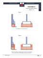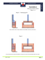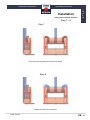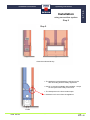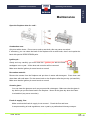
1
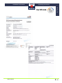
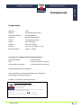
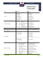
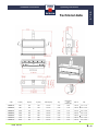
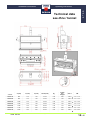
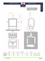
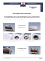
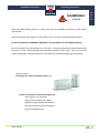
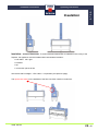
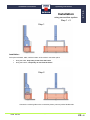
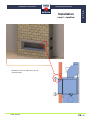
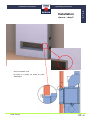
Installation instructions
Operating instructions
GALA®
G
A
L
A
Closed fireplace
for
natural gas
propane
Instal. GALA®
VERO DESIGN NV © all rights reserved
+32 33 85 06 91
1 / 40
Installation instructions
Operating instructions
G
A
L
A
Summary
Introduction
………………………………………………………………………………….
2
Caution
……………………………….……………………………………………….…..
4
Certificates
………………………………………….…………………………………………
5
…………………………….……………………………………………………..
6
Components
Gastechnical instructions
Technical data GALA®
……………………………….……………………………………..
……………….…………………………………….…………………
Summary of delivered material
Air flow
9 - 12
………………………………………………….….…………
13
………………….………………………………………………….…………….……
14
Preparations
…………..………………………………………..……………………………….
Connection
……..………………………………………..…………………….……………
Checking the gas line
……………..…………………………..………………..…………….
Remove and replace the glass frame
Lighting
7-8
15 - 17
18
19
…..……………………………………….……………
19
……………..…………………………………………………………….……………..
20
Installation : general
Insulation
……..…………………………………………………………..…….…..
……..………………………………………………………………..…………..
Installation in a wall
………………………………………………………………………..
Installation in a wall : detailed
………..……………………………………..……...……….
Electrical information
.……………………………………………………..………………
Problems + solutions
………….……………………………………………………..………..
21
22 + 28
23 - 29
30 - 31
32
33 - 36
Warning
………………………………………………………………………………..…..
37
Warranty
………..…………………………………………………………………….……
38
Warranty card
Instal. GALA®
……………………………………………………………………
VERO DESIGN NV © all rights reserved
+32 33 85 06 91
in the back of manaul
2 / 40
Installation instructions
Operating instructions
Introduction
G
A
L
A
Congratulations with your new GALA® gas fireplace. We selected the best materials to produce our
fireplaces. This way you can enjoy your appliance for many years. Before using the GALA, please read
this manual.
CERTIFICATE OF CONFORMITY
VERO DESIGN nv Koralenhoeve 3, Industriepark Noord – 2160 Wommelgem - Belgium
herewith declares that GALA® is produced in accordance with European Security Regulations
90 / 396 EEG.
The appliance can only be installed by a licensed fitter.
Security systems on our fireplaces :
1. Thermo-electrical pilot flame (piëzo)
2. TTB
3. Cold air repercusion safety
4. Infra-red remote control (appliance can not be lighted uncontrolled)
Reinhild Roland
General Manager
Instal. GALA®
VERO DESIGN NV © all rights reserved
+32 33 85 06 91
3 / 40
Installation instructions
Operating instructions
CAUTION !
G
A
L
A
Installation must be performed by a licensed plumber or gas fitter. Installation must comply
with manufacturer’s installation instructions and national and regional instructions.
If you have any doubts, consult your local energy provider.
Before installation, determine if the information on the CE label matches the type of gas and
gaspressure for your region.
Conversion from natural gas to propane (or vice versa) is not
recommended in a more advanced phase.
GALA can be connected to a new or existing chimney vent, using the diameter as
recommended, with natural draft.
GALA can also be connected concentric.
Fresh air supply for combustion from outside or basement. The appliance can be installed in a
normally ventilated house. An extra ventilation system is not necessary.
Vero Design nv is not responsible for manipulated appliances !
Only use the stones which are delivered with the appliance. Place the stones over the burner and
bottom of the fireplace. Make sure there are no stones placed on or against the pilot flame.
Keep flammable materials away from the fireplace (1 m).
Maintenance must be in accordance with regional guidelines, laws and regulations. Although have a
qualified service technician check the appliance once a year. Have your chimney swept once a year
by a qualified chimney-sweeper.
Children or unauthorised persons can only be in the vicinity of the appliance under supervision.
Instal. GALA®
VERO DESIGN NV © all rights reserved
+32 33 85 06 91
4 / 40
Installation instructions
Operating instructions
Certificate
Instal. GALA®
VERO DESIGN NV © all rights reserved
+32 33 85 06 91
G
A
L
A
5 / 40
Installation instructions
Operating instructions
Components
G
A
L
A
Components
Appliance
GALA
Gasbed
Certificate number E1530
Product identificaton
PIN 0063BM1630
Gas block
BM 740/3 modulerating
Transfo
IR (IRT)230Vac-24Vac
Sensor
IR receiver (IRR)
Modubox
MF-301C modubox
Category
I 2E+,I 2H,I 2L,I 2ELL,I 3+,I 3p
Gas line pressure
G20/20 – G25/25
The fireplace is equipped with the following safeties :
Atmospheric safety :
on the pilot flame
TTB :
in connection piece to chimney
Cold air repercusion safety :
in connection piece to chimney
Thermal safety device and gasflexible
GALA is already pre-assembled and tested in our warehouse.
No assembly is requested at the site.
CE label : on the bottom of the technical box
Vero Design NV-Koralenhoeve 3/Industriepark Noord-B 2160 Wommelgem
GALA
SERIAL NR. 120529 TYPE: GA
YEAR 2012
DATE: 17/10/2005 CATEG.: B11 – I2H
Gas line pressure G20/20mbar
Nom. efficiency kW Hi : 26
The appliance has to be installed according the applied regulations can only be used in a sufficient ventilated space.
Read the instructions manual before installing and using the appliance.
Pin : 05-0434-GEE
Land : LV
Type : B11BS
0461/03
Manufacturer : Vero Design NV – Wommelgem, Belgium
Instal. GALA®
tel +32/(0)3.385.06.91
VERO DESIGN NV © all rights reserved
+32 33 85 06 91
6 / 40
Installation instructions
Operating instructions
Gastechnical
instructions
G
A
L
A
DE – Deutschland
Nationale Einbauvorschriften: DVGW-TRGI 86 / 96, technische Regel, Arbeitsblatt G600 bzw TRF
Feu VO der jeweiligen Länderfassung
AT – Österreich
Nationale Einbauvorschriften: ÖVGW – Richtlinien G1 Gas, G2 Flüssiggas
BE – Belgien
Nationale inbouwvoorschriften: NBN D51 – 003 Gas , AREI/RGIE electrititeit
CH – Schweiz
Nationale Einbauvorschriften: SVGW-Gasleitsätze G1 Erdgas, EKAS-Richtlinie 1942 Flüssiggas Teil 2,
Richtlinien der örtlichen Instanzen z.B. Feuerpolizei
Gasanschluss an das öffentlichen Gasnetz darf ausschliesslich mit festen
Gasrohren oder mit einem SVGW-zugelassenen Gassicherheitsschlauch
ausgeführt werden
LU – Luxemburg
Nationale Einbauvorschriften: A-nr. 104 Instalaltions de combustion alimentees en gaz
Instal. GALA®
VERO DESIGN NV © all rights reserved
+32 33 85 06 91
7 / 40
Installation instructions
Operating instructions
Gastechnical
instructions
Gas
Country
appliance category
Natural gas
Propane
AT:Österreich
AT:Österreich
BE: Belgien
BE: Belgien
CH: Schweiz
CH: Schweiz
DE: Deutschland
DE: Deutschland
LUX: Luxemburg
LUX: Luxemburg
NO: Norway
NO: Norway
AT/CH: I2H
Natural gas H
I3P Propane G31
BE:
I2E+
Nat.gas G20 / G25
I3P Propane G31
DE:
I2ELL Nat.gas E/LL
I3P Propane G31
LU:
I2E
Natural gas E
I3P Propane G31
NO:
I2H
Natural gas G20
I3B/P Propane G31
efficiency
NOx classification
65.76 %
64.00%
5
5
G
A
L
A
AT: 50.0 mbar
E / H : 20.0 mbar
CH: 50.0 mbar
LL
DE: 50.0 mbar
: 20.0 mbar
LU: 50.0 mbar
Gas pressure
NO: 30.0 mbar
BE: G20 20 mbar
BE : 37.0 mbar
G25 25 mba
1. atmospheric safety :
1. atmosperic safety :
on the pilot flame
on the pilot flame
2. TTB : in the connection to
Appliance safeties
the chimney
the chimney
3. Cold air repercusion
3. Cold air repercusion
safety : in the connection
safety: in the connection
to the chimney
to the chimney
4. thermal safety device and
gasflexible
Instal. GALA®
2. TTB : in the connection to
VERO DESIGN NV © all rights reserved
4. thermal safety device and
gasflexible
+32 33 85 06 91
8 / 40
Installation instructions
Operating instructions
G
A
L
A
Technical data
code
A (mm)
D (mm)
O (mm)
Gas Ø (mm)
Kg
consumtion
m³/h
natural gas
Gas °C
kW
GALA 1F
800
130
150
15 mm
~120
0.85
155°C
5.0 – 11.0
GALA 2F
900
130
150
15 mm
~130
1.00
180°C
5.0 – 13.0
GALA 3F
1000
130
150
18 mm
~140
1.15
210°C
6.5 – 15.6
GALA 4F
1250
130
150
18 mm
~160
1.40
223°C
6.5 – 17.0
GALA 5F
1500
150
200
22 mm
~170
1.70
292°C
7.0 – 17.8
GALA 6F
1750
180
200
22 mm
~190
2.00
360°C
8.4 – 19.0
GALA 7F
2000
180
200
22 mm
~210
2.30
420°C
8.5 – 20.0
Instal. GALA®
VERO DESIGN NV © all rights reserved
+32 33 85 06 91
9 / 40
Installation instructions
Operating instructions
G
A
L
A
Technical data
see-thru / tunnel
A (mm)
D (mm)
O (mm)
Gas Ø (mm)
Kg
verbuik
m³/h
aardgas
Gas °C
kW
GALA 1D
800
130
150
15 mm
~120
0.85
155°C
5.0 – 11.0
GALA 2D
900
130
150
15 mm
~130
1.00
180°C
5.0 – 13.0
GALA 3D
1000
130
150
18 mm
~140
1.15
210°C
6.5 – 15.6
GALA 4D
1250
130
150
18 mm
~160
1.40
223°C
6.5 – 17.0
GALA 5D
1500
150
200
22 mm
~170
1.70
292°C
7.0 – 17.8
GALA 6D
1750
180
200
22 mm
~190
2.00
360°C
8.4 – 19.0
GALA 7D
2000
180
200
22 mm
~210
2.30
420°C
8.5 – 20.0
Artikelnr.
Instal. GALA®
VERO DESIGN NV © all rights reserved
+32 33 85 06 91
10 / 40
Installation instructions
Operating instructions
G
A
L
A
Technical data
square
code
A (mm)
D (mm)
O (mm)
Gas Ø (mm)
Kg
Gas m³/h
°C
kW
GALA 70 F
700
130
150
15
~110
0.73
220°C
5.0 – 11.0
GALA 80 F
800
130
150
15
~125
0.80
230°C
5.0 – 13.0
GALA 90 F
900
130
150
18
~140
0.85
238°C
6.5 – 15.6
Instal. GALA®
VERO DESIGN NV © all rights reserved
+32 33 85 06 91
11 / 40
Installation instructions
Operating instructions
G
A
L
A
Technical data
square tunnel
code
A (mm)
D (mm)
O (mm)
Gas Ø (mm)
Kg
Gas m³/h
°C
kW
GALA 70 D
700
130
150
15
~110
0.73
220°C
5.0 – 11.0
GALA 80 D
800
130
150
15
~125
0.80
230°C
5.0 – 13.0
GALA 90 D
900
130
150
18
~140
0.85
238°C
6.5 – 15.6
Instal. GALA®
VERO DESIGN NV © all rights reserved
+32 33 85 06 91
12 / 40
Installation instructions
Operating instructions
G
A
L
A
Delivered material
Before you unpack the fireplace, check packaging for damages. In case of damage, contact us at
+32/33.85.06.91. If possible send a picture of the damage to : [email protected]
Delivered goods :
•
GALA fireplace, entirely pre-assembled
•
Convection system with 2 warm and 2 cold air connections
•
100 cm RTD gasflexible
– already assembled on the fireplace
•
100 cm EU plug
– already assembled on the fireplace
•
Repercussion safety
•
4 adjustable feet
- already assembled on the fireplace
•
1 box with decoration material
- only use the delivered material :
is part of total
•
1 infra-red remote control, incl. batteries
•
Installation instructions and warranty card
approvement of fireplace
– all electronic parts are already installed
Be sure that all parts were delivered. If not, please contact us at : +32/33.85.06.91
Remove packaging. You will find the stones, the remote control, installation and operating instructions,
warranty papers in the cardboard box.
Installation of GALA only in a dry building. Moist areas can cause damage to the electronic parts.
GALA fireplaces are tested individually, properly and lighted in our workshop.
Instal. GALA®
VERO DESIGN NV © all rights reserved
+32 33 85 06 91
13 / 40
Installation instructions
Operating instructions
Air flow
G
A
L
A
Combustion air
Fresh air, combustion air, primary air, has to be brought into the unit. This is possible from a different
place under the unit or via a tube from an outside wall.
Supply the unit
with combustion air from underneath, do not connect.
The air will find ist way into the burner by several openings.
Convection air system
When the convection air system is not wanted, close the openings on the unit with insulation material.
This is how the convection air system has to be connected :
1 or 2 warm air vent
CONNECT !
Warm air will get into the room
again via the vent
1 or 2 col air vent
CONNECT !
Air from the room will go
into the convection
chamber and warms up
Instal. GALA®
!
VERO DESIGN NV © all rights reserved
+32 33 85 06 91
14 / 40
Installation instructions
Operating instructions
!
G
A
L
A
Preparations
GALA has to be connected to an existing or new flue.
GALA® IS NOT CONNECTED CONCENTRIC :
The appliance draws combustion air from outside. Before installation, be sure that your flue is suitable for
the ordered appliance. The flue ends outside.
Have your flue swept by a certified chimney-sweeper !
Flue - situation 1
Flue - situation 2
Instal. GALA®
VERO DESIGN NV © all rights reserved
+32 33 85 06 91
15 / 40
Installation instructions
Operating instructions
G
A
L
A
Preparing
airflow
Before installation: with or without airflow
GALA® is equiped with 2 (1 x right + 1 x left) cold air entrances and 2 (1 x right + 1 x left) warm air outlets.
If you connect the airflow system, there will be a better, natural circulation of the warm air in the room
where the fireplace will be installed. There is no fan used.
The perforation has
already been done.
Turn the perforated piece until it loosens. Now you can
Put the delivered connection pieces in the holes.
take away the perforated piece.
Then bow on the inside.
The connection pieces
are installed.
Instal. GALA®
VERO DESIGN NV © all rights reserved
+32 33 85 06 91
16 / 40
Installation instructions
Operating instructions
G
A
L
A
Preparations
GALA® Install the fireplace on a flat surface. Installation conform local fire safety instructions!
By using the adjustable feet, you can level the fireplace.
Flue - vertical termination :
Install the fireplace underneath, centered the flue and in the center of the fresh air supply. Socket on the
right, max. 100 cm from the fireplace. Gas line, in recommended Ø on the right of the appliance.
Connect gas hose to gasline. (1, pag. 15).
Instal. GALA®
VERO DESIGN NV © all rights reserved
+32 33 85 06 91
17 / 40
Installation instructions
Operating instructions
G
A
L
A
Gas connection
Flue – Horizontal termination :
Install the appliance so that only one 45° elbow is used. Socket on the right side (see pag. 14) of the
appliance, gas line on the right side of the fireplace and shut off with terminal safety device (1) (see
example underneath).
Connect and test !!!
Put the plug in the socket, put gas hose (2) in therminal safety device (1)
1
and turn until you see a green arrow.
Connect the appliance to the chimney vent using the recommended
2
diameter.
Purge the gasline and check for gas leaks.
GALA® - Cover the burner and bottom of combustion chamber only with the
delivered stones. Make sure that the pilot flame remains free.
Instal. GALA®
VERO DESIGN NV © all rights reserved
+32 33 85 06 91
18 / 40
Installation instructions
Operating instructions
G
A
L
A
Checking the
gaslines
Purge the air from the gaslines.
Check for gas leaks by using a qualified gas tester.
GALA® - Only light the appliance when all lines are closed !
GALA® - Cover the burner and the bottom of the combustion chamber with the
delivered stones.
They are part of the entire CE
approval
of the appliance.
Put max. 2 layers of pebbles and keep the rest seperately.
Make sure that the pilot flame remains free !
Removing and
replacing glass frame
Instal. GALA®
VERO DESIGN NV © all rights reserved
+32 33 85 06 91
19 / 40
Installation instructions
Operating instructions
Lighting the
fireplace
G
A
L
A
When first operated, the appliance may release an odor. This is
caused by the curing of the paint. This is a normal result. Ventilate
the room properly !
ONLY LIGHT THE
FIREPLACE WHEN
GLASS IS INSTALLED
GALA® The fireplace is controlled with a FULL-OPTION infra red
remote control. The remote has a reach of ~4.00m.
FULL-OPTION means :
The appliance is lid from the OFF position of the pilot flame.
Aim the remote control towards the infra red receiver. You will find
the infra red receiver in the middle of the lower side of the frontal
frame.
Always keep the pilot flame free from stones. Do not put any
decoration material against or on the pilot flame !
LIGHTING
1. Press buttons 3 and 4 at the same time during 3 sec.
2. Meanwhile the LED-indication on the remote control lights 3 sec.
3. The pilot flame ignites. You hear a „click“ followed by „tic, tic, tic“.
The order to light has been recognized and the securities are
activated.
Direction
LED 1
B-6
B-5
B-4
B-1
4. The pilot flame ignites and starts to burn. The flame lights the gas
in the burner starting from the middle to the sides. Wait for the
gaspressure in the burner to build up, so it burns over the whole
lenght. This could take up to 20 seconds, depending on the size
of the burner.
B-2
B-3
5. Higher flames : keep pressing button 1 until the desired height of
flames is reached. The maximum available height depends on
local gaspressure and the amount of gas that’s feeding the
appliance (Ø gasline).
6. Lower flames : keep pressing button 2.
7. Button 5 activates automatic modulation
SWITCH OFF
1. Press button 4. The pilot flame and the burner extinguish slowly
until all remaining gas is burned. Once they are extinguished,
there is no more use of gas.
RESET + INTERRUPTION
Press buttons 3 and 4 more than 3 sec. at the same time. The
system changes from interruption to standy. The LED lids during 3
sec.
Instal. GALA®
VERO DESIGN NV © all rights reserved
+32 33 85 06 91
20 / 40
Installation instructions
Operating instructions
!
G
A
L
A
Installation
General
When the fireplace will be build in in a tiled stove, follow the installation instructions of the relating
manufacturer !
When the fireplace will be build in in a brick wall or other, you must use heat-resistant insulation !
DO NOT PLACE ANY FLAMMABLE MATERIAL ON THE INSIDE OF THE CHIMNEY-PIECE !
By using insulation, the heat spreads more controlled : Through the glass and if wanted, also through
the warm air vents, without damaging heat-sensitive materials in the vicinity. This way you avoid
cracks and damage in the bricks and stucco work because of the heat stowage and heat transfer.
We recommend :
Promaglaf HTI thickness 25,4mm 100kg / m³
Profits and qualities of Promat Promaglaf HTI:
work hygienic, non classified
highly thermal resistant upto 1260°C
resistant to high temperature fluctuation
low heat conduction and heat absorption
free from unpleasant odor
Instal. GALA®
VERO DESIGN NV © all rights reserved
+32 33 85 06 91
21 / 40
Installation instructions
Operating instructions
G
A
L
A
Insulation
Insulation : all blue marked areas. To avoid unwanted heat transfer to materials in the vicinity of the
fireplace, the appliance must be insulated with heat-resistant insulation :
• both sides
left / right
• backside
• top
• connenction pieces to flue
We recommend Promaglaf – HTK 1260°C or equivalent (see previous page)
The repercusion safety on the backside of the flue connection needs to remain free.
Instal. GALA®
VERO DESIGN NV © all rights reserved
+32 33 85 06 91
22 / 40
Installation instructions
Operating instructions
Installation
using convection system
G
A
L
A
Step 1 + 2
Step 1
Installation :
Pull up the brickwork, walls, until the bottom of the cold air connection piece
•
along the sides, keep away 10 mm from the frame
•
along the bottom, keep away 10 mm from the frame
Step 2
Connect the cold air grilles to the connection pieces (150 mm) with a flexible tube.
Instal. GALA®
VERO DESIGN NV © all rights reserved
+32 33 85 06 91
23 / 40
Installation instructions
Operating instructions
Installation
using convection system
G
A
L
A
Step 3 + 4
Step 3
Put insulation on connection pieces.
Step 4
Place the air grilles according to the manufacturer’s instructions.
Pull up the brickwork until 10 mm from the top of the frame.
Instal. GALA®
VERO DESIGN NV © all rights reserved
+32 33 85 06 91
24 / 40
Installation instructions
Operating instructions
G
A
L
A
Installation
using convection system
Step 5 + 6
Step 5 / Detail page 26
Place a beam across. Keep a distance from 10 mm from the top of the frame.
Step 6
Pull up the brickwork so that the flexibles for the warm air can be connected fluently with a 90° elbow.
Instal. GALA®
VERO DESIGN NV © all rights reserved
+32 33 85 06 91
25 / 40
Installation instructions
Operating instructions
Installation
using convection system
G
A
L
A
Step 7 + 8
Step 7
Place the warm air grilles and connect with aluflex.
Step 8
Insulate the warm air connections.
Instal. GALA®
VERO DESIGN NV © all rights reserved
+32 33 85 06 91
26 / 40
Installation instructions
Operating instructions
G
A
L
A
Installation
using convection system
Step 9
Step 9
Close the walls and let dry.
• The appliance is placed against a wall and on the
floor according local fire safety regulations.
• GALA is covered completely with insulation : except
for the repercusion safety on the back.
• The interspace on the front remains open.
• Brickwork until 10 mm from the appliance.
Profile
Instal. GALA®
VERO DESIGN NV © all rights reserved
+32 33 85 06 91
27 / 40
Installation instructions
Operating instructions
G
A
L
A
Installation
not using convection
system
The appliance has to be covered with insulation (all blue marked areas), including the connection pieces for
the air. The repercusion safety on the back of the fireplace remains free.
Build in the appliance as mentionned on the previous pages, with exception of the grilles.
After GALA has been build in, you can’t ingnite the appliance immediately.
The duration for the materials to dry can take upto 4 weeks.
Pay attention to the instructions of your professional dealer !
Instal. GALA®
VERO DESIGN NV © all rights reserved
+32 33 85 06 91
28 / 40
Installation instructions
Operating instructions
Installation
step 5 : detailled
G
A
L
A
Brickwork on the 4 sides upto 10 mm
from the frame.
Instal. GALA®
VERO DESIGN NV © all rights reserved
+32 33 85 06 91
29 / 40
Installation instructions
Operating instructions
Installation
stucco - step 1
G
A
L
A
Place an L-profile, upto 3 mm from the
appliance.
Stucco the brickwork / wall.
By using an L-profile you obtain an exact
shadowjoint.
Instal. GALA®
VERO DESIGN NV © all rights reserved
+32 33 85 06 91
30 / 40
Installation instructions
Operating instructions
Installation
stucco – step 2
G
A
L
A
Stucco brickwork / wall.
By using an L-profile you obtain an exact
shadowjoint.
Instal. GALA®
VERO DESIGN NV © all rights reserved
+32 33 85 06 91
31 / 40
Installation instructions
Operating instructions
G
A
L
A
Electronic
schedule
You find all electronic parts in the “technical box”. The box is situated in the middle on the
bottom of the combustion chamber of the appliance. Remove the glass (see page 16) and the
stones. Open the lid of the technical box.
Stromstecker
Transfo
Gassicherheitsventiel
Modubox - modulating
Brennerautomat
modulierend
Gas hose
with
thermal safety device
Gas valve
IR
Fernbedienung
IR remote
Starter
Piezo –/ Ioniserung
pilot flame
Zündflamme
Oxy-pîlot
Burner
Instal. GALA®
VERO DESIGN NV © all rights reserved
+32 33 85 06 91
32 / 40
Installation instructions
Operating instructions
G
A
L
A
Problems and solutions
Flames
The first person to contact is your professional dealer.
LED 1
LED-indication on the remote control does not light up when lighting
Replace batteries ( 2 x 1.5V, AAA, LR03)
B-6
B-1
B- 5
B-2
B- 4
B-3
The remote control does not respond
Replace batteries ( 2 x 1.5V, AAA, LR03).
The receiver does not registrate the signal : move closer to the appliance and
point at the opening in the middle of the lower frame.
Make sure that the infra-red eye is not covered.
The fireplace does not light
Put the plug in the socket.
Press buttons 3 and 4 at the same time for about 15 sec., the LED-indication lights
5 times.
After the pilot flame has extinguished, you must wait at least 5 minutes before you can
restart.
Do not manipulate the ingnition pin of the pilot flame !
The fireplace ignites but there are no flames
Open the gasline.
After a period that the fireplace has not burnt, the gasline is empty. By restarting the
fireplace, the gasline is purged and removes the air in the gasline. This can take a while,
depending on the lenght of the gasline.
Remove the stones on or against the pilot flame.
The fireplace ignites, pilot flame burns but extinguishes immediately
Remove the stones on or against the pilot flame.
Insulation that is put around the pilot flame has to be checked and put back in its place,
if necessary it has to be replaced.
Mechanism of the pilot flame needs to be replaced (by fitter).
Instal. GALA®
VERO DESIGN NV © all rights reserved
+32 33 85 06 91
33 / 40
Installation instructions
Operating instructions
G
A
L
A
Problems and solutions
Flames
Condensation on the glass, right after lighting the fireplace
This is normal when the fireplace is still cold or cooled down. After a few seconds
the condensation disappears.
The flames in the middle are higher than the ones on the sides
Spread the stones again, if necessary put lesser stones.
There has been some time between installing and lighting the fireplace for the first time :
Because of the humidity and dust, the wholes in the burner may be blocked.
Clean the appliance with a vacuumcleaner. Open the wholes with a pointed object,
e.g. a small nail. Devide the stones equally over the burner and bottom of the
combustion chamber.
The appliance does not burn clean and the flames are too high
There has been ordered an appliance for natural gas, but you are using propane :
The burner can only be replaced by our technician. Contact your fitter.
Position “high flames” only gives small flames
There has been ordered an appliance for propane, but you are using natural gas :
The burner can only be replaced by our technician. Contact your fitter.
The flames do not respond when changing the position high/low
Keep pressing button 3 or 4 on the remote control during 15 seconds. The gasvalve
in the appliance will now react and adapt the gaspressure in the burner.
The appliance burns, but extinguishes suddenly without any reason
For some reason, a safety has interrupted the gas supply. Trace the cause of it :
is there enough fresh air, is the vent free?
After the pilot flame has extinguished, you have to wait for 5 minutes before you
can restart the fireplace.
Instal. GALA®
VERO DESIGN NV © all rights reserved
+32 33 85 06 91
34 / 40
Installation instructions
Operating instructions
G
A
L
A
Problems and solutions
General
After the appliance is lit, there’s an odor coming from the appliance
When first operated, the appliance may release an odor. This is caused by the curing
of the paint. This is a normal result! Ventilate the room thoroughly.
The air grilles (on top) draw air
The grilles, warm / cold air, are not connected to the fireplace.
Contact your professional dealer and have the grilles connected or close / cover the
connection pieces.
The stucco on the wall shows bursts on the frontside
The appliance has not been properly covered with insulation or not insulated at all.
The consequences are that there is heat transfer to the other materials. Contact your
professional dealer.
A black, rusty dust is forming against the warm air grilles
The cold air grilles absorb small dust parts. Because of the air warming up, the dust
parts warm up as well and mingle with the warm air which leaves through the air grilles.
Then the dust parts cool off and settle on the appliance. Dust the grilles as often as
possible with a duster and use a vacuumcleaner.
The corners on the frontside of the fireplace are damaged
The brickwork or stucco has been done too close to the fireplace. Contact your.
professional dealer.
Dirt is falling into your fireplace
Have your flue swept by a professional chimney-sweeper.
By using propane gas, a black fumagine layer may occur.
The glass (ceramic) is damaged
Swith off the fireplace immediately! Never lite the fireplace with damage on the glass!
Make sure you order a new glass with your professional dealer.
Instal. GALA®
VERO DESIGN NV © all rights reserved
+32 33 85 06 91
35 / 40
Installation instructions
Operating instructions
Problems and solutions
General
G
A
L
A
The paint is showing some damage
You can order special VERO DESIGN paint spray at your professional dealer shop.
This way you can repaint the damaged parts.
The appliance does not heat sufficiently
There has not been used enough insulation. The convection system has not been
connected. Contact your professional dealer.
Instal. GALA®
VERO DESIGN NV © all rights reserved
+32 33 85 06 91
36 / 40
Installation instructions
Operating instructions
G
A
L
A
Maintenance
Open the fireplace when it’s cold :
Combustion area :
Only dust with a duster. Do not use a moist or wet cloth, this may cause corrosion!
If necessary, you can clean the back of the fireplace with a steel brush, dust it and repaint the
back with special VERO DESIGN paint.
Ignition pin :
Gently and very carefully you must clean the ignition pin with the finest
sandpaper once a year. All the dust and corrosion will be removed.
Make sure that the ignition pin never bends or moves!
Decoration material :
Remove the stones from the fireplace and put them in water with detergent. Clean them and
rinse them with cold water. Put the stones back on the fireplace after they are dry (at least 24h).
Make sure that the ignition pin never bends or moves!
Ceramic glass :
You can clean the glass as much as you want with a detergent. Make sure that the glass is
dry before you put the frame back in the fireplace. Never let the glass dry when the frame
is reinstalled (may cause corrosion).
Fresh air supply, flue :
Make sure that the fresh air supply is not covered . Check the flue and have
it swept according to local regulations, once a year by a professional chimney-sweeper.
Instal. GALA®
VERO DESIGN NV © all rights reserved
+32 33 85 06 91
37 / 40
Installation instructions
Operating instructions
G
A
L
A
Warranty
2
Vero Design NV wishes to thank you for your trust and guarantees you that the fireplace GALA gas is
made with utmost care and manufactured with the best materials.
The warranty includes all production errors and the functioning of the appliance over a period of 2 years
starting from the date of installation. You will find the warranty card on the last page of this manual. The
warranty card has to filled out by your professional dealer and send back to the manufacturer.
If, in spite of normal use, a malfunction occurs within the warranty period of 2 years, due to material and /
or production error, the part will be replaced by a new one, free of charge by the supplier.
The defective part, mentionning appliance number, date of installation and appliance type, has to be send
back to Vero Design NV, Koralenhoeve 3, BE – 2160 Wommelgem. The number of the appliance you will
find on the CE label inside the fireplace and also on the warranty card.
Warranty is not valid if damage is completely or partly due to :
•
Not following the installation, service and warning regulations
•
Manipulation or roughly treatment of the appliance
•
Installation or repair by a third party, e.g. the buyer
•
Cracks and damage appear on the chimney-piece
•
Colouring of the materials
•
Changing owner
Warranty excludes :
Ceramic glass
Thermal element
Attention : when using propane gas, a fumagine layer may occur on the stones.
Repairs do not renew and / or extend the warranty period. Every damage consequence is excluded.
Fees and supplementary costs cannot be invoiced to Vero Design, nor can Vero Design be held
responsible for this.
Instal. GALA®
VERO DESIGN NV © all rights reserved
+32 33 85 06 91
38 / 40
Installation instructions
Operating instructions
Accessories
G
A
L
A
MF-310 C Modubox
Gas valve GB-055
Infra-red remote control
Infra-red receiver
Cables
Instal. GALA®
VERO DESIGN NV © all rights reserved
+32 33 85 06 91
39 / 40
Installation instructions
Operating instructions
Accessories
G
A
L
A
Paint spray - colour 930
4 adjustable feet
Decoration white – Carrara marmer
Decoration grey
Decoration ceramic wood
Instal. GALA®
VERO DESIGN NV © all rights reserved
+32 33 85 06 91
40 / 40