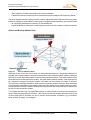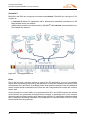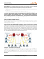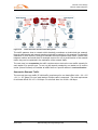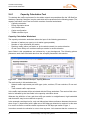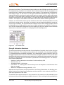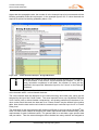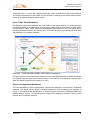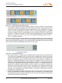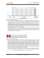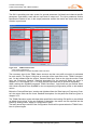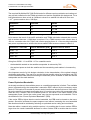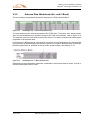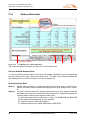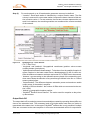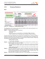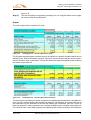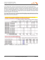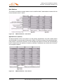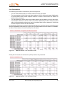
1
SkyWAN® Indoor Unit IDU 7000 Series IDU 7000, Software Rel. 7.11 IDU 2570, Software Rel. 7.11 IDU 2070, Software Rel. 7.11 IDU 1070 Series IDU 1070, Software Rel. 1.11 Network Design and Engineering Guide Document Number OM2044E_9400711 Document Revision B Revision Date 2010-10-26 ND SatCom Product GmbH Graf-von-Soden-Strasse 88090 Immenstaad Germany Phone: E-Mail: +49 (0)7545 939 0 [email protected] This document is protected by copyright law. This document is the property of ND SatCom Product GmbH (hereafter referred to as ’ND SatCom’), which reserves all rights. This document or parts of it may not be reproduced, duplicated or distributed to third parties. Nor may their content be disclosed to third parties without the express written approval of ND SatCom Product GmbH. Misuse will be subject to legal action and fines. All rights to patents and utility models are reserved. MANUAL CONVENTIONS There are a few graphical symbols and formatting conventions used to show information clearly arranged and easy to find. Symbol used for Information Symbol is used to notify a user of special or useful information. i Action Item Action Items are used to direct the user to execute the steps in the given order for a successful completion of the action. Prerequisite Step (1) Step (2) action step 1 action step 2 fulfilled precondition for successful action completion Step (1) perform described action (1) Step (2) perform described action (2) Action objective after finishing action steps Action objective reached string (word, number) in code formatting Type this word, number or string as input, i.e. as command line or in a tool input field. <string_A> The <string_A> between the brackets is placeholder for a variable. Fill in the contents of the placeholder without brackets. ’string_B’ As quoted string ’string_B’ names and labels are presented: e.g. name of a variable, a window or field name, label of a button. Screenshots may not always contain valid data. Slight differences may occur in the graphical presentation shown (i.e. in the Graphical User Interface (GUI) of a program). 2010-10-26 Network Design and Engineering Guide 1 Page intentionally left blank 2 Network Design and Engineering Guide 2010-10-26 TABLE OF CONTENTS Manual Conventions . . . . . . . . . . . . . . . . . . . . . . . . . . . . . . . . . . . . . . . . . . . . . . . . 1 Table of Contents. . . . . . . . . . . . . . . . . . . . . . . . . . . . . . . . . . . . . . . . . . . . . . . . . . . 3 List of Tables . . . . . . . . . . . . . . . . . . . . . . . . . . . . . . . . . . . . . . . . . . . . . . . . . . . . . . 7 List of Figures . . . . . . . . . . . . . . . . . . . . . . . . . . . . . . . . . . . . . . . . . . . . . . . . . . . . . 9 1 Introduction. . . . . . . . . . . . . . . . . . . . . . . . . . . . . . . . . . . . . . . . . . . . . 13 1.1 Summary . . . . . . . . . . . . . . . . . . . . . . . . . . . . . . . . . . . . . . . . . . . . . . . . . . . . 13 1.2 Manual Content . . . . . . . . . . . . . . . . . . . . . . . . . . . . . . . . . . . . . . . . . . . . . . . 13 1.2.1 Who should read this document . . . . . . . . . . . . . . . . . . . . . . . . . . . . . . . . 14 1.2.2 What do you need to know . . . . . . . . . . . . . . . . . . . . . . . . . . . . . . . . . . . . 14 1.3 SkyWAN® Solutions and Benefits . . . . . . . . . . . . . . . . . . . . . . . . . . . . . . . . . 15 1.4 General Design and Engineering Process . . . . . . . . . . . . . . . . . . . . . . . . . . . 16 1.5 Related Documents . . . . . . . . . . . . . . . . . . . . . . . . . . . . . . . . . . . . . . . . . . . . 17 1.5.1 SkyWAN® IDU Manuals Suite . . . . . . . . . . . . . . . . . . . . . . . . . . . . . . . . . . 17 2 General Carrier Design. . . . . . . . . . . . . . . . . . . . . . . . . . . . . . . . . . . . 19 2.1 Introduction. . . . . . . . . . . . . . . . . . . . . . . . . . . . . . . . . . . . . . . . . . . . . . . . . . . 19 2.2 Data and Voice Networking Overview . . . . . . . . . . . . . . . . . . . . . . . . . . . . . . 20 Voice connections . . . . . . . . . . . . . . . . . . . . . . . . . . . . . . . . . . . . . . . . . 21 Voice Codecs . . . . . . . . . . . . . . . . . . . . . . . . . . . . . . . . . . . . . . . . . . . . 22 2.3 2.3.1 Essential SkyWAN® Satellite Link Layer Features. . . . . . . . . . . . . . . . . . . . . 23 SkyWAN® Network Topologies . . . . . . . . . . . . . . . . . . . . . . . . . . . . . . . . . 23 Reception Modes . . . . . . . . . . . . . . . . . . . . . . . . . . . . . . . . . . . . . . . . . 24 2.3.2 Master and Slave Functionality . . . . . . . . . . . . . . . . . . . . . . . . . . . . . . . . . 25 Control Communication: Reference and Request Bursts . . . . . . . . . . . 25 Active and Backup Master Role . . . . . . . . . . . . . . . . . . . . . . . . . . . . . . 26 2.3.3 SkyWAN® MF-TDMA functionality. . . . . . . . . . . . . . . . . . . . . . . . . . . . . . . 27 TDMA Frame. . . . . . . . . . . . . . . . . . . . . . . . . . . . . . . . . . . . . . . . . . . . . Transmit and Receive Carriers . . . . . . . . . . . . . . . . . . . . . . . . . . . . . . . Data Slot Time Factors . . . . . . . . . . . . . . . . . . . . . . . . . . . . . . . . . . . . . TDMA Superframe . . . . . . . . . . . . . . . . . . . . . . . . . . . . . . . . . . . . . . . . 27 28 29 30 2.3.4 Downlink and Uplink Populations . . . . . . . . . . . . . . . . . . . . . . . . . . . . . . . 30 2.3.5 SkyWAN® Reference Burst Modes . . . . . . . . . . . . . . . . . . . . . . . . . . . . . . 31 MRB Mode . . . . . . . . . . . . . . . . . . . . . . . . . . . . . . . . . . . . . . . . . . . . . . 31 MRB-DUB Mode . . . . . . . . . . . . . . . . . . . . . . . . . . . . . . . . . . . . . . . . . . 31 NFB-DUB Mode . . . . . . . . . . . . . . . . . . . . . . . . . . . . . . . . . . . . . . . . . . 32 2.3.6 Capacity Request and Allocation for User Data . . . . . . . . . . . . . . . . . . . . 33 Free Slot Assignment . . . . . . . . . . . . . . . . . . . . . . . . . . . . . . . . . . . . . . Ranging Subframe . . . . . . . . . . . . . . . . . . . . . . . . . . . . . . . . . . . . . . . . Stream Slots . . . . . . . . . . . . . . . . . . . . . . . . . . . . . . . . . . . . . . . . . . . . . Dynamic Slots . . . . . . . . . . . . . . . . . . . . . . . . . . . . . . . . . . . . . . . . . . . . 2010-10-26 Network Design and Engineering Guide 33 34 34 35 3 2.3.7 Guaranteed Throughput . . . . . . . . . . . . . . . . . . . . . . . . . . . . . . . . . . . . . . .36 Guaranteed Throughput Example Scenarios . . . . . . . . . . . . . . . . . . . . Scenario 1 . . . . . . . . . . . . . . . . . . . . . . . . . . . . . . . . . . . . . . . . . . . . . . Scenario 2 . . . . . . . . . . . . . . . . . . . . . . . . . . . . . . . . . . . . . . . . . . . . . . Scenario 3 . . . . . . . . . . . . . . . . . . . . . . . . . . . . . . . . . . . . . . . . . . . . . . Scenario 4 . . . . . . . . . . . . . . . . . . . . . . . . . . . . . . . . . . . . . . . . . . . . . . 2.4 36 37 38 39 40 Network Traffic Estimation. . . . . . . . . . . . . . . . . . . . . . . . . . . . . . . . . . . . . . . .41 Traffic Profiles . . . . . . . . . . . . . . . . . . . . . . . . . . . . . . . . . . . . . . . . . . . 41 Traffic Estimation Example Scenario . . . . . . . . . . . . . . . . . . . . . . . . . . 42 Summarize Example Traffic . . . . . . . . . . . . . . . . . . . . . . . . . . . . . . . . . 43 2.4.1 Capacity Calculation Tool . . . . . . . . . . . . . . . . . . . . . . . . . . . . . . . . . . . . . .44 Capacity Calculation Worksheet . . . . . . . . . . . . . . . . . . . . . . . . . . . . . Erlang B Calculation Worksheet. . . . . . . . . . . . . . . . . . . . . . . . . . . . . . Voice Traffic Flow Worksheet. . . . . . . . . . . . . . . . . . . . . . . . . . . . . . . . Carrier Configuration Worksheet . . . . . . . . . . . . . . . . . . . . . . . . . . . . . 2.4.2 2.5 2.5.1 2.6 44 45 47 47 Limitations of the Traffic Estimation Approach . . . . . . . . . . . . . . . . . . . . . .49 From User Traffic to Satellite Link Carriers . . . . . . . . . . . . . . . . . . . . . . . . . . .51 Summary. . . . . . . . . . . . . . . . . . . . . . . . . . . . . . . . . . . . . . . . . . . . . . . . . . .54 TDMA Carrier Design with ’TDMA Calculator’ . . . . . . . . . . . . . . . . . . . . . . . . .55 2.6.1 Section ’General Data Input’ . . . . . . . . . . . . . . . . . . . . . . . . . . . . . . . . . . . .57 2.6.1.1 Parameter Summary . . . . . . . . . . . . . . . . . . . . . . . . . . . . . . . . . . . . . . . . . .58 2.6.2 Section ’Data Input per Frequency Channel’ . . . . . . . . . . . . . . . . . . . . . . .59 2.6.2.1 Parameter Summary . . . . . . . . . . . . . . . . . . . . . . . . . . . . . . . . . . . . . . . . . .60 2.6.3 Area ’General Data Output’. . . . . . . . . . . . . . . . . . . . . . . . . . . . . . . . . . . . .62 2.6.3.1 Parameter Summary . . . . . . . . . . . . . . . . . . . . . . . . . . . . . . . . . . . . . . . . . .62 2.6.4 Area ’Data output per frequency channel’. . . . . . . . . . . . . . . . . . . . . . . . . .63 2.6.4.1 Parameter Summary . . . . . . . . . . . . . . . . . . . . . . . . . . . . . . . . . . . . . . . . . .65 2.6.5 Exporting and Importing TDMA Calculator Values . . . . . . . . . . . . . . . . . . .66 2.7 From Capacity Estimation to TDMA Structure. . . . . . . . . . . . . . . . . . . . . . . . .67 One Carrier Solution. . . . . . . . . . . . . . . . . . . . . . . . . . . . . . . . . . . . . . . Adjustment and Optimization Considerations . . . . . . . . . . . . . . . . . . . Optimized Three Carrier Solution . . . . . . . . . . . . . . . . . . . . . . . . . . . . . Adjustment and Optimization Considerations . . . . . . . . . . . . . . . . . . . 68 68 69 69 3 Outdoor Unit and Satellite Link Design . . . . . . . . . . . . . . . . . . . . . .73 3.1 Introduction . . . . . . . . . . . . . . . . . . . . . . . . . . . . . . . . . . . . . . . . . . . . . . . . . . .73 Select Satellite Transponder . . . . . . . . . . . . . . . . . . . . . . . . . . . . . . . . 73 Calculate Link Budget . . . . . . . . . . . . . . . . . . . . . . . . . . . . . . . . . . . . . 74 Perform Optimization . . . . . . . . . . . . . . . . . . . . . . . . . . . . . . . . . . . . . . 74 3.2 Satellite Beam Footprints. . . . . . . . . . . . . . . . . . . . . . . . . . . . . . . . . . . . . . . . .74 Satellite Choice Considerations . . . . . . . . . . . . . . . . . . . . . . . . . . . . . . 75 3.3 Fundamentals of Link Budget Calculation . . . . . . . . . . . . . . . . . . . . . . . . . . . .76 Uplink and Downlink . . . . . . . . . . . . . . . . . . . . . . . . . . . . . . . . . . . . . . . 76 Equivalent Isotropic Radiated Power (EIRP) and Antenna Gain . . . . . 76 4 Network Design and Engineering Guide 2010-10-26 Path Loss . . . . . . . . . . . . . . . . . . . . . . . . . . . . . . . . . . . . . . . . . . . . . . . Saturation Flux Density (SFD) . . . . . . . . . . . . . . . . . . . . . . . . . . . . . . . Noise, Figure of Merit G/T and Signal-to-Noise Ratio Eb/No . . . . . . . . Satellite Link Quality Dependencies . . . . . . . . . . . . . . . . . . . . . . . . . . . Power Equivalent Bandwidth . . . . . . . . . . . . . . . . . . . . . . . . . . . . . . . . Rain fade. . . . . . . . . . . . . . . . . . . . . . . . . . . . . . . . . . . . . . . . . . . . . . . . Rain Margin and Uplink Power Control . . . . . . . . . . . . . . . . . . . . . . . . . 3.4 77 77 77 77 78 79 80 Considerations for SkyWAN® Link Budget Calculations . . . . . . . . . . . . . . . . 82 3.4.1 Network Topology . . . . . . . . . . . . . . . . . . . . . . . . . . . . . . . . . . . . . . . . . . . 82 3.4.2 Downlink Optimization . . . . . . . . . . . . . . . . . . . . . . . . . . . . . . . . . . . . . . . . 83 3.4.3 Uplink Optimization . . . . . . . . . . . . . . . . . . . . . . . . . . . . . . . . . . . . . . . . . . 84 3.5 SkyWAN® Link Budget Calculation Tool . . . . . . . . . . . . . . . . . . . . . . . . . . . . 85 3.5.1 Satellite Data Worksheets (Ku- and C-Band) . . . . . . . . . . . . . . . . . . . . . . 86 3.5.2 Antenna Data Worksheets (Ku- and C-Band) . . . . . . . . . . . . . . . . . . . . . . 87 3.5.3 Stations Worksheet . . . . . . . . . . . . . . . . . . . . . . . . . . . . . . . . . . . . . . . . . . 88 Use pre-defined Network Data . . . . . . . . . . . . . . . . . . . . . . . . . . . . . . . Specify Network Data . . . . . . . . . . . . . . . . . . . . . . . . . . . . . . . . . . . . . . Output Back-Off . . . . . . . . . . . . . . . . . . . . . . . . . . . . . . . . . . . . . . . . . . Stations with 2 Demodulator Boards. . . . . . . . . . . . . . . . . . . . . . . . . . . 88 88 89 90 3.5.4 Tx Amplifier Worksheet . . . . . . . . . . . . . . . . . . . . . . . . . . . . . . . . . . . . . . . 91 3.5.5 Summary Worksheet . . . . . . . . . . . . . . . . . . . . . . . . . . . . . . . . . . . . . . . . . 92 Input . . . . . . . . . . . . . . . . . . . . . . . . . . . . . . . . . . . . . . . . . . . . . . . . . . . 92 Output . . . . . . . . . . . . . . . . . . . . . . . . . . . . . . . . . . . . . . . . . . . . . . . . . . 93 Optional Link Filter for Complex Topologies . . . . . . . . . . . . . . . . . . . . . 95 3.5.6 Required Settings for MRB-DUB Networks . . . . . . . . . . . . . . . . . . . . . . . . 95 Transponder Data . . . . . . . . . . . . . . . . . . . . . . . . . . . . . . . . . . . . . . . . . Hub Stations . . . . . . . . . . . . . . . . . . . . . . . . . . . . . . . . . . . . . . . . . . . . . UpLink Area 1 (ULA1) . . . . . . . . . . . . . . . . . . . . . . . . . . . . . . . . . . . . . . UpLink Area 2 (ULA2) . . . . . . . . . . . . . . . . . . . . . . . . . . . . . . . . . . . . . . Carrier Topology . . . . . . . . . . . . . . . . . . . . . . . . . . . . . . . . . . . . . . . . . . Link Calculations . . . . . . . . . . . . . . . . . . . . . . . . . . . . . . . . . . . . . . . . . . 3.6 3.6.1 Link Budget Examples . . . . . . . . . . . . . . . . . . . . . . . . . . . . . . . . . . . . . . . . . 100 Scenario 1: Ku-Band 5 Stations Fully Meshed . . . . . . . . . . . . . . . . . . . . 100 Satellite Transponder Data . . . . . . . . . . . . . . . . . . . . . . . . . . . . . . . . . Antenna Data . . . . . . . . . . . . . . . . . . . . . . . . . . . . . . . . . . . . . . . . . . . Optimizations . . . . . . . . . . . . . . . . . . . . . . . . . . . . . . . . . . . . . . . . . . . Link Budget Calculation Result Analysis. . . . . . . . . . . . . . . . . . . . . . . Conclusion . . . . . . . . . . . . . . . . . . . . . . . . . . . . . . . . . . . . . . . . . . . . . 3.6.2 96 97 97 98 98 99 101 101 101 103 103 Scenario 2: Ku-Band 5 Stations Star Network with 2 Hubs . . . . . . . . . . . 103 Compare Scenarios . . . . . . . . . . . . . . . . . . . . . . . . . . . . . . . . . . . . . . 104 Optimization . . . . . . . . . . . . . . . . . . . . . . . . . . . . . . . . . . . . . . . . . . . . 104 Conclusion . . . . . . . . . . . . . . . . . . . . . . . . . . . . . . . . . . . . . . . . . . . . . 105 3.6.3 Scenario 3: Ku-Band 5 Stations Star Network with 3 Hubs . . . . . . . . . . . 106 4 Data Networking . . . . . . . . . . . . . . . . . . . . . . . . . . . . . . . . . . . . . . . . 107 4.1 Introduction. . . . . . . . . . . . . . . . . . . . . . . . . . . . . . . . . . . . . . . . . . . . . . . . . . 107 2010-10-26 Network Design and Engineering Guide 5 4.2 4.2.1 SkyWAN® Internet Protocol Features . . . . . . . . . . . . . . . . . . . . . . . . . . . . . .107 SkyWAN® IP Router Introduction . . . . . . . . . . . . . . . . . . . . . . . . . . . . . . .107 SkyWAN® IDU 7000 Series Interfaces. . . . . . . . . . . . . . . . . . . . . . . . 109 4.2.2 Basic IP Network Topologies . . . . . . . . . . . . . . . . . . . . . . . . . . . . . . . . . .111 4.2.3 Static Routing . . . . . . . . . . . . . . . . . . . . . . . . . . . . . . . . . . . . . . . . . . . . . .112 Static Routing in a Star Network . . . . . . . . . . . . . . . . . . . . . . . . . . . . 113 4.2.4 Dynamic Routing with OSPF. . . . . . . . . . . . . . . . . . . . . . . . . . . . . . . . . . .114 Redistribution of Static Routes via OSPF. . . . . . . . . . . . . . . . . . . . . . 114 4.2.5 Load Balancing for IP Unicast Traffic . . . . . . . . . . . . . . . . . . . . . . . . . . . .115 4.2.6 Equalizing Path Costs for OSPF Networks . . . . . . . . . . . . . . . . . . . . . . . .116 4.2.7 IP Multicast Forwarding. . . . . . . . . . . . . . . . . . . . . . . . . . . . . . . . . . . . . . .117 IGMP Querier Role . . . . . . . . . . . . . . . . . . . . . . . . . . . . . . . . . . . . . . . 117 Standard and FMCA Mode. . . . . . . . . . . . . . . . . . . . . . . . . . . . . . . . . 117 4.2.8 IP Service Differentiation (Quality of Service) . . . . . . . . . . . . . . . . . . . . . .118 Gold-TCP-A, Gold, Silver, Bronze, Default . . . . . . . . . . . . . . . . . . . . Titanium . . . . . . . . . . . . . . . . . . . . . . . . . . . . . . . . . . . . . . . . . . . . . . . Platinum . . . . . . . . . . . . . . . . . . . . . . . . . . . . . . . . . . . . . . . . . . . . . . . Platinum Dynamic . . . . . . . . . . . . . . . . . . . . . . . . . . . . . . . . . . . . . . . 120 120 120 121 4.2.9 Robust Header Compression . . . . . . . . . . . . . . . . . . . . . . . . . . . . . . . . . .122 4.2.10 Transmission Control Protocol Acceleration (TCP-A) . . . . . . . . . . . . . . . .123 4.3 SkyWAN® Frame Relay Networking Features. . . . . . . . . . . . . . . . . . . . . . . .125 4.3.1 Serial port properties. . . . . . . . . . . . . . . . . . . . . . . . . . . . . . . . . . . . . . . . .125 4.3.2 Basic Frame Relay Services . . . . . . . . . . . . . . . . . . . . . . . . . . . . . . . . . . .126 4.3.3 FR Communication Services and Quality of Service . . . . . . . . . . . . . . . .127 4.3.4 SkyWAN® FAD Service . . . . . . . . . . . . . . . . . . . . . . . . . . . . . . . . . . . . . .128 FAD ’Class 7’ traffic . . . . . . . . . . . . . . . . . . . . . . . . . . . . . . . . . . . . . . 128 4.3.5 Traffic Shaping and Congestion Management . . . . . . . . . . . . . . . . . . . . .128 Realtime Service for Isochronous FRAD Ports . . . . . . . . . . . . . . . . . 129 Congestion Management of Non-Realtime FR Packets. . . . . . . . . . . 129 5 Summary and Design Implementation . . . . . . . . . . . . . . . . . . . . . .131 6 Appendix A - What’s new in this manual . . . . . . . . . . . . . . . . . . . .133 7 Appendix B - Abbreviations . . . . . . . . . . . . . . . . . . . . . . . . . . . . . . .135 8 Appendix C - Glossary . . . . . . . . . . . . . . . . . . . . . . . . . . . . . . . . . . .141 9 Appendix D - Install TDMA Calculator Standalone Tool . . . . . . . .147 9.1 Hardware Requirements . . . . . . . . . . . . . . . . . . . . . . . . . . . . . . . . . . . . . . . .147 9.2 Software Requirements . . . . . . . . . . . . . . . . . . . . . . . . . . . . . . . . . . . . . . . . .147 9.3 Install TDMA Calculator Standalone Tool . . . . . . . . . . . . . . . . . . . . . . . . . . .148 9.4 Run TDMA Calculator Standalone Tool. . . . . . . . . . . . . . . . . . . . . . . . . . . . .148 9.5 Uninstall TDMA Calculator Standalone Tool . . . . . . . . . . . . . . . . . . . . . . . . .148 6 Network Design and Engineering Guide 2010-10-26 LIST OF TABLES Table 1-1 SkyWAN® IDU 7000 / 1070 Series Manuals Suite . . . . . . . . . . . . . . . . . . 17 Table 2-1 IP Voice Call Data Rates . . . . . . . . . . . . . . . . . . . . . . . . . . . . . . . . . . . . . . 22 Table 2-2 Frame Relay Voice Call Data Rates . . . . . . . . . . . . . . . . . . . . . . . . . . . . . 22 Table 2-3 Summary ’General Data Input’ Parameter. . . . . . . . . . . . . . . . . . . . . . . . . 59 Table 2-4 Summary ’Data Input Per Frequency Channel’ Parameter . . . . . . . . . . . . 62 Table 2-5 Summary ’General Data Output’ Parameter . . . . . . . . . . . . . . . . . . . . . . . 63 Table 2-6 Summary ’Data Output Per Frequency Channel’ Parameter. . . . . . . . . . . 65 Table 3-1 Eb/No Values for different FEC Coding and Modulations . . . . . . . . . . . . . 78 Table 3-2 Carrier Power and Bandwidth for TDMA structure example . . . . . . . . . . . 78 Table 3-3 Relation between Modulation, Coding and Carrier PEB . . . . . . . . . . . . . . 79 Table 3-4 Output Back-Off SSPA . . . . . . . . . . . . . . . . . . . . . . . . . . . . . . . . . . . . . . . 90 Table 3-5 Scenarion 1 - 2 Carrier Solution Requirements . . . . . . . . . . . . . . . . . . . . 101 Table 3-6 Scenario 1 - Carrier Coding and Bandwidth . . . . . . . . . . . . . . . . . . . . . . 102 Table 3-7 Scenario 1 - Summarized Power Requirements . . . . . . . . . . . . . . . . . . . 102 Table 3-8 Scenario 2 - Carrier Coding and Bandwidth . . . . . . . . . . . . . . . . . . . . . . 104 Table 3-9 Scenario 2 - Summarized Power Requirements . . . . . . . . . . . . . . . . . . . 104 Table 3-10 Scenario 2 - Optimized Carrier Coding and Bandwidth . . . . . . . . . . . . . . 105 Table 3-11 Scenario 2 - Optimized Power Requirements . . . . . . . . . . . . . . . . . . . . . 105 Table 4-1 IP Interface Usage of IDU 7000 series . . . . . . . . . . . . . . . . . . . . . . . . . . 109 Table 4-2 IP Interface Usage of IDU 1070. . . . . . . . . . . . . . . . . . . . . . . . . . . . . . . . 110 Table 4-3 Threshold of Forwarding Behaviors . . . . . . . . . . . . . . . . . . . . . . . . . . . . . 120 Table 4-4 Codecs supported for RoHC . . . . . . . . . . . . . . . . . . . . . . . . . . . . . . . . . . 122 Table 4-5 UIM Board FR Serial Port Types . . . . . . . . . . . . . . . . . . . . . . . . . . . . . . . 125 Table 6-1 What’s new in the Engineering Manual . . . . . . . . . . . . . . . . . . . . . . . . . . 133 Table 6-2 What’s new in Rev. B. . . . . . . . . . . . . . . . . . . . . . . . . . . . . . . . . . . . . . . . 133 2010-10-26 Network Design and Engineering Guide 7 Page intentionally left blank 8 Network Design and Engineering Guide 2010-10-26 LIST OF FIGURES Figure 1-1 Overview VSAT Station . . . . . . . . . . . . . . . . . . . . . . . . . . . . . . . . . . . . . . . 13 Figure 1-2 Overview Design and Engineering Process . . . . . . . . . . . . . . . . . . . . . . . 16 Figure 2-1 Carrier Design Steps . . . . . . . . . . . . . . . . . . . . . . . . . . . . . . . . . . . . . . . . . 19 Figure 2-2 SkyWAN® Networking at a Glance . . . . . . . . . . . . . . . . . . . . . . . . . . . . . . 20 Figure 2-3 Voice over SkyWAN® . . . . . . . . . . . . . . . . . . . . . . . . . . . . . . . . . . . . . . . . 21 Figure 2-4 Network Topologies . . . . . . . . . . . . . . . . . . . . . . . . . . . . . . . . . . . . . . . . . . 23 Figure 2-5 Data Reception Modes . . . . . . . . . . . . . . . . . . . . . . . . . . . . . . . . . . . . . . . 24 Figure 2-6 Master - Slave Communication . . . . . . . . . . . . . . . . . . . . . . . . . . . . . . . . . 25 Figure 2-7 Active and Backup Master . . . . . . . . . . . . . . . . . . . . . . . . . . . . . . . . . . . . . 26 Figure 2-8 TDMA Frame Structure . . . . . . . . . . . . . . . . . . . . . . . . . . . . . . . . . . . . . . . 28 Figure 2-9 Tx Frequency Hopping . . . . . . . . . . . . . . . . . . . . . . . . . . . . . . . . . . . . . . . 28 Figure 2-10 Data Slot Length . . . . . . . . . . . . . . . . . . . . . . . . . . . . . . . . . . . . . . . . . . . . 29 Figure 2-11 TDMA Superframes . . . . . . . . . . . . . . . . . . . . . . . . . . . . . . . . . . . . . . . . . . 30 Figure 2-12 Two Uplink Populations with Cross-Strapped Transponder . . . . . . . . . . . 31 Figure 2-13 MRB-DUB Frame of a 3 Carrier Network . . . . . . . . . . . . . . . . . . . . . . . . . 32 Figure 2-14 NFB-DUB Frame . . . . . . . . . . . . . . . . . . . . . . . . . . . . . . . . . . . . . . . . . . . . 32 Figure 2-15 Capacity Request . . . . . . . . . . . . . . . . . . . . . . . . . . . . . . . . . . . . . . . . . . . 33 Figure 2-16 Free Slot Assignment . . . . . . . . . . . . . . . . . . . . . . . . . . . . . . . . . . . . . . . . 34 Figure 2-17 Slot Assignment with Ranging Subframe . . . . . . . . . . . . . . . . . . . . . . . . . 34 Figure 2-18 Slot Assignment Differences . . . . . . . . . . . . . . . . . . . . . . . . . . . . . . . . . . . 35 Figure 2-19 TDMA Structure of Throughput Example. . . . . . . . . . . . . . . . . . . . . . . . . . 36 Figure 2-20 Throughput Scenario 1 . . . . . . . . . . . . . . . . . . . . . . . . . . . . . . . . . . . . . . . 37 Figure 2-21 Throughput Scenario 2 . . . . . . . . . . . . . . . . . . . . . . . . . . . . . . . . . . . . . . . 38 Figure 2-22 Throughput Scenario 3 . . . . . . . . . . . . . . . . . . . . . . . . . . . . . . . . . . . . . . . 39 Figure 2-23 Throughput Scenario 4 . . . . . . . . . . . . . . . . . . . . . . . . . . . . . . . . . . . . . . . 40 Figure 2-24 Traffic Estimation Scenario IP Traffic . . . . . . . . . . . . . . . . . . . . . . . . . . . . 42 Figure 2-25 Traffic Estimation Scenario Fame RelayTraffic . . . . . . . . . . . . . . . . . . . . . 43 Figure 2-26 Traffic Calculation Example - Capacity Worksheet . . . . . . . . . . . . . . . . . . 44 Figure 2-27 Per Network Traffic . . . . . . . . . . . . . . . . . . . . . . . . . . . . . . . . . . . . . . . . . . 45 Figure 2-28 Traffic Calculation Example - Erlang B Worksheet . . . . . . . . . . . . . . . . . . 46 Figure 2-29 Traffic Calculation Example - Voice Traffic Flow Worksheet . . . . . . . . . . . 47 Figure 2-30 Traffic Calculation Example - Carrier Configuration Worksheet . . . . . . . . 48 Figure 2-31 Traffic Calculation Example - Carrier Config. with Network Traffic . . . . . . 49 Figure 2-32 SLL Encapsulation. . . . . . . . . . . . . . . . . . . . . . . . . . . . . . . . . . . . . . . . . . . 51 Figure 2-33 Gross Container Information Content . . . . . . . . . . . . . . . . . . . . . . . . . . . . 52 Figure 2-34 Add Turbo-Phi Coding . . . . . . . . . . . . . . . . . . . . . . . . . . . . . . . . . . . . . . . . 52 Figure 2-35 Modulated Gross Container. . . . . . . . . . . . . . . . . . . . . . . . . . . . . . . . . . . . 53 Figure 2-36 Signalling Time Slots . . . . . . . . . . . . . . . . . . . . . . . . . . . . . . . . . . . . . . . . . 53 2010-10-26 Network Design and Engineering Guide 9 Figure 2-37 Signal Preparation - Summary . . . . . . . . . . . . . . . . . . . . . . . . . . . . . . . . . .54 Figure 2-38 Start integrated SkyNMS TDMA Calculator . . . . . . . . . . . . . . . . . . . . . . . .55 Figure 2-39 TDMA Calculator GUI . . . . . . . . . . . . . . . . . . . . . . . . . . . . . . . . . . . . . . . . .56 Figure 2-40 TDMA Calculator - two Uplink Populations specified . . . . . . . . . . . . . . . . .57 Figure 2-41 TDAM Calculator - Define different traffic compositions . . . . . . . . . . . . . . .60 Figure 2-42 Results from Capacity Calculation Tool . . . . . . . . . . . . . . . . . . . . . . . . . . .67 Figure 2-43 TDMA Calculator with Optimized 1 Carrier Solution . . . . . . . . . . . . . . . . . .69 Figure 2-44 TDMA Calculator Output for Optimized 3 Carrier Solution . . . . . . . . . . . . .70 Figure 3-1 Steps for Outdoor Unit and Satellite Link Design . . . . . . . . . . . . . . . . . . . .73 Figure 3-2 SES World Skies NSS-7 Satellite Wide Beam Footprints. . . . . . . . . . . . . .74 Figure 3-3 SES World Skies NSS-7 Satellite Spot Beam Footprint . . . . . . . . . . . . . . .75 Figure 3-4 Up- and Downlink Link Budget . . . . . . . . . . . . . . . . . . . . . . . . . . . . . . . . . .76 Figure 3-5 ITU-T Rainzones Europe and North-Africa . . . . . . . . . . . . . . . . . . . . . . . . .80 Figure 3-6 Attenuation under maximum Rain Fade Condition . . . . . . . . . . . . . . . . . . .81 Figure 3-7 Power Conditions with constant Power Level . . . . . . . . . . . . . . . . . . . . . . .81 Figure 3-8 Power Conditions with Uplink Power Control . . . . . . . . . . . . . . . . . . . . . . .82 Figure 3-9 Downlink Considerations. . . . . . . . . . . . . . . . . . . . . . . . . . . . . . . . . . . . . . .83 Figure 3-10 Uplink Considerations . . . . . . . . . . . . . . . . . . . . . . . . . . . . . . . . . . . . . . . . .84 Figure 3-11 Link Budget Tool - Satellite Data Worksheet(s) . . . . . . . . . . . . . . . . . . . . .86 Figure 3-12 Link Budget Tool - Antenna Data Worksheet(s) . . . . . . . . . . . . . . . . . . . . .87 Figure 3-13 Link Budget Tool - C-Band Antenna Data. . . . . . . . . . . . . . . . . . . . . . . . . .87 Figure 3-14 Link Budget Tool - Station Worksheet. . . . . . . . . . . . . . . . . . . . . . . . . . . . .88 Figure 3-15 Link Budget Tool - Define Network . . . . . . . . . . . . . . . . . . . . . . . . . . . . . . .89 Figure 3-16 Link Budget Tool - Station with 2 Demodulators . . . . . . . . . . . . . . . . . . . . .90 Figure 3-17 Link Budget Tool - TxAmp Worksheet . . . . . . . . . . . . . . . . . . . . . . . . . . . .91 Figure 3-18 Link Budget Tool - Summary Worksheet Input . . . . . . . . . . . . . . . . . . . . . .92 Figure 3-19 Link Budget Tool - Summary Worksheet Uplink . . . . . . . . . . . . . . . . . . . . .93 Figure 3-20 Link Budget Tool - Summary Worksheet Downlinks . . . . . . . . . . . . . . . . . .93 Figure 3-21 Link Budget Tool - Summary Worksheet Up- and Downlinks . . . . . . . . . . .94 Figure 3-22 Link Budget Tool - Summary Worksheet Complex Filter . . . . . . . . . . . . . .95 Figure 3-23 MRB-Dub Network Overview . . . . . . . . . . . . . . . . . . . . . . . . . . . . . . . . . . .96 Figure 3-24 MRB-DUB Network - Satellite Data. . . . . . . . . . . . . . . . . . . . . . . . . . . . . . .96 Figure 3-25 MRB-DUB Network - Transponder in Stations Sheet . . . . . . . . . . . . . . . . .96 Figure 3-26 MRB DUB Network - Hub Stations . . . . . . . . . . . . . . . . . . . . . . . . . . . . . . .97 Figure 3-27 MRB DUB Network - ULA1 Stations . . . . . . . . . . . . . . . . . . . . . . . . . . . . . .97 Figure 3-28 MRB DUB Network - ULA2 Stations . . . . . . . . . . . . . . . . . . . . . . . . . . . . . .98 Figure 3-29 MRB DUB Network - Summary Topology . . . . . . . . . . . . . . . . . . . . . . . . . .98 Figure 3-30 MRB DUB Network - Link Calculations ULA1 . . . . . . . . . . . . . . . . . . . . . . .99 Figure 3-31 MRB DUB Network - Link Calculations ULA2 . . . . . . . . . . . . . . . . . . . . . . .99 Figure 3-32 Scenario 1 - Uplink Footprint. . . . . . . . . . . . . . . . . . . . . . . . . . . . . . . . . . .100 10 Network Design and Engineering Guide 2010-10-26 Figure 3-33 Scenario 1 - Downlink Footprint. . . . . . . . . . . . . . . . . . . . . . . . . . . . . . . . 100 Figure 3-34 Scenario 1 - Ku-Band Transponder Data . . . . . . . . . . . . . . . . . . . . . . . . 101 Figure 3-35 Scenario 1 - Ku-Band Antenna Data . . . . . . . . . . . . . . . . . . . . . . . . . . . . 101 Figure 3-36 Scenarion 1 - 2 Carrier Solution Stations . . . . . . . . . . . . . . . . . . . . . . . . 102 Figure 4-1 SkyWAN® IP Protocol Stack IDU 7000 series . . . . . . . . . . . . . . . . . . . . . 109 Figure 4-2 SkyWAN® IP Protocol Stack IDU 1070 . . . . . . . . . . . . . . . . . . . . . . . . . . 110 Figure 4-3 SkyWAN® Meshed IP Data and Management Network . . . . . . . . . . . . . 111 Figure 4-4 SkyWAN® Hybrid IP Data and Management Network. . . . . . . . . . . . . . . 112 Figure 4-5 Static Routing in a Star Network . . . . . . . . . . . . . . . . . . . . . . . . . . . . . . . 113 Figure 4-6 OSPF Cost Metric . . . . . . . . . . . . . . . . . . . . . . . . . . . . . . . . . . . . . . . . . . 116 Figure 4-7 Mapping of Forwarding Behaviours to Transmit Queues . . . . . . . . . . . . 119 Figure 4-8 RoHC Feature Overview . . . . . . . . . . . . . . . . . . . . . . . . . . . . . . . . . . . . . 123 Figure 4-9 TCP-A Feature Overview. . . . . . . . . . . . . . . . . . . . . . . . . . . . . . . . . . . . . 124 Figure 4-10 Mapping of FR Services to Transmit Queues . . . . . . . . . . . . . . . . . . . . . 127 2010-10-26 Network Design and Engineering Guide 11 Page intentionally left blank 12 Network Design and Engineering Guide 2010-10-26 Introduction Summary 1 1.1 INTRODUCTION Summary SkyWAN® is a flexible and versatile VSAT system to establish wide area corporate network infrastructures via satellite for enterprises and governmental institutions, supporting a wide variety of end user business applications. The SkyWAN® Indoor Unit (IDU) is a satellite modem with advanced features. It offers multimedia services (voice, video) and data transport sent with small antennas over transparent satellite transponder frequency channels. Beside the IDU, a SkyWAN® network contains outdoor equipment (ODU) like antenna, transceiver, amplifier, control units, redundancy control units, converters etc. as engineered for customer premisses. Figure 1-1 1.2 Overview VSAT Station Manual Content This SkyWAN® Network Design and Engineering Guide provides information about how to design and engineer a SkyWAN® Satellite Network based on the SkyWAN® IDU modem series. Some typical network design scenarios will be discussed; starting from customer traffic requirements an optimized SkyWAN® Carrier and Outdoor Unit Design will be derived using the ND Satcom Design tools discussed. This guide consists of the following main sections: - General Carrier Design. The SkyWAN® Satellite Link Layer implementation and functionality is described. A detailed description of the Time Division Multiple Access (TDMA) structure of SkyWAN® carriers is given. The procedure how to translate customer network traffic requirements into an optimized SkyWAN® carrier structure is outlined. The ND Satcom Design Tools for this purpose are described. 2010-10-26 Network Design and Engineering Guide 13 Introduction Manual Content - - Satellite Link and Outdoor Unit Design To perform satellite communication over satellite links with sufficient quality the earth stations have to fulfill specific requirements concerning their transmission power and antenna gain. A proper network design is based on an estimation of the link properties, taking into account parameters of the satellite transponder and of the earth stations. The ND Satcom Link Budget Tool which can be used to calculate satellite link power requirements will be described in this section.The output will be an optimal selection of transmitter and antenna types for each earth station. SkyWAN® Data Networking Features A detailed description of the SkyWAN® support of Data Networking Protocols TCP/IP and Frame Relay will be given. Implication for typical applications and services will be discussed. Information for installation, line-up, network commissioning and system overview is covered in the SkyWAN® manuals suite; refer to chapter 1.5. 1.2.1 Who should read this document This document is intended for engineers designing a SkyWAN® Satellite Network. Participation of a SkyWAN® engineering training is recommended. 1.2.2 What do you need to know It is expected that the user has general understanding how to design and engineer a VSAT network. Before reading this document you should have a good understanding of the following: - 14 Understanding of satellite communication hardware and technology. Understanding of protocols e.g. IP, TCP, OSPF, SNMP, IGMP, PPP. Understanding of Frame Relay and Voice over IP (VoIP). Understanding of LAN and WAN architecture. Network Design and Engineering Guide 2010-10-26 Introduction SkyWAN® 1.3 Solutions and Benefits SkyWAN® Solutions and Benefits SkyWAN® uses an MF-TDMA system supporting a variety of satellite network topologies (fullymeshed, hybrid, star). Main network features are: - - Wide hopping range (from burst to burst) over 800 MHz (transponder hopping) Data rates from 64 kbit/s up to 10 Mbit/s per channel, up to 8 channels are supported Highly dynamic assignment of transmission capacity Integration of real-time and non-real-time applications into a packet switching architecture Frame Relay switching, including Quality of Service (QoS) support IP routing, including QoS support Acceleration of transmission control protocol connections (TCP-A) Support of many applications like - Traditional telephony systems (ISDN, analogue) - Voice and Video over IP (V2oIP) with efficient header compression - LAN interconnection via Frame Relay and/or IP - GSM backhaul solutions SNMP based network management system L-Band transmit- and receive interface between indoor unit (IDU) and outdoor unit (ODU). SkyWAN® Technology offers the following advantages over competing satellite communication technologies: - Flexibility: By allowing meshed, star and hybrid topologies, SkyWAN® networks can be ideally adapted to diverse customer requirements. - Versatility: By supporting IP based and legacy network protocols any type of business communication may be supported. - Scalability: From small networks consisting of few stations to large ones with hundreds of stations SkyWAN® networks can be tailored cost efficiently to customer demands. - Availability: The built-in Master/Backupmaster functionality with automatic switchover establishes a network without single point of failure. - Performance: Symbol rates ranging from 100 to 6000 ksps per carrier allow support of high bandwidth applications. - Efficiency: By defining a common bandwidth pool for station groups, overall network bandwidth consumption is reduced by statistical multiplexing. 2010-10-26 Network Design and Engineering Guide 15 Introduction General Design and Engineering Process 1.4 General Design and Engineering Process The general design process of a SkyWAN® network is an ongoing process starting with compiling the end user requirements. Result is a cost efficient network, fulfilling the service requirements defined. The process may be summarized by the following picture: Figure 1-2 Overview Design and Engineering Process Good requirement engineering is the basis of a well designed network and should not be neglected. With the customer input information you start to engineer the network including the aspects cost, feasibility and product characteristics. If the solution is satisfying, the network will be implemented. To prove the successfull realization of the requirements some tests have to be done. If a service does not meet the customer conditions, a new design phase is required. Customer Input which is required as a starting point for the design typically consists of the following information: - Description of applications and utilisation scenarios. - Descripton of the customer network environment. - Satellite transponder data. - Station locations. - General SkyWAN® requirements. - Specific requirements for IP based applications. - Specific requirements for Frame Relay applications and the Frame Relay Access Device. To request these parameters from a customer, a standardized questionnaire form ’SkyWAN® Network Design and Engineering Requirements’ may be used. The core SkyWAN® design process can be split into different phases, which are linked: - The general carrier design, where all carrier specific data is defined. - The outdoor units design, where all outdoor specific data, including the space segment is defined. - The detailed indoor unit design, where all details about hardware and licenses are defined. - The finalization of the design including costs optimization. These steps are discussed in detail within the subsequent sections of this guide. 16 Network Design and Engineering Guide 2010-10-26 Introduction Related Documents 1.5 Related Documents 1.5.1 SkyWAN® IDU Manuals Suite Your intention is Document Title Document Content to understand features and services of a SkyWAN® IDU and its networking possibilities. SkyWAN® IDU 7000 / 1070 Series System Description Describes the technical concept of a SkyWAN® Satellite Network and its features and applications. Explains the system components and provides a comprehensive technical specification. to design, engineer and optimize a SkyWAN® Satellite Network. SkyWAN® IDU 7000 / 1070 Series Network Design and Engineering Guide Translates the requirements of the network operator into a SkyWAN® design. Introduces ND SatCom tools used for an efficient setup of configuration. to install and commission a SkyWAN® IDU station. SkyWAN® IDU 7000 / 1070 Series Station Commissioning Manual Describes how to assemble, install and commission a SkyWAN® IDU to transfer data over a SkyWAN® Satellite Network. After initial configuration the station is able to join the SkyWAN® Satellite Network and get in contact with the active master station. to setup, operate and maintain a SkyWAN® IDU in a SkyWAN® Satellite Network. SkyWAN® IDU 7000 / 1070 Series Network Commissioning and Operation Manual Explains the tasks necessary to setup, operate and maintain a SkyWAN® Satellite Network. to use ND SatCom SkyNMS Network Management System software SkyNMS Technical Reference Explains SkyNMS software concepts and usage; used for SkyWAN® network configuration and operation tasks. to use ND SatCom SkyWAN® Line-up Manager software SkyWAN® Line-up Manager Technical Reference Explains SkyWAN® Line-up Manager software concepts and usage; used for station line-up. Table 1-1 2010-10-26 SkyWAN® IDU 7000 / 1070 Series Manuals Suite Network Design and Engineering Guide 17 Page intentionally left blank 18 Network Design and Engineering Guide 2010-10-26 General Carrier Design Introduction 2 GENERAL CARRIER DESIGN The general principle of the carrier design may be summarized by the following steps, refer to figure 2-1: Figure 2-1 2.1 Carrier Design Steps Introduction Within this chapter we will - introduce the SkyWAN® data and voice networking. introduce the essential SkyWAN® MF-TDMA satellite link layer features. discuss the traffic calculation procedure taking into account the relevant SkyWAN® data and voice networking features. The ND SatCom ’Capacity Calculator Tool’ has to be used. discuss how to derive an optimized carrier structure which fulfils the original customer requirements with the help of the ND SatCom ’TDMA Calculator’ tool. Consider the resulting effects of the design approach to network efficiency, network behavior and future expansions. The original plain requirements (refer to section A1 in figure 2-1) represent the customer input. In general such requirements have to be adapted in order to make them suitable as input for the satellite communication design. The first task in section A1 Traffic Calculation is to define suitable ’core design requirements’. Often it is necessary to convert the customer view to the specifics of a satellite network in contrast to terrestrial networks / fixed leased lines etc. Keep in mind the SkyWAN® features, when questioning the customer. Define the requirements down to a suitable level. This task cannot be supported completely by a certain tool. Our suggested tool will give you an idea and some guidance about what is necessary to document. 2010-10-26 Network Design and Engineering Guide 19 General Carrier Design Data and Voice Networking Overview Within the task A2 Carrier Design the network efficiency / TDMA overhead will be determined. The average TDMA overhead is 15%. But as the overhead range is between 5% and 30% it will be worth to elaborate and downsize such ’nasty peanuts’. With some experience you can start with a good guess about the carrier sizes and feed the ’SkyWAN® TDMA Calculation Tool’ to prove your guess. 2.2 Data and Voice Networking Overview To send data and voice applications traffic over satellite the end user equipment is connected to an IP or Frame Relay input port of the SkyWAN® IDU. Figure 2-2 SkyWAN® Networking at a Glance The figure 2-2 represents a brief overview of the supported data networking protocols; depicted is an IP connection. On the ethernet port (interface 1) SkyWAN® supports the Internet Protocol (IP) routing functionality. On the serial ports 2-5 (interfaces 2-5) the Frame Relay (FR) switching functionality is supported.a) Both types of data packet protocols are transported over the satellite link layer interfaces (modulator port Tx Out and demodulator port(s) Rx In) using an efficient proprietary Satellite Link Layer (SLL) encapsulation. During forwarding the ethernet packets will have their header stripped. The remaining IP packet will be encapsulated in an SLL frame which includes a 2 Byte SLL header and a 4 Byte CRC check sum. Frame Relay frames will be encapsulated in a similar SLL frame. The SLL frames will be put into a SkyWAN® TDMA container. If the frame sizes are larger than the remaining space in such a container, the SLL frames will be fragmented. A TDMA header will be added to the container. Finally the complete gross container will be encoded and modulated. a. 20 Note that to use the Frame Relay serial ports a run-time license is required on the IDU. Network Design and Engineering Guide 2010-10-26 General Carrier Design Data and Voice Networking Overview On the receiving station the whole procedure is reversed: - Demodulation and decoding, Reassembly of fragments into SLL frames, Replacing of SLL by Ethernet headers (for IP packets), Forwarding of Ethernet (or FR frames) over the Ethernet (or serial) port. Voice connections The requirement for data traffic is generally specified in terms of a required data rate. For voice traffic usually the required number of (bidirectional) voice connections is specified. To translate that into a data rate requirement it is necessary to know the data rate per voice call. This rate depends on the codec rate of the used voice codec (typically in the range 6-64 kbps) and the additional overhead due to the applied network protocol. In SkyWAN® networks two different network technologies are used: - Voice over IP using IP/UDP/RTP encapsulation of the voice payload (VoIP). Voice over SkyWAN® FAD using the Frame Relay functionality (VoFR). The data networking overhead for both options is quite different, leading to a higher bandwidth consumption for VoIP calls compared to VoFR calls: The VoIP overhead (IP/UDP/RTP) summarizes to 40 Bytes whereas the VoFR overhead is 8 Bytes. Since the typical voice payload per packet is in the range of 10-40 Byte, the VoIP overhead represents a large fraction of the required data rate. This may be reduced by the Robust Header Compression (ROHC) technique. A detailed description of this procedure will be given in a subsequent section of this Guide. Figure 2-3 2010-10-26 Voice over SkyWAN® Network Design and Engineering Guide 21 General Carrier Design Data and Voice Networking Overview Voice Codecs The following tables specify the required data rate per call and direction for both VoIP and VoFR calls using the most popular voice codecs. For the user traffic estimation use the tables below: - For VoIP connections: use columns ’IP Bit rate w/o ROHC’ or ’ROHC Bit rate’ of table 2-1. - For VoFR connections: use columns ’IDU Input Data Rate’ of table 2-2. The columns labelled ’incl. SLL encapsulation’ provide an estimation for the data requirements including SLL encapsulation. Codec Codec Bit Rate Voice Payload Bit Rate Ethernet [bps] [byte} [bps] IP Bit Rate w/o RoHC [bps] IP Bit Rate (incl. SLL encaps.) [bps] RoHC Bit Rate [bps] RoHC Bit Rate (incl. SLL encaps.) [bps] G.711 64,000 160 87,200 80,000 83,200 65,600 68,800 G.722 32,000 80 55,200 48,000 51,200 33,600 36,800 G.723 6,300 24 21,525 16,773 18,885 7,269 9,381 G.728 16,000 60 31,466 26,714 28,826 17,210 19,322 G.729 8,000 20 31,200 24,000 27,200 9,600 12,800 Table 2-1 IP Voice Call Data Rates Codec IDU Input Data Rate [bps] Frame Time [ms] Voice Payload ACELP CN 8kx1 12,440 18 20 15,120 ACELP CN 8kx2 10,670 36 40 12,000 ACELP CN 8kx3 9,930 54 59 10,820 ACELP CN 6kx1 10,670 18 16 13,340 ACELP CN 6kx2 8,890 36 32 10,230 ACELP CN 6kx3 8,150 54 47 9,040 Table 2-2 22 [byte] Data Rate (incl. encaps.) [bps] Frame Relay Voice Call Data Rates Network Design and Engineering Guide 2010-10-26 General Carrier Design Essential 2.3 SkyWAN® Satellite Link Layer Features Essential SkyWAN® Satellite Link Layer Features The following section discusses the essential properties of a satellite link in a SkyWAN® network. A proper understanding of the properties and features is essential for a successful network design. 2.3.1 Figure 2-4 SkyWAN® Network Topologies Network Topologies SkyWAN® networks support any kind of satellite network topology. The simple topologies presented in the picture above have the following characteristics: - Fully Meshed: Each station has a direct satellite link to each other station. These stations are commonly referred to as “peer stations”. - Star: Star terminals have only a satellite link to a common hub station. Besides these simple topologies, SkyWAN® networks can also have hybrid topologies. In a hybrid topology a part of the network may be fully meshed while some stations may only have star connectivity. Or a multi-star topology may be configured where the star terminals have connectivity to multiple hub stations. The optimal choice of topologies depends on the required network connectivity. A network where data and voice connections can go from any to any station are optimally served by a meshed topology, where latency and bandwidth consumption on the satellite link is minimal. Star topologies require double satellite hops between terminal stations. That means double delay and double bandwidth necessary for any of these connections. If, however, no or only a small amount of communication is necessary between terminal stations, operating them in a star mode might reduce the requirements on the outdoor units. Reducing e.g. transmit power and antenna size would lead to a reduction of station hardware costs. Even in this case, a multistar topology might have an advantage, especially if redundancy is required in a network. 2010-10-26 Network Design and Engineering Guide 23 General Carrier Design Essential SkyWAN® Satellite Link Layer Features Figure 2-5 Data Reception Modes Reception Modes In principle a SkyWAN® station can operate in any kind of topology. However, to be able to communicate with more than two other stations in the network a ’Regular Data Reception’ (RDR) license is required. Hence the peer and hub stations represented in the figure would need an RDR license, whereas the star terminals could run with the default ’Limited Data Reception’ (LDR) license. The LDR license would still be sufficient if the star terminals have to communicate with two hub stations. i The restriction imposed by the LDR mode does not apply to node management via IP based protocols (SNMP, FTP, Telnet). It is therefore possible to manage the star terminals by a network management station which is not connected to the hub but to one of the peer stations. In LDR mode user traffic between a peer station and a star terminal is however not possible. 24 Network Design and Engineering Guide 2010-10-26 General Carrier Design Essential 2.3.2 SkyWAN® Satellite Link Layer Features Master and Slave Functionality In a traditional star network the hub station acts as both, a traffic hub and a network management station. In a fully meshed SkyWAN® network, the traffic hub functionality is not necessary since all stations can reach their peers directly over the satellite link. The network management functionality however is always necessary and is normally provided by the SkyWAN® master station. A master station must fulfil the following fundamental requirements: - Indoor Unit requirement: The master station must be a SkyWAN® IDU 7000 equipped with a frame plan generator (FPG) board. - Satellite link requirement: The master station must be able to reach each other station in the network over a satellite link with sufficient quality. In a star or hybrid network this means that only peer or hub stations may perform the master role. RDR license is required for a master station. Control Communication: Reference and Request Bursts The following figure 2-6 presents an overview of the control tasks performed by the master station: Figure 2-6 Master - Slave Communication The control communicaton between master and slave stations is based on specific signal types: - Reference Burst: from Master to Slaves. Ranging and Request Bursts: from Slaves to Master. The master station uses reference bursts to transmit the frame plan which specifies the transmission times for every station in the network. Additional information is distributed with these bursts: - Slave station authentication. 2010-10-26 Network Design and Engineering Guide 25 General Carrier Design Essential SkyWAN® Satellite Link Layer Features - Time stamps to enable transmission time synchronisation. Feedback to slaves concerning their transmission power settings and frequency offsets. The slave stations use the ranging burst for station registration and initial round trip time (earth station to satellite to earth station) measurement. Registered slave stations use request bursts - for requesting transmission capacity on the satellite link, - to give feedback to the master concerning the power level of the master’s reference bursts. Active and Backup Master Role Figure 2-7 Active and Backup Master Although at one time there can be only one active master station in a SkyWAN® network it is possible and recommended to configure two stations to be potential master stations. Both stations have to fulfil the master station requirements mentioned before. The station which enters the network first will become active master, the other station backup master. If the backup master detects an outage of the active master it will take over the master role within 2 seconds. This ensures a seamless transition which does not interrupt network services. Note that there is no automatic switchback of the master role even if the original active master comes up again. In this case the new active master will keep this role whereas the recovered former active master will now be the backup master. To increase the resiliency of a SkyWAN® network, it makes sense to locate the two master stations in different geographical locations. This ensures continued network operation even if one of the master sites is knocked out due to severe environmental conditions (e.g. hurricanes, earth quakes, flooding, sun outages). 26 Network Design and Engineering Guide 2010-10-26 General Carrier Design Essential 2.3.3 SkyWAN® Satellite Link Layer Features SkyWAN® MF-TDMA functionality SkyWAN® networks are based on a time division technique on multiple carriers which is called ’Multi-Frequency Time Division Multiple Access’ (MF-TDMA). Up to eight carriers can be defined for one SkyWAN® network. The bandwidth of individual carriers is shared by multiple stations by assigning discrete time slots to each station. This assignment is not static and may be changed according to the current traffic on each station. This allows a flexible bandwidth on demand allocation of the carrier bandwidth for an optimal utilization of precious satellite capacity. Since multiple stations receive the same carrier, multicast forwarding of data without packet duplication is possible. TDMA Frame The following picture represents the TDMA structure of a single carrier (channel 1). The TDMA frame starts with a time slot (furthermore notated as ’slot’) which is allocated to the active master to transmit the reference burst. The following slot is assigned to slave stations for transmission of their request bursts. The rest of the TDMA frame consists of time slots for user traffic data bursts which are allocated on demand to various stations (indicated by color) in the network. The allocation of slots to stations is defined by the master and signalled to the slave stations via the frame plan, which is transmitted as part of the reference burst. Note that the duration of each time slot (’base slot’) within the TDMA frame is identical. Multiple request bursts may be defined in one base slot whereas the reference burst will use one or multiple base slots. The maximum number of base slots per frame is 256 (SkyWAN® IDU Software Release 7.10). The frame time is the time between two reference bursts. This frame time and the size of an individual time slot can be defined by network configuration. One major task of the SkyWAN® carrier design is the optimal definition of these parameters. 2010-10-26 Network Design and Engineering Guide 27 General Carrier Design Essential SkyWAN® Satellite Link Layer Features Figure 2-8 TDMA Frame Structure Please note: a ranging slot is allocated only when a station is entering the network. Transmit and Receive Carriers SkyWAN® stations receive data on one or two carriers (e.g. IDU7000 with two demodulator boards) . These carriers are defined by station configuration and are referred to as ’Home Channel One’ and ’Home Channel Two’. i Restriction for master stations: Home Channel One must be carrier 1. In Dual Uplink Beam (DUB) modes Home Channel Two must be carrier 2. SkyWAN® stations can transmit data on any active carrier in the network (frequency or carrier hopping). By configuration the possible transmit carriers can be allocated (restricted) for each station. A TDMA frame plan for a SkyWAN® network with 8 carriers is displayed in figure 2-9. In this example carrier 1 and 2 carry a reference burst, carrier 3-8 only data bursts. Figure 2-9 28 Tx Frequency Hopping Network Design and Engineering Guide 2010-10-26 General Carrier Design Essential SkyWAN® Satellite Link Layer Features The following restrictions apply: - Home Channel One of each station must be one of the carriers containing a reference burst. In figure 2-9 only channel 1 and channel 2 could be configured as Home Channel One. - A station cannot transmit simultaneously on two different frequency channels. This is the reason why in a ’column’ of the frame plan there are no duplicated ’colors’. - On the other hand, hopping between two carriers is perfectly possible between consecutive time slots. In order to send data to another station in the network a SkyWAN® IDU must do the following: - Figure out on which home channel(s) the receiving station can be reached. This task is performed by automatic signalling procedures in the network. Request capacity on the home channel(s) of the receiving station if it is not already allocated. Use the allocated time slot to transfer the data to the destination. Data Slot Time Factors Base time slot durations are identical for every carrier used in the network. That does not mean, however, that the payload data is identical because symbol rate, modulation and coding may be configured differently on each carrier. Time slots on a carrier with high symbol rate carry larger amounts of data compared to those with a low symbol rate. Figure 2-10 Data Slot Length Slot time factors greater than 1 increase the container size for this carrier. A data slot time factor 2 means that two ’base slots’ are combined to form a double sized time slot on this carrier. Other possible factors are 4 and 8. Refer to figure 2-10 which presents a TDMA frame with carriers using data slot time factors 2 and 4. i 2010-10-26 Reference bursts may occupy more than one base slot if the data content of one slot is not sufficient to carry the frame plan information. Network Design and Engineering Guide 29 General Carrier Design Essential SkyWAN® Satellite Link Layer Features TDMA Superframe Another TDMA frame option is the definition of a superframe size. By default (superframe size=1) every station has to transmit a request burst in every frame. In a network with many stations this could consume many base slots on the respective carrier leaving few slots left for data bursts. This effect can be reduced by the superframe mechanism. This mechanism allows to split and distribute the request bursts, normally transmitted in one frame, to several frames of one superframe (sizes from 1 to 16 are applicable). - Advantage: The overhead caused by request bursts is significantly reduced. Disadvantage: In the event of a sudden burst of data traffic, the time for the next transmission of request bursts to the master station needs more time than without superframing. Figure 2-11 TDMA Superframes In figure 2-11 the frame structure for superframe sizes of 1 and 6 is presented. Choosing a superframe size of 6 in this example will provide 5 additional data slots. A larger super frame size would not make sense here because 1 base slot is always needed for the request bursts. 2.3.4 Downlink and Uplink Populations SkyWAN® stations within a network can be grouped according to the carrier on which they receive the reference burst from the master and on the carrier on which they transmit request bursts to the master. - - ’Downlink Population <N>’: Set of all stations which receive the reference burst on carrier number <N>, i.e. all stations with Home Channel One configured to carrier <N>. The master station(s) must belong to Downlink Population 1. The maximum number of SkyWAN® stations in one downlink population is 255. ’Uplink Population <N>’: Set of all stations which use carrier number <N> to transmit request bursts to the master. By default all stations are using carrier number 1 to transmit request bursts to the master, i.e. they all belong to Uplink Population 1. The maximum number of stations in one uplink population is 255. In ’Dual Uplink Beam’ (DUB) mode there is an Uplink Population 2 which comprises all stations which cannot use carrier 1 because they have no access to the carriers on this (looped) satellite transponder. For these stations a carrier 2 on a different (cross-strapped) transponder will be allocated. This carrier will be received by a second demodulator on the master station(s). The master station(s) will always be members of Uplink Population 1. The maximum number of stations in a SkyWAN® network using MRB-DUB mode is 510. 30 Network Design and Engineering Guide 2010-10-26 General Carrier Design Essential Figure 2-12 2.3.5 SkyWAN® Satellite Link Layer Features Two Uplink Populations with Cross-Strapped Transponder SkyWAN® Reference Burst Modes SkyWAN® networks support three different reference burst modes: - Standard Multiple Reference Burst mode (MRB), Multiple Reference Burst with Dual Uplink Beam (MRB-DUB), No Direct Feedback on Reference Burst with Dual Uplink Beam (NFB-DUB). The characteristics of these modes are outlined lelow. MRB Mode For a network with <N> downlink populations, the first <N> carriers carry a reference burst. Additional carriers without reference burst may be added for reception on the second demodulator. Maximum number of downlink populations is 8. Only one uplink population is possible, therefore all slave stations send ranging and request burst on carrier 1 only. Symbolrate, modulation and coding may be set differently on each carrier. A graphical representation of the frame structure has been given in the section ’MF-TDMA Functionality’, refer to figure 2-9. MRB-DUB Mode For a network with <N> downlink populations carrier 1 and 3,..,N+1 carry a reference burst. There is no reference burst on carrier 2! The number of downlink populations can range from 2 to 7. There are two uplink populations, slave stations belonging to uplink population 1 use carrier 1 for ranging and request bursts, the other stations use carrier 2. The following restrictions apply: - Master stations must be equipped with two demodulator boards: Home Channel Two on master station(s) must be set to carrier 2. - Symbolrate, modulation and coding on carrier 1 and 2 must be identical. - Slave stations in uplink population 2 by default operate in star topology. The master stations serve as hub stations for these slaves. If meshing between stations in uplink population 2 is required every slave herein needs a second demodulator board. 2010-10-26 Network Design and Engineering Guide 31 General Carrier Design Essential SkyWAN® Satellite Link Layer Features A graphical representation of a 3 carrier MRB-DUB network is given in figure 2-13. For both MRB modes, the master stations must be able to receive their own bursts on carrier 1. Figure 2-13 MRB-DUB Frame of a 3 Carrier Network NFB-DUB Mode This is the only mode where the master station does not need to receive its own reference burst. There is only one downlink population for all slave stations. The single reference burst is transmitted on carrier 3. Two uplink populations are possible, uplink population 1 uses carrier 1 and uplink population 2 carrier 2 for ranging and request bursts. If only one uplink population exists in the network, carrier 2 will not be defined. The following restrictions apply: - Only one master station is possible, no backup master functionality. - Pure star topology with the master station serving as a hub. No satellite link between slave stations. - If two uplink populations are used, carrier 1 and 2 must have the same symbol rate, modulation and coding. A graphical representation of the frame structure of an NFB-DUB network with one uplink population is given in figure 2-14. Note that in contrast to the MRB modes there is no time slot boundary alignment between carrier 1 (or 2) and carrier 3. This is not required here, because channel 3 is only used by the single master station which does not need to coordinate its transmission times with any other station in the network. Figure 2-14 32 NFB-DUB Frame Network Design and Engineering Guide 2010-10-26 General Carrier Design Essential SkyWAN® Satellite Link Layer Features Despite its numerous limitations NFB-DUB mode is a better choice than MRB-DUB mode if - A single star topology is sufficient, - Master and slave stations are located in different satellite beams interconnected via a cross-strapped transponder. If there is no other station located in the same beam as the master, MRB-DUB mode would require an extra carrier having the same bandwidth as the ’inbound’ carrier (from slave to master) just for master synchronization. 2.3.6 Figure 2-15 Capacity Request and Allocation for User Data Capacity Request There are two types of capacity requests: stream requests and dynamic requests. Both are computed for each carrier channel and forwarded to the active master station by means of a ’Request Burst’. The SkyWAN® IDU provides transmit queues. With these queues data to be send via satellite is treated differently regarding priority measures. 1. Highest priority: Real Time (RT) user data. 2. Less priority: Control data (internal station messaging and network management data) 3. Lowest priority: Non Real Time (NRT) user data. The queueing principle is shown in figure 2-15. The differentiation is more precise and will be shown in more detail later. Note, that for each carrier individual queues are used. Free Slot Assignment Free Slot Assignment can be enabled per station and per carrier. Every station which - is declared to participate in the Free Slot Assignment for a specific carrier and - is registered in the network gets empty slots which are not requested by any other station on this carrier. These available slots are assigned in a round robin fashion among every registered station. If the station has nothing to transmit it will just transmit „dummy data“. If the station suddenly gets any data packets in to the transmit queue, then it can transmit them immediately within these slots without 2010-10-26 Network Design and Engineering Guide 33 General Carrier Design Essential SkyWAN® Satellite Link Layer Features having to request the capacity first. This mechanism is only available for non real-time data! Figure 2-16 Free Slot Assignment Ranging Subframe The ranging subframe is a number of consecutive slots allocated to slave stations which are not yet registered in the network. These slots are not permanently assigned for this purpose. If there are no unregistered stations in the network ranging slots can be allocated as dynamic data slots. The size of the ranging section depends on the timeslot duration, typically it is in the range of 1-5 base slots. Figure 2-17 Slot Assignment with Ranging Subframe Stream Slots Stream Slots are triggered from data stored in the ’Real Time Transmit Queues’: - Usage: for a real time application a station needs a constant data rate with low jitter (variance of delay). For a telephone call, the destination station will require the same data rate for the way back. - Examples: Speech, Video Conference, Video Streaming. 34 Network Design and Engineering Guide 2010-10-26 General Carrier Design Essential SkyWAN® Satellite Link Layer Features To minimize jitter for real time applications the allocation of stream slots for a station will be done as presented in figure 2-18. Once the capacity is allocated the position of the assigned stream slots in the frame will be maintained. Another feature of streaming capacity allocation is that the capacity will be assigned in a semipermanent way: As long as the real-time service (e.g. voice call, video session) is still up, the master will assign the stream slots continuously to the station until the station signals that service is terminated. This ensures the service quality of running real-time services irrespective of the congestion state of the network. If the stream slots on a carrier are already allocated to stations, new stream slot requests will be rejected by the master. This causes a blocking of the real-time service! Not every data slot in a frame may be assigned as stream slot. Generally the amount of available stream slots per channel may be restricted by configuration. This makes sense if one wants to avoid the situation that high priority real time traffic is occupying 100% of the available slots on a carrier, thus disrupting non real time application for an indefinite time. The system limitation for the number of stream slots is equal to the number of data slots minus one (because one time slot is needed for potential key exchange for link encryption) on carriers without request bursts. For carriers with request bursts additionally the slots needed for the ranging subframe may not be allocated as streaming slots. Dynamic Slots Dynamic Slots are triggered from data stored in any other transmit queue type (Control or Non Real Time): - Usage: a station needs resources to transmit data which are not time critical. - If specified, stations may get access to free resources without even asking for it: the IDU ’Free Slot Assignment’ feature, see description above. - Examples: File Transfer, Web Browsing. In contrast to streaming slots, dynamic slots may be allocated in arbitrary positions of the frame. If there are more requests for dynamic slots than available, the master allocates the slots via a fair sharing procedure. In any case requests for streaming slots up to the configured maximum will be served with higher priority than dynamic slots. Figure 2-18 2010-10-26 Slot Assignment Differences Network Design and Engineering Guide 35 General Carrier Design Essential SkyWAN® Satellite Link Layer Features 2.3.7 Guaranteed Throughput By default every station is treated identically concerning the allocation of capacity. Optionally it is possible to define a guaranteed throughput for specific stations on specific carriers. If requested for, the master must allocate these slots even, if it has to reject requests from other stations. There are two modes of guaranteed throughput which can be selected individually for every station: - Stream Mode ’Normal’: In this mode the guarantee only applies to dynamic slot assignment. Concerning stream slot assignment, the stations with guaranteed throughput will still be treated as every other station. Their requests will be served if there are still slots from the ’common’ stream pool (specified by the general parameter: ’maximum number of stream slots’) available on this carrier. - Stream Mode ’Stream within Guaranteed Throughput’: In this mode the guarantee also applies to streaming slots. Stations with a guaranteed throughput will have their ’private’ pool of possible streaming slots: No other station may be allocated streaming slots of this pool, but the station will also not get any streaming slots from the common pool if its private pool is already exhausted. Oversubscription with guaranteed throughput definitions is not allowed. That means, that for every carrier the sum of guaranteed slots for all stations and the common streaming slot pool must be smaller or equal to the number of data slots on this carrier. The master is free to allocate any unrequested data slot as dynamic slot to any station in the network. For the allocation of streaming slots however, the general restriction is: - Stations with stream mode Normal may be served out of the common streaming slot pool. - Stations with stream mode Stream within Guaranteed Throughput may only be served out of the private pool as specified by the guaranteed throughput parameter for this station. That means that a stream slot request may be denied to a station even if there are currently unused slots in the frame. Guaranteed Throughput Example Scenarios To highlight possible applications of the guaranteed throughput in this paragraph we consider 4 scenarios. As general assumption a network is assumed with one carrier having the following properties, refer to figure 2-19: - 38 frame slots including 35 data slots. Capacity of one data slot: 26 kbps (sufficient for 2 unidirectional voice calls). Common stream pool: 12 slots. Guaranteed throughput for stations IDU1 and IDU2: 6 slots. No guaranteed throughput for all other stations. Figure 2-19 36 TDMA Structure of Throughput Example Network Design and Engineering Guide 2010-10-26 General Carrier Design Essential SkyWAN® Satellite Link Layer Features Scenario 1 Both IDU1 and IDU2 are configured for stream mode Normal. The traffic mix (see figure 2-20) consists of: - A non real-time IP based PC application with a bidirectional bandwidth requirement of 128 kbps between these two stations. Additionally 6 parallel voice calls served by SkyWAN® FAD real-time service should be active between the stations. Figure 2-20 Throughput Scenario 1 Effect Due to the defined guarantee for both stations, the 6 dynamic slots needed for the PC application will always be available, irrespective of the general congestion state of the network. For the voice calls each station would need 3 streaming slots. As long as there are enough free slots available in the common streaming pool, these calls can be set up. However, there is no guarantee for the calls: if other stations have already used a part of the streaming pool, some of the voice calls may be blocked. 2010-10-26 Network Design and Engineering Guide 37 General Carrier Design Essential SkyWAN® Satellite Link Layer Features Scenario 2 Both IDU1 and IDU2 are configured for stream mode Normal. The traffic mix (see figure 2-21) consists of: - A real-time IP based PC application with a bidirectional bandwidth requirement of 128 kbps between these two stations. Additionally 2 parallel voice calls served by SkyWAN® FAD real-time service should be active between the stations. Figure 2-21 Throughput Scenario 2 Effect Due to the fact that a real-time service is used for the PC application, 10 out of 12 available stream slots are already consumed by this application. If there are in addition two parallel voice calls between IDU1 and IDU2, all available stream slots would be allocated. Now any additional stream request would be blocked even if there are still unrequested slots outside the common stream pool. In this scenario the current traffic is not guaranteed for IDU1 and IDU2 because with stream mode ’Normal’ the guaranteed throughput does not apply to streaming slots. If the common streaming pool is already used by other stations the real-time PC application might be blocked due to insufficient streaming bandwidth. Only additional non real-time traffic on IDU1 or IDU2 would benefit from the guarantee. 38 Network Design and Engineering Guide 2010-10-26 General Carrier Design Essential SkyWAN® Satellite Link Layer Features Scenario 3 Both IDU1 and IDU2 are configured for stream mode Stream within Guaranteed Throughput. The traffic mix (see figure 2-22) consists of: - A non real-time IP based PC application with a bidirectional bandwidth requirement of 128 kbps between these two stations. Additionally 3 parallel voice calls served by SkyWAN® FAD real-time service should be active between the stations. Figure 2-22 Throughput Scenario 3 Effect First two parallel voice calls are set up between the stations. The necessary streaming slot for this service must be taken out of the respective private bandwidth pools. If now additionally a non real-time bidirectional PC application is set up, the bandwidth for this service is still guaranteed because the required 5 slots for each station are still available in the private pool. If however an additional voice call is set up between the stations the additional streaming slot again must be taken out of the private pool, leaving only four slots for other services. Note, that realtime services have always priority over non real-time services. As long as the network is not congested, the PC application may still be served with sufficient bandwidth by allocating an unrequested slot from the common bandwidth pool. However there is no guarantee for this additional slot and the allocation may be withdrawn at any time by the master in case of network congestion. Strictly speaking the guarantee and the limit for IDU1 and IDU2 in this scenario is 6 streaming slots for each station. For dynamic slots there is no fixed guarantee (but also no specific limit), only at times when the stations are not using the full private bandwidth for real-time services, the remaining part of the private pool would be guaranteed for non real-time services. 2010-10-26 Network Design and Engineering Guide 39 General Carrier Design Essential SkyWAN® Satellite Link Layer Features Scenario 4 Both IDU1 and IDU2 are configured for stream mode Stream within Guaranteed Throughput. The traffic mix (see figure 2-23) consists of: - A real-time IP based PC application with a bidirectional bandwidth requirement of 128 kbps between these two stations. Additionally 2 parallel voice calls served by SkyWAN® FAD real-time service should be active between the stations. Figure 2-23 Throughput Scenario 4 Effect Beside the real-time services application, which consumes 5 streaming slots, for each station one additional slot is available for other real-time services. This would allow 2 parallel voice calls. After that the private bandwidth pools for both stations are exhausted. Any additional streaming slot request from these stations would be rejected by the master, even if there are still available slots in the common streaming pool. Other stations could use this capacity for real-time services but IDU1 and IDU2 are limited to their private pools concerning real-time bandwidth. Additional non real-time services however might still be possible for these stations if there are unrequested slots in the common streaming or dynamic bandwidth pools. For the specified real-time applications (PC application + 2 voice calls) both stations will always have access to the required bandwidth. There is no risk for them to have their real-time services blocked due to insufficient available streaming slots. Note, that a reduced flexibility concerning the allocation of stream slots is engineered: - IDU1 and IDU2 can never allocate real-time bandwidth beyond their specified guaranteed throughput. - All other stations can never allocate real-time bandwidth beyond the specified common streaming pool. 40 Network Design and Engineering Guide 2010-10-26 General Carrier Design Network Traffic Estimation For all scenarios this reduced flexibility only applies to real-time bandwidth served by streaming slots. For non real-time services the master can allocate any unused slot to any requesting station even if this slot is located within the private bandwidth pool of another station. i 2.4 Network Traffic Estimation The starting point for a satellite network configuration is an evaluation of customer requirements. The mayor points to be specified here are: - The quantity of locations to serve, - Network topology (e.g. meshed, hybrid or star), - Traffic profiles and patterns, - Traffic types and user application requirements. For larger networks it is typically not possible to perform an explicit estimation for each individual station. Generally it is sufficient to classify stations according to their typical traffic quantity and profile and define only a few station types (e.g. Headquarters, regional hubs, remote sites). The assumption here is that all stations belonging to a specific station type have the same traffic profile. The following results should be derived from the traffic estimation: - The required network topology and connectivity. - The total user traffic capacity required in the network. - For SkyWAN® networks with multiple carriers: The required user traffic capacity for each SkyWAN® carrier. Traffic Profiles The traffic profile of a station typically consists of the following traffic types: - Non real-time (NRT) data traffic (IP or Frame Relay), Real-time (RT) data traffic (IP or Frame Relay), Voice traffic (served by analog or digital SkyWAN® FAD interfaces or VoIP systems). For the purpose of traffic estimation it makes no difference if the traffic is based on the IP or Frame Relay functionality. Estimations for non real-time and real-time traffic however, have to be done in a different way. Non real-time traffic, for example file downloads, are “flexible” concerning their bandwidth requirement. They work if the available bandwidth is low or high, just the download time will vary according to the available network capacity. For the traffic estimation only a minimum or “committed” data rate has to be specified for this type of applications. In reality in SkyWAN® networks more bandwidth might be available because of the flexible bandwidth allocation allowing to assign currently unused capacity in the network to any station. Real-time data traffic, for example real-time audio and video streaming, are by nature applications which require a constant data rate. If this rate is not available, the service will suffer from severe quality degradation or might not work at all. Therefore, the traffic estimation is based on the data rate given by the specific application. 2010-10-26 Network Design and Engineering Guide 41 General Carrier Design Network Traffic Estimation Voice traffic has in principle the same nature as real-time data traffic. However it has a few characteristics requiring a different treatment concerning the traffic estimation: - Individual voice calls consume a relative low bandwidth, but there are many simultaneous calls possible. The voice capacity (streaming capacity) is not constantly in use. A certain amount of blocked calls due to insufficient network capacity is acceptable. Therefor the network capacity needed for voice calls is not calculated by the number of voice interfaces multiplied with the bandwidth per call, but the maximum number of simultaneous calls in the network is estimated. This might be done by ’educated guessing’ taking into account the customer’s experience with the voice network or by an explicit statistical calculation (“Erlang calculation”) based on average usage rates of telephones. Traffic Estimation Example Scenario The following pictures represent an example for the traffic estimation of a network consisting of 50 stations. Four different station groups (station types) are defined: head offices, big sites, medium sites and small sites. In figure 2-24 the non real-time traffic flow between stations of specific types is sketched. Keep in mind that the numbers here do not represent maximum but committed data rates for individual flows. For example, a small site will typically be able to send more non real-time data than 1 kbps to the head office, because it is unlikely that all other stations would be active simultaneously. The type of non real-time raffic assumed in this example is LAN (i.e. IP) data, but the approach would be not different for non real-time Frame Relay data. In this case the numbers in the traffic pattern sketch could be used to define the Frame Relay station parameter ’Committed Information Rate’ for each Frame Relay Circuit. Figure 2-24 Traffic Estimation Scenario IP Traffic A graphical representation of the real-time data requirements is given in figure 2-25. There is a bidirectional videoconference planned between the head offices and voice calls based on Frame Relay (SkyWAN® FAD) functionality. For the voice calls the traffic pattern is also specified. The total number of simultaneous voice calls required in this network has to be estimated additionally. 42 Network Design and Engineering Guide 2010-10-26 General Carrier Design Network Traffic Estimation Figure 2-25 Traffic Estimation Scenario Fame RelayTraffic The traffic patterns show a network which basically constitutes a double-hub star network. Keep in mind that the real network topology might still be partially or fully meshed. For the traffic estimation in most cases it is enough to consider the most important traffic flows. If traffic flows between medium and small sites for example account for only a small fraction of the network traffic, they can be neglected in the estimation of the network traffic. The next step is to summarize the traffic requirements to derive the user traffic capacity for each station of a specific type. To sum up the capacity needed by one station on its receive carrier (Home Channel) we consider all traffic flows to a specific station in receive direction. Summarize Example Traffic The non real-time user traffic (IP LAN traffic) requirement for one head office is 64 + 32 + 2*5 + 21*1 = 127 [kbps]. For one small station 20 kbps traffic is assumed. The total requirement for all head offices is 2*127 = 254 kbps. For all small sites it is 42*20 = 840 kbps. 2010-10-26 Network Design and Engineering Guide 43 General Carrier Design Network Traffic Estimation 2.4.1 Capacity Calculation Tool To calculate the traffic requirement for the whole network a spreadsheet like the ’ND SatCom Academy Capacity Calculator’ may be used which will be presented in the following pages. The capacity calculator is an Excel tool which consists of several worksheets: - Capacity calculation Erlang calculation sheet Voice traffic sheet Carrier configuration TDMA calculator input. Capacity Calculation Worksheet The capacity calculation worksheet allows the input of the following parameters: - Number of stations per type (up to 4 station types possible). Number of voice interfaces per station. Real-time traffic (either per station or for the whole network) in receive direction. IP and Frame Relay non real-time traffic per station in receive direction. Input fields in this spreadsheet are indicated by a grey background. The following picture presents a work sheet filled with data from the example presented in this section: Figure 2-26 Traffic Calculation Example - Capacity Worksheet The main results in this worksheet are: - Network traffic requirement per traffic type (voice, real-time, FR non real-time, IP non realtime) Total network traffic requirement Voice traffic requirements will be calculated with the Erlang worksheet. The result of this calculation is indicated by the blue fields in the capacity calculation sheet. Whereas the definition of non real-time traffic per station is straightforward, high bandwidth real-time traffic may be more difficult to specify. In the example considered so far, only one bidirectional video conference between the two stations of type 1 (head office) with a data rate of 256 kbps per direction is required. In this case it is correct to define a real-time traffic requirement of 256 kbps per station of type 1. In another scenario the situation is not so clear anymore. Let’s assume that the customer re44 Network Design and Engineering Guide 2010-10-26 General Carrier Design Network Traffic Estimation quirement is as follows: Two bidirectional video conferences with 256 kbps per direction should be simultaneously possible in the network. Each conference should be set up between one head office (type 1 station) and one small site (type 4 station). The assignment of 256 kbps for each station of type 1 is still correct. For the type 4 stations the situation is more complex: Assigning 256 kbps for each type 4 station would lead to a network real-time traffic requirement of 42*256 = 10752 kbps which is definitely too high. On the other hand, spreading the real-time capacity requirement for the type 4 stations of 512 kbps among all small sites by defining only 512/42 = 12.2 kbps for each station would lead to the correct network traffic requirement. However, if not all stations of this type are members of the same downlink population, this still could lead to wrong results. Assuming, for example, that one downlink population consists of only five type 4 stations, the required real-time capacity for the carrier of this population would be estimated to be 61 kbps which is even for one video conference not sufficient. For this reason it is more reasonable to assign the real-time capacity for the type 4 stations not to individual stations but to the whole network as it is displayed in the following picture: Figure 2-27 Per Network Traffic Erlang B Calculation Worksheet The second work sheet includes formulas for an estimation of required voice circuits using the Erlang B distribution. This statistical method allows the calculation of the blocking probability (i.e. rejected calls due to network congestion) for a network with a given number of users, an average and peak value for the user’s hold time and the available number of voice circuits. Note that Erlang calculations provide accurate results only for sufficiently large networks (more than 50 users). An example of such a calculation is presented in the following picture. The assumptions for this example are: - Number of users (identical to the number of voice interfaces): 200 Service hours: 10 Average hold time: 12 min/hour Peak factor = 2, meaning that in the most busy hour the telephone is used twice as often than on average Maximum acceptable blocking probability: 1.5% Whereas the first four items are input parameter in the Erlang B worksheet, the blocking probability is derived from these input parameters and the number of voice channels, which is another input parameter of the sheet. To determine the required number of voice channels in the network, an initial estimate has to be done and the resulting blocking probability observed. If the resulting blocking probability is 2010-10-26 Network Design and Engineering Guide 45 General Carrier Design Network Traffic Estimation higher than the acceptable value, the number of voice channels has to be incremented until the blocking probability fulfils the requirement. In the example figure 2-28, 51 voice channels are required to achieve a blocking probability below 1.5%. Figure 2-28 i Traffic Calculation Example - Erlang B Worksheet Generally the number of users is derived from the number of voice interfaces in the network. If the column “voice interfaces per location” on the capacity calculation worksheet is left blank, the number of users can be specified in the input field “Alternative Input for # of Users” on the Erlang B worksheet. The total traffic requirement for voice is calculated by multiplying the number of (full duplex) voice channels with 2 x voice channel data rate. The voice channel data rate depends on the used technology and codec rate, which can be selected by the input field ’Used Codec’. The most important voice over SkyWAN® FAD and VoIP Codecs (with or without header compression) are already predefined in the sheet. If another codec should be used, the data rate for a ’Custom Codec’ may be defined in the lookup table. Note that the data rate must include the network layer overhead up to the IP or Frame Relay level. The estimation for the total network traffic would be sufficient for a single carrier SkyWAN® network. If a multi-carrier network is designed, the traffic requirement must be broken down to the requirements for each individual carrier. The general idea is to calculate a type specific data rate per station. Then the network designer has to decide how many stations are assigned to 46 Network Design and Engineering Guide 2010-10-26 General Carrier Design Network Traffic Estimation a specific carrier, i.e. how many stations have this carrier configured as their home channel. The traffic requirement for this carrier can be derived by adding up the station traffic requirements of all stations assigned to this carrier. Voice Traffic Flow Worksheet The Erlang B calculation estimates the voice traffic for the whole network. To break this down to individual stations, an assumption concerning the traffic flows in the network must be made. The worksheet “Voice Traffic” allows the specification what fraction of the voice traffic will be necessary between stations of a specific type. The following picture represents that sheet filled with data from our network example: Figure 2-29 Traffic Calculation Example - Voice Traffic Flow Worksheet The input values in this sheet are the fractions of voice calls switched within or between stations of a specific type, the output values the amount of voice traffic for one station of a specific type. Note that these fractions have to add up to 100%. Carrier Configuration Worksheet The next worksheet ’Carrier Configuration’ supports the definition of multi-carrier SkyWAN® networks. The single carrier option is already predefined: Here all stations are assigned to carrier 1. The sheet allows the definition of networks with 2-8 carriers by arbitrarily distributing stations among carriers. The following picture figure 2-30 displays a possible 2 and 3 carrier solution for our example network. 2010-10-26 Network Design and Engineering Guide 47 General Carrier Design Network Traffic Estimation Figure 2-30 Traffic Calculation Example - Carrier Configuration Worksheet Note that a general restriction is that master stations must be assigned to carrier 1. In star topology networks the hub station must be assigned to a different carrier than the star terminals. In many cases the optimal station distribution for a multi carrier solution is generating carriers with almost equal data rate requirements. Since the power requirement for a station is determined by the largest carrier, such a solution minimizes the transmitter power class or antenna size of a station. However, other considerations like traffic flows, satellite footprint variations or restrictions on possible antenna sizes for some stations (e.g. mobile stations) might lead to a solution with different carrier sizes. The latter consideration could be the result of a link budget analysis, which will be discussed in a later section of this guide. In the example presented in the screenshot the multi carrier solutions were designed under the following assumptions: - For administrative reasons the master stations must be located at the head offices. Therefore both stations of type 1 must be assigned to carrier 1. - To create a 2 carrier solution with almost equally sized carriers, only the head offices (one big and one medium size office) are assigned to carrier 1 and all other stations to carrier 2. - For the 3 carrier solution the assignment for carrier 1 cannot be changed as these are the master stations. The other stations are distributed evenly among carrier 2 and 3 to make at least these carriers equally sized. As mentioned before real-time traffic requirements may be defined per station or for the whole network. In the latter case, distributing stations on carriers will not automatically take into account the real-time bandwidth. Instead the real-time bandwidth has to be assigned manually to one or multiple carriers using the row ’per network RT data rate’ in the carrier configuration sheet. In the example presented before, it was assumed that the 42 small sites should support 2 simultaneous video sessions each with 256 kbps. Since the sessions are not linked to individual small sites, the required real-time data rate of 512 kbps was assigned to the whole network. In a multicarrier network this data rate has to be assigned to individual carriers. An example is displayed in the following picture figure 2-31. 48 Network Design and Engineering Guide 2010-10-26 General Carrier Design Network Traffic Estimation Figure 2-31 Traffic Calculation Example - Carrier Config. with Network Traffic For the two carrier solution the 512 kbps real-time bandwidth must be allocated to carrier 2 because the small sites (station type 4) are all assigned to this carrier. For the three carrier solution the small sites are divided in two subgroups, one is using carrier 2 and the other carrier 3. For that reason the real-time bandwidth was also split, 256 kbps are now assigned to carrier 2 and 3. Note that this choice reduces the flexibility of bandwidth assignment: Whereas in the single and two carrier solution any 2 small sites may support the video session, for the three carrier solution the situation is different: If one video session is already active in the first subgroup, the second video session can only be established to a station in the second subgroup. If this restriction is not acceptable, the data rate requirement for both carrier 2 and 3 would be increased by 256 kbps. In that situation it may be more optimal to leave all small sites on one common carrier even if this leads to larger differences in data rates. The last worksheet “TDMA Calc Input” is used to simplify TDMA structure optimization with the “TDMA Calculator” tool and will therefore be discussed together with this tool in chapter 2.7. 2.4.2 Limitations of the Traffic Estimation Approach The network traffic estimation procedure outlined in the previous section works well in most scenarios. However, there are some limitations which the network designer should be aware of to prevent wrong decisions specifically concerning the carrier design. These limitations will be important especially if the traffic flows are asymmetric like e.g. in the case of a pure star network. The assumption our traffic estimation is based on is that each station has to share the available bandwidth in receive direction with other stations assigned to the same carrier. There is no specific limitation for the transmit direction because a station having a small carrier as home channelone may still transmit on another carrier with much higher bandwidth. As for the whole network the amount of received and transmitted data must be identical there is no need to es- 2010-10-26 Network Design and Engineering Guide 49 General Carrier Design Network Traffic Estimation timate data requirements in transmit direction separately. This argument holds as long as the transmission of data is evenly distributed among the stations, which is typically the case for a meshed network. It may not be valid however, if the transmission is concentrated on few or only one station, like in the case of a single hub star network. Let us consider the following example: A single hub star network consisting of the hub station and 10 remote terminals. For the sake of simplicity we assume that only non real-time traffic should be supported with a committed data rate (in receive direction) of 500 kbps for the hub station and 100 kbps for each remote terminal. Putting the hub station on carrier 1 and the terminals on carrier 2 we have the following data rate requirements for the carriers: Carrier 1: 500 kbps Carrier 2: 1000 kbps Let’s now assume that the network should be extended by another 10 remote terminals. Assuming the same data rate requirements for the additional terminals, the new summary requirement for the second carrier would be: Carrier 2: 2000 kbps If the hub station could not support the additional bandwidth due to power limitations, one might be tempted to increase the network capacity by adding an additional carrier instead, i.e. having a carrier configuration like: Carrier 2: 1000 kbps Carrier 3: 1000 kbps If the additional 10 stations are assigned to the new carrier 3, such a solution would formally fulfill the capacity requirements of the enlarged network according to the carrier configuration worksheet of the capacity calculation tool. This could only lead to problems if all stations have to be served with a datarate of 100 kbps at the same time. In reality however the throughput from the hub to all remote terminal stations would still be limited to 1000 kbps only. The reason is that the hub station cannot simultaneously transmit on both carrier 2 and 3. To increase the throughput from hub to remote terminals there are only two possible solutions: - Increase the maximum power level on the hub station to allow larger bandwidths. - Migrate to a double-hub star network: In this case one hub station may transmit on carrier 2 when simultaneously the second hub transmits on carrier 3. This allows the full utilization of the available bandwidth of both carriers. Additional benefit would be an improved redundancy in the network: If one hub fails traffic to the remotes could still be forwarded via the second hub. 50 Network Design and Engineering Guide 2010-10-26 General Carrier Design From User Traffic to Satellite Link Carriers 2.5 From User Traffic to Satellite Link Carriers After the estimation of the required user data rate per carrier, the calculation of the respective bandwidth on the satellite link must consider the following (refer to the steps in procedure description below): - Step 1 and 2: Encapsulation of IP and Frame Relay packets on the satellite link layer . - Step 3: Added redundancy bits for Forward Error Correction (FEC) functionality. - Step 4: Added synchronization symbols to ensure demodulator synchronization even at low Signal-to-Noise levels. - Step 5: Transmission gaps between time slots to avoid signal collisions due to transmission time inaccuracies of the stations. - Step 6: Added time slots for signaling data like reference or request slots. - Step 7: Minimal frequency spacing between adjacent carriers. Taking these steps into account, it is possible to derive the required carrier bandwidth from the user data rate on the IP or Frame Relay network level. This calculation is no trivial task, but is supported by the “ND Satcom TDMA Calculator Tool” which will be discussed in the next section. To illustrate the individual procedures we discuss the example of forwarding a LAN packet over satellite. 1. On reception of an Ethernet packet on the LAN port, the SkyWAN® IDU will first strip the Ethernet header. The SkyWAN® IDU operates as an IP router, therefore Ethernet information will not be transported over the satellite link. After inspection of the IP destination address the IDU will perform the routing procedure to decide if the packet has to be forwarded over one of the available satellite link carriers. If that is the case it will enqueue the packet in the corresponding transmit queue taking into account also potential quality of service (QoS) definitions . During this process, the IP packet is encapsulated in a Satellite Link Layer (SLL) frame which adds a 2 Byte header and a 4 Byte CRC checksum to the packet, refer to figure 2-32. Figure 2-32 SLL Encapsulation 2. If a timeslot on the satellite carrier is available the payload of the timeslot’s gross container is filled up with enqueued SLL frames. If such a frame does not fit into the remaining part of the container, it may be fragmented and the remaining fragment will be put in the next container. This procedure adds a 2 Byte descriptor to each fragment, additionally each gross container includes a 9 Byte TDMA header; refer to upper part of figure 2-33. If there are not enough user data to fill up a container the remaining part is filled with dummy bits. i 2010-10-26 The size of the gross container can be configured in a SkyWAN® network. Possible gross container size range: 100-3000 Byte. Network Design and Engineering Guide 51 General Carrier Design From User Traffic to Satellite Link Carriers Figure 2-33 Gross Container Information Content 3. So far we have determined the information content of a gross container. This information is protected by adding redundancy bits which allow the receiver to detect and correct a certain ratio of bit errors generated during the transmission over the satellite link. This procedure is called “Forward Error Correction” (FEC). The technology applied in SkyWAN® networks is called Turbo-Phi representing the most advanced method for forward error correction of TDMA burst signals. The FEC rates are selectable per carrier with possible rates of 1/3, 2/5, 4/9, 1/2, 2/3, 3/4, 4/5, 5/6, 6/7 for QPSK modulation and 2/3, 3/4, 4/5, 5/6, 6/7 for 8PSK modulation. The lower the FEC rate the lower the requirement on Signal-to-Noise ratio on the satellite link for an error-free transmission. A lower FEC rate reduces power requirements on both, the earth station and the satellite transponder. On the other hand the redundancy bits increase the data rate and thus increase the bandwidth requirement for the carrier. Figure 2-34 Add Turbo-Phi Coding 4. The result of step 3 is a coded gross container which includes the error correction bits. This information is transported over the satellite link by modulating the carrier using phase shift keying. SkyWAN® IDU 7000 supports quadrature (QPSK) and 8 (8PSK) phase shift keying. Generally the number of PSK symbols relates to the number of coded bits by: Symbols = coded Bits/modulation factor, where the modulation factor is given by the number of bits represented by one symbol: QPSK = 2, 8PSK = 3. To ensure proper synchronization of the demodulator the symbols derived from the information bits are interspersed with additional synchronization symbols started by a preamble followed by midambles and finally finishing the burst with a postamble. Four different preamble patterns are used for reference, request, ranging, and data bursts, respectively, to exclude reception of unexpected bursts. Preamble length is 64 symbols, midambles and postamble lengths are 16 symbols each. 5. Finally the modulated burst has to be put into a time slot of the carrier. Since an absolute precise synchronization between transmission times of all stations is not feasible, there are transmission gaps at the start and the end of each time slot allowing a transmission time inaccuracy of some microseconds: 52 Network Design and Engineering Guide 2010-10-26 General Carrier Design From User Traffic to Satellite Link Carriers Figure 2-35 Modulated Gross Container 6. Not all timeslots carry bursts which have been constructed from user data. Depending on the reference burst mode (see chapter 2.3.3 “SkyWAN® MF-TDMA”) some carriers include reference or request bursts. These signaling time slots do require a part of the carriers bandwidth but do not contribute to the user traffic capacity of the carrier. In the example of a TDMA carrier presented in figure 2-36, out of 15 time slots in the frame only the 12 slots (indicated by a grey color) are used to transport user traffic. One slot is used for a reference burst and two slots for request bursts. That means that for this carrier 20% of the bandwidth is consumed for signaling traffic. Note that ranging slots are not considered here, as they are needed only if there are unregistered stations in the network. This is generally only the case for a brief period after a network restart, once all stations are registered again at the active master, these slots may be allocated as user traffic slots. Figure 2-36 Signalling Time Slots 7. At this point we have constructed a TDMA carrier which has enough capacity to carry the required user traffic data rate as well as the necessary signaling information. The bandwidth of the carrier is specified by its symbol rate (symbols per second sps). The frequency bandwidth which has to be leased on the satellite transponder is however larger. It must be ensured that outside the leased frequency band the carrier signal does not interfere with adjacent carriers. Usually the satellite operator requires that outside the leased band the spectral power density of the carrier is at least 17 dB lower than the power density in the center of the band. SkyWAN® IDU 7000 applies a root-raised-cosine Nyquist filter technique to limit the required frequency bandwidth. The filter bandwidth which is specified by the roll-off factor may be configured. Possible values are 0.2, 0.3 and 0.4. With that filter the required frequency bandwidth is given by: frequency bandwidth = symbol rate x (1 + roll-off factor) 2010-10-26 Network Design and Engineering Guide 53 General Carrier Design From User Traffic to Satellite Link Carriers Generally a selection of 0.2 for the roll-off factor will save bandwidth on the satellite transponder. Smaller roll-off factors mean increased signal power ripples in the time domain which might pose a problem if transmitters on the earth stations or the satellite are operated close to the saturation power level. In these cases a higher roll-off factor may be necessary. 2.5.1 Summary The following picture is a graphical summary of the signal preparation steps as discussed before. For each step the additional overhead is specified explicitly. Note the two different definitions of data rates: - - User data rate: The data rate of user traffic received on the terrestrial interfaces (LAN, serial ports). Note that the LAN data does not include the Ethernet header and CRC checksum as this will be stripped before forwarding to the satellite link. Modem data rate: The data rate of all information bits which will be encoded by the forward error correction procedure. Besides the user data rate itself it also includes all necessary headers for SLL framing and gross container encapsulation. Additionally the signaling bits transported in reference and request bursts are included. Note that the error correction bits are not included in the modem data rate. Figure 2-37 54 Signal Preparation - Summary Network Design and Engineering Guide 2010-10-26 General Carrier Design TDMA Carrier Design with ’TDMA Calculator’ 2.6 TDMA Carrier Design with ’TDMA Calculator’ As outlined in the previous section, the calculation of the required frequency bandwidth of SkyWAN® carriers for an estimated user data rate must take into account - the contributions of the satellite link layer, - the modulation scheme, - the modem overhead. The ’ND SatCom Products GmbH TDMA Calculator’ is a java based tool, which calculates for each carrier the user data rate and frequency bandwidth, based on the given modem data rate from the network capacity calculation. Two versions of the tool are available: a stand-alone version and a tool, which is invoked from the ’SkyNMS Network Configurator’. Both versions have the same GUI and functionality; therefore only specifics and differences are pointed out explicitely. - stand-alone ’ND SatCom Products GmbH TDMA Calculator’: open application by doubleclick on desktop icon or via ’Start -> Programs -> ND SatCom Products GmbH -> TDMA Calculator -> ND SatComs Products GmbH TDMA Calculator’. The calculated output parameter can be exported and copied into the relevant configuration profile parameter. A menu bar is available for exiting the application, export and import to/from a file and to show via ? and About entry the toolrelease version. A status line is provided, where output messages are displayed. The stand-alone version is a software application that does not need a login. - ’TDMA Calculator’ as tool integrated in the ’SkyNMS Network Configurator’ application. In SkyNMS the tool is invoked in the following way: in SkyNMS menu ’Network Configuration’ select the entry ’SkyNMS Network Configurator’. Browse in the configuration tree to the appropriate network group and profile. In the mouse context menu select entry ’Open TDMA Calculator’. The integrated tool version allows for transfering the calculated output data into the corresponding profile parameter with a mouse click. In the SkyNMS integrated TDMA Calculator (error) messages are displayed in the ’Output’ window and the statusline of the ’SkyNMS Network Configurator’. Arrange the windows in such a way, that the ’SkyNMS Network Configurator’ messages (in the background) are visible for you. Running the ’TDMA Calculator’ from the Network Configurator is only possible with the user right ’Full Access’. In other cases, the execution is not permitted. Figure 2-38 2010-10-26 Start integrated SkyNMS TDMA Calculator Network Design and Engineering Guide 55 General Carrier Design TDMA Carrier Design with ’TDMA Calculator’ The GUI is providing one main screen for general parameter (left hand) and channel specific parameter (right hand), each with an input and an output are. The input parameter section specifies the values to use; in the output parameter section the results are shown after a calculation is performed. Figure 2-39 1Input TDMA Calculator GUI sections marked red. displays integrated SkyNMS TDMA Calculator. 2screenshot The necessary input is the TDMA frame structure and the user traffic mix which is estimated for each carrier. The figure 2-39 gives an overview of the input fields in the ’TDMA Calculator’ tool. On the lefthand side the section ’General Data Input’ and on the right the section ’Data Input per Frequency Channel’. Detailed descriptions for the particular fields are given in chapter 2.6.1 and chapter 2.6.2. For each channel input data can be specified separately. When starting the SkyNMS integrated ’TDMA Calculator’, input fields are pre-defined either with values requested from SkyNMS for the corresponding configuration profile or with default values. Below the ’General Data Input’ section and righthand from the ’Data Input per Frequency Channel’ the output fields can be found. Detailed descriptions for the particular fields are given in chapter 2.6.3. The TDMA Calculator opens with data either specified in the invoking IDU profile or pre-defined as default input values. If the user finished a calculation, the results can be exported into the profile by clicking button ’Apply to Configuration Profile’. The lastly stored input values of the Configuration Profile will be preset when the TDMA Calculator is opened again. 56 Network Design and Engineering Guide 2010-10-26 General Carrier Design TDMA Carrier Design with ’TDMA Calculator’ 2.6.1 Section ’General Data Input’ The parameters in the fields of the ’General Data Input’ section have the following meaning: ’Minimum TDMA frame time’: Fill in the target value for the TDMA frame time, i.e. the time interval between two reference bursts. The SkyWAN® system will automatically select the number of time slots such that the actual TDMA frame time (see also chapter 2.6.3 “General Data Output”) will be larger but as close as possible to the target frame time. The range for this value is 40-400 ms. Small frame times reduce the burst delay jitter for real time traffic (streaming) but will also reduce the user data rate due to a higher TDMA overhead. Large values increase the user data rate but also the burst delay jitter. A good compromise between jitter and efficiency is a TDMA frame time of 110 ms if both real-time and non real-time services should be supported. If some of the real-time services are very sensitive to network delay, smaller values for TDMA frames may be chosen. A network with pure non real-time services may use larger frame times to increase efficiency, but values larger than 200 ms are not recommended. ’Number of uplink populations’ and ’Size of uplink populations’: If ’Number of uplink populations’ is selected to ’1’, MRB mode will be used. If it is selected to ’2’, a DUB mode is specified. In this case, additional input fields will appear, refer to figure 2-40. The input field ’Size of UL population 1’ defines the number of stations in the network. Figure 2-40 TDMA Calculator - two Uplink Populations specified If ’Number of uplink populations’ is specified to ’2’, the following input fields will appear additionally: - - In the select box ’Masterstation with self reception’ the reference burst run mode is specified: - select entry ’Yes’ to choose the MRB-DUB; - select entry ’No’ to choose the NFB-DUB mode (without self reception). Use the input fields ’Size of uplink population 1’ and ’Size of uplink population 2’ to define the number of stations in uplink population 1 and 2. ’Number of frequency channels’: The number of SkyWAN® carriers used in this network. This number includes both carriers with and without reference bursts. ’Number of downlink populations’: The number of downlink populations in the network, which is identical to the number of carriers with a reference burst. ’Size superframe (max.) [TDMA frames]’: The number of TDMA frames between transmissions of a request burst from a station. A value range of 1-16 is supported, however superframe sizes larger than 5 should only be used, if the applications support a long latency between capacity requirement and assignment. If services with a real-time characteristic are supported using dynamic slot assignment, superframe size should be set to 1. This parameter allows for increasing the user data rate on carrier 1 (and carrier 2 for DUB modes) by reducing the number of base slots used for the request slots. 2010-10-26 Network Design and Engineering Guide 57 General Carrier Design TDMA Carrier Design with ’TDMA Calculator’ ’Roll-off factor’: Minimum distance between two SkyWAN® carriers. This value is used to calculate the frequency bandwidth of a carrier: frequency bandwidth = symbol rate * (1 + roll-off factor). 2.6.1.1 Parameter Summary Parameter Name Definition Minimum TDMA frame time [ms] In a SkyWAN network the master sends control communication (e.g. capacity allocation) to slave stations within the reference burst. The time between two reference burst TDMA slots is called TDMA frame time. Number of uplink populations Slave stations transmit their request burst on a defined transmit (Tx) carrier to the master. All stations using the same 'request burst carrier' belong to the same 'Uplink Population' (ULP). - Masterstation with self reception MRB and MRB-DUB mode both require a master able to receive its own reference burst. If this self-reception is not possible, NFB-DUB mode has to be configured. Size of uplink population 1 [stations] - 58 MRB, MRB-DUB mode: Max. network size 510 stations (ULP 1 + ULP 2). NFB-DUB mode: max. 255 stations. Quantity of stations belonging to Uplink Population 2. - Number of frequency channels ’YES’: MRB-DUB mode: 2 Uplink Populations, 2 to 7 Downlink Populations. ’No’: NFB_DUB mode. max. 2 Uplink Populations, 1 Downlink Population; Star topology only. Quantity of stations belonging to Uplink Population 1. Size of uplink population 2 [stations] Select 1 to define one ULP using carrier 1. Select 2 if a cross-strapped satellite transponder is used (Dual Uplink Mode - DUB) a second ULP has to be defined using carrier 2. MRB, MRB-DUB mode: Max. network size 510 stations (ULP 1 + ULP 2). NFB-DUB mode: max. 255 stations. Quantity of frequency channels to use. - MRB mode: 1 - 8 MRB-DUB mode: 2 - 8 NFB-DUB mode: 2 or 3 Network Design and Engineering Guide 2010-10-26 General Carrier Design TDMA Carrier Design with ’TDMA Calculator’ Parameter Name Definition Number of downlink populations Master stations transmits TDMA and network information in the reference burst to all stations on a defined carrier. All stations receiving the reference burst on the same carrier belong to the same 'Downlink Population (DPL)'. Max. quantity of stations configured in one DL is 255. Size superframe (max) [TDMA frames] MRB mode: max quantity of DLP is 8 (dependent on the quantity of frequency channnels configured). MRB-DUB mode: 7 NFB-DUB mode: 1 Superframing allows to split and distribute the slaves request bursts to several TDMA frames, thus saving capacity for data. Value range of 1 to 16. Roll-off factor The roll-off factor basically gives the distance between two carriers needed for sufficient interference suppression. Select Table 2-3 2.6.2 0.2 0.3 0.4 Summary ’General Data Input’ Parameter Section ’Data Input per Frequency Channel’ The parameters have to be specified for each SkyWAN® carrier. Please find the parameter descriptions below: ’Modem data rate [kbit/s]’: The channel’s information rate excluding error correction bits and synchronization patterns. For a detailed discussion of this quantity refer to the preceeding chapter 2.5. ’Modem data rate’, ’Modulation Scheme’, ’Code rate’ and ’BER’: define the channel coding, modulation and the maximum acceptable bit error rate of this carrier. With these parameters the tool will calculate the required symbol rate and frequency bandwidth. Note, that the calculated results for Eb/No and Es/No values have to be proved against a link budget calculation, which will be discussed in the chapter 3.5. User traffic composition fields: For each carrier the composition of the user traffic can be specified. There are 6 different traffic types possible: - ’1- FR Voice’: Frame Relay Voice (Voice over SkyWAN® FAD). Select the appropiate Codec or protocol used. - ’2 - FR Realtime’: Frame Relay Real-time - ’3 - FR Non-Realtime’: Frame Relay Non Real-time - ’4 - VoIP’: Voice over IP - ’5 - IP Realtime’: IP Real-time - ’6 - IP Non-Realtime’: IP Non Real-time For each traffic type the ’Average packet length [byte]’ and the fraction of the total user traffic 2010-10-26 Network Design and Engineering Guide 59 General Carrier Design TDMA Carrier Design with ’TDMA Calculator’ ’% of User Data Rate’ must be defined. In the case of ’1- FR voice’, select the FAD voice codec to get the packet length automatically. The same is due for the ’4-VoIP’ field: select the VoIP codec and get the predefined packet length automatically. Additionally it is possible to select entry 'Custom', if a user defined average packet length for VoIP shall be used. The information about user traffic composition and data packet lengths is used by the TDMA calculator to derive the satellite link layer encapsulation overhead which is necessary to calculate the carrier’s user data rate. By default traffic composition is assumed to be identical on all channels. If it is necessary to define different values for the traffic composition or packet lengths on indi-vidual carriers, in combo box ’Channel load enabled’ entry ’Yes’ has to be selected. Not copied from the channel 1 data are the first 4 fields - they have to be selected manually for each frequency channel. Figure 2-41 TDAM Calculator - Define different traffic compositions Time slot size optimization: The TDMA calculator has a built-in functionality which allows the optimization of the time slot sizes. In combo box ’Time slot sizing: - ruled by’ choose - ’1’ for slot size optimization depending on Frame Relay Voice (traffic type 1 FR Voice): If this option is selected, the TDMA calculator defines the base gross container size and slot time factor in such a way, that the resulting data rate per slot assignment will support the transport of one or multiple Frame Relay voice calls per slot. The data rate required for one FR voice call is defined by the selected FR voice codec. - ’5’ or ’6’ for slot size optimization depending on traffic type ’5 IP RealTime’ or traffic type ’6 IP Non-RealTime’: If 5 or 6 is selected for slot size optimization, the TDMA calculator defines the base gross container size and slot time factor so that the resulting time slot container can transport one or multiple packets of the selected traffic type including the satellite link layer framing. The packet size is assumed to be identical to the average packet length specified in the corresponding traffic type definition. i 2.6.2.1 60 - The traffic type optimization is not supported for the traffic type 4 Voice over IP (VoIP). In networks with multiple carriers of different data rates a simultaneous ideal optimization for all carriers is generally not possible. The ’TDMA Calculator’ tool is then selecting values of the base gross container size and channel slot time factors so that the result will be the best possible match for the selected optimization criterion. Parameter Summary Network Design and Engineering Guide 2010-10-26 General Carrier Design TDMA Carrier Design with ’TDMA Calculator’ Parameter Name Definition Modem data rate [kbit/s] Type in the information rate, excluding error correction bits and synchronization patterns for the given channel. Type in for each channel. Modulation scheme Select the modulation scheme for each channel: QPSK, 8PSK. Code rate Select the Forward Error Correction code rate for each channel BER Select the maximum acceptable bit error rate (BER) for this channel. Channel load enabled By default all parameters defined for channel 1 are copied to all additional channels. If in this box ’Yes’ is selected, the specified data from channel 1 is used. (1 FR Voice) Codec x samples per packet Select the appropriate codec used for voice over SkyWAN FAD. Factor x1, x2, x3 specifies the quantity of voice packets per frame. (1 FR Voice) % of user data rate Type in the fraction of the user data traffic in percent used for Frame Relay voice traffic. 2 (FR Realtime) Average packet length [byte] Type in the average packet size in byte of Real-time Frame Relay traffic. (2 FR Realtime) % of user data rate Type in the fraction of the user data traffic used for Frame Relay Real-time traffic. (3 FR Non Realtime) Average packet length [byte] Type in the average packet size in byte of Non Real-time Frame Relay traffic (3 FR Non Realtime) % of user data rate Type in the fraction of the user data traffic used for Frame Relay Non Real-time traffic. (4 VoIP) Voice over IP Codec Select the appropriate codec used for voice over IP. (4 VoIP) Average packet length [byte] If no codec is selected in the field above, type in the average IP packet length for the VoIP data. (4 VoIP) % of user data rate Type in the fraction of the user data traffic used for VoIP traffic. (5 IP Realtime) Average packet length [byte] Type in the average packet size in byte of IP Realtime traffic (excluding Voice over IP) (5 IP Realtime) % of user data rate Type in the fraction of the user data traffic used for IP Realtime traffic (excluding Voice over IP). (6 IP Non-Realtime) Type in the average packet size in byte of IP Non-Realtime traffic Average packet length [byte] (6 IP Non-Realtime) % of user data rate 2010-10-26 Type in the fraction of the user data traffic used for IP Non-Realtime traffic. Network Design and Engineering Guide 61 General Carrier Design TDMA Carrier Design with ’TDMA Calculator’ Parameter Name Definition (Time slot sizing) ruled by Select '1' The base gross container size and slot time factor is defined in that way that the resulting data rate per slot assignment will support the transport of one or multiple Frame Relay voice calls per slot. Select '2', ’3', '5' or '6': The base gross container size and slot time factor is defined in that way that the resulting time slot container will transport one or multiple packets of the selected traffic type including the satellite link layer framing and fragment descriptor. The packet size is assumed to be identical to the average packet length specified in the corresponding traffic type definition. (Time slot sizing) per slot [call] Table 2-4 2.6.3 Type in how many packets shall be inserted in one data container. Summary ’Data Input Per Frequency Channel’ Parameter Area ’General Data Output’ The general data output section of the TDMA calculator contains parameters which are not carrier specific. The following output parameters are displayed: - TDMA structure parameter: ’Reference burst mode’, ’Number of reference channels’, ’TDMA Frame time’, ’Size superframe (act.) [TDMA frames]’, ’Length base gross container’, ’Time base slot’, ’Number request slots per base slot’. The summarized user data rate available on all SkyWAN® carriers ’Total user data rate [kbit/s]’. The summarized space segment usage including minimal carrier spacing: ’Total frequency bandwidth [kHz]’ Spectral efficiency values: ’Total efficiency [bit/symbol]’ and ’Total efficiency [bit/s/Hz]’ . - 2.6.3.1 Parameter Summary Parameter Name Definition Reference burst mode Displays the reference burst mode selected. Networks support three different reference burst modes: - Standard multiple reference burst mode (MRB), - Multiple reference burst with dual uplink beam (MRB-DUB), - No direct feedback on reference burst with dual uplink beam (NFBDUB). Number of reference channels Displays the calculated amount of reference channels. TDMA Frame time Displays the calculated value of TDMA frame time in microseconds. Size superframe (act) [TDMA frames] Displays the optimized actual superframe size. 62 Network Design and Engineering Guide 2010-10-26 General Carrier Design TDMA Carrier Design with ’TDMA Calculator’ Parameter Name Definition Length base gross container [byte] Displays the size of the base gross container of channel 1 with data slot length = 1, optimized for the specified traffic. Traffic is sent over satellite in coded gross container packages. A base gross container holds the traffic data plus some overhead (e.g. TDMA header, SLL header, signalling bursts ) before adding the Forward Error Correction (FEC) bits. Time base slot Displays optimized TDMA base slot time of the network in microseconds. Number request slots per base slot Displays quantity of request slots that could be placed in one base data slot. Total user data rate [kbit/s] Displays calculated available data rate for the user applications for all channels. User data rate per channel is derived as input from the traffic capacity calculation. Total frequency bandwidth [kHz] Displays total space segment size. Summary of all symbol rates x spacing factor of all channels Total efficiency [bit/symbol] Displays the average efficiency of all channels : Efficiency = user data rate / symbol rate. Total efficiency [bit/s/Hz] Displays the average efficiency of all channel: Efficiency = user data rate / frequency bandwidth. Table 2-5 2.6.4 Summary ’General Data Output’ Parameter Area ’Data output per frequency channel’ The following carrier specific parameters are displayed in this section: - - User data rate ’User data rate [kbit/s]’, symbol rate ’Symbol rate [kBaud]’ and frequency bandwidth per carrier ’Frequency bandwidth [kHz]’. This is the main result of the calculation, as it determines how much data rate is available on this channel for IP and Frame Relay based applications and as result how much space segment must be leased on the satellite transponder. Calculated minimal signal to noise ratio ’Eb/No [dB]’ and ’Es/No [dB]’ for the given modulation and coding. Channel TDMA structure parameter: ’Data slot length [base slots]’, length of the request subframe ’Length rqst. frame [time slots]’, length of the reference burst subframe ’Length ref. slot [time slots]’, channel gross container size ’Length gross container [byte]’, data slots ’Data slots per TDMA frame’ and total time slots per TDMA frame ’Data rate per slot ass.[bit/s]’ . i i - Current SkyWAN® software supports up to 256 time slots per TDMA frame. If this number is exceeded on any carrier, the solution is invalid and no output results are given. An error message is displayed either in the stand-alone ’TDMA Calculator’ status line or in the ’SkyNMS Network Configurator’ Output window. If the request burst length is larger than one, additional user capacity may be generated by increasing the superframe size. The spectral efficiency values per carrier ’Efficiency [bit/symbol]’ and ’Efficiency [bit/s/Hz]’. 2010-10-26 Network Design and Engineering Guide 63 General Carrier Design TDMA Carrier Design with ’TDMA Calculator’ For the definition of the user data refer to chapter 2.5. The spectral efficiency is represented by two definitions: - Efficiency per symbol = user data rate / symbol rate. Efficiency per Hz = user data rate / frequency bandwidth. The difference between these definitions is given by the carrier spacing factor. 64 Network Design and Engineering Guide 2010-10-26 General Carrier Design TDMA Carrier Design with ’TDMA Calculator’ 2.6.4.1 Parameter Summary Parameter Name Definition User data rate [kbit/s] Displays the user data rate for each channel. Symbol rate [kBaud] Displays the symbol rate for each channel. Eb/N0 [dB] Displays required Eb/N0 for the selected modulation scheme, FEC code rate and gross container size for the given channel. Eb/N0 is defined as the ratio of Energy per Bit (Eb) to the Spectral Noise Density (N0). Es/N0 [dB] Displays required Es/N0 for the selected modulation scheme, FEC code rate and gross container size for the given channel. Es/N0 is defined as the ratio of Energy per Symbol (Es) to the Spectral Noise Density (N0). Frequency bandwidth [kHz] Displays the calculated frequency bandwidth required on this channel. Frequency bandwidth = (1+ roll-off-factor) x symbol rate. Data slot length [base slots] Displays how many base slots are contained in one data slot for this channel. Time slots per TDMA frame Displays how many time slots are contained in one TDMA frame for this channel. Attention: If the given number exceeds the allowed maximum (see note above) the solution is invalid. Length ref. slot [time slots] Displays how many data slots are configured as reference slot for this channel. Length rqst. frame [time slots] Displays how many data slots are configured for all request bursts for this channel. Data slots per TDMA frame Displays how many data slots are available within one TDMA frame for this channel. Data rate per slot ass. [bit/s] Displays the datarate per slot (including SLL framing and fragment descriptors) for each assigned data slot in this channel. Length gross container [byte] Displays the length of the gross container of this channel. Efficiency [bit/symbol] Displays the efficiency of this channel : Efficiency = user data rate / symbol rate Efficiency [bit/s/Hz] Displays the efficiency of this channel: Efficiency = user data rate / frequency bandwidth Maximum number of stream slots Displays the maximum quantity of data slots which can be allocated as stream slots for this channel. Table 2-6 2010-10-26 Summary ’Data Output Per Frequency Channel’ Parameter Network Design and Engineering Guide 65 General Carrier Design TDMA Carrier Design with ’TDMA Calculator’ 2.6.5 Exporting and Importing TDMA Calculator Values Depending on the tool version, there are two differerent ways for exporting/importing the TDMA calculation values: - ’TDMA Calculator’ standalone tool: Select from the main menu ’File’ the entry ’Export’ to create an XML file which contains all input and output parameter. This file can be printed or sent to the network commissioner who applies the values manually. Saved customer sheets can be imported in the TDMA Calculator using the ’Import’ function of the menu. - SkyNMS integrated ’TDMA Calculator’: after calculation click the button ’Apply to Configuration Profile’ at the bottom of the window. The calculated parameters are imported in the ’SkyNMS Network Configurator’ (for the corresponding configuration profile) and stored in the SkyNMS database. The following configuration parameter are applied via mouseclick to the invoking IDU profile: - Length base gross container - Minimum TDMA frame time - Number of reference channels - Reference burst mode - Size superframe - Roll off factor - Data slot length - Code rate - Symbol rate - Modulation scheme - Data slots per TDMA frame 66 Network Design and Engineering Guide 2010-10-26 General Carrier Design From Capacity Estimation to TDMA Structure 2.7 From Capacity Estimation to TDMA Structure In chapter 2.4 the procedures to estimate the user traffic for a SkyWAN® network and for individual SkyWAN® carriers were discussed. The TDMA Calculator tool allows the calculation of a TDMA frame structure which fulfils the estimated requirements and which is optimized for the applications used on the network. Starting point for the ’TDMA Calculator’ Input is the work sheet TDMA Calc Input of the Capacity Calculation tool described in chapter 2.4. For the example discussed there, this work sheet provides the following results for the 3 carrier solution: Figure 2-42 Results from Capacity Calculation Tool The following results are important for the TDMA calculation: - The composition of the user traffic according to the different traffic types. These numbers are used to define the corresponding channel input parameters in the TDMA Calculator. - The user data rate per carrier for the single and multiple carrier solutions. The user data rates calculated by the TDMA Calculator (shown in area ’Data output per frequency channel’) have to fulfill these requirements, i.e. they must be equal or larger than the estimated user data rates. The channel data rate input parameters in the TDMA Calculator are the modem rates. As a starting point for these values, the Capacity Calculator proposes modem rates which are derived from the user data rate by adding an estimated TDMA overhead. A value of 15% for this overhead is for most scenarios a reasonable approximation. Using the values from the Capacity Calculation tool the TDMA calculation can now be performed. 2010-10-26 Network Design and Engineering Guide 67 General Carrier Design From Capacity Estimation to TDMA Structure One Carrier Solution Besides the values provided by the Capacity Calculation tool we make the following additional assumptions: - Reference burst mode: MRB. - Frame time min: 109 ms (should lead to an actual frame time close to the target value of 110 ms). - Available Eb/No = 5 dB, max. BER 10-7. - Packet length for IP Real-time: 1500 Byte, IP Non Real-time: 200 Byte. - Slot size optimization is performed on the FR Voice service, option “1” is selected. With these assumptions the initial input values of the “TDMA Calculator” are inserted. After clicking the button ’calculate’ an error message is displayed that the maximum number of timeslots is exceeded. Perform the adjustments as described below to get an optimized 1 carrier solution; refer to . Adjustment and Optimization Considerations 1. Evaluating the channel data output one notices that the number of time slots per TDMA frame larger than the maximum supported by SkyWAN® networks. Adjusting the time slot optimization rule to 3 calls per slot reduces this number to an allowed value (107). i If the number of time slots is exceeded, an error message is displayed in the output window but a further calculated value in field ’Time slots per TDMA frame’ is still visible (but no longer valid). 2. A further optimization can be achieved by reducing the number of data slots required forrequest bursts. Starting from the default superframe size of 1, 5 slots are needed. Increasingthe superframe size value to 5 reduces the number of request slots (parameter ’Length req. frame [time slots] ) to the minimum of one slot only. 3. With these settings the available user data rate is exceeding the estimated user traffic on carrier 1. In order to minimize the required space segment, it is now possible to reduce the modem rate until the user requirement is just fulfilled. 68 Network Design and Engineering Guide 2010-10-26 General Carrier Design From Capacity Estimation to TDMA Structure Figure 2-43 TDMA Calculator with Optimized 1 Carrier Solution Optimized Three Carrier Solution A similar procedure can be used to optimize TDMA frames for multiple carrier solutions. We present here an optimized solution for the 3 carrier network for which the user data rates have also be estimated by the Capacity Calculation presented at the beginning of this section. All the assumptions made so far are still valid, however we must now find a solution which provides sufficient user data rates for all 3 carriers. The proposed optimized solution is presented in the following screenshots. : Adjustment and Optimization Considerations 1. For the 3 carrier solution we have selected smaller time slots which carry only 2 voice calls per slot instead of the 3 calls we used for the 1 carrier solution. 2. As the individual carriers are smaller in this case, the number of time slots is still within the 2010-10-26 Network Design and Engineering Guide 69 General Carrier Design From Capacity Estimation to TDMA Structure supported range of maximal allowed slots on SkyWAN®. Although this smaller slot size will result in a smaller numerical efficiency due to an increased TDMA overhead, the overall network efficiency is typically higher. The reason for this is that stations, which require e.g. on a specific carrier just the capacity of 1 voice call must always request one full time slot, which will be much more than actually needed in the case of big time slots. If this extra capacity cannot be used for additional traffic on this carrier, it will be wasted. 3. Since the same optimization criterion 2 voice calls per slot has been selected for all channels, the ’TDMA Calculator’ uses a data slot length factor of 2 for the small carriers to create slots which can also carry 2 voice calls for these carriers. If we want an even finer capacity allocation granularity on these carriers, we could have specified 1 call per slot on channel 2 and 3, leading to a solution which uses a data slot length of 1 also on these carriers. The optimized 3 carrier solution is presented in figure 2-44: Figure 2-44 70 TDMA Calculator Output for Optimized 3 Carrier Solution Network Design and Engineering Guide 2010-10-26 General Carrier Design From Capacity Estimation to TDMA Structure The resulting user data rates for every carrier match the requirements which we have calculated with the capacity calculation sheet before. The available Eb/No for a carrier is actually a quantity which can only be determined by a link budget calculation procedure, which will be explained in the following section of this guide. Only after that calculation the proper value for Eb/No can be inserted for each channel, leading to a new selection of modulation and error correction factors. This change will hardly affect the user data rate but will have a profound influence on the symbol rate and the required frequency bandwidth. The input and output values of the TDMA Calculator include many of the SkyWAN® IDU’s TDMA master and network system parameters. Therefore the generated customer sheet is an important input source for the network commissioner. 2010-10-26 Network Design and Engineering Guide 71 Page intentionally left blank 72 Network Design and Engineering Guide 2010-10-26 Outdoor Unit and Satellite Link Design Introduction 3 OUTDOOR UNIT AND SATELLITE LINK DESIGN In the previous chapter ’General Carrier Design’ we discussed how to derive optimized SkyWAN® TDMA carriers from user traffic requirements. In this chapter we discuss how to perform link budget calculation for SkyWAN® networks using the ND Satcom Link Budget tool and how to optimize links and the outdoor equipment of earth stations. The next steps in the engineering process are - the choice of a suitable satellite rsp. satellite transponder(s) and - an optimized outdoor unit design. 3.1 Introduction The general principle of the satellite link and outdoor unit design may be summarized by the following steps as shown in figure 3-1. Figure 3-1 Steps for Outdoor Unit and Satellite Link Design Select Satellite Transponder Start with selecting a suitable satellite transponder (task B1 in figure 3-1). The necessary input for this task are - the geographical location of the earth stations - information about footprint disadvantages like rain fade or the coverage of the satellite transponder beam. 2010-10-26 Network Design and Engineering Guide 73 Outdoor Unit and Satellite Link Design Satellite Beam Footprints Calculate Link Budget The satellite transponder parameters together with the results of the TDMA calculation (TDMA carrier modem rates, modulation and channel codings ) allow the calculation of the satellite link budget. The result of this calculation determines the required ODU equipment: Antenna sizes and amplifier power classes. Perform Optimization It is possible that the result of the link budget calculation requires very large antenna sizes or high power classes for the amplifiers. In this case it might be necessary to go back to the carrier design and to reduce power requirements by e.g. splitting the necessary bandwidth to more carriers or changing the channel coding. 3.2 Satellite Beam Footprints The first selection criteria for a satellite transponder is that its beam covers the area where the earth stations are located. Typically two types of beams are available: - Wide beams (“global” or “hemispherical”) which cover a wide geographical area potentially including multiple continents. - Spot beams which cover a restricted geographical area with a diameter of typically ~ 20003000 km. Wide beams are typically available in the C-Band frequency band (uplink frequency ~ 5 GHz). The advantage of this type of beam is that it supports networks with earth stations spread over large geographical areas. The disadvantage is that the beam intensity is relatively low, as the limited signal power available for a transponder on the satellite is dispersed over a large area. Spot beams which are mainly available in the Ku-Band (uplink frequency ~ 14 GHz) offer a higher beam intensity as their signal power is focused to a smaller area. The higher intensity of the satellite signal allows a more compact design of the earth stations (smaller antenna sizes and lower power level of the amplifiers) which reduces the earth station’s hardware cost. Figure 3-2 74 SES World Skies NSS-7 Satellite Wide Beam Footprints Network Design and Engineering Guide 2010-10-26 Outdoor Unit and Satellite Link Design Satellite Beam Footprints The white contour lines represent areas with a specific signal intensity expressed in terms of Equivalent Isotropic Radiated Power [dBW]. The yellow contour lines specify the earth station elevation angle [°]. Figure 3-3 SES World Skies NSS-7 Satellite Spot Beam Footprint Satellite Choice Considerations Let’s assume that we have to design a network with stations in South America and Africa. The NSS-7 global beam would cover the entire area. If the stations would be located in Europe and Africa, the east hemisphere beam would be more suitable, because the beam intensity is typically 5 dB higher compared to the global beam. Finally let’s consider a network with stations in Brazil and Angola. Both areas are served by a high power Ku-Band spot beam. If cross-strapping between these beams is supported on the satellite, a single SkyWAN® network operating in MRB-DUB or NFB-DUB mode may use this spot beams. Compared to a network running on the global beam the power advantage would be typically 14 dB, allowing a substantial reduction of the earth station’s ODU equipment. 2010-10-26 Network Design and Engineering Guide 75 Outdoor Unit and Satellite Link Design Fundamentals of Link Budget Calculation 3.3 Fundamentals of Link Budget Calculation This section is not supposed to be an extensive description of the techniques of link budget calculations. For that purpose we refer to the available text book literature covering this subject. The reader should however have a qualitative understanding how earth station and satellite parameters affect the quality of a satellite link. For that purpose we present here some fundamental considerations concerning the principles of link budget calculations. The following picture presents a satellite link including the most important link parameters which are subsequently explained: Figure 3-4 Up- and Downlink Link Budget Uplink and Downlink The uplink part of a satellite connection represents the signal propagation from the transmitting earth station to the satellite whereas the downlink part represents the signal path from the satellite to the receiving earth station. Equivalent Isotropic Radiated Power (EIRP) and Antenna Gain The signal intensity (signal power per area) of the earth station or satellite signal in the main beam direction of the antenna is determined by the output power of the amplifier Pamp and the focusing effect of the parabolic antenna which is represented by the antenna gain Gant. The combination of both quantities is called the Equivalent Isotropic Radiated Power (EIRP) of the station. In logarithmic quantities this is given by: EIRP[dBW] = Pamp[dBW] + Gant[dBi] – LIns[dB] In this formula LIns is the signal loss which occurs in the feed system of the antenna after the amplifier’s wave guide flange. The antenna gain is proportional to the square of the antenna’s diameter and the carrier frequency. Typical transmit antenna gains for a 2.4m parabolic antenna are 42 dBi for C-Band and 49 dBi for Ku-Band. 76 Network Design and Engineering Guide 2010-10-26 Outdoor Unit and Satellite Link Design Fundamentals of Link Budget Calculation Path Loss Due to the very long distance earth station – satellite (> 36000 km) only a small fraction of the radiated power will be picked up by the receive antenna of the earth station or the satellite. This signal attenuation is called the free space path loss aPath and depends on both the distance and the radiation frequency. In addition to this constant loss at ’clear sky’ conditions, additional atmospheric loss happens temporarily under rain conditions (rain fade). This will be discussed in more detail in a later section. Saturation Flux Density (SFD) The satellite transponder’s saturation flux density defines the power density which is needed to generate a signal on the downlink with the maximum downlink EIRPSat. A lower SFD means a higher satellite transponder gain. Noise, Figure of Merit G/T and Signal-to-Noise Ratio Eb/No Besides signal power losses and gains there is also an accumulation of noise along a satellite link. The most important noise sources are thermal noise picked up by the receiving antennas and noise produced by the Low Noise Amplifiers (LNA) in the earth station and satellite reception systems. The noise power N is typically represented by an effective noise temperature which is defined by the formula N = kB x T x B where kB is Boltzmann’s constant and B the signal bandwidth. The noise production by both the satellite and the earth station is usually combined with the antenna gain to the system’s figure of merit G/T. The resulting signal received at the earth station’s demodulator will have both a signal carrier power C and a noise power N. The signal quality will be determined by the signal-to-noise ratio C/N. Instead of using the bandwidth dependent quantities C and N, the signal-to-noise ratio is expressed by Eb/No. Here No is the spectral noise power per 1 Hz bandwidth and Eb the energy per information bit which represents the carrier power divided by the carrier’s modem data rate. For the definition of modem data rate please refer to chapter 2.6. Satellite Link Quality Dependencies The quality of a satellite link is defined by the average ratio of bit errors which is generated on the link. Typical requirements for a satellite link quality is that the bit error rate must be lower than 10-8 …10-7. The required Eb/No level for that link quality depends on the modulation and error correction of the carrier. Lower FEC rates i.e. higher information redundancy on the carrier reduces the required Eb/No, 8PSK modulation increases the required Eb/No compared to QPSK. There is also a slight dependency on the TDMA container size: For gross container sizes smaller than 200 byte a higher Eb/No is needed due to a lower performance of the Turbo-Phi coding for short code words. 2010-10-26 Network Design and Engineering Guide 77 Outdoor Unit and Satellite Link Design Fundamentals of Link Budget Calculation The required SkyWAN® IDU 7000 Eb/No levels for different carrier modulation and coding values are both contained in the TDMA calculation tool and the SkyWAN® link budget tool. For a brief discussion we have a look at 3 different values for a satellite link with a bit error rate < 10-7, gross container size > 200 Byte: Modulation FEC Rate Eb/No QPSK 1/3 2.4 dB QPSK 6/7 5.6 dB 8PSK 6/7 8.8 dB Table 3-1 Eb/No Values for different FEC Coding and Modulations Let’s assume the result of the traffic estimation and TDMA calculation showed that a carrier with a modem data rate = 1000 kbps is required. For a TDMA structure with a frame time of 100 ms, a container size of 417 Byte and a carrier spacing factor of 1.2 the resulting bandwidth and power requirements to achieve the above stated Es/No levels are shown in table 3-2 Modulation - FEC Rate Carrier Bandwidth [kHz] Relative Carrier Power QPSK - 1/3 1904 100 % QPSK - 6/7 758 208 % 8PSK - 6/7 428 416 % Table 3-2 Carrier Power and Bandwidth for TDMA structure example Going from QPSK - 1/3 to 8PSK - 6/7 for a satellite carrier - the bandwidth needed on the satellite transponder is reduced by 78%. - the required power on both the satellite and the transmitting earth station is increased by 316%. One important result of a link budget calculation is the determination of the optimal channel modulation and coding. The goal is to use the highest possible value for modulation and FEC to save bandwidth costs without exceeding the maximum power available on both the satellite transponder and the earth stations. Power Equivalent Bandwidth As already mentioned, the available power on a satellite transponder is limited. The available power is determined by the transponder’s saturation EIRP reduced by the necessary output back-off. This back-off is needed to prevent carrier interference which would occur if the amplifier on the satellite is operated at saturation level. If a carrier uses not the full transponder bandwidth but only a fraction, then the available power for this carrier is the same fraction of the transponder power. Hence the carrier power may also be expressed as a bandwidth: This is the definition of the “Power Equivalent Bandwidth” (PEB). If the carrier PEB is higher than the carrier bandwidth, the PEB must be leased on the transponder. Since this increases the space segment cost without increasing the user bandwidth that situation should be avoided by selecting an optimized carrier coding and modulation. Note that within a network using multiple carriers, it is possible that for some carriers PEB is larger than the carrier bandwidth whereas for other carriers PEB is smaller than the carrier 78 Network Design and Engineering Guide 2010-10-26 Outdoor Unit and Satellite Link Design Fundamentals of Link Budget Calculation bandwidth. As long as the summary PEB for all carriers is still smaller than the summary bandwidth of all carriers, no extra space segment has to be leased for the carriers with high power requirement. Example: Available transponder EIRP: Transponder bandwidth: Required carrier EIRP: -> Carrier PEB: 50 dBW 36 MHz 40 dBW 3.6 MHz For an example we assume the values given above. Now we make a calculation for a SkyWAN® carrier with a modem rate of 1000 kbps, QPSK modulation and 1/3 coding. We find a carrier bandwidth of 1904 kHz (cf. previous example) and a power requirement for the satellite of 30 dBW. Using the results from the previous example, we can now derive the required bandwidth and PEB for other modulation and coding selections. Modulation - Coding Carrier EIRP on Satellite [dBW] PEB [kHz] Carrier Bandwidth [kHz] Space Segment to lease on Transponder [kHz] QPSK - 1/3 30.0 360 1904 1904 QPSK - 6/7 33.2 758 758 758 8PSK - 6/7 36.4 1571 428 1571 Table 3-3 Relation between Modulation, Coding and Carrier PEB In this example, with QPSK 1/3 coding the carrier uses a much smaller fraction of the transponder’s power than the transponder’s bandwidth. Increasing the coding will increase the power requirement and decrease the carrier bandwidth. Indeed, at QPSK - 6/7 the satellite link power and bandwidth is optimally equilibrated as the carrier bandwidth and PEB are identical. Any further increase in modulation and coding will increase again the space segment cost, as the PEB increases even though the carrier bandwidth would still decrease. So the optimal modulation and coding for this downlink would be QPSK - 6/7. Rain fade In Ku-Band strong rain falls can attenuate the signal substantially resulting in a temporary drop of the Eb/No levels below the minimum requirement for a good quality satellite link. This may lead to a temporary outage of services. To prevent this the link budget has to include a rain margin for the satellite link power requirement. The amount of this margin depends on: - The probability of intense rain at the geographical position of the earth station. The required availability for the satellite link. The carrier frequency. As the rain fade increases with the carrier frequency, it is basically negligible for C-Band but has to be taken into account for Ku-Band or higher carrier frequencies. The probability of intense rain can be derived from the ITU-T rain zones which represent the maximum rain intensity at a specific location which is not exceeded in 99.9% of a typical year. Rain zones A (polar and desert regions) to Q (tropical Africa) are defined by the ITU-T. Finally, a required satellite 2010-10-26 Network Design and Engineering Guide 79 Outdoor Unit and Satellite Link Design Fundamentals of Link Budget Calculation link availability of 99.9% will result in a higher rain margin compared to an availability of only 98%. The following picture presents an overview of ITU-T rain zones in Europe and Northern Africa: Figure 3-5 ITU-T Rainzones Europe and North-Africa Rain Margin and Uplink Power Control The inclusion of rain fade in the link budget calculation increases the power requirements on the earth stations and on the satellite transponder. As an example we assume a situation where according to the required availability and the rain zones of the earth stations a necessary rain margin of 5 dB for the uplink and 4 dB for the downlink is determined. The difference between up- and downlink could result from different rain zone locations of the earth stations and the higher frequency of the uplink compared to the downlink. The power requirements for the earth station and the satellite transponder at maximum rain fade is shown in figure 3-6. 80 Network Design and Engineering Guide 2010-10-26 Outdoor Unit and Satellite Link Design Fundamentals of Link Budget Calculation Figure 3-6 Attenuation under maximum Rain Fade Condition 1 XT and XS represent the required EIRP for the transmitting earth station and the satellite transponder without rain fade. 2 XR is the minimum Eb/No level for the given carrier modulation and coding. If we are operating the earth stations with constant power level, the transmitting earth station would still use the same power even after the rain fade has disappeared, refer to figure 3-7. Figure 3-7 Power Conditions with constant Power Level At clear sky condition the satellite transponder would operate at a power level which is 5 dB higher than under maximum rain fade and actually 9 dB higher than necessary for clear sky conditions. That leads to an unnecessary high power requirement for the satellite transponder which may even exceed the available power for that transponder. A more optimal approach is to dynamically adjust the transmission power on the uplink, so that the power requirement for the satellite remains constant, irrespective of the rain condition on the uplink. At clear sky condition this will result in the power levels as described in figure 3-8. 2010-10-26 Network Design and Engineering Guide 81 Outdoor Unit and Satellite Link Design Considerations for SkyWAN® Link Budget Calculations Figure 3-8 Power Conditions with Uplink Power Control Note that a further reduction to the minimum power requirement for clear sky conditions XT is possible but unnecessary. This functionality is generally called “Uplink Power Control (UPC)” and is implemented in SkyWAN® networks as the built-in automatic Transmission Power Control (TPC). Generally the power requirement for the satellite transponder including rain margin is given by: With UPC: EIRPS = EIRPS,clear Sky + Downlink rain fade Without UPC: EIRPS = EIRPS,clear Sky + Downlink rain fade + Uplink rain fade Note that the power requirement for the transmitting earth station is not affected by UPC, but is always given by: EIRPT = EIRPT,clear Sky + Downlink rain fade + Uplink rain fade 3.4 Considerations for SkyWAN® Link Budget Calculations 3.4.1 Network Topology So far we have considered satellite links which include a transmitting and a receiving earth station using a specific satellite transponder. Most widely used link budget tools actually are designed for such point-to-point links, where each station uses a dedicated carrier to reach another station. In SkyWAN® networks however, we have to take into account the following specific points: - A SkyWAN® station in a meshed network communicates not only with one remote station but with up to 509 remote stations. A SkyWAN® carrier is typically not only used by a single station but by a whole group of stations. A SkyWAN® station may use not only one carrier but different carriers which may be located on different transponders on a satellite. To calculate the power requirement for a SkyWAN® earth station, the individual power require- 82 Network Design and Engineering Guide 2010-10-26 Outdoor Unit and Satellite Link Design Considerations for SkyWAN® Link Budget Calculations ment must be calculated to transmit signals with sufficient quality to all reachable remote stations on their respective home channels. For a master and backup master station this must include all stations in the network because the reference burst has to be sent to every station in the network. For slave stations at least master and backup master station must be reachable for the transmission of request and ranging burst. In a fully meshed SkyWAN® network of course all stations in the network must be reachable by any SkyWAN® station. The required EIRP for each station is then determined by the highest power requirement of all these satellite links. The power requirement and PEB for the satellite transponder must be calculated individually for each SkyWAN® carrier. Here the power must be calculated which is needed to reach from the satellite all SkyWAN® stations which are members of the carrier’s downlink population. The maximum power requirement of these downlinks determines the required power and PEB for this carrier. Finally more than one set of transponder parameters is required to calculate SkyWAN® satellite links, specifically if MRB-DUB mode is used. 3.4.2 Figure 3-9 Downlink Optimization Downlink Considerations The performance of the satellite downlink is given by the maximum available EIRP of the satellite, the earth stations figure of merit and their location within the satellite beam footprint. The maximum EIRP is only available in the center of the beam, stations located at the beam edge will receive a weaker signal. The difference is called the “footprint disadvantage”. Note that the maximum EIRP is not identical to the saturation EIRP which is specified in the footprint diagrams. The difference is due to the required output backoff of the transponder. Assuming that the satellite is transmitting with maximum EIRP, the earth stations will receive the signal with a quality Eb/Nomax which will determine the maximum possible modulation and coding of the downlink carrier (cf. discussion Power Equivalent Bandwidth in previous section). Note that Eb/Nomax does not depend on the downlink carrier bandwidth since the satellite EIRPmax always refers to the full bandwidth of the satellite transponder. Therefore, decreasing the bandwidth of individual carriers by splitting up capacity into multiple carriers will not increase Eb/Nomax and the possible modulation and coding. For a given satellite beam, Eb/Nomax can only be increased by increasing the earth station’s G/T. As the noise part of G/T is mainly fixed by the LNA type, the only possibility to increase the figure of merit is to increase the antenna gain by using larger antennas. 2010-10-26 Network Design and Engineering Guide 83 Outdoor Unit and Satellite Link Design Considerations for SkyWAN® Link Budget Calculations In a SkyWAN® network the maximum possible modulation and coding of a carrier will be determined by the weakest station within a downlink population, i.e. the station with the lowest Eb/No. This weak station may considerably decrease the possible coding efficiency for a carrier which leads to an increased bandwidth requirement for the network. To prevent this it might make sense to - increase G/T for weak stations by using larger antennas for these stations. put the weak stations on a separate home channel. The latter option allows to use a high modulation and coding for the strong stations and the lower coding efficiency only for a separate carrier for the weak stations. This increases the overall network coding efficiency. Remember that for SkyWAN® networks, modulation and coding may be selected independently for each carrier. 3.4.3 Figure 3-10 Uplink Optimization Uplink Considerations In the downlink optimization discussion it was assumed that the satellite transmits with the maximum available EIRP to the earth stations. This is however only true, if the signal intensity received from the earth stations reaches the maximum Input Power Flux Density (IPFD). The IPFD is given by the transponder Saturation Flux Density (SFD) reduced by the Input Back-Off (IBO), which is necessary to prevent excessive carrier intermodulation. To reach this flux density at the satellite, the earth station’s EIRPmax must be large enough to compensate the path loss and potential additional rain fade. If the station cannot reach the required EIRP it may be increased by using larger antennas or higher power classes for the station amplifier. Another option would be to reduce the bandwidth of an individual carrier by splitting the required capacity into multiple carriers. Splitting however only makes sense if the traffic flow topology allows the simultaneous use of all carriers by different SkyWAN® IDUs (cf. discussion in chapter 2.4.2). Note that a SkyWAN® unit may transmit on multiple carriers sequentially (by frequency channel hopping) but not simultaneously. Therefore the transmit power requirement of a station is determined by the largest carrier. 84 Network Design and Engineering Guide 2010-10-26 Outdoor Unit and Satellite Link Design SkyWAN® Link Budget Calculation Tool If it is not feasible to equip every station using a specific carrier for transmission with an outdoor unit which produces a sufficient large EIRP to reach the maximum IPFD on the satellite, the satellite transponder will also transmit this carrier with an EIRP which is lower than the satellite EIRPmax. In this case the reachable Eb/No will also be smaller and therefore the modulation and coding of that carrier has to be adjusted accordingly. 3.5 SkyWAN® Link Budget Calculation Tool To simplify link budget calculations for SkyWAN® networks, ND Satcom provides a spreadsheet which contains the necessary formulas to calculate power requirements for earth stations in SkyWAN® networks. The ND Satcom SkyWAN® Link Budget Tool offers the following functionalities: - Support of C-Band and Ku-Band satellite links. - Data for up to 23 networks may be entered. - Data of up to 20 earth stations may be defined per network. - Support of meshed, star and hybrid network topologies. - Up to 4 satellite transponder data sets may be used for each network. Result: Power requirement for every SkyWAN® earth station in the network. The link budget tool is a Microsoft® Excel spreadsheet which consists of the following work sheets: - Summary: Input: Carrier parameters for up to 8 SkyWAN® carriers, required bit error rate level and rain availability. Output: Earth station power requirements, power equivalent bandwidth. - Stations: Earth station data, link to satellite transponder used for the network. - Link Data: Intermediary results for link budget calculations like e.g. path loss, rain fade etc. - Local_Ku_Antdata: Antenna data for antennas used in Ku-Band. - Local_C_Antdata: Antenna data for antennas used in C-Band. - Ku_Satellites: Satellite transponder data for Ku-Band transponders. - C_Satellite: Satellite transponder data for C-Band transponders. - TxAmp: Available amplifier power classes for Ku and C-Band. In the following pages the various input and output fields of the link budget tool are explained. Note that the input cells are indicated by a dark grey background. Cells with a different background color are output fields which should NEVER be overwritten by user input to avoid any damage to the workbook’s built-in formulas. If an input field requires a numerical input, only the value but not the unit should be entered. Example: Saturation EIRP for the satellite transponder: Enter “37” not “37 dBW”. 2010-10-26 Network Design and Engineering Guide 85 Outdoor Unit and Satellite Link Design SkyWAN® Link Budget Calculation Tool 3.5.1 Satellite Data Worksheets (Ku- and C-Band) The tool contains a satellite data sheets for defining C-Band and Ku-Band transponder. Figure 3-11 Link Budget Tool - Satellite Data Worksheet(s) For C-Band transponders the link polarization (circular/linear/unknown) must be specified, whereas the for Ku-Band linear polarization is assumed. The intermodulation parameters I0 up/ down allow to specify signal degradation due to intermodulation on the up- and downlink. The default settings -300/-200 dBW/Hz describe a situation without intermodulation effects. If no detailed information about transponder intermodulation is available a typical way to estimate this effect is: - Increase I0 up until the power requirement for the earth stations is increased by 20%. Increase I0 down until the power requirement for the earth stations is increased by additional 5%. From the transponder data saturation, G/T, SFD, Input Back-Off and Output Back-Off the satellite gain is calculated. Note that these values refer to the center of the satellite beam. The transponder bandwidth is needed to calculate the PEB. 86 Network Design and Engineering Guide 2010-10-26 Outdoor Unit and Satellite Link Design SkyWAN® Link Budget Calculation Tool 3.5.2 Antenna Data Worksheets (Ku- and C-Band) The tool contains antenna data sheets for antennas in C-Band and Ku-Band. Figure 3-12 Link Budget Tool - Antenna Data Worksheet(s) For both antenna types, antenna parameters like Tx/Rx gain, Tx insertion loss, Noise temperature for LNA and antenna at elevation angles 0-90° have to be inserted , refer to figure 3-12. The antenna name for each data set has to be unique. This name is used to link earth station properties to the antenna data. In the case of C-Band antenna, data sets for linear and circular polarization may be specified. Here the link from earth stations to antennas is done via a common antenna name for both polarization types which is specified at the top of the antenna sheet, refer tofigure 3-13. Figure 3-13 Link Budget Tool - C-Band Antenna Data Depending on the transponder parameter ’polarization’ the antenna data for linear, circular or unknown polarization will be used. 2010-10-26 Network Design and Engineering Guide 87 Outdoor Unit and Satellite Link Design SkyWAN® Link Budget Calculation Tool 3.5.3 Stations Worksheet Calculation Name) Figure 3-14 A) B) C) Link Budget Tool - Station Worksheet The station worksheet allows the storage of up to 23 network data. Use pre-defined Network Data To use pre-defined network data for the actual link budget calculation select the appropiate name by the pull-down menu ’Select Calculation here’. The data of the selected network are then displayed in the ’Active Calculation’ box (blue background). Specify Network Data Step (1) Step (2) 88 Specify each network by a ’Calculation Name’: Goto lower section ’Stored Calculations’ and enter network identifier heading field with grey background in column B. For each individual network 3 network parameters have to be defined using the pull-down menu at the top of each Stored Calculations box. Please define these parameters before inserting the individual station data. - A): Selected transponder for Uplink Area 1 (ULA1). For MRB-DUB and NFB-DUB modes additional transponders may be specified. - B): Frequency band: C-Band or Ku-Band. - C): Reference burst mode: MRB, MRB-DUB or NFB-DUB. Network Design and Engineering Guide 2010-10-26 Outdoor Unit and Satellite Link Design SkyWAN® Link Budget Calculation Tool Step (3) Figure 3-15 For each network up to 20 earth station parameter sets may be defined: - “Location”: Each earth station is identified by a unique location name. The first column is reserved for one master station, because the home channel of this station is fixed to carrier 1. For star networks, the first two columns represent the network’s hub stations, the remaining stations are considered the remote terminals of the network. Link Budget Tool - Define Network - ITU-T ’Rain Zone’. - ’Longitude’ and’“Lattitude’: Geographical coordinates (positive values means northern/eastern hemisphere). - ’Uplink/Downlink Pattern disadvantage’: To be taken from the satellite footprint diagram. Stations in the beam center have a disadvantage of 0 dB, for other stations the difference between maximum and actual G/T or EIRP has to be entered. - ’Antenna’: type according to the defined frequency band of the network the pulldown menu allows the selection of any antenna type defined in the Ku- or C-Band antenna sheet before. - ’Output Backoff’: The difference between saturation power and maximum usable output power of the station’s amplifier. - ’Number of IDUs at location’: the number of IDUs which are connected to the station’s ODU. - ’Altitude’ of geographical station position. - ’SkyWAN® Receive Home Channel’: The carrier used for reception on the primary demodulator. Output Back-Off The output back-off is needed to prevent intermodulation created by operating the amplifier too close to the saturation level. The necessary back-off is higher when more than one carrier is transmitted at the same time. In the case of SkyWAN® stations this is only possible if multiple IDUs are connected to the same amplifier. In this case recommended values for output back- 2010-10-26 Network Design and Engineering Guide 89 Outdoor Unit and Satellite Link Design SkyWAN® Link Budget Calculation Tool off of solid state power amplifiers (SSPAs) are given by the table table 3-4. Note that if the amplifier’s power class is not defined by the saturation level but the 1 dB compression point (like for ND Satcom RFT 5000 series), no output back-off is required for single carrier operation. Number of IDUs connected to one SSPA Output back-off 1 1.0 2 3 3 4.5 4 and more 6 Table 3-4 Output Back-Off SSPA If TWTA based high power amplifiers are used instead of SSPAs an additional back-off has to be added which is defined on the summary work sheet; refer to figure 3-18. If more than one IDU is connected to the same ODU, besides an additional back-off the power requirement for the amplifier is multiplied by the number of IDUs. Stations with 2 Demodulator Boards If a station is equipped with a second demodulator board, a second entry with the same station parameter set but a different home channel setting has to be entered. In figure 3-16 station “Casablanca” has two demodulators, one receiving on carrier 1, the other on carrier 2: Figure 3-16 90 Link Budget Tool - Station with 2 Demodulators Network Design and Engineering Guide 2010-10-26 Outdoor Unit and Satellite Link Design SkyWAN® Link Budget Calculation Tool 3.5.4 Tx Amplifier Worksheet In the TxAmp sheet the available amplifier power classes for Ku- and C-Band can be defined. Note that power classes have to be defined in ascending order. Besides defining the power classes it is also possible to specify the maximum power class available for SSPA amplifier types for Ku- and C-Band (input field markde in figure 3-18). If the power requirement is higher than the available SSPA power class, the additional TWTA back-off is added to the station’s power requirement. Add the TWTA back-off value in the Summary sheet in the marked field shown in figure 3-18. The tool will propose after the link calculation a station amplifier type which has sufficient power for all calculated links including the station’s output back-off. Figure 3-17 2010-10-26 Link Budget Tool - TxAmp Worksheet Network Design and Engineering Guide 91 Outdoor Unit and Satellite Link Design SkyWAN® Link Budget Calculation Tool 3.5.5 Summary Worksheet Input Figure 3-18 Link Budget Tool - Summary Worksheet Input The input section of the summary sheet allows the definition of the carrier parameters for all SkyWAN® carriers used in the network. Step (1) Define the following carrier parameters: - ’Carrier Modulation’ - ’FEC Rate’ - ’Modem Data Rate’ (as calculated by the SkyWAN® TDMA Calculator) - ’Gross Container Size’ (as calculated by the SkyWAN® TDMA Calculator) From the carrier input parameters the tool derives an estimated carrier symbol rate which is displayed at the bottom of the carrier parameter box. Note that this is only an estimated value; the precise values for the symbol rate have to be taken from the TDMA Calculator. Additionally the following link quality parameters must be defined: Step (2) Step (3) Step (4) 92 - ’Maximum Bit Error Rate’ - ’Two Way Rain Availability’ For each carrier the network topology may be selected from a pull-down menu: ’Mesh’ (mandatory for carrier 1) or ’Star’. - ’Star’ topology: for all stations which use a ’Star Carrier’ as their home channel only links to the hub stations (the first two columns in the station sheet) are calculated. - ’Mesh’ topology: For stations on a meshed carrier links to all other stations in the network are calculated. The carrier parameters may be copied to the Stations sheet using a copy button located on this sheet. Another copy button on the Stations sheet allows the loading of stored carrier parameters for a specific network into the Summary sheet. The carrier parameters here will be used to calculate the links. Optionally define an additional back-off for TWTA amplifiers in the marked field of Network Design and Engineering Guide 2010-10-26 Outdoor Unit and Satellite Link Design SkyWAN® Link Budget Calculation Tool Step (5) figure 3-18. The link calculation is triggered by pressing Ctrl-e or using the button on the upper left corner of the Summary sheet. Output The main output section consists of 2 parts: Figure 3-19 Link Budget Tool - Summary Worksheet Uplink The first part calculates power requirements for all stations to a specific downlink which can be defined by the ’Selected Downlink Location’ input box. No input means that the power requirement for a station loop is calculated. The last line states the required amplifier power including the station output back-off. Figure 3-20 Link Budget Tool - Summary Worksheet Downlinks The second part represents the power requirement considering all downlinks to reachable stations. For fully meshed stations this includes all stations in the network; for remote terminals in star networks only the downlinks to the two hub stations are considered. Here the ’Power all links and channels’ output represents the required amplifier power including output back-off. The ’ODU all links’ output field proposes the amplifier power class according to the definitions 2010-10-26 Network Design and Engineering Guide 93 Outdoor Unit and Satellite Link Design SkyWAN® Link Budget Calculation Tool in the TxAmp sheet. At the end of the general output field the ’Commercial Aspects for SkyWAN’ output represents the power requirement on the satellite transponder caused by the downlink to a specific station. Results for operation with and without UPC are stated in terms of a power equivalent bandwidth and are compared to the carrier bandwidth of the station’s home channel. If the PEB with UPC is higher than the carrier bandwidth, an indication “Power Limited” will appear in the output field. For informational purposes the results for the individual links are also displayed on the Summary sheet. This can be used to identify links with a disproportionate power requirement and helps with ODU and link optimization. Figure 3-21 94 Link Budget Tool - Summary Worksheet Up- and Downlinks Network Design and Engineering Guide 2010-10-26 Outdoor Unit and Satellite Link Design SkyWAN® Link Budget Calculation Tool Optional Link Filter for Complex Topologies Normally the link budget tool calculates either meshed networks or star networks with up to two hub stations. More complex topologies like hybrid or multi-hub star networks may be defined by the link filter matrix at the bottom of the summary sheet. Figure 3-22 Link Budget Tool - Summary Worksheet Complex Filter By default every cell in this link filter matrix has the value 1. If a specific link should not be calculated for the link budget, the cell value must be set to 0. In the example presented in the figure, for station 4 and 5 only links to stations 1-3 are calculated, station loop links and links to station 4 and 5 are not considered. This would be an example for a star network with 3 hub stations (1-3) and two remote terminals (4-5) as described in chapter 3.6.3. 3.5.6 Required Settings for MRB-DUB Networks A SkyWAN® network configured for MRB-DUB mode can be considered to consist of two subnetworks: - Stations belonging to Uplink Population 1 are located in Uplink Area 1 (ULA1). - Stations belonging to Uplink Population 2 are located in Uplink Area 2 (ULA2). To serve satellite links between stations located in these areas, carriers on up to four different transponders may be required: - Carrier 1 must be located on a looped transponder for ULA1. This carrier is used by the master and backup master station to send reference bursts and to receive request bursts from stations located in ULA1 and for the master synchronization which requires self-reception of the master stations. It is also used for data communication between all stations in ULA1. - Carrier 2 is located on a cross-strapped transponder linking ULA2 to ULA1 for transmitting request bursts from stations in ULA2 to the master station. Also data bursts from ULA2 stations to the master or potentially other stations in ULA1 use this carrier. - Carrier 3 is located on a cross-strapped transponder linking ULA1 to ULA2 for transmitting reference and data bursts from the master stations to stations in ULA2. Potentially other station in ULA1 could also use this carrier to send data bursts to ULA2 stations. - The optional carrier 4 is located on a looped transponder for ULA2. This carrier is used by stations in ULA2 to directly communicate with other stations in that area. Note that for such stations a second demodulator is needed, because the primary demodulator for these stations must be used to receive carrier 3. If meshing within ULA2 is not required, this carrier is not necessary. Additional carriers may be defined if needed on looped transponders in ULA1 or ULA2. 2010-10-26 Network Design and Engineering Guide 95 Outdoor Unit and Satellite Link Design SkyWAN® Link Budget Calculation Tool Figure 3-23 MRB-Dub Network Overview As an example a link budget calculation for a network with stations located in Europe and Africa (ULA1) and America (ULA2) is presented. The transponders used for this network are served by the hemispherical beams on the SES World Skies Satellite NSS-7 (cf. chapter 3.2 for footprint diagrams of that satellite). Transponder Data For each beam of a cross strapped transponders additional entries in the satellite sheet are necessary. Figure 3-24 MRB-DUB Network - Satellite Data Figure 3-25 MRB-DUB Network - Transponder in Stations Sheet 96 Network Design and Engineering Guide 2010-10-26 Outdoor Unit and Satellite Link Design SkyWAN® Link Budget Calculation Tool Hub Stations The master and backup master station must be defined with 2 demodulator boards with the home channels carrier 1 and 2: Figure 3-26 MRB DUB Network - Hub Stations UpLink Area 1 (ULA1) The slave stations of ULA1 use carrier 1 for the primary demodulator. Any ULA1 station which should be able to communicate directly with a station in ULA2 must have a second demodulator using carrier 2 as its home channel. In this example the stations in Rome and Johannesburg have no direct link to the stations in America, whereas Casablanca has a direct link via its second reception channel: Figure 3-27 2010-10-26 MRB DUB Network - ULA1 Stations Network Design and Engineering Guide 97 Outdoor Unit and Satellite Link Design SkyWAN® Link Budget Calculation Tool UpLink Area 2 (ULA2) Finally the slave stations in ULA2 use carrier 2 for the primary reception channel. Any station which wants to communicate directly to other ULA2 stations must also have a second reception channel on carrier 4. In this example all the stations in America are equipped for this mesh communication within ULA2. Figure 3-28 MRB DUB Network - ULA2 Stations Carrier Topology The definition of the carrier parameter topology in the summary sheet has to be done in the following way: - Carrier 1: Mesh in ULA1 Carrier 2: ULA2 -> ULA1 All Carrier 3: ULA1 All -> ULA2 Carrier 4: ULA2 -> ULA2 Note that modem data rate, modulation and coding on carrier 1 and 2 must be identical. For the other carriers these parameters can be set individually. The topology option ULA1Hub -> ULA2 and ULA2 -> ULA1Hub can only be used if there is only one master station (no backup master) in the network. Figure 3-29 98 MRB DUB Network - Summary Topology Network Design and Engineering Guide 2010-10-26 Outdoor Unit and Satellite Link Design SkyWAN® Link Budget Calculation Tool Link Calculations The following links will be calculated by the link budget tool: - - For the master stations links to all other stations will be calculated. For slave stations in ULA1 links to all other stations in ULA1 will be calculated. Additionally for slave stations with second reception channel on carrier 2 also links to all stations in ULA2 will be calculated. For slave stations in ULA2 links to the master stations and to stations in ULA1 with a second reception channel on carrier 2 will be calculated. Additionally for slave stations in ULA2 with a second reception channel on carrier 4 meshed links to other stations in ULA2 with second reception channel will be calculated. In the following pictures the results for the link calculations in the lower section of the Summary sheet are presented. Note that only for the (ULA1) master stations and the station in Casablanca links to the stations in America (ULA2) are calculated: Figure 3-30 MRB DUB Network - Link Calculations ULA1 Finally the link results for the America (ULA2) stations are presented: Figure 3-31 2010-10-26 MRB DUB Network - Link Calculations ULA2 Network Design and Engineering Guide 99 Outdoor Unit and Satellite Link Design Link Budget Examples 3.6 Link Budget Examples The following examples should present some typical link budget calculation scenarios and typical optimization steps. 3.6.1 Scenario 1: Ku-Band 5 Stations Fully Meshed The first scenario is a fully meshed 5 station network located in a Ku-Band spot beam over Europe and North Africa. Possible amplifier types should be ND Satcom RFT 5000 Ku-Band with 8, 20 or 30 Watt. Master stations should be located in Berlin and Madrid. Figure 3-32 Scenario 1 - Uplink Footprint Figure 3-33 Scenario 1 - Downlink Footprint 100 Network Design and Engineering Guide 2010-10-26 Outdoor Unit and Satellite Link Design Link Budget Examples Satellite Transponder Data Figure 3-34 Scenario 1 - Ku-Band Transponder Data Antenna Data Figure 3-35 Scenario 1 - Ku-Band Antenna Data Optimizations The result of user traffic and TDMA calculation for this network was a total modem data rate requirement of 8625 kbps. Preliminary link calculation showed that a single carrier solution would lead to a very high power requirement for the earth stations. Therefore it was decided to split the capacity into two carriers, the master stations using carrier 1 and the slave stations carrier 2. The following requirements were defined: Carrier 1 Carrier 2 Topology Mesh in ULA1 Mesh in ULA1 Modem rate [kbps] 4760 3865 Gross container size [Byte] > 200 > 200 BER max. 10-8 10-8 Rain availability min. [%] 99.5 99.5 Table 3-5 2010-10-26 Scenarion 1 - 2 Carrier Solution Requirements Network Design and Engineering Guide 101 Outdoor Unit and Satellite Link Design Link Budget Examples For the stations as a first try we use 2.4m antennas on every site. Then the station parameters are given by: Figure 3-36 Scenarion 1 - 2 Carrier Solution Stations Now we calculate the link budget under the constraint that the power requirement for every site should not exceed 30 W. That allows the use of following modulation and coding choices and resulting bandwidths: Meshed Network Carrier 1 Carrier 2 Modulation 8PSK QPSK FEC 2/3 2/3 Estimated Symbol Rate [ksps] 2713 3200 Table 3-6 Total bandwidth required ( carrier spacing = 1.2) [KHz] 7096 Scenario 1 - Carrier Coding and Bandwidth The power requirements for the individual earth stations can be summarized in following table: Meshed Network Madrid Berlin Rome Casablanca Tunis Home Channel 1 1 2 2 2 Power requirement [W] 9.5 6.6 9.3 25.2 12.8 Amplifier power class [W] 20 8 20 30 20 Power equivalent bandwidth [kHz] with UPC (Home Channel) 1064 983 552 1125 542 Carrier bandwidth [kHz] (Home Channel) 3256 3256 3840 3840 3840 Table 3-7 102 Scenario 1 - Summarized Power Requirements Network Design and Engineering Guide 2010-10-26 Outdoor Unit and Satellite Link Design Link Budget Examples Link Budget Calculation Result Analysis - - Modulation and coding of both carriers is limited by the earth station in Casablanca which is located in a weaker part of the satellite footprint. Any increase of modulation and coding on carrier 1 and carrier 2 would increase the power requirement in Casablanca beyond 30 W. The network is not using the full power of the satellite transponder. On both carriers the PEB is less than 1/3 of the carrier bandwidth. Conclusion To further optimize the network, the earth station EIRPmax, especially on the Casablanca station, must be increased by - either using higher power classes for the amplifiers or larger antennas. This increases the hardware cost of the station but saves transponder bandwidth by allowing higher modulation and FEC coding factors. An economic analysis has to take into account that hardware cost is a one-time item, whereas transponder bandwidth is a recurring cost which has to be paid for the whole operation time of the network. Another option to decrease the earth station power requirement would be to split the network capacity into more than 2 carriers. For small networks this may however cause inefficiencies if too few stations are sharing a carrier leading to a smaller statistical multiplexing gain. The applications may also prevent further splitting of the bandwidth: If an application requires a high bandwidth data stream (e.g. high quality video streaming) this may not be transported over multiple carriers. Before looking into the effects of ODU optimization in the next scenario 2 a slightly different network is considered. 3.6.2 Scenario 2: Ku-Band 5 Stations Star Network with 2 Hubs If the network traffic is mainly between hub and remote stations with only negligible traffic between remotes a fully meshed network may not be necessary. We consider now that the 5 station network is a star network with hub stations in Madrid and Berlin and remote stations in Rome, Casablanca and Tunis. If the topology parameter for carrier 2 on the summary sheet is changed from ’Mesh in ULA1’ to ’Star in ULA1’ only satellite links from Rome, Casablanca and Tunis to the hub stations are calculated. Note that the hub stations themselves are still operating fully meshed, i.e. links to all stations are calculated for them. In this star network the “weak” remote stations do not transmit anymore on carrier 2. 2010-10-26 Network Design and Engineering Guide 103 Outdoor Unit and Satellite Link Design Link Budget Examples Therefore, the modulation and coding on this carrier can be increased, leading to the following carrier coding and bandwidth: Star Network Carrier 1 Carrier 2 Modulation 8PSK 8PSK FEC 2/3 2/3 Estimated Symbol Rate [ksps] 2713 2203 Table 3-8 Total bandwidth required ( carrier spacing = 1.2) [KHz] 5900 Scenario 2 - Carrier Coding and Bandwidth Star Network; 2.4 m Antenna all Madrid Berlin Rome Casablanca Tunis Home Channel 1 1 2 2 2 Power requirement [W] 17.2 11.9 8.8 23.9 12.1 Amplifier power class [W] 20 20 20 30 20 Power equivalent bandwidth [kHz] with UPC (Home Channel) 1064 983 1004 2047 986 Carrier bandwidth [kHz] (Home Channel) 3256 3256 2644 2644 2644 Table 3-9 Scenario 2 - Summarized Power Requirements Compare Scenarios Compared to the meshed network, the star network requires: - About 1200 kHz less bandwidth on the satellite transponder. - On the Berlin earth station a 20 W instead of a 8 W amplifier. The transponder bandwidth saving should compensate the higher cost of the amplifier at the Berlin station within a very short time frame, so that the star network should be for a longer operation much more economical. Assumption is that there is really only negligible communication need between the remote stations. Optimization There is still potential room for optimization. Whereas on carrier 2 PEB and carrier bandwidth is almost equilibrated, on carrier 1 the network still uses only 1/3 of the available transponder power. The limitation is given by the Casablanca earth station which is located at the edge of the satellite footprint. To compensate this disadvantage, it makes sense to install a bigger antenna at this site. 104 Network Design and Engineering Guide 2010-10-26 Outdoor Unit and Satellite Link Design Link Budget Examples Using a 3.8m antenna for the Casablanca earth station we can achieve the following modulation and coding parameters: Star Network; 3.8 m Antenna Casablanca Carrier 1 Carrier 2 Modulation 8PSK 8PSK FEC 6/7 6/7 Estimated Symbol Rate [ksps] 2138 1736 Table 3-10 Total bandwidth required ( carrier spacing = 1.2) [KHz] 4649 Scenario 2 - Optimized Carrier Coding and Bandwidth Star Network; 3.8 m Antenna Casablanca Madrid Berlin Rome Casablanca Tunis Home Channel 1 1 2 2 2 Power requirement [W] 16.7 11.6 16.3 17.7 22.6 Amplifier power class [W] 20 20 20 20 30 Power equivalent bandwidth [kHz] with UPC (Home Channel) 1982 1831 1870 1501 1836 Carrier bandwidth [kHz] (Home Channel) 2566 2566 2083 2083 2083 Table 3-11 Scenario 2 - Optimized Power Requirements Conclusion Compared to the situation with a 2.4 m antenna in Casablanca the following parameters have changed: - ODU hardware cost is higher because of using a bigger antenna in Casablanca. - Amplifier cost is unchanged because the 30 W amplifier is now used in Tunis instead of Casablanca. - Due to higher FEC coding on both carriers the transponder bandwidth for the network is again reduced by 1200 kHz. - Power and bandwidth usage on the transponder is now equilibrated for both carriers. The bandwidth saving should again compensate the higher antenna and installation cost in Casablanca within a short time provided that the site in Casablanca allows the installation of a 3.8 m antenna. Further carrier optimization is not possible, because we have reached on both carriers maximum modulation and FEC. Putting bigger antennas on other sites than Casablanca would reduce power classes on the earth stations, but probably not the overall ODU cost for the network. 2010-10-26 Network Design and Engineering Guide 105 Outdoor Unit and Satellite Link Design Link Budget Examples 3.6.3 Scenario 3: Ku-Band 5 Stations Star Network with 3 Hubs Finally we consider a slightly different scenario by assuming that now the station in Rome should also operate as a hub station for the network. Therefore, the home channel for Rome is changed to carrier 1. For the calculation of this network the link filter matrix is used: Network topology on carrier 2 is set to “Meshed in ULA1” but the calculation of the satellite link loops for Casablanca and Tunis as well as the links between these two stations are suppressed by entering “0” for these links in the link filter matrix (cf. corresponding picture in chapter 3.6). If all other network parameters are unchanged, the link budget calculation result is similar to the scenario 2 with 2 hub stations. The only difference is that now in Casablanca also a 30 W amplifier is needed, due to the higher rain margin required for the downlink to the hub in Rome, which is located in rain zone K. 106 Network Design and Engineering Guide 2010-10-26 Data Networking Introduction 4 DATA NETWORKING A brief description of the data networking protocols supported on the SkyWAN® IDU was given in chapter 2.2. This introduction was necessary to understand the user data rate requirements needed as an input for the user traffic estimation. 4.1 Introduction In this chapter details of the SkyWAN® implementation of the Internet Protocol (IP) as well as the Frame Relay (FR) protocol will be presented. 4.2 SkyWAN® Internet Protocol Features Since the intention of this guide is not to provide an introduction into IP networking, it is assumed that the reader is familiar with the basics of IP networks and routing. 4.2.1 SkyWAN® IP Router Introduction In the context of IP networking, each SkyWAN® IDU can be considered as a router with both terrestrial and satellite IP interfaces. The following interfaces ( quantities in brackets) are available: - - Ethernet interfaces: - SkyWAN® IDU 7000 series: (1) Ethernet interface for management and user data; - SkyWAN® IDU 1070: (2) Ethernet interfaces: one for user data , one dedicated for management data. The access to this interfaces is provided by (4) LAN ports,; refer to tables below. (4) logical IP over Satellite interfaces for user traffic; (1) IP over Satellite interface for management data; (1) service interface for local management access. Interfaces may belong to the IP User or Management Plane, i.e. they are responsible for forwarding user traffic or for access to the station management via IP based protocols. The following table 4-1 and table 4-2 give an overview over all available IP interfaces on a SkyWAN® station. Note that the interfaces SatT-UT2 (SatTwo), Sat-UT3 (SatThree), Sat-UT4 (SatFour) are optional, in simple network topologies they are not needed. For security reasons, access to management via the ethernet port can be restricted to specified hosts only. Packet forwarding is performed by the IP network layer using static or dynamic IP routing procedures which will be discussed in the next sections. Data link layer functionality is provided by the standard Ethernet Media Access Control (MAC) protocol, the Point-to-Point (PPP) protocol for the service port and a proprietary SkyWAN® IP over Satellite MAC protocol which includes an optimized Address Resolution Protocol (ARP) for the satellite interface. 2010-10-26 Network Design and Engineering Guide 107 Data Networking SkyWAN® Internet Protocol Features The physical layer is represented - on the terrestrial side by standard Ethernet LAN ports and a EIA-232 serial port for the service; - for the satellite interface by the SkyWAN® IDU modulator and demodulators MF-TDMA functionality. Note, that the logical IP interfaces are not bound to a specific physical board: i.e. even if only interface Sat-UT1 (SatOne) is used, data on this interface may be received by the primary or the secondary demodulator. IP based management functions are e.g. uploading configuration files via FTP or querying system parameters using SNMP commands. Two SkyWAN® IP features, which will be discussed in more detail later in this guide, extend the IP functionality beyond packet forwarding: - 108 TCP acceleration (TCP-A) which enhances the data throughput over satellite links. Robust Header Compression (RoHC) which reduces the required bandwidth over the satellite link for voice and video over IP connections by compressing the packet’s RTP/UDP/ IP header. Network Design and Engineering Guide 2010-10-26 Data Networking SkyWAN® Internet Protocol Features SkyWAN® IDU 7000 Series Interfaces The figure 4-1 below represents an overview of the IP protocol stack of the SkyWAN® IDU 7000 series. Figure 4-1 SkyWAN® IP Protocol Stack IDU 7000 series Interface Number Interface Name User or Management Plane 1 LAN User & Management 8 Sat-UT1, SatOne User & Management 9 Sat-UT2, SatTwo User & Management 10 Sat-UT3, SatThree User & Management 11 Sat-UT4, SatFour User & Management 12 Sat-MT Management dynamic Service Port Management For local management only, no packet forwarding over satellite interface Table 4-1 2010-10-26 IP Interface Usage of IDU 7000 series Network Design and Engineering Guide 109 Data Networking SkyWAN® Internet Protocol Features SkyWAN® IDU 1070 Interfaces Figure 4-2 SkyWAN® IP Protocol Stack IDU 1070 Interface Number Port Number Interface Name User or Management Plane 5 1 LAN1 User Traffic 5 2 LAN2 User Traffic 5 3 LAN2 User Traffic 5 4 LAN4 Management 9 Sat-UT1; SatOne User & Management 10 Sat-UT2, SatTwo User & Management 11 Sat-UT3, SatThree User & Management 12 Sat-UT4, SatFour User & Management 13 Sat-MT Management dynamic Service Port Management For local management only, no packet forwarding over satellite interface Table 4-2 110 IP Interface Usage of IDU 1070 Network Design and Engineering Guide 2010-10-26 Data Networking SkyWAN® 4.2.2 Internet Protocol Features Basic IP Network Topologies The basic IP network topology of a fully meshed SkyWAN® network is displayed in figure 4-3. Figure 4-3 SkyWAN® Meshed IP Data and Management Network Each SkyWAN® IDU is connected via its Ethernet interface(s) to a local LAN IP network. On the satellite side each station is connected via its Sat-UTx interface(s) to a Core IP network. Additionally each SkyWAN® IDU is connected via its Sat-MT interface to a common Management IP network. This management network is used to perform remote management of the entire network via satellite, using a SkyNMS PC which can be connected to the LAN(-MT) interface of any station. This management network is defined on the master station. Note, that it must not overlap with any user IP subnetwork, including networks which are not directly connected to the SkyWAN® stations but can be reached via external routers. The IP subnetwork structure for a hybrid network is represented in figure 4-4. This hybrid network is consisting of a meshed core (stations A-D) plus two star networks for which stations C and D provide the traffic hub functionality. 2010-10-26 Network Design and Engineering Guide 111 Data Networking SkyWAN® Internet Protocol Features Figure 4-4 SkyWAN® Hybrid IP Data and Management Network For simplicity the station’s LAN networks have been removed from the diagram, only the IP over satellite networks are displayed. Like in the previous example, all the meshed stations are connected via their Sat-UT1 (SatOne) interfaces to a common meshed core IP subnetwork. Additionally there are two star subnetworks to which the hub stations are connected via their SatUT2 (SatTwo) interfaces. The star terminals are connected via their Sat-UT1 (SatOne) interface to their star subnetwork. IP packet forwarding from a star terminal to a non-hub meshed station would still be possible, however requires two satellite hops. Note that the satellite management interfaces of the star terminals are still connected to the same satellite management network like the meshed stations. To ensure network management connectivity, the station to which the SkyNMS PC is connected must have direct satellite link connectivity to every station. This condition is always fulfilled for the master and backup master station, but may be possible also for other meshed stations. 4.2.3 Static Routing IP packet forwarding to remote networks may be enabled by manual configuration of static routes. The static routes are defined in the usual way by defining the destination network and the next router hop to reach this network. Using static routes is a simple procedure which does not consume additional bandwidth due to routing protocol updates. However, in larger networks with a more complex topology maintaining the static route tables on each station may become difficult. Also automatic rerouting in case of link or station failures is not supported by static routing. In a network where redundancy is required, dynamic routing will be needed. The following features are supported on SkyWAN® IDUs: 112 Network Design and Engineering Guide 2010-10-26 Data Networking SkyWAN® - Internet Protocol Features Up to 600 static routes can be configured per station. Redistribution of static routes over the network (by means of OSPF) is possible. Static routes have precedence over dynamic OSPF routes. Static Routing in a Star Network IP connectivity between two star terminals in a star network may be enabled by defining static routes via the hub station. Typical configuration is to define a default route on each star terminal with the hub station as a next hop and to define explicit static routes to each terminal’s LAN network on the hub. To prevent that the hub station informs the terminals that they can reach each other via a direct hop, generation of ICMP redirect messages must be suppressed by configuration on the hub. The following picture presents an overview of IP routing in a star network: Figure 4-5 2010-10-26 Static Routing in a Star Network Network Design and Engineering Guide 113 Data Networking SkyWAN® Internet Protocol Features 4.2.4 Dynamic Routing with OSPF Besides static IP routing the SkyWAN® IDU supports the dynamic routing protocol ’Open Shortest Path First’ (OSPF) Version 2, as specified in RFC 2328. In general dynamic routing messages create a higher protocol overhead. But if the routing topology is static, OSPF messages do not create a high load on the network. As advantage of OSPF, changes in the topology (e.g. due to link outages) are quickly and efficiently distributed in the network, leading to a rapid rerouting of user traffic if that is possible. The SkyWAN® IDU OSPF implementation has the following limitations: - OSPF virtual links are not supported. - Cryptographic router identification is not supported. - Satellite interfaces may not belong to different OSPF areas. The following OSPF features are available on SkyWAN® stations: - Ethernet and satellite IP interfaces may be defined as ’broadcast’ OSPF interfaces. - Single or multiple OSPF Areas. - Up to 6 OSPF neighbors are possible on the Ethernet interface. - Up to 200 OSPF neighbors are possible on the satellite interfaces. - Up to 2400 link state advertisements can be stored. - Up to 1200 dynamic routes can be stored in the routing table. Redistribution of Static Routes via OSPF This feature allows a combination of static and dynamic routing without the need to define and maintain static routes on every network router. To distribute locally defined static routes by OSPF to other routers the SkyWAN® IDU has to be configured as Autonomous System Boundary Router. It is possible to suppress the redistribution of individual static routes through a filter mechanism. 114 Network Design and Engineering Guide 2010-10-26 Data Networking SkyWAN® 4.2.5 Internet Protocol Features Load Balancing for IP Unicast Traffic The dynamic load balancing feature helps to equalize the utilization of multiple frequency channels of a SkyWAN® network. Note that this feature is available for IP unicast only, dynamic load balancing for IP multicast or frame relay services is not supported. If an IP destination address is reachable via next hops to which satellite connections with different frequency channels exist, dynamic load balancing makes optimal use of available satellite link capacity by selecting a connection with the least congested frequency channel. There are two typical scenarios: - The next hop is a SkyWAN® IDU equipped with two demodulators: both home channels of this station could be used to forward the packet. - There are multiple possible routes to the destination with different SkyWAN® IDU next hops, each of them using a different home channel. Also here multiple choices of frequency channels for the packet forwarding are possible, depending on the selected next hop. In the latter scenario, there are two possible modes which can be configured on the IDU: - Equal Cost Multi-Path (ECMP): Load balancing will only be performed over paths with identical (minimal) path costs. This mode works for both static routing and OSPF. Non Equal Cost Multi-Path: Load balancing will be performed over all paths to a destination irrespective of the path cost. This mode only works for static routing. Load balancing is only performed over the satellite link. If there are two alternative paths with identical cost, one over the Ethernet interface and the other over the satellite interface, the path over Ethernet will be preferred. Load balancing is done on the basis of microflows (i.e. IP packet streams having the same IP source and destination address as well as the same source and destination UDP/TCP port number) or forwarding aggregates (cf. section IP QoS). Load balancing is supported for up to 64 microflows or forwarding aggregates. For each new microflow the station will select one of the possible paths. Selection criteria are: - For real time IP flows: The channel with the largest amount of unassigned stream capacity will be selected. - For non real time IP flows: The channel with the lowest congestion level will be selected. The congestion levels of each frequency channel are regularly signaled by the master to all slave stations. Four congestion levels are defined: - Congestion level 1: Frame utilization < 50% - Congestion level 2: Frame utilization 50 - 74% - Congestion level 3: Frame utilization 75 - 89 % - Congestion level 4: Frame utilization 90% and more Since all packets within an IP microflow use the same path the packet sequence will be maintained. 2010-10-26 Network Design and Engineering Guide 115 Data Networking SkyWAN® Internet Protocol Features 4.2.6 Equalizing Path Costs for OSPF Networks In OSPF routing networks each router interface has an assigned cost metric value. The shortest path first algorithm determines the optimal path to any reachable destination by minimizing the summary cost metric. In the sample network displayed in figure 4-6 the destination network is reachable from IDU 1-3 via either IDU 4 or IDU 5. Figure 4-6 OSPF Cost Metric In the first setup the cost metric for every interface is set to “1” which is the IDU default value for an OSPF interface. OSPF will select the path R 1 via IDU 4 as this has a summary cost metric of “2”, compared to a cost metric summary of “3” for the path R 2 via IDU 5. As long as IDU 4 and its Ethernet interface is up, all IP unicast traffic will be routed via IDU 4 using the frequency channel 2 which is the home channel of IDU 4. Only in case of failure of this station, traffic will be rerouted via IDU 5, using then frequency channel 3. This situation may lead to an uneven usage of channel 2 and 3, where channel 2 may be completely congested whereas channel 3 has still lot of capacity left. Load balancing would help to equalize the usage of both channels. For this purpose the cost metrics of both paths have to be identical as OSPF only supports ECMP balancing mode. In this example this can be achieved by setting the cost metric of the IDU 4 Ethernet interface to “2”, which would mean that now both paths have the same metric summary cost of” 3”. 116 Network Design and Engineering Guide 2010-10-26 Data Networking SkyWAN® 4.2.7 Internet Protocol Features IP Multicast Forwarding Beside unicast traffic the SkyWAN® IDU supports IP multicast services, i.e. traffic flows going to a group of recipients. The IP address range from 224.0.0.0 to 239.255.255.255 is reserved for IP multicast services. IP multicast services packet forwarding may be enabled on a SkyWAN® IDU by configuration: - the range from 224.0.0.0 to 224.0.0.255 is reserved for signaling purposes in the local network, hence addresses in this range should not be used for user traffic. - For each multicast IP address which should be forwarded to the LAN interface or the satellite link an entry in the station’s IP multicast forwarding table must be present. - Up to 128 multicast addresses can be defined per station. For each entry the forwarding direction has to be defined. The following options are available: - Ethernet to Satellite Link - Satellite Link Demodulator 1 to Ethernet - Satellite Link Demodulator 2 to Ethernet - Bidirectional For multicast addresses which shall be forwarded to the satellite link the frequency channels must be defined on which this flow has to be forwarded. Using only one channel optimally exploits the inherent broadcast functionality of the satellite link. Using multiple channels means also multiple consumption of capacity on the satellite link. It has to be ensured that the sending station can allocate sufficient capacity on all channels to perform the packet forwarding on every channel. IGMP Querier Role SkyWAN® IDU supports the Internet Group Management Protocol (IGMP) version 2. This allows hosts connected to the local LAN to register for specific multicast addresses. Forwarding to ethernet can be made dependent on the existence of at least one host which is currently registered to this multicast address. If more than one IDU is connected to the same LAN, only one IDU will have the IGMP querier role. Forwarding to the satellite link or the ethernet may be restricted to the IDU having the querier role. Enabling this “querier dependency” prevents potential duplication of multicast flows, which may happen if more than one IDU would forward the same multicast flow simultaneously to the same LAN network or satellite carrier. Standard and FMCA Mode There are two possible IP multicast operational modes which can be configured on every station: “Standard” and “Flexible Multicast Channel Assignment (FMCA)” mode. - In standard mode, reception of IP multicast flows on the primary or secondary demodulator is done on the configured frequency channels home channel One and home channel Two. - In FMCA mode the reception channel for the second demodulator is not fixed by configuration but can be triggered by IGMP requests from hosts connected to the IDU’s LAN. The following precondition must be fulfilled for FMCA mode: - Home channel Two tuning must be set to “automatic”. - Frequency channels used for reception on the secondary demodulator must be reserved for IP multicast services, i.e. no mixing with IP unicast or frame relay traffic is 2010-10-26 Network Design and Engineering Guide 117 Data Networking SkyWAN® Internet Protocol Features allowed on these channels. For each entry in the multicast forwarding table which defines a multicast flow which should be received on the secondary demodulator in FMCA mode, the reception channel and a priority must be defined. If a host connected to the IDU’s LAN wants to receive a specific multicast stream, it sends an IGMP ’join’ request to the IDU. The IDU will inspect its multicast forwarding table to map the IP multicast address to a reception channel and will tune its secondary demodulator to this channel in order to receive and forward the requested multicast flow. The forwarding will be deactivated if the host signals an IGMP ’leave’ message to the IDU or if there is no response to a regular IGMP query from the IDU. The priority parameter is used to resolve potential conflicts: If there are two active join requests for different IP multicast flows which are mapped to different reception channels, the IDU will tune its demodulator to the channel with the higher priority. 4.2.8 IP Service Differentiation (Quality of Service) Service differentiation for IP unicast and multicast traffic may be enabled by configuration for each SkyWAN® IDU. If enabled each IP microflow which should be forwarded to the satellite interface - may be classified using protocol header information and rules defined in the station’s forward aggregate table into a forwarding behavior. - may be preallocated (for real time forwarding behaviors) according to the forwarding behavior stream slot capacity. The traffic flow will be enqueued to a transmit queue defined by the flow’s forwarding behavior. Packet flows for which no matching definition is present in the station’s forward aggregate table will use the default forwarding behavior. Classification of flows can be performed using the following parameters: - host or network source and destination IP address. - source and destination TCP/UDP port range. - Differentiated Services Code Point (DSCP) field, representing the 6 most significant bits of the Type Of Service (TOS) field in the IP header. - transported protocol. Any combination of these parameters can be used to define an entry in the station’s forwarding aggregate table. Each entry has a ’weight’ index, the service differentiation module will process the table entries in the order of these indices. The first matching aggregate determines the forwarding behavior of the microflow. Therefore, if there are definitions which are not mutually exclusive, the more specific definition must be defined with a lower weight. Up to 64 definitions for forwarding aggregates can be configured on one SkyWAN® IDU. 118 Network Design and Engineering Guide 2010-10-26 Data Networking SkyWAN® Internet Protocol Features The following figure 4-7 presents an overview over all available forwarding behaviors and their mapping to the IP transmit queues. Figure 4-7 Mapping of Forwarding Behaviours to Transmit Queues Generally three traffic types can be distinguished: - IP Real time traffic: Forwarding behaviors Platinum and Platinum Dynamic define IP real time traffic flows which are mapped to the transmit queues IP Real Time 1 and 2. The required capacity for these flows will be allocated as streaming slots. To determine the necessary amount of streaming capacity the forwarding aggregate definition must include a data rate. - IP Non real time traffic: Forwarding behaviors Titanium defines a high priority, Gold-TCPA, Gold, Silver, Bronze and Default normal priority non real time traffic. The high priority traffic is mapped to the IP Control 2 queue, the normal priority traffic to the IP Non Real Time queue. Capacity for this traffic type is allocated as dynamic slots. - Management Plane IP traffic: Management plane IP traffic generated internally in the IDU (e.g. OSPF routing messages, responses to SNMP queries) is mapped to the IP Control 1 queue. External IP traffic addressed to an Satellite Management interface (e.g. SNMP traffic from SkyNMS PC) is mapped to the IP Control 2 queue. Note that this type of traffic is classified automatically. No definition in the forwarding aggregate table is required. Capacity allocation for this traffic is done using dynamic slots. Finally it is also possible to define a drop forwarding behavior. IP flows mapped to this behavior will not be forwarded to the satellite link but discarded instead. In the following paragraphs some further details of the forwarding behaviors are discussed. 2010-10-26 Network Design and Engineering Guide 119 Data Networking SkyWAN® Internet Protocol Features Gold-TCP-A, Gold, Silver, Bronze, Default All of these forwarding behaviors are mapped to the same transmit queue, i.e. they have the same transmit priority. However, packets belonging to a specific forwarding behaviors will only be accepted in the queue if its filling level is below a forwarding behavior dependent threshold, otherwise packets will be discarded (refer to table 4-3). Forwarding Behavior Name Threshold [kB] Gold-TCP-A 300 Gold 200 Silver 160 Bronze 120 Default 80 Table 4-3 Threshold of Forwarding Behaviors Therefore a packet mapped to a gold forwarding behavior will have a very low discard probability even if the network is congested. Gold-TCPA flows are additionally subject to TCP acceleration procedures, which will be discussed later. Titanium The Titanium forwarding behavior defines a high priority non real time traffic flow. To prevent that such a flow is consuming too much bandwidth and potentially disrupts lower priority services, it is necessary to define a maximum data rate for each Titanium aggregate. Traffic exceeding this limit will be discarded. Platinum Platinum forwarding aggregates define a permanent real time traffic flow. When the aggregate is activated, the IDU will request sufficient streaming bandwidth to serve the aggregate’s configured data rate. When this capacity is allocated by the master, the aggregate becomes operational and packets will be forwarded if the data flow does not exceed the aggregate’s configured data rate. If the allocation is not possible due to a lack of available streaming slots on the channel, the aggregate will be blocked and packets will be discarded. Platinum aggregate definitions must include a destination host or network IP address, so that the routing module can determine on which frequency channel the capacity has to be allocated. Multicast IP addresses are also possible as destination if multicast forwarding is enabled on the station. Note that the Platinum aggregate capacity will be allocated permanently if the destination is reachable, even if the traffic flow is not permanently active. 120 Network Design and Engineering Guide 2010-10-26 Data Networking SkyWAN® Internet Protocol Features Platinum Dynamic The Platinum Dynamic forwarding aggregate defines a ’on demand’ real time traffic flow. Capacity allocation is not done permanently but only if packets matching the aggregate’s definition are received on the Ethernet port. If the traffic flow stops for more than a configurable timeout period, the capacity is automatically released by the station. That makes Platinum Dynamic the optimal forwarding behavior to support real time services like voice and video over IP. The Platinum Dynamic mode has some special configuration options which are discussed in the following section. Flow detection: Platinum Dynamic traffic flows may be detected using 3 different methods which may be selected by configuration: - ’flow’ means that a combination of IP source and destination address defines a traffic flow, - ’microflow’ means that a combination of IP source and destination address together with a source and destination UDP/TCP port defines a traffic flow. - ’microflowevenport’ only considers IP packet flows which have even numbered source and destination UDP/TCP ports as Platinum Dynamic flows. This option takes into account that many real time applications use the Real Time Transport Protocol (RTP). Media transport flows are typically using even port numbers, whereas the odd port numbers are used for signaling messages of the Real Time Control Protocol (RTCP). In this case it makes sense to treat only the media flows as Platinum Dynamic flows. The flow detection options are especially important for VoIP applications. If we are using VoIP gateways in our network multiple calls between these gateways would use IP flows with identical source and destination addresses. Setting the flow detection parameter to ’flow’ would consider the streams generated by all the calls as a single IP flow. Choosing ’microflow’ or ’microflowevenport’ would correctly identify each voice call as an individual Platinum Dynamic flow. It is sufficient to define a single Platinum Dynamic aggregate for all calls originating from the VoIP gateway. The maximum number of allowed calls must be defined by the aggregate’s group multiplier parameter. Each call will trigger a stream slot request according to the aggregate’s configured data rate. Granularity: Detection of IP flows on the TCP/UDP port level is not always feasible. If for example IP in IP tunneling and encryption of user data is used, the SkyWAN® IDU cannot evaluate TCP/UDP headers. In this case multiple calls of a VoIP device would be considered as a single IP flow. The aggregate’s configured data rate must then be set to the requirement of the maximum possible number of calls. Allocating this rate when only a single call is active would potentially constitute a waste of bandwidth. In this case the aggregate’s granularity parameter could be applied. By default it is set to 100% meaning that the detection of the first packet of the flow would trigger the request for the complete data rate defined in the aggregate. If this parameter is set to 25%, the requested capacity could be 25%, 50% , 75% or 100% of the configured data rate, depending on the data rate of the incoming flow. For a VoIP device with max. 10 voice calls a granularity of 10% would be chosen and the configured data rate would be set to the requirement for 10 voice calls. An additional option for Platinum Dynamic aggregates is header compression which will be explained in the next chapter. 2010-10-26 Network Design and Engineering Guide 121 Data Networking SkyWAN® Internet Protocol Features 4.2.9 Robust Header Compression For IP flows mapped to a Platinum Dynamic aggregate the SkyWAN® IDU may perform Robust Header Compression (RoHC) according to the RFC 3095. SkyWAN® applies unidirectional mode without feedback. Especially for VoIP connections header compression may save a substantial part of the bandwidth. Up to 128 flows can be compressed and decompressed at every station. A flow may only be compressed if the following conditions are met: - A Platinum Dynamic aggregate with enabled header compression feature is defined for the IP flow. The IP flow is a IP/UDP/RTP packet flow transporting one of the following video/audio codecs are specified in the RTP header: - Codec Type Sampling Rate [Hz] RTP Payload Type G.711 Audio 8000 0/8 G.722 Audio 8000 9 G.723 Audio 8000 4 G.728 Audio 8000 15 G.729 Audio 8000 18 H.261 Video 90,000 31 H.263 Video 90,000 34 Table 4-4 Codecs supported for RoHC Note that the data rate defined in the Platinum Dynamic aggregate must be the required rate for an uncompressed flow. After compression has set in, the part of the data rate which is not any more required due to compression will be released. This capacity reduction works only for the audio codecs, not for video codecs. For data rate requirement for the above mentioned voice codecs with and without header compression please refer to table 2-1 in chapter 2.2 ’Data and Voice Networking Overview’. As an example, a typical VoIP connection is assumed using G.729 voice codec packets with an RTP payload size of 20 Byte. The IP/UDP/RTP header adds another 40 Byte to the packet. That means an IP data rate of 24 kbps is needed to transport a voice call with a codec rate of 8 kbps. Header compression reduces this bandwidth by exploiting the fact that within an IP flow generated by one voice call most of the header information is static, i.e. the header parameters are identical in all packets of the flow. Mapping these parameters to a ’Call ID’ at the compressor station and replacing the Call ID by the original header information at the decompressor station allows the reduction of the header size on the satellite link from 40 Byte to 3-4 Byte. 122 Network Design and Engineering Guide 2010-10-26 Data Networking SkyWAN® Internet Protocol Features The following figure 4-8 gives an overview of the necessary steps for header compression. Figure 4-8 RoHC Feature Overview If the compressor station detects that the IP flow mapped to a Platinum Dynamic aggregate can be compressed it will prepend the IP packet for the next 2 packets with a RoHC header. The receiving station will evaluate both the RoHC header and the IP/UDP/RTP header to establish a context between the RoHC Call ID and the original header information. Now the compressing station will not include anymore the IP/UDP/RTP header but will only transmit the RoHC header. The decompressing station will use its stored context to recreate the original header before forwarding the packet to its Ethernet port. The compressing station will regularly retransmit the IP header to avoid context losses at the receiving station. This refresh interval may be configured at each station. 4.2.10 Transmission Control Protocol Acceleration (TCP-A) The throughput of an individual TCP connection over long delay links is limited by the fact, that the sender has to wait a long time for acknowledgment from the receiver, before it can resume sending further data. To overcome this limitation SkyWAN® IDU supports a TCP acceleration functionality. Theoretically the maximum throughput of one TCP connection is given by: TCP Throughput = window size / round trip delay where the window size denotes the maximum amount of unacknowledged date which the sender is allowed to transmit. The round trip delay over geostationary satellite links is larger than 0.55 sec. The window size used by most computer operation systems is 16-64 kB. Therefore a typical TCP session will have a maximum throughput in the order of 100-800 kbps even if the channel bandwidth is substantially larger. Another drawback of standard TCP is the use of cumulative acknowledgements. If a packet gets lost over the satellite link not only multiple packets have to be retransmitted but also a relatively large timeout has to expire before that retransmission starts. As packet losses due to bit 2010-10-26 Network Design and Engineering Guide 123 Data Networking SkyWAN® Internet Protocol Features errors are more common on satellite links compared to terrestrial fibre optic links, this feature can reduce TCP throughput even further. To overcome these protocol drawbacks the SkyWAN® IDU supports a TCP acceleration functionality which is characterized by two main features: - Large window size (600 kByte); Selective Acknowledgements instead of cumulative acknowledgements. Host-to-host TCP connections which include the satellite link will be intercepted by the SkyWAN® IDUs and replaced over the satellite link by the optimized TCP-A procedures as shown in the figure 4-9. Figure 4-9 TCP-A Feature Overview Note that for the hosts this procedure is fully transparent. No changes to the host’s operating system or applications are necessary. The TCP acknowledgments will be sent by the local IDU with low delay, thus the satellite delay has no impact on the TCP throughput. Up to 32 TCP connections can be accelerated by any IDU. Connections exceeding this limit will be supported as transparent TCP connection without acceleration. An IP flow to which TCP acceleration should be applied must have a definition in the forwarding aggregate table with the forwarding behavior “Gold-TCPA”. The simplest configuration would be to define an aggregate which maps all TCP flows to the Gold-TCPA behavior. However, in this scenario there is a risk that the 32 accelerable TCP connections may be consumed by less important services like e.g. user web surfing. This might prevent important connections like e.g. large file uploads to servers from getting the benefits of acceleration. In such a situation a more specific definition of Gold-TCPA aggregates which e.g. includes specific IP addresses will be more reasonable. 124 Network Design and Engineering Guide 2010-10-26 Data Networking SkyWAN® 4.3 Frame Relay Networking Features SkyWAN® Frame Relay Networking Features On the serial user ports of the UIM board SkyWAN® IDU supports Frame Relay networking. The IDU acts as a Frame Relay switch, providing a User-to-Network (UNI) or Network-to-Network (NNI) service on these interfaces. Besides standard FR services according to the Frame Relay Forum UNI and NNI standards, SkyWAN® additionally supports the following features: - FR multicast connections. SkyWAN® FAD service: Supports service differentiation over a single virtual circuit if a SkyWAN® FAD is connected to the serial interface. Isochronous FRAD service: Provides a bit transparent data service between IDU serial ports in either a point-to-point or point-to-multipoint fashion. In this case, the Frame Relay functionality is only used inside the SkyWAN® network, for the connected devices it is just a transparent serial data connection. 4.3.1 Serial port properties SkyWAN® IDU 7000 / 2x70 have 4 serial frame relay ports on the UIM board. Some or all of these ports may be activated, if their usage is included in the software license. The following table 4-5 displays the possible port types. Interface X.21 EIA-449 EIA-232 V.35 Procedural X.21 V.24 V.24 V.24 Functional X.24 V.24 V.24 V.24 Electrical X.27 V.36 (EIA-449) V.28 V.35 Mechanical ISO 4903 ISO 4902 ISO 2110 ISO 2593 IDU DTE: male IDU DCE: female 15 pins 37 Pins 25 pins 34 pins Label DTE: W56 DCE: W57 DTE: W52 DCE: W53 DTE: W50 DCE: W51 DTE: W54 DCE: W55 Table 4-5 UIM Board FR Serial Port Types The interface standard is defined by the selected cable type. Note that there are special cable types available for a SkyWAN® IDU-FAD connection. Each port type supports port speeds 2.4, 4.8, 9.6, 19.2 and 38.4 Kbit/s. The port types X.21, EIA-232 and V.35 support additionally port speeds of 48, 56, 64, 128, 192, 256, 384, 512, 768, 1024, 1636, 2048, 3072 and 6144 Kbit/s. Note that the port speeds 3072 and 6144 kbps are not available for ports which are used for a isochronous FRAD service. Each port can be configured for one of the following port types: - FR-UNI: For connection to a Frame Relay Access Device like SkyWAN® FAD or a Router with a serial FR interface. - FR-NNI: For connection to another FR switch to interconnect to a terrestrial FR network or to another SkyWAN® network. - Isochronous FRAD: For connection to a device which does not support the Frame Relay protocol but needs a transparent serial data connection. 2010-10-26 Network Design and Engineering Guide 125 Data Networking SkyWAN® Frame Relay Networking Features 4.3.2 Basic Frame Relay Services Basic Frame Relay is supported according to the Frame Relay Forum standards FRF 1.2 (UNI) and FRF 2.2 (NNI). Frame Relay Connectivity is based on the configuration of Permanent Virtual Circuits (PVC) which logically link serial data ports of SkyWAN® IDUs across the satellite network. Up to 300 PVCs can be defined on each serial port. Each PVC is locally identified on a serial port by its local Data Link Connection Identifier (DLCI). The configured PVCs allow attached Frame Relay Access Devices to exchange data with remote devices via the SkyWAN® Frame Relay network. For each unicast PVC the following parameters have to be specified in the FR circuit table: - Local serial port number - Local DLCI number - Remote IDU SLL address - Remote IDU serial port number - Remote DLCI number This PVC definition is by nature unidirectional. For a bidirectional PVC a matching entry has to be defined in the circuit table of the remote IDU. A Frame Relay connection in a SkyWAN® network is always a direct single hop connection between the IDUs. Double hop connectivity via an intermediate IDU is not supported for Frame Relay services. Besides connections across the satellite network SkyWAN® IDUs support also local switching, i.e. PVCs connecting two serial ports on the same IDU. In addition to unicast connections also multicast connections are possible. For a multicast PVC a remote multicast group must be defined instead of remote IDU address and port number. Up to 32 multicast groups are supported in a SkyWAN® network. Stations which should receive multicast data over the satellite interface and forward these data over one of their serial interfaces need a multicast group filter definition on at least one of their serial interfaces. This definition specifies which multicast group data flows should be forwarded over a specific serial port. The SkyWAN® IDU supports Local Management Interface (LMI) procedures, which provide regular status reports about the configured PVCs to attached Access Devices. The following LMI standards are supported: - ANSI T1.617a Annex D ITU-T Q.933 Annex A LMI Vendor Forum A proprietary Node Status Message protocol allows the IDUs to exchange status information about the status of activated serial ports and configured multicast group filter definitions on these ports. 126 Network Design and Engineering Guide 2010-10-26 Data Networking SkyWAN® 4.3.3 Frame Relay Networking Features FR Communication Services and Quality of Service SkyWAN® networks supports 3 different generic Frame Relay communication services: - Realtime - Realtime Dynamic - Non-Realtime Besides these generic services there is also a special communication service SkyWAN® FAD if the device type connected to the IDU serial port is a SkyWAN® FAD. The communication service may be defined for the entire serial port as part of the port configuration or for an individual PVC. SkyWAN® FAD service can only be configured for the entire port. The communication service defines how packets received on the individual PVCs are forwarded to the satellite link. The following figure 4-10 describes the mapping of communication service to Frame Relay transmit queue on the IDU. Figure 4-10 Mapping of FR Services to Transmit Queues There are two transmit queues for Frame Relay user traffic for each satellite carrier on the IDU: - FR Realtime FR Non Realtime The FR Control queue is reserved for the internal node status messaging of the IDUs. Packets received on PVCs defined for Realtime or Realtime Dynamic Service will be forwarded via the FR Real time queue. Packets received on Non-Realtime PVCs will be forwarded via the FR Non Real Time queue. For FR Realtime Services - the required bandwidth must be allocated as streaming slot capacity; - the streaming bandwidth will be requested permanently at activation time according to the configured Committed Information Rate of the PVC. 2010-10-26 Network Design and Engineering Guide 127 Data Networking SkyWAN® Frame Relay Networking Features For FR Realtime Dynamic services - allocation will happen when the first user packet is received on the PVC. If no user packets are received for a configured timeout period, the capacity will be automatically released. If the necessary streaming capacity cannot be allocated due to carrier congestion, the Realtime PVC will be declared inactive, user traffic will then be discarded at ingress. Note: If the serial port type is defined as isochronous FRAD, the communication service must be Realtime. In this case the allocated streaming bandwidth will be derived from the configured port speed. 4.3.4 SkyWAN® FAD Service In contrast to the generic Frame Relay services, the SkyWAN® FAD service allows a mixture of realtime and non realtime services on a single PVC. This is possible because the SkyWAN® IDU can interpret the proprietary network link protocol used to interconnect SkyWAN® FADs over FR PVCs. This allows the SkyWAN® IDU the following functionalities: - Packets carrying voice traffic will be forwarded via the FR Real Time queue, whereas packets other than voice traffic will be forwarded over the FR Non Real Time queue even if both packets are received on the same PVC. - If a voice call setup is signaled by a FAD, the SkyWAN® IDU will automatically request sufficient streaming slot bandwidth for the signaled voice codec. If a call disconnect is signaled the streaming capacity is automatically released. In addition to voice traffic, transparent data traffic between FAD serial ports may also be transported as realtime traffic. In this case the configured serial port speeds on the FAD determines the allocated streaming bandwidth. FAD ’Class 7’ traffic FR data traffic configured as ‘Class 7’ on the FAD serial port will be forwarded into the SkyWAN® IDU FR real-time queue and thus transferred as FR real-time traffic. SkyWAN bandwidth assignment for this data service is optimized for a PDU size of 48 octets (FAD default value) considering the entire overhead. It is recommended that this default PDU size for 'Class 7' traffic is not changed. Due to the implemented optimization the required bandwidth for ’Class 7’ traffic has to be calculated by: - required bandwidth = traffic bandwidth * 1,29. 4.3.5 Traffic Shaping and Congestion Management Traffic shaping may be enabled on each serial port. If enabled, the received traffic data rate for each PVC will be measured and compared with traffic policy parameters configured for each PVC. If more traffic than allowed is received on a PVC, packets may be discarded at ingress (policy discard). The following traffic policy parameters may be defined on a PVC: - 128 Committed Information Rate (CIR) Network Design and Engineering Guide 2010-10-26 Data Networking SkyWAN® - Frame Relay Networking Features Committed Burst Size (Bc) Excess Burst Size (Be) If traffic shaping is enabled on a serial port, the received data volume within a measurement period Tc = Bc/CIR is monitored on each PVC. Received packets will be - accepted for forwarding to satellite if the received data volume for a measurement period is < Bc. - accepted but “tagged” if the received data volume is between Bc and (Bc + Be). - discarded at ingress if the received data volume is > (Bc + Be). Tagging of a FR packet means setting the Discard Eligibility (DE) bit in the FR header to 1. Note that traffic shaping - must be enabled for ports with realtime services. The definition of CIR and Bc is necessary to define the required amount of streaming bandwith for the realtime services and the traffic shaping functionality ensures that the amount of user traffic will be limited to the configured CIR. The value for Be must be set to 0. - is optional for ports with only non-realtime services. If traffic shaping is disabled, user data up to the serial port speed will be accepted and traffic policy parameters will be ignored. - should be disabled for ports with SkyWAN® FAD service. Realtime Service for Isochronous FRAD Ports An exception to these rules is the realtime service for isochronous FRAD ports. Here the configured serial port speed defines the required amount of streaming bandwidth and automatically limits the user traffic to this value. Hence no traffic policy parameters must be defined and traffic shaping should be disabled. Congestion Management of Non-Realtime FR Packets Congestion Management of non-realtime Frame Relay packets is determined by the congestion status of each satellite carrier. Depending on the filling level of the non-realtime transmit queue, a satellite carrier may be in one of the following congestion states: - no congestion mild congestion heavy congestion severe congestion The following procedures will be applied, if a congestion state is reached: - At mild congestion FR packets will be marked by setting the Forward Explicit Congestion Notification (FECN) bit in the packet header. - At heavy congestion only packets with DE=0 will still be accepted in the transmit queue, tagged (DE=1) packets will be discarded. - At severe congestion all non-realtime FR packets will be discarded. Real time packets should never experience congestion, as the realtime PVCs should only become active if enough streaming capacity for the defined PVC CIR could be allocated on the carrier. In the case of SkyWAN® FAD realtime services will be blocked (e.g. voice calls) if not enough capacity can be allocated. 2010-10-26 Network Design and Engineering Guide 129 Page intentionally left blank 130 Network Design and Engineering Guide 2010-10-26 Summary and Design Implementation 5 SUMMARY AND DESIGN IMPLEMENTATION In chapter 2 the task has been discussed, how to design SkyWAN carriers to be optimally sized to fulfill customer traffic requirements. The major result of this calculation are the modem data rates for the individual SkyWAN carriers (which are used as input for the link budget calculation), to determine the optimal carrier modulation and coding and the required outdoor unit equipment. This task has been described in chapter 3. The result of the latter calculation may trigger a reconsideration of the carrier design for the following reasons: - - There is a weak dependency of the TDMA overhead on the modulation and coding. That means that selecting a different modulation and coding may require an adjustment of the modem data rate. The link budget calculation may lead to the conclusion that a further splitting of SkyWAN carriers would allow a more optimized usage of the satellite transponder. In this case a new traffic and TDMA calculation with more carriers might be required. The final result of the carrier and outdoor unit will determine the following network properties: - Hardware: - Antenna type for each site. - Amplifier type for each site. - IDU hardware: Sites with two demodulator boards, master sites with FPG board. - Configuration: - SkyWAN satellite link master and network parameters according to TDMA calculation result. - SkyWAN home channel settings. - SkyWAN satellite link station parameters according to used ODU hardware (Tx and Rx path local oscillator frequency and spectrum inversion, Monitoring and Control protocol parameter). Additional input may be required from the satellite operator, especially carrier frequencies for the SkyWAN channels. The second part of the engineering task is the application engineering which has to take into account both the customer’s requirements and networking environment and the SkyWAN IDU and FAD (if applicable) properties. The SkyWAN functionalities concerning IP and Frame Relay networking have been discussed in chapter 4 of this guide. The following parameters have to be defined for the data networking functionality. - IP Networking: - IP addresses of the SkyWAN IDU interfaces according to the customer’s IP addressing scheme. - IP routing: Definition of static IP routes or OSPF interfaces for dynamic routing according to the customer’s IP network topology. - Management access: Definition of IP management access parameters to allow remote management from central SkyNMS stations. - Multicast IP forwarding: If required, definition of IP multicast forwarding tables for each IDU which is involved in IP multicast forwarding. - IP Quality of Service: Definition of IP Forwarding Aggregate tables according to the required service levels and IP networking topology. - Additional IP features like TCP acceleration and header compression must be de- 2010-10-26 Network Design and Engineering Guide 131 Summary and Design Implementation fined if required. - Frame Relay Networking: - Port definition: Type and service of the required application has to be defined on the IDU serial port. - Local management interface (LMI) has to be defined according to the requirement of the connected Frame Relay device. - Permanent virtual circuits: PVCs have to be defined with a DLCI numbering scheme which may have to be adjusted to the customer’s PVC topology. i Some of the IDU’s data networking features may only be available if an appropriate license is activated. Make sure that your order includes all necessary licenses for the applications. The final result of the engineering process should be documented in a ’Detailed Network Design’ document. This should contain all necessary information for the SkyWAN network commissioning procedure. 132 Network Design and Engineering Guide 2010-10-26 Appendix A - What’s new in this manual 6 APPENDIX A - WHAT’S NEW IN THIS MANUAL The following table highlights the changes in this manual release. Please refer to the SkyWAN® System Description for more information about new features in this release. Number Item Description 1 TDMA calculation New TDMA Calculator introduced. Table 6-1 What’s new in the Engineering Manual Number Item Description 1 TDMA Calculator standalone tool Appendix added with hard- and software requirements for installation of TDMA Calculator standalone tool . 2 TDMA Calculator integrated tool Output parameter outlined, which are applied by mouseclick to invoking IDU profile. Table 6-2 2010-10-26 What’s new in Rev. B Network Design and Engineering Guide 133 Page intentionally left blank 134 Network Design and Engineering Guide 2010-10-26 Appendix B - Abbreviations 7 APPENDIX B - ABBREVIATIONS Abbreviation Meaning AFC Automatic Frequency Control ARP Address Resolution Protocol ASBR Autonomous System Boundary Router BDR Backup Designated Router BEC Backward Error Correction BER Bit Error Rate BERT Bit Error Rate Test CCR Convolutional Code Rate C/N Signal to Noise Ration CRC Cyclic Redundancy Check CW Continuous Wave DC Direct Current DCE Data Communication Equipment DIAG Diagnostic DL Downlink DLCI Data Link Connection Identifier DR Designated Router DSCP Differentiated Services Code Point DTE Data Terminal Equipment DUB Dual Uplink Beam ECMP Equal Cost Multi Path EIRP Equivalent Isotropic Radiated Power Es/N0 Symbol Energy to Noise Power Ratio Eb/No Energy per bit to Noise Power spectral density ratio 2010-10-26 Network Design and Engineering Guide 135 Appendix B - Abbreviations Abbreviation Meaning FA Forwarding Aggregate FAD Frame Relay Access Device FB Forwarding Behavior FEC Forward Error Correction FMCA Flexible Multicast Channel Assignment FPG Frame Plan Generator FPS Front Power Supply FR Frame Relay FAD SkyWAN® Frame Relay Access Device. FRAD generic Frame Relay Access Devcice. FRF Frame Relay Forum FTP File Transfer Protocol GSM Global System for Mobile communications GUI Graphical User Interface G/T Gain to Noise Temperature HU Height Unit IBO Input Back-Off ICMP Internet Control Message Protocol IDU Indoor Unit IGMP Internet Group Management Protocol IP Internet Protocol IPFD Input Power Flux Density ISDN Integrated Services Digital Network ITU-T International Telecommunication Union - Standardization Sector LAN Local Area Network LDR Limited Data Reception 136 Network Design and Engineering Guide 2010-10-26 Appendix B - Abbreviations Abbreviation Meaning LED Light Emitting Diode LNA Low Noise Amplifier M&C Monitoring & Control MAC Media Access Control MAPNet Management Access Point for Network Management MAPNode Management Access Point for Node Management MF Multi-Frequency MF-TDMA Multi Frequency - Time Division Multiple Access MIB Management Information Base MOD Modulator MRB Multiple Reference Burst MRB-DUB Multiple Reference Burst - Dual Uplink Beam NFB-DUB No direct Feedback for Active Master - Dual Uplink Beam NMS Network Management System noECMP Non Equal Cost Multi Path NRT Non Real-Time NVRAM Non-Volatile Random Access Memory ODU Outdoor Unit OP Operation OSPF Open Shortest Path First PC Personal Computer PN Pseudo Noise PEB Power Equivalent Bandwidth PVC Permanent Virtual Circuit PVCR Programmable Variable Cell Relay PPP Point to Point Protocol 2010-10-26 Network Design and Engineering Guide 137 Appendix B - Abbreviations Abbreviation Meaning QPSK Quadrature Phase-Shift Keying RCU Redundancy Control Unit RDR Regular Data Reception RF Radio Frequency RFC Request for Comment RFR Radio Frequency Receiver RFT Radio Frequency Transmitter RIP Routing Information Protocol RoHC Robust Header Compression RT Real-Time RTD Round Trip Delay RTP Real-Time Transport Protocol RTT Round Trip Time Rx Receive SAS Satellite Access Subsystem Sat-MT Satellite Port - Management Traffic Sat-UT(1-4) Satellite Port - User Traffic (1 to 4), synonym to: SatOne, SatTwo, SatThree, SatFour SIC Satellite Interface Controller SIM Satellite Interface Module SFD Saturation Flux Density SLL Satellite Link Layer SkyNMS SkyWAN® Network Management System SMCP SkyWAN® Monitor and Control Protocol SNMP Simple Network Management Protocol SSL Satellite Link Layer SSPA Solid State Power Amplifier STAR Sequential Tracking And Ranging 138 Network Design and Engineering Guide 2010-10-26 Appendix B - Abbreviations Abbreviation Meaning TCP Transmission Control Protocol TCP-A TCP Accelerator TDMA Time Division Multiple Access TPC Transmit Power Control TOS Type of Service TTL Time to Live Tx Transmit TWTA Travelling Wave Tube Amplifier UDP User Datagram Protocol UFC Uplink Frequency Control UIM User Interface Module UL Uplink ULA Uplink Area VoFR Voice over Frame Relay VoIP Voice over IP V2oIP Voice and Video over IP VSAT Very Small Aperture Terminal WAN Wide Area Network 8PSK 8 Phase Shift Keying 2010-10-26 Network Design and Engineering Guide 139 Page intentionally left blank 140 Network Design and Engineering Guide 2010-10-26 Appendix C - Glossary 8 APPENDIX C - GLOSSARY Term Definition Antenna For satellite communication over geosynchronous satellites parabolic reflector antennas are used. Backup Master A slave station that is ready in terms of hardware, software and configuration to take over the role of a master station. See also Master Station. Bandwidth A range of frequencies within a spectrum, expressed in Hertz. Also used for the data transfer rate or throughput, expressed in bits per second. Beam Radio transmission focused into a certain direction in order to achieve a high power density in that direction. Bit Rate Speed of transmission, measured in bits per second (bps). Binary Phase Key Shifting (BPSK) Modulation scheme that uses two phases separated by 180 degrees. Block Up Converter (BUC) Used for transmission towards the satellite (uplink); converts from a lower frequency to a higher frequency using a fixed oscillator frequency. Burst A short transmission over the satellite link. The burst time is smaller than the time slot. Carrier to Noise Ratio (C/N) The ratio of the received carrier power and the noise power in a given bandwidth expressed in dB. The higher the C/N the better the quality. C band Frequency band with uplink 5.925 to 6.425 GHz, downlink 3.7 to 4.2 GHz. Container Part of a data burst reserved for user traffic. Coverage Footprint or the area on the earth's surface that is covered by a satellite's transmission beam. Cross Strapped Transponder A bent pipe transponder with uplink and downlink coverage located in different areas, e.g. uplink in Europe, downlink in USA. See also Transponder. Datagram Unit of transmission in the network layer (such as IP). A datagram may be encapsulated in one or more packets passed to the data link layer. dBW The ratio of the power to one Watt expressed in decibels. Typically the EIRP of satellite beams are measured in dBW. Double Hop Transmission of information from one terminal to another terminal in two stages via an intermediate hub station. Typical for star networks. 2010-10-26 Network Design and Engineering Guide 141 Appendix C - Glossary Term Definition Downlink Transmission of a signal from the satellite to the earth station. Digital Video Broadcasting_Satellite _Second Generation (DVB S2) Enhanced version of the DVB S satellite broadband transmission standard with forward error correction and modulation specifications. Equivalent Isotropic Radiated Power (EIRP) This term describes the strength of the satellite signal in dBW and is a result of the transponder output power and the gain of the satellite transmit antenna. Forward Error Correction (FEC) System for error control that has the sender to include redundant data so errors can be detected and corrected at the receiver. Footprint The area on the earth's surface that is covered by a satellite's transmission beam. Frame Unit of transmission at the data link layer. A frame may include a header and/or a trailer, along with some number of units of data. Gain A measure of amplification expressed in dB. Geostationary Earth Orbit (GEO) Geostationary Earth Orbit satellites orbit at 35,786 km (22,282 mi) above the equator in the same direction and speed as the earth rotates on its axis, making them appear as fixed in the sky. G/T The figure of merit of an earth station or satellite transponder expressed in dB/K. ’G’ is the antenna gain and ’T’ the system noise temperature. The higher the G/T, the better the system. Guard Band Transmission carriers are separated on a transponder by spacing them several kilohertz apart. This unused space serves to prevent the adjacent transmission carriers from interfering with each other. Home Channel (1,2) Reception channels of a SkyWAN® station. Hub Central station in a star or multi-star VSAT network. Icon Stands in the context of the SkyNMS Topology Manager application for a graphical symbol. Indoor Unit (IDU) VSAT network equipment typically located inside a building. It consists of a modem and router connected to the corporate LAN or terrestrial infrastructure. IDU or unit is the preferred term when the physical aspects of a SkyWAN® modem are treated (e.g. hardware). Inbound In a VSAT network it is typically referred to as the transmission from the remote station to a network hub. 142 Network Design and Engineering Guide 2010-10-26 Appendix C - Glossary Term Definition Intermediate Frequency (IF) From radio frequency (RF) down converted signal frequency used on the link between IDU and ODU. In a SkyWAN® network L-Band is used as intermediate frequency. Interface Set of definitions to describe the communication boundary between two systems or entities (seen as black boxes). Used in an overall context if you speak about logical (software) and physical (hardware) definition. See also Port. Ka Band Frequency band with uplink 26.5 to 40GHz; downlink 18 to 20 GHZ, this band is primarily used for two way consumer broadband. The higher frequencies of Ka band are significantly more vulnerable to signal quality problems caused by rain fade. See also Rain Fade. Ku Band Frequency band with uplink 13.75 - 14.5 GHz; downlink 10.9 to 12.75 GHz. Typically allows more powerful transmission from the satellite but is also more susceptible to rain fade than C Band. See also Rain Fade. Latency Latency in a packet switched network is an accumulation of delays caused by network devices and transmission process. A combination of propagation, queuing and processing delays is usually named network latency profile. See also Propagation Delay and Processing Delay. Low Noise Block Down Converter (LNB) Combination of Low Noise Amplifier and down converter built into one device attached to the feed. It is used for the downlink satellite transmission by converting a band from a higher frequency to a lower frequency. L Band Frequency band from 1 to 2 GHz, in a SkyWAN® network this band is the result of the down conversion of the received downlink satellite signal from the LNB. Master Station in a SkyWAN® network that will grant network access and bandwidth to slave stations. The master generates a frame plan containing capacity assignment according to requests collected from all stations and sends it back to them via the reference burst. See also “Slave”. Mesh network Topology whereby a remote VSAT location communicates with another remote location without routing through a hub. Microflow Sequence of IP packets that will have source- and destination IP addresses and TCP/UDP port numbers in common. MF TDMA Multiple Frequency Time Division Multiple Access (MF TDMA) is a broadband access method where different data streams are put into different slots that are separated by both, frequency and time. 2010-10-26 Network Design and Engineering Guide 143 Appendix C - Glossary Term Definition Modem A piece of network equipment containing a modulator and demodulator for receiving or transmitting satellite signals. See SkyWAN® IDU. Modulation The encoding of a carrier wave by amplitude or frequency or phase. Multicast Multicast is a subset of broadcast whereby the signal can be sent to many sites within a defined group, but not necessarily to all sites in that group. Multicast Aggregate Group of multicast-microflows logically grouped together. It describes a certain multicast routing behavior. This multicast aggregate abstraction depends on the current scope. If the scope is the sat-access subnet a multicast aggregate is a group of multicast microflows belonging to one MF-TDMA channel. See also Multicast Microflow. Multicast Microflow A microflow which is destined to one of the multicast IP addresses (224.0.1.0 to 239.255.255.255). Multiplexing Sending multiple signals or streams of information on a carrier simultaneously transmitting on a single signal. Network Operations Center (NOC) Centralized location where control over operation of a network is managed and monitored remotely. Network Management System (NMS) Hardware and software used for monitoring and controlling a satellite network. See also SKYNMS. Node From a networking perspective a SkyWAN® IDU acts as a network node. Hence, in the context of communication services the term node for aSkyWAN® IDU is preferred. Outbound In a VSAT network it is typically referred to as the transmission from the network hub to a remote station. Outdoor Unit (ODU) Equipment located outside of a building close to the satellite dish or antenna. It typically includes a low noise block converter (LNB) and a block up converter (BUC). Packet Basic unit of encapsulation which is passed across the interface between the network layer and the data link layer. A packet is usually mapped to a frame. Polarization A technique used by satellite operators to reuse the satellite transponder frequencies when transmitting these signals to earth (linear or circular). To successfully receive and decode these signals on earth, the antenna must be outfitted with a properly polarized feedhorn to select the signals as desired. Linear or Circular Polarization is used on satellite transponders. 144 Network Design and Engineering Guide 2010-10-26 Appendix C - Glossary Term Definition Port 1. is normally used for the physical aspect of the systems boundary or 2. is defined as (logical application) port : i.e. port 21 for FTP. See also Interface. Propagation Delay The time it takes for a signal to go from the sending station through the satellite to the receiving station. This propagation delay for a single hop satellite connection is very close to 240 ms. See also Processing Delay and Latency. Processing Delay The cumulative delay in a packet-switched satellite network caused by hardware and software. See also Propagation Delay and Latency. Quadrature Phase Key Shifting (QPSK) QPSK phase shift modulation involves four levels of phase shift and encodes two bits per symbol. See also 8-PSK and Symbol Rate. Quality of Service (QoS) Provides priority and guarantees a certain level of network response time and other performance factors for each application and user. Rain Fade Decrease of satellite signal strength due to rainfall. Reference Burst Burst sent from the SkyWAN® master IDU containing TDMA network management information like the frame plan. Request Burst Burst sent from the SkyWAN® slave stations to the master to request network resources. Satellite Communications satellites orbit the earth in geostationary orbit and transmit and receive radio frequency signals from VSAT earth stations. Satellite news gathering (SNG) Is typically done from a transportable unit (truck or mobile entity) to transmit video and voice feeds to the studios. Single Channel Per Carrier (SCPC) A satellite access method that dedicates one channel to each remote site, sometime used for very high capacity links. See also TDMA. Signal to Noise Ratio (S/N) The ratio of the signal power and noise power. The higher the number the better the quality. Single hop Transmission of information from one remote site to another antenna. Typically it describes the path between two remote stations in a mesh network without having to go via a hub (double hop). Slave Any SkyWAN® IDU which is not assigned the active master role. SkyNMS ND SatCom’s Network Management System for central configuration, operation and monitoring of SkyWAN® networks. 2010-10-26 Network Design and Engineering Guide 145 Appendix C - Glossary Term Definition SkyNMS Network Management PC A PC on which the SkyNMS software is installed and running. The PC is locally connected to a SkyWAN® IDU over the Ethernet port. SkyWAN® Channel occupies frequency bandwidth on a satellite transponder for a SkyWAN® network; is configurable by SkyNMS. SkyWAN® Station Ground equipment that transmits and receives electromagnetic waves in a SkyWAN® network. SkyWAN® ND SatCom SkyWAN® is an MF-TDMA VSAT system that supports voice, video and data applications in the most bandwidth- and cost-effective manner. Main functionality is provided by the SkyWAN® IDU series. Spot Beam A spot beam is a satellite signal that covers a concentrated geographic area so only antennas in that area will receive the signal. Star network VSAT topology whereby a remote location communicates with another remote location by routing through a hub Symbol Rate Also known as baud or modulation rate is the number of symbol changes (signalling events) made to the transmission medium per second using a digitally modulated signal or a line code. Often used modulation techniques in VSAT communications are QPSK and 8PSK. Time Division Multiple Access (TDMA) Channel access method that allows applications or users to share the same frequency by dividing the full bandwidth into specific timeslots. Transponder A combination of receiver, frequency converter, and transmitter package, physically part of a communications satellite. Uplink Transmission of a signal from an earth station to a satellite. See also Downlink. VSAT Very Small Aperture Terminal is a station with an antenna that is typically less than 3 meters in diameter. X Band Frequency band with uplink 7.9 to 8.4 GHz, downlink 7.25 to 7.75 GHz. This band is primarily used for military communications systems. 8-PSK 8-PSK phase shift modulation involves eight levels of phase shift and encodes three bits per symbol. See also QPSK and Symbol Rate. 146 Network Design and Engineering Guide 2010-10-26 Appendix D - Install TDMA Calculator Standalone Tool Hardware Requirements 9 APPENDIX D - INSTALL TDMA CALCULATOR STANDALONE TOOL Beside the TDMA Calculation tool, integrated in the Network Configurator of SkyNMS, a standalone tool is available. In the following chapters hard- and software requirements as well as installation description is provided. Differences in the behaviour and handling of the two tool versions can be found in chapter 2.6 of this manual. No access rights (no login, no licence) are required to install, start and operate SkyWAN® TDMA Calculator standalone tool. 9.1 Hardware Requirements The following minimum hardware platform requirements for the SkyWAN® TDMA Calculator standalone tool have been identified: - PC with 1 Gigahertz or higher processor clock speed recommended, 1 GByte of RAM or higher, 250 MByte of available hard disk space, XGA (1024 x 768) or higher-resolution video adapter and monitor, CD-ROM or DVD drive, Keyboard and Microsoft Mouse or compatible pointing device, Ethernet network interface card and ethernet cable, Serial port and serial cable. 9.2 Software Requirements SkyWAN® TDMA Calculator uses the commercial operating system Microsoft Windows XPProfessional or Windows 7 (32bit), Multilingual or English, default language setting is English. The installation of the latest service pack is mandatory. For security reasons it is recommended that all latest security patches of Microsoft Windows as well as for all applications are installed. The following software requirements for the SkyWAN® TDMA Calculator Standalone Tool have been identified: - Operating system: Microsoft Windows XP, Windows 7. Adobe Reader 7.0 or higher. Sun Java Runtime Environment (JRE) , Version 1.6.21 or higher. Internet Explorer 6.0 or higher as standard browser. To save a file (export) to the local PC filesystem, the user needs write access to the appropriate directory. 2010-10-26 Network Design and Engineering Guide 147 Appendix D - Install TDMA Calculator Standalone Tool Install TDMA Calculator Standalone Tool 9.3 Install TDMA Calculator Standalone Tool You need administrator rights for the installation of the SkyWAN® TDMA Calculator release 3.11. Write access to the installation directory is necessary. 1. Extract the zip file from CD and copy all files to a temporary directory. 2. Read the ‘readmefirst.txt’ file before starting your installation: all necessary information, how to install the SkyWAN® TDMA Calculator is provided here. The file can be found on the installation CD in the ‘docs’ sub-directory. 3. Start the installation by double-clicking the installation executable ' TDMA_Calculator3.11x.y-setup.exe’ file on the installation CD. A wizard will guide you through the installation process. 4. If the correct Sun Java Runtime Environment (JRE) is not available on the PC hardware platform, it can be installed during the installation. 9.4 Run TDMA Calculator Standalone Tool The SkyWAN® TDMA Calculator Standalone Tool is started without login procedure. Start TDAM Calculator - either from the windows start menu ‘Start -> Programs -> ND SatCom Products GmbH -> TDMA Calculator -> ND SatCom Products GmbH TDMA Calculator ’ or - double-click the desktop icon. 9.5 Uninstall TDMA Calculator Standalone Tool Uninstall the SkyWAN® TDMA Calculator - - 148 either use the Windows system uninstallation procedure: ‘Start -> Settings -> Control Panel -> Add or Remove Programs’; select SkyWAN® TDMA Calculator entry and click button ‘Delete’ or run uninstallation procedure from the Programs menu: ‘Start -> Programs ->ND SatCom Products GmbH -> SkyWAN® TDMA Calculator -> Uninstall ND SatCom Products GmbH SkyWAN® TDMA Calculator’. Network Design and Engineering Guide 2010-10-26 www.ndsatcom.com